
A10 Ely to Cambridge Strategic Outline Business Case
15
A10 Ely to Cambridge Strategic Outline Business Case A10E2C Base Model Update BESP0020-BMU | 0 24 June 2020 Cambridgeshire and Peterborough Combined Authority CPCA
Transcript of A10 Ely to Cambridge Strategic Outline Business Case

A10 Ely to Cambridge Strategic Outline Business CaseA10E2C Base Model Update
BESP0020-BMU | 0
24 June 2020
Cambridgeshire and Peterborough Combined Authority
CPCA
A10E2 C B ase Mo del Up dat eCam bri dgeshi re a nd P ete rbo ro ugh Com bi ned Au tho rity

A10E2C Base Model Update
BESP0020-BMU i
A10 Ely to Cambridge Strategic Outline Business Case
Project No: BESP0020
Document Title: A10E2C Base Model Update
Document No.: BESP0020-BMU
Revision: 0
Date: 24 June 2020
Client Name: Cambridgeshire and Peterborough Combined Authority
Client No: CPCA
Project Manager: Kate Beirne
Author: Ioannis Maipas
File Name: A10_Base Model Update_24Jun20.docx
Jacobs U.K. Limited
1180 Eskdale RoadWinnersh, WokinghamReading RG41 5TUUnited KingdomT +44 (0)118 946 7000F +44 (0)118 946 7001www.jacobs.com
© Copyright 2019 Jacobs U.K. Limited. The concepts and information contained in this document are the property of Jacobs. Use or copying ofthis document in whole or in part without the written permission of Jacobs constitutes an infringement of copyright.
Limitation: This document has been prepared on behalf of, and for the exclusive use of Jacobs’ client, and is subject to, and issued in accordance with, theprovisions of the contract between Jacobs and the client. Jacobs accepts no liability or responsibility whatsoever for, or in respect of, any use of, or relianceupon, this document by any third party.
Document history and status
Revision Date Description Author Checked Reviewed Approved
0 24/06/20 First draft for client comment IM YZ TW KB

A10E2C Base Model Update
BESP0020-BMU ii
ContentsExecutive Summary ............................................................................................................................................................ iii
1. Introduction ............................................................................................................................................................ 4
1.1 Report Structure ...................................................................................................................................................................... 5
2. Methodology ........................................................................................................................................................... 6
2.1 Model background ................................................................................................................................................................. 6
2.2 Junction coding updates ...................................................................................................................................................... 6
2.3 Scenarios .................................................................................................................................................................................... 7
2.4 Additional model changes .................................................................................................................................................. 7
3. Outputs and Results .............................................................................................................................................. 8
3.1.1 Actual Flow ................................................................................................................................................................................ 8
3.1.2 Total Delays ........................................................................................................................................................................... 11
4. Summary ............................................................................................................................................................... 14
4.1 Model differences ................................................................................................................................................................ 14
4.2 Implications for the A10 SOBC ....................................................................................................................................... 14

A10E2C Base Model Update
BESP0020-BMU iii
Executive SummaryTo undertake an appraisal of transport schemes on the A10 corridor between Cambridge and Ely it was proposedto use the existing A10 Ely to Cambridge (A10E2C) model. This model was reviewed to ascertain its fitness forthat purpose. The review found that there were two junctions which warranted a revision to the way they werecoded in the model; some of the options for corridor improvements included improvements at these junctions soit was important that they were modelled as accurately as possible.
Correcting the model coding resulted in some changes to the assignment of the A10E2C base model, in terms oftraffic flows and delays. However, since it was found that the changes in flows were very small and the onlysignificant changes to delays were outside of the core study area and some distance from the A10 corridor, theexisting LMVR for the model continued to be representative even with the network coding revisions.
Therefore, it is recommended that the A10E2C base model be updated with those revisions and that the existingLMVR continues to serve as the document which reports on the base model. The A10E2C model, with therevisions, provides a good representation of traffic conditions in the base year and is a suitable tool for use inappraisal of the proposed A10 corridor improvements. This note should serve as an addendum to the existingLMVR to report on the changes made to the model, and the minimum impact this has had on the base modelassignment results.
A10E2C Base Model Update
BESP0020-BMU
1. Introduction
On behalf of Cambridgeshire and Peterborough Combined Authority (CPCA), Jacobs is developing a strategicoutline business case (SOBC) for potential improvements on the A10 corridor between Cambridge and Ely. Theappraisal of the scheme is to be undertaken using the existing A10 Ely to Cambridge (A10E2C) Transport Model,which was previously developed as part of a study of potential interventions along the corridor. A Local ModelValidation Report (LMVR) was produced1. Upon review of the model and LMVR, Jacobs found that in order toprovide a robust evidence base for scheme appraisal, two revisions to the model were required to better reflectthe road layout at two key junctions. These junctions, and the revisions required, are set out below:
Junction Description
A10/A412Witchford Road
The northeast approach arm of Witchford Road updated to a single lane approachinstead of a two-lane approach, and the southwest approach arm updated to a two-lane approach instead of a single lane approach.
A10/A412Cambridge Road
The northern approach arm of Cambridge Road updated to single lane approach froma two-lane approach and the southern approach arm of A10 updated to a two-laneapproach from a single lane approach.
Table 1. Junction coding update description
These revisions were deemed necessary because some of the improvements to be tested in the model includeupgrades to these junctions; it’s therefore important for the appraisal that the levels of travel time andcongestion in the future year do minimum scenario (which will have the same coding at these junctions as in thebase year) are as accurate as possible.
The study area as well as the location of the updated junctions are illustrated in Figure 1.
1 A10 Ely to Cambridge Transport Study, Local Model Validation Report, Atkins for Cambridgeshire County Council, 1 November 2018

A10E2C Base Model Update
BESP0020-BMU
Figure 1. Study area and location of updated junctions
The revisions in the model were limited to the network; there were no changes in the demand matrix (and thetrip matrices were not re-estimated). This report sets out the effect of revising the model in terms of changes tomodelled flows and the knock-on implications for the quality of the model’s validation.
1.1 Report Structure
§ Section 2- Provides an overview of the modelling methodology
§ Section 3- Describes the results and outputs from the model
§ Section 4- Summarises the results and impacts of modelling work

A10E2C Base Model Update
BESP0020-BMU
2. Methodology
This section of the report sets out the methodology for the modelling.
2.1 Model background
The junction updates were applied in the existing 2018 A10 Ely to Cambridge (A10E2C) base model, initiallydeveloped by Cambridge County Council (CCC). The changes made to the junctions were made in the AM peak,Inter-peak and PM peak models using the version 11.4.06D of the SATURN software suite (the same version asused for the development of the base model originally).
2.2 Junction coding updates
The junction coding updates being tested as part of this work are described below.
· At the junction of A10/ A142 Witchford Road, the northeast approach arm of Witchford Road wasupdated to a single lane approach from a two-lane approach and the southwest approach arm wasupdated to a two-lane approach from a single lane approach, to better reflect the actual layout of thejunction. To ensure the correct amount of stacking space on the southwest approach arm, flare from onelane to two lanes was also modelled, through the use of an intermediate node at the point that the roadflares.
· At the junction of A10/ A142 Cambridge Road, the northern approach arm of Cambridge Road isupdated to single lane approach from two-lane approach and the southern approach arm of A10 isupdated to a two-lane approach from a single lane approach. An intermediate node was also added atthe point the approach flares from one lane to two.
Before the Update After the Update
Figure 2. Junction Layout before and after the Update for the Junction of A10/A142 Witchford Road

A10E2C Base Model Update
BESP0020-BMU
Before the Update After the Update
Figure 3. Junction Layout before and after the Update for the Junction of A10/A142 Cambridge Road
2.3 Scenarios
The junction updates were included as part of a revised base year scenario, the results of which were comparedwith the results of the original base model. This enables a comparison to be made between the two to identifypotential differences along the corridor and the wider strategic effects across the local network.
2.4 Additional model changes
As a flare was introduced at Cambridge Road South and at Witchford Road West, two new nodes were coded intothe model. The new nodes were added into the Counts and the Bus Routes files accordingly allowing the smoothoperation of the model.

A10E2C Base Model Update
BESP0020-BMU
3. Outputs and Results
The results of the comparison between the updated and original base models are summarised in this section.
3.1.1 Actual Flow
The differences in actual flow between the updated and original base models for the study area are presented inFigure 4
Figure 4: Actual Flow difference between updated and original model in the AM peak
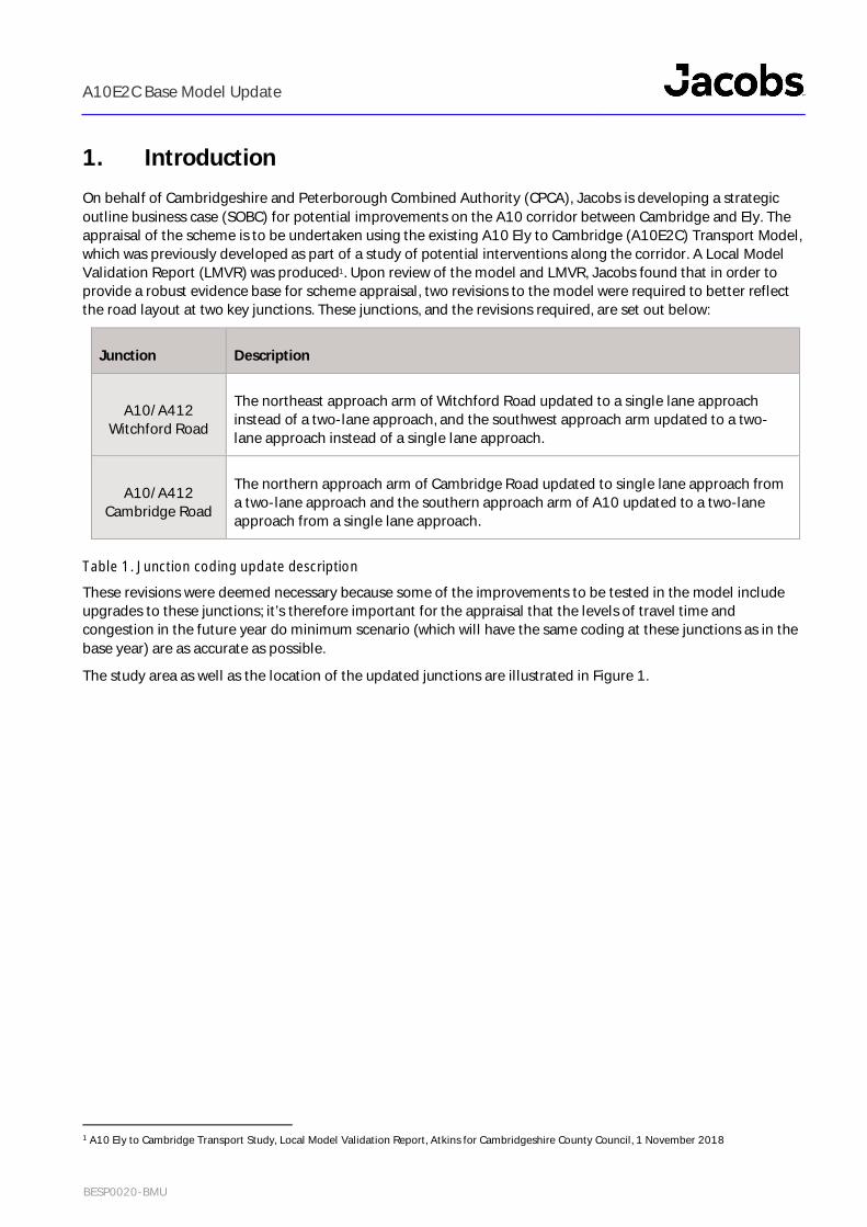
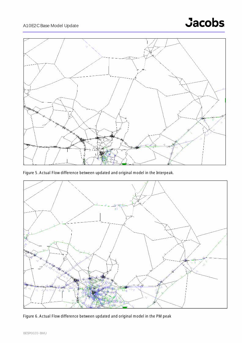
to Figure 6. These show the actual flow difference in Passenger Car Units (PCUs) for the AM peak, Interpeak andPM peak models. The green bandwidths show an increase in flow in the updated model and the blue show adecrease.

A10E2C Base Model Update
BESP0020-BMU
Figure 4: Actual Flow difference between updated and original model in the AM peak
A10E2C Base Model Update
BESP0020-BMU
Figure 5. Actual Flow difference between updated and original model in the Interpeak.
Figure 6. Actual Flow difference between updated and original model in the PM peak

A10E2C Base Model Update
BESP0020-BMU
In all time periods, there are minimal changes in flow along the A10 and on the revised junctions. This indicatesthat the junction coding updates have no significant impact on the A10 corridor. There are also some relativelysmall changes in flow in the centre of Cambridge: The flow changes range from an increase of 14 PCUs to adecrease of 9 PCUs for the AM peak and from an increase of 4 PCUs to decrease of 9 PCUs in the PM Peak. Giventheir distance from those junctions which were revised, these changes are considered to be due to backgroundnoise in the assignment rather than as a direct result of the changes to the network.
3.1.2 Total Delays
Total delay is calculated based on link delay and turning movement delay. Figure 7 to Figure 9 show thedifference in the total delay in seconds between the updated and original base models, for the AM peak, IP andPM peak for the area. The green bandwidths illustrate an increase in total delay in the updated model and theblue show a decrease.
Figure 7. Total delay difference between updated and original model in the AM peak

A10E2C Base Model Update
BESP0020-BMU
Figure 8. Total delay difference between updated and original model in the interpeak
Figure 9. Total delay difference between updated and original model in the PM peak

A10E2C Base Model Update
BESP0020-BMU
All time periods show minimal change in delay between the two scenarios along A10 corridor. There are someminor changes in delay in Cambridge for the PM and interpeak, but they are very marginal, to the effect thatthere is no real difference.
In the AM peak, there were more notable changes inside Cambridge compared to the other two periods, due tothe differences in flows noted as a result of model noise in the assignment. The greatest change in AM peak is anincrease of around 156 seconds at New Street westbound and this is due to the small flow increase of 14 PCUson the road. Whilst this is a large change, around the core study area of the A10 corridor, there are no changes.

A10E2C Base Model Update
BESP0020-BMU
4. Summary
4.1 Model differences
The comparison of updated and original models shows that for the majority of the modelled area the changes inflows effected by the revisions to the network coding are very small, and only increase to more than one or twoPCUs in flow within Cambridge; in all other areas, and particularly along the A10 corridor, there is barely anychange. Given how far away it is from the revised junctions, the changes that do occur in Cambridge areconsidered to be due to model noise rather than a direct effect of the network changes. Whilst it is noted that inthe AM peak model there are some very large changes in delays in Cambridge, it should also be noted that theseare a significant distance away from the A10 corridor.
4.2 Implications for the A10 SOBC
Given that the changes in link flows as a result of the revisions are so small, the assignment calibration andvalidation as reported in the A10E2C LMVR continues to be representative of the state of the base model, evenwith the revisions to the network coding. For that reason, the revised A10E2C base model can be used as thestarting point for developing forecast scenarios to be used for the appraisal of schemes along the A10 corridor. Itis therefore recommended that the LMVR continue to be used for reporting on the A10E2C model, and that thisnote be a supplementary addendum to that report.