A1 e 0801 17 - Department of Biologybiology4.wustl.edu/imaging-facility/Nikon-A1-Confocal.pdf ·...
11
Confocal Microscope A1 Confocal Microscope
Transcript of A1 e 0801 17 - Department of Biologybiology4.wustl.edu/imaging-facility/Nikon-A1-Confocal.pdf ·...

Confocal Microscope A1
C o n f o c a l M i c r o s c o p e
2 3
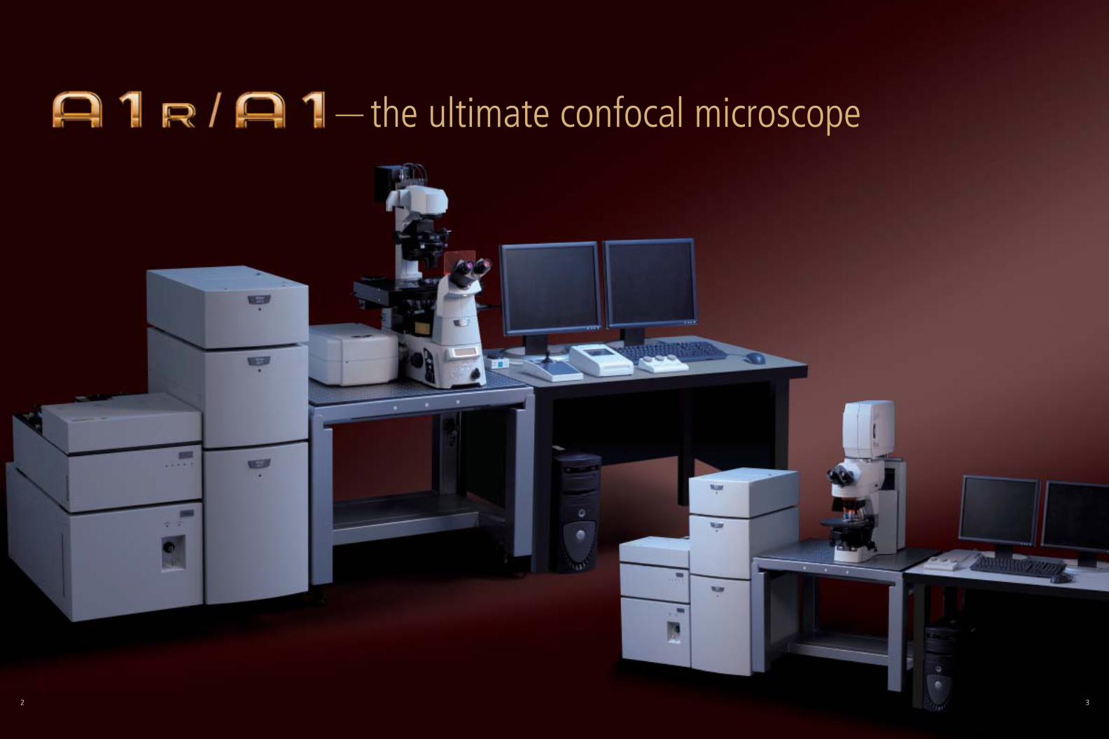
— the ultimate confocal microscope
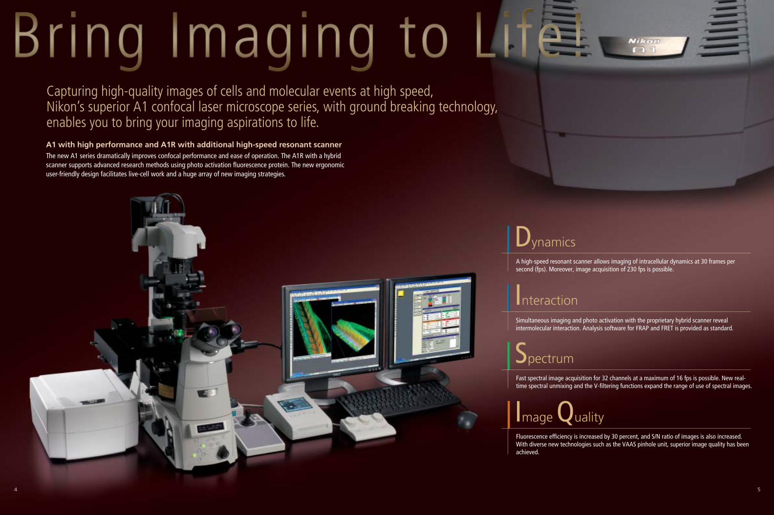
Capturing high-quality images of cells and molecular events at high speed, Nikon’s superior A1 confocal laser microscope series, with ground breaking technology, enables you to bring your imaging aspirations to life.A1 with high performance and A1R with additional high-speed resonant scannerThe new A1 series dramatically improves confocal performance and ease of operation. The A1R with a hybridscanner supports advanced research methods using photo activation fluorescence protein. The new ergonomicuser-friendly design facilitates live-cell work and a huge array of new imaging strategies.
DynamicsA high-speed resonant scanner allows imaging of intracellular dynamics at 30 frames persecond (fps). Moreover, image acquisition of 230 fps is possible.
InteractionSimultaneous imaging and photo activation with the proprietary hybrid scanner revealintermolecular interaction. Analysis software for FRAP and FRET is provided as standard.
SpectrumFast spectral image acquisition for 32 channels at a maximum of 16 fps is possible. New real-time spectral unmixing and the V-filtering functions expand the range of use of spectral images.
Image QualityFluorescence efficiency is increased by 30 percent, and S/N ratio of images is also increased. With diverse new technologies such as the VAAS pinhole unit, superior image quality has beenachieved.
4 5
Imaging
Photo activation
Resonant scanner
Non-resonant scanner
Photo activation laser
High-speed imaging laser
Hyper selector
Hyper selector
Simultaneous photo activation and imaging
Simultaneous photo activation and fluorescence imaging is conducted using non-resonant and resonant scanners.Because the resonant scanner can capture images at 30 fps, image acquisition of high-speed biological processesafter photo activation is possible.
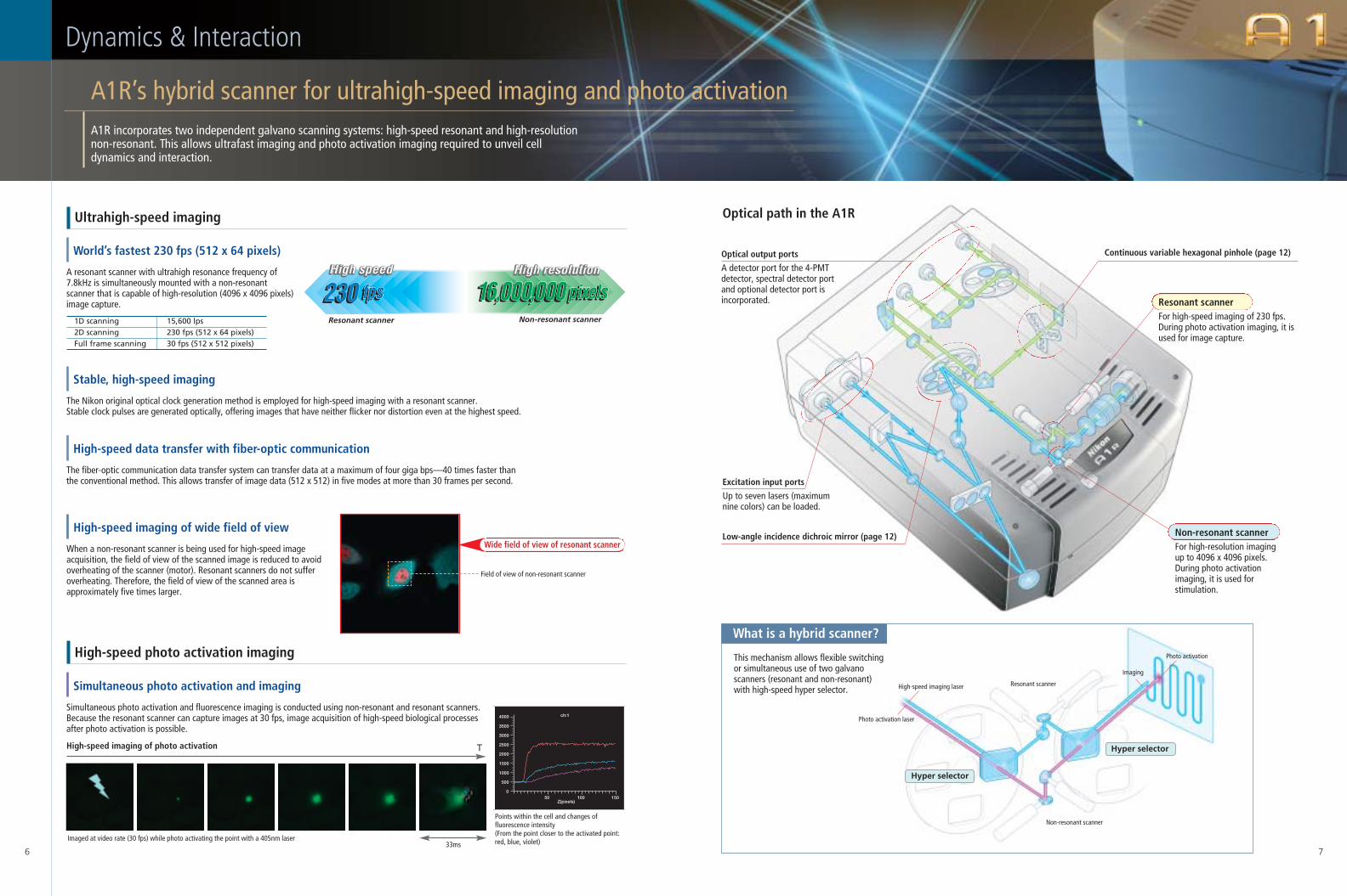
World’s fastest 230 fps (512 x 64 pixels)
A resonant scanner with ultrahigh resonance frequency of7.8kHz is simultaneously mounted with a non-resonantscanner that is capable of high-resolution (4096 x 4096 pixels)image capture.
Stable, high-speed imaging
The Nikon original optical clock generation method is employed for high-speed imaging with a resonant scanner. Stable clock pulses are generated optically, offering images that have neither flicker nor distortion even at the highest speed.
High-speed imaging of photo activation
Field of view of non-resonant scanner
What is a hybrid scanner?
6 7
Optical output ports
A detector port for the 4-PMTdetector, spectral detector portand optional detector port isincorporated.
Continuous variable hexagonal pinhole (page 12)
Low-angle incidence dichroic mirror (page 12)
Excitation input ports
Up to seven lasers (maximumnine colors) can be loaded.
Imaged at video rate (30 fps) while photo activating the point with a 405nm laser
Points within the cell and changes offluorescence intensity(From the point closer to the activated point:red, blue, violet)33ms
T
High-speed data transfer with fiber-optic communication
The fiber-optic communication data transfer system can transfer data at a maximum of four giga bps—40 times faster thanthe conventional method. This allows transfer of image data (512 x 512) in five modes at more than 30 frames per second.
High-speed imaging of wide field of view
When a non-resonant scanner is being used for high-speed imageacquisition, the field of view of the scanned image is reduced to avoidoverheating of the scanner (motor). Resonant scanners do not sufferoverheating. Therefore, the field of view of the scanned area isapproximately five times larger.
Ultrahigh-speed imaging
A1R’s hybrid scanner for ultrahigh-speed imaging and photo activation
Dynamics & Interaction
A1R incorporates two independent galvano scanning systems: high-speed resonant and high-resolutionnon-resonant. This allows ultrafast imaging and photo activation imaging required to unveil celldynamics and interaction.
High-speed photo activation imaging
Resonant scannerFor high-speed imaging of 230 fps.During photo activation imaging, it isused for image capture.
Non-resonant scannerFor high-resolution imagingup to 4096 x 4096 pixels.During photo activationimaging, it is used forstimulation.
1D scanning 15,600 lps2D scanning 230 fps (512 x 64 pixels)Full frame scanning 30 fps (512 x 512 pixels)
Optical path in the A1R
This mechanism allows flexible switchingor simultaneous use of two galvanoscanners (resonant and non-resonant)with high-speed hyper selector.
Resonant scanner Non-resonant scanner
4000
3500
3000
2500
2000
1500
1000
500
50 100 1500
Z(pixels)
ch:1
Wide field of view of resonant scanner
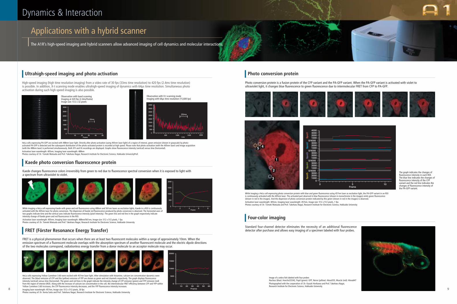
High-speed imaging (high time resolution imaging) from a video rate of 30 fps (33ms time resolution) to 420 fps (2.4ms time resolution)is possible. In addition, X-t scanning mode enables ultrahigh-speed imaging of dynamics with 64µs time resolution. Simultaneous photoactivation during such high-speed imaging is also possible.
Photo conversion protein is a fusion protein of the CFP variant and the PA-GFP variant. When the PA-GFP variant is activated with violet toultraviolet light, it changes blue fluorescence to green fluorescence due to intermolecular FRET from CFP to PA-GFP.
Standard four-channel detector eliminates the necessity of an additional fluorescencedetector after purchase and allows easy imaging of a specimen labeled with four probes.
8 9
Ultrahigh-speed imaging and photo activation
Applications with a hybrid scanner
Dynamics & Interaction
The A1R’s high-speed imaging and hybrid scanners allow advanced imaging of cell dynamics and molecular interactions.
Photo conversion protein
FRET is a physical phenomenon that occurs when there are at least two fluorescent molecules within a range of approximately 10nm. When theemission spectrum of a fluorescent molecule overlaps with the absorption spectrum of another fluorescent molecule and the electric dipole directionsof the two molecules correspond, radiationless energy transfer from a donor molecule to an acceptor molecule may occur.
FRET (Förster Resonance Energy Transfer)
Kaede changes fluorescence colors irreversibly from green to red due to fluorescence spectral conversion when it is exposed to light witha spectrum from ultraviolet to violet.
Kaede photo conversion fluorescence protein
Four-color imaging
HeLa cells expressing PA-GFP are excited with 488nm laser light. Directly after photo-activation (using 405nm laser light) of a region of interest, green emission (shown in grayscale) by photo-activated PA-GFP is detected and the subsequent distribution of the photo-activated protein is recorded at high speed. Please note that photo-activation (with the 405nm laser) and image acquisition(with the 488nm laser) is performed simultaneously. Both XYt and Xt recordings are displayed. Graphs show fluorescence intensity (vertical) versus time (horizontal).Activation laser wavelength: 405nm, Imaging laser wavelength: 488nmPhotos courtesy of: Dr. Tomoki Matsuda and Prof. Takeharu Nagai, Research Institute for Electronic Science, Hokkaido UniversityProf.
Observation with band scanningImaging at 420 fps (2.4ms/frame)Image size: 512 x 32 pixels
Observation with X-t scanning modeImaging with 64µs time resolution (15,600 lps)
3000
2500
2000
1500
1000
500
010 20 30 40 50
Frame
4000
3500
3000
2500
2000
1500
500
500 1000 1500 20000
1000
Line
20ms
20ms
While imaging a HeLa cell expressing Kaede with green and red fluorescence using 488nm and 561nm lasers as excitation lights, Kaede in a ROI is continuouslyactivated with the 405nm laser for photo conversion. The dispersion of Kaede red fluorescence produced by photo conversion is observed. The horizontal axes oftwo graphs indicate time and the vertical axes indicate fluorescence intensity (pixel intensity). The green line and red line in the graph respectively indicateintensity change of Kaede green and red fluorescence in the ROI. Activation laser wavelength: 405nm, Imaging laser wavelength: 488nm/561nm, Image size: 512 x 512 pixels, 1 fpsPhotos courtesy of: Dr. Tomoki Matsuda and Prof. Takeharu Nagai, Research Institute for Electronic Science, Hokkaido University
2000
1500
1000
500
02 4 6 8
Frame
HeLa cells expressing Yellow Cameleon 3.60 were excited with 457nm laser light. After stimulation with histamine, calcium ion concentration dynamics wereobserved. The (blue) emission of CFP and the (yellow) emission of YFP are shown as green and red channels respectively. The graph displays fluorescenceintensity (vertical) versus time (horizontal). The green and red lines in the graph indicate the intensity change of CFP emission (green) and YFP emission (red)from the region of interest (ROI). Along with the increase of calcium ion concentration in the cell, the intermolecular FRET efficiency between CFP and YFP withinYellow Cameleon 3.60 increases, the CFP fluorescence intensity decreases, and the YFP fluorescence intensity increases.Imaging laser wavelength: 457nm, Image size: 512 x 512 pixels, 30 fpsPhotos courtesy of: Dr. Kenta Saito and Prof. Takeharu Nagai, Research Institute for Electronic Science, Hokkaido University
2000
1500
1000
500
010 20
Frame
30 40 50 60
While imaging a HeLa cell expressing photo conversion protein with blue and green fluorescence using 457nm laser as excitation light, the PA-GFP variant in an ROIis continuously activated with the 405nm laser. The activated part observed in blue fluorescence (shown in monochrome in the images) emits green fluorescence(shown in red in the images). And the dispersion of photo conversion protein indicated by this green (shown in red in the images) is observed.Activation laser wavelength: 405nm, Imaging laser wavelength: 457nm, Image size: 512 x 512 pixels, 1 fpsPhotos courtesy of: Dr. Tomoki Matsuda and Prof. Takeharu Nagai, Research Institute for Electronic Science, Hokkaido University
The graph indicates the changes offluorescence intensity in each ROI.The blue line indicates the changes offluorescence intensity of the CFPvariant and the red line indicates thechanges of fluorescence intensity ofthe PA-GFP variant.
4000
0 5 10
0/4000
300020001000
0/4000
300020001000
0/4000
300020001000
0/4000
300020001000
0
300020001000
Frame
Spot2
Spot3
Spot4
Spot5
Spot1
Image of a zebra fish labeled with four probesNucleus (blue): Hoechst33342, Pupil (green): GFP, Nerve (yellow): Alexa555, Muscle (red): Alexa647Photographed with the cooperation of: Dr. Kazuki Horikawa and Prof. Takeharu Nagai, Research Institute for Electronic Science, Hokkaido University
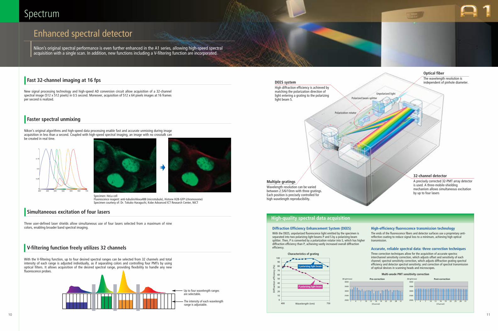
32-channel detectorA precisely corrected 32-PMT array detectoris used. A three-mobile-shieldingmechanism allows simultaneous excitationby up to four lasers
DEES systemHigh diffraction efficiency is achieved bymatching the polarization direction oflight entering a grating to the polarizinglight beam S.
Unpolarized light
Polarized beam splitter
Optical fiberThe wavelength resolution isindependent of pinhole diameter.
S1
P S1
S2
S2
Polarization rotator
Multiple gratingsWavelength resolution can be variedbetween 2.5/6/10nm with three gratings.Each position is precisely controlled forhigh wavelength reproducibility.
New signal processing technology and high-speed AD conversion circuit allow acquisition of a 32-channelspectral image (512 x 512 pixels) in 0.5 second. Moreover, acquisition of 512 x 64 pixels images at 16 framesper second is realized.
10 11
1
0
0.75
0.5
0.25
400 450 500 550 600 650 700
Nikon’s original algorithms and high-speed data processing enable fast and accurate unmixing during imageacquisition in less than a second. Coupled with high-speed spectral imaging, an image with no crosstalk canbe created in real time.
Up to four wavelength rangesare selectable.
The intensity of each wavelengthrange is adjustable.
Three user-defined laser shields allow simultaneous use of four lasers selected from a maximum of ninecolors, enabling broader band spectral imaging.
With the V-filtering function, up to four desired spectral ranges can be selected from 32 channels and totalintensity of each range is adjusted individually, as if separating colors and controlling four PMTs by usingoptical filters. It allows acquisition of the desired spectral range, providing flexibility to handle any newfluorescence probes.
High-quality spectral data acquisition
(Brightness)
(Channel)
2000
2500
3000
3500
4000
1 4 7 10 13 16 19 22 25 28 31
Pre-correction (Brightness)
(Channel)
2000
2500
3000
3500
4000
1 4 7 10 13 16 19 22 25 28 31
Post-correction
Multi-anode PMT sensitivity correction
Accurate, reliable spectral data: three correction techniquesThree correction techniques allow for the acquisition of accurate spectra:interchannel sensitivity correction, which adjusts offset and sensitivity of eachchannel; spectral sensitivity correction, which adjusts diffraction grating spectralefficiency and detector spectral sensitivity; and correction of spectral transmissionof optical devices in scanning heads and microscopes.
Diffraction Efficiency Enhancement System (DEES)With the DEES, unpolarized fluorescence light emitted by the specimen isseparated into two polarizing light beams P and S by a polarizing beamsplitter. Then, P is converted by a polarization rotator into S, which has higherdiffraction efficiency than P, achieving vastly increased overall diffractionefficiency.
0
400 750
10
20
30
40
50
60
70
80
90
100
Wavelength (nm)
Dif
frac
tio
n e
ffic
ien
cy (
%) S polarizing light beam
P polarizing light beam
Characteristics of grating
High-efficiency fluorescence transmission technologyThe ends of the fluorescence fibers and detector surfaces use a proprietary anti-reflective coating to reduce signal loss to a minimum, achieving high opticaltransmission.
Enhanced spectral detector
Spectrum
Nikon’s original spectral performance is even further enhanced in the A1 series, allowing high-speed spectralacquisition with a single scan. In addition, new functions including a V-filtering function are incorporated.
Fast 32-channel imaging at 16 fps
Faster spectral unmixing
Simultaneous excitation of four lasers
V-filtering function freely utilizes 32 channels
Specimen: HeLa cellFluorescence reagent: anti-tubulin/Alexa488 (microtubule), Histone H2B-GFP (chromosome)Specimen courtesy of: Dr. Tokuko Haraguchi, Kobe Advanced ICT Research Center, NICT
Square pinhole Hexagonal pinhole
With the A1series, the industry’s first low-angle incidence method is employed on dichroic mirrors.High transmission rate of an average 98% and a 30% increase of fluorescence efficiency are realized.
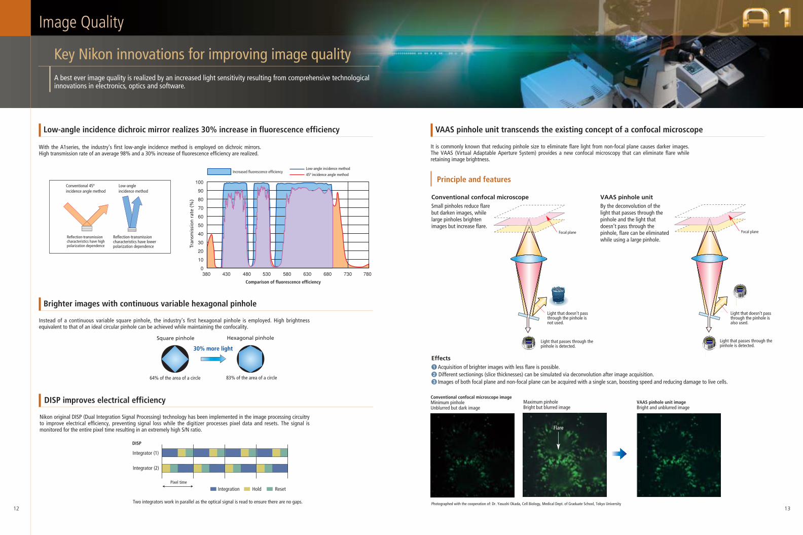
It is commonly known that reducing pinhole size to eliminate flare light from non-focal plane causes darker images.The VAAS (Virtual Adaptable Aperture System) provides a new confocal microscopy that can eliminate flare whileretaining image brightness.
Instead of a continuous variable square pinhole, the industry’s first hexagonal pinhole is employed. High brightnessequivalent to that of an ideal circular pinhole can be achieved while maintaining the confocality.
Nikon original DISP (Dual Integration Signal Processing) technology has been implemented in the image processing circuitryto improve electrical efficiency, preventing signal loss while the digitizer processes pixel data and resets. The signal ismonitored for the entire pixel time resulting in an extremely high S/N ratio.
Principle and features
Effects1Acquisition of brighter images with less flare is possible.2 Different sectionings (slice thicknesses) can be simulated via deconvolution after image acquisition.3 Images of both focal plane and non-focal plane can be acquired with a single scan, boosting speed and reducing damage to live cells.
100
90
80
70
60
50
40
30
20
10
0380 430 480 530 580 630 680 730 780
Tran
smis
sio
n r
ate
(%)
Conventional 45ºincidence angle method
Low-angleincidence method
Reflection-transmissioncharacteristics have highpolarization dependence
Comparison of fluorescence efficiency
Reflection-transmissioncharacteristics have lowerpolarization dependence
Increased fluorescence efficiency Low-angle incidence method
45º incidence angle method
64% of the area of a circle 83% of the area of a circle
12 13
Conventional confocal microscope imageMinimum pinhole Unblurred but dark image
Maximum pinhole Bright but blurred image
VAAS pinhole unit image Bright and unblurred image
Light that passes through thepinhole is detected.
Light that doesn’t passthrough the pinhole isnot used.
Light that passes through thepinhole is detected.
Light that doesn’t passthrough the pinhole isalso used.
Key Nikon innovations for improving image quality
Image Quality
A best ever image quality is realized by an increased light sensitivity resulting from comprehensive technologicalinnovations in electronics, optics and software.
Low-angle incidence dichroic mirror realizes 30% increase in fluorescence efficiency VAAS pinhole unit transcends the existing concept of a confocal microscope
Brighter images with continuous variable hexagonal pinhole
DISP improves electrical efficiency
Photographed with the cooperation of: Dr. Yasushi Okada, Cell Biology, Medical Dept. of Graduate School, Tokyo University
30% more light
Conventional confocal microscopeSmall pinholes reduce flarebut darken images, whilelarge pinholes brightenimages but increase flare.
VAAS pinhole unitBy the deconvolution of thelight that passes through thepinhole and the light thatdoesn’t pass through thepinhole, flare can be eliminatedwhile using a large pinhole.
Focal plane Focal plane
Flare
Integrator (1)
Integration Hold ResetPixel time
Integrator (2)
DISP
Two integrators work in parallel as the optical signal is read to ensure there are no gaps.
14 15
The remote controller allows the regulation of major settings of laser,detector, and scanner with simple operation using push buttons anddials.
High-speed image acquisition in the Z direction as well as the XYdirection is possible. By using the piezo motorized Z stage, arbitraryvertical cross-sectional view can be achieved in real time withoutacquiring a 3D image.
In combination with four lasers, simultaneous observation of fourfluorescence labels is possible as standard. Each of three filter wheelscan mount six filter cubes that are commonly used for a microscope, andare all easily changeable by users. This combines modularity, flexibilitywith user friendliness.
NIS-Elements C
Simple image acquisition
・ Basic operationParameters for basic image acquisition are integrated in a singlewindow, allowing simple image acquisition.
・ Optical settingBy simply selecting a fluorescence probe, an appropriate filter and laserwavelength are set automatically. Microscope setup is also conductedautomatically.
Diverse application
・ Parameter setting for photo activationTiming and imaging parameters forphoto activation are set intuitively.
・ Multidimensional image acquisitionAcquisition of images with a freecombination of multidimensionalparameters including X, Y, Z, t and λ ispossible.
Reliable analysis functions
Real-time ratio display
Deconvolution
High-speed 3D rendering
Multidimensional image display (nD Viewer)
Synchronized display of multidimensional images (Viewsynchronizer)
Diverse measurement and statistical processing
Powerful image database function
Colocalization and FRET
4-channel detector unit with changeable filters
Increased flexibility and ease of use
Easy to Use
Control software NIS-Elements C features easy operation and diverse analysis functions. Combined with aremote controller and other hardware, it provides a comprehensive operational environment.
Spline Z scans for real-time display of cross-sectional images
Easy operation by remote controller
Superior operability based on analysis of every possible confocal microscope operation pattern realizes easy operation withoutan instruction manual, satisfying both beginners and experienced confocal users. Taking advantage of the hybrid scanner, itenables a complicated sequence of experiments such as photo activation to be carried out with simple setting and operation.
CLEM (Controlled Light-Exposure Microscopy)
During lengthy time-lapse imaging, cellular apoptosis caused by the exposure to light is a problem. The CLEM sensesthe fluorescence signals and controls the on/off of the laser exposure depending on signal intensity. This reduces laserexposure and alleviates the problem of cellular apoptosis.
0 min
10 µm
27 min 96 min 169 min
0 min 27 min 96 min 169 min
Expression GFP in Histone 2B of HeLa cellExcitation laser wavelength: 488nm, Fluorescence acquisitionwavelength: 500-530nm, Single image acquisition time: 4seconds, Intervals: 1 minute, Total acquisition time: 3 hoursPhotos courtesy of: Dr. Merel Adjobo-Hermans, Department of Cell Biology, Amsterdam University, The Netherlands
Non-CLEM: Apoptosis occurs after a lapse of one hour
CLEM: Apoptosis doesn’t occur even after a lapse of 2.5 hours
16 17
L1L2L3L4
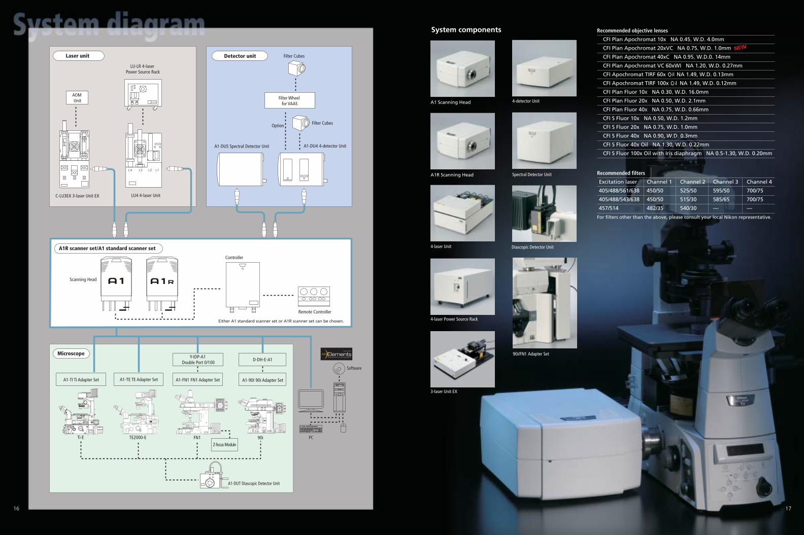
Either A1 standard scanner set or A1R scanner set can be chosen.
PC
Software
A1-DUT Diascopic Detector Unit
Filter Wheel for VAAS
AOM Unit
Laser unit
A1R scanner set/A1 standard scanner set
Microscope
Detector unit Filter Cubes
Filter CubesOption
A1-DUS Spectral Detector Unit
C-LU3EX 3-laser Unit EX
A1-DU4 4-detector Unit
LU-LR 4-laser Power Source Rack
Scanning Head
TE2000-E FN1 90i
Controller
Remote Controller
LU4 4-laser Unit
A1-TE TE Adapter SetA1-TI Ti Adapter Set
Z-focus Module
Y-IDP-A1 Double Port 0/100
D-DH-E-A1
A1-FN1 FN1 Adapter Set A1-90I 90i Adapter Set
Ti-E
Recommended filters
Excitation laser Channel 1 Channel 2 Channel 3 Channel 4
405/488/561/638 450/50 525/50 595/50 700/75
405/488/543/638 450/50 515/30 585/65 700/75
457/514 482/35 540/30 — —
For filters other than the above, please consult your local Nikon representative.
Recommended objective lenses
CFI Plan Apochromat 10x NA 0.45, W.D. 4.0mm
CFI Plan Apochromat 20xVC NA 0.75, W.D. 1.0mm
CFI Plan Apochromat 40xC NA 0.95, W.D.0. 14mm
CFI Plan Apochromat VC 60xWI NA 1.20, W.D. 0.27mm
CFI Apochromat TIRF 60x NA 1.49, W.D. 0.13mm
CFI Apochromat TIRF 100x NA 1.49, W.D. 0.12mm
CFI Plan Fluor 10x NA 0.30, W.D. 16.0mm
CFI Plan Fluor 20x NA 0.50, W.D. 2.1mm
CFI Plan Fluor 40x NA 0.75, W.D. 0.66mm
CFI S Fluor 10x NA 0.50, W.D. 1.2mm
CFI S Fluor 20x NA 0.75, W.D. 1.0mm
CFI S Fluor 40x NA 0.90, W.D. 0.3mm
CFI S Fluor 40x Oil NA 1.30, W.D. 0.22mm
CFI S Fluor 100x Oil with Iris diaphragm NA 0.5-1.30, W.D. 0.20mm
NEW
A1 Scanning Head
A1R Scanning Head
90i/FN1 Adapter Set
4-laser Unit
3-laser Unit EX
4-laser Power Source Rack
Spectral Detector Unit
4-detector Unit
Diascopic Detector Unit
System components
Specifications
Standard image acquisitionScanner: non-resonant scanner x2Pixel size: max. 4096 x 4096 pixelsScanning speed: 4 fps (512 x 512 pixels) Zoom: 1-1000x continuously variableScanning mode: X-Y, XY rotation, Free line, Line Z
18 19
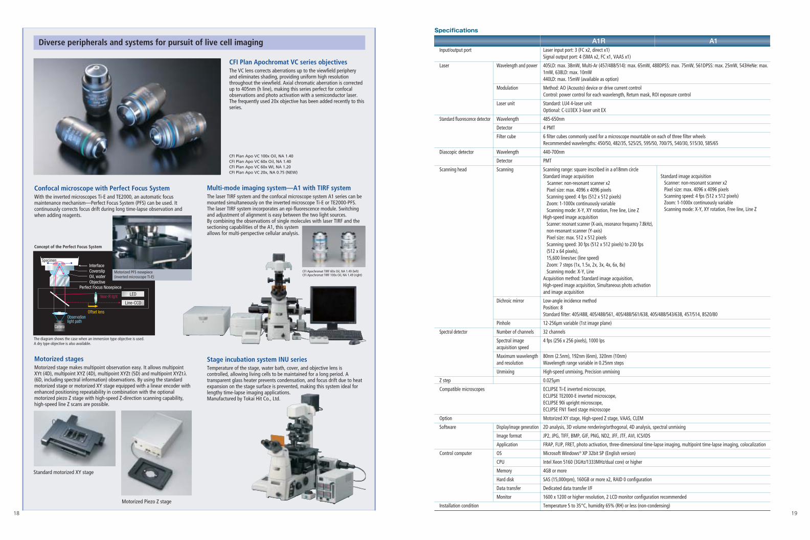
Confocal microscope with Perfect Focus SystemWith the inverted microscopes Ti-E and TE2000, an automatic focusmaintenance mechanism—Perfect Focus System (PFS) can be used. Itcontinuously corrects focus drift during long time-lapse observation andwhen adding reagents.
Stage incubation system INU seriesTemperature of the stage, water bath, cover, and objective lens iscontrolled, allowing living cells to be maintained for a long period. Atransparent glass heater prevents condensation, and focus drift due to heatexpansion on the stage surface is prevented, making this system ideal forlengthy time-lapse imaging applications.Manufactured by Tokai Hit Co., Ltd.
Motorized stagesMotorized stage makes multipoint observation easy. It allows multipointXYt (4D), multipoint XYZ (4D), multipoint XYZt (5D) and multipoint XYZtλ(6D, including spectral information) observations. By using the standardmotorized stage or motorized XY stage equipped with a linear encoder withenhanced positioning repeatability in combination with the optionalmotorized piezo Z stage with high-speed Z-direction scanning capability,high-speed line Z scans are possible.
Concept of the Perfect Focus System
Diverse peripherals and systems for pursuit of live cell imaging
CFI Plan Apochromat VC series objectivesThe VC lens corrects aberrations up to the viewfield peripheryand eliminates shading, providing uniform high resolutionthroughout the viewfield. Axial chromatic aberration is correctedup to 405nm (h line), making this series perfect for confocalobservations and photo activation with a semiconductor laser.The frequently used 20x objective has been added recently to thisseries.
Multi-mode imaging system—A1 with TIRF systemThe laser TIRF system and the confocal microscope system A1 series can bemounted simultaneously on the inverted microscope Ti-E or TE2000-PFS.The laser TIRF system incorporates an epi-fluorescence module. Switchingand adjustment of alignment is easy between the two light sources.By combining the observations of single molecules with laser TIRF and thesectioning capabilities of the A1, this system allows for multi-perspective cellular analysis.
Standard motorized XY stage
Motorized Piezo Z stage
CFI Apochromat TIRF 60x Oil, NA 1.49 (left)CFI Apochromat TIRF 100x Oil, NA 1.49 (right)
CFI Plan Apo VC 100x Oil, NA 1.40 CFI Plan Apo VC 60x Oil, NA 1.40 CFI Plan Apo VC 60x WI, NA 1.20 CFI Plan Apo VC 20x, NA 0.75 (NEW)
CoverslipInterface
Perfect Focus Nosepiece
Specimen
LED
Line-CCD
Camera
Observation light path
Offset lens
Oil, waterObjective
Near-IR light
The diagram shows the case when an immersion type objective is used. A dry type objective is also available.
Motorized PFS nosepiece(inverted microscope Ti-E)
A1R A1Input/output port Laser input port: 3 (FC x2, direct x1)
Signal output port: 4 (SMA x2, FC x1, VAAS x1)
Laser Wavelength and power 405LD: max. 38mW, Multi-Ar (457/488/514): max. 65mW, 488DPSS: max. 75mW, 561DPSS: max. 25mW, 543HeNe: max. 1mW, 638LD: max. 10mW440LD: max. 15mW (available as option)
Modulation Method: AO (Acousto) device or drive current controlControl: power control for each wavelength, Return mask, ROI exposure control
Laser unit Standard: LU4 4-laser unitOptional: C-LU3EX 3-laser unit EX
Standard fluorescence detector Wavelength 485-650nm
Detector 4 PMT
Filter cube 6 filter cubes commonly used for a microscope mountable on each of three filter wheelsRecommended wavelengths: 450/50, 482/35, 525/25, 595/50, 700/75, 540/30, 515/30, 585/65
Diascopic detector Wavelength 440-700nm
Detector PMT
Scanning head Scanning Scanning range: square inscribed in a ø18mm circleStandard image acquisition
Scanner: non-resonant scanner x2Pixel size: max. 4096 x 4096 pixelsScanning speed: 4 fps (512 x 512 pixels) Zoom: 1-1000x continuously variableScanning mode: X-Y, XY rotation, Free line, Line Z
High-speed image acquisitionScanner: resonant scanner (X-axis, resonance frequency 7.8kHz),non-resonant scanner (Y-axis)Pixel size: max. 512 x 512 pixelsScanning speed: 30 fps (512 x 512 pixels) to 230 fps (512 x 64 pixels), 15,600 lines/sec (line speed)Zoom: 7 steps (1x, 1.5x, 2x, 3x, 4x, 6x, 8x)Scanning mode: X-Y, Line
Acquisition method: Standard image acquisition,High-speed image acquisition, Simultaneous photo activation and image acquisition
Dichroic mirror Low-angle incidence methodPosition: 8Standard filter: 405/488, 405/488/561, 405/488/561/638, 405/488/543/638, 457/514, BS20/80
Pinhole 12-256µm variable (1st image plane)
Spectral detector Number of channels 32 channels
Spectral image 4 fps (256 x 256 pixels), 1000 lpsacquisition speed
Maximum wavelength 80nm (2.5nm), 192nm (6nm), 320nm (10nm)and resolution Wavelength range variable in 0.25nm steps
Unmixing High-speed unmixing, Precision unmixing
Z step 0.025µm
Compatible microscopes ECLIPSE Ti-E inverted microscope,ECLIPSE TE2000-E inverted microscope, ECLIPSE 90i upright microscope, ECLIPSE FN1 fixed stage microscope
Option Motorized XY stage, High-speed Z stage, VAAS, CLEM
Software Display/image generation 2D analysis, 3D volume rendering/orthogonal, 4D analysis, spectral unmixing
Image format JP2, JPG, TIFF, BMP, GIF, PNG, ND2, JFF, JTF, AVI, ICS/IDS
Application FRAP, FLIP, FRET, photo activation, three-dimensional time-lapse imaging, multipoint time-lapse imaging, colocalization
Control computer OS Microsoft Windows® XP 32bit SP (English version)
CPU Intel Xeon 5160 (3GHz/1333MHz/dual core) or higher
Memory 4GB or more
Hard disk SAS (15,000rpm), 160GB or more x2, RAID 0 configuration
Data transfer Dedicated data transfer I/F
Monitor 1600 x 1200 or higher resolution, 2 LCD monitor configuration recommended
Installation condition Temperature 5 to 35°C, humidity 65% (RH) or less (non-condensing)
EMISSION POWER
○
I
1150
2990
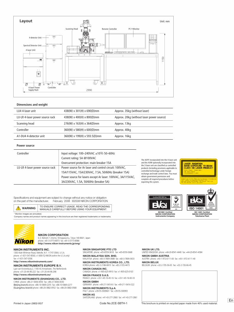
Layout Unit: mm
Dimensions and weight
LU4 4-laser unit 438(W) x 301(H) x 690(D)mm Approx. 35kg (without laser)
LU-LR 4-laser power source rack 438(W) x 400(H) x 800(D)mm Approx. 20kg (without laser power source)
Scanning head 276(W) x 163(H) x 364(D)mm Approx. 13kg
Controller 360(W) x 580(H) x 600(D)mm Approx. 40kg
A1-DU4 4-detector unit 360(W) x 199(H) x 593.5(D)mm Approx. 16kg
Power source
Controller Input voltage: 100–240VAC ±10% 50–60Hz
Current rating: 5A @100VAC
Overcurrent protection: main breaker 15A
LU-LR 4-laser power source rack Power source for Ar laser and control circuit: 100VAC,
15A/115VAC, 15A/230VAC, 7.5A, 50/60Hz (breaker 15A)
Power source for lasers except Ar laser: 100VAC, 3A/115VAC,
3A/230VAC, 1.5A, 50/60Hz (breaker 5A)
EnThis brochure is printed on recycled paper made from 40% used material.Printed in Japan (0802-00)T Code No.2CE-SBTH-1
Specifications and equipment are subject to change without any notice or obligationon the part of the manufacturer. February 2008 ©2008 NIKON CORPORATION
* Monitor images are simulated.Company names and product names appearing in this brochure are their registered trademarks or trademarks.
WARNINGTO ENSURE CORRECT USAGE, READ THE CORRESPONDINGMANUALS CAREFULLY BEFORE USING YOUR EQUIPMENT.
NIKON CORPORATION6-3, Nishiohi 1-chome, Shinagawa-ku, Tokyo 140-8601, Japanphone: +81-3-3773-8973 fax: +81-3-3773-8986 http://www.nikon-instruments.jp/eng/
NIKON INSTRUMENTS INC.1300 Walt Whitman Road, Melville, N.Y. 11747-3064, U.S.A.phone: +1-631-547-8500; +1-800-52-NIKON (within the U.S.A.only) fax: +1-631-547-0306http://www.nikoninstruments.com/
NIKON INSTRUMENTS EUROPE B.V.Laan van Kronenburg 2, 1183 AS Amstelveen, The Netherlandsphone: +31-20-44-96-222 fax: +31-20-44-96-298http://www.nikoninstruments.eu/
NIKON INSTRUMENTS (SHANGHAI) CO., LTD.CHINA phone: +86-21-5836-0050 fax: +86-21-5836-0030(Beijing branch) phone: +86-10-5869-2255 fax: +86-10-5869-2277(Guangzhou branch) phone: +86-20-3882-0552 fax: +86-20-3882-0580
NIKON SINGAPORE PTE LTDSINGAPORE phone: +65-6559-3618 fax: +65-6559-3668
NIKON MALAYSIA SDN. BHD.MALAYSIA phone: +60-3-7809-3688 fax: +60-3-7809-3633
NIKON INSTRUMENTS KOREA CO., LTD.KOREA phone: +82-2-2186-8410 fax: +82-2-555-4415
NIKON CANADA INC.CANADA phone: +1-905-625-9910 fax: +1-905-625-0103
NIKON FRANCE S.A.S.FRANCE phone: +33-1-45-16-45-16 fax: +33-1-45-16-00-33
NIKON GMBHGERMANY phone: +49-211-9414-0 fax: +49-211-9414-322
NIKON INSTRUMENTS S.p.A.ITALY phone: +39-55-3009601 fax: +39-55-300993
NIKON AGSWITZERLAND phone: +41-43-277-2860 fax: +41-43-277-2861
NIKON UK LTD. UNITED KINGDOM phone: +44-20-8541-4440 fax: +44-20-8541-4584
NIKON GMBH AUSTRIA AUSTRIA phone: +43-1-972-6111-00 fax: +43-1-972-6111-40
NIKON BELUXBELGIUM phone: +32-2-705-56-65 fax: +32-2-726-66-45
The AOTF incorporated into the 4-laser unitand the AOM optionally incorporated intothe 3-laser unit are classified as controlledproducts (including provisions applicable tocontrolled technology) under foreignexchange and trade control laws. You mustobtain government permission andcomplete all required procedures beforeexporting this system.
4-laser Unit
4-laser Power Supply Rack
Spectral Detector Unit
4-detector Unit
Scanning Head
Controller
PC+MonitorRemote Controller


![misswelton.weebly.com€¦ · Web view3.3. 1a. [4 marks] Markscheme (A1)(A1) (ft) (A1)(A1) (ft) (C4) Note: Award (A1) for each correct column followed through from the respective](https://static.fdocuments.us/doc/165x107/5f5ea56b239d0f69cb1fd8a1/web-view-33-1a-4-marks-markscheme-a1a1-ft-a1a1-ft-c4-note-award.jpg)