HAND GESTURE AND ACTIVITY RECOGNITION IN ASSISTED LIVING THROUGH WEARABLE
IEEE TRANSACTIONS ON INDUSTRIAL INFORMATICS, VOL. 11, NO. 2, APRIL 2015 485
A Wearable Gesture Recognition Devicefor Detecting Muscular Activities Based
on Air-Pressure SensorsPyeong-Gook Jung, Student Member, IEEE, Gukchan Lim, Seonghyok Kim,
and Kyoungchul Kong, Member, IEEE
Abstract—Recognition of human gestures plays an importantrole in a number of human-interactive applications, such as mobilephones, health monitoring systems, and human-assistive robots.Electromyography (EMG) is one of the most common and intuitivemethods used for detecting gestures based on muscle activities.The EMG, however, is in general, too sensitive to environmen-tal disturbances, such as electrical noise, electromagnetic signals,humidity, and so on. In this paper, a new method for recognizingthe muscular activities is proposed based on air-pressure sensorsand air-bladders. The muscular activity is detected by measuringthe change of the air pressure in an air-bladder contacting theinterested muscle(s). Since the change of the air pressure can bemore robustly measured compared with the change of electric sig-nals appeared on the skin, the proposed sensing method is usefulfor mobile devices due to its great signal-to-noise ratio (SNR) andfast response time. The principle and applications of the proposedsensing method are introduced in this paper. The performance ofthe proposed method is evaluated in terms of linearity, repeatabil-ity, wear-comfort, etc., and is also verified by comparing it with anEMG signal and a motion sensor.
Index Terms—Electromyography (EMG), gesture recognition,mechanomyography (MMG), mobile phones, wearable device,wearable sensors.
I. INTRODUCTION
A S MOBILE devices are entering into our daily lives moreclosely than ever, various input devices have been devel-
oped for the users to operate such devices in a more natural andcomfortable way. Since Apple Inc. introduced the iPod Touch in2007, almost every mobile device has adopted capacitive sens-ing touch screens as an input device. Also, the Wacom tabletand its electronic pen used to be a very special input deviceonly for graphic designers, but nowadays lots of smart phonesare adopting the electronic pens, as well as touch screens, asan input unit (e.g., the Optimus Vu with a Rubberdium Penof LG Electronics Co. and the Galaxy Note series of SamsungElectronics Co.).
Manuscript received April 10, 2014; revised September 30, 2014; acceptedFebruary 04, 2015. Date of publication February 19, 2015; date of currentversion March 27, 2015. Paper no. TII-14-0764.
P.-G. Jung and K. Kong are with the Department of MechanicalEngineering, Sogang University, Seoul 121-742, South Korea (e-mail:[email protected]; [email protected]).
G. Lim and S. Kim are with LG Electronics Co., Seoul 153-801, South Korea(e-mail: [email protected]; [email protected]).
Color versions of one or more of the figures in this paper are available onlineat http://ieeexplore.ieee.org.
Digital Object Identifier 10.1109/TII.2015.2405413
Meanwhile, the advance of mobile devices has also causedlots of social and clinical problems. There are many reportsthat the smart phones increase the incidence of various acci-dents. For example, Governors Highway Safety Association(GHSA) reported that distractions due to smart phones havecontributed to a quarter of the automobile accidents in theUnited States in 2011 [1]. Moreover, a number of clinical prob-lems, the so-called smartphone syndrome, are becoming oneof the most frequent syndromes recently. In order to solvethese critical problems, there is an increasing need of a wear-able gesture recognition system for minimizing the distractionby mobile devices and for unconsciously operating the mobilesystems.
One way of addressing these issues is to detect the humanintention by monitoring the user’s muscular activities. For thispurpose, electromyography (EMG) is noteworthy. The EMGsensor is commonly used to recognize the human intentionbecause it measures the electric potential to activate the mus-cle by electrodes attached on the skin. Theoretically, the EMGsignals are measured in advance to the muscular activation,which renders a huge advantage of EMG in various applica-tions, in particular, assistive robotics [2]. There are a numberof research teams that investigated on the EMG as an inputdevice. Liu, NASA Ames Research Center, Khezri and Jahed,and Oonishi et al. used the EMG sensors for recognizing theintention of an operator [3]–[6]. Zhang et al. used the EMGsensors for neural–machine interface [7]. Thalmic Labs Co.developed a gesture recognition device, the Myo, which is anarmband bracelet that measures EMG signals to control digi-tal devices [8]. However, the electric potential of muscles is, ingeneral, too sensitive to electric noise, because the magnitudeof the electric potential is in the range of submillivolts, whichis significantly small compared to the electric noise induced bywall-electricity. In addition, it requires an amplifier circuit thatincludes a voltage follower and a differential amplifier, whichmakes the electrodes or peripherals slightly bulky. Furthermore,time delay occurs because of signal processing processes toobtain an envelope curve reducing the noise. This unavoid-able delay quenches the biggest advantage of the EMG signalsand these complex processes increase the price of commercialEMG sensors. Another drawback is that it needs to be directlyattached on the skin. These factors make the application ofEMG challenging to mobile devices.
1551-3203 © 2015 IEEE. Personal use is permitted, but republication/redistribution requires IEEE permission.See http://www.ieee.org/publications_standards/publications/rights/index.html for more information.
486 IEEE TRANSACTIONS ON INDUSTRIAL INFORMATICS, VOL. 11, NO. 2, APRIL 2015
An alternative way to detect the muscular activities ismechanomyography (MMG), which measures mechanic sig-nals during muscular contraction. The muscular activity isobserved by mechanical vibration, which is generated by thetremor of each muscle fiber. The MMGs based on an accelerom-eter [9]–[11] and a microphone [12], [13] are commonly used.Comby et al. proposed an MMG-based monitoring device,which measures the degree of tremor [9]. Zheng et al. rec-ognized hand-motion patterns by the MMG [10]. Alves et al.and Courteville et al. recognized the forearm muscular activ-ity based on the MMG [11], [12]. However, the MMG basedon an accelerometer can be used only when the magnitude ofacceleration is distinguishable compared to the gravity acceler-ation and the motion acceleration. The MMG based on a soundtransducer is reliable only in a silent space.
There are also researchers who measured muscular activitiesby force-sensitive resistors (FSRs). Lukowicz et al. proposedwearable force sensors and evaluated the muscular activity[14]–[16]. Since the muscle contraction involves not only thelongitudinal elongation, but also the expansion of its cross-sectional area, it is possible to detect the muscular activity bymonitoring the swelling of muscles by force sensors. However,although the FSR measurement is robust to noise compared tothe other biosignal measurements, the output voltage of FSRsensors is nonlinear because of the relationship between an out-put voltage and the resistance [14]. In addition, the FSR is athin film, similarly to a strain gauge, and thus an input devicewith FSRs should become rigid, which causes discomfort inwearing.
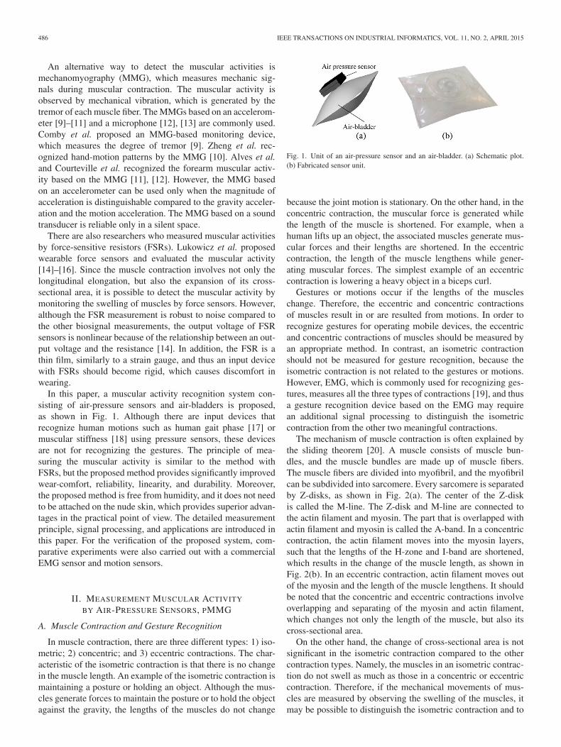
In this paper, a muscular activity recognition system con-sisting of air-pressure sensors and air-bladders is proposed,as shown in Fig. 1. Although there are input devices thatrecognize human motions such as human gait phase [17] ormuscular stiffness [18] using pressure sensors, these devicesare not for recognizing the gestures. The principle of mea-suring the muscular activity is similar to the method withFSRs, but the proposed method provides significantly improvedwear-comfort, reliability, linearity, and durability. Moreover,the proposed method is free from humidity, and it does not needto be attached on the nude skin, which provides superior advan-tages in the practical point of view. The detailed measurementprinciple, signal processing, and applications are introduced inthis paper. For the verification of the proposed system, com-parative experiments were also carried out with a commercialEMG sensor and motion sensors.
II. MEASUREMENT MUSCULAR ACTIVITY
BY AIR-PRESSURE SENSORS, PMMG
A. Muscle Contraction and Gesture Recognition
In muscle contraction, there are three different types: 1) iso-metric; 2) concentric; and 3) eccentric contractions. The char-acteristic of the isometric contraction is that there is no changein the muscle length. An example of the isometric contraction ismaintaining a posture or holding an object. Although the mus-cles generate forces to maintain the posture or to hold the objectagainst the gravity, the lengths of the muscles do not change
Fig. 1. Unit of an air-pressure sensor and an air-bladder. (a) Schematic plot.(b) Fabricated sensor unit.
because the joint motion is stationary. On the other hand, in theconcentric contraction, the muscular force is generated whilethe length of the muscle is shortened. For example, when ahuman lifts up an object, the associated muscles generate mus-cular forces and their lengths are shortened. In the eccentriccontraction, the length of the muscle lengthens while gener-ating muscular forces. The simplest example of an eccentriccontraction is lowering a heavy object in a biceps curl.
Gestures or motions occur if the lengths of the muscleschange. Therefore, the eccentric and concentric contractionsof muscles result in or are resulted from motions. In order torecognize gestures for operating mobile devices, the eccentricand concentric contractions of muscles should be measured byan appropriate method. In contrast, an isometric contractionshould not be measured for gesture recognition, because theisometric contraction is not related to the gestures or motions.However, EMG, which is commonly used for recognizing ges-tures, measures all the three types of contractions [19], and thusa gesture recognition device based on the EMG may requirean additional signal processing to distinguish the isometriccontraction from the other two meaningful contractions.
The mechanism of muscle contraction is often explained bythe sliding theorem [20]. A muscle consists of muscle bun-dles, and the muscle bundles are made up of muscle fibers.The muscle fibers are divided into myofibril, and the myofibrilcan be subdivided into sarcomere. Every sarcomere is separatedby Z-disks, as shown in Fig. 2(a). The center of the Z-diskis called the M-line. The Z-disk and M-line are connected tothe actin filament and myosin. The part that is overlapped withactin filament and myosin is called the A-band. In a concentriccontraction, the actin filament moves into the myosin layers,such that the lengths of the H-zone and I-band are shortened,which results in the change of the muscle length, as shown inFig. 2(b). In an eccentric contraction, actin filament moves outof the myosin and the length of the muscle lengthens. It shouldbe noted that the concentric and eccentric contractions involveoverlapping and separating of the myosin and actin filament,which changes not only the length of the muscle, but also itscross-sectional area.
On the other hand, the change of cross-sectional area is notsignificant in the isometric contraction compared to the othercontraction types. Namely, the muscles in an isometric contrac-tion do not swell as much as those in a concentric or eccentriccontraction. Therefore, if the mechanical movements of mus-cles are measured by observing the swelling of the muscles, itmay be possible to distinguish the isometric contraction and to

JUNG et al.: WEARABLE GESTURE RECOGNITION DEVICE FOR DETECTING MUSCULAR ACTIVITIES BASED ON AIR-PRESSURE SENSORS 487
Fig. 2. Structure of sarcomeres in (a) relaxation and (b) contraction.
recognize gestures directly without any other additional signalprocessing methods.
B. Principle of pMMG
In order to detect the swelling of muscles in a reliable andconvenient way, pressure-based MMG (pMMG) is introducedin this paper. The proposed system consists of air-pressure sen-sors and air-bladders. Each air-bladder is sealed and connectedto an individual air-pressure sensor, as shown in Fig. 1. Theair-pressure sensor measures the change of air pressure in theair-bladder.
It is intuitive that the muscular activity can be observed bythe proposed sensor unit, because the swelling of muscle willinfluence the air pressure in an air-bladder in any case. In orderto clarify the relationship between the muscular force and themeasurement by the proposed method, the force transmissionrelationships are analyzed based on the following assumptions.
1) Muscles are rigid and are connected to elastic tendons thathave the spring constant of k, as shown in Fig. 3(a).
2) The total volume of each muscle is always remained thesame.
3) Every muscle has a cylindrical shape with uniform cross-sectional area.
4) The air-bladders are placed in a durable cover housing(e.g., tough fabrics), so that the total cross-sectional areaof all the air-bladders and muscles is constant.
5) Moreover, the air-bladders do not move around, such thatthe total cross-sectional area of a set of an air-bladderand corresponding muscle group is constant, as shown inFig. 3(b). Namely, Ab +Am is constant, where Ab is thecross-sectional area of an air-bladder, and Am is that ofthe corresponding muscle group. This condition is rea-sonable if the proposed sensing method is enclosed in ahigh-frictional fabric and a rigid housing.
Fig. 3. Assumptions for developing the proposed sensing method. (a) Muscle-tendon model. (b) Cross-sectional area.
By the first assumption, the muscular force transmittedthrough a tendon can be calculated as
fmuscle = −kdx (1)
where dx is the change of the muscle length. The total vol-ume of each muscle can be calculated by multiplying thecross-sectional area and the length of the muscle, i.e.,
V = Amx. (2)
Since the total volume of the muscle does not change by thesecond assumption, V is constant. If the length or the cross-sectional area of the muscle changes, V = (Am + dAm)(x+dx), where dAm is the change of the cross-sectional area. Thus,the changes are related by
dx = −dAmx+ dx
Am≈− dAm
x
Am(3)
where x+ dx has been approximated as x for simplicitybecause the change of the muscle length dx is not significantcompared to the muscle length x. Substitution of dx in (3) into(1) yields
fmuscle = kx
AmdAm (4)
which implies that the magnitude of the muscular force isapproximately proportional to the change of the cross-sectionalarea.
By the fifth assumption, dAb = −dAm, where dAb is thechange of the cross-sectional area of an air-bladder. If the airin the air-bladder is assumed to be ideal, it follows the ideal gasequation, i.e.,
PbVb = PbAblb = nRT (5)
where lb is the length of the air-bladder, n is the mole numberof the gas in the air-bladder, R is the gas constant, and T is theabsolute temperature. Notice that the right-hand side is constantif the temperature change is ignored. Moreover, if the lengthchange of the air-bladder is neglected, nRT
lbis constant, and

488 IEEE TRANSACTIONS ON INDUSTRIAL INFORMATICS, VOL. 11, NO. 2, APRIL 2015
thus PbAb is constant. If the pressure and cross-sectional areachange due to the swelling of muscles, it follows:
(Pb + dPb)(Ab + dAb) =nRT
lb. (6)
Organizing (5) and (6), a relationship between the changes inthe cross-sectional area and applied pressure is obtained, i.e.,
−dAb =dPb(Ab + dAb)
Pb≈Ab
PbdPb (7)
where Ab + dAb has been approximated as Ab for simplicitybecause the change of the cross-sectional area dAb is negligiblecompared to the cross-sectional area of the air-bladder. NotingdAb = −dAm and substituting (7) and (3) into (1), the muscu-lar force can be approximately calculated from the air pressurein the air-bladder as
fmuscle =kAbx
AmPbdPb. (8)
Notice that the coefficient is constant, because k, Pb, Ab, x, andAm are all constant parameters. Therefore, (8) shows that it ispossible to detect the muscular activity by measuring the airpressure in an air-bladder contacting the muscle. The followingcharacteristics should be noted from (8).
1) It is a static relationship, i.e., there is no dynamic effectthat may cause hysteresis in the measurement.
2) It is a direct measurement of the muscular force; unlikethe EMG, no further signal processing is necessary.
3) The coefficient (i.e., kAbxAmPb
) is dependent on the instal-lation of the sensors. For example, if the sensor band istightly attached, Pb is high and the coefficient is changed.Therefore, it is necessary to measure the level of the max-imum voluntary contraction (MVC) for each trial and tonormalize sensor signals by the MVC.
III. PERFORMANCE OF PMMG
A. Experimental Setup
An air-bladder is made of polyvinyl chloride (PVC) films,the size of which is 35mm× 40mm. In the middle of the rect-angular, a tube plug with the inner diameter of 3 mm is installedfor connecting an air-pressure sensor, as shown in Fig. 1(b). Theouter diameter of a nipple of the air-pressure sensor is slightlylarger than 3 mm, so that a sensor unit is completely closed andsealed.
For durability, a rigid cover is installed in the sensory band.Fig. 4 shows the illustration of the sensor unit. The rigid coverdoes not only protect the sensor unit from any impact or col-lision from outside, but also make the outer diameter of thearmband constant.
A data acquisition board, NI-9205 and WLS-9163 ofNational Instruments Co., was used to measure the air pressuresignals. The input range of the board was ±10V. The mea-sured data were transferred to a computer via the IEEE 802.11(Wi-Fi) network. The sampling frequency was set to 1 kHz.
Six sensor units are enclosed in a sensory band and cover inorder to observe the activities of representative muscles in the
Fig. 4. Illustration of the air-bladder and cover.
Fig. 5. Sensory band. (a) Fabricated sensory band. (b) Location of air-bladdersand electrodes.
TABLE ILOCATION OF MUSCLES AND ROLES
forearm, as shown in Fig. 5. For verification purposes, EMGsensors are also attached in some cases. Since the proposedsensory band in Fig. 5(a) consists only of air-bladders and light-weight air-pressure sensors, it is comfortable to wear and is aslight as 158 g including circuits and battery. The battery main-tains the power continuously for at least 8 h. The material of thearmband was selected to polyurethane, which has elasticity andfrictional surface. In order to be worn tightly, the circumferenceof the armband was slightly smaller than the external diameterof the forearm, which does not cause any discomfort becausepolyurethane has elasticity. The numbers in Fig. 5(b) representthe locations of muscles, as in Table I. For example, the sen-sor unit labeled as (1) is installed at the location of the flexorcarpi ulnaris muscle, which mainly contributes to the flexionand ulnar deviation of the wrist. It should be noted that the sixsensor units are installed at each of the muscle groups closelyrelated to hand gestures.
B. Comparison With EMG Signals
The proposed sensing method is first compared with theEMG signals, which may be the most intuitive and commonmethod for measuring the muscle activities. For this purpose,a certified commercial EMG sensor, WEMG-8 of Laxtha Co.,was utilized. The WEMG-8 has eight EMG electrodes and isequipped with 2.4-GHz wireless transceiver. A bandpass ana-log filter is embedded in the EMG electrode unit, which has the
JUNG et al.: WEARABLE GESTURE RECOGNITION DEVICE FOR DETECTING MUSCULAR ACTIVITIES BASED ON AIR-PRESSURE SENSORS 489
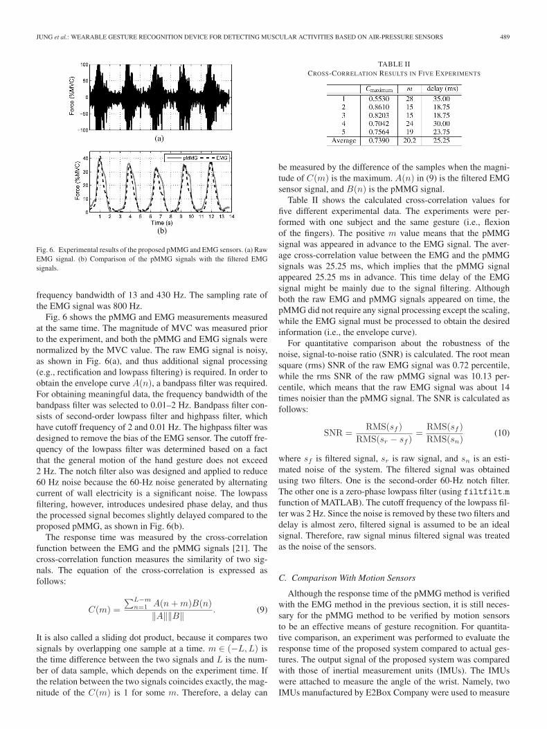
Fig. 6. Experimental results of the proposed pMMG and EMG sensors. (a) RawEMG signal. (b) Comparison of the pMMG signals with the filtered EMGsignals.
frequency bandwidth of 13 and 430 Hz. The sampling rate ofthe EMG signal was 800 Hz.
Fig. 6 shows the pMMG and EMG measurements measuredat the same time. The magnitude of MVC was measured priorto the experiment, and both the pMMG and EMG signals werenormalized by the MVC value. The raw EMG signal is noisy,as shown in Fig. 6(a), and thus additional signal processing(e.g., rectification and lowpass filtering) is required. In order toobtain the envelope curve A(n), a bandpass filter was required.For obtaining meaningful data, the frequency bandwidth of thebandpass filter was selected to 0.01–2 Hz. Bandpass filter con-sists of second-order lowpass filter and highpass filter, whichhave cutoff frequency of 2 and 0.01 Hz. The highpass filter wasdesigned to remove the bias of the EMG sensor. The cutoff fre-quency of the lowpass filter was determined based on a factthat the general motion of the hand gesture does not exceed2 Hz. The notch filter also was designed and applied to reduce60 Hz noise because the 60-Hz noise generated by alternatingcurrent of wall electricity is a significant noise. The lowpassfiltering, however, introduces undesired phase delay, and thusthe processed signal becomes slightly delayed compared to theproposed pMMG, as shown in Fig. 6(b).
The response time was measured by the cross-correlationfunction between the EMG and the pMMG signals [21]. Thecross-correlation function measures the similarity of two sig-nals. The equation of the cross-correlation is expressed asfollows:
C(m) =
∑L−mn=1 A(n+m)B(n)
‖A‖‖B‖ . (9)
It is also called a sliding dot product, because it compares twosignals by overlapping one sample at a time. m ∈ (−L,L) isthe time difference between the two signals and L is the num-ber of data sample, which depends on the experiment time. Ifthe relation between the two signals coincides exactly, the mag-nitude of the C(m) is 1 for some m. Therefore, a delay can
TABLE IICROSS-CORRELATION RESULTS IN FIVE EXPERIMENTS
be measured by the difference of the samples when the magni-tude of C(m) is the maximum. A(n) in (9) is the filtered EMGsensor signal, and B(n) is the pMMG signal.
Table II shows the calculated cross-correlation values forfive different experimental data. The experiments were per-formed with one subject and the same gesture (i.e., flexionof the fingers). The positive m value means that the pMMGsignal was appeared in advance to the EMG signal. The aver-age cross-correlation value between the EMG and the pMMGsignals was 25.25 ms, which implies that the pMMG signalappeared 25.25 ms in advance. This time delay of the EMGsignal might be mainly due to the signal filtering. Althoughboth the raw EMG and pMMG signals appeared on time, thepMMG did not require any signal processing except the scaling,while the EMG signal must be processed to obtain the desiredinformation (i.e., the envelope curve).
For quantitative comparison about the robustness of thenoise, signal-to-noise ratio (SNR) is calculated. The root meansquare (rms) SNR of the raw EMG signal was 0.72 percentile,while the rms SNR of the raw pMMG signal was 10.13 per-centile, which means that the raw EMG signal was about 14times noisier than the pMMG signal. The SNR is calculated asfollows:
SNR =RMS(sf )
RMS(sr − sf )=
RMS(sf )
RMS(sn)(10)
where sf is filtered signal, sr is raw signal, and sn is an esti-mated noise of the system. The filtered signal was obtainedusing two filters. One is the second-order 60-Hz notch filter.The other one is a zero-phase lowpass filter (using filtfilt.mfunction of MATLAB). The cutoff frequency of the lowpass fil-ter was 2 Hz. Since the noise is removed by these two filters anddelay is almost zero, filtered signal is assumed to be an idealsignal. Therefore, raw signal minus filtered signal was treatedas the noise of the sensors.
C. Comparison With Motion Sensors
Although the response time of the pMMG method is verifiedwith the EMG method in the previous section, it is still neces-sary for the pMMG method to be verified by motion sensorsto be an effective means of gesture recognition. For quantita-tive comparison, an experiment was performed to evaluate theresponse time of the proposed system compared to actual ges-tures. The output signal of the proposed system was comparedwith those of inertial measurement units (IMUs). The IMUswere attached to measure the angle of the wrist. Namely, twoIMUs manufactured by E2Box Company were used to measure
490 IEEE TRANSACTIONS ON INDUSTRIAL INFORMATICS, VOL. 11, NO. 2, APRIL 2015
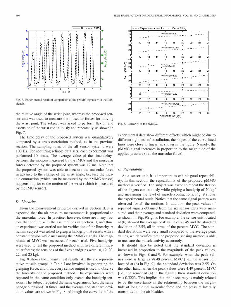
Fig. 7. Experimental result of comparison of the pMMG signals with the IMUsignals.
the relative angle of the wrist joint, whereas the proposed sen-sor unit was used to measure the muscular forces for movingthe wrist joint. The subject was asked to perform flexion andextension of the wrist continuously and repeatedly, as shown inFig. 7.
The time delay of the proposed system was quantitativelycompared by a cross-correlation method, as in the previoussection. The sampling rates of the all sensor systems were100 Hz. For acquiring reliable data sets, each experiment wasperformed 10 times. The average value of the time delaysbetween the motions measured by the IMUs and the muscularforces detected by the proposed system was 17 ms. Note thatthe proposed system was able to measure the muscular forcein advance to the change of the wrist angle, because the mus-cle contraction (which can be measured by the pMMG sensor)happens in prior to the motion of the wrist (which is measuredby the IMU sensor).
D. Linearity
From the measurement principle derived in Section II, it isexpected that the air pressure measurement is proportional tothe muscular force. In practice, however, there are many fac-tors that conflict with the assumptions in Section II, and thus,an experiment was carried out for verification of the linearity. Ahuman subject was asked to grasp a handgrip that resists with aconstant tension while measuring the pMMG signals. The mag-nitude of MVC was measured for each trial. Five handgripswere used to test the proposed method with five different mus-cular forces; the tensions of the fives handgrips were 10, 12, 20,22, and 25 kgf.
Fig. 8 shows the linearity test results. All the six represen-tative muscle groups in Table I are involved in generating thegrasping force, and thus, every sensor output is used to observethe linearity of the proposed method. The experiments wererepeated in the same condition only except the handgrip ten-sions. The subject repeated the same experiment (i.e., the samehandgrip tension) 10 times, and the average and standard devi-ation values are shown in Fig. 8. Although the curve fits of the
Fig. 8. Linearity of the pMMG.
experimental data show different offsets, which might be due todifferent tightness of installation, the slopes of the curve-fittedlines were close to linear, as shown in the figure. Namely, thepMMG signal increases in proportion to the magnitude of theapplied pressure (i.e., the muscular force).
E. Repeatability
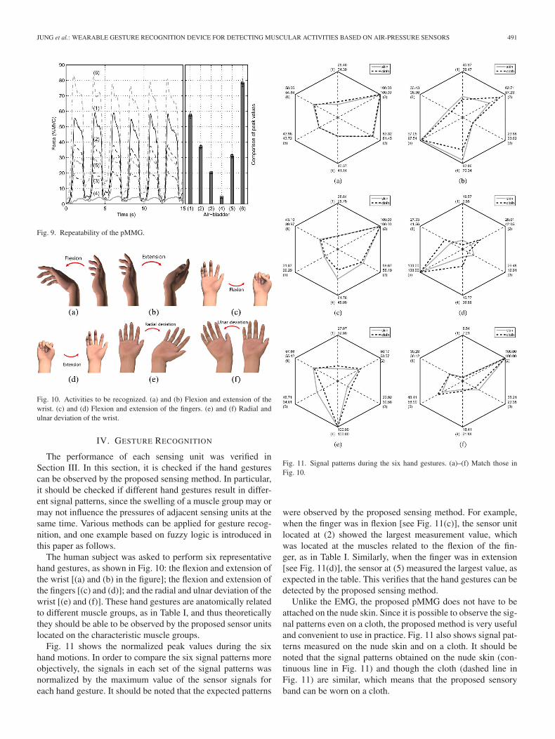
As a sensor unit, it is important to exhibit good repeatabil-ity. In this section, the repeatability of the proposed pMMGmethod is verified. The subject was asked to repeat the flexionof the fingers continuously while griping a handgrip of 20 kgfand measuring the level of muscle contractions. Fig. 9 showsthe experimental result. Notice that the same signal pattern wasobserved for all the motions. In addition, the peak values ofrepeated signals obtained from the six sensor units were mea-sured, and their average and standard deviation were compared,as shown in Fig. 9(right). For example, the sensor unit locatedat (6) showed the average peak value of 78.49 and the standarddeviation of 2.55, all in terms of the percent MVC. The stan-dard deviations were very small compared to the average peakvalues, which verifies that the proposed sensing method is ableto measure the muscle activity accurately.
It should also be noted that the standard deviation isincreased in proportion to the magnitude of the peak values,as shown in Figs. 8 and 9. For example, when the peak val-ues were as large as 78.49 percent MVC [i.e., the sensor unitlocated at (6) in Fig. 9], their standard deviation was 2.55. Onthe other hand, when the peak values were 4.49 percent MVC[i.e., the sensor at (4) in the figure], their standard deviationwas 0.3223. This implies that the inaccuracy is mainly relatedto by the uncertainty in the relationship between the magni-tude of longitudinal muscular force and the pressure laterallytransmitted to the air-bladder.
JUNG et al.: WEARABLE GESTURE RECOGNITION DEVICE FOR DETECTING MUSCULAR ACTIVITIES BASED ON AIR-PRESSURE SENSORS 491
Fig. 9. Repeatability of the pMMG.
Fig. 10. Activities to be recognized. (a) and (b) Flexion and extension of thewrist. (c) and (d) Flexion and extension of the fingers. (e) and (f) Radial andulnar deviation of the wrist.
IV. GESTURE RECOGNITION
The performance of each sensing unit was verified inSection III. In this section, it is checked if the hand gesturescan be observed by the proposed sensing method. In particular,it should be checked if different hand gestures result in differ-ent signal patterns, since the swelling of a muscle group may ormay not influence the pressures of adjacent sensing units at thesame time. Various methods can be applied for gesture recog-nition, and one example based on fuzzy logic is introduced inthis paper as follows.
The human subject was asked to perform six representativehand gestures, as shown in Fig. 10: the flexion and extension ofthe wrist [(a) and (b) in the figure]; the flexion and extension ofthe fingers [(c) and (d)]; and the radial and ulnar deviation of thewrist [(e) and (f)]. These hand gestures are anatomically relatedto different muscle groups, as in Table I, and thus theoreticallythey should be able to be observed by the proposed sensor unitslocated on the characteristic muscle groups.
Fig. 11 shows the normalized peak values during the sixhand motions. In order to compare the six signal patterns moreobjectively, the signals in each set of the signal patterns wasnormalized by the maximum value of the sensor signals foreach hand gesture. It should be noted that the expected patterns
Fig. 11. Signal patterns during the six hand gestures. (a)–(f) Match those inFig. 10.
were observed by the proposed sensing method. For example,when the finger was in flexion [see Fig. 11(c)], the sensor unitlocated at (2) showed the largest measurement value, whichwas located at the muscles related to the flexion of the fin-ger, as in Table I. Similarly, when the finger was in extension[see Fig. 11(d)], the sensor at (5) measured the largest value, asexpected in the table. This verifies that the hand gestures can bedetected by the proposed sensing method.
Unlike the EMG, the proposed pMMG does not have to beattached on the nude skin. Since it is possible to observe the sig-nal patterns even on a cloth, the proposed method is very usefuland convenient to use in practice. Fig. 11 also shows signal pat-terns measured on the nude skin and on a cloth. It should benoted that the signal patterns obtained on the nude skin (con-tinuous line in Fig. 11) and though the cloth (dashed line inFig. 11) are similar, which means that the proposed sensoryband can be worn on a cloth.

492 IEEE TRANSACTIONS ON INDUSTRIAL INFORMATICS, VOL. 11, NO. 2, APRIL 2015
A. Auto-Calibration
The location of the muscles and the change of the cross-sectional area are all different for each person. For this reason,an auto-calibration process is necessary. Note that the coeffi-cient in (8) is dependent on the user’s physical condition (e.g.,the volume of muscles, the circumference of the forearm, andso on) and wearing conditions (e.g., the tightness of an arm-band, the presence of a cloth between the skin and the sensor,and so on). In the experiments of this paper, every subject wasasked to squeeze as much as possible, so that the muscles weremaximally contracted. During the execution, the level of MVCwas measured for each muscle for normalizing sensor signals.The auto-calibration process greatly reduced uncertainty in thescaling factors for each trial and improved the success rate ofthe gesture recognition.
B. Fuzzy Logic: Signal Normalization
For autonomous gesture recognition in real time, the patternsin Fig. 10 are represented as recognition rule bases, and fuzzylogic is utilized to recognize the current gesture. The mem-bership functions of the proposed fuzzy recognition algorithmare the functions of the pressures measured by the air pressuresensors and are calculated as follows.
When the sum of the air pressure measurements is larger thana threshold, all the measurement values from six air pressuresensors are normalized by the largest value output among them.Otherwise, all the measurement values are set to 0. By this nor-malization, the measurement of the sensor unit is converted tothe ratio of the air pressure, which is ranged from 0 to 1. Thisnormalization scheme is formulated as
yi(k) =
{yi(k)
max(yi(k)), if
∑6i=1 yi(k) ≥ λ
0, otherwise(11)
where yi(k) is the measurement of ith sensor at kth sam-pling instance, yi(k) is the normalized magnitude, and λ is athreshold value.
C. Fuzzification
The membership functions are designed as hyperbolic tan-gent functions of the normalized pressure values. Each airbladder has three membership functions: 1) a low phase mem-bership function; 2) a middle phase membership function; and3) a high phase membership function. The output of each func-tion represents the likelihood of the air pressure measurement,i.e., pMMG, to be in each phase, i.e., low, middle, and high.
These membership functions are illustrated in Fig. 12. As inFig. 12, the shape of the membership function is specified bythree parameters: 1) εi; 2) αi; and 3) si, where εi specifies thenormalized signal value for the middle membership function tobe 1, αi specifies the range where the middle membership func-tion has values higher 0.5, and si determines the slope duringtransition, which is related to the sensitivity of the hyperbolictangent.
Fig. 12. Fuzzy membership function.
TABLE IIIRULE BASE OF FUZZY LOGIC
N/A: Not applied
Equations (12)–(14) are the definitions of three membershipfunctions with these parameters
li(k) =
{12 (1− tanh(si(yi(k)− εi + αi))), for yi(k) < εi
0, for yi(k) ≥ εi
(12)
mi(k) =
{1− li(k), for yi(k) < εi
1− hi(k), for yi(k) ≥ εi(13)
hi(k) =
{0, for yi(k) < εi12 (1 + tanh(si(yi(k)− εi − αi))), for yi(k) ≥ εi.
(14)
All the parameters εi, αi, and si were determined throughoptimization with experimental data, i.e., the parameters areoptimized to minimize the two-norm error of the gesture recog-nition results.
D. Rule Bases
The rule base of the fuzzy logic is designed as in Table IIIbased on the membership functions. The rule base was mainlydetermined by the role of muscles for each gesture and theair bladders corresponding to the muscles. For example, in thecase of finger flexion, the rule base for the air-bladder at (3) isdesigned as high phase since the role of flexor carpi radials iscritical, and the rule bases for the air-bladders at (2) and (4) aredesigned as middle phase since the flexor digitorum and exten-sor carpi radials are to be effected by the expansion of flexorcarpi radials.
The fuzzy membership value μi, which is the likelihood ofeach gesture, is calculated by the Larsen product implicationmethod [22]. Larsen product implication method is representedby the production of membership functions. The order of thesubscripts of the membership function value is the same as in
JUNG et al.: WEARABLE GESTURE RECOGNITION DEVICE FOR DETECTING MUSCULAR ACTIVITIES BASED ON AIR-PRESSURE SENSORS 493
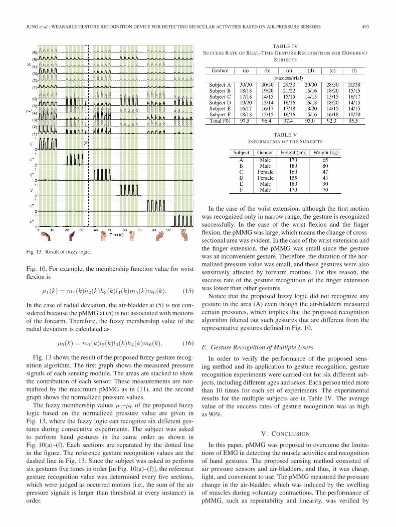
Fig. 13. Result of fuzzy logic.
Fig. 10. For example, the membership function value for wristflexion is
μ1(k) = m1(k)h2(k)h3(k)l4(k)m5(k)m6(k). (15)
In the case of radial deviation, the air-bladder at (5) is not con-sidered because the pMMG at (5) is not associated with motionsof the forearm. Therefore, the fuzzy membership value of theradial deviation is calculated as
μ5(k) = m1(k)l2(k)l3(k)h4(k)m6(k). (16)
Fig. 13 shows the result of the proposed fuzzy gesture recog-nition algorithm. The first graph shows the measured pressuresignals of each sensing module. The areas are stacked to showthe contribution of each sensor. These measurements are nor-malized by the maximum pMMG as in (11), and the secondgraph shows the normalized pressure values.
The fuzzy membership values μ1–μ6 of the proposed fuzzylogic based on the normalized pressure value are given inFig. 13, where the fuzzy logic can recognize six different ges-tures during consecutive experiments. The subject was askedto perform hand gestures in the same order as shown inFig. 10(a)–(f). Each sections are separated by the dotted linein the figure. The reference gesture recognition values are thedashed line in Fig. 13. Since the subject was asked to performsix gestures five times in order [in Fig. 10(a)–(f)], the referencegesture recognition value was determined every five sections,which were judged as occurred motion (i.e., the sum of the airpressure signals is larger than threshold at every instance) inorder.
TABLE IVSUCCESS RATE OF REAL-TIME GESTURE RECOGNITION FOR DIFFERENT
SUBJECTS
TABLE VINFORMATION OF THE SUBJECTS
In the case of the wrist extension, although the first motionwas recognized only in narrow range, the gesture is recognizedsuccessfully. In the case of the wrist flexion and the fingerflexion, the pMMG was large, which means the change of cross-sectional area was evident. In the case of the wrist extension andthe finger extension, the pMMG was small since the gesturewas an inconvenient gesture. Therefore, the duration of the nor-malized pressure value was small, and these gestures were alsosensitively affected by forearm motions. For this reason, thesuccess rate of the gesture recognition of the finger extensionwas lower than other gestures.
Notice that the proposed fuzzy logic did not recognize anygesture in the area (A) even though the air-bladders measuredcertain pressures, which implies that the proposed recognitionalgorithm filtered out such gestures that are different from therepresentative gestures defined in Fig. 10.
E. Gesture Recognition of Multiple Users
In order to verify the performance of the proposed sens-ing method and its application to gesture recognition, gesturerecognition experiments were carried out for six different sub-jects, including different ages and sexes. Each person tried morethan 10 times for each set of experiments. The experimentalresults for the multiple subjects are in Table IV. The averagevalue of the success rates of gesture recognition was as highas 90%.
V. CONCLUSION
In this paper, pMMG was proposed to overcome the limita-tions of EMG in detecting the muscle activities and recognitionof hand gestures. The proposed sensing method consisted ofair pressure sensors and air-bladders, and thus, it was cheap,light, and convenient to use. The pMMG measured the pressurechange in the air-bladder, which was induced by the swellingof muscles during voluntary contractions. The performance ofpMMG, such as repeatability and linearity, was verified by

494 IEEE TRANSACTIONS ON INDUSTRIAL INFORMATICS, VOL. 11, NO. 2, APRIL 2015
experiments in this paper. Also, it was shown that the six rep-resentative hand gestures could be detected by a fuzzy logicalgorithm automatically. An auto-calibration made the overallsystem more robust. The performance of the proposed ges-ture recognition system was verified with multiple subjects bychecking the success rate of gesture recognition.
In the future work, an IMU will be utilized to remove theeffect of the forearm motions for improving the success rate ofgesture recognition. In addition, the effect of the swelling of theclose muscle groups will be considered in the following paper.
REFERENCES
[1] Governors Highway Safety Association. Distracted Driving: WhatResearch Shows and What States Can Do, 2014 [Online]. Available:http://ghsa.org/html/publications/sfdist.html
[2] K. Kasaoka and Y. Sankai, “Predictive control estimating operator’sintention for stepping-up motion by exo-skeleton type power assist sys-tem HAL,” in Proc. IEEE/RSJ Int. Conf. Intell. Robots Syst., 2001, vol. 3,pp. 1578–1583.
[3] H. Liu, “Exploring human hand capabilities into embedded multifingeredobject manipulation,” IEEE Trans. Ind. Informat., vol. 7, no. 3, pp. 389–398, Aug. 2011.
[4] K. R. Wheeler and C. C. Jorgensen, “Gestures as input: Neuroelectricjoysticks and keyboards,” IEEE Trans. Pervasive Comput., vol. 2, no. 2,pp. 56–61, Apr./Jun. 2003.
[5] M. Khezri and M. Jahed, “A neuro-fuzzy inference system for sEMG-based identification of hand motion commands,” IEEE Trans. Ind.Electron., vol. 58, no. 5, pp. 1952–1959, May 2011.
[6] Y. Oonishi, S. Oh, and Y. Hori, “A new control method for power-assistedwheelchair based on the surface myoelectric signal,” IEEE Trans. Ind.Electron., vol. 57, no. 9, pp. 3191–3196, Sep. 2010.
[7] X. Zhang et al., “On design and implementation of neural-machineinterface for artificial legs,” IEEE Trans. Ind. Informat., vol. 8, no. 2,pp. 418–429, May 2012.
[8] Thalmic Labs. Myo Gesture Control Armband, 2014 [Online]. Available:https://www.thalmic.com/en/myo/
[9] B. Comby, G. Chevalier, and M. Bouchoucha, “A new method for themeasurement of tremor at rest,” Int. Arch. Physiol. Biochem. Biophys.,vol. 100, no. 1, pp. 73–78, 1992.
[10] Y. Zheng, Z. Yang, W. Cao, and C. Xia, “Hand-motion patterns recog-nition based on mechanomyographic signal analysis,” in Proc. Int. Conf.Future BioMed. Inf. Eng., 2009. pp. 21–24.
[11] N. Alves and T. Chau, “Recognition of forearm muscle activity by con-tinuous classification of multi-site mechanomyogram signals,” in Proc.IEEE Int. Conf. Eng. Med. Biol. Soc., 2010, pp. 3531–3534.
[12] A. Courteville, T. Gharbi, and J.-Y Cornu, “MMG measurement: Ahigh-sensitivity microphone-based sensor for clinical use,” IEEE Trans.Biomed. Eng., vol. 45, no. 2, pp. 145–150, Feb. 1998.
[13] M. Watakabe, K. Mita, K. Akataki, and Y. Itoh, “Mechanical behaviour ofcondenser microphone in mechanomyography,” in Proc. Int. Conf. Med.Biol. Eng. Comput., 2001, vol. 39, pp. 195–201.
[14] P. Lukowicz, F. Hanser, C. Szubski, and W. Schobersberger, “Detectingand interpreting muscle activity with wearable force sensors,” in Proc.4th Int. Conf. Pervasive Comput., 2006, pp. 101–116.
[15] M. Kreil, G. Ogris, and P. Lukowicz, “Muscle activity evaluation usingforce sensitive resistors,” in Proc. Int. Symp. Med. Devices Biosens., 2008,pp. 107–110.
[16] G. Ogris, M. Kreil, and P. lukowicz, “Using FSR based muscule activitymonitoring to recognize manipulative arm gestures,” in Proc. IEEE Int.Symp. Wearable Comput., 2007, pp. 45–48.
[17] K. Kong and M. Tomizuka, “A gait monitoring system based on airpressure sensors embedded in a shoe,” IEEE/ASME Trans. Mechatron.,vol. 14, no. 3, pp. 358–370, Jun. 2009.
[18] G.-T. Bae, J.-B. Song, and B.-S. Kim, “Imitation of human motionbased on variable stiffness actuator and muscle stiffness sensor,” in Proc.IEEE/ASME Int. Conf. Adv. Intell. Mechatron., 2013, pp. 1016–1020.
[19] J. Gordon and C. Ghez, “EMG patterns in antagonist muscles during iso-metric contraction in man: Relations to response dynamics,” Exp. BrainRes., vol. 55, pp. 167–171, 1984.
[20] H. E. Huxley, “The mechanism of muscular contraction,” Science, vol.164, no. 3886, pp. 1356–1365, 1969.
[21] C. H. Knapp and G. C. Carter, “The generalized correlation method forestimation of time delay,” IEEE Trans. Acoust. Speech Signal Process.,vol. 24, no. 4, pp. 320–327, Aug. 1976.
[22] P. M. Larsen, “Industrial applications of fuzzy logic control,” Int. J. ManMach. Stud., vol. 12, no. 1, pp. 3–10, 1980.
Pyeong-Gook Jung (S’13) received the B.S. andM.S. degrees in mechanical engineering from SogangUniversity, Seoul, South Korea, in 2013 and 2015,respectively. He is currently pursuing the Ph.D.degree at the same university.
Mr. Jung was the recipient of the BestUndergraduate Student Paper Award from the27th Institute of Control, Robotics, and Systems(ICROS), Gyeonggi-do, Korea.
Gukchan Lim received the B.Eng. and M.S. degreesin computer engineering from Kyunghee University,Seoul, South Korea, in 1990 and 2001, respectively.
In 2001, he joined the LG Electronics MobileCommunication Company, Seoul, South Korea. Since2009, he has been the Senior Research Engineer forprior sensor technology. He holds more than 150Korea/International patents related to mobile system,hardware architecture, and sensor applications.
Seonghyok Kim received the B.S.E. and M.S.degrees in electrical engineering from Seoul NationalUniversity, Seoul, South Korea, in 1996 and 1998,respectively, and the Ph.D. degree in electrical engi-neering and computer science from the same univer-sity in 2002.
After joining the LG Electronics Institute ofTechnology, Seoul, Korea as a Senior ResearchEngineer in 2002, he participated in the design andfabrication of a wide variety of microelectromechani-cal systems (MEMS) devices for portable electronics.
In 2005, he joined the MicroSensors and MicroActuators Laboratory (MSMA),Georgia Institute of Technology, Atlanta, GA, USA, as a Post-Doctoral Fellow,and led the PowerMEMS Research Group at the MSMA Laboratory. From2007 to 2010, he led various research projects encompassing microsensors andactuators, nanomaterials, power passives, bio-medical microdevices, etc., as aResearch Engineer II. Since 2010, he has been the Principal Research Engineerwith LG Electronics Mobile Communication Company, Seoul, where he hasbeen pioneering the application of emerging technologies for mobile electronicdevices. He has authored more than 50 peer-reviewed journal and conferencearticles, and holds more than 30 Korean/International patents.
Kyoungchul Kong (S’04–M’09) received the B.Eng.degree in mechanical engineering (summa cum laude)in 2004, the B.S. degree in physics in 2004, and theM.S. degree in mechanical engineering in 2006 fromSogang University, Seoul, South Korea, and the Ph.D.degree in mechanical engineering from the Universityof California, Berkeley, CA, USA, in 2009.
In 2011, he joined the Department of MechanicalEngineering, Sogang University, Seoul. He hasauthored or co-authored more than 70 technical arti-cles in journals and conference proceedings in the
area of mechatronics, including locomotive robotics and human robot inter-active systems. His research interests include design, modeling, and control ofmechatronic systems with an emphasis on locomotion and mobility of roboticsystems.
Dr. Kong was the recipient of the Best Student Paper Award at the IEEEConference on Advanced Intelligent Mechatronics (AIM) in 2008, and the BestPaper Award in the Division of Dynamic Systems and Control at the Koreansociety of mechanical engineers (KSME) Annual Conference in 2005.