A W. SAMS PUBLICATION JULY PF Reporter
92
A HOWARD W. SAMS PUBLICATION JULY 1965150,i PF Reporter the magazine of electronic servicing ::.::Gil Q-_. s - e *...,e'. 3 . + i.l\ c: a a. Iss..-.. ¡ l CAI! Av. w 5 i H. ¡ü/ . ÿi tie -__se . l. - 81< R ' l\, ,.p.. / 1 , psi .ia? 1i Ó" / v' - i yV'y Ili 11,0'. /, // .. ÿ P. \ .o, `i tx Mq _ BMW 2/0 . 1\ - 1- . tl.lM\t Bella ._ r 'U;UJ 'A11J N.JNY 3AV 301SbJAf f111 'Ad3S Al p 'Cyb SIAYU 'ry "ron 997 1 q71 I l V \ i Special Antenna Section Overcoming Wind -Load Effects Maintenance of Antennas and Towers Phasing Multiple -Antenna Systems Plus ether servicing features www.americanradiohistory.com
Transcript of A W. SAMS PUBLICATION JULY PF Reporter

A HOWARD W. SAMS PUBLICATION JULY 1965150,i
PF Reporter the magazine of electronic servicing
::.::Gil Q-_. s -
e *...,e'. 3
. + i.l\ c: a a. Iss..-.. ¡ l CAI! Av. w 5 i H. ¡ü/ . ÿi tie -__se . l. -
81< R . ' l\, ,.p.. / 1 , psi .ia? 1i Ó" / v' - i yV'y Ili 11,0'. /, // .. ÿ P. \ .o, `i
tx Mq _ BMW 2/0 . 1\ - 1- . tl.lM\t Bella ._ r
'U;UJ 'A11J N.JNY 3AV 301SbJAf f111
'Ad3S Al p 'Cyb SIAYU 'ry "ron
997 1 q71 I l V
\
i
Special Antenna Section
Overcoming Wind -Load Effects
Maintenance of Antennas and Towers
Phasing Multiple -Antenna Systems
Plus ether servicing features www.americanradiohistory.com

THE BIG PRODUCTS ...THE BIG PROGRAM...
THE BIG BACK-UP...FOR DIG SUMMER PROFITS Here's a strong, ready -to -work program that'll help you take advantage of the summer months for special savings and extra sales.
Old Man Winter, Color TV, and the new Jerrold Coloraxial reception system have given you a ready-made new market for summer antenna installations.
To make sure your summertime Coloraxial push is a
BIG success, we've prepared a series of ad mats for you. Use them with co-op ad money that Jerrold and your distributor have reserved for you. These ads, in your local paper over your name, emphasize that service is
even faster in the summer-and it costs less. With longer daylight time to make more outdoor installations, you can even pass on part of your savings to your customers.
In the new world of color TV, the Jerrold Coloraxial Reception Specialist will be a big man in his community. You can qualify now, and get shirt emblems and truck decals that proclaim you the Coloraxial TV expert in your area. Talk it over with your Jerrold distributor today, and start reaping the profits on our BIG SUMMERTIME SPECIALS.
JERROLD
BIG SUMMERTIME SPECIALS ON
Coloraxial* Powermate Paralog Paracyl Colorguard
1
M
August 15 is the deadline! See your Jerrold distributor today and take advantage of the great specials available on the popular Jerrold
line ... antennas, preamplifiers, amplified coup- lers, unamplified couplers, and Coloraxial con- version kits.
2 While you're there, make it a point to discuss how easy it is to place hard -sell Coloraxial ads in your local newspaper featuring you as
the Jerrold Coloraxial Reception Specialist.
3 Summer business can be great for the dealer who promotes! New Jerrold Coloraxial recep- tion systems and Summer Specials break
tradition ... give you the sales boosters you need for greater business and profits. 'Trademark
DISTRIBUTOR SALES DIVISION
JERROLD ELECTRONICS CORPORATION 15TH & LEHIGH AVENUE PHILADELPHIA, PA. 19132
Circle 1 on literature card www.americanradiohistory.com

....PRfV1EWS of new sets Admiral
HORI2 EFFICIENCY
AXIAL TILT ADJUSTMENT
I AGC CO_OR VER" ( CIRCUIT aD.JìT KILLER LIN BREAKER
RWE BWE GREEN RED
SCREEN DRIVE ;GREEN SCREEN
PICTURE GREEN NORMAL- TUBE BIAS DRIVE SERVICL
SWITCH
BOARD CONSISTING OF BLACK H WHITE TRACKING CCWITROLS
B DEMOD
6GY6
VERT FIN GAIS CUSHION
DIORIZI BIAS
'"imi_
Y` 11
e'17
? 58 -MC OSC- 4 DE100 BURST »4'- COLOR KILER - REACTANCE CONTROL 6G 6 2ND BANDMES AME 1ST BANDPA' S AMP
6GH8A 6GH8A
PHASE DET-
KILLER DET
6J 08
Admiral Model LG5315
Chassis G-1263-1
"Giant -size color" might be the best way to describe the above -pictured 25" Admiral color receiver. In most re- spects, this set is the same as the com- pany's 21" models. However, the larger rectangular picture tube, a 25AP22, has necessitated a few circuit modifications along with an additional circuit that corrects for pincushioning at the top, bottom, and edges of the raster. Another new feature, automatic degaussing, is also found in this set.
An axial tilt adjustment is located beneath the yoke and provides a minor adjustment for the blue at the edges of the screen. If necessary, this tilt adjust- ment should be made after receiver con- vergence. Loosen the yoke -positioning clamps and turn the 1/4" screw until the blue vertical lines coincide with the red and green vertical lines near the edges of the raster.
The adjustments for correcting verti- cal or horizontal pincushioning are in an individual subchassis mounted on the left side of the main chassis (when viewed from the rear). These adjust- ments should be performed using a crosshatch pattern on the screen. The adjustment procedure for vertical cor- rection is as follows: Turn the vertical gain control fully clockwise; adjust the vertical -phase transformer until the hori- zontal lines at the top and bottom of the screen are symmetrically rounded or bowed; adjust the vertical -gain control until these lines are straight. For hori- zontal correction, connect a VTVM from the center lug of the horizontal -bias con- trol to ground, and adjust the control for a 4 -volt DC reading on the meter.
The low -voltage power supply in this transformer -powered set is a little un- common. It uses four silicon rectifiers wired in a bridge rectifier network.
If you have difficulty in obtaining the correct purity, check the filter choke in the power supply. If this choke has two yellow wires, try reversing the connec- tions. Early production runs used a choke with two yellow leads, and if these are connected improperly, polarization of the choke is incorrect. In later pro- duction, a choke with one black and one yellow lead is used to alleviate this prob- lem.
PF REPORTER, July, 1965. Vol. Indianapolis 6, Indiana. Second-class Canada: $5.00, $8.00, $10.00. Other
15, No. 7. PF postage paid at countries: $6.00,
REPORTER is published monthly by Howard W. Sams & Co., Inc., 4300 W. 62nd Indianapolis, Indiana. 1, 2, & 3 year subscription prices; U.S.A., its possessions and $10.00, $13.00. Current single issues 50¢ each; back issues 65¢ each.
July, 1965/PF REPORTER 1
www.americanradiohistory.com

Philco PREVIEWS of new sets
Philco Model N1200BR
Here's Philco's latest small -screen portable-a 12" set equipped with a built-in monopole antenna, earphone jack, and carrying handle. The chassis in this Japanese import has a different physical appearance along with several unfamiliar tube types.
A total of 14 tubes is used, including the CRT-type A31-12W-and those in the VHF tuner. The chassis consists of three individual printed circuit boards. There are two small boards; one con- tains the vertical -sweep circuits, the other the horizontal AFC/oscillator. The remainder of the circuitry, with the ex- ception of the low- and high -voltage power supplies and horizontal -output stage, is on the large printed board.
The two -stage video IF strip uses a 6EH7 and 6EJ7 as first and second IF amplifiers, respectively, followed by a 15CW5 as the video output. An 8A8 is used as sound IF amplifier/sync sepa- rator; a 16A8 serves as audio output/ sync amplifier. The audio detector uses the familiar 6DT6. The vertical section has an 18GV8 operating as multivibra- tor/output. The horizontal section con- sists of a 17A8 horizontal AFC/oscilla- tor and a 50JY6 in the output stage. The high -voltage rectifier is a 1X2B, and the damper is a 34R3.
The low -voltage power supply con- tains one silicon rectifier, which is pro- tected by both a 4.7 -ohm surge -limiting resistor and a 2 -amp line fuse. The series -parallel filament string has a tapped dropping resistor. AC voltage to the filaments of the horizontal -oscillator, output, and damper tubes is reduced by the 43 -ohm section of this resistor, while the filament voltage to the other tubes is
reduced by both the 43 -ohm section and a 22 -ohm section.
AGC voltage is derived from the out- put of the video detector, and an RF AGC switch is employed in the tuner AGC circuit. The switch connects either 10 or 27 megohms from the RF AGC line to B + . Width is adjustable by means of a width coil, and the focus may be varied by connecting pin 4 of the pic- ture tube to either B +, boost, or ground.
4.7 OHM SURGE
LIMITING
FILAMENT
DROPPING
RESISTOR
LINE FUE 2 AMP
VERT
'HOLD
HORIZ HOLD
VERT
LIN
HORIZ OSC
COIL
HORIZ AFC- OSC I LLATOR
17A8
HORIZONTAL
OSCILLATOR BOARD
VERT KIT - OUTPUT
18Gu6
VERTICAL MULT IV I BRATOR-
OUTPUT BOARD
UHF TUNER
VHF TUNER
1X28
HV REGT
3483 DAMPER
2 PF REPORTER/July, 1965
www.americanradiohistory.com

.......::.........PRE l'lt4' I4S of new sets Sears
VIDEO IF
SECTION
HEIGHT
VERT
LIN
AGC
COLOR
KILLER
CRT SCREEN
SWITCH
(SEE TEXT)
/FOCUS
CIRCUIT 'BREAKER
DELAY LINE
/ B -Y DEMOD R -Y DElMGD G -Y DEMOD
6R -P22 6R -P22 6R-IP22
HV RU CATHODE JUMPER
R -G VERT
LINES L SIDE
R -G VERT
LINES R SIDE
R -G HORIZ LINES R SIDE
R G HORIZ LINES L SIDE
I
BLUE HORIZ LINES R SIDE
R -G VERT
LINES TOP
R -G VERT LIKES BOTTOM
A 'E !`.-¡
.
`¡r // tirurw.l
BLUE HORIZ LINES L SIDE
BLUE HORIZ LINES TOP
RED
BACKGROUND RED
SCREEN
GREEN
BACKGROUND
GREEN
SCREEN
BLUE
SCREEN
BLUE HORIZ BLUE LINES BO7IGM BACKGROUND
RATIO DET
DIODES B+ RECTIFIERS COLOR
BALANCE
3.58 -MC CRYSTAL
Sears Chassis 562.10102
Model 5170
This is Sears' small -screen (16") color receiver, housed in a wood cabinet and using a 400KB22 picture tube. The set is manufactured in Japan by Toshiba and imported and sold in this country by Sears Roebuck and Company. Basically, the circuitry is quite similar to that used in color receivers made in the United States. However, there are some differ- ences worth noting.
In the color circuits, there are a two - stage chroma bandpass amplifier and three independent demodulators; 6R -P22 tubes are used to demodulate R -Y, B -Y, and G -Y separately. All the other tubes are common types, with the exception of the 5642 focus rectifier.
The convergence coils and controls, along with the screen and background controls, are located on an individual board. (This controls are labeled in one of the photos.) A five -position switch is provided to make purity and converg- ence adjustments easier. Three 100K resistors connected to the screen grids of the CRT may be connected separate- ly or jointly to ground to obtain the following raster colors on the screen: white, red and green, blue, green, or red. This receiver doesn't have a normal - service switch; therefore, gray -scale tracking is accomplished by using both the screen and background controls- one is provided for each gun.
This hand -wired, transformer -powered chassis has a conventional low -voltage power supply-two silicon rectifiers op- erating in a full -wave voltage -doubler circuit.
A plug and jumper arrangement is provided on top of the chassis for moni- toring high -voltage -regulator cathode current during horizontal -sweep adjust- ment. Merely remove the jumper and in- sert a milliammeter in the socket.
The sound -reject and color -balance controls are located beneath the chassis. The color -balance control is pointed out in the photo, and the sound -reject control is beneath the video -IF section.
July, 1965/PF REPORTER 3
www.americanradiohistory.com

Zenith PREVIEWS of new sets
Zenith Chassis 25MC33
Pictured above is Zenith's latest 21" color receiver. This one isn't changed drastically from earlier -model color sets, but it does have an additional circuit- automatic degaussing-along with some other interesting changes.
As in the past, the transformer -pow- ered chassis is completely hand -wired, including the convergence board. For speed and ease when converging the re- ceiver, the coils and controls are labeled red and green (R+G) horizontal lines top, bottom, left side, and right side; the same labeling applies to the red and green vertical lines and the blue horizon- tal lines. Thus, from the labeling you can determine what portion of the screen will be affected by adjusting a specific con- trol or coil.
A number of compactrons are used in this set, and as a result fewer tubes are required. Among these multi -purpose compactrons are the 6J10 sound IF am- plifier/discriminator/output, 6BA 1 1 sync separator/AGC keyer/vertical multivi- brator, and 6U10 horizontal AFC/oscil- lator/discharge. Although not a compac- tron, a 6KT8 is now used in the color - sync stages (replacing a 6GH8 used last year) as the 3.58 -mc oscillator and reac- tance control.
Low -voltage BI- is developed from a pair of silicon rectifiers connected in a full -wave, voltage -doubler circuit. The rectifiers are protected by a circuit break- er in series with the secondary winding of the power transformer.
Other semiconductors include the sig- nal diodes functioning as horizontal - phase detector, video detector, sound - sync detector, and convergence rectifier.
The customer operating controls are accessible by opening a door at the front right-hand corner of the set. Nor- mal -service and setup controls are on the rear apron of the chassis and are adjustable from the back of the receiver. Purity, convergence, and black -and - white tracking adjustments are performed in the same manner as on previous sets from this manufacturer. Should any ad- ditional adjustments or alignment be re- quired, follow the procedure in the serv- ice manual, or consult the appropriate PHOTOFACT folder.
CIRCUIT BREAKER
SOUND IF - DISC -OUTPUT
6J10
CONVERGENCE
RECTJFIER
VERTICAL OUTPUT
,.._ ' i' ,
3R GHTNES5
RANGE
SETUP -NORMAL SWITCH
G2 (SCREE+r
CONTROLS
HORIZ OUTPUT
6J S6
U BOTTOM VIEW 01 CONVERGENCE PANEL
HORIZ PHASE
DETECTOR
3.58MC
CRYSTAL LOW -VOLTAGE
RECTIFIERS
VERTICAL OUTFUI 6HE5
HORIZ AFC- OSC- DlSCH
61.110
FILTER
CHOKE
4 PF REPORTER/July, 1965
www.americanradiohistory.com

VIDEO ZPEED SERVICING Eeecetee See PHOTOFACT Set 710, Folder 2
Mfr: General Electric Chassis No. QY
Card No. GE QY-1
Section Affected: Pix and sound.
Symptoms: Video overload and buzz in sound; voltage at pin 5 of V1B (2nd VIF grid) is positive.
Cause: Primary -to -secondary short in video IF transformer.
What To Do: Replace L4.
Mfr: General Electric
Card No. GE QY-2
Section Affected: Sound.
Chassis No. QY
Symptoms: Volume decreases after set is on for a period of time.
Cause: Increased value of sound -IF cathode resistor.
What To Do: Replace R33 (680 ohms).
Mfr: General Electric
Card No. GE QY-3
Section Affected: Pix.
Chassis No. QY
Symptoms: Video overload; incorrect voltage on pin 1 of V2B (6JN8).
Cause: Grid -to -cathode resistor overheats and reduces in value.
What To Do: Replace R46 (56K).
July, 1965/PF REPORTER 5
www.americanradiohistory.com

VIDEO P E -D SERVICING
IP -5
FROM 1.2 meg HORIZ AFC
68K
HORIZ MUTT
a 8810
nov
4
5V
11K
5%
HORIZ STABILIZER
NI
Q' .0033
10%
135V
VERT MULT-VERT OUTPUT
v5 B 17JZ8
135V
BNB
º 50ma
1.2 meg 1004
HEIGHT 500K I40V
TI
.0018 2KV
1401
VERT DUI
See PHOTOFACT Set 710, Folder 2
Mfr: General Electric Chassis No. QY
Card No. GE QY-4
Section Affected: Horizontal sync.
Symptoms: Unstable horizontal hold.
Cause: Horizontal-multivibrator grid capacitor opens intermittently.
What To Do: Replace C49 (.005 mfd).
Mfr: General Electric Chassis No. QY
Card No. GE QY-5
Section Affected: Raster.
Symptoms: No vertical sweep. Low voltage on screen (pin 8) of V5B.
Cause: Open screen -supply resistor.
What To Do: Replace R61 (100 ohms).
Mfr: General Electric Chassis No. QY
Card No. GE QY-6
Section Affected: Audio.
Symptoms: Intermittent sound.
Cause: Short between conductors in shielded lead from volume control to grid of output tube.
What To Do: Replace shielded wire.
6 PF REPORTER/July, 1965
www.americanradiohistory.com

VIDEO Spa -ED SERVICING
See PHOTOFACT Set 682, Folder 2
Mfr: Olympic
Card No. OL6P25-1
Model No. 6P25
Section Affected: Pb( and sound.
Symptoms: Pix and sound disappear intermit- tently. Cathode voltage on video output (pin 6 of V4A) increases.
Cause: Contrast control opens intermittently. tently.
What To Do: Replace R2 (500 ohms, 2 W) .
Mfr: Olympic Model No. 6P25
Card No. OL6P25-2
Section Affected: Raster.
Symptoms: Raster takes excessive amount of time to fill screen.
Cause: Defective input electrolytic in power supply.
What To Do: Replace Cl (150 mfd) .
Mfr: Olympic Model No. 6P25
Card No. OL6P25-3
Section Affected: Horizontal sync.
Symptoms: Horizontal -hold control requires constant readjustment.
Cause: Horizontal-multivibrator cathode resis- tor increase in value.
What To Do: Replace R66 (1000 ohms).
205V
HORIZ MULI
®6CG7
500p(
1000
TO HOR I Z
HOLD CONTROL
280V B
165V TOHORIZ OUT
280V
July, 1965/PF REPORTER 7
www.americanradiohistory.com

VIDEO SPEED SERVICING
FROM
V10 SET
FROM
VIDEO SYNC SEP
OUTPUT
Oe 5EA8
180V Ió -1.5V. 'j" 330 p1
III R
TO HORIZ AFC I
10K
1á0V
TO VERT
INTEGRATOR
8 PF REPORTER/July, 1965
See PHOTOFACT Set 682, Folder 2
Mfr: Olympic Model No. 6P25
Card No. OL6P25-4
Section Affected: Sound.
Symptoms: Intermittent sound.
Cause: Capacitor across audio -output trans- former shorts intermittently.
What To Do: Replace C34 (.005 mfd).
Mfr: Olympic
Card No. OL6P25-5
Model No. 6P25
Section Affected: Sync.
Symptoms: Horizontal jitter and vertical roll. Increased voltage at pin 1 of V3B.
Cause: Sync -separator plate resistor overheats and reduces in value (normally caused by defective V3).
What To Do: Replace R46 (10K) and check V3 (5EA8).
Mfr: Olympic Model No. 6P25
Card No. OL6P25-6
Section Affected: Vertical sync.
Symptoms: Vertical roll; hold control has to be readjusted continually.
Cause: Vertical-multivibrator feedback capaci- tor leaky.
What To Do: Replace C43 (.002 mfd).
www.americanradiohistory.com

01,0 ele (tat RZIAN
And, who else but the world's largest manu- facturer of TV and FM tuners is as well-equipped, well -qualified and has available ALL necessary specifications required to provide unexcelled serv- ice on all makes and models ?
Sarkes Tarzian, Inc. maintains Tuner Service Centers-completely-equipped and conveniently- located-to offer fast, dependable tuner repair serv- ice to any part of the country.
Cost, including ALL labor and parts (except tubes) is only $9.50 and $15 for UV combinations ... with a 12 -month warranty against defective workmanship and parts failure due to normal us- age. No additional charges. No hidden costs. You do pay shipping.
Tarzian Service Centers are staffed by well - trained technicians and are assisted by engineering
personnel to assure you of FAST, DEPENDABLE repair service. Every channel-not just the channels ex- isting in any given area-is checked and re -aligned per manufacturer's specifications. Tarzian's exclu- sive cleaning method makes the tuner look-as well as operate-like new. In most instances, tuners received one day will be completely overhauled and shipped out the next.
Replacements on tuners beyond practical repair are available at low factory cost.
When inquiring about service on other than Tarzian-made tuners, always send TV make, chas- sis and Model number. Check with your local distributor for Sarkes Tarzian replacement tuners, parts, or repair service. Or, use the address nearest you for fast, factory repair service.
BARKES T A R Z I A IV TUNER SERVICE DIVISION BLOOMINGTON, INDIANA
537 South Walnut Street Bloomington, Indiana
Tel: 332-6055
10654 Magnolia Blvd. North Hollywood, Calif. Tel: 769-2720
Manufacturers of Tuners Semiconductors -Air Trimmers FM Radios AM -FM Radios Audio Tape Broadcast Equipment
Circle 2 on literature card July, 1965/PF REPORTER 9
www.americanradiohistory.com

publisher Howard W. Sans
editor Forest H. Belt
managing editor James M. Moore
css'I to the editor
r.arman D. Tanner
associate editors
Major hienricks David I. King
Allen B. Smith
consulting editors William E. Burke
Joe A. Groves C. P. Oliphant
research librarian M. D Bishop
production rranager Esther M. Rainey
Robert W. Pool, As!'t.
cict:lation manager Pat Tidd
Katherine Krise, Ass't.
Cora La von Willard, Ass't.
art directors Louis J. Bos, Jr. Robert W. Reed
advertising 8 edstorial assistants Hazel Boyer
Relbe.cca Clirgermon
photography Paul Cornelius, Jr.
adverising sales offices
Hugh Wallace, advertis ng sales nanager
mid western Robert N. Rippy
PF REPORTER, 4300 West 62nd Street, Indianapolis, Ind., AXminster 1-310C
eastern
Gra£ory C. Masefield Howard W. Sams & Co., Inc. 2 West 57th Street,
New York N. Y., MUrray HUl 8-635C
south western
C. H. (Jake) Stockweh C. H. Stockwell Co., .916 West 64th St,
Mission, Kansas. RAndolpi 2-4417
westerr G R. Holtz
The Maurice A. Kimball Co., inc Los Angeles area: 2008 West Carson Street.
Suies 2032.04, Torrance, Calif. 90501, 320-2204; ano 580 Market Street.
Room 400, San Francisco 4, Cañf. EXbrook 2-3365
Address all correspondence to FF REPORTER, 43.00 W. 62nd Street
Indianapois, Indiana 46206
ell{
Copyright@ 1965 by Howard W Sams & Co., Inc PF REPORTER is a trademark cf Howard W. Sams
& Co., Irc. No part of PF FEPORTE!R may be reproduced without written permission. No patent
liability is assumed with respect to use cf information herein. Acceptance off advertising does
not in any manner 'signify the products, pol ClCS
and services so advertised have been approved. endorsed or recommended by this magazine
Subscription Prices: 1 year-$5 00, 2 yeas-$E.00. 3 years -5'0.00, in the U. S A., its possessions and Canada
All other foreign countries: 1 year-$6.00, 2 years- $10.00, 2 vears-$13.00. Single copy 5C¢ back copies 6U
Indexed in Lectrodex,. Printed by the Waldemar Press Dis
of Howard W. Sams & Co., Inz.
AIL A HOWARD W. SAMS PUBLICATION
PF Reporter the magazine of electronic servicing
VOLUME 15, No. 7 JULY, 1965
CONTENTS
SPECIAL ANTENNA SECTION
Phasing Multiple -Antenna Systems Factors that should be considered
when antennas are stacked.
Overcoming Wind -Load Effects Repeat installations aren't profitable-
here's how to avoid them.
Maintenance of Antennas and Towers Improper reception can also be caused
by these outside elements.
UHF Antennas for 1965 A guide to help you choose the
most appropriate kind.
New Form of UHF -TV Antenna The disc -rod antenna was developed for satellite tracking,
but is now available for your customers.
Jack Beever
Allen B. Smith
Howard S. Pyle
Ira Kamen
24
27
30
32
46
Previews of New Sets Admiral Model LG5315, Chassis G-1263-1;
Philco Model N1200BR; Sears Model 5170;
Zenith Model 5317WUD, Chassis 23MC32
Video Speed Servicing Service hints on General Electric Model M505YBG,
Chassis QY, and Olympic Model 6P25.
Letters to the Editor The Electronic Scanner
Finding and Curing RF Interference Techniques that apply to TV, AM, and FM reception.
Square -Wave Testing of Capacitors Advanced Service Techniques-Third in a series on analyzing components by an ultramodern method.
Notes on Test Equipment Lab reports on the Heath Model IG -112 FM Stereo
Generator, Mercury Model 1400 Capacitor Checker, and SENCORE Model CG135 Color Generator.
Home Servicing by Picture Symptoms How color -set defects look on the screen.
Book Review Symfact: Stacked B -}-
(Audio Output as Voltage Divider) See what happens to voltages and
waveforms when troubles occur.
Radar Maintenance is Easy Part Ill-This final article explains
troubleshooting an entire system.
The Troubleshooter Color Countermeasures
PFR Bench Report Product Report
Free Catalog and Literature Service Monthly Index
ABOUT THE COVER Our cover this month depicts the
latest in UHF antenna development. The disc -rod assembly shown here
exemplifies the antenna articles you'll find in this, our Special
Antenna Section. It's chock full of information on AM, FM, and TV antennas; starting on page 24.
1
5
13
18
Thomas R. Haskett 34
Robert G. Middleton 36
James E. Richardson 38
Forest H. Belt
41
60 65
72
79
81
82 84 88
on free literature card
PF Reporter-
www.americanradiohistory.com

Have you tried new QIJIO®connectors?
connector! other wire springCop-
Not just an and different .
(DWG ¡s brand n a of {lux, and an
The 3-¡n- Q heat! wire inner core, all you need is perweld!
outer jacket of soldere Soldering
possible!
Makes one -handed
Once again, Sprague helps the TV -radio service indus- try by solving two increasingly serious problems .. .
parts replacement in those "inaccessible" chassis nooks, such as crowded tube sockets, as well as soldering onto the delicate circuitry of printed wiring boards.
Mechanically sturdy and electrically reliable, the revolutionary QUIG provides fast, expertly -soldered connections as easy as A -B -C!
OSlip on
QUIG
Ten times actual size
©Heat QUIG,
I Connection Made.
NOBODY ELSE 1/AS ON CONNECTORS...
YOU GET 'EM ONLY FROM SPRAGUE PRODUCTS/ QUIGS are now being packed with Sprague Atom® Capacitors at no extra cost to you! Whenever you need tubular electrolytics, insist on pre-packaged Sprague Atoms from your parts distributor and you'll automatically get your QUIG component connectors ... the biggest boon to the service technician since the soldering gun!
SPRAGUE® THE MARK OF RELIABILITY
WORLD'S LARGEST MANUFACTURER OF CAPACITORS 99.104
Circle 3 on literature card July, 1965/PF REPORTER 11
www.americanradiohistory.com

LLEA 1 No. l
ESPECIALLY MADE FOR
TELEVISION TUNERS
POSITIVE CONTACT CLEANER AND LUBRICANT
CONTINUOUSLY CLEANS AND IUBRKATES CONTACTS
EACH TIME TUNER IS
ROTATED
NON -CORROSIVE
NON-DRYING NON CONDUC1m
NON -EVAPORATING
S. 1-1/2 ounces
LUIRA -CLEAN C0.
MA.IINSVIIIE. VA
...A Tg reiwé' ÖLE4NE4' THAT REALLY IvØ4WSt'
MADE ESPECIALLY FOR TELEVISION TUNERS Finally, a tuner cleaner that really works. Apply LUBRA
CLEAN and let it do the work for you. Physical cleaning and
polishing contacts is no longer necessary. Simply apply-and LUBRA CLEAN continues to polish and lubricate tuner con-
tacts for months after all other cleaners and lubricants have
failed.
LET LUBRA-CLEAN DO THE WORK!
APPLICATION TO STANDARD COIL TUNER: A-Do not remove tuner drum from standard coil
tuners, Lubra Clean will transfer from strip con- tacts to brass spring contacts, cleaning and lubri- cating them.
B-Apply a small quantity of Lubra Clean to one row of contacts on channel strip, rotate tuner 180 de- grees, apply again and rotate in opposite direc- tion. This will deposit cleaner and lubricant on both sides of spring contacts where it will come in contact with each channel strip as the tuner is rotated, continuously polishing and lubricating contacts.
C-Now rotate the tuner vigorously several times in both directions and replace tuner cover.
BRASS CONTACTS
APPLICATION TO WAFER TUNER:
A-Apply Lubra Clean in a very small quantity at the points indicated by arrows.
B-By rotating the channel selector you may bring contact Al inbetween A2 and A3, apply a small quantity of Lubra Clean with a slim screwdriver, rotate channel selector back and forth, deposit- ing Lubra Clean on contacts A2 and A3.
C-Apply Lubra Clean at point B1, (both sides of wafer if necessary) rotate channel selector sev-
eral times vigorously depositing cleaner and lubricant on contact B2 and the balance of the channel contacts.
82
P. O. BOX 926 - MARTINSVILLE, VIRGINIA - PHONE (703) 638-1211 iüi Circle 4 on literature card
LUBRA CLEAN COMPANY www.americanradiohistory.com

A.C. HOUSEHOLD ELEC- TRICITY Anywhere .. .
in your own car, boat or plane!
Operates Standard A.C. Portable TV Sets Record Players Small Tone Recorders Dictating Machines Small Radios Electric Shavers Heating Pads, etc.
'Additional Models Available
Emergency Lighting.
12U -RHG (12 V.; 150 to 175 W.Shp. Wt. 271bs. $73.00 28U -RHG (28 V.) 150 to 175 W.Shp. Wt. 27 lbs. $87.50
Auto Plug-in Home -type Portable
BATTERY
CHARGERS NO INSTALLATION -..PLUG INTO CIGARETTE LIGHTER RECEPTACLE!
Keeps car battery fully charged in your own garage! Needed more now than ever before-makes motor starting easy; Operates di-
rectly from standard 110 volts A.C.current. 612CA4 (4 amp.)6/12 V. Shp. Wt. 6 lbs. NET $19.46 612CA6 (6 amp. 6 /12 V. Shp. Wt. 8 lbs. NET $22.46 612CA10 (10 amp.) 6/12 V Shp. Wt. 101ós. NET $27.71
HAND WIRED- NO PRINTED CIRCUITRY
Golden Line FREQUENCYSTABLE
INVERTER * This ATR 12T -RAIE -1
INVERTER with auto- ma t i c a lly controlled "Frequency - Stability" will deliver 110 -volt A. C. 60 cycle power for all popular make 11" to 13" portable
TV Sets.
12 T-RME-1 (12V D. C.) Rated: 140 watts max. Shipping Wght., 14 lbs. Dealer
$2916 Net Price,
A. C. Household Electricity Anywhere.... In your own art
Tape Recorders TV Sets Dictating Machines Radios Public Address Systems
Electric Shaven Record Players Food Misers and NET
ALL -TRANSISTOR ULTRA COMPACT
UNIVERSAL MODEL 707
IN DASH... UNDER DASH...
Complete with variable tone control . . R. F. stage . Built-in speaker ... and External speaker lack.
ATR MODEL 707N $2597 Dealer Net
ATR
ATR "A" Battery
ELIMINATOR For Demonstrating and Testing Auto Radios-
TRANSISTOR or VIBRATOR OPERATED!
Designed for testing D.C. Electrical Apparatus on Reg- ular A.C. Lines.
MAY ALSO BE USED AS A BATTERY CHARGER MODEL 610C-ELIF ... 6 volts at 10 amps. or 12 volts
at 6 amps. Shipping weight 22 lbs. USER NET PRICE $5500
AIR AUTO RADIO and COMMUNICATION
LONGER -LIFE
VIBRATORS "The Best by Test!"
SEE YOUR ELECTRONIC PARTS DISTRIBUTOR OR WRITE FACTORY FOR'LITERATURE & DEALER PRICES
ATR ELECTRONICS, INC. QQuality Products Since 1931
St. Paul, Minnesota 55101-t1. S.A.
Circle 5 on literature card
i
J i Letters to the Editor
Dear Editor: In the April 1965 edition of Video Speed Servicing, on page 5 (Card No. DM642- 2), the card says to replace R27, while the schematic has an arrow pointing to R97. Which is correct?
GIL'S RADIO & TV Madawasha, Me. The schematic is correct, Gil. A type- setter's error made the 97 in the text into a 27. The replacement value to use is 2.2 meg, 2 watt, as stated in the paren- theses, and the resistor that causes the trouble is R97. Ed. Dear Editor: I believe credit should be given to the person (or persons) who analyzes the waveforms in SYMFACT. These are most revealing of the scope approach to serv- icing.
J. V. NEILL Livingston, N.J. Thanks from the entire staff, I.V. SYM- FACT is a group project, utilizing the ex- perience and knowltow of our entire staff. Although SYMFACT is now many months old, having been introduced in September 1962, your letter is one of many we still receive every month telling us how useful and helpful this depart- ment is to the practical serviceman. We're proud of the contribution SYM- FACT has made to upgrading service technicians everywhere, especially in teaching them to use their scopes- which is, after all, the only real answer to tough -dog television servicing. Ed. Dear Editor: Someone goofed in your Troubleshooter column of April 1965. The Trouble- shooter told Lew's Radio that "any of the 90' 25" color receivers will require a completely different test jig-both yoke and CRT"; this is in error. Extension cables for yoke and CRT are all that is necessary to use the RCA test jig on a CTC17 RCA 25" set. This will cause a certain amount of vertical foldover and horizontal ringing, but this won't inter- fere with general troubleshooting.
IVAN C. HOLST Lakewood, Calif. That's true, Ivan, but no one goofed. The Troubleshooter was looking at a few other considerations when he chose not to mention the use you describe: (1) Since horizontal and vertical sweep are affected rather drastically, the jig is not very useful to the technician servic- ing a sweep complaint; (2) a proper jig shouldn't necessitate a lot of "getting used to" or special considerations on the part of the user; (3) prolonged operation of the set under these conditions has been known to result in damage to sweep components. We therefore feel it unwise to recommend this usage; someone with little experience might wind up with a costly repair besides the one the set was brought to him for. No profit in that.'-Ed.
Update your present test equipment to
UHF...
ÓÓ Qb
O O
m . 0 -
with the new LECTROTECH
U-75 UHF TRANSLATOR
For Co/or and Black and White Instantly converts VHF signals from Channels 2 through 6 to UHF Chan- nels 15 through 75 without wiring or modification.The only UHF translator with tuned VHF input for sharpest image ... no unwanted signals. No existing test equipment provides a UHF signal for servicing UHF sec- tions of TV sets or UHF converters. Now, the U-75 converts VHF signals from analyzers, color bar generators, test pattern and AM signal genera- tors or regular VHF TV programs to UHF for test purposes. Connects in a flash ... simply dial channel de- sired for color or black and white signal. A precision instrument in rugged steel case for shop and field servicing. 300 and 75 ohm impedance matched inputs. Less battery $3950 (9 volt). Only
One Year Warranty
Manufacturers V7 of the famsus -the only complete Color TV Test In- strument. 1 Complete.. 18950
See your distributor or write Dept. PF -7
LECTROTECH, INC. 1737 Devon Avenue, Chicago, Illinois 60626
Circle 6 on literature card July, 1965/PF REPORTER 13
www.americanradiohistory.com

Finco Model UVF-10 For Metropolitan Areas List $18.50
A major breakthrough in Antenna design!
t -
Finco Model ALL BAND UVF-16 For Local and Suburban Areas UHF.VHF.FIVI List $30.50
"COLOR VE-LOG" Finco Model UVF-18 For Suburban and Near Fringe Areas List S42.50
Finco Model
UVF-24 For Near Fringe and Deep Fringe Areas List $59 95
Featuring Finco's Exclusive Gold Corodizing
Finco's new All -Band Color Ve -Log Antenna does the work
of three - gives startlingly clear black and white pictures and beautiful color on both UHF and VHF television chan-
nels. Its superlative design also assures the finest in
stereophonic and monophonic FM sound reproduction. Comparison tests have proved the superiority of the All -
Band UVF Series - superiority backed by Finco's guaran- tee of supremacy and unquestioned warranty.
Prices and specifications subject to change withoul notice.
UVF Color Ve -Log Antennas... Engineered for the future!
Revolutionary new UHF Section Heavy Aluminum reinforced insu ator insert cup and heavy duty rivet Back-up bracket and square bocm Finco's exclusive triple thick sleeved elements Lock-tite no -tilt saddle bracket Finco's exclusive double contact to drive line Continuous one-piece drive line and exclusive air insulated polystyrene cross -over spacer
THE FINNEY COMPANY 34 W. Interstate Street Bedford, Ohio Write for beautiful color brochure Number 20-322, Dept. 310
14 PF REPORTER/July, 1965 Circle 7 on literature card
www.americanradiohistory.com

ALL NEW FROM
(\No IOU% Gm TESTS
Emission Tests,
No Compromise!
MULTI -SOCKET
SPEED... No Compromise
In Accuracy!
NEW
HIGH -SENSITIVITY
LEAKAGE AND
GAS TESTS!
eib ° ti- P
From the laboratories of the world's leading tube tester manufacturer comes the model 799 "Mustang" -a completely new tube tester. Multi -socket tube testers used to have two serious drawbacks: circuit limitations made them obsolete overnight and, at best, no more than 10% of their tests were actually mutual conductance. But the Hickok "Mustang" doesn't compromise; it delivers honest mutual conductance tests. And a unique cir- cuit approach, together with an easily replaceable accessory socket panel, makes it "circuit ready" for
A s
0
OBSOLESCENCE
PROTECTION
Realistic, Practical No Compromise!
MORE PROFIT
Because You'll Sell
More Tubes .. .
Sell Them
Honestly!
any possible new tube types. A solid-state power supply gives increased accuracy and dependability. An all -transistorized gas and leak- age test circuit sets a new standard of reliability for spotting "tricky" tube defects that can "chew up" your profit. You can actually read interelement leakage to 50 megohms; gas grid leakage effects to 0.1 µa!
We call it the "Mustang" because it uses fresh, new engineering ideas and because it gives you a real opportunity to break into new profits. See it at your Hickok distributor or write for circular TT799.
THE HICKOK ELECTRICAL INSTRUMENT CO. 10566 Dupont Avenue, Cleveland, Ohio 44108 Represented in Canada by Stark Electronics, Ajax, Ontario Internationally by Hughes International, Culver City, California
Circle 8 on literature card July, 1965/PF REPORTER 15
www.americanradiohistory.com

ZENITH'S "TUBE OF THE MONTH"
PROMOTION Every month a special picture tube offer...plus a premium FREE!
Picture tube
OFFER!
JULY TUBE -OF -THE -MONTH: A fast- 19CXP4 _ I All new glass-not reconditioned! seller:_
Buy two at your regular dealer price-get a premium FREE!
Free Premium for July
ALL PURPOSE ADJUSTABLE UTILITY LAMP
Yours FREE when you buy two 19CXP4 tubes at your
regular dealer price Ideal for shop bench, drafting board, study lamp or industrial use!
Completely adjustable to any height up to 34" above work project. Base rotates 360 degrees. Sturdy "C" clamp securely holds to any surface up to 2'/4" thick. Lamp hood and adjustable arms made of steel painted silver -tan. Springs and trim chrome plated. Each lamp is completely assembled, no screwdrivers or tools needed. Individually boxed, less line cord. UL line cord included. This premium offered during July only!
ORDER FROM YOUR iNow NEARBY ZENITH DISTRIBUTOR NOW!
The quality goes in before the name goes on
Circle 9 on literature curd 16 PF REPORTER July, 1965
www.americanradiohistory.com

St.
1,300,000 SETS SOLD IN '64
70% OF NBC PROGRAMMING' NOW IN COLOR
OVER 2,000,000 NOW IN USE
This Hickok -quality, full 5", wide -band scope - factory assembled, wired and calibrated can put you in color TV service ... for less than $200.00.
Rise time-less than 0.08 usec. AC response -5 cycles to 4.5 MC within 3 db Vertical sensitivity -40 MV RMS/inch 5 times horizontal sweep expansion Sharp, bright (1600 volts anode potential) trace with full astigmatic correction and, of course, it's...
MODEL 615 MODEL 656XC MODEL 660
THE COMPLETE COLOR LINE
MODEL 661 MODEL 675A
THE ELECTRICAL INSTRUMENT CO. 10566 Dupont Avenue Cleveland, Ohio 44108
Represented in Canada by Stark Electronics, Ajax, Ontario Internationally by Hughes International, Culver City, California
Circle 10 on literature card July, 1965/PF REPORTER 17
www.americanradiohistory.com

COMPLETE TUNER
OVERHAUL
ALL MAKES - ONE PRICE
ALL LABOR AND PARTS (EXCEPT TUBES & TRANSISTORS)*
UHF COLOR U -V
COLOR TUNERS
TRANSISTOR
GUARANTEED COLOR
ALIGNMENT - NO
ADDITIONAL CHARGE
T.- Simply send us the defective tuner complete; include tubes, -1 shield cover and any damaged parts with model number and complaint. Your tuner will be expertly overhauled and returned promptly, performance restored, aligned to original standards and warranted for 90 days. UV combination tuner must be single chassis type; dismantle tandem UHF and VHF tuners and send in the defective unit only. Exact Replacements are available for tuners unfit for over- haul. As low as $12.95 exchange. (Replacements are new or rebuilt.) And remember-for over a decade Castle has been the leader in this specialized field . . . your assurance of the best in TV tuner overhauling.
CASTLE TV TUNER SERVICE, INC.
MAIN PLANT: 5701 N. Western Ave., Chicago 45, Illinois
EAST: 41-90 Vernon Blvd., Long Island City 1, N.Y.
CANADA: 136 Main Street, Toronto 13, Ontario *Maior Parts are additional in Canada
Circle II nn lilerulure card
The Electronic Scanner
news of the servicing industry
Push -Button UHF With AFC
A new 82 -channel UHF/VHF tuner system, ready for mount- ing in the TV cabinet, that provides preset fine tuning VHF and push-button setting for UHF, is being introduced by the Tuner Division of Standard Kollsman Industries, Inc. This is
the first tuner with push-button UHF, to our knowledge. No detented tuning device is used for UHF reception; five different stations can be preset and chosen positively by a push button. VHF tuning, however, is done in the conventional detent manner. Of the three tuner types available, one includes AFC in the 82 channels.
TV From Phono Record
An electronic system that plays television pictures from a
phonograph record was unveiled by Westinghouse Electric Corporation. Westinghouse calls the new sight -and -sound sys-
tem "Phonovid." Along with a series of still pictures, voice and music come from the same long -play disc. The record is
not an audio recording that triggers pictures from a slide projector; both the audio and the video signals are present in
the grooves and both are picked up by the phonograph needle. Up to 400 pictures and 40 minutes of voice and music are present on the two sides of a 12". 331/2 rpm recording, called a "Videodisc." The pictures can be line drawings, charts, printed text, or photographs. Westinghouse considers the sys-
tem an important advance in the art of electronic communi- cations. It appears to hold unusual promise as a flexible, easy - to -operate, inexpensive audio-visual system for educational in-
struction. Existing audio and TV equipment is compatible with the
"Phonovid" system. Without modification, Phonovid can be in-
tegrated into existing closed-circuit and standard broadcast TV systems. With existing telephone equipment, it can transmit pictures over ordinary telephone lines. The record player and the TV set to display the pictures also are entirely conventional. The television display, however, is possible only through specially developed electronic circuits that make up a scan converter. Information from the phonograph cartridge is stored in the scan converter's special electronic storage tubes, which build up and display a complete TV picture every six seconds. One picture is read out repeatedly at high speed and thus dis- played continuously on the TV screen during the period the next picture is being formed.
www.americanradiohistory.com

A New Electronic Slide Rule with instruction Course
Why didn't someone think of this before? Here's a great new way to solve electronic problems accurately ... easily. The Cleveland Institute Electronics Slide Rule is the only rule designed specifically for the exacting require- ments of electronics com utation. It comes complete with an illustrated Instruction Course consisting of four AUTO - PROGRAMMED lessons ...each with a short quiz you can send in for grading and consultation by CIE's expert instructors. With this personal guidance, you'll soon be solving complex electronics problems in seconds while others still struggle along with pad and pencil.
Here's what Mr. Joseph J. De France, Head of the Electrical Technology Dept., New York City Community College, has to say about it:
GET BOTH FREE!
Send coupon today ->
"I was very intrigued by the `quickie' electronics problem solutions. It is an ingenious technique. The special scales should be of decided value to any technician, engineer, or student. The CIE slide rule is a natural."
See for yourself. Learn how to whip through all kinds of react- ance, resonance, inductance, AC and DC circuitry problems in
seconds ... become a whiz at conventional computations too! This all -metal 10" rule is made to our tough specs by Pickett,
Inc.... comes complete with top grain leather carrying case and Instruction Course. A $50 value for less than $20. Send coupon for FREE illustrated booklet and FREE heavy vinyl Pocket Electronics Data Guide. Cleveland Institute of Elec- tronics, 1776 E. 17th St., Dept. PF -103, Cleveland, O. 44114.
Cleveland Institute of Electronics
1776 E. 17th St., Dept. PF -103 Cleveland, Ohio 44114 Please send FREE Electronics Slide Rule Booklet. SPECIAL BONUS: Mail coupon promptly ... get FREE Pocket Electronics Data Guide too!
Name
Address
(Please Print)
County
City- State - Zip
A leader in Electronics Training ... since 1934
Circle 12 on literature card July, 1965/PF REPORTER 19
www.americanradiohistory.com
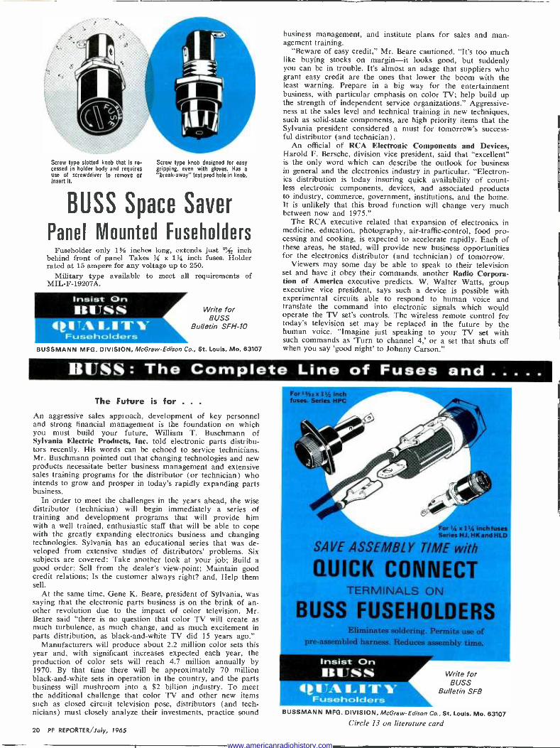
Screw type slotted knob that is re- cessed in holder body and requires use of screwdriver to remove or Insert it.
Screw type knob designed for easy gripping, even with gloves. Has a
"break -away" test prod hole in knob.
BUSS Space Saver
Panel Mounted Fussholders Fuseholder only 1% inches long, extends just P9/_ inch
behind front of panel Takes h x 1% inch fuses. Holder rated at 15 ampere for any voltage up to 250.
Military type available to meet all requirements of MIL -F -19207A.
Insist On IIITSS
.eTA..IT1- Fuseholders
Write for BUSS
Bulletin SFH-10
BUSSMANN MFG. DIVISION, McGraw -Edison Co., St. Louis, Mo. 63107
business management, and institute plans for sales and man- agement training.
"Beware of easy credit," Mr. Beare cautioned. "It's too much like buying stocks on margin-it looks good, but suddenly you can be in trouble. It's almost an adage that suppliers who grant easy credit are the ones that lower the boom with the least warning. Prepare in a big way for the entertainment business, with particular emphasis on color TV; help build up the strength of independent service organizations." Aggressive- ness at the sales level and technical training in new techniques, such as solid-state components, are high priority items that the Sylvania president considered a must for tomorrow's success- ful distributor (and technician).
An official of RCA Electronic Components and Devices, Harold F. Bersche, division vice president, said that "excellent" is the only word which can describe the outlook for business in general and the electronics industry in particular. "Electron- ics distribution is today insuring quick availability of count- less electronic components, devices, and associated products to industry, commerce, government, institutions, and the home. It is unlikely that this broad function will change very much between now and 1975."
The RCA executive related that expansion of electronics in medicine, education, photography, air -traffic -control, food pro- cessing and cooking, is expected to accelerate rapidly. Each of these areas, he stated, will provide new business opportunities for the electronics distributor (and technician) of tomorrow.
Viewers may some day be able to speak to their television set and have it obey their commands, another Radio Corpora- tion of America executive predicts. W. Walter Watts, group executive vice president, says such a device is possible with experimental circuits able to respond to human voice and translate the command into electronic signals which would operate the TV set's controls. The wireless remote control for today's television set may be replaced in the future by the human voice. "Imagine just speaking to your TV set with such commands as 'Turn to channel 4,' or a set that shuts off when you say 'good night' to Johnny Carson."
BUSS : The Complete Line of Fuses and The Future is for .. .
An aggressive sales approach, development of key personnel and strong financial management is the foundation on which you must build your future, William T. Buschmann of Sylvania Electric Products, Inc. told electronic parts distribu- tors recently. His words can be echoed to service technicians. Mr. Buschmann pointed out that changing technologies and new products necessitate better business management and extensive sales training programs for the distributor (or technician) who intends to grow and prosper in today's rapidly expanding parts business.
In order to meet the challenges in the years ahead, the wise distributor (technician) will begin immediately a series of training and development programs that will provide him with a well trained, enthusiastic staff that will be able to cope with the greatly expanding electronics business and changing technologies. Sylvania has an educational series that was de- veloped from extensive studies of distributors' problems. Six subjects are covered: Take another look at your job; Build a good order; Sell from the dealer's view -point; Maintain good credit relations; Is the customer always right? and, Help them sell.
At the same time, Gene K. Beare, president of Sylvania, was saying that the electronic parts business is on the brink of an- other revolution due to the impact of color television. Mr. Beare said "there is no question that color TV will create as much turbulence, as much change, and as much excitement in parts distribution, as black -and -white TV did 15 years ago."
Manufacturers will produce about 2.2 million color sets this year and, with significant increases expected each year, the production of color sets will reach 4.7 million annually by 1970. By that time there will be approximately 70 million black -and -white sets in operation in the country, and the parts business will mushroom into a $2 billion industry. To meet the additional challenge that color TV and other new items such as closed circuit television pose, distributors (and tech- nicians) must closely analyze their investments, practice sound
For 5nx1%Inch fuses. Series HPC
Br
or '/a x 114 inch fuses Series HJ, HK and HLD
SAVE ASSEMBLY TIME with
QUICK CONNECT TERMINALS ON
BUSS FUSEHOLDERS Eliminates soldering. Permits use of
pre -assembled harness. Reduces assembly time.
Insist On BUSS
QUA NAVY V FLisesholders
Write for BUSS
Bulletin SFB
BUSSMANN MFG. DIVISION, McGraw -Edison Co., St. Louis, Mo. 63107 Circle 13 on literature card
20 PF REPORTER/July, 1965
www.americanradiohistory.com

VISUAL INDICATING FUSE
BUSS SUB -MINIATURE FUSEHOLDER COMBINATION
-AlleFJSE ONLY .270 x .250 INCHES
GMW FUSE and IHWA FUSEHOLDER
For space -tight applications. Fuse has window for inspection of element. Fuse may be used with or without holder.
Fuse held tight in holder by beryllium copper con- tacts assuring low resistance.
Holder can be used with or without knob. Knob makes holder water-proof from front of panel.
Military type fuse FMO1 meets all requirements of MIL -F-23419. Military type holder FHN42W meets all military requirements of MIL -F -19207A.
Insist On 'MUSS
te TA 114 I TY Fuses and Fuseholders
BUSSMANN MFG. DIVISION, McGraw -Edison Co., St. Louis, Mo. 63107
Write for BUSS
Bulletin SFB
HELP!
Representing the American automobile industry, the Automo- bile Manufacturers Association, has developed a cooperative nationwide program by which motorists in distress can use two-way radio to obtain assistance in the event of an accident, mechanical problem, or other occurrence which incapacitates a vehicle or its driver on the highway. Called H.E.L.P. (for Highway Emergency Locating Plan), the plan is based on use of Citizens -band equipment.
Channel 9 is widely accepted throughout the country and monitored as the frequency for emergency aid to travelers. Ac- cordingly, channel 9 has been recommended as the channel to be used in the H.E.L.P. program whenever highway service or emergency requirements arise. Industry groups hope that later the FCC will assign exclusive radio channels to the H.E.L.P. program, to assure interference -free communications.
Motorists with H.E.L.P. equipment who need assistance, or who sight others who need help, will broadcast a plea on channel 9. This request for help will be answered by individ- uals and agencies who monitor this channel on a twenty -four- hour basis. Those monitoring include Citizens -band radio emergency volunteer teams, police agencies, road service sta- tions, and hospital emergency services. Need for medical help can also be relayed by telephone from police or others who are monitoring the channel.
Company Renamed
The name of the distribution subsidiary of Texas Instruments Incorporated has been changed from Engineering Supply Company (ESCO) to Texas Instruments Supply Company. Headquarters will continue to be in Dallas, with other offices and warehouses in Houston; Tulsa; Kansas City, Mo.; Canton, Mass.; and Union City, N. J. In recent months, international outlets have been established in Stuttgart, Germany; and London, England. Additional offices will be opened this year in Milan, Italy; and Paris, France.
Fuseholders of Unquestioned High Quality Scientists at RCA's Princeton laboratories have obtained a
patent for a syllable analyzer that takes spoken words apart and compresses them into electronic code. In its present form the analyzer can recognize about 200 syllables as spoken by several persons. It already is being used in an experimental phonetic typewriter that takes direct dictation.
Mr. Watts also predicted that color television sets of 10 to 20 years from now would be both larger and smaller than today's models. The bulb -like picture tube of today's television set should give way to a thin screen, 1" or 2" thick, operated possibly by integrated circuits. These screens could be large enough to cover a living room wall or small enough to fit in a pocket.
With predictions and advice like these also coming from others of the industry's top executives, technicians and dis- tributors everywhere should recognize that "the future is for" him who is prepared for the future. The future isn't for him who sits and waits.
New Phonos for Old
Even though that old phonograph gathering dust in basement, attic or garage hasn't issued a note in years, there's still a chance for it to provide musical pleasure. Benjamin Electronic Sound Corporation, Westbury, New York, has announced its beginning of a collection of old phonographs. The collection will eventually be made available to banks, schools, and li- braries as an educational service. G. Thalberg, national sales manager, said the company will give one of its Miracord record players in exchange for every ancient phonograph that is accepted. The company has not developed any "name list" of wanted phonographs, but a spokesman said that all inter- esting and unusual record players of ancient vintage will re- ceive consideration. No one should send an actual phono- graph to the company. The first step should be the mailing of a snapshot or rough sketch of the phonograph, along with its description.
T RO N PB -MINIATURE
IGTAIL FUSES
VISUAL INDICATING
BODY SIZE ONLY .145 x .300 INCHES
For use on miniaturized devices, or on gigantic space tight multi -circuit electronic devices.
Glass tube construction permits visual inspection of element.
Smallest fuses available with wide ampere range. Twenty-three ampere sizes from 1/100 thru 15 amps.
Hermetically sealed for potting without danger of sealing material affecting operation. Extremely high resistance to shock or vibration. Operate without exterior venting.
Insist On BUSS
QUALITY Fusas
Write for BUSS
Bulletin SFB
BUSSMANN MFG. DIVISION, McGraw -Edison Co., St. Louis, Mo. 63107
Circle 13 on literature card July, 1965/PF REPORTER 21
www.americanradiohistory.com

I, --mmos;.--- ...-.., Ji
_.
..:. ......... ,. ,.../Jr"
-.% ,r,
HOW DID WINE GARD
PUT FULL SIZE
POWER IN A '/z SIZE ALL -BAND
(UHF -VHF -FM) COLOR
ANTENNA?
A big disadvantage of most all -band (UHF, VHF, FM) antennas is that they are larger and heavier than necessary. This is because they are really VHF antennas with UHF antennas tacked on the front end. Chroma -Tel isn't. It's super -compact and the
....-
,, r""",......
WITH
WINEGAIID CHROMA -TEL
the new super -compact high
gain antenna designed specifically
for all -band UHF -VHF Color Reception and FM
first integrated antenna designed specifically for all -band UHF -VHF color operation.
How did we reduce the size so drastically without sacrificing performance?
Two ways. First with our new Chroma -Lens
www.americanradiohistory.com

Director System. With this unique system, we are, for the first time, able to intermix both VHF and UHF directors on the same linear plane without any sacrifice of performance.
Second, with Impedance Correlators. These are the special phasing wires that automatically step up the impedance of Chroma -Tel's 72 ohm driven elements to 300 ohms. The correlators make sure each element has an accurate 300 ohm impedance at its given frequency. No other antennas with mul- tiple driven elements have this! They also allow us to place the elements only 53/4" apart instead of 10" to 14" apart as on other all -band antennas, reducing antenna length by one-half.
With the new Winegard Chroma -Tel antenna, we have eliminated half the bulk, half the wind loading, half the storage space, half the truck space, and half the weight ... yet still have the best work- ing, easiest installing UHF -VHF - FM antenna ever developed!
You give your customers a neater installation that performs as well or better than any other all -band antenna on the market ... and at a much lower price.
Compare Performance. You can't find an all -channel UHF -VHF -FM antenna that will give you better results than Chroma -Tel. Look at the polar patterns. There are no side lobes with Chroma -Tel because the elements are straight .. .
unlike V'd elements that offer an element surface sideways to the signal, Chroma -Tel's straight ele-
Exclusive Winegard Impedance Correla - tors insure 300 ohm impedance on each element
Compare Size and Price. We've illustrated the super -compact Chroma -Tel CT -80 and a com- parable V type antenna. Note the difference in size, price and weight for equal or better per- formance. Because it's even much smaller than ordinary VHF antennas of comparable perform- ance, it is perfect for attic installations, too!
140.
60.
Winegard Chroma -Tel V type (Approximate Figures) Boom Length: 60" 140" Total Weight: 5 lb., 1 oz. 10 lb., 3 oz.
Carton Size: .97 cu. ft. (less than 1) 5.8 cu. ft. Number of 17 12
Elements: List Price: $27.50 $50.00
ments will not pick up ghosts from sides or back. Chroma -Tel's front -to -side ratio is practically in- finite-Chroma-Tel's exceptional front -to -back ratio is up to 30 db.
Compare Construction. The Chroma -Tel is Winegard quality throughout ... from its sales -making com- pact 4 -color box, to its weather resistant Gold Vinyl- ized Finish, to its first quality snap -lock hardware.
For complete information on the exciting new Winegard Chroma -Tel All -Band Antenna, ask your distributor or write .'
for Fact -Finder #242 today.
Typical V Type Antenna Polar Pattern
So compact it fits in the back seat of a car
All Chroma -Tels include Winegard's model CS -283 UHF -VHF signal splitter. Splitter hangs conveniently behind TV
set. Separates UHF and VHF signals coming from antenna to the two sets of terminals on your set. It's yours FREE
when you buy Chroma -Tel.
Model CT -90 $37.50
Model CT -SO $27.50 Model CT -40 $17.50
mnegand Co. Antenna Systems
3009H Kirkwood Burlington, Iowa
Circle 14 on literature card
www.americanradiohistory.com

PHASING Multiple -Antenna
SYSTEMS Improved gain isn't the only consideration.
by Jack
Most technicians think of stack- ing antennas only in terms of in- creasing signal strength. Actually, there are many other excellent rea- sons for combining two or more antennas, and there are more ways of doing it than just putting them in a vertical row on a mast. By stacking antennas, you can: 1. Increase signal strengths, thus
improving signal-to-noise ratios 2. Reject ghosts 3. Reject man-made interference 4. Reduce fading from distant sta-
tions 5. Reduce airplane flutter 6. Reduce adjacent -channel inter-
ference 7. Reduce co -channel interference
These benefits can be achieved because of one basic principle: The radiation pattern of an array of stacked antennas is different from the pattern of a single antenna. In order to use this principle, you must understand it fully.
Single -Antenna Patterns
In order to get an insight into what an antenna pattern really is, it's easiest to start with the dipole pattern shown in Fig. 1. You can
270°
1so°
112 WAVE
DIPOLE
90°
Fig. 1. Sensitivity of simple 4 -wave dipole plotted for horizontal plane.
Leever
think of this pattern best in terms of signal reception. If you were to take a transmitter of fixed power and move it in a circular path around the antenna, the received signal am- plitude would vary with the posi- tion of the transmitter. The dipole would pick up maximum signal when the transmitter was at 0° and 180°. It would pick up almost no signal when the transmitter was at 90° and 270°. The curve indicates relative pickup at al lother angles.
So far, it has been assumed that the transmitter was moving around the antenna on a horizontal plane. However, the antenna can also re- ceive signals from directly above and below it, or any angle in be- tween.
The diagram shown in Fig. 1, therefore, is actually just a cross- section of the complete pattern. The total pattern is doughnut-shaped- technically, it's a toroid with the dipole as its axis.
Most commercial antennas are designed in an attempt to elongate the forward lobe of the pattern (in the 0° direction) and attenu- ate, or reduce, the rear lobe (in the 180° direction) . Fig. 2 shows a typical yagi pattern as plotted on a special instrument for testing an- tennas.
The patterns shown so far were developed in a plane parallel to the earth's surface. Since television an- tennas are horizontally polarized, this is the E plane - the electri- cal field pattern. At right angles to the E plane is the H plane, which contains the magnetic field com- ponent of the electromagnetic wave. The signal power received by an antenna or antenna array is depend- ent on both the magnetic and the electrical fields.
Stacked -Antenna Patterns
Fig. 3 compares the E -plane and H -plane reception patterns of a typical yagi with those of various stacked arrangements of antennas of the same type. Notice that verti- cal stacking produces narrowing of the forward lobe only in the mag- netic field. The E -plane pattern re- mains the same. Conversely, hori- zontal stacking provides gain only in the electric field. If you do both (stack two antennas high and two antennas wide), you get gain in both fields. This is called a quad stack or a "2 x 2 array."
Useing Nulls
Stacking antennas can produce increased gain in the forward direc- tion, but look closely at Fig. 3 and you'll see that some very sharp nulls are also created. It is by judic- ious use of these nulls that items 2 through 7 on the list of effects of stacking can be produced.
Fig. 4 illustrates two dipoles stacked side by side, with a space of one wavelength between centers. In Fig. 4A, the transmitter is in the 0° direction. In other words, the signals are arriving broadside to the two antennas. Since both dipoles "see" the same wavefront at the same time, the currents developed by the two antennas are in phase. Provided the phasing harness does not change this situation, the two signals will add at the mixing point and deliver twice the power received by either dipole-a 3 -db signal gain. Fig. 4B shows the same two phased antennas receiving signals from a transmitter located 30° from center. Notice that while dipole D1 is ener- gized by wavefront W1, dipole D2 is energized by the wavefront im- mediately behind it (W2), which is 1/2 wavelength, or 180°, out of phase with W 1. Each alternate wavefront induces currents of op- posite polarity; the currents induced in D1 and D2 are therefore equal and opposite. Instead of adding, they cancel each other at the mix- ing point.
Fig. 4C illustrates the reception pattern of this pair of horizontally stacked dipoles. In addition to the null at 30°, others are produced at 150°, 210°, and 330°. As can be seen in Fig. 4C, the reception pat- tern is similar to that of a single di- pole except for the deep "dimples"
24 PF REPORTER/July, 1965
www.americanradiohistory.com

210° 200 190 190° no 150 150`
ISD 190 1l0 190 200 2W' 1 e, .. ...
w .',, ,,... eta.a; ',,' ,,/,,,.. ' ºó
230 .
230° 130 5°'/'., eiI! gi, z20:
1
.
,,,,,,,```` o',/',,t, ''' , `, I 250
- / ','' 1100° I'; 290°250 ___` . _ _`'``` ,-.- / ' Ì_- 0 2T0 2T0 -.iii! WW Ì% ÌD WII // ,W e -°
80°
ä , ,/ ,',i',````;,,, , ,`" 1, ,,, / '
I
zo°
G° iiIíi 3-: ...,,,,,,,,',,t'', 310 eia0 320 ....''' .... 320° ...... 00
.. . 330 330 350° °
10° 20° 30 30° 20° Ö° 350° 360 330°
Fig. 2. Yagi antenna pattern plotted in
caused by the cancelling effect due to horizontal spacing.
Do the nulls always appear at 30°? Only if the horizontal spacing between the dipoles is precisely one wavelength at the frequency being received. You can change the angle of the nulls simply by changing the spacing.
When to Use Horizontal Stacks
There's not much point in using horizontal stacks just to increase signal levels; the same gain can be obtained from a vertical stack with considerably less mechanical trouble and expense. But those lovely nulls resulting from horizontal stacking can help to eliminate ghosts, adja- cent -channel interference, cochan- nel interference, and sometimes even interference from man-made noise.
The most common use for hori- zontal stacking is to solve difficult ghost problems. A ghost is a signal bounced from some obstruction, but it also can be considered as a signal originating from another transmitter sending out the same programs on the same frequency. The only differ- ences between the original signal and the ghost are that they arrive from different directions and the ghost arrives a little later than the direct signal.
horizontal plane.
ANTENNA ARRAY
SINGLE YAGI
VERTICALLY STACKED VAGIS
///1///1 ///1///
HORIZONTALLY STACKED
VAGIS
"QUAD" STACK
PATTERNS
E PLANE
\J
o) H PLANE
0E )
Fig. 3. E- and H -plane patterns of single and stacked yagis.
To eliminate the ghost, you must, in some way, eliminate the signal from the ghost transmitter. The usual method, which should be tried first, is to use a high -gain antenna. Try to orient a null of the antenna pattern toward the ghost source while still receiving enough usable signal from the prime source. If this approach fails, the horizontal stack must then be used.
The exact angle of the ghost sig- nal in relation to the prime signal source rarely is known. Therefore, a practical cut -and -try approach to finding the correct antenna spacing must be made.
Connecting the Antennas
Another point to be kept in mind is that 300 -ohm twin -lead, especial- ly when run horizontally, tends to act as an antenna itself. Therefore, coaxial cable should be used to con- nect the two antennas.
Fig. 5 shows how a pair of an- tennas should be stacked horizontal- ly. Matching transformers, mounted close to the antenna terminals, are used to match the 300 -ohm an- tennas to 75 -ohm coaxial cable. The antennas must have identical char- acteristics; this usually means they should be the same make and mod- el. A convenient length of coaxial cable is then taken from each matching transformer to a hybrid -
type splitter-mixer. There are three very critical points in preparing this harness I. Lead lengths between each an-
tenna and the splitter-mixer
WAVEFRONT FROM
ThIE TRANSMITTER
W3+++++ W' -
-f-+++-
'a+ ++ -
TO RECEIVER
(A) Reception at 0° {yj WAVEFRONT FROM
THE TRANSMI TER
n _
)4.
TO RECEIVER
(B) Reception at 30° 33o°
2l0° L50°
(C) 360° reception pattern
Fig. 4 (Reception patterns of i -wave dipoles spaced one wavelength apart.
July, 1965/PF REPORTER 25
www.americanradiohistory.com

A
HYBRID SPLITTER - MIXER
TO RECEIVER
TWIN LEAD
MATCHING TRANSFORMER
COAXIAL CABLE, 75 OHMS
(RA -59M OR EQUIVALENT TYPE)
Fig. 5. Proper method of connecting horizontally stacked yagis is shown.
must be identical. Use the same length of twin -lead and the same length of coax for each antenna.
2. The matching transformers must be phased properly with the an- tennas. Connect the left-hand terminal of the transformer to the left-hand terminal of the an- tenna. If this is not done, you will have out -of -phase currents at the mixing point.
3. Use a hybrid -type splitter-mixer. Aside from the fact that it must
be perfectly symmetrical, this har- ness is not critical. It can be used to combine any VHF antennas and to receive any VHF frequency. It can also be used for UHF, provided equivalent UHF antennas, matching transformers, and hybrid splitter- mixers are used.
Once the harness is set up, the output of the splitter-mixer is con- nected through a matching trans- former to the TV receiver. You are now ready to determine the correct spacing for the two antennas.
Adjusting the Antennas
Keep the two antennas parallel and pointed in the same direction- toward the prime signal source. Slowly move one antenna away from the other. At some point, you will see a sudden, sharp reduction in the intensity of the ghost. Mount the antenna at this point; then move the antenna up and down for maxi- mum ghost reduction.
What you have done is to move the antennas apart until the null fell on the angle from which the ghost was being received. Then, you moved one of the antennas up and down until each antenna was re- ceiving equal ghost signal power. The second action helps because only equal and opposite voltages cancel.
This useful technique can also be used to eliminate adjacent -channel interference (for example, channel 3 interferes with channel 4) and co - channel interference (an unwanted
channel 3 interferes with a desired channel 3) . If man-made interfer- ence comes from a specific location (as opposed to a diffuse source such as a power line), a properly spaced horizontal stack can be used to minimize it.
The horizontal array can be used broadband, but the nulls will differ in angle for each channel. Still, for- ward gain will be achieved on all channels; it is impossible to make a null at 0° or 180° with this type of array.
Vertical Stacking
Vertical stacks are most com- monly used to increase gain. How- ever, they are also useful in mini- mizing signal fading. To understand how, you must understand the causes of fading.
In the first place, fringe locations are always "over the hill." In other words, there is no line -of -sight re- ception. The source of trouble is the fact that signals arrive over the hor- izon by more than one path. For example, they may arrive by diffrac- tion (bending) over an obstruction or because of refraction or reflection by atmospheric layers. Notice that only one of these sources of signal bending-diffraction by an obstruc- tion-is stable. The others vary as the layers themselves move. Because of this behavior, the different signals which arrive at the receiving anten- na will have different path lengths.
In Fig. 6, two reception paths are shown; one is diffracted over a mountain top, and the other is re- flected from an atmospheric inver- sion. The second path is the longer one. If it is longer by any odd num-
ber of half -wavelengths, the signal arriving by this path is out of phase with the diffracted wave, and the two will cancel. If the second path is longer by any number of whole wavelengths, the two signals will ar- rive in phase, and they will add to give a greater signal than either could provide alone. But the re- flected wave is from an inversion, which is constantly changing posi- tion. Hence, the path length is con- stantly changing; and, as it changes, the two signals go in or out of phase to produce a varying signal intensity.
These signal variations are short- term fades. In actual practice, the effect is highly complex, since there may be four or more different sig- nal paths over the horizon. While this may seem like an almost hope- less situation, it is not. Here's how it can be handled.
Signal Diversity
Consider a tall mast, with one an- tenna on top of the mast and anoth- er about halfway down. Imagine a line drawn from each antenna to the horizon; the lines represent the path of the diffracted signal. Both paths ("A" and "B" in Fig. 6) have practically the same length. Now consider paths "E" and "F" (from the atmospheric inversion). "E" is longer than "F" by the amount "D." Assuming that signal "F" arrives at the top antenna in phase with signal "A," then signal "E" must arrive with some different phase relation- ship with signal "B." Thus, the top antenna can be producing strong signals while the lower is producing almost none. The situation can read- ily reverse itself as the atmospheric
Please turn to page 50
ATMOSPHERIC INVERSION
F
E
A
B
- - HORIZON
GROUND LEVEL
SIGNAL -PATHS FROM TRANSMITTER
Fig. 6. Multiple signal paths are involved in reception over the horizon.
26 PF REPORTER/July, 1965
www.americanradiohistory.com

overcoming
In the middle of a long, hot sum- mer, the effects of winter and spring winds on TV, CB, and amateur an- tennas probably seem a long way off. The fact is, however, that right now is the best possible time to give serious consideration to these prob- lems so that allowance can be made for them during the erection of an- tennas and antenna systems. Each part of every installation is affected by wind presence and ice loading, but many technicians are unaware of these effects; some know about them but choose to ignore what they know. Either situation can cause serious difficulty, particularly in the case of property damage or personal injury resulting from an improperly installed system. The number of
!f//NO LOAD EFFECTS
Techniques for avoiding blowdown.
by Allen B. Smith
fallen antennas in most areas, fol- lowing wind storms of even moder- ate intensity, bears testimony to the lack of planning in many installa- tions.
Three Factors to Consider
Before you can understand what contributes to the strength or weak- ness of an antenna system, you must have some basic data with which to work. First of all, you should know how much wind pressure can be ex- pected to work toward defeating your best -laid plans. Secondly, the resistance to the wind presented by the antenna, mast, tower, and guys must be determined so that the total force exerted on the system may be calculated. Thirdly, you must de -
Fig. 1. Coastal areas receive average winds of higher velocity than rest of U.S.
termine whether or not the equip- ment used in the system reasonably can be expected to carry the load.
Determining Wind Pressure
To provide standard references for the effects of wind on antennas, the Electronic Industry Association (EIA) has compiled data on maxi- mum wind velocities recorded by the U. S. Weather Bureau since 1932. These figures have been eval- uated and averaged out so that one can determine approximately what maximum wind loads will appear on systems installed in various parts of the country.
Wind pressure can be calculated from the formula PK(Va) 2, where P is the pressure in lbs/sq ft, K is
a constant coefficient which de- pends on the shape of the elements used in constructing the antenna (.0025 for cylindrical elements and .0042 for flat -faced elements), and Va is the absolute velocity of the wind recorded in a given area.
Weather Bureau records indicate that maximum velocities during nonhurricane conditions range from 62 mph in Washington, D.C. to 92 mph in Minneapolis, Minnesota. All other areas in the United States, except for the coastal areas subject to hurricane windstorms, fall within this range. Since gusting occurs at levels which exceed the measurable peak velocities by approximately 30%, the EIA has adopted the fig- ure of 110 mph as the maximum velocity expected over most of the U.S. Applying the estimated maxi- mum Va to the formula for deter -
July, 1965/PF REPORTER 27
www.americanradiohistory.com

mining wind pressure on antennas employing cylindrical elements, the EIA standard figure is determined:
P=.0025x1102 .0025 x 12100
= 30.25 lbs/sq ft Rounded off for convenience, the figure of 30 lbs/sq ft can be relied upon for West Coast and inland areas.
Along the Gulf and East Coasts, there are rather extensive areas which are subjected to frequent buf- feting by winds of hurricane veloc- ity. Fig. 1 shows these areas in gen- eral terms. The cross -hatched areas represent those in which winds of 100 mph have been recorded with some regularity. Once again apply- ing the formula for wind pressure, we derive a figure for this wind belt of 42.25 lbs/sq ft (with allowance for 30% increase in velocity for gusting, Va = 130 mph). The areas shown in black denote those in which winds in excess of 115 mph are regularly recorded. Using a fig- ure of 150 mph to allow for gusting, we find that expected wind pressures have risen to 56.25 lbs/sq ft. Since the total wind pressure increases in proportion to the square of the wind velocity, it can be seen clear- ly that relatively small increases in wind speed greatly increase the total pressure.
Isolated locations across the country have recorded extremely high winds during some storms, and this unpredictability can give a tech- nician real headaches. As an ex- ample of the way wind pressures can build up alarmingly, wind ve- locities of 188 mph were recorded
on Mt. Washington, New Hamp- shire. With the gusting factor added, Va becomes 244.4 mph, and the wind -pressure figure reaches a dis- astrous 149 lbs/sq ft. Working with the average recorded winds, how- ever, will provide a good starting point.
The information provided by the map showing the high -wind belts is probably a little too general for reliable use in many localities where geographical and atmospheric con- ditions combine to create a non - average wind pattern. Therefore, it always would be a good idea to ob- tain local wind information direct- ly from the nearest Weather Bureau and use those figures for calculat- ing wind pressures which will apply to a specific area. Remember that most figures received from the Bu- reau will be absolute velocities which do not include the 30% fac- tor for gusting. Don't forget to add that into your calculation.
System Wind Resistance
Now that you can determine a specific figure which represents the wind pressure applied to an an- tenna system in most any locale, you must come up with a second figure -the projection area of the an- tenna and its major structural com- ponents.
Fig. 2 illustrates the method used to calculate the actual projected area of a multielement yagi antenna typical of many fringe -area instal- lations. The projected area is de- termined by measuring the length and diameter of each structural com- ponent of the antenna, multiplying
LIGHT RAYS
3/4"
PROJECTED AREA = SUM OF TWO-DIMENSIONAL PROJECTION OF EACH SEPARATE ELEMENT.
3/4"
the two dimensions to obtain the projected area of each element (usually solved for sq in.), adding the areas of all antenna elements to- gether, and then dividing by 144 to determine the final projected area in sq ft.
As an example, some multiele- ment low -band yagis have booms of 1.5" diameter which are more than 10' long. Such a boom would have a projected area of 180 sq in. (120" x 1.5"), and if the boom carries 12 elements .75" in diameter which av- erage 40" in length, then each ele- ment has a projected area of 30 sq in. (40" x .75"). The total projected area for this hypothetical low -band antenna is 180 + (12 x 30) - 180 + 360 - 540 sq in. To get the equivalent figure in sq ft, divide 540 by 144; the result is 3.75 sq ft. Ad- mittedly, this is a pretty large and unwieldly antenna, but it is typical of fringe -area low -band yagis. Add- ing a rotator to the system brings the total projected area up to 4 sq ft.
Recalling now that the average wind -pressure figure for most of the U.S. is 30 lbs/sq ft, a little simple arithmetic reveals that the total force applied to the antenna is 30 x 4, or 120 lbs. Now that you have a couple of firmly established fig- ures, it is a little easier to see what kind of previously unsuspected forces you have to deal with in put- ting up an antenna. There is still another factor, however, which really throws a monkey wrench into the picture. The new factor is called the "bending moment" and relates to the situation illustrated in Fig. 3.
UNSUPPORTED 3 FT. LENGTH
PROJECTED AREA OF
ANTENNA - 4 SQ. FT.
WIND PRESSURE - 30 LBS./SQ. FT.
WINDLOADING = 120 LBS.
BENDING MOMENT
- 360 LB. -FT.
Fig. 2. Projected area of antenna is equivalent to shadow
28 PF REPORTER/July, 1965
Fig. 3. Bending moment equals windload X free length.
www.americanradiohistory.com

The term is simply another way of
referring to the effect of leverage upon the supporting mast.
As shown in the illustration, if the mast is guyed at a point l' below the boom, the bending moment is numerically equal to the total force applied to the antenna structure. If the guying point is 2' below the boom, however, the bending mo- ment is doubled, and if the guying point is 3' below the boom, the mo- ment is tripled. The bending mo- ment is expressed as a torque in lb -ft.
To provide a vivid example of what you must contend with, as- sume that you install the hypotheti- cal antenna (which has a projected area of 4 sq ft) on a 1" mast and guy the mast 3' from the boom. If the structure is exposed to a 110 - mph gust of wind (EIA standard 30 lbs/sq ft wind pressure), you have a situation equivalent to tak- ing that poor little 1" mast, tying it to the workbench with 3' sticking out over the edge, and then hooking a 120 -lb weight onto the unsup- ported end (4 sq ft projected area x 30 lbs/sq ft wind pressure = 120 lbs) . The bending moment exerted on the mast at the guying point is 360 lb -ft. No imagination is re- quired to see that the whole array will make like a pretzel. If you think you're in deep trouble at this point, wait until the cold winter winds blow and ice builds up 1/4" thick.
Staying with the hypothetical low - band yagi which has a projected area of 4 sq ft with rotor, a few calculations will show that the 1/4" of ice will increase the projected area considerably. The main boom which had a diameter of 1.5" un- coated, has increased by .5" so that its projected area reaches a figure of 240 sq in. The .75" diameter elements have grown to 1.25" in diameter, and the projected area rises to 50 sq in per element. In- stead of the original ice -free total of 540 sq in, we now have a projected area of 840 sq in, or 5.83 sq ft. Adding a rotator increases that fig- ure to 6.08 sq ft, slightly more than a 50% increase in total area.
Under the same mounting condi- tions described above (a 1" mast guyed 3' from the boom), a 110 - mph gust that creates a wind pres- sure of 30 lbs/sq ft will exert a
Fig. 4. Amateur multiband antenna has projected area of more than 10 sq. ft.
bending moment of 550 lb -ft. Fan- tastic? You're right, it is; and these factors of wind pressure and bend- ing moment are mighty easy to overlook, too.
It may seem that using a large low -band antenna to illustrate the problem exaggerates wind -pressure effects, but a structure of that type actually represents (with its pro- jected area of 4 sq ft) a median surface area. Understandably, most high -band VHF and all UHF and FM antennas will present far less re- sistance to wind pressure, but vir- tually all CB and amateur -band an- tennas will exceed 4 sq ft by a wide margin. An average figure for CB arrays would be on the order of 7.5 sq ft, and a typical amateur in- stallation would range from around 5 sq ft for fairly simple arrays to as much as 16 sq ft in the case of multiband arrays. The antenna shown in Fig. 4, for example, has a projected area very close to 10 sq ft. Whenever faced by an unfamiliar situation or an especially complex installation, you would do well to make a few preliminary calcula- tions such as have been described here-it's good insurance.
Selecting Materials and Equipment
Many manufacturers have help- ful information available for the asking and will gladly respond to specific inquiries regarding actual projected area of their antennas, strength of masts, and correct guy- ing methods and insulator selection. Manufacturers of other antenna equipment also can be a very good source of data. Rotator -assembly in- formation of comprehensive depth for evaluating mechanical strength
and installation techniques, for ex- ample, is available from Alliance Mfg. Co., Cornell-Dubilier, and Channel -Master. Don't overlook EIA recommendations on antenna erection methods, either. If antenna - system design and/or installation is
one of your strong fields, you likely will have gathered much of this in- formation already. If it has seemed to fall in the category of "so what?" material until now, perhaps you'll find a little more practical use for it. Select your equipment carefully, and if you have specific questions regarding the suitability of any com- ponent, determine what information you need to know to complete a series of calculations and ask the manufacturer. If you don't receive convincing data from that approach, it is a whole lot less expensive to run a few static tests in your shop using sand -filled buckets for simu- lating loads than it is to face a law- suit.
Conclusion While many antennas can be
erected with little thought or con- sideration, that sort of hasty instal- lation can give you considerable time to repent at your leisure. The next time your town is struck by damaging winds or ice storms, don't be among those who have to "make - good" several inadequate antenna jobs. Remember, too, the least pos- sible damage that can result from the loss of an antenna is lost custo- mers, and the worst is frightful to consider. Don't be responsible for personal injury accidents, property damage, and the resulting expensive lawsuits. They might cost you your business.
July, 1965/PF REPORTER 29
www.americanradiohistory.com

Maintenance of ANTENNAS & TOWERS
Picture yourself in this situation: The phone rings; a somewhat per- turbed housewife announces, "My TV is action strangely; sometimes the voice and picture disappear for a few minutes and then are normal again. At times the ghosting is bad,
Timely suggestion: Get these
things done before winter!
and it also comes and goes. Can you come out and take a look at it?" Sure you can; that's your business.
As you approach the customer's house, you make a quick visual check of the antenna and lead-in. It seems okay. Inside the house,
BENTON CITY RADIO/TV CENTER Benton City, Wis.
ANTENNA SYSTEM INSPECTION REPORT Date
Technician for
Items Satisfactory Hazardous Loose Corroded Broken Rust.
ANTENNA
Elements
Electrical connections
_ / (/ /
j
LEAD-IN CABLE
Insulation
Strain relief at terminals
7 Y
SUPPORT MAST
Section joints
Mounting base V -- Bolts and nuts
Guy wires
Guy wire insulators
TOWER STRUCTURE
Section joints
Bolts and nuts 6/
Crank -down mechanism
/
Tilt -over hinging
Hoist cable `/ Safety catch
Guy wires
Guy wire insulators
Fig. 1. Detailed report is essential to both the inspector and the customer.
by Howard S. Pyle
your routine checks don't reveal the source of trouble, so you decide to take the set to the shop.
On the bench the set works per- fectly. You let it play for a half hour, and still there is no sign of a malfunction of any kind. Somewhat reluctantly, you return the set to the customer, realizing that she isn't going to be happy about paying "just for the side." You replace the set in the living room, connect the antenna and power cord, turn it on, warm it up, and w -h -o -o -p -s ... a terrible picture with snow flurries and ghostly visitations! The speaker crackles, and the voice breaks at frequent intervals. There's one for the book.
You don't panic, but you are puzzled. It works in the shop but goes wacky in the home; what could there be at the house that would so upset the performance? When you made your initial call, you took a casual glance at the antenna, and it looked okay. But is it? The anten- na, lead-in, and AC power are the only external items in the instal- lation. Just on a chance, you change the plug to another wall outlet on a different circuit. No go; same troubles persist.
You have a pair of rabbit ears in the truck, so you give them a try, disconnecting the normal antenna, of course. You turn on the set, let it warm up, and then let it play awhile. Ten minutes later the voice and music are still perfect, and the gleaming eye shows no ghosts, no snow, just a very acceptable picture.
This has pretty much pinpointed the antenna or the lead-in as being defective. From the ground, a visual inspection of the lead-in shows it to be in good condition, at least from
30 PF REPORTER/July, 1965
www.americanradiohistory.com

the set to the rain gutter over which the twin -lead disappears. The trou- ble must be either the lead-in con- nection at the antenna, a chafed spot in the twin -lead not visible from the ground, or the antenna itself.
You remove the ladder from the truck, and up on the roof you go. Your inspection discloses that the wind has broken one of the lead-in conductors. Furthermore, the porce- lain eye of one of the stand-off in- sulators on the roof has cracked and fallen from the screw -eye, and the lashing of the recent wind has completed abrasion of the twin -lead against the rusted iron screw -eye to the point where both conductors are bare and scraping against the eye. Beyond a doubt this accounts for the trouble in the receiver.
Time and Money Savers
Trouble calls such as the one de- scribed here are not uncommon; however, locating and clearing such faulty performance is often frustrat- ing. In the average TV installation with a roof -top antenna, the custo- mer promptly forgets, after the in- itial installation, what's on the roof, never giving it a thought when trou- ble develops. Immediately he jumps to conclusions; "There is something wrong with the TV-call the service shop." And unfortunately, many shop owners and technicians have fallen into a similar habit. If a quick visual inspection from the ground shows the antenna and its mast or tower in a reasonably upright posi- tion, it is assumed that there is nothing wrong there; again, "it must be the set," and off to the shop it goes. This costs the customer an unnecessary service charge and costs you time which might have been de- voted to more profitable sales or service calls. A little forethought and planning will reduce both of these elements substantially.
You've done enough TV service to be able to recognize the more common causes of faulty perform- ance when you see the symptoms. Most of these indicates a check of tubes and a visual inspection in the home without chassis removal. Many times, this is sufficient; re placement of one or two defective tubes and perhaps tightening a term- inal here and there will clear the
trouble, save considerable time, and make the customer relatively happy with a nominal charge. However, if
you don't locate the trouble spot quickly through your routine checks, give more than a passing thought to the antenna system be- fore you jerk the chassis or lug the set to the shop. Make it a point to carry a pair of rabbit ears with you in the truck; they will give you a quick check on possible antenna faults. A hundred feet or so of twin - lead also takes little space and may save you an extra trip to the shop if you find a lead-in so deteriorated that it requires replacement. Carry a few extra screw -eye standoff in- sulators as well, to replace any broken ones you may find.
Spotting Antenna and Tower Failures
As for the antenna itself, don't be satisfied just to look for a broken lead-in connection or chafing of the twin -lead insulation. Unlike the TV
set, which is protected in the home to the same extent as a piano or organ, the antenna takes an un- merciful beating, particularly in
areas which are subject to long, cold,hard winters. It is exposed to the ravages of nature the year 'round, day and night. Wind -whip causes vibration of the elements; vibration eventually causes break- age, particularly at joints of anten- nas whose active elements are crimped or brazed together in sec- tions. Such cracks, not at all discern- ible from ground level, can wreak havoc with picture reproduction and cause audio scratchiness. Once you're on a roof or up a tower, make your antenna inspection thorough. The inspection report shown in Fig. 1 lists many of the things to look for. The arrows in Fig. 2 shows the points that should be inspected carefully for different types of installations. Some anten- nas may be repairable if the prob- lem is a simple matter of bent or
Please turn to page 54
(A) Typical TV antenna
i" 41
(B) Sectional telescoping mast
(C) Stub type roof -mount mast
(D) Steel lattice -type tower
Fig. 2. Beware of these potential antenna trouble spots when making inspection.
July, 7965/PF REPORTER 31
www.americanradiohistory.com

for 1965
The accompanying chart of manufacturers and types is provided as a guide in antenna shopping. As a further aid, a brief description of each type is given also. Many different models are available from each manufacturer; you can obtain specific details from your distributor.
For very long-distance reception, the collinear array delivers a snow - reducing signal.
The many parasitic elements of the yagi antenna provide for high gain and sharp directivity.
The log -periodic antenna design provides high efficiency and even response over a wide range of fre- quencies.
The bow -tie antenna provides high gain and broad response in a light- weight and compact unit.
32 PF REPORTER/ July, 1965
www.americanradiohistory.com

A lightweight, high -gain, and high- ly directive type is the planar -heli- cal antenna (two types are shown).
The parabolic antenna provides very high gain with a high front - to -back ratio. The screen behind the driven elements is designed to reflect and focus the signal upon the driven element.
Two screens meet to make a corner and reflect the signal toward a wideband driven element to form the corner -reflector antenna.
Antenna Types
Manufacturer
V
o ç o o.
X
"
d O
3 o
aa
X
.
o >-
0 u a,
á o'. V.
ç o V
X
V Iii o
41
o ..4
º = L
c a
Q.
V
GI
c V
-o N
i c a d
Admiral ANDI X X Antennacraft X X Blonder -Tongue X Channel Master X X X X X Finney X X X X X Gavin X X GC X X X Hi -Lo X X X IE X X Jerrold -Taco X X X JFD X X X X X RMS X X S&A X X Trio X Winegard X X X X Zenith X X
July, 1965/PF REPORTER 33
www.americanradiohistory.com

finding and curing
RF Interference New ideas for an old problem.
by Thomas R. Haskett
Handling RF interference prob- lems can be quite simple if you use the system concept. Although the receiver is theoretically a closed unit or box which admits only the desired signal, it actually is part of a reception system which includes the building, surroundings, antenna, ground connection, and (unless it's a battery set) the power line. Should you take the receiver back to the shop, you may "cure" the trouble only to find it still exists at the customer's home when you return.
Receiver Substitution
Assume you are called to a cus- tomer's home on an interference complaint. First, eliminate the re- ceiver as the source. If possible when making such a call, take along an AC -powered set and a line filter, such as Cornell-Dubilier's Quietone or Sprague's Filterol. If the trouble disappears when your set (without the filter) is plugged into the AC receptacle, the customer's set may be generating its own interference. In TV, this often shows up as wig- gly vertical lines along the left side of the raster; these are called Bark - hausen oscillations, or snivets. The condition is a result of radiation from the horizontal -output tube be- ing picked up by the tuner. It usual- ly can be cured by attaching a small permanent magnet tc the envelope of the horizontal -output tube.
If the preceding test fails, try your
Fig. 1. Shot interferenre in television.
11141.1111,10$
+i! (ÌiiilÌ¡i',ii
receiver with a line filter in the AC feed. You will probably have to find a good ground for the filter to be ef- fective, so be sure to take a few clip leads along.
If the power line cannot be blamed for the interference, it's probably coming through the an- tenna. You could try shorting the antenna leads to see if the interfer- ence disappears, although this isn't conclusive. The undesired signal could be beating with the desired signal to cause a disturbance, and shorting the antenna terminals would kill the desired signal and, consequently, the beat. Further- more, don't forget that sometimes a poorly shielded receiver will pick up strong RF interference directly via chassis wiring, not from the antenna or power -line leads.
Types of Interference
There are two basic types of in- terference: random or transient in- terference that is usually caused by electrical devices and covers a broad band of frequencies, and fixed inter- ference which is produced by elec- tronic devices and occurs at a spe- cific frequency. Transients, rich in harmonics, are created by current impulses in motors, auto ignitions, and neon and fluorescent lights. These transients are often carried by the power line to produce video interference called "shots," "hits," or "birdies" (Fig. 1). A battery portable often can be used to follow such interference to its source.
Fig. 2 shows one such source-a furnace containing a blower motor with dirty, misadjusted brushes. After the commutator was cleaned and the brushes readjusted, the in- terference disappeared. When you find something like this, also check the motor ground.
In radio, electrical noise usually sounds like clicks, pops, and buzzes. Fluorescent lights are the usual
cause of buzz. Turn them off to see if the noise disappears. If so, try a .01-mfd, 600 -volt capacitor across the AC line inside the lamp housing. Make sure the metal lamp frame is grounded; if the capacitor doesn't work, try a line filter. In sevére cases, check the ballast; if it's a 15% low -power -factor type, replace it with a 90% high -power -factor type.
Fixed interference is generated by transmitters in all services-broad- cast, amateur, CB, police, taxi, etc. -and by receiver local and deflec- tion oscillators. In each case the in- terference is amplified and radiated in such a way as to mix with the de- sired signal. Fixed interference can be transmitted by way of the power line; the effectiveness of a good line filter and a good ground with the shortest, largest wire connected di- rectly to earth cannot be over- stressed. A filter at the receiver doesn't work as well as a filter at the source of interference, but it's some- times the best that you can do.
Unfortunately, much interference arrives by way of the antenna. For TV or FM, a high-pass filter at the antenna terminals-such as the Re- gency HP -45 or the Drake TV-300- HP-is the first remedy. For AM
Fig. 2. Furnace often has noisy motor.
34 PF REPORTER/July, 1965
www.americanradiohistory.com

Fig. 3. Picture has weak interference.
receivers, use an antenna trap. The purpose here is to admit only signals in the desired band of frequencies and to trap out all the rest.
Identify Symptoms
Fig. 3 indicates a small amount of RF interference, with the inter- fering signal probably more than 1
me from the TV picture carrier. Don't confuse this pattern with sound bars; the latter vary in inten- sity with the audio. The picture in the heading of this article illustrates strong RF interference, and since there are fewer bars, the interfering signal is very close in frequency to the picture carrier. In Fig. 4, RF interference is very strong and has resulted in a negative picture. This only happens with extremely strong overload; in such a case you will undoubtedly find a transmitter in close proximity to the receiver.
Don't forget that interference de- pends not only on the strength of the interfering signal but also on the strength of the desired signal. In fringe -area TV, the slightest inter- ference will tear up the picture, and radio listeners who listen to out-of- town stations will have trouble from TV horizontal -oscillator radiation, power -line arcing and buzzing, and many other forms of interference that wouldn't bother a local -station listener. This brings up another im- portant point: Be sure the receiver is getting enough signal-the most you can get. Try repositioning the antenna, and check the TV lead-in for breaks or runs parallel with me- tallic objects. A mast -mounted pre - amp connected to the receiver with coaxial line will raise the signal-to- noise ratio tremendously in FM and TV weak -signal areas. To cure ignition noise for AM, a better an- tenna location is just about the only solution.
Tracing Sources
If you cannot get rid of the RF interference at the receiver, you must find out what frequency is in- volved and locate the source of the unwanted radiation. Sometimes a shop RF generator is useful as a dummy source; tune it until it causes the same interference, then note the frequency. You may then be able to employ a trap tuned to this specific frequency.
Another tool that's handy is the portable battery -powered receiver. AM types have bidirectional loops; FM and TV types either have or can be equipped with simple dipoles. You can even use rabbit ears. The technique is to make use of the sig- nal nulls (which give sharper direc- tional information than the maxi- mum lobes) to find where the inter- ference lies. You can then find your way to the offending transmitter (or receiver oscillator). Most transmit- ters can be filtered to prevent spuri- ous radiations-FCC regulations require this. Receiver local and sweep oscillators present a more difficult problem, especially in fringe area or long-distance recep- tion, where the desired signal is
weak. An offending TV set should be equipped with a low-pass anten- na filter. This will usually keep radi- ation from the horizontal -output tube within acceptable limits-pro- vided the filters are grounded.
Special Techniques
Receivers located in strong RF fields often do strange things. For example, if the customer lives with- in a couple of blocks of a broad- cast transmitter, his receiver will often block or overload at all or many points on the dial; or there may be a continuing series of whines or squeals. You may have to use a series trap with the antenna, and it
Fig. 4. RF overload, negative picture.
may be necessary to shield the set from direct -wiring pickup. If this doesn't remove the interference, try bypassing the grids of the audio stages with 500 -pf disc -ceramic ca- pacitors. Keep the leads as short as possible. If trouble persists, check the house wiring for loose or cor- roded joints, which may rectify and reradiate the strong RF.
While you're at it, why not check the house wiring as a possible source of noise signals? (This ap- plies to other locations besides ad- jacent -transmitter sites.) Unplug everything in the house and plug in a single brand-new light blub, to draw current. Then listen on a sen- sitive receiver. Any noise you hear probably comes from faulty wiring joints or fixtures. When tracing a power circuit, be prepared to find an abandoned thermostat or elec- tric -blanket control. If they are left plugged in, they will often put a
strange bar in the middle of a weak TV channel, or a slight buzz on AM.
Some receivers work better un- grounded than grounded, and it's best to try them both ways. An AC - DC chassis requires a .01-mfd 600 - volt capacitor in series with the ground lead, since one side of the AC line is connected to the chassis.
Two somewhat rare forms of RF interference are produced by cross -
Please turn to page 58
f -
BREAK SHIELD OPPOSITE FEED
POINT AND TAPE
TO AVOID SHORTED
TURN
PERIMETER - 16 OR 20 FT
LENGTH OF LEAD-IN UN IMPORTANT
RF XFMR OR FERRITE ANTENNA
TO GRID OF RF OR
CONVERTER STAGE
Fig. 5. Low -impedance, shielded loop antenna made of cable.
July, 1965/PF REPORTER 35
www.americanradiohistory.com

SERVICE ADVANCED
digod TECHNIQUES
SQUAREYVAVE TESTING
of Capacitors
by Robert G. Middleton
Third in a series of square -wave -testing articles, this installment in our "Ad- vanced Service Techniques" department takes up the analysis of capacitance by square -wave testing procedures. Following an introductory article on the square wave itself (April 1965 PF REPORTER-"Advanced Techniques for Future Serv- icing"), the first two testing articles covered resistance and inductance. In articles that follow, you will learn how to use the knowledge gained from these first articles to analyze three -terminal networks that contain combinations of all three- resistance, inductance, and capacitance. When the only visible portion of a com- ponent pack is a set of three leads, these special tests are one of the few ways you can identify what's inside or what may be defective inside.
The techniques outlined can be carried out properly only with a triggered scope of the variety described in the March 1965 PF REPORTER article "Learning About Triggered -Sweep Scopes." Few service shops have such an instrument available; they are found mostly in television broadcast stations, electronic and research labs, and of course a few truly forward -thinking shops. If you can find any way to gain the use of such a scope, for even a few hours each month, take advantage of the opportunity to familiarize yourself with its operation and to practice the testing techniques we're outlining in this series. The time will come when much of your servicing work will require a scope like this; a lot of your present troubleshooting could be greatly simplified by a high -quality triggered scope on a rollabout cart in your shop. Future articles, in addition to showing you how to test component combinations of the ordinary and microcircuit variety, will teach you to use a triggered -sweep scope for regular troubleshooting in television and stereo receivers, where the ability of a fast -rise triggered scope to reproduce faithfully every "squig- gle" in a waveform can speed your circuit analysis tremendously.-The Editor.
Any capacitor has inductance and resistance as well as capacitance. The resistance of most capacitors is very low and can be neglected, so let's discuss the inductance. The in- ductance of a capacitor depends on its physical size and the details of its construction.
SQUARE -WAVE
GENERATOR
LOW -C PROBE
(A) Equipment
o SCOPE
(B) Response
Fig. 1. The capacitor inductance test.
36 PF REPORTER 'July, 1965
To check a capacitor for internal inductance, connect it across a square -wave source, as depicted in Fig. 1A. If the capacitor has negli- gible inductance, it will merely slow down the rise of the square wave. On the other hand, if the capacitor has appreciable inductance, the square wave will ring to some de- gree as illustrated in Fig. I B.
The capacitor used at C I in Fig. I A was a lab -type variable unit,
comparatively large physically, not intended for high -frequency work. The rise time of the square wave ap- plied to the capacitor was .02 usec. Obviously, this capacitor would be unsuitable for use with waveforms that have rise times in the order of .02 usec or less. For waveforms with a slower rise, however, this capaci- tor should be entirely satisfactory.
Most fixed capacitors have pig- tail leads which exhibit inductance, capacitance, and resistance. We can
neglect the resistance, and the lead capacitance can be lumped with the fixed capacitance. However, lead in- ductance cannot be neglected in high -frequency or fast -rise opera- tion. Note that a VOM can be used with very long test leads, because the highest frequency of operation will be about 10 kc. The test leads in Fig. 1A, however, must be kept as short as possible; otherwise, you will falsely conclude that capacitor Cl has excessive inductance.
For example, a 250 -pf fixed ca- pacitor with very short test leads produced no ringing in this test- it merely slowed down the rise of the square wave. On the other hand, when a pair of VOM test leads was used to connect the 250 -pf capaci- tor into the test circuit, severe ring- ing occurred, as seen in Fig. 2. In other words, test leads which are quite satisfactory for low -audio -fre- quency work are completely unsuit- able for fast -rise square -wave work.
How Much Capacitance?
Suppose you are checking capaci- tors, using the test setup shown in Fig. 1A. The rise time of the repro- duced square wave is a rough meas- ure of the capacitance value. If the capacitor is open, the rise time is unchanged. A high value slows down the rise more than a low one. For instance, the rise time of a 1 -mc square wave with zero shunt ca- pacitance was .02 usec. When 150 pf was connected in parallel-C1 in Fig. 1A-the rise time was slowed down to .06 usec. With 300 pf, the rise time was .10 usec; with 450 pf, .12 usec.
Electrolytic Capacitors
Most electrolytic capacitors have appreciable inductance. According- ly, if you place an electrolytic ca- pacitor in the test circuit of Fig. 1A, you will see a series of pips fol- lowed by ringing, as in Fig. 3. What is happening here? The square wave itself is wiped completely out, be -
Fig. 2. Ringing caused by test leads.
www.americanradiohistory.com

Fig. 3. Ringing across an electrolytic.
cause of the heavy capacitive by- passing across the square -wave source. On the other hand, the in- ductance of the electrolytic capaci- tor causes the waveform to ring on leading and trailing edges of the square -wave voltage that is applied. Obviously, this electrolytic capacitor is unsuitable for use as a bypass for waveforms with fast rise.
It is sometimes supposed that an electrolytic capacitor can be "cooled" by shunting it with a mica or ceramic capacitor, and, in theory, this has a certain plausibility. But, in fact, the equivalent circuit of an electrolytic capacitor is quite com- plex. Most electrolytic capacitors will ring longer than normally when shunted by a mica or ceramic ca- pacitor. The waveform in Fig. 4 shows what happens when the 80- mfd electrolytic capacitor is shunted by a 500 -pf mica capacitor: the peak -to -peak ringing voltage is not decreased by the 500 -pf capacitor. Moreover, the ringing interval is in- creased.
When the mica capacitor is tested by itself, it produces no overshoot or ringing-it merely slows down the rise of the square wave. In other words, the inductance which pro- duces the resonant ringing in Fig. 4 is provided by the electrolytic ca- pacitor. We can summarize these facts by stating that heavy bypassing in fast -rise circuits cannot be ac- complished completely by electro- lytic capacitors, nor by electrolytic capacitors shunted with mica capaci- tors. On the other hand, it is quite possible to obtain practically corn-
1 }
plete bypassing with suitable cir- cuitry comprising electrolytic capaci- tance, mica capacitance, and resis- tance,.
Paper Capacitors
In general, paper capacitors have considerably less inductance than electrolytic capacitors. However, their Inductance is greater than that of mica or ceramic capacitors. In- ductance in paper units is related to physical size. A .5-mfd paper ca- pacitor has more inductance than a .001-mfd paper capacitor. Fig. 5
shows the ringing waveform pro- duced by a .5-mfd paper capacitor at a rise time of .02 usec. On the other hand, a .001-mfd unit only slows down the rise of the square wave, without visible overshoot or ringing.
Calibration of Sweep Speed
Whenever you measure the rise time of a waveform, you must know the sweep speed. The more elabor- ate types of triggered -sweep scopes have sweep speeds indicated to 3% accuracy. However, when you wish to make measurements with extreme accuracy, you can easily check the sweep speeds.
The simplest test is made with an accurate signal generator. If you tune the signal generator to 1 mc, one cycle of the sine wave displayed on the scope screen will occupy a time of 1 usec. If the scope is set on its 1 usec/cm sweep position, one cycle of the sine wave should occupy 1 centimeter along the hori- zontal axis. If it does not, simply touch up the sweep -speed trimmer on the 1 usec/cm range. The other sweep speeds can be checked simi- larly, but be very sure the signal - generator frequency is precisely ac- curate.
Another way to check sweep - speed calibration is to use a time - mark generator. A time -mark gener-
Fig. 6. Time markers blank the trace.
ator has crystal oscillators, followed by waveshaping circuits to develop a sharp output pulse. A few trig- gered -sweep scopes have built-in time -mark generators. When a time - mark generator is connected to the intensity -modulation terminal of a scope, a broken trace is displayed as shown in Fig. 6. With the gener- ator set for 1-usec time markers, the blanked intervals occur 1 usec apart. Hence, if the scope is set for a sweep speed of 1 usec/cm, the blanked intervals should appear lined up with each horizontal cm division, as they are in Fig. 6.
For Transistorized Circuitry
Electrolytic capacitors for transis- torized circuitry are very compact, and operate at comparatively low voltage. In spite of their compact construction, this type of capacitor has considerable inductance. Hence, a square -wave test made as shown in Fig. 1 A displays the waveform illustrated in Fig. 7. It is evident that you cannot estimate the internal inductance of an electrolytic capaci- tor by its physical size; only a square -wave test will give the answer.
Unusually large values of capaci- tance are sometimes used in transis- torized circuits. For example, an electrolytic capacitor might have 1000 mfd of capacitance, with a rating of 6 volts. Such a capacitor is fairly large physically. It also has considerable inherent inductance, as a square -wave test will show. When
Please turn to page 62
Fig. 4. Mica across the electrolytic. Fig. 5. Ringing produced by a .5 mfd. Fig. 7. Testing low -voltage filter cap.
July, 1965 PF REPORTER 37
www.americanradiohistory.com

Notes on Test Equipment
analysis of test instruments ... operation ... applications
by James E. Richardson and Allen B. Smith
Kit -Style Stereo Generator Manufacturers of FM tuners and
receivers for use in high-fidelity audio systems are at long last achieving suc- cess in communicating the advantages of FM stereo listening to a fast-grow- ing segment of dedicated audiophiles and, more importantly for the service technician, to the mass -market con- sumer as well. The natural result of this heightened interest in stereo is more equipment in the hands of the public, and this creates an obvious and expanding source of income for the alert shop owner who has the test
Fig. 1. Crystal -controlled oscillators generate a composite stereo signal.
equipment and knowledge to service and repair FM stereo equipment.
In many shops, the Heath Model IG -112 FM Stereo Generator shown in Fig. 1 will provide the primarily important test instrument for servicing multiplex stereo tuners and receivers. This generator, assembled from kit form, provides a low -power signal equivalent to that received off -the -air from the FM stereo station. The com- posite signal (or one of its individual components, each of which is avail- able separately at a panel -mounted jack) is used in performing the re- quired analysis, alignment, and repair operations.
A second aspect of stereo servicing (understanding the operation of the multiplex system of transmission and reception) also receives some assist- ance from the Heath Co. The instruc- tion manual contains a concise and
informative description of how the multiplex signal is generated, trans- mitted, and received. A capsule sum- mary of this type certainly doesn't make experts of technicians entirely unfamiliar with FM, sideband, and subcarrier techniques, but it can aid measurably in providing a starting point from which to acquire a sound and workable servicing technique.
A block diagram of the Model IG - 112 is shown in Fig. 2. Since many components of the composite signal include or are derived from a 19-kc basic signal, the 19-kc oscillator is the section of primary importance. The oscillator is a Pierce circuit, crystal controlled to provide a high degree of stability. The 19-kc pilot signal is fed first to a buffer stage and then to switched RC circuits where it is shifted in phase +45° or -45° relative to zero phase. Then the 19-kc signal is amplified and fed to the composite - audio amplifier, where it is mixed with the double-sideband suppressed -car- rier output of the 38-kc balanced modulator.
The 19-kc signal is also fed to a doubler stage, the 38-kc output of which is applied to the balanced modu- lator. At this point, a signal (any one of the several audio frequencies listed in the Specifications box) from the audio oscillator is fed through a cathode follower to the balanced modulator, where it is used to modu- late the 38-kc signal. The function of the balanced modulator is to remove the 38-kc carrier component from the modulated signal, thus generating the 38-kc double-sideband, suppressed - carrier signal which is fed through a low-pass filter (to remove high -fre- quency harmonic distortion which may have been introduced by the bal- anced -modulator action) to the com- posite -audio amplifier.
To return briefly to the audio os- cillator section, note that its output also is fed directly to the composite - audio amplifier. This insures that all audio signals may be applied to the reactance -tube modulator to provide monophonic FM signals. The audio oscillator is a Wien bridge type, varied in frequency through a series of switched resistances in the grid cir- cuit.
The manner in which the 19-kc pilot signal and the 38-kc double-sideband signal are combined in the composite - audio amplifier circuit determines the character of the signal fed to the composite -audio jack or to the re- actance modulator. When the FUNC- TION Switch is set to PHASE TEST, the two signals are in phase; the resultant signal is seen by the tuner as two separate channels.
When the FUNCTION switch is in- dexed to LEFT CHANNEL, the phase -
19 KC OSC.
19 -KC BUFFER
AUDIO CATHODE FOLLOWER
PHASE - SHIFT
NETWORK
AUDIO OSC.
19 -KC DOUBLER
38 -KC BAL. MOD.
19 -KC AMPLIFIER
COMPOSITE AUDIO
AMPLIFIER
LP FILTER
MODULATOR
100 MC OSC.
COMPOSITE SIG/AUDIO
5. 35 -MC Osc.
RF ATTEN.
RF OUT MARKER
Fig. 2. Simulated stereo signal generation similar to FM station exciter unit.
38 PF REPORTER/July, 1965
www.americanradiohistory.com

shift network causes the 19-kc pilot to lag 45° behind the 38-kc balanced -
Heath Model IG -112 Specifications
RF Output:
Center frequency is 100 mc ± 2
mc; pilot signal modulating fre- quency stable ± 2 cps r 19 kc; modulation modes - left chan- nel, left + right (in phase)for phase test, and mono FM. De- viation is variable to 75 kc. 60 - cps sweep rate adjustable to maximum width of 750 kc.
Crystal Markers:
Marker signals are provided for reference at 10.7 mc, 90.95 mc, 96.30 mc, 101.65 mc, and 107.00 mc.
Composite Signal Output:
Left channel (stereo), right chan- nel (stereo), and phase test.
Audio Outputs:
Audio signals are provided at 400 cps, 1000 cps, 5000 cps, 19 kc ± 2 cps, 38 kc, and 65 or 67 kc (SCA) with maximum distor- tion of 5%.
Front -Panel Controls:
DEVIATION - SWEEP WIDTH - COMPOSITE LEVEL-AUDIO LEVEL control; FUNCTION switch; 19 -KC PILOT LEVEL control; FREQUENCY switch; RF ATTENUATOR.
Rear -Panel Adjustments: BALANCE ADJUST; 38 -KC SYNC; PILOT LEVEL ADJUST; SCA FRE- QUENCY switch.
Power Requirements: 105-125 volts AC, 50-60 cps, 35 watts.
Size (HWD):
101/2" x 13" x 8"
Weight:
8 lbs.
Price:
Kit form, $99.00
modulator signal. Upon reaching the FM receiver matrix circuit, the signal undergoes an additional 45° shift, and the result of the matrix demodulation is a left -channel output.
Similarly, when the FUNCTION switch is indexed to RIGHT CHANNEL, the pilot signal is shifted in phase to lead the 38-kc signal by 45°. This shift is doubled in the receiver's matrix network, and the resultant signal is right -channel output.
All audio and RF information gen- erated by the instrument is mixed in
and distributed through the composite - audio amplifier and applied to the re- actance modulator which swings the frequency of the 100 -mc RF oscillator to a maximum 75 kc deviation, the front -panel control is used to set the swing limits.
Markers, as noted in the Specifica- tions box, are also injected in the com- posite -audio amplifier. The frequency of crystal -controlled Pierce oscillator (5.35 mc) is doubled to provide 10.7 mc for use as an IF marker, and har- monic frequencies provide other mark- er pips throughout the 88 to 108 -mc FM band for alignment use.
The Heath Model IG -112 is a well - conceived instrument which provides the signals required to service FM tuners or receivers designd for stereo FM reception. The consumer's dollar is waiting for the masters of multi- plexing. Are you getting your share?
For further information circle 121 on literature card
Quick Capacitor Checks One of the really time-consuming
jobs in most troubleshooting stems from the fact that many components must be disconnected from their asso- ciated circuit before a reliable evalua- tion of their condition can be made. The Mercury Model 1400 In -Circuit Capacitor Tester shown in Fig. 3
can ease the situation by determining the condition of capacitors while they are still connected in the circuit. As noted in the Specifications box, several tests can be performed to evaluate capacitors quickly.
The Model 1400 has a coaxial cable with two clip leads used for rapid connection to the leads of the capac- itor in question. A plug-in power cord provides the instrument with power from the line.
Operation of the tester is very simple, with few controls to manipu- late. Only two are accessible on the panel, and one (the 20K CAL poten- tiometer) is inside the case. The bar - type indicator also is mounted on the
Fig. 3. Handy capacitor checker can speed preliminary troubleshooting.
front panel. Before any circuit checks are made, the equipment under ex- amination must be disconnected from the power line, and the capacitor being tested must have no residual charge that might damage the tester or cause erroneous indications. When power is applied to the tester and the function switch is indexed to any position other than OFF, the front -panel -mounted POWER lamp lights.
The tests performed by the instru- ment are easily applied. For example, shorts tests may be made quickly by turning the function switch to SHORTS
position, connecting the insulated clips across the in -circuit capacitor in ques- tion, and observing the indicator tube; its bars will close if the component is shorted, remain open if the unit is all right. If the capacitor is shunted with a circuit resistance less than 6 ohms, one end will have to be lifted to insure an accurate evaluation; that circum- stance, however, is not common.
Testing for open circuits is per- formed as easily, by setting the func- tion switch to OPENS, connecting the leads to the capacitor, and observing the indicator; a fault (open circuit) will cause the bars to close.
The remaining test performed by the Model 1400 is to determine the value of elctrolytic capacitors in a range of 2 mfd to 450 mfd. While capacitors to be measured occasion- ally will fall outside that range of values, nearly all electrolytics (99%, or more, according to the manufac- turer) will fall within the instrument's capability. Testing is simple, requiring only connection of the test leads to the electrolytic (each section, of course, is tested separately) and turning the value dial until the indicator bars close. While it is perfectly acceptable practice to perform SHORTS and OPENS tests on electrolytics, they are unnecessary if a value measurement can be made. If the bars close, indicating a specific value, the capacitor is good and no further tests need be made. In some cases, capacitors having values less than 10 mfd may have shunt resis- tances of extremely low values; in- conclusive test results will then be ob- tained. Proper evaluation can be made, however, by lifting one circuit lead from the unit being tested and making an out -of -the -circuit test.
The instruction manual accompany- ing the instrument provides complete procedures for testing all types of capacitors, and also suggests several steps to be taken if inconclusive re- sults are obtained. Two charts pro- vide hints for troubleshooting tele- vision sets and audio equipment. While most of the suggestions are rather ele- mentary, the charts could be used as a
July, 1965/PF REPORTER 39
www.americanradiohistory.com

Mercury Model 1400 Specifications
Function: To test all types of capacitors, from small -capacity ceramics to large -capacity electrolytics, with- out disconnecting the component from its circuit.
Tests Performed: Short test - Test capacitors shunted by resistances as low as 6 ohms. Open test-Effective on all in - circuit capacitors as small as 7
pf. Electrolytic test - Measures values of electrolytics in circuit, ranging from 2 mfd to 450 mfd.
Indicator: Uses EM84 bar -indicator tube: instructions printed on panel as- sist in performing evaluation.
Power Requirements: 105-120 volts AC, 50-60 cps, 15
watts. Size (HWD):
61/4"x 101/4"x 43/8"
Weight: 41/2 lb
Price: $29.50
quick, once-over-lightly reference to eliminate or indicate several trouble possibilities.
In all, the Model 1400 provided us with useable information which speeded evaluation of troubles in sev- eral radios and TV sets. In some cases, value determinations were difficult to achive, but shorts or opens were im- mediately apparent. As a time -saving addition to the bench, the low-priced Model 1400 will be useful to many technicians.
For further information, circle 122 on literature card
Colors, Bars, and Crosshatch
In the past few years, sales of color sets have increased due to lower prices, more stable units, ease of pur- chasing, and increased color program- ing. If the technician intends to cash in on the potential service market these sales have produced, he must have the proper test instruments.
One of the necessary pieces of color test equipment is a generator capable of producing dots, bars, and cross- hatch patterns. The dot pattern is in- valuable in making static convergence adjustments. When performing dy- namic convergence, a source of sepa- rate horizontal and vertical lines is
required for fast, accurate adjust- ments, and a crosshatch pattern is desirable for checking overall con- vergence and linearity settings. In ad- dition to these adjustments (which are a prerequisite to producing a good black -and -white picture), the opera- tion of the chroma circuits must be checked; this necessitates having a color -bar pattern.
Since malfunctioning of the RF or IF circuits can prevent a set from pro- ducing a proper color picture, a signal which can be injected after the video detector, and hence enable a tech- nician to localize trouble either be- fore or after this point, is highly de- sirable.
Fig. 4. Color -bar generator has gun interrupters and storage compartment.
One of the latest additions to the color test -equipment market, the SEN - CORE Model CG 135 color generator, contains all the above signal sources. The CG135 (shown in Fig. 4) also provides such features as color -gun in- terrupters, composite video and sync, a 4.5 -mc audio carrier to aid in cor- rectly setting the fine-tuning control, and the composite sync output for aid in servicing Zenith receivers.
The fundamental operating principle of this unit is similar to that of other dot -bar generators: A master oscilla- tor and a series of frequency -divider circuits are used to derive the neces- sary pulse frequencies. The timer or divider circuits in the CG135 employ unijunction transistors. The UJT, as it is more commonly called, is still a little rare in the service field, but its function in the operation of the CG - 135 is not complicated.
Physically, the UJT consists of a uniformly doped N -type semiconduc- tor bar with ohmic (nonrectifying) contacts at each end. A PN junction is formed at the approximate center of the slab (see Fig. 5).
SENCORE Model CG135 Specifications
RF Range: Channels 3, 4, and 5 (factory set to Channel 4), adjustable at front panel
Signals Available: Modulated
10 standard color bars (crys- tal controlled) , white dots (size adjustable at front panel) , crosshatch pattern, vertical and horizontal bars, and 4.5 -mc audio carrier
Unmodulated Composite video and sync
Crystals: I -189 kc ±005% for timers
I -3563.795 kc ±.001% for color bars
1-4500 kc ±.02% for sound carrier
Power Requirements: 31/2 watts at 117 volts AC, 60 cps
Size (HWD): 91/2" x 101/4" x 4"
Weight: 8 lb
Price: $149.95
The UJT is most often used as a triggering device. Consider the circuit shown in Fig. 6. Battery M I is a 20 - volt source; M2 is a variable DC sup- ply. Suppose M2 is set at 0 volts. Bat- tery M I causes a uniform voltage drop from hase I to hase 2. There- fore, the voltage present at the PN junction is approximately IO volts. Assume the resistance from hase 1 to hase 2 is I0K. The current from base
I to base 2 is then 2 ma. As M2 is varied to any value between 0 and 10 volts, the PN junction is reverse biased
Please turn to pace 70
UNIFORMLY DOPED
N -TYPE
SEMICONDUCTOR
Fig. 5. Symbolic construction of UJT.
40 PF REPORTER/July, 1965
www.americanradiohistory.com

Home Servicing
by
Color Picture
Symptoms
A quick and convenient method of servicing color receivers is to take advantage of the presentation on the screen. The symptoms will usually tell you what section or stage is responsible for the trouble. However, this requires that the technician know what each symptom is actually telling him. This pictorial discussion will help in at least two ways: The symptoms and tips will benefit the inexperienced serviceman by pointing out tubes most likely to be responsible for a fault; they will aid the experienced repairman who needs a review or a handy record of these symptoms and tips both for conditions that can be repaired in the home and for those troubles that require the set be repaired in the shop.
Note: Material for a portion of this article was adapted from the Howard W. Sams "Color TV Guidebook."
Loss of color sync is a quite common trouble. Notice there is color present only where the color bars should be; however, the color is displaced diagonally across the screen. In this photo the oscillator fre- quency error is only slight-the greater the error, the more diagonal bars are pre- sent (smaller error means fewer bars or stripes). This symptom is indicative of trouble in either the 3.58 -mc oscillator or reactance -control stages.
Displaced color is normally caused by the misconvergence of one color-in this case, green. In all cases of misconver- gence, first be sure to position the static convergence magnets correctly; also, these should be double checked after the verti- cal convergence controls have been ad- justed but before the horizontal controls are aligned. Without these static checks, you may be working for nothing and have to readjust dynamic convergence.
This distorted color -bar pattern was caused by hum being introduced at the cathode of the chroma reference -oscillator control tube in an RCA CTC16 chassis. (How- ever, the same basic symptom will ap- pear on nearly all recent color receivers.) The hum wasn't visible on a black -white picture. Notice the color bars are bent in the shape of a sine wave. In most receiv- ers, the oscillator and oscillator -control tubes are in the same envelope.
July, 1965/PF REPORTER 41
www.americanradiohistory.com

ACE TV SERVICE max ANIMA INSIALI ATKINS
JFD LPV LOG
I ANTENNAS TV FM
,Fu 411
Don't Be 112 Set... With JFD LPV Log
o
THE JFD LPV-VU WITH CAP ELECTRONIC DIPOLES THAT RECEIVES ALL CHANNELS 2-83 AND FM STEREO USING
ONE DOWN -LEAD!
model list LPV-VU18 $69.95 LPV-VU15 59.95 LPV-VU12 49.95 LPV-VU9 39.95 LPV-VU6 27.50
UHF LOG -PERIODIC FOR CH. 14 TO 83 AND CH. 7 TO 13
model LPV-U21 LPV-U15 LPV-U9 LPV-U5
list $27.95
18.95 12.50 6.95
.._------- _.-m...---.
NEW! LPV LOG PERIODIC WITH Ci
DIPOLE FOR VHF CHANNELS -ELECTRONIC
TO 13
model list LPV-TV19 $69.95 LPV-TV16 59.95 LPV-TV13 49.95 LPV-TV1O 39.95 LPV-TV7 29.95 LPV-TV5 21.95 LPV-TV3 14.95
UHF ZIG -A -LOG ANTENNA FOR CHANNELS 14 TO 83
model list LPV-ZU20 $34.95 LPV-ZU10 15.95
Only JFD offers You LPV Log Periodics for VHF (Ch.2-13)...UHF GET THE LION'S SHARE OF ANTENNA BUSINESS (FLATTEN CATV COMPETITION, TOO. BY FEATURING THE JFD LPV-VU LOG PERIODIC! THIS NEW GENERATION OF
LOG PERIODIC ANTENNAS DELIVERS WHAT VIEWERS WANT-MANY MORE STATIONS...VHF CHANNELS 2 TO 13...UHF CHANNELS 14 TO 83...FM 'STEREO. GIVES THE CLEAN, UNIFORM SIGNAL SETS NEED ESPECIALLY FOR VIVID COLOR RECEPTION.
Only the LPV follows the patented frequency independent Log Periodic antenna formula developed by the Antenna Research Laboratories of the University of Illinois. This new log periodic cellular concept provides you with a combination of gain, bandwidth, directivity and impedance match
never before possible with conventional antenna designs.
You can actually see the difference in truer color purity, in greater contrast, in finer detail-not on just some of the chan- nels but all of the channels! Small wonder more JFD Log Periodics were installed in the last 12 months than any other brand. PREFERRED BY MORE N. Y. WORLD'S FAIR PAVILIONS ... New York World's Fair ex- hibitors demand flawless color reception. That's why the House of Good Taste, Ma-
sonic Pavilion, Formica House, Eastman Kodak Exhibit, New York City Exhibit, House of -Japan and other Fair showplaces chose the JFD LPV. This exclusive preference is pre -selling millions of Fairgoers-opening the door for more LPV sales by you.
WHY THE LOG PERIODIC IS THE MOST DRAMATIC BREAK WITH ANTENNA TRADITION SINCE DR. YAGI INVENTED THE YAGI ... Up until the JFD Log Periodic, it was not possible to devise a truly broadband antenna except by "compromise" design that had to give up vital gain to get wider bandwidth ... or had to degrade directivity for better imped- ance. Burdensome parasitics were piled on to try to compensate for gain "suck -outs", ghost -prone polar patterns, and inadequate bandwidth. This pyramided performance complications resulting in signal -sapping standing waves and impedance matches- and yet were only effective at the band edges.
Through the use of the revolutionary new logarithmic periodic formula, the en- tire frequency range is covered with dipole
www.americanradiohistory.com

Be Al l Set- Perioaic TV & FM Antennas
THE FAMOUS LPV FEATURING ADVANCED NEW LOG -PERIODIC PARAMETERS!
FOR VHF CHANNELS 2 TO 13 AND FM STEREO
model list LPV-17 $59.95 LPV-14 49.95 LPV-11 39.95 LPV-8 29.95 LPV-6 21.95 LPV-4 14.95
LOG PERIODIC FM STEREO ANTENNA
model list LPL -FM 10 $49.95 LPL-FM8 39.95 LPL-FM6 29.95 LPL-FM4 19.95
101E FIRST LOG PERIODIC TRAPEZOID INDOOR ANTENNA - FOR CHANNELS 2 TO 83
ULTRA VU -VISTA VHF -UHF INDOOR ANTENNA
VU -VISTA UHF LOC -PERI C INDOOR ANTENNA-CHANNEL TO 83
(Ch. 14-83)... FM/Stereo... VHF/UHF/FM- u l u & Black/White groups (cells) of overlapping resonances. These harmonically resonant V -dipoles result in a frequency -independent performance. The LPV's inhe- rently high gain, sharp directivity, 300 ohm impedance match and flat response are virtually constant across the entire band.
AND ONLY THE JFD LPV HAS IT! ... The JFD LPV is the prodt.ct of the world's largest and newest antenna laboratories. Here, in the JFD Cham- paign, Illinois R & D Reseatch Center, a team of scientists and engineers, under the direction of Dr. Paul E. Mayes, are revolutionizing the state of the antenna art.
MECHANICALLY SUPERIOR! ... COMPARE CONSTRUCTION! ... Life -time stainless -steel take-off terminals that can never corrode, "tank -turret" ele- ment brackets, tough heavy -wall Implex A acrylic insulators, twin U -bolts with 6 inch mast grip span; supple, permanently riveted aluminum drive line rod; electrically conductive gold alodizing; plus a host of other exclusive mechanical improvements.
FIGHT CATV WITH THE JFD LPV! Keep CATV out of your area with JFD Log Periodics (such as the 82 -channel LPV-VU) which provide viewers with more channels-sharper reception-richer color-plus FM stereo. Don't install in- ferior antennas that open the door to CATV. Install the best to get the best performance-the LPV!
model LPT-100
model
LPT283 $12.50"
list 57.50
ADVERTISED IN LOOK, SUNSET ... COMPARE ADVERTISING AND PROMO- TION! ... A versatile selection of indoor and outdoor sales helps ... adver- tisements in LOOK, SUNSET and other national and local consumer publica- tions ... in newspapers ... on television ... sell your best prospects.
Now is the time and your JFD distributor is the place to stock up and step up into big -league LPV Log Periodic profits.
SEE WHY AT THE MOMENT OF TRUTH THE PICTURE IS THE PROOF THE JFD LPV LOG PERIODIC WORKS BEST!
Licensed under one or more of U.S. Patents 2,958,081; 2.985.879: 3.011.168: 3,108,280; 3,150,376 and additional patents pending in U.S.A. and Canada. Produced by JFD Electronics Corporation under exclusive license from the University of Illinois Foundation.
JFD JFD ELECTRONICS CORPORATION 15th Avenue at 62nd Street, Brooklyn, N. Y. 11219
1FD Electronics -Southern Inc., Oxford, North Carolina 1FD International, 6414 Woodside Ave., Woodside 77, N. Y. 1E0 Canada, Ltd., 51 McCormack Street, Toronto, Ontario. Canada
copyright 1965, JFD Electronics Corp.
www.americanradiohistory.com

Color is out of lock on this network color broadcast. Use a generator to check whether the trouble is in the receiver or at the station. Remember not to use a strong output signal from the color -bar generator; some sets which exhibit out -of -lock symp- toms will display proper sync on a strong signal from the generator. Suspected tubes are the burst amplifier, chroma -sync phase detector, 3.58 -mc oscillator, and oscilla- tor control.
Distortion is due to hum at the cathode of
the bandpass amplifier. This distorted col- or -bar pattern may appear on any color receiver utilizing only one bandpass am- plifier stage. In this case the chassis was an RCA CTC16. The distortion isn't visible during monochrome reception, since the bandpass stage is cut off by action of the color killer. In many cases, defects in the bandpass amplifier will result in a complete loss of color.
No 3.58 -mc oscillator carrier; b -w picture is normal. This condition occurs in RCA chassis CTC12, CTC15, CTC16, and CTC17. In RCA CTC7 to CTC11, the bars are pur- ple. The tint control has no effect on the bars; the color control will reduce their intensity. These bars are caused by de- modulator overload on color sidebands. Zenith sets show no color bars; the screen is bluish green. Cheek the 3.58 -mc oscil- lator and reference -control tubes.
This distorted color -bar pattern was caused by hum in the cathode circuit of the R -Y,
B -Y, and G -Y amplifiers. The hum also could be seen on a b -w picture. The cath- odes of all three difference amplifiers are connected together, and a common cath- ode resistor is used; thus, all colors are distorted. Such hum can appear on any RCA chassis from CTC7 up. Zenith and some Motorola receivers do not use dif- ference -amplifier stages.
Hum at the cathode of the "Z" demodula- tor will usually display itself as shown in the above photo. (The b -w picture was free of any symptoms.) This is particular- ly true of RCA chassis CTC12, CTC15, CTC16, and CTC17. In just about all cases of hum in the video (b -w and color), the trouble is filament -to -cathode leakage in some tube that handles the video signal. First determine if hum is present in b -w, color, or both.
Improper color bars can be caused by a number of tubes and components. In this case, the .01-mfd capacitor shunting the 100K resistor in series with the red grid of the picture tube was open; this caused the R -Y amplifier to have poor high -fre- quency response. Incorrect colors may also be caused by malfunctions in the burst amplifier, the difference amplifier, and in some cases even the bandpass amplifier stages.
These lines are caused by hum at the cathode of the "X" demodulator on an RCA CTC12, CTC15, CTC16, or CTC17 chassis. No hum is visible on a b -w pic- ture with the color control turned counter- clockwise-a good test to determine il the hum is in the color or b -w stages. Notice the color -bar pattern displays correct col- ors-that is, the fourth bar is magneto, as it should be. Demodulator tubes in these sets are 6GY6's.
There is no "X" demodulation. Since "X" is closest to R -Y, red bars are missing on the screen, and the green bars are re- versed in brightness compared to the blue bars. There is no change in the b -w pic- ture. Loss of "Z" demodulation results in no blue being seen in the picture, since "Z" is close to B -Y. Any RCA chassis (or others using similar demodulator stages) from CTC7 until current models will dis- play this symptom.
Bars are blurred by misalignment. The fine tuning was detuned, and the generator output and color control were advanced to give full color. Similar bars can be caused by poor IF alignment. Almost as bad a symptom can occur because of poor chroma alignment, multiple sets on the same antenna, poor distribution system, etc. A bar generator provides the best proof, but be sure to disconnect the an- tenna before connecting the generator.
44 PF REPORTER/July, 1965
www.americanradiohistory.com

Now you can quickly locate defective capacitors affecting the performance of electronic circuits
-and prevent costly call-backs!
CAPACITOR TESTING
IN-CIRCUIT/OUT-OF-CIRCUIT
IS QUICK AND EASY
NEW B&K CAPACITOR ANALYST for TV, Radio, Transistor Radio, Auto Radio, Hi-Fi, and other electronic equipment
Unique new B & K development puts the measurement of capacitors and electrolytics on a practical basis-picks up all defects that will affect performance-turns lost time into profit dollars.
Servicemen are aware that capacitors and electrolytics are second only to receiving tubes in creating the most servicing problems.
The new B & K Capacitor Analyst enables you more easily to measure capacitance and leakage resistance-detect both opens and shorts -both in -circuit and out -of -circuit. In -circuit leakage resistance test can be made on low - voltage circuits such as transistor radios, or on higher voltage circuits. Checks capacitor value from 25 pfd to 100 mfd.
Tests electrolytic capacitors by unique cir- cuit (Pat. Pend.) which determines how well the electrolytic does the job of storing electrical energy and returning it back to the circuit. De- tects marginal electrolytics that should be re- placed. Also predicts life expectancy of any electrolytic capacitor rated 3 volts or more.
Model 801 Capacitor Analyst is attractive, rugged, and easy to use.
NET, $9995
Ask Your B & K Distributor for Details,
or Write for Bulletin No. 108-R
B & K MANUFACTURING CO. DIVISION OF DYNASCAN CORPORATION
1801 W. BELLE PLAINE AVE. CHICAGO, ILL. 60613 Canada: Atlas Radio Corp., 50 Wingold, Toronto 19, Ont.
Export: Empire Exporters, 123 Grand St., New York 13, U.S.A.
Circle 15 on literatúre cárd' July, 1965/PF REPORTER 45
www.americanradiohistory.com

NEW
FORM
UHF -TV Antenna
Space research contributes to consumer electronics.
by Ira Kamen
The disc -rod antenna developed for NASA's missile and Apollo program has certain characteristics suitable for UHF TV receiving ap- plications. The gain measurements made for the military and space - agency services show that an all - band UHF antenna can have uni- form signal -capture area and a gain characteristic that rises with fre- quency to compensate for the in- herently higher system losses and increased receiver noise prevalent at the higher UHF channels. Fig. 1
shows the gain -versus -frequency
curve for a single 8' disc -rod an- tenna. The results for this antenna closely match those for a parabolic dish having an area of 12 square feet. The gain increase is from 13
db at channel 14 to approximately 18 db at the high end of the UHF band. Another feature of the anten- na is that the 300 -ohm impedance is relatively constant over the entire UHF band.
A typical disc -rod antenna design has a high front -to -back ratio (as shown by the chart in Fig. 2) and a very directive narrow beam which
provides a favorable signal-to-noise ratio in fringe areas. Such a pattern is an important feature if the an- tenna is to discriminate against re- flections. As all servicemen know, color reception cannot tolerate sig- nificant reflections or ghosts. The uniform gain characteristic of this antenna also contributes to its use- fulness for color reception, since its uniformity minimizes variations in reception over the channel.
A 50% reduction in beamwidth and a 3 -db gain increase can be ob- tained across the entire UHF band by stacking two disc -rod antennas. A spacing of only 42" is required for such a stacked array.
From a practical standpoint, the disc -rod antenna provides a rela- tively maintenance -free antenna in- stallation. In tests, the antenna showed negligible losses under a variety of conditions: full ice cover- age, 90° bending of 20% of the disc elements, soot coverage, and the presence of nearby blocking ob- jects such as metal pipes and VHF antennas. This antenna is a light- weight structure (even when heavily iced) and presents minimal wind resistance. It therefore requires a simple support structure and offers reduced callback potential. The disc -rod antenna may be side mounted easily on CATV or fringe -area towers with no signifi- cant influence on the performance of nearby VHF antennas.
One of the peculiar characteris- tics of UHF reception is the fact that the polarization of the incom- ing wave is affected by weather
.a ri i . :gar :,
-. aD^ ii0/ll\\`s 4 2$j 1llg 120
II111111 .. TEST FREQUENCY: 750 MC . a,, -- E P1A7é
H PIANE
\ \.(0,180°l50°
Fig. 2. Directional characteristics of a single -bay disc -rod type antenna. Fig. 1. Gain -frequency characteristics, disc -rod and parabolic type antennas.
46 PF REPORTER/July, 1965
www.americanradiohistory.com

1!hhFR Afi,E
in professional TV service shops PINPOINTS ANY TV TROUBLE FAST! UPS YOUR PROFIT!
FLYING SPOT SCANNER transmits B&K patterns or your own pictures onto TV screen
It's like having your own TV station! You can inject your own TV signals at any time, at any point-and quickly solve tough dogs, intermittents, any TV trouble, as you watch the generated test pattern on the raster. Checks any and all circuits in any stage throughout the video, audio, r.f., i.f., sync and sweep sections of the TV set. No external scope or wave- form interpretation is needed. And if you wish, you can transmit your own slide -pictures.
Makes Color TV Servicing Easy, Too. Generates white dot, crosshatch and color bar pat- terns for convergence. Generates crystal -controlled keyed rainbow color display to check color sync circuits, check range of hue control, align color de- modulators. Demonstrates correct color values.
Saves time and work for the "pro." Makes servic- ing easier and faster for the beginner technician.
Most valuable instrument in TV servicing. Net, $329.95
Profit with a B&K Service Shop See your B&K Distributor
or Write for Catalog AP21-R
DELUXE B&K
MODEL 1076 B&W and COLOR
TELEVISION ANALYST with Crystal -Controlled Keyed Rainbow Color Display
and Highly -Stable Horizontal Oscillator Sync
-...0--
Leurojj B & K MANUFACTURING CO. DIVISION OF DYNASCAN CORPORATION 1801 W. BELLE PLAINE AVE. CHICAGO, ILL. 60613
Canada: Atlas Radio Corp., 50 Wingold, Toronto 19, Ont. Export: Empire Exporters, 123 Grand St., New York 13, U.S.A.
Circle 16 on literature card July, 1965/PF REPORTER 47
www.americanradiohistory.com

brand new ... and very important ..
QUAM COLOR TV
REPUeriurNIT PREVENT
COLOR PICTURE
DISTORTION OFTEN CAUSED BY STRAY MAGNETIC FIELDS FROM
ORDINARY LOUDSPEAKERS
When you use an ordinary loudspeaker in a color TV set, you're looking for trouble .. .
picture trouble. The external magnetic fields from standard lond.speakene will deflect the primary color beuui, euusing poor registra- tion and distorted pictures.
QUAM RESEARCH SOLVES
THIS PROBLEM An entirely new construction technique, developed in the Quam laboratories, encases the magnet in steel, eliminating the possibility of stray magnetic fields and the problems they cause! These new Quam speakers have been eagerly adopted by leading color TV set manufacturers. Quam now takes pride in making them available for your replace- ment use. Five sizes (3" x 5", 4", 4" x 6", 5h", 8") ... in stock at your distributor.
QUAM QUAM-NICHOLS COMPANY
234 E. Marquette Rd. Chicago, Ill. 60637
Il BIPOLAR ZED DISC
ROD ANTENNA
MS WITH SWITCHING
t` VERT mow 9 9 i
Mt II ZiMIZMUMMMIMMIIIMMBIMP w
<Z4'1.Pj O. y
o`-r2 9i- ,. Ai 450 0f I R POLARIZATION DIAGRAM
r
H OR Z
8 cc >
ANGLE OF RECEIVED LINEAR POLARIZATION
Fig. 3. Performance comparison under various conditions of polarization.
conditions, distance from the source of transmission, the influences of dry or wet vegetation (which may change from day to day), and re- flections. Also, the polarization var- iations are a function of frequency, which means that signals on chan- nel 14 may arrive with horizontal polarization while signals on chan- nel 83 may even become vertically polarized. UHF TV receiver instal- lations will be subject to this con- dition. Fig. 3 shows the comparison between a conventional horizontally polarized antenna and the disc -rod antenna. With this antenna, the in- staller can set the optimum polariza- tion at the time of installation. In addition, in fringe or critical UHF reception areas, the TV -set user can be supplied at the TV set with a switch which will allow him to
peak the performance of the an- tenna for the existing environmental conditions or the UHF channel chosen for reception.
Fig. 4 shows a disc -rod antenna array used by Lincoln Laboratories for TV transmission tests for a clas- sified application. A similar anten- na could be used for UHF CATV or super -fringe -area installations where a broadband gain of 20 to 24 db is necessary for effective per- formance.
Commercial versions of the disc - rod antenna will soon be making their appearance. The development of 'this antenna serves to illustrate how space-age technology often produces developments that have direct applications in our everyday lives.
g. .
arrays used by Lincoln Laboratories. Circle J 7 on literature card
48 PF REPORTER/July, 1965
Fig. 4. One of the disc -rod antenna
www.americanradiohistory.com

The new Amphenol 860 Color Commander cuts alignment time in half!
Ever finish a convergence job to find the raster off center. Lose convergence when you re - centered? Can't happen with the Amphenol Color Commander, bat- tery -powered, solid-state color gen- erator. A special, single -crossbar pattern consists of one horizontal and one vertical line, crossing just where the center of the raster should be. No need to guess when centering the raster with this new pattern. See dots before your eyes when you want only one to start static convergence? The 860 gives you that single dot, right at center screen. You'll be switching back to this important dot during dynamic adjustment to make sure you haven't gone off the track. Even the old patterns offer something new. Line spacing in the cross -hatch pattern is rigidly maintained for the 4:3 aspect ratio. You can rely on it for linearity, height, and width adjust- ments. The pattern gives you finely etched line width at normal brightness levels. What good is perfect convergence at reduced brightness if you lose it when the set's readjusted for normal viewing? This special crosshatch also eliminates receiver fine-tuning error. Among the 860's nine (most generators have only 5 or 6) are: multiple -dot, single vertical line, single hori- zontal line, vertical lines only, and horizontal lines only. Finally, the Color Commander's unique color bar pattern (just three bars: R-Y, B-Y and -R-Y)simplify color adjustments. You can get a rapid, overall check of color circuits. Then adjust color demodulator phase or pre-set the hue control and check its operating range. In each step, you know precisely how the color bars should look and how they should change during adjustment.
A new timing circuit elimin- ates instability and loss -of -sync problems. Silicon tran- sistors maintain built-in precision and stability indefinitely. RF output is on channel 3 or 4, switch selected. An attenuator simulates weak - signal conditions. It has gun killer circuit. Uses 9 penlight cells. Weighs 31/2 lbs. in compact leatherette carrying case. $149.95. Optional AC power supply, $19.95. AM PHENOL CRT COMMANDER, MODEL 855. Solid-state. Checks all black -and -white or color CRT's with the same techniques used by tube manufacturers. Rejuvenates where others fail. Versatile 5 -socket cable accommodates 7 dif- ferent sockets. With CRT chart, $89.95. See the new Color Commander test instruments at your Amphenol distributor.
DISTRIBUTOR DIVISION amphenol corporation
2875 S. 25th Ave., Broadview, III. 60155
Circle 28 on literature card
www.americanradiohistory.com

1. More "look -alike" exact replace- ment models than any other brand. Over 350 needles, 225 cartridges.
2. Easy -to -use reference material. E -V computer -printed catalogs make proper needle/cartridge selection easy,
fast and accurate.
3. Highest standards. Rigid quality control and inspection cuts call-backs, gives full value to every customer.
Stock and sell E -V need/es and cartridges for mote profits. Pick up your
FREE replacement guide at your nearby Electro -Voice distributor today)
ELECTRO -VOICE, INC. Opt.757R 632 Cecil St. Buchanan, Michigan 49107
c2r# tes: SETTING NEW STANDARGS IN SOUND
Phasing Antennas (Continued from page 26
FIELD -STRENGTH METERS
Fig. 7. Signal strength varies from antenna to antenna on vertical stack.
boundary layer moves, changing the lengths of paths "E" and "F." This is the direct mechanism of short- term fades.
If you were to mount a number of antennas up and down a mast in a fringe location and simultaneously watch all the signal levels, you would see the results illustrated in Fig. 7. Each antenna produces vary- ing signals, but the signals do not vary in synchronism. Some will go up as others go down; it is rare when all go down at once.
If a number of antennas are stacked vertically and then phased together, it should be possible to get an average signal that doesn't vary a great deal. It is necessary to mix the outputs of the antennas so that those developing signals ocntribute to the output but those with very weak signals do not hurt reception. This can be done, but it cannot be done by the commercially available "stacking bars."
Phasing the Antennas
The diagram of Fig. 8. symbolizes four antennas connected in parallel. The output of this hook-up will have four times the power of one anten- na, if the antennas are putting out equal powers and are in phase. Should one antenna deliver less power than the others, it will appear to be a load across the network, causing the network to deliver less power. If one of the antennas de- livers no power, it will absorb part of the output of the other three; less energy will then be available than if the useless antenna were out of the circuit. This happens when conventional stacking bars are used to phase antennas together in a vertical stack. It is the reason many technicians find that they get no
significant improvement by stacking antennas in some locations.
Of course, there's another reason why you can't just connect antennas in parallel. In stacking antennas, you must maintain impedance match. Conventional stacking bars match impedance by using quarter -wave sections of parallel -pair transmis- sion lines. Such bars are com- promise arrangements when used broadband all channel) . Usually, they are cut to a quarter -wave- length at channel 4; the same bars represent 3/4 wavelength near chan- nel 10. Since the impedance ex- hibited repeats itself at each odd quarter -wavelength, the bars will work reasonably well in the high VHF TV channels, 7 to 13. They do require equal signals from each antenna to produce full gain.
The proper way to stack anten- nas is to use a symmetrical coaxial are connected into a hybrid mixer, harness with hybrid mixers. If two antennas are connected into a hy- brid mixer, no matter how low the signal of one of them goes, that an- tenna cannot absorb more than 10% of the other's energy.
Fig. 9 is a schematic diagram of a four -bay vertical stack using hy- brid mixing techniques. Mechanical- ly, the four antennas are mounted one above the other on the tower or mast. Each antenna should be of the coaxial -feed type or else be matched to coaxial cable with matching transformers. Vertical spacing be- tween antennas should be at least 2/3 wavelength at the lowest chan- nel in use, but a full wavelength is preferable. The harnessing together of these antennas is symmetrical, which means that every antenna sees the same length of line between it- self and the final mixing point.
The rig should be capable of
Fig. 8. Analogy comparing four anten- nas to four parallel wired generators.
Circle 19 on literature card 50 PF REPORTER/July, 1965
www.americanradiohistory.com

'Dive R,'qhfi IntoThe
SUMMER SPECIALS
On Fast Moving G -E Receiving Tubes Don't let the summer heat slow you down. Dive into the hot specials on popular radio and tv replacement tube types now at your G -E distributor. He will be giving exciting deals during July and August. You'll find surprises you won't want to miss . . . and be stocking up on the most needed tubes for summer business.
During the summer it's good business to make sure
*All specials available at the option of your G -E distributor.
your customers' radios and tv's are in top shape. As living moves outdoors, repairing those sets left behind and checking those being put into increased use offer a big opportunity. Contact your G -E distributor* for his HOT SUMMER SPECIALS today and put G -E tubes to work for you during this hot business season.
DISTRIBUTOR SALES, OWENSBORO, KENTUCKY
GENERAL ELECTRIC Circle 20 on literature card July, 1965/PF REPORTER 51
www.americanradiohistory.com

Here's the CB antenna you've been waiting for ... a revo- lutionary new marine antenna .
.. the Silver Dolphin. No grounding or other radial system is necessary for this CB antenna ... use it on board any craft!
Three months of extensive on - the -water tests by CB Technicians have already proved the Top -Quality per- formance of this antenna of advanced design.
There's no need to worry about this antenna tangling in low overhanging objects. With a mere flick of the wrist this antenna folds over at the base out of the way from overhang- ing objects. SWR is 1.5/1 over 23 channels.
An ideal base station antenna to use in conjunction with the Silver Dolphin Is the Devant 1
(see opposite page).
CB Net $29.50
Write for FREE Brochure
4610 N. LINDBERGH BLVD., BRIDGETON MISSOUR
RG -591U OR EQUIVALENT A
COAXIAL CABLE
-a«
TO RECEIVER
.4
A
A
1 'ANTENNA
MATCHING TRANSFORMER IF ANTENNAS ARE 30052
TYPES
1
1 . HYBRID SPLITTER
I
Fig. 9. Four -bay vertical stack an- tenna with hybrid mixing techniques.
orientation (aiming) as a unit, and antennas should be mounted one di- rectly above the other; do not stag- ger them.
The array thus made will deliver four times the power of one anten- na, when all antennas are equally illuminated by the signal. When equal illumination is not delivered, the array will behave as a "divers- ity" array and will deliver the sig- nals from its best -illuminated bays to the final mixing point.
In this way, the stack provides gain over a single antenna and pro- vides protection against normal fad- ing. This stack also minimizes air- plane flutter. (Airplane flutter after all, is the same effect as that seen when a reflection occurs from an in- version. Airplane wings are very ef- fective reflectors, and airplanes are in motion.)
Summary
Returning to our original list, here's how each of the desirable ef- fects of stacking can be accom- plished: 1. Increase signal strengths by
either vertical or horizontal stacking (vertical preferred), or by "quad stacking."
2. Reject ghosts by horizontal stacking with controlled spacing.
3. Reject man-made interference by horizontal stacking.
4. Reduce fading by vertical stack- ing.
5. Reduce airplane flutter by verti- cal stacking.
6. Reduce adjacent -channel inter- ference by horizontal stacking with variable spacing.
7. Reduce cochannel interference by horizontal stacking with variable spacing.
HAVE YOU HEARD THE TALK ABOUT MOSLEY'S DEVANT "1" ANTENNAS?
Word has gotten around about the remarkable perfor- mance of this rust -resistant base station antenna. Listen on the CB channels to the strong signals, and 10 to 1 a Mosley antenna possibly a Devant "1" is being used.
Consider an easily con- structed lightweight Devant "1 .
Guaranteed FREE from defects in materials and workmanship.
Devant "2" is the
perfect companion for
the Devant "1" This slim line
stainless steel mobile antenna has the world famous Mosley
performance and built-in durability.
Write for FREE Brochure
ALSIEW C cf2on a. ac 4610 N. LINDBERGH BLVD.,
BRIDGETON, MISSOURI
Circle 21 on literature card 52 PF RE?ORTER/July, 1965
Circle 21 on literature card
www.americanradiohistory.com

Don't lust stand there.
Do somethino. Had that shrinking -sales feel- ing lately?-the sensation that you've been left out in the rain?
You have. By manufacturers who sell you the same electronic products they sell to national mail order catalog houses- which in turn, advertise these consumer products for sale at practically the same prices you pay for them.
The customer sees these prices and you've lost him- along with your reputation for honest pricing. In the face of this obstacle-how can you win?
Funny thing is, you can. How?
By buying from Channel Master-a manufacturer who is "permanently married" to the service dealer. And turns a cold shoulder on selling to outlets (and their captive chain discount stores) who advertise to consum- ers at dealer prices.
Granted every business has
Quick.
some risks; but Channel Master does not believe that you, as a
service dealer, should risk your profits and your reputation-any more than we think a consumer should risk his neck trying to in- stall his own antenna, rotator, picture tube, or even a receiving tube.
That's why Channel Master alone offers a complete "No - Risk Package" to service deal- ers: consisting of absolute quality, and protection against competition ... plus maximum profit.
We believe electronic prod- ucts and their installation is strictly a service dealer's busi- ness. And what's good business for you, is good business for us. So why risk losing your profits and your reputation.
Don't just stand there. Come in out of the rain.
Get under our umbrella.
CHANNEL MASTER Antennas, accessories, picture tubes, transistor radios and tape recorders.
Circle 32 on literature card July, 1965/PF REPORTER 53
www.americanradiohistory.com

Tower Maintenance (Continued from page 31)
Fig. 3. Example of a crank -down tower.
loose elements. Antennas in which brazing or silver -soldering of the joints is involved can seldom be re- paired successfully without welding or brazing equipment or a silver - soldering outfit-neither of which are ordinarily found in the average TV shop. In such cases it's better to sell the customer a new antenna and, if necessary, include a new lead-4in cable as well.
Don't overlook the antenna sup-
port structure either. If it is a metal mast, examine the base mounting at the roof; generally this is a hinged affair in which the mast is secured by a single bolt passed through it and a couple of "L" brackets. A little weaving at such a joint can create a scratchy hash in the speaker even though it isn't elec- trically connected to the antenna. Rusty and loose hinge bolts can do likewise-inspect and replace these when necessary. If the mast itself is higher than six to ten feet, it is probably either aluminum or gal- vanized steel and of the telescoping - tube type. The slip joints should be examined for tightness and any ap- pearance of corrosion or rust. Alum- inum will oxidize and cause an im- perfect contact, particularly when the joint is loose, and this will also contribute to an intermittent crackle in the speaker. Steel masts are more susceptible to rust-even galvanized ones, because the coat- ing may be scratched or abraded due to weaving in the joints.
Relatively high lattice -type tower structures should have an even closer inspection. Most towers are made of galvanized steel or alumi-
Exact Replacement Coil Service
by Miller can help you 4 ways
WIDEST LINE of replacement coils in the industry - over
30,000 listings in catalog cross reference guide.
NATIONWIDE DISTRIBUTORS stock Miller replacement
coils on their shelves for immediate delivery to you.
SAME DAY SHIPMENT for virtually all orders received when
distributors are temporarily out of stock.
NON -CATALOGED REPLACEMENTS receive same fast
service. Just indicate model no., part no., chassis no.
J. W. MILLER COMPANY 5917 South Main Street Los Angeles, California 90003
See your local distributor for the full line of RF and IF coils, chokes, filters and transformers.
Fig. 4. Guy wires are of extreme im- portance on this remote relay station.
num; either type may be assembled by bolts or welding. The welded type of tower will ordinarily cause little trouble except for rusty, cracked, or broken welds. You can wire -brush and paint the rusty spots, but a broken weld just about dic- tates lowering the tower and having it professionally rewelded at the bad spots. Bolted towers are subject to rust and corrosion at the bolted joints; sometimes a broken bolt or a stripped thread will appear. Oc- casionally you'll encounter a tower of the telescoping type with a built- in winch mechanism (similar to the one shown in Fig. 3) to raise and lower the upper section. Check all winch joints and bearings, and pay particular attention to the hoisting cable; if it is frayed, shows broken strands, or indicates other signs of wear, it can be dangerous. If any doubt exists, be sure to replace it. The hinge -over type of tower using a base -hinge arrangment also re- quires critical inspection of the hinging mechanism; again, if it's not in tip-top shape, fix it.
Masts and towers of greater than "stubby" height are customarily fitted with guy wires as shown in Fig. 4. These may or may not be broken up with insulators. If they are, check the insulators to be sure that none are cracked or broken; replace any defective ones. Check the guy wires themselves at both ends to make certain they are firmly secured. In a triple -wired guying system, loss of just one guy can cause the tower to fall, causing rather widespread property damage and sometimes even human injury.
Circle 23 on literature card 54 PF REPORTER/July, 1965
www.americanradiohistory.com

YOU GET PRODUCT PLUS FROM YOUR SYLVANIA DISTRIBUTOR
SYLVANIA
PICTURE TUBE
CONSUMERSy
CHOICE Here's how.
BRIGHTEST COLOR
PICTURE
BEST OVERALL COLOR
PERFORMANCE
CLEAREST COLOR
PICTURE TO WATCH
BRIGHTEST BLACK AND
WHITE PICTURES
Sylvania color bright 85 picture tube
76.1% 66.6% 68.0% 77.7%
Picture Tube A 6.9 9.8 8.9 7.4
Picture Tube 8 9.5 13.7 13.4 7.1
Picture Tube C 7.5 9.9 9.7 7.8
Test made under supervision of John J. Henderson and Associates, N. Y. Note: No all people answered all questions-votes tabulated for 100% of answers to each
In six major cities from coast to coast, 9,789 consumers compared the new color bright 85TM picture tube to ordi- nary non -rare-earth color tubes in three leading brands of TV sets. Sylvania's new tube, the first with rare-earth phosphors, was the overwhelming choice.
Here's why. The vivid colors, derived from europium rare-earth com- pounds, are unexcelled for true color fidelity. In mono- chrome, the picture is noticeably brighter; there's better contrast too. And today this extraordinary tube is still the performance leader. Sylvania's new air -spun screening process gives color bright 85 picture tubes the competi- tive difference in the sharpest images ever displayed. The color bright 85 tube is available to you now for today's growing color TV market. It is a product of Sylvania Elec- tronic Tube Division, Electronic Components Group, Seneca Falls, N. Y.
YLVAN IA SUBSIDIARY OF
GENERAL TELEPHONE & ELECTRONICS GTE Circle 24 on literature card
July, 1965/PF REPORTER 55
www.americanradiohistory.com

C UNGAR ELECTRIC TOOLS, Hawthorne, California 90252 Dept. PF
Name Title
NEW HOT -VAC DE -SOLDERING TOOL
...reduces your PC repair and rework time by half... proved faster in actual use.
One hand, one operation. HOT -VAC melts and removes solder in one operation, other hand is free to lift components.
Ungarized coating on tip and other metal components prevents solder from sticking and clogging.
HOT -VAC features the NEW #777 Clean Room Handle. It's heat stabilized, non -slip, poly grip, won't dust or deteriorate.
Get the full story from your local authorized Ungar distributor or send this coupon.
PAT. PENDING
Send full Company information
on HOT -VAC Address
City & State Zip Code
Play it safe with any antenna sys- tem-particularly so on those sup- ported by masts and towers at rather high levels.
Other Types
TV antenna systems are not the only kind you may encounter. If you also handle Citizens band equipment, the base -station anten- nas and supporting structures should receive the same treatment you give TV installations. Perhaps you have a service contract with local police or taxicab companies in connection with their two-way radio communi- cation gear; the problem here is the same. Public utilities and govern- mental agencies practically all use two-way radio. If you have any of these on your customer list (and you should have), apply the same principles of antenna, mast, and tower maintenance as have been described for TV antenna systems. In servicing two-way radio equip- ment, you probably will encounter radio -equipped vehicles as well as base stations. Mobile antennas are easily inspected visually, and in most cases necessary repairs can be made readily and at small cost. An inspection report, such as the one in Fig. 1, is useful in reporting your findings to the customer.
Even amateur radio enthusiasts, particularly those with the heavy rotary -beam type of antennas, can be good prospects for your services from time to time. Many of these hams are in the older age groups and do not wish to or cannot climb tower structures even though their antennas need maintenance atten- tion periodically just as do those in the other radio services. You can fit the picture here also and, at the same time, add a few more names to your customer -prospect list for the sale of a TV, hi-fi, etc.
Conclusion
Just remember: The successful radio -TV serviceman is the one who is known to render complete and satisfactory service not only in sell- ing the equipment but also in main- taining it once it is sold. And com- plete does not stop at the radio or TV chassis; without a properly functioning and maintained antenna system, customer dissatisfaction will be high. Don't let dissatisfaction put you behind the eight ball!
56 PF REPORTER July, 1965
www.americanradiohistory.com

lJ H F
Flying Arrow
A silver aluminum 16 element corner reflector yagi, which gives the advantages of front to back ratio and vertical plane pattern of the corner reflector to the narrow horizontal plane pattern of the multiple element yagi. Recommended for fringe area reception.
Costpane Fiuca'o Actium/ago
QUESTION FINCO COMPETITION
SERIES SERIES
Aluminum boom? Yes No - plated steel
Aluminum elements? Yes No - plated steel; not a question if it will rust,
only a question of when
One piece boom? Yes No
Light weight for handling and mast load?
Yes (21/4 lbs.) No (51/4 lbs.)
Elements foldable to avoid bending in shipment?
Yes No
Aluminum dipole terminal? Yes No - steel.
Aluminum screw and nut at terminals?
Yes Yes
Positive location of dipole on boom?
Yes (preassembled) No - loose in carton.
Tubular corner reflector "booms"?
Yes No - channel section used, allowing torsional vibration.
Folded dipole for proper impedance match to
300 OHM line?
Yes No-delta match used which is more frequency sensitive
(less band width).
MODEL FA -1445, Channels 14 thru 45
List each $14.60 Packed two per carton
MODEL FA -4570 Channels 45 thru 70
List each $14.60 Packed two per carton
MODEL FA -7083 Channels 70 thru 83
List each $14.60 Packed two per carton
A FINCO EXCLUSIVE FINCO'S remarkable product performance is made pos-
sible through actual nationwide field research by the
incomparable FINCO Mobile Laboratory Fleet-a group of
science units dedicated to better TVFM reception quality
THE FINNEY co. 34 W. Interstate
Bedford, Ohio 44014
WRITE FOR CATALOG NO. 20-250
Circle 26 on literature card July, 1965/PF REPORTER 57
www.americanradiohistory.com

Need an Exact Replacement Control?
Your Centralab Fastatch® II Distributor Has Over
0
.11,111 --
In Stock! 43 With the Fastatch II system, your Centralab distributor can supply any of
9,938,500,000 different exact replacement control combinations. You'll see that these
7(/re//pllacements
look like the original, because they have:
IIM,1C u length shafts for single, dual concentric and twin controls.
A7,:Qg4 shaft end (round, half round, knurled, slotted, etc.)
¡l 7 ¡ ¡-J- mounting hardware (doghouse, twist -tab, reverse, etc.) and, ISLn/ñll of course, exact resistance and taper.
Although they look like the original, these controls will outperform the original-thanks to Centralab's patented snap -together permanent -locking, anti -backlash construction.
See your Centralab Fastatch II distributor whenever you need a replacement control. Whether for color or black and white TV, hi-fi, stereo, or radio, he can supply it!!
For additional information on the Fastatch II Control System, write to Centralab, Distributor Products, P. 0. Box 591, Milwaukee, Wisconsin 53201, TWX: 414-731-8731. (In Canada: Centralab Canada Ltd., P. 0. Box 400, Ajax, Ontario).
Cen ab_
DIVISION OF GLOBE -UNION INC.
Circle 27 on literature card
RF Interference (Continued from page 35)
beating of two local stations. In one area, there is an FM station at 92.5 mc and a TV station on channel 5, the sound carrier of which is 81.75 mc. The difference frequency is 10.75 mc. FM tuners in the area between the FM and 1'V transmit- ters are affected, since most of them have an IF of 10.7 mc. In a second case, two AM stations in the same area operate at 1320 kc and 1050 kc, respectively. The difference fre- quency is 270 kc. In the vicinity of the two transmitters, portable and car radios with IF's around 265 kc are subject to interference. Under existing regulations, the stations in- volved in these cases cannot change their frequencies, so there is only one solution to these prize problems -shift IF's slightly away from the cross -beat. Fortunately, interfer- ence is experienced only near the transmitters; when the signal level drops, so does the beat.
Shielded two -conductor cord is useful in two ways. First, it must sometimes be used with an AC line filter to prevent high-level noise from leaking around the filter. Naturally, the shield must be grounded. Also, in extremely noisy locations where AM reception is marred by much electrical noise, you can make up a shielded, low -impedance loop by cutting about 16' or 20' of the cable; and arranging it as in Fig. 5. Radio waves have both electrostatic and electromagnetic components, but either will do for reception. Most electrical noise is predominantly electrostatic, and the low -impedance shielded loop rejects electrostatic signals and picks up only electro- magnetic components. The loop is pretty large, but you can staple it along the back of a bookcase or in- side a closet. The length of lead-in (which is the same type of cable) isn't important. The coupling to the AM receiver is a few turns of hook- up wire doped in place over an RF coil (or a ferrite loop with the core removed). The RF coil must be en- closed in a shield can.
Conclusion Interference troubleshooting is
no harder than component -defect hunting. The main difference is that the villain is usually where you can't see him right away. You have to track him down and then bottle him up.
58 PF REPORTER/July, 1965
www.americanradiohistory.com

NOW!
OVER 2700
REPLACEMENTS with only 13 RCA Top -of -the -Line transistors With RCA's "Top of the Line" SK Replacemeit Series, you need only 13 transiistors,
including two matched pairs for ready replacement of more than 2700 types. In ad-
dition, RCA's two new SK -Series rectifiers-The SK3016 and SK3017-enable you to
replace virtually any selenium or silicon rectifiers hay ng comparable ratings.
Stock the complete SK Series -13 transistors and 2 rectifiers. They will provide the
answer to many of the replacement problems you face servicing auto radios, battery - operated portable radios, tape recorders, hi-fi equipment phonographs, black -and -
white and color TV, and other entertamment -ype equipment using solid-state devices.
Accurate, comprehensive replacement information is given in the new 16 page RCA
"Top -of -the -Line" Semiconductor Replacement Guide :SPG-202. With it you have at
your fingertips information on more than 2700 transistor types, ircluding many of
foreign manufacture which the 13 RCA "Ton -of the Lrie" types replace.
See your RCA Distributor about the RCA 3K Series, ani be sure to 20( for your copy
of the RCA Semiconductor Replacement Cane
RCA ELECTRONIC COMPONENTS AND DEVICES, HARRISON, N.J.
The Most Trusted Name in Electronics
"Top -of -the -Line Replacement Transistors" SK -3003 pnp type, AF Driver and Output Stages
(9 V Supply) SK -3004 pnp type, AF Driver and Output Stages
(15 V Supply) SK -3005 pnp type, RF, IF, and Converter Stages
of Broadcast Receivers SK -3006 pnp type, RF, IF, and Converter Stages
of FM and AM/FM Receivers SK -3007 pnp type, RF, IF, and Converter Stages
of All -Wave Receivers SK -3008 pnp type, RF, IF, and Converter Stages
of Auto Radios SK -3009 pnp type, Audio Output Stages of Auto Radios
Circle 28 im literature card
SK -3010 npn type, AF Driver and Output Stages of Broadcast Receivers
SK -3011 npn type, RF, IF, and Converter Stages of Broadcast Receivers
SK -3012 pnp type, Audio Output Stages of Auto Radics SK -3013 Matched pair of SK -3009 SK -3014 Drift Field type for Output and Driver Stages
of HI -Fi equipmett SK -3015 Matched pair of SK -3014 SK -3016 Silicon Rectifier for color, B/W TV,
Radios, Phonographs SK -3017 Silicon Reclifier for color, B/W TV,
Radios, Phonographs
www.americanradiohistory.com

THELnn.I/ 7 fg O FF t77¡7/ L/ "/GNLñ fLnI/ ILJL LJ
TV ANTENNAS ADVANCED
ENGINEERING DESIGN
BEST FOR COLOR AND BLACKAND WHITE
Only Colormagic... has been top -rated in independent con- sumer publications for broadband per- formance, gain, front/back ratio, beam width, impedance match, construction and ease of assembly, etc.
Only Colormagic... has FHR which is the exclusive deve- lopment of GC Electronics for process applied to all Colormagic series of an- tennas, to provide a resonating action within the elements of the fundamental harmonics of both the high and low bands.
Only Colormagic... has the outstanding Award Winning Car- ton in which all Colormagic series an- tennas are carefully packed.
elate:1:2m' Only Colormagic.. has the endorsement from Philco, one of the leading manufacturers of TV receiving equip- ment. Colormagic an- tennas a re recommend- ed and approved for all Philco TV Color and black and white install- ations.
Write now for free four page color brochure which describes the entire Color - magic series of antennas.
GC ELECTRONICS
c2:25 Dept.: BMW
RECOMMIF By
PHILCO COLOR &
BLACK.. WHITE TV INSTALLATION
ti
G C ELECTRONICS 400 South Wyman Street Rockford, Illinois
BOOK REVIEW
Acoustical Tests and Measurements: Don Davis; Howard W. Sams & Co.. Inc., Indianapolis, Indiana; 192 pages. 51/2" x 81/2", softbound; $4.95.
For more years than most sound technicians care to admit, analysis of the acoustical properties of convention halls, auditoriums, theaters, broad- casting studios, and concertoriums has been of an essentially subjective nature. An architect's observations of previously constructed halls that "sounded good" and liberal use of re- flectors, absorbtion plates, and baffles served to sound condition a new hall. Undeniably, music listeners and audio- philes suffered as a natural result of the method.
This volume by Mr. Davis serves notice that measurements pertaining to the manner in which various rooms respond to sound waves throughout the audible and superaudible fre- quency spectrum not only are pos- sible, but are also relatively simple and easily understood. In a straightfor- ward manner, Mr. Davis sets forth four basic parameters for consider- ation: quietness; reverberation; loud- ness; and distribution. In each of these areas, the author describes an under- standable frame of reference, the use of specific test instruments, gathering the data, and interpreting the results of the tests. Individual and collective results of various tests are correlated to provide a good understanding of acoustics.
The useful technique of using short - duration audio bursts to evaluate the relationship of direct and reflected sound waves and their effect on lis- teners in various sections of the hall deserves special notice. Another very informative section concerns practical methods used to test sound systems installed in various types of halls and auditoriums. Frequency response, dis- tortion, and distribution patterns are covered with data -recording and an- alytical aspects receiving primary con- sideration.
In every respect, this is an excel- lent book for the engineer or ad- vanced sound technician who, in the normal course of his work, is required to make objective evaluations of various rooms in which sound must be distributed to a sizable audience.
for successful
COLOR TV servicing
own these SAMS BOOKS
Color TV Training Manual, New Second Edition by C. P. Oliphant & Verne M. Ray. This newly re- vised comprehensive manual is the most up-to-date guide available for technicians preparing to service color TV receivers. Full information on: Colorimetry; Requirements of the Composite Color Signal; Make- up of the Color Picture Signal; RF and IF Circuits; Video, Sync & Voltage -Supply Circuits; Bandpass Amplifier, Color -Sync and Color -Killer Circuits; Color Demodulation; Matrix Section; Color Picture Tube&Associated Circuits; Setup Procedure; Align- ing the Color Receiver; Troubleshooting. Includes full -color illustrations invaluable for setup, align- ment, and troubleshooting. 224 pages; 8% x 11". Order TVC -2, only 5
Color TV Servicing Made Easy by Wayne Lemons. Written in "made easy" style. Takes the mystery out of color TV servicing. Famil- iarizes you with color principles and setup adjust- ments; thoroughly covers color ciréuitry, adjust- ments, and servicing of all color TV sets produced to date. This book will help to put you into this fast-growing, profitable service work.128 pages; $ 50 5 x 8%". Order CSL-1, only 2
Know Your Color -TV Test Equipment by Robert G. Middleton. Explains clearly and easily the function and circuit action of each color TV test instrument. Covers: White -Dot and Cross - Hatch Generators, Color -Pattern and Color -Bar Generators, Rainbow and NTSC Generators, Prin- ciples of Video -Frequency Sweep Generators and Testing, Lab -type equipment, and valuable setup information. Profusely illustrated. 160 pages; $250 5b. x 8". Order KOC-1, only 2
Color TV Trouble Clues Invaluable field-tested guide to trouble clues and procedures for color TV receiver repair. Describes types of troubles encountered, troubleshooting tech- niques, alignment and sync problems, convergence, etc. Includes data on use of test equipment to speed color TV servicing. Fully illustrated with photo- graphs and schematics. A "must" for color TV service technicians. 96 pages; 53 x 8%". Order COL -1, only áj95
101 Ways to Use Your Color TV Test Equipment by Robert G. Middleton. Written in the time -tested formula acclaimed by thousands of TV technicians. Shows you practical uses for your test equipment to diagnose color TV circuit troubles quickly and easily. Describes proper equipment hookups, how to evaluate test results, how to check instruments; includes time -saving techniques. 144 pages; 53,5x 8%". Order TEM-9, only 2
Color TV Guidebook A special Howard W. Sams publication about color TV servicing techniques, equipment required, and related subjects. General information includes out- look for color TV manufacturers, broadcasting net- works, and technicians. Specific sections (leal with starting a color TV service business, troubleshoot- ing and repair techniques, antennas, color tube stocking, transistorized color TV, small-town color TV problems, new circuits and developments. $100 8iA x 11". Order PER -1, only I
HOWARD W. SAMS & CO., INC. Order from your Sams Distributor today, or mail to Howard W. Sams & Co., Inc., Dept. PR -7, 4300 W. 62nd Street, Indianapolis, Ind. 46206 Send me the following books:
D TVC -2 KOC-1 TEM-9
CSL-i D COL -1 PFR -1
Send FREE Sams Booklist 5 enclosed
Name
Address
City State Zip
My Distributor is ` s IN CANADA: A. C. Simmonds á Sons, Ltd., Toronto 7 - r>J Circle 29 on literature card
60 PF REPORTER/July, 1965
www.americanradiohistory.com

How to make some sound money
Talk up rear -seat speakers! Here's a good profit item you can sell to your car -owning customers. And spring is the time when everyone wants one. If he doesn't have a rear - seat speaker now he's probably already half sold, just waiting for someone to ask him to buy.
The Delco Radio Universal 8 -10 -OHM 6"x 9" Rear Speaker Package #6122 contains all material necessary for a quick, easy one-man installation. Will take "tip jack", "blade", or
solder connection. And you're sure of selling the "right kind" because these speakers are acoustically designed for use in cars.
This spring make some sound money on rear -seat speakers. For full information on the complete Delco Radio line of speaker packages and accessories, call your United Delco supplier. DELCO RADIO, Division of General Motors, Kokomo, Indiana
simply say Delco Delco Radio Automotive Radio Service Pasts and Electra -Mechanical Devices are distributed nationality through iTnited Delco
United V Delco
Circle 30 on literature card July, 1965/PF REPORTER 61
www.americanradiohistory.com

Square Waves (Continued from page 37)
Fig. 8. Long leads in the test setup.
used to bypass fast -rise waveforms, the associated circuitry must be elaborated to provide thorough by- passing if that is required.
High -Voltage Capacitors
At another extreme, we have ca- pacitors which are rated for very - high -voltage operation -20,000 or 30,000 volts. These generally have rather small capacitance values, such as 500 pf, and titanium -dioxide de- sign is usually employed. Such ca- pacitors have very low inherent in- ductance, and seldom ring a square wave with .02 microsecond rise time-they merely slow down the rise of the waveform.
A valid test requires, of course, that you keep the test leads short. For example, if you use 8" test leads, significant inductance is added to the test circuit. In turn, you will see a definite "wrinkle" in the rise of the reproduced square wave, as illustrated in Fig. 8. This wrinkle is a ringing interval which develops along the leading (rising) edge of the waveform.
Paralleled Capacitors
A .1-mfd paper capacitor pro- duces very noticeable overshoot and ringing when tested with a square wave having a rise time of .02 microsecond. What do we gain by paralleling two .1-mfd paper ca- pacitors? A test will show that only a little is accomplished insofar as reduction of overshoot and ringing is concerned. The peak -to -peak volt- age of the overshoot and ringing is reduced by only a small amount. This might be an unexpected result, because we know that when induc- tances are paralleled, the inductance value is halved. Keep in mind that this is true only of ideal inductances.
The inductance in a capacitor is
Precise Scope Spectacular!
(only 7 and 81/2 -inch scopes-only triggered sweep scopes in this price range)
Four top quality scopes (kits or wired) including two professional performance scopes the 7" Model 300C, K. $169.95, W. $222.95, and the 81/2" Model 308, K. $179.95, W. $249.50, a low cost color scope, Model 3151, K. $89.95, W. $137.95 a top value in a 5" general radio and TV scope, Model 315, K. $79.95, W. $113.95. Prices slightly higher in West. Save now at your Precise distributor. For free 1965 catalog write:
PRECISE ELECTRONICS & DEVELOPMENT DIV. OF DESIGNATRONICS, INC 76 EAST SECOND STREET. MINEOLA. NEW YORK 11501
Circle 31 on literature card
distributed; in other words, the in- ductance is spread out over the en- tire area of the foil, just as the ca- pacitance is spread out over the en- tire foil area. We cannot, therefore, consider the inductance as an ideal lumped inductance. Instead, the in- ductance and capacitance are associ- ated basically as in a delay line with a very short delay time. Various types of paper capacitors have some- what different characteristics; paral- lel combinations, however, never provide substantial reduction of overshoot and ringing.
Conclusion
You are now familiar with the basic square -wave response of re- sistors, capacitors, and inductors. The most important facts set forth in these three articles can be sum- marized as follows:
1. Pure resistance has no internal inductance nor capacitance. However, all resistors do have some small reactance. The in- ductance and capacitance of composition -type and similar re- sistors is usually negligible in TV applications. On the other hand, wirewound resistors have significant inductance, and many potentiometers have consider- able capacitance. Square -wave tests show whether inductance or capacitance is excessive for a given application.
2. Pure inductance has no internal resistance or capacitance, but all practical inductors have some of both. Capacitance causes the inductance to ring at some self -resonant frequency. Resistance determines how fast the ringing waveform decays. Just as shunt capacitance slows down the rise of a square wave, shunt inductance speeds up the rise; amplitude of the resultant overshoot is dependent on the inductance value. Iron -core coils have nonlinear inductance; non - linearity is displayed as dis- symmetry in a square -wave test.
3. Tuned transformers have a more complex ringing pattern than simple coils. Energy is trans- ferred back and forth between primary and secondary in a square -wave test. When the primary energy decays to zero,
62 PF REPORTER/July, 1965
www.americanradiohistory.com

Next time you need one, get it fast. Mail this coupon.
I YES, Philco, I want faster, complete parts service! Tell the nearest Il Parts Distributor to send me information about special
Philco parts offers, prices and facts. And tell him to hurry!
Ill I particularly would like information about ' 1 II
Name
Address Il
IlCity Zone
Mail to: Philco Parts & Service Department P. 0. Box No. 3635 Philadelphia, Pennsylvania P
Cathode ray tubes, receiving tubes and genuine Philco parts - your Philco Parts
Distributor has them. In one quick stop you can also get universal replacements for
nearly every TV and radio ever made, a tremendous range of national brand components
and many profit -making accessories and extras. The rare time a Philco part isn't in stock,
Philco's Lifeline Emergency Service jumps into action. Your order is instantly transmitted to
Philco's national parts depot in Bedford, Indiana - and the part you need is on its way
to you, by air, in 24 hours or less. Extra services from your Philco Parts
Distributor include valuable knowhow and data on just about every TV, radio or phono ever
made. When you're stuck on something, he's the man who can help you.
If you're not getting this kind of fast, one -stop parts service, you should. Mail the coupon and
start doing business with your Philco Distributor. PARTS & SERVICE DEPARTMENT PH 1 LCO
A SUBSIDIARY OF Ore ' OT.07RArtn/y,
July, 1965/PF REPORTER 63
www.americanradiohistory.com

magine-.iust 6 Son '< < .., - .,, :arrsdges re -lace 14( mcdels. In microminia res, the Sonotone Mice)-Cer_mk45 series updates to 1X65 performance almost
ny phonograph using a c-_-_.amic t:arridg: pro,lu:ed within the past 20 years. eplacements in transi>to- yhon:g:ayls The `24T", "27T" and "35T" Micro-- eramics are the answer.: x tl:e worïd'! "safest carridge," try the "21TR" with
:its fully rerractable, hinged :nountirg ticket, áottoming buttcn and Sono -Flex® stylus. Replacements in the top tied li -d rn dels? The audiophile -accepted Sonotone "97' series is your best he:. Anc fro n die standpoint of ccstomer satisfaction, only Sonotone cartridges are eq.aipped with the virtually indestructible Sono -Flex stylus. Now the clincher: Sonotone cartcdìge$e direct replacements in more than 15 million phonographs ir- which they are original equipment. These are just a few of the reasons y4:u re -ed stock fewer Sonotone cartridges than other brands-and still ha -e the right rep acumen: for just about every phonograph that comes into your slop. For _bmpreuensive cartridge replacement guide, write:
SONOTONE auc le products
Sono one Corp,' eo'nnic NpeJcit ons Dìs.,Elmsford, N.
Export: Sui,- i r<dº.:o., lc.. V.Y.C., Cable EXPEDNIS, N.Y.
the secondary energy builds up to peak value, and vice versa. The rate of pattern decay is a measure of winding Q. The number of cycles in each ring- ing interval is a measure of looseness or tightness of coup- ling.
4. Pure capacitance has no internal inductance or resistance, but all practical capacitors have some inductance and resistance. Re- sistance is negligible in all "good" capacitors. For most TV applications, inductance is negli- gible in ordinary mica and cer- amic capacitors. Large paper ca- pacitors and electrolytic capaci- tors, on the other hand, have substantial inductance which limits their usefulness in critical applications.
5. Square -wave tests require that the rise time of the square wave be fast enough to give the neces- sary test data. The rise time can be varied as required in a given test by shunting a suitable ca- pacitance value across the gen- erator output terminals. Square - wave tests also require that a triggered -sweep scope be used which has sufficient sweep speed and adequate vertical -amplifier bandwidth. The most suitable scopes have accurate direct - reading calibration of both sweep speed and vertical sensi- tivity.
6. Test leads have distributed in- ductance and capacitance. Un- less leads are kept short in basic square -wave tests, you may falsely conclude that a compo- nent is out of tolerance.
With these basic facts in mind, you are prepared now to consider squaíe-wave tests of simple three - terminal circuits such as Couplates used in modern TV receivers. You'll find square -wave tests helpful in testing a wide variety of printed - component circuitry. The repro- duced square waveforms will show whether a defective component is present, often without necessity for disconnecting the component from the PC board. The basic tests will be explained and illustrated in the next "Advanced Service Tech- niques" article.
Circle 33 on literature card 64 PF REPORTER/July, 1965
www.americanradiohistory.com

t$ji.twt J:emfgef'
TUNER B
1ST
VIDEO IF
8200Q
SOUND IF AMP
FROM AUDIO
DETECTOR
60K
SYNC SEPARATOR
AUDIO OUTPUT
®6CU5 215V
AGC KEYER
1KV
22 V 015ó
*240V
120V *130V 11
óKV mfd 7
AGC KEYING PULSE
FROM VIDEO OUTPUT PLATE
mfd
TO SPEAKER
47
5W
BRIGHTNESS
CONTRAST 30K
i(
Stacked B+
Audio Output as Voltage Divide W2 .5V 30 D
DC VOLTAGES taken with VTVM, on inactive channel; WAVEFORMS taken with wideband scope; TV con -
antenna terminals shorted. *Indicates voltage taken trots set to produce normal picture and sound. Di -
with signal present - see "Operating Variations." rect probe (DPI is usable throughout the circuit.
Normal Operation
Schematic (from Emerson Chassis 120758-A) con- sists of audio output stage and partials of circuits that receive B + voltage from cathode of 6CU5. Cathodes of tubes connected in stacked B4- arrangement are shown tied directly to ground for simplicity-actually cathode resistors are used in most cases. Audio -output tube is heavy -current type; thus, great amount of plate current flows in VI. Other tubes supplied by cathode of V1 are low -current types and total plate current in output tube is divided among all these tubes. Current flows from cathodes to plates of IF and sync stages, through V1 (developing a DC voltage of 120 volts without signal -130 volts with signal-at cathode of output tube), and through Ti and R5 back to low - voltage power supply (255 volts, point B) , and returns thus to ground. Grid voltage of V1 is obtained from 255 -volt source via voltage -divider resistors R2 and R3; divider current flows from ground through R2, R3, and R5, then returns to power supply. Grid voltage is
developed across R2 and in this case is approximately one-half value of screen voltage, as R2 and R3 are same value and thus divide voltage equally. With sig- nal, AGC action decreases current flow through IF stages increasing voltage on audio -output cathode. In- creased cathode voltage will increase bias, decreasing plate and screen -grid current thus increasing voltages on screen grid, plate, and control grid. Decoupling filters C3 and C4 eliminate audio fluctuations from 255- or 130 -volt source paths.
PIN 2,5
Operating Variations,
With -signal voltage determined by setting of volume control, normal position pro- duces reading of 115 volts; increases in
volume will slightly increase grid voltage.
DC voltage on cathode of CRT is deter- mined by setting of brightness and con- trast controls. Contrast produces 12 -volt
swing; at normal brightness, varies from 42 to 54 volts. Rotation of brightness control changes with -signal volt- age from low of 35 volts (maximum brightness) to high of 130 volts (with raster extinguished).
PIN 1,6,7 Cathode, plate, and screen voltages of V1 are unaffected by control rotation, unless signal is present. With signal, all elements
have increased readings, and voltages vary just slightly with movement of volume control.
WAVE- FORMS
Amplitude of W1 is dependent upon sig- nal content and setting of volume; max- imum volume gives 400 volt p -p signal,
normal is 75. Amplitude of W2 is changed by rotation of contrast control; normal is 100 volts p -p, minimum is 25 volts and maximum is 125 volts. DC ripple of W3 is determined by power -supply filters and filter choke, 2 or 3 volts is typical for most receivers. Only .5 -volt ripple is normal at V1 screen because of C4 and R5; also at screen, notice slight amount of audio signal.
www.americanradiohistory.com

Symptom 1
Symptom Analysis
Video Weak
Sync Critical
R5 Increased in Value
(B+ Supply Resistor -4700 ohms)
Picture shows video is weak though no snow is present. Sync is occasionally lost, especially when channels are changed. Sound is weak and slightly garbled. Contrast and brightness controls are operative. Loss of gain in IF, video, or output stage is indicated.
Waveform Analysis
Waveform (W4) is only 25 volts p -p (normal is 100 volts p -p) .
Loss of gain in preceding stages is responsible for weak picture and poor sync. Plate signal of audio output tube (W1) is re- duced almost 50% (p -p ampli- tude is only 40 volts) . Scope has given clue (W4) that decreased B + voltage supplying IF tubes may be responsible. Amplitude of ripple in W2 is greatly reduced suggesting increase in value of R5 could be responsible for trouble.
Voltage and Component Analysis
70V *75V
2-5
140V *150V
7 745V *155V 6_
75V 80V
260V *260V
Voltage at point B (output of low -voltage power sup- ply) has increased slightly -5 volts-although this really isn't any help. There are too many factors that could cause this small change-even under completely normal conditions. Best voltage clue is fact that 135 - volt source (pin 1 of V1) is reduced to 80 volts, which accounts for low gain in video- and sound -IF stages. Voltages on plate and screen of V1 are reduced but B + side of R5 is normal. Leaky C4 or C5 could cause same symptoms; ohmmeter reveals R5 is culprit.
Best Bet: Voltage and resistance checks.
Picture and Sound Missing
Raster Can't be Extinguished
C4 Leaky
(B+ Filter -40 mfd)
Symptom 2
Symptom Analysis
Picture and sound are missing on all channels. Bright- ness control affects, but can't extinguish, raster. Pos- sibilities include defective CRT; malfunction in bright- ness circuit; trouble in B + path which supplies cathode voltage to picture tube.
Waveform Analysis
Possibility of defective CRT is ruled out by applying scope to cathode. Content of W4 is only 5 -volt, 60 -cps pulse; video is en- tirely missing. W3 is normal in content and amplitude; power supply probably isn't at fault. Abnormality at W2 is quickly noted: 2 volt signal is present but isn't normal ripple. Scope indi- cates possibility of open or (more likely) leaky C4. Opening C4 increases ripple, ever more than present condition.
15V *15V
30V *30V
30V *30V
2-5 6
78V V280V *280V
*18V
W2 N 3D- D
Voltage and Component Analysis
B + line reads 280 volts, indicating power supply is not properly loaded. First definite clue is extremely low voltages on plate, control grid, and screen grid of V 1. Cathode voltage is correspondingly low, effectively re- moving B + supply from IF stages and CRT cathode. Raster can't be extinguished because brightness control is connected to 130 -volt supply. It is good idea to re- place associated B + resistors when replacing leaky electrolytics. Here, leaky C4 caused R5 to overheat and value to increase to approximately 2 megs.
Best Bet: Voltage, then resistance measurements.
www.americanradiohistory.com

Sound Weak Video Weak
SYMPTOM 3
Symptom Analysis
Interference in Picture
C3 Open
(+130 -Volt Filter -200 mfd)
...+
1
fis* º! .
Sound is weak and accompanied by extremely annoying intercarrier buzz. Vertical sync is occasionally lost and sound bars are quite pronounced. Symptoms are indi- cative of audio trouble accompanied by interaction which is undoubtedly caused by poor B + filtering.
Waveform Analysis
Checking B + ripple at point B (W3) gives positive indication of condition of power -supply elec- trolytics; normal waveform at this point clears them. C4 is proven good by presence of normal waveform (W2) at V1 pin 6. At 135 volt source (pin 1 of V1), waveform shows 6 -volt p -p signal which contains audio and hash. C3 should normally bypass all sig- nals to ground to prevent VI from acting as common load and pro- ducing symptoms of interaction.
Voltage and Component Analysis
110V *115V
215V *230V 7 225V
*240V
2-5 6
120V *130V
DC voltages give no indication as to cause of trouble. All voltages are normal with or without signal present. Practice of troubleshooting B+ and sound circuits with scope isn't common. Notice, however, in this case, how readily defective stage and faulty component were iso- lated. Often, filter troubles can be located by bridging with good units, but leakage between sections cannot be located by that method. To search for cause of in- teraction and filter malfunction, scope is invariably easiest and most sure method.
Best Bet: Scope locates trouble easily.
Horizontal and Vertical Sync Critical
Cl Leaky
(Grid Coupling Capacitor-.01 mfd)
SYMPTOM 4
Symptom Analysis
Contrast control must be advanced to near maximum to obtain even washed-out picture. Changes of video in picture cause vertical rolling and horizontal jitter. Ab- sence of snow gives indication that trouble is caused by video output stage or decreased B + voltage.
Waveform Analysis
Reduced amplitude of both W1 and W4, even with volume and contrast controls advanced, proves defect is common to audio and video. Signal amplitude at video output tube grid is found also reduced, so IF stages are sus- pect. IF stages are in stacked B + arrangement; waveforms at V1 may be useful. W2 and W3, how- ever, are normal. Scope has rap- idly isolated stage, but voltage checks are now needed for more information.
60V *60V
240V *240V
7 250V *250V
2-5
U 265V 80V v *265V
*80V
Voltage and Component Analysis
B + supply voltage is increased slightly (10 volts) but no significant clue is obtained from increase. Voltages on screen and plate differ slightly from normal if sig-
nal is present. Even greater difference is noted without signal-bias is normally 10 volts, but is now 20 volts. Leaky capacitor can be located by disconnecting end tied to volume control and checking with VTVM for positive voltage. Even greater leakage through Cl would cause complete loss of picture and sound, as
voltage on pin 1 of V1 would be lowered further.
Best Bet: Scope isolates; VTVM pinpoints.
www.americanradiohistory.com

Sound Missing Video Overloaded
Symptom 5
Symptom Analysis
Raster and Video Normal
C2 Shorted (Transient -Suppression Capacitor-
.015 mfd, I kv)
Absolutely no sound can be heard from speaker, even at maximum setting of volume control. Video and sync appear perfectly normal, which clears all circuits which precede sound takeoff. Audio output stage is definitely suspect whenever not even hum or buzz is audible.
RI 75V 30 - NORMAL OPERATION
PIN2-V3 4V 30-
Waveform Analysis
At maximum setting of volume control, audio signal (W1) at pin 7 (plate) of V1 is 3 volts p -p; this signal is normally 75 volts p -p. Since audio signal at pin 2 (grid) of V1 is normal and changes am- plitude as volume control is varied, grid circuit of V1 and pre- ceding stages must function prop- erly. Because V1 grid -cathode cir- cuit and all preceding stages are shown to be normal, scope has definitely isolated trouble to plate circuit of output stage.
Voltage and Component Analysis
225V * 40V 7
770V 115V
2-5
225V 41V
120V *130V
At first glance all voltages may appear normal; closer inspection, however, reveals that plate voltage is high and remains exactly equal to screen voltage. This is excellent indication that Ti is shorted or that C2 is very leaky. To check C2, disconnect one end and use VTVM to check for positive potential to ground. In this instance, C2 was completely shorted. As this ex- ample shows, it is possible to have faults in stacked B + supplies without affecting stages that depend on DC voltage from output tube cathode.
Best Bet: Scope to isolate, follow with VTVM.
Sound Reduced
R2 Increased Value (Grid Resistor -1.2 meg)
Symptom 6
Symptom Analysis
Video is overloaded; sound is reduced and accompanied by buzz. Picture has excessive contrast with horizontal tearing; overload is noticeable even with minimum con- trast. Since AGC control operates, though it doesn't restore normal picture, other circuits are suspected.
Waveform Analysis
Output of video detector shows IF stages are amplifying more than normal-video signal is 8 volts p -p, normal is 3 to 5 volts. Fact that AGC control is operative gives clue that AGC circuit isn't at fault. B + to IF stages comes from audio output cathode. Wave- form (W1) at plate of V1 reveals that waveform is distorted and amplitude is only 15 volts p -p (compare to normal W1). Volt- age and resistance checks are needed to run down faulty part.
740V *155V
2-5
205 V *270V
ìF155V
WI 35V 30- 0
R2 INCREASED
W3 T5V 30- 0
NORMAL OPERATION
Voltage and Component Analysis
Power -supply voltage is normal, but plate and screen - grid voltages on V1 are low. With signal present, plate and screen -grid voltages are even further from proper values. Really significant symptom is voltage on grid and cathode of VI ; normally there is 10 -volt (without signal) to 15 -volt (with signal) difference between control grid and cathode. High voltage at junction of R2 and R3 suggests one of them has changed value. Either decrease in value of R3 or increase in R2 can produce trouble. In this case, R2 increased to 2.5 meg.
Best Bet: Use scope, follow with VTVM.
www.americanradiohistory.com

MIuL0RY 11v-ups for Technicians
What you should know about capacitor stability CAP CERAMIC CAPACITOR
+10 TYPE-C-DISCAPS
+ 5 so hN-330
N-1Sp 0 -NPO
a 5
1A -35 -15 +5 +25 +45 +65 +85
TEMPERATURE °C
POLYSTYRENE CAPACITORS
p 1 MAIiOQY
.00s MF
-10 0°C 10 20 30 40 50 60
+5% MTD
,
.5% r . r
: .B%
-5%
TEMPERATURE STABILITY
6
4
m 2
G 2
a4 4
-6 -60 -25 0 25 50
Ternperaturs °C
75 110
Why worry about capacitor stability ? After all, aren't all capacitors pretty much alike? Well, as we all know, capacitors aren't "all alike". Matter of fact, there are many circuits where you wouldn't want capacitance to change with either temperature or time. For example, tuned circuits or RC timing networks. And this is especially true in color TV, because the eye notices even minor shifts that would pass unnoticed in black and white. Therefore, capacitor stability is important.
The trouble with most "static" capacitors is that capacitance increases as temperature increases. In other words, they have a positive temperature coefficient. And so do most inductance coils. Put these two creatures together and you'll see why frequency and timing can drift as the set warms up.
Now-what can you do about it? For small capacitance values, your best bet is a DISCAP® disc ceramic capacitor' (made by Radio Materials Company, a Mallory division). DISCAPS are available in a vast array of temperature co- efficients to exactly match circuit requirements. DISCAP temperature coefficients can be chosen so that they exactly offset the positive drift of coils (or other components). Thus, circuit characteristics stay constant regardless of temperature change. There are NPO (zero change) and up to N1500 (very sharp negative temperature coefficient) types. You'll find these listed in the 1965 Mallory General Catalog.
A brand new type of ultra -stable capacitor is now available. It's the new Mallory Polystyrene Capacitor that offers both temperature and time stability. The temperature coefficient is comparable to an N150 DISCAP. And capacitance change vs. time is practically zero. They are made from a unique form of stretched and fused polystyrene. They're transparent. You can look right through the clear plastic and actually see the alumi- num foil ! They're available from 5pF to .01 mfd. They're rated 500 WVDC and sizes and prices are right down there with comparable values in ceramics or molded film capacitors.
Mallory Polystyrene Capacitors can be successfully substi- tuted for all sorts of other capacitor types: mica, ceramic, paper, film, or anything else in their capacity and voltage range. But don't think of them as substitutes. They're not. They're new. And they're better ... especially where stability is downright important.
On the other hand you may really need a Mylar* type capacitor. When you do, take a look at the terrific Mallory PVC. These are available in a whole host of values and they're unbeatable in their class. The blue polyvinylchloride coating is just plain moistureproof.
And one more tip. Your Mallory distributor now has the new 1965 Mallory General Catalog. Ask him for your copy today. Mallory Distributor Products Company, a division of P. R. Mallory & Co. Inc., Indianapolis, Indiana 46206. *Reg. Trademark E. I. du Pont de Nemours, Inc.
Circle 34 on literature card July, 1965/PF REPORTER 69
www.americanradiohistory.com

Picture -Tube Repair Tool Also for -5U4, 6SN7, 6806, etc.
Eliminates Mal herd soldering job
only $1.25 each
Also tar
color plc
tubes
Fix loose pin conned tions in seconds. Pays
for itself in time saved on first job. 3" long.
U.S. Pat. 2,878,698 CANADA Pat. 592.702
Intermittent operation of color, black and white picture tubes and other tubes due to defective solder connections easily Cor- rected. Provides solid electrical connections, can also be used as channel -selector wrench and screwdriver. Pin keeps its original form. A 3 -in -1 tool.
3 MODELS ELIMINATE SOLDERING
Makes Solid Electrical Connections Phono Pin -Plug Crimper
Slip wire in "Pie plug," insert in tool, and
jobiss done. , PAU -2 1/8" PIN
- %%7...
C -rives lc eo. Y! Use end of tool to push on C -ring for ground con- nection.
Ant. plugs, hi-fi, multiple plugs, public address, radio and TV tubes, radar, speakers, and loop connections. Many, many more uses.
Model LC -3 for 5132" pin diameter The most wanted tools sold to and used by thou- sands of professional TV Service Technicians and School Trainees from coast to coast and foreign countries, also sold to U.S. Government. Nothing like it anywhere.
At your parts distributor. If not available have them order from us.
P.O. Box 7968
BRRN , Mfg. Co. 14500 Kercheval
{t Detroit, Mich. 48215
Circle 37 on literature card
CRYSTALS are not all the
same!
If your dealer is temporarily out of stock or does not carry Texas Crystals, send us his naine along with your order. Minimum order, check or C.O.D. is $5.00. Add 5g per crystal for postage, 10g for air mail.
exas Crystals quality is outstand- ing as evidenced by use in nu-
merous government space projects where there's no compromise with quality, reliability or accuracy. The same dependable performance is yours for CB operation on all 23 channels at only $2.95 per crystal.
Send for Free Catalog with Circuits
TEXAS CRYSTALS
A Division of Whitehall Electronics Corp.
1000 Crystal Drive 4117 W. Jefferson Blvd. Fort Myers, Florida Los Angeles, California Phone 813 WE6-2109 Phone 213 731-2258
Notes (Continued from page 40)
10012
BASE 2
EMITTER
BASE 1
20 VOLTS
Fig. 6. Operational analysis of UJT.
and has no effect on the current in the base slab.
When M2 becomes greater than 10 volts, the PN junction is forward biased, and electrons flow from base 1 to the emitter. The resistance be- tween the emitter and base 1 drops to a very low value, making the resist- ance from base 1 to base 2 about one- half its original value, or in the neigh- borhood of 5K. Hence, there is an increased current flow in the M1 cir- cuit. This can be detected easily by the increased voltage drop across RI. If the voltage of M2 is lowered below 10 volts, the original circuit condition is restored.
When power is applied to the circuit in Fig. 7, capacitor C 1 will begin to charge through R 1. When the voltage across Cl exceeds 10 volts (in this example), the PN junction is for- ward -biased, and current will flow through R2 and the PN junction, dis- charging Cl. This current flow will produce across R2 a positive output pulse capable of triggering any circuit requiring such a pulse. With Cl dis- charged, the PN junction is again reverse -biased, and Cl begins to charge through R1 again, repeating the cycle. The output pulse frequency is determined by the RI -CI time constant.
Fig. 7. Simplified UJT timer circuit.
In the CG 135, the timer stages con- sist of six UJT's connected in cir- cuits similar to Fig. 7. All the timers are identical except for the RC com- binations used to give the proper operating frequencies.
The master oscillator is a crystal - controlled Pierce oscillator operating at a frequency of 189 kc. Shaping and dividing stages develop the horizontal and vertical bars, dots, color bars, and deflection sync. The color pattern is generated in a Pierce offset-subcar- rier-type oscillator and keyed by the 189-kc shaper. The Colpitts RF oscil- lator is tunable over a range of 60 to 82 mc.
Other features of the instrument include: separate gun killers (these are equipped with insulation -piercing slips), dot -size adjustment on front panel, RF -frequency adjustment on front panel, composite -sync output, composite video output of either polar- ity, and instant operation. A mirror in the case cover is included to aid in making purity and static -convergence adjustments.
The service manual packed with each instrument contains much use- ful information on color TV service in addition to a complete description of the CG 135 circuitry, troubleshooting hints, and prices for all replacement parts.
For further information circle 123 on literature card
PRECISION TUNER SERVICE P. O. BOX 272 1210 Se WALNUT ST. BLOOMINGTON, IND. EDISON 99653
7.95 V or U
COMBO PLUS 9.95 POSTAGE
6 MONTH WARRANTEE ¡:.-e: r.
J
CO e s
All Types T.V. Tuners Cleaned, Repaired and Aligned to Factory Specifications. Same day in shop
service on most Tuners. Price Includes Minor Parts, Major Parts at Cost Price. We use Original
Parts if possible. State Make Model and Enclose all Parts and Tubes. Pack Well and Insure.
ALSO HAVE LARGE STOCK OF EXCHANGE TUNERS, WRITE FOR TYPES AND PRICES.
Circle 35 on literature card 70 PF REPORTER/July, 1965
Circle 36 on literature card
www.americanradiohistory.com

EXTRA QUALITY IS HIDDEN*
CAUTION ON HIGH VOLTS
6000__._._. OFF
1200 300--- 60-- l
I20- 12-- 1.2^-'
L eoao- ?ACV
6000 200
--300
V OUT PUT
FACTS MAKE FEATURES:
t 2 3
USES UNLIMITED: Field Engineers Application Engineers Electrical, Radio, TV, and Appliance
Servicemen Electrical Contractors Factory Maintenance Men
Industrial Electronic Maintenance Technicians
Home Owners, Hobbyists
FUSED
SIMPLE TO REPLACE MULTIPLIERS OR SHUNTS
HEAVY INSULATED CASE
Popular streamlined tester with long meter scales ar- ranged for easy reading. Fuse protected.
Single control knob selects any of 32 ranges-less chance of incorrect settings and burnouts.
Four resistance ranges-from .1 ohm reads direct; 41% ohm center scale; high 100 megohms.
Attention to detail makes the Triplett Model 630 V -O -M a lifetime investment. It has an outstanding ohm scale; four ranges-low readings .1 ohm, high 100 megs. Fuse affords extra protection to the resistors in the ohmmeter circuit, especially the XI setting, should too high a voltage be applied. Accu- racy 3% DC to 1200V. Heavy molded case for high impact, fully insulated.
t630á1 same as 630 plus 1%% accuracy and mirror scale only $59.50
TRIPLETT ELECTRICAL INSTRUMENT COMPANY, BLUFFTON, OHIO
BAR RING SHIELDED
MOVEMENT
RANGES
EASY TO CHANGE STANDARD BATTERIES
HIGH FLUX MAGNET,
SPRING BACKED JEWELS
-FOR RUGGEDNESS
SPARE FUSE
COMPLETELY WIRED CIRCUIT
DC VOLTS 0-3-12-60-300-1,200-6,000 at 20,000 ohms per volt.
AC VOLTS 0-3-12-60-300-1,200-6000 at 5,000 ohms per volt
OHMS 0-1,000-10,000.
MEGOHMS 0-1-100.
DC MICRO- AMPERES 0-60 at 250 millivolts.
DC MILLI- AMPERES 0-1.2-12-120 at 250 millivolts.
DC AMPERES 0-12.
DB: -20 to +77 (600 ohm line at 1 MW).
OUTPUT VOLTS: 0-3-12-60-300-1,200; jack with condenser in series with AC ranges.
630 636F6 630.PL 630.L 630.1413 630-65 6300.PLrr 630-M 631 600 666R
THE WORD S MOST COMPLETE LINE OF V -0 -M'S. AVAILABLE FROM YOUR TRIPLETT
Circle 38 on literature card
DISTRIBUTOR'S STOCK.
www.americanradiohistory.com

Servicing Industrial Electronics
by Forest H. Belt
In this final of three articles (February and April PF REPORT- ER), a radar technician will take the reader along on a radar service call, demonstrating a troubleshoot- ing technique that can be applied to almost any marine (or other) radar system. Let's let him guide us... .
The RADAR QUEEN has been docked during the winter months, and when the crew tried out the radar, they got no results. So we'll be servicing troubles that developed during last year's operation and the ensuing layup.
We arrive at the dock, park the car, and climb aboard the QUEEN, letting the First Mate know we're aboard and the nature of our busi- ness. He offers us a cup of coffee, which we gratefully accept. Then we proceed to the wheelhouse to see what problems await us in the radar set.
The radar indicator is pictured in Fig. 1, and the system is shown in block form in Fig. 2. It is an X - band system, operating at a fre- quency of 9375 mc.
Power Checks
First, we turn the radar set on, leaving the power switch in the STANDBY position. On the built-in meter of the display unit (indica- tor), we spot an input reading that is varying up and down around 107 volts AC. Trouble already! We ask
Radar Maintenance is EASY
the Mate where the motor generator (MG) is mounted, and proceed to its location-beneath the wheel- house.
We squeeze ourselves in, pull the master line -disconnect switch, and wait for the MG set to coast to a stop. This particular MG set con- verts the ship's 115 -volt DC power to 117 -volt AC power at 60 cps, for use by the radar system. Its speed is held constant by a three-ring speed regulator (Fig. 3) mounted on the end of the motor shaft. This regula- tor increases or decreases field cur- rent to the motor by means of vi- brating reeds, actuated by centrif- ugal force.
Opening the speed -regulator cov- er, we examine both the reed con- tacts and the fixed contacts. Find- ing these to be badly burned and pitted, we replace them; had they been only slightly pitted we might have just burnished them. The reg- ulator brushes are in good shape and the slip rings are smooth. Now we adjust the vibrating reeds until the motor turns the generator at the correct speed-in this case, 1800 rpm.
Output AC voltage is still a bit low, so we inspect brushes on the DC motor and on the AC generator.
Two of the AC brushes are worn badly, so they're replaced, and a slightly rough slip ring is dressed smooth. The output of the MG set now reads 118 volts AC, so this is considered okay. The voltage is also stable now, instead of erratic.
A quick check of the magnetic controller used for starting the mo- tor generator shows the dashpot oil level to be normal, and the pull -in time set for 5 seconds, as recom- mended in the manufacturer's in- structions. This ends our work in the cramped below -deck compart- ment; with a sigh of relief and a stretch of tired back muscles, we re- turn to the indicator in the wheel- house.
After the radar goes through a three -minute warmup-timing cycle, the "ready" light comes on, and we can turn the power switch to "on." But wait! A rather annoying buzzing sound is heard coming from inside the indicator, and is found to be a
relay chattering slightly. The trou- ble is in the self -latching contact of one relay; burnishing solves the problem.
Everything seems normal now, as we switch the radar set to OPERATE.
But, alas, nothing happens! Well, at least, it seems that way. Let's look
HV
SUPPLY
SCANNER
DUPLEXER
MAGNETRON l-l+ TRIGGER
MODULATOR
TRIGGER
PRF OSC
(TIMER)
AFC XTL
AFC
IF's
AFC
SEARCH TUBE
SYNCHRO
XMTR
SIGNAL XTL
KLYSTRON
LOCAL OSC
I
RECEIVER F's
SENITIVITY TIME
CONTROL
SWEEP GEN
050V
UNREG
MARKS GEN
SWEEP
SHAPERS
300V REG
(SERIES)
MARKS SHAPERS . DEFL AMP
DIODE VIDEO
DETECTOR
V I DEO AMP
PRI
(CRT)
DEFL YOKE
t e
120V REG
(SERIES)
-150V REG
WR TUBE)
-300V REG
(VR TUBES)
POWER SUPPLY
HV SUPPLY
SY NCHRO
RECEIVER r --
Fig. 1. Typical marine radar indicator showing accessibility for service work.
72 PF REPORTER/July, 1965
Fig. 2. Knowledge of system interconnection is indispensable for troubleshooting.
www.americanradiohistory.com

Summer Special PHOTOFACT LIBRARY Easy -Buy Offer!
NO MONTHLY PAYMENTS DUE UNTIL OCTOBER 15, 19651
BONUS EXTRA!
this deluxe Four -Drawer FILE
CABINET (with full -drawer suspension)
worth s55.00-available only with
your purchase of a PHOTOFACT Library
consisting of 200 SETS... plus valuable Free extras!
deluxe full -
suspension feature; drawers open all the way
Offer for Limited Time Only-Act Now! I I City
L
order today and pay later - use the
Library now to boost your earning power Take advantage of our Summer Special-easiest terms ever puts a PHOTOFACT Library into your shop now for guaranteed increased daily earnings. No monthly pay- ments until Oct. 15, 1965-you get immediate shipment. BONUS EXTRA-you get absolutely FREE with your order, the deluxe 4 -drawer File Cabinet worth $55.00, plus val- uable extras described below !
OWN A PHOTOFACT LIBRARY THE EASY -BUY WAY:
$10 down Payments begin Oct. 15, 1965.30 months to pay
No interest or carrying charges Prepaid transportation Add-on privilege of a year's advance subscription to cur- rent Photofact data, on the same Easy -Buy contract Save 304 per Set-special $1.95 price applies on Easy -Buy (instead of regular $2.25 price)
PLUS: In addition to the deluxe File Cabinet, you get a com- plete Color TV Servicing Course, 2nd Class Radiotelephone License Course, Transistor Radio Servicing Course, and Test Equipment Guide!
4 WAYS TO SELECT YOUR PHOTOFACT LIBRARY
1. Complete your present PHOTOFACT Library 2. Order a PHOTOFACT "Starter" Library -
200 Sets of your choice (only $12.66 per month, starting Oct. 15, 1965).
3. Order by brand name and year-see the handy selection chart at your distributor.
4. Order a complete PHOTOFACT Library-get FREE File Cabinets to accommodate the entire library, the Courses listed above, plus an 8 -volume Set of "101 Ways" Test Instru- ment books worth $18.50.
A PHOTOFACT LIBRARY PAYS ITS OWN WAY- ORDER TODAY AND GET THE FREE BONUS EXTRAS
See your Distributor for the Summer Special Easy -Buy details or send coupon today! Ask also about a Standing Order Subscription to current PHOTOFACT and Specialized Service Series-FREE File Cabinet also available!
I
GET THE DETAILS
NOW
HOWARD W. SAMS & CO., INC.
Howard W. Sams & Co., Inc. Dept. PFF-7 4300 W.62nd St., Indianapolis, Ind.46206
D Send details on Summer Special Easy -Buy Plan
My Distributor is: I
Shop Name
Attn I
Address I I J State Zip
July, 1965/PF REPORTER 73
www.americanradiohistory.com
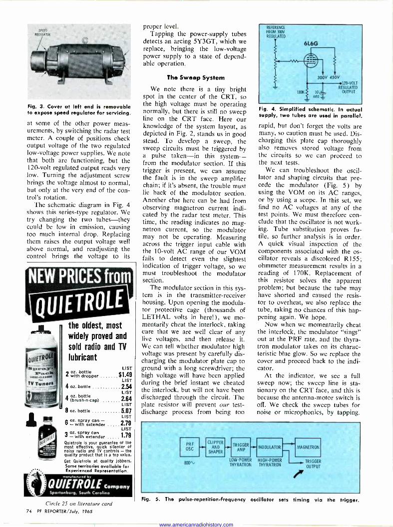
Fig. 3. Cover at left end is removable to expose speed regulator for servicing.
at some of the other power meas- urements, by switching the radar test meter. A couple of positions check output voltage of the two regulated low -voltage power supplies. We note that both are functioning, but the 120 -volt regulated output reads very low. Turning the adjustment screw brings the voltage almost to normal, but only at the very end of the con- trol's rotation.
The schematic diagram in Fig. 4 shows this series -type regulator. We try changing the two tubes-they could be low in emission, causing too much internal drop. Replacing them raises the output voltage well above normal, and readjusting the control brings the voltage to its
NEW PRICES from
QUIETROLE
1sF,x.ßír ]P'c..n
tb{tf<tf Mitt f4.
TV Tuner -
the oldest, most
widely proved and
sold radio and TV
lubricant
2 oz. bottle with dropper
4 oz. bottle
4 oz, bottle (brush.n-cap)
8 oz. bottle
LIST
$1.49 LIST
254 LIST
2.64 LIST
5 07 LIST
6 oz. spray can - -with extender 2.79
LIST
3 oz. spray can - with extender 1.79
Quietrole is your guarantee of the most effective, quick silencer of noisy radio and TV controls - the quality product that Is a top value.
Get Quietrole at quality jobbers. Some territories available for Experienced Representation.
menu, ecfored by
QU/ETROLE Company
proper level. Tapping the power -supply tubes
detects an arcing 5Y3GT, which we replace, bringing the low -voltage power supply to a state of depend- able operation.
The Sweep System
We note there is a tiny bright spot in the center of the CRT, so the high voltage must be operating normally, but there is still no sweep line on the CRT face. Here our knowledge of the system layout, as depicted in Fig. 2, stands us in good stead. To develop a sweep, the sweep circuits must be triggered by a pulse taken-in this system- from the modulator section. If this trigger is present, we can assume the fault is in the sweep amplifier chain; if it's absent, the trouble must lie back of the modulator section. Another clue here can be had from observing magnetron current indi- cated by the radar test meter. This time, the reading indicates no mag- netron current, so the modulator may not be operating. Measuring across the trigger input cable with the 10 -volt AC range of our VOM fails to detect even the slightest indication of trigger voltage, so we must troubleshoot the modulator section.
The modulator section in this sys- tem is in the transmitter -receiver housing. Upon opening the modula- tor protective cage (thousands of LETHAL volts in here!), we mo- mentarily cheat the interlock, taking care that we are well clear of any live voltages, and then release it. We can tell whether modulator high voltage was present by carefully dis- charging the modulator plate cap to ground with a long screwdriver; the high voltage will have been applied during the brief instant we cheated the interlock, but will not have been discharged through the circuit. The plate resistor will prevent our test - discharge process from being too
REFERENCE
FROM 300V REGULATED
6L6G
300V 450V
100K 10
mldiii
120 VOLT REGULATED
OUTPUT
Fig. 4. Simplified schematic. In actua supply, two tubes are used in parallel
rapid, but don't forget the volts are many, so caution must be used. Dis- charging this plate cap thoroughly also removes stored voltage from the circuits so we can proceed to the next tests.
We can troubleshoot the oscil- lator and shaping circuits that pre- cede the modulator (Fig. 5) by using the VOM on its AC ranges, or by using a scope. In this set, we find no AC voltages at any of the test points. We must therefore con- clude that the oscillator is not work- ing. Tube substitution proves fu- tile, so further analysis is in order. A quick visual inspection of the components associated with the os- cillator reveals a discolored R155; ohmmeter measurement results in a reading of 170K. Replacement of this resistor solves the apparent problem; but because the tube may have shorted and caused the resis- tor to overheat, we also replace the tube, taking no chances of this hap- pening again. We hope.
Now when we momentarily cheat the interlock, the modulator "sings" out at the PRF rate, and the thyra- tron modulator takes on its charac- teristic blue glow. So we replace the cover and proceed back to the indi- cator.
At the indicator, we see a full sweep now; the sweep line is sta- tionary on the CRT face, and this is because the antenna -motor switch is off. We check the sweep tubes for noise or microphonics, by tapping.
LOW
THYRATRON
i PR F
OSC
CLIPPER AND
SHAPER
TRIGGER AMP
MODULATOR MAGNETRON -
800\ -POWER HIGH -POWER
THYRATRON TRIGGER
OUTPUT
Spartanburg, South Carolina
Circle 25 on literature card 74 PF REPORTER/July, 1965
Fig. 5. The pulse -repetition -frequency oscillator sets timing via the trigger.
www.americanradiohistory.com

When we hit the second sweep amplifier, the sweep cuts out momentarily, so we replace the tube. The PRF oscillator exhibits a tendency to self -trigger, as evidenced by a thick double sweep line. To eliminate this tendency, we disconnect the trigger input lead and adjust the multivibrator bias control just beyond cutoff. With the trigger reconnected, the sweep should be stable. And it is.
At this point, we start the scanner turning by flip- ping the antenna motor switch on. The sweep line ro- tates until it reaches a point nearly at zero degrees (straight ahead), then stops. In a few seconds, a click is heard and the sweep proceeds in its rotation. This hesitation and click are caused by the deflection -coil drive synchro falling into step with the synchro in the scanner, so that as the scanner points in any particular direction, the sweep line will also be at that position on the face of the CRT. Since the sweep continues to rotate normally, we can assume that correct synchroni- zation has taken place and forget this point for now.
Marker Information We advance the Marker Rings control and note that
small, evenly spaced pips appear along the sweep line. As the sweep rotates, these markers trace concentric circles on the face of the CRT. We notice they are rather weak, and experience reminds us they should be strongly visible even at low settings of the control. Tube substitution in the marker stages is indicated; with two new ones, markers are visible at less than half the control rotation.
After setting the RANGE switch for the 20 -mile range, we turn up the variable marker control. The variable marker is a single pip similar to the fixed marker pips, but this one is movable by cranking a knob. The crank is geared to a Veeder-Root counter which is calibrated in miles. The counter is also connected to a 20K heli- pot which, when varied, changes the timing of the marker pip and puts it at a different location on the sweep.
Using the fixed range rings as a reference (these must never be tampered with in the field, as their ac- curacy is a matter of life or death to the navigator), we find that the variable marker does not track. That is, when the counter says 10 miles, the variable marker is not at the same point on the sweep as the 10 -mile fixed marker.
To calibrate the variable marker, we set the range switch to 1 -mile range and set the counter to read .5 mile. We adjust the ZERO -SET control to cause the variable marker to coincide with the 5 -mile fixed range ring. Next, we switch to the 20 -mile range and crank the counter to read 20 miles. We adjust the SLOPE control until the variable marker is superim- posed on the 20 -mile fixed range ring. These adjust- ments are interrelated so we repeat them until track- ing is accurate.
Fixed range rings are factory adjusted and usually sealed, or at least covered, to prevent tampering. No adjustment of these should ever be attempted by a technician, because only closely calibrated equip- ment and specific techniques can result in proper cali- bration. A little imagination can suggest the dire con- sequences of navigating with improper mileage -marker
PICTURE TUBES, TOO
SECO MODEL 88 TESTS ALL TUBES Tests all receiving tubes including novars, nuvistors, 10 pin types, compactrons, mag- novals-plus over 400 cathode ray picture tubes including 110° deflection types. Re- veals cathode emission, leaks, shorts, grid emission, gas error, filament continuity and cathode -to -heater emission.
MODEL 88 TUBE TESTER $7450
MODEL 98 HAS PLUG-IN CHASSIS
Plug-in socket chassis is easy to replace if it wears or if new tube types appear. Tests picture tubes and all re- ceiving tubes (over 2500 types)-re- veals same tube errors as Model 88 above.
MODEL 98 TUBE TESTER $992T
PICTURE TUBE ADAPTOR
INCLUDED
This picture tube adaptor with a 12 -pin socket fits over 400 cathode ray picture tubes including 110° deflection types. Comes with Model 88 and Model 98 Seco Tube Testers!
MODEL 107E FOR NO SET-UP TESTING
40 prewired sock- ets fit 63 tube bases-plus a plug-in 8 socket chassis wired to 14 lever type pin se- lectors. Gives three comprehen- sive tests-finds faults quickly.
MODEL 107B TUBE TESTER $18950 Write for full information today
SECO ELECTRONICS 1 2 21 S. Clover Drive Minneapolis, Minn. 55420
Circle 40 on literature card July, 1965/PF REPORTER 75
www.americanradiohistory.com

a new money -making, traffic -building tube tester
östomerl
THE ALL NEW SENCORE TC131
SEMI -AUTOMATIC TUBE CHECKER
After thousands of requests here is the "counter/bench" version of the famous Sencore Mighty Mite Tester; designed for the ultimate in tube checking thoroughness and oper- ational simplicity! Designed for two-way use - as a pro- fessional shop tester and customer self-service unit. Tests
over 2500 tubes - including Nuvistors, Compactrons, 10 -
pins, Novars, Magnovals and foreign tubes with a big 6 -inch meter for easy reading. Semi -automatic; simply turn function control to any test and watch lighted arrow on meter automatically stop on right scale. User can't go wrong - no guess work - everything is read right on the meter (no tricky neon lights to misread); only 3 set-up controls. Easy to read, speed -indexed set-up cards make every test fast and sure. Like the famous Mighty Mite, the TC131 uses 100-megohm grid leakage sensitivity to spot those "tricky" tubes other testers miss; tests inter -element shorts and makes cathode emission tests under full oper- ating levels. A real profit maker as a counter checker or self service tube seller in your shop . . . and it's only $129" See your distributor about the big TC131 trade-in deal.
professional quality - that's the difference!
426 SOUTH WESTGATE DRIVE ADDISON, ILLINOIS
Circle 41 on literature card 76 PF REPORTER/July, 1965
TRIGGER IN PULSE -FORMING DELAY LINO
FILAMENT»MR .
YIITH NIGH -VOLTAGE
NY INSULATION
i
OI SCONTEGT HERE BRIEFLY TO CHECK 1103
TRIGGER OT
PLANE TRANSFORMER
T103
MAG CURRENT
METER
Fig. 6. Mag current is "zero" with maggie disconnected.
calibration. Just to check operation, we go through the recom-
mended adjustments for the sweep circuits, first set- ting the 40 -mile gate control, then proceeding to ad- just the sweep lengths on each range.
Looking for Targets
Examination of our results so far shows we have a stable sweep, with range marks as they should be, but with no targets showing. Advancing the master gain control shows us good IF gain, since we have an effect similar to TV snow, but still no targets. We check to make sure the STC (Sensitivity Time Con- stant) control is not set so as to affect over-all gain, then proceed to try to locate the trouble which is keep- ing targets invisible.
We know the modulator is working, since we ser - iced it earlier. A check of magnetron current shows the meter to be pegged, so we switch the set to STAND-
BY. Study of the simplified schematic in Fig. 6 shows two likely causes: the magnetron could be drawing excessive current or pulse transformer T103 could be shorting internally. Disconnecting the plug to the mag- netron and switching the radar set to OPERATE, we again find the meter pegged: the transformer must be at fault. Luckily, we have one in our car, so we get it and install it.
When we start the set again, the meter is off the peg, but current is lower than normal, and we still have no targets. Reasoning says: weak modulator pulse or poor magnetron. A new modulator tube makes no difference, so we change the high -voltage rectifiers in the modulator cage. Magnetron current is now in the range recommended by the manufac- turer, so we replace the modulator cage cover. A glance shows targets on the CRT face in certain pie - shaped sections, but none in other sections. Let's see if we can figure out why.
This radar system uses an AFC circuit to eliminate the need for tuning the set each time it is used. The AFC circuit applies a search voltage to the klystron tuning circuit. If the klystron is not adjusted prop- erly, or the AFC circuit is not functioning correctly, this search voltage swings the klystron tuning back and forth across its operating mode. This hunting accounts for the targets that are shown as the klystron is tuned through a correct point by the AFC search voltage. As the sweep rotates around the CRT, the tuned points appear as pie sections between offtune points.
We try tuning the klystron, but still can't get the AFC to lock. With our 1 -ma meter scale, we check
www.americanradiohistory.com

AFC crystal current and find none. Replacing the crystal brings current up to a normal reading around .4 ma, but the AFC is still hunting.
Tuning Up
Now back to the klystron. Metering the signal - crystal current, we tune the klystron (Fig. 7) very care- fully. The klystron tuning tool is used to set the tun- ing screw maximum counterclockwise, which sets the klystron at the high -frequency end of its operating range. Be sure the AFC -MANUAL switch is on AFC, and the repeller -TUNING potentiometer is at the center of rotation. As you turn the klystron tuning screw slowly clockwise, signal -crystal current starts to rise and is pulsing (AFC hunting). As you continue to turn the screw slowly, a point is suddenly reached where hunting stops. The current is very low, but carefully turning the screw further brings a point of maximum crystal current. Stop here for now.
Reach up and switch the AFC switch to MANUAL, this disabling the AFC search voltage. The signal crys- tal current may drop considerably, so adjust the TUN- ING potentiometer to again find maximum crystal cur- rent. Now, flipping the AFC switch on and off should produce very little change. If it does, readjust the klystron slightly with AFC on, and touch up the po- tentiometer with AFC off.
The only other tuning adjustment is the TR tube. This is best tuned by looking at the CRT face and turning the TR tuning screw for maximum tarket brightness. In this installation, the CRT face can't be seen from the transmitter -receiver housing, so we can use a different method. This receiver provides an IF test point: using our VOM on its 2.5 -volt DC range, we connect the positive lead to the test point and the negative lead to ground. This provides only a very slight indication, but enough to tune the TR tube for maximum.
Miscellaneous Adjustments
Now we have targets galore on the screen but we notice the center is cluttered with echoes from nearby objects, which saturate the receiver. To eliminate this clutter, the radar is equipped with a circuit called the Sensitivity Time Constant (STC) circuit. Operat- ing the STC GAIN control on the front of the indicator clears this clutter }o we can see the outlines of the harber quite plainly.
We quickly check operation of the FTC or RAIN - SNOW switch. This Fast Time Constant circuit is a differentiator in the video amplifier which, when ac- tivated, causes the leading edges of larger targets to be accentuated, making very small targets less prom-
KLY STRON
TUNING SCREW .s
e
at last... instant color patterns at your finger tips. .
zero warm-up time
SENCOt E CDue DELUXE coas GENERATOR roo. ....owe ragmen noto oz. am',
,leo. 11111a -..111111..,.0 0
THE ALL NEW SENCORE CG135 DELUXE
TRANSISTORIZED COLOR GENERATOR
The big push is on in Color TV. Equip yourself now with the new, solid state Sencore CG135 and cash in on the zooming volume of new service business as Color -TV booms! Instant, service -ready RCA standard color bars, cross -hatch, white dots and individual vertical and hori- zontal bars enable you to set up or trouble -shoot more Color TV sets per day; earn top money in this fast growing service field. It's an analyzer too: Color gun interruptors, unmodulated video for chroma circuit trouble isolation and unmodulated sync pulses to keep Zenith receivers in sync for this test, make color trouble shooting a snap. Sturdy all -steel contruction for rugged, heavy duty in the field or shop. Another Best
Buy in profit -building service instruments from Sencore at $14995 COMPARE THESE FEATURES: SEE WHY THE CG135 IS IN A CLASS
BY ITSELF
Solid state construction employs high priced GE "Unijunctions" to
develop six "jump out proof counters" that guarantee stable patterns at all times with no warm-up Standard RCA licensed patterns as
shown on schematics throughout the industry Handy universal color gun interruptors on front panel Lead piercing clips insure non -
obsolescence CRT adaptors optional Crystal -Controlled 4.5mc
Sound Carrier Analyzing Signal to insure correct setting of fine tuning control RF output on Channel 4 adjustable to Channel 3
or 5 from front of generator when Channel 4 is being used No batteries to run down; uses 115 V AC Less than one foot square, weighs only 8 lbs.
professional quality - that's the difference!
NCCD 1=1 426 SOUTH WESTGATE DRIVE ADDISON, ILLINOIS
Fig. 7. Receiver "plumbing" shows klystron and TR tuning. Circle 42 on literature card
July, 1965/PF REPORTER 77
www.americanradiohistory.com

top money maker in the service business
NEW IMPROVED SENCORE CR133
CRT CHECKER & REJUVENATOR
The new, improved CR133 CRT Checker is designed to test all present picture tubes - and it's ready for future tubes too! Two plug-in replaceable cables contain all sockets required. The compact, 10 lb., CR133 checks CRT
emission, inter -element shorts, control grid cut-off capa- bilities, gas and expected life. Checks all tubes: conven- tional B&W, new low drive B&W, round color tubes and new rectangular color picture tubes. Exclusive variable G2 Volts from 25 to 325 Volts insures non -obsolescence when testing newly announced "semi -low" G2 CRT tubes. New Line Voltage Adjustment insures the most accurate tests possible. Uses well -filtered DC for all checks to avoid tube damage and reading errors. Color guns are indi- vidually tested as recommended by manufacturers. Ex- clusive automatically controlled rejuvenator applies re- juvenation (ACR) voltage as required by individual tube condition; precisely timed to prevent over -rejuvenation or tube damage. The ACR feature is most useful for color tube current equalization to insure proper tracking. Hand -wired and steel -encased for protection of meter and panel in truck or shop, the new improved CR133 is only . . .
The famous CR128 CRT Checker and Rejuvenator is similar to above, but with a three position G2 slide switch and without Line Voltage Adjustment at $69.95
professional quality - that's the difference!
426 SOUTH WESTGATE DRIVE ADDISON, ILLINOIS
inent. Thus, rain or snow squalls will not be as plain on the screen as targets having better reflectivity. This one is operating normally as indicated by breaking up of nearby targets (which consist of buildings and hills in the vicinity of the harbor).
Topside
Now to inspect the antenna, or scanner. Before ascending to the scanner mount, we look at the head- ing flasher on the screen of the indicator. The head- ing flasher is a momentary brightening of the sweep as the scanner passes through zero degrees relative, or straight ahead of the ship. This flasher should be positioned exactly 0° on the bearing ring surrounding the CRT face. In addition, some target of reference, which can be visually verified to be precisely straight ahead, should lie directly under the heading flash.
If the flasher coincides with a visual reference target, the flasher switch in the scanner is properly adjusted. If not, adjustment is needed. If the flasher is correct with respect to target, but does not occur exactly at 0° on the bearing ring, the entire picture is not truly oriented, and must be corrected by turn- ing one of the synchros slightly, preferably the one at the deflection coil in the indicator. Before chang- ing synchro position, be sure the flasher line is correct compared with an actual target (scanner switch ad- justment) .
Some radar systems are very difficult to adjust for proper synchronization. Improper synchronization is indicated by a loud click as the sweep goes through zero degrees, or by the sweep frequently sticking or jumping somewhere near zero. Occasionally the sweep will apparently synchronize, but the entire picture will be rotated several degrees one way or another. This is another sign of incorrect synchronization. In all cases of poor synchronization, follow the manufactur- er's instruction booklet very carefully and synchroni- zation can be achieved' with a minimum of trouble.
On the RADAR QUEEN, the heading flasher meets both requirments, and the sweep synchronizes nor- mally, so we proceed with our inspection of the scanner. We check the oil level, clean soot off the horn (with the radar off so as not to get a radiation burn), check for loose or worn parts. Adding a little oil as recommended by the manufacturer seems to be all the service this scanner needs, so we add it, but- ton the cover up, and climb back down.
All that remains is to make our entry in the radar maintenance log. This is done by recording the date and the hours on the radar running -time meter, list- ing parts installed, adjustments made, results of in- spection, writing in the license number, date, and name of the technician performing maintenance.
That's All
Other systems require the same approach to service, if a complete job is to be done. Some have fewer gim- micks, and some are arranged differently; but step- by-step analysis of the system, such as we've done here, will show the competent technician what needs to be done. Radar maintenance isn't difficult at all!
Circle 43 on literature card 78 PF REPORTER/July, 7965
www.americanradiohistory.com
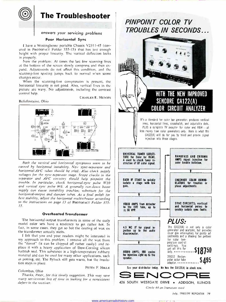
The Troubleshooter
answers your servicing problems
Poor Horizontal Sync
I have a Westinghouse portable Chassis V2311-45 (cov- ered in PHOTOFACT Folder 355-15) that has just enough height with proper linearity. The vertical deflection locks in properly.
Now the problem: At times the last few scanning lines at the bottom of the screen slowly compress and then ex- pand. Adjustments do not affect this condition, and the scanning -line spacing jumps back to normal when scene changes occur.
When the scanning -line compression is present, the horizontal linearity is not good. Also, vertical lines in the picture are wavy. No adjustments, including the contrast control help.
CHARLES E. HEDGES Bellefontaine, Ohio
Both the vertical and horizontal symptoms seem to be caused by horizontal instability. New sync -separator and horizontal -AFC tubes should be tried. Also check supply voltages for the sync -separator stage. Scope checks in the separator and AFC circuitry should help pinpoint the trouble. In particular, check horizontal -sync pulse W10 and vertical sync pulse W6. A generally run-down boost supply can cause instability troubles; substitute for the horizontal -output and damper tubes. As a final polish for best stability, adjust the horizontal multivibrator according to the instructions on page 13 of PHOTOFACT Folder 355- 15.
Overheated Transformer The horizontal -output transformers in some of the early
model color sets have a tendency to get rather hot. In fact, in some cases, they get so hot the coating of wax on the transformer actually melts.
I felt that you and your readers might be interested in my approach to this problem. I remove all the wax from the "donut" (it can be chipped off rather easily) and re- place it with a heavy application of Dow -Corning silicon bathtub seal. This substance is a high -temperature rubbery material and can be used for many other applications, such as potting, etc. The flyback still gets warm, but the insula- tion stays in place.
PETER F. HILLE Columbus, Ohio
Thanks, Peter, for this timely suggestion. This may save many serviceman lots of time in looking for a nonexistent defect in the receiver.
PINPOINT COLOR TV TROUBLES IN SECONDS...
V
WITH THE NEW IMPROVED
SENCORE CA122(A)
COLOR CIRCUIT ANALYZER
It's a standard ten color bar generator; produces vertical lines, horizontal lines, crosshatch, and adjustable dots,
PLUS a complete TV analyzer for color and B&W-at less money than color generators only. Here is what the
CA122(A) will do for you by tried and proven signal
injection into these stages.
UNIVERSAL TUNER SUBSTI- TUTE for Color (or B&W). A must to check tuner re- striction of RF color signal.
EACH IF STAGE to quickly isolate a stage with low gain.
t
VIDEO AMPS from detector to the CRT tube, up to ± 30 VPP.
BANDPASS AND CHROMA AMPS signal injection for color trouble isolation.
CHECKOUT COLOR DEMOD-
ULATORS for troubles or phase adjustments.
f
4.5 MC IF for signal in- jection up ta the audio discriminator.
AUDIO AMPS; 900 cycles for injection right up to the speaker.
SYNC CIRCUITS; vertical and horizontal pulses to quickly isolate sync faults.
PLUS: The CA122(A) is not only a color generator and analyzer, but provides color gun interruptors for purity ad- justments and a shading bar pattern for color tem- perature control settings. You get all this for only. $18150 39a2 Re
tube $495 guiarr color tub adaptor.
See your distributor today. He has the CA122(A) in stock now.
426 SOUTH WESTGATE DRIVE ADDISON, ILLINOIS
Circle 44 on literature card
July, 1965/PF REPORTER 79
www.americanradiohistory.com

add an fm -stereo service center with this one new
sencore unit!
,1« 101
LOU
THE SENCORE MX129 FM STEREO
MULTIPLEX GENERATOR & ANALYZER
FM -Stereo growth continues to mount and is fast becoming as big a field as Color TV. This means more FM -Stereo service business for you, now and in the future. Is your shop equipped? It can be - completely and economically - with the MX129, the FM -Stereo "Service Center in a
Case." The instantly stable, 19 -Transistor, crystal controlled MX129 is the most versatile, most portable (only 71/2
pounds), most trouble free and efficient multiplex unit on the market - just like having your own FM -Stereo trans- mitter on your bench or in your truck. Powered by 115 volts AC, it produces all signals for trouble shooting and aligning the stereo section of the FM receiver . . . can be used to demonstrate stereo FM when no programs are being broadcast. Self-contained meter, calibrated in peak to peak volts and DB, is used to accurately set all MX129 controls and as an external meter to measure channel separator at the FM -
Stereo speakers. NO OTHER EQUIP-
MENT IS REQUIRED. only $16950 SIGNALS AVAILABLE FOR ALIGNMENT, TROUBLE SHOOTING AND
ANALYZING: FM -RF carrier with composite multiplex audio signal with 38kc sup- pressed carrier, 19kc pilot and 67kc SCA signals Multiplex signal formed by 60 or 1000 cycle internal tones or any external signal
Full control over left and right channel amplitude (modulation) External 67kc SCA signal available for trap adjustment Composite
signals available for signal injection FM detector
professional quality - that's the difference!
426 SOUTH WESTGATE DRIVE ADDISON, ILLINOIS
Circle 45 on literature card
80 PF REPORTER/July, 1965
Instant Tube Burnout
I am having trouble with a Silvertone Chassis 528.51108 (covered in PHOTOFACT Folder 397-3) . The horizontal- multivibrator tube (6CG7) will burn out as soon as it is installed. The tube lights up very bright, ahead of the other tubes, when the set is first turned on. I have replaced the filament dropping resistor (R52, 51 ohms, 25 watts) and power -supply filters CIA and CIB but haven't been able to locate the trouble. Any help would certainly be appreciated.
MORRIS BOBO
Union, S. C.
1
SW ON
corNiBá ©(3
CIRCUIT Bi
eL
BUTTON
TO TUNER FILAMENTSC55 =.M]
® 51nEW
225V r RED IA
mid
Mu 55 151.1
1 ® ® ® n 12AX4GTA 12AV5GA 6CG7 6CM7 24AEP4e 5A05
S2VAC 5 AÔVAC /OVAC SVA
® ® ® ® 6198 5U8 611B8 5AM8 3BZ6
I9VAC
38Z6 ro Iona FItAMfM1' 3
NA IODUmmI o- 19WmmI
From the symptoms you mention, it seems the reason the 6CG7 (V9) is burning out immediately after instal- lation is that the socket is shorted at pin 5. This would account for the tube lighting brightly when the set is
turned on. However, there is a possibility that one of the decoupling capacitors located in the filament string is
shorted. Take a resistance measurement from pin 4 to ground and then from pin 5 to ground with the tube re- moved from the socket. There should be approximately 45 ohms from pin 5 to ground. If the resistance is con- siderably lower than this, there is evidently a short some- where in the filament string between pin 5 and ground.
Puzzler Solved
I am submitting this additional information in regard to the "Voltage Puzzler" on a Westinghouse TV Model H - K3821 (The Troubleshooter, April 1965 PF REPORTER,
page 75). I have had several of these sets-and other receivers
having a similar type of horizontal -oscillator circuit- with the same trouble symptoms. The common cathode resistor, R91, greatly increases in value and causes the plate voltage to decrease. I have found replacing this re- sistor with a 1 -watt unit prevents future trouble. Also, in some instances, I have found C3 (10-mfd electrolytic) to cause the same trouble. Both of these components are logical suspects as causes of horizontal -oscillator trouble.
D. W. ALLEESON Los Angeles, Calif.
Thanks, D. W., for letting our readers share your ex- periences and the remedies you have found for these troubles.
www.americanradiohistory.com

COLOR COUNTERMEASURES
Symptoms and service tips from actual shop experience
27K 210%
elhfr \ . © CHANGÉ 1
"A 4. 5 P6&j0 47K
U L9
mc 000 iii
3900
10%
7pt - Spf
.01
beg 410%
lOK ' 10% D22
-5% 470pf
v6 A V 6HL8 2.2még CATHODE FOLLOWER
9'
VIDEO - PEAKING
o REMOVE
AND REVERSE THE 2 OUTSIDE LEADS ON
R5 A (FRONT( BRIGHTNESS CONTROL
X REMOVE CONNECTION
250V ADD CONNECTION AND CAPACITOR
TO ARM DELAY I
LINE 01
200
000 L '
_ 5%
101 10OR 220 =
OA 70K
v7 T2GN7 Y AMP
290V
2
220 i10%
Z
140V
3,9
CONTRAST
T200mtd 25V
63-5323
o 390V
3.3meg
BRIGHTNESS 2.2 (FRONT)
ADD 5401(
TOPIN9 O OF 6U10 OR PIN 7
(6FQ7-6CG71 DISCONNECT REMOVE
ADD POT. & 820K
390V
Chassis: Zenith 26KC20, 25LC20, 25LC30 Symptom: Excessive brightness causes blooming and poor focus or low brightness. Tip: Install brightness range control (Zenith part No. 63- 5323) and make following circuit modification, consisting of eight simple steps: 1. Remove R36 (68K) from one side of the brightness con- trol to ground. Reverse the two outside leads on the bright- ness control (black -white and white). Remove the B+ resistor (R31) connecting the black -and -white lead from the brightness control to the 390 V line. 2. Remove the 27K resistor located between the 4.5 -mc trap (terminal A on L7) and the white wire leading to the brightness control. Disconnect the end of C24 (.01 mfd) fastened to this point. Run a length of hook-up wire from terminal A on the 4.5 -mc trap to a blank lug on the terminal strip adjacent to the 12GN7 tube socket. Install a 47K resis- tor between this end of the wire and R12 (220K) at the junction on the terminal strip with the blue wire leading to the center tap of the brightness control. 3. Remove C24 (.01 mfd) loosened in step 2. 4. Replace the .01-mfd capacitor in step 3 from ground to the junction of the terminal strip of the 47K resistor, the 220K resistor (R12), and the blue wire leading to the center tap of the brightness control. 5. Connect a 560K resistor from the black -and -white lead on the brightness control to pin 9 of the 6U10 horizontal - discharge tube. (In 26KC20 chassis-Pin 7 of the 6FQ7 or 6007.) 6. Mount a 100K brightness range control (Zenith part No. 63-5323) midway between the circuit breaker and the AC interlock at the rear of the chassis. (On the 26KC20 chassis use the blank cut-out nearest the set-up switch.) Mount the control so the lugs are readily available for soldering. Look- ing at the back side of the control with the lugs facing down, ground the right-hand lug by soldering it directly to the chassis. Run a piece of hookup wire from the center lug on the range control to the white wire leading to the brightness control. Connect a hookup wire from the re- maining lug to a blank lug on the terminal strip nearest the horizontal discharge tube. Install an 820K resistor between this hookup wire and the 390 V B+ line. 7. Rotate the channel selector to a station signal and set the brightness and contrast to maximum. 8. Adjust the brightness range control just below the point at which the raster tends to "bloom." Raster lines should be distinct.
just in time for the fm and uhf boom!
an all transistorized field strength meter. -
THE ALL NEW SENCORE FS134
FIELD STRENGTH METER
Once again, you can turn to the roof tops for a fast dollar in antenna installations. But this time, you can do it the easy way. No more running up and down ladders, locating cumbersome AC extension cords, lugging heavy tube operated field strength meters on the roof, or worse yet, getting the shock of your life from the AC line as you hold onto a soil pipe. Here is a new portable field strength meter to fill your every need in VHF, UHF or FM antenna installations. Many customers want all antennas on one mast thus creating interaction. Here is where the FS134 goes to work. You can optimize antenna location and orientation in seconds. Just connect the antenna, tune in the station and adjust. Self-contained speaker blasts forth the sound from the TV or FM station to insure that you have the exact signal that you are looking for. The FS134 is so light weight (only 9 lbs.) that you can take it with you up the chimney if necessary. Get rid of the assistant at the other end of the transmission line and the needless "yelling" back and forth. Get the FS134 today . . .
only $1995° COMPARE TO ANY OTHER FIELD STRENGTH METER
AT TWICE THE MONEY Sensitivity . . . 5 microvolts on VHF and FM, 15 microvolts on
UHF Input impedance . 300 ohms or 75 ohms with plug-in transformer 500 KC band width Powered by easy to get "C" cells 4 inch meter with 2 percent accuracy calibrated in DB and microvolts.
professional quality - that's the difference!
426 SOUTH WESTGATE DRIVE ADDISON, ILLINOIS
Circle 46 on literature card July, 1965/PF REPORTER 81
www.americanradiohistory.com

SAVES your back...
SAVES your time .. .
1
14- 47" --si I !
SHORTY DOLLY for RADIO and TV
just 47 inches high for STATION WAGONS and PANEL PICK-UPS
FOLDING PLATFORM 151/4" x 241/2" top. Snaps on or off.
(Platform only) $11.95
FURNITURE PAD
Designed for TV, radio and appliance men who make deliveries by station wagon or panel truck ... the short 47 inch length saves detaching the set for loading into the "wagon" or pick up. Tough, yet featherlight alu- minum alloy frame has padded felt front, fast (30 second) web strap ratchet fastener and two endless rub- ber belt step glides. New folding platform attachment, at left, saves
your back handling large TV chassis or table models. Call your YEATS
dealer or write direct today!
1 1 i '5Giellidde COVER AND PADS
YEATS semi fitted covers are made of tough water repellent fabric with adjustable web straps and soft, scratchless white flannel liners. All shapes and sizes - Write
YEATS Model No. 5 Height 47"
Weight 32 lbs.
TV COVER
APPLIANCE DOLLY SALES COMPANY
1307 W. Fond du Lac Ave. Milwaukee, Wisconsin
Circle 53 on literature card
TECHNICANS ... Open the
Door to Greater TV Profits
robe. .....
Rebuild Color - Black and White - Bonded Face Television Picture Tubes in
YOUR OWN SHOP
Send today for 16 page bro- chure describing haw you can capture the television picture tube rebuilding market in your area. low investment of $3,290.00 and up. Financing available. Training at our plant included in low price. Get start- ed today toward greater profit tomorrow.
VACATION BONUS When on vacation plan to stop
by and see a complete demon-
stration. If purchase is made
while you are here Windsor will pay equivalent to your tour- ist rate plane fare from your
U.S. home and baik with the
exception of Alaska and Hawaii.
WINDSOR ELECTRONICS, INC. Equipment Division
999 N. Main St., Glen Ellyn, Illinois
PFR Bench
Report
:iïi! .-': w ::'
"Magic -Wand" Degausser
Not so very long ago, during a local dealer showing of the new line of Zenith home -entertainment instruments. Jack Clouse, color merchandising manager for the Zenith distributor
w -
in our area, called us over to a color set with a large area of severe impurity. While several of us stood around the set, Jack took a small device from his jacket pocket and passed it once or twice across the face of the CRT. Presto! The impurity disappeared as if by magic.
Jack's rather dramatic demonstration was followed by a clos- er look at the "magic wand," which proved to be a small. magnetically polarized powdered -iron wheel mounted to a short plastic handle by a "U" -shaped bracket which allowed the wheel to spin freely. The wand's degaussing action is initiated by spinning the wheel, thus setting up a rapidly rotating magnetic field which redistributes the field in the vicinity of the CRT into a random pattern. In use, the wand is spun rapidly, passed back and forth in front on the CRT about an inch or two away. When the entire screen has been covered, the wand is with- drawn while the wheel is still spinning.
We subsequently found the wand he gave us useful for re- storing purity to several sets which had picked up some con- tamination while being moved around our lab area. It should come in real handy for house -call problems of impurity result- ing from electrical -appliance magnetization or other common household sources.
The Zenith part No. is S67714, and the degausser is avail- able from Zenith distributors and dealers. The price is $2.50.
Circle 52 soil literature card
82 PF REPORTER/ July, 1965
www.americanradiohistory.com

Product Report
For further information on an', of the following items, circle the associated number on the Catalog & Literature Card.
i, Dual -Element Screen Yagi (124)
For TV service requiring high gain at 210 to 216 mc, TACO provides a screen - type yagi, Model SY-42-13, having a gain of 13 db. Front -to -back ratio is several times better than that of an ordinary yagi. Direct coaxial input for either 50 or 75 ohms is provided by an internal
balun. VSWR is 1.5:1; power rating is
2040 watts. The reflector measures 60" x
60"; the frame is fabricated from 11/4" square aluminum, and the screening is of 3/s" diameter tubing. Yagi elements are 1/2" diameter with 5/s" reinforcing sleeves. Combining lines provide a single coaxial input.
Bass Compensator (125)
A "bass energizer" designed to compen- sate for low -frequency deficiencies in small speakers by providing an increase (relative to the rest of the spectrum) in very -low bass level is being manufactured by Altec Lansing for distribution through its high-fidelity outlets.
The device, designated as the Altec 100A Bass Energizer, requires no elec- trical power and connects between the amplifier output and speaker input. It can he attached either to the back of the speaker enclosure or next to the ampli- fier, whichever is more convenient for the user.
The compensation becomes effective only below 150 cps and builds to full efficiency from 60 cps down to speaker cutoff. Though designed to operate with
25-50 me
37 WATTS
FCC TYPE
ACCEPTED
Vt ORDERS; Y'U FIEED
NMfs ob - Ê
MIVe:
. 4 Power -Packed! E.gineered for Rugged Business Use!
Excellent performance, dependability and operational convenience Drovided by FM -40 reflect the experience and design ability that has made Sonar the undis- puted leader in this demand ng form of business radio art. Greater range be-
cause of Voice -Power designed circuitry Compact and lightweight Easily installed in smallest vehicles Smartly styled for office use
Noise free squelch for crisp clear communication Accessory plug for Sonar Call, selective Calling System Accessory plug for high power Linear Amplifier 12 VDC & 117 VAC 1 year warranty Size: 43/4"H x 91/2" x 111/4"L Weight: 10 lbs.
BR21
FOR AD I I POWER LINEAR RF AMPLIFIER is a matching companion to cover greater distances with increased transmit power. Available for either base or mobile.
Complete I pr. of Crystals, Power Mike, Brackets, & 2 power cables $28950
SONAR RADIO CORPORATION 73 Wortman Ave., Brooklyn 7, N.Y. oept.412 Please send me information on Business' Radio FM -40 and BR -21 matching Amplifier.
Name.
Address
City Zone .. State
efficient speakers, the unit can be used with inefficient speakers if the amplifier power is adequate. Consumer net price is $30.
Pocket Voltmeter (126)
A new vest -pocket -sized voltmeter known as the "Mini -Test" is being offered by IEH Mfg. Co., Inc. The new device. Model VT -101, can be used to check TV sets, radios, and other electrical appli- ances. It can also be used to trace open lines, shorts, and blown fuses. Range of the "Mini -Test" is from 65 to 800 volts, AC or DC; the VM is priced at $1.49.
Miniature Soldering Iron (127)
Small size and a four -second heating time are features of the "miniscope" soldering iron. The tip can remain cold until it touches the soldering point, a characteristic designed to help eliminate burning of adjacent wires, terminals, or insulation in cramped spaces. The iron operates from a 2 -volt supply to reduce the danger of voltage leakage damaging delicate tran- sistors. It is normally used with a transformer, but can be battery operated when an AC source is not available. The Parker Trading Co. tool weighs 13/4 oz.
Circle 48 on literature card July, 1965/PF REPORTER 83
www.americanradiohistory.com

USE YOUR AC POWER TOOLS
HIGH`
Low or anywhere with
TERADO PACKAGED ELECTRIC POWER Provides 117 Volts, 60 Cycle AC
... just like any wall outlet!
COMPLETE, SELF-CONTAINED POWER SUPPLY _',,, inverter, battery and automatic charger; not dependent on car battery.
OPERATES: Electric Drills, $69.50 Soldering Irons, User's Price Other Hand Tools, Model 50.160 "Trav-Electric" Test Equipment, Lights, Tape Recordars, Record Players, Portable TV, and much more! Unexcelled source of emergency power! 60 cycle frequency stable within lh cycle, regardless of load. Recharges from car cig- arette lighter or A.C. recepta- cle. Wt. 30 lbs., including bat- tery. Copper clad steel case, -rte 12" x 51/2" x 8".
Other models to 600 watts capacity. ' ) FOR FURTHER INFORMATION, WRITE
t' CORPORATION 1073 Raymond Ave., St. Paul, Minn. 55108
Circle 49 on literature card
Antenna Accessory (128)
The "Tenna-Mate" (Model 3D -M) is a self -adhering TV antenna accessory, de- signed specifically for receivers with built-in antennas, developed by Snyder Mfg. Co. The unit is designed to im- prove picture reception by portable TV receivers. The accessory is affixed to the side of a set with a pressure adhesive. It needs no electrical outlet and is at- tached to the antenna elements with small clamps. It is priced to retail at $4.95.
Field -Strength Meter (129)
Field surveys, antenna checks, and gain measurements can be made with the Sadelco, Inc. Model FS -2 field -strength meter. It provides two bands, one for channels 2 to 6 and FM. and the other for channels 7 to 13. UHF coverage is available through the plug-in addition of Sadelco's UA -1 Adaptor.
Gain measurements can be made in terms of microvolts or db. Picture and sound carriers are clearly marked, and provision is made for peak carrier read- ings. Four db scales provide 1 db resolu- tion from -33 to +60 db. Each scale is read directly, with no calculations re- quired, from a semilogarithmic scale.
The printed -circuit unit is fully tran- sistorized and battery operated. The in- strument measures 81/4" x 41/2" x 3'r and
. .= ,,...
4.111 CAPACITORS
./
TYPE IL ... why use old fashioned wax end -filled card- board capacitors in radio re-
pairs? Avoid call-backs with Planet type IL dual section tub-
ular electrolytics ... hermetically sealed in aluminum tubes with wax impregnated insulating jacket. Planet IL's are also avail- able in 450 volts for TV servic-
ing. Ask for them oy type number
at your distributcr.
PLANET SALES CORP. 225 Belleville Ave.
Bloomfield, New Jersey
Circle 55 on literature card
84 PF REPORTER/July, 1965
REMEMBER WHEN -other guy wire SNARLED
WRIGHTTV GUY WIRE never did.
WRIGHT TV GUY WIRE... Comes in 50' connected coils Has bright, long-lasting galvanized finish
Four strand No. 20 Six strand No. 20 Six strand No. 18 No. 3 -Cushion center Seven strand - No. 18 Aluminum All in 50' connected coils
Also on metal and wooden reels
G. F. WRIGHT Wholesalers - Stocks nearby
STEEL & WIRE COMPANY W O RCESTER. MASS.
Circle 50 on literature card,ediellil www.americanradiohistory.com

weighs 31/2 lb. The price of $295 includes a carrying case which provides space for phones, matching transformers, adapter cables, etc. The price also includes the two 9 -volt batteries necessary for oper- ation.
Motorized Winch for Crank -Up Towers (130)
By means of the winch shown here, an operator can control by push-button op- eration the up-and-down movement of a Rohn Manufacturing Co. HD Series crank -up tower. The complete system consists of the winch, a heavy-duty weather-proof geared motor, and a con- trol unit. Fuses and a reset device are utilized for protection of the motor. while limit switches are employed to prevent damage to the tower when up or down travel limits are reached.
The Rohn Model 200 remote control unit, an optional feature, can be added to enable the operator to control the movement of the tower from a remote point. This unit includes a tower -height indicator.
Cable Shield and Filter (131)
The Electro -Shield Filter and shielded cable by Estes Engineering Company provides a waterproof 30 -amp 100-VDC filter with optional lengths of shielded cable. The filter provides noise -free power cables for such DC electronic equipment as two-way radios. depth indicators. di- rection finders. etc. The filter eliminates power -cable noise and thereby provides improved electronic and communications reliability.
ALL PARTS
(except tubes)
Plus Shipping Charge
950 QUALITY 24 hrs. TV TUNER Service
SERVICE Most Makes
UHF - VHF - COLOR - (COMBOS. - 14.50) 15 YEARS OF TUNER EXPERIENCE
1 Year Warranty Tuners completely cleaned and checked
Open Account on approved credit
Dist. write for price structure
Pack Tuner Carefully - Insure Package - Include all parts (Broken or not)
QUALITY TUNER SERV. 5142 W. 25th St.
CHICAGO, ILL. 60650
('ire le 5h ,nn literature <nrd
ALLIANCE
TennasRotor
for Single Bay
t CB beam
antennas
Tenna-Rotor stands up under severe conditions. Tests prove it is the strongest, most durable antenna rotator available for Citizens Band use on all single bay vertically polarized antennas up to six elements.
This latest Alliance Tenna-Rotor will turn heavy antennas and is designed to withstand wind velocities to 90 m.p.h. in accordance with E.I.A. wind loading standards. The patented rigid offset design distributes the load resulting in superior strength to weight ratio for greater ease of installation.
Features anti-windmilling, gearing and brake system to maintain positive positioning and eliminate overtravel. Unit, enclosed in a sturdy, ribbed die-cast zinc housing, is lightweight and simple to set up. If you can lift your antenna and put it on the Tenna-Rotor ... it will support it, hold it and turn it.
New Precision Machined Steel Drive Gear e Greatest Positioning Accuracy Possible
The new Alliance transistorized automatic C-225 features a patented phase -sensing bridge similar to laboratory test equipment and is now -
available exclusively from Alliance for CB users. Affords automatic, stepless, synchronous pinpoint positioning accuracy throughout 360° of rotation that reduces or eliminates interference.
All this with noiseless control. O
e" The ALLIANCE Manufacturing Company, Inc. (Subsidiary of Consolidated Electronics Industries Incorporated) Alliance, Ohio Útil CSA approved
('hele 5/ on literature card July, 1965/PF REPORTER 85
www.americanradiohistory.com

There's a tool right here for any soldering need.
And you know it's best because it's from
Dual Heat Soldering Guns. Weller guns reach full soldering temperature up to 40% faster than other guns. Up to 28% greater solder- ing efficiency. Two trigger positions let you switch instantly to low heat for soldering near heat -sensitive components-or high heat when you need it. Spot- light illuminates work. Three models cover all needs:
100/140 watts-Model 8200 - $5.95 list 145/210 watts-Model D-440 - $9.95 list 240/325 watts-Model D-550-$10.95 list
"Pencil" Soldering Iron. Small, lightweight, efficient. A 25 -watt, 115 volt iron that weighs only 134 ounces. Yet it does the work of irons that weigh twice as much and have much higher wattage. You can hold and maneuver it as easily as a pencil. Recovers heat rapidly. Maximum tip temper. ature 860°F. With 'W' screwdriver tip and cord. Model W-PS-$5.20 list.
Temperature -Controlled Low -Voltage Soldering Pencil. New! For universal soldering including heavy-duty chassis work. Temperature control is in the tip. Interchangeable tips give a choice of 500°F, 600°F, 700°F and 800°F controlled temperatures. Operates on 24 volts. Small, lightweight, highly efficient. Complete with 3/6" 700°F tip and 60 watt, 120 volt, 50/60 cycle power unit which has stand for soldering pencil attached. Model W-TCP-$26.00 list.
AT YOUR ELECTRONIC PARTS DISTRIBUTOR
WELLER ELECTRIC CORP., EASTON, PA. In Canada: Weller Electric Corp., 121 Counter Street, Kingston, Ontario
WORLD LEADER IN SOLDERING TECHNOLOGY
Circle 54 on literature card
Miniature "Walkie-Talkie" (132)
"Walkie-talkies' so small they fit in the palm of the hand are being added to Westinghouse Electric Corporation's 1965 transceiver line. The Citizens band units have a range of three miles, depending upon terrain, making them suitable for person -to -person communications while hunting, camping or boating, in construc- tion work, and around the house. The new units measure 4 5/16" x 21/2" x 11/a".
Each transceiver, enclosed in an ano- dized aluminum case, is powered by a single nine -volt battery and contains eight transistors, one diode, and one ther- mistor. In addition, the tiny transceiv- ers are equipped with 10 -section whip antennas. The units are expected to sell in gift -packed pairs for less than $80, including leather carrying cases.
Two -Way Business Radio (133)
The "Courier 50 FM" is a two-way FM business radio designed to provide small- business and professional men with two- way contact with off -premises personnel. The transceiver is engineered to operate in the 25 -to -50 me range with an output of 50 watts. It is available with either an AC or a 12 -volt DC power supply. The unit, made by E.C.I. Electronics Communications, Inc., has been type accepted by the Federal Communications Commission. List price is $279.50.
86 PF REPORTER/July, 1965
www.americanradiohistory.com

INDEX TO ADVERTISERS
JULY 1965
ATR Electronics, Inc. 13
Alliance Mfg. Co. 85
Amphenol-Borg Corp. 49
B & K Mfg. Co. 45, 47 Div. of Dynascan Corp.
Berns Mfg. Co., Inc., The 70
Bussmann Mfg. Div. 20, 21
Castle TV Tuner Service 18
Centralab, Div. of Globe -Union, Inc. 58
Channel Master Corp. 53
Cleveland Institute of Electronics 19
Delco Radio Div. 61
Electro -Voice, Inc. 50
Finney Co. 14, 57
GC Electronics Co. 60
General Electric 51
Hickok Electrical Instrument Co. 15, 17
JFD Electronics Corp. 42, 43
Jerrold Electronics Cover 2
Lectrotech, Inc. 13
Littelfuse, Inc. Cover 4
Lubra Clean 12
Mallory, P. R., & Co., Inc. 69
Miller, J. W., Co. 51
Mosley Electronics, Inc. 52
Philco Corp. 63
Planet Sales Co. 84
Precise Electronics 62
Precision Tuner Service 70
Quality Tuner Service 85
Quam-Nichols Co. 48
Quietrole Co. 74
RCA Electronic Components and Devices 59, Cover 3
Sains, Howard W., & Co., Inc. 60, 73
Sarkes Tarzian, Inc. Tuner Service 9
Seco Electronics, Inc. 75
SENCORE, Inc. 76, 77, 78, 79, 80, 81
Sonar 83
Sonotone Corp. 64
Sprague Products Co. 11
Sylvania Electric Products, Inc. 55
Terado Corp. 84
Texas Crystals 70
Triplett Electrical Instrument Co. 71
Ungar Electric Tools 56
Weller Electric Corp. 86
Windsor Electric Co. 82
Winegard Co. 22, 23, 87
Wright, G. F., Steel & Wire Co. 84
Yeats Appliance Dolly Sales Co., Inc. 82
Zenith Radio Corp. 16
Replacements for Color -TV ADG Components (134)
A packet consisting of two variable re- sistance components (one thermistor and one varistor), which are designed to pro- vide replacements for defective units in color -TV sets using automatic degaussing circuits. Packet identification number of this Workman product is 50.
New Literature Technical Booklets You Can Buy
Featuring
Easy to Understand TYPICAL
LAYOUTS MOTELS
FOR
ER SHOW RHOTELS HOMES A FDA AR TV
COURTS APARTMENTS
Ty RECEPTION AREAS
Master TV Systems Handbook (135)
Jerrold Electronics Corp. offers the "TV Distribution Systems Handbook." This new guide to master TV antenna systems covers 150 typical layouts for motels, hotels, homes, dealer showrooms, apart- ments, and trailer courts. The booklet is primarily for servicemen who are in- terested in making money in the MATV field. It gives practical installation and servicing hints along with design theory. The handbook is priced at $1.00 from Jerrold Electronics Corp., 15th and Le- high Ave., Philadelphia 32, Pa.
mn egard Dealer
of the Month
No. 38 of a series
Dick Seiler says: "Our town of Mendon is in a rural fringe area where we must have the pulling power of Winegard Colortrons."
Winegard salutes Seiler Tele- vision Service, Mendon, Michigan, and their distributor, Electronic Supply Corporation, Battle Creek, Michigan.
Dick Seiler started in the television business way back in 1949 and, since 1961, has operated his own store in the prosperous rural area of Mendon, Michigan. After 16 years of experi- ence, working with all types of TV antennas, Dick says, "I can depend on Winegard Colortron to deliver excellent TV signal every time in color or black and white. When I sell a new color set, I want it to perform as well in the home as it did on my demonstration floor ... so I always recommend and install Winegard Antennas."
The confidence Dick Seiler has shown in Winegard comes from installing Winegard products and seeing them in action. He is one more important service dealer who knows Winegard's standards of excellence first hand.
Winegard Co. ANTENNA SYSTEMS
D3000H Kirkwood Burlington, Iowa
Circle 136 on literature card July, 1965/PF REPORTER 87
T -'-'T 1 if www.americanradiohistory.com

FREE Catalog and Literature Service
*Check "Index to Advertisers" for fur- ther information from these companies.
Please allow 60 to 90 days for delivery.
ANTENNAS & ACCESSORIES
58. ANTENNACRAFT - Literature on new 75 -ohm TV and FM antennas for use with RG -59/U coaxial cable.
59. FINNEY-Catalog 20-322 showing new- est addition to the All -Band Color -Ve - Log series of UHF -VHF -FM antennas.*
60. JERROLD - 16 -page booklet describing latest TV -FM reception aids; includes an- tennas, antenna amplifiers, amplified cou- plers, UHF converters, and home distri- bution systems.*
61. JFD-Literature on complete line of log - periodic antennas for VHF, UHF, FM, and FM streo. Brochure showing con- verters, amplifiers, and accessories; also complete '64-'65 dealer catalog plus dealer wall chart of antenna selection by area.*
62. MOSLEY ELECTRONICS - Illustrated catalog giving specifications and features on large line of antennas for Citizens band, amateur, and TV applications.*
63. STANDARD KOLLSMAN - Catalog sheet on Model TA transistorized UHF converter and transistor converter kit.
64. TRIO -Brochure on installation and ma- terials for improving UHF transistor re- ception.
65. ZENITH - Informative bulletins on an- tennas, rotors, batteries, tubes, loudspeak- ers, record changers, and wire and cable.*
AUDIO & HI-FI 66. ADMIRAL - Folders describing line of
'65 equipment; includes black -and -white TV, color TV, radio, and stereo hi-fi.
67. ELECTRO -VOICE --New booklet cover- ing sound reinforcement as it applies to the new changes in the Catholic Church liturgy.
68. GC ELECTRONICS - New up-to-date phono wall chart, No. FR -250-W, includ- ing new drives and hundreds of newly cross-referenced models.*
69. JENSEN - 24 -page catalog, No. 165-K, illustrates and describes speakers and speaker system kits.
70. NUTONE-Two full -color booklets illus- trating built-in stereo music systems and intercom -radio systems. Includes specifi- cations, installation ideas, and prizes.
71. OAKTRON - "The Blueprint to Better Sound," an 8 -page catalog of loudspeakers and baffles giving detailed specifications and list prices.
72. OXFORD TRANSDUCER -Product in- formation bulletin describing complete line of loudspeakers for all types of sound applications including replacements for public address and intercom systems.
73. QUAM-NICHOLS - Automotive speaker guide listing replacement speakers for all automobiles from 1954 through 1965 for both front- and rear -seat applications.
74. SAMPSON-Full-line four-color catalog page showing transistor radios and tape recorders.
75. SONOTONE-Specification sheet on new Sonomaster speaker system, Model RM -2, sheet No. SAH -96.
76. FICO -Data sheet on Model 753 Tri - Band transceiver and other ham gear, plus full -line catalog.
COMMUNICATIONS 77. GENERAL RADIOTELEPHONE - Lit-
erature on Models BB -30 business radio, MC -8 and VS -6 CB transceiver, CG -3 frequency counter, and 615-B CB watt- meter.
78. PEARCE-SIMPSON - Specification bro- chure on IBC 301 business -band two-way
radio, Companion 11, Escort, and Guardian 23 Citizens -band transceivers.
COMPONENTS
79. BUSSMANN -Bulletin SFH-9 on fuse and holder combination designed for use where identification of open circuit must be positive. GBA fuse has a red -tipped indicating pin that extends from end of fuse when fuse opens. HLD holder has transparent knob to permit indicating pin on open fuse to be seen clearly.*
80. COMPONENT SPECIALTIES - Bro- chure on intercoms, speakers, earphones, and other Speco products.
81. EBY SALES -Literature on new socket adapters and conversion harnesses for 90° color tubes.
82. E -Z -HOOK -Catalog sheets showing com- plete line of test connectors, harness -cable board binding posts, and test leads and clips.
83. IEH-Catalog of 12 solid-state circuit modules.
84. INTERNATIONAL ELECTRONICS - New listing of IEC electron tubes.
85. J -B -T -INSTRUMENTS -General catalog 565; bulletins on reed relays, osscillator controls, toggle switches, and subminia- ture rotary -lever switches.
86. LITTELFUSE - New circuit breaker cross reference brochure.*
87. RAWN - Detailed instruction sheets on TV knob and plastic repairs with Plas-T- Pair.
88. SPRAGUE - Latest catalog C-616 with complete listing of all stock parts for TV and radio replacement use, as well as Transfarad and Tel-Ohmike capacitor an- alyzers.*
89. SWITCHCRAFT-New product bulletin No. 151 describes series 3600 coaxial video
jacks and plugs.
90. TRIAD -1965 replacement catalog and television guide on transformers for tele- vision, hi-fi, home and auto radios.
91. VACO - Terminal catalog featuring all new styles and types.
92. WALDOM -Latest catalog No. 6F5 cov- ering solderless terminals and connectors, hardware, tube sockets, terminal strips, knobs, dials, and service replacement parts. Includes index and prices.
SERVICE AIDS 93. CASTLE -How to get fast overhaul serv-
ice on all makes and models of television tuners is described in leaflets. Shipping in- structions, labels, and tags are also in- cluded.*
94. CHEMICAL ENGINEERING - Litera- ture on new Ever -quiet contact cleaner.
95. INJECTORALL-1965 catalog No. 65 on electronic chemicals.
96. LUBRA CLEAN -Information on new tuner cleaner.*
97. PRECISION TUNER -Literature supply- ing information on complete, low-cost re- pair and alignment services for any TV tuner.*
98. YEATS - The new "hack -saving" appli- ance dolly Model 7 is featured in a four - page booklet describing fester -weight aluminum construction.
SPECIAL EQUIPMENT 99. ATR - Descriptive literature on selling
new, all -transistor Karadio Model 707, having retail price of $29.95. Other liter- ature on complete line of DC -AC invert- ers for operating 117 -volt PA systems and other electronics gear.*
100. GREYHOUND - The complete story of the speed, convenience, and special service provided by the Greyhound Package Ex- press method of shipping with rates and routes.
101. PERMA-POWER-New Catalog on all - transistor garage -door operator with pulse - tone modulation.
102. TERADO-Bulletin on Tras' Electric Model No. 50-160 transistorized DC -AC power inverter.*
103. VOLKSWAGEN - Large, 60 -page illus- trated booklet, "The Owner's Viewpoint," describes how various VW trucks can be used to save time and money in business enterprises, including complete specifica- tions on line of trucks.
TECHNICAL PUBLICATIONS 104. CLEVELAND INSTITUTE OF ELEC-
TRONICS -Free illustrated brochure de- scribes electronic slide rule with four les- son Instruction Course and grading serv- ice.*
105. RCA INSTITUTES - 64 -page book, "Your Career in Electronics" detailing home study courses in telecommunications, industrial electronics, TV servicing, solid- state electronics, and drafting. Preparation for FCC license, and courses in mobile communications and computer program- ming also available.*
106. HOWARD W. SAMS - Literature de- scribing popular and informative publica- tions on radio and TV servicing, com- munications, audio, hi-fi, and industrial electronics, including special new 1965 catalog of technical books on every phase of electronics.*
TEST EQUIPMENT 107. B K -Bulletin 108-R on Model 801 Ca-
pacitor Analyst. Bulletin No. 124-R on Model 1240 color generator. Catalog AP - 21R describing uses for and specifications of Model 1076 Television Analyst, Model 1074 TV Analyst and Color Generator, Model 700 and 600 Dvna-Quik Tube testers. Model 445 CRT Tester -Rejuve- nator, Model 960 Transistor Radio An- alyst, Model 360 V -O -Matie VOM, Model 375 Dynamic VTVM and other test in- struments.*
108. HICKOK-Specification sheets on Model 662 installer's color generator, Model 677 wideband scope, Model 470A uni -scale VTVM, and Model 799 Mustang tube tester.*
109. JACKSON -Complete catalog describing all types of electronic test equipment for servicing and other applications.
110. LECTROTECH - Bulletins on Meter- gards, Lectrocells, Models V-6 and V-7 color -bar generators, and Model T-100 horizontal -deflection circuit meter.*
111. MERCURY - Full catalog showing new kits for Models 501, 1101, 1101A, and 1400.
112. RCA COMPONENTS -Bulletin on RCA WR -52A stereo FM signal simulator (form 1Q1130).*
113. SECO -Eight page tube -tester brochure includes specifications and prices.*
114. SENCORE-Information on all solid- state color generator Model CG135 plus full line catalog.*
115. SIMPSON - Complete 16 -page brochure on entire line of electronic test equipment; also, catalog on line of panel meters.
116. TRIPLETT-New test equipment catalog No. 47-T with information on all Triplett VOMs, VTVM's, tube testers, transistor analyzers, signal generators, and related accessories.*
117. WATERMAN-Technical data on OCA - 11A industrial scope and OCA -12A dual
trace scope.
TOOLS
118. ENTERPRISE DEVELOPMENT -Time- saving techniques in brochure from En - deco demonstrate improved desoldering and resoldering techniques for speeding up and simplifying operations on PC hoards.
119. LUXO LAMP - Information on Model LVT-2 low voltage lamp with movable extension arms.
TUBES & TRANSISTORS
120. SEMITRO\ICS - Bulletins describing new No. TV1000 UHF transistor and
No. CTV358 color crystal.
88 PF REPORTER/July, 1965
www.americanradiohistory.com

RCA announces a zero defects program
through...
ersonal
uality
erformance
RCA's effort to apply some of the concepts of missile -type
reliability to the production of commercial receiving tubes
You lose time and money whenever a tube fails.
To minimize such losses, RCA has initiated still another quality control measure to guard
against tube failure and keep profits in your pocket.
It's our ZERO DEFECTS program, an attempt to eliminate as far as possible the factor of
human error from commercial receiving tube production.
RCA personnel engaged in the production of RCA receiving tubes have voluntarily signed a
pledge of PERSONAL QUALITY PERFORMANCE...a pledge to strive for error -free perform-
ance in every task they undertake in the making of RCA receiving tubes.
Their pledge is one more assurance to you of tube reliability and greatest possible reduction
in callbacks when you sell and install RCA receiving tubes.
RCA Electronic Components and Devices, Harrison, N.J.
elkThe Most Trusted Name In Electronics e
www.americanradiohistory.com

et.
EXACT REPLACEMENT
direct from factory to you
PART NO. 8152.75
CIRCUIT BREAKER EXACT REPLACEMENT
FOR COMPLETE LISTING SEE
BACK OF CARD
LITTELFUSE DES PLAINES ILLINOIS
Complete range of high quality circuit breakers to cover every replace- ment need, packaged for your convenience individually on a display card or 5 per box.
Also,available in10card assortment (9 separate ratings) or 10 breakers per unit box (9 separate ratings).
packaged for your particular needs
Li TTELFUS EDES PLAINES, ILLINOIS
i., "_..i
Circle 57 an literature card
www.americanradiohistory.com