A volume-averaged two-phase model for transport...
13
A Volume-Averaged Two-Phase Model for Transport Phenomena during Solidification J. NI and C. BECKERMANN A basic model of the transport phenomena occurring during solidification of multicomponent mixtures is presented. The model is based on a two-phase approach, in which each phase is treated separately and interactions between the phases are considered explicitly. The macro- scopic transport equations for each phase are derived using the technique of volumetric aver- aging. The basic forms of the constitutive relations are developed. These relations link the macroscopic transport phenomena to microscopic processes such as microstructure development, interfacial stresses, and interfacial heat and mass transfer. Thermodynamic relations are pre- sented, and it is shown that nonequilibrium effects can be addressed within the framework of the present model. Various simplifications of the model are examined, and future modeling needs are discussed. I. INTRODUCTION IN order to predict the structure and composition of a solidifying material, it is important to model not only the mass, momentum, heat, and chemical species trans- port phenomena on a macroscopic scale but to properly account for the evolution of the solid structure and the transport phenomena on a microscopic scale. This paper describes a general model of the transport phenomena occurring during solidification of multicomponent ma- terials that allows for intimate coupling between the pro- cesses occurring on macroscopic and microscopic scales. Due to the presence of complex interfacial structures that characterize solidification of most multicomponent materials (i.e., alloys), it is usually impossible to solve the exact conservation equations on a microscopic scale. Instead, macroscopic models of the transport phenomena are utilized that can be derived by averaging the micro- scopic (exact) equations over a finite sized averaging volume that contains both solid and liquid. This volume, shown in Figure 1, is much smaller than the system and large compared to the characteristic size of the interfacial structures. The resulting averaged or macroscopic equa- tions of each phase need to be supplemented by consti- tutive relations that describe the interactions of a phase with itself and the other phase(s). It is, however, not necessary to perform a formal averaging process to ob- tain a macroscopic description of solidification transport phenomena. Hills et al.,[l[ Prantil and Dawson, ]2] and Bennon and Incropera t31 utilized mixture theory to pos- tulate macroscopic equations without reference to any microscopic equations. Although it may be possible to deduce the necessary terms in the macroscopic equations without using an averaging process, there are a number of advantages to averaging, which are discussed by Drew. [41 Essentially, averaging shows how the various terms in the macroscopic equations arise and how the resulting macroscopic variables are related to the micro- scopic ones. This gives considerable insight into the for- J. NI, Research Assistant, and C. BECKERMANN, Assistant Professor, are with the Department of Mechanical Engineering, The University of Iowa, Iowa City, IA 52242. Manuscript submitted July 2, 1990. mulation of constitutive relations and holds the key for incorporating the evolution of the solid structure and the transport phenomena on a microscopic level into a macroscopic model. Beckermann and Viskanta iS] have taken this approach to derive a model of columnar den- dritic solidification of binary mixtures. In general, the averaging procedures and the form of the resulting equa- tions are well established and have been utilized in the modeling of a large variety of multiphase systems.[4.6.7] Very recently, Ganesan and Poirier [8] adopted this tech- nique to derive the mass and momentum equations for flow through a stationary dendritic mushy zone. They follow the derivations given by Gray and co-workers [9,1~ in the context of flow through porous media and present more general forms of the momentum equation used by Beckermann and Viskanta. fS] Previous models of solidification transport phenomena have been reviewed by Viskanta and Beckermann. tH] First, most models assume the velocity of the solid phase to be equal to zero or postulate some ad hoc relationship between the liquid and solid velocities, and only a single momentum equation is solved. In other words, a true two-velocity model of solidification has not been imple- mented before. This may be important if one considers, for example, floating and settling of small equiaxed crystals during the initial stage of solidification. In ad- dition, in some solidification processes (e.g., rapid so- lidification of sprays, rheocasting), the solid undergoes forced motion. One difficulty in the modeling of solid movement is due to the fact that the solid fraction, as well as the geometrical parameters associated with the microstructure, is advected with the solid. Solid fraction models that include solid movement presently lack any consistent theoretical basis. Second, many macroscopic models assume complete thermal and chemical equilib- rium between all parts of the solid and liquid phases in the averaging volume. A true two-temperature (or en- thalpy) and two-species concentration model of solidi- fication has not been implemented in the past. The equilibrium assumption is, generally, not valid for so- lidification of multicomponent mixtures, as there usually exist strong species concentration gradients in the solid on a microscopic scale (i.e., microsegregation). In ad- dition, such equilibrium models are unable to account METALLURGICAL TRANSACTIONS B VOLUME 22B, JUNE 1991-- 349
Transcript of A volume-averaged two-phase model for transport...
A Volume-Averaged Two-Phase Model for Transport Phenomena during Solidification
J. NI and C. BECKERMANN
A basic model of the transport phenomena occurring during solidification of multicomponent mixtures is presented. The model is based on a two-phase approach, in which each phase is treated separately and interactions between the phases are considered explicitly. The macro- scopic transport equations for each phase are derived using the technique of volumetric aver- aging. The basic forms of the constitutive relations are developed. These relations link the macroscopic transport phenomena to microscopic processes such as microstructure development, interfacial stresses, and interfacial heat and mass transfer. Thermodynamic relations are pre- sented, and it is shown that nonequilibrium effects can be addressed within the framework of the present model. Various simplifications of the model are examined, and future modeling needs are discussed.
I. I N T R O D U C T I O N
IN order to predict the structure and composition of a solidifying material, it is important to model not only the mass, momentum, heat, and chemical species trans- port phenomena on a macroscopic scale but to properly account for the evolution of the solid structure and the transport phenomena on a microscopic scale. This paper describes a general model of the transport phenomena occurring during solidification of multicomponent ma- terials that allows for intimate coupling between the pro- cesses occurring on macroscopic and microscopic scales.
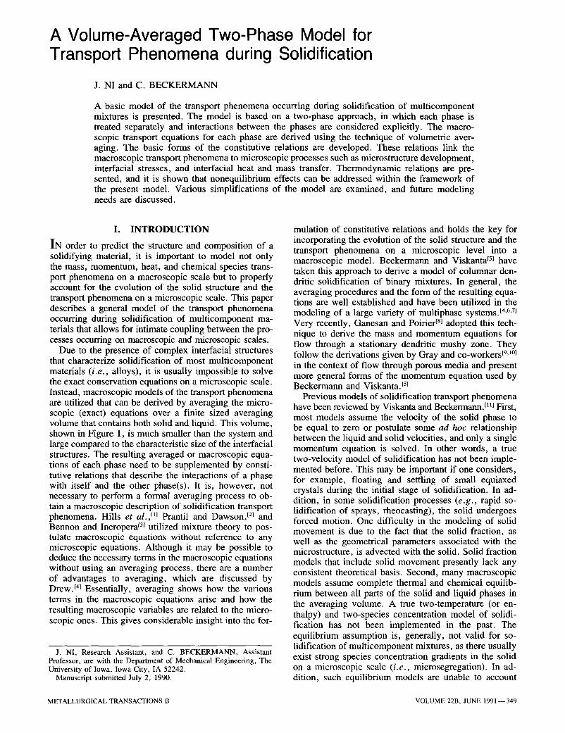
Due to the presence of complex interfacial structures that characterize solidification of most multicomponent materials (i.e., alloys), it is usually impossible to solve the exact conservation equations on a microscopic scale. Instead, macroscopic models of the transport phenomena are utilized that can be derived by averaging the micro- scopic (exact) equations over a finite sized averaging volume that contains both solid and liquid. This volume, shown in Figure 1, is much smaller than the system and large compared to the characteristic size of the interfacial structures. The resulting averaged or macroscopic equa- tions of each phase need to be supplemented by consti- tutive relations that describe the interactions of a phase with itself and the other phase(s). It is, however, not necessary to perform a formal averaging process to ob- tain a macroscopic description of solidification transport phenomena. Hills et al.,[l[ Prantil and Dawson, ]2] and Bennon and Incropera t31 utilized mixture theory to pos- tulate macroscopic equations without reference to any microscopic equations. Although it may be possible to deduce the necessary terms in the macroscopic equations without using an averaging process, there are a number of advantages to averaging, which are discussed by Drew. [41 Essentially, averaging shows how the various terms in the macroscopic equations arise and how the resulting macroscopic variables are related to the micro- scopic ones. This gives considerable insight into the for-
J. NI, Research Assistant, and C. BECKERMANN, Assistant Professor, are with the Department of Mechanical Engineering, The University of Iowa, Iowa City, IA 52242.
Manuscript submitted July 2, 1990.
mulation of constitutive relations and holds the key for incorporating the evolution of the solid structure and the transport phenomena on a microscopic level into a macroscopic model. Beckermann and Viskanta iS] have taken this approach to derive a model of columnar den- dritic solidification of binary mixtures. In general, the averaging procedures and the form of the resulting equa- tions are well established and have been utilized in the modeling of a large variety of multiphase systems.[4.6.7] Very recently, Ganesan and Poirier [8] adopted this tech- nique to derive the mass and momentum equations for flow through a stationary dendritic mushy zone. They follow the derivations given by Gray and co-workers [9,1~ in the context of flow through porous media and present more general forms of the momentum equation used by Beckermann and Viskanta. fS]
Previous models of solidification transport phenomena have been reviewed by Viskanta and Beckermann. tH] First, most models assume the velocity of the solid phase to be equal to zero or postulate some ad hoc relationship between the liquid and solid velocities, and only a single momentum equation is solved. In other words, a true two-velocity model of solidification has not been imple- mented before. This may be important if one considers, for example, floating and settling of small equiaxed crystals during the initial stage of solidification. In ad- dition, in some solidification processes (e.g., rapid so- lidification of sprays, rheocasting), the solid undergoes forced motion. One difficulty in the modeling of solid movement is due to the fact that the solid fraction, as well as the geometrical parameters associated with the microstructure, is advected with the solid. Solid fraction models that include solid movement presently lack any consistent theoretical basis. Second, many macroscopic models assume complete thermal and chemical equilib- rium between all parts of the solid and liquid phases in the averaging volume. A true two-temperature (or en- thalpy) and two-species concentration model of solidi- fication has not been implemented in the past. The equilibrium assumption is, generally, not valid for so- lidification of multicomponent mixtures, as there usually exist strong species concentration gradients in the solid on a microscopic scale (i.e., microsegregation). In ad- dition, such equilibrium models are unable to account
METALLURGICAL TRANSACTIONS B VOLUME 22B, JUNE 1991-- 349
(a)
ever, they rely on relatively simple equilibrium mixture equations for the macroscopic transport phenomena; in other words, the effects of the microscopic phenomena on the macroscopic transport are neglected other than through the evolution of the latent heat. In addition, the validity of the modified solid fraction models for con- vective transport of liquid and solid has not been established.
The foregoing considerations have prompted us to de- rive a two-phase (i.e., two-velocity, two-enthalpy, and two-species concentration) model of solidification trans- port phenomena using a formal volume-averaging pro- cedure. As mentioned above, such two- (or multi-) phase models are well known; however, their rigorous appli- cation to common solidification systems is new. The equations presented are valid for convective transport of both liquid and solid and incorporate directly non- equilibrium effects between the phases and the various undercoolings. The basic forms of the constitutive re- lations for the phase interaction terms in the macroscopic equations are also provided. It is emphasized that much additional research is necessary to incorporate the com- plex microscopic phenomena present in alloy solidifi- cation into the constitutive relations. Finally, relationships between the present and previously utilized models are discussed, and areas for future research are outlined.
(b)
Fig. 1 - -Schemat ic illustration of the averaging volume containing (a) columnar dendritic crystals and (b) equiaxed dendritic crystals.
for undercooling of the liquid near the solidification front, which makes their use difficult for modeling of nucle- ation phenomena, microstructure formation, growth of (equiaxed) crystals that are completely surrounded by the (undercooled) melt, and other nonequilibrium effects/~21 The inclusion of undercoolings due to microscopic tem- perature and species concentration gradients in the liquid is of utmost importance for the prediction of micro- structure formation, because the undercoolings may, in turn, be related to the dendrite tip or eutectic front ve- locity and, ultimately, to the dendrite tip radius, dendrite ann spacings, or lamellar spacings, t131 The equilibrium assumption has also been made partially responsible for considerable disagreement between predictions obtained from such models and experimental data. E5,~4,~5} A com- parison of various equilibrium models with regard to their ability to predict macrosegregation has recently been made by Voller eta/. [16l They also show how microsegregation can be accounted for in an "equilibrium" model; how- ever, the required modifications to the mixture species conservation equation are only valid for a stationary solid. Recently, Rappaz I~2} reviewed a number of micro- macroscopic models of columnar and equiaxed solidi- fication of dendritic and eutectic alloys. These models include nucleation and the various undercoolings by in- troducing special solid fraction models. Much insight into the prediction of microstructure formation has been gained through the use of micro-macroscopic models. How-
II. VOLUME AVERAGING
The macroscopic conservation equations for each phase are obtained by averaging the microscopic (exact) equa- tions over the volume, Vo, shown in Figure 1. This av- eraging volume must be much smaller than the system and large compared to the characteristic size of the inter- facial (i.e., micro-) structures. Ll~ Under typical solidi- fication conditions, the system and interfacial structures are of the orders of 10 ~ to 10 -1 m and 10 -4 to 10 -5 m, respectively, so that the size of the averaging volume can vary between 10 -2 and 10 -3 m . Each phase k in Vo oc- cupies a volume Vk and is bounded by the interracial area Ak. The term nk is the outwardly directed unit normal vector on the interface Ak, and wk is the velocity of the interface Ak. For completeness, all averaging operators and theorems are given below. All of the information presented in this section is directly extracted from Ishii, t6J Hassanizadeh and Gray, t~~ and Drew. t41 The details of some of the derivations are also shown by Ganesan and Poirier. i8~
The definition of the volume average of some quantity in phase k is
(*k) = ~ Xk*k dV [ 1 ]
where Xk is a phase function, being equal to unity in phase k and zero otherwise. The intrinsic volume aver- age is defined as
<q,k) k = ~ xk,I,~ dV [21
350--VOLUME 22B, JUNE 1991 METALLURGICAL TRANSACTIONS B
For ~ = 1, we obtain from Eq. [ 1 ] the definition of the volume fraction ek as
v~ e~ = -- [31
Vo
In addition, it follows that
E e~ = 1 [41 k
and
<~e~> = e~<,I,~> ~ [51
The fluctuating component of ~k is defined as
+~ = ( ~ - <~)*)X~ [61
and the average of the product of two quantities ~k and qb~ is given by
(~I'k~k) ~ = (~k)~(~k) ~ + (%k+k) ~ [71
Finally, we have the following averaging theorems re- lating the average of a derivative to the derivative of the average:t~8,191
(o% Ot / = Ot Vo * * w k ' n ~ e A
k
[81
(V~k) --- V(~k) + < Vkn~ dA [91 k
(V 'k ) -- etV(qtk) k + < ~tkn~ dA [101 k
From a comparison of Eqs. [9] and [10], we also get
~ofA(~} '~)~nkdA=--(ald 'k)~Ve~ [11] k
and for ~k = 1, we have
< n k dA = -Ve~ [121 k
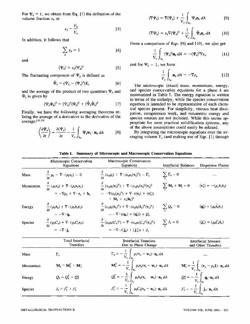
The microscopic (exact) mass, momentum, energy, and species conservation equations for a phase k are summarized in Table I. The energy equation is written in terms of the enthalpy, while the species conservation equation is intended to be representative of each chem- ical species present. For simplicity, viscous heat dissi- pation, compression work, and volumetric energy and species sources are not included. While this seems ap- propriate for most practical solidification systems, any of the above assumptions could easily be relaxed.
By integrating the microscopic equations over the av- eraging volume Vo (and making use of Eqs. [ 1] through
Table I. Summary of Microscopic and Macroscopic Conservation Equations
Microscopic Conservation Macroscopic Conservation Equations Equations Interfacial Balances Dispersive Fluxes
0 0 - Ok + V. (Pkvk) = 0 -- (emk) + V. (emk(Vk) k) = Fk ~ Fk = 0 - - Ot Ot k
O 0 -- (pkVk) + V" (OkVkVD -- (ekpk(v~) k) + V. (ekpk(vk)k(vk) k E Mk + M, = 0 (x~) = --(P.Vk~k) Ot c3t k
= -Vpk + V . ~ + bk = -V(ek(p~)b + V - ( % ) + (~)) + M k + e k ( b k ) k
o o - - ( p k h k ) + V " ( p k h k V k ) - - ( ekPk(hk ) k) + V " ( ekpk (hk )k (Vk ) ~) E Q~ = 0 (q~) = (p~ /~) Ot Ot
= -V-qg = - V . ((q,O + (q,~)) + Qk
-- (p~CD + V. (p~C~v~) Ot
= - V "j~
Mass
Momentum
Energy
Species 0_
(~w~(c~>b + v . (~w~(c~y(v~) ~) ~ Jk = o Ot k
= - V . ((jk) + (j~)) + Jk
Total Interfacial Interfacial Transfers Interfacial Stresses Transfers Due to Phase Change and Other Transfers
Fk F~ = - < pk(v~ - w~)" nk dA __ k
M~ = M r + M~ M r = - ~ p~v~(v~ - w ~ ) ' n k dA k
O~ = Qr + Q~ ark = - ~ o~h~(v~ - w~). n~ dA k
Jk = J r + J{ j r = _ < pkCk(Vk -- Wk) "nk dA k
Mass
Momentum
Energy
Species
M~ = (% - pkl)" n, dA k
Qq = - qk " n~ dA k
oL J ~ = - j k" nk dA k
M E T A L L U R G I C A L T R A N S A C T I O N S B V O L U M E 22B, J U N E 1991 - - 351

[10]), one obtains the corresponding macroscopic equa- tions for phase k and interracial balances. They are also summarized in Table I. These equations are valid in every region of the multiphase system (including the pure solid and liquid regions). Due to the averaging process, in- tegrals over the interfacial area arise in the equations that account for the interactions of phase k with the other phase(s). For simplicity, it is assumed that the correla- tion between the fluctuating components of Pk and ~k, i.e., (~k~k), is zero, and (pk) k is simply denoted by Pk. Alternatively, one could define density-weighted vari- ables; E4a~ however, the resulting form of the equations is virtually identical. In Table I, Mi is the interfacial mo- mentum source due to surface tension. No other inter- facial sources are assumed to be present.
III. C O N S T I T U T I V E RELATIONS
The macroscopic conservation equations and inter- facial balances presented in Table I are valid for any multiphase system. By specifying constitutive relations for the stresses, fluxes, and interfacial transfer terms, the equations can be adapted to model a specific physical system. The physical system considered here consists of the solid (s) and liquid (1) phases of a multicomponent material. Therefore, we have
�9 e ~ + et = 1 [ 1 3 ]
A~ = A t = A i [14]
w~= wl = w [15]
and
Fs = -F I = F [16]
A. General Considerations Regarding the Momentum Equations
Special care needs to be taken in deriving constitutive relations for the solid and liquid momentum equations. For this purpose, it is useful to consider two limiting cases: (1) the solid forms a continuous structure that is attached to a (cooled) wall (as in columnar growth) and (2) the solid is completely surrounded by and moves in the liquid (e.g., small equiaxed crystals). In general, there will be smooth transitions between the above two cases, as free crystals may be captured by a wall or by an ex- isting continuous solid structure and as parts of a con- tinuous solid structure (e.g., dendrite arms) may remelt and break off. In addition, with increasing solid volume fraction, equiaxed crystals will interact, merge, and eventually form a continuous structure ("packing").
In the present study, the solid is treated as a pseudo- fluid. The crystal interactions are accounted for in the interfacial momentum transfer and macroscopic stress terms (see below). If the solid forms a continuous struc- ture, the solid viscosity in these terms is assumed to be equal to infinity; i.e., stresses and deformations in a con- tinuous ("rigid") solid structure are not considered. If the solid does not form a continuous structure, the solid viscosity takes on values between zero and infinity, de- pending on the nature of the crystal interactions (Sec-
tions I I I -C and E). Through proper choices of the solid viscosity, it may also be possible to model capturing of solid crystals and crystal breakoff.
Before constitutive relations for the stresses, fluxes, and interfacial transfer terms are developed, the macro- scopic momentum equations and interfacial balance are rewritten and pressure relations are discussed.
It has become customary to separate various parts of the total interfacial stress M~ given in Table I as [6'17,2~
M~ = ~ (% - pkI)" nk dA = +PkiVek + M~ [171 k
where M~ is the dissipative part of the interracial stress and Pki is the average interracial pressure of phase k. The first term on the right-hand side of Eq. [17] can be inter- preted as a buoyant force due to the average interracial pressure,/Yk~. The term M~ contains the dissipative inter- facial forces due to viscous and form drag and unbal- anced pressure distributions leading to lift and virtual mass (acceleration) effects t4~ and is modeled below.
The difference between the interfacial pressure of the liquid and solid phases is due to surface tension, i.e.,
(l~si - - e l i ) : 0"~ [181
where or is the surface tension and ~ is the mean cur- vature of the solid/liquid inte_rface. The mean curvature of the solid/liquid interface ~ is directly related to the interfacial area concentration, Ai/Vo (see below). The pressure difference between the two phases is of the order of 100 MPa for crystals of a radius of 1 /xm. t13} It was mentioned earlier that the interfacial momentum source M~ is also due to surface tension. In view of the aver- aging theorem given by Eq. [12], Mi may be modeled a s [6]
Mi = ~ o'(ns dA = -o'~Ve, [19] i
Substitution of Eqs. [17] through [19] into the interfacial momentum balance (Table I) gives
M r + M/r + M, a + Mr = 0 [20]
Next, a relationship between the average interfacial pressure, Pk~, and the intrinsic average pressure of phase
k k, (p~), needs to be found. Due to instantaneous micro- scopic pressure equilibration in the liquid, we can write
(Pt) l =/Yt~ [21 ]
As long as the solid crystals are completely surrounded by liquid and there are no contacts between crystals, we have
(p,>" = g,, [221
However, if there is significant contact between (equiaxed) crystals or if the solid forms a continuous structure (e.g., in columnar growth), an additional pressure can be trans- mitted through the solid, if the solid is in contact with a wall. If an additional pressure is present, both Eqs. [18] and [22] need to be modified. At the present time, we assume that the natural state of the solid phase, in the absence of liquid pressure, is stress free. With Eqs. [17], [21], and [22], the macroscopic momentum
352- -VOLUME 22B, JUNE 1991 METALLURGICAL TRANSACTIONS B
equation (Table I) for both phases can now be written a s
0 (ekpk(Vk)k) + V" (ekpk(Vk)k(Vk) k) ---- --ekV((pk) k) Ot
+ V . (('rk) + ('t'k)) + M r + Me + ek(bk) k [231
B. Modeling of the Interfacial Transfers due to Phase Change
The exact expressions for the interfacial transfers of mass, momentum, heat, and species due to phase change are provided in Table I. Physically, these terms represent advection of an interfacial quantity of phase k due to phase change. In view of the mean value theorem for integrals, the terms can be modeled as the product of the interfacial area concentration, Sv = AJVo, and a mean interfacial flux. Hence, the interfacial mass transfer rate due to phase change becomes
F~ = - F t = F = Svp~rP~s [24]
where ff,s is defined as the average interface velocity, relative to the velocity of the solid phase, normal to the interface, and in a direction outward of the solid (~P,~ > 0 for solidlfication). In other words, rP,, represents the normal interface velocity solely due to phase change. The interfacial area concentration, AJVo, characterizes the first-order geometrical effects and is discussed in more detail below. Similarly, the interfacial momentum, heat, and species transfers due to phase change can be mod- eled, respectively, as
M r = VkiFk [25]
o r =/~k~Fk [26]
j r = CkiF k [27]
where the overbar denotes an average over the interfacial area, A~, in Vo. Through a mass balance at the interface, one can derive the following model for the difference between the average interfacial velocities of each phase: t61
Vsi Vii Pl -- Ds { Vs~ 2 Fs
PsPI
For translational motion of rigid solid crystals, we also have that
v~i = ( v y [29]
If the solid crystals have rotational motion, Eq. [29] is not valid; however, this effect is probably not too im- portant in most solidification systems of practical inter- est. Equations [25], [28], and [29] constitute a complete model of the interfacial momentum transfer due to phase change. It can be seen that this interfacial momentum exchange is proportional to the density difference be- tween the phases. In many solidification systems, the volume change upon phase change is relatively small (as opposed to liquid/vapor or solid/vapor systems), so that the interfacial momentum transfer due to phase change may be neglected in comparison to the dissipative inter- facial stress. This was also done by Ganesan and Poirier.tSl In that case, the interfacial momentum balance
(Eq. [201) reduces to M, a = -M~. It is important to re- alize, however, that in rapid solidification processes, the interfacial momentum transfer due to phase change can be large and should not be neglected.
The interfacial enthalpies and species concentrations appearing in Eqs. [26] and [27] are obtained from thermodynamic relations, which is discussed in detail in Section IV.
C. Modeling of the Interfacial Stress and Heat and Species Transfers
The exact expressions for the interfacial stress, M~, heat transfer, Qq, and species transfer, J~, are given by Eq. [17] and in Table I. Physically, these terms represent the transport phenomena between the phases within Vo by convection and/or diffusion. The interfacial transfers are due to microscopic velocity, temperature, and spe- cies concentration gradients on each side of the solid/ liquid interface, Ai. Similar to the interfacial transfers due to phase change, they can be modeled as the product of the interfacial area concentration, Sv, and a mean interfacial flux. As a first approximation, it can be as- sumed that the mean interfacial flux is, in turn, directly proportional to the difference between the interfacial av- erage and the intrinsic volume average of a quantity of phase k; i.e., ~ki -- (~k) k- In other words, the differ- ence ~k~ - (~k) k is assumed to be the driving force for the interfacial fluxes. More complete expressions for the driving force, that include higher order terms, can be found in the literature.t4,7j In writing the models for the interfacial transfer terms, we will follow accepted defi- nitions of various drag, heat, and mass transfer coefficients.
It is customary to model the dissipative part of the interfacial stress, Me, of the solid phase for flow around moving solid particles and of the liquid phase for flow through a continuous solid structure (i.e., porous media- type f low). [4,21] The interfacial stress needs to be mod- eled for one phase only, because the one for the other phase can be obtained from the interfacial momentum balance (Eq. [20]). In writing the following constitutive relations for the interfacial stress, it is assumed that re~i rG~ = ( v y (see Section B), so that the driving force for the interracial stress is simply proportional to the differ- ence between the intrinsic volume-averaged velocities of the solid and liquid.
For crystals moving in the melt, the dissipative inter- facial stress, M, a, can be modeled by introducing a drag coefficient, Co, as [4]
1 1 Mas - p ~ A a f o l ( v ) s -- (vl>l[ ((Vs> s -- (Vl) l) [30]
Vo2 where Ad is the total projected area of the solid phase, which is related to the interfacial area through a shape factor. In the above equation, the solid is assumed to be isotropic, and lift and virtual mass effects are neglected for simplicity. The drag coefficient should be obtained from suitable correlations (e.g., Stokes' law) as a func- tion of a "two-phase" Reynolds number defined as
I<v~>' - ( v y [ d~p~ Re = [311
/Xm
METALLURGICAL TRANSACTIONS B VOLUME 22B, JUNE 1991 - - 3 5 3
where dd is an effective drag diameter given by d d = 3Vs/2A d and/xm is a mixture viscosity which may be cal- culated from t22~
/xm =/xt(1 - e,) -a [321
where a is some positive number (~2.5). This way, it is possible to account for the presence of multiple crys- tals and crystal interactions within the averaging volume on the microscopic flow and, hence, the interfacial drag. For e~ = 1, the Reynolds number approaches zero, and the interfacial drag is infinitely large. On the other hand, for es = 0, the interfacial drag is equal to zero.
Flow through a mushy zone consisting of a continuous solid structure, such as columnar dendritic crystals or packings of equiaxed crystals, is usually very slow (i.e., it has a small Reynolds number), due to the high value of the interfacial area concentration. Therefore, the dis- sipative interfacial stress may be modeled in analogy with Darcy's law as [211
M/a = - e ~ / - t l K (2)-' " ((v/) t - (Vs) s) [331
where K (:) is a symmetric permeability tensor that con- tains the interfacial area concentration implicitly. Co- lunmar dendritic crystals are anisotropic, so that the permeability tensor contains at least two different com- ponents. On the other hand, equiaxed structures are iso- tropic, and the permeability tensor reduces to a scalar quantity. Values of the permeability have been reported for both equiaxed and columnar dendritic structures (see Poirier [231 and references therein). The permeability should approach zero and infinity for es = 1 and 0, respectively, which may be accomplished by utilizing the Kozeny- Carman equation. Ganesan and Poirier ~$1 include a second- order resistance term in Eq. [33] that is proportional to the square of the relative velocity. This term only exists for anisotropic solid structures. On the other hand, Beckermann and Viskanta E51 include a velocity square term to account for possible inertia (or "kinetic") effects on the interfacial stress. Their term is usually called Forchheimer's extension to Darcy's law and also exists for isotropic solid structures. In the porous-media liter- ature, there has been an extensive discussion on the sig- nificance of such higher order terms. At the present time, we will simply assume that the flow through the mushy zone is slow enough so that all velocity square terms can be neglected.
In theory, there is no major difference between Eqs. [30] and [33]. At least for isotropic solid structures, the permeability can be converted into a drag coefficient or vice versa. One could also switch from Eq. [30] to [33], depending on the solid volume fraction or the type of solid structure present. A thorough discussion on unifying the above two approaches of modeling the interfacial stress is given by Agarwal and O'Neill. t24]
The integrals representing the interfacial heat and spe- cies transfer rates by convection on the liquid side and by diffusion on the solid side are modeled in a similar fashion as the dissipative interfacial stress as
kl Q7 = Sv ~ ( L i -- (Zl) l) = S v h ( L i - (Zl) 1) [34]
S DI J~ = vPl 15 (Cti - (C,)') = Svpth,,(C~, - (el) l) [351
aq = S k~ (Li - (Ts) s) [36] v lq
Os - J~ = Svps -~ (Csi - (C) ~) [37]
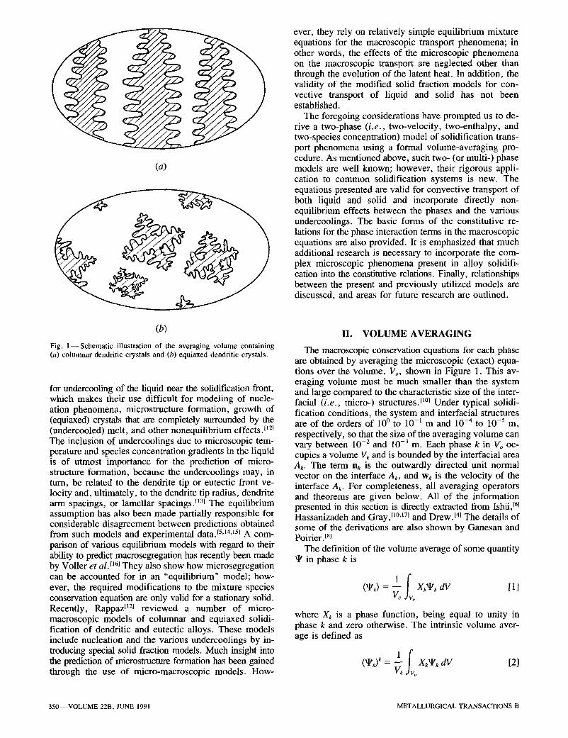
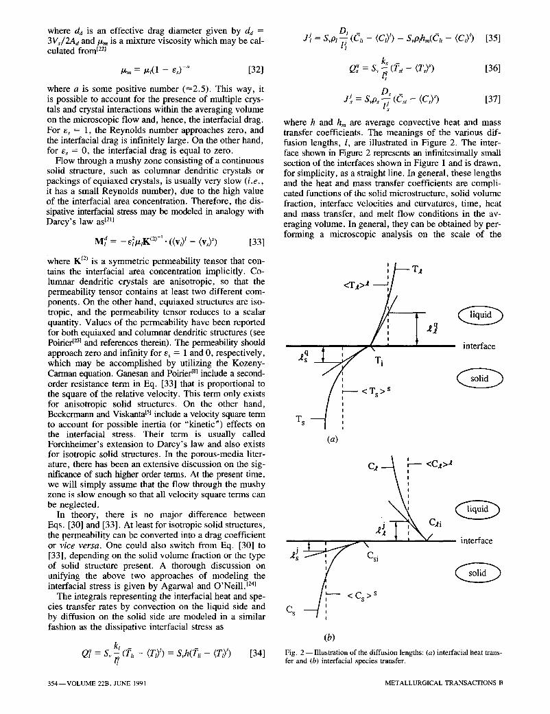
where h and h m are average convective heat and mass transfer coefficients. The meanings of the various dif- fusion lengths, l, are illustrated in Figure 2. The inter- face shown in Figure 2 represents an infinitesimally small section of the interfaces shown in Figure 1 and is drawn, for simplicity, as a straight line. In general, these lengths and the heat and mass transfer coefficients are compli- cated functions of the solid microstructure, solid volume fraction, interface velocities and curvatures, time, heat and mass transfer, and melt flow conditions in the av- eraging volume. In general, they can be obtained by per- forming a microscopic analysis on the scale of the
Ts
<T t>2 / /
Ts > s
(a)
T~
interface
C2 ~ <C2>2
2~ I i \ ~ interface
s > s
: cs [ i
(b) Fig. 2--I l lustrat ion of the diffusion lengths: (a) interfacial heat trans- fer and (b) interracial species transfer.
354--VOLUME 22B, JUNE 1991 METALLURGICAL TRANSACTIONS B

averaging volume. In fact, such analyses constitute the foundation of present theories of microstructure forma- tion during solidification of metal alloys. [131 Whereas much progress has been made in determining the length scales (and, thus, the interfacial heat and species fluxes) in diffusion-dominated growth, considerable additional re- search is needed to obtain the corresponding scales for convection-dominated solidification. It is beyond the scope of this paper to present any details of such microscopic models; only a few approaches are outlined in the following.
For small thermal or solutal Peclet numbers, the microscopic temperature or concentration profiles nor- mal to the interface can be assumed to be quasi-steady, t~3~ The profiles and, hence, the diffusion lengths in Eqs. [34] through [37] can then be determined from the solution of the steady diffusion equations for a given microscopic geometry. For example, for diffusion- dominated growth of a spherical crystal of radius R, in an infinite melt, I, and It are equal to Rs/5 (assuming a parabolic profile) and R~, respectively. Ohnaka t25j as- sumed a certain dendrite geometry and a parabolic spe- cies concentration profile in the solid to quite accurately model microsegregation. Another example of the utility of the above approach is given by the analysis of flow through porous media. Many of the expressions that have been derived for the permeability are based on capillary tube or slit models, with the velocity having a simple profile (see Poirier t231 for an application of such models to determine the permeability of mushy regions).
For flow in the liquid phase, particularly over moving equiaxed crystals and near the tip of dendrites, it is dif- ficult to specify realistic profiles in the liquid phase. In that case, it is of advantage to utilize empirical heat and mass transfer coefficients (see Eqs. [34] and [35]) that are calculated, in a similar fashion as the drag coeffi- cient, from suitable heat and mass transfer correlations. Such correlations have, for example, been measured by Hayakawa and Matsuoka t261 for settling crystals. A gen- eral discussion on convective heat and mass transfer cor- relations for dispersed solid/liquid flows is given by Agarwal. t27~ More experiments are needed to determine interfacial heat and mass transfer coefficients for the wide variety of solid structures present in solidifying metal alloys.
D. Topological Relation
The previous two sections show that the interfacial area concentration, Sv = Ai/Vo, is an important ingredient in the modeling of the interfacial transfer terms. From a physical point of view, the interfacial area concentration contains the information regarding the geometry of the interfaces that is lost through the averaging process. This information plays an important part in the behavior of a solidifying system and must be restored through a con- stitutive relation. As noted by Boure, t28~ the knowledge of the average motion of the interface alone does not suffice to determine the variation of the interfacial area concentration. This variation also depends on the ge- ometry (topology) of the interface.
The interfacial area concentration (as well as es) can be measured by quenching and sectioning the material
at a preselected time during the solidification process. The value Sv is then equal to twice the number of inter- sections of a random test line with the interface on a two- dimensional cross section per unit length of the test line.t291 Then, a mean characteristic length scale (radius) of the solid can be calculated from
3 e s /~s = - - [381
Sv
Much additional research is necessary before a general topological relation for Sv can be specified. In general, Sv is a function of the number of crystals per unit vol- ume, n, according t o [29]
Sv ~ n ~/3 [39]
The calculation of n is discussed in more detail in Section V-A. For columnar dendritic growth, n can be viewed as the number density of primary arms, so that n 1/3 ~ 1 / ) t I . The primary arm spacing, A~, may, in turn, be related to the local solidification conditions, t~31 Dur- ing solidification of a given averaging volume, Sv in- creases from zero, eventually reaches a maximum value, and then decreases again to zero because of merging of the solid/liquid interfaces and impingement. This be- havior may be modeled using the empirical relation given by Speich and Fisher: t3~
S ~ - es(1 - e~) [40]
This relation cannot be used for es < 0.02 and e~ > 0.95, because dSv/des should be infinitely large at e~ = 0 and 1. Furthermore, coarsening experiments at a constant solid fraction have shown that the interfacial area concentra- tion decreases according to t3~1
S~ ~ t a 1/3 [41]
where ta is the local "aging" time. At the present time, it is not clear how the above descriptions can be incor- porated into a single topological relation for a given metal alloy.
E. Modeling of the Macroscopic Shear Stresses and Heat and Species Fluxes
Constitutive relations for the macroscopic viscous stress (a'k), heat flux (q~), and species flux (Jk) are obtained under the following simplifying assumptions:
(1) The viscous stresses for both the solid and liquid phases are proportional to the rates of deformation. The role of the solid viscosity is discussed below. The con- tribution to the viscous stresses due to displacement gra- dients (arising from density differences and phase change) is negligibly small. (This assumption is often invoked in modeling of multiphase flows t4j but was not made ini- tially by Ganesan and Poirier). I81 (2) The heat and species fluxes are given by Fourier's and Fick's laws, respectively. (3) The fluctuating components of the viscosity, thermal conductivity, and species diffusion coefficient of phase k are negligibly small.
METALLURGICAL TRANSACTIONS B VOLUME 22B, JUNE 1991--355
Any of the above assumptions can be relaxed. The fol- lowing relations can now be written
('r~) = /x,(VVk + (VvD') [42]
(qk) = --kk" (VT,) [43]
(Jk) = - D , . pk(VCk) [44]
Using averaging theorems [9] and [10], the above equa- tions can be rewritten as
(~'~) = m/v(e,(v~>~) + [v(ek<v~)~)] ' L
ofA ofA } + vknk dA + nkvk dA [45] i i [ 1s ]
(~ ) = -kk" e~V(Tk) k + ~ Lnk dA [461 k
[ 's ] {j~} = --Dk'pk ekV(Ck) k + ~ dkn~ dA [471 k
First, the average shear stress, ('r,), will be modeled. For relatively small density differences between the phases and/or small phase change rates, the interfacial veloci- ties of the liquid and solid phases are approximately equal (Eq. [28]). Then, by using Eq. [29], we can substitute (vs) s for vk inside the integrals in Eq. [45]. Hence, in view of the averaging theorem given by Eq. [11], we can write the following model for (xk):
<'~k> =/~* {V(e~<v~) ~) + [V(ek<v,)~)] '
- (V)~Vek- Ve,(vy} [48]
A similar model has been proposed by Ishii. [6] The macroscopic or effective liquid viscosity, /z*, is often taken to be equal to the actual liquid viscosity3 s] In real- ity, /z* depends on el and the solid structure and might be zero even if the liquid is microscopically viscous (e.g., if the liquid is contained in small pockets). One can see that for a stationary solid phase (i.e., ( v y = 0), an expression for the liquid shear stress is obtained that is identical to the one usually employed in porous media- type flows, i.e., in terms of the gradients of the super- ficial liquid velocity, el(Vt)t. [9] In the other extreme, if the solid crystals move with the same velocity as the liquid phase, the last two terms in Eq. [48] can be com- bined with the first two terms on the right-hand side, so that the liquid shear stress is proportional to the gradients of the actual velocity, ( v J = (v) ~. For ( v J = (v) ~ and e~ ~ 1, Einstein's theory results in/x* -- 3.5/z~, [32] which is due to macroscopic momentum transfer through inter- actions between the solid crystals. The solid shear stress is always proportional to the actual solid velocity gra- dients, which can be seen by combining the terms in Eq. [48]. For equiaxed crystals, the effective solid vis- cosity increases with increasing solid volume fraction and crystal size because of stronger crystal interactions. For solid fractions greater than about 20 pct, the solid/liquid mixture can be viewed as a non-Newtonian slurry, with the viscosity depending on the crystal size and shape, the solid fraction, and the shear rate. [33] The exact nature of the corresponding relation for the effective solid vis-
cosity is not known at the present time. However, in analogy with Eq. [32], we may propose ( )es
tz~* = p.s(es = 0 ) 1 - - [ 4 9 1
where e~ is a critical solid volume fraction above which the equiaxed crystals merge to form a rigid solid struc- ture (e~ ~ 0.4 to 0.6). Alternatively, one could assume that the solid viscosity increases exponentially with es. t33] For e, > e~, as well as for columnar growth at any solid fraction,/~* is infinitely large (Section m - A ) . This forces the macroscopic velocity gradients in the solid to vanish. For example, if the rigid solid structure is attached to a wall, the solid velocity will then be uniformly equal to the velocity of the wall (which is usually zero), due to the no-slip condition.
The integrals in Eqs. [46] and [47] for the macrocopic heat and species fluxes are often called tortuosity vec- tors. [34'351 They may be modeled by introducing (stag- nant) effective thermal conductivities and mass diffusivities as
(q,) = - k * . ekV(Tk)* [50]
( J k) = - D*. pkekV(Ck)* [511
k* and D* should be obtained from measurements and depend on the interfacial structure. In general, the ma- terial coefficients k* and D* are different from their microscopic counterparts. For example, for small equiaxed crystals completely surrounded by the melt (and no col- lisions), the effective thermal conductivity and mass dif- fusivity of the solid are equal to zero, because no heat and species can be transferred through such a solid on a macroscopic scale. Despite the importance of these is- sues, very little research has been performed in this area. [36]
Finally, one needs to model the macroscopic disper- sive stresses and heat and species fluxes given in Table I. Traditionally, this has been accomplished through the use of increased viscosities, thermal conductivities, and mass diffusivities. For two-phase flows, this is an area of considerable research and controversy. Only models of limited validity are available, and it is not clear how the dispersive fluxes can be modeled for the wide variety of flow regimes present in the solid/liquid sys- tems considered here. Ganesan and Poirier ~81 argue that for a liquid fraction close to unity, the dispersive flux is insignificant when compared to the convective flux. This is, however, only true if the flow in the liquid is laminar. It is important to realize that the dispersive fluxes in the pure liquid region (el = 1) are nonzero if the flow is turbulent. For small values of the liquid fraction, the dis- persive momentum flux is negligibly small compared to the interfacial stress; however, this might not be true for the dispersive heat and species fluxes. At the present time, the dispersive fluxes will simply be retained un- modeled in the macroscopic equations.
IV. THERMODYNAMIC RELATIONS
A. Interfacial Temperatures and Concentrations
Under the assumption of thermodynamic equilibrium, the following conditions are valid at any point on the solid/liquid interface:
356- -VOLUME 22B, JUNE 1991 METALLURGICAL TRANSACTIONS B
Tti = T,, = Ti [52]
Cs, /Ct , = K(Ti) [53]
Cl i : g ( T i ) [54]
where Ti is the equilibrium temperature of the interface. The segregation coefficient K(Ti) and the equation of the liquidus line g(T~) can readily be obtained from equilib- rium phase diagrams. Many solidification processes de- viate from the above conditions. However, Eqs. [52] through [54] can be modified to account for kinetic, cur- vature, or pressure effects. [13.37]
The above local conditions need to be related to the average interfacial temperatures and concentrations for use in the interfacial balances. For this purpose, 7~kl and Ck~ will be regarded as simple (i.e., nonweighted) av- erages over the interfaces in the averaging volume. Then, we can write immediately
Tsi : Tli : T i [55]
However, Eqs. [53] and [54] hold on an average basis only if the temperature of the solid/liquid interface in the averaging volume is uniform (i.e., Ti = 7~ in Vo). This is usually a good approximation for dendritic and eutectic solidification structures. [13] However, for strongly varying interfacial curvatures and/or for highly direc- tional heat and species fluxes at the interface (which may be caused by convection), T~ will be nonuniform in the averaging volume. This problem can be overcome by linearizing the phase diagram, so that K is a constant and g(T~) is a linear function. Then,
C s i / C l i : K l [56]
Cti = gt(L) [57]
where the superscript l indicates that they are obtained from a linearized phase diagram. Note that Eqs. [55] through [57] are generally not valid for the volume- averaged temperatures and concentrations of the phases, (Tk) k and (Ck) k.
B. Enthalpies and Densities
Neglecting the influence of pressure, the local en- thalpy and density of phase k can be obtained from ap- propriate state functions, i.e.,
hk = hk(Tk, Ck) [58]
Pk = Pk(Tk, Ck) [59]
where Ck stands for the concentration of each species present. Again, the above local conditions need to be expressed in terms of average quantities for use in the macroscopic equations. Unless the microscopic temper- ature and concentration profiles in the averaging volume are known (e.g., if they are uniform), the state functions need to be linearized in both temperature and species concentration. Note that this is equivalent to introducing constant specific heats and coefficients of expansion. Then,
<hk) k = ~ X~k(Tk, Ck) dV = h~(<Tk> k, (Ck> k) [601 o
'L and also
Xkp,(Tk, Ck) dV = p~(<Tk) k, <Ck> k) [611
/~kg = h~(/~k~, Cki) [62]
fik~ = P~(7~ki, Cki) [631
where the superscript l indicates that these functions are linearized in all variables. Also note that the difference b_etwee_n the interfacial liquid and solid enthalpies, hli , - - hsi , but n o t (hi> l - (hs> s, i s equal to the latent heat of fusion, unless the temperatures and concentrations in both the liquid and solid are uniform.
V. DISCUSSION
A. Calculation of the Solid Fraction
The model equations presented in the previous sec- tions are valid for any volume fraction and reduce to the correct limits for a pure solid (e, = 1) and a pure liquid (es = 0). Therefore, they are suitable for one-domain numerical solution methodologies. For this purpose, it is instructive to briefly examine the calculation procedures for the solid volume fraction, es.
With Eqs. [24], [26], [27], and [34] through [37], the interfacial energy and species balances given in Table I can be written, respectively, as
kt - ks (L - <T~> s) [64] Ahpsff~,s = ~ (Ti - (TJ) +
(C l i - Csi)Psffns = ~ ( C l i - <Cl> l) d
p s D s + ----r- (Csi - <C) s) [651
where Ah = flli - ~lsi is the latent heat of fusion. Note that the terms in the parentheses on the right-hand side of Eqs. [64] and [65] are the thermal and constitutional undercoolings, respectively. The intrinsic volume- averaged temperatures and species concentrations (or enthalpies) are determined from the solution of the macroscopic conservation equations for each phase. Then, together with the phase diagram relations presented in the previous section, the above interfacial balances can be solved for the interfacial temperatures and species concentrations as well as for the average interfacial ve- locity, ~ns. The variation of the solid volume fraction can then be determined from the macroscopic solid con- tinuity equation (Table I), i.e.,
0 Ot (esps) + V. (e,ps<vY) = SvPs~ns [66]
The right-hand side of Eq. [66] accounts for the solid fraction variation due to phase change. It can be seen that during coarsening (when Sv decreases) at a constant solid fraction, the average velocity of the interface, ~,s, is equal to zero. The second term on the left-hand side of Eq. [66] accounts for the solid fraction variation due to advective transport of solid.
METALLURGICAL TRANSACTIONS B VOLUME 22B, JUNE 1991--357
The advection of the solid can be further illuminated by writing the solid fraction as G = nV~c, where V,c is the solid volume of a single crystal. Substitution into Eq. [66] yields after a few steps
On Sv - - + V - ( ( v ) ~ n ) = ~.~ ot
n [Op,V,~ + ivY" V(p,V,~)] =r~ [67] p~V~r L 3t
The left-hand side of Eq. [67] shows that the number density of crystals is conserved so that the right-hand side is equal to the net generation rate of crystals, n. The net generation rate includes both the "birth" and "death" of crystals due to nucleation, dendrite arm breakoff, ag- glomeration, and other effects. Whereas nucleation has received considerable research attention, t13,371 it is not clear how to model the other modes of crystal generation in the presence of convection. Equation [67] can, theoret- ically, be solved for the crystal density, n. Recall that n is an important ingredient in the topological relation for the interfacial area concentration, Sv (Section III-D).
Since there presently exist considerable uncertainties in the modeling of the interfacial transfer terms, special care must be taken in calculating the solid fraction. For limiting values of certain parameters in the interfacial transfer terms, the solid fraction should take the correct values corresponding, for example, to the cases of com- plete thermal equilibrium within Vo, complete chemical equilibrium (i.e., no species concentration gradients) in the liquid phase and no species diffusion in the solid (Scheil's model), or complete mixing of the species in both phases (lever rule). Fortunately, this can be achieved through proper numerical solution procedures, t381 Some of such limiting cases are examined in greater detail in the next section. The following discussion also illus- trates that considerable insight can be gained by utilizing the present equations as a starting point to arrive at sim- plified models.
B. Mixture Models
By adding up the macroscopic conservation equations for the solid and liquid phases and making use of the interfacial balances, we obtain the following mixture equations:
(Mass Conservation)
0 S
at (etp~ + e~p~) + V. (e,p~(v3 ~ + e,p~(v~) ) = 0 [68]
(Momentum Conservation)
O S
Ot (etpt(vt)t + esPs(Vs) )
+ V . (elpt(vt)l(vl) l + esPs(Vs)S(vs) s)
= - e , V ( p , ) ' - e s V ( p y
+ v - ~ ? {V(e,(v,>')
+ [V(el(Vl))l t - (vs)SVel- Vel(Vs) s}
+ V. t~*e,{V(vy + [V(vy]'}
+ etpt(b~)t + Gp~(bY
[69]
(Energy Conservation)
0 - (e,o,(h,) ~ + e s o A h Y ) Ot
+ V. (etpl(hz)l(vt) ' + e , p s ( h y ( v Y )
= V. (k*e,V(T~)') + V. (k*GV(T,)') [701
(Species Conservation)
a (elPl(Ct)l + esPs(Cs) s) Ot
+ V" (6lPl(Ct)l(Vl) l + esPs(Cs)S(Vs) s)
= 7 . (D*etp, V(C~) t) + 7 . (D*GpsV(C~) ~) [711
In the above equations, the dispersive fluxes are not in- cluded for simplicity. Mixture energy and species con- servation equations obtained in this manner were utilized by Beckermann and Viskanta. [5] Various mixture models were also derived by Hills et al. ,ill Prantil and Dawson, t2j and Bennon and Incropera TM without using a volume- averaging procedure. The above mixture equations are entirely general, since no additional assumption has been invoked. Usually, mixture variables are introduced to fa- cilitate a solution of the equations; however, the phase variables cannot be entirely eliminated (see Bennon and Incropera). TM The beauty of the mixture equations is that no interfacial transfer terms are present that would re- quire modeling and that they contain only macroscopic variables.
The main problem associated with the use of such mixture equations is that relationships between the macroscopic variables of each phase need to be known a priori, because the mixture equations contain too many unknowns. First, basic thermodynamic and phase dia- gram relations are generally not valid for the macro- scopic (averaged) variables, as mentioned in Section IV. For example, even the linearized phase diagram rela- tionships (Eqs. [56] and [57]) cannot be used to relate the average liquid and solid species concentrations, (CY and (Cy , unless the concentrations are uniform in the averaging volume. For the same reason, (hY - ( h y is generally not equal to the latent heat of fusion. Alter- native thermodynamic relations between the volume- averaged species concentrations and enthalpies would always be of a highly empirical nature. Similarly, it is not possible to determine both the liquid and solid ve- locities using the mixture momentum equation only. Therefore, one has to assume that the solid is stationary or postulate some ad hoc relationship between the liquid and solid velocities. In addition, the gradients of the volume-averaged pressures of each phase must be as- sumed to be equal. Bennon and Incropera TM introduced a term into the mixture momentum equation that ac- counts for the interfacial friction due to the relative ve- locity between the solid and liquid. Beckermann and Viskanta t51 utilized the momentum equation for the liq- uid only and assumed the solid velocity to be equal to
358--VOLUME 22B, JUNE 1991 METALLURGICAL TRANSACTIONS B
zero. This strategy was also adopted by Nandapurkar et a l . [391 and Ganesan and Poirier. [8] Voller et al.,[16] o n
the other hand, utilized the mixture momentum equation and assumed that ( v f = (v,) ~ in one of their numerical simulations. Flood et al. t4~ introduced a consolidation factor that varies with the solid fraction in order to spec- ify the relationship between the solid and liquid veloc- ities in the mixture momentum equation.
For the mixture energy and species conservation equations, the problem of having to specify relationships between the volume-averaged enthalpies and species concentrations of each phase can be overcome by mak- ing certain assumptions about the interfacial transfers. For "perfect" interfacial heat and species transfer, the solid and liquid in the averaging volume are in complete thermal and chemical equilibrium. This can be expressed a s
( T f = (L) ~ = 7~ [72]
(Cl) l = fill [73]
( C y = Cs, [74]
In other words, the liquid and solid phases in an av- eraging volume are well mixed. The above assumptions were invoked, for example, by Bennon and Incropera t31 and Beckermann and Viskanta. tS] With Eqs. [55] through [57], the solid fraction can be calculated directly from the lever rule.
The validity of the above equilibrium assumptions can be established by examining the interfacial energy and species balances (Eqs. [64] and [65]), respectively. It can be seen that the volume-averaged temperatures and species concentrations of each phase approach their interracial counterparts if (1) the interfacial velocity, ~,~, ( i .e . , the solidification rate) is very low, (2) the diffusion lengths, l, are very small or the heat and mass transfer coefficients are very large, (3) the thermal conductivities and mass diffusivities are very large, or (4) the segre- gation coefficient, K, is very close to unity and the latent heat of fusion is very small.
The assumption of thermal equilibrium within Vo is much more likely to be adequate than the chemical equi- librium assumption, because for metal alloys, the ratio of the thermal to the mass diffusivities ( i .e . , the Lewis number) is typically greater than 104 . This conforms with the well-known fact that solidification on a microscopic scale is mainly controlled by species concentration gra- dients, tl31 The assumption of thermal equilibrium rep- resents, however, a conceptual problem in modeling of nucleation and growth of equiaxed crystals in an under- cooled melt. Whereas the assumption of a well-mixed liquid within the averaging volume is usually valid for the interdendritic region, deviations from equilibrium are likely to occur in the dendrite tip region and for a eu- tectic growth front, because the diffusion lengths in the liquid are much larger. Although in conventional solid- ification processes the region of incomplete mixing in the liquid is limited to a small region near the eutectic front or the dendrite tips, it is crucial to consider this phenomenon in modeling of microstructure formation. I121
The most suspect assumption in the equilibrium model is, however, Eq. [74], because the diffusion coefficient
in the solid, D~, is typically very small. Consequently, there are significant species concentration variations in the solid within the averaging volume, which are usually referred to as microsegregation. It is instructive to con- sider the limiting case of no species diffusion in the solid, i.e., Ds = 0. In that case, the macroscopic species con- servation equation for the solid phase (Table I) becomes (neglecting dispersion)
0 s s s (e,p,(C,) ) + v . (e,p,(C,) (v,)) = ~ r ~
= Cs~ (e~p~) + v . (e~p~(v~ [75]
The above equation allows for the calculation of (Cs) s and, hence, macrosegregation from the knowledge of C~i (or the interfacial temperature, lri) throughout the solid- ification process, even in the presence of solid move- ment. Assuming ( v y = 0, the above equation was also derived by Voller et al. tl61 and Rappaz and Voller t411 using a different procedure. With the additional assumptions of (Vs) s = ~Vl) l = O, (C1) l = Cti and D* = 0, the sum of Eq. [75] and the macroscopic liquid species conservation equation (Table I) reduces to the differential form of Scheil's equation. Equation [75] can be substituted into the mixture species conservation (Eq. [71]) to obtain a mixture model that accounts for microsegregation. Such a mixture model with (vs) ~ = 0 was examined numeri- cally by Voller e t a / . [161
VI. CONCLUSIONS
A two-phase model of transport phenomena during so- lidification is developed utilizing the technique of vol- ume averaging. The model accounts directly for the effects of the microscopic (nonequilibrium) processes on the macroscopic transport phenomena. It is shown that solid and liquid convection, nucleation, undercoolings due to incomplete mixing within the phases on a microscopic scale, and the effects of different solid structures can be incorporated into the model in a consistent manner. This will ultimately allow for the simultaneous prediction of the structure and composition of a solidified material on microscopic and macroscopic scales. Although the basic forms of the various constitutive relations are outlined, considerable additional work is needed to obtain suitable descriptions of the microscopic phenomena on which they are based. In this respect, modeling of the interfacial area concentration, the diffusion lengths and/or drag, heat and mass transfer coefficients, and the macroscopic material coefficients should definitely receive more research attention.
Significant advances have recently been made in cou- pling microscopic models to the macroscopic (mixture) heat flow equation. I12,42,431 This paper highlights a number of other issues that should be addressed in micro-macroscopic modeling. Additional insight can be gained by incorporating microscopic models into the present two-phase model instead of into traditional mixture equations. Efforts are currently underway to compare the volume-averaged two-phase and available
METALLURGICAL TRANSACTIONS B VOLUME 22B, JUNE 1991--359

micro-macroscopic models [121 for diffusion- dominated solidification.
Finally, it should be mentioned that it is relatively straightforward to extend the present model to more than two phases, to account for the presence of a gas phase or additional solid and liquid phases. This may, for ex- ample, be important in the modeling of solid-state tran- sitions, porosity formation, mold filling, and casting of composite materials.
a
A b Co C
d D
g h hk hm I J J
k K (2)
1 Mi
M
h nk
p q a
Re r & t T v V W F
Ek
K
A~
P or
'lr
NOMENCLATURE
positive number (Eq. [32]) area body force per unit volume drag coefficient concentration of a chemical species, i.e., mass fraction length scale coefficient of diffusion tensor of a species in the multicomponent mixture equation of liquidus line (Eq. [54]) average convective heat transfer coefficient specific enthalpy of phase k average convective mass transfer coefficient unit tensor species flux total interfacial species transfer rate per unit volume thermal conductivity tensor second-order permeability tensor diffusion length interfacial momentum source due to surface tension total interfacial momentum transfer rate per unit volume net generation rate of crystals outwardly directed unit normal vector on the interface of phase k pressure heat flux total interracial heat transfer rate per unit volume Reynolds number, (as defined by Eq. [31]) radius interracial area concentration time temperature velocity volume velocity of the interface interfacial mass transfer rate due to phase change volume fraction of phase k mean curvature of the solid-liquid interface segregation coefficient primary arm spacing kinematic viscosity mass average density surface tension shear stress a quantity of phase k
Xr phase function ~k a quantity of phase k
Subscripts
a aging c crystal d projected or drag i interfacial k phase k 1 liquid m mixture n normal s solid o averaging
Superscripts
c critical d dissipative j species transfer rate l linearized q heat transfer rate t dispersive flux or transpose of a tensor F due to phase change z momentum transfer rate
fluctuating component - interfacial average * effective
A C K N O W L E D G M E N T S
The work reported in this paper was supported by the National Science Foundation under Grant Nos. CBT-8808888 and CTS-8957149 and by the ALCOA Technical Center, Alcoa Center, PA. The authors thank the reviewers for their helpful suggestions.
REFERENCES
1. R.N. Hills, D.E. Loper, and P.H. Roberts: Q. J. Mech. Appl. Mathematics, 1983, vol. 36, pp. 505-36.
2. V.C. Prantil and P.R. Dawson: Transport Phenomena in Mate- rials Processing, ASME, New York, NY, 1983, pp. 469-84.
3. W.D. Bennon and F.P. Incropera: Int. J. Heat Mass Transfer, 1987, vol. 30, pp. 2161-70.
4. D.A. Drew: Ann. Rev. Fluid Mech., 1983, vol. 15, pp. 261-91. 5. C. Beckermann and R. Viskanta: PhysicoChem. Hydrodyn., 1988,
vol. 10, pp. 195-213. 6. M. Ishii: Thermo-Fluid Dynamic Theory of Two-Phase Flow,
Eyrolles, Paris, 1975. 7. W.G. Gray: Adv. Water Resour., 1983, vol. 6, pp. 130-40. 8. S. Ganesan and D.R. Poirier: Metall. Trans. B, 1990, vol. 21B,
pp. 173-81. 9. W.G. Gray and K. O'Neill: Water Resour. Res., 1976, vol. 12,
pp. 148-54. 10. M. Hassanizadeh and W.G. Gray: Adv. Water Resour., 1979,
vol. 2, pp. 131-41. l l. R. Viskanta and C. Beckermann: Interdisciplinary Issues in
Materials Processing and Manufacturing, ASME, New York, NY, 1987, vol. 2, pp. 501-26.
12. M. Rappaz: Int. Mater. Rev., 1989, vol. 34, pp. 93-123. 13. W. Kurz and D.J. Fisher: Fundamentals of Solidification, Trans
Tech Publications, Ltd., Aedermannsdorf, Switzerland, 1989. 14. M.S. Christenson, W.D. Bennon, and F.P. lncropera: Int. J. Heat
Mass Transfer, 1989, vol. 32, pp. 69-79. 15. W.D. Bennon and F.P. Incropera: ASMEJ. Heat Transfer, 1989,
vol. 111, pp. 706-12.
360--VOLUME 22B, JUNE 1991 METALLURGICAL TRANSACTIONS B

16. V.R. Voller, A.D. Brent, and C. Prakash: Int. J. Heat Mass Transfer, 1989, vol. 32, pp. 1719-31.
17. M. Hassanizadeh and W.G. Gray: Adv. Water Resour., 1979, vol. 2, pp. 191-203.
18. S. Whitaker: AIChE J., 1967, vol. 13, pp. 420-27. 19. J.C. Slattery: AIChE J., 1967, vol. 13, pp. 1066-71. 20. W.T. Sha, B.T. Chao, and S.L. Soo: Nucl. Eng. Des., 1984,
vol. 82, pp. 93-106. 21. M. Hassanizadeh and W.G. Gray: Adv. Water Resour., 1980,
vol. 3, pp. 25-40. 22. M. Ishii and N. Zuber: A/ChE J. , 1979, vol. 25, pp. 843-55. 23. D.R. Poirier: Metall. Trans. B, 1987, vol. 18B, pp. 245-56. 24. P. Agarwal and B. O'Neill: Chem. Eng. Sci., 1988, vol. 43,
pp. 2487-99. 25. I. Ohnaka: Trans. Iron Steel Inst. Jpn., 1986, vol. 26, p. 1051. 26. T. Hayakawa and M. Matsuoka: Heat Transfer--Jpn. Res., 1973,
vol. 2, pp. 104-15. 27. P. Agarwal: Chem. Eng. Sci., 1988, vol. 43, pp. 2501-10. 28. J.A. Boure: Multiphase Science and Technology, Hemisphere
Publishing Corp., 1987, vol. 3, pp. 3-30. 29. R.T. DeHoff and F.N. Rhines: Quantitative Microscopy, McGraw-
Hill Book Co., New York, NY, 1968. 30. G.R. Speich and R.M. Fisher: Recrystallization, Grain Growth
and Textures, ASM, Metals Park, OH, 1966, pp. 563-98. 31. S.P. Marsh, M.E. Glicksman, L. Meloro, and K. Tsutsumi:
Modeling and Control of Casting and Welding Processes IV, TMS, Warrendale, PA, 1988, pp. 15-23.
32. J.W. Nunziato: Theory of Dispersed Multiphase Flow, Academic Press, New York, NY, 1983, pp. 191-226.
33. V. Laxmanan and M.C. Flemings: Metall. Trans. A, vol. l lA , 1980, pp. 1927-37.
34. S. Whitaker: Chem. Eng. Sci., 1973, vol. 28, pp. 139-47. 35. W.G. Gray: Chem. Eng. Sci., 1975, vol. 30, pp. 229-33. 36. S.L. Soo: Particulates and Continuum, Hemisphere Publishing
Corp., New York, NY, 1989. 37. M.C. Flemings: Solidification Processing, McGraw-Hill Book Co.,
New York, NY, 1974. 38. D.B. Spalding: Numerical Properties and Methodologies in Heat
Transfer, Hemisphere Publishing Corp., Washington, DC, 1983. 39. P. Nandapurkar, D.R. Poirier, J.C. Heinrich, and S. Felicelli:
Metall. Trans. B, 1989, vol. 20B, pp. 711-21. 40. S.C. Flood, L. Katgerman, A.H. Langille, S. Rogers, and C.M.
Read: Light Metal 1989, AIME, Warrendale, PA, 1988, pp. 943-47.
41. M. Rappaz and V. Voller: Metall. Trans. B, 1990, vol. 21B, pp. 749-53.
42. J.L. Desbiolles, Ph. Thevoz, and M. Rappaz: Modeling and Con- trol of Casting and Welding Processes IV, TMS, Warrendale, PA, 1988, pp. 625-34.
43. C.S. Kanetkar and D.M. Stefanescu: Modeling and Control of Casting and Welding Processes/V, TMS, Warrendale, PA, 1988, pp. 697-708.
METALLURGICAL TRANSACTIONS B VOLUME 22B, JUNE 1991--361