A Versatile Rocket Engine Hot Gas Facility - NASA · A Versatile Rocket Engine Hot Gas Facility...
9
• NASA Contractor Report 195339 A Versatile Rocket Engine Hot Gas Facility NASA-CR-195339 19940029625 James M. Green NYMA, Inc. Engineering Services Division Brook Park, Ohio ." I > June 199" Prepared for Lewis Research Center Under Contract NAS3-25266 National Aeronautics and Space Administration https://ntrs.nasa.gov/search.jsp?R=19940029625 2018-08-27T22:50:02+00:00Z
Transcript of A Versatile Rocket Engine Hot Gas Facility - NASA · A Versatile Rocket Engine Hot Gas Facility...
•
NASA Contractor Report 195339
A Versatile Rocket Engine Hot Gas Facility
NASA-CR-19533919940029625
James M. GreenNYMA, Inc.Engineering Services DivisionBrook Park, Ohio
."
I>
June 199"
Prepared forLewis Research CenterUnder Contract NAS3-25266
National Aeronautics andSpace Administration
https://ntrs.nasa.gov/search.jsp?R=19940029625 2018-08-27T22:50:02+00:00Z
A Versatile Rocket Engine Hot Gas Facility
James M. GreenNYMA,Inc.
Engineering Services DivisionBrook Park, Ohio 44142
1111111111111111111~ilillf~~lrtll~iijiff~11111111111111111131176014115332
ABSTRACT
The capabilities of a versatile rocket engine facility,located in the RocketLaboratory at the NASALewis ResearchCenter, are presented. The gaseous hydrogen/oxygen facilitycan be used for thermal shock and hot gas testing of materialsand structures as well as rocket propulsion testing. Testingover a wide range of operating conditions in both fuel andoxygenrich regimes canbeconducted, with cooledoruncooledtest specimens. The size and location of the test cell providethe ability to conduct large amounts of testing in short timeperiods with rapid turnaround between programs.
INTRODUCTION
The Rocket Laboratory at the NASA Lewis ResearchCenter consists ofa numberofsmall test facilities designedforrocket propulsion and related research. The small size andworkhorse nature of the facilities in the Rocket Lab, plus theexcellent technical support crew, team up to provide high dataoutput at low cost, with rapid turnaround times betweenprograms. Some of the other facilities in the Rocket Lab aredescribed in Refs. 1 to 4.
Test Cell 22 of the Rocket Laboratory (RL22), alsoknown as the Hot Gas Facility or Thermal Shock Test Rig, isa versatile facility capable of supporting many different typesof research programs.
The gaseous hydrogen/oxygen (Ri02) rocket combustor in the test facility is used to generate high temperature, highheat flux, H2 or 02 rich hot gas environments over a widerange ofoperating conditions and test times. Gas temperaturesfrom approximately 1000to 3000 °C (1832 to 5432 OF) can bedelivered, with heat flux at the nozzle exit as high as 5000 W/cm2 (4406 BTU/fi2s). Test specimens are generally mountedin the exhaust plane of the engine and subjected to the hightemperature gas.
1
RL22 has supported a diverse group of materials andstructures projects, working with in-house researchers as wellas outside industry. For example, two programs supportingEarth-to-orbit technology development have been tested inRL22. Ceramic Matrix Composite (CMC) materials testing isan ongoing program to verify the thermal shock durability andcoating performance of different CMC coupons and turbineblades.5 Thin Film Thermocouples (TFTC) were tested todevelop successful bonding techniques to adhere the TFTCmaterial to an alloy in a hot gas, erosive environment.6
Testing was also conducted in the area of hypersonicstructures research for the National Aerospace Plane (NASP)program, in the areas of seals and leading edges? Transpiration cooled seals, cooled with chilled~ gas, were tested todetermine cooling efficiency and improve the manufacturingtechniques of the seals. Leading edge coatings and structureswere tested in both H2 and 02 rich environments to determinethe performance ofthe leading edge coating and the structuraldesign.
While RL22 has mainly been utilized for materials andstructures testing, different hardware can also be mounted onthe test stand for conducting rocket propulsion research.
This paper will present an overview of the facility, thecapabilities of the mechanical and electronic systems, and adescription of the hardware used for many of the researchprograms in the facility.
FACILITY OVERVIEW
An aerial view ofthe RocketLab, shown in Fig. 1, showsthe location of RL22, along with the H2 and 02 tube trailersand the exhaust system for the cell. The propellant trailers arelocated behind earthen mounds, and are shared with theadjacent facility, RL21. Only one ofthe facilities can run at atime, but the two are routinely operated on an every-other-daybasis. The exhaust system was originally built to scrub hazard-
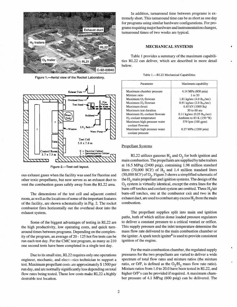
Figure 1.-Aerial view of the Rocket Laboratory.
ExhaUlI Tube-U
Figure 2.-Test cell layout.
ous exhaust gases when the facility was used for fluorine andother toxic propellants, but now serves as an exhaust duct tovent the combustion gases safely away from the RL22 area.
The dimensions of the test cell and adjacent controlroom, as well as the locations ofsome ofthe important featuresof the facility, are shown schematically in Fig. 2. The rocketcombustor fires horizontally out the overhead door into theexhaust system.
Some of the biggest advantages of testing in RL22 arethe high productivity, low operating costs, and quick turnaround times between programs. Depending on the complexity of the program, an average of20 - 125 hot fire tests can berun each test day. For the CMC test program, as many as 210one second tests have been completed in a single test day.
Due to its small size, RL22 requires only one operationsengineer, mechanic, and electronics technician to support atest. Maximum propellant costs are approximately $ 1500 perrun day, and are normally significantly less depending on totalflow rates being tested. These low costs make RL22 a highlydesirable test location.
2
In addition, turnaround time between programs is extremely short. This turnaround time can be as short as one dayfor programs using similar hardware configurations. For programs requiring major hardware and instrumentation changes,turnaround times of two weeks are typical.
MECHANICAL SYSTEMS
Table 1 provides a summary of the maximum capabilities RL22 can deliver, which are described in more detailbelow.
Table I.-RLZZ Mechanical Capabilities
Parameter Maximum capability
Maximum chamber pressure 4.14 MPa (600 psia)Mixture ratio 1 to ZOMaximum Oz flowrate 1.81 kg/sec (4.0 Ibm/sec)Maximum Hz flowrate 0.91 kg/sec (Z.O Ibm/sec)Maximum thrust 4.45 kN (1000 Ibr)Maximum test duration 30 to 60 secMaximum Hz coolant flowrate 0.11 kg/sec (0.Z5 Ibm/sec)Hz coolant temperature Ambient to 83 K (150 OR)Maximum high pressure water 379 Ipm (100 gpm)
coolant flowrateMaximum high pressure water 8.Z7 MPa (IZ00 psia)
coolant pressure
Propellant Systems
RL22 utilizes gaseous Hz and 0z for both ignition andmain combustion. The propellants are supplied by tube trailersat 16.5 MPag (2400 psig), containing 1.98 million standardliters (70,000 SCF) of Hz and 1.4 million standard liters(50,000 SCF) of Oz. Figure 3 shows a simplified schematic ofthe Hz main propellant and ignition systems. The design of the0z system is virtually identical, except the extra lines for thebum-off torches and coolant system are omitted. Three Hz/airbum-off torches, one at the combustor exit and two in theexhaust duct, are used to combust any excess Hz from the maincombustion.
The propellant supplies split into main and ignitionpaths, both of which utilize dome loaded pressure regulatorsto deliver a constant pressure to a critical venturi or orifice.This supply pressure and the inlet temperature determine themass flow rate delivered to the main combustion chamber orthe igniter. A spark torch igniterS is used to provide consistentignition of the engine.
For the main combustion chamber, the regulated supplypressures for the two propellants are varied to deliver a widespectrum of total flow rates and mixture ratios (the mixtureratio, or OfF, is defined as the OzlHz mass flow rate ratio).Mixture ratios from 1.0 to 20.0 have been tested in RL22, andhigher OfF's can be provided if required. A maximum chamber pressure of 4.1 MPag (600 psig) can be delivered. The

PropellllIllManifold
To Igniter
8_ p l/1 Cbeck ValveI)*::] ~';or ~ Sonic VcnrutI
~,I' SonicO~
AuIoalatiVah~ C klicf Val""
Purge
Fire Valve
Purge
h--.....C~ t------.--- Venl
To Burn-Off Torchesand Coolant System
Purge
From Trailer
Figure 3.-Simplified hydrogen system schematic.
maximum mass flow rates which can be delivered are 0.91 kg/sec (2.0 Ibn/sec) ofH2 and 1.81 kg/sec (4.0 Ibm/sec) of02. Themaximum test durations listed in Table 1 are dependent on thehardware and operating conditions being tested. Testing withmass flow rates lower than those typically used with existingRL22 hardware could provide longer run durations than thoselisted.
ing valves, driving the high pressure water system, and cooling test specimens.
The GN2 is obtained from a central Rocket Lab sourceat approximately 15.5 MPag (2250 psig), and is supplied to thepurges and components at different regulated pressures depending on the application. The panels of components used toroute the GN2 throughout RL22 are shown in Fig. 4.
Hydrogen Coolant System
The H2 coolant system is used to cool test specimensduring testing. H2 coolant is chilled to temperatures as low as83 K (150 OR) by passing the coolant through coils submergedin a liquid nitrogen bath. Maximum pressures of 10.34 MPag(1500 psig) can be delivered to the test specimen, at a maximum flow rate of0.11 kg/sec (0.25 Ibm/sec). Depending on thetest conditions, the low coolant supply temperature can bemaintained for as long as ten seconds before it begins increasing. The coolant system can be reconfigured in different waysto provide the flow parameters needed by the hardware to betested. Nitrogen gas (GN2) can also be supplied as a coolantusing this system.
Purge and Water Coolant Systems
Inert gas purges and water cooling systems are used toprovide smooth and safe operation of the rocket engine. GN2is used extensively throughout the test cell for a number ofpurposes, including purging lines; loading regulators, actuat-
Two separate water cooling systems are used to keep theengine and test specimen holders cooled during testing. Thefirst is a low pressure system, consisting of a single pump usedto cool the igniter and chamber spoolpiece of the engine. This
Figure 4.-Nitrogen supply panels.
3
Tank Fill
~l-"::l Chock Valve
P.....ureReeuLalOf []] Flow Meter
ZS; Bunol Diocl:a Automatic .::r:.I)(jValve ~ Hand Valve
r---"'" Vent
GN2 Supply
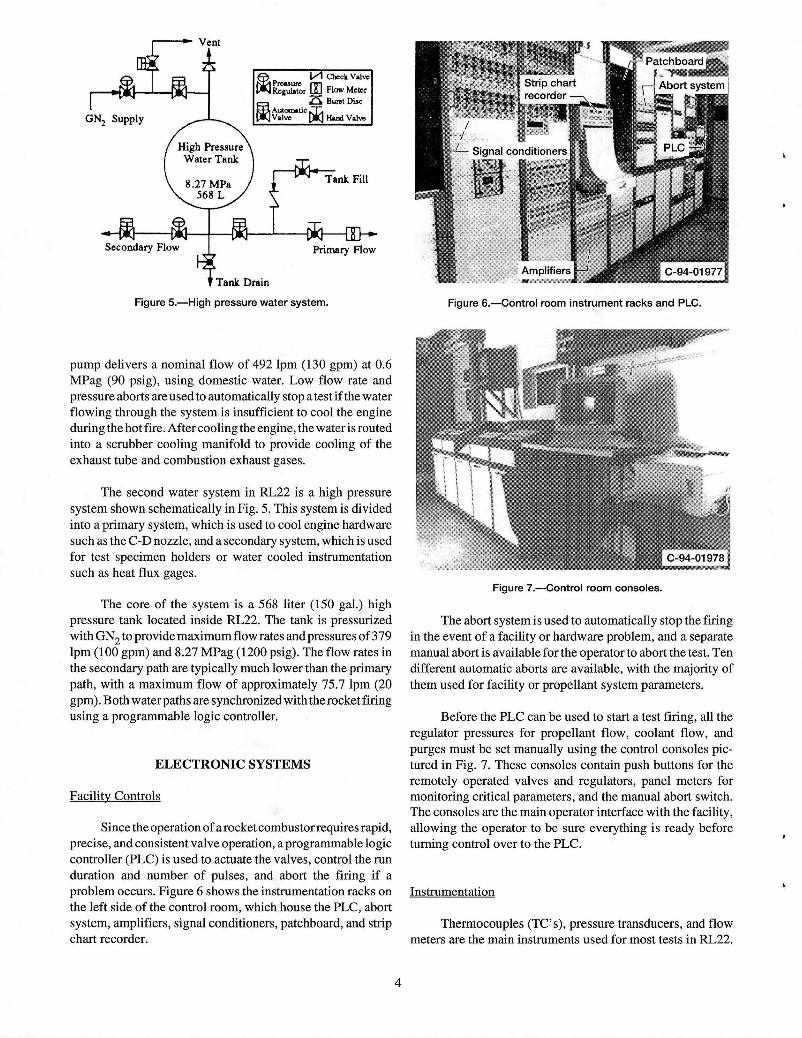
Figure 5.-High pressure water system. Figure 6.-Control room instrument racks and PLC.
pump delivers a nominal flow of 492 lpm (130 gpm) at 0.6MPag (90 psig), using domestic water. Low flow rate andpressure aborts are used to automatically stop a test ifthe waterflowing through the system is insufficient to cool the engineduring the hot fire. After cooling the engine, the water is routedinto a scrubber cooling manifold to provide cooling of theexhaust tube and combustion exhaust gases.
The second water system in RL22 is a high pressuresystem shown schematically in Fig. 5. This system is dividedinto a primary system, which is used to cool engine hardwaresuch as the C-D nozzle, and a secondary system, which is usedfor test specimen holders or water cooled instrumentationsuch as heat flux gages.
Figure 7.-Control room consoles.
The core of the system is a 568 liter (150 gal.) highpressure tank located inside RL22. The tank is pressurizedwith GN2 to provide maximum flow rates and pressures of379lpm (100 gpm) and 8.27 MPag (1200 psig). The flow rates inthe secondary path are typically much lower than the primarypath, with a maximum flow of approximately 75.7 lpm (20gpm). Both waterpaths are synchronized with the rocket firingusing a programmable logic controller.
ELECTRONIC SYSTEMS
Facility Controls
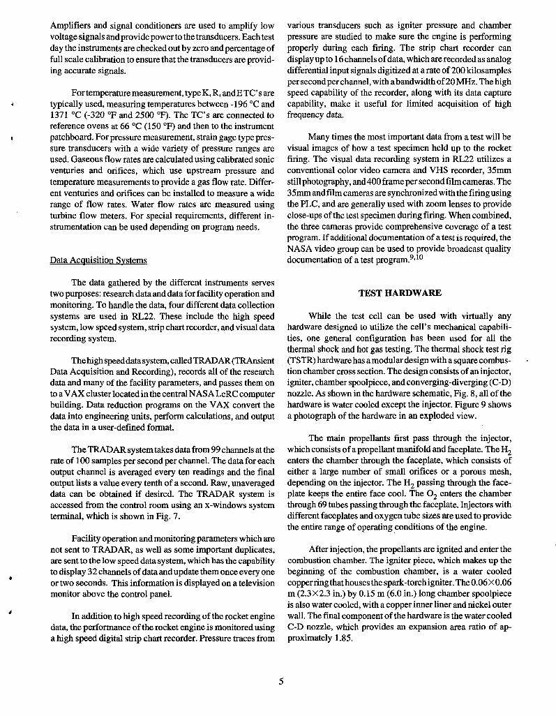
Since the operation ofa rocket combustor requires rapid,precise, and consistent valve operation, a programmable logiccontroller (PLC) is used to actuate the valves, control the runduration and number of pulses, and abort the firing if aproblem occurs. Figure 6 shows the instrumentation racks onthe left side of the control room, which house the PLC, abortsystem, amplifiers, signal conditioners, patchboard, and stripchart recorder.
The abort system is used to automatically stop the firingin the event of a facility or hardware problem, and a separatemanual abort is available for the operator to abort the test. Tendifferent automatic aborts are available, with the majority ofthem used for facility or propellant system parameters.
Before the PLC can be used to start a test firing, all theregulator pressures for propellant flow, coolant flow, andpurges must be set manually using the control consoles pictured in Fig. 7. These consoles contain push buttons for theremotely operated valves and regulators, panel meters formonitoring critical parameters, and the manual abort switch.The consoles are the main operator interface with the facility,allowing the operator to be sure everything is ready beforeturning control over to the PLC.
Instrumentation
Thermocouples (TC's), pressure transducers, and flowmeters are the main instruments used for most tests in RL22.
4
Amplifiers and signal conditioners are used to amplify lowvoltage signals andprovidepower to the transducers. Eachtestday the instruments are checked out by zero and percentage offull scale calibration to ensure that the transducers are providing accurate signals.
For temperature measurement, type K, R, andE TC' s aretypically used, measuring temperatures between -196°C and1371 °C (-320 of and 2500 OF). The TC's are connected toreference ovens at 66°C (150 OF) and then to the instrumentpatchboard. For pressure measurement, strain gage type pressure transducers with a wide variety of pressure ranges areused. Gaseous flow rates are calculated using calibrated sonicventuries and orifices, which use upstream pressure andtemperature measurements to provide a gas flow rate. Different venturies and orifices can be installed to measure a widerange of flow rates. Water flow rates are measured usingturbine flow meters. For special requirements, different instrumentation can be used depending on program needs.
Data Acquisition Systems
The data gathered by the different instruments servestwo purposes: research data and data for facility operation andmonitoring. To handle the data, four different data collectionsystems are used in RL22. These include the high speedsystem, low speed system, strip chart recorder, and visual datarecording system.
Thehigh speeddatasystem, calledTRADAR (TRAnsientData Acquisition and Recording), records all of the researchdata and many of the facility parameters, and passes them onto a VAX cluster located in the central NASA LeRC computerbuilding. Data reduction programs on the VAX convert thedata into engineering units, perform calculations, and outputthe data in a user-defined format.
The TRADAR systemtakes data from 99 channels at therate of 100 samples per second per channel. The data for eachoutput channel is averaged every ten readings and the finaloutput lists a value every tenth of a second. Raw, unaverageddata can be obtained if desired. The TRADAR system isaccessed from the control room using an x-windows systemterminal, which is shown in Fig. 7.
Facility operation and monitoring parameters which arenot sent to TRADAR, as well as some important duplicates,are sent to the low speed data system, which has the capabilityto display 32 channels ofdata andupdate them once every oneor two seconds. This information is displayed on a televisionmonitor above the control panel.
In addition to high speed recording of the rocket enginedata, the performance of the rocket engine is monitored usinga high speed digital strip chart recorder. Pressure traces from
5
various transducers such as igniter pressure and chamberpressure are studied to make sure the engine is performingproperly during each firing. The strip chart recorder candisplay up to 16 channels ofdata, which are recorded as analogdifferential input signals digitized at a rate of200 kilosamplesper secondperchannel, with abandwidth of20 MHz. The highspeed capability of the recorder, along with its data capturecapability, make it useful for limited acquisition of highfrequency data.
Many times the most important data from a test will bevisual images of how a test specimen held up to the rocketfiring. The visual data recording system in RL22 utilizes aconventional color video camera and VHS recorder, 35mmstill photography, and400 frame per second film cameras. The35mm and film cameras are synchronizedwith the firing usingthe PLC, and are generally used with zoom lenses to provideclose-ups ofthe test specimen during firing. When combined,the three cameras provide comprehensive coverage of a testprogram. If additional documentation of a test is required, theNASA video group can be used to provide broadcast qualitydocumentation of a test program.9,l0
TEST HARDWARE
While the test cell can be used with virtually anyhardware designed to utilize the cell's mechanical capabilities, one general configuration has been used for all thethermal shock and hot gas testing. The thermal shock test rig(TSTR) hardware has a modular design with a square combustion chamber cross section. The design consists of an injector,igniter, chamber spoolpiece, and converging-diverging (C-D)nozzle. As shown in the hardware schematic, Fig. 8, all of thehardware is water cooled except the injector. Figure 9 showsa photograph of the hardware in an exploded view.
The main propellants first pass through the injector,which consists ofa propellant manifold and faceplate. The Hzenters the chamber through the faceplate, which consists ofeither a large number of small orifices or a porous mesh,depending on the injector. The Hz passing through the faceplate keeps the entire face cool. The 0z enters the chamberthrough 69 tubes passing through the faceplate. Injectors withdifferent faceplates and oxygen tube sizes are used to providethe entire range of operating conditions of the engine.
After injection, the propellants are ignited and enter thecombustion chamber. The igniter piece, which makes up thebeginning of the combustion chamber, is a water cooledcopperring thathouses the spark-torchigniter. The 0.06 X0.06m (2.3X2.3 in.) by 0.15 m (6.0 in.) long chamber spoolpieceis also water cooled, with a copper inner liner and nickel outerwall. The final component ofthe hardware is the water cooledC-D nozzle, which provides an expansion area ratio of approximately 1.85.

IgniterH2/~ Ilnlet +
Injector
Water In
+Water Out
tW~rln
•
Figure B.-Schematic of thermal shock test hardware.
and operating costs associated with the facility, make RL22 anextremely attractive test location.
ACKNOWLEDGMENTS
This work was performed at the NASA Lewis ResearchCenter under Contract NAS3-21786. The author would like tothank Matt Melis, Andy Eckel, Fred Calfo, Paul Molnar, BillFurfaro, and the outstanding crew at the Rocket Lab who aretoo numerous to mention.
C-D nozzle
Figure 9.-Thermal shock test hardware.
REFERENCES
In addition to the engine hardware, sample holders areused to hold test specimens in the rocket exhaust. These aretypically constructed separately for each research program,but existing holders can be used for samples similar to thosepreviously tested, such as flat bars, circular rods, or leadingedge shapes.
CONCLUSION
Test cell 22 ofthe NASA Lewis Research Center RocketLaboratory is a versatile facility capable of supporting manydifferent types of research programs, including materials,structures, and rocket propulsion research. The mechanicaland electronic capabilities and the test hardware described inthis paper have enabled the facility to carry heavy workloadsof diverse programs over the years. The flexible nature of thefacility, high data rates, and quick turnaround times betweenprograms make RL22 a highly productive, workhorse testfacility. This productivity, combined with the low overhead
6
1. Zoeckler, J.G., Green, J.M., and Raitano, P., "A NewFacility for Advanced Rocket Propulsion Research",AIAA-93-1859, June 1993.
2. Linne, D.L., Roncace, J., and Groth, M.P., "Mars In SituPropellants: Carbon Monoxide and Oxygen Ignition Experiments", AIAA-90-1894, July 1990.
3. Galecki, D.L., "Ignition and Combustion of MetallizedPropellants", AIAA-89-2883, July 1989.
4. Arrington, L.A. and Schneider, S.J., "Low Thrust RocketTest Facility", AIAA-90-2503, July 1990.
5. Herbell, T.P. and Eckel, A.J., "Ceramic Matrix Compositesfor Rocket Engine Turbine Applications", Transactionsof the ASME, Vol. 115, January 1993.
6. Martin, L.c., "Testing of Thin Film Thermocouples inRocketEngineEnvironments", Proceedings ofthe NASA

•
Marshall Space Flight Center Advanced Earth-to-OrbitPropulsion Technology Conference, May 1994.
7. Gladden, H.J., and Melis, M.E., "Hypersonic EngineComponentExperiments in a High HeatFlux, SupersonicFlow Environment", NASA TM 106273, July 1993.
8. Repas, G.A., "Hydrogen-Oxygen Torch Ignitor", NASATM 106493, March 1994.
9. Melis, M.E., Project Manager, Produced by the NASALewis Research Center Video & Motion Picture Group,"NASP Engine Seals Tests", video number 92-178-03,April 1993.
10. Melis, M.E., Project Manager, Produced by the NASALewis Research Center Video & Motion Picture Group,"Actively CooledLeading Edges - A ComponentTest forthe National Aerospace Plane Program", video number92-208, April 1993.
7

REPORT DOCUMENTATION PAGEForm Approved
OMS No. 0704-0188Public reporting burden for this collection of information is estimated to average 1 hour per response, including the time for reviewing instructions, searching existing data sources,gathering and maintaining the data needed, and completing and reviewing the collection of information. Send comments regarding this burden estimate or any other aspect of thiscollection of information, including suggestions for reducing this burden, to Washington Headquarters Services, Directorate for Information Operations and Reports, 1215 JeffersonDavis Highway, Suite 1204, Arlington, VA 22202-4302, and to the Office of Management and Budget, Paperwork Reduction Project (0704-0188), Washington, DC 20503.
1. AGENCY USE ONLY (Leave blank)12
•REPORT DATE
13
.REPORT TYPE AND DATES COVERED
June 1994 Final Contractor Report4. TITLE AND SUBTITLE 5. FUNDING NUMBERS
A Versatile Rocket Engine Hot Gas Facility
WU-584-03-116. AUTHOR(S)C-NAS3-25266
James M. Green
7. PERFORMING ORGANIZATION NAME(S) AND ADDRESS(ES) 8. PERFORMING ORGANIZATIONREPORT NUMBER
NYMA,Inc.Engineering Services Division E-89002001 Aerospace ParkwayBrook Park, Ohio 44142
9. SPONSORINGIMONITORING AGENCY NAME(S) AND ADDRESS(ES) 10. SPONSORINGIMONITORINGAGENCY REPORT NUMBER
National Aeronautics and Space AdministrationLewis Research Center NASA CR-195339
Cleveland, Ohio 44135-3191 AIAA-94-2487
11. SUPPLEMENTARY NOTESPrepared for the AIAAAerospace Ground Testing Conference, Colorado Springs, Colorado, June 20-23, 1994. Work funded byNASA Contract NAS3-25266 with Sverdrup Technology, Inc., Lewis Research Center Group. Project Manager, Ronald R.Roskilly, Aerospace Technology Facilities Division, NASA Lewis Research Center, organization code 5710, (216) 433-7551.
128. DISTRIBUTION/AVAILABILITY STATEMENT 12b. DISTRIBUTION CODE
Unclassified - UnlimitedSubject Category 14
13. ABSTRACT (Maximum 200 words)
The capabilities of a versatile rocket engine facility, located in the Rocket Laboratory at the NASA Lewis researchCenter, are presented. The gaseous hydrogen/oxygen facility can be used for thermal shock and hot gas testing ofmaterials and structures as well as rocket propulsion testing. Testing over a wide range of operating conditions in bothfuel and oxygen rich regimes can be conducted, with cooled or uncooled test specimens. The size and location of thetest cell provide the ability to conduct large amounts of testing in short time periods with rapid turnaround betweenprograms.
14. SUBJECT TERMS 15. NUMBER OF PAGES
Rocket testing; Rocket propulsion; Ground testing; Test facilities;9
16. PRICE CODEHot gas testing; Thermal shock testing A02
17. SECURITY CLASSIFICATION 18. SECURITY CLASSIFICATION 19. SECURITY CLASSIFICATION 20. LIMITATION OF ABSTRACTOF REPORT OF THIS PAGE OF ABSTRACT
Unclassified Unclassified Unclassified
NSN 7540-01-280-5500 Standard Form 298 (Rev. 2-89)Prescribed by ANSI Std. Z39-18298-102