
A typed attributed Graph Grammar for syntax-directed ...A typed attributed Graph Grammar for...
142
A typed attributed Graph Grammar for syntax-directed editing of UML Sequence Diagrams Frank Hermann Diploma Thesis 28th October 2005 Faculty for Electrical Engineering and Computer Science Technical University Berlin
Transcript of A typed attributed Graph Grammar for syntax-directed ...A typed attributed Graph Grammar for...

A typed attributed Graph Grammarfor syntax-directed editingof UML Sequence Diagrams
Frank Hermann
Diploma Thesis28th October 2005
Faculty for Electrical Engineeringand Computer ScienceTechnical University Berlin

ii

Abstract
Using modeling techniques for software development processes establishes a basis to designsizable systems and to gain an easy way of maintaining this system during its serviceablelife. In the last decade the Unified Modeling Language UML became the standard modelinglanguage in computer science providing several diagram techniques for modeling softwaresystems, which are unified in just one language defined by the UML meta-model.
This thesis places Sequence Diagrams, which are a part of the UML, on a formal basisallowing to ensure consistency and to generate a syntax directed editor for this diagramtechnique. The definition uses the categorical framework of graph transformations in theway that a graph grammar delivers the rules for creating the desired diagrams. As therules are based on the double pushout approach they deliver a widely analyzed formalbackground and in combination with controll structures they allow to create complexstructures. Therefore the definition of a controlled graph grammar is introduced andinstantiated.
1

2

Contents
1 Introduction 5
I Graph Transformation and UML Sequence Diagrams 9
2 Typed Attributed Graph Transformation 132.1 Typed Attributed Graphs with Inheritance . . . . . . . . . . . . . . . . . . 132.2 Typed Attributed Graph Transformation Systems . . . . . . . . . . . . . . 18
3 Informal Introduction to UML Sequence Diagrams 253.1 Concrete Syntax . . . . . . . . . . . . . . . . . . . . . . . . . . . . . . . . 25
3.1.1 Basic Components . . . . . . . . . . . . . . . . . . . . . . . . . . . 253.1.2 Messages . . . . . . . . . . . . . . . . . . . . . . . . . . . . . . . . . 263.1.3 Combined Fragments . . . . . . . . . . . . . . . . . . . . . . . . . . 273.1.4 Constraints . . . . . . . . . . . . . . . . . . . . . . . . . . . . . . . 283.1.5 InteractionUse . . . . . . . . . . . . . . . . . . . . . . . . . . . . . . 293.1.6 GeneralOrdering . . . . . . . . . . . . . . . . . . . . . . . . . . . . 29
3.2 MOF definition for UML Sequence Diagrams (Overview) . . . . . . . . . . 303.2.1 Classes and Associations . . . . . . . . . . . . . . . . . . . . . . . . 303.2.2 Constraints . . . . . . . . . . . . . . . . . . . . . . . . . . . . . . . 37
II Graph Grammar for UML Sequence Diagrams 43
4 Type Graph and Start Graphs 474.1 Basic Elements . . . . . . . . . . . . . . . . . . . . . . . . . . . . . . . . . 474.2 Attributes . . . . . . . . . . . . . . . . . . . . . . . . . . . . . . . . . . . . 484.3 Events . . . . . . . . . . . . . . . . . . . . . . . . . . . . . . . . . . . . . . 504.4 Execution Specifications . . . . . . . . . . . . . . . . . . . . . . . . . . . . 514.5 Container Structures . . . . . . . . . . . . . . . . . . . . . . . . . . . . . . 514.6 Named Elements . . . . . . . . . . . . . . . . . . . . . . . . . . . . . . . . 524.7 Arguments of Messages and InteractionUses . . . . . . . . . . . . . . . . . 52
5 Rules and Simple Transformation Units 535.1 Basic Components . . . . . . . . . . . . . . . . . . . . . . . . . . . . . . . 535.2 Messages . . . . . . . . . . . . . . . . . . . . . . . . . . . . . . . . . . . . . 595.3 Combined Fragments . . . . . . . . . . . . . . . . . . . . . . . . . . . . . . 72
3

4 CONTENTS
5.4 Constraints . . . . . . . . . . . . . . . . . . . . . . . . . . . . . . . . . . . 825.5 Interaction Use . . . . . . . . . . . . . . . . . . . . . . . . . . . . . . . . . 845.6 List of Simple Transformation Units . . . . . . . . . . . . . . . . . . . . . . 97
III Validation and Conclusion 99
6 Model Transformation: LSD → UML Meta-Model 1036.1 Model Transformation . . . . . . . . . . . . . . . . . . . . . . . . . . . . . 1046.2 Restrictions . . . . . . . . . . . . . . . . . . . . . . . . . . . . . . . . . . . 108
7 Validation of the Graph Grammar by Benchmarks 1097.1 Synchronous and Asynchronous Messages . . . . . . . . . . . . . . . . . . . 1097.2 Checking the balance of an account . . . . . . . . . . . . . . . . . . . . . . 1117.3 Financial reporting system . . . . . . . . . . . . . . . . . . . . . . . . . . . 1127.4 Microwave . . . . . . . . . . . . . . . . . . . . . . . . . . . . . . . . . . . . 1137.5 Transaction . . . . . . . . . . . . . . . . . . . . . . . . . . . . . . . . . . . 1157.6 Application for a course . . . . . . . . . . . . . . . . . . . . . . . . . . . . 1177.7 Syntactic Viewpoint Consistency . . . . . . . . . . . . . . . . . . . . . . . 118
8 Conclusion 123
IV Appendix 127
A Graph Grammar for Class Diagrams 129A.1 Type graph . . . . . . . . . . . . . . . . . . . . . . . . . . . . . . . . . . . 129A.2 Rules and Simple Transformation Units . . . . . . . . . . . . . . . . . . . . 130
B Zusammenfassung 137

Chapter 1
Introduction
Sequence Diagrams are a modeling technique to define parts of the dynamic behavior ofa system. They are included in the Unified Modeling Language UML and defined in itssuperstructure [7], which is divided into the following three parts:
1 The structure part provides diagram techniques to define the static structure of a systemincluding the well known and widely used class diagrams.
2 Dynamic aspects of a system can be specified with diagrams of the behavior part. Itallows to define e.g. Activities, Interactions, and State Machines by the commondiagram types Activity Diagrams, Sequence Diagrams, and State Machine Diagrams.
3 Finally the last part ”supplement” supports the customization of the diagram techniquesfor specific domains and platforms on the one hand, and on the other hand auxiliaryconstructs, like templates and primitive types.
The devision of static and dynamic behavior diagram techniques is fundamental incomputer science and especially in formal specification techniques. For instance algebraichigh level nets [13] consist of the components data signature for the structure and equationstogether with a petrinet for specifying the behavior of a system. As Sequence Diagramsbelong to Part 2 of the UML they specify parts of the behavior. Objects of a system maycommunicate and the sequence of these interactions can be defined via Sequence Diagrams.The objects are instances of a class, which is already defined in a class diagram. Besidethis connection to class diagrams of Part 1 a Sequence Diagram may also use behaviorspecifications of other diagrams in Part 2. These connections are important to analyzesyntactic consistency between different diagrams.
Consistency between different models is very valuable as some failures of the imple-mentation can be prevented in the early design phase. A typical inconsistency betweentwo diagrams of a model is shown in the following Figures 1.1 and 1.2. The class diagramdefines the structure and in the example it consists of two classes: Person and System,where a ”Person” has the knowledge of a password in the form of an attribute ”pwd”. The”System” offers the possibility for external objects to log in this system by the operation”login” with a parameter ”pass”. A problem occurrs in Figure 1.2 as the operation ”login”is called on the one hand with the attribute ”userName” of the person ”p” for the param-eter ”uname” and on the other hand by the word ”pass” for the parameter ”pass”. Thereal system would always reject the login as the value of ”pass” is not determinable.
5

6 CHAPTER 1. INTRODUCTION
Figure 1.1: Class diagram for the login example
Figure 1.2: Sequence Diagram for the login example
Two reasons could cause such a modeling failure. The first possibility is a forgottenparameter ”pass” for the enclosing Sequence Diagram, which is a part of a more complexinteraction. But the alternative is a primitive mistyping of the intended attribute ”pwd”because the modeler mixed up the parameter ”pass” of ”login()” and the attribute ”pwd”of ”Person”. Unfortunately it is not easy to deduce the intention of the developer forautomatic analysis and the developer himself may have to search a long time till he findsthis mistyping.
The current UML specification of Sequence Diagrams was created by taking the MOFapproach defined in [6]. In contrast to this descriptive definition the language LSD ofgraphs representing Sequence Diagrams is defined in Part II of this thesis by a graphtransformation system to provide a formal and constructive definition. A type graphdefines the general structure of a language element. Applying a sequence of rules to a startgraph in conformance to the type graph generates a concrete element. Therefore graphtransformation delivers a powerful basis for creating and parsing correct instances of avisual language. Part I presents the foundations of graph transformation on the one handand an overview over the descriptive definition of UML Sequence Diagrams on the otherhand.
7
LSD
simplemodel transformation
+3
automaticgeneration
��
UML Sequence Diagrams
Editor
editing
OO
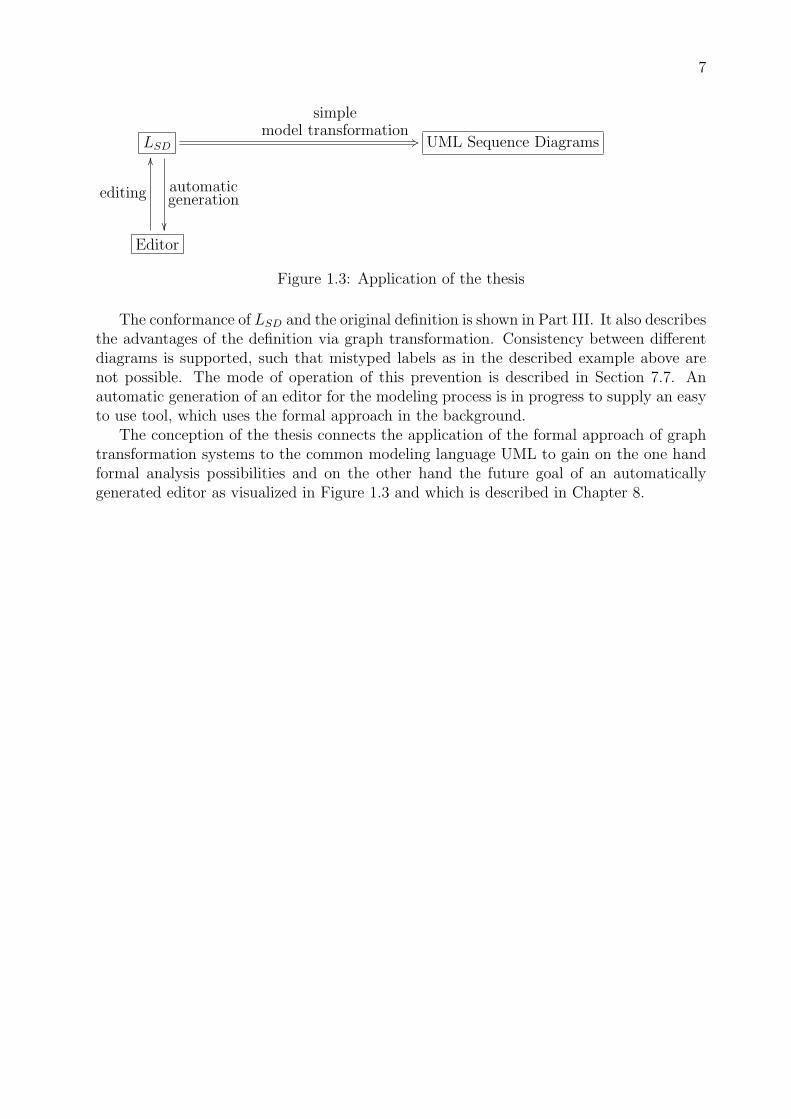
Figure 1.3: Application of the thesis
The conformance of LSD and the original definition is shown in Part III. It also describesthe advantages of the definition via graph transformation. Consistency between differentdiagrams is supported, such that mistyped labels as in the described example above arenot possible. The mode of operation of this prevention is described in Section 7.7. Anautomatic generation of an editor for the modeling process is in progress to supply an easyto use tool, which uses the formal approach in the background.
The conception of the thesis connects the application of the formal approach of graphtransformation systems to the common modeling language UML to gain on the one handformal analysis possibilities and on the other hand the future goal of an automaticallygenerated editor as visualized in Figure 1.3 and which is described in Chapter 8.

8 CHAPTER 1. INTRODUCTION

Part I
Graph Transformation and UMLSequence Diagrams
9


11
The visual language of Sequence Diagrams was defined by the Object ManagementGroup and their contributors. The redefinition of this language using the approach ofgraph transformations is named LSD and leads to some advantages. It provides on the onehand a strict formal definition and on the other hand possibilities for analysis in meansof consistency checks between diagrams and it constitutes the basis for an automaticallygenerated editor.
The syntax of a formal language describes how its elements look like or how they can beconstructed. As the UML is defined in the first way all elements have to fulfill the pattern,which is described. Chapter 3 contains this description and shows on the one hand theconcrete syntax elements of Sequence Diagrams, as they are defined in the UML super-structure [7] in Chapter 14. It defines how the diagram elements look like. On the otherhand it shows the abstract syntax of UML Sequence Diagrams, which provides all neces-sary information for the semantics of a diagram and leaves out the concrete information ofthe figure elements like positions and figure types.
LSD is defined in Part II in a constructive way using graph transformations of directedgraphs. These transformations are controlled by a set of rules with a left and a right handside. The left hand side of a rule describes the pattern in a graph, where some parts shallbe deleted and others shall be added and the right hand side defines the preserved andthe new elements in this pattern. Applying a rule is restricted by the gluing condition. Itprevents e.g. dangling edges, which do not have a source node or a target node. Figure 1.4shows a visualized schema of a rule, which alters the graph of the left hand side to becomethe right hand side. Circles, which are connected by lines indicate the graph structure. Theunderlying pictures show the meant representation of the graphs in the modeled domain.They indicate which elements are deleted and which added. The rule in this examplelaunches the body of a ship from the supporting stand into the water.
Figure 1.4: Visualization of a rule
A direct transformation, that uses this rule, can then launch a whole ship includingthe sail into the water, like it is visualized in Figure 1.5. The connection of the graph onthe left hand side of the rule to its context graph part in the applied graph is preserved.Therefore the ship’s body in this example remains connected to its sail. A graph rule canrewrite parts of a graph like a rule of a formal language rewrites parts of a word, butwith additional conditions. It is possible and useful to restrict the application of a rule tographs, that shall be transformable by this rule. In this example the condition, that therehas to be a valid authorization for launching the ship, would be appropriate.

12
Figure 1.5: Visualization of a transformation by the rule of Figure 1.4
A variety of approaches for formal graph transformations have been developed. Thenext chapter shortly introduces the approach with the categorical framework of a doublepushouts in the category of typed attributed graphs, which is based on the abstract theoryof Adhesive High Level Replacement Systems (AHLR) as they are defined in [5].

Chapter 2
Typed Attributed GraphTransformation
Graphs are used for describing the structure of systems in many areas, not only in computerscience but also in mathematical and economic sciences. Relations between different graphscan be simple inclusions, similarity or with more complexity a sequence of altering rules,which transform one graph to another. The latter relation will be defined in this chapterby using a formal categorical framework.
Apart from the structure of a system it is important to describe the data values, that canbe changed during the lifetime of this system. A combination of the structural and the valueinformation to an integrated specification is the extension of graphs to attributed graphs.The following section defines these graphs, but in addition with typing and inheritance.Type restrictions to graphs allow to distinguish between different parts in this graph andinheritance information represent hierarchy aspects of a system.
Section 2.2 specifies the steps for transforming one graph into another, which is the basisfor defining a graph grammar, that generates a formal language with graphs as its elementsstarting with a start graph. An extension of applying a rule to transform a graph is using atransformation unit. It allows to apply some rules in a certain sequence controlled by someoperators. Whenever a language contains elements, which are not reachable by applyinga single rule to a graph of the language these transformation units are very helpful. Asthe language consists of all elements, which are reachable from the start graph by a rule,either there are more elements or less than in the desired language. A grammar usingtransformation units consists of all elements which are reachable by transformation unitsand therefore allows these complex structures.
Beside transformation units also the amalgamation of rules [16] or nonterminals couldachieve these structures. Nonterminals in a reduced form can specify a flag, which indicates,that the transformation process is started and a checking rule may deletes this flag, if avalid instance is reached. But transformation units are a very intuitive and concise way ofcombining rules, such that this approach is taken.
2.1 Typed Attributed Graphs with Inheritance
Syntactical entities of a language can be modeled by graphs, which may be visualizedby dots, representing their nodes, and connecting arrows for the directed edges between
13

14 CHAPTER 2. TYPED ATTRIBUTED GRAPH TRANSFORMATION
them. There may be parallel edges, but also loops, which leave and enter the same node.Formal definitions in this chapter originate from the book ”Fundamentals of AlgebraicGraph Transformation” [5] in Chapters 2 and 9.
Definition 2.1 (Graph). A graph G = (V, E, source, target) consists of a set V of nodes(also called vertices), E of edges and two functions source, target : E → V , the sourceand target functions.
Esource
++
target
33 V
The integration of value information is realized by additional attribute nodes, whichare connected by new edges. This integrated graph is called E-graph.
Definition 2.2 (E-Graph). An E-graph G with G = (VG, VD, EG, ENA, EEA, (sourcej,targetj)j∈{G,NA,EA}) consists of sets
• VG and VD called graph and data nodes,
• EG, ENA, EEA called graph, node attribute, and edge attribute edges, and source andtarget functions
• sourceG : EG → VG, targetG : EG → VG for graph edges,
• sourceNA : ENA → VG, targetNA : ENA → VD for node attribute edges and
• sourceEA : EEA → EG, targetEA : EEA → VD for edge attribute edges.
EG
sourceG,,
targetG
22 VG
EEA
sourceEAyyyy
<<yyyy
targetEA
QQQQQQ
((QQQQQQQ
ENA
sourceNAEEEE
bbEEEE
targetNAmmmmmm
vvmmmmmmm
VD
The data elements themselves are structured by the use of algebras, such that thedata nodes represent some elements of the carrier sets of an specific data algebra. A datasignature defines the structure of the data algebra in the way that it delivers the skeletonof it. An E-graph together with a suitable algebra to a given data signature forms anattributed graph.
Definition 2.3 (Attributed Graph). Let DSIG = (SD, OPD) be a data signature withattribute value sorts S ′
D ⊆ SD. An attributed graph AG = (G, D) consists of an E-graphG together with a DSIG-algebra D such that ]s∈S′
DDs = VD.
As algebras may contain some carrier sets only for generating more complex sets, thecorresponding sorts in the signature are not needed in the attributed graph and thereforethe set of used sorts S ′
D may be restricted in comparison to SD. For transforming attributedgraphs it is necessary to define a simple relation between these graphs. The concept

2.1. TYPED ATTRIBUTED GRAPHS WITH INHERITANCE 15
of categories delivers a framework, that has objects, which are related by morphisms.The objects are in this case the attributed graphs and the morphisms attributed graphmorphisms. The steps for defining these morphisms is to concern first graphs, then E-graphs and finally attributed graphs.
Definition 2.4 (Graph Morphism). Given graphs G1, G2 with Gi = (V i, Ei, sourcei, targeti)for i = 1, 2. A graph morphism f : G1 → G2, f = (fV , fE) consists of two functionsfV : V 1 → V 2 and fE : E1 → E2 that preserve the source and target functions, i.e.fV ◦ source1 = source2 ◦ fE and fV ◦ target1 = target2 ◦ fE.
E1 source1 ,,target1
22
fE
��(=)
V 1
fV
��E2 source2 ,,
target222 V 2
Definition 2.5 (E-Graph Morphism). Consider E-graphs G1 and G2 with Gk = (V kG ,
V kD, Ek
G, EkNA, Ek
EA, (sourcekj , targetkj )j∈{G,NA,EA}) for k = 1, 2. An E-graph morphism f :
G1 → G2 is a tuple (fVG, fVD
, fEG, fENA
, fEEA) with fVi
: V 1i → V 2
i and fEj: E1
j → E2j for
i ∈ {G, D}, j ∈ {G, NA,EA} such that f commutes with all source and target functions,e.g. fVG
◦ source1G = source2
G ◦ fEG.
Definition 2.6 (Attributed Graph Morphism). For two attributed graphs AG1 =(G1, D1) and AG2 = (G2, D2) an attributed graph morphism f : AG1 → AG2 is a pairf = (fG, fD) with an E-graph morphism fG : G1 → G2 and an algebra homomorphismfD : D1 → D2 such that (1) commutes for all s ∈ S ′
D.
D1s
fD,s //� _
��(1)
D2s� _
��V 1
D fG,VD
// V 2D
Attributed graph morphisms are used in Section 2.2 for transformations but they arealso the basis for defining a type graph, which restricts the structure of graphs in a system.
Definition 2.7 (Typed Attributed Graph and Typed Attributed Graph Mor-phism). Given a data signature DSIG, an attributed type graph is an attributed graphATG = (TG, Z), where Z is the final DSIG-algebra. A typed attributed graph (AG, t)over ATG consists of an attributed graph AG together with an attributed graph morphismt : AG → ATG. A typed attributed graph morphism f : (AG1, t1) → (AG2, t2) is anattributed graph morphism f : AG1 → AG2 such that t2 ◦ f = t1.
ATG
(=)
AG1
t1::vvvvvvvvv
f// AG2
t2ddHHHHHHHHH

16 CHAPTER 2. TYPED ATTRIBUTED GRAPH TRANSFORMATION
The following examples of attributed graphs are shown in a compact notation accordingto UML class diagrams, where the attributes are written underneath the correspondingnodes or edges, respectively. This notation is also used in the graph transformation toolAGG for attributed graph grammars, which is used in the Tiger project as described inChapter 8.
Example of an Attributed Type Graph: The Structure of the German Legis-lature The German parliament consists of natural persons, who are in most cases alsomembers of parties. These parties have a chairman and can form a fraction in the parlia-ment, if they get enough votes.
Figure 2.1: Type graph for the parliament in Germany
Example of an Attributed Graph: An Abbreviation of the Concrete Structureof the German Legislature in 2004 In 2004 the German parliament consisted of thesefractions and three further members, not connected to a fraction. The Figure 2.2 showsonly one member per fraction, because the full parliament had 601 members.
Figure 2.2: Attributed graph typed over Figure 2.1
Abstraction and hierarchic structuring are useful methods for increasing the comprehen-sibility of a model leading in many cases to a faster and more secure development process,but also in average to smaller and more concise specifications. Node type inheritance fortype graphs empowers the modeler to define generalized and abstract nodes. These nodesare used to keep common information together and their relation represents hierarchicaldependencies to the other nodes. The benefits of decreasing the size and increasing thecomprehensibility occur usually at larger model specifications.
Definition 2.8 (Attributed Type Graph with Inheritance). An attributed typegraph with inheritance ATGI = (TG, Z, I, A) consists of an attributed type graph ATG =

2.1. TYPED ATTRIBUTED GRAPHS WITH INHERITANCE 17
(TG, Z), where TG is an E-graph TG = (TGVG, TGVD
, TGEG, TGENA, TGEEA, (sourcei,
targeti)i∈{G,NA,EA}) with TGVD= S ′
D and Z the final DSIG-algebra, and an inheritancegraph I = (IV , IE, s, t), with IV = TGVG
, and a set A ⊆ IV , called abstract nodes. Foreach node n ∈ IV the inheritance clan is defined byclanI(n) = {n′ ∈ IV | ∃ path n′ ∗→ n in I } ⊆ IV with n ∈ clanI(n).
The inheritance graph I delivers all generalization relations between the nodes of thetype graph TG. Abstract nodes in A define node types, which are not used for graphinstances typed over this type graph. These nodes will be helpful to reduce the amount ofrules for transforming graphs, as one abstract rule may define many concrete rules. The vi-sual representation integrates the inheritance graph I into TG by indicating generalizationedges by framed bold white arrow heads.
Definition 2.9 (Concrete Instance of ATGI). A concrete instance of an attributedtype graph with inheritance ATGI is an attributed graph typed over the concrete closureATG, i.e. (AG, type : AG→ ATG).
This closure is gained out of the inheritance graph I and the function clanI . A typedattributed graph morphism for graphs typed over ATGI has to be compatible with theextended type morphism to the concrete closure ATG.
Example of an Attributed Type Graph with Inheritance: The Structure ofthe German Legislature The concrete closure of this type graph is equivalent to thetype graph depicted in Figure 2.1. ”NamedElement” is an abstract node and defines theattribute ”name” for all other classes, thus this attribute has not to be defined for eachclass separately.
Figure 2.3: Type graph for the parliament in Germany using inheritance
The type graph in Figure 2.3 describes the structure for an arbitrary parliament in thepast 50 years in Germany and for all those which will come as long as the constitution isnot changing in this point. But the relation between two periods is not present.
For reusing the information of a graph the next section describes the transformation ofone to another. Some parts will be preserved and others altered or created, respectively. Inmeans of the German legislature this would deliver the possibility to keep all informationconnected to a former member of the parliament, if this member was again elected forthe new period. So the parliament has not to be created completely, but has only to bealtered by removing some past members and adding some new ones. Many systems in the

18 CHAPTER 2. TYPED ATTRIBUTED GRAPH TRANSFORMATION
real world can be reused, so it is a nearly natural idea to reuse models. The language ofSequence Diagrams contains all models, that describe interactions and are typed over itstype graph. These models are generated by applying rules of the grammar GGSD to avalid model, in the simplest case to the empty start graph. Therefore the reuse of modelsis widely used in graph grammars.
2.2 Typed Attributed Graph Transformation Systems
Graph transformation systems in general are used for model transformations as the one inChapter 6, but especially for defining a graph grammar, which generates a language. Agrammar for a language of typed attributed graphs, as it has been defined in the previoussection, consists of a type graph, a start graph and rules, to be able to generate eachlanguage element by applying a sequence of rules to the start graph. A rule is called graphproduction and can be applied to a graph. This application is called direct transformationand delivers a new graph H out of G.
Definition 2.10 (Typed Attributed Graph Production). Given an attributed typegraph ATG with data signature DSIG a typed attributed graph production, short produc-
tion, p = (Ll← K
r→ R) consists of typed attributed graphs L, K and R with commonDSIG-algebra TDSIG(X), the DSIG-termalgebra with variables X, and injective typed at-tributed graph morphisms l : K → L, r : K → R where the DSIG-part of l and r is theidentity on TDSIG(X).
A production is defined by the morphisms l and r. They have the common domain Kcalled gluing graph and its name originates from the German word ”Klebegraph”, whichis just the translation. Everything in K is preserved and the things in L but not in K aredeleted by the production. As R may also be larger than K all additional elements areadded by the production.
Example of a Graph Production: Deleting a Member of the Parliament Therule ”deleteMemberOfParliament” deletes the edge ”member of parliament” of a Personto his fraction, so that the whole graph after its application represents a parliament withone member less than before. For removing members, who are not integrated in a fraction,there has to be another rule. The numbers for the nodes indicate the morphisms l and r,thus the gluing graph contains these numbered elements and the connecting edges, whichalso occur in R.
Figure 2.4: Graph rule, which deletes one memeber of the parliament

2.2. TYPED ATTRIBUTED GRAPH TRANSFORMATION SYSTEMS 19
The left hand side L of a production describes the graph elements, which have to befound in the existing graph for applying this rule. The difference between L and K willbe deleted and all new elements in R will be added to this graph. An abstract rule hasnodes, whose type is an abstract node. It is equivalent to the concrete rules for eachspecialization and therefore reduces the amount of rules. Abstract nodes must not becreated, but only used by a rule. The application of a production to a graph is calleddirect graph transformation.
Definition 2.11 (Typed Attributed Graph Transformation). Given a production
p = (Ll← K
r→ R) as defined above and a typed attributed graph G with typed attributedgraph morphism m : L→ G, called match. A direct typed attributed graph transformationG
p,m⇒ H from G to a typed attributed graph H is given by the following double pushout(DPO) diagram in the category AGraphsATG, where (1) and (2) are pushouts.
L
m
��(1)
Kloo r //
k��
(2)
R
n
��G Dfoo g // H
A sequence G0 ⇒ G1 ⇒ . . .⇒ Gn of direct typed attributed graph transformations is calleda typed attributed graph transformation and is denoted as G0
∗⇒ Gn.H results by deleting everything, which is reached by L in G but not by K in D and
adding all new elements of R. The double pushout approach was already defined in [4].Applying a rule depends on the gluing condition, which prevents dangling edges and thedeletion of elements identified by m.
Example of a Graph Transformation: Deleting a Member of the ParliamentIn Figure 2.5 is applied the rule ”deleteMemberOfParliament()” to the graph G. Thegraph does not represent a complete parliament, but two members of a fraction, which areassigned to be representatives of their party in the parliament. One person has to leavethe parliament and he is selected by the match m. The numbers of the nodes indicate themorphisms and therefore the person ”Willy Brandt” is chosen to leave.
Furthermore extra conditions for a rule can be defined, such that its application isrestricted to matches m, which fulfill these conditions.
Definition 2.12 (Application Condition). An atomic application condition over atyped attributed graph L is of the form P (x,∨i∈Ixi), where x : L → X and xi : X → Ci
with i ∈ I for some index set I are (typed) graph morphisms. An application conditionover L is a Boolean formula over atomic application conditions over L.
L
m$$I
IIIIIIIIIIx // X
(=)
xi //
p
��
(=)
Ci
qizzttttttttttt
G
A typed attributed graph morphism m : L→ G satisfies an application condition acc, writ-ten m |= acc, if acc = P (x,∨i∈Ixi) and for all injective typed attributed graph morphismsp : X → G with p ◦ x = m there exists an i ∈ I and an injective typed attributed graphmorphism qi : Ci → G with qi ◦ xi = p.

20 CHAPTER 2. TYPED ATTRIBUTED GRAPH TRANSFORMATION
Figure 2.5: Graph transformation, which deletes a memeber of the parliament in G
For prohibiting a pattern in a graph when applying a rule a negative application con-dition is appropriate.
Definition 2.13 (Negative Application Condition). A simple negative applicationcondition is of the form NAC(x), where x : L→ X is a typed attributed graph morphism.A typed attributed graph morphism m : L→ G satisfies NAC(x) if there does not exist aninjective typed attributed graph morphism p : X → G with p ◦ x = m.
A positive application condition PAC(x) for a rule demands a pattern in a graph forits application and is just the negation of a negative application condition.
Definition 2.14 (Positive Application Condition). A simple positive application con-dition is of the form PAC(x), where x : L → X is a typed attributed graph morphism. Atyped attributed graph morphism m : L → G satisfies PAC(x) if there exists an injectivetyped attributed graph morphism p : X → G with p ◦ x = m.
Visualized rules with application conditions have a compact notation. The morphism xis implicit by the numbers of the nodes that are identified. The graph X is the visualizedpart of NAC or PAC together with all missing parts of L. This leads to a compact andconcise notation.
Considering an attributed type graph with inheritance ATGI the definition of a pro-duction has to be extended. The morphisms l and r have to be typed morphisms to ATGI,where x, xi may refine nodes. As abstract nodes do not appear in concrete graphs they arenot allowed to be created by a rule. The application of a rule needs an extend definitionfor a direct transformation. While f and g have to be typed over ATGI the morphismsm, k, n, p and qi may additionally refine nodes. This means, that if m refines n1 with typet1 to n2 with type t2, then the clan clanI(t2) must contain t1.
Languages can be defined by a graph grammar as defined below. Its elements aregenerated by applying some rules to the start graph.

2.2. TYPED ATTRIBUTED GRAPH TRANSFORMATION SYSTEMS 21
ci
qiPPPPPPP
''PPPPPPP
X
p@@
@
@@@
xioo L
m
��(1)
xoo Kloo r //
k��
(2)
R
n
��G Dfoo g // H
Figure 2.6: Graph transformation with application condition
Definition 2.15 (Typed Attributed Graph Grammar with Inheritance). A typedattributed graph grammar GG = (ATGI, P, S) consists of a type graph ATGI, a set oftyped attributed graph productions P and an attributed start graph S typed over ATGI.The typed attributed graph language L of GG is defined by L = {G | ∃ typed attributedgraph transformation S
∗⇒ G }.Complex language elements are sometimes the result of applying several rules in se-
quence to another element of the language. If the language shall not include the inter-mediate results these rule sequences have to be combined to create more complex rules,achieving the desired element in one step. This goal can be achieved by transformationunits as in [10], which can be used for transformation systems in general. But the specificsof the system type have to be defined by the corresponding transformation approach.
Definition 2.16 (Graph Transformation Approach). A graph transformation ap-proach is a tuple A = (G,R,⇒, C, E) where
• G is a class of graphs,
• R is a class of rules,
• ⇒ is a rule application operator yielding a binary relation⇒r⊆ G×G for each r ∈ R,
• C is a class of control conditions such that each C ∈ C specifies a binary relationSEME(C) ⊆ G × G for each mapping E : ID → 2G×G and
• E is a class of graph class expressions such that each X ∈ E specifies a set SEM(X) ⊆ G.
The graph transformation approach defines in general which kinds of graphs, rules andconditions shall be allowed. The operator SEM for the semantics is defined inductively,meaning that a condition over rules can be evaluated step wise. A transformation unituses these classes and specifies which of these elements it needs.
Definition 2.17 (Transformation Unit). A transformation unit over an approachA = (G,R,⇒, C, E) is a tuple tu = (I, T,R,C, U) where
• I is an initial graph class expression,
• T is a terminal graph class expression,
• R is a set of rules,
• C a control condition and
• U is a set of imported transformation units.

22 CHAPTER 2. TYPED ATTRIBUTED GRAPH TRANSFORMATION
I and T define subsets of E to restrict the possible matches for a transformation unitmeaning that a transformation unit is applicable, if the used graph is an initial graphand the resulting graph belongs to the set of T . The combined rules, which are applied,constitute R and the structure of the composition is defined by C, which can also useimported transformation units of U .
As this thesis uses typed attributed graph transformations with node type inheritanceand does not need all features of transformation units the used graph transformationapproach ATA = (GTA,RTA,⇒TA, CTA, ETA) with
- GTA = the class of typed attributed graphs,
- RTA = the class of productions as in definition 2.10,
- ⇒TA is a rule application operator according to transformations as in definition 2.11,
- CTA is the set RuleExp of rule expressions defined below and
- ETA = { all }, meaning that all graphs of GTA shall be allowed.
Let N be a nonterminal, which can be substituted to a name of a rule in R, then a ruleexpression E ∈ RuleExp has the following structure in BNF:
E :== N | (E ; E) | !(E)
The application of two rule expressions in a sequence is defined by the operator ”;”,whereas ”!” demands, that its operand has to be applied as long as possible. The followingdefinition of simple transformation units reduces the general definition of transformationunits to allow on the one hand the usage of control structures of CATGI , but which takesno advantage of restrictions via initial or terminal graph class expressions.
Definition 2.18 (Simple Transformation Unit). Given an attributed type graph withinheritance ATGI. A simple transformation unit stu = (R,C, U) is a transformation unittu over the approach ATA with tu = (all, all, R, C, U). R is a set of rules, which are usedby stu. C is a controll condition over R, U , and the two operators ”;” and ”!”, and U isthe set of imported simple transformation units.
Reconsidering the transformation system of the German parliament the next figuresshow how a simple transformation unit can be used and how it is visualized in this thesis.The rule deleteMemberOfParliament() removed the connection between a person andhis party of the type ”memberOfParliament”, such that this person is no longer a memberof the parliament.
Figure 2.8 now defines a simple transformation unit for changing a member of a parlia-ment. It uses the two rules ”addMemberOfParliament()” of Figure 2.7 and ”deleteMem-berOfParliament()” of Figure 2.5.
After applying ”changeMemberOfParliament()” the new graph has a new member andone old member less in the general case. Of course the new one can be the same person,which were deleted.
As the definition of a typed attributed graph grammar includes no transformationunits this definition has to be extended for using simple transformation units to define alanguage. Therefore the term controlled graph grammar is introduced basing on controlledgraph transformations.

2.2. TYPED ATTRIBUTED GRAPH TRANSFORMATION SYSTEMS 23
Figure 2.7: Rule for adding a member to the parliament
Figure 2.8: Simple transformation unit for changing a member of the parliament
Definition 2.19 (Controlled Graph Transformation). Given a simple transforma-tion unit stu = (R,C, U) and a typed attributed graph G with match m : L→ G, where Lbelongs to the first rule in C. A direct controlled graph transformation is a typed attributedgraph transformation with inheritance from G to H where stu describes the sequence ofrules, which have to be applied to G. The transformation can be performed if for all trans-formation steps there are matches for the rules, and the rules can be applied.
A sequence G0 ⇒∗ G1 ⇒∗ . . .⇒∗ Gn of direct controlled graph transformations is calleda controlled graph transformation and is denoted as G0
∗⇒ Gn.
As a controlled graph transformation is a typed attributed graph transformation itdefines constructively how to produce the resulting graph out of the given graph. But sim-ple transformation units increase the possibilities of a grammar as more complex relationsbetween the graphs can be defined, which are the criteria that they belong to the language.
Definition 2.20 (Controlled Graph Grammar). A controlled graph grammar GG =(ATGI, STU, SG) consists of a type graph ATGI, a set of simple transformation unitsSTU and a set of attributed start graphs SG typed over ATGI. The typed attributed graphlanguage L of GG is defined by L = {G | ∃ controlled graph transformation S
∗⇒ G,S ∈ SG}.
A controlled graph grammar is now sufficient enough to define the language of SequenceDiagrams. Beforehand the next chapter shows the existing MOF definition of UML Se-quence Diagrams.

24 CHAPTER 2. TYPED ATTRIBUTED GRAPH TRANSFORMATION

Chapter 3
Informal Introduction to UMLSequence Diagrams
3.1 Concrete Syntax
A developer who models a system just uses the concrete syntax of his modeling language,being e.g. rectangles, lines, circles or labels. Thus the following sections define the concretesyntax of UML Sequence Diagrams using the figures from the UML superstructure [7]. Bymeans of this definition the next chapter then defines the abstract syntax of UML SequenceDiagrams using a graph grammar.
3.1.1 Basic Components
As UML Sequence Diagrams define possible sequences of interactions between objects thefirst step for modeling is to put these objects into a frame. The following structures deliveranchor points for connecting theses objects via messages.
Frame All elements of a Sequence Diagram are put into a Frame, which is visualizedby a rectangle and a title at the upper left corner. The boldface ”sd” indicates that thisFrame is a Sequence Diagram.
Figure 3.1: Frame
25
26 CHAPTER 3. INFORMAL INTRODUCTION TO UML SEQUENCE DIAGRAMS
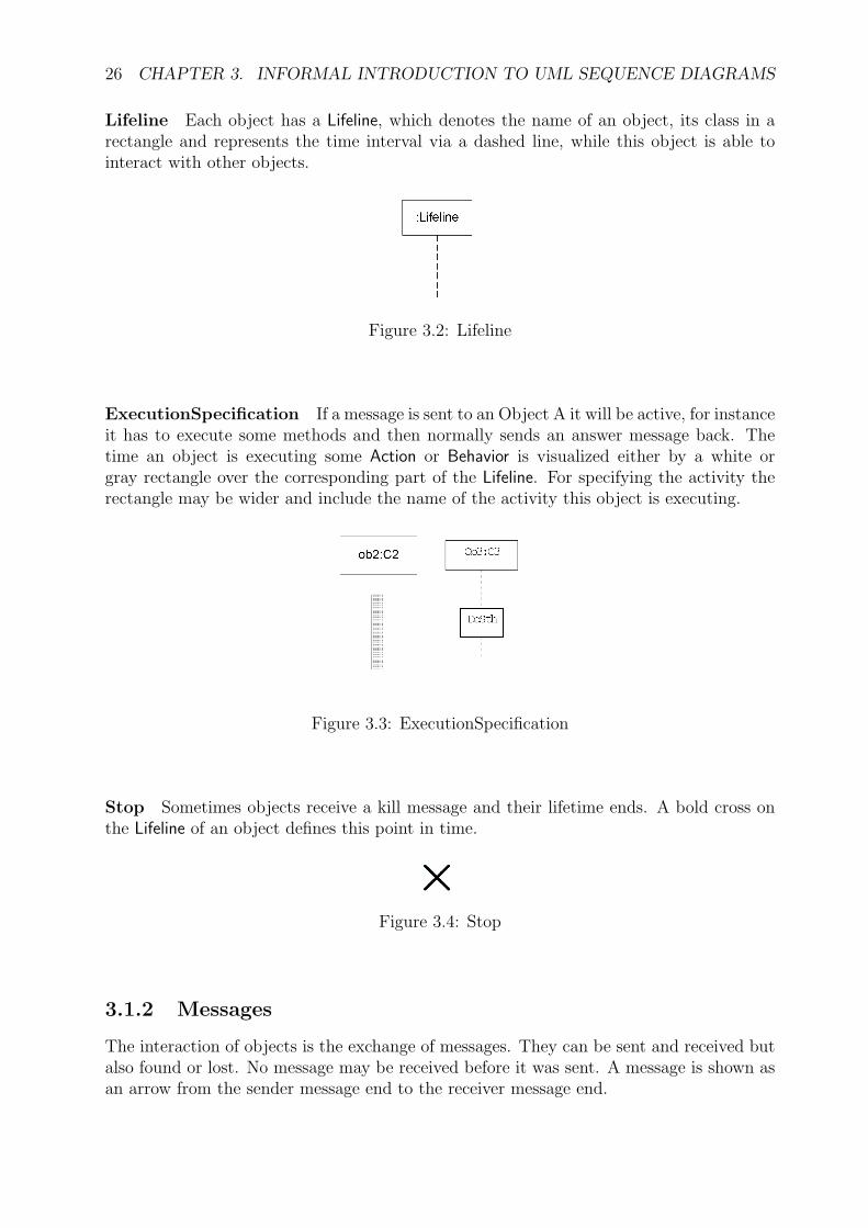
Lifeline Each object has a Lifeline, which denotes the name of an object, its class in arectangle and represents the time interval via a dashed line, while this object is able tointeract with other objects.
Figure 3.2: Lifeline
ExecutionSpecification If a message is sent to an Object A it will be active, for instanceit has to execute some methods and then normally sends an answer message back. Thetime an object is executing some Action or Behavior is visualized either by a white orgray rectangle over the corresponding part of the Lifeline. For specifying the activity therectangle may be wider and include the name of the activity this object is executing.
Figure 3.3: ExecutionSpecification
Stop Sometimes objects receive a kill message and their lifetime ends. A bold cross onthe Lifeline of an object defines this point in time.
Figure 3.4: Stop
3.1.2 Messages
The interaction of objects is the exchange of messages. They can be sent and received butalso found or lost. No message may be received before it was sent. A message is shown asan arrow from the sender message end to the receiver message end.

3.1. CONCRETE SYNTAX 27
Figure 3.5: Messages
Asynchronous message Whenever an object sends information to another object anddoes not require an answer to act further on it sends an asynchronous message. Thetransmitted information may be an operation call or a signal. In the visual view thearrow of an asynchronous operation call has a solid line whereas the sending of a signal isvisualized by a dashed line but both asynchronous Messages have an open arrow head.
Synchronous message If the sender of a message requires a reply this message is sentsynchronously. It is visualized by an arrow with a solid line like asynchronous operationcalls, but with a filled arrow head instead of the open one. The sender is not allowed tosend another message between the sending of a synchronous message and the reception ofthe corresponding reply.
Object creation message An object may send a Message to create another one. Thevisualization is analogous to a Message containing a Signal as mentioned before - a dashedline with an open arrow head. Unfortunately the UML shows in the example of Figure14.11 in [8] a solid line for the creation Message but defines the notation as declared before.
Lost and found messages After the sending of a Message it can be lost and in this caseis depicted with a filled black circle at its end instead of going to another Lifeline. FoundMessages start with a filled black circle at the beginning and do not start at a Lifeline.
Figure 3.6: Lost and Found Message
3.1.3 Combined Fragments
Sequence Diagrams can be unitized by CombinedFragments. They offer the possibility touse control structures to manage the message flow of different parts of a Sequence Diagram.The main advantage is a compact notation for complex behaviors, e.g. alternatives putdifferent message traces inside the same context to show that according to their conditionsat most one of these alternatives can be chosen. Other kinds are loop, critical block, andnegation. Visualization: A Rectangle surrounds the corresponding elements and on thetop left is a title which defines the kind of the CombinedFragment. The operands aredivided by a dashed line.

28 CHAPTER 3. INFORMAL INTRODUCTION TO UML SEQUENCE DIAGRAMS
Figure 3.7: CombinedFragment
3.1.4 Constraints
DurationConstraint The duration between two Events of sending or receiving a Mes-sage can be defined by a DurationConstraint. Visualization: The time range is placed inaccolade brackets and can use variables to define the dependency to other durations. TheConstraint is placed next to the Lifeline and between the points that it wants to restrict.The interval are marked by short lines and an arrow between the Constraint and the lines.
TimeConstraint Sending or receiving a Messages causes an Event, whose point in timecan be defined by a TimeConstraint. Visualization: A short line indicates the point in timethat is restricted and next to it is placed an expression for the TimeConstraint in accoladebrackets. It may use variables that refer to other points in time.
Figure 3.8: DurationConstraint and TimeConstraint
InteractionConstraint Defining alternatives needs to specify which operand of theCombinedFragment shall be chosen at runtime. Therefore InteractionConstraints can beplaced for each operand.

3.1. CONCRETE SYNTAX 29
Figure 3.9: Constraint for an InteractionOperand
StateInvariant Restrictions for a whole Lifeline can be defined via a StateIvariant. At-tributes of the connected object may be specified. The visual representation is shown inFigure 3.1.4.
Figure 3.10: StateInvariant
3.1.5 InteractionUse
Reusing diagrams as part of a new diagram preserves consistency that could be easilyviolated because of redundancy. Furthermore other diagram techniques for interactions,like communication diagrams, can be referenced. An InteractionUse offers connectionpoints, called Gates, to link in- and outgoing Messages of Sequence Diagrams to otherinteraction diagrams. Visualization: An InteractionUse is depicted as a rectangle with atitle ”ref” at the top left corner. Inside this frame is placed the name of the referencedInteraction.
Figure 3.11: InteractionUse
3.1.6 GeneralOrdering
As Messages, which do not depend on each other, may occur in an arbitrary order, the de-veloper is allowed to specify further restrictions. A GeneralOrdering between two points onLifelines demands, that whenever a Message shall be send from the second Lifeline beyond

30 CHAPTER 3. INFORMAL INTRODUCTION TO UML SEQUENCE DIAGRAMS
the GeneralOrdering, the first Lifeline has to reach at least the beginning of the GeneralOrder-ing before. It is visualized by a dashed line with a filled arrow head somewhere on the line,but not at an end, going from one Lifeline to another.
Figure 3.12: GeneralOrdering
3.2 MOF definition for UML Sequence Diagrams (Overview)
The meta-model of UML is defined using the MOF approach containing also constraints forrestricting the valid instances. This chapter shows this model together with an argumen-tation for the validity of the multiplicity constraints and references to the correspondingpages for the general constraints.
3.2.1 Classes and Associations
UML Interactions are general Sequence Diagrams and their meta-model is shown in thissubsection. Events model notification points, which can be listened by other componentsof the system. They can signalize the sending of a Message, the creation or destruction ofan object or the execution of a behavior or an action.
Figure 3.13: Events

3.2. MOF DEFINITION FOR UML SEQUENCE DIAGRAMS (OVERVIEW) 31
Events The sending of a Message is signalized by Events, which are created exclusively bythe rules for the creation of Messages in GGSD. Theses rules connect them to exactly oneOperation or Signal, respectively. The multiplicity constraints in Figure 3.13 are thereforerespected.
Figure 3.14: Interaction
InteractionFragments Figure 3.14 shows the devision of Interactions into InteractionFrag-ments. As the rules of GGSD create fragments in the way, that they are connected to anInteraction the multiplicity constraint for the edge enclosingInteraction is followed. A StateIn-variant is created in Figure 5.8 together with its defining Constraint which corresponds tothe other multiplicity in this figure.
Lifelines The connection between Classes and Interactions bases on Lifelines, as they arelinked to the roles of the Classes specified by ConnectableElements. The following list con-tains all multiplicity restrictions together with the argumentation, that they are respectedby GGSD.
Multiplicity Argumentationinteraction (1) When a Lifeline is being created it is connected to the enclosing
Interaction.covered (1) As before during the creation of an OccurrenceSpecification or a
StateInvariant they are connected to the desired Lifeline.represents (0..1) ConnectableElements are connected to the Lifeline during the latter
one is being created.selector (0..1) As no multivalued elements occur in LSD this edge is not present.

32 CHAPTER 3. INFORMAL INTRODUCTION TO UML SEQUENCE DIAGRAMS
Figure 3.15: Interaction fragments
OccurrenceSpecifications Points on a Lifeline are modeled by OccurrenceSpecificationsto deliver the anchors for Messages and ExecutionSpecifications.
Multiplicity Argumentationevent (1) There are some blind OccurrenceSpecifications in LSD for creating
CombinedFragments. They are deleted via the model transformationin Chapter 6, such that afterward the constraint is followed.
before (1) A GeneralOrdering is created between two OccurrenceSpecificationsin Figure 5.37.
after (1) As before.start (1) Creating an ExecutionSpecification by the rule in Figures 5.10 to 5.9
produces also the connection to its start and finish ExecutionOccur-renceSpecification.
finish (1) As before.execution (1) As before.action (1) The rule in Figure 5.9 creates the ActionExecutionSpecification to-
gether with the connection to its Action.behavior (0..1) As before the rule in Figure 5.10 connects the specification to the
corresponding Behavior.

3.2. MOF DEFINITION FOR UML SEQUENCE DIAGRAMS (OVERVIEW) 33
Figure 3.16: Occurrence specifications

34 CHAPTER 3. INFORMAL INTRODUCTION TO UML SEQUENCE DIAGRAMS
Figure 3.17: Combined fragments
CombinedFragments Control structures for sequence diagrams are specified by Com-binedFragments in Figure 3.17. They have at least on operand.
Multiplicity ArgumentationenclosingOperand(0..1)
This edges is added during the model transformation in Chapter 6.As CombinedFragments do not cover common fragments there canbe at most on operand for each fragment.
operand (1..*) CombindFragments are inserted together with the first operand. AnInteractionOperand is only connected to a CombindFragments duringits creation.
guard (0..1) InteractionConstraints are connected to an InteractionOperand duringtheir creation.
minint (0..1) The specifiction minint and maxint are inserted together with anInteractionConstraint for a CombinedFragment representing a loop.
maxint (0..1) As before.
Messages Sending information from one object in an Interaction to another one is de-fined by Messages. They are shown in Figure 3.18.

3.2. MOF DEFINITION FOR UML SEQUENCE DIAGRAMS (OVERVIEW) 35
Figure 3.18: Messages
Multiplicity Argumentationinteraction (1) The rules for creating Messages connect the Messages with the en-
closing Interaction.sendEvent(0..1) Creating rules for Messages also connect them to the MessageEnds,
if desired.receiveEvent(0..1) As before.message(0..1) This edges is only inserted during the model transformation in
Chapter 6.signature (0..1) Each Message is connected during its creation to an Operation or a
Signal with an edge of type signature.argument As an Operation may be called by a Message with arguments of the
same value, if they are of the correct type, the restriction ”0..1” isnot sensible.
connector (0..1) Connectors are not specified in LSD.event (1) This connection is placed during the creation of a Message. All
additional OccurrenceSpecifications are deleted during the modeltransformation.

36 CHAPTER 3. INFORMAL INTRODUCTION TO UML SEQUENCE DIAGRAMS
InteractionUses Modularization of Sequence Diagrams is realized by InteractionUses,which refer to an Interaction already defined elsewhere. The edge argument should re-fer to a TypedElement, as Actions are no sensible arguments. Additionally it should not berestricted, as an Interaction could be called with Parameters of the same value. During thecreation of an InteractionUse it is connected to the referenced Interaction, which respectsthe multiplicity. PartDecompositions are not specified in LSD.
Figure 3.19: Interaction uses
Gates Connecting Messages with the frame of an Interaction or an InteractionUse is real-ized by Gates. They provide the sending of Messages between these InteractionFragmentsand they are inserted together with their connecting edge to the Interaction or Interac-tionUse, respectively. This connection is not created in other transformations, such thatthe demanded multiplicity is respected.
Figure 3.20: Gates
Beside the graphs shown above the language description of UML Interactions containsalso constraints, which are mainly defined in natural language.
3.2. MOF DEFINITION FOR UML SEQUENCE DIAGRAMS (OVERVIEW) 37
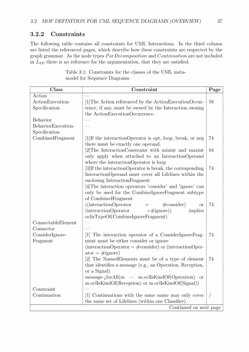
3.2.2 Constraints
The following table contains all constraints for UML Interactions. In the third columnare listed the referenced pages, which describe how these constraints are respected by thegraph grammar. As the node types ParDecomposition and Continuation are not includedin LSD there is no reference for the argumentation, that they are satisfied.
Table 3.1: Constraints for the classes of the UML meta-model for Sequence Diagrams.
Class Constraint PageAction —ActionExecution-Specification
[1]The Action referenced by the ActionExecutionOccur-rence, if any, must be owned by the Interaction owningthe ActionExecutionOccurrence.
58
Behavior —BehaviorExecution-Specification
—
CombinedFragment [1]If the interactionOperator is opt, loop, break, or negthere must be exactly one operand.
74
[2]The InteractionConstraint with minint and maxintonly apply when attached to an InteractionOperandwhere the interactionOperator is loop
84
[3]If the interactionOperator is break, the correspondingInteractionOperand must cover all Lifelines within theenclosing InteractionFragment
74
[4]The interaction operators ’consider’ and ’ignore’ canonly be used for the CombineIgnoreFragment subtypeof CombinedFragment((interactionOperator = #consider) or(interactionOperator =#ignore)) impliesoclisTypeOf(CombineIgnoreFragment)
74
ConnectableElement —Connector —ConsiderIgnore-Fragment
[1] The interaction operator of a ConsiderIgnoreFrag-ment must be either consider or ignore
74
(interactionOperator = #consider) or (interactionOper-ator = #ignore)[2] The NamedElements must be of a type of elementthat identifies a message (e.g., an Operation, Reception,or a Signal)
74
message-¿forAll(m — m.oclIsKindOf(Operation) orm.oclIsKindOf(Reception) or m.oclIsKindOf(Signal))
Constraint —Continuation [1] Continuations with the same name may only cover
the same set of Lifelines (within one Classifier)./
Continued on next page

38 CHAPTER 3. INFORMAL INTRODUCTION TO UML SEQUENCE DIAGRAMS
Table 3.1 – continued from previous pageClass Constraint Page
[2] Continuations are always global in the enclosing In-teractionFragment e.g. it always covers all Lifelines cov-ered by the enclosing InteractionFragment.
/
[3] Continuations always occur as the very first Inter-actionFragment or the very last InteractionFragment ofthe enclosing InteractionFragment.
/
CreationEvent —DestructionEvent [1] No other OccurrenceSpecifications may appear below
an OccurrenceSpecification which references a Destruc-tionEvent on a given Lifeline in an InteractionOperand.
63
Event —ExecutionEvent —ExecutionOccurrence-Specification
—
ExecutionSpecification [1] The startEvent and the finishEvent must be on thesame Lifelinestart.lifeline = finish.lifeline 58
Gate [1] The message leading to/from an actualGate of anInteractionUse must correspond to the message leadingfrom/to the formal Gate with the same name of theInteraction referenced by the InteractionUse.
97
[2] The message leading to/from an (expression) Gatewithin a CombinedFragment must correspond to themessage leading from/to the CombinedFragment on itsoutside.
97
GeneralOrdering — :better: not against message orders, timeline orderInteraction —InteractionConstraint [1] The dynamic variables that take part in the con-
straint must be owned by the ConnectableElement cor-responding to the covered Lifeline.
83
[2] The constraint may contain references to global dataor write-once data.
83
[3] Minint/maxint can only be present if the Interac-tionConstraint is associated with the operand of a loopCombinedFragment.
84
[4] If minint is specified, then the expression must eval-uate to a non-negative integer.
83
[5] If maxint is specified, then the expression must eval-uate to a positive integer.
83
[6] If maxint is specified, then minint must be specifiedand the evaluation of maxint must be ¿= the evaluationof minint.
83
InteractionFragment —Continued on next page

3.2. MOF DEFINITION FOR UML SEQUENCE DIAGRAMS (OVERVIEW) 39
Table 3.1 – continued from previous pageClass Constraint Page
InteractionOperand [1] The guard must be placed directly prior to (above)the EventOccurrence that will become the first Even-tOccurrence within this InteractionOperand.
74
[2] The guard must contain only references to values lo-cal to the Lifeline on which it resides, or values global tothe whole Interaction (See InteractionConstraint (fromFragments) on page 528).
83
InteractionUse [1] Actual Gates of the InteractionUse must match For-mal Gates of the referred Interaction. Gates match whentheir names are equal.
88
[2] The InteractionUse must cover all Lifelines of theenclosing Interaction which appear within the referredInteraction.
88
[3] The arguments of the InteractionUse must corre-spond to parameters of the referred Interaction.
88
[4] The arguments must only be constants, parametersof the enclosing Interaction or attributes of the classifierowning the enclosing Interaction.
88
Lifeline [1] If two (or more) InteractionUses within one Interac-tion, refer to Interactions with common Lifelines, thoseLifelines must also appear in the Interaction with the In-teractionUses. By common Lifelines we mean Lifelineswith the same selector and represents associations.
88
[2] The selector for a Lifeline must only be specified ifthe referenced Part is multivalued.(self.selector-¿isEmpty() implies notself.represents.isMultivalued()) or (not self.selector-¿isEmpty() implies self.represents.isMultivalued())
54
[3] The classifier containing the referenced Con-nectableElement must be the same classifier, or an an-cestor, of the classifier that contains the interaction en-closing this lifeline.if (represents-¿notEmpty()) then (if selector-¿notEmpty() then represents.isMultivalued() elsenot represents.isMultivalued())
55
Message [1] If the sending MessageEvent and the receiving Mes-sageEvent of the same Message are on the same Lifeline,the sending MessageEvent must be ordered before thereceiving MessageEvent. Issue 7328 - remove referenceto synchSignal
71
Continued on next page

40 CHAPTER 3. INFORMAL INTRODUCTION TO UML SEQUENCE DIAGRAMS
Table 3.1 – continued from previous pageClass Constraint Page
[2] The signature must either refer an Operation(in which case messageSort is either synchCall orasynchCall) or a Signal (in which case messageSort isasynchSignal). The name of the NamedElement ref-erenced by signature must be the same as that of theMessage.
71
[3] In the case when the Message signature is an Opera-tion, the arguments of the Message must correspond tothe parameters of the Operation. A Parameter corre-sponds to an Argument if the Argument is of the sameClass or a specialization of that of the Parameter.
71
[4] In the case when the Message signature is a Signal,the arguments of the Message must correspond to theattributes of the Signal. A Message Argument corre-sponds to a Signal Attribute if the Arguement is of thesame Class or a specialization of that of the Attribute.
71
[5] Arguments of a Message must only be: 71i) attributes of the sending lifelineii) constantsiii) symbolic values (which are wildcard values repre-senting any legal value)iv) explicit parameters of the enclosing Interactionv) attributes of the class owning the Interaction[6] Messages cannot cross bounderies of CombinedFrag-ments or their operands.
71
[7] If the MessageEnds are both OccurrenceSpecifica-tions then the connector must go between the Parts rep-resented by the Lifelines of the two MessageEnds.”
71
MessageEnd —MessageEvent —MessageOccurence-Specification
—
NamedElement —NameSpace —Occurrence-Specification
—
OpaceExpression —Operation —PartDecomposition [1] PartDecompositions apply only to Parts that are
Parts of Internal Structures not to Parts of Collabora-tions.
/
Continued on next page
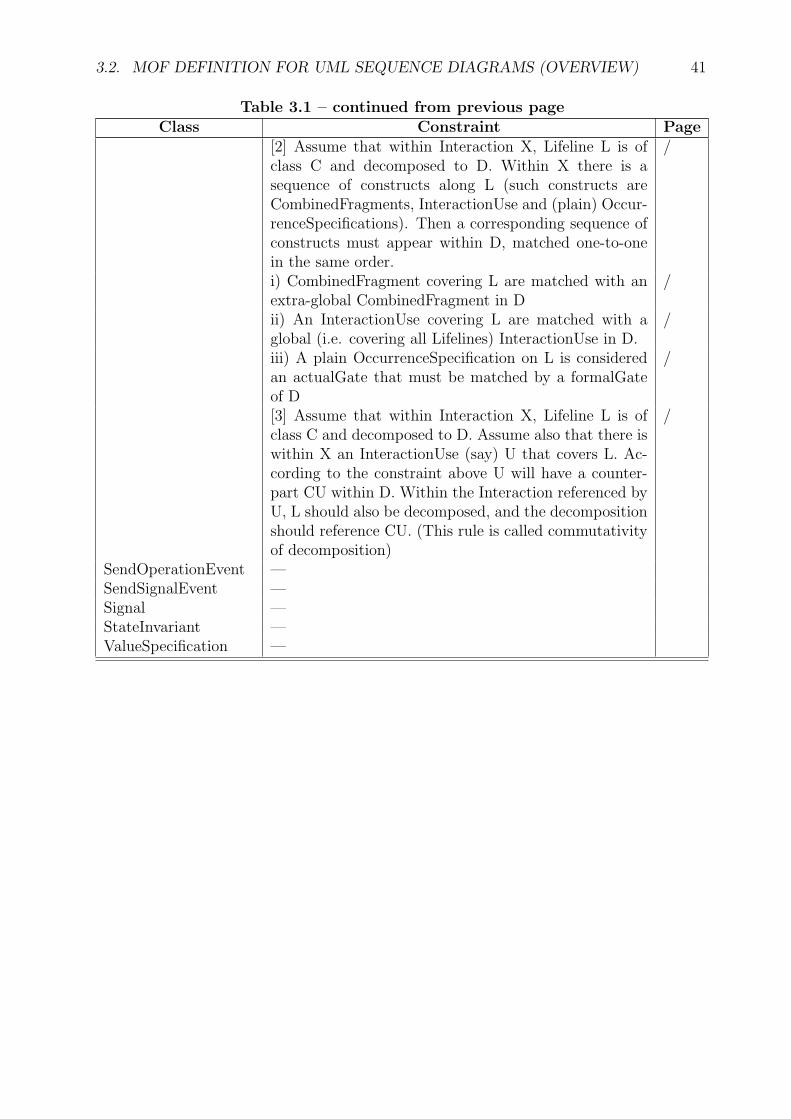
3.2. MOF DEFINITION FOR UML SEQUENCE DIAGRAMS (OVERVIEW) 41
Table 3.1 – continued from previous pageClass Constraint Page
[2] Assume that within Interaction X, Lifeline L is ofclass C and decomposed to D. Within X there is asequence of constructs along L (such constructs areCombinedFragments, InteractionUse and (plain) Occur-renceSpecifications). Then a corresponding sequence ofconstructs must appear within D, matched one-to-onein the same order.
/
i) CombinedFragment covering L are matched with anextra-global CombinedFragment in D
/
ii) An InteractionUse covering L are matched with aglobal (i.e. covering all Lifelines) InteractionUse in D.
/
iii) A plain OccurrenceSpecification on L is consideredan actualGate that must be matched by a formalGateof D
/
[3] Assume that within Interaction X, Lifeline L is ofclass C and decomposed to D. Assume also that there iswithin X an InteractionUse (say) U that covers L. Ac-cording to the constraint above U will have a counter-part CU within D. Within the Interaction referenced byU, L should also be decomposed, and the decompositionshould reference CU. (This rule is called commutativityof decomposition)
/
SendOperationEvent —SendSignalEvent —Signal —StateInvariant —ValueSpecification —

42 CHAPTER 3. INFORMAL INTRODUCTION TO UML SEQUENCE DIAGRAMS

Part II
Graph Grammar for UML SequenceDiagrams
43

45
Sequence Diagrams are integrated in the visual language UML. This part applies a con-structive way to define visual languages using typed attributed graph transformations withnode type inheritance, which were described in Chapter 2. The controlled graph grammarGGSD generates the language LSD of graphs representing Sequence Diagrams, such thatLSD = L(GGSD). Language elements are graphs, which can easily be transformed intoinstances of Sequence Diagrams, that are valid in the UML meta-model. This transforma-tion is defined in Chapter 6. The instances are abstract, so they do not contain the specialvisual data how they can be drawn, like position, size and figure types, but everything,what is needed to interpret them semantically.
The controlled graph grammar GGSD = (ATGISD, STUSD, SGSD) consists of a typedattributed graph with node type inheritance ATGISD, a set of simple transformation unitsSTUSD and a set of start graphs SGSD. At the beginning the type graph and the startgraphs are defined in Chapter 4. Chapter 5 then defines the simple transformation unitswhich generate the language LSD out of the start graphs following the typing restrictions.As some transformations are more complex then others, their corresponding simple trans-formation unit is a composition of rules where other units just include one rule.

46

Chapter 4
Type Graph and Start Graphs
The attributed graph ATGISD is the type graph of the grammar GGSD and will be definedby the following figures. They start with the basic elements of a Sequence Diagram, thenspecify different kinds of Events, integrate Behaviors and Actions, define containments andsynchronized areas, and finally Arguments of Messages and InteractionUses. The attributetypes are defined by the final Algebra ZSD of the signature in Figure 4.1 and in caseof the attribute sort ”string” it is assumed, that the instances of the language shall beattributed with an algebra which has a common definition for the sort ”string” meaninga concatenation of characters. As Sequence Diagrams base on the information of a classdiagram their type graph includes the type graph of class diagrams, which is included inthe graph grammar for class diagrams in Appendix A.
The complete type graph ATGISD is constructed by composing all following parts andthe type graph of GGCD in Appendix A. Nodes with identical names are glued together.The set SGSD of start graphs consists of all class diagrams, which can be created by thegraph grammar GGCD shown in Appendix A.
4.1 Basic Elements
Each Sequence Diagram is defined by an instance of the node type Interaction, which islocated at the top left of Figure 4.1. It may contain Messages, Lifelines and fragments,as it is connected to the node types Message, Lifeline and InteractionFragment. Messagesnormally lead from one Lifeline to another. The anchor points at the Lifelines are of thetype MessageEnd. In the average case they are MessageOccurrenceSpecification, which hasa strict successor edge ”next” for the order on the same Lifeline and a general ordering edge”order”, which allows to define the sequential order requirements of a Sequence Diagram,that are results of the dependencies between different Messages. Furthermore the nodetype GeneralOrdering provides an explicit way of defining sequential restrictions betweenpoints on Lifelines. Gates are the other specialization of MessageEnds allowing to createMessages from an Interaction to a referenced Interaction and vise versa.
CombinedFragments allow to define control structures, like alternatives, loops or parallelregions over parts of the Sequence Diagram. Further restrictions to these control structurescan be defined by Constraints of type InteractionConstraint.
47

48 CHAPTER 4. TYPE GRAPH AND START GRAPHS
Figure 4.1: Main type elements
4.2 Attributes
The Figure 4.2 shows a compact notation of the enumeration types for some attributes. Itfollows the UML syntax for class diagrams and the attribute types are formally specified inTable 4.1 by their signature. The InteractionOperator is an attribute type for the attributeInteractionOperator of CombinedFragments. They define the kind of the CombinedFragment:
alt An alternative requires, that at most one operand is chosen in a sequence. Operandscan be restricted by guards, thus they can not be chosen, if the guard evaluates tofalse.
assert The sequence of the Messages in the assertion block is the only valid continuationafter the preceding Messages of the Interaction have been send. Other continuationsin other parts or Interactions are illegal, except if their distinction to the assertionis covered by hidden Messages given by a consider or ignore block surrounding theassertion.
break The ”break” operand stops the execution of the remainder of the enclosing frag-ment. It is chosen in dependency of its guard, or non-deterministically otherwise.
critical The critical region is treated atomically, thus its OccurrenceSpecifications cannotbe interleaved by other OccurrenceSpecifications outside this fragment.
consider/ignore A region labeled with consider hides all Messages, which are not declaredby this operand. An ignore operand hides exactly the Messages that are declared byit.
neg A CombinedFragment with the operator ”neg” defines traces, which are not allowedto occur.
opt An optional part of the sequence can be defined by the operand ”opt”, which definesthat its content may be a part of the trace, but does not have to.

4.2. ATTRIBUTES 49
parallel The Event occurrences of the different operands can interleave in any order aslong as the ordering structure inside each operand is preserved.
seq Weak sequences are restricted parallel fragments, which also respect the ordering ofOccurrenceSpecifications of different operands as long as they are on the same Lifeline.
strict Strict sequencing demands to preserve the ordering of the operands.
Figure 4.2: Attributes in short notation
Messages have attributes, which are typed over two enumeration types. The sort ”synch-Call” defines a Message, which calls an operation and has to be replied before the sender isable to send another Message. Asynchronous operation calls are defined by ”asynchCall”and the simple case of sending a Signal is specified by the sort ”asynchSignal”. Messagesnormally start at its sender and reach the recipient, thus their kind is ”complete”. Oth-erwise it is ”lost”, if the Message does not reach the recipient, or ”found”, if the sender isunknown.
The next table defines the signature DSIGSD. Algebras to this signature are used forattribution of instances of the graph language LSD. Each element of an enumeration typeis already defined as a constant in the signature.
sorts : InteractionOperatorMessageKindMessageSortcharstring
opns : alt : → InteractionOperatorassert : → InteractionOperatorbreak : → InteractionOperatorconsider : → InteractionOperatorcritical : → InteractionOperatorignore : → InteractionOperatorloop : → InteractionOperatorneg : → InteractionOperatoropt : → InteractionOperatorpar : → InteractionOperatorseq : → InteractionOperatorstrict : → InteractionOperator

50 CHAPTER 4. TYPE GRAPH AND START GRAPHS
complete : →MessageKindlost : →MessageKindfound : →MessageKind
synchCall : →MessageSortasynchCall : →MessageSortasynchSignal : →MessageSort
a : → char...Z : → char
empty : → stringmake : char → stringconcat : string string → string
Table 4.1: Signature of the attributes
4.3 Events
Each changing of the system state is viewable by the occurrence of an Event. Whencreating an object the system generates a CreationEvent and vise versa at the time ofdestroying an object a DestructionEvent is produced. Execution events define the startof an Action or Behavior, which is executed by the object of the referenced Lifeline. Thesending and receiving of Messages from one Lifeline of an object to an other is detectableby the corresponding specializations of MessageEvent. They refer to the Signal, which wassend, or the Operation, that was called.
Figure 4.3: Event hierarchy

4.4. EXECUTION SPECIFICATIONS 51
4.4 Execution Specifications
After receiving an operation call or a Signal, that requires a reaction, this object has tobe active. The range of the active period at the timeline is specified by an ExecutionSpec-ification, which defines a start and a finish point at the Lifeline and is connected to thecorresponding Action or Behavior, that has to be executed.
Figure 4.4: Execution Specifications
4.5 Container Structures
Sequence Diagrams provide the feature to unitize the elements of a diagram. Combined-Fragments can surround communication parts, to define special control structures on them.The ”begin” and ”end” edges define their boundaries. A specialization of CombinedFrag-ment is the ConsiderIgnoreFragment, which may include a set of Message to be exclusivelyor inclusively hidden. As its name says, the InteractionOperator of this CombinedFragmenthas to be either consider or ignore.
A special case of an InteractionFragment is the InteractionUse, which allows to use an-other Sequence Diagram as a part of the new one.
Figure 4.5: Containments
Concurrent processing of data often needs synchronization, which can be specified bythe node type ”Synchronization”. The ”begin” and ”end” edges define the start and end

52 CHAPTER 4. TYPE GRAPH AND START GRAPHS
point in time for an object, when it is waiting for an answer. Within these points in timethe object is blocked for sending any other Message. StateInvariants define conditions forthe object of the Lifeline to be satisfied at runtime.
Figure 4.6: Synchronization of Messages and StateInvariants
4.6 Named Elements
Some node types have the common attribute ”name” and are therefore a specialization ofNamedElement.
name : stringNamedElement
Message
GeneralOrdering InteractionFragment
Lifeline
ConnectableElement
Classifier
MessageEnd
ParameterEvent
1
Figure 4.7: Elements with a name
4.7 Arguments of Messages and InteractionUses
Messages have arguments, if the called Operation or the sent Signal has parameters. AnInteractionUse has arguments, if the referenced Interaction has parameters. The corre-spondence between an argument and a parameter follows by the attribute ”order” of theedges ”argument” and ”parameter”. As only the specializations of ”Argument” appear ininstances of LSD this class is abstract.
Figure 4.8: Arguments of Messages and InteractionUses

Chapter 5
Rules and Simple TransformationUnits
After defining the type graph of the graph grammar the following rules and simple trans-formation units complete the abstract syntax definition of LSD, the language of SequenceDiagrams. They allow to construct language elements directly, such that the languagedefinition is not only descriptive. The constraints shown in Section 3.2 are concerned andtheir realization is described directly at the corresponding rules. At the end of this chapteris located a table listing all simple transformation units of GGSD.
5.1 Basic Components
Main nodes of Sequence Diagrams are of course its container - a node of type Interaction,but also Lifelines and OccurrenceSpecifications. Their creation is defined by the followingrules for basic components.
Each Sequence Diagram is a special visualization of an Interaction, which leads to somerestrictions in the abstract syntax in comparison to Interactions at all. Nevertheless Se-quence Diagrams are instances of the type Interaction and their specifics are not presentdirectly in the abstract syntax. The first step of creating a sequence diagram is thereforeto create a new Interaction by the rule in Figure 5.1 and to fill it afterwards with content.
Figure 5.1: Rule createInteraction()
An Interaction may have parameters to use them as arguments for Messages between ob-jects. They can be transferred by other Behaviors, which use the Interaction as a component.The rule ”addParameterInt()” in Figure 5.2 adds a new parameter to the Interaction, whereNAC ensures, that it is not connected to an InteractionUse. Otherwise the InteractionUsewould not assign all necessary parameters.
53

54 CHAPTER 5. RULES AND SIMPLE TRANSFORMATION UNITS
Figure 5.2: Rule addParameterInt()
Lifelines are a connection point of Sequence Diagrams to class diagrams and they showthe restricted view of its class to the sequence of Interactions. The rule createLifeline()in Figure 5.3 also produces the first OccurrenceSpecification, which is an anchor point toconnect it with other objects via Messages. The negative application conditions NAC1 andNAC2 demand, that Lifelines may only be created in the Interaction, if it is not connectedby an InteractionUse. This condition is needed for the rules in Subsection 5.5 and ensuresthat hierarchical structured Interactions remain consistent.
Figure 5.3: Rule createLifeline()
In the next list the effected constraints for Interactions of the UML are shown as wellas an argumentation, that they are satisfied. As the rules of GGSD and the constraints inthe UML specification are local to some classifiers, respectively node types, the constraintscan be handled locally at the rules, which touch them.
Affected constraints, class: Lifeline
[2] The selector for a Lifeline must only be specified if the referenced Part is multival-ued.(self.selector-¿isEmpty() implies not self.represents.isMultivalued()) or (not self.selector-¿isEmpty() implies self.represents.isMultivalued())This constraint in OCL syntax is always true and does not restrict GGSD in written En-glish, as there is no selector present. A selector for multivalued classifiers like arrays wouldbe an extension for GGSD. The correct OCL constraint for [2] is written by mistake in [3].

5.1. BASIC COMPONENTS 55
[3] The classifier containing the referenced ConnectableElement must be the same clas-sifier, or an ancestor, of the classifier that contains the Interaction enclosing this Lifeline.if (represents-¿notEmpty()) then (if selector-¿notEmpty() thenrepresents.isMultivalued() else not represents.isMultivalued())The last constraint restricts the possible classifiers of Lifelines to just the one of the In-teraction or its ancestors. This restriction is not sensible, as objects communicate viaassociations in the class diagram and do not have to be in a generalization relation.
To connect Lifelines by some Messages in a special order it is necessary to create moreOccurrenceSpecifications. They are created by the rule in Figure 5.4. A new Occurrence-Specification OS is placed directly behind an ending one of a Lifeline. Synchronized areasare handled by the rule in Figure 5.6 and therefore are forbidden by NAC1. NAC2 isdefined in Figure 5.5.
Figure 5.4: Rule addOS()
For inserting new OccurrenceSpecifications the following negative application conditionsare used. NAC1 forbids a CombinedFragment as enclosing fragment for the precedingOccurrenceSpecification OS. Without this condition the order structure to other operandsof the CombinedFragment would be validated. The second condition ensures, that this OSis the last one of the Lifeline. Finally the last condition prohibits a continuation of a Lifelinebeyond the destruction of its related classifier.

56 CHAPTER 5. RULES AND SIMPLE TRANSFORMATION UNITS
Figure 5.5: Negative application conditions for the rule addOS()
Figure 5.6 describes the creation of a new OccurrenceSpecification at the end of a syn-chronized area. Those areas can be created by rules for synchronous Messages in Subsection5.2. An object, which has sent a synchronous Message, has to wait for a reply before itis able to send again. Therefore the synchronized area has to cover everything from thesending point till the reply point. If the latter one is not present it has to cover everyOccurrenceSpecification from its beginning till the end of the Lifeline.
Figure 5.6: Rule addOSSynch()
Order edges preserve an ordering structure between all OccurrenceSpecifications. Rulesfor Messages regard these edges, thus a sequence of Messages is acyclic. The rule ”order()”is defined in Figure 5.7 and is defined as transitive closure of the existing ordering structure.The negative application condition NAC forbids a multiple application of the rule withthe same match.

5.1. BASIC COMPONENTS 57
Figure 5.7: Rule order()
ConnectableElements of a Lifeline may be restricted by StateInvariants during the run-time. An object specified by this ConnectableElement has to satisfy the StateInvariant whilemessage sequences of the specification, given by the Interaction, are processed. The restric-tion is given by a Constraint and the StateInvariant is linked to the corresponding Lifeline.
Figure 5.8: Rule insertStateInvariant()
The rules of Figure 5.9 and 5.10 create an ExecutionSpecification, which defines an in-terval of points on a Lifeline, when its object executes an Action or Behavior. The borders ofthe execution specification are called ”start” and ”finish” and the corresponding Execution-Event is connected to the ExecutionOccurrenceSpecifications. The condition PAC ensures,that the ExecutionOccurrenceSpecifications belong to the considered Interaction and are or-dered correctly.
Figure 5.9: Rule insertActionExecutionSpec()

58 CHAPTER 5. RULES AND SIMPLE TRANSFORMATION UNITS
Affected constraints, class: ActionExecutionSpecification
[1] The Action referenced by the ActionExecutionOccurrence, if any, must be owned bythe Interaction owning the ActionExecutionOccurrence.There is no node type ”ActionExecutionOccurrence”, but the probably meant class ”Ac-tionExecutionSpecification”. The condition PAC ensures, that the enclosing Interactionowns the Action.
Figure 5.10: Rule insertBehaviorExecutionSpec()
Affected constraints, class: ExecutionSpecification
[1] The startEvent and the finishEvent must be on the same Lifeline.start.lifeline = finish.lifelineAn OccurrenceSpecification like ”1” in Figures 5.9 and 5.10 is connected to exactly oneLifeline. This ensures the condition PAC.
The corresponding Event of type ExecutionEvent for the execution specifications is in-serted by the rule ”insertExecutionEvent()” in Figure 5.11.
name = nameE : ExecutionEvent
insertExecutionEvent(nameE:string)
RHSLHS
913140259
Figure 5.11: Rule insertExecutionEvent()
”insertAction()” in Figure 5.12 creates a new Action belonging to an Interaction, whichcan be used by the rule ”insertActionExecutionSpec()” in Figure 5.9.

5.2. MESSAGES 59
Figure 5.12: Rule insertAction()
5.2 Messages
Objects communicate via messages. Before defining the corresponding rules for their cre-ation some application conditions and sub rules are specified in Figures 5.13 to 5.21. Asynchronized area on a Lifeline is created by inserting a Message for a synchronous oper-ation call. The classifier of the Lifeline must not send a Message during this time intervaland therefore the three negative application conditions in Figure 5.13 are used for all rules,which create a Message with a known sender.
Figure 5.13: Negative application conditions for rules related to Messages
The negative application condition NACM1 prevents a Message to be sent backwards,i.e. the receiving point would be before the sending point. The two conditions NACM2 andNACM3 ensure, that the MessageOccurrenceSpecification is not used by another Messagealready. PACCF ensures that no Message can be sent through the borders of Combined-Fragments.
Figure 5.14: A further negative application condition to prevent cyclic sequences
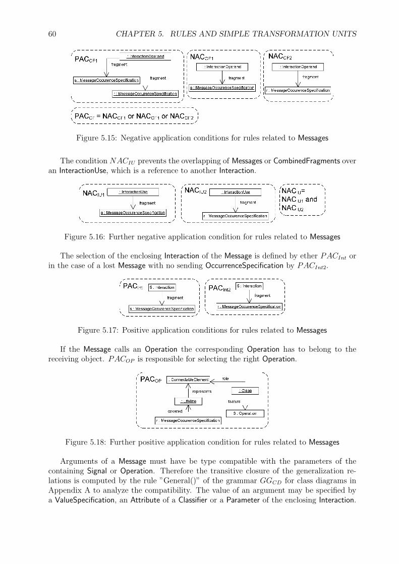
60 CHAPTER 5. RULES AND SIMPLE TRANSFORMATION UNITS
Figure 5.15: Negative application conditions for rules related to Messages
The condition NACIU prevents the overlapping of Messages or CombinedFragments overan InteractionUse, which is a reference to another Interaction.
Figure 5.16: Further negative application condition for rules related to Messages
The selection of the enclosing Interaction of the Message is defined by ether PACInt orin the case of a lost Message with no sending OccurrenceSpecification by PACInt2.
Figure 5.17: Positive application conditions for rules related to Messages
If the Message calls an Operation the corresponding Operation has to belong to thereceiving object. PACOP is responsible for selecting the right Operation.
Figure 5.18: Further positive application condition for rules related to Messages
Arguments of a Message must have be type compatible with the parameters of thecontaining Signal or Operation. Therefore the transitive closure of the generalization re-lations is computed by the rule ”General()” of the grammar GGCD for class diagrams inAppendix A to analyze the compatibility. The value of an argument may be specified bya ValueSpecification, an Attribute of a Classifier or a Parameter of the enclosing Interaction.

5.2. MESSAGES 61
The rule ”addArgument()” assigns one of these nodes as a new argument of the Message.NAC forbids arguments to be assigned to more than one value and PAC ensures thatthe parameter belongs to the Operation or Signal of the Message, the compatible typing ofthe parameter and the correct position of the argument according to the position of theparameter and selects the type of argument.
Figure 5.19: Rule addArgument()
The positive application conditions in Figure 5.20 select the parameter, to which thenew argument shall be assigned and they ensure a compatible typing relation betweenthe argument and the parameter. If it is an Argument of a Classifier the receiving Lifelineof the Message has to be connected to this Classifier. The case for a Parameter of anInteraction requires, that this Interaction has to own the Message and a constant is definedby a ValueSpecification.
Figure 5.20: Positive application conditions for the rule addArgument()

62 CHAPTER 5. RULES AND SIMPLE TRANSFORMATION UNITS
The complete insertion of arguments is defined by the transformation unit ”inser-tArgs()”, which inserts arguments and at the end checks, whether all arguments are as-signed. It may be the case, that there is no value to assign the arguments and this demands,that the Message can not be inserted.
Figure 5.21: Simple transformation unit insertArgs()
After inserting the arguments of a Message the rule ”checkPars()” verifies, that forall parameters of the corresponding Operation or Signal there is specified an argument.Therefore the transformation unit in Figure 5.21 applies this rule, which does not changethe graph but uses the application conditions PC1 and PC2 to execute this check.
Figure 5.22: Rule checkPars()
The application conditions PC1 and PC2 hold if for each Message all arguments areassigned. Therefore the premise P selects a parameter of the Operation or Signal belongingto the Message. For all these parameters the conclusion demands a argument at the Messagewith the same position in the order of the arguments.
Figure 5.23: Application conditions for the rule checkPars()
Some Messages send a Signal from one object to another. This Signal carries informationstored in its attribute and is created by ”insertSignal()” in Figure 5.24.

5.2. MESSAGES 63
Figure 5.24: Application conditions for the rule insertSignal()
The lifetime of an object can be specified by its creation point in time and its destructionpoint in time. They are defined by the corresponding Events and the OccurrenceSpecifi-cations for the point. The following two rules create these Events. While the negativeapplication condition NAC for the creation of an object demands, that the Occurrence-Specification ”1” has to be the first of the Lifeline, the condition for the DestructionEventrequires ”1” to be the last one.
Figure 5.25: Rule creatCreationEvent()
Figure 5.26: Rule creatDestruction()
Affected constraints, class: DestructionEvent
[1] No other OccurrenceSpecifications may appear below an OccurrenceSpecification whichreferences a DestructionEvent on a given Lifeline in an InteractionOperand.The NAC of the rule in Figure 5.26 forbids OccurrenceSpecifications beyond an destruc-tion and NAC3 for the rules ”addOS()” and ”addOSSynch()” forbids the insertion of anOccurrenceSpecification beyond a DestructionEvent.

64 CHAPTER 5. RULES AND SIMPLE TRANSFORMATION UNITS
The simplest content of a Message is a Signal, which is always sent asynchronously. Thiscontent is connected to the Message via the edge ”signature” and the Message leads fromthe sending OccurrenceSpecification to the receiving one. As Interactions are a compositionof their elements the Message is embedded into the enclosing Interaction. While insertingthe Message there are also created the corresponding sending and receiving Events. If theSignal has parameters the transformation unit calls the rule ”addArgs()” to assign for eachparameter an attribute of the Message. To complete the transformation the order structurehas to be updated by applying the rule ”order()” as long as possible. The applicationconditions ensure, that the sending object is not blocked by a synchronization, that thereceiving of the Message occurs not before it was sent, and that the Message does not leadfrom one operand to another of a CombinedFragment or inside of an InteractionUse.
Figure 5.27: Rule signal()
A more complex Message calls an Operation. If there are no further synchronizationrestrictions the rule of Figure 5.28 can be used to create this asynchronous Message. Asbefore the corresponding Events and arguments are created, the Message is connected tothe corresponding Operation and Interaction, and the ordering structure is updated. Theapplication conditions are nearly the same as in the rule ”signal()”, but additionally PAC3
ensures, that the receiving object understands the operation call as it has to own the calledOperation.

5.2. MESSAGES 65
Figure 5.28: Rule asynchronous()

66 CHAPTER 5. RULES AND SIMPLE TRANSFORMATION UNITS
An operation call may also be sent synchronously. The sender is not able to sendfurther Messages till he gets the reply of the operation call. Therefore a synchronizedarea is created at the end of a Lifeline. It can be extended by the rule in Figure 5.6 andfinished by the creation of a suitable reply as in Figure 5.30. The application conditionsdo not differ much from the preceding rule for the asynchronous case, except NAC5, whichadditionally demands the sending OccurrenceSpecification to be the last one on the Lifeline.Because of this condition there is no OccurrenceSpecification from which the object couldsend another Message after the just created one. It will be created by ”reply()”, whichcloses the synchronized area.
Figure 5.29: Rule synchronous()
Figure 5.30 defines the rule ”reply()”, which completes a synchronization, such thatthe sender of the corresponding synchronous Message has afterward the possibility to sendagain. Therefore the Message is connected with its Signal, the necessary arguments andEvents, and a new OccurrenceSpecification is generated at the end of the receiving Lifelineoutside of the synchronized area. The application conditions are the same as for the simplecase of sending a Signal.

5.2. MESSAGES 67
Figure 5.30: Rule createMessageReply()
The modeling of found and lost Messages is handled in the following figures from 5.31to 5.33. The first rule ”foundSignal()” creates the receiving of a found Signal, where aSignal event is generated as well as the necessary arguments, the Message is embedded intothe enclosing Interaction and the conditions select the corresponding Interaction and ensure,that the Message does not lead to an InteractionUse.

68 CHAPTER 5. RULES AND SIMPLE TRANSFORMATION UNITS
Figure 5.31: Rule createMessageFoundSignal()
Finding a synchronous call or an asynchronous call differs only in the Message attributeand is therefore handled in the one rule of Figure 5.32. The calling Event is created andthe Operation linked to the Message. As in the case of a Signal the conditions for therule select the correct Interaction and forbid, that the Message leads into an InteractionUse.Additionally PAC2 ensures, that the Operation is owned by the receiving object.
Figure 5.32: Rule createMessageFoundCall()
The last version of creating a found Message handles a reply, which is the sending of aSignal together with the completion of a synchronized area. Rule ”foundReply()” puts theMessage in context to the Signal and inside the enclosing Interaction. The receiving Eventis created and the condition PAC ensures, that the recipient is really waiting for a reply.

5.2. MESSAGES 69
Figure 5.33: Rule createMessageFoundReply()
Like a found Message has no sender a lost Message leads to no recipient. The rule”lostAsynchCall()” creates a lost Message, which sends an asynchronous operation call.Therefore the conditions ensure, that the sending object is not blocked by a synchronizationat this point and the Message is not created within an InteractionUse. PAC selects thecorrect Interaction and the necessary arguments are assigned by the transformation unit.
Figure 5.34: Rule createMessageLostAsynchCall()

70 CHAPTER 5. RULES AND SIMPLE TRANSFORMATION UNITS
Loosing a synchronous operation call is nearly the same as before, but this time thesender has to be blocked for sending. Therefore the additional condition NAC5 ensures,that the sending point is at the end of the Lifeline and the rule creates a node of the type”Synchronization”.
Figure 5.35: Rule createMessageLostSynchCall()
A lost reply is equal to a lost Signal and hence both need only the rule in Figure 5.36.The difference to Figure 5.34 is the connection to a Signal instead of the Operation andtherefore also the creation of the corresponding Event.
Figure 5.36: Rule createMessageLostSignal()

5.2. MESSAGES 71
Affected constraints, class: Message
[1] If the sending MessageEvent and the receiving MessageEvent of the same Messageare on the same Lifeline, the sending MessageEvent must be ordered before the receivingMessageEvent.The order edges ensure, that no Message can go backwards. Condition NACM preventswrong order edges.
[2] The signature must either refer an Operation (in which case messageSort is eithersynchCall or asynchCall) or a Signal (in which case messageSort is asynchSignal). Thename of the NamedElement referenced by signature must be the same as that of the Mes-sage. There are at all two cases for the creation of a Message. In the first case the Messageis connected to an Operation and in the second one to a Signal. The equality of the namesis handled by the same attribute values in the rules.
[3] In the case when the Message signature is an Operation, the arguments of the Mes-sage must correspond to the parameters of the Operation. A Parameter corresponds to anArgument if the Argument is of the same Class or a specialization of that of the Parameter.The rule ”insertArgs()” in Figure 5.21 creates the arguments for a Message and uses theedges of type ”general” to ensure the correct typing relation between the arguments andthe corresponding parameters.
[4] In the case when the Message signature is a Signal, the arguments of the Messagemust correspond to the attributes of the Signal. A Message Argument corresponds to aSignal Attribute if the Arguement is of the same Class or a specialization of that of theAttribute. The rule ”insertArgs()” from before handles also Signals.
[5] Arguments of a Message must only be:i) attributes of the sending lifelineii) constantsiii) symbolic values (which are wildcard values representing any legal value)iv) explicit parameters of the enclosing Interactionv) attributes of the class owning the InteractionThe rule ”addArgs()” covers attributes of the sending Lifeline, constants via ValueSpecifi-cations and parameters of the enclosing Interaction. Other arguments cannot be created.
[6] Messages cannot cross bounderies of CombinedFragments or their operands.The example in the UML specification in Figure 14.10 on page 456 shows a Message cross-ing the border of a CombinedFragment. This feature is explicitly wanted, such that theconstraint should only forbid a crossing between operands. The condition PACCF ensuresthis version of constraint [6] for creating Messages and NACM prevents CombinedFragmentsto be extended with an overlapping over an OccurrenceSpecification connected to a Message.
[7] If the MessageEnds are both OccurrenceSpecifications then the connector must go be-tween the Parts represented by the Lifelines of the two MessageEnds.The Connector is not modeled in LSD.

72 CHAPTER 5. RULES AND SIMPLE TRANSFORMATION UNITS
To specify directly an order relation between two OccurrenceSpecifications there is thenode type GeneralOrdering. The UML specifies no constraints, but there should not be aGeneralOrdering in the reversed direction of a Message. Cases like this are forbidden by thecondition NAC1. NAC2 just prevents more than one GeneralOrdering between the samenodes.
Figure 5.37: Rule generalOrdering()
5.3 Combined Fragments
CombinedFragments deliver the possibility to use controll structures like alternatives andloops. The different kinds are described in the previous section on page 48. The Interac-tionOperand has an additional attribute ”isPrimary”. It is used to decide between the firstand the other operands of a CombinedFragment. The rules, which extend the content ofthe first operand, use existing OccurrenceSpecifications and the other extension rules createnew ones. The secondary operands are not ordered semantically in sense of time after thefirst one and therefore the order edges do not go from one operand to another of the sameCombinedFragment.
The rules in Figure 5.38 and 5.39 create a new CombinedFragment, where the secondrule generates the special node type ”ConsiderIgnoreFragment”. Messages inside a Com-binedFragment have to be created after the enclosing CombinedFragment was created, butCombinedFragments inside of a CombinedFragment have to be created before.

5.3. COMBINED FRAGMENTS 73
Figure 5.38: Simple transformation unit insertCombinedFragment()
Figure 5.39: Simple transformation unit insertCombinedFragment()
As CombinedFragments include their fragments inside of operands the rule ”insertIn-tOpPri()” in Figure 5.40 places the first InteractionOperand into the CombinedFragment.
Figure 5.40: Rule insertIntOpPri()
Some kinds of CombinedFragments may have more than one operand. Therefore therule ”cF-extendIntOp()” creates a further operand for the CombinedFragment.
cF-extendIntOp()
LHS RHSo ∈ {alt, assert, consider, critical, ignore, par, seq, strict}
nameinteractionOperator
1 : CombinedFragment
2 : InteractionOperand
nameinteractionOperator
1 : CombinedFragment
2 : InteractionOperand
operand operand
operand
nameisPrimary = false
: InteractionOperandend
end
560279840
Figure 5.41: Rule cF-extendIntOp()

74 CHAPTER 5. RULES AND SIMPLE TRANSFORMATION UNITS
Affected constraints, class: CombinedFragment
[1] If the interactionOperator is opt, loop, break, or neg there must be exactly one operand.The cases above are respected by the variable ”o”, which is not allowed to be assigned tothe mentioned values in the rule ”cF-extendOp()” for adding an additional operand to aCombinedFragment.
[3] If the interactionOperator is break, the corresponding InteractionOperand must coverall Lifelines within the enclosing InteractionFragment.This operator is not included in the grammar by now.
[4] The interaction operators ’consider’ and ’ignore’ can only be used for the Combine-IgnoreFragment subtype of CombinedFragment.((interactionOperator = #consider) or (interactionOperator =#ignore)) implies oclisTypeOf(CombineIgnoreFragment)This case is handled separately by the rule ”insertCombinedFragmentCI()”.
Affected constraints, class: ConsiderIgnoreFragment
[1] The interaction operator of a ConsiderIgnoreFragment must be either consider or ig-nore.(interactionOperator = #consider) or (interactionOperator = #ignore)As mentioned before, the rule ”insertCombinedFragmentCI()” creates a ConsiderIgnore-Fragment with the appropriate attribute value.
[2] The NamedElements must be of a type of element that identifies a message (e.g., anOperation, Reception, or a Signal).message-¿forAll(m — m.oclIsKindOf(Operation) or m.oclIsKindOf(Reception) or m.oclIsKindOf(Signal))The rules, which create Messages, only connect Operations and Signals.
Affected constraints, class: InteractionOperand
[1] The guard must be placed directly prior to (above) the EventOccurrence that will becomethe first EventOccurrence within this InteractionOperand.This constraint is only visual and therefore does not restrict the abstract syntax.
The rule ”cF-startOS()” puts the first InteractionFragment into the CombinedFragment.This first fragment is of the type ”OccurrenceSpecification”. The first condition requires,that the primary operand of the CombinedFragment is empty and the second forbids, thatthe OccurrenceSpecification ”2” is already owned by another CombinedFragment. NAC3
forbids Messages to be connected to ”2” and NAC4 forbids ”2” to be owned by an Inter-actionUse. They are defined in Figure 5.43. Thus at all the OccurrenceSpecification ”2”has to be totally free and in general it is required that an OccurrenceSpecification can onlybe owned directly by at most one CombinedFragment and also at most one operand of aCombinedFragment.

5.3. COMBINED FRAGMENTS 75
Figure 5.42: Rule cF-startOS()
Figure 5.43: NACs for rules for InteractionOperands

76 CHAPTER 5. RULES AND SIMPLE TRANSFORMATION UNITS
In Figure 5.44 is defined the rule ”iO-extendPriV()”, which extends an interactionoperand vertically, which means along a Lifeline. The new fragment is an OccurrenceSpec-ification and the edge, which indicates the end of the operand on the Lifeline is updatedto this new OccurrenceSpecification. The condition PAC ensures, that there is at leastone succeeding OccurrenceSpecification after ”2”, which is necessary to add more Occur-renceSpecifications afterward. NAC1 forbids another operand of a CombinedFragment tobe connected to the OccurrenceSpecification ”2”. The other conditions forbid crossing Mes-sages and an already existing ownership by an InteractionUse.
Figure 5.44: Simple transformation unit iO-extendPriV()
The difference for extending a secondary interaction operand of a CombinedFragmentto a primary is based on the ordering structure between these operands. An edge ofthe type order shall not exist between operands of a CombinedFragment, as there is ingeneral no sequential dependency. Therefore a new OccurrenceSpecification is created forextending a secondary operand. It has to be connected by order edges to all other Oc-currenceSpecifications of the same Lifeline, which are outside of the CombinedFragment. Asbefore in Figure 5.44 the condition NAC ensures that the OccurrenceSpecification ”3” isnot already connected to another CombinedFragment. PAC1 regulates that only the lastinserted interaction operand of a CombinedFragment can be extended. Otherwise it wouldbe possible with the rules in Figures 5.46 to 5.47 to create operands which cover Occur-renceSpecifications before and after another one on the same Lifeline, which would causesequential dependency. This way of directed editing corresponds to the extension of aprimary operand, which can not be extended on a Lifeline, if there is already a secondaryoperand present on this Lifeline.

5.3. COMBINED FRAGMENTS 77
Figure 5.45: Simple transformation unit iO-extendSecV()
The extension of a CombinedFragment with OccurrenceSpecifications of a Lifeline, whichwas not included before, is managed by the simple transformation units for horizontalextension ”iO-extendPriH()” and ”iO-extendSecH()”. NAC1 and NAC2 for the rule ”iO-extendPriHStart()” in Figure 5.46 demand the Lifeline ”3” to be not connected to theCombinedFragment via an OccurrenceSpecification. NAC3 ensures, that there is no Messageending at the OccurrenceSpecification ”2” and NAC4 that no InteractionUse owns it.

78 CHAPTER 5. RULES AND SIMPLE TRANSFORMATION UNITS
Figure 5.46: Simple transformation unit iO-extendPriH()
The horizontal extension of a secondary operand ”4” of a CombinedFragment creates anew OccurrenceSpecification on a Lifeline, which is not connected with the CombinedFrag-ment. The independence of the Lifeline ”6” toward the operand ”4” is expressed in thecondition NAC1. NAC2 demands the OccurrenceSpecification ”3” to be not connected toanother CombinedFragment. This restriction ensures, that the ordering structure to suc-ceeding operands is retained. Otherwise there would be no order edge between the newOccurrenceSpecification and succeeding secondary operands of the other CombinedFragment.PAC1 claims the OccurrenceSpecification ”1” to be the predecessor of all OccurrenceSpec-ifications of the CombinedFragment, which will be extended. The other positive conditionPAC2 says, that the OccurrenceSpecification ”2”, which will be the predecessor of the newone, is owned by the CombinedFragment, but not via the operand to extend.

5.3. COMBINED FRAGMENTS 79
Figure 5.47: Simple transformation unit iO-extendSecH()
Apart from OccurrenceSpecifications a CombinedFragment may contain other Combined-Fragments. The rule ”iO-extendCFStart” in Figure 5.48 describes the first step of includinga CombinedFragment into another one. The interaction operand of the outer Combined-Fragment ends at an OccurrenceSpecification before the new inner CombinedFragment ”4”.After the extension the inner CombinedFragment ”4” is a fragment of the outer one andthe operand of the outer one also includes the OccurrenceSpecification succeeding the innerCombinedFragment. The conditions referenced in PC are defined in Figure 5.50.

80 CHAPTER 5. RULES AND SIMPLE TRANSFORMATION UNITS
Figure 5.48: Rule iO-extendCFStart()
After inserting the first part of the inner CombinedFragment into the outer one the edge”fragment” between them has not to be created again for extending the inclusion to theleft Lifelines of the inner CombinedFragment ”4”. Therefore the rule ”iO-extendCFStep()”differs only in this added edge toward ”iO-extendCFStart()” and is applied as long aspossible in the transformation unit of Figure 5.51 to complete the inclusion.
Figure 5.49: Rule iO-extendCFStep()
The conditions for the rules extending a CombinedFragment by another one are shownin Figure 5.50. PCExtendCFLifeline forbids a Lifeline, which is connected to the innerCombinedFragment ”4” but not to the outer interaction operand ”1”. For this reason theinclusion will cover all demanded Lifelines. The two positive application conditions PAC1
and PAC2 ensure that the OccurrenceSpecifications ”2” and ”3” are situated directly beforerespectively after the inner CombinedFragment ”4” on the Lifeline. To prevent, that acommon Lifeline of the inner CombinedFragment and the outer operand is not included,the condition NAC1 forbids an additional OccurrenceSpecification on any common Lifelinebetween the operand and the inner operand. This condition is only necessary to be checkedonce per inclusion, thus it could be deleted for the rule ”iO-extendCFStep()”. The lefte

5.3. COMBINED FRAGMENTS 81
conditions NACM and NACIU forbid a Message or InteractionUse to be connected to onof the two surrounding OccurrenceSpecifications ”2” and ”3”.
Figure 5.50: Conditions for rules extending CombinedFragments by other ones
Including a CombinedFragment into another one is managed by the transformation unit”iO-extenndCF()” in Figure 5.51. After connecting the inner CombinedFragment to theouter operand all parts of covered Lifelines of the inner CombinedFragment are inserted.There may be some order edges to much between other operands of the outer Combined-Fragment, which have to be deleted by ”deleteWrongOrder()” in Figure 5.52 at the end.
Figure 5.51: Simple transformation unit iO-extendCF()

82 CHAPTER 5. RULES AND SIMPLE TRANSFORMATION UNITS
The previous figure described a transformation unit for inserting a CombinedFragmentinto the operand of another one. As there may be other operands of the outer Combined-Fragment some order edges have to be deleted, which connect its operands. The conditionNAC forbids the unification of both operands ”1” and ”3”, thus order edges in one operandare not deleted.
Figure 5.52: Rule interactionOperandDeleteWrongOrder()
5.4 Constraints
Restrictions for the possible semantic traces of an interaction can be defined by Constraintsfor CombinedFragments. The language Visual OCL contains visualized OCL constraints,which can be generated by the graph grammar GGV OCL defined in [17]. Beside VOCLsimple constraints can be defined by an expression included in a node of the type Value-Specification. Constraints can be connected to interaction operands of CombinedFragmentseither via the rule ”cF-constraint()” or ”cf-constraintValSpec()” and they can specify forinstance the conditions under which the operands are chosen.
Figure 5.53: Rule cF-constraint()
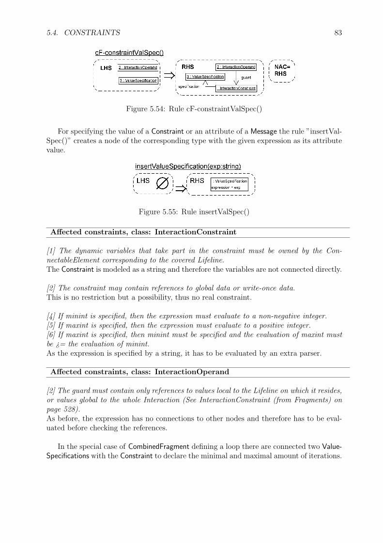
5.4. CONSTRAINTS 83
Figure 5.54: Rule cF-constraintValSpec()
For specifying the value of a Constraint or an attribute of a Message the rule ”insertVal-Spec()” creates a node of the corresponding type with the given expression as its attributevalue.
Figure 5.55: Rule insertValSpec()
Affected constraints, class: InteractionConstraint
[1] The dynamic variables that take part in the constraint must be owned by the Con-nectableElement corresponding to the covered Lifeline.The Constraint is modeled as a string and therefore the variables are not connected directly.
[2] The constraint may contain references to global data or write-once data.This is no restriction but a possibility, thus no real constraint.
[4] If minint is specified, then the expression must evaluate to a non-negative integer.[5] If maxint is specified, then the expression must evaluate to a positive integer.[6] If maxint is specified, then minint must be specified and the evaluation of maxint mustbe ¿= the evaluation of minint.As the expression is specified by a string, it has to be evaluated by an extra parser.
Affected constraints, class: InteractionOperand
[2] The guard must contain only references to values local to the Lifeline on which it resides,or values global to the whole Interaction (See InteractionConstraint (from Fragments) onpage 528).As before, the expression has no connections to other nodes and therefore has to be eval-uated before checking the references.
In the special case of CombinedFragment defining a loop there are connected two Value-Specifications with the Constraint to declare the minimal and maximal amount of iterations.

84 CHAPTER 5. RULES AND SIMPLE TRANSFORMATION UNITS
Figure 5.56: Rule createLoopCF()
Affected constraints, class: CombinedFragment
[2] The InteractionConstraint with minint and maxint only apply when attached to anInteractionOperand where the interactionOperator is loop.There is only the previous rule, which creates a connection to minimum and maximumvalues and this rule fulfills the constraint.
Affected constraints, class: InteractionConstraint
[3] Minint/maxint can only be present if the InteractionConstraint is associated with theoperand of a loop CombinedFragment.This constraint says the same as before.
5.5 Interaction Use
Hierarchical structures of whole Interactions are created by InteractionUses. The conditionsfor the rules, which create and extend an InteractionUse are defined in Figure 5.57, wherePACIntUse demands, that common Lifelines of a referenced Interaction have to be in the en-closing Interaction. The negative application conditions prevent, that a CombinedFragmentor a Message is connected to the OccurrenceSpecification ”2”, which shall be included inthe InteractionUse.
The first step of creating an InteractionUse is handled by the rule ”interactionUseCre-ate()” in Figure 5.58, which connects it on the one hand with the referenced Interactionand on the other hand with an OccurrenceSpecification of the enclosing Interaction. As theInteractionUse is an InteractionFragment it has to be included in the outer Interaction at theend. The conditions ensure, that the OccurrenceSpecification is not connected to a Messageor a CombinedFragment, but to the outer Interaction.

5.5. INTERACTION USE 85
Figure 5.57: Conditions for rules in connection to InteractionUses
Figure 5.58: Rule interactionUseCreate()
Arguments of an InteractionUse may be parameters of the enclosing Interaction andconstants. They are created by the simple transformation unit in Figure 5.60. The nextfigure shows conditions used by the rules of this unit. PACT1 and PACT2 ensure the correcttyping of the inserted argument and PACP ensures, that the referenced Interaction has aparameter at the used position. NACA ensures, that this position is not assigned already.If PACPI holds, that a Parameter of the enclosing Interaction is selected as argument andin the other case PACV S demands a ValueSpecifiaction to use a constant.
The simple transformation unit ”addArgument-IU()” inserts an argument for an Inter-actionUse in form of a ValueSpecification defining a constant or a Parameter of the enclosingInteraction.

86 CHAPTER 5. RULES AND SIMPLE TRANSFORMATION UNITS
Figure 5.59: Conditions for inserting an argument for an InteractionUse
Figure 5.60: Simple transformation unit insertArgs-IU()
Extending an InteractionUse is divided into two direction. The rule ”interactionUse-ExtendH()” adds a new OccurrenceSpecification in horizontal direction meaning that theOccurrenceSpecification belongs to a Lifeline, which was not covered by the InteractionUsebefore. The positive application condition PAC demands, that the new Lifeline has to occuralready in the referenced Interaction. NAC2 forbids an already existing connection of theInteractionUse with the Lifeline of the new OccurrenceSpecification and NAC1 ensures, thatno Message nor CombinedFragment is connected to the new OccurrenceSpecification. ”in-teractionUseExtendHNeeded()” extends an InteractionUse horizontally as long as it has tobe, becaus there are common Lifelines between the referenced Interaction and the enclosingone, which are not covered.
Figure 5.61: Rule interactionUseExtendH()

5.5. INTERACTION USE 87
The extra condition PAC2 selects a Lifeline, that is common between the Interactionreferenced by the InteractionUse and the enclosing Interaction to cover this Lifeline. This isdemanded by the UML specification.
Figure 5.62: Rule interactionUseExtendHNeeded()
Extending an InteractionUse vertically as in Figure 5.63 means to extend it by oneOccurrenceSpecification on a Lifeline, which is already covered. As before the applicationcondition NAC1 demands the new OccurrenceSpecification to be not used by Messages orCombinedFragments.
Figure 5.63: Rule interactionUseExtendV()
The last step for creating an InteractionUse is to test, if all necessary Lifelines are covered.Therefore the rule ”interactionUseTest()” checks whether each InteractionUse is complete.The rule performs no changing of the graph. But its application condition PC2 ensuresthat common Lifelines of at least two InteractionUses in the same Interaction have to beintegrated in the enclosing Interaction. PC1 ensures, that all parameters of the referenceInteraction are assigned with a value.

88 CHAPTER 5. RULES AND SIMPLE TRANSFORMATION UNITS
Figure 5.64: Rule interactionUseTest()
Affected constraints, class: InteractionUse
[1] Actual of the InteractionUse must match Formal Gates of the referred Interaction.Gates match when their names are equal.This condition is checked via PAC of the rule ”insertActualGate()”.
[2] The InteractionUse must cover all Lifelines of the enclosing Interaction which appearwithin the referred Interaction.The rule ”interactionUseTest()” ensures that a Lifeline of the enclosing Interaction has tobe covered by the InteractionUse if it is connected to a role common with the referencedInteraction.
[3] The arguments of the InteractionUse must correspond to parameters of the referred In-teraction.Arguments of InteractionUses are typed according to the parameters of the referenced Inter-action because of PACT1 and PACT2 in Figure 5.59. The attribute ”order” of the argumentedge defines the connection to the parameter.
[4] The arguments must only be constants, parameters of the enclosing Interaction or at-tributes of the classifier owning the enclosing Interaction.The rules ”addArgumentPar-IU()” and ”addArgument-IU()” connect a parameter of theenclosing Interaction or a ValueSpecification as an argument to the InteractionUse. Otherargument can not be created.
Affected constraints, class: Lifeline
[1] If two (or more) InteractionUses within one Interaction, refer to Interactions withcommon Lifelines, those Lifelines must also appear in the Interaction with the Interac-tionUses. By common Lifelines we mean Lifelines with the same selector and representsassociations.The condition PC2 of ”interactionUseTest()” covers exactly this constraint and new Life-lines can only be created by ”createLifeline()”, if no InteractionUse is connected to theenclosing Interaction.

5.5. INTERACTION USE 89
Figure 5.65: Rule interactionUse()
Combining the previous rules leads to the transformation unit ”interactionUse()” inFigure 5.65, which creates an InteractionUse.
Gates deliver the anchor points for Messages at the border of an InteractionUse or anInteraction. In the first case they are called actual Gates and their name shall correspondto the Message and its direction.
Figure 5.66: Rule insertActualGate()
Connection points for Messages coming from or going outside of the Interaction arecalled formal Gates and can be created by ”insertFormalGate()” in Figure 5.67. The nameof a formal Gate of an Interaction and an actual Gate of an InteractionUse have to be equalto merge them together, such that the whole Message can be composed of the one in theInteraction and the corresponding one of the InteractionUse.
Figure 5.67: Rule insertFormalGate()
An Message carrying an operation call may com from outside of an Interaction. Therule ”messageCallGateInt()” generates this Message with the corresponding Event, whichcalls the Operation. As the sender is not known in this context a synchronous Messageand an asynchronous Message do only differ in its attribute value of MessageSort. Usedconditions for Messages at actual and formal Gate are defined in Subsection 5.2 for generalMessages. NAC1 and NAC2 forbid the receiving OccurrenceSpecification to be covered byan InteractionUse or a CombinedFragment, PAC1 ensures, that the recipient owns the calledOperation and PAC2, that the used Interaction owns the receiving OccurrenceSpecification.At the end all necessary arguments of the Message are assigned by ”insertArgs()”.

90 CHAPTER 5. RULES AND SIMPLE TRANSFORMATION UNITS
Figure 5.68: Simple transformation unit messageCallGateInt()
The difference between sending a Signal and an operation call from a formal Gateinto an Interaction is naturally the content and the created Event type. Therefore therule ”messageSignalGateInt()” has only these differences in comparison to the latter ruleincluding the loss of the Operation specific condition PACOP .
Figure 5.69: Simple transformation unit messageSignalGateInt()
A Message coming from an Interaction and going outside via a formal Gate is generatedby the following three rules. For sending a Signal, the Message and the sending Event arecreated in Figure 5.70. PAC1 selects the correct Interaction and the negative applicationconditions forbid the sending OccurrenceSpecification to be owned by a CombinedFragmentor an InteractionUse and to be blocked by a synchronized area.

5.5. INTERACTION USE 91
Figure 5.70: Simple transformation unit messageSignal-IntGate()
Sending an operation call from an Interaction to its formal Gate is defined in rule”messageAsynchCall-IntGate()” in Figure 5.71. As before the Message and its correspond-ing sending Event are created and connected to the appropriate elements. The conditionsare exactly the same.
Figure 5.71: Simple transformation unit messageAsynchCall-IntGate()
For an synchronous Message there is one extension, apart from the difference in theattribute MessageSort. The sender is blocked, to send any other Message after this Messagewas send and until a appropriate reply is received. Therefore the rule in Figure 5.72creates a node of the type ”Synchronization” and ensures via NAC3, that the sendingOccurrenceSpecification is at the end of the Lifeline.

92 CHAPTER 5. RULES AND SIMPLE TRANSFORMATION UNITS
Figure 5.72: Simple transformation unit messageSynchCall-IntGate()
Messages going from inside an InteractionUse to an outgoing actual Gate are created bythe next three rules. An asynchronous operation call is send in Figure 5.73. The sendingEvent is created and the Message is connected to the enclosing Interaction and the Operation,which shall be called. Like the rule for asynchronous Messages between Lifelines, this rulehas conditions, which forbid the sender to be blocked because of a synchronized area, whichensure the correct ordering structure to the other Messages, and which forbid, that theMessageEnds are parts of a CombinedFragment. PACGate selects the before created Messagefrom the corresponding formal Gate of an Interaction to one of its OccurrenceSpecifications.The attributes of this Message are copied into the new one and its Operation is connectedto the new Message. PACOP ensures, that the recipient owns the Operation, which shall becalled and NACIU2 finally forbids the receiving OccurrenceSpecification to be itself coveredby an InteractionUse.

5.5. INTERACTION USE 93
Figure 5.73: Simple transformation unit messageAsynchCall-IUGate()
Figure 5.74: Positive application condition for rules concerning gates
The creation of a synchronous Message from an InteractionUse to an actual Gate isdefined by the rule ”messageSynchCall-IUGate()” and differs from the previous rule forasynchronous Messages by the insertion of a synchronized area at the last MessageEnd ofthe sending Lifeline, where the Message is send from.

94 CHAPTER 5. RULES AND SIMPLE TRANSFORMATION UNITS
Figure 5.75: Simple transformation unit messageSynchCall-IUGate()
An easier case for Messages is the transport of a Signal. ”messageSignal-IUGate()” inFigure 5.75 defines the rule for creating a Message sending a Signal from an InteractionUseto one of its actual Gates. The process is the same as above for sending an operation calland therefore the corresponding Message from the merged formal Gate to the Interaction,referenced by the InteractionUse, has to be created before this rule can be applied. Andnaturally this Message is connected to a Signal and not synchronized.
Figure 5.76: Simple transformation unit messageSignal-IUGate()

5.5. INTERACTION USE 95
The other direction for a Message inside of an InteractionUse is from an actual Gate to acovered Lifeline. The rule in Figure 5.77 creates this Message as well as the correspondingreceiving Event and connects them to the appropriate elements. For applying this rule aMessage m2 from the corresponding formal Gate of an Interaction to a Lifeline of this Inter-action has to be existent already. The conditions NAC1, NAC2 and PAC1 ensure, thatthe new Message is not send backwards or through the border of operands of a Combined-Fragment and that the sending OccurrenceSpecification is not owned by an InteractionUse.PAC2 and PAC3 select the correct Interaction and Operation and PACGate2 the Messagem2 and copies its attribute values.
Figure 5.77: Simple transformation unit messageCallGateIU()
Figure 5.78: Further positive application condition for rules concerning gates
A Message carrying a Signal into an InteractionUse is created by ”messageSignalGateIU()”.The rule differs from the one before only in the content of the Message and the decreasedamount of conditions, because there is no Operation in this context.
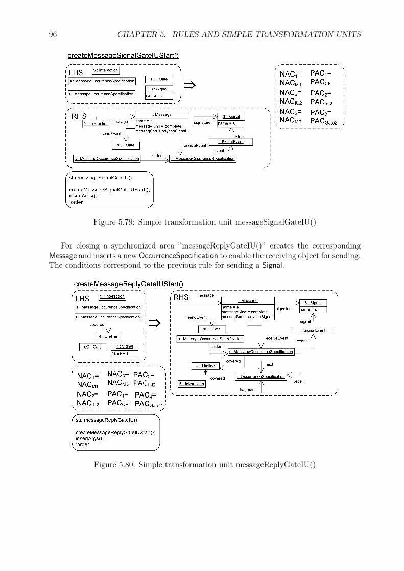
96 CHAPTER 5. RULES AND SIMPLE TRANSFORMATION UNITS
Figure 5.79: Simple transformation unit messageSignalGateIU()
For closing a synchronized area ”messageReplyGateIU()” creates the correspondingMessage and inserts a new OccurrenceSpecification to enable the receiving object for sending.The conditions correspond to the previous rule for sending a Signal.
Figure 5.80: Simple transformation unit messageReplyGateIU()

5.6. LIST OF SIMPLE TRANSFORMATION UNITS 97
Affected constraints, class: Gate
[1] The message leading to/from an actualGate of an InteractionUse must correspond tothe message leading from/to the formal Gate with the same name of the Interaction refer-enced by the InteractionUse.Messages insides of InteractionUses are created by checking the correspondence of the nameand signature using the condition PACGate or PACGate2.
[2] The message leading to/from an (expression) Gate within a CombinedFragment mustcorrespond to the message leading from/to the CombinedFragment on its outside.There are no Gates within a CombinedFragment in LSD.
5.6 List of Simple Transformation Units
The following table constitutes all simple transformation units, which can be applied to agraph of LSD to gain another one of LSD. Some elements of the list have names of rules.Such a name represents a simple transformation unit, which contains only the referencedrule.
Table 5.1: Simple Transformation Units of GGSD.
Part Simple Transformation Units PageBasic Elements createInteraction(iName:string) 53
addParameterInt(name:string,pKind:PKindEnum)
54
createLifeline(objectName:string) 54addOS() 55addOSSynch() 56createStateInvariant() 57insertActionExecutionSpecification() 57insertBehaviorExecutionSpecification() 58insertAction() 59
Messages insertArgs() 62insertSignal(nameS:string) 63createCreationEvent() 63creatDestructionEvent() 63signal() 64asynchronous() 65synchronous() 66reply() 67foundSignal() 68foundCall(s:MessageSort) 68foundReply() 69lostAsynchCall() 69
Continued on next page

98 CHAPTER 5. RULES AND SIMPLE TRANSFORMATION UNITS
Table 5.1 – continued from previous pagePart Simple Transformation Units Page
lostSynchCall() 70lostSignal() 70generalOrdering() 72
CombinedFragments createCombinedFragment() 73createConsiderIgnoreFragment() 73cf-ExtendIntOp() 73cF-startOS() 75iO-extendPriV() 76iO-extendSecV() 77iO-extendPriH() 78iO-extendSecH() 79iO-extendCF() 81
Constraints cF-constraint() 82cF-constraintValSpec() 83insertValueSpecification(exp:string) 83cF-loop() 84
Interaction Uses interactionUse() 89insertActualGate() 89insertFormalGate(nameG:string) 89messageCallGateInt(kind:MessageSort) 90messageSignalGateInt() 90messageSignal-IntGate() 91messageAsynchCall-IntGate() 91messageSynchCall-IntGate() 92messageAsynchCall-IUGate() 93messageAsynchCall-IUGate() 94messageSignal-IUGate() 94messageCallGateIU() 95messageSignalGateIU() 96messageReplyGateIU() 96
After defining the abstract syntax of Sequence Diagrams in this part, the next part”Validation and Conclusion” will show how the definition can be used and it also showsthat there is a direct correspondence between diagrams defined with GGSD and UMLSequence Diagrams.

Part III
Validation and Conclusion
99


101
The abstract syntax of Sequence Diagrams is defined in Part II and strongly correspondsto the definition of UML Sequence Diagrams. Figure 5.81 describes the content of Chapter6 and Chapter 7. As the rules of the graph grammar GGSD for LSD follow the UMLconstraints, as argued at each rule in Chapter 5, the model transformation from a SequenceDiagram of LSD to the corresponding Sequence Diagram in UML syntax is simple andshort. Whereas the reverse way is much more complex. This direction is sketched by someselected examples, which contain the main features of Sequence Diagrams. They can begenerated by GGSD as described in Chapter 7.
Figure 5.81: Overview of Part III
At the end of this part Chapter 8 suggests how the the formal definition of SequenceDiagrams can be used to gain practical benefits. An UML instance describes a model bya selection of different diagram techniques. Just one view of these models is taken byobserving the Sequence Diagrams of the collection. Taking into account that all diagramscan be more or less strongly connected to each other there may exist failures because ofan inconsistent labeling or redefined parts. Those errors can be avoided or recognized bygenerating the diagrams via the graph grammar GGUML which contains of course GGSD
but also grammars defined in other papers like GGSM = SMGG for State Machines in [12]or GGCD mainly defined in [17] but redefined in Appendix A.
Editing a diagram via the rules of a graph grammar is not the natural process for adeveloper, thus he would like to have a visual editor, which uses the rules of the grammar,but allows him to edit the diagram in concrete syntax. Therefore the ”TIGER” project [2]of the research group TFS at the Technical University of Berlin shall provide a designer tospecify the grammar and a generator, which automatically creates an editor for the visuallanguage. This editor is developed and will be integrated in Eclipse and its componentsare described in Chapter 8.

102
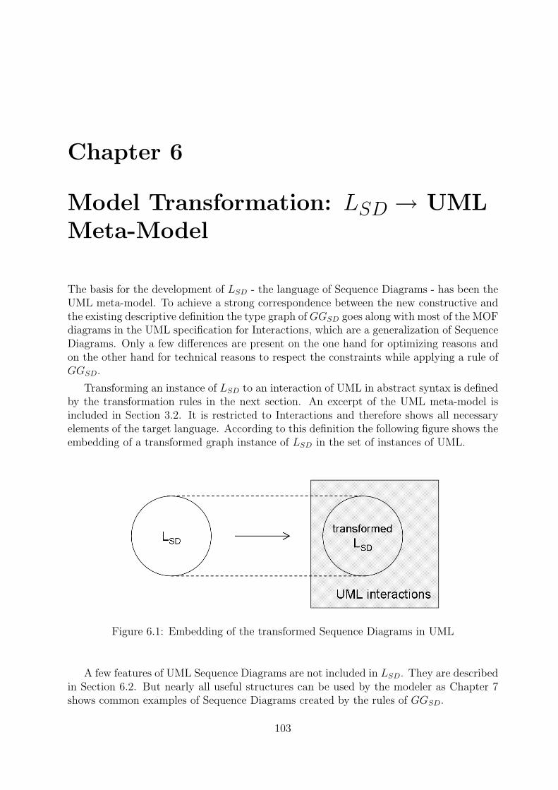
Chapter 6
Model Transformation: LSD → UMLMeta-Model
The basis for the development of LSD - the language of Sequence Diagrams - has been theUML meta-model. To achieve a strong correspondence between the new constructive andthe existing descriptive definition the type graph of GGSD goes along with most of the MOFdiagrams in the UML specification for Interactions, which are a generalization of SequenceDiagrams. Only a few differences are present on the one hand for optimizing reasons andon the other hand for technical reasons to respect the constraints while applying a rule ofGGSD.
Transforming an instance of LSD to an interaction of UML in abstract syntax is definedby the transformation rules in the next section. An excerpt of the UML meta-model isincluded in Section 3.2. It is restricted to Interactions and therefore shows all necessaryelements of the target language. According to this definition the following figure shows theembedding of a transformed graph instance of LSD in the set of instances of UML.
Figure 6.1: Embedding of the transformed Sequence Diagrams in UML
A few features of UML Sequence Diagrams are not included in LSD. They are describedin Section 6.2. But nearly all useful structures can be used by the modeler as Chapter 7shows common examples of Sequence Diagrams created by the rules of GGSD.
103

104 CHAPTER 6. MODEL TRANSFORMATION: LSD → UML META-MODEL
6.1 Model Transformation
Instances of LSD define interactions of UML. They strongly regard its abstract syntaxsuch that a transformation to UML consists only by some simple rules. These either deletesome technical edges needed for the control of the editing process or they add edges togain bidirectional navigation possibilities out of one connecting edge.
Figure 6.2 describes also the changing conditions for the typing of an instance beforeand after the transformation. At the beginning a Sequence Diagram is typed over TGUML
or more precisely over TGSD. During the transformation process the type graph changesto the integrated version TG′
UML, which includes TGUML as well as all new needed edgetypes gained out of the UML meta-model. At the end of the transformation the graphhas to be an instance of the UML meta-model and also has to follow all constraints. Asargued in Chapter 5 the constraints are respected and remain valid as only nodes andedges, not present in the UML meta-model, are deleted and the new edges are just copiesof the existing ones except of the new direction and name.
Figure 6.2: Model transformation from LSD to UML
New elements of the integrated type graph TG′UML are the edges shown in Figure 6.3.
All nodes and edges of TGUML remain in this new graph.
Figure 6.3: Additional edges in the integrated type graph TG′UML
The model transformation from LSD to UML starts with the deletion of the technicaledges and nodes by the rule ”deleteElements()”. The edges are necessary for the graphgrammar to restrict the insertion of new Messages. Only those are allowed, which do notviolate the ordering structure. But also nodes are deleted during the transformation. Theones of the type Synchronization define synchronized areas for blocking an object of a Lifelineto send Messages. These nodes and their connecting edges do not exist in the abstract
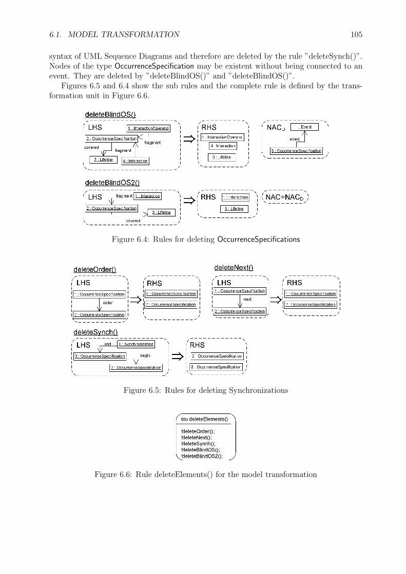
6.1. MODEL TRANSFORMATION 105
syntax of UML Sequence Diagrams and therefore are deleted by the rule ”deleteSynch()”.Nodes of the type OccurrenceSpecification may be existent without being connected to anevent. They are deleted by ”deleteBlindOS()” and ”deleteBlindOS()”.
Figures 6.5 and 6.4 show the sub rules and the complete rule is defined by the trans-formation unit in Figure 6.6.
Figure 6.4: Rules for deleting OccurrenceSpecifications
Figure 6.5: Rules for deleting Synchronizations
Figure 6.6: Rule deleteElements() for the model transformation

106 CHAPTER 6. MODEL TRANSFORMATION: LSD → UML META-MODEL
After deleting all nodes and edges, which are not present in the UML abstract syntax,some edges have to be added. They allow to navigate in the opposite direction betweennodes in the instance graph. Figures 6.7 and 6.8 define the rule ”addEdges()”, which addsall necessary edges.
Figure 6.7: Some rules for adding edges
Figure 6.8: Rules for addEdges()
Figure 6.9: Rule for addEdges()

6.1. MODEL TRANSFORMATION 107
Figure 6.10: Rule addEdges()
The transformation from LSD to UML is complete after applying ”addEdges()” and”deleteElements()”. Its simplicity is based on the strict conformance of the grammarGGSD to the MOF definition of UML for interactions. Termination is guaranteed, as therules for adding edges can be applied only once per match and the deleting rules deleteelements of finite sets. Elements for adding and for deleting are disjoint. Therefore themodel transformation can always be performed.
Figure 6.11 shows a small example of a model transformation to the UML meta-model.It models an interaction of two objects. A Message is send by the object of the left Lifelineand received by the one of the right Lifeline. The transformation adds the missing edgesfor bidirectional navigation: ”interaction”, ”message”, and ”coveredBy”.
Figure 6.11: Example of a model transformation to UML

108 CHAPTER 6. MODEL TRANSFORMATION: LSD → UML META-MODEL
6.2 Restrictions
LSD does not cover all features of UML Sequence Diagrams till now, but nearly all, whichare interesting and common for developing systems. The restrictions consist of the followingnode types and associations:
Nodes:
• A Continuation allows to define points in a Sequence Diagram, where another Se-quence Diagram follows. So the second diagram has some start points which aremerged to the ending points of the first diagram.
• The InteractionOperand ”break” of a CombinedFragment allows to define a cancellationof the Interaction of the enclosing InteractionFragment. If its guard is satisfied thecontent of the break block is processed and everything of the enclosing block isignored. As this CombinedFragment has to cover all Lifelines of the outer fragmentmany rules of GGSD have to be extended to ensure an updating of the break blockafter an alteration of the outer block.
• Time- and DurationConstraints belong to common behaviors and they specify thepoint in time or the duration of the sending or receiving of a Message in Interactions.Therefore they should be connected to the ends of a Message, but the UML onlyrestricts the Constraint to be linked to nodes of the type ”Element”.
• A PartDecomposition is a specialization of an InteractionUse to define the internalstructure of a Lifeline. It links the ConnectableElement of the Lifeline with an extraInteraction, which needs to contain all CombinedFragments, InteractionUses, and Oc-currenceSpecifications, which cover the Lifeline, as copies. Therefore all changes in theoriginal Interaction would cause updates of the copies by updating rules.
• Some special Messages can not be created by GGSD. They are lost or found Messagesat the borders of InteractionUses and they are normally not used. But they could begenerated by defining 10 more rules. Alternatively the rules for creating Messagesprobably can be optimized by using more transformation units to divide the creatingsteps in smaller rules. By using this optimized version the rare used message types,mentioned above, could be integrated more easily.
Associations:
• The selector of a Lifeline defines the element, which shall be described by the SequenceDiagram, if the connected element is multivalued, like an array.
• Connectors define links between ConnectableElements. They specify the references ofthe objects, which are communicating at runtime via Messages.
These missing parts will be defined in the future together with the other grammars,which are in progress to deliver an integrated grammar GGUML for most of the UMLdiagram techniques. Apart from the mentioned restrictions some instances of SequenceDiagrams are explicitly forbidden in LSD. They have a contradictory ordering structure,as a GeneralOrdering can be placed wherever a developer wants, even if it is in the oppositedirection of a sequence of Messages. This leads to a model, which can not be implemented.

Chapter 7
Validation of the Graph Grammar byBenchmarks
The first step of the validation of the grammar GGSD was done in Chapter 5 by the argu-mentation for each simple transformation unit to satisfy the corresponding OCL constraintsof the UML meta model. As a rule changes a graph locally at some nodes representingobjects of classes the amount of constraints that are touched is often very small. Creatingsome language elements shows how this grammar generates graphs representing SequenceDiagrams. They can be transformed easily to instances of the UML meta-model as it isshown in Chapter 6. The following examples from the IBM Rational library [1] will bea benchmark of the features this grammar provides as well as a further validation of itscorrectness. The generation of a graph is specified by the sequence of simple transforma-tion units that are necessary for the transformation starting with rules to produce first theClasses and Operations, which are used in the diagram.
7.1 Synchronous and Asynchronous Messages
The very small and general example in Figure 7.1 describes an instance sending two Mes-sages to another one. After an asynchronous Message indicated by an open arrow head,the first instance sends a synchronous Message recognizable by a filled arrow head. There-after follows the sequence of simple transformation units, which generate this example. Insquared brackets are placed some information, which restrict the matches of the rules tothe denoted nodes: [nodetype = name].
Figure 7.1: Sequence Diagram with a synchronous and an asynchronous Message
109

110 CHAPTER 7. VALIDATION OF THE GRAPH GRAMMAR BY BENCHMARKS
As this example is very small the abstract syntax graph is given in Figure 7.2. Oneorder edge is not shown. It connects the top left MessageOccurrenceSpecification with thedown right one. Also the synchronization node connecting the left Lifline with the left twoMessageOccurrenceSpecifications is left out to increase the readability.
Figure 7.2: Abstract syntax graph for the example in Figure 7.1
Table 7.1: Sequence Diagramsynchronous asynchronous
Sequence of simple transformation units
Elements of theclass diagram:
InsertClass(”Object1”, false, false, false, false));InsertClass(”Object2”, false, false, false, false));InsertDefaultClassOperation(”asynchronousMessage”);InsertDefaultClassOperation(”synchronousMessage”);
Elements of theinteraction:
createInteraction(”synchronous asynchronous”);createLifeline(”instance1”)[Class = Object1];createLifeline(”instance2”)[Class = Object2];asynchronous()[Operation = asynchronousMessage];addOS()[Lifeline = instance1];addOS()[Lifeline = instance2];synchronous()[Operation = synchronousMessage];

7.2. CHECKING THE BALANCE OF AN ACCOUNT 111
7.2 Checking the balance of an account
Figure 7.3 specifies an external object that looks up for the balance of an account. Thereforethe bank system has to look up the identity of the account, which is stored in the accountledger, and then gets the information directly from the specific account.
Figure 7.3: Sequence Diagram for checking the balance of an account
Table 7.2: Sequence Diagram balanceLookup
Sequence of simple transformation units
Elements of theclass diagram:
InsertClass(”Bank”, false, false, false, false));InsertClass(”AccountLedger”, false, false, false, false));InsertClass(”CheckingAccount”, false, false, false, false));InsertDefaultClassOperation(”getBalance”);InsertOperationParameter(”accountNumber”, in)[Operation = ”getBalance”];InsertDefaultClassOperation(”retrieveAccount”);InsertOperationParameter(”accountNumber”, in)[Operation = ”retrieveAccount”];InsertDefaultClassOperation(”getBalance”);
Elements of theinteraction:
insertSignal(”buyersAccount”);insertSignal(”balance”);createInteraction(”balanceLookup”);3x insertAction();addParameterInt(”accountNumber”, in)[Classifier = int];addParameterInt(”return”, out)[Classifier = int];createLifeline(”buyersBank”)[Class = ”Bank”];createLifeline(”ledger”)[Class = ”AcccountLedger”];createLifeline(”buyersAccount”)[Class = ”CheckingAccount”];insertFormalGate(”in getBalance”);
Continued on next page

112 CHAPTER 7. VALIDATION OF THE GRAPH GRAMMAR BY BENCHMARKS
Table 7.2 – continued from previous pageSequence of simple transformation units
messageCallGateInt(synchCall)[Operation = ”getBalance”];addOS()[Lifeline = ”buyersBank”];synchronous()[Operation = ”retrieveAccount”];addOS()[Lifeline = ”ledger”];addOSSynch()[Lifeline = ”buyersBank”];reply()[Signal = ”buyersAccount”];synchronous()[Operation = ”getBalance”];addOS()[Lifeline = ”buyersAccount”];addOS()[Lifeline = ”buyersBank”];reply()[Signal = ”balance”];insertFormalGate(”out balance”);messageSignal-IntGate()[Signal = ”balance”];insertActionExecutionSpecification()[Lifeline = ”buyersBank”];insertActionExecutionSpecification()[Lifeline = ”ledger”];insertActionExecutionSpecification()[Lifeline = ”buyersAccount”];
The graph for the abstract syntax of the Sequence Diagram has 53 nodes and evenmore edges, so that this and the following instances are not shown.
7.3 Financial reporting system
In Figure 7.4 is described a reporting system for financal news. The financial analyst canpick up theses information, if the security system acknowledges his access. The structuraldifference in this example is the overlapping of two ExecutionSpecifications.
Figure 7.4: Sequence Diagram for collecting financial reports

7.4. MICROWAVE 113
Table 7.3: Sequence Diagram financialReport
Sequence of simple transformation units
Elements of theclass diagram:
InsertClass(”FinancialAnalyst”, false, false, false, false));InsertClass(”ReportingSystem”, false, false, false, false));InsertClass(”SecuritySystem”, false, false, false, false));InsertDefaultClassOperation(”getAvailableReports”);InsertOperationParameter(”userID”, in)InsertDefaultClassOperation(”getSecurityClearance”);InsertOperationParameter(”userID”, in)InsertDefaultClassOperation(”determineAvailableReports”);
Elements of theinteraction:
insertSignal(”userClearance”);insertSignal(”availableReports”);createInteraction(”financialReport”);3x insertAction();addParameterInt(”userID”, in)[Classifier = int];createLifeline(”analyst”)[Class = FinancialAnalyst];createLifeline(”system”)[Class = ReportingSystem];createLifeline(”secSystem”)[Class = SecuritySystem];synchronous()[Operation = getAvailableReports];addOS()[Lifeline = system];synchronous(”userId”)[Operation = getSecurityClearance];addOS()[Lifeline = secSystem];addOSSynch()[Lifeline = system];reply()[Signal = userClearance];3x addOS()[Lifeline = system];asynchronous()[Operation = determineAvailableReports];addOSSynch()[Lifeline = analyst];reply()[Signal = availableReports];insertActionExecutionSpecification()[Lifeline = system];insertActionExecutionSpecification()[Lifeline = system];insertActionExecutionSpecification()[Lifeline = secSystem];
7.4 Microwave
A common example for Sequence Diagrams is the model of a microwave given in Figure 7.5.After starting the cooking process the a hungry person wants to achieve a delicious meal,called ”yummyFood” in the example. While the microwave is activated it is operatingparallel: at the same time the plate with the meal is rotating and getting hot. Thisprocedure can be specified in the new version of UML by a CombinedFragment with aninteractionOperator assigned to parallel.

114 CHAPTER 7. VALIDATION OF THE GRAPH GRAMMAR BY BENCHMARKS
Figure 7.5: Sequence Diagram for a microwave
Table 7.4: Sequence Diagram microwave
Sequence of simple transformation units
Elements of theclass diagram:
InsertClass(”Person”, false, false, false, false));InsertClass(”MicrowaveOven”, false, false, false, false));InsertDefaultClassOperation(”cookFood”);InsertDefaultClassOperation(”nukeFood”);InsertDefaultClassOperation(”rotateFood”);
Elements of theinteraction:
insertSignal(”yummyFood”);createInteraction(”microwave”);3x insertAction();createLifeline(”hungryPerson”)[Class = Person];createLifeline(”oven”)[Class = MicrowaveOven];synchronous()[Operation = cookFood];addOSSynch()[Lifeline = hungryPerson];11x addOS()[Lifeline = oven];insertActionExecutionSpecification()[Lifeline = oven];insertActionExecutionSpecification()[Lifeline = oven];insertActionExecutionSpecification()[Lifeline = oven];createCombinedFragment()[o = par];cF-extendIntOp();cF-startOS();4x iO-extendPriV();iO-extendSecH();4x iO-extendSecV();asynchronous()[Operation = nukeFood];asynchronous()[Operation = rotateFood];reply()[Signal = yummyFood];

7.5. TRANSACTION 115
7.5 Transaction
Alternatives are probably the most fundamental control structures in formal languages.The next example takes advantage of them. It specifies check transactions in a bank system.After retrieving the amount of a check and the balance of the account, which the moneyshall be transferred from, there are two possibilities of continuing the transaction process.It depends on whether the balance is sufficient. In the positive case, the transaction canbe executed and a copy of the check needs to be generated. Otherwise, the transactionwill be refused causing an extra charge for the unneeded processing.
Figure 7.6: Sequence Diagram for depositing money
Table 7.5: Sequence Diagram addDebitTransaction
Sequence of simple transformation units
Elements of theclass diagram:
InsertClass(”Bank”, false, false, false, false));InsertClass(”Check”, false, false, false, false));InsertClass(”CheckingAccount”, false, false, false, false));InsertDefaultClassOperation(”getAmount”);InsertDefaultClassOperation(”getBalance”);InsertDefaultClassOperation(”addDebitTransaction”);InsertOperationParameter(”checkNumber”, in)InsertOperationParameter(”amount”, in)InsertDefaultClassOperation(”storePhotoOfCheck”);InsertOperationParameter(”theCheck”, in)
Continued on next page

116 CHAPTER 7. VALIDATION OF THE GRAPH GRAMMAR BY BENCHMARKS
Table 7.5 – continued from previous pageSequence of simple transformation units
InsertDefaultClassOperation(”addInsufficientFundFee”);InsertDefaultClassOperation(”noteReturnedCheck”);InsertOperationParameter(”theCheck”, in)InsertDefaultClassOperation(”returnCheck”);InsertOperationParameter(”theCheck”, in)
Elements of theinteraction:
insertSignal(”amount”);insertSignal(”balance”);createInteraction(”addDebitTransaction”);7x insertAction();addParameterInt(”checkNumber”, in)[Classifier = string];createLifeline(”bank”)[Class = Bank];createLifeline(”theCheck”)[Class = Check];createLifeline(”account”)[Class = CheckingAccount];synchronous()[Operation = getAmount];addOSSynch()[Lifeline = bank];5x addOS()[Lifeline = theCheck];13x addOS()[Lifeline = account];reply()[Signal = amount];synchronous()[Operation = getBalance];addOSSynch()[Lifeline = bank];reply()[Signal = balance];11x addOS()[Lifeline = bank];insertActionExecutionSpecification()[Lifeline = theCheck];insertActionExecutionSpecification()[Lifeline = account];createCombinedFragment()[o = alt];cF-ExtendIntOp();cF-startOS();2x iO-extendPriH();8x iO-extendPriV();3x iO-extendSecH();11x iO-extendSecV();insertValueSpecification(”balance¿=amount”);cF-constraintValueSpec();asynchronous()[Operation = addDebitTransaction];insertActionExecutionSpecification()[Lifeline = account];asynchronous()[Operation = storePhotoOfCheck];insertActionExecutionSpecification()[Lifeline = account];insertValueSpecification(”else”);cF-constraintValueSpec();asynchronous()[Operation = addInsufficientFundFee];insertActionExecutionSpecification()[Lifeline = account];asynchronous()[Operation = noteReturnedCheck];
Continued on next page

7.6. APPLICATION FOR A COURSE 117
Table 7.5 – continued from previous pageSequence of simple transformation units
insertActionExecutionSpecification()[Lifeline = account];asynchronous()[Operation = returnCheck];insertActionExecutionSpecification()[Lifeline = bank];
7.6 Application for a course
Figure 7.7 defines the procedure for a register office to assign a new student into a course.After checking, if there are any remaining past-due fees, the student may be added intothe class. The necessary costs have to be paid and the student is a new member of thedrama class.
Figure 7.7: Sequence Diagram for adding a new student to a class
Table 7.6: Sequence Diagram newStudent
Sequence of simple transformation units
Elements of theclass diagram:
InsertClass(”RegisterOffice”, false, false, false, false));InsertClass(”AccountsReceivable”, false, false, false, false));InsertClass(”Class”, false, false, false, false));InsertDefaultClassOperation(”getPastDueBalance”);InsertOperationParameter(”studentID”, in)InsertDefaultClassOperation(”addStudent”);InsertOperationParameter(”studentID”, in)InsertDefaultClassOperation(”getCostOfClass”);InsertDefaultClassOperation(”chargeForClass”);
Elements of theinteraction:
insertSignal(”pastDueBalance”);insertSignal(”classCost”);createInteraction(”newStudent”);
Continued on next page

118 CHAPTER 7. VALIDATION OF THE GRAPH GRAMMAR BY BENCHMARKS
Table 7.6 – continued from previous pageSequence of simple transformation units
4x insertAction();addParameterInt(”studentID”, in)[Classifier = string];createLifeline(”register”)[Class = RegisterOffice];createLifeline(”ar”)[Class = AccountsReceivable];createLifeline(”drama”)[Class = Class];synchronous()[Operation = getPastDueBalance];addOSSynch()[Lifeline = register];addOS()[Lifeline = ar];insertActionExecutionSpecification()[Lifeline = ar];reply()[Signal = pastDueBalance];4x addOS()[Lifeline = ar];5x addOS()[Lifeline = drama];2x addOS()[Lifeline = register];createCombinedFragment()[o = opt];cF-startOS();2x iO-extendPriH();10x iO-extendPriV();insertValueSpecification(”pastDueBalance=0”);cF-constraintValueSpec();asynchronous()[Operation = addStudent];insertActionExecutionSpecification()[Lifeline = drama];synchronous()[Operation = getCostOfClass];addOSSynch()[Lifeline = register];iO-extendPriV();insertActionExecutionSpecification()[Lifeline = drama];reply()[Signal = classCost];iO-extendPriV();asynchronous()[Operation = chargeForClass];insertActionExecutionSpecification()[Lifeline = ar];addOS()[Lifeline = register];iO-extendPriV();
7.7 Syntactic Viewpoint Consistency
Reconsidering the inconsistent example of the introduction in Chapter 1 in the two follow-ing figures one advantage of using the definition LSD of Sequence Diagrams gets evident.The diagrams describe a class ”Person” and a class ”System”, where a person may login the system, if the name of the user and the password are legal. The problem for thesystem ”s” in the Sequence Diagram is to determine the value of the given parameter”pass”. There is no information, if it is a known parameter of the enclosing Interactionand a person does not own a attribute called ”pass”. Probably the modeler wanted to usethe attribute ”pwd” of the person ”p”, but he mixed up the operation parameter of theoperation ”login” with the class attribute of ”p”. This inconsistency is hardly to locate
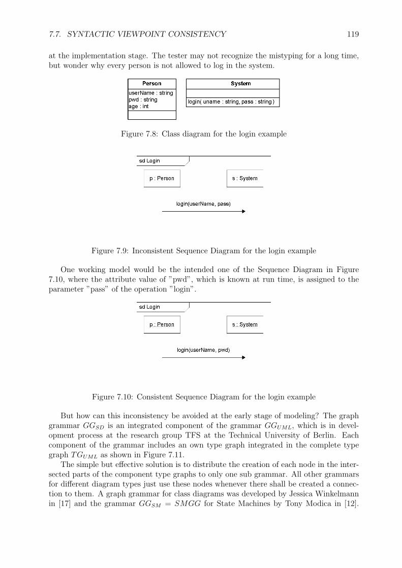
7.7. SYNTACTIC VIEWPOINT CONSISTENCY 119
at the implementation stage. The tester may not recognize the mistyping for a long time,but wonder why every person is not allowed to log in the system.
Figure 7.8: Class diagram for the login example
Figure 7.9: Inconsistent Sequence Diagram for the login example
One working model would be the intended one of the Sequence Diagram in Figure7.10, where the attribute value of ”pwd”, which is known at run time, is assigned to theparameter ”pass” of the operation ”login”.
Figure 7.10: Consistent Sequence Diagram for the login example
But how can this inconsistency be avoided at the early stage of modeling? The graphgrammar GGSD is an integrated component of the grammar GGUML, which is in devel-opment process at the research group TFS at the Technical University of Berlin. Eachcomponent of the grammar includes an own type graph integrated in the complete typegraph TGUML as shown in Figure 7.11.
The simple but effective solution is to distribute the creation of each node in the inter-sected parts of the component type graphs to only one sub grammar. All other grammarsfor different diagram types just use these nodes whenever there shall be created a connec-tion to them. A graph grammar for class diagrams was developed by Jessica Winkelmannin [17] and the grammar GGSM = SMGG for State Machines by Tony Modica in [12].
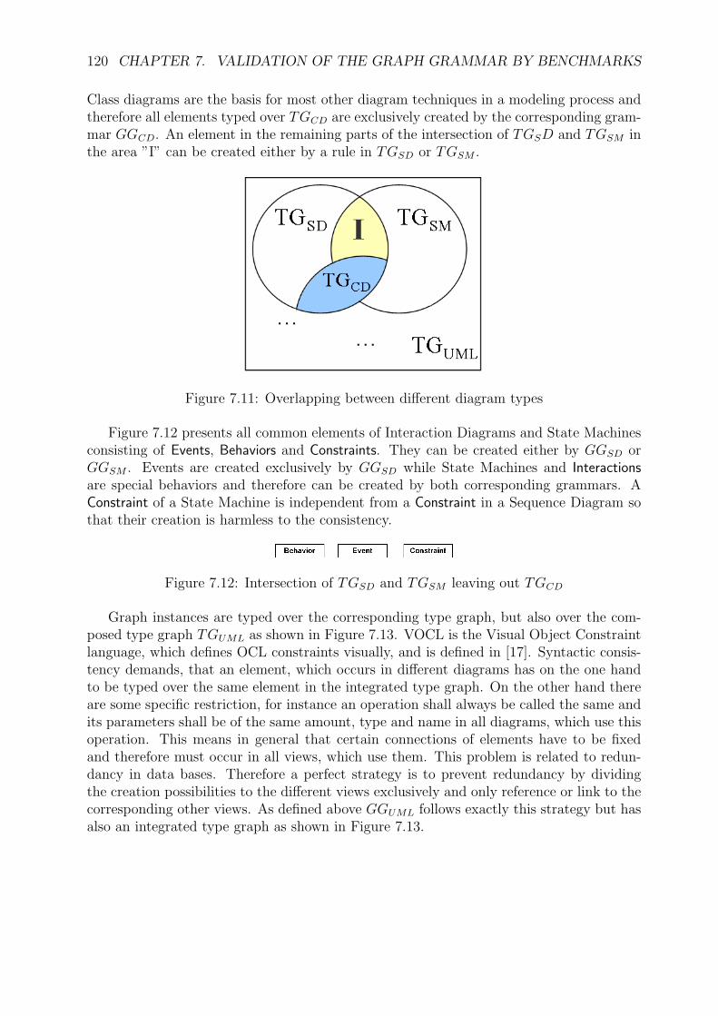
120 CHAPTER 7. VALIDATION OF THE GRAPH GRAMMAR BY BENCHMARKS
Class diagrams are the basis for most other diagram techniques in a modeling process andtherefore all elements typed over TGCD are exclusively created by the corresponding gram-mar GGCD. An element in the remaining parts of the intersection of TGSD and TGSM inthe area ”I” can be created either by a rule in TGSD or TGSM .
Figure 7.11: Overlapping between different diagram types
Figure 7.12 presents all common elements of Interaction Diagrams and State Machinesconsisting of Events, Behaviors and Constraints. They can be created either by GGSD orGGSM . Events are created exclusively by GGSD while State Machines and Interactionsare special behaviors and therefore can be created by both corresponding grammars. AConstraint of a State Machine is independent from a Constraint in a Sequence Diagram sothat their creation is harmless to the consistency.
Figure 7.12: Intersection of TGSD and TGSM leaving out TGCD
Graph instances are typed over the corresponding type graph, but also over the com-posed type graph TGUML as shown in Figure 7.13. VOCL is the Visual Object Constraintlanguage, which defines OCL constraints visually, and is defined in [17]. Syntactic consis-tency demands, that an element, which occurs in different diagrams has on the one handto be typed over the same element in the integrated type graph. On the other hand thereare some specific restriction, for instance an operation shall always be called the same andits parameters shall be of the same amount, type and name in all diagrams, which use thisoperation. This means in general that certain connections of elements have to be fixedand therefore must occur in all views, which use them. This problem is related to redun-dancy in data bases. Therefore a perfect strategy is to prevent redundancy by dividingthe creation possibilities to the different views exclusively and only reference or link to thecorresponding other views. As defined above GGUML follows exactly this strategy but hasalso an integrated type graph as shown in Figure 7.13.

7.7. SYNTACTIC VIEWPOINT CONSISTENCY 121
Figure 7.13: Typing compatibility of different diagrams
With regard to the example the label ”pass” has to be existent already as an attributeof the sending object ”p” or as a known parameter by the enclosing Interaction. As theInteraction does not own a parameter at all and the class of the Lifeline ”p” has no attributecalled ”pass” the rule ”createMessSynch()” on page 66 for creating a synchronous Messageindicated by a filled arrow head could not be applied. The editor would ask the developerto choose the argument by the list of available attributes of ”p” and parameters of theSequence Diagram. Otherwise the developer could cancel the insertion of the Message,insert an attribute ”pass” or rename the existing attribute by a rule of GGCD in the class”Person” and repeat the creation of the Message with ”pass”.
Thus the developer is protected against these simple but heavy to locate failures inthe model. For reasons of efficiency the development process could first use standardeditors and thereafter the diagrams should be recreated automatically or by hand by agraph grammar driven editor. An automatic version corresponds to a parser for the graphlanguage.

122 CHAPTER 7. VALIDATION OF THE GRAPH GRAMMAR BY BENCHMARKS

Chapter 8
Conclusion
Modeling techniques are used to visualize the structure of a system and to specify thebehavior of certain components. Recent years have shown an increase the support ofmodels for the development process by automatic code generation. Currently these modelsonly create a small fraction of the full software system - although in some specializedapplication domains this can be much higher. It remains to be seen in the future as to howmuch of the creation of a system can come directly from the model.
From among the various specification techniques for software systems, UML has provedto be one of the more practicable as it is widely used in industry. Unfortunately, its basis israther modest, since its definition is descriptive. This is particularly apparent with interac-tions, as many constraints are still written in natural language. The graph grammar GGSD
delivers a formal basis for a fraction of UML to gain more more precise analysis possibilitiesand a direct definition for implementation. It strongly corresponds to the abstract syntaxof UML Sequence Diagrams, which model the behavior of a system and especially thecommunication between objects. Aside from State Machines, they are probably the mostfrequently used technique for developers to specify the dynamic behavior. Contrastingly,structural properties are normally modeled by Class Diagrams. The language of sequencediagrams LSD is integrated in the graph language LUML for UML diagrams in general.This chapter summarizes the benefits of the thesis and places it in the context of relatedresearch projects.
Consistency A further aim for researchers of development processes is maintaining con-sistency between the modeled diagrams. Some inconsistencies are recognizable already atearly stages. For instance, syntactic differences between a Class Diagram and a SequenceDiagram can be caused by different names for the same intended element. As an illustra-tion, class ”Person” may be defined in the Class Diagram with an attribute named ”age”.The Sequence Diagram may describe communication between an object ”p” of the class”Person” and an object of the class ”System”. The object ”p” sends a message, which con-tains the attribute ”agge” for a method call. The inconsistency is the mistyped attribute,which does not exist in the Class Diagram. As described in Section 7.7 these errors are notpossible when using the graph grammar GGSD. The basis for this are the dependenciesbetween GGSD and the other grammars for UML diagrams developed in the TFS researchgroup. Section 7.7 describes these dependencies as different viewpoints of the integratedformal language LUML and shows its consistency.
123

124 CHAPTER 8. CONCLUSION
Integrated Graph Grammar Together with other grammars for UML diagrams therewill be a chance to create the integrated graph grammar GGUML, which shall cover most ofthe diagram techniques. Thus, GGSD should be extended by the elements shown in Section6.2. The graph grammar GGSM = SMGG specifying State Machines is in developmentstatus and will be finalized at the end of 2005. VOCL is a visual language representingOCL constraints. Its specification in [17] includes the basic version of Class Diagrams,which is shown in Appendix A. As OCL constraints may define additional restrictionsfor UML models, this language is a suitable supplement for GGUML. Future work on thegraph grammar GGUML will include its application using the related research projects andresults:
Syntax directed Editor Transforming a formal specified model into program code isthe next step for automatic code generation. The first barrier is the creation of a formalmodel by a developer himself. The ”TIGER” project [2] of the TFS research group atthe Technical University of Berlin shall provide a platform to put in the formal definitionof a graph grammar and generate a model-driven editor for the corresponding languagein concrete syntax. This editor allows the developer to use the visual notation, which heis used to. Therefore the designer component allows to define the graph grammar andthe corresponding visual elements. The generator component is then able to produce anEclipse plug-in, which provides a syntax-directed editor.
Figure 8.1: TIGER Project
Figure 8.1 shows the components of TIGER with the import of a formal defined visuallanguage in the red rectangle. It is taken from the proceedings of the 20th IEEE/ACMInternational Conference on Automated Software Engineering (ASE’05). The languagedefinition together with the concrete layout specification of the designer component aretransferred into the generator. At the end a syntax-directed editor is created, which uses theannotated Eclipse technologies shown in the figure. It uses an own file format, containingthe type and start graph. During the editing process the graph transformation tool AGG[15, 11] is used. Apart from the execution of typed attributed graph transformation systemswith node type inheritance it also allows analysis of the transformation system with regardsto termination and conflicts.

125
The TIGER project may abolish the first barrier of a developer to specify a formalmodel. But the second barrier for creating program code out of a formal model is thecreation itself. There are already some approaches for UML diagrams like FUJABA [3],but for many application domains the horizon in this research area is still not reached.
Semantic Consistency The formal specification of UML diagrams is part of the projectIOSIP (Integration of Object-Oriented Software Specification Techniques and their Application-Specific Extension for Industrial Production Systems) aided by the German Research So-ciety (DFG) in the Priority Program Software Specification. A formal semantic is plannedto be applied using Object-Oriented Transformation Systems (OOTS) - defined in [9]. Se-mantic inconsistencies may be detectable by analyzing the semantic models of differentdiagram techniques. Figure 8.2 shows the different views of an integrated model, definedin visual specification techniques. Each viewpoint specification has a corresponding set ofOOTSs, which define their semantics. If no common model exists, the analysis fails andthere is an inconsistency between the views or even a single view has no model.
Specs
OOTS
Figure 8.2: Semantic consistency
Beside the Object-Oriented Transformation Systems in Berlin, there is another ap-proach of a semantics for UML diagrams using transformation systems. The research groupTheoretical Computer Science at the University of Bremen translates UML diagrams inconcrete syntax to graph transformation systems. This process is currently realized by animplemented generator shown in Figure 8.3. These systems can be analyzed and simulated.As an UML diagram may be combined with OCL constraints, to specify more restrictions,these constraints can be checked using the tool ”USE” [14]. A simulation can show, ifthe behavior of the model corresponds to the requirements defined before. This semanticshas been applied to some examples, but as the transformation of a UML diagram to thesemantic transformation system is presently not formally defined.

126 CHAPTER 8. CONCLUSION
Figure 8.3: Semantics via graph transformation
The practically feasible automatic transformation of general specifications in UML tocorresponding implementations may be possible in the future. As described above thereare some approaches including the TIGER project, but the further path may include somestones, which are unknown today. Using a formal basis will certainly reduce this risk.

Part IV
Appendix
127


Appendix A
Graph Grammar for Class Diagrams
The following graph grammar for a simplified version of UML class diagrams was mainlydefined by Jessica Winkelmann in [17]. It is extended in some points and therefore also in-cludes a simple transformation units. Thus the grammar GGCD = (ATGICD, STUCD, SGCD)is a controlled graph grammar. SGCD = {∅}, ATGICD is the type graph in Section A.1and the simple transformation units of STUCD consist mainly of units including just onerule, but in the case of ”InsertGeneralization()” and ”InsertGeneralizationCl()” also show acontrolled structure. Therefore the two rules ”General()” and ”Generalization()” are help-ing rules and do not occur separately in STUCD as encapsulated simple transformationunits.
A.1 Type graph
Class Diagrams model the structure of a system and therefore consist mainly of Classifierstheir Assoziations and their features. The Classifiers may also be linked by Generalizationrelations for specifying the inheritance. Classes are a specialization of Classifiers to definea class of objects at runtime. Features of them are on the one hand Attributes for storinginformation and Operations for executing some behavior or some actions. An Association-Class is a special association including the properties of a Class to provide for instance alsoAttributes. A Class may have roles, which represent some specific properties, which implyspecific behavior of the corresponding objects. Another special Classifier is a Signal, whichmay also have Parameters. The edge ”general” in the type graph allows to define multipleinheritance without cycles with the rules in Section A.2.
129

130 APPENDIX A. GRAPH GRAMMAR FOR CLASS DIAGRAMS
name : stringNamedElement
Generalization
DataType
isActive : boolClass
isRoot : boolisLeaf : boolisAbstract : bool
Classifier
AssociationClass
isNavigable : boolorderingaggregationtargetScope : ScopeKindmultiplicity : Multiplicitychangeability : ChangeableKindvisibility : VisibilityKind
AssociationEnd
Association
ownerScope : ScopeKindvisibility : VisibilityKindmultiplicity : Multiplicitychangeability : ChangeableKindtargetScope : ScopeKindordering : OrderingKindinitialValue : Expression
Attribute
ownerScope : ScopeKindvisibility : VisibilityKindisQuery : boolconcurrancy : ConcurrancyKindisRoot : boolisLeaf : boolisAbstract : boolspecification : string
Operation
kind : PKindEnumParameter
parent
child
feature
feature
type
participant
connectionparameter
general
ConnectableElement
role
TypedElement
Signal
parameter_________order:int
_________order:int
Figure A.1: Type graph of class diagrams
A.2 Rules and Simple Transformation Units
Beside the type graph the controlled graph grammar GGCD contains also the followingsimple transformation units. Most of the following rules represent also simple transfor-mation units, which contain only one rule. Three of them are excepted because they areused to define two more complex simple transformation units. They are: ”General()” and”Generalization()”.
The basic elements of a Class Diagram are DataTypes and Classes, which can be createdby the next two rules.
Figure A.2: Rule InsertDataType()

A.2. RULES AND SIMPLE TRANSFORMATION UNITS 131
Figure A.3: Rule InsertClass()
A feature of a Class may be an Attribute which is also typed, where Classes shall nothave two Attributes with the same name (NAC). Figure A.4 shows the rule for creatingan Attribute.
Figure A.4: Rule InsertClassAttribute()
For executing behavior or actions a Class may also provide Operations, which are createdby the rule ”InsertClassOperation()”.
Figure A.5: Rule InsertClassOperation()
The connection between Classes is specified by Associations, which have special nodes

132 APPENDIX A. GRAPH GRAMMAR FOR CLASS DIAGRAMS
at their ends: AssociationEnds. They are created in Figure A.6 and the condition NACforbids more than one Association with the same names of the created elements.
Figure A.6: Rule InsertAssociation()
A special case of Associations delivers the rule ”InsertAssociationClass()”, which createsan AssociationClass to provide for instance also attributes. As before multiple definedAssociations with the same name connecting the same Classes are not allowed by NAC.
Figure A.7: Rule InsertAssociationClass()
Associations, which connect more than two Classes need the rule ”InsertAssociatio-nEnd()” to define the additional ends, where their names are not allowed to be usedalready for the used Association.

A.2. RULES AND SIMPLE TRANSFORMATION UNITS 133
Figure A.8: Rule InsertAssociationEnd()
The rule in figure A.9 adds a Parameter into an Operation and takes care, that there isnot defined a Parameter for this Operation with the same name.
Figure A.9: Rule InsertOperationParameter()
For multiple generalization relations without cycles the edge ”general” shows the flatgeneralization between all nodes, which are connected via a path of Generalizations. Therule ”General()” calculates this flat relation and is applied after a Generalization was in-serted. The condition PAC ensures, that there is a path between the Classifiers.
PAC1RHSLHS
2 : Classifier
1 : Classifier
General()
: Generalization
child
parent
2 : Classifier
1 : Classifier
2 : Classifier
1 : Classifier
general
PAC2
2 : Classifier
1 : Classifier
: Classifier
general
general
PC= PAC1 xorPAC2
NAC=RHS
Figure A.10: Rule General()
Figure A.11 shows the rule ”InsertGeneralization()” for inserting a generalization be-tween two existing classifiers. The condition NAC1 forbids more than one Generalization

134 APPENDIX A. GRAPH GRAMMAR FOR CLASS DIAGRAMS
between the same Classifiers, NAC2 demands, that the Classifiers are different, and NAC3
ensures, that there is not already a generalization relation in the reverse direction.
Figure A.11: Rule InsertGeneralization()
The following rules are just a simple form of the previous ones, where some attributesof the nodes are predefined.
Figure A.12: Rule InsertDefaultAssociation()

A.2. RULES AND SIMPLE TRANSFORMATION UNITS 135
Figure A.13: Rule InsertDefaultAssociation()
Figure A.14: Rule InsertDefaultAssociationEnd()

136 APPENDIX A. GRAPH GRAMMAR FOR CLASS DIAGRAMS
Figure A.15: Rule InsertDefaultClassifierAttribute()
Figure A.16: Rule InsertDefaultClassifierOperation()
All simple transformation units together for the set STUCD of the controlled graphgrammar GGCD.
Appendix B
Zusammenfassung
Die Benutzung von Modellierungstechniken fr Softwareentwicklungsprozesse bildet die Grund-lage, um Systeme zu entwickeln, welche zum einen in ihrer Gre variabel und zum anderenwhrend der gesamten Laufzeit leicht zu warten sind. Im letzten Jahrzehnt entwickeltesich die Unified Modeling Language UML zur Standardmodellierungssprache in der Infor-matik. Sie bietet verschiedene Diagrammtypen zur Modellierung von Softwaresystemenund ist dabei definiert ber ein integriertes Metamodell.
Diese Diplomarbeit schafft eine formale Basis fr den UML-Diagrammtyp Sequenzdia-gramme, um Konsistenz sicherzustellen, aber auch die Mglichkeit einen syntaxgesteuertenEditor fr diese Diagramme automatisch zu generieren. Dazu werden Sequenzdiagrammemit Hilfe von Graphtransformationen definiert. Eine Graphgrammatik liefert die Regeln,mit denen diese Diagramme erzeugt werden knnen. Dabei wird der kategorielle Ansatzvon DoublePushouts verwendet, fr welchen bereits reichhaltige Analysetechniken vorhan-den sind und in Kombination mit Kontrollstrukturen ermglichen die Regeln komplexeGraphstrukturen zu erzeugen. Hierzu werden gesteuerte Graphgrammatiken definiert undangewendet.
137

138 APPENDIX B. ZUSAMMENFASSUNG
Die selbstandige und eigenhandige Anfertigung dieser Diplomarbeit versichere ich an Eidesstatt.
Berlin, den 28. Oktober 2005
Unterschrift

Bibliography
[1] Donald Bell. UML’s Sequence Diagram. Internet: IBM Rational library, http://www-128.ibm.com/developerworks/rational/library/3101.html, 4(th) August 2005.
[2] M. Beyer and M. Loewe, editors. Generation of Visual Editors as Eclipse PlugIns,2000.
[3] Sven Burmester, Holger Giese, and Wilhelm Schafer. Model-driven architecture forhard real-time systems: From platform independent models to code. In Proc. of theEuropean Conference on Model Driven Architecture - Foundations and Applications(ECMDA-FA’05), Nurnberg, Germany, Lecture Notes in Computer Science (LNCS),pages 1–15. Springer Verlag, November 2005.
[4] Andrea Corradini, Hartmut Ehrig, Reiko Heckel, Michael Lowe, Ugo Montanari, andFrancesca Rossi. Algebraic approaches to graph transformation part I: Basic conceptsand double pushout approach, volume 1: Foundations. Singapore, 1997.
[5] Hartmut Ehrig, Karsten Ehrig, Ulrike Prange, and Gabriele Taentzer. Fundamentalsof Algebraic Graph Transformation. Springer, Berlin, 2005.
[6] Object Managment Group et al. Meta Object Facility (MOF) 2.0 Core Specification,OMG Adopted Specification (ptc/03-10-04). Object Managment Group, October 2003.
[7] Object Managment Group et al. Unified Modeling Language: Superstructure version2.0, Revised Final Adopted Specification (ptc/04-10-02). Object Managment Group,October 2004.
[8] Object Managment Group et al. Unified Modeling Language: Superstructure version2.0, Specification (formal/05-07-04). Object Managment Group, August 2005.
[9] Andreas Kniep. Object-Oriented Transformation Systems. Diploma thesis, TechnicalUniversity of Berlin, Department for Computer Science, 2005.
[10] Sabine Kuske. Transformation Units - A Structuring Principle for Graph Transforma-tion Systems. PhD dissertation, University of Bremen, Department of Mathematicsand Computer Science, 2000.
[11] Boris Melamed. Design and implementation of an attribute manager for conditionaland distributed graph transformation. Diploma thesis, Technical University of Berlin,Department for Computer Science, 1998.
139

140 BIBLIOGRAPHY
[12] Tony Modica. Eine getypte attributierte Graph Grammatik fur syntaxgesteuertesEditieren von UML State Machines. Diploma thesis, Technical University of Berlin,Department for Computer Science.
[13] J. Padberg, H. Ehrig, and L. Ribeiro. Algebraic high-level net transformation systems.Mathematical Structures in Computer Science, 5:217–256, 1995.
[14] Mark Richters. A Precise Approach to Validating UML Models and OCL Constraints.PhD dissertation, University of Bremen, Department of Mathematics and ComputerScience, 2002.
[15] Michael Rudolf. Konzeption und Implementierung eines Interpreters fur attributierteGraphtransformation. Diploma thesis, Technical University of Berlin, Department forComputer Science, 1997.
[16] G. Taentzer. Parallel and Distributed Graph Transformation: Formal Description andApplication to Communication-Based Systems. PhD thesis, TU Berlin, 1996. ShakerVerlag.
[17] Jessica Winkelmann. Spezifikation von Visual OCL: Eine Visualisierung der ObjectConstraint Language. Forschungsberichte der Fakultat IV - Elektrotechnik und Infor-matik 2005/04, Technical University of Berlin, Berlin, February 2005.


![Knowledge Representation and Sense Disambiguation for ... · Interrogatives in Chinese studies are traditionally attributed to the mood category of syntax. Ma [1935] wrote the first](https://static.fdocuments.us/doc/165x107/5f686c7e096ca062682aa8a1/knowledge-representation-and-sense-disambiguation-for-interrogatives-in-chinese.jpg)


