A Tiny Hydraulic Power Supply for an Ankle-Foot Orthosis · A Tiny Hydraulic Power Supply for an...
92
A Tiny Hydraulic Power Supply for an Ankle-Foot Orthosis Volume II Team Members: Luis Caceres Chad Feeny Nick Giannetti, Stephanie Haugen Karl Hegna Dmitrii Pokhil Advisor: William Durfee Advisor Assistants: Jicheng Xia Brett Neubauer Sponsor: Center for Compact and Efficient Fluid Power
Transcript of A Tiny Hydraulic Power Supply for an Ankle-Foot Orthosis · A Tiny Hydraulic Power Supply for an...

A Tiny Hydraulic Power Supply for an
Ankle-Foot Orthosis
Volume II
Team Members:
Luis Caceres
Chad Feeny
Nick Giannetti,
Stephanie Haugen
Karl Hegna
Dmitrii Pokhil
Advisor:
William Durfee
Advisor Assistants:
Jicheng Xia
Brett Neubauer
Sponsor:
Center for Compact and Efficient Fluid
Power

Contents 1 Problem Definition Supporting Documents ......................................................................................................... 1
1.1 Annotated Bibliography ................................................................................................................ 1
Summary ....................................................................................................................................... 1
References ..................................................................................................................................... 1
1.2 Patent Search ................................................................................................................................. 5
Objective ....................................................................................................................................... 5
Search Criteria ............................................................................................................................... 5
Findings ......................................................................................................................................... 5
1.3 User Need Research ...................................................................................................................... 6
1.4 Concept Alternatives ..................................................................................................................... 7
Axial Piston Pump Parameters ...................................................................................................... 7
Integration Concepts ...................................................................................................................... 7
Solenoid Valves ........................................................................................................................... 10
1.5 Concept Selection ........................................................................................................................ 10
Axial Piston Pump Parameters .................................................................................................... 10
Integration Concepts .................................................................................................................... 21
Solenoid Valves ........................................................................................................................... 26
2 Design Description Supporting Documents ....................................................................................................... 27
2.1 Manufacturing Plan ..................................................................................................................... 27
2.1.1 Manufacturing Overview ............................................................................................................. 27
2.1.2 Part Drawings .............................................................................................................................. 27
2.1.3 Bill of Materials ........................................................................................................................... 28
2.1.4 Manufacturing Procedure ............................................................................................................ 28
3 Evaluation Supporting Documents Table of Contents ....................................................................................... 30
3.1 Evaluation Reports ...................................................................................................................... 30
Structural Integrity – Manifold .................................................................................................... 30
Structural Integrity - Pump .......................................................................................................... 35
Pump Performance (Efficiency) and Max Flow Rate .................................................................. 43
Total Weight ................................................................................................................................ 46
Total Size/Comfort ...................................................................................................................... 48
3.2 Cost Analysis ............................................................................................................................... 50
3.3 Environmental Impact Statement ................................................................................................ 50
3.4 Regulatory and Safety Considerations......................................................................................... 51
Appendix A ................................................................................................................................................................. 53
Appendix B .................................................................................................................................................................. 56
Appendix C .................................................................................................................................................................. 59

1
1 Problem Definition Supporting Documents
1.1 Annotated Bibliography
Summary
Many topics needed to be researched to gain an understanding of every component in the HPS.
Background information relating to ankle functionality and ankle impairments was needed to
understand the use of AFOs. AFOs were researched to understand what the HPS would be
powering. Research was done on axial piston pumps, their functionality, characteristics and
optimization. DC motors, valves, reservoirs, hydraulic circuits, and additive manufacturing were
also researched. For valves, check valves and pilot-operated check valves were focused on.
Research was also done on solenoid valves. For batteries, a focus was placed on the lithium-ion
variety.
Research on axial piston pumps was extremely important, as designing the pump was one of the
main challenges of the design. Important topics involved learning how each pump component
can be optimally designed for efficient performance. Examples included deciding how many
pistons and what swash plate angle should be used. An understanding of DC motors and batteries
was important to know what the current technology is capable of, and what options were
available. This allowed for them to be chosen together to match the requirements for the pump.
A properly designed reservoir required research to maximize cooling and reduction of sloshing.
Research needed to be done to decide if there were check valves that could fit the HPS
application or if custom ones were necessary. Additive manufacturing was researched to
discover the current technology that exists in 3D printing. Seeing the design realized would
greatly benefit from the use of additive manufacturing.
References
[1] Hsiao-Wecksler, E., 2013, “Human Assist Devices - Fluid Powered Ankle-Foot Orthosis
(Test Bed 6).”
This page discusses research towards a testbed for a fluid powered AFO. It has succinct
descriptions of the challenges and technology of AFOs. It is not a useful page for designing the
HPS.
[2] Shorter, K., Xia J., Hsiao-Wecksler, E., Durfee, W., and Kogler, G., 2011, “Technologies for
Powered Ankle-Foot Orthotic Systems: Possibilities and Challenges.”
This paper discusses the current technologies that exist for AFOs. There is useful background
information on both AFOs and the medical information behind ankle functionality and ankle
impairments.
[3] Manring, N. D. and Damtew, F. A., 2001, “The Control Torque on the Swash Plate of an
Axial Piston Pump Utilizing Piston-Bore Springs.”

2
This research begins by presenting a non-traditional pump design which utilizes a piston bore
spring. The piston-bore springs hold the cylinder block against the valve plate and force the
pistons in the opposite direction. By forcing the pistons in this direction, the piston-bore spring
also assists in holding the slippers against the swash plate during the normal operation of the
pump. Though these advantages of the design may be readily seen by inspection, it is not
obvious how the control torque on the swash plate is affected by the piston-bore spring nor is it
obvious how one would go about designing the spring to produce a favorable result. To clarify
the benefit of this design, a mechanical analysis is conducted to describe the effect of the spring
on the control torque itself.
[4] Manring, N., 2000, "The Discharge Flow Ripple of an Axial Piston Swash-Plate Type
Hydrostatic Pump," Journal of Dynamic Systems, Measurement, and Control, 122, pp. 263-268.
This research examines the idealized and actual flow-ripple of an axial piston swash plate type
hydrostatic pump. For the idealized case, a ‘‘perfect’’ pump is examined in which the leakage is
considered to be zero and the fluid is considered to be incompressible. Based upon these
assumptions, closed-form expressions which describe the characteristics of the idealized flow-
ripple are derived. Next, the actual flow-ripple of the pump is examined by considering the pump
leakage and the fluid compressibility and for computing these results a numerical program is
used. For both the idealized case and the actual case a comparison is made between a nine-
piston, an eight-piston, and a seven-piston pump.
[5] Buchmann, I., “Types of Lithium-Ion Batteries,” from
http://batteryuniversity.com/learn/article/types_of_lithium_ion
This page offers detailed comparisons of a few of the most popular types of lithium-ion batteries.
It has a few very useful graphics detailing their characteristics and their differences. This can be
used to help choose which lithium-ion battery should be used for the HPS.
[6] Vorkeotter, S., 2002, "How Electric Motors Work," from
http://www.stefanv.com/rcstuff/qf200212.html
The author runs an aviation information website and included this article for people looking at
electric motors for RC airplane usage. The purpose of the article is to give an overview of the
function of an electric motor and the physics behind their operation. This web page is a general
overview of electric motors, beginning with a discussion of magnets and how they are used to
create electric motors. This article is a broad overview and contains little specific information.
[7] Kafader, U., 2009, "Selecting DC Brush and Brushless Motors," 2009, from
http://machinedesign.com/article/selecting-dc-brush-and-brushless-motors-0217
This article is published by a site that offers a wide range of engineering-specific information.
This information is not as much about how a DC brushless motor works, but more about the
factors that determine their use and operation. The article assumes the reader has a basic
understanding of a DC motor and immediately begins explanation of the pertinent design
considerations that must be made while choosing a motor to use for a given application.
3
[8] “Direct Metal Laser Sintering (DMLS),” n.d., from
http://www.gpiprototype.com/services/dmls-direct-metal-laser-sintering.html
GPI prototype is a company that provides DMLS services. This website includes data sheets on
the materials as well as examples of products which they have printed.
[9] “DMLS, Additive Metal Manufacturing,” n.d., from
http://www.morristech.com/Technologies/?cat=DMLS
Morris Technologies provides DMLS, Electron Beam Melting, and other rapid prototyping
services. The page includes information about the capabilities of their services.
[10] “Materials and Material Management,” n.d., from
http://www.eos.info/a4a6c5227249b83d/materials-and-material-management
EOS build DMLS machines which have become the industry standard of DMLS printing. Their
website includes systems and solutions as well as information regarding the capabilities of their
machines.
[11] “Lee Cheks,” 2013, from
http://www.theleeco.com/VALVWEB2.NSF/Chek Products!OpenView
This is the official Lee Company website. They are a leading supplier in precision fluid control
products, specifically on the miniature side. This page in particular has specifications and data
sheets for their various check valves. This will be useful if their products are used.
[12] "2-Way High Flow Piloting Solenoid Valve." n.d., from
http://www.theleeco.com/PLUGWEB2.NSF/51afc74e7f2112c9852563a9005db170/e71e9bb8dd
7e65f285257427006474fc!OpenDocument
This is the official Lee Company website. Specifically, this is the webpage that contains
information on their 2-way high flow piloting solenoid valve.
[13] Xia, J., 2013, Ph. D. Student, Center for Compact and Efficient Fluid Power, personal
communication.
Jicheng Xia was the Ph. D. student working on modeling and defining the HAFO system. Many
e-mails and conversations were exchanged to provide the group with the information needed to
design the HPS.
[14] Xia, J., 2013, "Modeling and Design of Small-Scale Hydraulic Power Supply", Center for
Compact and Efficient Fluid Power, Power Point.
Jicheng Xia created a power point regarding the HPS, which provided figures and information
used in the report.

4
[15] Eaton, 2010, Eaton Fluid Power Training Industrial Hydraulics Manual, Eaton
Corporation, Maumee, OH, Chap. 12.
This textbook provides a general overview of everything and anything regarding hydraulic power
systems and components. This source was used to demonstrate how a manifold block system
worked to incorporate multiple valves in one piece. In addition, it describes the basics of
reservoirs and common reservoir designs.
[16] Mehta, V., 2006, “TORQUE RIPPLE ATTENUATION FOR AN AXIAL PISTON SWASH
PLATE TYPE HYDROSTATIC PUMP: NOISE CONSIDERATIONS,” Ph.D. dissertation,
Department of Mechanical Engineering, University of Missouri.
This research analyzes the critical challenge in fluid power industry of excessive noise
generation by axial piston pumps. Thorough background information is given detailing the
understanding of this problem and mechanisms involved with it. Some of the standard and in-test
methods to alleviate the problem and work in progress by different research groups are presented
subsequently. A theory highlighting a different origin of the problem is proposed that challenges
the generally accepted view about the noise problem in axial piston pumps and further sets
foundation for analysis.
[17] Bowerman, T., 2013, Sales Engineer, The Lee Company, private communication.
E-mails were exchanged with Tom Bowerman to get product drawings and prices for The Lee
Company’s pilot operated check valves, solenoid valves, and plugs.
[18] Lyons , J. L. and Askland Jr., C. L., 1975, Lyons’ Encyclopedia of Valves, Van Nostrand
Reinhold Company, New York, NY.
This book covers the basic definitions for a variety of valve types. It outlines equations for
designing valves to meet specified requirements, provides detailed drawings of various valves
and advises which valve to use for particular applications.
[19] Pelosi, M., 2012, “An Investigation on the Fluid Structure Interaction of Piston/Cylinder
Interface,” Ph. D. dissertation, Purdue University
The aim of this research was to deepen the understanding of the main physical phenomenon
defining the piston/cylinder fluid film and to discover the impact of surface elastic deformations
and heat transfer on the interface behavior. For this purpose, the author developed a unique fully
coupled multi-body dynamics model to capture the complex fluid-structure interaction
phenomena affecting the non-isothermal fluid film conditions.
[20] Li, Z., 2005, “Condition Monitoring of Axial Piston Pump,” M.S. thesis, Department of
Mechanical Engineering, University of Saskatchewan.

5
In this study, wear (and hence leakage) between the pistons and cylinder bores in the barrel was
of interest for an axial piston pump. In an axial piston pump, wear between the various faces of
components can occur in many parts of the unit. As a consequence, leakage can occur in
locations such as between the valve plate and barrel, the drive shaft and oil wiper, the control
piston and piston guide, and the swash plate and slippers.
[21] Kosodo, H., 2012, "Development of Micro Pump and Micro-HST for Hydraulics," JFPS
International Journal of Fluid Power System, 5-1.
This paper briefly explains the basic technology of micro axial piston pumps, realizing the recent
developments. It also gives examples of the essential parts and applications. The authors want to
make the best use of their original design and precision process capability for the further
development of micro axial piston pumps, motors and HST to meet the demand from society and
industry.
[22] Kim, J.; Kim, H.; Lee, Y.; Jung, J. and Oh, S., 2005, "Measurment of Fluid Film Thickness
on The Valve Plate in Oil Hydraulic Axial Piston Pumps (Part II: Spherical Design Effects)."
Journal of Mechanical Science and Technology, 19.2, pp. 655-663.
In this study, the fluid film between the valve plate and the cylinder block was measured by
using a gap sensor and the mercury-cell slip ring unit under real working conditions. To
investigate the effect of the valve shape, the authors designed three valve plates each having a
different shape. One of the valve plates had a flat surface, another valve plate had a bearing pad
and the last valve plate had spherical valve geometry. It was noted that these three valve plates
observed different aspects of fluid film characteristics between the cylinder block and the valve
plate. The leakage flow rates and the shaft torque were also investigated in order to clarify the
performance difference between the three types of valve plates.
1.2 Patent Search
Objective
The tiny HPS consists of many components including a battery, electric motor, bidirectional
axial piston pump, tank, solenoid valves, and a pilot operated check valve. From these
components, the bidirectional axial piston pump and the valves could be custom designed. For
this reason, it was important to be aware of patents that could be similar to the designs. In
addition to designing new components, the integration among them was fundamental for this
project. In consequence, patents that could relate to the future arrangement were searched.
Search Criteria
The patents search was done using the Google database. The keywords used to find patents
related to the HPS were: hydraulic power supply, bidirectional axial piston pump, check valve,
pilot operated check valve.
Findings
Patent: Hydraulic device

6
Number: US20050175467
US Classification: 417/217
International Classification: F04B049/00
Description: This invention is a fluid pressure apparatus. Similar to the HPS, it consists of an
electric motor coupled to a bidirectional axial piston pump, one check valve, and a pilot operated
check valve. Something important to note is the similarity between the proposed hydraulic circuit
for the HPS, and the hydraulic circuit for this power supply, especially the configuration of the
check valves. However, this patent presents a low level of threat to the patentability of the tiny
HPS. The main aspect to note is that the function of the device from the patent, and the HPS is
not the same. In addition, even though both designs share similar components, the configuration
of them is not exactly the same.
Patent: Axial piston machine constructed in a removable cartridge form to facilitate assembly
and disassembly
Number: US4611529
US Classification: 91/499; 92/128; 417/269; 417/271; 417/360
International classification: F01B 1304
Description: This invention is an axial piston pump. The design of this device is almost identical
to the proposed design for the HPS pump. Some of the components that the designs have in
common are: the swash plate, cylinder barrel, valve plate, piston shoes, pistons, and centralized
shaft. This patent poses a high level of threat to the pump patentability, since their operation
principles and components are similar. However, something to note is that the axial piston pump
from the patent is not bidirectional.
Patent: Check valve
Number: US2005/0115616
US Classification: 137/540
International classification: F16K015/02
Description: This invention is a check valve. It consists of a poppet, a spring, and an adjustable
plate that reduces or increases the length of the spring in order to vary the cracking pressure of
the valve. The proposed design for the HPS check valve is very similar to this one; it would also
consist of a poppet and a spring. However, unlike the patent, the custom check valve would not
have an adjustable plate, since the cracking pressure will be fixed. In spite of this, this patent
presents high threats to the check valve patentability.
1.3 User Need Research
The user needs were determined through an interview with Jicheng Xia [13]. The CCEFP is the
main user that the design needed to satisfy. The transcribed questions and responses are given in
Appendix B.
1. HPS produces enough power

7
Power requirements took the highest priority. This is because without enough
power the AFO cannot sufficiently replicate the power of a human ankle.
2. HPS is light, compact and comfortable to wear
The HPS needs to meet all of these criteria so it can be worn daily comfortably. If
the supply is not feasible to wear, the design is not sufficient.
3. HPS is safe
Safety was ranked next because it takes into account the structural integrity of the
HPS and the requirement that it not fail. A failure in a high pressure hydraulic
system that is worn on the body can result in serious injury.
4. Sufficient operation time
Ideal values of an hour and 10,000 steps would allow users to make moderate
distance trips on one charge. This is important, but could easily be adjusted by
varying the battery size.
5. HPS has high efficiency
This was ranked last because it was not a main concern for the HPS. It is still
important to strive for high efficiency to minimize losses and create a quality
product.
1.4 Concept Alternatives
The components needed to create the hydraulic power supply circuit were given: axial piston
pump, valves, reservoir, motor, and battery. How these components could be optimized, how
they would be integrated and where each attaches to the human body was the design task. The
solenoid valves could have been purchased or custom designed. In addition, it was necessary to
design a custom axial piston pump to meet the output and weight requirements.
Axial Piston Pump Parameters
For the design of the axial piston pump, the parameters of every component needed to be
considered. This resulted in complex design choices regarding the valve plate, cylinder barrel,
pistons, slippers and swash plate.
Integration Concepts
The integration concepts can be categorized into two parts, body placement and component
configuration. The power supply could be attached to the body in the three following ways:

8
Figure 1. Backpack style Figure 2. Waist style
Figure 3. Crossbody style
Within the power supply, the components could be arranged in various configurations. Figure 4
outlines the initial power supply circuit diagram that was given.

9
Figure 4. Initial hydraulic circuit diagram [13]
The “Power Package” portion of Figure 4 is the components and fluid lines that were focused on.
A few possible configurations of motor, pump, check valve, pilot operated check valve and
reservoir are outlined in Figures 5 through 7.
Figure 5. Concept 1 Figure 6. Concept 2
Figure 7. Concept 3
These models were meant to provide a high level visualization of where each piece could be
positioned within the whole. The dimensions of each piece were arbitrary at this concept stage.
The red part represents the pilot operated check valve, orange the check valve, blue the pump,

10
purple the reservoir and green the motor. The battery was not included in the configuration
concepts because it is intended to be detachable, therefore allowing a multitude of placements.
Solenoid Valves
Two options were explored when deciding which solenoid valve to incorporate into the HPS:
custom designing the valve or purchasing the valve from The Lee Company, who manufacturer
the smallest valves on the market.
1.5 Concept Selection
This section validates the concept selections based on a logical and supported decision making
process.
Axial Piston Pump Parameters
Valve Plate
Relief Grooves
In order to reduce the noise of the pump and make the output flow more even, there are specially
designed relief grooves on valve plates, as shown in Figure 8. The two relief grooves have a “V”
shape, which starts at zero depth near TDC or BDC and then reaches a maximum depth at the
beginning of the outlet ports. The relief grooves expose the piston cylinder to the outlet or inlet
ports in the valve plate in a more gradual manner, which helps to facilitate a slower pressure
gradient in the piston cylinder. From a noise point of view, a very sharp pressure gradient can
translate into a loud knocking sound in the pump and should be avoided. Figure 9 shows a
comparison of the transient pressure between a valve plate with relief notches and one without
relief notches. From both of the figures, it is apparent that the relief notches force the transient
pressure gradient to be more gradual than when there are no notches. In reality, the pressure
overshoot for some situations involving a valve plate without the relief grooves can actually be
quite severe. Figure 10 provides the nomenclature for Figures 8 and 9 [20].
Figure 8: Relief Grooves for Uni-directional Pump [20]

11
Figure 9: Relief Grooves for Uni-directional Pump [20]
ϕ: cylinder angle on valve plate
Figure 10: Geometry Nomenclature [20]
Port Openings (Kidney Ports)
The distance from the inner radius of the port opening, to the outer radius was proportionally
based off of an industry axial piston pump design by Takako. The radii match the port openings
of the cylinder barrel. The swept angle of curvature of the port openings was also based off of
the Takako design.
Spherical Surface
The utilization of a spherical valve plate offers the following benefits:
Stable performance, even at high-speed and high-pressure
Tolerant of high inlet vacuum
More tolerant of system contamination
Torque efficiency is high, thus reduce the energy loss

12
The increase in temperature is less and degradation of fluid oil is less.
High efficiency can be maintained in a wide range of rotation speed [21]
Additionally, a spherical valve plate encourages better fluid film patterns and performance
compared to that of a flat valve plate geometry. Below in Figures 11 through 15, VP1 is a flat
valve plate geometry and VP3 is a spherical valve plate geometry. Looking at Fig. 11, a spherical
valve plate has less variation in fluid film thickness compared to a flat valve plate geometry
across a rotational speed range that includes the tiny HPS system. As well, in Fig. 12 it can be
observed that there is little fluctuation in the fluid film thickness for a spherical valve plate
between the discharge and suction region across the range of pressures, again including the HPS
system. Comparing the flat and spherical valve plate geometries in Fig. 13, across the pressure
range of 5-30 MPa, the spherical valve plate has the least variation in fluid film thickness. In Fig.
14, comparing the leakage flow rates between the flat and spherical valve plate geometries, again
it is seen that the spherical valve plate geometry is the most effective and results in the least
leakage flow rate.
Figure 11: Minimum fluid film variations with
rotational speed at 20 MPa [22]
Figure 12: Fluid film variations on the spherical
valve plate (VP3) [22]
Figure 13: Difference between maximum and
minimum fluid film [22]
Figure 14: Comparison of the leakage flow
rates [22]

13
Finally, it is seen in Fig. 15 that a spherical valve plate has the highest efficiency at the higher
discharge pressure range.
Other benefits of a spherical valve plate geometry include that it could remarkably reduce both
the shaking and the tilting of the cylinder block over all driving conditions, as can be observed
by the fluid film thickness comparisons in Figures 11 through 13 [22].
Circumferential Flat Surface
Since the axial piston pump design in the HPS does not have its own shaft running through the
whole pump, a circumferential flat surface would be beneficial in assisting alignment of the
cylinder barrel on the valve plate and reducing eccentricity of the cylinder barrel from the axis of
rotation. Additionally, the ring resulting from the valve plate surface geometry changing from
flat to spherical may enhance the seal on the spherical surface.
Center Hole
A hole in the center of the valve plate was designed as a location for excessive oil resulting from
leakage to be able to collect resulting in a reduction of oil build-up in other undesirable locations.
Also, this hole is concentric with the cylinder barrel shaft hole, which will further allow for oil to
be conveniently collected and enable even lubrication along mating surfaces if lacking.
Grooves on Bottom
Grooves were designed on the bottom of the valve plate. This allows fluid resulting from leakage
to flow through the groove passages into the center of the valve plate or to the outside, rather
than creating an undesirable excessive fluid film build-up beneath the valve plate.
Mounting Style
The design includes notches that are cut on either side of the circumference on the underside, not
exposed to the upper surface. They were located at the bottom and top dead center locations as
this is where the lowest and highest pressures occur, respectively. Thus, having mounts for
security at these locations was favorable to reduce valve plate eccentricities. Additionally, the
notches are exposed to the outside circumference of the valve plate to minimize undesired fluid
buildup at the mounts as well as to allow fluid resulting from leakage collected beneath the valve
Figure 15: Comparison of the total efficiency [22]

14
plate to travel to the outside of the plate through grooves connecting the notches. The positioning
of the notches, from an engineering perspective, allows the simplest method of positioning it
within the manifold when assembling the power supply.
Plate Thickness
Plate thickness was determined proportionally between the Parker Hannifin Oildyne and Takako
valve plate designs. It was then verified to be structurally sound using the finite-element analysis
software, ANSYS.
Cylinder Barrel
Overall Length
The overall length was designed proportionally based on the Parker Hannifin Oildyne pump,
which is of similar cylinder barrel radius.
Outer Barrel Radius, Piston Cylinder Radius, Piston Cylinder Pitch Radius
These dimensions were optimized using a MATLAB program that took criteria into account such
as minimum flow rate, minimum shaft diameter, minimum piston wall thickness, and number of
pistons while maximizing theoretical efficiency and minimizing overall outer radius.
Piston Cylinder Depth
The depth of the cylinders was equivalently based off of the Parker Hannifin Oildyne design
Cylinder Wall Thickness
The minimum cylinder wall thickness was proportionally based off of the Parker Hannifin
Oildyne design, taking into account a lower maximum operating pressure and smaller piston
cylinder diameter. This was then verified to have deformation within an allowable range using
finite-element software, ANSYS.
Piston/Cylinder Gap Thickness
Figure 16 shows an exaggerated visualization of the fluid film thickness encompassing the piston
within the cylinder.
Figure 16: Piston/cylinder unwrapped fluid film thickness [19]

15
For micro-pumps, the fluid film thickness could vary anywhere between 7-19 microns. For the
HPS design, a gap thickness was taken from the 0.4cc Takako pump.
Shaft Radius
The minimum shaft radius was determined through basic reversible maximum shear stress
calculations assuming common structural steel as the material of the shaft.
Shaft Lock
The shaft locking mechanism design was based off of commonly used designs for preventing
shaft rotation within an object. The flat surface’s normal radial distance to the center of the shaft
was proportionally designed off of other shafts with similar radii.
Outer Edge Chamfers
The edges have a slight chamfer to encourage hydraulic fluid to readily flow between the outer
housing and cylinder barrel surface. This is to improve the lubrication and reduce friction
between the two surfaces, as well as reducing heat buildup. This in turn increases rotational
efficiency.
Spring Seat
The choice of designing a spring seat at the bottom of the piston cylinder was encouraged by the
Parker Hannifin design which also included spring seats. The spring seat prevents any lateral
movement (movement perpendicular to that of the motion of the piston) of the spring, thus
retaining the spring in a vertical position at all times in-line with the motion of the spring. This is
necessary, as any undesirable friction and energy loss is reduced due to the piston not having to
center the spring during its motion if the spring is allowed to move laterally. Additionally, the
spring seat is roughly two-thirds of a complete circle allowing fluid to flow out and not become
trapped in the seat, resulting in loss of piston stroke efficiency. To further aid efficient fluid flow
out of the piston seat, the ends of the two-thirds enclosed circle are chamfered to allow smoother
fluid discharge through the seat. The depth of the spring seat is such to allow the lowest spring
rung to be completely restrained from lateral movement.
Overall Outlet Thickness
The overall outlet thickness is proportionally based off of the Parker Hannifin and Takako
designs taking into account maximum operating pressure and piston end surface area.
Dimensions were confirmed to have an allowable stress and deformations within an adequate
range at the maximum operating pressure.
Port Opening Shape
The port openings on the cylinder barrel were designed similar to that of the Takako pump. They
were made to match the port openings on the valve plate. A kidney like shape is recessed into the
port opening at a depth proportional to that of the Takako pump, taking into account the radius of

16
the pistons and overall radius of the cylinder barrel. This was done to encourage a smoother
transition from the two port openings in the valve plate, minimizing flow ripple as described
previously.
Cylinder Barrel and Housing Gap
The cylinder barrel and housing gap was based off of the measured gap on the Parker Hannifin
design. It is the minimal gap necessary for the cylinder barrel to float freely within the housing,
minimizing viscous shear while still being lubricated properly.
Piston
Piston-Bore Springs
The piston-bore spring is included in this design for the purpose of holding the cylinder block
against the valve plate, and for forcing the pistons in the opposite direction. By forcing the
pistons in this direction, the piston-bore springs also assist in holding the slippers against the
swash plate during the normal operation of the pump. The piston-bore springs have been
observed to be capable of eliminating the crossover from a stroke. This increases the swash-plate
torque to a stroke decreasing swash-plate torque. By eliminating this cross over, the backlash in
the pump control (which has been commonly observed in practice) can be prevented. The kinetic
energy stored in the piston-bore springs provides a restoring force on the swash plate which
always tries to drive the swash plate to a minimum position. This is specifically the stabilizing
influence. If all of the natural forces acting on the swash plate tend to drive the swash-plate angle
to a minimum value, it has been shown that the control torque will only be required to drive the
pump into stroke. This singular direction of effort will prevent backlash within the pump control.
This is a significant contribution to the design since control backlash causes adverse wear within
the pump and may also create an undesirable output from the pump during the backlash
condition [3].
Spring Stiffness
( ) (1)
Mp = Mass of Piston
Ms = Mass of Spring
Equation 1 is based off of spring natural frequency, and was used as a guideline for designing the
spring rate of the piston-bore spring for guaranteed stability of the swash plate. A properly
designed spring rate is used to absorb the kinetic energy associated with the reciprocating inertia
of the piston-slipper assemblies within the pump [3]
Spring Length
For the springs and pump to operate efficiently and effectively, they must always be in
compression. Thus, the springs were designed so they are relatively 1.25 times the length of the
inner portion of the piston.
Length

17
The length of the pistons was equivalently designed based off of the Parker Hannifin Oildyne
design.
Wall Thickness
The wall thickness was designed proportionally to that of the Parker Hannifin design, taking into
account a smaller piston cylinder diameter and the manufacturability of the piston-bore springs.
Additionally, the pistons were analyzed with finite element software, ANSYS, to verify that
deformation beyond an allowable range did not occur at the maximum operating pressure.
End Ring
A ring was cut into the end of the piston proportional to that of the Parker Hannifin design,
taking into account the piston radius. This ring is there such to encourage a build-up of fluid film
around the piston for lubrication, as well as to create a fluid seal around the piston. The cut is
made at 90 degrees to not over encourage fluid flow past the piston, but rather to maintain a
relatively proper pumping surface.
Piston Bore Depth
The bore depth was made proportionally similar to the Parker Hannifin design, taking into
account piston radius. The piston is not completely hollowed so it will still maintain some mass
necessary for more even harmonic motion when fluidic resistance is introduced.
Chamfer at Piston Head Base
A chamfer was added at the base of the piston head to allow a less resistant motion if excessive
fluid due to leakage occurs behind the piston.
Piston Head
The head of the piston is designed similarly to that of the Parker Hannifin design, such that the
radius is the same as the outer radius of the piston.
Piston Head Neck
The radius is designed such that it is structurally capable of resisting lateral forces imposed by
the slipper and piston during the pump process. Also, the radius is small enough as to not
interfere with the movement of the slipper at various angles during movement around the swash
plate.
Through Hole
A small pin hole was designed through the whole piston similarly to the Takako design such that
there is always some minimal fluid leakage to the piston head to provide proper lubrication
between the piston head surface and inner slipper surface.
Number of Pistons

18
The process of choosing the number of pistons was heavily based on a phenomenon called flow
ripple that occurs during pumping in an axial piston pump. Positive displacement piston pumps
generate a flow ripple that is created by the pumping action of the pistons and the valve in the
pump. The total flow is composed of the summation of flows from individual pistons and is a
periodic function of time with a fundamental frequency that corresponds to the piston pass
frequency. Further, it is known that flow variation during pumping is caused by periodic
variation in geometric displacement and oil compression and expansion processes at transitions
between high and low pressure. As mentioned previously, the reason for geometric displacement
variation is that the total flow is a summation of the flows from individual pistons. This flow
variation is known as flow ripple which is categorized as a kinematic flow ripple and a dynamic
flow ripple. The dynamic component is much worse, both in amplitude and frequency than the
kinematic flow component, since the contribution of dynamic flow ripple is significantly higher
towards the total flow ripple. It is very intuitive to suggest that the smoother the flow, the lower
the noise [16].
It is observed that choosing an odd number of pistons is the first step to minimize flow ripple.
Further, it is seen that with greater number of pistons, flow ripple is further minimized.
Using the MATLAB optimization program that was developed, it was discovered that a design
that was capable of being manufactured with the highest efficiency was a 7 piston design.
However, due to constraints of machinability and lack of availability of such small piston-bore
springs, the next design choice was 5 pistons.
To firmly assure that the efficiency of a 5 piston design outweighed the simplicity of
manufacturing a 3 pistons design, the following criteria were used.
Looking at Figures 17 and 18, it can be observed that with 5 pistons, a greater overlap of flow
during discharge/intake occurs, resulting in a more even flow output.
Idealized Flow Ripple Differences
• Irregularity of the kinematical pulsations can be expressed with
–
(2)
• Pulsation factor (%) for an odd number of pistons
– (
) (3)
• Comparing pulsation z = 3 pistons vs z = 5 pistons
– ( )
Figure 17. Flow Ripple 3-Piston Pump [4] Figure 18. Flow Ripple 5-Piston Pump [4]

19
– ( )
• The use of 3 pistons results in an 8.5% increase of kinematic pulsation factor compared to
the use of 5 pistons
Idealized Flow Ripple
• Normalized height of the flow pulse for a pump with an odd number of pistons
– ̂
(
) (4)
• Comparing normalized flow pulse height for 3 pistons vs 5 pistons
– ̂( )
– ̂( ) • With 3 pistons there is a 40% increase in normalized flow pulse height compared to that
of 5 pistons
3 Pistons vs 5 Pistons
• There is a significant difference between 3 and 5 piston flow ripples
• The use of 3 pistons results in an 8.5% increase of kinematic pulsation factor over the use
of 5 pistons
• With 3 pistons, there is a 40% increase in normalized flow pulse height compared to that
of 5 pistons
Five pistons is a better choice when observing flow ripple, as that is something that should be
minimized. Also, the complexity of making a 5 piston design is not significantly more difficult
than a 3 piston design [4].
Top Dead Center Gap
The top dead center gap between the top of the piston and the bottom of the piston cylinder face
was proportionally based off of the distance in the Parker Hannifin design. A gap is designed
into the pump as a safety precaution to prevent the piston from knocking against the cylinder
barrel face in the event of irregular piston reciprocation that the spring is unable to prevent.
Slipper
Length
The length was made proportional to that of the Parker Hannifin design, taking into account the
smaller piston radius. Additionally, it was made so that it would not collide with the piston head
neck during the various angles of eccentricity it undergoes during movement around the swash
plate.
Wall Thickness
The wall thickness was based off of the Parker Hannifin design, such that the walls could
structurally withstand the force of the piston head during pumping.
Top Thickness

20
The top thickness was based off of the Parker Hannifin design such that it does not deform from
the force of the piston head during pumping. It was also made thick enough to allow space for
relief grooves to be cut on top of it.
Inner Spherical Bore
A spherical bore is commonly used among slipper designs. In comparison to a simple cylindrical
bore, a spherical bore allows for a more evenly distributed force along the piston head, thus
resulting in a more even transfer of forces through the piston. The desired oil leakage through the
pin hole of the piston will result in a more thorough and even lubrication between two spherical
surfaces. Additionally, a spherical bore surface will encourage fluid to pass through the hole in
the slipper.
Grooves on Top
A shallow relief was cut into the running face of the slipper to provide pressurized fluid in the
area generating a lifting force between the slipper and the swash plate [16]. It will also encourage
a build-up of fluid between the slipper and swash plate surface to provide a film of lubrication,
increasing efficiency and reducing wear.
Through Hole
A hole was drilled through the slipper to allow oil to pass from the piston, so as to maintain
lubrication between the slipper surface and the swash plate. This will also encourage pressurized
fluid between the two surfaces as mentioned in the Grooves on Top - Slipper section.
Retaining Lip
The retaining lip was designed to prevent the slipper from simply detaching from the piston head
if irregular piston reciprocation were to occur. This would happen if the slipper attempted to
separate from the surface of the swash plate. Additionally, it was designed such that the piston
head can be simply press fitted past the retaining lip.
Piston Slipper Gap
The same gap that was used for the cylinder barrel and housing was used for the gap between the
piston and slipper. This is a small distance that is relatively negligible to pump performance.
Swash Plate
Minimum Thickness
The minimum thickness of the thinnest section of the swash plate was proportionally based on
the Parker-Hannifin design. Additionally, the swash plate was determined to have met minimum
structural integrity requirements based on a finite-element analysis with ANSYS software.
Angle
21
The angle of the swash plate was optimized using a MATLAB program that took criteria into
account such as minimum flow rate and number of pistons while attempting to maximize
theoretical efficiency and minimize overall outer radius.
Mount Style
A mounting style was chosen such that notches extrude from the sides of the swash plate
opposite of each other. They run along the thickest portion and thinnest portion perpendicular to
the flat surface. Notches were put on the outsides to maximize the opposing torque generated
from pump operation. Additionally, having a notch along the thickest portion allows for proper
positioning of the swash plate without error, given the design of the housing. For simplicity of
pump assembly, having the notch at the thickest portion allows for part of the swash plate to be
slid into the housing, and then easily compressed down into operating position with the back
plate.
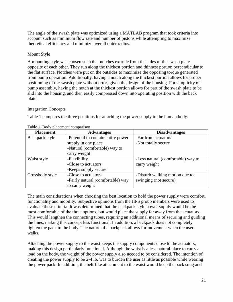
Integration Concepts
Table 1 compares the three positions for attaching the power supply to the human body.
Table 1. Body placement comparison
Placement Advantages Disadvantages
Backpack style -Potential to contain entire power
supply in one place
-Natural (comfortable) way to
carry weight
-Far from actuators
-Not totally secure
Waist style -Flexibility
-Close to actuators
-Keeps supply secure
-Less natural (comfortable) way to
carry weight
Crossbody style -Close to actuators
-Fairly natural (comfortable) way
to carry weight
-Disturb walking motion due to
swinging (not secure)
The main considerations when choosing the best location to hold the power supply were comfort,
functionality and mobility. Subjective opinions from the HPS group members were used to
evaluate these criteria. It was determined that the backpack style power supply would be the
most comfortable of the three options, but would place the supply far away from the actuators.
This would lengthen the connecting tubes, requiring an additional means of securing and guiding
the lines, making this concept less functional. In addition, a backpack does not completely
tighten the pack to the body. The nature of a backpack allows for movement when the user
walks.
Attaching the power supply to the waist keeps the supply components close to the actuators,
making this design particularly functional. Although the waist is a less natural place to carry a
load on the body, the weight of the power supply also needed to be considered. The intention of
creating the power supply to be 2-4 lb. was to burden the user as little as possible while wearing
the power pack. In addition, the belt-like attachment to the waist would keep the pack snug and

22
secure against the body. The belt-like attachment also allows the power supply to be distributed
around the waist if necessary.
Wearing the power supply in a crossbody fashion is functional by putting the supply near the
actuators, and is a fairly comfortable way to carry a load. The main downfall of this concept is
that the inherent motion of a crossbody bag is to swing while the user walks. This function could
impede the users stride or cause the user to become unbalanced.
The analysis of each body location concluded that attaching the power supply to the waist was
the best concept. It is functional in terms of its location relative to the actuators. It is also
functional for flexibility in the design because the entire circumference of the waist can be used
if necessary. In addition, this type of attachment allows the pack to remain securely fastened to
the user, prohibiting any movement of the supply. The potential for the placement to be
uncomfortable can be negated by the fact that the power supply will be particularly light weight.
Table 2 compares the component configuration options, shown in Figures 5-7, which will be
located at the waist of the user.
Table 2. Component configuration comparison
Concept Advantages Disadvantages
1 -Compact -Check valves not near reservoir
2 -Distributes weight -Elongates overall integration
3 -Utilizes the reservoir as a heat sink
-Compact
-Complex
Size, weight, and functionality were the main criteria for evaluating each initial configuration
concept. The ideal design would be as compact and as light weight as possible while maintaining
the desired functionality of each component. Although Concept 1 was a compact design, a better
design would have the check valves near the reservoir to eliminate unnecessary fluid lines.
The reservoir’s weight is fixed, based on the volume of fluid in the power and actuator package.
Since there is no way to optimize or minimize this weight, it is advantageous then to utilize the
reservoir for a secondary function. In Concept 2 the reservoir would help balance the power
supply by distributing weight. The motor and gear box will be over half the weight of the entire
integrated system. Using the reservoir to offset this weight would increase the power supply’s
stability and evenness. Concept 2 also introduces manifold style housing for the power supply.
As Figure 6 shows, the inlet and outlet lines run through the reservoir.
Concept 3 utilizes the reservoir as a heat sink for the pump. This is advantageous because an
axial piston pump has three main interfaces where viscous friction causes the pump to heat up
during usage [19]. This design is also compact, mimicking the shape of the pump, and creating a
close-fitting configuration.
The final concept was a combination of Concept 2 and 3, shown in Figure 19.

23
Figure 19. Final integration concept
The design uses a manifold block system [15], which contains the entire circuit inside the block.
Typical manifold block systems are rectangular with ports to insert screw-in cartridge valves and
internal fluid passageways [15]. This design is a custom shape to eliminate any excess material
(weight) not directly used in transporting the fluid. The red faces represent where the regular and
pilot-operated check valve cartridge would screw in. The turquoise faces indicate fluid lines, and
the blue face represents the pump insert. In addition, the solid material between the pathways has
been removed and this space has been used as the reservoir, shown in Figure 20.
Figure 20. Section view looking at one half

24
The purple faces show boundaries of the reservoir. This incorporates the balancing feature of
Concept 2 and the heat sink feature of Concept 3. In general, the manifold block system allows
the design to size the integration in the most efficient way possible. Figure 21 looks through the
manifold’s front face, illustrating the inner configuration and compactness.
Figure 21. Internal pathways
Note that this model illustrated the concept that was initially intended to be used. Figures 22-24
show various versions of the manifold configuration. Designing the manifold was a continuous
process throughout the project to incorporate design changes and maximize compactness.
Figure 22. Manifold version 1

25
Figure 23. Manifold version 2
Figure 24. Manifold version 3
The final design is based off of version 3, shown in Figure 24. Appendix C shows detailed
drawings of the finalized manifold configuration.

26
Solenoid Valves
The custom designed valve is shown in Figure 25.
Figure 25. Section view of designed solenoid valve
The main strengths of the designed valve were the low power consumption of 2.48 W and the
high pressure at which it was capable of operating, 2000 psi. The main weaknesses of the design
were the weight and size of the valve. According to calculations performed in Creo, the valve’s
weight was around 3.6 lb., which would put the overall weight of the HPS well over the
maximum allowed limit shown in Volume I Table 1. In addition, the designed valve was larger
than desired at a length of 3 inches. Table 3 compares the key specifications of the custom
designed valve to The Lee Company’s valve, part number SDBB3321003A.
Table 3. Summary of two solenoid valve options
Parameter Solenoid valve from the Lee
Company
Custom designed solenoid
valve
Weight (lbs) 0.15 3.6
Maximum operating pressure (Pa) 3,000 2,000
Power consumption (W) 7.8 2.48
Overall Length (in) 1.88 3
Outside Diameter (in) 1 3.1
Voltage (V) 28 24
Current (A) 0.28 0.103
The designed valve was more than 20 times the weight of The Lee Company’s valve and almost
twice as long. Both valves operate at 2000 psi or greater, but the designed valve consumes half
of the rated power needed to operate The Lee Company’s valve. It was decided that the extra

27
power required by the Lee valves was less of drawback than the excessive weight of the custom
designed valve. The Lee Company’s valve was chosen to be included in the HPS design.
The difference in the weight and size of the two valves is attributed to the principle of operation.
While the designed valve is a direct acting solenoid valve, the Lee valve is a pilot operated
solenoid valve. This means that it operates in two stages; which allow the solenoid to be smaller
and lightweight. From the weight calculations of the custom designed valve, it was noted that
about 90% of the weight lies in the weight of the coils. Based on this, it is clear that in order to
design a lighter and smaller solenoid valve, the piloting principle must be applied.
2 Design Description Supporting Documents
2.1 Manufacturing Plan
2.1.1 Manufacturing Overview
The manufacturing of the HPS begins with precision machining of the pump components which
will be made from AISI 4130 steel, normalized at 870 C. These pump components include 5
pistons, 5 slippers, the cylinder barrel, swash plate, and the valve plate. The manifold and
manifold cover will be additively manufactured out of alsi10mg aluminum. The attachment
brackets for the manifold and battery will be injection molded using polypropylene
homopolymer material. Injection molding will be utilized due to the unique shape of the brackets
as well as ease of injection molding with polypropylene. However, injection molding is generally
used to produce parts in mass and is therefore not a practical manufacturing method for the
prototype. For the prototype, it is suggested that the brackets be constructed out of raw
polypropylene purchased from a supplier such as McMaster Carr. Major components which will
be purchased, include the battery, DC motor, gear box, pilot operated check valves and solenoid
valves. The gearhead will need to have an extension welded onto the shaft in order to be able to
be properly inserted into the cylinder barrel. Given that the shaft hole in the cylinder barrel is
larger than the gearhead shaft, this will allow for a simpler process of welding on the extension.
This will then be finished with a lathe and/or mill. Some minor components which will be
purchased include the piston springs, aluminum plugs, shaft seal, tubing and screws.
2.1.2 Part Drawings
Please see Appendix C for detailed part drawings of every component in the HPS.

28
2.1.3 Bill of Materials
Table 4. Bill of materials
Item Description Part Number Quantity Total Cost Total Weight
(lbs)
Battery ZIPPY Compact 3700mAh 6S 25C Lipo Pack ZC.3700.6S.25 1 $ 45.49 1.110
DC Motor Maxon Motor, EC 45 flat 397172 1 $ 160.50 0.311
Gearhead Maxon Motor, planetary gearhead GP 32 C 166930 1 $ 175.25 0.260
Pump - Piston machined from 1/2" steel rod, AISI 4130 Steel, normalized at 870C
Custom 5 $ - 0.033
Pump - Slipper machined from 1/2" steel rod, AISI 4130 Steel,
normalized at 870C Custom 5 $ - 0.012
Pump - Spring The Lee Company, stainless steel CIM025D 06 S 5 $ 31.80 0.006
Pump - Cylinder
Barrel
machined from 1.25" steel rod, AISI 4130 Steel,
normalized at 870C Custom 1 $ - 0.124
Pump - Swash
Plate
machined from 1.25" steel rod, AISI 4130 Steel,
normalized at 870C Custom 1 $ - 0.063
Pump - Valve
Plate
machined from1.25" steel rod, AISI 4130 Steel,
normalized at 870C Custom 1 $ - 0.037
Manifold Additive manufactured aluminum - alsi10mg Custom 1 $ - 1.486
Manifold Cover Additive manufactured aluminum - alsi10mg Custom 1 $ - 0.131
Pilot-Operated Check Valve
The Lee Company, Ø .281" Pilot Operate Chek CPRA2506005A 2 $ 1,814.34 0.023
Solenoid Valve The Lee Company, 2-way high flow piloting solenoid
valve SDBB3321003A 2 $ 3,223.54 0.300
Plug The Lee Company, Ø .281" aluminum plug, short style PLGA2810010A 2 $ - 0.004
Hose 1ft Goodridge, PTFE smooth bore, stainless steel overbraid
600-03 6 $ 14.64 0.240
Hose Fitting Goodridge, Straight Male Convex Seat Reusable JIC,
aluminum 441-03D 2 $ 49.14 0.044
Manifold Cover Bolts
Fastenal 1/4"- 20 x 0.75" Aluminum Hex Cap Screw 76310 4 $ 1.64 0.026
Gearhead Bolts Fastener Express M3 x .5 x 10mm Aluminum Flat Head
Socket Screw FHM3010-3G3 4 $ 0.76 0.002
Shaft Seal McMaster-Carr Spring-Loaded PTFE Shaft Seal, 1/4" Shaft, 3/8" OD
13125K65 1 $ 9.85 0.001
O-ring McMaster-Carr Buna-N O-Ring, AS568A Dash No. 025 9452K78 1 $ 0.06 0.001
Attachment
Bracket -
Manifold
McMaster-Carr 12"x12" 1/8" Thick Opaque White Polypropylene Sheet
2898K11 1 $ 4.20 0.044
Attachment Bracket Screws
Fastener Express M3 x .5 x 8mm Aluminum Flat Head Socket Screw
FHM3008-3G3 4 $ 0.72 0.002
Attachment
Holder - Battery
McMaster-Carr 12"x12" 1/8" Thick Opaque White
Polypropylene Sheet 2898K11 1 $ 4.20 0.058
Total $ 5,536.13 4.316
Total Weight Less Hose & Fitting 4.032
2.1.4 Manufacturing Procedure
The manufacturing procedure references the Exploded Assembly Drawing #100, shown in
Appendix C.
1. Attach hoses [14] to JIC male fittings [15]
a. The fittings are reusable. Follow manufacturer instructions to securely fasten
hoses [14] to fittings [15]
2. Screw JIC male fittings [15] into threaded holes in bottom of manifold [17]

29
3. Insert pump into pump cavity in manifold [17] in the following order:
a. Valve plate [5] (align notches with manifold [17])
b. Cylinder block [3]
c. Pistons [1] into cylinder block [3]
i. Press fit slippers [2] onto piston [1] before inserting into cylinder block [3]
ii. Put springs [6] into pistons [1] before inserting into cylinder block [3]
d. Swash plate [4] (align notches with manifold [17])
4. Insert pilot operated check valves [20] into manifold [17] aligning side port with line
opening.
a. Insert check pin [21] into check valve [20], following The Lee Company’s insert
instructions
5. Insert aluminum plugs [22] above pilot operated check valves [20] into manifold [17].
a. Insert aluminum pin [23] into plug [22], following The Lee Company’s insert
Instructions
6. Place O-ring [7] into appropriate spot in manifold cover [16]
7. Insert shaft seal [8] into appropriate hole in manifold cover [16]
8. Attach gearhead [25] / dc motor [19] to manifold cover [16]
a. Gearhead [25] comes press fitted into motor [19] from Maxon
b. Align holes in gearhead [25] and manifold cover [16]
c. Use 2.5mm hex key to insert gearhead bolts [10] into counter sunk holes of
manifold cover [16]
9. Attach manifold cover [16] with attached gearhead [25] and motor [19] to manifold [17]
a. Align shaft of gearhead [25] to cylinder barrel [3] center hole and insert
b. Use 7/16” wrench to insert manifold cover bolts [9] into clearance holes in
manifold cover [16] and into manifold [17]
c. As the manifold cover screws are tightened, axial piston pump will be compressed
into the pump cavity
10. Screw solenoid valves [24] into manifold [17]
11. Screw manifold bracket [12] to manifold [17]
a. Align holes in manifold bracket [12] and manifold [17]
b. Use 2.5mm hex key to insert manifold bracket screws [11]
12. Place battery [18] in battery case [13]

30
3 Evaluation Supporting Documents Table of Contents
3.1 Evaluation Reports
Structural Integrity – Manifold
Introduction
The purpose of this experiment was to determine whether the manifold for the HPS could
withstand the internal pressures experienced during its use. The importance of ensuring the
structural integrity of the manifold is twofold. If an internal line was to burst, or if material broke
off and entered the fluid flow, this would be detrimental to the system’s operation and would
perhaps destroy other equipment in the hydraulic circuit. The manifold’s structural integrity is
also important to the user’s safety. Pressurized fluid as high as 2000 PSI will be passing through
the manifold. If part of the manifold burst at this pressure, shrapnel and high velocity fluid could
injure the user. Since the manifold will experience fluctuating pressures, it was necessary to
perform fatigue analysis. The manifold’s geometry was modeled in SolidWorks and then
uploaded to ANSYS—a finite-element analysis software package. Results obtained from the
simulation conducted in ANSYS include von Mises stress, total deformation, and expected life at
each node. These three results provide insight as to where the stresses are concentrated, how
much the model deformed, and how long the manifold will last.
Methods
The geometry was modeled in SolidWorks which is compatible with ANSYS. This file was then
imported into ANSYS Workbench’s Static Structural module. A custom material had to be
created in ANSYS’s Engineering Data Sources since the 3D-printed metal (Aluminum
AlSi10Mg) was not listed. The properties of AlSi10Mg are listed in Table 5. It should be noted
that the S-N curve was taken from a pre-existing entry (aluminum alloy).
Table 5. Aluminum AlSi10Mg properties
Property Value Unit
Density 2670 kg/m^-3
Tensile Yield Strength 250 MPa
Compressive Yield Strength 280 MPa
Tensile Ultimate Strength 420 MPa
Young’s Modulus 69000 MPa
Poisson’s Ratio 0.33 --
A body-sized mesh of 3 mm was placed onto the manifold. A face sizing of 0.75 mm was placed
on the walls of tubes that would experience pressure in excess of ambient. This was done since
these areas will experience large stress gradients, and it is important to capture the effects of
these stresses. 218,000 nodes and 143,000 elements were placed onto the manifold. The

31
educational version of ANSYS is limited in the number of nodes which can be placed, so an
effort was made to maximize this number. A cross section of the mesh is shown in Figure 26.
Figure 26. Manifold mesh
The manifold’s tubes will experience various pressures during a cycle. The exact pressures in
each tube during every point in the cycle have yet to be determined. From preliminary simulation
data obtained by the CCEFP, it is known that the maximum pressure during the cycle will be
2000 PSI and the minimum will be slightly below ambient pressure. As a worst case scenario, a
zero-based fatigue condition with amplitude of 2000 PSI was applied to all lines which will
experience significant pressure. The lines which experienced this pressure are highlighted in red
in Figure 27. Also shown are the fixed supports in green. This is a logical location since this is
where the bolts hold the cover to the manifold.
Note: High node density near along pressurized tube wall.
Note: High node density along pressurized tube wall

32
Figure 27. Pressurized tubes
Before running the simulation, a total deformation and equivalent stress plot were added. The
equivalent stress plot was set to show von Mises stress. von Mises stress is the equivalent
uniaxial stress that would produce the same level of distortion energy as the actual stresses
involved. According to the maximum-distortion-energy theorem, if the von Mises stress exceeds
the material’s yield strength, yielding will occur; if the von Mises stress exceeds the material’s
ultimate strength, complete failure will occur. This is only valid for static loads. Since von Mises
stress is an equivalent uniaxial stress, data taken for uniaxial fatigue can be used to determine the
life of the manifold. A plot was added showing life of the material at each given node.
Goodman’s mean stress theory was chosen as the fatigue failure criteria. This theory plots lines
of constant life (Goodman lines) on a plot of alternating stress vs. mean stress. The Goodman
line of the alternating and mean stress plot is then used to determine the life of the material
element. A notable aspect of Goodman’s theory is that the material may exceed the yield strength
during its cycle, but it will never exceed the ultimate strength. Aluminum alloys do not typically
have an endurance limit so infinite life can never be expected. The best that can be done is to
determine the minimum life. To determine how long the manifold will last, the length of one
cycle (one human step) was set equal to one second.
Results
The plots of equivalent stress for various cross sections are shown in Figures 28-30. These show
the equivalent stresses when there is 2000 PSI applied to the tube walls. Most of the tube walls
appear green which mean the stresses are approximately 30 MPa. The max stress of the entire
manifold is shown in Figure 29 with a magnitude of 61.7 MPa. The minimum safety factor of the
manifold was found to be roughly 4. This is simply the yield strength divided by the maximum
stress in the part. Figures 31-33 show the total deformation for various cross sections. The
maximum deformation occurs in Figure 33 in the pilot-operated check-valve cavity. This
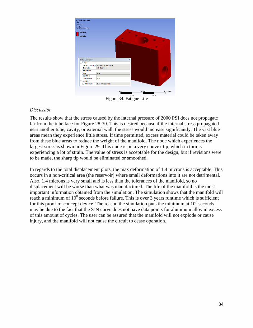
deformation is approximately 1.4 microns. The fatigue life plot is shown in Figure 34. It can be
seen that the minimum life expected for the part is 108 seconds or a little over 3 years runtime.

33
Figure 28. Equivalent Stress Cross Section 1 Figure 29. Equivalent Stress Cross Section 2
Figure 30. Equivalent Stress Cross Section 3 Figure 31. Total Deformation Cross Section 1
Figure 32. Total Deformation Cross Section 2 Figure 33. Total Deformation Cross Section 3
34
Figure 34. Fatigue Life
Discussion
The results show that the stress caused by the internal pressure of 2000 PSI does not propagate
far from the tube face for Figure 28-30. This is desired because if the internal stress propagated
near another tube, cavity, or external wall, the stress would increase significantly. The vast blue
areas mean they experience little stress. If time permitted, excess material could be taken away
from these blue areas to reduce the weight of the manifold. The node which experiences the
largest stress is shown in Figure 29. This node is on a very convex tip, which in turn is
experiencing a lot of strain. The value of stress is acceptable for the design, but if revisions were
to be made, the sharp tip would be eliminated or smoothed.
In regards to the total displacement plots, the max deformation of 1.4 microns is acceptable. This
occurs in a non-critical area (the reservoir) where small deformations into it are not detrimental.
Also, 1.4 microns is very small and is less than the tolerances of the manifold, so no
displacement will be worse than what was manufactured. The life of the manifold is the most
important information obtained from the simulation. The simulation shows that the manifold will
reach a minimum of 108 seconds before failure. This is over 3 years runtime which is sufficient
for this proof-of-concept device. The reason the simulation puts the minimum at 108 seconds
may be due to the fact that the S-N curve does not have data points for aluminum alloy in excess
of this amount of cycles. The user can be assured that the manifold will not explode or cause
injury, and the manifold will not cause the circuit to cease operation.

35
Structural Integrity - Pump
Introduction
A pump is one of the key components of any hydraulic system. For the power supply, an axial
piston pump has been chosen to fulfill the necessary pumping requirements of the design. An
axial piston pump is a positive displacement pump that has a number of pistons in a circular
array within a cylinder block. The pump is powered by an external power source such as a DC
electric motor as will be implemented with the HAFO design. An axial piston pump offers a
small and compact system, which is capable of a wide range of operating pressures and output
flows when properly designed. The axial piston pump for the power supply has been designed to
be smaller than any other axial piston pump available in the hydraulic industry. The pump was
designed to be capable of operating at peak pressures of 2000 psi, and to have an output flow of
~0.4 cc/rev at a shaft speed of 1500 rpm. It was necessary to evaluate the structural integrity of
the pump to determine whether the pump structure will be able to withstand peak operating
pressures of 2000 psi.
Methods
Analysis was carried out to determine whether the maximum determined stresses that occur
within the individual components of the pump are significantly above safe operation of the
material. Additionally, the maximum deformations that occur within the components were
observed to see if they were within allowable operating conditions.
To evaluate the individual components that compromise the axial piston pump system the finite-
element analysis software suite, ANSYS, was used. To begin, the components were designed to
their specific dimensions in a 3D CAD design software suite, SolidWorks. Upon completion of
the 3D CAD designs, the individual components were then imported into ANSYS software for
finite-element analysis of the components’ structural integrity.
Within the software, everything was treated as a static system for simplicity of analysis. An
equally distributed pressure of 2000 psi was applied to the faces of the geometries which are
exposed to the maximum operating pressure of the hydraulic fluid. An equally distributed
pressure of 2000 psi represents the worst case scenario in analysis where every face is exposed to
the peak operating pressure. This allows for a safe overestimate of the structural integrity.
Proper constraints and supports were added to each component before completing the analysis, to
accurately model the fixture conditions of the components. An analysis was then performed on
each of the components to observe the maximum stresses and deformations within the
components. All of the materials were assigned to be AISI 4130 (normalized at 870C).
The maximum stresses were compared to the yield stress of AISI 4130 to determine whether the
component would fail and to determine the safety factor for which the component’s structure is
designed. Additionally the maximum stress was observed on an S-N curve. This was done to
determine whether the material would be capable of safely operating for infinite life, or whether
fatigue would occur at the stresses the components exhibited.

36
Finally, the deformations were observed to determine whether the deformations were within the
allowable deformable distances for the component structure for effective and efficient pumping.
Results
This section will show the results of the finite element analysis which was performed on the
individual components using ANSYS.
Figures 35 and 36 show a visualization of the maximum stresses and deformations that occur
within the valve plate.
Figure 35. Valve plate - equivalent (von Mises stress) stress (psi)
Figure 36. Valve plate - total deformation (in)

37
Figures 37 and 38 show a visualization of the maximum stresses and deformations that occur
within the cylinder barrel.
Figure 37. Cylinder barrel - equivalent (von Mises stress) stress (psi)
Figure 38. Cylinder barrel - total deformation (in)

38
Figures 39 and 40 show a visualization of the maximum stresses and deformations that occur
within the piston.
Figure 39. Piston - equivalent (von Mises stress) stress (psi)
Figure 40. Piston - total deformation (in)

39
Figures 41 and 42 show a visualization of the maximum stresses and deformations that occur
within the slipper.
Figure 41. Slipper - equivalent (von Mises stress) stress (psi)
Figure 42. Slipper - total deformation (in)

40
Figures 43 and 44 show a visualization of the maximum stresses and deformations that occur
within the swash plate.
Figure 43. Swash plate - equivalent (von Mises stress) stress (psi)
Figure 44. Swash plate - total deformation (in)
Table 6 lists the maximum stresses that each of the components exhibited. Additionally, a safety
factor was calculated based on the AISI 4130 (normalized at 870C) yield strength compared to
the components’ maximum stresses.
Table 6: Maximum Stresses
Component Material Yield Strength (psi) Maximum Stress (psi) Safety Factor
Valve Plate AISI 4130 Steel, normalized at 870C 66,717 9132 7.305847569
Cylinder Barrel AISI 4130 Steel, normalized at 870C 66,717 3593 18.56860562
Piston AISI 4130 Steel, normalized at 870C 66,717 2836 23.52503526
Slipper AISI 4130 Steel, normalized at 870C 66,717 5359 12.44952416
Swash Plate AISI 4130 Steel, normalized at 870C 66,717 43503 1.533618371

41
Figure 45 shows the fully reversed axial S-N curve for AISI 4130 Steel, which can be used to
determine whether each of the components would be capable of safely operating for infinite life,
or whether fatigue would occur at the stresses the components exhibited.
Figure 45. Fully reversed axial S-N curve for AISI 4130 steel
Table 7 lists the maximum stresses that each of the components exhibited and the stress at which
AISI 4130 will be capable of sustaining infinite life. Additionally, a safety factor is calculated.
Table 7. Infinite life stress comparison
Table 8 lists the maximum deformations that occur within each component. Additionally, a
safety factor is calculated based on the allowable deformation for each component.
Table 8. Maximum deformation
Component Material Infinite Life (psi) Maximum Stress (psi) Safety Factor
Valve Plate AISI 4130 Steel, normalized at 870C 49,000 9132 5.365746824
Cylinder Barrel AISI 4130 Steel, normalized at 870C 49,000 3593 13.63762872
Piston AISI 4130 Steel, normalized at 870C 49,000 2836 17.27785614
Slipper AISI 4130 Steel, normalized at 870C 49,000 5359 9.143496921
Swash Plate AISI 4130 Steel, normalized at 870C 49,000 43503 1.126359102
Component Material Allowable Deforamation (μ-in) Maximum Deformation (μ-in) Safety Factor
Valve Plate AISI 4130 Steel, normalized at 870C 1,000 17.14 58.34305718
Cylinder Barrel AISI 4130 Steel, normalized at 870C 26 8.2505 3.151324162
Piston AISI 4130 Steel, normalized at 870C 26 5.3873 4.82616524
Slipper AISI 4130 Steel, normalized at 870C 1,000 15.314 65.29972574
Swash Plate AISI 4130 Steel, normalized at 870C 1,000 25.487 39.23568878

42
Discussion
Looking at Table 6, no maximum stress that occurred within each of the components during the
finite element analysis was above the yield strength of the component’s material, AISI 4130
Steel (normalized at 870C). A minor discrepancy occurred within the simulation for the swash
plate, as the analysis reported a maximum stress of ~43.5 ksi. However, this maximum stress
occurred at a location that is not of concern, on a micro-inch scale. The rest of the of the swash
plate only experienced a maximum stress of ~64 psi, which is significantly below the yield
strength of the material. Neglecting the discrepancy that occurred within the swash plate
simulation analysis, the smallest safety factor was ~7, which confirms that the pump will operate
within safe stresses to a high safety factor.
Looking at Table 7, no maximum stress that occurred within each of the components during the
finite element analysis with ANSYS was above the infinite life stress of the component’s
material, AISI 4130 Steel (normalized at 870C). Again, the minor discrepancy exists for the
swash plate at a maximum stress of ~43.5 ksi being reported from the ANSYS analysis
simulation. As mentioned earlier, this maximum stress occurred at a location that is not of
concern, on a micro-inch scale. The rest of the of the swash plate only experienced a maximum
stress of ~64 psi, which is significantly below the infinite life stress of the material. Neglecting
the discrepancy that occurred within the swash plate simulation analysis, the smallest safety
factor was ~5. This confirms that the material used for the components in the pump will not
suffer from fatigue resulting from cyclical loading, but rather will have an infinite life.
Finally, looking at Table 8, no maximum deformation that occurred within each of the
components during the finite element analysis with ANSYS was greater than the maximum
allowable deformation distance for effective and efficient pump operation. No obvious
discrepancies existed during this simulation analysis, resulting in the smallest safety factor of ~3.
This confirms that the pump will be able to theoretically operate effectively and efficiently
without deformations caused by high operating pressures being of concern.
Upon analyzing the results of the simulation performed with ANSYS software, and comparing
them to the known material properties of the individual components, AISI 4130 Steel
(Normalized at 870C), it can be concluded that the pump will be able to operate for an infinite
life. The minor deformations caused by high operating pressures will not be of concern for
effective and efficient pumping.

43
Pump Performance (Efficiency) and Max Flow Rate
Introduction
The pump used in the HPS must be very small and compact, while remaining very efficient. A
MATLAB code was developed in order to optimize a very small hydraulic pump while
maintaining the necessary performance and the highest efficiency possible.
Methods
A MATLAB function was written as a tool to find an optimized design for the axial piston pump
in the HPS. A secondary function of the program was to output a graphic to give the designer an
idea of what the final product would look like. The parameters to design for were the piston
radius, the barrel radius, the pitch radius, the swash plate angle, and the number of pistons. The
variable names for these values were prad, brad, pitch, α, and numpist. Equations of physical
constraints were found in order to find the possible pump parameters. Specifically, formulas
were derived for the distance between the pistons and the distance between the piston and the
wall as functions of the design variables. These variables are pgap and thickness, respectively, and
were found to be:
√ ( ( )) (5)
(6)
These values were determined through reverse engineering of current pumps as pdist>0.14 inches
and thickness>0.07 inches. Another physical constraint to be considered is the central shaft that
connects the pump to the motor. This value needed to be greater than 0.25 inches and was found
by differencing the pitch and piston radius. The code iterates through values for the physical
variables of the pump and checks if they are physically possible using the constraints. Each
physically possible value is saved, and the volume and efficiency are calculated for the
theoretical pump. The volume is calculated as a function of the physical variables.
( ( )) (7)
This formula assumes that the cylinder barrel is solid, with the piston bores being filled by the
pistons. It uses a barrel length of 0.84 inches, determined by reverse engineering the other
pumps. The second part of the sum is an equation for the volume of the swash plate. It is the
equation for a cylinder with a height of tan(α) + 1/32 inches. The efficiency was found using a
MATLAB function developed by Jicheng Xia [13]. It was then updated to better suit the needs of
the HPS design. The efficiency takes into account losses through leakage and friction. The
volume and efficiency are stored in arrays with a location respective to the physical parameters
that created those results. A scatter plot of efficiency with respect to volume is then created, and
the user can select any point to find the physical parameters that created it as well as the power
requirements, shaft speed, and torque needed to produce maximum output.
( ( )
) (8)

44
Qvp is the volumetric flow rate, set as 11 cc/s for the maximum output needed to run HAFO. Ap
is the cross sectional area of the piston. The torque is calculated through the following formula:
( )
(9)
P is the operating pressure. The power is calculated as the product of the shaft speed and the
torque.
Results
The code outputs two figures. One is a scatter plot of all the physically possible pumps, showing
efficiency with respect to the volume. The other is a top-view graphic of the pump along with a
parameter box showing useful pump parameters. Figures 46 and 47 show these outputs.
Figure 46. Scatter plot of possible pumps
Any of these points can be selected by the user to show the graphic representation and output
requirements of the pump.

45
Figure 47. Graphic representation of a selected point
The design point show in Figure 47 was the selection for the axial piston pump. This was the
result of selecting the point with a volume of 0.82 cubic inches and an efficiency of 0.799. The
pump displacement, shaft speed, torque, power, efficiency, and all the design variables are
shown in the lower left-hand box.
Up to that point, increasing the volume greatly increases the efficiency, but the gains diminish
after this point. The pump is still very small and almost 80% efficient. This point was made by
having prad = 0.106 in, brad = 0.480 in, pitch = 0.3 in, α = 15°, and numpist = 5. The required shaft
speed is 1419.4 rpm, required shaft torque is 9.95 lb-in or 1.124 Nm, and the required power is
167.1 W. This is the maximum output requirement for the HAFO and is only required for a very
brief moment during a walking cycle.
Discussion
This design for an axial piston pump provides the necessary output while being very compact
and efficient. It is less than 1 cubic inch. The goal for efficiency was over 20% and the
theoretical efficiency is almost quadruple that. The MATLAB code provided a highly optimized
design and provided important information that were used for such design choices as motor
selection, battery selection, and hydraulic circuit design. This choice will provide a very compact
and comfortable hydraulic power supply to patients who need a powered ankle-foot orthosis.

46
Total Weight
Introduction
The weight of each component was a major consideration when making design choices for the
hydraulic power supply. Many of the design choices overlapped, making it especially important
to choose the component that weighed the least without compromising other requirements. The
total weight of the completed design was evaluated to determine the load the wearer of the
HAFO will have to bear.
Methods
Manufacturer data provided the weight of components that are intended to be purchased. For the
custom designed parts, material densities were assigned in the Solid Works models and the
analysis feature was used to calculate the weight. Table 9 outlines the designed part’s material
and density properties.
Table 9. Material properties for custom designed parts
Item Material Density ( )
Pump AISI 4130 steel, normalized at 870C 0.284
Manifold alsi10mg aluminum 0.096
Manifold cover alsi10mg aluminum 0.096
Attachment bracket – manifold Polypropylene 0.034
Attachment holder – battery Polypropylene 0.034
The material for the manifold and manifold cover is a specific type of aluminum used in additive
manufacturing. The individual weights were then combined to get a total HPS weight.
Results
Table 10 shows an itemized weight contribution for each part, the source that provided the
weight value and the total combined weight.
Table 10. Itemized weight evaluation
Items Quantity Unit Weight
(lb.)
Total Weight
(lbs) Source
Battery 1 1.110 1.110 Hobby King
DC Motor 1 0.311 0.311 Maxon Motor
Gearhead 1 0.260 0.260 Maxon Motor
Pump - Piston 5 0.007 0.033 SolidWorks
Pump - Slipper 5 0.002 0.012 SolidWorks
Pump - Spring 5 0.001 0.006 SolidWorks
Pump - Cylinder Barrel 1 0.124 0.124 SolidWorks
Pump - Swash Plate 1 0.063 0.063 SolidWorks
Pump - Valve Plate 1 0.037 0.037 SolidWorks
Manifold 1 1.486 1.486 SolidWorks

47
Manifold Cover 1 0.131 0.131 SolidWorks
Pilot-Operated Check Valve 2 0.012 0.023
The Lee
Company
Solenoid Valve 2 0.150 0.300
The Lee
Company
Plug 2 0.002 0.004
The Lee
Company
Hose 6 0.040 0.240 Goodridge
Hose Fitting 2 0.022 0.044 Goodridge
Manifold Cover Bolts 4 0.006 0.026 Fastenal
Gearhead Bolts 4 0.001 0.002
Fastener
Express
Shaft Seal 1 0.001 0.001 McMaster-Carr
O-ring 1 0.001 0.001 McMaster-Carr
Attachment Bracket - Manifold 1 0.044 0.044 McMaster-Carr
Attachment Bracket Screws 4 0.000 0.002
Fastener
Express
Attachment Holder - Battery 1 0.058 0.058 McMaster-Carr
Total 4.316
Total Weight Without Hose &
Fitting 4.032
From Table 10, including the hoses and fittings, the total weight of the HPS is 4.316 pounds.
Considering the hoses can be disconnected from the HPS via the fittings, it was appropriate to
consider the total HPS weight without these pieces as well. The total weight of the HPS is then
4.032 lb.
Discussion
4.032 lb. is slightly greater than the upper limit of the allowable weight range of 2-4 lb. The
largest contributors to the weight were the battery and manifold. The battery was sized for
10,000, but would decrease in weight as the lifespan decreased. Unless components are removed
from the circuit, the manifold’s weight cannot be easily changed. Considering the deliverable is a
virtual prototype, the components of the power supply were not purchased and/or machined.
Thus, at this time, the total weight is theoretical.

48
Total Size/Comfort
Introduction
One of the important considerations for the HPS was how to make it comfortable for the
user to wear daily for an extended period of time. This meant that it would need to be made as
small and compact as possible, while minimizing the protrusion from the body. It also needed to
not interfere with walking and sitting. Initial evaluation led to the placement of the supply at the
user’s waist. To evaluate this placement, a mock-up was created that had the same shape, size,
and weight as the real power supply would.
Methods
The first step in creating a comfortable power supply was to evaluate the different locations the
power supply could be placed. The placements looked at were a backpack style, waist style and
crossbody style. These were simulated with bags of different styles secured at the given location.
The styles were evaluated for potential advantages and disadvantages, such as the length of
hydraulic lines, while keeping in mind the user’s comfort. This led to the selection of the waist
style for placement. The style that appeared most advantageous and comfortable was the
placement at the user’s waist along the side of their leg.
The next step was to further test the waist style by creating a mock-up. It was necessary to wait
until the power supply dimensions and weight were finalized. This would allow for the creation
of an accurate mock-up that simulated the weight, size and shape of the actual power supply. The
components were mocked up as a cardboard shell. To accurately simulate the weight of the
components, washers and sugar were added inside of the manifold, motor, gearbox and battery
cardboard shells. These were weighed on a scale to ensure the accuracy. To allow for it to be
worn, the brackets were also mocked-up and secured to the HPS and battery. This allowed them
to be attached to the user’s belt. The HPS (manifold, motor, gear box and mounting bracket) as
well as the battery with mounting bracket mock-ups are shown below in Figures 48 and 49,
respectively.
Figure 48. Manifold, motor, gearbox and
mounting bracket mock-ups
Figure 49. Battery and mounting bracket mock-
up

49
This mockup was then worn by each member of the group, and their opinions on the comfort
level were taken informally. This was deemed satisfactory, as the goal for comfort in this project
was to design so that the group members would find the HPS comfortable.
Results
The results of the body placement evaluation from the concept selection section of the report are
repeated in Table 11.
Table 11: Body placement comparison
Placement Advantages Disadvantages
Backpack style -Potential to contain entire power
supply in one place
-Natural (comfortable) way to
carry weight
-Far from actuators
-Not totally secure
Waist style -Flexibility
-Close to actuators
-Keeps supply secure
- Does not impede natural leg
movement
-Less natural (comfortable) way to
carry weight when unsecured
Crossbody style -Close to actuators
-Fairly natural (comfortable) way
to carry weight
-Disturb walking motion due to
swinging (not secure)
This analysis was used to determine that the waist style was the best choice.
Upon wearing the mock-ups, every member of the group found the power supply to be
comfortable. The battery was attached to the opposite hip and it was agreed that it would be
successful in helping to balance some of the weight. Protrusion of the HPS was minimal which
was found to be a positive while walking. Also, the swaying of the HPS was very minimal and
made it feel secure.
Discussion
Due to the fact that comfort was evaluated by the HPS group members, it was important to keep
in mind that this may not represent the general public. Healthy, young people are not necessarily
who would be wearing the HPS. A total weight of roughly four pounds added on to the body
would almost certainly be more of a burden on someone with muscle impairments. Fortunately,
the HPS mock-up proved to be comfortable, secure, and reasonable to be worn when tested by
members of the HPS group.

50
3.2 Cost Analysis
The HPS is a proof-of-concept design. The mindset was to develop the HPS on a single unit
basis, rather than as a product that could be mass produced. The main user for the HPS is the
CCEFP. For this reason, cost was not a main concern for the project, but costs were kept to a
minimum whenever possible. A major cost challenge was the solenoid valve and pilot operated
check valve. The Lee Company solenoid valves that were selected for the HPS are extremely
expensive, costing $1611.77 for one. Because of this, an effort was made to design custom
solenoid valves. This resulted in valves that were much heavier than the Lee Company’s. Despite
their cost and high power consumption, the Lee Company’s solenoid valves were selected due to
their tiny size. The solenoid valves selected from the Lee Company are also very expensive, at
$907.17 for one. This cost was once again outweighed by the compactness and other
characteristics that were highly suitable for the HPS.
The manufacturing processes for the HPS components bring forward more cost challenges. It
was decided that additive manufacturing would be the best option for the manifold. This is an
expensive and timely process, but is necessary to create the complex inner geometries that allow
for the HPS to be made compact. Also, the pump will need to be manufactured to a high level of
precision. This will be costly both in terms of cost and time. But, this is once again necessary, as
the tight tolerances are required to keep the efficiency high and achieve proper operation.
One aspect to note is that the CCEFP has the ability to work together with companies that share
common interests, possibly receiving price reductions through partnerships. There is also the
possibility of receiving grants to defer some costs. An AFO with an HPS will be considerably
more expensive than the alternative AFOs on the market, especially a passive device. But, one
must weigh the expense of the device against the benefit that it provides. Only through an
untethered, fully-active powered supply can a user regain the true functionality of his/her ankle.
3.3 Environmental Impact Statement
The objective of the HPS is to power an Ankle-Foot Orthosis (AFO). Individuals with impaired
ankle function can benefit from this AFO, mainly because this device will actively modulate
motion control during gait and will produce propulsion torque and power. In the US, individuals
that could be assisted by this AFO are those who have been affected by stroke (4.7 million),
polio (1 million), multiple sclerosis (400K), cerebral palsy (100K), or acute trauma.
The major environmental impact of the HPS could be attributed to the lithium-ion battery needed
to power the electric motor. In order to understand the impact of this product, it is important to
consider the following aspects: the manufacturing processes of these batteries, how often the
batteries will be replaced, and recycling methods. The main component to manufacture lithium-
ion is, of course, lithium, which does not require strip mining or blowing the top of mountains to
be obtained, but instead can be found in lithium rich brine pools. Hence, the liquid is pumped
out, and after letting it dry in the sun, lithium is obtained. For this reason, it can be said that the
process of obtaining lithium has little environmental impact to be considered.

51
It is also important to analyze the life of lithium-ion batteries. If the battery would have to be
replaced often, then the environmental impact would increase significantly. Cell life decreases
with time, when stored at 40%-60% charge level, the capacity loss is reduced to 2%-4%.
Compared to other types of batteries, lithium-ion batteries are known for being able to hold as
much as 80 percent of their charge after years of operation. For this reason, they are one of the
best options regarding battery life. Lastly, it is necessary to analyze recycling processes for
lithium-ion batteries. There are various recycling methods; however, it is important to note that
all the components can be reutilized. For example, some companies reuse the cooling fluid,
wires, and electronics in old batteries; while the other components are melted down, and
separated into component metals and recycled.
The manifold of the HPS will be made through advanced computer-aided manufacturing
processes that keep the amount of waste and pollution to a minimum. Additionally, since it will
be made of a single material, aluminum, it will be easily recyclable. The axial piston pump parts
will be made through more traditional manufacturing methods and will also be easily recyclable.
The environmental impact of the hydraulic valves and the electric motor is different. Considering
that they will be purchased, it is not easy to determine specific recycling methods for these
products. However, it is also important to note that these components have a high expected
operation life, if not infinite. For this reason, the environmental impact is minimal.
An alternative design that could lead to a more environmental friendly product involves the
custom design of the hydraulic valves and the electric motor. The main benefit of this would be
the design of solenoid valves that are not oversized for the HPS application. This would
minimize the waste of power, which will be an issue with the use of the valves from the Lee
Company. The same situation occurs with the electric motor. A custom electric motor could lead
to the design of a more compact product. This would more closely meet the requirements of size
and weight for the whole package.
One of the main requirements of the project was to design for compactness. This meant that
every aspect in the design should be optimized to meet the design requirements while staying as
small as possible. Small and efficient components help to reduce waste. This included the design
for the most efficient axial piston pump, and the design of the manifold to minimize pressure
drops and leakage. Additionally, the hydraulic oil chosen for the application is non-toxic and has
no negative environmental effects to be considered.
3.4 Regulatory and Safety Considerations
Regulatory and safety considerations are important for the HPS, as this product will be worn
directly on a user. Regarding the lithium-ion battery, it is important to mention that when
overheated or overcharged, these batteries can suffer thermal runaway and cell rupture. This can
lead to combustion and injury. This can be dangerous for the user, especially considering that the
battery will be close to the body. The lithium-ion polymer pack is also at risk for puncture. A
final commercialized product would need to ensure the battery is safely protected in a case.
However, most lithium-ion batteries contain fail-safe circuitry that shuts down the battery when
the voltage is outside a safe range per cell. The high pressures at which the hydraulic power
supply will be operating also needed to be considered. This could not only affect the operation of

52
the system, but it could also have dangerous consequences for the user. With this in mind, finite
element analyses were run on the components of the power supply. In order to prevent failure,
high safety factors were considered to determine the minimum dimensions of the components.
This ensured that the components would not fail, potentially causing injury

53
Appendix A
1.2 Patent Search

54

55

56
Appendix B
1.3 User Need Research
Interview with Jicheng

57

58
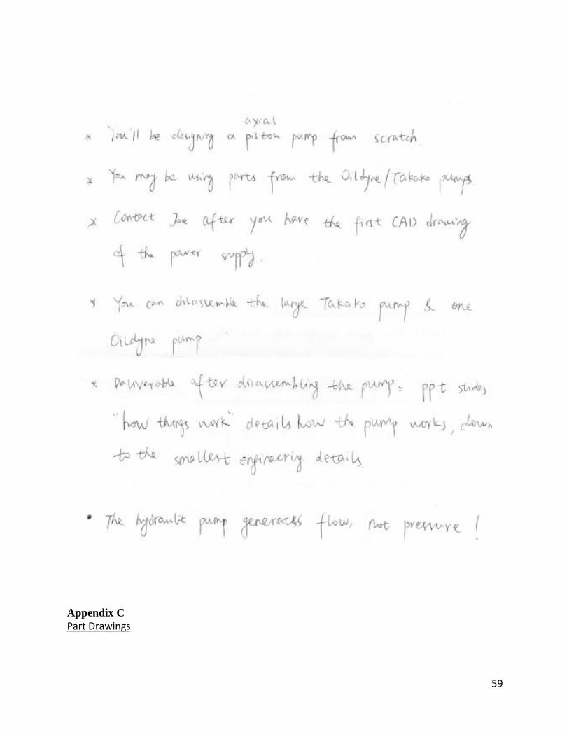
59
Appendix C
Part Drawings

.6070 .6570
R.0360
R.1050
.0273
144.7917°
.2120
.1680 .1250
6DO NOT SCALE DRAWING
001SHEET 1 OF 1
05/07/13
05/07/13KH
DP
UNLESS OTHERWISE SPECIFIED:
SCALE: 2:1 WEIGHT: 0.007 lbs
REVDWG. NO.
ASIZE
TITLE:
NAME DATE
COMMENTS:
Q.A.
MFG APPR.
ENG APPR.
CHECKED
DRAWN
FINISH
MATERIAL
INTERPRET GEOMETRICTOLERANCING PER:
DIMENSIONS ARE IN INCHESTOLERANCES:FRACTIONALANGULAR: MACH BEND TWO PLACE DECIMAL THREE PLACE DECIMAL
APPLICATION
USED ONNEXT ASSY
PROPRIETARY AND CONFIDENTIALTHE INFORMATION CONTAINED IN THISDRAWING IS THE SOLE PROPERTY OF<INSERT COMPANY NAME HERE>. ANY REPRODUCTION IN PART OR AS A WHOLEWITHOUT THE WRITTEN PERMISSION OF<INSERT COMPANY NAME HERE> IS PROHIBITED.
5 4 3 2 1
Piston4130 SteelSolidWorks Student Edition.
For Academic Use Only.

.0743
.2353
.0100
R.1060
.2720
.2020 .0250
.2400
.2050 .1320
Slipper
4DO NOT SCALE DRAWING
002SHEET 1 OF 1
05/07/13
05/07/13KH
DP
UNLESS OTHERWISE SPECIFIED:
SCALE: 5:1 WEIGHT: 0.002 lbs
REVDWG. NO.
ASIZE
TITLE:
NAME DATE
COMMENTS:
Q.A.
MFG APPR.
ENG APPR.
CHECKED
DRAWN
FINISH
MATERIAL
INTERPRET GEOMETRICTOLERANCING PER:
DIMENSIONS ARE IN INCHESTOLERANCES:FRACTIONALANGULAR: MACH BEND TWO PLACE DECIMAL THREE PLACE DECIMAL
APPLICATION
USED ONNEXT ASSY
PROPRIETARY AND CONFIDENTIALTHE INFORMATION CONTAINED IN THISDRAWING IS THE SOLE PROPERTY OF<INSERT COMPANY NAME HERE>. ANY REPRODUCTION IN PART OR AS A WHOLEWITHOUT THE WRITTEN PERMISSION OF<INSERT COMPANY NAME HERE> IS PROHIBITED.
5 4 3 2 1
4130 SteelSolidWorks Student Edition. For Academic Use Only.

.2120 R.1250
.0750 .9600
.3000
R.0650 72.0000°
.0141
45.0000°
R4.7500
.6900
.0400
.8380 .0258
R.2580
R.1940
.0800
R.0320
Cylinder Barrel
6DO NOT SCALE DRAWING
003SHEET 1 OF 1
05/07/13
05/07/13KH
DP
UNLESS OTHERWISE SPECIFIED:
SCALE: 2:1 WEIGHT: 0.124 lbs
REVDWG. NO.
ASIZE
TITLE:
NAME DATE
COMMENTS:
Q.A.
MFG APPR.
ENG APPR.
CHECKED
DRAWN
FINISH
MATERIAL
INTERPRET GEOMETRICTOLERANCING PER:
DIMENSIONS ARE IN INCHESTOLERANCES:FRACTIONALANGULAR: MACH BEND TWO PLACE DECIMAL THREE PLACE DECIMAL
APPLICATION
USED ONNEXT ASSY
PROPRIETARY AND CONFIDENTIALTHE INFORMATION CONTAINED IN THISDRAWING IS THE SOLE PROPERTY OF<INSERT COMPANY NAME HERE>. ANY REPRODUCTION IN PART OR AS A WHOLEWITHOUT THE WRITTEN PERMISSION OF<INSERT COMPANY NAME HERE> IS PROHIBITED.
5 4 3 2 1
4130 SteelSolidWorks Student Edition. For Academic Use Only.

.0692 .0692
.1600 .1600
.2500 R.4800
.4500 15.0000°
Swash Plate
2DO NOT SCALE DRAWING
004SHEET 1 OF 1
05/07/13
05/07/13KH
DP
UNLESS OTHERWISE SPECIFIED:
SCALE: 2:1 WEIGHT: 0.063 lbs
REVDWG. NO.
ASIZE
TITLE:
NAME DATE
COMMENTS:
Q.A.
MFG APPR.
ENG APPR.
CHECKED
DRAWN
FINISH
MATERIAL
INTERPRET GEOMETRICTOLERANCING PER:
DIMENSIONS ARE IN INCHESTOLERANCES:FRACTIONALANGULAR: MACH BEND TWO PLACE DECIMAL THREE PLACE DECIMAL
APPLICATION
USED ONNEXT ASSY
PROPRIETARY AND CONFIDENTIALTHE INFORMATION CONTAINED IN THISDRAWING IS THE SOLE PROPERTY OF<INSERT COMPANY NAME HERE>. ANY REPRODUCTION IN PART OR AS A WHOLEWITHOUT THE WRITTEN PERMISSION OF<INSERT COMPANY NAME HERE> IS PROHIBITED.
5 4 3 2 1
4130 SteelSolidWorks Student Edition. For Academic Use Only.

R4.7500
.0100 .1000
.2000
.9600 .8000
R.2580 R.1940
R.1940 R.2580
R.0320
.0451
R.3480 R.3030
R.1490 R.1040
.1600
.0558 .0450
R.0500
120.0000°
Valve Plate
6DO NOT SCALE DRAWING
005SHEET 1 OF 1
05/07/13
05/07/13KH
DP
UNLESS OTHERWISE SPECIFIED:
SCALE: 2:1 WEIGHT: 0.037 lbs
REVDWG. NO.
ASIZE
TITLE:
NAME DATE
COMMENTS:
Q.A.
MFG APPR.
ENG APPR.
CHECKED
DRAWN
FINISH
MATERIAL
INTERPRET GEOMETRICTOLERANCING PER:
DIMENSIONS ARE IN INCHESTOLERANCES:FRACTIONALANGULAR: MACH BEND TWO PLACE DECIMAL THREE PLACE DECIMAL
APPLICATION
USED ONNEXT ASSY
PROPRIETARY AND CONFIDENTIALTHE INFORMATION CONTAINED IN THISDRAWING IS THE SOLE PROPERTY OF<INSERT COMPANY NAME HERE>. ANY REPRODUCTION IN PART OR AS A WHOLEWITHOUT THE WRITTEN PERMISSION OF<INSERT COMPANY NAME HERE> IS PROHIBITED.
5 4 3 2 1
4130 SteelSolidWorks Student Edition. For Academic Use Only.

.787
.118 .010
Spring
4DO NOT SCALE DRAWING
006SHEET 1 OF 1
05/07/13KH
UNLESS OTHERWISE SPECIFIED:
SCALE: 4:1 WEIGHT: 0.001 lbs
REVDWG. NO.
ASIZE
TITLE:
NAME DATE
COMMENTS:
Q.A.
MFG APPR.
ENG APPR.
CHECKED
DRAWN
FINISH
MATERIAL
INTERPRET GEOMETRICTOLERANCING PER:
DIMENSIONS ARE IN INCHESTOLERANCES:FRACTIONALANGULAR: MACH BEND TWO PLACE DECIMAL THREE PLACE DECIMAL
APPLICATION
USED ONNEXT ASSY
PROPRIETARY AND CONFIDENTIALTHE INFORMATION CONTAINED IN THISDRAWING IS THE SOLE PROPERTY OF<INSERT COMPANY NAME HERE>. ANY REPRODUCTION IN PART OR AS A WHOLEWITHOUT THE WRITTEN PERMISSION OF<INSERT COMPANY NAME HERE> IS PROHIBITED.
5 4 3 2 1
Stainless SteelSolidWorks Student Edition. For Academic Use Only.

.070
1.316 1.176
O-Ring
0DO NOT SCALE DRAWING
007SHEET 1 OF 1
05/07/13KH
UNLESS OTHERWISE SPECIFIED:
SCALE: 2:1 WEIGHT: 0.001 lbs
REVDWG. NO.
ASIZE
TITLE:
NAME DATE
COMMENTS:
Q.A.
MFG APPR.
ENG APPR.
CHECKED
DRAWN
FINISH
MATERIAL
INTERPRET GEOMETRICTOLERANCING PER:
DIMENSIONS ARE IN INCHESTOLERANCES:FRACTIONALANGULAR: MACH BEND TWO PLACE DECIMAL THREE PLACE DECIMAL
APPLICATION
USED ONNEXT ASSY
PROPRIETARY AND CONFIDENTIALTHE INFORMATION CONTAINED IN THISDRAWING IS THE SOLE PROPERTY OF<INSERT COMPANY NAME HERE>. ANY REPRODUCTION IN PART OR AS A WHOLEWITHOUT THE WRITTEN PERMISSION OF<INSERT COMPANY NAME HERE> IS PROHIBITED.
5 4 3 2 1
Buna-NSolidWorks Student Edition. For Academic Use Only.

.094
.375 .250
Shaft Seal
0DO NOT SCALE DRAWING
008SHEET 1 OF 1
05/07/13KH
UNLESS OTHERWISE SPECIFIED:
SCALE: 6:1 WEIGHT: 0.001 lbs
REVDWG. NO.
ASIZE
TITLE:
NAME DATE
COMMENTS:
Q.A.
MFG APPR.
ENG APPR.
CHECKED
DRAWN
FINISH
MATERIAL
INTERPRET GEOMETRICTOLERANCING PER:
DIMENSIONS ARE IN INCHESTOLERANCES:FRACTIONALANGULAR: MACH BEND TWO PLACE DECIMAL THREE PLACE DECIMAL
APPLICATION
USED ONNEXT ASSY
PROPRIETARY AND CONFIDENTIALTHE INFORMATION CONTAINED IN THISDRAWING IS THE SOLE PROPERTY OF<INSERT COMPANY NAME HERE>. ANY REPRODUCTION IN PART OR AS A WHOLEWITHOUT THE WRITTEN PERMISSION OF<INSERT COMPANY NAME HERE> IS PROHIBITED.
5 4 3 2 1
PTFESolidWorks Student Edition. For Academic Use Only.

.438
.250
.700 .750
.163
1/4" - 20 x 3/4" UNC Thread
Manifold CoverBolt
0DO NOT SCALE DRAWING
009SHEET 1 OF 1
05/07/13KH
UNLESS OTHERWISE SPECIFIED:
SCALE: 2:1 WEIGHT: 0.006 lbs
REVDWG. NO.
ASIZE
TITLE:
NAME DATE
COMMENTS:
1/4" - 20 X 0.75" Aluminum Bolts
Q.A.
MFG APPR.
ENG APPR.
CHECKED
DRAWN
FINISH
MATERIAL
INTERPRET GEOMETRICTOLERANCING PER:
DIMENSIONS ARE IN INCHESTOLERANCES:FRACTIONALANGULAR: MACH BEND TWO PLACE DECIMAL THREE PLACE DECIMAL
APPLICATION
USED ONNEXT ASSY
PROPRIETARY AND CONFIDENTIALTHE INFORMATION CONTAINED IN THISDRAWING IS THE SOLE PROPERTY OF<INSERT COMPANY NAME HERE>. ANY REPRODUCTION IN PART OR AS A WHOLEWITHOUT THE WRITTEN PERMISSION OF<INSERT COMPANY NAME HERE> IS PROHIBITED.
5 4 3 2 1
AluminumSolidWorks Student Edition. For Academic Use Only.

5.3502
10
0.685
45.00°
7.140
M3 x 0.5 x 10 Thread
Gearhead Bolts
0DO NOT SCALE DRAWING
010SHEET 1 OF 1
05/07/13KH
UNLESS OTHERWISE SPECIFIED:
SCALE: 4:1 WEIGHT: 0.001 lbs
REVDWG. NO.
ASIZE
TITLE:
NAME DATE
COMMENTS:
M3 x 0.5 x 10mm Aluminum Flat Head Socket Screw
Q.A.
MFG APPR.
ENG APPR.
CHECKED
DRAWN
FINISH
MATERIAL
INTERPRET GEOMETRICTOLERANCING PER:
DIMENSIONS ARE IN MMTOLERANCES:FRACTIONALANGULAR: MACH BEND TWO PLACE DECIMAL THREE PLACE DECIMAL
APPLICATION
USED ONNEXT ASSY
PROPRIETARY AND CONFIDENTIALTHE INFORMATION CONTAINED IN THISDRAWING IS THE SOLE PROPERTY OF<INSERT COMPANY NAME HERE>. ANY REPRODUCTION IN PART OR AS A WHOLEWITHOUT THE WRITTEN PERMISSION OF<INSERT COMPANY NAME HERE> IS PROHIBITED.
5 4 3 2 1
AluminumSolidWorks Student Edition. For Academic Use Only.

2
5.350
0.685
8 45.00°
5.140
M3 x 0.5 x 8mm Thread
Attachment BracketScrews
0DO NOT SCALE DRAWING
011SHEET 1 OF 1
05/07/13KH
UNLESS OTHERWISE SPECIFIED:
SCALE: 6:1 WEIGHT: 0.001 lbs
REVDWG. NO.
ASIZE
TITLE:
NAME DATE
COMMENTS:
Q.A.
MFG APPR.
ENG APPR.
CHECKED
DRAWN
FINISH
MATERIAL
INTERPRET GEOMETRICTOLERANCING PER:
DIMENSIONS ARE IN MMTOLERANCES:FRACTIONALANGULAR: MACH BEND TWO PLACE DECIMAL THREE PLACE DECIMAL
APPLICATION
USED ONNEXT ASSY
PROPRIETARY AND CONFIDENTIALTHE INFORMATION CONTAINED IN THISDRAWING IS THE SOLE PROPERTY OF<INSERT COMPANY NAME HERE>. ANY REPRODUCTION IN PART OR AS A WHOLEWITHOUT THE WRITTEN PERMISSION OF<INSERT COMPANY NAME HERE> IS PROHIBITED.
5 4 3 2 1
AluminumSolidWorks Student Edition. For Academic Use Only.

1.875
R.250 3.250
R.250
R.759 1.250
R.500
1.500
.300
1.500
.875
.125
4.875
ManifoldAttachment
Bracket
0DO NOT SCALE DRAWING
012-1SHEET 1 OF 2
05/07/13KH
UNLESS OTHERWISE SPECIFIED:
SCALE: 2:3 WEIGHT: 0.044lbs
REVDWG. NO.
ASIZE
TITLE:
NAME DATE
COMMENTS:
Q.A.
MFG APPR.
ENG APPR.
CHECKED
DRAWN
PolypropyleneFINISH
MATERIAL
INTERPRET GEOMETRICTOLERANCING PER:
DIMENSIONS ARE IN INCHESTOLERANCES:FRACTIONALANGULAR: MACH BEND TWO PLACE DECIMAL THREE PLACE DECIMAL
APPLICATION
USED ONNEXT ASSY
PROPRIETARY AND CONFIDENTIALTHE INFORMATION CONTAINED IN THISDRAWING IS THE SOLE PROPERTY OF<INSERT COMPANY NAME HERE>. ANY REPRODUCTION IN PART OR AS A WHOLEWITHOUT THE WRITTEN PERMISSION OF<INSERT COMPANY NAME HERE> IS PROHIBITED.
5 4 3 2 1
SolidWorks Student Edition. For Academic Use Only.

4X .134 3.400 THRU ALL .265 6.720 X 90°
2X .225 THRU
.250
2.125
.250
.625
.690
ManifoldAttachment
Bracket0
DO NOT SCALE DRAWING
012-2SHEET 2 OF 2
05/07/13KH
UNLESS OTHERWISE SPECIFIED:
SCALE: 2:3 WEIGHT: 0.044 lbs
REVDWG. NO.
ASIZE
TITLE:
NAME DATE
COMMENTS:
Countersunk clearance holes are for M3 socket screws
Q.A.
MFG APPR.
ENG APPR.
CHECKED
DRAWN
PolypropyleneFINISH
MATERIAL
INTERPRET GEOMETRICTOLERANCING PER:
DIMENSIONS ARE IN INCHESTOLERANCES:FRACTIONALANGULAR: MACH BEND TWO PLACE DECIMAL THREE PLACE DECIMAL
APPLICATION
USED ONNEXT ASSY
PROPRIETARY AND CONFIDENTIALTHE INFORMATION CONTAINED IN THISDRAWING IS THE SOLE PROPERTY OF<INSERT COMPANY NAME HERE>. ANY REPRODUCTION IN PART OR AS A WHOLEWITHOUT THE WRITTEN PERMISSION OF<INSERT COMPANY NAME HERE> IS PROHIBITED.
5 4 3 2 1
SolidWorks Student Edition. For Academic Use Only.

0.832
1.0
69
0.3
75
0.375
0.0
60 1.8
75
1.0
00
1.082 4
.452
0.2
50
0.3
25
5.952
0.125
0.2
50 0.125
4.452
1.3
19 0
.300
1.500
Battery Case
0DO NOT SCALE DRAWING
013SHEET 1 OF 1
05/07/13
05/07/13KH
DP
UNLESS OTHERWISE SPECIFIED:
SCALE: 1:5 WEIGHT: 0.058 lbs
REVDWG. NO.
ASIZE
TITLE:
NAME DATE
COMMENTS:
Q.A.
MFG APPR.
ENG APPR.
CHECKED
DRAWN
PolypropyleneFINISH
MATERIAL
INTERPRET GEOMETRICTOLERANCING PER:
DIMENSIONS ARE IN INCHESTOLERANCES:FRACTIONALANGULAR: MACH BEND TWO PLACE DECIMAL THREE PLACE DECIMAL
APPLICATION
USED ONNEXT ASSY
PROPRIETARY AND CONFIDENTIALTHE INFORMATION CONTAINED IN THISDRAWING IS THE SOLE PROPERTY OF<INSERT COMPANY NAME HERE>. ANY REPRODUCTION IN PART OR AS A WHOLEWITHOUT THE WRITTEN PERMISSION OF<INSERT COMPANY NAME HERE> IS PROHIBITED.
5 4 3 2 1
SolidWorks Student Edition. For Academic Use Only.
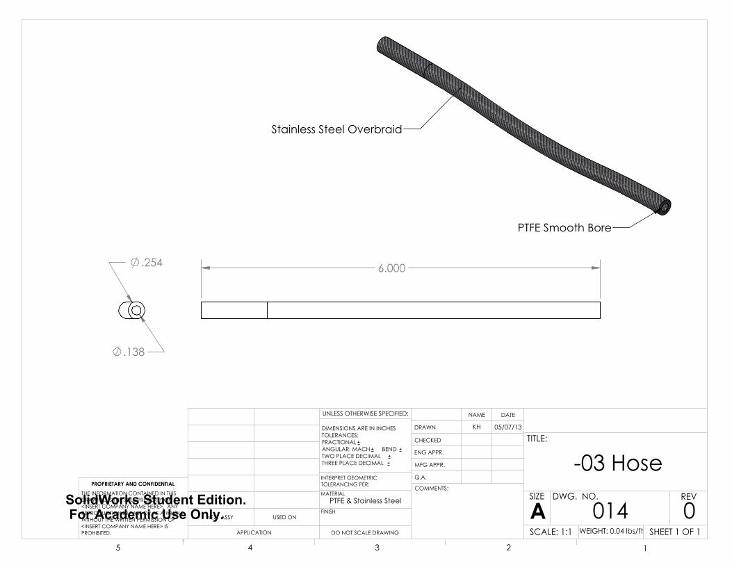
6.000
Stainless Steel Overbraid
PTFE Smooth Bore
.138
.254
-03 Hose
0DO NOT SCALE DRAWING
014SHEET 1 OF 1
05/07/13KH
UNLESS OTHERWISE SPECIFIED:
SCALE: 1:1 WEIGHT: 0.04 lbs/ft
REVDWG. NO.
ASIZE
TITLE:
NAME DATE
COMMENTS:
Q.A.
MFG APPR.
ENG APPR.
CHECKED
DRAWN
PTFE & Stainless SteelFINISH
MATERIAL
INTERPRET GEOMETRICTOLERANCING PER:
DIMENSIONS ARE IN INCHESTOLERANCES:FRACTIONALANGULAR: MACH BEND TWO PLACE DECIMAL THREE PLACE DECIMAL
APPLICATION
USED ONNEXT ASSY
PROPRIETARY AND CONFIDENTIALTHE INFORMATION CONTAINED IN THISDRAWING IS THE SOLE PROPERTY OF<INSERT COMPANY NAME HERE>. ANY REPRODUCTION IN PART OR AS A WHOLEWITHOUT THE WRITTEN PERMISSION OF<INSERT COMPANY NAME HERE> IS PROHIBITED.
5 4 3 2 1
SolidWorks Student Edition. For Academic Use Only.

37.00°
3/8-24 JIC/UNF Threads
Accepts AN -03 Hose
.125
.625
JIC Male StraightHose Fitting
0DO NOT SCALE DRAWING
015SHEET 1 OF 1
05/07/13KH
UNLESS OTHERWISE SPECIFIED:
SCALE: 2:1 WEIGHT: 0.022 lbs
REVDWG. NO.
ASIZE
TITLE:
NAME DATE
COMMENTS:
Goodridge JIC Male Stright Fitting for -03 Hose
Q.A.
MFG APPR.
ENG APPR.
CHECKED
DRAWN
AluminumFINISH
MATERIAL
INTERPRET GEOMETRICTOLERANCING PER:
DIMENSIONS ARE IN INCHESTOLERANCES:FRACTIONALANGULAR: MACH BEND TWO PLACE DECIMAL THREE PLACE DECIMAL
APPLICATION
USED ONNEXT ASSY
PROPRIETARY AND CONFIDENTIALTHE INFORMATION CONTAINED IN THISDRAWING IS THE SOLE PROPERTY OF<INSERT COMPANY NAME HERE>. ANY REPRODUCTION IN PART OR AS A WHOLEWITHOUT THE WRITTEN PERMISSION OF<INSERT COMPANY NAME HERE> IS PROHIBITED.
5 4 3 2 1
SolidWorks Student Edition. For Academic Use Only.

.250
3.500
1.260 .203
.748 .203.375 THRU
.375
.375
4X .257 THRU ALL
.375
CL
1.750
.047
R 0.1" Fillet on all Edges
Gearhead Mount
Manifold Cover
0DO NOT SCALE DRAWING
016-1SHEET 1 OF 2
05/07/13KH
UNLESS OTHERWISE SPECIFIED:
SCALE: 1:1 WEIGHT: 0.131 lbs
REVDWG. NO.
ASIZE
TITLE:
NAME DATE
COMMENTS:
Q.A.
MFG APPR.
ENG APPR.
CHECKED
DRAWN
AlSi10MgFINISH
MATERIAL
INTERPRET GEOMETRICTOLERANCING PER:
DIMENSIONS ARE IN INCHESTOLERANCES:FRACTIONALANGULAR: MACH BEND TWO PLACE DECIMAL THREE PLACE DECIMAL
APPLICATION
USED ONNEXT ASSY
PROPRIETARY AND CONFIDENTIALTHE INFORMATION CONTAINED IN THISDRAWING IS THE SOLE PROPERTY OF<INSERT COMPANY NAME HERE>. ANY REPRODUCTION IN PART OR AS A WHOLEWITHOUT THE WRITTEN PERMISSION OF<INSERT COMPANY NAME HERE> IS PROHIBITED.
5 4 3 2 1
SolidWorks Student Edition. For Academic Use Only.

4X .126 3.20 THRU ALL .265 6.72 X 90°
.265 6.72 .050 1.27 1.436 R.588
.362
.362
O-Ring Groove
Shaft HoleCL
Manifold Cover
0DO NOT SCALE DRAWING
016-2SHEET 2 OF 2
05/07/13KH
UNLESS OTHERWISE SPECIFIED:
SCALE: 1:1 WEIGHT: 0.131 lbs
REVDWG. NO.
ASIZE
TITLE:
NAME DATE
COMMENTS:
Q.A.
MFG APPR.
ENG APPR.
CHECKED
DRAWN
AlSi10MgFINISH
MATERIAL
INTERPRET GEOMETRICTOLERANCING PER:
DIMENSIONS ARE IN INCHESTOLERANCES:FRACTIONALANGULAR: MACH BEND TWO PLACE DECIMAL THREE PLACE DECIMAL
APPLICATION
USED ONNEXT ASSY
PROPRIETARY AND CONFIDENTIALTHE INFORMATION CONTAINED IN THISDRAWING IS THE SOLE PROPERTY OF<INSERT COMPANY NAME HERE>. ANY REPRODUCTION IN PART OR AS A WHOLEWITHOUT THE WRITTEN PERMISSION OF<INSERT COMPANY NAME HERE> IS PROHIBITED.
5 4 3 2 1
SolidWorks Student Edition. For Academic Use Only.

4X .0625 Breather Tube
3.5000
3.1250
CL
1.7500
.8750
.7500
Breather Tube7/8"-20 UNEF-3BThreadedSolenoidPort
2X .2250 Wire Hole
4X .0984 2.5000 .3000 7.6200 M3X0.5 - 6H .2400 6.0960
.5000
.3750
.7500
.8148
.8750
Manifold
7DO NOT SCALE DRAWING
017-1SHEET 1 OF 5
05/07/13KH
UNLESS OTHERWISE SPECIFIED:
SCALE: 1:2 WEIGHT: 1.486 lbs
REVDWG. NO.
ASIZE
TITLE:
NAME DATE
COMMENTS:
Q.A.
MFG APPR.
ENG APPR.
CHECKED
DRAWN
AlSi10MgFINISH
MATERIAL
INTERPRET GEOMETRICTOLERANCING PER:
DIMENSIONS ARE IN INCHESTOLERANCES:FRACTIONALANGULAR: MACH BEND TWO PLACE DECIMAL THREE PLACE DECIMAL
APPLICATION
USED ONNEXT ASSY
PROPRIETARY AND CONFIDENTIALTHE INFORMATION CONTAINED IN THISDRAWING IS THE SOLE PROPERTY OF<INSERT COMPANY NAME HERE>. ANY REPRODUCTION IN PART OR AS A WHOLEWITHOUT THE WRITTEN PERMISSION OF<INSERT COMPANY NAME HERE> IS PROHIBITED.
5 4 3 2 1
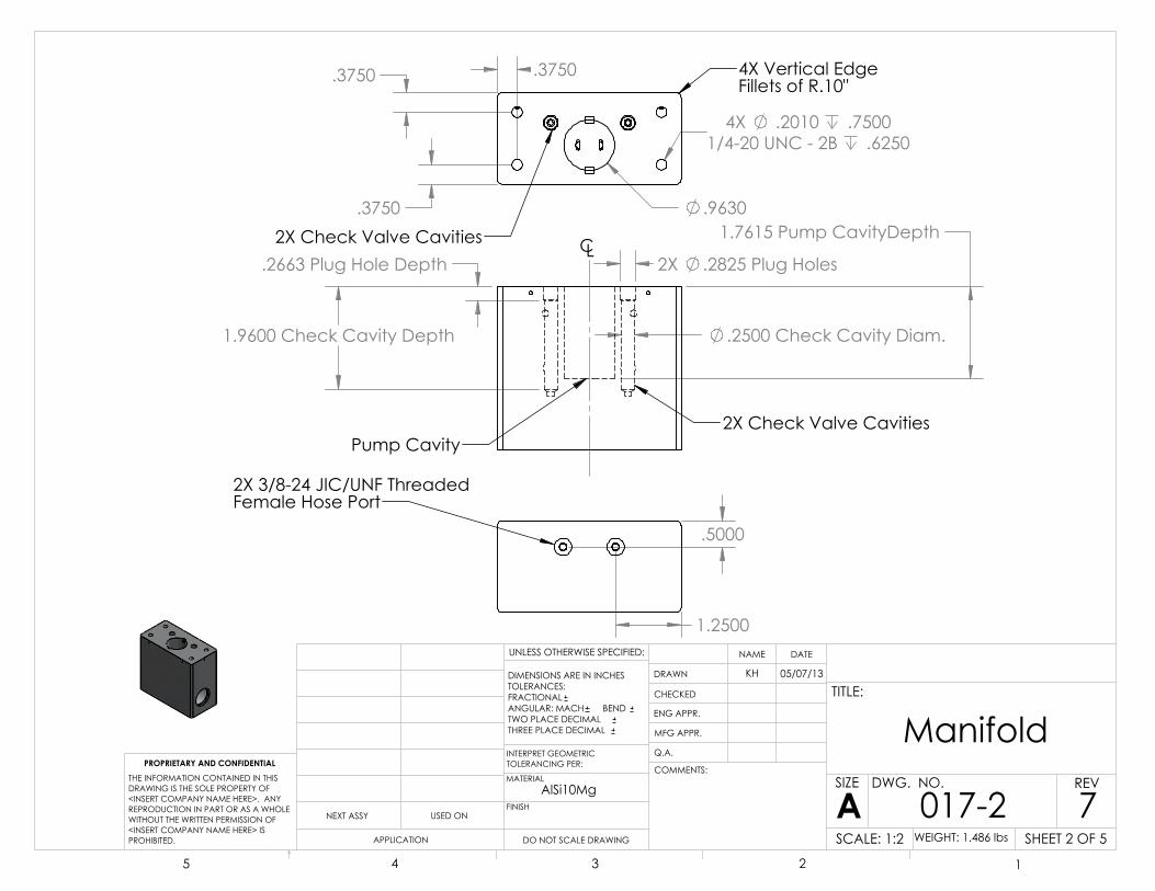
1.7615 Pump CavityDepth
1.9600 Check Cavity Depth
.2663 Plug Hole Depth 2X .2825 Plug Holes
.2500 Check Cavity Diam.
CL
Pump Cavity2X Check Valve Cavities
4X .2010 .75001/4-20 UNC - 2B .6250
.3750
.3750 .3750
.9630
4X Vertical EdgeFillets of R.10"
2X Check Valve Cavities
.5000
1.2500
2X 3/8-24 JIC/UNF ThreadedFemale Hose Port
Manifold
7DO NOT SCALE DRAWING
017-2SHEET 2 OF 5
05/07/13KH
UNLESS OTHERWISE SPECIFIED:
SCALE: 1:2 WEIGHT: 1.486 lbs
REVDWG. NO.
ASIZE
TITLE:
NAME DATE
COMMENTS:
Q.A.
MFG APPR.
ENG APPR.
CHECKED
DRAWN
AlSi10MgFINISH
MATERIAL
INTERPRET GEOMETRICTOLERANCING PER:
DIMENSIONS ARE IN INCHESTOLERANCES:FRACTIONALANGULAR: MACH BEND TWO PLACE DECIMAL THREE PLACE DECIMAL
APPLICATION
USED ONNEXT ASSY
PROPRIETARY AND CONFIDENTIALTHE INFORMATION CONTAINED IN THISDRAWING IS THE SOLE PROPERTY OF<INSERT COMPANY NAME HERE>. ANY REPRODUCTION IN PART OR AS A WHOLEWITHOUT THE WRITTEN PERMISSION OF<INSERT COMPANY NAME HERE> IS PROHIBITED.
5 4 3 2 1

Solenoid Cavity
Reservoir Check Cavity
Reservoir to Check Tube
Solenoid LocatingPin Cavity
1/16" Breather Tubes
Pump Cavity
1/8" Check toMain Tube
Female 3/8" JIC(Hose Connects Here)
1/8" Main Pump toActuator Tube
1/8" Pilot Line(Solenoid to Check)
Manifold
7DO NOT SCALE DRAWING
017-3SHEET 3 OF 5
05/07/13KH
UNLESS OTHERWISE SPECIFIED:
SCALE: 2:3 WEIGHT: 1.486 lbs
REVDWG. NO.
ASIZE
TITLE:
NAME DATE
COMMENTS:
Q.A.
MFG APPR.
ENG APPR.
CHECKED
DRAWN
AlSi10MgFINISH
MATERIAL
INTERPRET GEOMETRICTOLERANCING PER:
DIMENSIONS ARE IN INCHESTOLERANCES:FRACTIONALANGULAR: MACH BEND TWO PLACE DECIMAL THREE PLACE DECIMAL
APPLICATION
USED ONNEXT ASSY
PROPRIETARY AND CONFIDENTIALTHE INFORMATION CONTAINED IN THISDRAWING IS THE SOLE PROPERTY OF<INSERT COMPANY NAME HERE>. ANY REPRODUCTION IN PART OR AS A WHOLEWITHOUT THE WRITTEN PERMISSION OF<INSERT COMPANY NAME HERE> IS PROHIBITED.
5 4 3 2 1

D
D SECTION D-D SCALE 1 : 2
Pump Drain
Pump Cavity
1/8" Pilot Lines
Reservoir
J J
SECTION J-J SCALE 1 : 2
1/8" Check to Main Tube
Solenoid Cavity
1/8" Pilot Lines
1/8" Main Lines(Pump to Actuator)
Breather Tubes
Manifold
7DO NOT SCALE DRAWING
017-4SHEET 4 OF 5
05/07/13KH
UNLESS OTHERWISE SPECIFIED:
SCALE: 2:3 WEIGHT: 1.486 lbs
REVDWG. NO.
ASIZE
TITLE:
NAME DATE
COMMENTS:
Q.A.
MFG APPR.
ENG APPR.
CHECKED
DRAWN
AlSi10MgFINISH
MATERIAL
INTERPRET GEOMETRICTOLERANCING PER:
DIMENSIONS ARE IN INCHESTOLERANCES:FRACTIONALANGULAR: MACH BEND TWO PLACE DECIMAL THREE PLACE DECIMAL
APPLICATION
USED ONNEXT ASSY
PROPRIETARY AND CONFIDENTIALTHE INFORMATION CONTAINED IN THISDRAWING IS THE SOLE PROPERTY OF<INSERT COMPANY NAME HERE>. ANY REPRODUCTION IN PART OR AS A WHOLEWITHOUT THE WRITTEN PERMISSION OF<INSERT COMPANY NAME HERE> IS PROHIBITED.
5 4 3 2 1

Reservoir
Wire Hole
Check Valve Cavity
Pump Cavity
1/8" Pilot Line #21/8" Pilot Line #1
Manifold
7DO NOT SCALE DRAWING
017-5SHEET 5 OF 5
05/07/13KH
UNLESS OTHERWISE SPECIFIED:
SCALE: 2:3 WEIGHT: 1.486 lbs
REVDWG. NO.
ASIZE
TITLE:
NAME DATE
COMMENTS:
Q.A.
MFG APPR.
ENG APPR.
CHECKED
DRAWN
AlSi10MgFINISH
MATERIAL
INTERPRET GEOMETRICTOLERANCING PER:
DIMENSIONS ARE IN INCHESTOLERANCES:FRACTIONALANGULAR: MACH BEND TWO PLACE DECIMAL THREE PLACE DECIMAL
APPLICATION
USED ONNEXT ASSY
PROPRIETARY AND CONFIDENTIALTHE INFORMATION CONTAINED IN THISDRAWING IS THE SOLE PROPERTY OF<INSERT COMPANY NAME HERE>. ANY REPRODUCTION IN PART OR AS A WHOLEWITHOUT THE WRITTEN PERMISSION OF<INSERT COMPANY NAME HERE> IS PROHIBITED.
5 4 3 2 1

43
1.693
5.500.217
148
5.827
5.5mm Bullet
37
1.457
6 Cell3700 mAh Capacity
Battery
0DO NOT SCALE DRAWING
018SHEET 1 OF 1
05/07/13KH
UNLESS OTHERWISE SPECIFIED:
SCALE: 1:2 WEIGHT: 1.110 lbs
REVDWG. NO.
ASIZE
TITLE:
NAME DATE
COMMENTS:
Q.A.
MFG APPR.
ENG APPR.
CHECKED
DRAWN
FINISH
MATERIAL
INTERPRET GEOMETRICTOLERANCING PER:
DIMENSIONS ARE IN INCHESTOLERANCES:FRACTIONALANGULAR: MACH BEND TWO PLACE DECIMAL THREE PLACE DECIMAL
APPLICATION
USED ONNEXT ASSY
PROPRIETARY AND CONFIDENTIALTHE INFORMATION CONTAINED IN THISDRAWING IS THE SOLE PROPERTY OF<INSERT COMPANY NAME HERE>. ANY REPRODUCTION IN PART OR AS A WHOLEWITHOUT THE WRITTEN PERMISSION OF<INSERT COMPANY NAME HERE> IS PROHIBITED.
5 4 3 2 1

max
on
gea
r
237
RE 25, 10 W 77/79 81.1 91.0 91.0 97.7 97.7 104.4 104.4 104.4 111.1 111.1 111.1 111.1RE 25, 10 W 77/79 MR 272 92.1 102.0 102.0 108.7 108.7 115.4 115.4 115.4 122.1 122.1 122.1 122.1RE 25, 10 W 77/79 Enc 22 274 95.2 105.1 105.1 111.8 111.8 118.5 118.5 118.5 125.2 125.2 125.2 125.2RE 25, 10 W 77/79 HED_ 5540 276/278 101.9 111.8 111.8 118.5 118.5 125.2 125.2 125.2 131.9 131.9 131.9 131.9RE 25, 10 W 77/79 DCT 22 286 103.4 113.3 113.3 120.0 120.0 126.7 126.7 126.7 133.4 133.4 133.4 133.4RE 25, 20 W 78 69.6 79.5 79.5 86.2 86.2 92.9 92.9 92.9 99.6 99.6 99.6 99.6RE 25, 20 W 78 MR 272 80.6 90.5 90.5 97.2 97.2 103.9 103.9 103.9 110.6 110.6 110.6 110.6RE 25, 20 W 78 HED_ 5540 277/280 90.4 100.3 100.3 107.0 107.0 113.7 113.7 113.7 120.4 120.4 120.4 120.4RE 25, 20 W 78 DCT22 286 91.9 101.8 101.8 108.5 108.5 115.2 115.2 115.2 121.9 121.9 121.9 121.9RE 25, 20 W 78 AB 28 330 103.7 113.6 113.6 120.3 120.3 127.0 127.0 127.0 133.7 133.7 133.7 133.7RE 25, 20 W 78 HED_ 5540 / AB 28 277/330 120.9 130.8 130.8 137.5 137.5 144.2 144.2 144.2 150.9 150.9 150.9 150.9RE 25, 20 W 79 AB 28 330 115.2 125.1 125.1 131.8 131.8 138.5 138.5 138.5 145.2 145.2 145.2 145.2RE 25, 20 W 79 HED_5540 / AB 28 330 132.4 142.3 142.3 149.0 149.0 155.7 155.7 155.7 162.4 162.4 162.4 162.4RE 30, 60 W 80 94.6 104.5 104.5 111.2 111.2 117.9 117.9 117.9 124.6 124.6 124.6 124.6RE 30, 60 W 80 MR 273 106.0 115.9 115.9 122.6 122.6 129.3 129.3 129.3 136.0 136.0 136.0 136.0RE 35, 90 W 81 97.6 107.5 107.5 114.2 114.2 120.9 120.9 120.9 127.6 127.6 127.6 127.6RE 35, 90 W 81 MR 273 109.0 118.9 118.9 125.6 125.6 132.3 132.3 132.3 139.0 139.0 139.0 139.0RE 35, 90 W 81 HED_ 5540 276/278 118.3 128.2 128.2 134.9 134.9 141.6 141.6 141.6 148.3 148.3 148.3 148.3RE 35, 90 W 81 DCT 22 287 115.7 125.6 125.6 132.3 132.3 139.0 139.0 139.0 145.7 145.7 145.7 145.7RE 35, 90 W 81 AB 28 330 133.7 143.6 143.6 150.3 150.3 157.0 157.0 157.0 163.7 163.7 163.7 163.7RE 35, 90 W 81 HEDS 5540 / AB 28 276/330 150.9 160.8 160.8 167.5 167.5 174.2 174.2 174.2 180.9 180.9 180.9 180.9A-max 26 101-108 71.3 81.2 81.2 87.9 87.9 94.6 94.6 94.6 101.3 101.3 101.3 101.3A-max 26 102-108 MEnc 13 285 78.4 88.3 88.3 95.0 95.0 101.7 101.7 101.7 108.4 108.4 108.4 108.4A-max 26 102-108 MR 272 80.1 90.0 90.0 96.7 96.7 103.4 103.4 103.4 110.1 110.1 110.1 110.1A-max 26 102-108 Enc 22 275 85.7 95.6 95.6 102.3 102.3 109.0 109.0 109.0 115.7 115.7 115.7 115.7A-max 26 102-108 HED_ 5540 277/278 89.7 99.6 99.6 106.3 106.3 113.0 113.0 113.0 119.7 119.7 119.7 119.7A-max 32 109/111 89.5 99.4 99.4 106.1 106.1 112.8 112.8 112.8 119.5 119.5 119.5 119.5A-max 32 110/112 88.1 98.0 98.0 104.7 104.7 111.4 111.4 111.4 118.1 118.1 118.1 118.1A-max 32 110/112 MR 273 99.3 109.2 109.2 115.9 115.9 122.6 122.6 122.6 129.3 129.3 129.3 129.3A-max 32 110/112 HED_ 5540 277/278 108.9 118.8 118.8 125.5 125.5 132.2 132.2 132.2 138.9 138.9 138.9 138.9
166930 166933 166938 166939 166944 166949 166954 166959 166962 166967 166972 166977
3.7 : 1 14 : 1 33 : 1 51 : 1 111 : 1 246 : 1 492 : 1 762 : 1 1181 : 1 1972 : 1 2829 : 1 4380 : 126/7
676/49529/16
17576/34313824/125
421824/171586112/175
19044/2510123776/8575
8626176/4375495144/175
109503/25
6 6 3 6 4 4 3 3 4 4 3 3166931 166934 166940 166945 166950 166955 166960 166963 166968 166973 1669784.8 : 1 18 : 1 66 : 1 123 : 1 295 : 1 531 : 1 913 : 1 1414 : 1 2189 : 1 3052 : 1 5247 : 1
24/5624/35
16224/2456877/56
101062/343331776/625
36501/402425488/1715
536406/2451907712/625
839523/160
4 4 4 3 3 4 3 3 3 3 3166932 166935 166941 166946 166951 166956 166961 166964 166969 166974 1669795.8 : 1 21 : 1 79 : 1 132 : 1 318 : 1 589 : 1 1093 : 1 1526 : 1 2362 : 1 3389 : 1 6285 : 1
23/4 299/143887/49
3312/25389376/1225
20631/35279841/256
9345024/61252066688/875
474513/1406436343/1024
3 3 3 3 4 3 3 4 3 3 3166936 166942 166947 166952 166957 166965 166970 16697523 : 1 86 : 1 159 : 1 411 : 1 636 : 1 1694 : 1 2548 : 1 3656 : 1576/25
14976/1751587/10
359424/87579488/125
1162213/6867962624/3125
457056/125
4 4 3 4 3 3 4 3166937 166943 166948 166953 166958 166966 166971 16697628 : 1 103 : 1 190 : 1 456 : 1 706 : 1 1828 : 1 2623 : 1 4060 : 1
138/53588/35
12167/6489401/196
158171/2242238912/1225
2056223/7843637933/896
3 3 3 3 3 3 3 31 2 2 3 3 4 4 4 5 5 5 51 3 3 6 6 6 6 6 6 6 6 6
1.25 3.75 3.75 7.5 7.5 7.5 7.5 7.5 7.5 7.5 7.5 7.580 75 75 70 70 60 60 60 50 50 50 50118 162 162 194 194 226 226 226 258 258 258 2580.7 0.8 0.8 1.0 1.0 1.0 1.0 1.0 1.0 1.0 1.0 1.01.5 0.8 0.8 0.7 0.7 0.7 0.7 0.7 0.7 0.7 0.7 0.7
26.5 36.4 36.4 43.1 43.1 49.8 49.8 49.8 56.5 56.5 56.5 56.5
M 1:2
May 2012 edition / subject to change maxon gear
Stock programStandard programSpecial program (on request)
maxon Modular System+ Motor Page + Sensor/Brake Page Overall length [mm] = Motor length + gearhead length + (sensor/brake) + assembly parts
overall length overall length
Technical DataPlanetary Gearhead straight teethOutput shaft stainless steel Shaft diameter as option 8 mmBearing at output ball bearingRadial play, 5 mm from flange max. 0.14 mmAxial play max. 0.4 mmMax. permissible axial load 120 NMax. permissible force for press fits 120 NSense of rotation, drive to output =Recommended input speed < 8000 rpmRecommended temperature range -40…+100°CNumber of stages 1 2 3 4 5Max. radial load, 10 mm from flange 140 N 140 N 140 N 140 N 140 N
Option: Low-noise version
Planetary Gearhead GP 32 C ∅32 mm, 1.0–6.0 NmCeramic Version
Article Numbers
Gearhead Data 1 Reduction 2 Reduction absolute 3 Max. motor shaft diameter mm
Article Numbers 1 Reduction 2 Reduction absolute 3 Max. motor shaft diameter mm
Article Numbers 1 Reduction 2 Reduction absolute 3 Max. motor shaft diameter mm
Article Numbers 1 Reduction 2 Reduction absolute 3 Max. motor shaft diameter mm
Article Numbers 1 Reduction 2 Reduction absolute 3 Max. motor shaft diameter mm 4 Number of stages 5 Max. continuous torque Nm 6 Intermittently permissible torque at gear output Nm 7 Max. efficiency % 8 Weight g 9 Average backlash no load ° 10 Mass inertia gcm2
11 Gearhead length L1 mm
1207_Gear.indd 237 15.05.2012 16:10:26

max
on
gea
r
238
RE-max 29 131-134 71.3 81.2 81.2 87.9 87.9 94.6 94.6 94.6 101.3 101.3 101.3 101.3RE-max 29 132/134 MR 272 80.1 90.0 90.0 96.7 96.7 103.4 103.4 103.4 110.1 110.1 110.1 110.1EC 32, 80 W 156 86.6 96.5 96.5 103.2 103.2 109.9 109.9 109.9 116.6 116.6 116.6 116.6EC 32, 80 W 156 HED_ 5540 277/279 105.0 114.9 114.9 121.6 121.6 128.3 128.3 128.3 135.0 135.0 135.0 135.0EC 32, 80 W 156 Res 26 287 106.7 116.6 116.6 123.3 123.3 130.0 130.0 130.0 136.7 136.7 136.7 136.7EC-max 22, 25 W 167 75.1 85.0 85.0 91.7 91.7 98.4 98.4 98.4 105.1 105.1 105.1 105.1EC-max 22, 25 W 167 MR 271 84.8 94.7 94.7 101.4 101.4 108.1 108.1 108.1 114.8 114.8 114.8 114.8EC-max 22, 25 W 167 AB 20 328 111.6 121.5 121.5 128.2 128.2 134.9 134.9 134.9 141.6 141.6 141.6 141.6EC-max 30, 40 W 168 68.9 78.8 78.8 85.5 85.5 92.2 92.2 92.2 98.9 98.9 98.9 98.9EC-max 30, 40 W 168 MR 272 81.1 91.0 91.0 97.7 97.7 104.4 104.4 104.4 111.1 111.1 111.1 111.1EC-max 30, 40 W 168 HEDL 5540 279 89.5 99.4 99.4 106.1 106.1 112.8 112.8 112.8 119.5 119.5 119.5 119.5EC-max 30, 40 W 168 AB 20 328 104.5 114.4 114.4 121.1 121.1 127.8 127.8 127.8 134.5 134.5 134.5 134.5EC-max 30, 40 W 168 HEDL 5540 / AB 20 279/328 125.1 135.0 135.0 141.7 141.7 148.4 148.4 148.4 155.1 155.1 155.1 155.1EC-4pole 22, 90 W 175 75.2 85.1 85.1 91.8 91.8 98.5 98.5 98.5 105.2 105.2 105.2 105.2EC-4pole 22, 90 W 175 HEDL 5540 280 96.7 106.6 106.6 113.3 113.3 120.0 120.0 120.0 126.7 126.7 126.7 126.7EC-4pole 22, 120 W 176 92.6 102.5 102.5 109.2 109.2 115.9 115.9 115.9 122.6 122.6 122.6 122.6EC-4pole 22, 120 W 176 HEDL 5540 280 114.1 124.0 124.0 130.7 130.7 137.4 137.4 137.4 144.1 144.1 144.1 144.1EC 32 flat, 15 W 188 44.5 54.4 54.4 61.1 61.1 67.8 67.8 67.8 74.5 74.5 74.5 74.5EC 32 flat IE, IP 00 189 54.6 64.5 64.5 71.2 71.2 77.9 77.9 77.9 84.6 84.6 84.6 84.6EC 32 flat IE, IP 40 189 56.3 66.2 66.2 72.9 72.9 79.6 79.6 79.6 86.3 86.3 86.3 86.3EC-i 40, 50 W 190 58.1 68.0 68.0 74.7 74.7 81.4 81.4 81.4 88.1 88.1 88.1 88.1EC-i 40, 50 W 190 MR 273 73.8 83.7 83.7 90.4 90.4 97.1 97.1 97.1 103.8 103.8 103.8 103.8EC-i 40, 50 W 190 HEDL 5540 280 81.5 91.4 91.4 98.1 98.1 104.8 104.8 104.8 111.5 111.5 111.5 111.5EC-i 40, 70 W 191 68.1 78.0 78.0 84.7 84.7 91.4 91.4 91.4 98.1 98.1 98.1 98.1EC-i 40, 70 W 191 MR 273 83.8 93.7 93.7 100.4 100.4 107.1 107.1 107.1 113.8 113.8 113.8 113.8EC-i 40, 70 W 191 HEDL 5540 280 91.5 101.4 101.4 108.1 108.1 114.8 114.8 114.8 121.5 121.5 121.5 121.5MCD EPOS, 60 W 325 150.2 160.1 160.1 166.8 166.8 173.5 173.5 173.5 180.2 180.2 180.2 180.2MCD EPOS P, 60 W 325 150.2 160.1 160.1 166.8 166.8 173.5 173.5 173.5 180.2 180.2 180.2 180.2
166930 166933 166938 166939 166944 166949 166954 166959 166962 166967 166972 166977
3.7 : 1 14 : 1 33 : 1 51 : 1 111 : 1 246 : 1 492 : 1 762 : 1 1181 : 1 1972 : 1 2829 : 1 4380 : 126/7 676/49
529/1617576/343
13824/125421824/1715
86112/17519044/25
10123776/85758626176/4375
495144/175109503/25
6 6 3 6 4 4 3 3 4 4 3 3166931 166934 166940 166945 166950 166955 166960 166963 166968 166973 1669784.8 : 1 18 : 1 66 : 1 123 : 1 295 : 1 531 : 1 913 : 1 1414 : 1 2189 : 1 3052 : 1 5247 : 1
24/5624/35
16224/2456877/56
101062/343331776/625
36501/402425488/1715
536406/2451907712/625
839523/160
4 4 4 3 3 4 3 3 3 3 3166932 166935 166941 166946 166951 166956 166961 166964 166969 166974 1669795.8 : 1 21 : 1 79 : 1 132 : 1 318 : 1 589 : 1 1093 : 1 1526 : 1 2362 : 1 3389 : 1 6285 : 1
23/4 299/143887/49
3312/25389376/1225
20631/35279841/256
9345024/61252066688/875
474513/1406436343/1024
3 3 3 3 4 3 3 4 3 3 3166936 166942 166947 166952 166957 166965 166970 16697523 : 1 86 : 1 159 : 1 411 : 1 636 : 1 1694 : 1 2548 : 1 3656 : 1576/25
14976/1751587/10
359424/87579488/125
1162213/6867962624/3125
457056/125
4 4 3 4 3 3 4 3166937 166943 166948 166953 166958 166966 166971 16697628 : 1 103 : 1 190 : 1 456 : 1 706 : 1 1828 : 1 2623 : 1 4060 : 1
138/53588/35
12167/6489401/196
158171/2242238912/1225
2056223/7843637933/896
3 3 3 3 3 3 3 31 2 2 3 3 4 4 4 5 5 5 51 3 3 6 6 6 6 6 6 6 6 6
1.25 3.75 3.75 7.5 7.5 7.5 7.5 7.5 7.5 7.5 7.5 7.580 75 75 70 70 60 60 60 50 50 50 50118 162 162 194 194 226 226 226 258 258 258 2580.7 0.8 0.8 1.0 1.0 1.0 1.0 1.0 1.0 1.0 1.0 1.01.5 0.8 0.8 0.7 0.7 0.7 0.7 0.7 0.7 0.7 0.7 0.7
26.5 36.4 36.4 43.1 43.1 49.8 49.8 49.8 56.5 56.5 56.5 56.5
M 1:2
maxon gear May 2012 edition / subject to change
Stock programStandard programSpecial program (on request)
maxon Modular System+ Motor Page + Sensor/Brake Page Overall length [mm] = Motor length + gearhead length + (sensor/brake) + assembly parts
overall length overall length
Technical DataPlanetary Gearhead straight teethOutput shaft stainless steel Shaft diameter as option 8 mmBearing at output ball bearingRadial play, 5 mm from flange max. 0.14 mmAxial play max. 0.4 mmMax. permissible axial load 120 NMax. permissible force for press fits 120 NSense of rotation, drive to output =Recommended input speed < 8000 rpmRecommended temperature range -40…+100°CNumber of stages 1 2 3 4 5Max. radial load, 10 mm from flange 140 N 140 N 140 N 140 N 140 N
Option: Low-noise version
Planetary Gearhead GP 32 C ∅32 mm, 1.0–6.0 NmCeramic Version
Article Numbers
Gearhead Data 1 Reduction 2 Reduction absolute 3 Max. motor shaft diameter mm
Article Numbers 1 Reduction 2 Reduction absolute 3 Max. motor shaft diameter mm
Article Numbers 1 Reduction 2 Reduction absolute 3 Max. motor shaft diameter mm
Article Numbers 1 Reduction 2 Reduction absolute 3 Max. motor shaft diameter mm
Article Numbers 1 Reduction 2 Reduction absolute 3 Max. motor shaft diameter mm 4 Number of stages 5 Max. continuous torque Nm 6 Intermittently permissible torque at gear output Nm 7 Max. efficiency % 8 Weight g 9 Average backlash no load ° 10 Mass inertia gcm2
11 Gearhead length L1 mm

197197
max
on
EC
mo
tor
197
max
on
flat
mo
tor
24 30 36 486110 6230 6330 3440234 194 166 48.1
4860 4990 5080 2540128 112 108 1343.21 2.36 1.93 0.9351150 1040 1000 87939.5 25.8 20.7 6.9785 84 83 84
0.608 1.16 1.74 6.890.463 0.691 0.966 5.8536.9 45.1 53.3 131259 212 179 72.74.26 5.44 5.85 3.828.07 10.3 11.1 7.24181 181 181 181
M 1:2
397172
70 W
25 50 75 125 150
1.0 2.0 3.0 4.0
397172 402685 402686 402687
May 2012 edition / subject to change maxon EC motor
Stock programStandard programSpecial program (on request)
Article Numbers
Specifications Operating Range Comments
n [rpm] Continuous operationIn observation of above listed thermal resistance (lines 17 and 18) the maximum permissible winding temperature will be reached during continuous operation at 25°C ambient.= Thermal limit.
Short term operationThe motor may be briefly overloaded (recurring).
Assigned power rating
maxon Modular System Overview on page 16 - 21
EC 45 flat ∅42.8 mm, brushless, 70 Watt
Motor Data (provisional)
Values at nominal voltage1 Nominal voltage V2 No load speed rpm3 No load current mA4 Nominal speed rpm5 Nominal torque (max. continuous torque) mNm6 Nominal current (max. continuous current) A7 Stall torque mNm8 Starting current A9 Max. efficiency %
Characteristics10 Terminal resistance phase to phase W11 Terminal inductance phase to phase mH12 Torque constant mNm / A13 Speed constant rpm / V14 Speed / torque gradient rpm / mNm15 Mechanical time constant ms16 Rotor inertia gcm2
Thermal data 17 Thermal resistance housing-ambient 3.25 K/W18 Thermal resistance winding-housing 4.22 K/W19 Thermal time constant winding 30.4 s20 Thermal time constant motor 162 s21 Ambient temperature -40 ... +100°C22 Max. permissible winding temperature +125°C
Mechanical data (preloaded ball bearings)23 Max. permissible speed 10000 rpm24 Axial play at axial load < 4.0 N 0 mm
> 4.0 N 0.14 mm25 Radial play preloaded26 Max. axial load (dynamic) 3.8 N27 Max. force for press fits (static) 50 N
(static, shaft supported) 1000 N28 Max. radial loading, 7.5 mm from flange 21 N
Other specifications29 Number of pole pairs 830 Number of phases 331 Weight of motor 141 g
Values listed in the table are nominal.
Connection Pin 1 Hall sensor 1* Pin 2 Hall sensor 2* Pin 3 VHall 4.5 ... 18 VDC Pin 4 Motor winding 3 Pin 5 Hall sensor 3* Pin 6 GND Pin 7 Motor winding 1 Pin 8 Motor winding 2 *Internal pull-up (7 … 13 kW) on pin 3 Wiring diagram for Hall sensors see p. 29
Cable Connection cable Universal, L = 500 mm 339380 Connection cable to EPOS, L = 500 mm 354045
Recommended Electronics:ESCON 50/5 Page 292DECS 50/5 297DEC 24/3 298DEC Module 50/5 299EPOS2 Module 36/2 312EPOS2 24/2 312EPOS2 24/5 313EPOS2 P 24/5 316EPOS3 70/10 EtherCAT 319Notes 20
with Hall sensors
Planetary Gearhead∅42 mm3 - 15 NmPage 243Spur Gearhead∅45 mm0.5 - 2.0 NmPage 244
Connector: 39-28-1083 Molex
OptionWith Cable and Connector (Ambient temperature -20 ... +100°C)
1206_EC_motor.indd 197 08.05.2012 13:26:24


/
GO
O~
~
OIH
O
0033'1
tUt-<0
S3'1\
s H
3'J
Go.
r fl
J
>z4{
~
~~
C
.,)I-U
I~J:
UI~
9 .Ji
w
t-1-
UI"'
~W
xW
I->
t-
~~Jog -J--0Il.ZW
W...
IUO
-JVI
-
-0 -0
"' a-
I I
on In
0 0
I I"'
"'N
N
... ...
.--W
iIII..
~
I"
-
i" III=
:
Ili ~
!1!1
i. ~
~
ill ~
~.~V
(OO
~
~i...w~~
0~...0-o9oV
) .,~
!iI.1

1
2
3
4
6
5
7
8
9
10
11
12
13
14
15
16
17
25
19
20
21
22
23
24
18
ITEM NO. PART NUMBER DESCRIPTION QTY.
1 Piston Custom Machined 52 Slipper Custom Machined 53 Cylinder Barrel Custom Machined 14 Swash Plate Custom Machined 15 Valve Plate Custom Machined 16 Spring Lee Spring 5
7 O-Ring Buna-N O-Rings - Dash #025 1
8 Shaft SealSpring-Loaded PTFE Shaft Seals - 1/4" Shaft Size, 3/8"
OD1
9 Manifold Cover Bolts 1/4" - 20 x 3/4" 4
10 Gearhead Bolts M3x.5x10mm Flat Head Socket Screw 4
11 Manifold Bracket Screws M3x.5x8mm Flat Head Socket Screw 4
12 Manifold Bracket Custom Made 113 Battery Case Custom Made 114 Hose -03 Hose 215 JIC Male Straight Fitting -03 Male JIC Fitting 216 Manifold Cover 3D Printed Aluminum 117 Manifold 3D Printed Aluminum 1
18 Battery 3700mAh Zippy Compact 1
19 DC Motor Maxon Motor 120 Lee PO Check Valve 0.250" 221 Check Pin For PO Check Valve 222 Aluminum Plug 0.281" Aluminum Plug 2
23 Aluminum Pin For 0.281" Aluminum Plug 2
24 Solenoid Valve2-Way Single Coil High Flow Piloting Solenoid
Valve2
25 Gear Head 3.7:1 Maxon Gearhead 1
ExplodedAssembly
0DO NOT SCALE DRAWING
100SHEET 1 OF 1
05/07/13KH
UNLESS OTHERWISE SPECIFIED:
SCALE: 1:4 WEIGHT: 4.032 lbs
REVDWG. NO.
ASIZE
TITLE:
NAME DATE
COMMENTS:
Q.A.
MFG APPR.
ENG APPR.
CHECKED
DRAWN
FINISH
MATERIAL
INTERPRET GEOMETRICTOLERANCING PER:
DIMENSIONS ARE IN INCHESTOLERANCES:FRACTIONALANGULAR: MACH BEND TWO PLACE DECIMAL THREE PLACE DECIMAL
APPLICATION
USED ONNEXT ASSY
PROPRIETARY AND CONFIDENTIALTHE INFORMATION CONTAINED IN THISDRAWING IS THE SOLE PROPERTY OF<INSERT COMPANY NAME HERE>. ANY REPRODUCTION IN PART OR AS A WHOLEWITHOUT THE WRITTEN PERMISSION OF<INSERT COMPANY NAME HERE> IS PROHIBITED.
5 4 3 2 1