
A-T Katalog 2011-04-07 / Boiler Blow down Valves ... Babcock – Leistungszentrum, Oberhausen ......
103
A-T ARMATUREN-TECHNIK GMBH Absperr-Armaturen, Regelventile, Turbinen-Umleitsysteme für Kraftwerkstechnik, Dampfanlagen und die Verfahrenstechnik, Öl- und Gas Pipelines Isolating, Control Valves and Turbine Bypass Systems for the Electric Power Industry, Steam Plant Utilities and Process Industry, oil and gas pipelines ® ARMATUREN-TECHNIK GMBH Choke Valves / Adjustable Choke Valves Ablaufregelventile / Boiler Blow down Valves Speisewasserregelventile / Boiler Feed water control Valves Kombinierte Sicherheits-Überströmstationen / Cobined safety and overflow Valves systems Speisewasserregelventile / Condensate Control Valves Reparatur und Instandhaltung kompletter Systeme / Maintenance and repair overhaul of complete systems Absperrschieber / Flexible Wedge Gate Valves Vorwärmerabsicherungen / Pre Heater Change over systems Dampf-Reduzier- und Umformventile / Pressure letdown Control Valves Mindestmengen-Anlagen / Pump re-circulations systems Einspritzwasserregelventile / Spray water Valves Rückschlagkappen / Swing check Valves Turbinen-Umleitstationen / Turbine Bypass Systems A-T Armaturen-Technik GmbH Babcock T-Bldg Tel.: +49 208 833 1700 E-Mail: [email protected] Duisburger Straße 375 46049 Oberhausen / Germany Fax: +49 208 833 1755 Web: www.at-armaturen.com ®
Transcript of A-T Katalog 2011-04-07 / Boiler Blow down Valves ... Babcock – Leistungszentrum, Oberhausen ......

A-T ARMATUREN-TECHNIK GMBH Absperr-Armaturen, Regelventile, Turbinen-Umleitsysteme für Kraftwerkstechnik, Dampfanlagen und die Verfahrenstechnik, Öl- und Gas Pipelines
Isolating, Control Valves and Turbine Bypass Systems for the Electric Power Industry, Steam Plant Utilities and Process Industry, oil and gas pipelines
®
ARMATUREN-TECHNIK GMBH
Choke Valves / Adjustable Choke Valves Ablaufregelventile / Boiler Blow down Valves
Speisewasserregelventile / Boiler Feed water control Valves Kombinierte Sicherheits-Überströmstationen / Cobined safety and overflow Valves systems
Speisewasserregelventile / Condensate Control Valves Reparatur und Instandhaltung kompletter Systeme /
Maintenance and repair overhaul of complete systems Absperrschieber / Flexible Wedge Gate Valves
Vorwärmerabsicherungen / Pre Heater Change over systems Dampf-Reduzier- und Umformventile / Pressure letdown Control Valves
Mindestmengen-Anlagen / Pump re-circulations systems Einspritzwasserregelventile / Spray water Valves
Rückschlagkappen / Swing check Valves Turbinen-Umleitstationen / Turbine Bypass Systems
A-T Armaturen-Technik GmbH Babcock T-Bldg Tel.: +49 208 833 1700 E-Mail: [email protected] Duisburger Straße 375 46049 Oberhausen / Germany Fax: +49 208 833 1755 Web: www.at-armaturen.com
®

A-T ARMATUREN-TECHNIK GMBH Absperr-Armaturen, Regelventile, Turbinen-Umleitsysteme für Kraftwerkstechnik, Dampfanlagen und die Verfahrenstechnik, Öl- und Gas Pipelines
Isolating, Control Valves and Turbine Bypass Systems for the Electric Power Industry, Steam Plant Utilities and Process Industry, oil and gas pipelines
®
UNTERNEHMENSPROFIL COMPANY PROFILE
®

A-T ARMATUREN-TECHNIK GMBH Absperr-Armaturen, Regelventile, Turbinen-Umleitsysteme für Kraftwerkstechnik, Dampfanlagen und die Verfahrenstechnik, Öl- und Gas Pipelines
Isolating, Control Valves and Turbine Bypass Systems for the Electric Power Industry, Steam Plant Utilities and Process Industry, oil and gas pipelines
3
®
INHALT
1. Vorstellung und Hintergrund 2. Entwurf und Konstruktion 3. Zertifikate und Genehmigungen 4. Fertigung 5. Produkte 6. Wichtige Referenzen 7. Vertriebs- und Service-Organisation
CONTENT
1. Introduction and History 2. Engineering and Production 3. Certificates and Approvals 4. Manufacturing facilities 5. Products 6. Main References 7. Sales and Service Organisation

A-T ARMATUREN-TECHNIK GMBH Absperr-Armaturen, Regelventile, Turbinen-Umleitsysteme für Kraftwerkstechnik, Dampfanlagen und die Verfahrenstechnik, Öl- und Gas Pipelines
Isolating, Control Valves and Turbine Bypass Systems for the Electric Power Industry, Steam Plant Utilities and Process Industry, oil and gas pipelines
4
®
Vorstellung und Hintergrund A – T Armaturen-Technik GmbH stellt sich vor als Hersteller von Hochdruckarmaturen. Zum Einsatz kommen unsere Absperrarmaturen, Regelventile, Dampfumformventile und Turbinen – Umleitstationen in Kraftwerken, industriellen Dampfanlagen und in der Verfahrenstechnik. Durch technologische Innovation und Weiterentwicklung hat sich A – T Armaturen-Technik GmbH an die Spitze des Marktes für Hochdruckarmaturen gestellt. Unsere jüngste Entwicklung ist ein besonders geräuscharmes Dampfumformventil, sowie ein Dampfumformventil mit ultra schneller Temperaturregelung. Alle Hochdruckarmaturen von A – T Armaturen-Technik GmbH werden gemäß Qualitäts – Management DIN ISO 9001 im Babcock – Leistungszentrum, Oberhausen gefertigt. Sollten Einsatzbereiche zusätzlich andere Vorschriften und Regeln erforderlich machen, fließen diese ebenso in die Produktion ein. Gegründet wurde A – T Armaturen-Technik GmbH Anfang 1995 von ehemaligen leitenden technischen und kaufmännischen Mitarbeitern, unmittelbar nach dem Konkurs der früheren Firma C.H. Zikesch GmbH in Duisburg. Die Firma C.H. Zikesch GmbH war mehr als 45 Jahre ein führender Hersteller im Bereich Hochdruckarmaturen. Nach Kundenspezifikation wurden die Armaturen in Einzelanfertigung maßgeschneidert produziert und geliefert. Per 1. September 1998 konnte zusätzlich die Firma HP Valve Engineering GmbH übernommen werden. Auch dieses Unternehmen, gegründet 1982, basiert auf dem Know–How ehemaliger Mitarbeiter der früheren Firma C.H. Zikesch GmbH.
Introduction and History In 1995, a group of key employees formerly of C.H. Zikesch GmbH (including technical and business managers) got together to found AT-Armaturen-Technik GmbH. Such a move resulted from the collapse of C.H. Zikesch GmbH through bankruptcy. For over 45 years, C.H. Zikesch from Duisburg, Germany, had been a leading manufacturer of custom-built High Pressure Isolating, Control Valves and Turbine Bypass Systems. Their products were used within Electric Power Industry, Industrial Steam Plants and Process Systems. AT-Armaturen-Technik was strengthened by the acquisition of HP Valve Engineering GmbH on the 1st September 1998. Formed in 1982 HP Valve Engineering GmbH like AT-Armaturen-Technik GmbH was set up by former employees of C.H. Zikesch GmbH. This was initiated due to the relocation of C.H .Zikesch GmbH from Wesel to Duisburg. The wealth of experience into fundamental research gained whilst working at C.H. Zikesch combined with a valuable insight into the latest technological advances and designing has enabled AT-Armaturen-Technik GmbH to produce a new generation of low noise Steam Conditioning Valves and ultra fast temperature Control Devices. Such innovations have placed AT-Armaturen-Technik at the forefront of the High Pressure Valve market.

A-T ARMATUREN-TECHNIK GMBH Absperr-Armaturen, Regelventile, Turbinen-Umleitsysteme für Kraftwerkstechnik, Dampfanlagen und die Verfahrenstechnik, Öl- und Gas Pipelines
Isolating, Control Valves and Turbine Bypass Systems for the Electric Power Industry, Steam Plant Utilities and Process Industry, oil and gas pipelines
5
®
Entwurf und Konstruktion Alle Hochdruck-Absperrarmaturen, Regelventile, Dampfumformventile sowie Turbinen-Umleitsysteme werden konstruktiv entsprechend den jeweiligen Anforderungen, Vorschriften, und Normen ausgelegt. Die A - T Armaturen-Technik GmbH wurde nach DIN ISO 9001 Nr.0410091180 zertifiziert Das Unternehmen arbeitet nach AD 2000. Fertigung, Funktionsprüfungen und Abnahmen werden in Zusammenarbeit mit renommierten Fertigungsstätten wie Babcock Leistungszentrum Oberhausen durchgeführt.
Engineering and Construction All High Pressure Isolating Valves, Control Valves, Turbine Bypass Systems and Choke Valves are designed and engineered in accordance of International norms and standards for the process conditions as well the environmental regulations. A - T Armaturen-Technik GmbH is certified by DIN ISO 9001 No.0410091180 regulations. Design etc. will be made in acc. AD 2000. Construction and manufacturing is done with high qualified sub contractors from the Babcock Power Technology in Oberhausen and some smaller machinery work shops. Functional and simulation test, non- destructive material test are done fully in accordance with the customer requirements.

A-T ARMATUREN-TECHNIK GMBH Absperr-Armaturen, Regelventile, Turbinen-Umleitsysteme für Kraftwerkstechnik, Dampfanlagen und die Verfahrenstechnik, Öl- und Gas Pipelines
Isolating, Control Valves and Turbine Bypass Systems for the Electric Power Industry, Steam Plant Utilities and Process Industry, oil and gas pipelines
6
®
Zertifikate und Zulassungen Bei der Fertigung und Herstellung von Hochdruck-Armaturen der A -T Armaturen-Technik GmbH werden nachfolgende Zulassungen und Zertifikate zugrunde gelegt:
Zertifikate Beschreibung Genehmigt durch ISO 9001 Quality Management System TÜV Rheinland AD-Merkblatt HPO and TRD 201
Hochdruck-Armaturen, Behälter und Dampfkessel-Anlagen
TÜV Rheinland
KTA 1401
Armaturen für die Kernkraftwerktechnik VEW EUROzert/ RWE-Net AG
DGRL Druckgeräte Modul H TÜV Rheinland
Certificates and Approvals A -T Armaturen-Technik GmbH works with selected high qualified sub- contractors. The list appended gives the certificates and registration approvals. Certificate Description Approved by ISO 9001 Quality Management System TUEV Rheinland AD-Merkblatt HPO and TRD 201
High Pressure Valves, Pressure Vessels and Steam Boilers
TUEV Rheinland
KTA 1401, AVD D 100/50
Valves for Nuclear Industry VEW EUROzert/ RWE Net AG
DGRL High Pressure Valves Modul H TUEV Rheinland
A-T ARMATUREN-TECHNIK GMBH Absperr-Armaturen, Regelventile, Turbinen-Umleitsysteme für Kraftwerkstechnik, Dampfanlagen und die Verfahrenstechnik, Öl- und Gas Pipelines
Isolating, Control Valves and Turbine Bypass Systems for the Electric Power Industry, Steam Plant Utilities and Process Industry, oil and gas pipelines
7
®

A-T ARMATUREN-TECHNIK GMBH Absperr-Armaturen, Regelventile, Turbinen-Umleitsysteme für Kraftwerkstechnik, Dampfanlagen und die Verfahrenstechnik, Öl- und Gas Pipelines
Isolating, Control Valves and Turbine Bypass Systems for the Electric Power Industry, Steam Plant Utilities and Process Industry, oil and gas pipelines
8
®

A-T ARMATUREN-TECHNIK GMBH Absperr-Armaturen, Regelventile, Turbinen-Umleitsysteme für Kraftwerkstechnik, Dampfanlagen und die Verfahrenstechnik, Öl- und Gas Pipelines
Isolating, Control Valves and Turbine Bypass Systems for the Electric Power Industry, Steam Plant Utilities and Process Industry, oil and gas pipelines
9
®

A-T ARMATUREN-TECHNIK GMBH Absperr-Armaturen, Regelventile, Turbinen-Umleitsysteme für Kraftwerkstechnik, Dampfanlagen und die Verfahrenstechnik, Öl- und Gas Pipelines
Isolating, Control Valves and Turbine Bypass Systems for the Electric Power Industry, Steam Plant Utilities and Process Industry, oil and gas pipelines
10
®

A-T ARMATUREN-TECHNIK GMBH Absperr-Armaturen, Regelventile, Turbinen-Umleitsysteme für Kraftwerkstechnik, Dampfanlagen und die Verfahrenstechnik, Öl- und Gas Pipelines
Isolating, Control Valves and Turbine Bypass Systems for the Electric Power Industry, Steam Plant Utilities and Process Industry, oil and gas pipelines
11
®
Neuzertifizierung 2011 in Bearbeitung!

A-T ARMATUREN-TECHNIK GMBH Absperr-Armaturen, Regelventile, Turbinen-Umleitsysteme für Kraftwerkstechnik, Dampfanlagen und die Verfahrenstechnik, Öl- und Gas Pipelines
Isolating, Control Valves and Turbine Bypass Systems for the Electric Power Industry, Steam Plant Utilities and Process Industry, oil and gas pipelines
12
®
Certification 2011 in process!

A-T ARMATUREN-TECHNIK GMBH Absperr-Armaturen, Regelventile, Turbinen-Umleitsysteme für Kraftwerkstechnik, Dampfanlagen und die Verfahrenstechnik, Öl- und Gas Pipelines
Isolating, Control Valves and Turbine Bypass Systems for the Electric Power Industry, Steam Plant Utilities and Process Industry, oil and gas pipelines
13
®
Neuzertifizierung 2011 in Bearbeitung! Certification 2011 in process!

A-T ARMATUREN-TECHNIK GMBH Absperr-Armaturen, Regelventile, Turbinen-Umleitsysteme für Kraftwerkstechnik, Dampfanlagen und die Verfahrenstechnik, Öl- und Gas Pipelines
Isolating, Control Valves and Turbine Bypass Systems for the Electric Power Industry, Steam Plant Utilities and Process Industry, oil and gas pipelines
14
®
Neuzertifizierung 2011 in Bearbeitung! Certification 2011 in process!

A-T ARMATUREN-TECHNIK GMBH Absperr-Armaturen, Regelventile, Turbinen-Umleitsysteme für Kraftwerkstechnik, Dampfanlagen und die Verfahrenstechnik, Öl- und Gas Pipelines
Isolating, Control Valves and Turbine Bypass Systems for the Electric Power Industry, Steam Plant Utilities and Process Industry, oil and gas pipelines
15
®
Neuzertifizierung 2011 in Bearbeitung! Certification 2011 in process!

A-T ARMATUREN-TECHNIK GMBH Absperr-Armaturen, Regelventile, Turbinen-Umleitsysteme für Kraftwerkstechnik, Dampfanlagen und die Verfahrenstechnik, Öl- und Gas Pipelines
Isolating, Control Valves and Turbine Bypass Systems for the Electric Power Industry, Steam Plant Utilities and Process Industry, oil and gas pipelines
16
®
Neuzertifizierung 2011 in Bearbeitung! Certification 2011 in process!

A-T ARMATUREN-TECHNIK GMBH Absperr-Armaturen, Regelventile, Turbinen-Umleitsysteme für Kraftwerkstechnik, Dampfanlagen und die Verfahrenstechnik, Öl- und Gas Pipelines
Isolating, Control Valves and Turbine Bypass Systems for the Electric Power Industry, Steam Plant Utilities and Process Industry, oil and gas pipelines
17
®
Produktübersicht • Schieber • Rückschlagklappe • Einspritwasserregelventil • Mindestmengenventil • Drosselstrecke • Regelventil Wasser • Regelventil Dampf • Dampfzustandsregelventil • Vorwärmerabsicherung
Product overview • Gate valve • Check valve • Spraywater control valve • Minimum flow control valve • Throttling section • Control valve water • Control valve steam • Steam conditioning regulating valve • Preheater bypass system

A-T ARMATUREN-TECHNIK GMBH Absperr-Armaturen, Regelventile, Turbinen-Umleitsysteme für Kraftwerkstechnik, Dampfanlagen und die Verfahrenstechnik, Öl- und Gas Pipelines
Isolating, Control Valves and Turbine Bypass Systems for the Electric Power Industry, Steam Plant Utilities and Process Industry, oil and gas pipelines
18
®
Hochdruck Absperrschieber P und K High pressure gate valve P and K
A-T Armaturen-Technik GmbH Babcock T-Bldg Tel.: +49 208 833 1700 E-Mail: [email protected] Duisburger Straße 375 46049 Oberhausen / Germany Fax: +49 208 833 1755 Web: www.at-armaturen.com
®
A-T ARMATUREN-TECHNIK GMBH Absperr-Armaturen, Regelventile, Turbinen-Umleitsysteme für Kraftwerkstechnik, Dampfanlagen und die Verfahrenstechnik, Öl- und Gas Pipelines
Isolating, Control Valves and Turbine Bypass Systems for the Electric Power Industry, Steam Plant Utilities and Process Industry, oil and gas pipelines
19
®
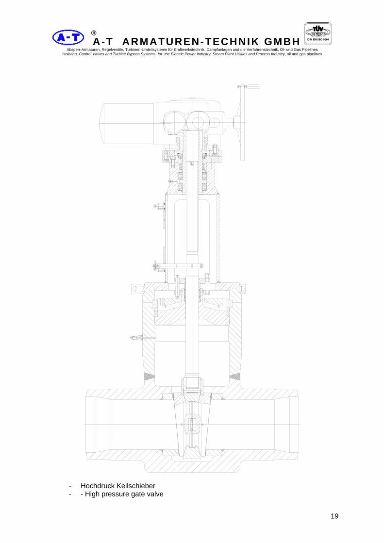
- Hochdruck Keilschieber - - High pressure gate valve

A-T ARMATUREN-TECHNIK GMBH Absperr-Armaturen, Regelventile, Turbinen-Umleitsysteme für Kraftwerkstechnik, Dampfanlagen und die Verfahrenstechnik, Öl- und Gas Pipelines
Isolating, Control Valves and Turbine Bypass Systems for the Electric Power Industry, Steam Plant Utilities and Process Industry, oil and gas pipelines
20
®
Keilschieber und Parallelschieber Aufbau und Wirkungsweise Alle Schieber sind als Doppelplatten - Keilschieber oder als Doppelplatten - Parallelschieber ausgebildet und werden für alle Druck- und Temperaturbereiche hergestellt. Sie sind in großen Stückzahlen seit ca. 50 Jahren im In- und Ausland im Betrieb. Die drucktragenden Teile bestehen aus Freiformschmiedestücken, die zu Gehäusen mit nur einer Rundnaht zusammengeschweißt werden. Größen und Nennweiten unserer Schieber finden Sie in den Maßtabellen. Langjährige Erfahrung bietet Gewähr für eine technisch ausgereifte und funktionssichere Konstruktion.
Das Gehäuse des Schiebers besteht aus dem in Durchflussrichtung geschmiedeten Mittelstück. Das in Rohrform geschmiedete Kopfstück wird mit dem Mittelstück verschweißt. Nur eine Rundnaht erlaubt die exakte Prüfung der Schweißnaht durch Röntgenstrahlen, Ultraschall - oder andere Kontrollverfahren. Dadurch werden sichere Festigkeitswerte im Armaturen- Gehäuse erreicht. Der Schieberverschluß ist als selbstdichtender Deckel ausgebildet. Die Abdichtung erfolgt durch vorgepresste Grafit - Packungen.
Der Schieberaufsatz ermöglicht immer den Direktaufbau eines Getriebes oder elektrischen Antriebes. Die Spindelschubkräfte werden in schweren Axial - Kugellagern und einem Radialkugellager abgefangen, die im Aufsatzkopf eingebaut sind. Die Spindeloberfläche ist auf Maß geschliffen und nachträglich durch Microfinish behandelt. Dadurch ergeben sich günstige Dicht- und Gleitverhältnisse im Packungsbereich der Spindel.
Wedge gate valve and Parallel slide gate valve Construction and Operation All gate valves are designed as double-plates gate valves or double-plates parallel slides valves and are manufactured for suiting all pressure and temperature ranges. They have been in operation in large numbers for over 40 years both at home and abroad. The pressurised parts consist of forgings which are welded to the body using only one circumferential weld seam. The sizes and nominal diameters of our gate valve are given in the tables of dimensions. Our many years experience is a guarantee of a High level of technical development and operationally safe design. The body is forged in the direction of flow to form a middle section. The bonnet section is made of forged tubing and is welded to middle section. A single circumferential weld seam enables the weld to be exactly tested by X - rays, ultrasonics or other method. This high quality ensures that the body has adequate strenght. The valve is sealed by means of a self- sealing cover. Pressed graphite packings are used to increase the effect of the seal. The yoke piece on top of the valves is designed in all cases to take a direct drive. The spindle thrust is absorbed by heavy duty axial ball bearings and a radial ball bearing which are fitted in the upper part of the yoke. The spindle surface is ground to size, after which it is treated by superfinishing. This ensures the most favourable conditions for sealing and sliding in the region of the spindle packing.

A-T ARMATUREN-TECHNIK GMBH Absperr-Armaturen, Regelventile, Turbinen-Umleitsysteme für Kraftwerkstechnik, Dampfanlagen und die Verfahrenstechnik, Öl- und Gas Pipelines
Isolating, Control Valves and Turbine Bypass Systems for the Electric Power Industry, Steam Plant Utilities and Process Industry, oil and gas pipelines
21
®
Die Dichtplatten sind in einem Plattenträger nach allen Richtungen frei pendelnd aufgehängt (s. Abb.). Die Druckübertragung erfolgt über großflächig tragende, gehärtete Kugelkalotten und Kugelpfannen, die in die Dichtplatten eingesetzt sind. Ein absolutes Dichtschließen kann durch relativ kleine Anpresskräfte erreicht werden. Deshalb bleiben Schließ- und Öffnungsmomente an unseren Schiebern klein. Eine Vergrößerung des Abstandes der Dichtplatten zueinander (z.B. nach Schleifarbeiten an den Dicht-flächen der Dichtringe) ist auf einfache Weise durch Hinterlegen von Zwischenscheiben hinter die Kugelkalotten möglich. Die Verbindung von Gehäuse mit Schieberaufsatz erfolgt durch zweiteilige Klammern, die sich bei Demontage und Montage leicht lösen lassen. Druck-tragende Schraubverbindungen mit Ausnahme der Stopfbüchse werden vermieden. Alle metallisch blanken Bauteile werden vor Auslieferung korrosionsgeschützt. Die Außenflächen der Armatur sind mit einer Grundfarbe versehen.
The sealing plates are suspended in a plate support so as to be self-aligning (see illustration). The pressure is transmitted by hardened ball segments and ball cups of large area which are inserted in the sealing discs. Absolutely tight sealing can be achieved by relatively Iow contact pressure. Our gate valves can therefore be opened and closed with little effort. It is possible to increase the spacing of the sealing plates (e. g. after grinding the sealing faces of the sealing rings) simply by inserting shims behind the ball Segments. The yoke piece on top of the valve is connected to the body by means of a two-part clamp which can easily be disconnected when dismantling or assembling. With the exception of the gland, there are no bolted connections under pressure. All machined metal parts are protected against corrosion before delivery. The external surface of the valve is primed.

A-T ARMATUREN-TECHNIK GMBH Absperr-Armaturen, Regelventile, Turbinen-Umleitsysteme für Kraftwerkstechnik, Dampfanlagen und die Verfahrenstechnik, Öl- und Gas Pipelines
Isolating, Control Valves and Turbine Bypass Systems for the Electric Power Industry, Steam Plant Utilities and Process Industry, oil and gas pipelines
22
®
Werkstoffe Werkstoffe werden nach Druck- und Temperaturbereichen ausgewählt. Vorzugsweise werden für die drucktragenden Teile die bekannten Kesselbau -und Rohrleitungsstähle verwendet. Die Spindeln bestehen aus korrosionsfesten Chrom- und Chrom-Molybdän-Stählen, bei hohen Temperaturbereichen aus hochwarmfestem Chromstahl. Als Packungen werden vorgepresste Grafitringe verwendet. Die Abschlussflächen der Schieber sind grundsätzlich mit Stellit gepanzert, feinst- geschliffen und geläppt. Auf Kundenwunsch werden unsere Schieber als Drosselschieber oder als Parallelschieber ausgebildet, wobei die Anpressung der Platten beim Parallel-schieber durch warmfeste Druckfedern erfolgt.
Materials Materials are chosen to suit the pressure and temperature ranges. For the pressurised parts, preference is given to the well known types of steel used in boiler and pipeline construction. The spindles are made from corrosion resistant chromium and chromiummolybdenum steel material, and from high heat resisting chromium steel for high temperatures. Grafit rings are used for packing. The joint faces of the valve are made in stellite, then precise grounded and lapped. Our gate valves can be supplied on request as throttle valves or parallel slide valves, the contact pressure of the discs in the case of the parallel gate valves being achieved by means of heat resistant compression springs.

A-T ARMATUREN-TECHNIK GMBH Absperr-Armaturen, Regelventile, Turbinen-Umleitsysteme für Kraftwerkstechnik, Dampfanlagen und die Verfahrenstechnik, Öl- und Gas Pipelines
Isolating, Control Valves and Turbine Bypass Systems for the Electric Power Industry, Steam Plant Utilities and Process Industry, oil and gas pipelines
23
®
Keilschieber Typ K1 aus Schmiedestahl DN 50 bis 600 PN 63 Gate valve type K1 of forged steel DN 50 to 600 PN 63
Abmessungen und Massen / Dimensions and weights Baulängen Face-to-face dimensions Flanscharmaturen in Anlehnung an: DIN 3202, Teil 1 Flanged ends as per similar to: DIN 3202, part 1 Einschweißarmaturen in Anlehnung an: DIN 3202, Teil 2 End-to-end dimension as per similar to: DIN 3202, part 2 Flansche, Abmessungen: DIN 2501, PN 63 Flanges, Dimensions as per: DIN 2501, PN 63 Schweißfugen: DIN 2559, Teil 1 Welding grooves: DIN 2559, part 1
Baumaße / Dimensions MasseReihe DN Weight L h1 h2 D b d1 a. (kg)
50 50 250 452 520 180 26 250 45 65 50 290 452 520 205 26 250 50 65 65 290 483 567 205 26 250 58 80 65 310 483 567 215 28 250 80 80 80 310 515 609 215 28 360 90 100 80 350 515 609 250 30 360 100 100 100 350 583 693 250 30 450 140 125 100 400 583 693 295 34 450 155 125 125 400 678 809 295 34 450 190
150 125 450 678 809 345 36 450 210 150 150 450 762 930 345 36 450 370
175 150 500 762 930 375 40 450 385 175 175 500 856 1045 375 40 520 400 200 175 550 856 1045 415 42 520 415 200 200 550 951 1166 415 42 640 560 250 200 650 951 1166 470 46 640 600 225 225 600 1008 1250 - - 720 650
1 250 225 650 1008 1250 470 46 720 790 250 250 650 1077 1344 470 46 720 775 300 250 750 1077 1344 530 52 720 825 275 275 700 1171 1465 - - 800 950 300 275 750 1171 1465 530 52 800 960 300 300 750 1234 1549 530 52 800 975 350 300 850 1234 1549 600 56 800 1060 350 350 850 1491 1869 600 56 900 1900 400 350 950 1491 1869 670 60 900 2050 400 400 950 1659 2090 670 60 1000 2150 450 400 1050 1659 2090 - - 1000 - 450 450 1050 1806 2289 - - 1000 - 500 450 1150 1806 2289 - - 1000 - 500 500 1150 1959 2499 - - 1000 - 550 500 1250 1959 2499 - - 1000 - 600 500 1350 1959 2499 - - 1000 - 550 550 1350 2258 2846 - - 1000 - 600 550 1400 2258 2846 - - 1000 - 600 600 1450 2331 2961 - - 1000 -
Änderungen vorbehalten / Rights reserved to change specification without notice Größere Nennweiten, höhere Drücke und Baulängen nach DIN oder ANSI auf Anfrage / Bigger diameters nominal, higher pressure and dimensions to DIN or ANSI on request

A-T ARMATUREN-TECHNIK GMBH Absperr-Armaturen, Regelventile, Turbinen-Umleitsysteme für Kraftwerkstechnik, Dampfanlagen und die Verfahrenstechnik, Öl- und Gas Pipelines
Isolating, Control Valves and Turbine Bypass Systems for the Electric Power Industry, Steam Plant Utilities and Process Industry, oil and gas pipelines
24
®
Werkstoffe / Materials Pos. Nr. Bauteil -10°C bis / to 400°C -10°C bis / to 500°C Item No Component Werkstoff
MaterialStoff - Nr.
Material-No.Werkstoff Material
Stoff - Nr. Material-No.
1 Gehäuse / Body C22.8 1.0460 15Mo3 1.5415 2 Gehäusekopf / Body C22.8 1.0460 15Mo3 1.5415 3 Sitzring / Seat ring C22.8 / Stellit 1.0460 15Mo3 / Stellit 1.5415 4 Gehäuseverschluß / seal bonnet C22.8 1.0460 15Mo3 1.5415 5 Dichtplatte / Wedge C22.8 / Stellit 1.0460 15Mo3 / Stellit 1.5415 10 Spindel / Stem X20CrNi17 2 1.4057 X20CrMoV12 1 1.4922 12 Packungsring / Packing ring Grafit / 1.4541 - Grafit / 1.4541 - 13 Druckring / Thrust ring C22.8 1.0460 15Mo3 1.5415 14 2tlg. Klammer / Clamp connection C22.8 1.0460 15Mo3 1.5415 17 4tlg. Ring / Segmental thrust ring C22.8 1.0460 15Mo3 1.5415 19 Schraubenbolzen / Stud bolt 21CrMoV5 7 1:7709 21CrMoV5 7 1:7709 20 Skt.-Mutter / Heagon Nut 24CrMo5 1.7258 24CrMo5 1.7258 21 Sperrscheibe / Disc C22.8 1.0460 15Mo3 1.5415 22 Stopfbuchsbrücke / Gland flange C22.8 1.0460 15Mo3 1.5415 23 Druckschraube / Thrust screw 21CrMoV5 7 1:7709 21CrMoV5 7 1:7709 28 Packungssatz / Packing set Grafit - Grafit - 30 Aufsatz / Bonnet C22.8 1.0460 15Mo3 1.5415 36 Handrad / Hand wheel GG-25 0.6025 GG-25 0.6025 38 Gewindebuchse / Yoke G -CuAl10Ni 2.0966 X20CrMoV12 1 1.4922
Pos. Nr. Bauteil -10°C bis / to 550°C -10°C bis / to 550°C Item No Component Werkstoff
MaterialStoff - Nr.
Material-No.Werkstoff Material
Stoff - Nr. Material-No.
1 Gehäuse / Body 13CrMo4 4 1.7335 10CrMo9 10 1.7380 2 Gehäusekopf / Body 13CrMo4 4 1.7335 10CrMo9 10 1.7380 3 Sitzring / Seat ring 13CrMo4 4 / Stellit 1.7335 10CrMo9 10 / Stellit 1.7380 4 Gehäuseverschluß / seal bonnet 13CrMo4 4 1.7335 10CrMo9 10 1.7380 5 Dichtplatte / Wedge 13CrMo4 4 / Stellit 1.7335 10CrMo9 10 / Stellit 1.7380 10 Spindel / Stem X20CrMoV12 1 1.4922 X20CrMoV12 1 1.4922 12 Packungsring / Packing ring Grafit / 1.4541 - Grafit / 1.4541 - 13 Druckring / Thrust ring 13CrMo4 4 1.7335 10CrMo9 10 1.7380 14 2tlg. Klammer / Clamp connection 15Mo3 1.5415 13CrMo4 4 1.7335 17 4tlg. Ring / Segmental thrust ring 13CrMo4 4 1.7335 10CrMo9 10 1.7380 19 Schraubenbolzen / Stud bolt 21CrMoV5 7 1:7709 21CrMoV5 7 1:7709 20 Skt.-Mutter / Heagon Nut 24CrMo5 1.7258 24CrMo5 1.7258 21 Sperrscheibe / Disc 13CrMo4 4 1.7335 13CrMo4 4 1.7335 22 Stopfbuchsbrücke / Gland flange 15Mo3 1.5415 13CrMo4 4 1.7335 23 Druckschraube / Thrust screw 21CrMoV5 7 1:7709 21CrMoV5 7 1:7709 28 Packungssatz / Packing set Grafit - Grafit - 30 Aufsatz / Bonnet 15Mo3 1.5415 13CrMo4 4 1.7335 36 Handrad / Hand wheel GG-25 0.6025 GG-25 0.6025 38 Gewindebuchse / Yoke X20CrMoV12 1 1.4922 X20CrMoV12 1 1.4922
Weitere Werkstoffe auf Anfrage / Further materials on request Druck-Temperatur-Zuordnung / Pressure-Temperature-Rating Siehe Kennblatt / See technical data sheet Einsatzbereiche / Application Für nichtaggressive und aggressive Flüssigkeiten und Gase / For non - corrosive and corrosive liquids and gases Anfrage und Bestellung / Orders and inquiries Bei Anfrage und Bestellung werden benötigt: Nenndruck, Nennweite, Gehäusewerkstoff, maximale Betriebstemperatur, maximaler Betriebsdruck, Rohranschlußmaße für Einschweißenden, Betriebsmedium, Prüf- und Abnahmebedingungen sowie Art des Abnahmezeugnisses mach DIN50049 / EN 10204 und kundenspezifische Wünsche. Following data ar requiered for request and order: nominal pressure, nominal diameter, body material, maximum operating temperature, maximum operating pressure, pipe connection dimensions for butt - welding ends, operating medium, test and acceptance conditions, kind of acceptance certificate to DIN 50049 / EN 10204 and other customer - specific wishes. Prüfung und Abnahme / testing and acceptance Für die Prüfung und Abnahme gelten die Vorschriften nach DIN 3230 sowie kundenspecifische Vereinbarungen. The regulation in DIN 3230 and specific agreements with customer shall form the basis for testing and acceptance.

A-T ARMATUREN-TECHNIK GMBH Absperr-Armaturen, Regelventile, Turbinen-Umleitsysteme für Kraftwerkstechnik, Dampfanlagen und die Verfahrenstechnik, Öl- und Gas Pipelines
Isolating, Control Valves and Turbine Bypass Systems for the Electric Power Industry, Steam Plant Utilities and Process Industry, oil and gas pipelines
25
®
Keilschieber Typ K2 aus Schmiedestahl DN 50 bis 600 PN 100
Gate valve type K2 of forged steel DN 50 to 600 PN 100
Abmessungen und Massen / Dimensions and weights Baulängen Face-to-face dimensions Flanscharmaturen in Anlehnung an: DIN 3202, Teil 1 Flanged ends as per similar to: DIN 3202, part 1 Einschweißarmaturen in Anlehnung an: DIN 3202, Teil 2 End-to-end dimension as per similar to: DIN 3202, part 2 Flansche, Abmessungen: DIN 2501, PN 100 Flanges, Dimensions as per: DIN 2501, PN 100 Schweißfugen: DIN 2559, Teil 1 Welding grooves: DIN 2559, part 1
Baumaße / Dimensions MasseReihe DN Weight L h1 h2 D b d1 a. (kg) 50 50 250 452 520 195 28 250 45 65 50 290 452 520 220 30 250 50 65 65 290 483 567 220 30 360 60 80 65 310 483 567 230 32 360 80 80 80 310 557 651 230 32 450 90 100 80 350 557 651 265 36 450 100 100 100 350 609 721 265 36 450 140 125 100 400 609 721 315 40 450 155 125 125 400 704 845 315 40 520 190 150 125 450 704 845 355 44 520 210 150 150 450 804 970 355 44 640 370 175 150 500 804 970 385 48 640 385 175 175 500 877 1066 385 48 720 400 200 175 550 877 1066 430 52 720 415 200 200 550 951 1166 430 52 800 560 250 200 650 951 1166 505 60 800 600 225 225 600 1029 1279 - - 900 6502 250 225 650 1029 1279 505 60 900 790 250 250 650 1103 1386 505 60 900 775 300 250 750 1103 1368 585 68 900 825 275 275 750 1187 1481 - - 900 950 300 275 750 1187 1481 585 68 900 960 300 300 750 1276 1591 585 68 900 975 350 300 850 1276 1591 655 74 900 1060 350 350 850 1491 1869 655 74 1000 1900 400 350 950 1491 1869 - - 1000 2050 400 400 950 1659 2090 - - 1000 2150 450 400 1050 1659 2090 - - 1000 - 450 450 1050 1806 2289 - - 1000 - 500 450 1150 1806 2289 - - 1000 - 500 500 1150 1974 2515 - - 1000 - 550 500 1250 1974 2515 - - 1000 - 600 500 1350 1974 2515 - - 1000 - 550 550 1350 2310 2909 - - 1000 - 600 550 1400 2310 2909 - - 1000 - 600 600 1500 2646 3297 - - 1000 -
Änderungen vobehalten / Right reserved to change specification without notice Größere Nennweiten, höhere Drücke und Baulängen nach DIN oder ANSI auf Anfrage / Bigger diameters nominal, higher pressure and dimensions to DIN or ANSI on request

A-T ARMATUREN-TECHNIK GMBH Absperr-Armaturen, Regelventile, Turbinen-Umleitsysteme für Kraftwerkstechnik, Dampfanlagen und die Verfahrenstechnik, Öl- und Gas Pipelines
Isolating, Control Valves and Turbine Bypass Systems for the Electric Power Industry, Steam Plant Utilities and Process Industry, oil and gas pipelines
26
®
Werkstoffe / Materials Pos. Nr. Bauteil -10°C bis / to 400°C -10°C bis / to 500°C Item No Component Werkstoff
MaterialStoff - Nr.
Material-No.Werkstoff Material
Stoff - Nr. Material-No.
1 Gehäuse / Body C22.8 1.0460 15Mo3 1.5415 2 Gehäusekopf / Body C22.8 1.0460 15Mo3 1.5415 3 Sitzring / Seat ring C22.8 / Stellit 1.0460 15Mo3 / Stellit 1.5415 4 Gehäuseverschluß / seal bonnet C22.8 1.0460 15Mo3 1.5415 5 Dichtplatte / Wedge C22.8 / Stellit 1.0460 15Mo3 / Stellit 1.5415 10 Spindel / Stem X20CrNi17 2 1.4057 X20CrMoV12 1 1.4922 12 Packungsring / Packing ring Grafit / 1.4541 - Grafit / 1.4541 - 13 Druckring / Thrust ring C22.8 1.0460 15Mo3 1.5415 14 2tlg. Klammer / Clamp connection C22.8 1.0460 15Mo3 1.5415 17 4tlg. Ring / Segmental thrust ring C22.8 1.0460 15Mo3 1.5415 19 Schraubenbolzen / Stud bolt 21CrMoV5 7 1:7709 21CrMoV5 7 1:7709 20 Skt.-Mutter / Heagon Nut 24CrMo5 1.7258 24CrMo5 1.7258 21 Sperrscheibe / Disc C22.8 1.0460 15Mo3 1.5415 22 Stopfbuchsbrücke / Gland flange C22.8 1.0460 15Mo3 1.5415 23 Druckschraube / Thrust screw 21CrMoV5 7 1:7709 21CrMoV5 7 1:7709 28 Packungssatz / Packing set Grafit - Grafit - 30 Aufsatz / Bonnet C22.8 1.0460 15Mo3 1.5415 36 Handrad / Hand wheel GG-25 0.6025 GG-25 0.6025 38 Gewindebuchse / Yoke G -CuAl10Ni 2.0966 X20CrMoV12 1 1.4922
Pos. Nr. Bauteil -10°C bis / to 550°C -10°C bis / to 550°C Item No Component Werkstoff
MaterialStoff - Nr.
Material-No.Werkstoff Material
Stoff - Nr. Material-No.
1 Gehäuse / Body 13CrMo4 4 1.7335 10CrMo9 10 1.7380 2 Gehäusekopf / Body 13CrMo4 4 1.7335 10CrMo9 10 1.7380 3 Sitzring / Seat ring 13CrMo4 4 / Stellit 1.7335 10CrMo9 10 / Stellit 1.7380 4 Gehäuseverschluß / seal bonnet 13CrMo4 4 1.7335 10CrMo9 10 1.7380 5 Dichtplatte / Wedge 13CrMo4 4 / Stellit 1.7335 10CrMo9 10 / Stellit 1.7380 10 Spindel / Stem X20CrMoV12 1 1.4922 X20CrMoV12 1 1.4922 12 Packungsring / Packing ring Grafit / 1.4541 - Grafit / 1.4541 - 13 Druckring / Thrust ring 13CrMo4 4 1.7335 10CrMo9 10 1.7380 14 2tlg. Klammer / Clamp connection 15Mo3 1.5415 13CrMo4 4 1.7335 17 4tlg. Ring / Segmental thrust ring 13CrMo4 4 1.7335 10CrMo9 10 1.7380 19 Schraubenbolzen / Stud bolt 21CrMoV5 7 1:7709 21CrMoV5 7 1:7709 20 Skt.-Mutter / Heagon Nut 24CrMo5 1.7258 24CrMo5 1.7258 21 Sperrscheibe / Disc 13CrMo4 4 1.7335 13CrMo4 4 1.7335 22 Stopfbuchsbrücke / Gland flange 15Mo3 1.5415 13CrMo4 4 1.7335 23 Druckschraube / Thrust screw 21CrMoV5 7 1:7709 21CrMoV5 7 1:7709 28 Packungssatz / Packing set Grafit - Grafit - 30 Aufsatz / Bonnet 15Mo3 1.5415 13CrMo4 4 1.7335 36 Handrad / Hand wheel GG-25 0.6025 GG-25 0.6025 38 Gewindebuchse / Yoke X20CrMoV12 1 1.4922 X20CrMoV12 1 1.4922
Weitere Werkstoffe auf Anfrage / Further materials on request Druck-Temperatur-Zuordnung / Pressure-Temperature-Rating Siehe Kennblatt / See technical data sheet Einsatzbereiche / Application Für nichtaggressive und aggressive Flüssigkeiten und Gase / For non - corrosive and corrosive liquids and gases Anfrage und Bestellung / Orders and inquiries Bei Anfrage und Bestellung werden benötigt: Nenndruck, Nennweite, Gehäusewerkstoff, maximale Betriebstemperatur, maximaler Betriebsdruck, Rohranschlußmaße für Einschweißenden, Betriebsmedium, Prüf- und Abnahmebedingungen sowie Art des Abnahmezeugnisses mach DIN50049 / EN 10204 und kundenspezifische Wünsche. Following data are required for request and order: nominal pressure, nominal diameter, body material, maximum operating temperature, maximum operating pressure, pipe connection dimensions for butt - welding ends, operating medium, test and acceptance conditions, kind of acceptance certificate to DIN 50049 / EN 10204 and other customer - specific wishes. Prüfung und Abnahme / testing and acceptance Für die Prüfung und Abnahme gelten die Vorschriften nach DIN 3230 sowie kundenspecifische Vereinbarungen. The regulation in DIN 3230 and specific agreements with customer shall form the basis for testing and acceptance.

A-T ARMATUREN-TECHNIK GMBH Absperr-Armaturen, Regelventile, Turbinen-Umleitsysteme für Kraftwerkstechnik, Dampfanlagen und die Verfahrenstechnik, Öl- und Gas Pipelines
Isolating, Control Valves and Turbine Bypass Systems for the Electric Power Industry, Steam Plant Utilities and Process Industry, oil and gas pipelines
27
®
Werkstoffe / Materials Pos. Nr. Bauteil -10°C bis / to 400°C -10°C bis / to 500°C Item No Component Werkstoff
MaterialStoff - Nr.
Material-No.Werkstoff Material
Stoff - Nr. Material-No.
1 Gehäuse / Body C22.8 1.0460 15Mo3 1.5415 2 Gehäusekopf / Body C22.8 1.0460 15Mo3 1.5415 3 Sitzring / Seat ring C22.8 / Stellit 1.0460 15Mo3 / Stellit 1.5415 4 Gehäuseverschluß / seal bonnet C22.8 1.0460 15Mo3 1.5415 5 Dichtplatte / Wedge C22.8 / Stellit 1.0460 15Mo3 / Stellit 1.5415 10 Spindel / Stem X20CrNi17 2 1.4057 X20CrMoV12 1 1.4922 12 Packungsring / Packing ring Grafit / 1.4541 - Grafit / 1.4541 - 13 Druckring / Thrust ring C22.8 1.0460 15Mo3 1.5415 14 2tlg. Klammer / Clamp connection C22.8 1.0460 15Mo3 1.5415 17 4tlg. Ring / Segmental thrust ring C22.8 1.0460 15Mo3 1.5415 19 Schraubenbolzen / Stud bolt 21CrMoV5 7 1:7709 21CrMoV5 7 1:7709 20 Skt.-Mutter / Heagon Nut 24CrMo5 1.7258 24CrMo5 1.7258 21 Sperrscheibe / Disc C22.8 1.0460 15Mo3 1.5415 22 Stopfbuchsbrücke / Gland flange C22.8 1.0460 15Mo3 1.5415 23 Druckschraube / Thrust screw 21CrMoV5 7 1:7709 21CrMoV5 7 1:7709 28 Packungssatz / Packing set Grafit - Grafit - 30 Aufsatz / Bonnet C22.8 1.0460 15Mo3 1.5415 36 Handrad / Hand wheel GG-25 0.6025 GG-25 0.6025 38 Gewindebuchse / Yoke G -CuAl10Ni 2.0966 X20CrMoV12 1 1.4922
Pos. Nr. Bauteil -10°C bis / to 550°C -10°C bis / to 550°C Item No Component Werkstoff
MaterialStoff - Nr.
Material-No.Werkstoff Material
Stoff - Nr. Material-No.
1 Gehäuse / Body 13CrMo4 4 1.7335 10CrMo9 10 1.7380 2 Gehäusekopf / Body 13CrMo4 4 1.7335 10CrMo9 10 1.7380 3 Sitzring / Seat ring 13CrMo4 4 / Stellit 1.7335 10CrMo9 10 / Stellit 1.7380 4 Gehäuseverschluß / seal bonnet 13CrMo4 4 1.7335 10CrMo9 10 1.7380 5 Dichtplatte / Wedge 13CrMo4 4 / Stellit 1.7335 10CrMo9 10 / Stellit 1.7380 10 Spindel / Stem X20CrMoV12 1 1.4922 X20CrMoV12 1 1.4922 12 Packungsring / Packing ring Grafit / 1.4541 - Grafit / 1.4541 - 13 Druckring / Thrust ring 13CrMo4 4 1.7335 10CrMo9 10 1.7380 14 2tlg. Klammer / Clamp connection 15Mo3 1.5415 13CrMo4 4 1.7335 17 4tlg. Ring / Segmental thrust ring 13CrMo4 4 1.7335 10CrMo9 10 1.7380 19 Schraubenbolzen / Stud bolt 21CrMoV5 7 1:7709 21CrMoV5 7 1:7709 20 Skt.-Mutter / Heagon Nut 24CrMo5 1.7258 24CrMo5 1.7258 21 Sperrscheibe / Disc 13CrMo4 4 1.7335 13CrMo4 4 1.7335 22 Stopfbuchsbrücke / Gland flange 15Mo3 1.5415 13CrMo4 4 1.7335 23 Druckschraube / Thrust screw 21CrMoV5 7 1:7709 21CrMoV5 7 1:7709 28 Packungssatz / Packing set Grafit - Grafit - 30 Aufsatz / Bonnet 15Mo3 1.5415 13CrMo4 4 1.7335 36 Handrad / Hand wheel GG-25 0.6025 GG-25 0.6025 38 Gewindebuchse / Yoke X20CrMoV12 1 1.4922 X20CrMoV12 1 1.4922
Weitere Werkstoffe auf Anfrage / Further materials on request Druck-Temperatur-Zuordnung / Pressure-Temperature-Rating Siehe Kennblatt / See technical data sheet Einsatzbereiche / Application Für nichtaggressive und aggressive Flüssigkeiten und Gase / For non - corrosive and corrosive liquids and gases Anfrage und Bestellung / Orders and inquiries Bei Anfrage und Bestellung werden benötigt: Nenndruck, Nennweite, Gehäusewerkstoff, maximale Betriebstemperatur, maximaler Betriebsdruck, Rohranschlussmaße für Einschweißenden, Betriebsmedium, Prüf- und Abnahmebedingungen sowie Art des Abnahmezeugnisses mach DIN50049 / EN 10204 und kundenspezifische Wünsche. Following data are required for request and order: nominal pressure, nominal diameter, body material, maximum operating temperature, maximum operating pressure, pipe connection dimensions for butt - welding ends, operating medium, test and acceptance conditions, kind of acceptance certificate to DIN 50049 / EN 10204 and other customer - specific wishes. Prüfung und Abnahme / testing and acceptance Für die Prüfung und Abnahme gelten die Vorschriften nach DIN 3230 sowie kundenspecifische Vereinbarungen. The regulation in DIN 3230 and specific agreements with customer shall form the basis for testing and acceptance.
A-T ARMATUREN-TECHNIK GMBH Absperr-Armaturen, Regelventile, Turbinen-Umleitsysteme für Kraftwerkstechnik, Dampfanlagen und die Verfahrenstechnik, Öl- und Gas Pipelines
Isolating, Control Valves and Turbine Bypass Systems for the Electric Power Industry, Steam Plant Utilities and Process Industry, oil and gas pipelines
28
®
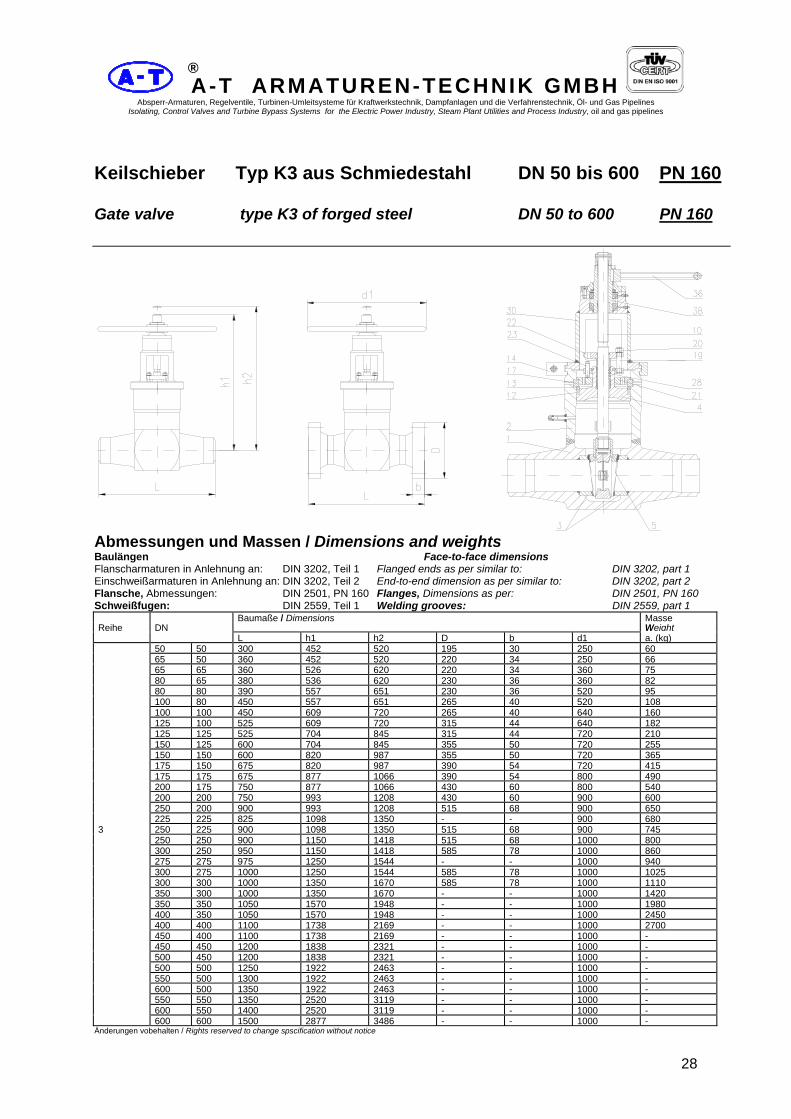
Keilschieber Typ K3 aus Schmiedestahl DN 50 bis 600 PN 160 Gate valve type K3 of forged steel DN 50 to 600 PN 160
Abmessungen und Massen / Dimensions and weights Baulängen Face-to-face dimensions Flanscharmaturen in Anlehnung an: DIN 3202, Teil 1 Flanged ends as per similar to: DIN 3202, part 1 Einschweißarmaturen in Anlehnung an: DIN 3202, Teil 2 End-to-end dimension as per similar to: DIN 3202, part 2 Flansche, Abmessungen: DIN 2501, PN 160 Flanges, Dimensions as per: DIN 2501, PN 160 Schweißfugen: DIN 2559, Teil 1 Welding grooves: DIN 2559, part 1
Baumaße / Dimensions MasseReihe DN Weight L h1 h2 D b d1 a. (kg) 50 50 300 452 520 195 30 250 60 65 50 360 452 520 220 34 250 66 65 65 360 526 620 220 34 360 75 80 65 380 536 620 230 36 360 82 80 80 390 557 651 230 36 520 95 100 80 450 557 651 265 40 520 108 100 100 450 609 720 265 40 640 160 125 100 525 609 720 315 44 640 182 125 125 525 704 845 315 44 720 210 150 125 600 704 845 355 50 720 255 150 150 600 820 987 355 50 720 365 175 150 675 820 987 390 54 720 415 175 175 675 877 1066 390 54 800 490 200 175 750 877 1066 430 60 800 540 200 200 750 993 1208 430 60 900 600 250 200 900 993 1208 515 68 900 650 225 225 825 1098 1350 - - 900 6803 250 225 900 1098 1350 515 68 900 745 250 250 900 1150 1418 515 68 1000 800 300 250 950 1150 1418 585 78 1000 860 275 275 975 1250 1544 - - 1000 940 300 275 1000 1250 1544 585 78 1000 1025 300 300 1000 1350 1670 585 78 1000 1110 350 300 1000 1350 1670 - - 1000 1420 350 350 1050 1570 1948 - - 1000 1980 400 350 1050 1570 1948 - - 1000 2450 400 400 1100 1738 2169 - - 1000 2700 450 400 1100 1738 2169 - - 1000 - 450 450 1200 1838 2321 - - 1000 - 500 450 1200 1838 2321 - - 1000 - 500 500 1250 1922 2463 - - 1000 - 550 500 1300 1922 2463 - - 1000 - 600 500 1350 1922 2463 - - 1000 - 550 550 1350 2520 3119 - - 1000 - 600 550 1400 2520 3119 - - 1000 - 600 600 1500 2877 3486 - - 1000 -
Änderungen vobehalten / Rights reserved to change spscification without notice

A-T ARMATUREN-TECHNIK GMBH Absperr-Armaturen, Regelventile, Turbinen-Umleitsysteme für Kraftwerkstechnik, Dampfanlagen und die Verfahrenstechnik, Öl- und Gas Pipelines
Isolating, Control Valves and Turbine Bypass Systems for the Electric Power Industry, Steam Plant Utilities and Process Industry, oil and gas pipelines
29
®
Größere Nennweiten, höhere Drücke und Baulängen nach DIN oder ANSI auf Anfrage / Bigger diameters nominal, higher pressure and dimensions to DIN or ANSI on request
Werkstoffe / Materials Pos. Nr. Bauteil -10°C bis / to 400°C -10°C bis / to 500°C Item No Component Werkstoff
MaterialStoff - Nr.
Material-No.Werkstoff Material
Stoff - Nr. Material-No.
1 Gehäuse / Body C22.8 1.0460 15Mo3 1.5415 2 Gehäusekopf / Body C22.8 1.0460 15Mo3 1.5415 3 Sitzring / Seat ring C22.8 / Stellit 1.0460 15Mo3 / Stellit 1.5415 4 Gehäuseverschluß / seal bonnet C22.8 1.0460 15Mo3 1.5415 5 Dichtplatte / Wedge C22.8 / Stellit 1.0460 15Mo3 / Stellit 1.5415 10 Spindel / Stem X20CrNi17 2 1.4057 X20CrMoV12 1 1.4922 12 Packungsring / Packing ring Grafit / 1.4541 - Grafit / 1.4541 - 13 Druckring / Thrust ring C22.8 1.0460 15Mo3 1.5415 14 2tlg. Klammer / Clamp connection C22.8 1.0460 15Mo3 1.5415 17 4tlg. Ring / Segmental thrust ring C22.8 1.0460 15Mo3 1.5415 19 Schraubenbolzen / Stud bolt 21CrMoV5 7 1:7709 21CrMoV5 7 1:7709 20 Skt.-Mutter / Heagon Nut 24CrMo5 1.7258 24CrMo5 1.7258 21 Sperrscheibe / Disc C22.8 1.0460 15Mo3 1.5415 22 Stopfbuchsbrücke / Gland flange C22.8 1.0460 15Mo3 1.5415 23 Druckschraube / Thrust screw 21CrMoV5 7 1:7709 21CrMoV5 7 1:7709 28 Packungssatz / Packing set Grafit - Grafit - 30 Aufsatz / Bonnet C22.8 1.0460 15Mo3 1.5415 36 Handrad / Hand wheel GG-25 0.6025 GG-25 0.6025 38 Gewindebuchse / Yoke G -CuAl10Ni 2.0966 X20CrMoV12 1 1.4922
Pos. Nr. Bauteil -10°C bis / to 550°C -10°C bis / to 550°C Item No Component Werkstoff
MaterialStoff - Nr.
Material-No.Werkstoff Material
Stoff - Nr. Material-No.
1 Gehäuse / Body 13CrMo4 4 1.7335 10CrMo9 10 1.7380 2 Gehäusekopf / Body 13CrMo4 4 1.7335 10CrMo9 10 1.7380 3 Sitzring / Seat ring 13CrMo4 4 / Stellit 1.7335 10CrMo9 10 / Stellit 1.7380 4 Gehäuseverschluß / seal bonnet 13CrMo4 4 1.7335 10CrMo9 10 1.7380 5 Dichtplatte / Wedge 13CrMo4 4 / Stellit 1.7335 10CrMo9 10 / Stellit 1.7380 10 Spindel / Stem X20CrMoV12 1 1.4922 X20CrMoV12 1 1.4922 12 Packungsring / Packing ring Grafit / 1.4541 - Grafit / 1.4541 - 13 Druckring / Thrust ring 13CrMo4 4 1.7335 10CrMo9 10 1.7380 14 2tlg. Klammer / Clamp connection 15Mo3 1.5415 13CrMo4 4 1.7335 17 4tlg. Ring / Segmental thrust ring 13CrMo4 4 1.7335 10CrMo9 10 1.7380 19 Schraubenbolzen / Stud bolt 21CrMoV5 7 1:7709 21CrMoV5 7 1:7709 20 Skt.-Mutter / Heagon Nut 24CrMo5 1.7258 24CrMo5 1.7258 21 Sperrscheibe / Disc 13CrMo4 4 1.7335 13CrMo4 4 1.7335 22 Stopfbuchsbrücke / Gland flange 15Mo3 1.5415 13CrMo4 4 1.7335 23 Druckschraube / Thrust screw 21CrMoV5 7 1:7709 21CrMoV5 7 1:7709 28 Packungssatz / Packing set Grafit - Grafit - 30 Aufsatz / Bonnet 15Mo3 1.5415 13CrMo4 4 1.7335 36 Handrad / Hand wheel GG-25 0.6025 GG-25 0.6025 38 Gewindebuchse / Yoke X20CrMoV12 1 1.4922 X20CrMoV12 1 1.4922
Weitere Werkstoffe auf Anfrage / Further materials on request Druck-Temperatur-Zuordnung / Pressure-Temperature-Rating Siehe Kennblatt / See technical data sheet Einsatzbereiche / Application Für nichtaggressive und aggressive Flüssigkeiten und Gase / For non - corrosive and corrosive liquids and gases Anfrage und Bestellung / Orders and inquiries Bei Anfrage und Bestellung werden benötigt: Nenndruck, Nennweite, Gehäusewerkstoff, maximale Betriebstemperatur, maximaler Betriebsdruck, Rohranschlußmaße für Einschweißenden, Betriebsmedium, Prüf- und Abnahmebedingungen sowie Art des Abnahmezeugnisses mach DIN50049 / EN 10204 und kundenspezifische Wünsche. Following data ar requiered for request and order: nominal pressure, nominal diameter, body material, maximum operating temperature, maximum operating pressure, pipe connection dimensions for batt - welding ends, operating medium, test and acceptance conditions, kind of acceptance certificate to DIN 50049 / EN 10204 and other customer - specific wishes. Prüfung und Abnahme / testing and acceptance Für die Prüfung und Abnahme gelten die Vorschriften nach DIN 3230 sowie kundenspecifische Vereinbarungen. The regulation in DIN 3230 and specific agreements with customer shall form the basis for testing and acceptance.

A-T ARMATUREN-TECHNIK GMBH Absperr-Armaturen, Regelventile, Turbinen-Umleitsysteme für Kraftwerkstechnik, Dampfanlagen und die Verfahrenstechnik, Öl- und Gas Pipelines
Isolating, Control Valves and Turbine Bypass Systems for the Electric Power Industry, Steam Plant Utilities and Process Industry, oil and gas pipelines
30
®
Keilschieber Typ K4 aus Schmiedestahl DN 50 bis 450 PN 250 Gate valve type K4 of forged steel DN 50 to 450 PN 250
Abmessungen und Massen / Dimensions and weights Baulängen Face-to-face dimensions Flanscharmaturen in Anlehnung an: DIN 3202, Teil 1 Flanged ends as per similar to: DIN 3202, part 1 Einschweißarmaturen in Anlehnung an: DIN 3202, Teil 2 End-to-end dimension as per similar to: DIN 3202, part 2 Flansche, Abmessungen: DIN 2501, PN 250 Flanges, Dimensions as per: DIN 2501, PN 250 Schweißfugen: DIN 2559, Teil 1 Welding grooves: DIN 2559, part 1
Baumaße / Dimensions MasseReihe DN Weight L h1 h2 D b d1 a. (kg) 50 50 350 452 520 200 38 360 72 65 50 425 452 520 230 42 360 80 65 65 425 542 625 230 42 450 90 80 65 470 541 625 255 46 450 98 80 80 470 588 683 255 46 520 110 100 80 550 588 683 300 54 520 128 100 100 550 678 798 300 54 720 170 125 100 650 678 798 340 60 720 200 125 125 650 741 882 340 60 800 235 150 125 750 741 882 390 68 800 320 150 150 750 820 987 390 68 800 430 175 150 850 820 987 430 74 800 500 175 175 850 966 1166 430 74 900 580 200 175 950 966 1166 485 82 900 6854 200 200 950 1103 1334 485 82 900 805 250 200 1150 1103 1334 585 100 900 895 225 225 1050 1197 1449 - - 1000 970 250 225 1150 1197 1449 585 100 1000 1040 250 250 1150 1245 1518 585 100 1000 1120 300 250 1350 1245 1518 690 120 1000 1250 275 275 1250 1344 1644 - - 1000 1400 300 275 1350 1344 1644 690 120 1000 1610 300 300 1350 1407 1738 690 120 1000 1830 350 300 1350 1407 1738 - - 1000 2235 350 350 1400 1707 2106 - - 1000 2800 400 350 1400 1707 2106 - - 1000 3305 400 400 1450 1943 2400 - - 1000 3710 450 400 1450 1943 2400 - - 1000 - 450 450 1500 2048 2541 - - 1000 -
Änderungen vobehalten / Rights reserved to change specification without notice Größere Nennweiten, höhere Drücke und Baulängen nach DIN oder ANSI auf Anfrage / Bigger diameters nominal, higher pressure and dimensions to DIN or ANSI on request

A-T ARMATUREN-TECHNIK GMBH Absperr-Armaturen, Regelventile, Turbinen-Umleitsysteme für Kraftwerkstechnik, Dampfanlagen und die Verfahrenstechnik, Öl- und Gas Pipelines
Isolating, Control Valves and Turbine Bypass Systems for the Electric Power Industry, Steam Plant Utilities and Process Industry, oil and gas pipelines
31
®
Werkstoffe / Materials Pos. Nr. Bauteil -10°C bis / to 400°C -10°C bis / to 500°C Item No Component Werkstoff
MaterialStoff - Nr.
Material-No.Werkstoff Material
Stoff - Nr. Material-No.
1 Gehäuse / Body C22.8 1.0460 15Mo3 1.5415 2 Gehäusekopf / Body C22.8 1.0460 15Mo3 1.5415 3 Sitzring / Seat ring C22.8 / Stellit 1.0460 15Mo3 / Stellit 1.5415 4 Gehäuseverschluß / seal bonnet C22.8 1.0460 15Mo3 1.5415 5 Dichtplatte / Wedge C22.8 / Stellit 1.0460 15Mo3 / Stellit 1.5415 10 Spindel / Stem X20CrNi17 2 1.4057 X20CrMoV12 1 1.4922 12 Packungsring / Packing ring Grafit / 1.4541 - Grafit / 1.4541 - 13 Druckring / Thrust ring C22.8 1.0460 15Mo3 1.5415 14 2tlg. Klammer / Clamp connection C22.8 1.0460 15Mo3 1.5415 17 4tlg. Ring / Segmental thrust ring C22.8 1.0460 15Mo3 1.5415 19 Schraubenbolzen / Stud bolt 21CrMoV5 7 1:7709 21CrMoV5 7 1:7709 20 Skt.-Mutter / Heagon Nut 24CrMo5 1.7258 24CrMo5 1.7258 21 Sperrscheibe / Disc C22.8 1.0460 15Mo3 1.5415 22 Stopfbuchsbrücke / Gland flange C22.8 1.0460 15Mo3 1.5415 23 Druckschraube / Thrust screw 21CrMoV5 7 1:7709 21CrMoV5 7 1:7709 28 Packungssatz / Packing set Grafit - Grafit - 30 Aufsatz / Bonnet C22.8 1.0460 15Mo3 1.5415 36 Handrad / Hand wheel GG-25 0.6025 GG-25 0.6025 38 Gewindebuchse / Yoke G -CuAl10Ni 2.0966 X20CrMoV12 1 1.4922
Pos. Nr. Bauteil -10°C bis / to 550°C -10°C bis / to 550°C Item No Component Werkstoff
MaterialStoff - Nr.
Material-No.Werkstoff Material
Stoff - Nr. Material-No.
1 Gehäuse / Body 13CrMo4 4 1.7335 10CrMo9 10 1.7380 2 Gehäusekopf / Body 13CrMo4 4 1.7335 10CrMo9 10 1.7380 3 Sitzring / Seat ring 13CrMo4 4 / Stellit 1.7335 10CrMo9 10 / Stellit 1.7380 4 Gehäuseverschluß / seal bonnet 13CrMo4 4 1.7335 10CrMo9 10 1.7380 5 Dichtplatte / Wedge 13CrMo4 4 / Stellit 1.7335 10CrMo9 10 / Stellit 1.7380 10 Spindel / Stem X20CrMoV12 1 1.4922 X20CrMoV12 1 1.4922 12 Packungsring / Packing ring Grafit / 1.4541 - Grafit / 1.4541 - 13 Druckring / Thrust ring 13CrMo4 4 1.7335 10CrMo9 10 1.7380 14 2tlg. Klammer / Clamp connection 15Mo3 1.5415 13CrMo4 4 1.7335 17 4tlg. Ring / Segmental thrust ring 13CrMo4 4 1.7335 10CrMo9 10 1.7380 19 Schraubenbolzen / Stud bolt 21CrMoV5 7 1:7709 21CrMoV5 7 1:7709 20 Skt.-Mutter / Heagon Nut 24CrMo5 1.7258 24CrMo5 1.7258 21 Sperrscheibe / Disc 13CrMo4 4 1.7335 13CrMo4 4 1.7335 22 Stopfbuchsbrücke / Gland flange 15Mo3 1.5415 13CrMo4 4 1.7335 23 Druckschraube / Thrust screw 21CrMoV5 7 1:7709 21CrMoV5 7 1:7709 28 Packungssatz / Packing set Grafit - Grafit - 30 Aufsatz / Bonnet 15Mo3 1.5415 13CrMo4 4 1.7335 36 Handrad / Hand wheel GG-25 0.6025 GG-25 0.6025 38 Gewindebuchse / Yoke X20CrMoV12 1 1.4922 X20CrMoV12 1 1.4922
Weitere Werkstoffe auf Anfrage / Further materials on request Druck-Temperatur-Zuordnung / Pressure-Temperature-Rating Siehe Kennblatt / See technical data sheet Einsatzbereiche / Application Für nichtaggressive und aggressive Flüssigkeiten und Gase / For non - corrosive and corrosive liquids and gases Anfrage und Bestellung / Orders and inquiries Bei Anfrage und Bestellung werden benötigt: Nenndruck, Nennweite, Gehäusewerkstoff, maximale Betriebstemperatur, maximaler Betriebsdruck, Rohranschlußmaße für Einschweißenden, Betriebsmedium, Prüf- und Abnahmebedingungen sowie Art des Abnahmezeugnisses mach DIN50049 / EN 10204 und kundenspezifische Wünsche. Following data ar requiered for request and order: nominal pressure, nominal diameter, body material, maximum operating temperature, maximum operating pressure, pipe connection dimensions for butt - welding ends, operating medium, test and acceptance conditions, kind of acceptance certificate to DIN 50049 / EN 10204 and other customer - specific wishes. Prüfung und Abnahme / testing and acceptance Für die Prüfung und Abnahme gelten die Vorschriften nach DIN 3230 sowie kundenspecifische Vereinbarungen. The regulation in DIN 3230 and specific agreements with customer shall form the basis for testing and acceptance.

A-T ARMATUREN-TECHNIK GMBH Absperr-Armaturen, Regelventile, Turbinen-Umleitsysteme für Kraftwerkstechnik, Dampfanlagen und die Verfahrenstechnik, Öl- und Gas Pipelines
Isolating, Control Valves and Turbine Bypass Systems for the Electric Power Industry, Steam Plant Utilities and Process Industry, oil and gas pipelines
32
®
Keilschieber Typ K5 aus Schmiedestahl DN 50 bis 450 PN 320 Gate valve type K5 of forged steel DN 50 to 450 PN 320
Abmessungen und Massen / Dimensions and weights Baulängen Face-to-face dimensions Flanscharmaturen in Anlehnung an: DIN 3202, Teil 1 Flanged ends as per similar to: DIN 3202, part 1 Einschweißarmaturen in Anlehnung an: DIN 3202, Teil 2 End-to-end dimension as per similar to: DIN 3202, part 2 Flansche, Abmessungen: DIN 2501, PN 320 Flanges, Dimensions as per: DIN 2501, PN 320 Schweißfugen: DIN 2559, Teil 1 Welding grooves: IN 2559, part 1
Baumaße / Dimensions MasseReihe DN Weight L h1 h2 D b d1 a. (kg) 50 50 350 520 588 210 42 360 80 65 50 425 520 588 255 51 360 87 65 65 425 562 646 255 51 450 95 80 65 470 562 646 275 55 450 118 80 80 470 594 688 275 55 520 145 100 80 550 594 688 335 65 520 185 100 100 550 678 798 335 65 720 240 125 100 650 678 798 380 75 720 296 125 125 650 751 893 380 75 800 375 150 125 750 751 893 425 84 800 438 150 150 750 898 1077 425 84 900 500 175 150 850 898 1077 485 95 900 605 5 175 175 850 993 1192 485 95 1000 740 200 175 950 993 1192 525 103 1000 810 200 200 950 1119 1350 525 103 1000 900 250 200 1150 1119 1350 640 125 1000 995 225 225 1050 1224 1449 - - 1000 1100 250 225 1150 - - 640 125 1000 1215 250 250 1150 1318 1602 640 125 1000 1330 300 250 1350 1318 1602 - - 1000 1530 275 275 1250 1397 1701 - - 1000 1750 300 275 1350 1397 1701 - - 1000 2040 300 300 1350 1476 1817 - - 1000 2340 350 300 1350 1476 1817 - - 1000 2810 350 350 1500 1680 2074 - - 1000 3340 400 350 1500 1680 2074 - - 1000 4020 400 400 1600 1917 2379 - - 1000 3710 450 400 1600 1917 2379 - - 1000 4570 450 450 1700 2216 2751 - - 1000 -
Änderungen vobehalten / Rights reserved to change specification without notice Größere Nennweiten, höhere Drücke und Baulängen nach DIN oder ANSI auf Anfrage / Bigger diameters nominal, higher pressure and dimensions to DIN or ANSI on request

A-T ARMATUREN-TECHNIK GMBH Absperr-Armaturen, Regelventile, Turbinen-Umleitsysteme für Kraftwerkstechnik, Dampfanlagen und die Verfahrenstechnik, Öl- und Gas Pipelines
Isolating, Control Valves and Turbine Bypass Systems for the Electric Power Industry, Steam Plant Utilities and Process Industry, oil and gas pipelines
33
®
Werkstoffe / Materials
Pos. Nr. Bauteil -10°C bis / to 400°C -10°C bis / to 500°C Item No Component Werkstoff
MaterialStoff - Nr.
Material-No.Werkstoff Material
Stoff - Nr. Material-No.
1 Gehäuse / Body C22.8 1.0460 15Mo3 1.5415 2 Gehäusekopf / Body C22.8 1.0460 15Mo3 1.5415 3 Sitzring / Seat ring C22.8 / Stellit 1.0460 15Mo3 / Stellit 1.5415 4 Gehäuseverschluß / seal bonnet C22.8 1.0460 15Mo3 1.5415 5 Dichtplatte / Wedge C22.8 / Stellit 1.0460 15Mo3 / Stellit 1.5415 10 Spindel / Stem X20CrNi17 2 1.4057 X20CrMoV12 1 1.4922 12 Packungsring / Packing ring Grafit / 1.4541 - Grafit / 1.4541 - 13 Druckring / Thrust ring C22.8 1.0460 15Mo3 1.5415 14 2tlg. Klammer / Clamp connection C22.8 1.0460 15Mo3 1.5415 17 4tlg. Ring / Segmental thrust ring C22.8 1.0460 15Mo3 1.5415 19 Schraubenbolzen / Stud bolt 21CrMoV5 7 1:7709 21CrMoV5 7 1:7709 20 Skt.-Mutter / Heagon Nut 24CrMo5 1.7258 24CrMo5 1.7258 21 Sperrscheibe / Disc C22.8 1.0460 15Mo3 1.5415 22 Stopfbuchsbrücke / Gland flange C22.8 1.0460 15Mo3 1.5415 23 Druckschraube / Thrust screw 21CrMoV5 7 1:7709 21CrMoV5 7 1:7709 28 Packungssatz / Packing set Grafit - Grafit - 30 Aufsatz / Bonnet C22.8 1.0460 15Mo3 1.5415 36 Handrad / Hand wheel GG-25 0.6025 GG-25 0.6025 38 Gewindebuchse / Yoke G -CuAl10Ni 2.0966 X20CrMoV12 1 1.4922
Pos. Nr. Bauteil -10°C bis / to 550°C -10°C bis / to 550°C Item No Component Werkstoff
MaterialStoff - Nr.
Material-No.Werkstoff Material
Stoff - Nr. Material-No.
1 Gehäuse / Body 13CrMo4 4 1.7335 10CrMo9 10 1.7380 2 Gehäusekopf / Body 13CrMo4 4 1.7335 10CrMo9 10 1.7380 3 Sitzring / Seat ring 13CrMo4 4 / Stellit 1.7335 10CrMo9 10 / Stellit 1.7380 4 Gehäuseverschluß / seal bonnet 13CrMo4 4 1.7335 10CrMo9 10 1.7380 5 Dichtplatte / Wedge 13CrMo4 4 / Stellit 1.7335 10CrMo9 10 / Stellit 1.7380 10 Spindel / Stem X20CrMoV12 1 1.4922 X20CrMoV12 1 1.4922 12 Packungsring / Packing ring Grafit / 1.4541 - Grafit / 1.4541 - 13 Druckring / Thrust ring 13CrMo4 4 1.7335 10CrMo9 10 1.7380 14 2tlg. Klammer / Clamp connection 15Mo3 1.5415 13CrMo4 4 1.7335 17 4tlg. Ring / Segmental thrust ring 13CrMo4 4 1.7335 10CrMo9 10 1.7380 19 Schraubenbolzen / Stud bolt 21CrMoV5 7 1:7709 21CrMoV5 7 1:7709 20 Skt.-Mutter / Heagon Nut 24CrMo5 1.7258 24CrMo5 1.7258 21 Sperrscheibe / Disc 13CrMo4 4 1.7335 13CrMo4 4 1.7335 22 Stopfbuchsbrücke / Gland flange 15Mo3 1.5415 13CrMo4 4 1.7335 23 Druckschraube / Thrust screw 21CrMoV5 7 1:7709 21CrMoV5 7 1:7709 28 Packungssatz / Packing set Grafit - Grafit - 30 Aufsatz / Bonnet 15Mo3 1.5415 13CrMo4 4 1.7335 36 Handrad / Hand wheel GG-25 0.6025 GG-25 0.6025 38 Gewindebuchse / Yoke X20CrMoV12 1 1.4922 X20CrMoV12 1 1.4922
Weitere Werkstoffe auf Anfrage / Further materials on request Druck-Temperatur-Zuordnung / Pressure-Temperature-Rating Siehe Kennblatt / See technical data sheet Einsatzbereiche / Application Für nichtaggressive und aggressive Flüssigkeiten und Gase / For non - corrosive and corrosive liquids and gases Anfrage und Bestellung / Orders and inquiries Bei Anfrage und Bestellung werden benötigt: Nenndruck, Nennweite, Gehäusewerkstoff, maximale Betriebstemperatur, maximaler Betriebsdruck, Rohranschlußmaße für Einschweißenden, Betriebsmedium, Prüf- und Abnahmebedingungen sowie Art des Abnahmezeugnisses mach DIN50049 / EN 10204 und kundenspezifische Wünsche. Following data ar requiered for request and order: nominal pressure, nominal diameter, body material, maximum operating temperature, maximum operating pressure, pipe connection dimensions for butt - welding ends, operating medium, test and acceptance conditions, kind of acceptance certificate to DIN 50049 / EN 10204 and other customer - specific wishes. Prüfung und Abnahme / testing and acceptance Für die Prüfung und Abnahme gelten die Vorschriften nach DIN 3230 sowie kundenspecifische Vereinbarungen. The regulation in DIN 3230 and specific agreements with customer shall form the basis for testing and acceptance.

A-T ARMATUREN-TECHNIK GMBH Absperr-Armaturen, Regelventile, Turbinen-Umleitsysteme für Kraftwerkstechnik, Dampfanlagen und die Verfahrenstechnik, Öl- und Gas Pipelines
Isolating, Control Valves and Turbine Bypass Systems for the Electric Power Industry, Steam Plant Utilities and Process Industry, oil and gas pipelines
34
®
Keilschieber Typ K6 aus Schmiedestahl DN 50 bis 450 PN 400 Gate valve type K6 of forged steel DN 50 to 450 PN 400
Abmessungen und Massen / Dimensions and weights Baulängen Face-to-face dimensions Flanscharmaturen in Anlehnung an: DIN 3202, Teil 1 Flanged ends as per similar to: DIN 3202, part 1 Einschweißarmaturen in Anlehnung an: DIN 3202, Teil 2 End-to-end dimension as per similar to: DIN 3202, part 2 Flansche, Abmessungen: DIN 2501, PN 400 Flanges, Dimensions as per: DIN 2501, PN 400 Schweißfugen: DIN 2559, Teil 1 Welding grooves: DIN 2559, part 1
Baumaße / Dimensions MasseReihe DN Weight L h1 h2 D b d1 a. (kg) 50 50 350 520 588 235 52 450 85 65 50 425 520 588 290 64 450 100 65 65 425 562 646 290 64 520 125 80 65 470 562 646 305 68 520 150 80 80 470 609 704 305 68 640 195 100 80 550 609 704 370 80 640 215 100 100 550 693 814 370 80 800 250 125 100 650 693 814 415 92 800 340 125 125 650 867 1019 415 92 900 450 150 125 750 867 1019 475 105 900 605 150 150 750 966 1145 475 105 1000 780 175 150 850 966 1145 545 120 1000 870 175 175 850 1077 1281 545 120 1000 980 200 175 950 1077 1281 585 130 1000 10756 200 200 950 1197 1434 585 130 1000 1200 250 200 1150 1197 1434 - - 1000 1425 225 225 1050 1302 1575 - - 1000 1670 250 225 1150 1302 1575 - - 1000 1862 250 250 1150 1360 1654 - - 1000 2080 300 250 1350 1360 1654 - - 1000 2370 275 275 1250 1481 185 - - 1000 2690 300 275 1350 1481 185 - - 1000 2940 300 300 1350 1507 1854 - - 1000 3200 350 300 1350 1507 1854 - - 1000 4090 350 350 1500 1759 2169 - - 1000 4505 400 350 1500 1759 2169 - - 1000 4700 400 400 1600 1890 2331 - - 1000 4950 450 400 1600 1890 2331 - - 1000 - 450 450 1700 2100 2625 - - 1000 -
Änderungen vobehalten / Rights reserved to change specification without notice Größere Nennweiten, höhere Drücke und Baulängen nach DIN oder ANSI auf Anfrage / Bigger diameters nominal, higher pressure and dimensions to DIN or ANSI on request

A-T ARMATUREN-TECHNIK GMBH Absperr-Armaturen, Regelventile, Turbinen-Umleitsysteme für Kraftwerkstechnik, Dampfanlagen und die Verfahrenstechnik, Öl- und Gas Pipelines
Isolating, Control Valves and Turbine Bypass Systems for the Electric Power Industry, Steam Plant Utilities and Process Industry, oil and gas pipelines
35
®
Werkstoffe / Materials
Pos. Nr. Bauteil -10°C bis / to 400°C -10°C bis / to 500°C Item No Component Werkstoff
MaterialStoff - Nr.
Material-No.Werkstoff Material
Stoff - Nr. Material-No.
1 Gehäuse / Body C22.8 1.0460 15Mo3 1.5415 2 Gehäusekopf / Body C22.8 1.0460 15Mo3 1.5415 3 Sitzring / Seat ring C22.8 / Stellit 1.0460 15Mo3 / Stellit 1.5415 4 Gehäuseverschluß / seal bonnet C22.8 1.0460 15Mo3 1.5415 5 Dichtplatte / Wedge C22.8 / Stellit 1.0460 15Mo3 / Stellit 1.5415 10 Spindel / Stem X20CrNi17 2 1.4057 X20CrMoV12 1 1.4922 12 Packungsring / Packing ring Grafit / 1.4541 - Grafit / 1.4541 - 13 Druckring / Thrust ring C22.8 1.0460 15Mo3 1.5415 14 2tlg. Klammer / Clamp connection C22.8 1.0460 15Mo3 1.5415 17 4tlg. Ring / Segmental thrust ring C22.8 1.0460 15Mo3 1.5415 19 Schraubenbolzen / Stud bolt 21CrMoV5 7 1:7709 21CrMoV5 7 1:7709 20 Skt.-Mutter / Heagon Nut 24CrMo5 1.7258 24CrMo5 1.7258 21 Sperrscheibe / Disc C22.8 1.0460 15Mo3 1.5415 22 Stopfbuchsbrücke / Gland flange C22.8 1.0460 15Mo3 1.5415 23 Druckschraube / Thrust screw 21CrMoV5 7 1:7709 21CrMoV5 7 1:7709 28 Packungssatz / Packing set Grafit - Grafit - 30 Aufsatz / Bonnet C22.8 1.0460 15Mo3 1.5415 36 Handrad / Hand wheel GG-25 0.6025 GG-25 0.6025 38 Gewindebuchse / Yoke G -CuAl10Ni 2.0966 X20CrMoV12 1 1.4922
Pos. Nr. Bauteil -10°C bis / to 550°C -10°C bis / to 550°C Item No Component Werkstoff
MaterialStoff - Nr.
Material-No.Werkstoff Material
Stoff - Nr. Material-No.
1 Gehäuse / Body 13CrMo4 4 1.7335 10CrMo9 10 1.7380 2 Gehäusekopf / Body 13CrMo4 4 1.7335 10CrMo9 10 1.7380 3 Sitzring / Seat ring 13CrMo4 4 / Stellit 1.7335 10CrMo9 10 / Stellit 1.7380 4 Gehäuseverschluß / seal bonnet 13CrMo4 4 1.7335 10CrMo9 10 1.7380 5 Dichtplatte / Wedge 13CrMo4 4 / Stellit 1.7335 10CrMo9 10 / Stellit 1.7380 10 Spindel / Stem X20CrMoV12 1 1.4922 X20CrMoV12 1 1.4922 12 Packungsring / Packing ring Grafit / 1.4541 - Grafit / 1.4541 - 13 Druckring / Thrust ring 13CrMo4 4 1.7335 10CrMo9 10 1.7380 14 2tlg. Klammer / Clamp connection 15Mo3 1.5415 13CrMo4 4 1.7335 17 4tlg. Ring / Segmental thrust ring 13CrMo4 4 1.7335 10CrMo9 10 1.7380 19 Schraubenbolzen / Stud bolt 21CrMoV5 7 1:7709 21CrMoV5 7 1:7709 20 Skt.-Mutter / Heagon Nut 24CrMo5 1.7258 24CrMo5 1.7258 21 Sperrscheibe / Disc 13CrMo4 4 1.7335 13CrMo4 4 1.7335 22 Stopfbuchsbrücke / Gland flange 15Mo3 1.5415 13CrMo4 4 1.7335 23 Druckschraube / Thrust screw 21CrMoV5 7 1:7709 21CrMoV5 7 1:7709 28 Packungssatz / Packing set Grafit - Grafit - 30 Aufsatz / Bonnet 15Mo3 1.5415 13CrMo4 4 1.7335 36 Handrad / Hand wheel GG-25 0.6025 GG-25 0.6025 38 Gewindebuchse / Yoke X20CrMoV12 1 1.4922 X20CrMoV12 1 1.4922
Weitere Werkstoffe auf Anfrage / Further materials on request Druck-Temperatur-Zuordnung / Pressure-Temperature-Rating Siehe Kennblatt / See technical data sheet Einsatzbereiche / Application Für nichtaggressive und aggressive Flüssigkeiten und Gase / For non - corrosive and corrosive liquids and gases Anfrage und Bestellung / Orders and inquiries Bei Anfrage und Bestellung werden benötigt: Nenndruck, Nennweite, Gehäusewerkstoff, maximale Betriebstemperatur, maximaler Betriebsdruck, Rohranschlußmaße für Einschweißenden, Betriebsmedium, Prüf- und Abnahmebedingungen sowie Art des Abnahmezeugnisses mach DIN50049 / EN 10204 und kundenspezifische Wünsche. Following data ar requiered for request and order: nominal pressure, nominal diameter, body material, maximum operating temperature, maximum operating pressure, pipe connection dimensions for butt - welding ends, operating medium, test and acceptance conditions, kind of acceptance certificate to DIN 50049 / EN 10204 and other customer - specific wishes. Prüfung und Abnahme / testing and acceptance Für die Prüfung und Abnahme gelten die Vorschriften nach DIN 3230 sowie kundenspecifische Vereinbarungen. The regulation in DIN 3230 and specific agreements with customer shall form the basis for testing and acceptance.

A-T ARMATUREN-TECHNIK GMBH Absperr-Armaturen, Regelventile, Turbinen-Umleitsysteme für Kraftwerkstechnik, Dampfanlagen und die Verfahrenstechnik, Öl- und Gas Pipelines
Isolating, Control Valves and Turbine Bypass Systems for the Electric Power Industry, Steam Plant Utilities and Process Industry, oil and gas pipelines
36
®
A-T ARMATUREN-TECHNIK GMBH Absperr-Armaturen, Regelventile, Turbinen-Umleitsysteme für Kraftwerkstechnik, Dampfanlagen und die Verfahrenstechnik, Öl- und Gas Pipelines
Isolating, Control Valves and Turbine Bypass Systems for the Electric Power Industry, Steam Plant Utilities and Process Industry, oil and gas pipelines
37
®
Hochdruck Rückschlagklappe High pressure check valve
A-T Armaturen-Technik GmbH Babcock T-Bldg Tel.: +49 208 833 1700 E-Mail: [email protected] Duisburger Straße 375 46049 Oberhausen / Germany Fax: +49 208 833 1755 Web: www.at-armaturen.com
®

A-T ARMATUREN-TECHNIK GMBH Absperr-Armaturen, Regelventile, Turbinen-Umleitsysteme für Kraftwerkstechnik, Dampfanlagen und die Verfahrenstechnik, Öl- und Gas Pipelines
Isolating, Control Valves and Turbine Bypass Systems for the Electric Power Industry, Steam Plant Utilities and Process Industry, oil and gas pipelines
38
®
- Hochdruck Rückschlagklappe - High pressure swing check valve
A-T ARMATUREN-TECHNIK GMBH Absperr-Armaturen, Regelventile, Turbinen-Umleitsysteme für Kraftwerkstechnik, Dampfanlagen und die Verfahrenstechnik
Isolating, Control Valves and Turbine Bypass Systems for the Electric Power Industry, Steam Plant Utilities and Process Industry
®
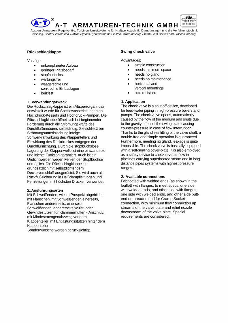
Rückschlagklappe Vorzüge:
• unkomplizierter Aufbau • geringer Platzbedarf • stopfbuchslos • wartungsfrei • waagerechte und
senkrechte Einbaulagen • beizfest
1. Verwendungszweck Die Rückschlagklappe ist ein Absperrorgan, das entwickelt wurde für Speisewasserleitungen an Hochdruck-Kesseln und Hochdruck-Pumpen. Die Rückschlagklappe öffnet sich bei beginnender Förderung durch die Strömungskräfte des Durchflußmediums selbständig. Sie schließt bei Strömungsunterbrechung infolge Schwerkraftwirkung des Klappentellers und Einwirkung des Rückdruckes entgegen der Durchflußrichtung. Durch die stopfbuchslose Lagerung der Klappenwelle ist eine einwandfreie und leichte Funktion garantiert. Auch ist ein Undichtwerden wegen Fehlen der Stopfbuchse unmöglich. Die Rückschlagklappe ist grundsätzlich mit selbstdichtendem Deckelverschluß ausgerüstet. Sie wird auch als Rückflußsicherung in Heißdampfleitungen und Fernleitungen mit höchsten Drucken verwendet. 2.. Ausführungsarten Mit Schweißenden, wie im Prospekt abgebildet, mit Flanschen, mit Schweißenden einerseits, Flanschen andererseits, einerseits Schweißenden, andererseits Wulst- oder Gewindestutzen für Klammermuffen - Anschluß, mit Mindestmengenabzweig vor dem Klappenteller, mit Entlastungsstutzen hinter dem Klappenteller, Sonderwünsche werden berücksichtigt.
Swing check valve Advantages:
• simple construction • needs minimum space • needs no gland • needs no maintenance • horizontal and
vertical mountings • acid resistant
1. Application The check valve is a shut off device, developed for feed-water piping in high-pressure boilers and pumps. The check valve opens, automatically caused by the flow of the medium and shuts due to the gravity effect of the swing plate causing counter-pressure in case of flow Interruption. Thanks to the glandless fitting of the valve shaft, a trouble-free and simple operation is guaranteed. Furthermore, needing no gland, leakage is quite impossible. The check valve is basically equipped with a self-sealing cover-plate. It is also employed as a safety device to check reverse-flow in pipelines carrying superheated steam and in long distance pipes systems with highest pressure ranges. 2. Available connections Fabricated with welded ends (as shown in the leaflet) with flanges, to meet specs, one side with welded ends, and other side with flanges, one side with welded ends, and other side butt-end or threaded end for Cramp Socket-connection, with minimum flow connection up streams of the valve plate and relief nozzle downstream of the valve plate. Special requirements are considered.

A-T ARMATUREN-TECHNIK GMBH Absperr-Armaturen, Regelventile, Turbinen-Umleitsysteme für Kraftwerkstechnik, Dampfanlagen und die Verfahrenstechnik
Isolating, Control Valves and Turbine Bypass Systems for the Electric Power Industry, Steam Plant Utilities and Process Industry
®
3. Aufbau und Wirkungsweise Das Gehäuse der Rückschlagklappe ist aus einem Schmiedestahlblock gearbeitet Die Wandstärke ist entsprechend Druck und Temperatur bis 650 °C bemessen. Der den Rückstrom absperrende Teller ist mit geringem axialem und radialem Spiel im Klappenhebel gelagert und mit Mutter gehalten. Der Klappenhebel wiederum kann um die Welle frei schwenken. Die Lagerung der beweglichen Teile in der Lagerplatte wird getrennt von den Abdichtorganen durchgeführt. Die Schraube wird nach dem Anziehen gesichert und drückt die Platte fest gegen den vierteiligen Sprengring, welcher dadurch gegen herausgleiten gesichert ist. Der Zylinderstift verhindert ein seitliches Verdrehen der Lagerplatte. Die Abdichtung des Gehäuses erfolgt durch einen selbstdichtenden Deckelverschluß. Durch die Konstruktion ist gewährleistet, daß der Klappenteller schon in drucklosem Zustand fest auf dem Sitz aufliegt, auch im waagerechten Einbau. Die Rückschlagklappe kann in waagerechte und senkrechte Leitungen eingebaut werden, wobei bei senkrechtem Einbau zu beachten ist, daß die Durchströmung von unten nach oben erfolgt. Das Einschweißen der Armatur und Glühen der Nähte kann ohne Demontage der Innenteile erfolgen. Ohne Gefährdung der Innenteile können unsere Rückschlagklappen gebeizt werden.
3. Construction and Operation The Check-Valve casing is fabricated out of solid forged steel piece. The wall thickness is designed for maximum pressure rating and temperature up to 650°C. The Swing check to stop reverse-flow is mounted in the disc-lever with little axial and radial play and held by screw nuts. The disc-lever can turn freely round the shaft. The movable parts of the disc are fitted separately from the sealing parts. After tightening, the screw is secured and presses the disc firmly against the four-parted thrust ring thus protecting against slipping. The cylindrical pin prevents a horizontal displacement of disc. The casing is provided with a self-sealing cover-plate. This construction guarantees that the valve disc fits firmly even when no pressure is acting, also in a horizontal and vertical position, where as in vertical Installation it must be made certain that the flow is in the direction from bottom to top. The welding of the valve and heat treatment of the seams may be carried out without removing the internals. The Check Valves may be pickled without harming the internals.

A-T ARMATUREN-TECHNIK GMBH Absperr-Armaturen, Regelventile, Turbinen-Umleitsysteme für Kraftwerkstechnik, Dampfanlagen und die Verfahrenstechnik
Isolating, Control Valves and Turbine Bypass Systems for the Electric Power Industry, Steam Plant Utilities and Process Industry
®
Rückschlagklappe Typ RK1 Schmiedestahl DN 50 bis 400 PN 63 Swing check valve type RK1 forged steel DN 50 to 400 PN 63
Abmessungen und Massen / Dimensions and weights Baulängen Face-to-face dimensions Flanscharmaturen in Anlehnung an: DIN 3202, Teil 1 Flanged ends as per similar to: DIN 3202, part 1 Einschweißarmaturen in Anlehnung an: DIN 3202, Teil 2 End-to-end dimension as per similar to: DIN 3202, part 2 Flansche, Abmessungen: DIN 2501, PN 63 Flanges, Dimensions as per: DIN 2501, PN 63 Schweißfugen: DIN 2559, Teil 1 Welding grooves: DIN 2559, part 1
Baumaße / Dimensions Masse Weight
Reihe DN L h1 h3 D b Ca. (kg)
50 250 174 357 180 26 40 65 290 195 420 205 26 50 80 310 216 483 215 28 60 100 350 237 546 250 30 85 125 400 273 630 295 34 110
1 150 450 326 725 345 36 170 175 500 357 819 375 40 230 200 550 389 914 415 42 280 225 600 420 1008 - - 360 250 650 462 1103 470 46 450 275 700 504 1208 - - 670 300 750 557 1313 530 52 850 350 850 620 1470 600 56 1100 400 950 693 1628 670 60 1200
Änderungen vobehalten / Th right is reserved to change specification without notice Größere Nennweiten, höhere Drücke und Baulängen nach DIN oder ANSI auf Anfrage Bigger diameters nominal, higher pressure and dimensions to DIN or ANSI on request

A-T ARMATUREN-TECHNIK GMBH Absperr-Armaturen, Regelventile, Turbinen-Umleitsysteme für Kraftwerkstechnik, Dampfanlagen und die Verfahrenstechnik
Isolating, Control Valves and Turbine Bypass Systems for the Electric Power Industry, Steam Plant Utilities and Process Industry
®
Werkstoffe / Materials
Pos. Nr. Bauteil -10°C bis / to 400°C -10°C bis / to 500°C Item No Component Werkstoff
MaterialStoff - Nr.
Material-No.Werkstoff Material
Stoff - Nr. Material-No.
1.1 Gehäuse / Body C22.8 1.0460 15MO3 1.5415 1.2 Gehäusekopf / Body C22.8 1.0460 15MO3 1.5415 1.3 Sitzring / Seat ring C22.8 / Stellit 1.0460 15MO3 / Stellit 1.5415 2 Gehäuseverschluß / seal bonnet C22.8 1.0460 15MO3 1.5415 5 Druckring / Thrust ring C22.8 1.0460 15MO3 1.5415 6 4tlg. Ring / Segmental thrust ring C22.8 1.0460 15MO3 1.5415 7 Deckel / Cover C22.8 1.0460 15MO3 1.5415 9 Lagerwelle / Pivo shaft X20CrNi17 2 1.4057 X20CrMoV12 1 1.4922 10 Lager / Bushing Alloy - Alloy - 11 Klappenteller / Disc C22.8 / Stellit 1.0460 15MO3 / Stellit 1.5415 11.1 Bolzen / Bolt C22.8 1.0460 15MO3 1.5415 12 Klappenhebel / Hanger C22.8 1.0460 15MO3 1.5415 13 Packungsring / Packing ring Grafit / 1.4541 - Grafit / 1.4541 - 14 Schraubenbolzen / Stud bolt 21CrMoV5 7 1:7709 21CrMoV5 7 1:7709 15 Skt.-Mutter / Heagon Nut 24CrMo5 1.7258 24CrMo5 1.7258
Pos. Nr. Bauteil -10°C bis / to 550°C -10°C bis / to 550°C Item No. Component Werkstoff
MaterialStoff - Nr.
Material-No.Werkstoff Material
Stoff - Nr. Material-No.
1.1 Gehäuse / Body 13CrMo4 4 1.7335 10CrMo9 10 1.7380 1.2 Gehäusekopf / Body 13CrMo4 4 1.7335 10CrMo9 10 1.7380 1.3 Sitzring / Seat ring 13CrMo4 4/Stellit 1.7335 10CrMo9 10/Stellit 1.7380 2 Gehäuseverschluß / seal bonnet 13CrMo4 4 1.7335 10CrMo9 10 1.7380 5 Druckring / Thrust ring 13CrMo4 4 1.7335 10CrMo9 10 1.7380 6 4tlg. Ring / Segmental thrust ring 13CrMo4 4 1.7335 10CrMo9 10 1.7380 7 Deckel / Cover 13CrMo4 4 1.7335 10CrMo9 10 1.7380 9 Lagerwelle / Pivo shaft X20CrMoV12 1 1.4922 X20CrMoV12 1 1.4922 10 Lager / Bushing Alloy - Alloy - 11 Klappenteller / Disc 13CrMo4 4/Stellit 1.7335 10CrMo9 10/Stellit 1.7380 11.1 Bolzen / Bolt 13CrMo4 4 1.7335 10CrMo9 10 1.7380 12 Klappenhebel / Hanger 13CrMo4 4 1.7335 10CrMo9 10 1.7380 13 Packungsring / Packing ring Grafit / 1.4541 - Grafit / 1.4541 - 14 Schraubenbolzen / Stud bolt 21CrMoV5 7 1:7709 21CrMoV5 7 1:7709 15 Skt.-Mutter / Heagon Nut 24CrMo5 1.7258 24CrMo5 1.7258
Weitere Werkstoffe auf Anfrage / Further materials on request Druck-Temperatur-Zuordnung / Pressure-Temperature-Rating Siehe Kennblatt / See technical data sheet Einsatzbereiche / Application Für nichtaggressive und aggressive Flüssigkeiten und Gase / For non - corrosive and corrosive liquids and gases Anfrage und Bestellung / Orders and inquiries Bei Anfrage und Bestellung werden benötigt: Nenndruck, Nennweite, Gehäusewerkstoff, maximale Betriebstemperatur, maximaler Betriebsdruck, Rohranschlußmaße für Einschweißenden, Betriebsmedium, Prüf- und Abnahmebedingungen sowie Art des Abnahmezeugnisses mach DIN50049 / EN 10204 und kundenspezifische Wünsche. Following data ar requiered for request and order: nominal pressure, nominal diameter, body material, maximum operating temperature, maximum operating pressure, pipe connection dimensions for butt - welding ends, operating medium, test and acceptance conditions, kind of acceptance certificate to DIN 50049 / EN 10204 and other customer - specific wishes. Prüfung und Abnahme / testing and acceptance Für die Prüfung und Abnahme gelten die Vorschriften nach DIN 3230 sowie kundenspecifische Vereinbarungen. The regulation in DIN 3230 and specific agreements with customer shall form the basis for testing and acceptance.

A-T ARMATUREN-TECHNIK GMBH Absperr-Armaturen, Regelventile, Turbinen-Umleitsysteme für Kraftwerkstechnik, Dampfanlagen und die Verfahrenstechnik
Isolating, Control Valves and Turbine Bypass Systems for the Electric Power Industry, Steam Plant Utilities and Process Industry
®
Rückschlagklappe Typ RK2 Schmiedestahl DN 50 bis 450 PN 100 Swing check valve type RK2 forged steel DN 50 to 450 PN 100
Abmessungen und Massen / Dimensions and weights Baulängen Face-to-face dimensions Flanscharmaturen in Anlehnung an: DIN 3202, Teil 1 Flanged ends as per similar to: DIN 3202, part 1 Einschweißarmaturen in Anlehnung an: DIN 3202, Teil 2 End-to-end dimension as per similar to: DIN 3202, part 2 Flansche, Abmessungen: DIN 2501, PN 100 Flanges, Dimensions as per: DIN 2501, PN 100 Schweißfugen: DIN 2559, Teil 1 Welding grooves: DIN 2559, part 1
Baumaße / Dimensions Masse Weight
Reihe DN L h1 h3 D b ca. (kg)
50 250 174 357 195 28 40 65 290 195 420 220 30 50 80 310 216 483 230 32 60 100 350 237 546 265 36 85 125 400 273 630 315 40 110
2 150 450 326 725 355 44 170 175 500 357 819 385 48 230 200 550 389 914 430 52 280 225 600 420 1008 - - 360 250 650 462 1103 505 60 450 275 700 504 1208 - - 670 300 750 557 1313 585 68 850 350 850 620 1470 655 74 1100 400 950 693 1628 - - 1200 450 1050 777 1838 - - 1400
Änderungen vobehalten / Th right is reserved to change specification without notice Größere Nennweiten, höhere Drücke und Baulängen nach DIN oder ANSI auf Anfrage Bigger diameters nominal, higher pressure and dimensions DIN or ANSI on request

A-T ARMATUREN-TECHNIK GMBH Absperr-Armaturen, Regelventile, Turbinen-Umleitsysteme für Kraftwerkstechnik, Dampfanlagen und die Verfahrenstechnik
Isolating, Control Valves and Turbine Bypass Systems for the Electric Power Industry, Steam Plant Utilities and Process Industry
®
Werkstoffe / Materials
Pos. Nr. Bauteil -10°C bis / to 400°C -10°C bis / to 500°C Item No Component Werkstoff
MaterialStoff - Nr.
Material-No.Werkstoff Material
Stoff - Nr. Material-No.
1.1 Gehäuse / Body C22.8 1.0460 15MO3 1.5415 1.2 Gehäusekopf / Body C22.8 1.0460 15MO3 1.5415 1.3 Sitzring / Seat ring C22.8 / Stellit 1.0460 15MO3 / Stellit 1.5415 2 Gehäuseverschluß / seal bonnet C22.8 1.0460 15MO3 1.5415 5 Druckring / Thrust ring C22.8 1.0460 15MO3 1.5415 6 4tlg. Ring / Segmental thrust ring C22.8 1.0460 15MO3 1.5415 7 Deckel / Cover C22.8 1.0460 15MO3 1.5415 9 Lagerwelle / Pivo shaft X20CrNi17 2 1.4057 X20CrMoV12 1 1.4922 10 Lager / Bushing Alloy - Alloy - 11 Klappenteller / Disc C22.8 / Stellit 1.0460 15MO3 / Stellit 1.5415 11.1 Bolzen / Bolt C22.8 1.0460 15MO3 1.5415 12 Klappenhebel / Hanger C22.8 1.0460 15MO3 1.5415 13 Packungsring / Packing ring Grafit / 1.4541 - Grafit / 1.4541 - 14 Schraubenbolzen / Stud bolt 21CrMoV5 7 1:7709 21CrMoV5 7 1:7709 15 Skt.-Mutter / Heagon Nut 24CrMo5 1.7258 24CrMo5 1.7258
Pos. Nr. Bauteil -10°C bis / to 550°C -10°C bis / to 550°C Item No. Component Werkstoff
MaterialStoff - Nr.
Material-No.Werkstoff Material
Stoff - Nr. Material-No.
1.1 Gehäuse / Body 13CrMo4 4 1.7335 10CrMo9 10 1.7380 1.2 Gehäusekopf / Body 13CrMo4 4 1.7335 10CrMo9 10 1.7380 1.3 Sitzring / Seat ring 13CrMo4 4/Stellit 1.7335 10CrMo9 10/Stellit 1.7380 2 Gehäuseverschluß / seal bonnet 13CrMo4 4 1.7335 10CrMo9 10 1.7380 5 Druckring / Thrust ring 13CrMo4 4 1.7335 10CrMo9 10 1.7380 6 4tlg. Ring / Segmental thrust ring 13CrMo4 4 1.7335 10CrMo9 10 1.7380 7 Deckel / Cover 13CrMo4 4 1.7335 10CrMo9 10 1.7380 9 Lagerwelle / Pivo shaft X20CrMoV12 1 1.4922 X20CrMoV12 1 1.4922 10 Lager / Bushing Alloy - Alloy - 11 Klappenteller / Disc 13CrMo4 4/Stellit 1.7335 10CrMo9 10/Stellit 1.7380 11.1 Bolzen / Bolt 13CrMo4 4 1.7335 10CrMo9 10 1.7380 12 Klappenhebel / Hanger 13CrMo4 4 1.7335 10CrMo9 10 1.7380 13 Packungsring / Packing ring Grafit / 1.4541 - Grafit / 1.4541 - 14 Schraubenbolzen / Stud bolt 21CrMoV5 7 1:7709 21CrMoV5 7 1:7709 15 Skt.-Mutter / Heagon Nut 24CrMo5 1.7258 24CrMo5 1.7258
Weitere Werkstoffe auf Anfrage / Further materials on request Druck-Temperatur-Zuordnung / Pressure-Temperature-Rating Siehe Kennblatt / See technical data sheet Einsatzbereiche / Application Für nichtaggressive und aggressive Flüssigkeiten und Gase / For non - corrosive and corrosive liquids and gases Anfrage und Bestellung / Orders and inquiries Bei Anfrage und Bestellung werden benötigt: Nenndruck, Nennweite, Gehäusewerkstoff, maximale Betriebstemperatur, maximaler Betriebsdruck, Rohranschlußmaße für Einschweißenden, Betriebsmedium, Prüf- und Abnahmebedingungen sowie Art des Abnahmezeugnisses mach DIN50049 / EN 10204 und kundenspezifische Wünsche. Following data ar requiered for request and order: nominal pressure, nominal diameter, body material, maximum operating temperature, maximum operating pressure, pipe connection dimensions for butt - welding ends, operating medium, test and acceptance conditions, kind of acceptance certificate to DIN 50049 / EN 10204 and other customer - specific wishes. Prüfung und Abnahme / testing and acceptance Für die Prüfung und Abnahme gelten die Vorschriften nach DIN 3230 sowie kundenspecifische Vereinbarungen. The regulation in DIN 3230 and specific agreements with customer shall form the basis for testing and acceptance.

A-T ARMATUREN-TECHNIK GMBH Absperr-Armaturen, Regelventile, Turbinen-Umleitsysteme für Kraftwerkstechnik, Dampfanlagen und die Verfahrenstechnik
Isolating, Control Valves and Turbine Bypass Systems for the Electric Power Industry, Steam Plant Utilities and Process Industry
®
Rückschlagklappe Schmiedestahl Typ RK3 DN 50 bis 450 PN 160 Swing check forged steel type RK3 DN 50 to 450 PN 160
Abmessungen und Massen / Dimensions and weights Baulängen Face-to-face dimensions Flanscharmaturen in Anlehnung an: DIN 3202, Teil 1 Flanged ends as per similar to: DIN 3202, part 1 Einschweißarmaturen in Anlehnung an: DIN 3202, Teil 2 End-to-end dimension as per similar to: DIN 3202, part 2 Flansche, Abmessungen: DIN 2501, PN 160 Flanges, Dimensions as per: DIN 2501, PN 160 Schweißfugen: DIN 2559, Teil 1 Welding grooves: DIN 2559, part 1
Baumaße / Dimensions Masse Weight
Reihe DN L h1 h3 D b ca. (kg)
50 300 174 357 195 30 42 65 360 195 420 220 34 53 80 390 216 483 230 36 66 100 450 237 546 265 40 112 125 525 273 630 315 44 147
3 150 600 326 725 355 50 225 175 675 357 819 390 54 343 200 750 389 914 430 60 420 225 825 420 1008 - - 476 250 900 462 1103 515 68 560 275 975 504 1208 - - 730 300 1000 557 1313 585 78 870 350 1050 620 1470 - - 1368 400 1100 693 1628 - - 2100 450 1200 777 1838 - - 2150
Änderungen vobehalten / Rights reserved to change specification without notice Größere Nennweiten, höhere Drücke und Baulängen nach DIN oder ANSI auf Anfrage Bigger diameters nominal, higher pressure and dimensions DIN or ANSI on request
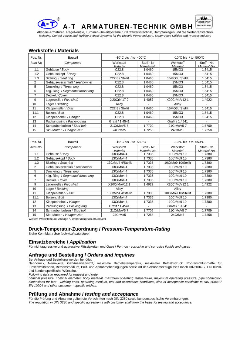
A-T ARMATUREN-TECHNIK GMBH Absperr-Armaturen, Regelventile, Turbinen-Umleitsysteme für Kraftwerkstechnik, Dampfanlagen und die Verfahrenstechnik
Isolating, Control Valves and Turbine Bypass Systems for the Electric Power Industry, Steam Plant Utilities and Process Industry
®
Werkstoffe / Materials
Pos. Nr. Bauteil -10°C bis / to 400°C -10°C bis / to 500°C Item No Component Werkstoff
MaterialStoff - Nr.
Material-No.Werkstoff Material
Stoff - Nr. Material-No.
1.1 Gehäuse / Body C22.8 1.0460 15MO3 1.5415 1.2 Gehäusekopf / Body C22.8 1.0460 15MO3 1.5415 1.3 Sitzring / Seat ring C22.8 / Stellit 1.0460 15MO3 / Stellit 1.5415 2 Gehäuseverschluß / seal bonnet C22.8 1.0460 15MO3 1.5415 5 Druckring / Thrust ring C22.8 1.0460 15MO3 1.5415 6 4tlg. Ring / Segmental thrust ring C22.8 1.0460 15MO3 1.5415 7 Deckel / Cover C22.8 1.0460 15MO3 1.5415 9 Lagerwelle / Pivo shaft X20CrNi17 2 1.4057 X20CrMoV12 1 1.4922 10 Lager / Bushing Alloy - Alloy - 11 Klappenteller / Disc C22.8 / Stellit 1.0460 15MO3 / Stellit 1.5415 11.1 Bolzen / Bolt C22.8 1.0460 15MO3 1.5415 12 Klappenhebel / Hanger C22.8 1.0460 15MO3 1.5415 13 Packungsring / Packing ring Grafit / 1.4541 - Grafit / 1.4541 - 14 Schraubenbolzen / Stud bolt 21CrMoV5 7 1:7709 21CrMoV5 7 1:7709 15 Skt.-Mutter / Heagon Nut 24CrMo5 1.7258 24CrMo5 1.7258
Pos. Nr. Bauteil -10°C bis / to 550°C -10°C bis / to 550°C Item No. Component Werkstoff
MaterialStoff - Nr.
Material-No.Werkstoff Material
Stoff - Nr. Material-No.
1.1 Gehäuse / Body 13CrMo4 4 1.7335 10CrMo9 10 1.7380 1.2 Gehäusekopf / Body 13CrMo4 4 1.7335 10CrMo9 10 1.7380 1.3 Sitzring / Seat ring 13CrMo4 4/Stellit 1.7335 10CrMo9 10/Stellit 1.7380 2 Gehäuseverschluß / seal bonnet 13CrMo4 4 1.7335 10CrMo9 10 1.7380 5 Druckring / Thrust ring 13CrMo4 4 1.7335 10CrMo9 10 1.7380 6 4tlg. Ring / Segmental thrust ring 13CrMo4 4 1.7335 10CrMo9 10 1.7380 7 Deckel / Cover 13CrMo4 4 1.7335 10CrMo9 10 1.7380 9 Lagerwelle / Pivo shaft X20CrMoV12 1 1.4922 X20CrMoV12 1 1.4922 10 Lager / Bushing Alloy - Alloy - 11 Klappenteller / Disc 13CrMo4 4/Stellit 1.7335 10CrMo9 10/Stellit 1.7380 11.1 Bolzen / Bolt 13CrMo4 4 1.7335 10CrMo9 10 1.7380 12 Klappenhebel / Hanger 13CrMo4 4 1.7335 10CrMo9 10 1.7380 13 Packungsring / Packing ring Grafit / 1.4541 - Grafit / 1.4541 - 14 Schraubenbolzen / Stud bolt 21CrMoV5 7 1:7709 21CrMoV5 7 1:7709 15 Skt.-Mutter / Heagon Nut 24CrMo5 1.7258 24CrMo5 1.7258
Weitere Werkstoffe auf Anfrage / Further materials on request Druck-Temperatur-Zuordnung / Pressure-Temperature-Rating Siehe Kennblatt / See technical data sheet Einsatzbereiche / Application Für nichtaggressive und aggressive Flüssigkeiten und Gase / For non - corrosive and corrosive liquids and gases Anfrage und Bestellung / Orders and inquiries Bei Anfrage und Bestellung werden benötigt: Nenndruck, Nennweite, Gehäusewerkstoff, maximale Betriebstemperatur, maximaler Betriebsdruck, Rohranschlußmaße für Einschweißenden, Betriebsmedium, Prüf- und Abnahmebedingungen sowie Art des Abnahmezeugnisses mach DIN50049 / EN 10204 und kundenspezifische Wünsche. Following data ar requiered for request and order: nominal pressure, nominal diameter, body material, maximum operating temperature, maximum operating pressure, pipe connection dimensions for butt - welding ends, operating medium, test and acceptance conditions, kind of acceptance certificate to DIN 50049 / EN 10204 and other customer - specific wishes. Prüfung und Abnahme / testing and acceptance Für die Prüfung und Abnahme gelten die Vorschriften nach DIN 3230 sowie kundenspecifische Vereinbarungen. The regulation in DIN 3230 and specific agreements with customer shall form the basis for testing and acceptance.

A-T ARMATUREN-TECHNIK GMBH Absperr-Armaturen, Regelventile, Turbinen-Umleitsysteme für Kraftwerkstechnik, Dampfanlagen und die Verfahrenstechnik
Isolating, Control Valves and Turbine Bypass Systems for the Electric Power Industry, Steam Plant Utilities and Process Industry
®
Rückschlagklappe Schmiedestahl Typ RK4 DN 50 bis 400 PN 250 Swing check forged steel valves type RK4 DN 50 to 400 PN 250
Abmessungen und Massen / Dimensions and weights Baulängen Face-to-face dimensions Flanscharmaturen in Anlehnung an: DIN 3202, Teil 1 Flanged ends as per similar to: DIN 3202, part 1 Einschweißarmaturen in Anlehnung an: DIN 3202, Teil 2 End-to-end dimension as per similar to: DIN 3202, part 2 Flansche, Abmessungen: DIN 2501, PN 250 Flanges, Dimensions as per: DIN 2501, PN 250 Schweißfugen: DIN 2559, Teil 1 Welding grooves: DIN 2559, part 1
Baumaße / Dimensions Masse Weight
Reihe DN L h1 h3 D b ca. (kg)
50 350 175 350 200 38 65 425 195 410 230 42 80 470 220 475 255 46 100 550 245 540 300 54 125 650 285 620 340 60
4 150 750 335 720 390 68 175 850 365 810 430 74 200 950 400 900 485 82 225 1050 430 990 - - 250 1150 460 1080 585 100 275 1250 520 1200 - - 300 1350 570 1300 - - 350 1400 620 1450 - - 400 1450 680 1600 - -
Änderungen vobehalten / Rights reserved to change specification without notice Größere Nennweiten, höhere Drücke und Baulängen nach DIN oder ANSI auf Anfrage Bigger diameters nominal, higher pressure and dimensions DIN or ANSI on request
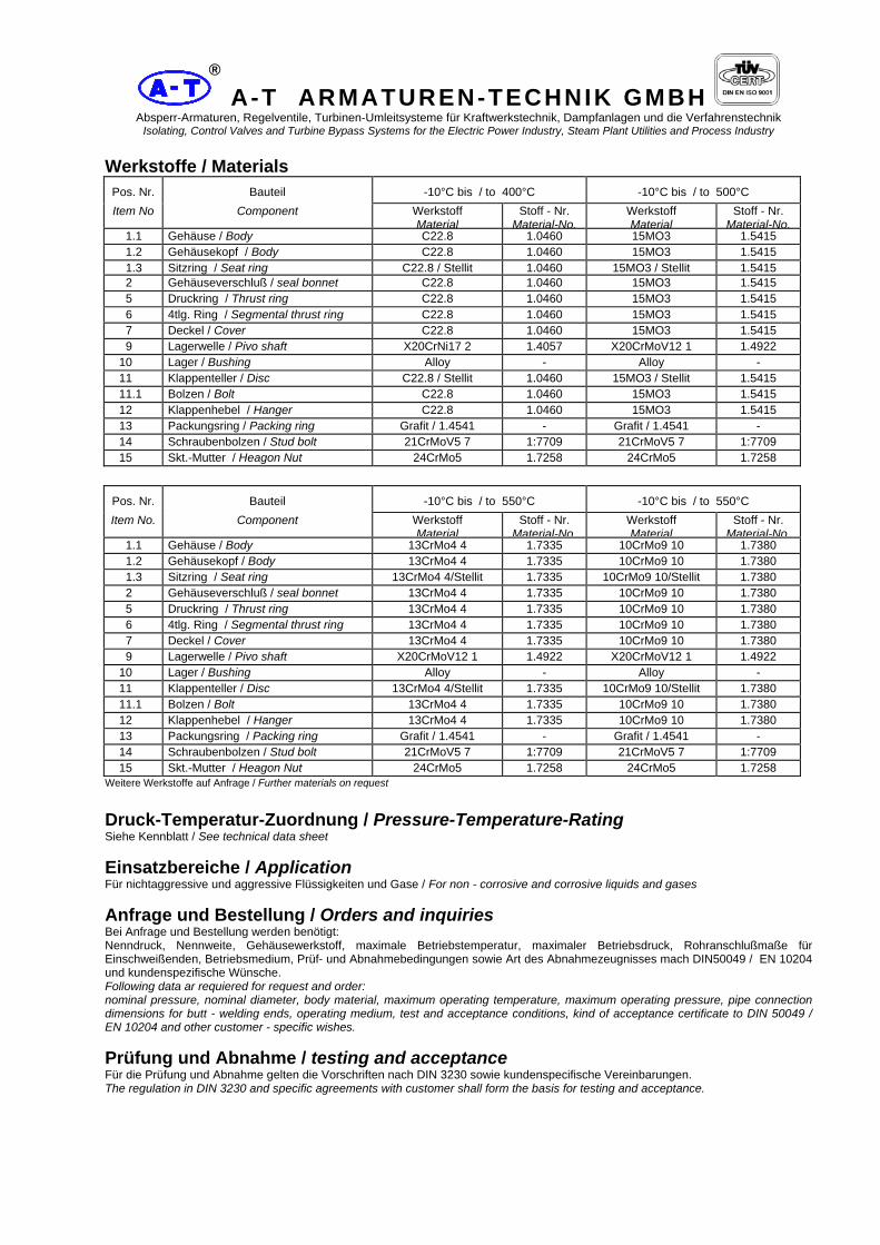
A-T ARMATUREN-TECHNIK GMBH Absperr-Armaturen, Regelventile, Turbinen-Umleitsysteme für Kraftwerkstechnik, Dampfanlagen und die Verfahrenstechnik
Isolating, Control Valves and Turbine Bypass Systems for the Electric Power Industry, Steam Plant Utilities and Process Industry
®
Werkstoffe / Materials Pos. Nr. Bauteil -10°C bis / to 400°C -10°C bis / to 500°C Item No Component Werkstoff
MaterialStoff - Nr.
Material-No.Werkstoff Material
Stoff - Nr. Material-No.
1.1 Gehäuse / Body C22.8 1.0460 15MO3 1.5415 1.2 Gehäusekopf / Body C22.8 1.0460 15MO3 1.5415 1.3 Sitzring / Seat ring C22.8 / Stellit 1.0460 15MO3 / Stellit 1.5415 2 Gehäuseverschluß / seal bonnet C22.8 1.0460 15MO3 1.5415 5 Druckring / Thrust ring C22.8 1.0460 15MO3 1.5415 6 4tlg. Ring / Segmental thrust ring C22.8 1.0460 15MO3 1.5415 7 Deckel / Cover C22.8 1.0460 15MO3 1.5415 9 Lagerwelle / Pivo shaft X20CrNi17 2 1.4057 X20CrMoV12 1 1.4922 10 Lager / Bushing Alloy - Alloy - 11 Klappenteller / Disc C22.8 / Stellit 1.0460 15MO3 / Stellit 1.5415 11.1 Bolzen / Bolt C22.8 1.0460 15MO3 1.5415 12 Klappenhebel / Hanger C22.8 1.0460 15MO3 1.5415 13 Packungsring / Packing ring Grafit / 1.4541 - Grafit / 1.4541 - 14 Schraubenbolzen / Stud bolt 21CrMoV5 7 1:7709 21CrMoV5 7 1:7709 15 Skt.-Mutter / Heagon Nut 24CrMo5 1.7258 24CrMo5 1.7258
Pos. Nr. Bauteil -10°C bis / to 550°C -10°C bis / to 550°C Item No. Component Werkstoff
MaterialStoff - Nr.
Material-No.Werkstoff Material
Stoff - Nr. Material-No.
1.1 Gehäuse / Body 13CrMo4 4 1.7335 10CrMo9 10 1.7380 1.2 Gehäusekopf / Body 13CrMo4 4 1.7335 10CrMo9 10 1.7380 1.3 Sitzring / Seat ring 13CrMo4 4/Stellit 1.7335 10CrMo9 10/Stellit 1.7380 2 Gehäuseverschluß / seal bonnet 13CrMo4 4 1.7335 10CrMo9 10 1.7380 5 Druckring / Thrust ring 13CrMo4 4 1.7335 10CrMo9 10 1.7380 6 4tlg. Ring / Segmental thrust ring 13CrMo4 4 1.7335 10CrMo9 10 1.7380 7 Deckel / Cover 13CrMo4 4 1.7335 10CrMo9 10 1.7380 9 Lagerwelle / Pivo shaft X20CrMoV12 1 1.4922 X20CrMoV12 1 1.4922 10 Lager / Bushing Alloy - Alloy - 11 Klappenteller / Disc 13CrMo4 4/Stellit 1.7335 10CrMo9 10/Stellit 1.7380 11.1 Bolzen / Bolt 13CrMo4 4 1.7335 10CrMo9 10 1.7380 12 Klappenhebel / Hanger 13CrMo4 4 1.7335 10CrMo9 10 1.7380 13 Packungsring / Packing ring Grafit / 1.4541 - Grafit / 1.4541 - 14 Schraubenbolzen / Stud bolt 21CrMoV5 7 1:7709 21CrMoV5 7 1:7709 15 Skt.-Mutter / Heagon Nut 24CrMo5 1.7258 24CrMo5 1.7258
Weitere Werkstoffe auf Anfrage / Further materials on request Druck-Temperatur-Zuordnung / Pressure-Temperature-Rating Siehe Kennblatt / See technical data sheet Einsatzbereiche / Application Für nichtaggressive und aggressive Flüssigkeiten und Gase / For non - corrosive and corrosive liquids and gases Anfrage und Bestellung / Orders and inquiries Bei Anfrage und Bestellung werden benötigt: Nenndruck, Nennweite, Gehäusewerkstoff, maximale Betriebstemperatur, maximaler Betriebsdruck, Rohranschlußmaße für Einschweißenden, Betriebsmedium, Prüf- und Abnahmebedingungen sowie Art des Abnahmezeugnisses mach DIN50049 / EN 10204 und kundenspezifische Wünsche. Following data ar requiered for request and order: nominal pressure, nominal diameter, body material, maximum operating temperature, maximum operating pressure, pipe connection dimensions for butt - welding ends, operating medium, test and acceptance conditions, kind of acceptance certificate to DIN 50049 / EN 10204 and other customer - specific wishes. Prüfung und Abnahme / testing and acceptance Für die Prüfung und Abnahme gelten die Vorschriften nach DIN 3230 sowie kundenspecifische Vereinbarungen. The regulation in DIN 3230 and specific agreements with customer shall form the basis for testing and acceptance.

A-T ARMATUREN-TECHNIK GMBH Absperr-Armaturen, Regelventile, Turbinen-Umleitsysteme für Kraftwerkstechnik, Dampfanlagen und die Verfahrenstechnik
Isolating, Control Valves and Turbine Bypass Systems for the Electric Power Industry, Steam Plant Utilities and Process Industry
®
Rückschlagklappe Schmiedestahl Typ RK5 DN 50 bis 400 PN 320 Swing check forged steel valves type RK5 DN 50 to 400 PN 320
Abmessungen und Massen / Dimensions and weights Baulängen Face-to-face dimensions Flanscharmaturen in Anlehnung an: DIN 3202, Teil 1 Flanged ends as per similar to: DIN 3202, part 1 Einschweißarmaturen in Anlehnung an: DIN 3202, Teil 2 End-to-end dimension as per similar to: DIN 3202, part 2 Flansche, Abmessungen: DIN 2501, PN 320 Flanges, Dimensions as per: DIN 2501, PN 320 Schweißfugen: DIN 2559, Teil 1 Welding grooves: DIN 2559, part 1
Baumaße / Dimensions Masse Weight
Reihe DN L h1 h3 D b ca. (kg)
50 350 175 350 210 42 65 425 195 410 255 51 80 470 220 475 275 55 100 550 245 540 335 65 125 650 285 620 380 75
5 150 750 335 720 425 84 175 850 365 810 485 95 200 950 400 900 525 103 225 1050 430 990 - - 250 1150 460 1080 640 125 275 1250 520 1200 - - 300 1350 570 1300 - - 350 1500 620 1450 - - 400 1600 680 1600 - -
Änderungen vobehalten / Right is reserved to change specification without notice Größere Nennweiten, höhere Drücke und Baulängen nach DIN oder ANSI auf Anfrage Bigger diameters nominal, higher pressure and dimensions DIN or ANSI on request

A-T ARMATUREN-TECHNIK GMBH Absperr-Armaturen, Regelventile, Turbinen-Umleitsysteme für Kraftwerkstechnik, Dampfanlagen und die Verfahrenstechnik
Isolating, Control Valves and Turbine Bypass Systems for the Electric Power Industry, Steam Plant Utilities and Process Industry
®
Werkstoffe / Materials Pos. Nr. Bauteil -10°C bis / to 400°C -10°C bis / to 500°C Item No Component Werkstoff
MaterialStoff - Nr.
Material-No.Werkstoff Material
Stoff - Nr. Material-No.
1.1 Gehäuse / Body C22.8 1.0460 15MO3 1.5415 1.2 Gehäusekopf / Body C22.8 1.0460 15MO3 1.5415 1.3 Sitzring / Seat ring C22.8 / Stellit 1.0460 15MO3 / Stellit 1.5415 2 Gehäuseverschluß / seal bonnet C22.8 1.0460 15MO3 1.5415 5 Druckring / Thrust ring C22.8 1.0460 15MO3 1.5415 6 4tlg. Ring / Segmental thrust ring C22.8 1.0460 15MO3 1.5415 7 Deckel / Cover C22.8 1.0460 15MO3 1.5415 9 Lagerwelle / Pivo shaft X20CrNi17 2 1.4057 X20CrMoV12 1 1.4922 10 Lager / Bushing Alloy - Alloy - 11 Klappenteller / Disc C22.8 / Stellit 1.0460 15MO3 / Stellit 1.5415 11.1 Bolzen / Bolt C22.8 1.0460 15MO3 1.5415 12 Klappenhebel / Hanger C22.8 1.0460 15MO3 1.5415 13 Packungsring / Packing ring Grafit / 1.4541 - Grafit / 1.4541 - 14 Schraubenbolzen / Stud bolt 21CrMoV5 7 1:7709 21CrMoV5 7 1:7709 15 Skt.-Mutter / Heagon Nut 24CrMo5 1.7258 24CrMo5 1.7258
Pos. Nr. Bauteil -10°C bis / to 550°C -10°C bis / to 550°C Item No. Component Werkstoff
MaterialStoff - Nr.
Material-No.Werkstoff Material
Stoff - Nr. Material-No.
1.1 Gehäuse / Body 13CrMo4 4 1.7335 10CrMo9 10 1.7380 1.2 Gehäusekopf / Body 13CrMo4 4 1.7335 10CrMo9 10 1.7380 1.3 Sitzring / Seat ring 13CrMo4 4/Stellit 1.7335 10CrMo9 10/Stellit 1.7380 2 Gehäuseverschluß / seal bonnet 13CrMo4 4 1.7335 10CrMo9 10 1.7380 5 Druckring / Thrust ring 13CrMo4 4 1.7335 10CrMo9 10 1.7380 6 4tlg. Ring / Segmental thrust ring 13CrMo4 4 1.7335 10CrMo9 10 1.7380 7 Deckel / Cover 13CrMo4 4 1.7335 10CrMo9 10 1.7380 9 Lagerwelle / Pivo shaft X20CrMoV12 1 1.4922 X20CrMoV12 1 1.4922 10 Lager / Bushing Alloy - Alloy - 11 Klappenteller / Disc 13CrMo4 4/Stellit 1.7335 10CrMo9 10/Stellit 1.7380 11.1 Bolzen / Bolt 13CrMo4 4 1.7335 10CrMo9 10 1.7380 12 Klappenhebel / Hanger 13CrMo4 4 1.7335 10CrMo9 10 1.7380 13 Packungsring / Packing ring Grafit / 1.4541 - Grafit / 1.4541 - 14 Schraubenbolzen / Stud bolt 21CrMoV5 7 1:7709 21CrMoV5 7 1:7709 15 Skt.-Mutter / Heagon Nut 24CrMo5 1.7258 24CrMo5 1.7258
Weitere Werkstoffe auf Anfrage / Further materials on request Druck-Temperatur-Zuordnung / Pressure-Temperature-Rating Siehe Kennblatt / See technical data sheet Einsatzbereiche / Application Für nichtaggressive und aggressive Flüssigkeiten und Gase / For non - corrosive and corrosive liquids and gases Anfrage und Bestellung / Orders and inquiries Bei Anfrage und Bestellung werden benötigt: Nenndruck, Nennweite, Gehäusewerkstoff, maximale Betriebstemperatur, maximaler Betriebsdruck, Rohranschlußmaße für Einschweißenden, Betriebsmedium, Prüf- und Abnahmebedingungen sowie Art des Abnahmezeugnisses mach DIN50049 / EN 10204 und kundenspezifische Wünsche. Following data ar requiered for request and order: nominal pressure, nominal diameter, body material, maximum operating temperature, maximum operating pressure, pipe connection dimensions for butt - welding ends, operating medium, test and acceptance conditions, kind of acceptance certificate to DIN 50049 / EN 10204 and other customer - specific wishes. Prüfung und Abnahme / testing and acceptance Für die Prüfung und Abnahme gelten die Vorschriften nach DIN 3230 sowie kundenspecifische Vereinbarungen. The regulation in DIN 3230 and specific agreements with customer shall form the basis for testing and acceptance.

A-T ARMATUREN-TECHNIK GMBH Absperr-Armaturen, Regelventile, Turbinen-Umleitsysteme für Kraftwerkstechnik, Dampfanlagen und die Verfahrenstechnik
Isolating, Control Valves and Turbine Bypass Systems for the Electric Power Industry, Steam Plant Utilities and Process Industry
®
Rückschlagklappe Schmiedestahl Typ RK6 DN 50 bis 350 PN 400 Swing check forged steel valves type RK6 DN 50 to 350 PN 400
Abmessungen und Massen / Dimensions and weights Baulängen Face-to-face dimensions Flanscharmaturen in Anlehnung an: DIN 3202, Teil 1 Flanged ends as per similar to: DIN 3202, part 1 Einschweißarmaturen in Anlehnung an: DIN 3202, Teil 2 End-to-end dimension as per similar to: DIN 3202, part 2 Flansche, Abmessungen: DIN 2501, PN 400 Flanges, Dimensions as per: DIN 2501, PN 400 Schweißfugen: DIN 2559, Teil 1 Welding grooves: DIN 2559, part 1
Baumaße / Dimensions Masse Weight
Reihe DN L h1 h3 D b ca. (kg)
50 350 185 360 235 52 65 425 205 420 290 64 80 470 230 485 305 68 100 550 255 550 370 80 125 650 295 630 415 92
6 150 750 350 735 475 105 175 850 380 830 - - 200 950 420 920 585 130 225 1050 450 1010 - - 250 1150 480 1100 - - 275 1250 540 1220 - - 300 1350 600 1330 - - 350 1500 650 1480 - -
Änderungen vobehalten / Rights reserved to change specification without notice Größere Nennweiten, höhere Drücke und Baulängen nach DIN oder ANSI auf Anfrage Bigger diameters nominal, higher pressure and dimensions DIN or ANSI on request

A-T ARMATUREN-TECHNIK GMBH Absperr-Armaturen, Regelventile, Turbinen-Umleitsysteme für Kraftwerkstechnik, Dampfanlagen und die Verfahrenstechnik
Isolating, Control Valves and Turbine Bypass Systems for the Electric Power Industry, Steam Plant Utilities and Process Industry
®
Werkstoffe / Materials Pos. Nr. Bauteil -10°C bis / to 400°C -10°C bis / to 500°C Item No Component Werkstoff
MaterialStoff - Nr.
Material-No.Werkstoff Material
Stoff - Nr. Material-No.
1.1 Gehäuse / Body C22.8 1.0460 15MO3 1.5415 1.2 Gehäusekopf / Body C22.8 1.0460 15MO3 1.5415 1.3 Sitzring / Seat ring C22.8 / Stellit 1.0460 15MO3 / Stellit 1.5415 2 Gehäuseverschluß / seal bonnet C22.8 1.0460 15MO3 1.5415 5 Druckring / Thrust ring C22.8 1.0460 15MO3 1.5415 6 4tlg. Ring / Segmental thrust ring C22.8 1.0460 15MO3 1.5415 7 Deckel / Cover C22.8 1.0460 15MO3 1.5415 9 Lagerwelle / Pivo shaft X20CrNi17 2 1.4057 X20CrMoV12 1 1.4922 10 Lager / Bushing Alloy - Alloy - 11 Klappenteller / Disc C22.8 / Stellit 1.0460 15MO3 / Stellit 1.5415 11.1 Bolzen / Bolt C22.8 1.0460 15MO3 1.5415 12 Klappenhebel / Hanger C22.8 1.0460 15MO3 1.5415 13 Packungsring / Packing ring Grafit / 1.4541 - Grafit / 1.4541 - 14 Schraubenbolzen / Stud bolt 21CrMoV5 7 1:7709 21CrMoV5 7 1:7709 15 Skt.-Mutter / Heagon Nut 24CrMo5 1.7258 24CrMo5 1.7258
Pos. Nr. Bauteil -10°C bis / to 550°C -10°C bis / to 550°C Item No. Component Werkstoff
MaterialStoff - Nr.
Material-No.Werkstoff Material
Stoff - Nr. Material-No.
1.1 Gehäuse / Body 13CrMo4 4 1.7335 10CrMo9 10 1.7380 1.2 Gehäusekopf / Body 13CrMo4 4 1.7335 10CrMo9 10 1.7380 1.3 Sitzring / Seat ring 13CrMo4 4/Stellit 1.7335 10CrMo9 10/Stellit 1.7380 2 Gehäuseverschluß / seal bonnet 13CrMo4 4 1.7335 10CrMo9 10 1.7380 5 Druckring / Thrust ring 13CrMo4 4 1.7335 10CrMo9 10 1.7380 6 4tlg. Ring / Segmental thrust ring 13CrMo4 4 1.7335 10CrMo9 10 1.7380 7 Deckel / Cover 13CrMo4 4 1.7335 10CrMo9 10 1.7380 9 Lagerwelle / Pivo shaft X20CrMoV12 1 1.4922 X20CrMoV12 1 1.4922 10 Lager / Bushing Alloy - Alloy - 11 Klappenteller / Disc 13CrMo4 4/Stellit 1.7335 10CrMo9 10/Stellit 1.7380 11.1 Bolzen / Bolt 13CrMo4 4 1.7335 10CrMo9 10 1.7380 12 Klappenhebel / Hanger 13CrMo4 4 1.7335 10CrMo9 10 1.7380 13 Packungsring / Packing ring Grafit / 1.4541 - Grafit / 1.4541 - 14 Schraubenbolzen / Stud bolt 21CrMoV5 7 1:7709 21CrMoV5 7 1:7709 15 Skt.-Mutter / Heagon Nut 24CrMo5 1.7258 24CrMo5 1.7258
Weitere Werkstoffe auf Anfrage / Further materials on request Druck-Temperatur-Zuordnung / Pressure-Temperature-Rating Siehe Kennblatt / See technical data sheet Einsatzbereiche / Application Für nichtaggressive und aggressive Flüssigkeiten und Gase / For non - corrosive and corrosive liquids and gases Anfrage und Bestellung / Orders and inquiries Bei Anfrage und Bestellung werden benötigt: Nenndruck, Nennweite, Gehäusewerkstoff, maximale Betriebstemperatur, maximaler Betriebsdruck, Rohranschlußmaße für Einschweißenden, Betriebsmedium, Prüf- und Abnahmebedingungen sowie Art des Abnahmezeugnisses mach DIN50049 / EN 10204 und kundenspezifische Wünsche. Following data ar requiered for request and order: nominal pressure, nominal diameter, body material, maximum operating temperature, maximum operating pressure, pipe connection dimensions for butt - welding ends, operating medium, test and acceptance conditions, kind of acceptance certificate to DIN 50049 / EN 10204 and other customer - specific wishes. Prüfung und Abnahme / testing and acceptance Für die Prüfung und Abnahme gelten die Vorschriften nach DIN 3230 sowie kundenspecifische Vereinbarungen. The regulation in DIN 3230 and specific agreements with customer shall form the basis for testing and acceptance.

A-T ARMATUREN-TECHNIK GMBH Absperr-Armaturen, Regelventile, Turbinen-Umleitsysteme für Kraftwerkstechnik, Dampfanlagen und die Verfahrenstechnik
Isolating, Control Valves and Turbine Bypass Systems for the Electric Power Industry, Steam Plant Utilities and Process Industry
®
Einspritzwasser Regelventil ESV Spraywater control valve ESV
A-T Armaturen-Technik GmbH Babcock T-Bldg Tel.: +49 208 833 1700 E-Mail: [email protected] Duisburger Straße 375 46049 Oberhausen / Germany Fax: +49 208 833 1755 Web: www.at-armaturen.com
®

A-T ARMATUREN-TECHNIK GMBH Absperr-Armaturen, Regelventile, Turbinen-Umleitsysteme für Kraftwerkstechnik, Dampfanlagen und die Verfahrenstechnik
Isolating, Control Valves and Turbine Bypass Systems for the Electric Power Industry, Steam Plant Utilities and Process Industry
®
Vorzüge:
• unkomplizierter Aufbau • problemlose Austauschbarkeit
des Ventilsitzes • geringe Stellkräfte • wartungsarm • Betätigung durch alle üblichen
Antriebsarten • kostengünstig • kurze Lieferzeit
Verwendungszweck: Die Ventile dieser Baureihe haben die Aufgabe, das zur Heißdampf-Temperaturregelung dienende Einspritzwasser geregelt den nachgeschalteten Armaturen oder Kühlern zuzuführen. Um eine gute Anpassung der Armaturen an den vorliegenden Betriebsfall zu erreichen, sind die Einspritzventile in ein- oder mehrstufiger Ausführung lieferbar. Sie können jedoch auch als Regel- und Absperrventile für andere Medien verwendet werden. Aufbau und Wirkungsweise: Der grundsätzliche Aufbau der Ventile kann dem nebenstehenden Schnittbild entnommen werden, welches ein Ventil in Einstufenausführung zeigt. Für Sonderfälle, d.h. sehr hohe Druckgefälle, ist die Armatur mit mehrstufigem Sitz/Kegel lieferbar. Das nachfolgende Schnittbild zeigt die Konstruktion eines vierstufigen Ventils.
Advantages:
• simple design • easy exchaneability of valve seat • low actuating force • low maintenance efforts • actuated by any common drive types • cost - effective • short delivery period
Application Range: Valves of this series feed injection water in a controlled way to the connected fittings and/or coolers. The injection water serves as a hot-steam temperature control. To achieve a good adaptation for each application, the injection valves are available as singlestage or multistage type. However, they can be used as control or stop valves also for other media. Design and Function: A principle of the valve design is shown in the sketch to the right (singlestage valve type). In the case of special applications, i.e. very high pressure differences, the valve is available as a multistage seat/cone version. The sketch below shows the design of a four-stage valve.

A-T ARMATUREN-TECHNIK GMBH Absperr-Armaturen, Regelventile, Turbinen-Umleitsysteme für Kraftwerkstechnik, Dampfanlagen und die Verfahrenstechnik
Isolating, Control Valves and Turbine Bypass Systems for the Electric Power Industry, Steam Plant Utilities and Process Industry
®
Hervorzuheben sind die stabile, gesenkgeschmiedete Ausführung des Ventilgehäuses, die verschleißfeste Konstruktion von Sitz und Kegel sowie die reibungsarme, nachziehbare Spindelabdichtung. Diese besteht, wie die Gehäusedichtung, aus Reingrafit. Gehäuse -und Sitzdichtung bilden gemeinsam eine im Krafthauptschluss liegende statische Doppeldichtung. Ventilkegel und -sitz werden im Werk dichtschließend eingeschliffen. Während des Betriebes werden diese Teile durch den am Gehäuseverschluss befindlichen Lochzylinder vor groben Fremdkörpern geschützt. Um auch feinere Verunreinigungen fernzuhalten, empfehlen wir den Einbau eines separaten Schmutzabscheiders vor der Armatur.
Einstufiges Ventil One stage valve
The stable and drop-forged design of the valve casing, the wear-resistant construction of seat and cone, as well the low-friction spindle sealing which can be readjusted are features to be underlined. Together with the casing seal, also the spindle seal consists of pure graphite. Casing and seat seal form a static double sealing which is positioned in the line of the main power direction. Valve cone and seat are ground-in sealed during manufacturing. During operation, these parts are protected against coarsely foreign particles by a perforated cylinder which is installed in the casing cover. To protect the unit against fine particles, we recommend installing a particle separator upstreams.
Mehrstufiges Ventil Multistage valve

A-T ARMATUREN-TECHNIK GMBH Absperr-Armaturen, Regelventile, Turbinen-Umleitsysteme für Kraftwerkstechnik, Dampfanlagen und die Verfahrenstechnik
Isolating, Control Valves and Turbine Bypass Systems for the Electric Power Industry, Steam Plant Utilities and Process Industry
®
Technische Daten:
Gehäuse: Eck-, Z- oder Durchgangsform
Nennweite: 15-125 mm
Druckstufen: bis PN 400
Zulässige Druckgefälle: Alle üblichen Druckgefälle, bei hohen Druckdifferenzen in mehrstufiger Ausführung
Packungen: Nachziehbare Reingrafit- Spindel-Abdichtung, Gehäuse und Sitz-Dichtung ebenfalls aus Reingrafit
Anschlüsse: Wahlweise Anschweißenden oder Flanschanschluss
Werkstoffe: Gehäuse:1.5415 1.4057 Sitz: 1.4057 Spindel: 1.4922/1.4903
Abweichend von den beschriebenen Armaturenausführungen sind die Ventile auch in anderen Werkstoffen ausführbar, für andere Medien und Einsatzbereiche verwendbar.
Antriebe: Pneumatisch. Hydraulisch, elektrisch über Dreh- oder Hebelantrieb, Handrad
Technical Data Casing shape: Elbow, Z, or straight
shape Nominal diameter: 15 – 125 mm Pressure level: up to PN 400 Permissible pressure difference: all commonly used pressure differences, high pressure differences with multistage valve type Gland packings: readjustable pure graphite spindle sealing, seal for casing and seat also made of pure graphite Connections: optionally butt-weld ends or flange connection Materials: casing: 1.5415, 1.4057
seat: 1.4057 spindle:1.4922/1.4903
In addition to the fitting types described above, the valves can be made of other materials and can be used for other media and different applications. Actuator: pneumatically, hydraulically, electrically with use of rotary or lever drive, handwheel

A-T ARMATUREN-TECHNIK GMBH Absperr-Armaturen, Regelventile, Turbinen-Umleitsysteme für Kraftwerkstechnik, Dampfanlagen und die Verfahrenstechnik
Isolating, Control Valves and Turbine Bypass Systems for the Electric Power Industry, Steam Plant Utilities and Process Industry
®
Baugröße Pressure stage
I (bis PN 400) I (up to PN400)
II (bis PN 400) II (up to PN400)
III (bis PN 400) III (up to PN 400)
Nennweiten Nominal diameter
DN 15-50 25-80 65-125
Kvs [m³/h] Kvs [m³/h]
max. 11 Max. 25 max.72
Kennlinie Characteristic
Gleichprozentig, (auf Wunsch linear oder Quadratisch)
Sitzdurchmesser mm Seat diameter mm
max. 18 Max. 30 max.50
Spindeldurchmesser Spindlediameter mm
16 24 35
Hub mm Stroke mm
20 25 35

A-T ARMATUREN-TECHNIK GMBH Absperr-Armaturen, Regelventile, Turbinen-Umleitsysteme für Kraftwerkstechnik, Dampfanlagen und die Verfahrenstechnik
Isolating, Control Valves and Turbine Bypass Systems for the Electric Power Industry, Steam Plant Utilities and Process Industry
®
Mindestmengenventil Minimum flow control valve
A-T Armaturen-Technik GmbH Babcock T-Bldg Tel.: +49 208 833 1700 E-Mail: [email protected] Duisburger Straße 375 46049 Oberhausen / Germany Fax: +49 208 833 1755 Web: www.at-armaturen.com
®

A-T ARMATUREN-TECHNIK GMBH Absperr-Armaturen, Regelventile, Turbinen-Umleitsysteme für Kraftwerkstechnik, Dampfanlagen und die Verfahrenstechnik, Öl- und Gas Pipelines
Isolating, Control Valves and Turbine Bypass Systems for the Electric Power Industry, Steam Plant Utilities and Process Industry, oil and gas pipelines
59
®
1. Verwendungszweck Bei in Betrieb befindlichen Hochdruck-Speisepumpen darf eine bestimmte Fördermenge nicht unterschritten werden. Die Unterschreitung der sogenannten Mindestmenge hat zur Folge, dass sich das Speisewasser unzulässig erwärmt und aufgrund von Dampfbildung Kavitationsschäden auftreten können. Wird bei der Kessel-Speisung die Mindestmenge unterschritten, so ist über eine Bypass Leitung die Differenz zur Mindestmenge abzuführen. Diese Aufgabe übernimmt das Mindestmengen-Ventil. 2. Regelung In der Praxis haben sich zwei Arten der Mindestmengenregelung durchgesetzt. Zweipunktregelung: Unterschreitet die Bedarfsmenge die Mindestmenge, so wird das Mindestmengen-Ventil voll geöffnet. Stetige Regelung: Unterschreitet die Bedarfsmenge die Mindestmenge, so wird das Mindestmengen-Ventil geregelt geöffnet. Bedarfsmenge plus abgeführte Mindestmenge ergeben die jeweils erforderliche Mindestmenge.
1. Application In HP-Feed pump operation minimum fixed-flow must be ascertained. Throughput below this minimum flow causes overheating of the feed water; consequently generation of steam may result in cavitation damage. If the boilerfeed flow falls below the minimum, the differential flow must be discharged through bypass-line which is accomplished via the minimum flow valve. 2. Controlling In practice two types of minimum flow control valves have proven successful. Two-step control: If the flow required falls below the minimum, the minimum flow valve opens fully. Modulating control: If the flow required falls below the minimum, the minimum flow valve opens controlled. Flow required plus discharged minimum flow equals the corresponding necessary minimum flow.

A-T ARMATUREN-TECHNIK GMBH Absperr-Armaturen, Regelventile, Turbinen-Umleitsysteme für Kraftwerkstechnik, Dampfanlagen und die Verfahrenstechnik
Isolating, Control Valves and Turbine Bypass Systems for the Electric Power Industry, Steam Plant Utilities and Process Industry
®
Der Vorteil der Zweipunkt-Regelung liegt im einfachen störungsunempfindlichen Aufbau. Ihr Einsatz ist bei kleinen bis mittleren Anlagen zweckmäßig. Bei großen Anlagen und bei Anlagen, die häufig an- und abgefahren werden, ist die stetige Regelung vorteilhafter, da sie größere Energieersparnisse ermöglicht. Bei drehzahlgeregelten Speisepumpen kann gleichzeitig die Mindestmenge der Drehzahl der Pumpe angepasst werden. Aus obenstehendem Schaltschema ist der grundsätzliche Aufbau einer Mindestmengenanlage zu entnehmen. Die Fördermenge wird mittels Blende oder Düse erfasst. Zur Kontaktgabe bei der Zweipunktregelung wird ein Wirkdruckwandler in Verbindung mit einer Schalteinrichtung eingesetzt, deren Grenzkontakte mittel- oder unmittelbar zum Öffnen oder Schließen des Mindestmengen-Ventils eingesetzt werden. Sinngemäß erfolgt die Betätigung der Ventile durch stetige Regelung. Die Schalteinrichtung wird z. B. durch einen stetigen Regler ersetzt, dem bei Verwendung drehzahlgeregelter Pumpen die entsprechend variierende Führungsgröße ebenfalls aufgeschaltet werden kann.
The advantage of the two-step control is based on the simple interruption-free construction. It can be properly used for operation in small and medium sized plants. The permanent control is more profitable for large-sized plants and for plants being often started and stopped, as it saves more energy. For speed-governed feed pumps operation the minimum flow can be adjusted to the rpm of the pump. The basic construction of a minimum flow plant can be seen on the above drawing. The volumetric delivery is obtained via an orifice plate or a nozzle. The switching equipment signals a contact-impulse to the two-step control via a pressure-drop variator with limit contacts which are operated directly or indirectly for opening and closing of the minimum flow valve. Similarly the valves are operated by permanent control. For example, the switching equipment is replaced by a permanent controller that can also be locked in to the corresponding variable-command of the applied rpm-controlled pumps. The minimum flow valve is controlled according to the minimum flow of the required throughout, so that the total necessary minimum flow does not fall below the set limit.
Zweipunkt Regelung Two-step control
Stetige Regelung
Modulating control

A-T ARMATUREN-TECHNIK GMBH Absperr-Armaturen, Regelventile, Turbinen-Umleitsysteme für Kraftwerkstechnik, Dampfanlagen und die Verfahrenstechnik
Isolating, Control Valves and Turbine Bypass Systems for the Electric Power Industry, Steam Plant Utilities and Process Industry
®
Je nach Größe der Bedarfs-Menge wird das Mindestmengen-Ventil ausgeregelt, so dass die gesamt erforderliche Mindestmenge nicht unterschritten wird. 3. Ventilaufbau und Wirkungsweise Der grundsätzliche Aufbau der Armaturen ist den Abbildungen zu entnehmen. Die Drosselung des Speisewassers erfolgt im Ventil in mehreren Stufen. Beim Mindestmengen- Regelventil ist den Drosselkörpern der Regelkegel vorgeschaltet. Durch Formgebung und entsprechende Abstufung des Gesamtgefälles auf die einzelnen Drosseln werden Geräuschbildung und Kavitation sicher beherrscht. Starker Beanspruchung unterliegende Teile sind aus entsprechend widerstandsfähigem Werkstoff gefertigt. Durch zweckmäßigen Aufbau des Ventils sind Verschleißteile leicht auswechselbar.
3. Valve construction and Operation The basic construction of the fittings is shown in the illustrations. The throttling of the feed water is effected in several stages. The minimum flow valve features a control-cone fitted upstream of the throttling device. Through suitable shaping and corresponding stepping of the total pressure on the individual throttles, noise and cavitation are controlled. Elements prone to severe duty are made of resistant material. By effective construction and practical design of the valve, wear parts are easily replaceable.

A-T ARMATUREN-TECHNIK GMBH Absperr-Armaturen, Regelventile, Turbinen-Umleitsysteme für Kraftwerkstechnik, Dampfanlagen und die Verfahrenstechnik
Isolating, Control Valves and Turbine Bypass Systems for the Electric Power Industry, Steam Plant Utilities and Process Industry
®
- Bauformen - Typical Design
- pneumatischer Membranantrieb - pneumatic diaphragm actuator
- hydraulischer Kolbenantrieb - hydraulic piston
- elektrischer Drehfeldmagnet mit Federrückstellung - electric „fail safe open, spring return“
- elektrischer Drehantrieb - electric actuator

A-T ARMATUREN-TECHNIK GMBH Absperr-Armaturen, Regelventile, Turbinen-Umleitsysteme für Kraftwerkstechnik, Dampfanlagen und die Verfahrenstechnik
Isolating, Control Valves and Turbine Bypass Systems for the Electric Power Industry, Steam Plant Utilities and Process Industry
®
Drosselstrecke DS Throttling section DS
A-T Armaturen-Technik GmbH Babcock T-Bldg Tel.: +49 208 833 1700 E-Mail: [email protected] Duisburger Straße 375 46049 Oberhausen / Germany Fax: +49 208 833 1755 Web: www.at-armaturen.com
®
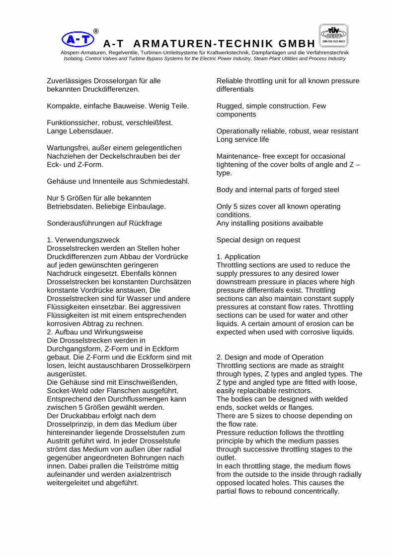
A-T ARMATUREN-TECHNIK GMBH Absperr-Armaturen, Regelventile, Turbinen-Umleitsysteme für Kraftwerkstechnik, Dampfanlagen und die Verfahrenstechnik
Isolating, Control Valves and Turbine Bypass Systems for the Electric Power Industry, Steam Plant Utilities and Process Industry
®
Zuverlässiges Drosselorgan für alle bekannten Druckdifferenzen. Kompakte, einfache Bauweise. Wenig Teile. Funktionssicher, robust, verschleißfest. Lange Lebensdauer. Wartungsfrei, außer einem gelegentlichen Nachziehen der Deckelschrauben bei der Eck- und Z-Form. Gehäuse und Innenteile aus Schmiedestahl. Nur 5 Größen für alle bekannten Betriebsdaten. Beliebige Einbaulage. Sonderausführungen auf Rückfrage 1. Verwendungszweck Drosselstrecken werden an Stellen hoher Druckdifferenzen zum Abbau der Vordrücke auf jeden gewünschten geringeren Nachdruck eingesetzt. Ebenfalls können Drosselstrecken bei konstanten Durchsätzen konstante Vordrücke anstauen, Die Drosselstrecken sind für Wasser und andere Flüssigkeiten einsetzbar. Bei aggressiven Flüssigkeiten ist mit einem entsprechenden korrosiven Abtrag zu rechnen. 2. Aufbau und Wirkungsweise Die Drosselstrecken werden in Durchgangsform, Z-Form und in Eckform gebaut. Die Z-Form und die Eckform sind mit losen, leicht austauschbaren Drosselkörpern ausgerüstet. Die Gehäuse sind mit Einschweißenden, Socket-Weld oder Flanschen ausgeführt. Entsprechend den Durchflussmengen kann zwischen 5 Größen gewählt werden. Der Druckabbau erfolgt nach dem Drosselprinzip, in dem das Medium über hintereinander liegende Drosselstufen zum Austritt geführt wird. In jeder Drosselstufe strömt das Medium von außen über radial gegenüber angeordneten Bohrungen nach innen. Dabei prallen die Teilströme mittig aufeinander und werden axialzentrisch weitergeleitet und abgeführt.
Reliable throttling unit for all known pressure differentials Rugged, simple construction. Few components Operationally reliable, robust, wear resistant Long service life Maintenance- free except for occasional tightening of the cover bolts of angle and Z –type. Body and internal parts of forged steel Only 5 sizes cover all known operating conditions. Any installing positions avaibable Special design on request 1. Application Throttling sections are used to reduce the supply pressures to any desired Iower downstream pressure in places where high pressure differentials exist. Throttling sections can also maintain constant supply pressures at constant flow rates. Throttling sections can be used for water and other liquids. A certain amount of erosion can be expected when used with corrosive liquids. 2. Design and mode of Operation Throttling sections are made as straight through types, Z types and angled types. The Z type and angled type are fitted with loose, easily replacibable restrictors. The bodies can be designed with welded ends, socket welds or flanges. There are 5 sizes to choose depending on the flow rate. Pressure reduction follows the throttling principle by which the medium passes through successive throttling stages to the outlet. In each throttling stage, the medium flows from the outside to the inside through radially opposed located holes. This causes the partial flows to rebound concentrically.

A-T ARMATUREN-TECHNIK GMBH Absperr-Armaturen, Regelventile, Turbinen-Umleitsysteme für Kraftwerkstechnik, Dampfanlagen und die Verfahrenstechnik
Isolating, Control Valves and Turbine Bypass Systems for the Electric Power Industry, Steam Plant Utilities and Process Industry
®
Verschlüssen vor jeder Inbetriebnahme überprüft und falls erforderlich nachgezogen werden. Dieses ist während des Betriebes in gewissen Zeitabständen zu wiederholen. Bei der Montage der Drosselstrecken ist darauf zu achten, dass Durchfluss und Pfeilrichtung übereinstimmen. Bei dem Einschweißen sind die entsprechenden Wärmebehandlungs- und Schweißvorschriften zu beachten. Bei der Demontage der drucklosen Drosselstrecken (nur bei der Eck- und Z-Form möglich) sind die einzelnen Teile des Verschlusses abzunehmen. Danach wird ein von uns mitgelieferter Demontagedorn in den Verschlusspilz eingeschraubt, ein Rohr als Widerlager darüber gestülpt und mittels einer am oberen Ende des Montagedorns zu schraubenden Mutter der Verschlusspilz gezogen. Das gleiche ist für den Drosselkörper zu wiederholen. Die Montage hat in der umgekehrten Reihenfolge zu erfolgen. Hierbei wird der Demontagedorn nicht benötigt. Besondere Sorgfalt ist bei dem Einlegen der Innenteile wie Packungsbuchsen und Drosseleinsätzen anzuwenden.
Before every start-up the nuts of the sealing devices of the angled and Z types must be checked and tightened if necessary. This operation must be repeated at specific intervals during operation. When assembling throttling sections, care must be taken to ensure that flow takes place in the direction of the arrow. The correct heat treatment and welding regulations must be observed when welding. When dismantling unpressurised throttling section (only possible in the case of the angled and Z types), the individual parts of the sealing device must be removed. A dismantling plug supplied by us is then screwed into the sealing obturator, a supporting tube is slipped over it and the sealing obturator withdrawn by means of a nut screwed into the upper end of the assembly plug. This operation is repeated for the flow restrictors. Assembling is carried out in the reverse order. The dismantling plug is not necessary for this. Special care must be taken when fitting the internal parts such as stuffing boxes and restrictor units.
- Drosselstrecke mit Schweisslippendichtung - Throttling section with weld sealing

A-T ARMATUREN-TECHNIK GMBH Absperr-Armaturen, Regelventile, Turbinen-Umleitsysteme für Kraftwerkstechnik, Dampfanlagen und die Verfahrenstechnik
Isolating, Control Valves and Turbine Bypass Systems for the Electric Power Industry, Steam Plant Utilities and Process Industry
®
Wasserregelventil RVW Control Valve Water RVW
A-T Armaturen-Technik GmbH Babcock T-Bldg Tel.: +49 208 833 1700 E-Mail: [email protected] Duisburger Straße 375 46049 Oberhausen / Germany Fax: +49 208 833 1755 Web: www.at-armaturen.com
®

A-T ARMATUREN-TECHNIK GMBH Absperr-Armaturen, Regelventile, Turbinen-Umleitsysteme für Kraftwerkstechnik, Dampfanlagen und die Verfahrenstechnik
Isolating, Control Valves and Turbine Bypass Systems for the Electric Power Industry, Steam Plant Utilities and Process Industry
®
Baureihe RVW in Schmiedestahlausführung für höchste Drücke und Durchsatzmengen 1. Verwendungszweck Die hier vorgestellte Baureihe RVW ist für höchste Drücke, höchste Temperaturen und Leistungen einsetzbar. Wasserregelventile RVW werden in allen Industriezweigen verwendet, bei denen Wasser auf einen niederen Druck entspannt werden soll. Die Armatur ist ein Druckreduzierventil. 2. Aufbau und Wirkungsweise Das Ventilgehäuse mit seinem seitlichen Eintrittsstutzen nimmt den fest eingeschweißten, jedoch austauschbaren, Sitz und den anschließenden Erweiterungskonus auf. Die Ventilspindel ist mit dem Kegel aus einem Stück gefertigt. Geführt über ein Lager im Ventildeckel und einem zweiten Lager im Ventileinsatz ist die Spindel schwingungsfrei gelagert. Aufsatz und Ventil sind miteinander durch eine montagefreundliche Klemmverbindung befestigt. Durch bestimmte innere Formgebung lässt sich der Geräuschpegel niedrig halten. Der von der Regeleinrichtung gegebene Impuls bewirkt über den Ventilantrieb eine Stellungsänderung des Ventilkegels. Der freigegebene Spalt zwischen Sitz und Kegel lässt das Medium hindurchfließen. Das Ventil öffnet das Medium, dichtet daher in geschlossenem Zustand vollkommen ab. Vorzüge: Unkompliziert stabiler Aufbau bei erstklassiger Bearbeitung gewährleisten einen einwandfreien Betrieb. Durch Baukastensystem ergibt sich ein günstiger Preis und kurze Lieferzeit. Betätigungsmöglichkeiten durch viele Antriebsarten.
RVW series in forged steel for highest pressure values and mass-flow through 1. Application The RVW series presented here is suitable for use under conditions of highest pressures, temperatures and outputs. RVW water regulating valves are used in all branches of industry where water pressures have to be reduced. The device is effectively a pressure reducing valve. 2. Design and mode of Operation The valve body has a lateral inlet connection and is fitted with a seat welded in place but which can be exchanged, and a dose fitting expansion cone. The valve spindle and the cone are made in one piece. The spindle is mounted so as to be free from vibration and is guided in a bush in the valve cover and a second bush in the valve core. The cover and the valve are fastened together by a clamping device which facilitates assembly. The noise level is kept low because of a special design of internal passages. The pulse from the control unit causes the valve drive to change position of valve cone. The gap between the seat and the cone allows the medium to flow. The valve can be opened against the pressure of the medium. A complete seal in the closed position is secured. Advantages: Simple, rugged construction and first quality manufacture ensure trouble-free operation. Reasonable price and short delivery times are achieved by modular construction. Many types of actuators can be adopted for operating the valves.

A-T ARMATUREN-TECHNIK GMBH Absperr-Armaturen, Regelventile, Turbinen-Umleitsysteme für Kraftwerkstechnik, Dampfanlagen und die Verfahrenstechnik
Isolating, Control Valves and Turbine Bypass Systems for the Electric Power Industry, Steam Plant Utilities and Process Industry
®
- Regelventil mit E-Antrieb - Control valve with electric actuator

A-T ARMATUREN-TECHNIK GMBH Absperr-Armaturen, Regelventile, Turbinen-Umleitsysteme für Kraftwerkstechnik, Dampfanlagen und die Verfahrenstechnik
Isolating, Control Valves and Turbine Bypass Systems for the Electric Power Industry, Steam Plant Utilities and Process Industry
®
Dampfregelventil RVD Control Valve Steam RVD
A-T Armaturen-Technik GmbH Babcock T-Bldg Tel.: +49 208 833 1700 E-Mail: [email protected] Duisburger Straße 375 46049 Oberhausen / Germany Fax: +49 208 833 1755 Web: www.at-armaturen.com
®

A-T ARMATUREN-TECHNIK GMBH Absperr-Armaturen, Regelventile, Turbinen-Umleitsysteme für Kraftwerkstechnik, Dampfanlagen und die Verfahrenstechnik
Isolating, Control Valves and Turbine Bypass Systems for the Electric Power Industry, Steam Plant Utilities and Process Industry
®
Baureihe RVD in Schmiedestahlausführung für höchste Drücke und Temperaturen 1. Verwendungszweck Die hier vorgestellte Baureihe RVD ist für höchste Drücke, höchste Temperaturen und Leistungen einsetzbar. Dampfregelventile RVD's werden in allen Industriezweigen verwendet, bei denen Dampf auf einen niederen Druck entspannt werden soll. Die Armatur ist ein Druckreduzierventil. 2. Aufbau und Wirkungsweise Das Ventilgehäuse mit seinem seitlichen Eintrittsstutzen nimmt den fest eingeschweißten, jedoch austauschbaren, Sitz und den anschließenden Erweiterungskonus auf. Die Ventilspindel ist mit dem Kegel aus einem Stück gefertigt. Geführt über ein Lager im Ventildeckel und einem zweiten Lager im Ventileinsatz ist die Spindel schwingungsfrei gelagert. Aufsatz und Ventil sind miteinander durch eine montagefreundliche Klemmverbindung befestigt. Durch bestimmte innere Formgebung und durch eventuellen Einbau einer oder mehrerer Lochscheiben lässt sich der Geräuschpegel niedrig halten. Der von der Regeleinrichtung gegebene Impuls bewirkt über den Ventilantrieb eine Stellungsänderung des Ventilkegels. Der freigegebene Spalt zwischen Sitz und Kegel lässt das Medium hindurchfließen. Das Ventil öffnet gegen das Medium, dichtet daher in geschlossenem Zustand vollkommen ab. Vorzüge: Unkomplizierter Aufbau bei erstklassiger Bearbeitung gewährleisten einen einwandfreien Betrieb. Durch Baukastensystem ergibt sich ein günstiger Preis und kurze Lieferzeit. Betätigungsmöglichkeiten durch viele Antriebsarten.
Fabrication program RVD in forged Steel for highest pressures and temperatures. 1. Application The program RVD introduced here can be applied for highest values of pressure, temperature and mass-flow-capacities. Steam control valves are used as pressure reducing valves in all types of the industry where steam required to be flashed at Iower pressures. 2. Design and mode of operation The valve body has horizontal inlet connections firmly welded, whereas the seat and the joined conical widening are removable. The valve spindle and the cone are made in one piece. Also the valve spindle with its plug is fabricated in one piece. The spindle is pivoted Vibration- free between a bush in the valve cover and a second bush in the valve seat. The cover and the valve are fastened together by a clamping device which facilitates assembly. The noise level is kept low by the special design of the internal passages. The pulse from the control unit causes the valve drive to change position of valve cone. The gap between the seat and the cone allows the medium to flow. The valve opens against the pressure of the medium. A complete seal in the closed position is secured. Advantages: Simple, rugged construction and first dass manufacture ensure trouble-free operation. Reasonable price and short delivery times are achieved by modular construction. Many types of actuators can be adopted for operation.

A-T ARMATUREN-TECHNIK GMBH Absperr-Armaturen, Regelventile, Turbinen-Umleitsysteme für Kraftwerkstechnik, Dampfanlagen und die Verfahrenstechnik
Isolating, Control Valves and Turbine Bypass Systems for the Electric Power Industry, Steam Plant Utilities and Process Industry
®
- Dampfregelventil - Steam pressure control valve

A-T ARMATUREN-TECHNIK GMBH Absperr-Armaturen, Regelventile, Turbinen-Umleitsysteme für Kraftwerkstechnik, Dampfanlagen und die Verfahrenstechnik
Isolating, Control Valves and Turbine Bypass Systems for the Electric Power Industry, Steam Plant Utilities and Process Industry
®
Dampfzustandsregelventil DZE Steam conditioning valve DZE
A-T Armaturen-Technik GmbH Babcock T-Bldg Tel.: +49 208 833 1700 E-Mail: [email protected] Duisburger Straße 375 46049 Oberhausen / Germany Fax: +49 208 833 1755 Web: www.at-armaturen.com
®

A-T ARMATUREN-TECHNIK GMBH Absperr-Armaturen, Regelventile, Turbinen-Umleitsysteme für Kraftwerkstechnik, Dampfanlagen und die Verfahrenstechnik
Isolating, Control Valves and Turbine Bypass Systems for the Electric Power Industry, Steam Plant Utilities and Process Industry
®
1 .Verwendungszweck Die hier vorgestellte Baureihe DZE ist für höchste Drücke und Temperaturen einsetzbar. Dampfzustands-Regelventile DZE werden in allen Industriezweigen verwendet, bei denen Dampf auf einen niedrigeren Druck entspannt und gleichzeitig gekühlt werden muss. Beide Aufgaben werden ohne Nachschalten eines Kühlers vom DZE übernommen. Sein Einsatz ist deshalb besonders interessant in Kraftwerken, Dampfverteilungsnetzen der chemischen Industrie sowie in Papier- und Zuckerfabriken u. a. 2. Aufbau und Wirkungsweise Das Dampfzustands - Regelventil DZE drosselt und kühlt Heißdampf in einem Ventilgehäuse. Der Betrieb dieses Ventiles ist unkompliziert, der Raumbedarf ist sehr gering, die Wirtschaftlichkeit dieses Umformventirs ist infolge seines geringen Platzbedarfs gut. Das Dampfzustands-Regelventil findet Verwendung für jeden praktisch verfügbaren Dampfzustand höchster Drücke und höchster Temperaturen bis herunter zu den niedrigsten Anfangswerten. Durchsatzmengen für dasVentil sind unbeschränkt. Sorgfältige Beobachtungen im Betrieb haben es uns ermöglicht, durch innere Formgebung, durch kompakte Bauform und durch den Einbau eines oder mehrerer Lochkegel den Geräuschpegel gering zu halten
1. Application The DZE series presented here is suitable for conditions of highest pressures and temperatures. Steam condition regulating valves of type DZE are used in all branches of industry where steam has to be simultaneously expanded to a Iower pressure and has to be cooled. The DZE carried out both duties without the need to install a cooler. For this reason its use is particularly attractive in power stations, steam distribution mains in the chemical industry and in paper mills and sugar factories etc. 2. Design and mode of Operation The steam condition regulating valve throttles and cools superheated steam in a single valve body. The operation of this valve is straightforward. It occupies very little space and is extremely economical due to its compactness and relatively Iow initial cost. The steam condition regulating valve can be applied to practically any available steam condition from the highest pressures and temperatures right down to the Iowest initial values. Through-put rates for the valves are unlimited. The coolant is not supplied directly into the steam flow, but is injected through a central hole in the valve spindle. When the valve is opened, a relatively smaller flow from the main steam supply automatically enters an annular chamber in the regulating cone and starts to vapourize the centrally supplied coolant immediately it leaves the regulating cone. The auxiliary steam flow immediately heats the coolant approximately to evaporation temperature. Even under conditions of partial through-flow this ensures thorough mixing.

A-T ARMATUREN-TECHNIK GMBH Absperr-Armaturen, Regelventile, Turbinen-Umleitsysteme für Kraftwerkstechnik, Dampfanlagen und die Verfahrenstechnik
Isolating, Control Valves and Turbine Bypass Systems for the Electric Power Industry, Steam Plant Utilities and Process Industry
®
- Dampfregelventil - Steam pressure control valve

A-T ARMATUREN-TECHNIK GMBH Absperr-Armaturen, Regelventile, Turbinen-Umleitsysteme für Kraftwerkstechnik, Dampfanlagen und die Verfahrenstechnik
Isolating, Control Valves and Turbine Bypass Systems for the Electric Power Industry, Steam Plant Utilities and Process Industry
®
HD-Bypass Station DN 150/600 Type DZEK-RD-LK5 HP-turbine bypass DN 150/600 Type DZEK-RD-LK5
Gehäuse Eckform geschmiedet forged angular body
Hydraulikzylinder doppeltwirkend double acting hydraulic piston

A-T ARMATUREN-TECHNIK GMBH Absperr-Armaturen, Regelventile, Turbinen-Umleitsysteme für Kraftwerkstechnik, Dampfanlagen und die Verfahrenstechnik
Isolating, Control Valves and Turbine Bypass Systems for the Electric Power Industry, Steam Plant Utilities and Process Industry
®
HD-Bypass Station DN 300/800 Type DZEK-RD-LK3 HP-turbine bypass DN 300/800 Type DZEK-RD-LK3
Pneumatikzylinder doppeltwirkend double acting pneumatic cylinder
Gehäuse Z-Form geschmiedet forged Z-type body

A-T ARMATUREN-TECHNIK GMBH Absperr-Armaturen, Regelventile, Turbinen-Umleitsysteme für Kraftwerkstechnik, Dampfanlagen und die Verfahrenstechnik
Isolating, Control Valves and Turbine Bypass Systems for the Electric Power Industry, Steam Plant Utilities and Process Industry
®
Vorwärmerabsicherung UV/SV Preheater bypass system UV/SV
A-T Armaturen-Technik GmbH Babcock T-Bldg Tel.: +49 208 833 1700 E-Mail: [email protected] Duisburger Straße 375 46049 Oberhausen / Germany Fax: +49 208 833 1755 Web: www.at-armaturen.com
®

A-T ARMATUREN-TECHNIK GMBH Absperr-Armaturen, Regelventile, Turbinen-Umleitsysteme für Kraftwerkstechnik, Dampfanlagen und die Verfahrenstechnik
Isolating, Control Valves and Turbine Bypass Systems for the Electric Power Industry, Steam Plant Utilities and Process Industry
®
Vorwärmerabsicherungen 1.1 Verwendungszweck Um den Wirkungsgrad einer Dampfkesselanlage zu erhöhen, wird das vom Speisewasserbehälter zum Kessel strömende Speisewasser durch einen Vorwärmer beheizt. Der Vorwärmer ist ein Wärmetauscher, durch dessen Rohre das Speisewasser strömt. Von außen werden die Rohre mit Abzapfdampf von der Turbine beaufschlagt. Bei einem evtl. Leck im Rohrsystem strömt Wasser mit höherem Druck in den Dampfraum mit niederem Druck. Um jetzt Schäden zu vermeiden, und zwar durch a) Eindringen von Speisewasser in die Turbine b) Aufbau eines unzulässigen Druckes im Vorwärmermantel muss der Vorwärmer schnellstens von der Speisewasserdruckleitung getrennt werden. Dieses erfolgt durch eine Vorwärmerabsicherung, d. h. durch am Ein- und Austritt des Vorwärmers angeordnete, eigenmedium- gesteuerte Schnellschlußarmaturen. Hierbei wird normalerweise am Eintritt eine Umschaltarmatur und am Austritt eine Absperrarmatur angeordnet. 2.1 Aufbau und Wirkungsweise Die nachfolgend gezeigten Schaltschemata geben einige Anordnungen und deren Steuerorgane wieder. Die Schaltschemata zeigen die Armaturen in normaler Arbeitsstellung, bei geöffnetem Vorwärmerstrang und gesperrter Bypassleitung. Zu allen Schaltschemata gilt folgende Wirkungsweise:
Preheater bypass system 1.1 Application To improve the efficiency of a steam vessel System, feed-water, flowing from the feed-water tank to the vessel, is heated by a preheater. The preheater is a heat exchanger with tubes containing feed-water. From the outside, the tubes receive steam drawn-off from the turbine. In the case of a leakage in the tubing System, water of higher pressure rushes into the vapor room of Iower pressure. To avoid any damages by a) penetration of feed-water into the turbine b) build-up of inadmissible pressure in the preheater jacket, the preheater must be separated from the feed-water pressure tube äs soon äs possible. This will be provided by the preheater protection unit, i.e. by quick ciosing valves which are controlled by their own medium and located at the in- and outlet of the preheater. Normally a change-over valve is located at the inlet and a stop valve at the outlet. 2.1 Construction and function The following circuit diagrams show some arrangements together with their control units. The circuit diagrams show the valves in normal working position with opened preheater pipe train and locked bypass tube. All circuit diagrams have the following functions:

A-T ARMATUREN-TECHNIK GMBH Absperr-Armaturen, Regelventile, Turbinen-Umleitsysteme für Kraftwerkstechnik, Dampfanlagen und die Verfahrenstechnik
Isolating, Control Valves and Turbine Bypass Systems for the Electric Power Industry, Steam Plant Utilities and Process Industry
®
2.1.1 Funktion beim automatischen Umschalten auf Bypass Der Niveauwächter gibt einen elektrischen Impuls auf das Steuerventil, welches die Entlastungsleitung frei gibt. Der Druck unter dem Steuerkolben der Hauptventile wird abgebaut. Das Umschaltventil und das Schnellschlußventil schalten durch die Differenzdruckkraft am Kolben um. Die Verbindungsbohrung im Verschlußpilz bewirkt den Druckausgleich zwischen dem Raum über dem Steuerkolben und der Speisewasserleitung. Durch die Drosselventile kann die Umschaltgeschwindigkeiteingestelltwerden. Danach Blockierung der beiden Hauptventile durch Niederschrauben der Gewindespindel. Die Blockierspin- dein bewirken durch ihr Niederschrauben eine Erhöhung der Dichtkraft an den Absperrsitzen. 2.1.2 Rückstellen der beiden Haupt-Ventile auf Normalbetrieb Die Blockierspindeln beider Haupt-Ventile bis in Stellung „Vorwärmerstrang auf drehen. Der Vorwärmer ist über Absperrventile zu füllen und auf Betriebsdruck zu bringen. Bei einem Innendruck von mind. 50 bar Druckausgleich an allen Stellen, schalten die Ventile um. Bei kleineren gewünschten Umschaltdrücken ist der Umschalt druck anzugeben. Bei sehr kleinen Umschaltdrücken ist zusätzlich der obere Steuerkolbenraum durch Öffnen eines weiteren Ventils zu entlasten. Infolge des wirksamen Spindelauftriebes in der Stellung „Vorwärmer auf, und ggf. durch Entlastung des oberen Kolbenraumes, schalten die Vorwärmerabsicherungsventile um. Zur Herstellung der Betriebsbereitschaft sind dann noch die Absperrventile zu schließen. Die Steckkupplung dient lediglich zur Verstellung der Ventile in drucklosem Zustand durch das Handrad. Hierbei muss das Absperrventil in jedem Falle geöffnet sein. Die Steckkupplung ist nach Betätigung sofort abzuziehen. Die Absperrfüllventile dienen nur zum Auffüllen des Vorwärmers und sind danach immerzu schließen.
2.1.1 Function with automatic switch-over to bypass The level sensor feeds an electrical pulse to the control valve which opens the relief tube. Pressure under the control piston of the main valves is reduced. Because of the pressure difference, the change-over and the quick stop valves shift at the piston. The interconnecting bore in the sealing plug provides for the pressure compensation between the space above the control piston and the feed-water tube. The switching speed can be adjusted by the Flow control valves. Subsequently both valves are blocked through the screwed down threaded spindle. An increase of the tightening force on the blocking spindles improves the sealing at the valve seats. 2.1.2 Resetting the two main valves to Standard position Rotate the locking spindles of the two main valves up to position 'Preheater pipe train open'. Fill the preheater through the stop valves up to working pressure. At an internal pressure of min. 50 bars pressure compensation at any position, the valves will shift over. If you want the valves to shift at Iower pressure, you must position the pressure. With very Iow shifting pressures the upper control piston space must be relieved by opening another valve. Due to the current spindle lifting force in position 'preheater open' it ought to be necessary to relief the upper piston space, the preheater protection valves shift. To revert to normal Operation, you must shut the stop valves. The plug coupling is only used for adjusting the valves with the hand wheel in unpressurerized condition. In this case, the stop valve must always be closed. Pull-off the plug coupling immediately after use. The stop valves are used for filling the preheater - always close them after filling the preheater.

A-T ARMATUREN-TECHNIK GMBH Absperr-Armaturen, Regelventile, Turbinen-Umleitsysteme für Kraftwerkstechnik, Dampfanlagen und die Verfahrenstechnik
Isolating, Control Valves and Turbine Bypass Systems for the Electric Power Industry, Steam Plant Utilities and Process Industry
®
3.1 Aufbau und Wirkungsweise Die nachfolgend gezeigten Schaltschemata geben einige Anordnungen und deren Steuerorgane wieder. Die Schaltschemata zeigen die Armaturen in normaler Arbeitsstellung, bei geöffnetem Vorwärmerstrang und gesperrter Bypass-Leitung. Vorwärmerabsicherungen: Schaltschema 1 Funktion beim automatischen Umschalten auf Bypass. Das Magnetsteuerventil erhält vom Niveauwächter einen elektrischen Impuls und gibt die Impulsleitung frei. Der Druck unter dem Steuerkolben der Hauptventile baut ab und Umschaltventil und Schnellschlußventil schalten um. Die Entlastungsbohrung im Gehäuseverschluß bewirkt den Druckausgleich zwischen dem Raum über dem Steuerkolben und der Speisewasserleitung. Durch die Drosselventile werden die Umschaltgeschwindigkeiten eingestellt. Die Blockierung der beiden Ventile geschieht durch das Niederschrauben der Gewindespindel.
3.1 Construction and function The following diagrams show some arrangements with their control units. The circuit diagrams show the valves in Standard working position with opened preheater pipe train and locked bypass tube. Preheater protection units, circuit diagram 1 Function during automatic shifting to bypass. The solenoid control valve receives an electrical pulse from the level sensor and releases the pulse tube. The pressure below the control piston of the main valves decreases, and both, the change-over valve and the quick stop valve shift. The compensation bore in the casing closure serves to compensate the pressure between the space above the control piston and the feed-water tube. The shifting speeds are set by the flow control valves. Blocking the two valves is carried out by screwing-down the threaded spindles.
Schema 1 - Eigenmedium Steuerung - Feedwater operated

A-T ARMATUREN-TECHNIK GMBH Absperr-Armaturen, Regelventile, Turbinen-Umleitsysteme für Kraftwerkstechnik, Dampfanlagen und die Verfahrenstechnik
Isolating, Control Valves and Turbine Bypass Systems for the Electric Power Industry, Steam Plant Utilities and Process Industry
®
Vorwärmerabsicherungen: Schaltschema 2 Vorwärmer einsträngig, Steuerung durch Steuerventil mit Elektroantrieb Das Steuerventil mit elektromotorischem Antrieb erhält vom Niveauwächter einen elektrischen Impuls und gibt die Impulsleitung frei. Der Druck unter dem Steuerkolben der beiden Hauptventile baut sich ab und Umschaltventil und Schnellschlussventil schalten um. Durch die Drosselventile kann die Umschaltgeschwindigkeit beider Hauptarmaturen einzeln eingestellt werden. Die Blockierung der beiden Ventile in Bypass-Stellung geschieht durch Niederschrauben der Gewindespindel.
Preheater protection units, circuit diagram 2 Single-stranded preheater Control by control valve with electric drive The control valve with electric drive receives an electrical pulse from the level sensor and opens the pulse tube. The pressure below the control piston of the two main valves decreases, and both, the change over valve and the quick stop valve shift. The shifting speed of the two main valves can be set individually by the flow control valves. Blocking the two valves in bypass-position is carried out by screwing down the threaded spindle.
Schema 2 - Elektrische Steuerung - electric operated

A-T ARMATUREN-TECHNIK GMBH Absperr-Armaturen, Regelventile, Turbinen-Umleitsysteme für Kraftwerkstechnik, Dampfanlagen und die Verfahrenstechnik
Isolating, Control Valves and Turbine Bypass Systems for the Electric Power Industry, Steam Plant Utilities and Process Industry
®
Umschaltventil UV Die Hauptarmaturen innerhalb der Absicherung sind die Umschaltventile UV. Die Abbildung zeigt das Umschaltventil in Arbeitsstellung. Der Weg von der Pumpe zum Vorwärmer ist freigegeben, die Bypassleitung dagegen abgesperrt. Die Steckkupplung ist entfernt und das Steuerventil geschlossen. Über und unter dem Kolben herrscht bei dieser Stellung gleicher Druck. Wartungsarbeiten: Bei Inbetriebnahme sind die Druckschrauben und gegebenenfalls auch die Stopfbuchsmuttern nachzuziehen. Die Blockierspindel mit Gewindebüchse und die Kugellager werden für den Revisionszeitraum mit Molykote HSC (—30° + 1100° C) eingesetzt.
Change-over valve The main valves of the protection system are the change-over valves UV. The figure shows the change-over valve in working position. The passage from the pump to the preheater is unlocked, the bypass is blocked. The plug coupling is removed and the control valve closed. There is equal pressure above and below the piston in this position. Maintenance: During commissioning, the pressure screws and - if necessary - the gland nuts must be retightened. The blocking spindle with threaded sleeve and the ball bearings are lubricated with Molycote HSC (-30° +1100°C) for the commissioning period.
- Umschaltventil - 3 way inlet valve

A-T ARMATUREN-TECHNIK GMBH Absperr-Armaturen, Regelventile, Turbinen-Umleitsysteme für Kraftwerkstechnik, Dampfanlagen und die Verfahrenstechnik
Isolating, Control Valves and Turbine Bypass Systems for the Electric Power Industry, Steam Plant Utilities and Process Industry
®
Schnellschlussventil SV Neben den Umschaltventilen zählen die Schnellschlußventile zu den Hauptarmaturen. Die Abbildung zeigt das Schnellschlußventil in Arbeitsstellung. Der Weg vom Vorwärmer zum Kessel ist freigegeben. Die Steckkupplung ist entfernt und das Steuerventil geschlossen. Über und unter dem Kolben herrscht bei dieser Stellung gleicher Druck. Wartungsarbeiten: Bei Inbetriebnahme sind die Druckschrauben und gegebenenfalls auch die Stopfbuchsmuttern nachzuziehen. Die Blockierspindel mit Gewindebüchse und die Kugellager werden für den Revisionszeitraum mit Molykote HSC (—30° +1100° C) eingesetzt.
Quick - Stop valve SV In addition to the change-over valves, the quick stop valves also belong to the main valves. The passage from the preheater to the vessel is unlocked. The plug coupling is removed and the control valve closed. There is equal pressure above and below the piston in this position. Maintenance: During commissioning, the pressure screws and -if necessary- the gland nuts must be retightened. The blocking spindle with threaded sleeve and the ball bearings are lubricated with Molycote HSC (-30° +1100°C) for the commissioning period.
- Schnellschlussventil - 3 way outlet valve

A-T ARMATUREN-TECHNIK GMBH Absperr-Armaturen, Regelventile, Turbinen-Umleitsysteme für Kraftwerkstechnik, Dampfanlagen und die Verfahrenstechnik Isolating, Control Valves and Turbine Bypass Systems for the Electric Power Industry, Steam Plant Utilities and Process Industry
84
®
List of References ( Extract only )

A-T ARMATUREN-TECHNIK GMBH Absperr-Armaturen, Regelventile, Turbinen-Umleitsysteme für Kraftwerkstechnik, Dampfanlagen und die Verfahrenstechnik Isolating, Control Valves and Turbine Bypass Systems for the Electric Power Industry, Steam Plant Utilities and Process Industry
®
REFERENZLISTE - HD-Spezial Armaturen REFERENCE LIST HP-
special valves Customer Product Material/Size design data Plant Kunde Produkt Werkstoff/DN Berechnungsdaten
Anlage KWU check valve 13 CrMo 44 42,5 bar KW-
Rückschlagklappe DN 800 311 °C Ibbenbüren VKR preheater-bypass 15 NiCuMoNb 5 370 bar FWK Buer Vorw.-Absicherung DN 200 300 °C KW-
Scholven VKR gate valve X 20 CrMo V 121 281 bar FWK Buer Schieber DN 200 540 °C KW-
Scholven VKR control valve 10 CrMo 910 281 bar FWK Buer Ventil DN 80 540 °C KW-
Scholven VKR gate valve 10 CrMo 910 281 bar FWK Buer Schieber DN 80 540 °C KW-
Scholven VKR gate valve 10 CrMo 910 281 bar FWK Buer Schieber DN 50 540 °C KW-
Scholven VKR gate valve 10 CrMo 910 61 bar
FWK Buer Schieber DN 80 540 °C KW-
Scholven VKR gate valve 15 Mo 3 61 bar
FWK Buer Schieber DN 80 400 °C KW-
Scholven VKR check valve 15 NiCuMoNb 5 370 bar
FWK Buer Rückschlagklappe DN 200 290 °C KW-
Scholven VKR gate valve 15 NiCuMoNb 5 370 bar
FWK Buer Schieber DN 200 290 °C KW-
Scholven
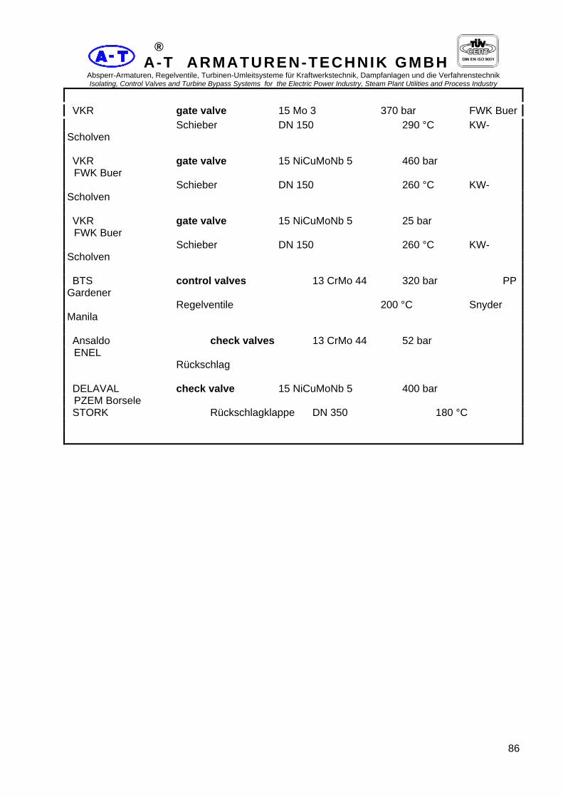
A-T ARMATUREN-TECHNIK GMBH Absperr-Armaturen, Regelventile, Turbinen-Umleitsysteme für Kraftwerkstechnik, Dampfanlagen und die Verfahrenstechnik Isolating, Control Valves and Turbine Bypass Systems for the Electric Power Industry, Steam Plant Utilities and Process Industry
86
®
VKR gate valve 15 Mo 3 370 bar FWK Buer Schieber DN 150 290 °C KW-
Scholven VKR gate valve 15 NiCuMoNb 5 460 bar
FWK Buer Schieber DN 150 260 °C KW-
Scholven VKR gate valve 15 NiCuMoNb 5 25 bar
FWK Buer Schieber DN 150 260 °C KW-
Scholven BTS control valves 13 CrMo 44 320 bar PP
Gardener Regelventile 200 °C Snyder
Manila Ansaldo check valves 13 CrMo 44 52 bar
ENEL Rückschlag DELAVAL check valve 15 NiCuMoNb 5 400 bar
PZEM Borsele STORK Rückschlagklappe DN 350 180 °C

A-T ARMATUREN-TECHNIK GMBH Absperr-Armaturen, Regelventile, Turbinen-Umleitsysteme für Kraftwerkstechnik, Dampfanlagen und die Verfahrenstechnik Isolating, Control Valves and Turbine Bypass Systems for the Electric Power Industry, Steam Plant Utilities and Process Industry
87
®
REFERENZLISTE - HD-Spezial-Armaturen REFERENCE LIST HP-
special valves Customer Product Material/Size design data Plant Kunde Produkt Werkstoff/DN Berechnungsdaten
Anlage DELAVAL check valve 15 Mo 3 34 bar STORK Rückschlagklappe DN 300 400 °C VKR 3-way mixing valve H II 10 bar
FWK Buer Dreiwegemischschieber DN 300/300/250 50 °C
KW-Scholven VKR 3-way mixing valve H II 25 bar
FWK Buer Dreiwegemischschieber DN 500/500/500 150 °C KW-
Scholven DELAVAL check valve 15 NiCuMoNb 5 250 bar
PZEM Borsele STORK Rückschlagklappe DN 250 180 °C ELSONT check valve 13 CrMo 44 358 bar KW-
Brasilien Rückschlagklappe DN 400 180 °C IPP-Oslo control valves C 22.8 100 bar Regelventile DN 100 20 °C GKW gate valve 15 Mo 3 240 bar KW-
Franken II Franken Schieber DN 65 200 °C GKW gate valve 14 Mo V 63 35 bar
KW-Franken II Franken Schieber DN 350/300 545 °C GKW gate valve 14 Mo V 63 35 bar
KW-Franken II Franken Schieber DN 450 545 °C AEG Kanis check valve 13 CrMo 44 PN 160 Rückschlagklappe DN 200 STEAG gate valve C 22.8 PN 160 KW-Herne Schieber DN 100 Stadtwerke gate valve 15 Mo 3 PN 160 Duisburg Schieber DN 80

A-T ARMATUREN-TECHNIK GMBH Absperr-Armaturen, Regelventile, Turbinen-Umleitsysteme für Kraftwerkstechnik, Dampfanlagen und die Verfahrenstechnik Isolating, Control Valves and Turbine Bypass Systems for the Electric Power Industry, Steam Plant Utilities and Process Industry
88
®
Stadtwerke gate valve 10 CrMo 910 115 bar Neumünster Schieber DN 150 530 °C VAG gate valve C 22.8 290 bar Bayer Schieber DN 80 160 °C
Leverkusen VAG gate valve C 22.8 290 bar Bayer Schieber DN 50 160 °C
Leverkusen STEINMÜLLER check valve C 22.8 123 bar
Zuckerfabrik Rückschlagklappe DN 125 327 °C
Nordstemmen

A-T ARMATUREN-TECHNIK GMBH Absperr-Armaturen, Regelventile, Turbinen-Umleitsysteme für Kraftwerkstechnik, Dampfanlagen und die Verfahrenstechnik Isolating, Control Valves and Turbine Bypass Systems for the Electric Power Industry, Steam Plant Utilities and Process Industry
89
®
REFERENZLISTE - HD-Spezial-Armaturen REFERENCE LIST HP-
special valves Customer Product Material/Size design data Plant Kunde Produkt Werkstoff/DN Berechnungsdaten
Anlage STEINMÜLLER gate valve C 22.8 123 bar
Zuckerfabrik Schieber DN 125 327 °C
Nordstemmen STEINMÜLLER gate valve 10 CrMo 910 100 bar
Zuckerfabrik Schieber DN 200 535 °C
Nordstemmen STEINMÜLLER control valves 10 CrMo 910 100 bar
Zuckerfabrik Regelventile DN 100 535 °C
Nordstemmen STEINMÜLLER gate valve 10 CrMo 910 100 bar
Zuckerfabrik Schieber DN 100 535 °C
Nordstemmen VAG gate valve 13 CrMo 44 103 bar
Technocommerz Schieber DN 250/200 525 °C ehem. DDR VAG/ gate valve 10 CrMo 910 89 bar
Alfelder Siemens Schieber DN 175 535 °C
Papierfabrik STEINMÜLLER gate valve 15 NiCuMoNb 5 344 bar
STEAG Schieber DN 250 380 °C HKW
Herne IV STEINMÜLLER check valve 15 NiCuMoNb 5 344 bar
STEAG Rückschlagklappe DN 250 380 °C HKW
Herne IV STEINMÜLLER gate valve 15 NiCuMoNb 5 344 bar
STEAG Schieber DN 125 380 °C HKW
Herne IV

A-T ARMATUREN-TECHNIK GMBH Absperr-Armaturen, Regelventile, Turbinen-Umleitsysteme für Kraftwerkstechnik, Dampfanlagen und die Verfahrenstechnik Isolating, Control Valves and Turbine Bypass Systems for the Electric Power Industry, Steam Plant Utilities and Process Industry
90
®
STEINMÜLLER check valve 15 NiCuMoNb 5 344 bar STEAG Rückschlagklappe DN 125 380 °C HKW
Herne IV STEINMÜLLER pressure seal cover 15 NiCuMoNb 5 316 bar
STEAG selbstdichtender Deckel ∅ 340 mm 380 °C HKW
Herne IV VAG 3-way mixing valve H II 10 bar
Isar-Amper- Dreiwegemischschieber DN 300/300/250 50 °C
Werke AG VAG gate valve 13 CrMo 44 125 bar VW
Kraftwerk Schieber DN 125 500 °C Wolfsburg VALVO gate valve 14 MoV 63 164 bar Schieber DN 200 545 °C VAG control valves C 22.8 / St 35.8 13 bar
Isar Amper- Regelventile DN 100 250 °C werke AG VAG/ 3-way mixing valve H II 26 bar
Stadtwerke Mauell Dreiwegemischschieber DN 300/300/300 150 °C Kassel

A-T ARMATUREN-TECHNIK GMBH Absperr-Armaturen, Regelventile, Turbinen-Umleitsysteme für Kraftwerkstechnik, Dampfanlagen und die Verfahrenstechnik Isolating, Control Valves and Turbine Bypass Systems for the Electric Power Industry, Steam Plant Utilities and Process Industry
91
®
REFERENZLISTE - HD-Spezial-Armaturen REFERENCE LIST HP-
special valves Customer Product Material/Size design data Plant Kunde Produkt Werkstoff/DN Berechnungsdaten
Anlage IPU steam conditioning cv 10 CrMo 910 / 140 bar
Polen Dampfumformventil DN 250/400 520 °C IPU spraywater cv 15 Mo 3 250 bar
Polen Einspritzwasser RV DN 50 250 °C ELSONT AG steam control valve 13 CoMo 44 115 bar Dampfregelventil DN 65/250 505 °C STEINMÜLLER pressure seal cover 15 NiCuMoNb 5 245 bar
KW Weiher III selbstdichtender Deckel ∅ 180 mm 410 °C Berliner Wasser- air control valves St 35.8 / H II PN 10
Klärwerk Betriebe Luftregelventil DN 600/700
Ruhleben IMPEXMETAL gate valve 13 CrMo 44 124 bar Polen Schieber DN 100 520 °C IMPEXMETAL gate valve 13 CrMo 44 124 bar Polen Schieber DN 200 520 °C BABCOCK 3-way mixing valve H II 22 bar
Preussen Oberhausen Dreiwegemischschieber 210 °C Elektra DN 250/150/250 KW-
Staudinger BABCOCK 3-way mixing valve H II PN 25
Preussen El. Oberhausen Dreiwegemischschieber DN 300/300/300 KW-
Staudinger UHDE gate valve X 20 CrMo V 121 170 bar BASF Dortmund Schieber DN 4" 545 °C Antwerpen UHDE gate valve X 20 CrMo V 121 170 bar BASF Dortmund Schieber DN 10" 545 °C Antwerpen

A-T ARMATUREN-TECHNIK GMBH Absperr-Armaturen, Regelventile, Turbinen-Umleitsysteme für Kraftwerkstechnik, Dampfanlagen und die Verfahrenstechnik Isolating, Control Valves and Turbine Bypass Systems for the Electric Power Industry, Steam Plant Utilities and Process Industry
92
®
BABCOCK feedwatercontol valve GS-17CrMo55/15 Mo 3 150 bar PAKA / PASIR Oberhausen Speisewasserregelventil DN 200 343 °C Malaysia BABCOCK feedwatercontol valve GS-17CrMo55/15 Mo 3 150 bar
PAKA / PASIR Oberhausen Speisewasserregelventil DN 100 343 °C Malaysia BABCOCK start up contol valve 15Mo3 87 bar
PAKA / PASIR Oberhausen Anfahrregelventil DN 150/250 301 °C Malaysia STANDARDKESSEL start up contol valve 13 CrMo 44 69 bar
Kali + Salz AG Anfahrregelventil 505 °C Werk
Hattorf

A-T ARMATUREN-TECHNIK GMBH Absperr-Armaturen, Regelventile, Turbinen-Umleitsysteme für Kraftwerkstechnik, Dampfanlagen und die Verfahrenstechnik Isolating, Control Valves and Turbine Bypass Systems for the Electric Power Industry, Steam Plant Utilities and Process Industry
93
®
REFERENZLISTE - HD-Spezial-Armaturen REFERENCE LIST HP-
special valves Customer Product Material/Size design data Plant Kunde Produkt Werkstoff/DN Berechnungsdaten
Anlage STANDARDKESSEL start up contol valve 13 CrMo 44 69 bar
Kali + Salz AG Anfahrregelventil 505 °C Werk
Hattorf ELSONT AG pressure red. element C 22.8 138 bar
Tschechien Drosselstrecke DN 40 105 °C Thyssen Berlin steam control valve 10 CrMo 910 52 bar
STIGNÆSVÆRKET Dampfregelventile DN 80 555 °C Dänemark Thyssen Berlin steam control valve 15 Mo 3 52 bar
STIGNÆSVÆRKET Dampfregelventile DN 80 365 °C Dänemark KEPCO parallel-slide-valve 15 Mo 3 PN 400
ULSAN Parallel Schieber DN 100/80 Korea KEPCO check valve 15 Mo 3 PN 400
ULSAN Rückschlagkappen DN 100/80 Korea TISZAI ERÖMÜ gate valve 10 CoMo 910 172 bar KW
TISZAI Schieber DN 125 550 °C Ungarn TISZAI ERÖMÜ steam control valve 10 CoMo 910 172 bar KW
TISZAI Dampfregelventil DN 125 550 °C Ungarn PROMETAL atomising steam nozzel 13 CrMo 44 KW Lillo Treibdampfdüse Belgien CEPSA gate valve C 22.8 90 bar
SANTA CRUZ Schieber DN 125/100 200 °C DE
TENERIFE KEPCO minimum flow valve 15 Mo 3 250 bar
ULSAN Mindestmengenventil DN 65/65 155 °C Korea

A-T ARMATUREN-TECHNIK GMBH Absperr-Armaturen, Regelventile, Turbinen-Umleitsysteme für Kraftwerkstechnik, Dampfanlagen und die Verfahrenstechnik Isolating, Control Valves and Turbine Bypass Systems for the Electric Power Industry, Steam Plant Utilities and Process Industry
94
®
PROMETAL pressure red. element X 10 CrNiNb 189 138 bar Elektrabel Drosselstrecke DN 50 105 °C Belgien ATS gate valve 10 CrMo 910 110 bar LAUBAG Schieber DN 100/80 535 °C VOEST - ALPINE 3-way mixing valve HII 55 bar
BAODUST Dreiwegemischschieber DN 450/450/450 258 °C China BABCOCK pressure seal cover X 20 CrMoV 121 136 bar VW Werk Osterrode selbstdichtender Deckel ∅ 275 540 °C
Wolfsburg STEINMÜLLER gate valve 10 CrMo 910 80 bar
Kali & Salz AG Schieber DN 125/100 525 °C Werk
Neuhof ENEL gate valve 10 CrMo 910 165 bar KW Porto Schieber DN 80 / 80 540 °C Corsini

A-T ARMATUREN-TECHNIK GMBH Absperr-Armaturen, Regelventile, Turbinen-Umleitsysteme für Kraftwerkstechnik, Dampfanlagen und die Verfahrenstechnik Isolating, Control Valves and Turbine Bypass Systems for the Electric Power Industry, Steam Plant Utilities and Process Industry
95
®
REFERENZLISTE - HD-Spezial-Armaturen REFERENCE LIST HP-
special valves Customer Product Material/Size design data Plant Kunde Produkt Werkstoff/DN Berechnungsdaten
Anlage PROMETAL minimum flow valve 15 Mo 3 250 bar Belgien Mindestmengenventil DN 65/65 147 °C HOLTZMANN steam conditioning cv 10 CrMo 910 93 / 3,5 bar
HOLTZMANN & CIE. AG Dampfumformventil DN 100/500 535 / 180 °C
Karlsruhe HOLTZMANN spraywater cv 15 Mo 3 130 / 60 bar
HOLTZMANN & CIE. AG Einspritzwasser RV DN 40 130 °C Karlsruhe
VW Kraftwerk gate valve 13 CrMo 44 125 bar VW
Kraftwerk GmbH Flansch-Schieber DN 125 500 °C HKW -
West CAFFARO gate valve C 22.8 250 bar IND.
HIMICHE S.P.A. Schieber DN 175 / 175 215 °C
TORVISCOSA BABCOCK pressure seal cover 10 CrMo 910 210 bar
Schwandorf Osterrode selbstdichtender Deckel ∅ 140 540 °C BABCOCK pressure seal cover 10 CrMo 910 55 bar
Schwandorf Osterrode selbstdichtender Deckel ∅ 160 540 °C MEG gate valve 15 Mo 3 250 bar Abu Dhabi Schieber DN 65 / 65 180 °C PROMETAL gate valve 10 CrMo 910 40 bar
HYDROAGRI Schieber DN 20“ / 400 500 °C PROMETAL gate valve 10 CrMo 910 40 bar
HYDROAGRI Schieber DN 14“ / 310 500 °C ZIKESCH Armaturen gate valve 15 NiCuMoNb 5 235 bar Technik Schieber DN 200 / 200 425 °C ZIKESCH Armaturen gate valve C22.8 180 bar

A-T ARMATUREN-TECHNIK GMBH Absperr-Armaturen, Regelventile, Turbinen-Umleitsysteme für Kraftwerkstechnik, Dampfanlagen und die Verfahrenstechnik Isolating, Control Valves and Turbine Bypass Systems for the Electric Power Industry, Steam Plant Utilities and Process Industry
96
®
Technik Schieber DN 175 / 150 250 °C PROMETAL gate valve 15 Mo 3 127 bar
HYDROAGRI Schieber DN 12“ / 260 450 °C PROMETAL gate valve 15 Mo 3 127 bar
HYDROAGRI Schieber DN 16“ / 325 450 °C HP-VALVES gate valve X 10 CrMoVNb 91 151 bar Schieber DN 12“ / 240 571 °C HP-VALVES globe valve (Z) X 10 CrMoVNb 91 151 bar Absperrventil in Z-Form DN 4“ / 85 571 °C PROMETAL check valves 15 Mo 3 250 bar Electrabel Rückschlagklappe DN 350 250 °C

A-T ARMATUREN-TECHNIK GMBH Absperr-Armaturen, Regelventile, Turbinen-Umleitsysteme für Kraftwerkstechnik, Dampfanlagen und die Verfahrenstechnik Isolating, Control Valves and Turbine Bypass Systems for the Electric Power Industry, Steam Plant Utilities and Process Industry
97
®
REFERENZLISTE - HD-Spezial-Armaturen REFERENCE LIST HP-
special valves Customer Product Material/Size design data Plant Kunde Produkt Werkstoff/DN Berechnungsdaten
Anlage Industrie Armaturen check valves 15 Mo 3 56 bar
BAYER Polte GmbH Rückschlagklappe DN 125 450 °C Uerdingen Industrie Armaturen check valves 15 Mo 3 56 bar
BAYER Polte GmbH Rückschlagklappe DN 200 450 °C Uerdingen Industrie Armaturen gate valve 15 Mo 3 140 bar ELENAC
Polte GmbH Schieber DN 80 / 80 350 °C Wesseling Industrie Armaturen discharge contol valve 15 Mo 3 140 bar
ELENAC Polte GmbH Ablaufregelventil DN 80 / 80 350 °C Wesseling PROMETAL steam control valve 13 CoMo 44 70 bar Dampfregelventil DN 200 / 200 480 °C BAOTEX 3-way mixing valve HII 55 bar
BAOTEX Dreiwegemischschieber DN 450/450/450 258 °C China BAOSTELL 3-way mixing valve HII 55 bar
BAOSTEEL Dreiwegemischschieber DN 450/450/450 258 °C China BABCOCK pressure seal cover X 10 CrMoVNb 91 51 bar KW
Emden Osterrode selbstdichtender Deckel ∅ 540 550 °C VKR
Thyssen, Berlin LP bypass Isolating valve10 CrMo 910 47 bar KW
Kangal Schnellschlußventil DN 350 / 350 535 °C Cepsa gate valve 15 Mo 3 75 bar
Tenerife Schieber DN 125/125 450 °C WM gate valve C 22.8 190 bar Polen Zaklad Schieber DN 65/65 300 °C

A-T ARMATUREN-TECHNIK GMBH Absperr-Armaturen, Regelventile, Turbinen-Umleitsysteme für Kraftwerkstechnik, Dampfanlagen und die Verfahrenstechnik Isolating, Control Valves and Turbine Bypass Systems for the Electric Power Industry, Steam Plant Utilities and Process Industry
98
®
Siemens gate valve 13 Cr Mo 44 60bar Enstedtvaerket KWU Drosselschieber DN 350/350 500 °C Dänemark Bariven steam control valve 13 Cr Mo 44 78 bar El
Tablazo Dampfregelventil DN 8”/10” 500 °C Venezuela Novamat spraywater cv 15 Mo 3 144 bar
Osijek Einspritzventil DN 40/40 160 °C Novamat spraywater cv 15 Mo 3 144 bar
Osijek Einspritzventil DN 50/50 160 °C Babcock pressure seal cover 10 CrMo 910 51 bar
Osterode Osterode Selbstd.DeckelverschlußDN 460 540 °C HP Valves gate valve 13 Cr Mo 94 bar
Ajalankoski Oldenzaal Schieber DN 150/150 530 °C REFERENZLISTE - HD-Spezial-Armaturen REFERENCE LIST HP-
special valves Customer Product Material/Size design data Plant Kunde Produkt Werkstoff/DN Berechnungsdaten
Anlage HP Valves gate valve 10 Cr Mo 910 94 bar
Ajalankoski Oldenzaal Schieber DN 300/300 530 °C WM gate valves 13 Cr Mo 44 63 bar
Kozienice Zaklad Schieber DN 150/150 350 °C Polen WM gate valves x 20 187 bar Kozienice Zaklad Schieber DN 100/100 545 °C Polen Babcock spraywater cv 15 Mo 3 170 bar
DAURA Oberhausen Einspritzventi l DN 40 / 40 180 °C Irak Babcock feed water cv 15 Mo 3 265 bar DAURA Oberhausen Speisewasserventil DN 225/ 225 355 °C Irak Babcock spraywater cv 15 Mo 3 180 bar
DAURA Oberhausen Einspritzventil DN 65 / 65 450 °C Irak

A-T ARMATUREN-TECHNIK GMBH Absperr-Armaturen, Regelventile, Turbinen-Umleitsysteme für Kraftwerkstechnik, Dampfanlagen und die Verfahrenstechnik Isolating, Control Valves and Turbine Bypass Systems for the Electric Power Industry, Steam Plant Utilities and Process Industry
99
®
Babcock spraywater cv 10 Cr Mo 910 175 bar
DAURA Oberhausen Einspritzventil DN 50 / 50 520 °C Irak Prometal steam control valve 10 Cr Mo 910 129 bar Dampfregelventil DN 125/125 540 °C Babcock parallel slide valve x 20 211 bar Elbistan Oberhausen Parallelschieber DN 350/350 547°C
Türkei Novamat spraywater cv 15 Mo 3 150 bar
Sostanji Einspritzventil DN 50/50 200 °C Novamat spraywater cv 15 Mo 3 65 bar
Sostanji Einspritzventil DN 50/80 235 °C Novamat steam control valve 10 Cr Mo 910 132 bar Trbovlje Dampfabsperrventil DN 125/125 540 °C Novamat steam control valve 10 cr Mo 910 132 bar Trbovlje Dampfregelventil DN 125/125 540 °C Novamat minimum flow valve 15 Mo 3 165 bar Trbovlje Mindestmengenventil DN 65/65 230 °C Novamat spraywater cv 15 Mo 3 170 bar
Trbovlje Einspritzventil DN 25/25 250 °C Novamat spraywater cv 15 Mo 3 170 bar
Trbovlje Einspritzventil DN 32/32 250 °C Prometal steam control valve GS17CrMo55 45 bar
Kemira Belgien Dampfregelventil DN 200/200 525 °C REFERENZLISTE - HD-Spezial-Armaturen REFERENCE LIST HP-
special valves Customer Product Material/Size design data Plant Kunde Produkt Werkstoff/DN Berechnungsdaten
Anlage Babcock control valve 15 Mo 3 160 bar Tobruk Oberhausen Regelventil DN 100/100 250 °C Babcock spray water valve 15 Mo 3 160 bar Tobruk
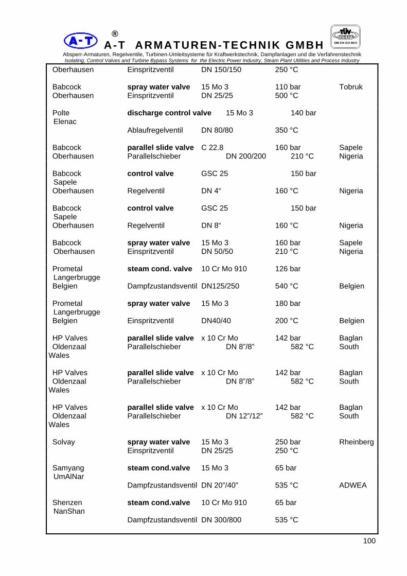
A-T ARMATUREN-TECHNIK GMBH Absperr-Armaturen, Regelventile, Turbinen-Umleitsysteme für Kraftwerkstechnik, Dampfanlagen und die Verfahrenstechnik Isolating, Control Valves and Turbine Bypass Systems for the Electric Power Industry, Steam Plant Utilities and Process Industry
100
®
Oberhausen Einspritzventil DN 150/150 250 °C Babcock spray water valve 15 Mo 3 110 bar Tobruk Oberhausen Einspritzventil DN 25/25 500 °C Polte discharge control valve 15 Mo 3 140 bar
Elenac Ablaufregelventil DN 80/80 350 °C Babcock parallel slide valve C 22.8 160 bar Sapele Oberhausen Parallelschieber DN 200/200 210 °C Nigeria Babcock control valve GSC 25 150 bar
Sapele Oberhausen Regelventil DN 4“ 160 °C Nigeria Babcock control valve GSC 25 150 bar
Sapele Oberhausen Regelventil DN 8“ 160 °C Nigeria Babcock spray water valve 15 Mo 3 160 bar Sapele Oberhausen Einspritzventil DN 50/50 210 °C Nigeria Prometal steam cond. valve 10 Cr Mo 910 126 bar
Langerbrugge Belgien Dampfzustandsventil DN125/250 540 °C Belgien Prometal spray water valve 15 Mo 3 180 bar
Langerbrugge Belgien Einspritzventil DN40/40 200 °C Belgien HP Valves parallel slide valve x 10 Cr Mo 142 bar Baglan Oldenzaal Parallelschieber DN 8”/8” 582 °C South
Wales HP Valves parallel slide valve x 10 Cr Mo 142 bar Baglan Oldenzaal Parallelschieber DN 8”/8” 582 °C South
Wales HP Valves parallel slide valve x 10 Cr Mo 142 bar Baglan Oldenzaal Parallelschieber DN 12”/12” 582 °C South
Wales Solvay spray water valve 15 Mo 3 250 bar Rheinberg Einspritzventil DN 25/25 250 °C Samyang steam cond.valve 15 Mo 3 65 bar
UmAlNar Dampfzustandsventil DN 20”/40” 535 °C ADWEA Shenzen steam cond.valve 10 Cr Mo 910 65 bar
NanShan Dampfzustandsventil DN 300/800 535 °C

A-T ARMATUREN-TECHNIK GMBH Absperr-Armaturen, Regelventile, Turbinen-Umleitsysteme für Kraftwerkstechnik, Dampfanlagen und die Verfahrenstechnik Isolating, Control Valves and Turbine Bypass Systems for the Electric Power Industry, Steam Plant Utilities and Process Industry
101
®
Shenzen spray water.valve 15 Mo 3 85 bar NanShan Einspritzventil DN 65/65 130 °C REFERENZLISTE - HD-Spezial-Armaturen REFERENCE LIST HP-
special valves Customer Product Material/Size design data Plant Kunde Produkt Werkstoff/DN Berechnungsdaten
Anlage Shenzen steam controlvalve WCB 11 bar
NanShan Dampfregelventil DN 300/350 270 °C Babcock parallel slide valve x 20 154 bar HOMS Oberhausen Parallelschieber DN 250/250 545 °C Lybien Thyssen Berlin check valves H II 16 bar
NanShan Rückschlagklappen DN 500 120 °C Thyssen Berlin check valves H II 16 bar
NanShan Rückschlagklappen DN 800 120 °C Thyssen Berlin gate valves 10Cr Mo 910 74 bar
NanShan Schieber DN 300/275 535 °C Prometal gate valve 10 Cr Mo 910 40 bar
Hydro Agri Belgien Keilschieber DN 20“ 530 °C Prometal gate valve 10 Cr Mo 910 40 bar
Hydro Agri Belgien Keilschieber DN 14“ 530 °C Novamat feed water control valve 15 Mo 3 222 bar
Trbovlje Speisewasserregelventil DN 200/200 230 °C Babcock steam control valve 15 Mo 3 140 bar HOMS Oberhausen Dampfregelventil DN 25/80 395 °C Lybien Babcock spray water valve 15 Mo 3 PN 250 HOMS Oberhausen Einspritzventil DN 25/25 Lybien Novamat spray water valve 15 Mo 3 250 bar Oslomej Einspritzventil DN 80/80 250 °C

A-T ARMATUREN-TECHNIK GMBH Absperr-Armaturen, Regelventile, Turbinen-Umleitsysteme für Kraftwerkstechnik, Dampfanlagen und die Verfahrenstechnik Isolating, Control Valves and Turbine Bypass Systems for the Electric Power Industry, Steam Plant Utilities and Process Industry
102
®
Babcock gate valve 15 Mo 3 250 bar ADWEA Oberhausen Keilschieber DN 65/65 180 °C Abu Dhabi Solvay feed water control valve15 Mo 3 200 bar Rheinberg Speisewasserregelventil DN 200/200 185 °C Thyssen Berlin steam control valve 10 Cr Mo 910 175 bar Zhuhei Dampfregelventil DN 80/100 546 °C Thyssen Berlin spray water valve 15 Mo 3 301 bar Zhuhei Einspritzventil DN 2“72“ 350 K Babcock spray water valve 15 Mo 3 226 bar Daura Oberhausen Einspritzventil DN 65/65 200 °C Irak Babcock spray water valve 15 Mo 3 101 bar Daura Oberhausen Einspritzventil DN 25/25 200 °C Irak REFERENZLISTE - HD-Spezial-Armaturen REFERENCE LIST HP-
special valves Customer Product Material/Size design data Plant Kunde Produkt Werkstoff/DN Berechnungsdaten
Anlage Babcock control valve 15 Mo 3 51/11 bar Daura Oberhausen Regelventil DN 150/400 400/350 °C Irak Babcock spray water valve 15 Mo 3 170 bar Daura Oberhausen Einspritzventil DN 40/40 180 °C Irak Babcock spray water valve 10Cr Mo 910 175 bar Daura Oberhausen Einspritzventil DN 50/50 520 °C Irak Babcock gate valve C 22.8 200 bar ADWEA Oberhausen Keilschieber DN 80/80 200 °C Abu Dhabi Babcock spray water valve 15 Mo 3 250 bar ADWEA Oberhausen Einspritzventil DN 80/80 250 °C Abu Dhabi Samyang steam desuperheating cvA182F12 112/10 bar KEPCO,
Korea Dampfumformstation DN250/500 530/250 ° C.
Banwhol PP Deambrosis minimum flow valve Enichem Mindestmengenventil Italy Babcock change over valve bar NEKA PP

A-T ARMATUREN-TECHNIK GMBH Absperr-Armaturen, Regelventile, Turbinen-Umleitsysteme für Kraftwerkstechnik, Dampfanlagen und die Verfahrenstechnik Isolating, Control Valves and Turbine Bypass Systems for the Electric Power Industry, Steam Plant Utilities and Process Industry
103
®
Oberhausen Umschaltventil DN 350/350/300 °C Tavanir, Iran Thyssen Berlin change over valve bar ZhuHou Umschaltventil DN 300/300 °C China Thyssen Berlin quick closing valve bar ZhuHou Schnellschlußventil DN 300/300 °C China Siekmann minimum flow valve bar Prüfstand Mindestmengenventil DN 4”/150 °C Test bed Samyang control valve (1:1000) 10,35 bar
Ulchin Korea Regelventil DN 250/250 93,3 °C
Nuclear PP Novamat spray water valve 15 Mo 3 160 bar
Morava Einspritzventil DN 50/50 350°C Novamat spray water valve 15 Mo 3 170 bar
Morava Einspritzventil DN 50/50 235°C Babcock gate valve 13 CrMo 44 285 bar
Doha West Oberhausen Keilschieber DN 150/125 255 °C Kuwait