A Systems Engineering Approach for Plant Layout …
168
A Systems Engineering Approach for Plant Layout Management & Optimization by Abdulelah Saeed Algarni A thesis submitted to Florida Institute of Technology in partial fulfillment of the requirements for the degree of Master of Science, in Systems Engineering Melbourne, Florida September, 2016
Transcript of A Systems Engineering Approach for Plant Layout …
A Systems Engineering Approach
for Plant Layout Management & Optimization
by
Abdulelah Saeed Algarni
A thesis submitted to
Florida Institute of Technology
in partial fulfillment of the requirements
for the degree of
Master of Science,
in
Systems Engineering
Melbourne, Florida
September, 2016
We the undersigned committee hereby approve the attached thesis, “A Systems
Engineering Approach for Plant Layout Management & Optimization,” by
Abdulelah Saeed Algarni.
_________________________________________________
A. Fabregas, Ph.D.
Major Advisor, Assistant Professor
College of Engineering, Department of Engineering Systems
_________________________________________________
L. Otero, Ph.D.
Committee Member, Associate Professor
College of Engineering, Department of Engineering Systems
_________________________________________________
R. Mesa-Arango, Ph.D.
Committee Member, Assistant Professor
College of Engineering, Department of Civil Engineering
_________________________________________________
M. A. Shaikh, Ph.D.
Professor and Department Head,
College of Engineering, Department of Engineering Systems
iii
Abstract Title: A Systems Engineering Approach for Plant Layout Management & Optimization
Author: Abdulelah Saeed Algarni
Major Advisor: Aldo Fabregas Ariza, Ph.D.
The basis of this paper was to investigate the system engineering
applications on petro-chemical facilities layout designs. This work aims to
facilitate and introduce the application of Facility Layout Problems to industrial
case studies based on system engineering methodologies and performance
measurements. Additionally, an effort was made to present a state-of-the-art
literature review of industrial layout problems that exhibits scarcity of system
engineering role in the design and implementations of industrial Facility Layout
Problems. Facility Layout is one of the demanding large-scale optimization
problems. Upon the completion of this report, we found a great sense of vitality of
system engineering approach together with necessity for more involvement in the
total facilities layout life cycle stages.
iv
Table of Contents List of Keywords ................................................................................................... vii
List of Figures ....................................................................................................... viii
List of Tables ............................................................................................................ x
List of Equations ................................................................................................... xii
List of Abbreviations ........................................................................................... xiii
Acknowledgement .................................................................................................. xv
Dedication ............................................................................................................. xvi
1. Chapter 1 Introduction ........................................................................................ 1 1.1. Background & Motivation ........................................................................... 2
1.2. Purpose & Focus ........................................................................................... 4 1.3. Definition of the Problem ............................................................................. 5
1.4. Assumptions, Limitations & Scope .............................................................. 6 1.5. Scope ............................................................................................................... 7 1.6. Case Study ..................................................................................................... 7
1.6.1. Case 1 .................................................................................................................. 7 1.6.2. Case 2 .................................................................................................................. 9
1.7. Objectives ..................................................................................................... 10 1.7.1. Objective 1 ........................................................................................................ 11 1.7.2. Objective 2 ........................................................................................................ 11
1.8. Methodology and Sample ........................................................................... 12 1.9. Expected Contributions .............................................................................. 13
1.10. Organization of Thesis and Report ......................................................... 13 1.11. Terms, Acronyms and Abbreviations ..................................................... 14
2. Chapter 2 Literature Review ........................................................................... 15
2.1. Overview ...................................................................................................... 16 2.2. Conceptual Framework .............................................................................. 20 2.3. Search Strategy............................................................................................ 20
2.4. Criteria for Selection .................................................................................. 21 2.4.1. The Research Methodology .............................................................................. 22 2.4.2. Data Collection Techniques & Process ............................................................. 23
2.5. System Engineering Approach .................................................................. 25 2.5.1. System Engineering Paradigm .......................................................................... 26 2.5.2. System Engineering Lifecycles ......................................................................... 28 2.5.3. System Engineering Tools & Techniques ......................................................... 29
2.6. Material Handling Systems ........................................................................ 31
v
2.7. Layout Problem (LP) .................................................................................. 32 2.7.1. LP Planning Approach ...................................................................................... 40 2.7.2. LP Modeling & Formulation ............................................................................. 41 2.7.3. LP Constraints & Solution Methodologies ....................................................... 48 2.7.4. LP Algorithms ................................................................................................... 50 2.7.5. LP Evaluation, Performance Measurements & Metrics .................................... 53
2.8. Data Extraction and Results ...................................................................... 60 2.9. Implications, Limitation, Resolutions & Recommendations................... 71 2.10. Literature Review Conclusion ................................................................. 72
3. Chapter 3 Main Case Studies’ Methodology and Results ............................. 74 3.1. Introduction ................................................................................................. 76 3.2. Case Study 1 ................................................................................................ 78
3.2.1. System Concept and Definition ........................................................................ 79 3.2.2. Stakeholders identification and Requirements Analysis ................................... 79 3.2.3. System Design .................................................................................................. 86
3.2.3.1. Customers’ & System Design Requirements ......................................................... 86 3.2.3.2. Engineering Characteristics .................................................................................... 87 3.2.3.3. System Functional analysis .................................................................................... 90 3.2.3.4. System Metrics & Measurement ............................................................................ 91
3.2.4. Proposed Model ................................................................................................ 92 3.2.4.1. Assumptions of the deterministic model ................................................................ 94 3.2.4.2. Parameters and indices ........................................................................................... 95 3.2.4.3. Variables ................................................................................................................. 96 3.2.4.4. Objective function .................................................................................................. 97 3.2.4.5. Mathematical constraints ........................................................................................ 98 3.2.4.6. Computational results ........................................................................................... 100
3.3. Case Study 2 .............................................................................................. 102 3.3.1. System Concept and Definition ...................................................................... 103 3.3.2. Stakeholders identification and Requirements Analysis ................................. 103 3.3.3. System Design ................................................................................................ 109
3.3.3.1. Customers’ & System Design Requirements ....................................................... 109 3.3.3.2. Engineering Characteristics .................................................................................. 110 3.3.3.3. System Functional analysis .................................................................................. 112 3.3.3.4. System Metrics & Measurement .......................................................................... 113
3.3.4. Proposed Model .............................................................................................. 113 3.3.4.1. Assumptions of the deterministic model .............................................................. 113 3.3.4.2. Parameters and indices ......................................................................................... 114 3.3.4.3. Variables ............................................................................................................... 115 3.3.4.4. Objective function ................................................................................................ 115 3.3.4.5. Mathematical constraints ...................................................................................... 115 3.3.4.6. Computational results ........................................................................................... 116
4. Conclusion ......................................................................................................... 119 4.1. Summary .................................................................................................... 119 4.2. Problems arising during the research ..................................................... 119

vi
4.2.1. Problems during data collection ...................................................................... 119 4.2.2. Problems resulting from the research design .................................................. 120
4.3. Recommendations ..................................................................................... 121 4.4. Future Research ........................................................................................ 121
References ............................................................................................................. 122 Generic Bibliography ....................................................................................... 122 FLP Published Articles Bibliography ............................................................ 126
Appendix A Glossary .......................................................................................... 135
Appendix B Literature Review Articles ............................................................ 137
Appendix C programs code ................................................................................ 143
Appendix E AUTOBIOGRAPHICAL REFLECTION ................................... 150
Index ............................................................................ Error! Bookmark not defined.
Vita (Curriculum Vitae) ...................................................................................... 152
vii
List of Keywords Combinatorial Optimization;
Facilities Layout Problem;
System Engineering;
Facility Layout;
Facility Planning;
FLP Models;
Layout;
Layout Optimization;
Literature Review;
Machine Layout;
Manufacturing Facility;
Material Handling;
Metaheuristic;
Optimization Methods;
Plant Layout;
Process Plant Layout;
Quadratic Assignment Problem (QAP);
Simulated Annealing;
Single Row Layout;
Slicing Tree Representation;
Survey of Facility Layout Problems;
Tabu Search;
viii
List of Figures Figure 1. Petrochemical Plant (Secl, 2006) ................................................................ 8
Figure 2. Refinery Process Flow Diagram (Mbeychok, 2007) .................................. 9
Figure 3. Instrumentation of a pump with tank (Con-struct, 2012) ......................... 10
Figure 4 Subsystems of Facility Planning & Management ...................................... 18
Figure 5 SIMILAR Process ...................................................................................... 27
Figure 6 System Engineering Tools & Technique largely adapted from National
Aeronautics and Space Administration, Goldberg (1994) ............................... 30
Figure 7 Layout Problem Theoretical context ......................................................... 32
Figure 8 Facilities Layout Problems in (Continuous representation) block plan with
eight entities ..................................................................................................... 34
Figure 9 Facilities Layout Problems in (Discrete representation) block plan with
eight entities ..................................................................................................... 35
Figure 10. Manufacturing Layouts (Tompkins, 2010, p. 98) ................................... 46
Figure 11 Class Diagram of Metaheuristic Algorithms Adapted from (Fink, Voß, &
Woodruff, 2003, p. 517) ................................................................................... 51
Figure 12. System Design Considerations adapted from (Blanchard & Fabrycky,
2011, p. 38) ...................................................................................................... 54
Figure 13 Hierarchy of Distributed Process Control Systems (Daniele Pugliesi) ... 77
Figure 14 Case Study 1: Chemical Plant with Distillation System .......................... 78
Figure 15 FLP Stakeholders Onion Ring Figure...................................................... 81
Figure 16 Partial Use Case Context Diagram .......................................................... 83
Figure 17 QFD House of Quality for FLP ............................................................... 89
Figure 18 Partial FFBD for FLP .............................................................................. 90
Figure 19 Model Layout........................................................................................... 94
Figure 20 solution to one instance of FLP ............................................................. 101
Figure 21 Case Study 2: Junction Box distribution locations ................................ 102
Figure 22 Instrument Layout Stakeholders Onion Ring Figure ............................. 104
Figure 23 Partial Use Case Context Diagram ........................................................ 106

ix
Figure 24 QFD House of Quality for Instrument Layout ...................................... 111
Figure 25 Partial FFBD for Instrument Layout ..................................................... 112
Figure 26 (Solution) Instruments - Junction Boxes connections ........................... 117
Figure 27 (Decision Var) Instruments' connections to junction boxes .................. 117
Figure 28 parameters for junction box availability to instrument .......................... 118
x
List of Tables
Table I. Layout Modeling Methods adapted from (Tompkins, 2010, pp. 308–341)
.......................................................................................................................... 43
Table II Layout Methods’ advantages and disadvantages (Tompkins, 2010,
pp. 308–341) .................................................................................................... 44
Table III. Process vs. Product Layouts..................................................................... 47
Table IV. Example TPM Priorities table adapted from (Blanchard & Fabrycky,
2011, p. 41) ...................................................................................................... 57
Table V Publications FLP formulations (Sample) ................................................... 61
Table VI FLP Spcecifications (Sample) .................................................................. 63
Table VII FLP Types (Sample) ................................................................................ 64
Table VIII FLP Mathematical Formulation (Sample) ............................................. 65
Table IX FLP Solution Categories (Sample) ........................................................... 66
Table X FLP Solutions (Sample) ............................................................................. 67
Table XI FLP Solutions attributes (Sample) ............................................................ 68
Table XII FLP utlization of System Engineering Tools & Techniques (Sample) ... 70
Table XIII System Elements map to Mathematical Model ...................................... 75
Table XIV System Engineering Process map to Math Model ................................. 75
Table XV FLP Stakeholder Matrix .......................................................................... 81
Table XVI Sample Business Use Cases List ........................................................... 84
Table XVII Sample Use Case Narrative .................................................................. 84
Table XVIII Sample Customers' Requirements for FLP ......................................... 87
Table XIX Sample Sys. Requirements and Design for FLP .................................... 88
Table XX Metrics & Measurement .......................................................................... 91
Table XXI Instrument Layout Stakeholder Matrix ................................................ 105
Table XXII Sample Business Use Cases List ........................................................ 107
Table XXIII Sample Use Case Narrative ............................................................... 107
Table XXIV Sample Customers' Requirements for Instrument Layout ................ 109

xi
Table XXV Sample Sys. Requirements and Design for Instrument Layout.......... 110
Table XXVI Metrics & Measurement.................................................................... 113
xii
List of Equations Equation 1 ................................................................................................................ 56
Equation 2 ................................................................................................................ 56
Equation 3 ................................................................................................................ 56
Equation 4 ................................................................................................................ 92
Equation 5 ................................................................................................................ 93
Equation 6 ................................................................................................................ 97
Constraint 7 .............................................................................................................. 98
Constraint 8 .............................................................................................................. 98
Constraint 9 .............................................................................................................. 98
Constraint 10 ............................................................................................................ 98
Constraint 11 ............................................................................................................ 98
Constraint 12 ............................................................................................................ 99
Constraint 13 ............................................................................................................ 99
Constraint 14 ............................................................................................................ 99
Constraint 15 ............................................................................................................ 99
Constraint 16 ............................................................................................................ 99
Constraint 17 .......................................................................................................... 100
Constraint 18 .......................................................................................................... 100
Constraint 19 .......................................................................................................... 100
Constraint 20 .......................................................................................................... 100
Equation 21 ............................................................................................................ 115
Constraint 22 .......................................................................................................... 115
Constraint 23 .......................................................................................................... 116
Constraint 24 .......................................................................................................... 116
Constraint 25 .......................................................................................................... 116
xiii
List of Abbreviations ABC: Artificial Bee Colony
ARC: Activity Relationship Chart
AFSA: Artificial Fish Swarm Algorithm
AHP: Analytic Hierarchy Process
ALDEP: Automated layout design program
ANSI: American National Standards Institute
API: Application Program Interface
CLP: Cell Location Problem
CORELAP: Computerized relationship layout planning
CRAFT: Computerized Relative Allocation of Facilities Technique
FFBD: Functional Flow Block Diagram
FLP: Facility Layout Problem
FLPSE: Facility Layout Problem System Engineering
FMS: Flexible Manufacturing System
GA: Genetic Algorithm
GT: Graph Theory
GUI: Graphical User Interface
KPP: Key Performance Parameters
LAP: Linear Assignment Problem
LOGIC: Layout Optimization with Guillotine Induced Cuts
LP: Linear Programming
MA: Memetic Algorithm
MCRAFT: MICRO-Computerized Relative Allocation of Facilities
Technique
MIP: Mixed Integer Programming
MO: Multi-Objective
MOE: Measurement of Effectiveness
xiv
MOP: Measurement of Performance
MP: Mathematical Programming
MTS: Material Handling System
MULTIPLE: Multi-floor Plant Layout Evaluation
NLP: Non-Linear Programming
OPM: Organizational Performance Measurement
PCS: Process Control System
PFD: Process Flow Diagram
P&ID: Piping and Instrumentation Diagram
PPM: Project Performance Measurement
QAP: Quadratic Assignment Problem
QFD: Quality Function Deployment (House of Quality)
SA: Simulated Annealing
SE: System Engineering
SER: Smallest Enclosing Rectangle
SFC: Space-Filling Curve
SLP: Systematic Layout Planning
TPM: Technical Performance Measurement
UML: Unified Modeling Language

xv
Acknowledgement Thank you, Lord, for always being there for me.
There are a number of people without whom this thesis might not have been
written, and to whom I am greatly indebted. First and foremost, enormous gratitude
is due to my parents. Thank you, I am here because of you. My mother, sisters, and
brothers, your presence makes my life a pleasant experience. My wife and children
deserve my wholehearted thanks as well, thank you for understanding and
encouragement in my many, many moments of weakness and crisis, thank you for
taking the blows and giving me a chance to thrive.
I would like to sincerely and truly express my deepest gratitude to my
advisor and my committee chairman, Dr. Fabregas, for his guidance, mentorship,
reflecting, inspiring, motivating, and support throughout this study, and especially
for his confidence in me, not only bounded to this thesis but moreover to life. A
special thanks to Dr. Otero and Dr. Mesa-Arango for serving as members of my
thesis committee, who were more than generous with their expertise and precious
time.
I am grateful too for the support from my sponsoring company Saudi
Aramco. Finally, thanks to all my friends. You all are always in my mind without
listing all the names. At last, I am very fortunate to have performed my graduate
work at a university as collaborative as Florida Institute of Technology; therefore, I
would like to express my appreciation to the institution faculty especially those of
Engineering Systems department.
This thesis was a wondrous journey

xvi
Dedication
: الإهداء
.فيشفع عسى ان يكون من العلم الذي ينفع الكريم هخالصاً لوجه لله
.رحمتهواسع داد هذه الرسالة تغمدهما الله بن رحلا وقت إعوجدتي اللذيلى والدي إو
وا قبورهم بدؤوب العمل وسوا تربتهم بماء نقي يرتشفون منه يوم العطش الأكبر, إلى من جربنا إلى من بن
من بعدهم وجع المكان تركوا في كل زاوية ذكرى الساكنون بكل أروقة الفؤاد الراحلون !!
This is dedicated to:
My father (Saeed) and grandmother (Haaya) who passed away during
my writing of this thesis. …….Thanks, Dad. …….. Thanks, Grandma.
My family: my beloved mother (Nora), my sisters (Haaya, Jaafela,
Hayfa, Naajela, & Ghaida) and my brothers (Mardhi, Mohammad,
Sultan, Abdulghani, Abdulrahman, Faisal).
My wife (Eman) and my children (Alfaisal & Leen), for their endless
patience, love, and care.
My major advisor Dr. Aldo Fabregas Ariza.
You, as a reader.
1
1. Chapter 1 Introduction
The report provides its readership with a problem-oriented access to the
process, methods, techniques and tools in the field of facilities layout planning and
design. The audience will be presented with background information in facilities
layout field, reviewing problem formulations and models along with the state-of-
the-art algorithms and solutions techniques.
The first part of this introduction review will introduce a brief background
on the topic of facilities layout problem. The two case studies will illuminate the
usefulness and importance of such topic, though the development of such use cases
will be averted later on to be elaborated in the main thesis work.
2
1.1. Background & Motivation
Over 25% of U.S. businesses investments (a trillion dollars per year for last
five years in the last decade) was spent on new structures, as per the U.S Census.
In addition, planning for new facilities has cost around 8% of US annual GNP since
1995. (Tompkins, 2010, p. 9). For industrial facilities organization, accurate and
detailed intelligence about the performance, development, operation and costs of its
facilities layout is a strategic asset. Typical design period for facilities spans 5-10
years with space requirement being the dominant factors in the design
specifications. (Tompkins, 2010, p. 119). Controlling the risks, costs, and defects
of services, products, and projects are becoming an essential part of today's global
competition management strategies. Industrial facilities impose large-scale
magnitude of such risks and costs during the whole facilities lifecycles. The
organization is responsible for all the incurred costs for facilities lifecycle phases
including design, construction, operation, and maintenance. In order to control
such costs and improve its profits, the organization must be able to control and
sustain the facilities layout to carry out its business to the maximum efficiency. In
addition, with environmental, health, safety and energy constraints, it becomes
important that designing facilities layout should take into considerations :
Sustainability engineering, Resilience engineering, Security engineering, Safety
engineering, Value engineering, Reliability, Maintainability, Availability, Logistic
engineering, supply chain management, PHS&T (i.e. Packaging, handling, storage,
and transportation), waste management, ...etc.
3
Apart from designing and developing of a system as in the case of industrial
facility layout, System Engineering applies well-proven tools and methodologies
across the system lifecycles that ensure proper integration of all involved tasks
including project, design, and operation-related functions with efficient cost
management and high-quality process. It is worth mentioning that there are several
literature reviews related to the layout problems, and the most general and recent
one was back in 2007, the rest are either specific layout surveys or older reviews.
(Drira, Pierreval, & Hajri-Gabouj, 2007). We are motivated to undertake this
exploratory study by complete unified study for the subject of facilities layout from
System Engineering perspective. Alternative layout arrangements do raise several
questions like:
What is the appropriate techniques and methodologies to be used by
organizations for facilities layout problem?
What is the recommended algorithms or modeling for the facilities
layout planning? Moreover, why?
How can such techniques help in case of new facilities vs. existing
facilities modernizations petition?
The answers to such questions may help organizations to make better
decisions about layout planning and management.
4
1.2. Purpose & Focus
In recent years, many contemporary capital projects have had cost overruns
and poor plant performance. In this study, we aimed at how organizations can
apply the system engineering approach and the ways they seek to enhance overall
facilities layout while maintaining the costs and schedules baselines. The purpose
of this report is to promote the process of system engineering approach to facilities
layout management and to apply layout optimization on industrial cases.
We begin with the assumption that organizations have considerations for all
concerning and competitive goals and objectives that result in different layouts
scenarios producing different optimization index values. In other words, we
assume with some degree of confidence, that organizations have interests in layout
rearrangements for higher design and operation efficiency. Using the oil & gas
industrial facilities as a case study, this research will explore the innovative
possibility to harness the benefits of the system engineering approach specifically
on the facilities layout design. Our focus is on the case of lifecycles of design and
management of equipment and machines layouts in an industrial plant. The
findings are based on systematic approach along with modeling of different real-
world scenarios.
5
1.3. Definition of the Problem
Plant layout deals with the arrangement of the physical facilities inside the
plant site. Such problems are also known as Facilities Layout Problems (FLP)
(Drira et al., 2007, p. 255). Layout problems cover several subproblems including
but not limited to space allocation, internetworking, optimization, and decision
support system among others. The problems related to plant layout are generally
observed because of the various developments that occur simultaneously. These
developments include the adoption of the new standards of safety, changes in the
design of the product, the decision to set up a new plant, introducing a new product,
withdrawing the various obsolete facilities, etc. Facility layout design has been a
complex problem facing wide industrial sectors for the last decades. By some
estimations, Up to 50% of operating costs are due to facility material handling.
(Tompkins, 2010, p. 10).
Plant layout is very complex in nature; because it involves concepts relating
to such fields as engineering, architecture, economics and business management.
Understanding the significance of layout and its association with operational costs
among others, applying a well-established system-wide engineering methodology
becomes of compelling importance to tackle such expanding complexity
6
1.4. Assumptions, Limitations & Scope
In our initial literature review being reported here, we analyzed the trends of
layout problems from System Engineering perspective. We indicated the directions
of layout problems issues and solutions methodologies. We focused our literature
investigations to the physical industrial facilities and related fields. Also, this
study limits to the layout and location issues with occasional indications of related
issues like material handling systems, transportations, office environment hygiene,
etc. Facilities layout deals with micro-elements while its location deals with
macro-elements. (Tompkins, 2010, p. 7).
In this treatise, our case studies will be restricted to static facility layout
excluding dynamic aspects of facility layout since we feel promoting SE to static
layout will pave the road for future investigation in the dynamic ones. We should
indicate that congestion in material handling and transportation, as well as
capacitated facilities cases, are not taken into account. In addition, only
deterministic requirements and specifications are being investigated in those case
studies. In such situations, we are inclined to deal at large with a single-floor
facilities, known as planner layout or two-dimensional space layout. Most of US
facilities are single-floor facilities. (Tompkins, 2010, p. 351)
7
1.5. Scope
Facilities layout exhibits the constituent of any projects namely, scope or
objectives, timeline or schedule, and budgets. We are presenting here the published
academic works, excluding commercial packages due to lack of full access to most
of the packages in order to fairly represent them. In addition, most of the literature
algorithms are off-line algorithms, and we will maintain the same trend.
In our efforts here, we evaluate the resulted layout based on initial standard
requirements and specifications for specific defined goals and objectives. Such
goals might be evaluated with different weightings based on particular industry.
Such variations can be explored with simulations of the results presented in this
report.
1.6. Case Study
The System Engineering framework approach is exhibited for two industrial
cases.
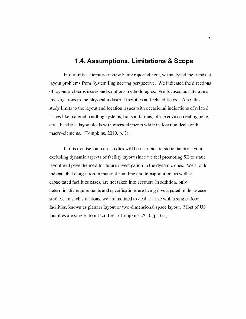
1.6.1. Case 1
The layout of oil refineries and gas plant with distillation columns will be
adopted as a case study to demonstrate the proposed layout approach.
8
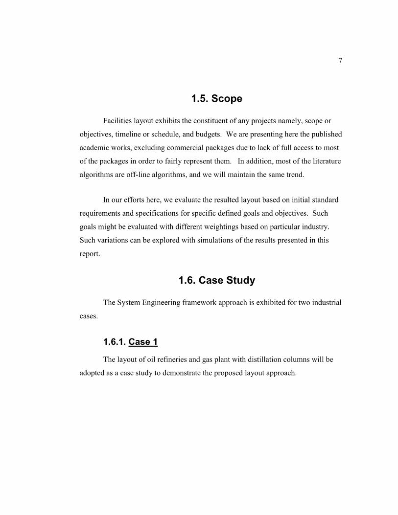
Typical plant structures are shown in Figure 1, while the process flow
diagram is shown in Figure 2. For instance, in the gas distillation process, light
ends mixes of natural gas liquids are separated to butane, propane, and ethane in
this sequential order or reverse. The process involves refinement of overhead
gasses in order to reach certain gas composition purity. Heat exchanger equipment
(bottom reboilers and overhead finned fans with chilling compressors) are used to
control the heat.
Figure 1. Petrochemical Plant (Secl, 2006)
9
Figure 2. Refinery Process Flow Diagram (Mbeychok, 2007)
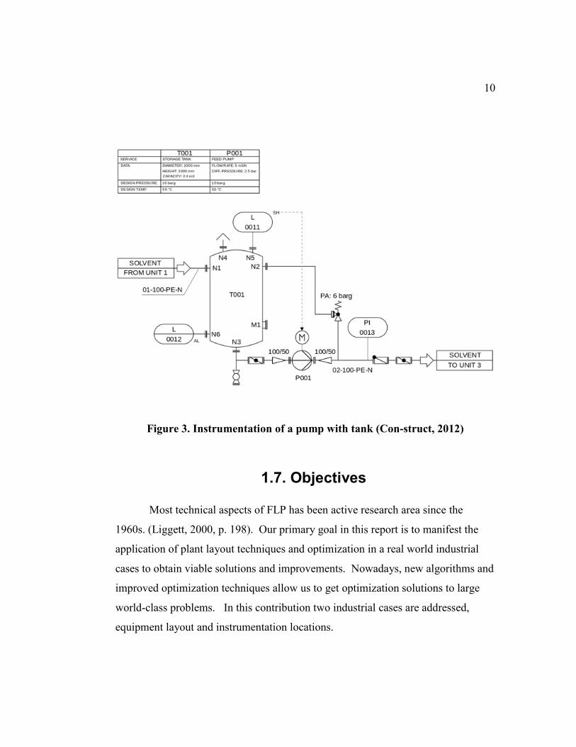
1.6.2. Case 2
The layout of control systems and instrumentation in a typical industrial
facilities. Such problem can involve the design of control rooms, control systems
cabinets, control systems network topologies, or plant-wide instrumentation
locations. In the second case, we will focus our investigating on the
instrumentation Junction Boxes locations allocation which is also known as a set
covering problem or total covering problem. See example of such case in Figure 3.
10
Figure 3. Instrumentation of a pump with tank (Con-struct, 2012)
1.7. Objectives
Most technical aspects of FLP has been active research area since the
1960s. (Liggett, 2000, p. 198). Our primary goal in this report is to manifest the
application of plant layout techniques and optimization in a real world industrial
cases to obtain viable solutions and improvements. Nowadays, new algorithms and
improved optimization techniques allow us to get optimization solutions to large
world-class problems. In this contribution two industrial cases are addressed,
equipment layout and instrumentation locations.
11
In addition, part of our goals in this paper is to be a first step for
understanding such potentiality and draft a conceptual design for the development
of Facility Layout Problem System Engineering (FLPSE) framework and tools.
The purpose here is to take further consideration in the integration of the System
Engineering approach with the FLP to result in a constructive composite. For such
reason, we chose the phrase “layout management” to encompass the layout
planning, strategy and design processes.
The research goals summarized as:
1.7.1. Objective 1
A showcase of an application of facilities layout planning and optimization
for real-world petrochemical industrial cases is presented. In addition, performance
metrics for facilities layout will be explored and characterized for optimization and
efficiency layout purposes.
1.7.2. Objective 2
In order to adapt System Engineering in facilities layout planning, this
paper's objective is to build a bridge between facilities layout design and system
engineering approach and techniques; and hence, to lay the foundations for a
modern facilities layout System Engineering applications. We introduce a
planning framework that unifies facilities layout planning and management with
System Engineering framework.
12
Our long-term goal is to promote and derive a better integration for
applying System Engineering framework to the facility layout problems. The result
of such outcome would then pave the road to attempt developing model based
System Engineering MBSE in FLP.
1.8. Methodology and Sample
We introduced a literature review and survey for most of the layout-related
publications in the last decade. Essential concepts of facilities layout problems
were explained. We then analyzed the research trends in layout problems in
general. Such findings had been analyzed for trends, limitations, applications
areas, etc. Literature review findings will direct our basis for the layout
implementations methods to be recommended in the later chapters.
This survey had covered over (100) peer-reviewed articles and publications.
Application fields include abstract problems, chemical industry, warehousing,
power plants, etc. Traditional algorithms and models include heuristics,
metaheuristics, and artificial intelligence. Significant limitations of most situations
where: problem formulations, exact solutions, real word constraints, and other
facilities fields like scheduling and production planning. Also, any use of System
Engineering approach or tools had been reported for each article under the study.
13
1.9. Expected Contributions
Effective FLP Layout planning and optimization can mitigate potential risks
through the development of detailed and specific layout model and scope
definition. Additionally, a review of the literature related to the application of SE
for FLPs does not appear to have been documented and is a contribution of this
research. The author believes that organizations find great value in utilizing the SE
framework for the FLP.
1.10. Organization of Thesis and Report
This thesis is organized into four chapters. It also includes appendices that
provide information on terminologies, algorithms, as well as a detailed list of
survey articles used for literature review statistics.
Chapter 1 includes an introduction to the research topic, research objectives,
and case studies definitions. Chapter 2 provides a semi-comprehensive survey on
published works in the last decade to date related to the general facilities layout
problem topics. The thesis System Engineering methodology for FLP is addressed
in Chapter 3 with illustrations of the implementation of layout models on the case
studies where results are presented. Finally, Chapter 4 closes with our conclusions,
recommendations, and future research suggestions.
14
1.11. Terms, Acronyms and Abbreviations
Several vocabularies are describing the common aspect of the facility layout
problem domain. Some of such words are used exchangeable with different
groupings and relative combinations of these words:
1. [industrial OR factory OR plant OR facility OR floor OR building
OR space OR ” ”] +
2. [Layout] +
3. [design OR plan OR planning OR strategy OR problem OR “ “] +
4. [optimization OR allocation OR model OR management OR
algorithm OR “ “]
For instance, Facility Layout Problem (a.k.a. FLP) might frequently be
used. However, we see the most central keyword that captures the essence of the
problem is the word “LAYOUT.” In this report, we will employ the several
terminologies; we refer the reader to the front matter and Appendix A for a list of
all acronyms, abbreviations, and definitions used.
15
2. Chapter 2 Literature Review
The purpose of this literature review is to establish the importance of the
facilities layout topic in System Engineering field. Also, this literature is to provide
a background review to help apprehend the layout problem’s domain. Also, this
study is to establish and develop knowledge with recent and up-to-date researches.
Facility Layouts have been researched for more than a half-century (Benjaafar,
Heragu, & Irani, 2002).
This chapter provides a preview of the research on facilities layout through
system engineering approach. Since few has been published on the treatise of FLP
System Engineering, we will aim to analyses and treat the traditional engineering
approach of FLP via System Engineering approach. In general, we envision more
adoption of system engineering approach in FLP domain that would yield gains in
the facilities planning, projects, and management. The main body of this literature
review is presented in the second half of this chapter.
16
First, the search strategy for this literature is explained. Then, the System
Engineering approach is illustrated with the focus of its applicability to the
facilities layout problem. After that, a brief introduction to Material Handling
System and its relationship with the layout problems. The layout problem is then
thoroughly described and analyzed with the respect to its formulation models,
solution methodologies, and algorithms implementations. Likewise, the evaluation
of layout solutions will be presented to be the basis of performance metrics. In
addition, the main contribution of this chapter will be expressed as summarizing
table and trending graphics of past research criteria (which is the unique aspect of
this literature review) in the light of applying the System Engineering framework
on all the facility layout life cycles. The rest of this part will discuss the findings
and results and then finalize with the conclusion of the literature review.
2.1. Overview
The subject of FLP is rich in the literature, and several reviews have been
published during the last century and at the turn of this century; at this stage, it
must be clear that this chapter's goal is not to provide complete coverage to all FLP
related publications nor to provide very narrower reviews either. The main aim
here is to distil the most proven models, solutions, and algorithms as well as to
foretell the future trends. This literature review will provide the reader with an
adequate insight into recent research trends concerning the layout problem and the
current state of knowledge.
17
The intent here is to make a merged overview of System Engineering and
facilities layout concepts that seeks to consolidate typical layout problems
approaches into a Systems Engineering framework. The theme of this literature
study will be a combination of chronological (i.e. nearly the last decade),
methodological (such as approaches and System Engineering framework), and
conceptual aspects (namely, layout problem models, solutions, and algorithms).
As far as we know, this study is the most recent survey which is focusing on
the approach and framework used for modeling and solving specifically System
Engineering approach, and at the same time is not restricted to any layout type
problem; yet is not entirely exhaustive (Drira et al., 2007). Tompkins addressed the
facility planning at large as an integral activity of Supply Chain management
excellence framework. (Tompkins, 2010, p. 8).
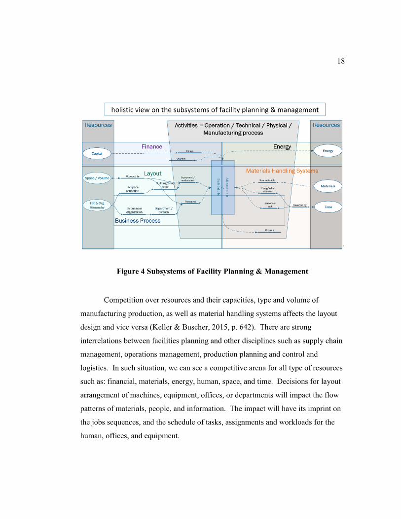
We visualize Facilities layout as an integrated domain of any manufacturing
system as shown in Figure 4. Each domain is a separate field that interacts with the
other domains. Facilities layout consists predominantly of space allocation, coupled
with networking, transportation, material handling systems, activities scheduling,
and resource allocations.
18
Figure 4 Subsystems of Facility Planning & Management
Competition over resources and their capacities, type and volume of
manufacturing production, as well as material handling systems affects the layout
design and vice versa (Keller & Buscher, 2015, p. 642). There are strong
interrelations between facilities planning and other disciplines such as supply chain
management, operations management, production planning and control and
logistics. In such situation, we can see a competitive arena for all type of resources
such as: financial, materials, energy, human, space, and time. Decisions for layout
arrangement of machines, equipment, offices, or departments will impact the flow
patterns of materials, people, and information. The impact will have its imprint on
the jobs sequences, and the schedule of tasks, assignments and workloads for the
human, offices, and equipment.
19
These subsystems’ interactions are inseparable since flows and schedules
are dependent on the types of the layout while at the same time, the layout will be
dependent on flow and schedule of activities either technical, operational activities
or business workflow. Hence, driving layout to optimality based on the proposed
activities schedules and flow types and frequencies might lead to sub-optimality in
operational schedule or flow and vice versa. Such problem is known as a multi-
level or hierarchical optimization (or bi-level in this case) in which the constraints
of the upper objective functions are other lower optimization problems which in
turns have constraints as other optimization problems or as the initial optimization
problems.
Total comprehensive optimization of FLP would involve multi-level
optimization of all resources, space, time, materials, etc. Figure 4. Shows most
influential resources on the facilities planning. Each resource allocation and
formulations are full-fledged optimization field. For example, scheduling of
activities and job sequences are concerning the time resource, while space resource
is handled by packing, storage, layout and locations problems. Such complexity
drives us to foresee System Engineering as a strong candidate approach to handle
such complexity. Our research her is limited to the layout case and meanwhile
recognizes the interdependence of other resources on the whole facilities planning.
Recognition of such dependency will be in the form of choosing mathematical
programming (seen in later chapters) as a modeling schemes since it allows other
researchers to integrate their resource constraints into our model and vice versa.
20
2.2. Conceptual Framework
Our approach is mainly information prominent with occasional author-
prominent for significant contributions to the field of facilities layout planning.
This literature review is not meant to be a fully exhaustive survey, yet it spans a
long-term of published works on the subject of layout planning. Latest FLP survey
indicates a constant progress of publishing researches related to layout planning in
several fields.
We look, through literature review and based on system engineering
prominent tools, techniques, and life-cycles, to assert the general approach that
researchers use to plan and manage facilities layouts.
2.3. Search Strategy
Facilities layouts start with modeling of the problem, mathematical
formulations, solutions approach, algorithms design, simulations and evaluations.
During the articles analysis, this literature review will investigate the spectrum of
such articles based on the several characteristics which will be summarized in a
table (Sec. 2.7). Those characteristics include: modeling and formulation,
constraints, solutions, algorithms, application areas, frameworks, and System
Engineering tools.
21
In our research methodology here in this literature review, we introduce a
latest analysis about the layout problems in approximately the last decade. First, we
will present the System Engineering framework and approach in general. We will
also briefly indicate the key stages in the System Engineering lifecycles. Then, we
will selectively exemplify several System Engineering tools and techniques that are
being used or being suggested to be used for the facilities layout management.
Second, we will portray the selection criteria for the published articles subject to
this survey. Third, we illustrate the layout problems including the problem
modeling, solution approaches, algorithm used, and performance metrics. Fourth,
information collected from the articles will be presented in a tabular format for
further analysis in the next section. After that, the limitations of approaches being
used in such published works will be analogized to the System Engineering
framework. Finally, the literature review conclusion will be presented.
2.4. Criteria for Selection
This literature review will highlight the most important works over the last
decade that have treated FPL-related issues. Hence, any System Engineering
methodologies & Tools will be highlighted whenever used or presented in all the
papers under this study.
22
The findings are based on peer-reviewed articles of a major publishers for
nearly the last decade, since 2000, on the subjects of facilities layout. We are
presenting what we observe as a representative and diversified subset of layout
problem that has been published to date. Note that the survey study will not
discuss the details of all listed publications instead will highlight major trends and
efforts in such publications.
2.4.1. The Research Methodology
This will be the quantitative part of the literature review that is based on
analyzing the data collected from the academic articles. We hope to show the
research trends in this field (FLP) and how much degree the System Engineering
has ever been adopted. Since this literature will gather such data, any previous
surveys or literature review works will be excluded allowing only the original
works to be included in the study, except for reference or related information.
For the publications to be considered in this study, each publication must be
strongly related to sizable physical facilities and must contain at least two of the
following Layout elements:
Layout model
Solutions methods
Algorithms
Framework
23
2.4.2. Data Collection Techniques & Process
In their survey, the authors (Drira et al.) have listed many factors
determining the aspects of representing FLP and then categorized such factors in a
tree graph. among such factors are : "manufacturing systems, facility shapes,
layout configurations devices, flow movement, material handling systems, layout
evolution, layout formulations, type of data, objectives, constraints, resolution
approaches". We adapted most of such factors into tables summarizing the data
collection. (Drira et al., 2007, pp. 256–257).
For each publication, we will indicate the following data:
Problem model formulation
Objectives
Constraints
Layout representation
Material handling layout type
Facility production layout type
Mathematical model formulation
Layout evolution
Solution categories and methods.
24
Algorithm categories and methods.
Application area.
Metrics.
Framework.
System Engineering Tools & Technique if any.
The analysis for data to be collected from the published works is generally
quantitative in nature. Once the review studies will be completed, the data will be
transcribed and organized. General trends in number of publications with respect
to several data type mentioned earlier will be reported for the target period. Also,
Trends in chronological order will be sketched; such trends will be reported
annually.
25
2.5. System Engineering Approach
Traditional engineering approach has been used with facility layout
planning which includes: problem definition, problem analysis, space requirements,
alternative evaluations, solutions approved, and then design implementation.
(Tompkins, 2010, pp. 14–15). Other approaches for facilities layout include
Facilities Planning Process with 10 steps and Wining Facilities Planning Process
with 12 steps. (Tompkins, 2010, p. 18). Facilities layout planning and management
is a complex area involving several engineering and technical management
disciplines. Resource requirements, as space, time, energy, materials, and finance,
by such disciplines invite more competition and more conflicts. Complex systems
such as facilities layout imposes heavy strain on the traditional management and
engineering design approaches (See Figure 4).
On the other hand, System Engineering evolves as a comprehensive and
integrated approach to handle such complexity. (Yasseri, 2014, p. 93). Systems
Engineering discipline covers two perspectives: managerial and technical. The
managerial part is concerned about the enterprise strategy and the whole system
lifecycles costs and projects implementations, while the technical part is concerned
with the process of planning, designing operation and efficiency of the system.
(Tiusanen, 2015, p. 1764). For complex systems, the process of logistics, team
management, requirements, reliabilities, risk management, optimization and
performance metrics gets more intricate. System Engineering is equipped with
theories and foundations to cover and handle such situations. Also, System
Engineering utilizes the modeling and simulations tools to sustain the system
development stages in the whole lifecycles (Tiusanen, 2015, p. 1765).
26
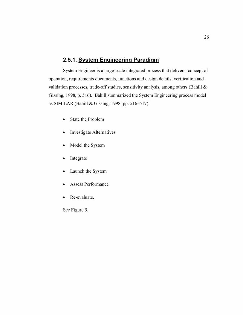
2.5.1. System Engineering Paradigm
System Engineer is a large-scale integrated process that delivers: concept of
operation, requirements documents, functions and design details, verification and
validation processes, trade-off studies, sensitivity analysis, among others (Bahill &
Gissing, 1998, p. 516). Bahill summarized the System Engineering process model
as SIMILAR (Bahill & Gissing, 1998, pp. 516–517):
State the Problem
Investigate Alternatives
Model the System
Integrate
Launch the System
Assess Performance
Re-evaluate.
See Figure 5.
27
Figure 5 SIMILAR Process
Due to long-term life cycles of the facilities and the substantial impact of
early plans during the design stage, adoption of System Engineering approach is
essential to the success of the manufacturing facilities owing such success to its
cost-effective management of the design complexity parameters. Systems
Engineering is a field of Engineering that has a long history of application to
complex technical systems ("Systems Engineering Approach," 2012, p. 19).
System Engineering process aims to help to bring sophisticated and functioning
facilities into being.
IntegrateModel the
System
Investigate
Alternatives
State the
problem
Launch the
System
Assess
Performance
Re-evaluate
Time Line
The SIMILAR Process
Customer
RequirementsOutputs
28
2.5.2. System Engineering Lifecycles
The System Engineering life cycle process is meant to embrace the internal
lifecycles of the product, project or service throughout the whole system lifecycle.
Such system lifecycles include the conceptual design, system design, and
subsystem or component design. The system lifecycle includes four lifecycles:
product or service, production, support and then decomposition lifecycles
(Blanchard & Fabrycky, 2011, pp. 29–31). System Engineering’s Key life-cycle
stages as per INCOSE System Engineering Handbook include concept,
requirements, development, implementation, operation, maintenance, and
retirement. Such lifecycle stages are consistent with the international System
Engineering standards ISO/IEC 15288: (Walden, Roedler, Forsberg, Hamelin, &
Shortell, 2015, p. 2).
1. Concept and Trade Studies = S
2. Requirements = I
3. Design and development = M
4. Implementation and optimization = I
5. Operation = L
6. Maintenance = A
7. Retirement = R
29
2.5.3. System Engineering Tools & Techniques
Systems Tools are primarily concerned with generating and managing
information. Systems Engineering requires a toolbox of “Systems Tools” that will
allow the team to understand customer requirements, explore design options,
optimize designs, make designs robust, validate the design and realize system
designs. The quality of applying System Engineering solution is highly related to
the successful utilization of System Engineering tools and techniques (Blanchard
& Fabrycky, 2011, p. 117). The tools and techniques proposed in this section find
possibly useful applications on FPL domain. Holistic and collective use of several
tools and techniques will enhance the pursued FPLSE (Facilities Layout Problem
System Engineering) optimality. FLPSE developer needs to know those tools to
decide which ones to use for a higher quality result. The FLPSE developer can refer
to the reference section at the end of this report for more details explanation of the
tools and techniques mentioned here.
30
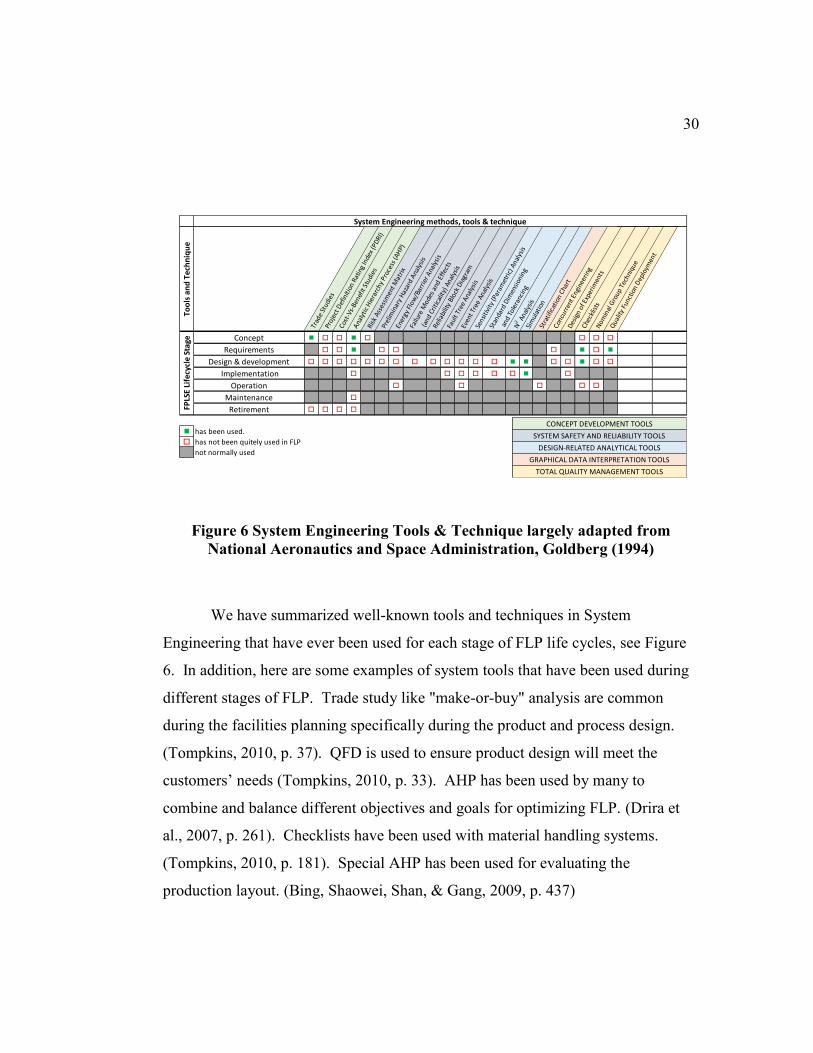
Figure 6 System Engineering Tools & Technique largely adapted from
National Aeronautics and Space Administration, Goldberg (1994)
We have summarized well-known tools and techniques in System
Engineering that have ever been used for each stage of FLP life cycles, see Figure
6. In addition, here are some examples of system tools that have been used during
different stages of FLP. Trade study like "make-or-buy" analysis are common
during the facilities planning specifically during the product and process design.
(Tompkins, 2010, p. 37). QFD is used to ensure product design will meet the
customers’ needs (Tompkins, 2010, p. 33). AHP has been used by many to
combine and balance different objectives and goals for optimizing FLP. (Drira et
al., 2007, p. 261). Checklists have been used with material handling systems.
(Tompkins, 2010, p. 181). Special AHP has been used for evaluating the
production layout. (Bing, Shaowei, Shan, & Gang, 2009, p. 437)
System Engineering methods, tools & technique
Too
ls a
nd
Tec
hn
iqu
e
Trad
e St
udie
s Pr
ojec
t Def
initi
on R
atin
g In
dex
(PD
RI)
Cost
-Vs-
Bene
fit S
tudi
es
Ana
lyti
c H
iera
rchy
Pro
cess
(AH
P)
Risk
Ass
essm
ent M
atrix
Prel
imin
ary
Haz
ard
Ana
lysi
s
Ener
gy F
low
/Bar
rier
Ana
lysi
s
Failu
re M
odes
and
Eff
ects
(and
Cri
tical
ity) A
naly
sis
Relia
bilit
y Bl
ock
Dia
gram
Faul
t Tre
e A
naly
sis
Even
t Tre
e An
alys
is
Sens
itiv
ity
(Par
amet
ric)
Ana
lysi
s
Stan
dard
Dim
ensi
onin
g
and
Tol
eran
cing
N2 A
naly
sis
Sim
ulat
ion
Stra
tific
atio
n Ch
art
Conc
urre
nt E
ngin
eeri
ng
Des
ign
of E
xper
imen
ts
Chec
klis
tsN
omin
al G
roup
Tec
hniq
ue
Qua
lity
Func
tion
Dep
loym
ent
Concept n o o n o o o o
Requirements o o n o o o n o n
Design & development o o o o o o o o o o o o o n n o o n o o
Implementation o o o o o o n o
Operation o o o o o
Maintenance o
Retirement o o o o
n has been used.
o has not been quitely used in FLP
not normally used
FPLS
E Li
fecy
cle
Sta
ge
CONCEPT DEVELOPMENT TOOLS
SYSTEM SAFETY AND RELIABILITY TOOLS
DESIGN-RELATED ANALYTICAL TOOLS
GRAPHICAL DATA INTERPRETATION TOOLS
TOTAL QUALITY MANAGEMENT TOOLS
31
2.6. Material Handling Systems
A material system is an integrated system involving such activities as
handling, storing, and controlling of materials. The primary objective of using a
material handling system (MTS) is to ensure that the material in the right amount is
safely delivered to the desired destination at the right time with minimum cost. A
material handling system ensures the delivery of material to the appropriate
locations. (Drira et al., 2007, p. 256). Up to 70% of production costs are due to
material handling costs. (Tompkins, 2010, p. 176).
We cannot eliminate nor ignore the interrelationship with MTS. However,
we will limit any discussion to a bare minimum and only include the direct impact
elements of MTS on the layout as much as possible without rendering the problem
into pure theoretical or unrealistic example.
During the facility design, the question arises of which comes first material
handling systems or facilities layout (Tompkins, 2010, p. 293) Layout, and material
handling systems are inter-dependent design problems. (Drira et al., 2007, p. 256).
Material handling system and facilities layout problem are highly integrated.
(Tompkins, 2010, p. 175).
32
The simultaneous or concurrent design of layout and MTS is preferred;
however, this will lead to the bi-level optimization problem. (Kheirkhah, Navidi, &
Messi Bidgoli, 2015, p. 396). Since manufacturing is a value-added operation and
move materials around does not add any value, the simple rule for material
handling is the less (cost, time, labor, etc.) the better. Layout setup will determine
the pattern of the flow materials, and the physical inter-relationship of activities.
(Tompkins, 2010, p. 292). Handling systems deal with different types of handling
such as materials, personnel, information and equipment with materials being the
most widely treated aspect. (Tompkins, 2010, p. 7). Different design basis result
into diverse performance for different objectives (Asef-Vaziri & Laporte, 2005,
p. 5).
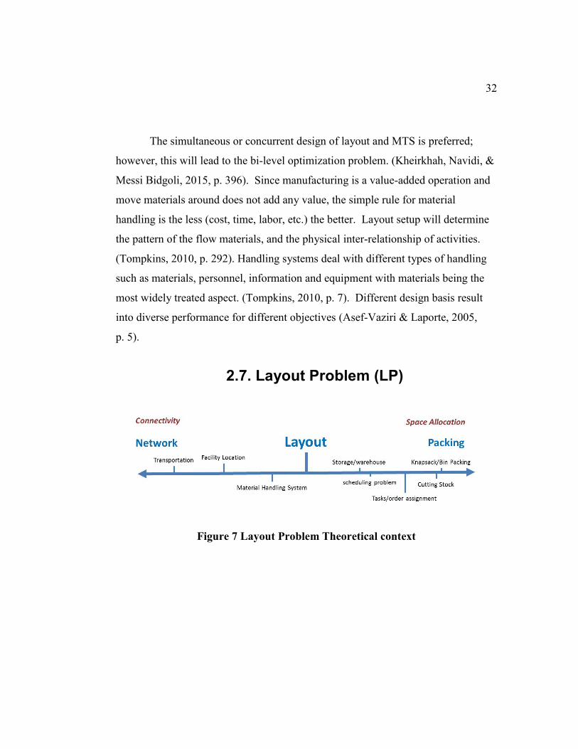
2.7. Layout Problem (LP)
Figure 7 Layout Problem Theoretical context
33
The placement of the facilities in the plant area, often referred to as
‘‘facility layout problem’’ (Drira et al., 2007, p. 255). Tompkins defined the
facility planning as “determines how an activity’s fixed assets best support
achieving the activity’s objective” with "facility location refers to its placement
with respect to customers, suppliers, and other interfacing facilities." (Tompkins,
2010, p. 6). Another definition is “Facility layout is the planning, designing, and
physical arrangement of processing and support areas within a facility”. The main
concern of the layout is to achieve the operation goals while optimizing the
resource utilization. Complexity rises from such competing goals and intersecting
constraints. Layout planning starts with location, then outline layout (called block
or macro units), then detail layout (called populated units), then implementation
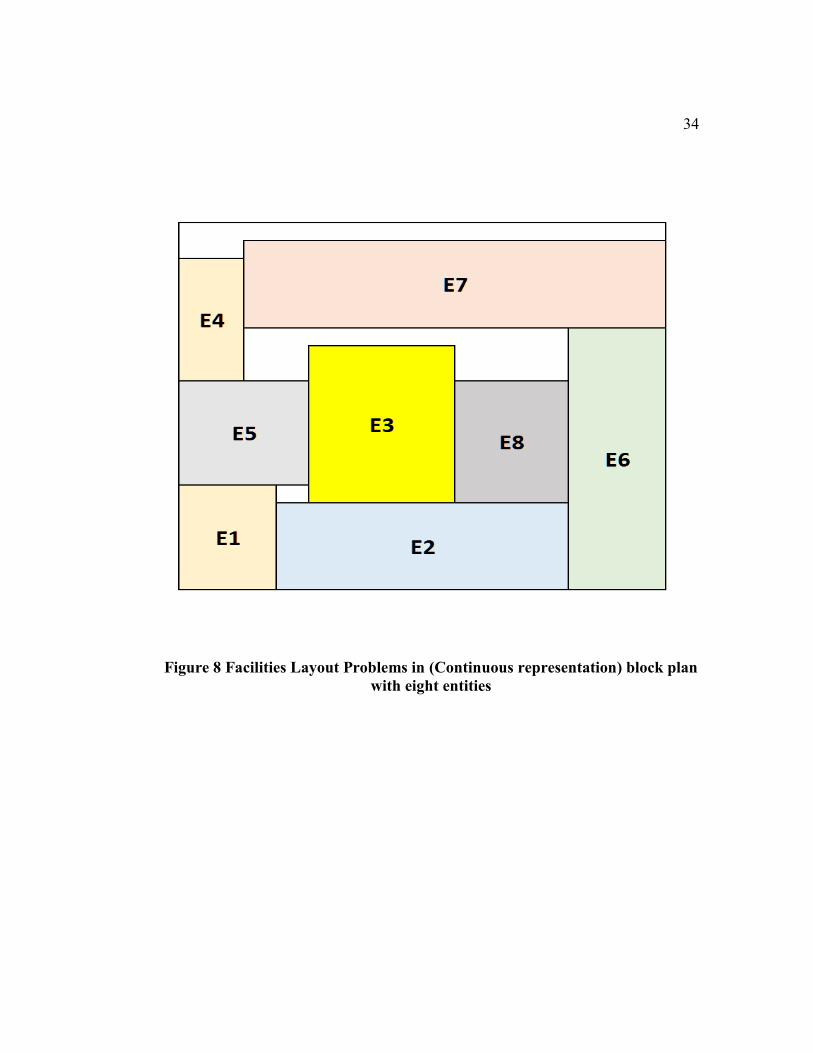
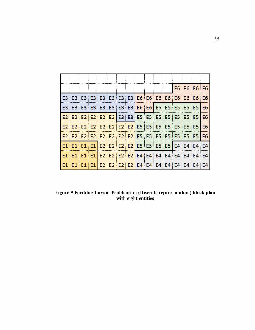
and finally operation. See Figure 8 and Figure 9.
34
Figure 8 Facilities Layout Problems in (Continuous representation) block plan
with eight entities
35
Figure 9 Facilities Layout Problems in (Discrete representation) block plan
with eight entities
36
The layout design reflects the strategies of the manufacturing facility.
Capacity requirements, material flows, and relationship activities are essential
elements forming the layout requirements. After that the affinity specifications are
determined. Configuration network diagrams are next stage in the planning process.
Finally, the layout sketch alternatives are developed and then weighted factor
analysis and evaluation process is conducted. (Kjell B. Zandin, 2001). Definitions
of facilities layout problem can be incorporated to : optimization problems with
objective to arrange relative locations of industrial facilities in more efficient non-
overlapping planar of unequal, rectangular areas inside total available space, taking
account for interactions with material handling systems, and aiming to (Drira et al.,
2007, p. 256):
minimize materials transportation costs,
minimize distance-based metrics, and
minimize the total material handling, and slack area costs
37
Facilities layout deals with micro-elements while its location deals with
macro-elements. (Tompkins, 2010, p. 7). Aisle structures and drop-off / pick-up
points are features that added to the block layout to produce a detailed layout.
(Singh & Sharma, 2006, p. 425). Layout planning is strategic decision where
expansion should be taken into account when planning and projects. Typical
design period for facilities spans 5-10 years with space requirement being the
dominant factors in the design specifications. (Tompkins, 2010, p. 119). The
planning process for facility layout produces a facility master plan document which
contains, plot plan, layout plan, vision, mission, goals and philosophy. The process
is iterative during the lifecycle development of the facility (Tompkins, 2010,
p. 808). Minimizing the transportation costs for all type of flows in Industrial
facilities such as air, water, air, waste, gas, information, and personnel, becomes of
crucial importance during the lifecycles of construction (capital expenditures) and
during operation (operational expenditures). The main outcome of facility layout
design is scaled plan of the physical entities in spatial dimensions and coordinates.
Optimization of the FLP is based on several objectives with respect to relative
entities positions. Materials flow and handling constitute around 70% of the
operational cost (Foulds & Hamacher, 2001, pp. 975–976). Costs saving due to
efficient facilities planning can reach up to 30 percent annually. (Singh & Sharma,
2006, p. 425). Moatari, et al, introduced a methodology for facilities layout
integration model. The proposed model take into consideration the occupational
health and safety for facilities layout planning by incorporating tools for risk
estimation. (Moatari-Kazerouni, Chinniah, & Agard, 2014). In their articles, Jain,
et al, presented latest survey on general facility planning and layout with future
provision of 3D formulation of facilities layout, capacitated facilities and
congestion, fuzzy formulations of input data, and multi-objective functions. (Jain,
38
Khare, & Mishra, 2013). Moslemipour, et al, elaborated on their paper about
flexible manufacturing system (FMS) specifically on dynamic and robust layouts,
and the use of intelligent approach as a resolution. (Moslemipour, Lee, & Rilling,
2012, p. 11).
In the industrial context, the layout problem is thought of as a hierarchy
model of subsystems. (Barsegar, p. 16). The subject of Facilities Layout Problem
is rich in the literature and hence several general and narrower reviews that has
been published in this field. In the literature of FLP, starting from more than
couple of decades ago, over dozen survey articles have been published, with the
most recent and non-topic-specific survey was on 2007; thereby requiring the need
for an up-to-date review. This thesis article (A Survey of Metaheuristics for
Facility Layout Problems) presents a through and survey and evaluation for
metaheuristics algorithms used for FLP. (Barsegar, p. 1). This thesis present
several categories of block layouts FLP heuristics like: QAP, GT, MIP...etc. Also,
the author present different FLP model extensions like stochastic, multi-criteria,
and dynamic layouts with special cases representations such as loop, cellular and
machine layouts.. (Barsegar, p. 17).

39
One of the recent surveys in the field of facilities layout which is specific on
loop based layout and material handling is by Asef-Vazair, (2005). Such article
emphasize the design sequence starting with (loop) material handling before facility
layout (cell location problem, CLP). (Asef-Vaziri & Laporte, 2005, p. 1). In their
survey paper, Keller & Buscher, presented the latest literature review with respect
to Single Row Layout Problem (SRLP). Single row reflect the main design feature
of the material handling system. This paper reviewed 82 papers published since
2000 in this subject. The majority of research have shown a deterministic input
type, static layout, and mixed-integer programming models, and predetermined
MHS. The article recommended to pursue research in cases of uncertainty in input
data, dynamic layout, operational requirement collection, asymmetric clearance,
quick and optimized exact solutions, and hybrid meta-heuristics. (Keller
& Buscher, 2015, p. 629). In this paper (Next Generation Factory Layout), authors
anticipated the directions for Next Generation Factory Layouts and how that will
show up in the new Layout planning based on uncertainty of production and
modularity in design. Such layouts emphasis on the responsiveness, scope and
reconfigurability. Trends in industry with respect to dynamics layout has been
highlighted. (Benjaafar et al., 2002). Among the FLP formulations and solutions
that were surveyed by Singh & Sharma are QAP, Graph Theory, and MIP. Also,
the authors surveyed solutions methodologies like exact procedure, heuristics,
metaheuristics and Artificial Intelligence. The articles shows the trends of FLP in
the last two decades where emphasis on metaheuristics solutions are becoming
apparent. (Singh & Sharma, 2006, p. 425). Tao, Wang et al., compared several
optimization approaches with emphasis on intelligent ones. Traditional FLP
formulations has been described in the article and optimization solutions
approaches has been explored with comparisons of several intelligent approaches.
40
Also, the authors discussed the future trends and showed new intelligent algorithms
such as Memetic Algorithm (MA), Artificial Bee Colony (ABC), and Artificial
Fish Swarm Algorithm (AFSA) are being adapted. (Tao, Wang, Qiao, & Tang,
2012, p. 502). In their articles, the authors introduced review on the
QAP applications in the real world; examples include hospital layout, electronic
boards wiring, archeology, and economics among others. The articles illustrated
the importance of QAP, discussed the solution complexity and then summarized
the current trends in QAP-related researches. (KumarBhati & Rasool, 2014, p. 42).
2.7.1. LP Planning Approach
Facilities planning strategies results from overall strategic plan and supply
chain management plans. (Tompkins, 2010, p. 293). In general, there are three
types of analytical types for facilities data management: Descriptive (diagnosis, or
modeling existing and deducing rules), prescriptive (apply rules to existing and
new), and Predictive (prognosis). The third type is related to stochastic modeling
of uncertainty of data input, while most planning approaches use the first two types.
Layout Problem is a complex field and such complexity invites all types of data
analytics. Complexity of LP raises due to its interdependency with other facility
aspects and with also the variability of its requirements and specifications. For
instance, two types of generating alternative layouts are: improvement type and
construction type. The first type is to modify or expand present layouts and the
second type is to develop layout from scratch. (Tompkins, 2010, p. 296). Physical
flow and relationship and process workflows comes before layout planning. Site-
specific conditions and operation-specific activities are important factors in layout
design process.
41
Among classical procedures for developing plant layouts are Apple's,
Reed's and Muther's as cited by Tompkins. The most widely adopted procedure is
Systematic Layout Planning (SLP) by Muther. The main ingredient in the SLP is
the activity relationship chart (ARC). The SLP procedure is divided into three
main stages: Analysis, Search, and Selection. In the analysis stage, based on input
data, two charts are used to develop the relationship diagram: the From-To chart for
the flow of materials and activity relationship chart for the activities. Then, space
requirements and availability are incorporated into the relationship diagram. Next,
at the search stage, constraints (physical and practical limitations) are incorporated
into the diagram resulting in space relationship diagram. Such diagram is used to
generate alternative block layout. The final stage is to evaluate each alternative
layout design and recommendations are made. (Tompkins, 2010, pp. 296–302)
2.7.2. LP Modeling & Formulation
Quantitative approach is appropriate for accurate evaluations of alternative
layout due to its objective criteria and accurate figures. Layout models are formal
scheme to generate layout with objective criteria for evaluation process.
(Tompkins, 2010, p. 302). Most of the layout problems are NP-hard (Drira et al.,
2007, p. 255). In a factory layout, a department represents the smallest indivisible
entity (Tompkins, 2010, p. 306). Space in the layout can take different
representations including: discrete units, areas and area & shape; which are
formulated respectively as one-to-one assignments, many-to-one assignments, and
blocking plan layout (Liggett, 2000, p. 198).
42
Typical problem formulation models are: QAP, Set cover, IP, MIP and
graph theories. (Barsegar, pp. 16–17). FLP optimization can be modeled in any
type of these three formalizations: SLP, simulations, and algorithmic mathematical
model. (Tao et al., 2012, p. 502). One of main models of FLP is QAP (Quadratic
Assignment Problem) model where the distance is computed by either Euclidean
norm or Manhattan norm. Graph theory (GT) is another major FL model in which
sum of activity relationship chart scores of pairs of adjacent facilities is maximized.
Such model can accommodate irregular-shape facilities. Most basic formulation of
FLP is on single objective namely minimizing the cost of total transportation or
flow, there are also the cases for multiple criteria (Foulds & Hamacher, 2001,
pp. 976–977). It is common to consider the distance among facilities to be
rectilinear distance (also known as Manhattan or taxicab distance) which is series
of orthogonal and straight lines constituting the path. Other common distance
model is the Euclidean distance which is a geometric straight-line distance.
(Tompkins, 2010, pp. 519–520). The taxicab metric is also known as rectilinear
distance, snake distance, city block distance, Manhattan distance or Manhattan
length. In Taxicab geometry, the distance between two points is the sum of the
absolute differences of their Cartesian coordinates. QAP formulation utilizes the
discrete representation while MIP utilizes the continuous one. (Barsegar, pp. 2–3).
QAP is a distance-based objective; hence when considering only the constraints
related to distance objectives, then FLP will be similar to QAP (Tompkins, 2010,
p. 304) see Table I and Table II. QAP is a type of combinatorial optimization
which depends on discrete decision variables. KumarBhati and Rasool (2014,
p. 43). QAP can be reformulated as MIP with extra constraints. (Singh & Sharma,
2006, p. 426). MILP has been used as an extension to the QAP to represent
continuous layout. (Singh & Sharma, 2006, p. 426).
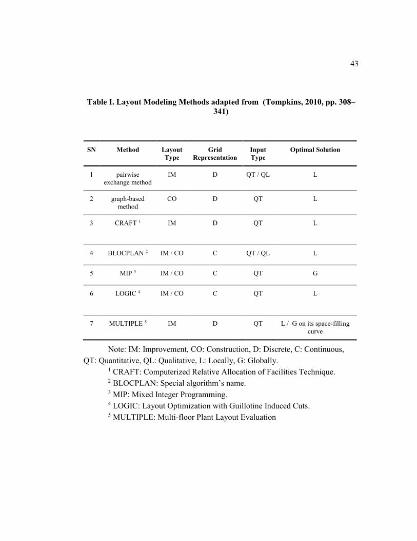
43
Table I. Layout Modeling Methods adapted from (Tompkins, 2010, pp. 308–
341)
SN Method Layout
Type
Grid
Representation
Input
Type
Optimal Solution
1 pairwise
exchange method
IM D QT / QL L
2 graph-based
method
CO D QT L
3 CRAFT 1 IM D QT L
4 BLOCPLAN 2 IM / CO C QT / QL L
5 MIP 3 IM / CO C QT G
6 LOGIC 4 IM / CO C QT L
7 MULTIPLE 5 IM D QT L / G on its space-filling
curve
Note: IM: Improvement, CO: Construction, D: Discrete, C: Continuous,
QT: Quantitative, QL: Qualitative, L: Locally, G: Globally. 1 CRAFT: Computerized Relative Allocation of Facilities Technique. 2 BLOCPLAN: Special algorithm’s name. 3 MIP: Mixed Integer Programming. 4 LOGIC: Layout Optimization with Guillotine Induced Cuts. 5 MULTIPLE: Multi-floor Plant Layout Evaluation
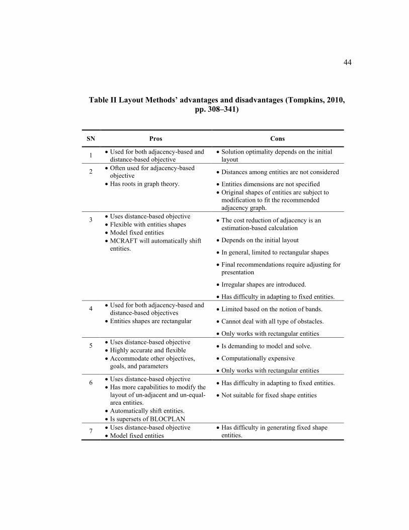
44
Table II Layout Methods’ advantages and disadvantages (Tompkins, 2010,
pp. 308–341)
SN Pros Cons
1 Used for both adjacency-based and
distance-based objective
Solution optimality depends on the initial
layout
2 Often used for adjacency-based
objective
Has roots in graph theory.
Distances among entities are not considered
Entities dimensions are not specified
Original shapes of entities are subject to
modification to fit the recommended
adjacency graph.
3 Uses distance-based objective
Flexible with entities shapes
Model fixed entities
MCRAFT will automatically shift
entities.
The cost reduction of adjacency is an
estimation-based calculation
Depends on the initial layout
In general, limited to rectangular shapes
Final recommendations require adjusting for
presentation
Irregular shapes are introduced.
Has difficulty in adapting to fixed entities.
4 Used for both adjacency-based and
distance-based objectives
Entities shapes are rectangular
Limited based on the notion of bands.
Cannot deal with all type of obstacles.
Only works with rectangular entities
5 Uses distance-based objective
Highly accurate and flexible
Accommodate other objectives,
goals, and parameters
Is demanding to model and solve.
Computationally expensive
Only works with rectangular entities
6 Uses distance-based objective
Has more capabilities to modify the
layout of un-adjacent and un-equal-
area entities.
Automatically shift entities.
Is supersets of BLOCPLAN
Has difficulty in adapting to fixed entities.
Not suitable for fixed shape entities
7 Uses distance-based objective
Model fixed entities
Has difficulty in generating fixed shape
entities.
45
In Graph theory, slicing trees (a.k.a. sliceable floorplans or cut-tree method)
are used to represent the layout relationship in a tree-graph format, where the end
nodes represent the facilities while internal nodes represent the division line
orientation (vertical vs. horizontal). Slicing tree is a typical formulation that suits
well for genetic algorithms. (Drira et al., 2007, p. 262). Graph-based methods
depend heavily on a mathematical graph's attribute called planarity. Resulted
layout alternative graphs are a subset of the relationship diagram which is a non-
planar graph. (Tompkins, 2010, p. 312). The notion of the maximal planar graph is
used to develop the adjacency graph. (Tompkins, 2010, p. 312). There are large
numbers of research articles about static layout problem. (Drira et al., 2007,
p. 259). For dynamic layouts, rearrangement costs of layouts are considered for
each planning period alongside the static layout objective costs such as material
handling. (Benjaafar et al., 2002). Dynamic layouts can be classified into two main
classes: 1) robust and distributed layouts for the high cost of re-layout, and 2)
dynamic and reconfigurable layouts for high uncertainty. (Benjaafar et al., 2002).
Typical Manufacturing layout types are:
1. Process layout ( job shops/ functional layouts / batch process)
2. Product layout (flow shops / assembly line / continuous process)
3. Production line layout Cellular (group / mixed / hybrid)
4. Fixed location layout (Project layout)
(Tompkins, 2010, p. 110)
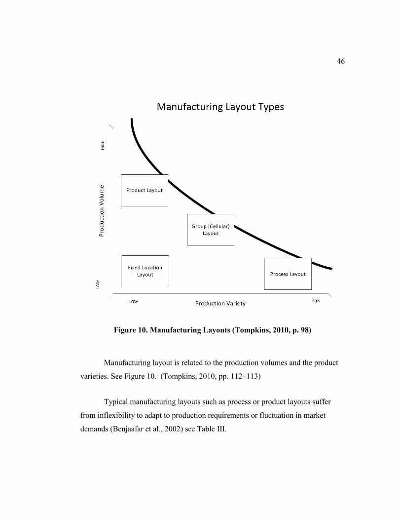
46
Figure 10. Manufacturing Layouts (Tompkins, 2010, p. 98)
Manufacturing layout is related to the production volumes and the product
varieties. See Figure 10. (Tompkins, 2010, pp. 112–113)
Typical manufacturing layouts such as process or product layouts suffer
from inflexibility to adapt to production requirements or fluctuation in market
demands (Benjaafar et al., 2002) see Table III.
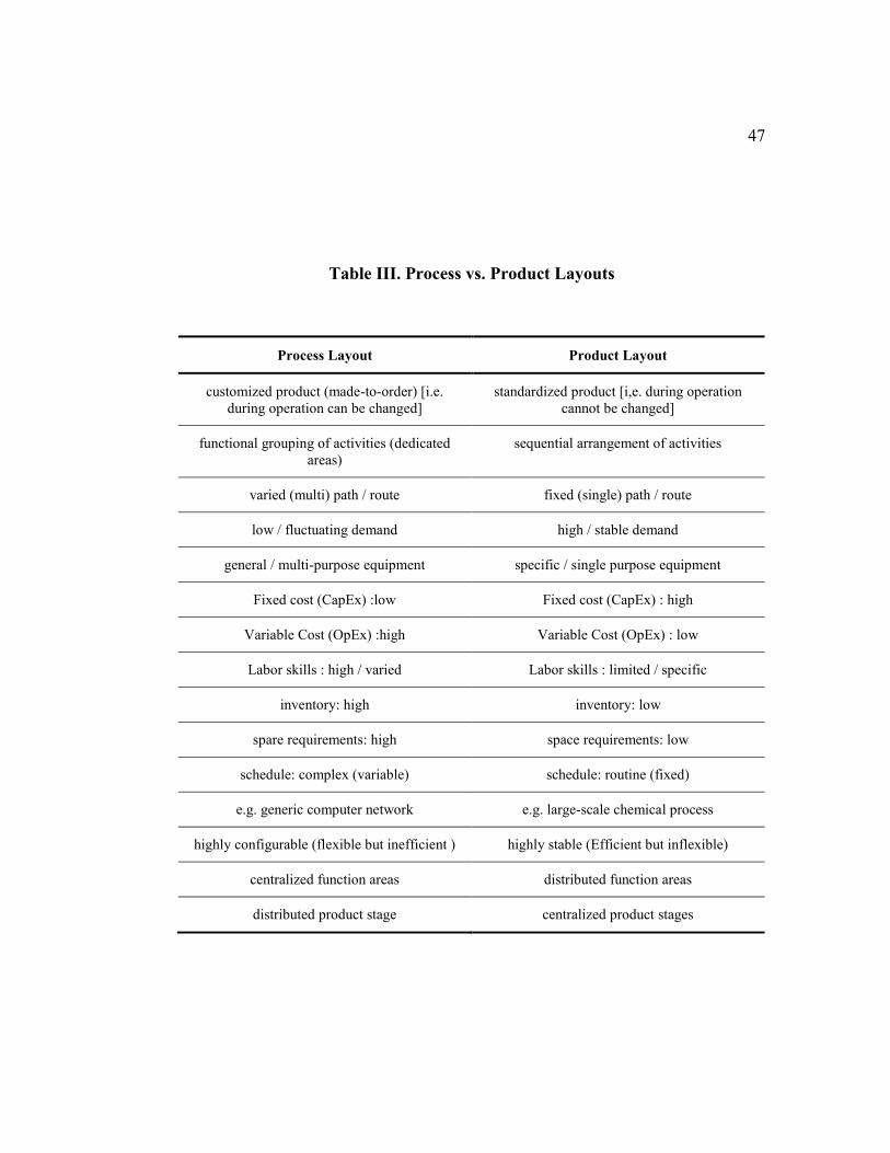
47
Table III. Process vs. Product Layouts
Process Layout Product Layout
customized product (made-to-order) [i.e.
during operation can be changed]
standardized product [i,e. during operation
cannot be changed]
functional grouping of activities (dedicated
areas)
sequential arrangement of activities
varied (multi) path / route fixed (single) path / route
low / fluctuating demand high / stable demand
general / multi-purpose equipment specific / single purpose equipment
Fixed cost (CapEx) :low Fixed cost (CapEx) : high
Variable Cost (OpEx) :high Variable Cost (OpEx) : low
Labor skills : high / varied Labor skills : limited / specific
inventory: high inventory: low
spare requirements: high space requirements: low
schedule: complex (variable) schedule: routine (fixed)
e.g. generic computer network e.g. large-scale chemical process
highly configurable (flexible but inefficient ) highly stable (Efficient but inflexible)
centralized function areas distributed function areas
distributed product stage centralized product stages
48
2.7.3. LP Constraints & Solution Methodologies
Space allocation solutions can be categorized into three broad approaches:
single criterion optimization (such as QAP), graph theory and multi-criteria
optimization (Liggett, 2000, p. 199). QAP was first presented as a facility location
formulation in 1950s by Beckmann and Koopmans (KumarBhati & Rasool, 2014,
p. 43). QAP model constraints presume block plan to be regular in shape that fits a
network of unit squares and giving no location is occupied by two facilities at the
same instance. (Foulds & Hamacher, 2001, p. 976). Also, space-filling curves are a
way to transfer a two-dimensional space into a linear vector. The layout problem is
then transformed into a problem similar to Linear Assignment Problem (LAP).
(Tompkins, 2010, p. 338). In realistic situations with facilities or activities of 15 or
more, QAP becomes infeasible due to a vast number of combinations (Liggett,
2000, p. 201). Examples of exact solutions of QAP are Branch & Bound, Dynamic
Programming, Cutting Plane, and Branch & Cut, (KumarBhati & Rasool, 2014,
p. 42). Solution methodologies can be categorized into the constructive placement
and the iterative improvements. The second type is dominated by large-scale
problems where Simulated Annealing and Genetic Algorithm are used (Liggett,
2000, pp. 201–202). Exact procedure can solve problem up to size of 16 in an
acceptable time. (Singh & Sharma, 2006, p. 426). Exact solutions are
computationally prohibitive with up to 40 entities can be solved optimally for
single row FLP cases. (Keller & Buscher, 2015, p. 639). Hybrid meta-heuristic
solutions are used to gain the advantages of the individual parents and to avoid
their drawbacks. (Keller & Buscher, 2015, p. 642)
49
In general, solving optimization problem in a single pass is preferred over
multi-pass solving techniques. (Tompkins, 2010, p. 353). Two solution
methodologies are generally used to solve combinatorial optimization as FLP. The
first method is called exact methods like: 'branch and bound', cutting-plane and
dynamic programming which lead to global optimal solutions. The second
approach is an approximate methods like heuristics and metaheuristics that lead to
local optimal solutions. (Drira et al., 2007, p. 262). For the approximate solution,
we have heuristics, metaheuristics, and artificial intelligence. Heuristics approach
are solutions to specific problems while metaheuristics are used as a framework for
general optimization problems. (KumarBhati & Rasool, 2014, p. 42). Examples of
heuristics are Constructions-based, improvement-based solutions. Examples of
metaheuristics include Genetic Algorithm (GA), Simulated Annealing (SA),
Evolutionary Algorithm (EA), Tabu Search (TS), and Scatter Search (SS). For
Artificial Intelligence, we have examples of Particle Swarm Optimization (PSO),
Ant Colony Optimization (ACO), Evolutionary Structural Optimization (ESO),
Expert Systems (ES), and Neural Networks (NN).
For real-life applications, there is a wide range of constraints like space
constraints, resource constraints, physical limitations, production constraints, safety
constraints, operation, constraints, etc. In addition, department or space shapes are
considered among the hard constraints like regular and irregular shapes, fixed-ratio
shapes, fixed-area shapes, loading and unloading positions, etc. Space constraints
include floor-loading limits, ceiling clearance, heat emission, etc (Tompkins, 2010,
p. 351). Fixed entities are physical obstacles with zero flow. (Tompkins, 2010,
p. 351).
50
In MIP, if entities dimensions are treated as known parameters, rectangular
shape and fixed, the problems will resemble that of packing algorithm; otherwise,
in cases of non-fix or ratio-based shapes, dimensions will be considered to be parts
of the decision variables with non-overlapping constraints applied. (Tompkins,
2010, p. 327). For practical implementation of MIP and for layout with a large
number of entities one might be inclined toward using heuristic solutions to get
satisfactory solutions that are not necessary optimal nonetheless. (Tompkins, 2010,
p. 330). Relaxing constraints of linear programming helps avoid nonlinearity and
increases the chances of having feasible solutions. (Tompkins, 2010, p. 331).
2.7.4. LP Algorithms
Algorithms provide a formal procedure to develop layout with objective
criteria for evaluation and optimization. (Tompkins, 2010, p. 302). Algorithms are
procedural implementations of the models of the problem, mostly done in computer
implementations for practicality. Such algorithms are necessary to evaluate largely
generated layout alternatives rapidly and help in most of "what-if" analysis.
(Tompkins, 2010, p. 303). Generally, algorithms may be categorized based on
input data type (qualitative, quantitative), objective functions (minimizing flows,
maximizing adjacency), or primary functions (construction, improvement).
(Tompkins, 2010, pp. 303–307).
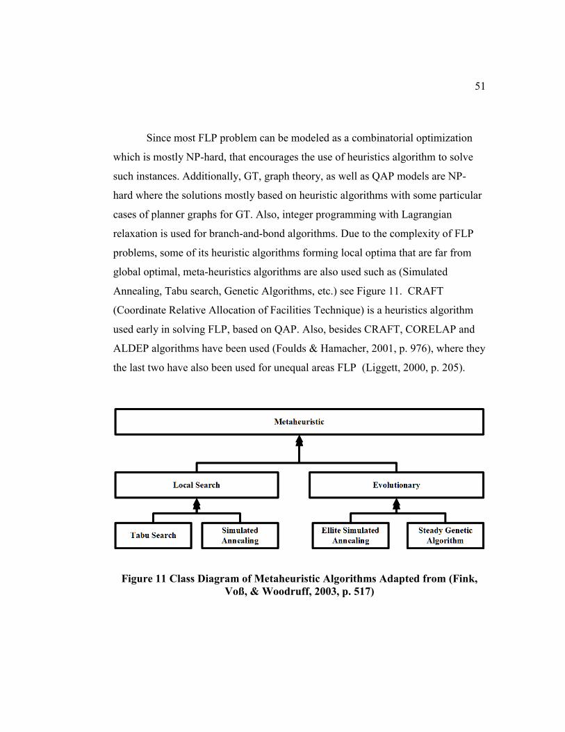
51
Since most FLP problem can be modeled as a combinatorial optimization
which is mostly NP-hard, that encourages the use of heuristics algorithm to solve
such instances. Additionally, GT, graph theory, as well as QAP models are NP-
hard where the solutions mostly based on heuristic algorithms with some particular
cases of planner graphs for GT. Also, integer programming with Lagrangian
relaxation is used for branch-and-bond algorithms. Due to the complexity of FLP
problems, some of its heuristic algorithms forming local optima that are far from
global optimal, meta-heuristics algorithms are also used such as (Simulated
Annealing, Tabu search, Genetic Algorithms, etc.) see Figure 11. CRAFT
(Coordinate Relative Allocation of Facilities Technique) is a heuristics algorithm
used early in solving FLP, based on QAP. Also, besides CRAFT, CORELAP and
ALDEP algorithms have been used (Foulds & Hamacher, 2001, p. 976), where they
the last two have also been used for unequal areas FLP (Liggett, 2000, p. 205).
Figure 11 Class Diagram of Metaheuristic Algorithms Adapted from (Fink,
Voß, & Woodruff, 2003, p. 517)
52
Simulated Annealing algorithm works with non-improving solutions in a
random selection to improve the local optimality and help to avoid locking local
regions of the space solution. (Tompkins, 2010, p. 345). The application of
Genetic Algorithms to FLP are increasing recently with various modifications to
the algorithm parameters. (Tompkins, 2010, p. 350). In general, SA outperforms
GA for single solution evaluation (Tompkins, 2010, p. 351). Other examples of
layout algorithms as cited by Tompkins include ALDEP, COFAD, CORELAP,
PLANET, DISCON, FLAC, and SHARE. (Tompkins, 2010, p. 365). Among
metaheuristics algorithms are Tabu search, Simulated Annealing, Genetic
Algorithms, and Ant Colony Algorithms. (Drira et al., 2007, p. 262). Artificial
Intelligence algorithms are inspired by naturally occurred behaviors in a swarm of
biological beings such as ants, bees, and others. (Barsegar, p. 9).
For a detailed study of metaheuristics and corresponding algorithms, we
refer the reader to (Luke, 2013), (Gendreau & Potvin, 2010), (Skiena, 2008), (Fink,
Voß, & Woodruff, 2003), (Voß, 2001), and (Barsegar)
53
2.7.5. LP Evaluation, Performance Measurements & Metrics
Dr. James Harrington once summarized the importance of measurement in
the ability to control the performance and hence promote improvements and
optimization. System requirements form the basis on which the quantifiable
measurement is developed (Arrasmith, 2015, p. 399). Most of the performance
measurements can be categorized based on systems design considerations which
form the highest level of design objectives hierarchy as seen in Figure 12
(Blanchard & Fabrycky, 2011, p. 41). In System Engineering, performance metrics
extend across system lifecycle stages.
MOE: stated from the stakeholder perspective, is the indicator of
success to meet the mission objectives. MOE corresponds to the
stakeholder requirements and specification and is used mostly during
system validation
MOP: used to quantify the requirement. MOPs corresponds to the
system specifications and architecture design. MOPs are derived from
MOEs and used mostly during system verification.
TPM: a quantitative value for attributes innate in the system design
(Blanchard & Fabrycky, 2011, p. 40). TPM measures characteristics of
a system design attribute that satisfy the technical requirement. TPM
corresponds to the system details specifications and design. TPMs are
derived from MOPs.
There is a difference between metrics and measurements. Metrics are like
goals that are used for targeting performance, as a success evaluation objectives, or
as comparison criteria. Whereas, measures are quantitative scales of characteristics
of targeted like direct measurements.
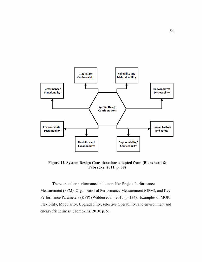
54
Figure 12. System Design Considerations adapted from (Blanchard &
Fabrycky, 2011, p. 38)
There are other performance indicators like Project Performance
Measurement (PPM), Organizational Performance Measurement (OPM), and Key
Performance Parameters (KPP) (Walden et al., 2015, p. 134). Examples of MOP:
Flexibility, Modularity, Upgradability, selective Operability, and environment and
energy friendliness. (Tompkins, 2010, p. 5).
55
Lin & Sharp have proposed another framework to evaluate the plant layout.
The framework is a structure of 18 criteria organized into three levels, criteria
groups, criteria classes and criteria. Each criteria is expressed with specific weight
and appropriate rating measurement, then its rating is normalized, then integrated to
indicate the overall index with respect to other alternatives. In addition, the paper
has suggested six types of integration methodologies and argued that they are
superiors to normal AHP methodology. Space utilization, Clearance, aisle,
production cost, land cost, building expansion, human safety, and access for
maintenance are among criteria studied by the article. (Lin & Sharp, 1999, p. 118).
Here are some examples of measures in the cases of Facilities Layout; an example
of Performance indicator is the space utilization efficiency which mostly measured
by how much usage of the total required space vs. the total available space. Also,
an example of Recyclability is the usability of leftover space, which is the
remaining space after layout design of the total available space of the facility. In
addition, such leftover space is a major factor in “Flexibility and Expandability”.
For human factors and safety, an example would be about the distance between
human occupants and certain defined danger zones. Moreover, the facility layout
design would impact the trend and behavior of human occupants traveling in
conducting business requirements. Also, human accessibility into the human-
operated machines would influence the layout by balancing multiple objectives
including performance efficiency vs. human factors and maintainability.
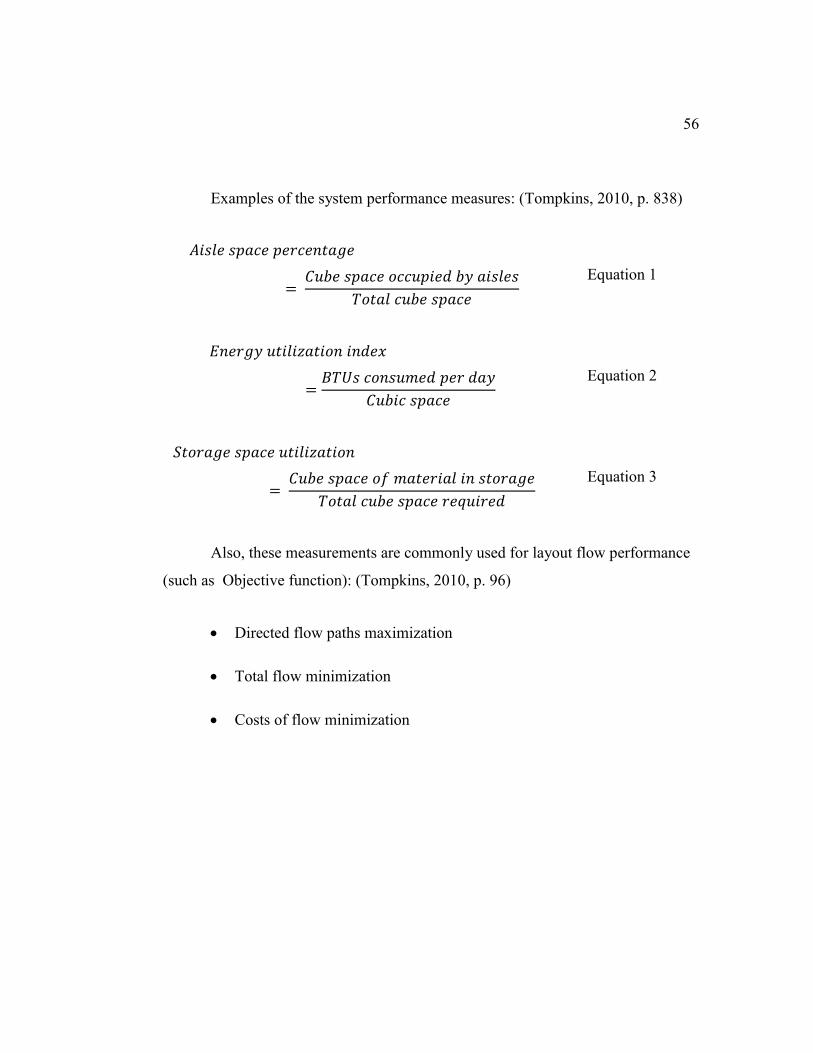
56
Examples of the system performance measures: (Tompkins, 2010, p. 838)
𝐴𝑖𝑠𝑙𝑒 𝑠𝑝𝑎𝑐𝑒 𝑝𝑒𝑟𝑐𝑒𝑛𝑡𝑎𝑔𝑒
= 𝐶𝑢𝑏𝑒 𝑠𝑝𝑎𝑐𝑒 𝑜𝑐𝑐𝑢𝑝𝑖𝑒𝑑 𝑏𝑦 𝑎𝑖𝑠𝑙𝑒𝑠
𝑇𝑜𝑡𝑎𝑙 𝑐𝑢𝑏𝑒 𝑠𝑝𝑎𝑐𝑒
Equation 1
𝐸𝑛𝑒𝑟𝑔𝑦 𝑢𝑡𝑖𝑙𝑖𝑧𝑎𝑡𝑖𝑜𝑛 𝑖𝑛𝑑𝑒𝑥
=𝐵𝑇𝑈𝑠 𝑐𝑜𝑛𝑠𝑢𝑚𝑒𝑑 𝑝𝑒𝑟 𝑑𝑎𝑦
𝐶𝑢𝑏𝑖𝑐 𝑠𝑝𝑎𝑐𝑒
Equation 2
𝑆𝑡𝑜𝑟𝑎𝑔𝑒 𝑠𝑝𝑎𝑐𝑒 𝑢𝑡𝑖𝑙𝑖𝑧𝑎𝑡𝑖𝑜𝑛
= 𝐶𝑢𝑏𝑒 𝑠𝑝𝑎𝑐𝑒 𝑜𝑓 𝑚𝑎𝑡𝑒𝑟𝑖𝑎𝑙 𝑖𝑛 𝑠𝑡𝑜𝑟𝑎𝑔𝑒
𝑇𝑜𝑡𝑎𝑙 𝑐𝑢𝑏𝑒 𝑠𝑝𝑎𝑐𝑒 𝑟𝑒𝑞𝑢𝑖𝑟𝑒𝑑
Equation 3
Also, these measurements are commonly used for layout flow performance
(such as Objective function): (Tompkins, 2010, p. 96)
Directed flow paths maximization
Total flow minimization
Costs of flow minimization
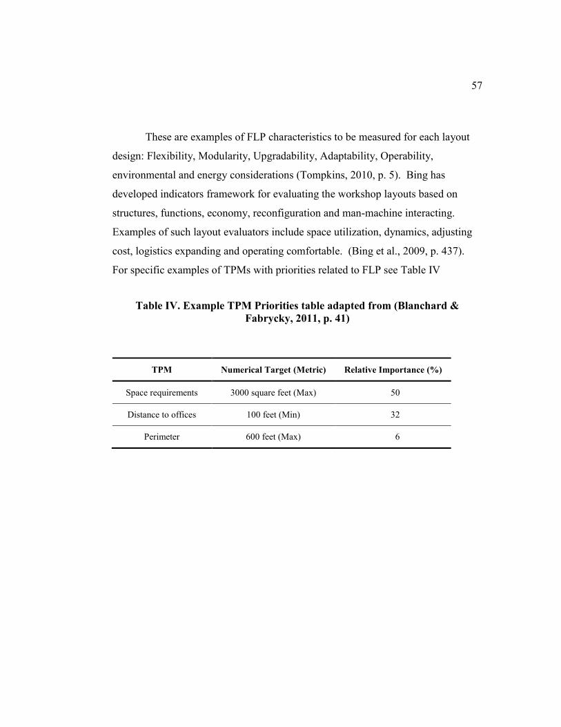
57
These are examples of FLP characteristics to be measured for each layout
design: Flexibility, Modularity, Upgradability, Adaptability, Operability,
environmental and energy considerations (Tompkins, 2010, p. 5). Bing has
developed indicators framework for evaluating the workshop layouts based on
structures, functions, economy, reconfiguration and man-machine interacting.
Examples of such layout evaluators include space utilization, dynamics, adjusting
cost, logistics expanding and operating comfortable. (Bing et al., 2009, p. 437).
For specific examples of TPMs with priorities related to FLP see Table IV
Table IV. Example TPM Priorities table adapted from (Blanchard &
Fabrycky, 2011, p. 41)
TPM Numerical Target (Metric) Relative Importance (%)
Space requirements 3000 square feet (Max) 50
Distance to offices 100 feet (Min) 32
Perimeter 600 feet (Max) 6
58
Tompkins suggested three shape measurement and shape control for layout
evaluation. Some of such measurement are to avoid irregularity in generated
shapes, while other only for detection. The first measurement is based on the value
of the shape area divided by smallest enclosing rectangle (SER). The second
measurement is the ratio of the length of SER over its width. The third
measurement is for detection only which generate an index value that indicates the
irregularity of shapes. Such measurement is obtained by dividing the ratio of SER
perimeter to its area. Such measurement helps with detection of cases with voids
inside generated shapes. (Tompkins, 2010, pp. 342–344).
Frequently used optimization objectives are: minimizing flows volume,
traveling distance, cost or time. (Singh & Sharma, 2006, p. 426). Main objectives
of many types of research are to minimize traveling costs like travel time, travel
distance or material handling costs. (Drira et al., 2007, p. 261). Examples of
metrics and evaluation criteria: work-in-progress, lead times, manufacturing costs,
and productivity. (Barsegar, p. 15). Another example of metrics related directly to
the layout is adjacency score (based on from-to chart = quantitative input) and
efficiency rating (based on relationship chart = qualitative input). (Tompkins, 2010,
p. 324).
59
In their paper, Yang & Hung, investigated decision making in the process of
layout design problem. Normal and fuzzy Technique of order preference by
similarity to ideal solution (TOPSIS) have been used as multiple-attributed decision
making (MADM). Authors have investigated the multi-objectives criteria such as
accessibility, maintenance, and flexibility among others. MADM is close in notion
to the mathematical goal programming. The used methodologies help provide
systematic evaluation to alternative layouts which facilitate the decision making
process; more detailed information can be found in the paper. (Yang & Hung,
2007, p. 126). Performance measurement is an important requirement for decision
making process in which such measurement steers the design of optimization
problem. (Raman, Nagalingam, & Lin, 2009, p. 191). The paper by Raman treated
the problem with most of the layout models that aims for only the design stage
evaluation and hence limits the capability of making decision valid for the facilities
layouts' whole life cycles. The authors considered three significant factors that are
important to calculate the effective performance measurement; those factors were:
facilities layout flexibility, productive area utilization, and closeness gap. Case
study was developed to illustrate the case of performance measurement with
emphasis on closeness gap (Raman et al., 2009, p. 191).

60
2.8. Data Extraction and Results
This section will contain the comparison of different works on the topic,
represented in a tabular form. This table’s entries (i.e., columns) have been adapted
from (Drira, Pierreval, & Hajri-Gabouj, 2007), (Keller & Buscher, 2015), and
(Saravanan & Ganesh Kumar, 2013) tree representation of layout problems.
Metaheuristics classes and algorithms are generally not mutually exclusive and in
several cases are hybrid of different categories.
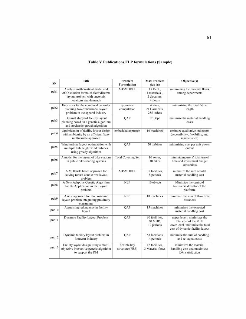
61
Table V Publications FLP formulations (Sample)
SN Title Problem
Formulation
Max Problem
size (n)
Objective(s)
pub1 A robust mathematical model and
ACO solution for multi-floor discrete
layout problem with uncertain locations and demands
ABSMODEL 17 Dept.,
4 materials. ,
2 elevators, 4 floors
minimizing the material flows
among departments
pub2 Heuristics for the combined cut order
planning two-dimensional layout
problem in the apparel industry
geometric
computation
4 sizes,
21 Garments,
255 orders
minimizing the total fabric
length
pub3 Optimal shipyard facility layout
planning based on a genetic algorithm
and stochastic growth algorithm
QAP 17 Dept. minimize the material handling
costs
pub4 Optimization of facility layout design
with ambiguity by an efficient fuzzy
multivariate approach
embedded approach 10 machines optimize qualitative indicators
(accessibility, flexibility, and
maintenance)
pub5 Wind turbine layout optimization with
multiple hub height wind turbines
using greedy algorithm
QAP 20 turbines minimizing cost per unit power
output
pub6 A model for the layout of bike stations
in public bike-sharing systems
Total Covering Set 10 zones,
30 bikes
minimizing users’ total travel
time and investment budget constraints
pub7 A MOEA/D based approach for
solving robust double row layout
problem
ABSMODEL 35 facilities,
5 periods
minimize the sum of total
material handling cost
pub8 A New Adaptive Genetic Algorithm
and Its Application in the Layout
problem
NLP 16 objects Minimize the centroid
transverse deviator of the
platform.
pub9 A new approach for loop machine
layout problem integrating proximity
constraints
NLP 10 machines minimize the sum of flow time
distances
pub10 Appraising redundancy in facility
layout QAP 15 machines minimizes the expected
material handling cost
pub11 Dynamic Facility Layout Problem QAP 60 facilities,
30 MHD, 12 periods
upper level : minimizes the
total cost of the MHS lower level : minimize the total
cost of dynamic facility layout
pub12 Dynamic facility layout problem in
footwear industry
QAP 54 locations
4 periods
minimize the sum of handling
and re-layout costs
pub13 Facility layout design using a multi-
objective interactive genetic algorithm
to support the DM
flexible bay
structure (FBS)
12 facilities,
3 Material flows
minimizes the material
handling cost and maximizes
DM satisfaction
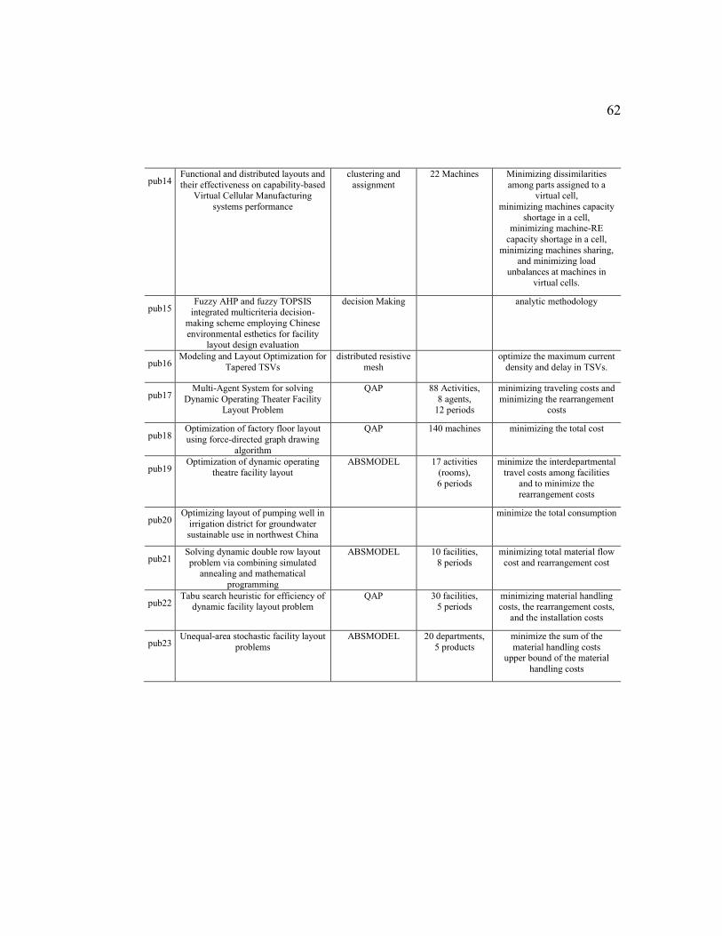
62
pub14 Functional and distributed layouts and
their effectiveness on capability-based Virtual Cellular Manufacturing
systems performance
clustering and
assignment
22 Machines Minimizing dissimilarities
among parts assigned to a virtual cell,
minimizing machines capacity
shortage in a cell, minimizing machine-RE
capacity shortage in a cell,
minimizing machines sharing, and minimizing load
unbalances at machines in
virtual cells.
pub15 Fuzzy AHP and fuzzy TOPSIS
integrated multicriteria decision-
making scheme employing Chinese
environmental esthetics for facility layout design evaluation
decision Making analytic methodology
pub16 Modeling and Layout Optimization for
Tapered TSVs
distributed resistive
mesh
optimize the maximum current
density and delay in TSVs.
pub17 Multi-Agent System for solving
Dynamic Operating Theater Facility Layout Problem
QAP 88 Activities,
8 agents, 12 periods
minimizing traveling costs and
minimizing the rearrangement costs
pub18 Optimization of factory floor layout
using force-directed graph drawing
algorithm
QAP 140 machines minimizing the total cost
pub19 Optimization of dynamic operating
theatre facility layout
ABSMODEL 17 activities
(rooms),
6 periods
minimize the interdepartmental
travel costs among facilities
and to minimize the
rearrangement costs
pub20 Optimizing layout of pumping well in
irrigation district for groundwater sustainable use in northwest China
minimize the total consumption
pub21 Solving dynamic double row layout
problem via combining simulated annealing and mathematical
programming
ABSMODEL 10 facilities,
8 periods
minimizing total material flow
cost and rearrangement cost
pub22 Tabu search heuristic for efficiency of
dynamic facility layout problem QAP 30 facilities,
5 periods minimizing material handling costs, the rearrangement costs,
and the installation costs
pub23 Unequal-area stochastic facility layout
problems
ABSMODEL 20 departments,
5 products
minimize the sum of the
material handling costs upper bound of the material
handling costs
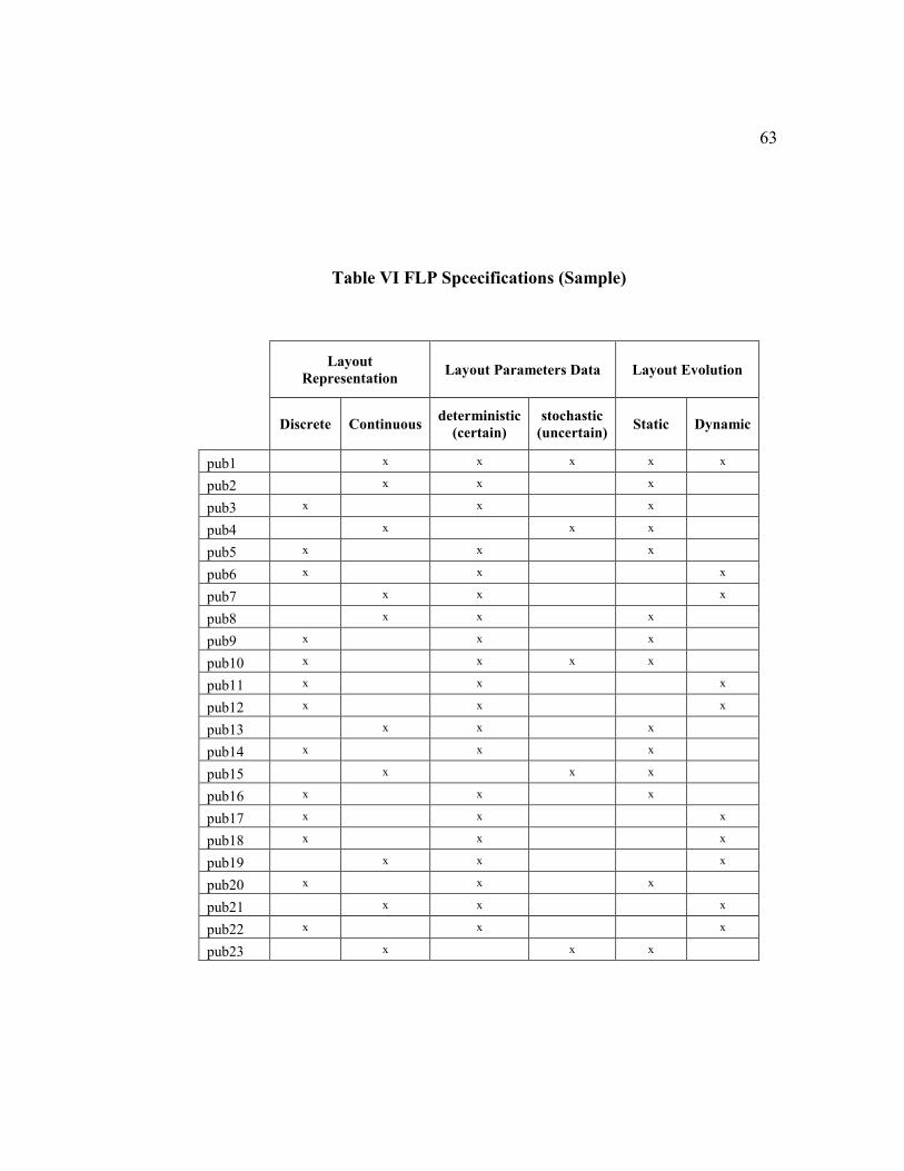
63
Table VI FLP Spcecifications (Sample)
Layout
Representation Layout Parameters Data Layout Evolution
Discrete Continuous deterministic
(certain)
stochastic
(uncertain) Static Dynamic
pub1 x x x x x
pub2 x x x
pub3 x x x
pub4 x x x
pub5 x x x
pub6 x x x
pub7 x x x
pub8 x x x
pub9 x x x
pub10 x x x x
pub11 x x x
pub12 x x x
pub13 x x x
pub14 x x x
pub15 x x x
pub16 x x x
pub17 x x x
pub18 x x x
pub19 x x x
pub20 x x x
pub21 x x x
pub22 x x x
pub23 x x x
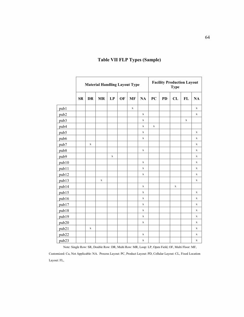
64
Table VII FLP Types (Sample)
Material Handling Layout Type Facility Production Layout
Type
SR DR MR LP OF MF NA PC PD CL FL NA
pub1 x x
pub2 x x
pub3 x x
pub4 x x
pub5 x x
pub6 x x
pub7 x x
pub8 x x
pub9 x x
pub10 x x
pub11 x x
pub12 x x
pub13 x x
pub14 x x
pub15 x x
pub16 x x
pub17 x x
pub18 x x
pub19 x x
pub20 x x
pub21 x x
pub22 x x
pub23 x x
Note: Single Row: SR, Double Row: DR, Multi Row: MR, Loop: LP, Open Field, OF, Multi Floor: MF,
Customized: Cu, Not Applicable: NA. Process Layout: PC, Product Layout: PD, Cellular Layout: CL, Fixed Location
Layout: FL,
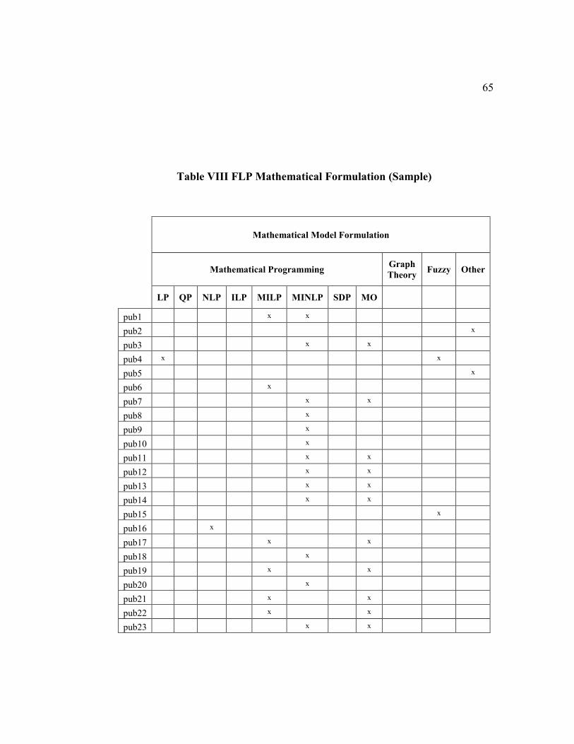
65
Table VIII FLP Mathematical Formulation (Sample)
Mathematical Model Formulation
Mathematical Programming Graph
Theory Fuzzy Other
LP QP NLP ILP MILP MINLP SDP MO
pub1 x x
pub2 x
pub3 x x
pub4 x x
pub5 x
pub6 x
pub7 x x
pub8 x
pub9 x
pub10 x
pub11 x x
pub12 x x
pub13 x x
pub14 x x
pub15 x
pub16 x
pub17 x x
pub18 x
pub19 x x
pub20 x
pub21 x x
pub22 x x
pub23 x x
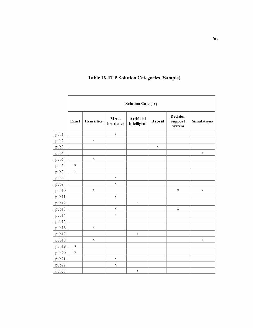
66
Table IX FLP Solution Categories (Sample)
Solution Category
Exact Heuristics Meta-
heuristics
Artificial
Intelligent Hybrid
Decision
support
system
Simulations
pub1 x
pub2 x
pub3 x
pub4 x
pub5 x
pub6 x
pub7 x
pub8 x
pub9 x
pub10 x x x
pub11 x
pub12 x
pub13 x x
pub14 x
pub15
pub16 x
pub17 x
pub18 x x
pub19 x
pub20 x
pub21 x
pub22 x
pub23 x
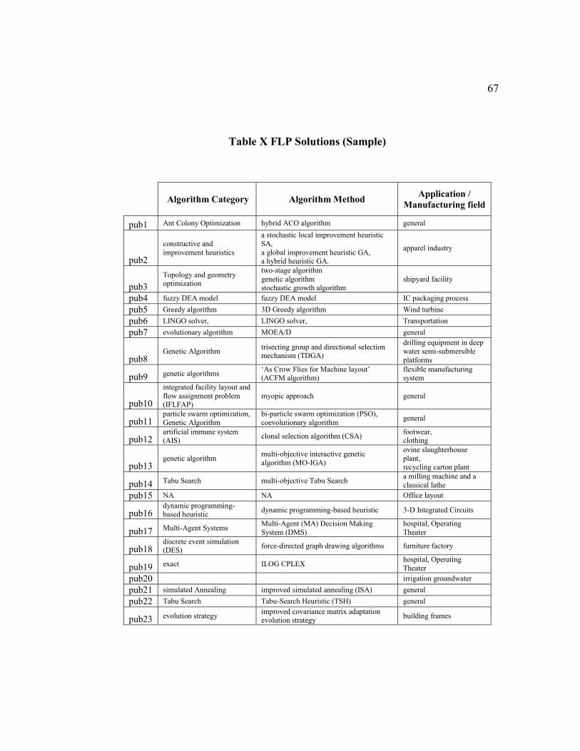
67
Table X FLP Solutions (Sample)
Algorithm Category Algorithm Method Application /
Manufacturing field
pub1 Ant Colony Optimization hybrid ACO algorithm general
pub2
constructive and
improvement heuristics
a stochastic local improvement heuristic
SA,
a global improvement heuristic GA, a hybrid heuristic GA.
apparel industry
pub3
Topology and geometry optimization
two-stage algorithm
genetic algorithm
stochastic growth algorithm
shipyard facility
pub4 fuzzy DEA model fuzzy DEA model IC packaging process
pub5 Greedy algorithm 3D Greedy algorithm Wind turbine
pub6 LINGO solver, LINGO solver, Transportation
pub7 evolutionary algorithm MOEA/D general
pub8 Genetic Algorithm
trisecting group and directional selection mechanism (TDGA)
drilling equipment in deep
water semi-submersible
platforms
pub9 genetic algorithms ‘As Crow Flies for Machine layout’ (ACFM algorithm)
flexible manufacturing system
pub10
integrated facility layout and
flow assignment problem (IFLFAP)
myopic approach general
pub11 particle swarm optimization,
Genetic Algorithm
bi-particle swarm optimization (PSO),
coevolutionary algorithm general
pub12 artificial immune system (AIS)
clonal selection algorithm (CSA) footwear, clothing
pub13 genetic algorithm
multi-objective interactive genetic
algorithm (MO-IGA)
ovine slaughterhouse
plant, recycling carton plant
pub14 Tabu Search multi-objective Tabu Search a milling machine and a
classical lathe
pub15 NA NA Office layout
pub16 dynamic programming-based heuristic
dynamic programming-based heuristic 3-D Integrated Circuits
pub17 Multi-Agent Systems Multi-Agent (MA) Decision Making
System (DMS)
hospital, Operating
Theater
pub18 discrete event simulation (DES)
force-directed graph drawing algorithms furniture factory
pub19 exact ILOG CPLEX hospital, Operating
Theater
pub20 irrigation groundwater
pub21 simulated Annealing improved simulated annealing (ISA) general
pub22 Tabu Search Tabu-Search Heuristic (TSH) general
pub23 evolution strategy improved covariance matrix adaptation evolution strategy
building frames
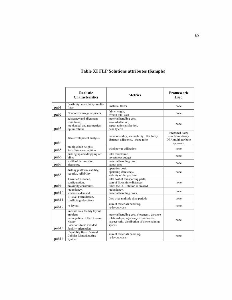
68
Table XI FLP Solutions attributes (Sample)
Realistic
Characteristics Metrics
Framework
Used
pub1 flexibility, uncertainty, multi-floor
material flows none
pub2 Nonconvex irregular pieces. fabric length,
overall total cost none
pub3
adjacency and alignment conditions,
topological and geometrical
optimizations
material handling cost, area satisfaction,
aspect ratio satisfaction,
penalty cost
none
pub4
data envelopment analysis maintainability, accessibility, flexibility,
distance, adjacency, shape ratio
integrated fuzzy simulation-fuzzy
DEA multi attribute
approach
pub5 multiple hub heights,
Safe distance condition wind power utilization none
pub6 picking up and dropping off
bikes
total travel time,
investment budget none
pub7 width of the corridor,
clearance,
material handling cost,
layout area none
pub8
drilling platform stability,
security, reliability
operation cost,
operating efficiency, stability of the platform
none
pub9
Travelled distance,
configuration, proximity constraints
total cost of transporting parts,
sum of flows time distances, times the LUL station is crossed
none
pub10 redundancy,
stochastic demand
redundancy,
material handling costs, none
pub11 Bi-level Formulation, conflicting objectives
flow over multiple time periods none
pub12 re-layout sum of materials handling,
re-layout costs none
pub13
unequal area facility layout problem
participation of the Decision
Maker Locations to be avoided
Facility orientation
material handling cost, closeness , distance
relationships, adjacency requirements
,aspect ratio, distribution of the remaining spaces
none
pub14
Capability Based Virtual Cellular Manufacturing
System
sum of materials handling,
re-layout costs none
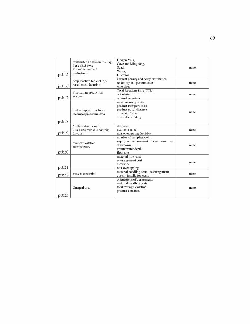
69
pub15
multicriteria decision-making
Feng Shui style
Fuzzy hierarchical evaluations
Dragon Vein,
Cave and Ming-tang, Sand,
Water,
Direction
none
pub16
deep reactive Ion etching-based manufacturing
Current density and delay distribution
reliability and performance.
wire sizes
none
pub17
Fluctuating production
system.
Total Relations Rate (TTR) orientation
optimal activities
none
pub18
multi-purpose machines technical procedure data
manufacturing costs, product transport costs
product travel distance
amount of labor costs of relocating
none
pub19
Multi-section layout,
Fixed and Variable Activity
Layout
distances
available areas,
non-overlapping facilities
none
pub20
over-exploitation
sustainability
number of pumping well
supply and requirement of water resources
drawdown, groundwater depth,
flow rate
none
pub21
material flow cost rearrangement cost
clearance
non-overlapping
none
pub22 budget constraint material handling costs, rearrangement costs, installation costs
none
pub23
Unequal-area
orientations of departments
material handling costs total average violation
product demands none
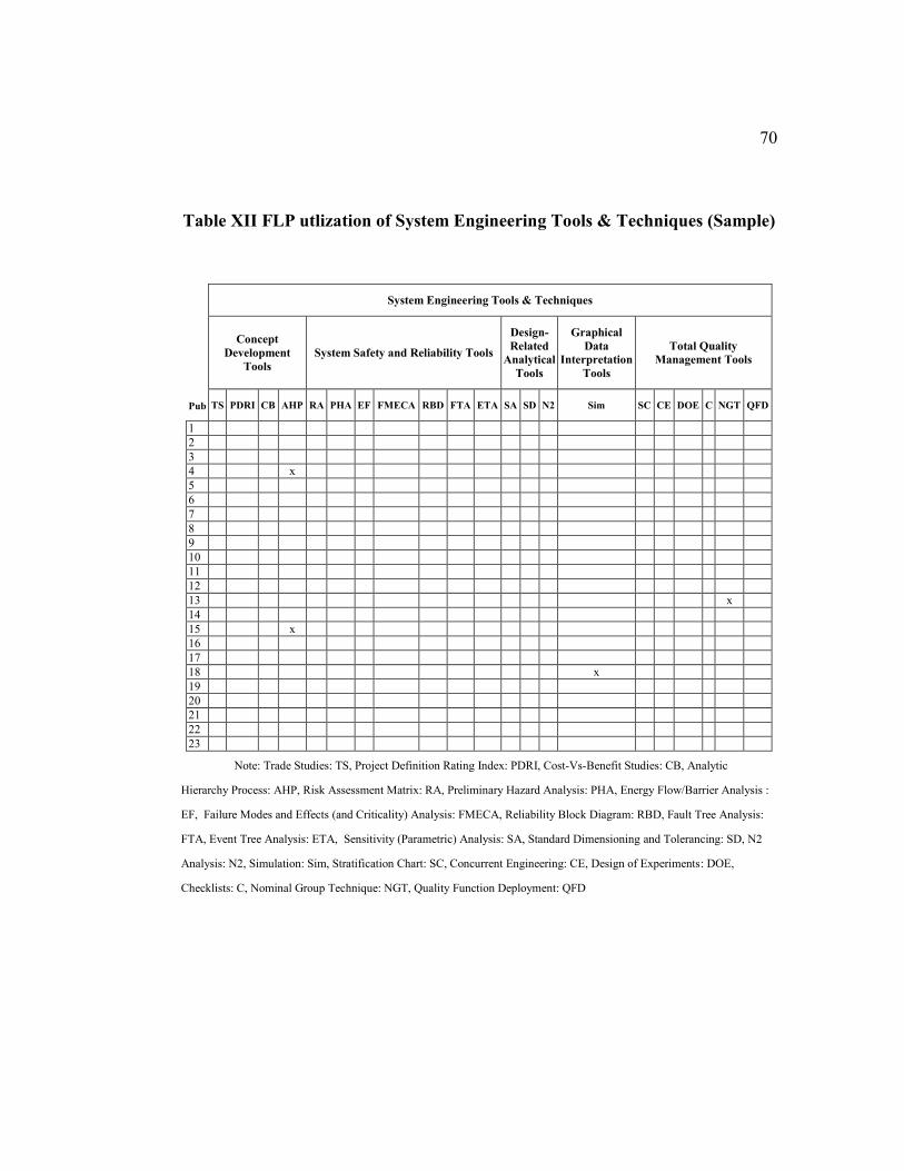
70
Table XII FLP utlization of System Engineering Tools & Techniques (Sample)
System Engineering Tools & Techniques
Concept
Development
Tools
System Safety and Reliability Tools
Design-
Related
Analytical
Tools
Graphical
Data
Interpretation
Tools
Total Quality
Management Tools
Pub TS PDRI CB AHP RA PHA EF FMECA RBD FTA ETA SA SD N2 Sim SC CE DOE C NGT QFD
1
2
3
4 x
5
6
7
8
9
10
11
12
13 x
14
15 x
16
17
18 x
19
20
21
22
23
Note: Trade Studies: TS, Project Definition Rating Index: PDRI, Cost-Vs-Benefit Studies: CB, Analytic
Hierarchy Process: AHP, Risk Assessment Matrix: RA, Preliminary Hazard Analysis: PHA, Energy Flow/Barrier Analysis :
EF, Failure Modes and Effects (and Criticality) Analysis: FMECA, Reliability Block Diagram: RBD, Fault Tree Analysis:
FTA, Event Tree Analysis: ETA, Sensitivity (Parametric) Analysis: SA, Standard Dimensioning and Tolerancing: SD, N2
Analysis: N2, Simulation: Sim, Stratification Chart: SC, Concurrent Engineering: CE, Design of Experiments: DOE,
Checklists: C, Nominal Group Technique: NGT, Quality Function Deployment: QFD
71
2.9. Implications, Limitation, Resolutions & Recommendations
This literature review reveals the current degree of System Engineering
involvements on the complex issue of facility layout design, which is the main
novelty of this study alongside the suggested use of System Engineering tools and
techniques in the appropriate stage. Utilizing the System Engineering tools such as
QFD or AHP will help in identifying and prioritizing TPMs, each TPM’s relative
degree of importance is to be indicated to facilitate the evaluation process
(Blanchard & Fabrycky, 2011, p. 82). Such levels of importance will reflect on the
weights of multi-objective mathematical programming.
We performed analysis of such historical research trends and we detected
that poor use of system engineering approach to facility layout can be attributed to:
Lack of precise definition of the facilities, departments, machines,
equipment, etc.
Lack of proper system requirements with different priorities for
facilities layout.
Incomplete representation of the real world requirements and
specifications.
Lack of plan for performance measurement management.
72
Several System Engineering tools and techniques can be recommended for
FLP, for example, N2 diagram is a straightforward diagram that shows the
interactions among related entities like which one is the other inputs or outputs.
Such diagram is very similar to well-known diagram that is widely used in FLP
which is the From-To relationship diagram. (Walden et al., 2015, pp. 198–199).
The capabilities and simplicities of the N2 diagram can be further exploited with
different versions for each type of flow movements or each type of interactions;
such usage will result in a multi-modal representation of all significant and
substantial flow patterns among the various entities of the layout.
2.10. Literature Review Conclusion
In conclusion, the purpose of this literature review survey was to anticipate
recent trends in FLP, to highlight the most proven models, solutions, and
algorithms, and to gather data on the use of System Engineering approach on FLP.
Over the last years, FLP research has shown the value of effective problem
formulations and solution techniques in the FLP field. From the data analysis, most
practical solutions of FLP are those pertaining to meta-heuristics techniques due to
its robust and rigorous results.
In this chapter we have: 1) Introduced the theoretical framework on which
the study is based; 2) Provide background on related subjects as material handling
systems and System Engineering framework; 3) Indicated the trends in FLP
research field.

73
Lastly, some of System Engineering tools and techniques has been used
with overall very positive results indicating the usefulness and practicality of such
approach. The next chapters will focus on the implementations of the proposed
case studies followed by a conclusion.
74
3. Chapter 3 Main Case Studies’ Methodology
and Results In the previous chapter, literature review concluded that is a great lack of
system engineering involvement in the research of facilities layout problems.
Therefore, in order to establish and promote the combination of system engineering
design methodologies into the classic FLP, an integration needs to be bestowed and
developed. This chapter introduce the implementation of system engineering
approach for two typical industrial problems. This is illustrated by utilization of
system engineering processes, tools, and techniques to develop both case studies.
According to Blanchard, systems elements consist of components,
attributes, and relationships. System components can be further divided into
structural (static parts), operating (performing process), or flow (materials, energy,
or information) components. (Blanchard & Fabrycky, 2011, pp. 3–4). Such
elements can be mirrored to the mathematical programming models, see Table
XIII. Furthermore, System Engineering Process can be used to generate inputs for
mathematical programming models. For instance, AHP can be used to obtain the
balance and assign realistic weights to the multi-objective or goal programming
models; and functional blocks in FFBD can be used to drive the constraints
equations aiming to satisfy system metrics and measurements, see Table XIV.
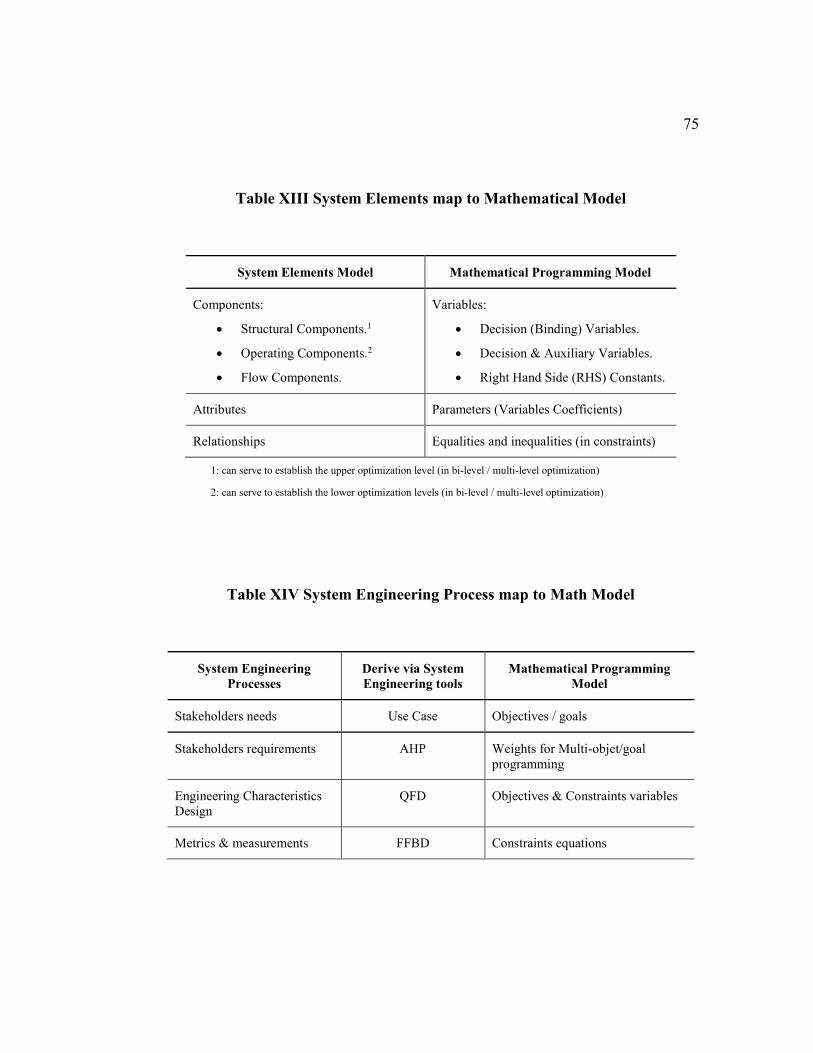
75
Table XIII System Elements map to Mathematical Model
System Elements Model Mathematical Programming Model
Components:
Structural Components.1
Operating Components.2
Flow Components.
Variables:
Decision (Binding) Variables.
Decision & Auxiliary Variables.
Right Hand Side (RHS) Constants.
Attributes Parameters (Variables Coefficients)
Relationships Equalities and inequalities (in constraints)
1: can serve to establish the upper optimization level (in bi-level / multi-level optimization)
2: can serve to establish the lower optimization levels (in bi-level / multi-level optimization)
Table XIV System Engineering Process map to Math Model
System Engineering
Processes
Derive via System
Engineering tools
Mathematical Programming
Model
Stakeholders needs Use Case Objectives / goals
Stakeholders requirements AHP Weights for Multi-objet/goal
programming
Engineering Characteristics
Design
QFD Objectives & Constraints variables
Metrics & measurements FFBD Constraints equations
76
3.1. Introduction
Generally, there are several levels of optimization decisions in plant design
and constructions. There are strategic decision levels and operational decision
levels. Examples of the former is the layout design where the decision variables
involves the flow of materials and overall topology, and the equipment designs
where the decision variables are related to the equipment duty capacity, size and
shapes. Examples of operational decision level is the pumps and compressors
efficiency, control curves of valves, and boilers maximum rating efficiency. We
are here focusing only in regards to the layout decision optimization.
Industrial equipment’s assume surrounding containers with regular
rectangular shapes. Such de facto design is presence in most of the PFDs and
P&IDs. In our model, we are assuming such shape of each equipment’s by
considering the containers shape or the convex hull. Such assumption will ensures
only rectangular shapes for situations with equal and unequal areas. Thus, to
handle other shapes like L-shaped or U-Shaped, the designer can choose to
construct sub rectangular shapes with increase weights of adjacency constraints or
flow volume or weights between such particular shapes. It is worth to emphasis
that such workaround must produce a rectangular shapes (shapes with corners of
90° and 270° angles), for the case that has different angles must increase its convex
hull size until it reaches compatibility with such angles requirements; or even
increase further to attain rectangular shapes exclusively.
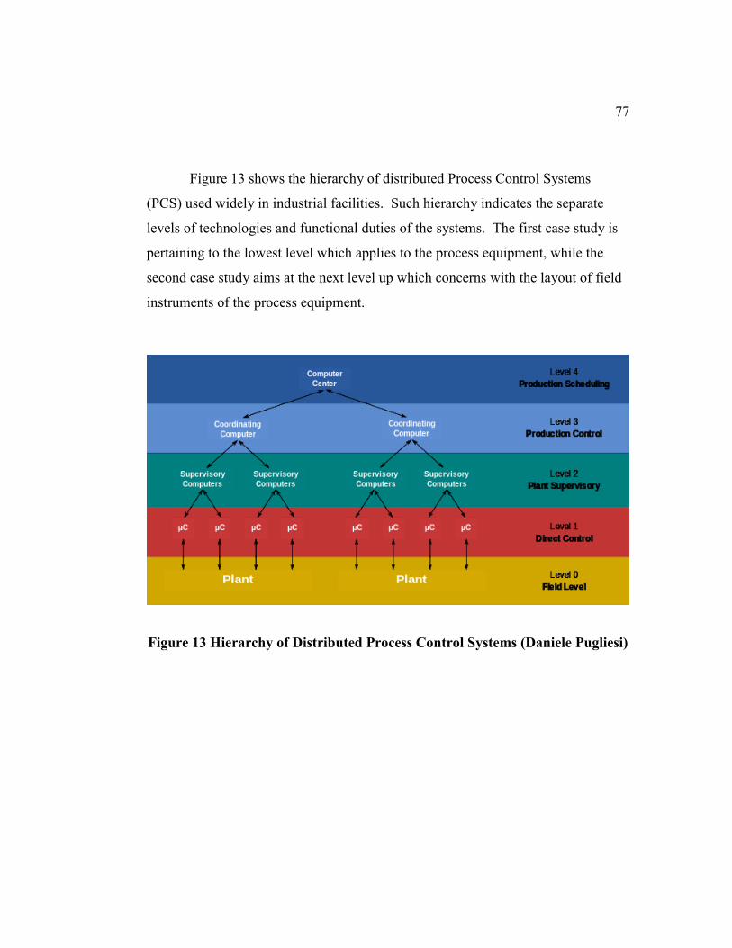
77
Figure 13 shows the hierarchy of distributed Process Control Systems
(PCS) used widely in industrial facilities. Such hierarchy indicates the separate
levels of technologies and functional duties of the systems. The first case study is
pertaining to the lowest level which applies to the process equipment, while the
second case study aims at the next level up which concerns with the layout of field
instruments of the process equipment.
Figure 13 Hierarchy of Distributed Process Control Systems (Daniele Pugliesi)
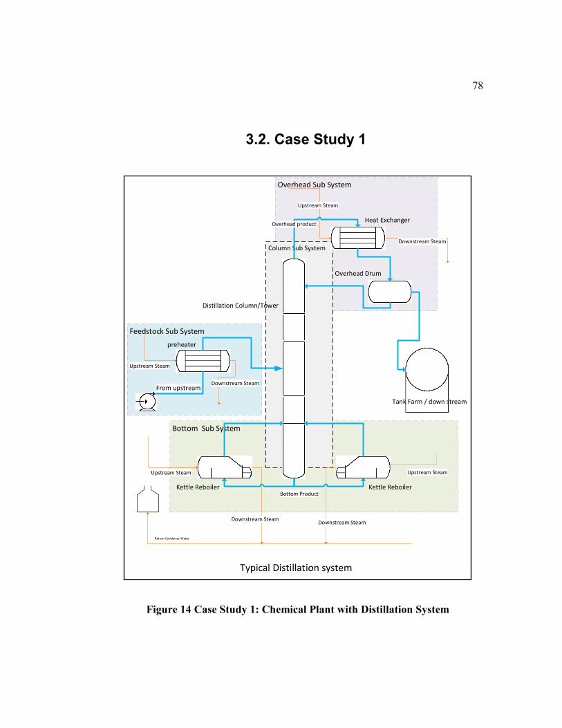
78
3.2. Case Study 1
Figure 14 Case Study 1: Chemical Plant with Distillation System
Bottom Sub System
Overhead Sub System
Feedstock Sub System
preheater
Kettle Reboiler
Column Sub System
Distillation Column/Tower
Overhead Drum
Heat Exchanger
Kettle Reboiler
From upstream
Bottom Product
Tank Farm / down stream
Typical Distillation system
Upstream Steam
Downstream Steam
Upstream Steam
Downstream Steam
Upstream Steam
Downstream SteamDownstream Steam
Upstream Steam
Return Condense Water
Overhead product
79
Typical distillation system consists of four major subsystems: Feedstock
system, Overhead system, Bottom system, and Column system; highlighted in
Figure 14 (Thomas, 2010, pp. 228–229). There are several design requirements for
industrial facilities that are mandatory. For example, Occupational Safety & Health
Act (OSHA) for process safety management, and Resource Conservation &
Recovery Act (1976). Such environment, health and safety requirements add more
stringent design specifications for industrial facilities.
3.2.1. System Concept and Definition
We are considering seven major equipment on our case study: preheater
heat exchanger, distillation column, left bottom reboiler, right bottom reboiler,
overhead finned fan heat exchanger, overhead drum, and the product tank. Among
such equipment, there are several material flow types including: liquid gas and oil,
steam, air, water, power electricity, and instrument control signals.
3.2.2. Stakeholders identification and Requirements Analysis
At the beginning in this stage, the objective is to engage stakeholders as
early as concept development and throughout the concept and design processes.
Early stakeholder involvement can help make the process more relevant to the
system scope, thereby increasing the likelihood of design utilization or scale up.
Stakeholders will have different levels of interaction with the system such as
responsibility, participation and authority.
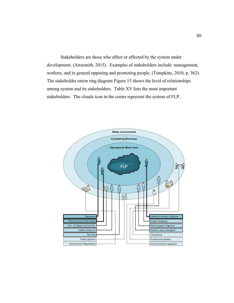
80
Stakeholders are those who affect or affected by the system under
development. (Arrasmith, 2015). Examples of stakeholders include: management,
workers, and in general opposing and promoting people. (Tompkins, 2010, p. 362).
The stakeholder onion ring diagram Figure 15 shows the level of relationships
among system and its stakeholders. Table XV lists the most important
stakeholders. The clouds icon in the center represent the system of FLP.
FLP
Operators
Maintenance Technicians
Instr. & Digital Control Sys.
Safety Inspector
Security
Public Opinion
Government Regulations
Chemical Process Engineer
Project Engineer
Plant Support Engineer
Facility Layout Designer
Competitor
Professional Bodies
Environmental regulators
Operational Work Area
Wider environment
Containing Business
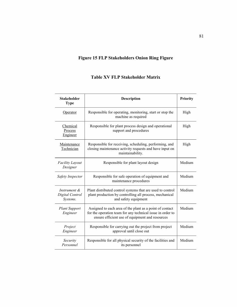
81
Figure 15 FLP Stakeholders Onion Ring Figure
Table XV FLP Stakeholder Matrix
Stakeholder
Type
Description Priority
Operator Responsible for operating, monitoring, start or stop the
machine as required
High
Chemical
Process
Engineer
Responsible for plant process design and operational
support and procedures
High
Maintenance
Technician
Responsible for receiving, scheduling, performing, and
closing maintenance activity requests and have input on
maintainability.
High
Facility Layout
Designer
Responsible for plant layout design Medium
Safety Inspector Responsible for safe operation of equipment and
maintenance procedures
Medium
Instrument &
Digital Control
Systems.
Plant distributed control systems that are used to control
plant production by controlling all process, mechanical
and safety equipment
Medium
Plant Support
Engineer
Assigned to each area of the plant as a point of contact
for the operation team for any technical issue in order to
ensure efficient use of equipment and resources
Medium
Project
Engineer
Responsible for carrying out the project from project
approval until close out
Medium
Security
Personnel
Responsible for all physical security of the facilities and
its personnel
Medium

82
The primary purpose of the Use Case is to capture the required system
behavior from the perspective of the end-user in achieving one or more desired
goals. A Use Case contains a description of the flow of events describing the
interaction between actors and the system.
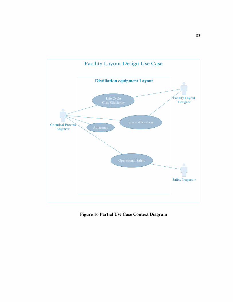
83
Figure 16 Partial Use Case Context Diagram
Chemical Process
Engineer
Facility Layout
Designer
Safety Inspector
Life Cycle
Cost Effeciency
Space Allocation
Operational Safety
Adjacency
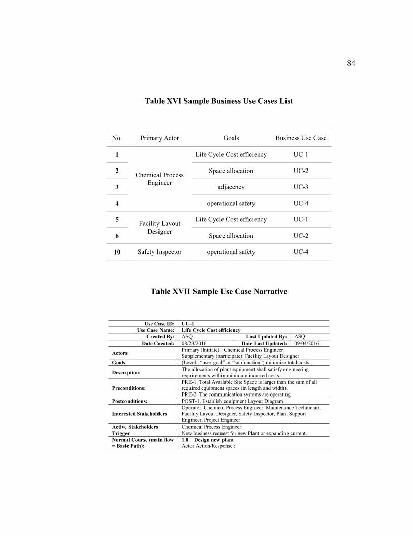
84
Table XVI Sample Business Use Cases List
No. Primary Actor Goals Business Use Case
1
Chemical Process
Engineer
Life Cycle Cost efficiency UC-1
2 Space allocation UC-2
3 adjacency UC-3
4 operational safety UC-4
5 Facility Layout
Designer
Life Cycle Cost efficiency UC-1
6 Space allocation UC-2
10 Safety Inspector operational safety UC-4
Table XVII Sample Use Case Narrative
Use Case ID: UC-1
Use Case Name: Life Cycle Cost efficiency
Created By: ASQ Last Updated By: ASQ
Date Created: 08/23/2016 Date Last Updated: 09/04/2016
Actors Primary (Initiate): Chemical Process Engineer
Supplementary (participate): Facility Layout Designer
Goals (Level : “user-goal” or “subfunction”) minimize total costs
Description: The allocation of plant equipment shall satisfy engineering
requirements within minimum incurred costs..
Preconditions:
PRE-1. Total Available Site Space is larger than the sum of all required equipment spaces (in length and width).
PRE-2. The communication systems are operating
Postconditions: POST-1. Establish equipment Layout Diagram
Interested Stakeholders
Operator, Chemical Process Engineer, Maintenance Technician, Facility Layout Designer, Safety Inspector, Plant Support
Engineer, Project Engineer
Active Stakeholders Chemical Process Engineer
Trigger New business request for new Plant or expanding current.
Normal Course (main flow
= Basic Path):
1.0 Design new plant
Actor Action/Response :
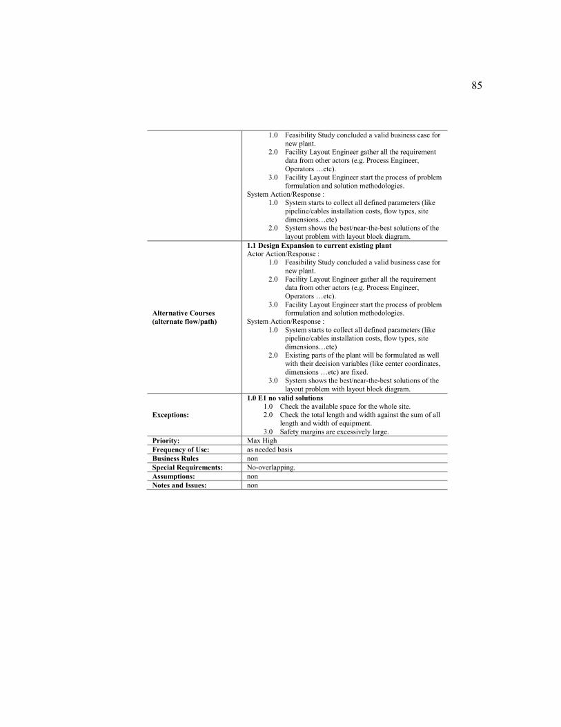
85
1.0 Feasibility Study concluded a valid business case for
new plant. 2.0 Facility Layout Engineer gather all the requirement
data from other actors (e.g. Process Engineer,
Operators …etc). 3.0 Facility Layout Engineer start the process of problem
formulation and solution methodologies.
System Action/Response : 1.0 System starts to collect all defined parameters (like
pipeline/cables installation costs, flow types, site
dimensions…etc) 2.0 System shows the best/near-the-best solutions of the
layout problem with layout block diagram.
Alternative Courses
(alternate flow/path)
1.1 Design Expansion to current existing plant
Actor Action/Response : 1.0 Feasibility Study concluded a valid business case for
new plant.
2.0 Facility Layout Engineer gather all the requirement data from other actors (e.g. Process Engineer,
Operators …etc).
3.0 Facility Layout Engineer start the process of problem formulation and solution methodologies.
System Action/Response :
1.0 System starts to collect all defined parameters (like pipeline/cables installation costs, flow types, site
dimensions…etc) 2.0 Existing parts of the plant will be formulated as well
with their decision variables (like center coordinates,
dimensions …etc) are fixed. 3.0 System shows the best/near-the-best solutions of the
layout problem with layout block diagram.
Exceptions:
1.0 E1 no valid solutions
1.0 Check the available space for the whole site. 2.0 Check the total length and width against the sum of all
length and width of equipment.
3.0 Safety margins are excessively large.
Priority: Max High
Frequency of Use: as needed basis
Business Rules non
Special Requirements: No-overlapping.
Assumptions: non
Notes and Issues: non
86
3.2.3. System Design
3.2.3.1. Customers’ & System Design Requirements
Mandatory requirements are usually results in equality constraints or
inequality constraints (opposite to optimization direction of the objective function)
in mathematical programming model. For example, no-overlap requirements will
maintain the minimum distance which means in our case here, it will be either an
equality constraint or greater-than-or-equal inequality.
MOE, measurement of effectiveness, for most of the customers’
requirements are related to Return on Investments (ROI) and maximization of
efficiency; while MOP, measurement of performance, will be generated based on
the system design requirements, see Table XVIII. Using AHP or pairwise analysis
to rank all the requirements. Such resulted ranking could be added as weights
parameters on the objective function.
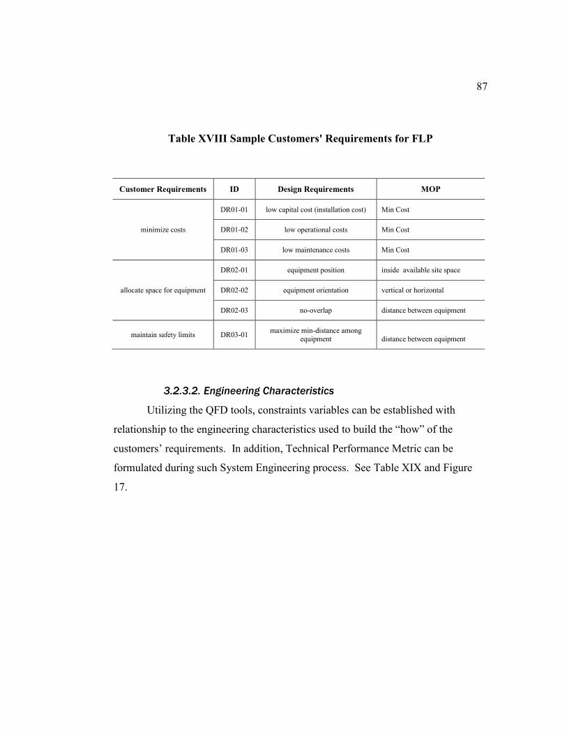
87
Table XVIII Sample Customers' Requirements for FLP
Customer Requirements ID Design Requirements MOP
minimize costs
DR01-01 low capital cost (installation cost) Min Cost
DR01-02 low operational costs Min Cost
DR01-03 low maintenance costs Min Cost
allocate space for equipment
DR02-01 equipment position inside available site space
DR02-02 equipment orientation vertical or horizontal
DR02-03 no-overlap distance between equipment
maintain safety limits DR03-01 maximize min-distance among
equipment distance between equipment
3.2.3.2. Engineering Characteristics
Utilizing the QFD tools, constraints variables can be established with
relationship to the engineering characteristics used to build the “how” of the
customers’ requirements. In addition, Technical Performance Metric can be
formulated during such System Engineering process. See Table XIX and Figure
17.
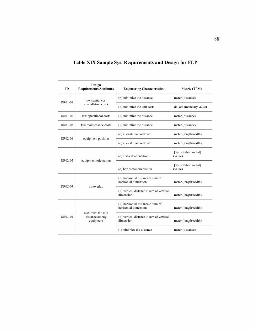
88
Table XIX Sample Sys. Requirements and Design for FLP
ID
Design
Requirements/Attributes Engineering Characteristics Metric (TPM)
DR01-01 low capital cost
(installation cost)
(+) minimize the distance meter (distance)
(+) minimize the unit costs dollars (monetary value)
DR01-02 low operational costs (+) minimize the distance meter (distance)
DR01-03 low maintenance costs (+) minimize the distance meter (distance)
DR02-01 equipment position
(o) allocate x-coordinate meter (length/width)
(o) allocate y-coordinate meter (length/width)
DR02-02 equipment orientation
(o) vertical orientation [vertical/horizontal] (value)
(o) horizontal orientation
[vertical/horizontal]
(value)
DR02-03 no-overlap
(+) horizontal distance > sum of horizontal dimension meter (length/width)
(+) vertical distance > sum of vertical
dimension meter (length/width)
DR03-01
maximize the min
distance among
equipment
(+) horizontal distance > sum of horizontal dimension meter (length/width)
(+) vertical distance > sum of vertical
dimension meter (length/width)
(-) minimize the distance meter (distance)
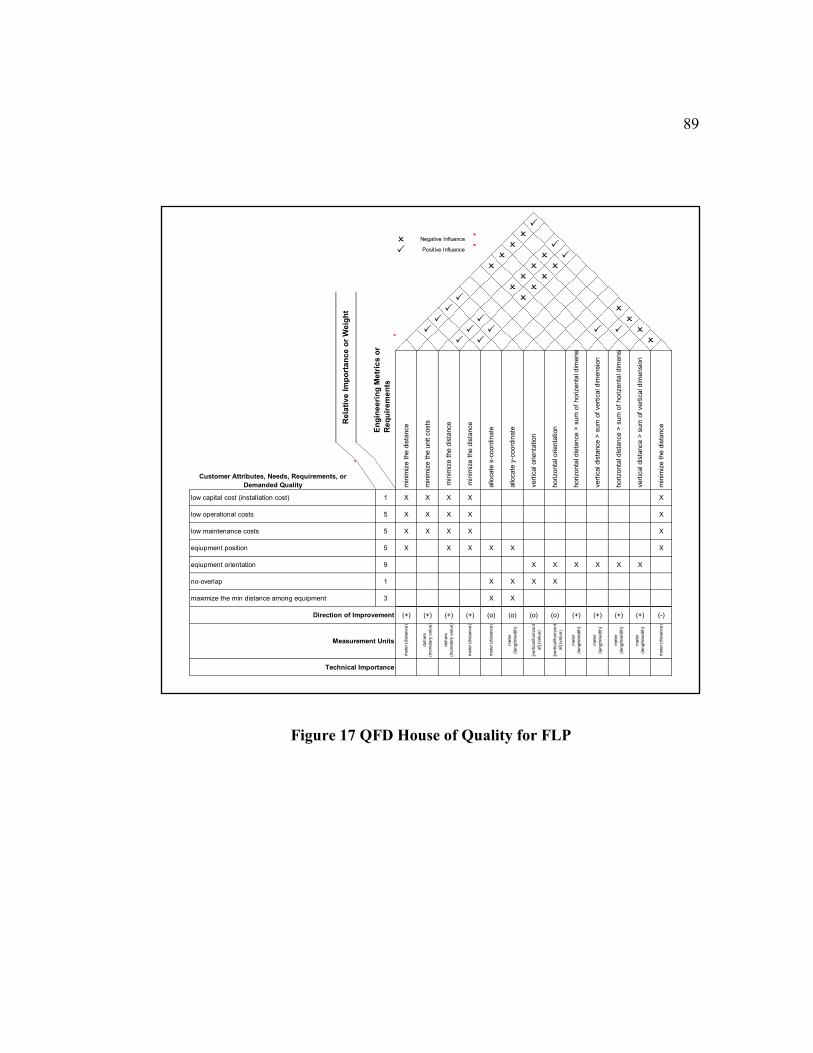
89
Figure 17 QFD House of Quality for FLP
P
OO Negative Influence
O PP Positive Influence
O O P
O
O O
O O
OO
P
En
gin
ee
rin
g M
etr
ics
or
Re
qu
ire
me
nts
P P
O
P O
P P
P P P P P O
O
O
min
imiz
e t
he d
ista
nce
horizonta
l dis
tance >
sum
of
horizenta
l dim
ensio
n
min
imiz
e t
he d
ista
nce
min
imiz
e t
he u
nit c
osts
min
imiz
e t
he d
ista
nce
min
imiz
e t
he d
ista
nce
allo
cate
x-c
oord
inate
allo
cate
y-c
oord
inate
vert
ical orienta
tion
vert
ical dis
tance >
sum
of
vert
ical dim
ensio
n
low capital cost (installation cost) 1 X X
horizonta
l orienta
tion
horizonta
l dis
tance >
sum
of
horizenta
l dim
ensio
n
vert
ical dis
tance >
sum
of
vert
ical dim
ensio
n
X
low operational costs 5 X X
X X
X
low maintenance costs 5 X X
X X
X
eqiupment position 5 X
X X
X
eqiupment orientation 9
X X X X
X X X X
no-overlap 1
X X
X X
maximize the min distance among equipment 3
X X
X X
(+) (+)(+) (+) (o) (o) (o) (o) (+) (-)Direction of Improvement (+) (+)
Measurement Units
do
lla
rs
(mo
ne
tary
va
lue
)
me
ter
(dis
tan
ce
)
(+)
[ve
rtic
al/h
ori
zo
nt
al] (
va
lue
)
Customer Attributes, Needs, Requirements, or
Demanded Quality
Technical Importance
Re
lati
ve
Im
po
rta
nc
e o
r W
eig
ht
[ve
rtic
al/h
ori
zo
nt
al] (
va
lue
)
me
ter
(le
ng
th/w
idth
)
me
ter
(le
ng
th/w
idth
)
do
lla
rs
(mo
ne
tary
va
lue
)
me
ter
(dis
tan
ce
)
me
ter
(dis
tan
ce
)
me
ter
(le
ng
th/w
idth
)
me
ter
(le
ng
th/w
idth
)
me
ter
(le
ng
th/w
idth
)
me
ter
(dis
tan
ce
)
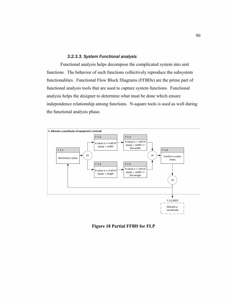
90
3.2.3.3. System Functional analysis
Functional analysis helps decompose the complicated system into unit
functions. The behavior of such functions collectively reproduce the subsystem
functionalities. Functional Flow Block Diagrams (FFBDs) are the prime part of
functional analysis tools that are used to capture system functions. Functional
analysis helps the designer to determine what must be done which ensure
independence relationship among functions. N-square tools is used as well during
the functional analysis phase.
Figure 18 Partial FFBD for FLP
F 2.0 [REF]
1. Allocate x-coordinate of equipment i centroid
Nominate x value
X-value is >= half of equip. i. width
OR
X-value is >= half of equip. i. length
X-value is + half of equip. i. width <=
Site width
X-value is + half of equip. i. width <=
Site length
OR Confirm x-value limits
OR
Allocate y-coordinate
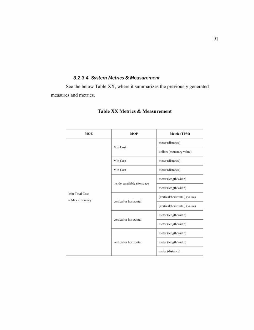
91
3.2.3.4. System Metrics & Measurement
See the below Table XX, where it summarizes the previously generated
measures and metrics.
Table XX Metrics & Measurement
MOE MOP Metric (TPM)
Min Total Cost
= Max efficiency
Min Cost
meter (distance)
dollars (monetary value)
Min Cost meter (distance)
Min Cost meter (distance)
inside available site space
meter (length/width)
meter (length/width)
vertical or horizontal
[vertical/horizontal] (value)
[vertical/horizontal] (value)
vertical or horizontal
meter (length/width)
meter (length/width)
vertical or horizontal
meter (length/width)
meter (length/width)
meter (distance)
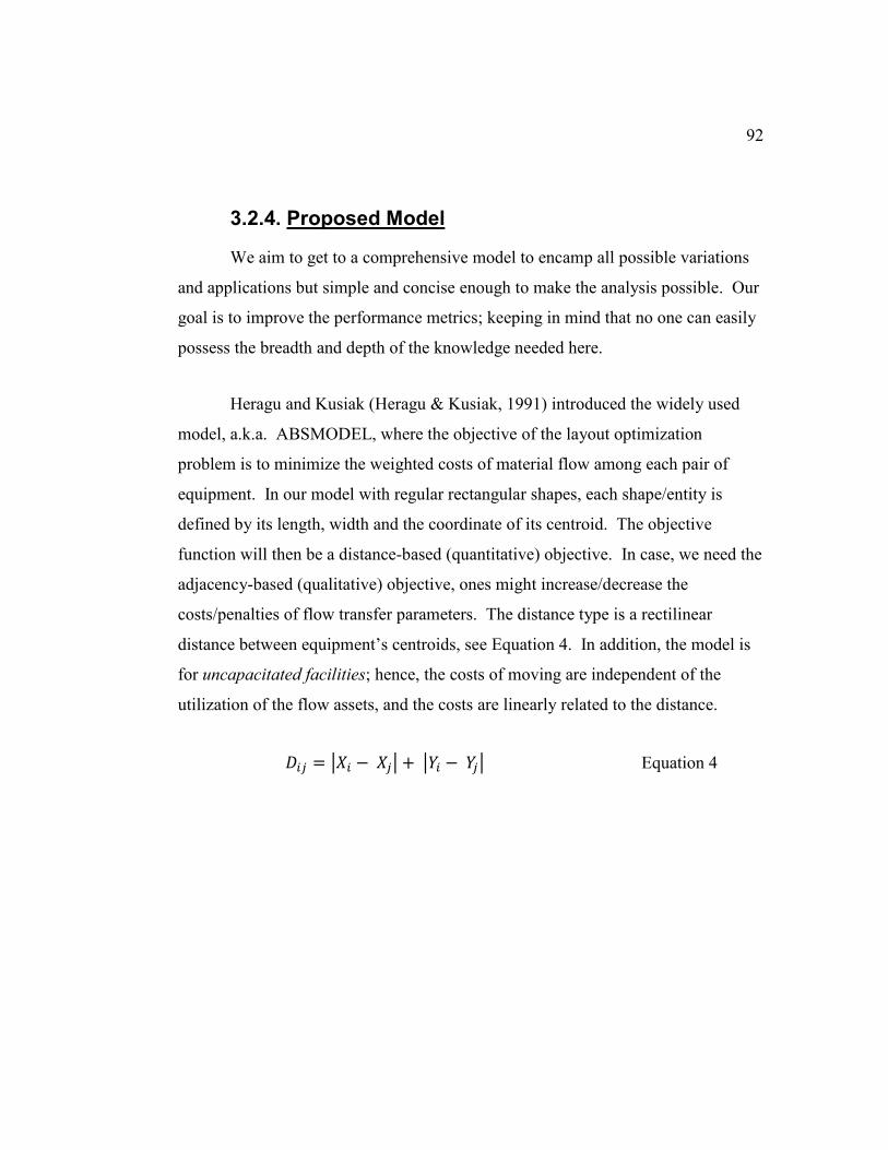
92
3.2.4. Proposed Model
We aim to get to a comprehensive model to encamp all possible variations
and applications but simple and concise enough to make the analysis possible. Our
goal is to improve the performance metrics; keeping in mind that no one can easily
possess the breadth and depth of the knowledge needed here.
Heragu and Kusiak (Heragu & Kusiak, 1991) introduced the widely used
model, a.k.a. ABSMODEL, where the objective of the layout optimization
problem is to minimize the weighted costs of material flow among each pair of
equipment. In our model with regular rectangular shapes, each shape/entity is
defined by its length, width and the coordinate of its centroid. The objective
function will then be a distance-based (quantitative) objective. In case, we need the
adjacency-based (qualitative) objective, ones might increase/decrease the
costs/penalties of flow transfer parameters. The distance type is a rectilinear
distance between equipment’s centroids, see Equation 4. In addition, the model is
for uncapacitated facilities; hence, the costs of moving are independent of the
utilization of the flow assets, and the costs are linearly related to the distance.
𝐷𝑖𝑗 = |𝑋𝑖 − 𝑋𝑗| + |𝑌𝑖 − 𝑌𝑗| Equation 4
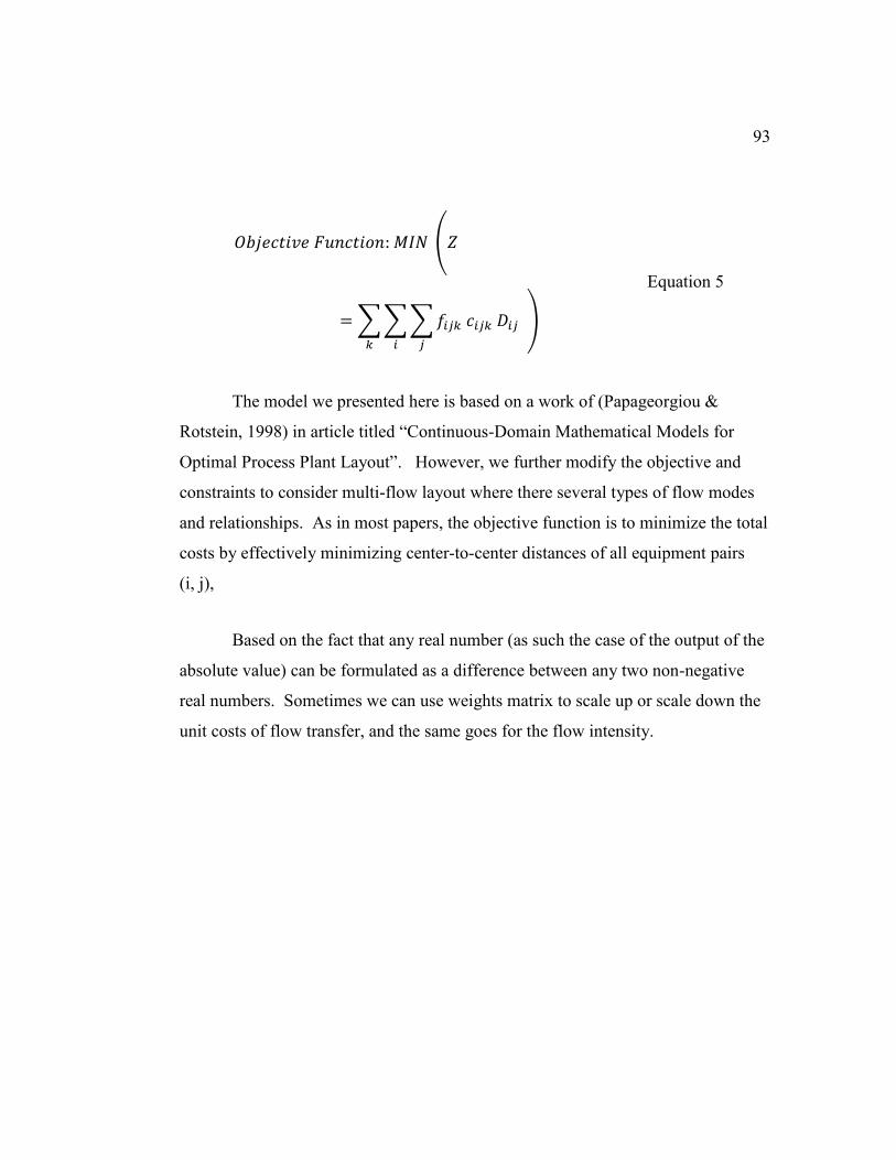
93
𝑂𝑏𝑗𝑒𝑐𝑡𝑖𝑣𝑒 𝐹𝑢𝑛𝑐𝑡𝑖𝑜𝑛: 𝑀𝐼𝑁 (𝑍
= ∑ ∑ ∑ 𝑓𝑖𝑗𝑘 𝑐𝑖𝑗𝑘 𝐷𝑖𝑗
𝑗𝑖𝑘
)
Equation 5
The model we presented here is based on a work of (Papageorgiou &
Rotstein, 1998) in article titled “Continuous-Domain Mathematical Models for
Optimal Process Plant Layout”. However, we further modify the objective and
constraints to consider multi-flow layout where there several types of flow modes
and relationships. As in most papers, the objective function is to minimize the total
costs by effectively minimizing center-to-center distances of all equipment pairs
(i, j),
Based on the fact that any real number (as such the case of the output of the
absolute value) can be formulated as a difference between any two non-negative
real numbers. Sometimes we can use weights matrix to scale up or scale down the
unit costs of flow transfer, and the same goes for the flow intensity.
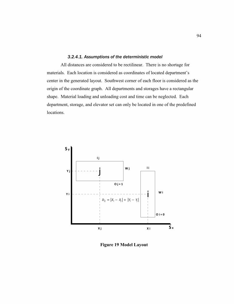
94
3.2.4.1. Assumptions of the deterministic model
All distances are considered to be rectilinear. There is no shortage for
materials. Each location is considered as coordinates of located department’s
center in the generated layout. Southwest corner of each floor is considered as the
origin of the coordinate graph. All departments and storages have a rectangular
shape. Material loading and unloading cost and time can be neglected. Each
department, storage, and elevator set can only be located in one of the predefined
locations.
Figure 19 Model Layout
j
i
X j X i
Y i
Y j
l j
W j l i
W i
S x
S y
O j = 1
O i = 0
𝐷𝑖𝑗 = |𝑋𝑖 − 𝑋𝑗 | + |𝑌𝑖 − 𝑌𝑗 |
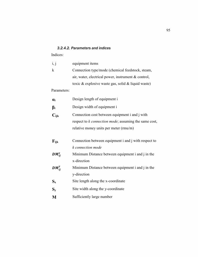
95
3.2.4.2. Parameters and indices
Indices:
i, j equipment items
k Connection type/mode (chemical feedstock, steam,
air, water, electrical power, instrument & control,
toxic & explosive waste gas, solid & liquid waste)
Parameters:
αi Design length of equipment i
βi Design width of equipment i
Cijk Connection cost between equipment i and j with
respect to k connection mode; assuming the same cost,
relative money units per meter (rmu/m)
Fijk Connection between equipment i and j with respect to
k connection mode
𝑫𝑴𝒊𝒋𝒙 Minimum Distance between equipment i and j in the
x-direction
𝑫𝑴𝒊𝒋𝒚
Minimum Distance between equipment i and j in the
y-direction
Sx Site length along the x-coordinate
Sy Site width along the y-coordinate
M Sufficiently large number
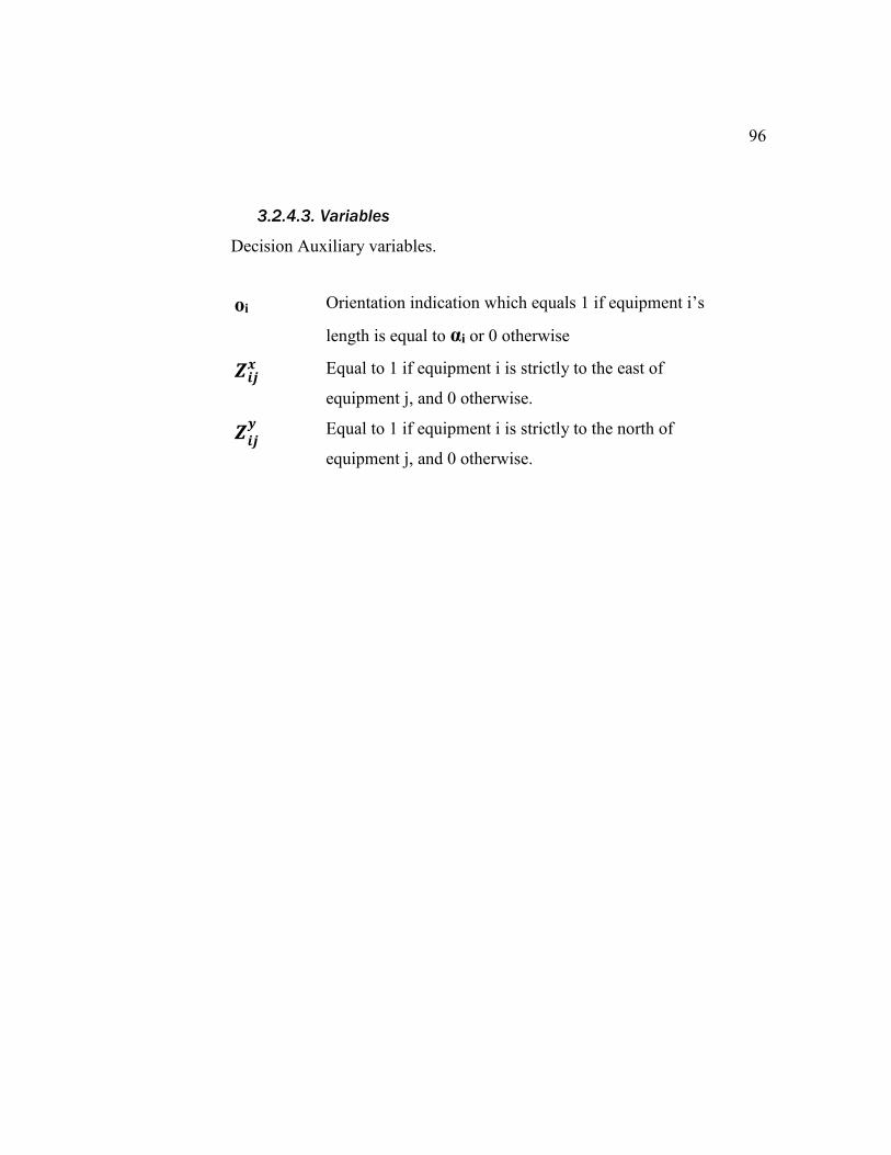
96
3.2.4.3. Variables
Decision Auxiliary variables.
oi Orientation indication which equals 1 if equipment i’s
length is equal to αi or 0 otherwise
𝒁𝒊𝒋𝒙
Equal to 1 if equipment i is strictly to the east of
equipment j, and 0 otherwise.
𝒁𝒊𝒋𝒚
Equal to 1 if equipment i is strictly to the north of
equipment j, and 0 otherwise.
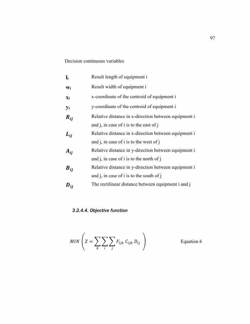
97
Decision continuous variables
li Result length of equipment i
wi Result width of equipment i
xi x-coordinate of the centroid of equipment i
yi y-coordinate of the centroid of equipment i
𝑹𝒊𝒋 Relative distance in x-direction between equipment i
and j, in case of i is to the east of j
𝑳𝒊𝒋 Relative distance in x-direction between equipment i
and j, in case of i is to the west of j
𝑨𝒊𝒋 Relative distance in y-direction between equipment i
and j, in case of i is to the north of j
𝑩𝒊𝒋 Relative distance in y-direction between equipment i
and j, in case of i is to the south of j
𝑫𝒊𝒋 The rectilinear distance between equipment i and j
3.2.4.4. Objective function
𝑀𝐼𝑁 (𝑍 = ∑ ∑ ∑ 𝐹𝑖𝑗𝑘 𝐶𝑖𝑗𝑘 𝐷𝑖𝑗
𝑗𝑖𝑘
) Equation 6
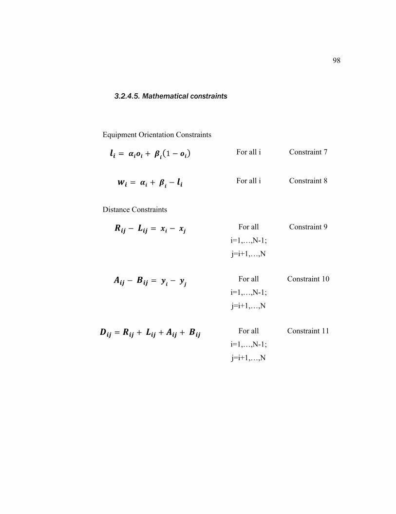
98
3.2.4.5. Mathematical constraints
Equipment Orientation Constraints
𝒍𝒊 = 𝜶𝒊𝒐𝒊 + 𝜷𝒊(1 − 𝒐𝒊) For all i Constraint 7
𝒘𝒊 = 𝜶𝒊 + 𝜷𝒊
− 𝒍𝒊 For all i Constraint 8
Distance Constraints
𝑹𝒊𝒋 − 𝑳𝒊𝒋 = 𝒙𝒊 − 𝒙𝒋 For all
i=1,…,N-1;
j=i+1,…,N
Constraint 9
𝑨𝒊𝒋 − 𝑩𝒊𝒋 = 𝒚𝒊
− 𝒚𝒋 For all
i=1,…,N-1;
j=i+1,…,N
Constraint 10
𝑫𝒊𝒋 = 𝑹𝒊𝒋 + 𝑳𝒊𝒋 + 𝑨𝒊𝒋 + 𝑩𝒊𝒋 For all
i=1,…,N-1;
j=i+1,…,N
Constraint 11

99
Non-overlapping Constraints
𝒙𝒊 − 𝒙𝒋 + 𝑴( 1 − 𝒁𝒊𝒋𝒙
)
≥ 𝒍𝒊 + 𝒍𝒋
𝟐+ 𝑫𝑴𝒊𝒋
𝒙
For all i; j ≠ i Constraint 12
𝒚𝒊 − 𝒚𝒋 + 𝑴( 1 − 𝒁𝒊𝒋𝒚
)
≥ 𝒘𝒊 + 𝒘𝒋
𝟐+ 𝑫𝑴𝒊𝒋
𝒚
For all i; j ≠ i Constraint 13
𝒁𝒊𝒋𝒙
+ 𝒁𝒋𝒊𝒙
+ 𝒁𝒊𝒋𝒚
+ 𝒁𝒋𝒊𝒚
≥ 𝟏 For all
i=1,…,N-1;
j=i+1,…,N
Constraint 14
𝒁𝒊𝒋𝒙
+ 𝒁𝒋𝒊𝒙
≤ 𝟏 For all
i=1,…,N-1;
j=i+1,…,N
Constraint 15
𝒁𝒊𝒋𝒚
+ 𝒁𝒋𝒊𝒚
≤ 𝟏 For all
i=1,…,N-1;
j=i+1,…,N
Constraint 16
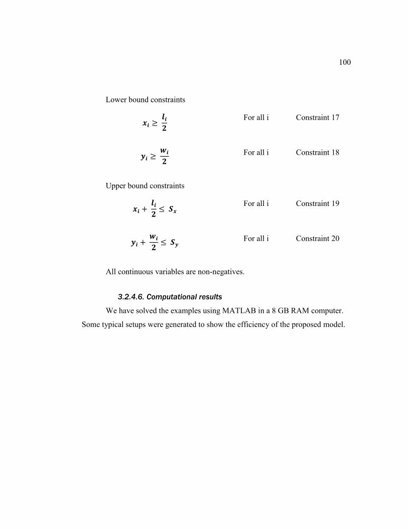
100
Lower bound constraints
𝒙𝒊 ≥ 𝒍𝒊
𝟐
For all i Constraint 17
𝒚𝒊 ≥ 𝒘𝒊
𝟐
For all i Constraint 18
Upper bound constraints
𝒙𝒊 + 𝒍𝒊
𝟐≤ 𝑺𝒙
For all i Constraint 19
𝒚𝒊 + 𝒘𝒊
𝟐≤ 𝑺𝒚
For all i Constraint 20
All continuous variables are non-negatives.
3.2.4.6. Computational results
We have solved the examples using MATLAB in a 8 GB RAM computer.
Some typical setups were generated to show the efficiency of the proposed model.
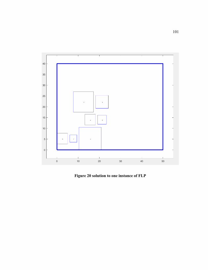
101
Figure 20 solution to one instance of FLP
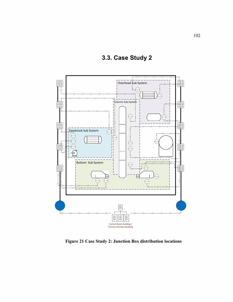
102
3.3. Case Study 2
Figure 21 Case Study 2: Junction Box distribution locations
Bottom Sub System
Overhead Sub System
Feedstock Sub System
Column Sub System
Control Room Building / Process Interface Building
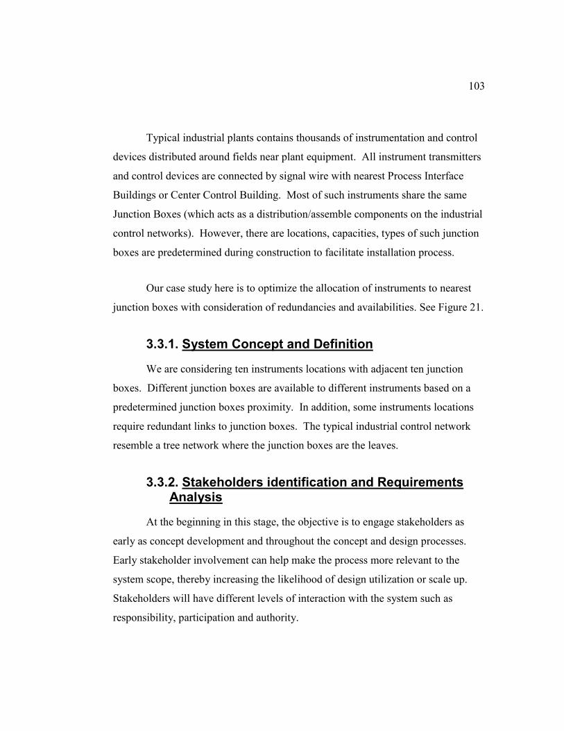
103
Typical industrial plants contains thousands of instrumentation and control
devices distributed around fields near plant equipment. All instrument transmitters
and control devices are connected by signal wire with nearest Process Interface
Buildings or Center Control Building. Most of such instruments share the same
Junction Boxes (which acts as a distribution/assemble components on the industrial
control networks). However, there are locations, capacities, types of such junction
boxes are predetermined during construction to facilitate installation process.
Our case study here is to optimize the allocation of instruments to nearest
junction boxes with consideration of redundancies and availabilities. See Figure 21.
3.3.1. System Concept and Definition
We are considering ten instruments locations with adjacent ten junction
boxes. Different junction boxes are available to different instruments based on a
predetermined junction boxes proximity. In addition, some instruments locations
require redundant links to junction boxes. The typical industrial control network
resemble a tree network where the junction boxes are the leaves.
3.3.2. Stakeholders identification and Requirements Analysis
At the beginning in this stage, the objective is to engage stakeholders as
early as concept development and throughout the concept and design processes.
Early stakeholder involvement can help make the process more relevant to the
system scope, thereby increasing the likelihood of design utilization or scale up.
Stakeholders will have different levels of interaction with the system such as
responsibility, participation and authority.
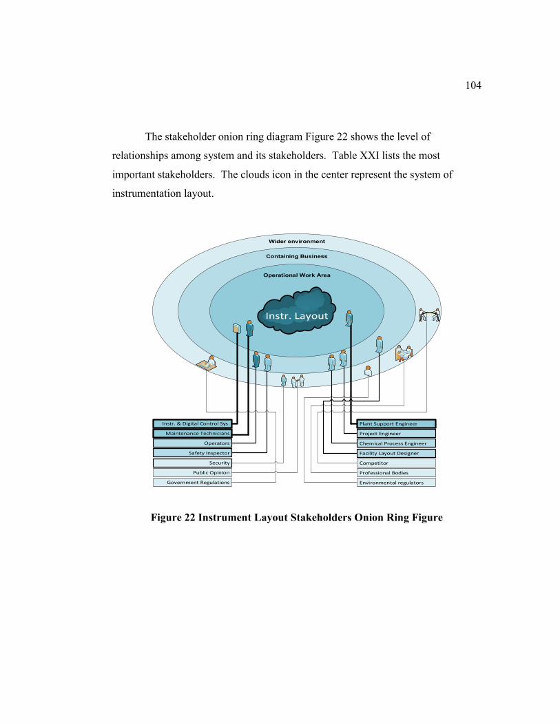
104
The stakeholder onion ring diagram Figure 22 shows the level of
relationships among system and its stakeholders. Table XXI lists the most
important stakeholders. The clouds icon in the center represent the system of
instrumentation layout.
Figure 22 Instrument Layout Stakeholders Onion Ring Figure
Instr. Layout
Instr. & Digital Control Sys.
Maintenance Technicians
Operators
Safety Inspector
Security
Public Opinion
Government Regulations
Plant Support Engineer
Project Engineer
Chemical Process Engineer
Facility Layout Designer
Competitor
Professional Bodies
Environmental regulators
Operational Work Area
Wider environment
Containing Business
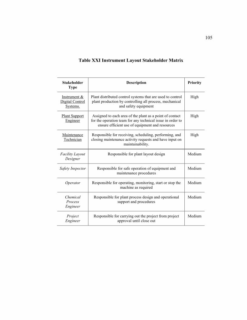
105
Table XXI Instrument Layout Stakeholder Matrix
Stakeholder
Type
Description Priority
Instrument &
Digital Control
Systems.
Plant distributed control systems that are used to control
plant production by controlling all process, mechanical
and safety equipment
High
Plant Support
Engineer
Assigned to each area of the plant as a point of contact
for the operation team for any technical issue in order to
ensure efficient use of equipment and resources
High
Maintenance
Technician
Responsible for receiving, scheduling, performing, and
closing maintenance activity requests and have input on
maintainability.
High
Facility Layout
Designer
Responsible for plant layout design Medium
Safety Inspector Responsible for safe operation of equipment and
maintenance procedures
Medium
Operator Responsible for operating, monitoring, start or stop the
machine as required
Medium
Chemical
Process
Engineer
Responsible for plant process design and operational
support and procedures
Medium
Project
Engineer
Responsible for carrying out the project from project
approval until close out
Medium
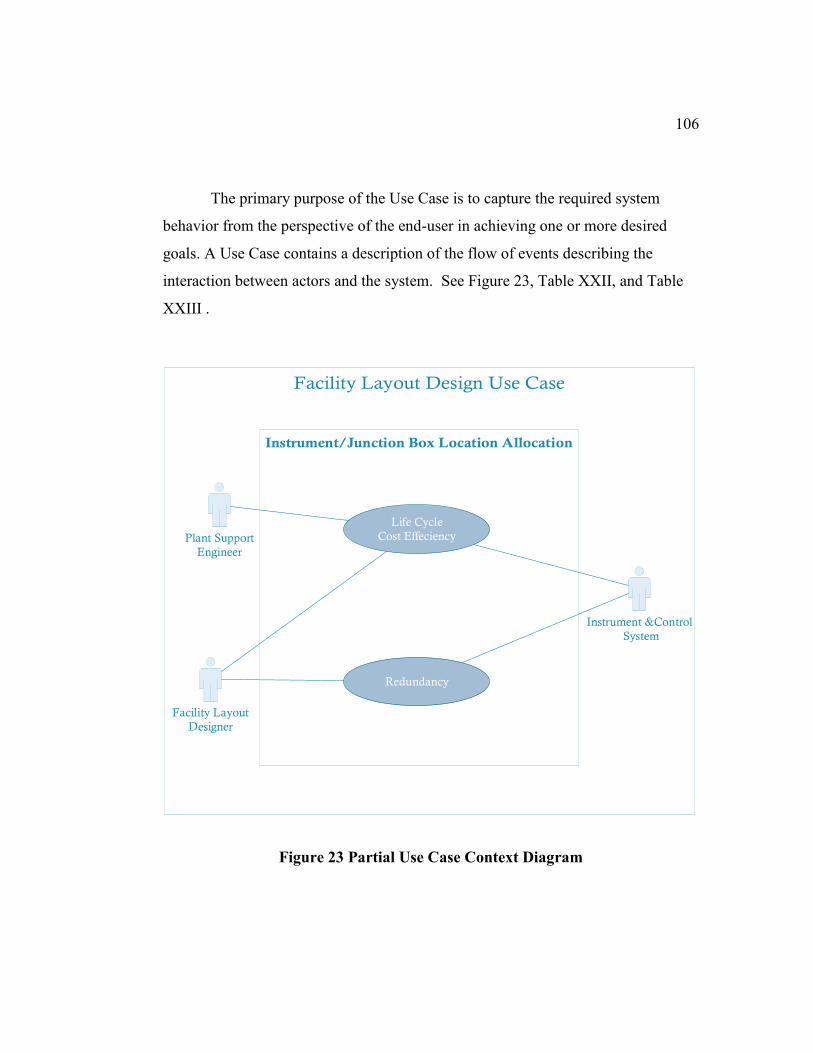
106
The primary purpose of the Use Case is to capture the required system
behavior from the perspective of the end-user in achieving one or more desired
goals. A Use Case contains a description of the flow of events describing the
interaction between actors and the system. See Figure 23, Table XXII, and Table
XXIII .
Figure 23 Partial Use Case Context Diagram
Instrument &Control
System
Facility Layout
Designer
Plant Support
Engineer
Life Cycle
Cost Effeciency
Redundancy
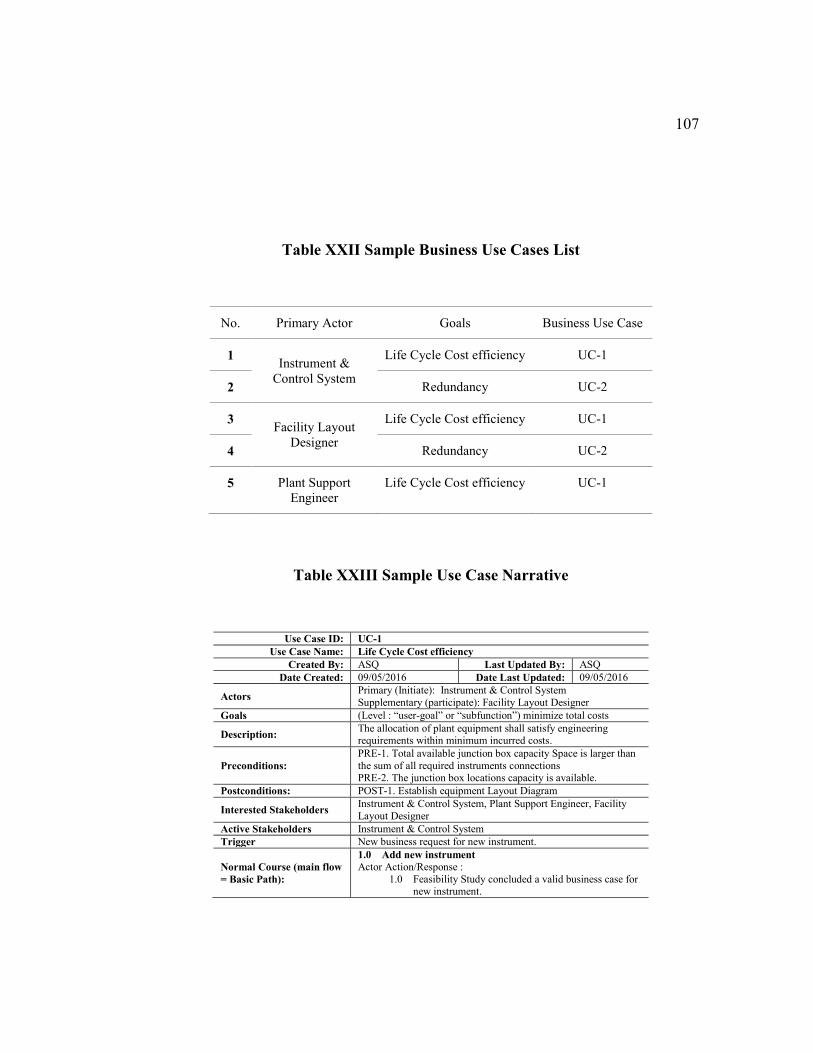
107
Table XXII Sample Business Use Cases List
No. Primary Actor Goals Business Use Case
1 Instrument &
Control System
Life Cycle Cost efficiency UC-1
2 Redundancy UC-2
3 Facility Layout
Designer
Life Cycle Cost efficiency UC-1
4 Redundancy UC-2
5 Plant Support
Engineer
Life Cycle Cost efficiency UC-1
Table XXIII Sample Use Case Narrative
Use Case ID: UC-1
Use Case Name: Life Cycle Cost efficiency
Created By: ASQ Last Updated By: ASQ
Date Created: 09/05/2016 Date Last Updated: 09/05/2016
Actors Primary (Initiate): Instrument & Control System
Supplementary (participate): Facility Layout Designer
Goals (Level : “user-goal” or “subfunction”) minimize total costs
Description: The allocation of plant equipment shall satisfy engineering requirements within minimum incurred costs.
Preconditions:
PRE-1. Total available junction box capacity Space is larger than
the sum of all required instruments connections
PRE-2. The junction box locations capacity is available.
Postconditions: POST-1. Establish equipment Layout Diagram
Interested Stakeholders Instrument & Control System, Plant Support Engineer, Facility
Layout Designer
Active Stakeholders Instrument & Control System
Trigger New business request for new instrument.
Normal Course (main flow
= Basic Path):
1.0 Add new instrument
Actor Action/Response :
1.0 Feasibility Study concluded a valid business case for new instrument.
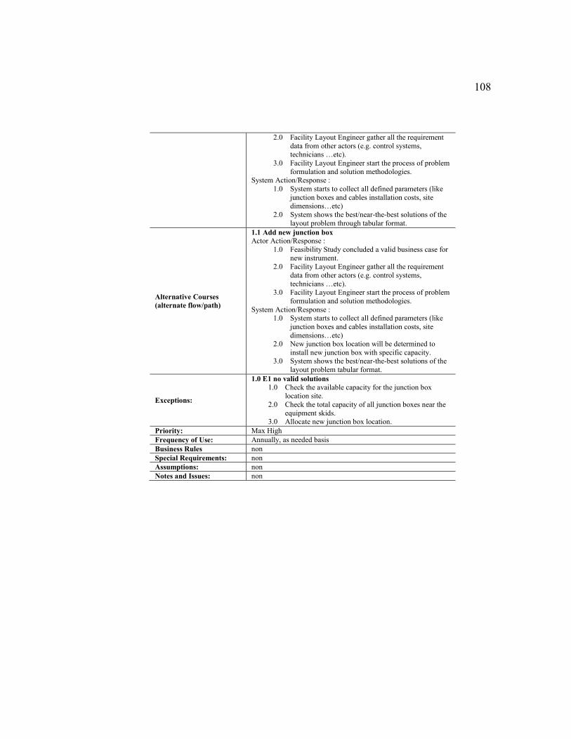
108
2.0 Facility Layout Engineer gather all the requirement
data from other actors (e.g. control systems, technicians …etc).
3.0 Facility Layout Engineer start the process of problem
formulation and solution methodologies. System Action/Response :
1.0 System starts to collect all defined parameters (like
junction boxes and cables installation costs, site dimensions…etc)
2.0 System shows the best/near-the-best solutions of the
layout problem through tabular format.
Alternative Courses
(alternate flow/path)
1.1 Add new junction box
Actor Action/Response :
1.0 Feasibility Study concluded a valid business case for
new instrument. 2.0 Facility Layout Engineer gather all the requirement
data from other actors (e.g. control systems,
technicians …etc). 3.0 Facility Layout Engineer start the process of problem
formulation and solution methodologies.
System Action/Response : 1.0 System starts to collect all defined parameters (like
junction boxes and cables installation costs, site
dimensions…etc) 2.0 New junction box location will be determined to
install new junction box with specific capacity. 3.0 System shows the best/near-the-best solutions of the
layout problem tabular format.
Exceptions:
1.0 E1 no valid solutions
1.0 Check the available capacity for the junction box
location site.
2.0 Check the total capacity of all junction boxes near the
equipment skids. 3.0 Allocate new junction box location.
Priority: Max High
Frequency of Use: Annually, as needed basis
Business Rules non
Special Requirements: non
Assumptions: non
Notes and Issues: non
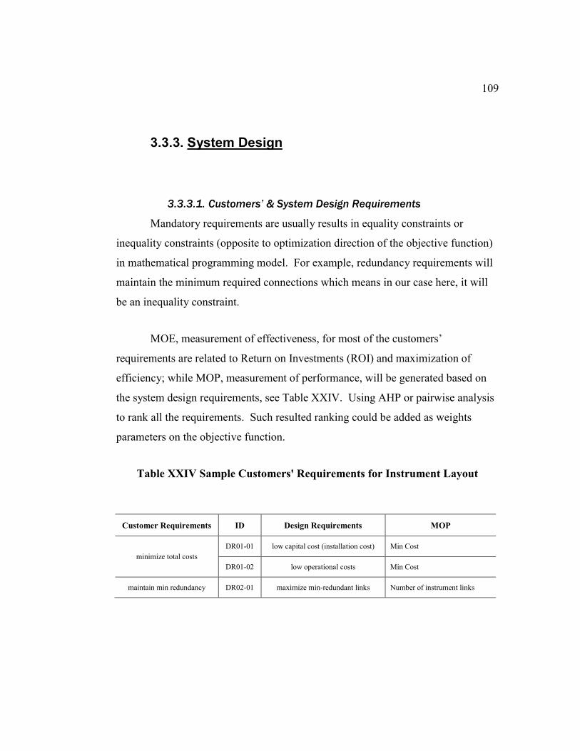
109
3.3.3. System Design
3.3.3.1. Customers’ & System Design Requirements
Mandatory requirements are usually results in equality constraints or
inequality constraints (opposite to optimization direction of the objective function)
in mathematical programming model. For example, redundancy requirements will
maintain the minimum required connections which means in our case here, it will
be an inequality constraint.
MOE, measurement of effectiveness, for most of the customers’
requirements are related to Return on Investments (ROI) and maximization of
efficiency; while MOP, measurement of performance, will be generated based on
the system design requirements, see Table XXIV. Using AHP or pairwise analysis
to rank all the requirements. Such resulted ranking could be added as weights
parameters on the objective function.
Table XXIV Sample Customers' Requirements for Instrument Layout
Customer Requirements ID Design Requirements MOP
minimize total costs
DR01-01 low capital cost (installation cost) Min Cost
DR01-02 low operational costs Min Cost
maintain min redundancy DR02-01 maximize min-redundant links Number of instrument links
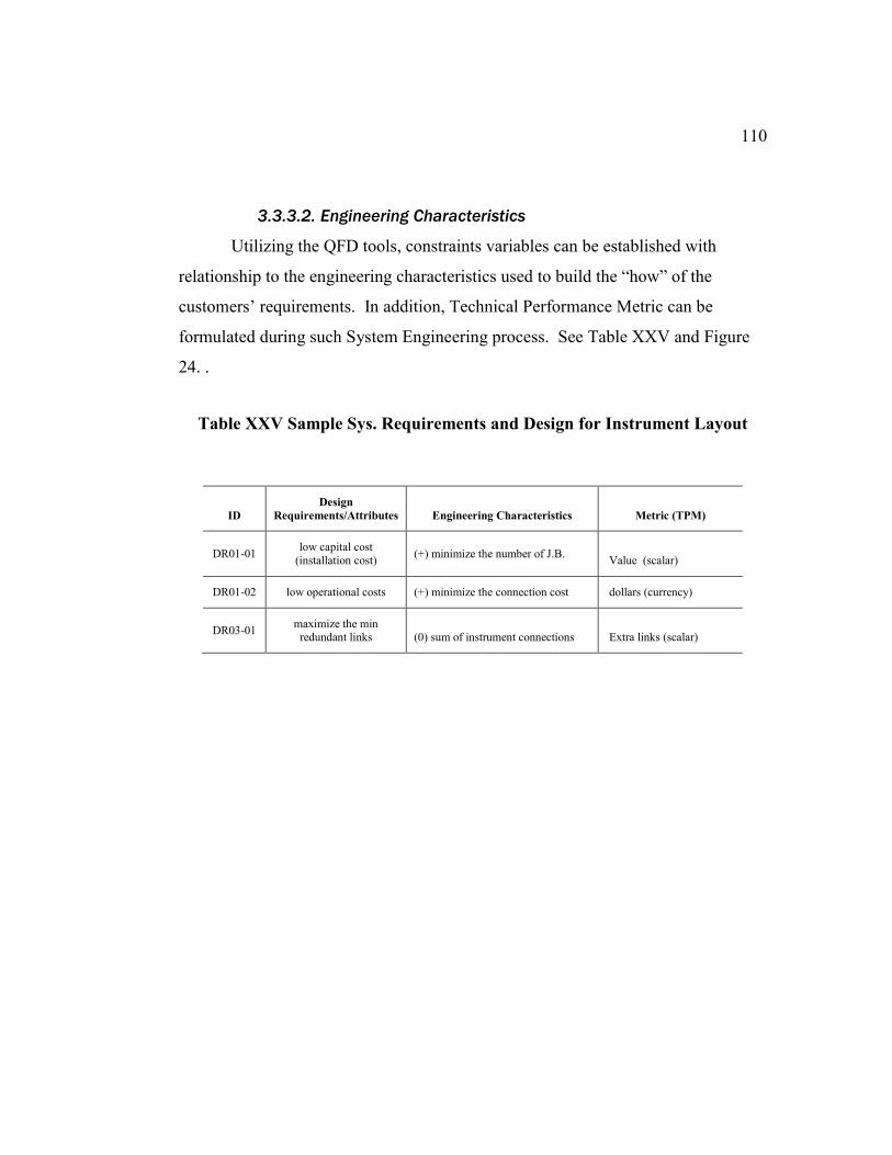
110
3.3.3.2. Engineering Characteristics
Utilizing the QFD tools, constraints variables can be established with
relationship to the engineering characteristics used to build the “how” of the
customers’ requirements. In addition, Technical Performance Metric can be
formulated during such System Engineering process. See Table XXV and Figure
24. .
Table XXV Sample Sys. Requirements and Design for Instrument Layout
ID
Design
Requirements/Attributes Engineering Characteristics Metric (TPM)
DR01-01 low capital cost
(installation cost) (+) minimize the number of J.B.
Value (scalar)
DR01-02 low operational costs (+) minimize the connection cost dollars (currency)
DR03-01 maximize the min
redundant links (0) sum of instrument connections Extra links (scalar)
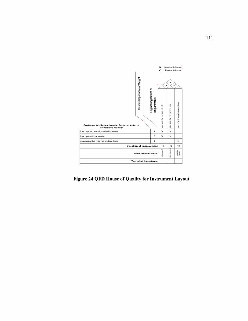
111
Figure 24 QFD House of Quality for Instrument Layout
O Negative Influence
P Positive Influence
Eng
inee
ring
Met
rics
or
Req
uire
men
ts
O P
O
min
imiz
e th
e nu
mbe
r of
J.B
.
min
imiz
e th
e co
nnec
tion
cost
sum
of i
nstr
umen
t con
nect
ions
low capital cost (installation cost) 1 X X
low operational costs 5 X X
maximize the min redundant links 1 X
(+)Direction of Improvement (+) (+)
Measurement Units
dol
lar (
curr
ency
)
val
ue (s
cala
r)
Customer Attributes, Needs, Requirements, or
Demanded Quality
Technical Importance
Rel
ativ
e Im
port
ance
or
Wei
ght
ext
ra li
nks
(sca
lar)
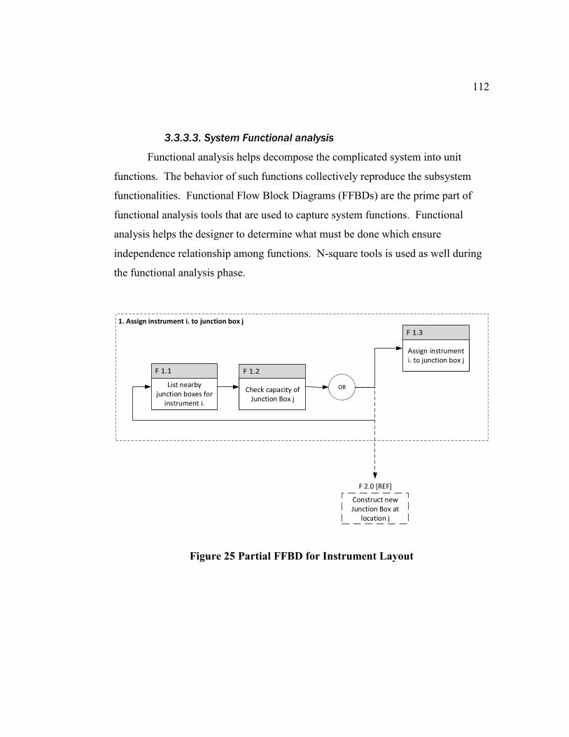
112
3.3.3.3. System Functional analysis
Functional analysis helps decompose the complicated system into unit
functions. The behavior of such functions collectively reproduce the subsystem
functionalities. Functional Flow Block Diagrams (FFBDs) are the prime part of
functional analysis tools that are used to capture system functions. Functional
analysis helps the designer to determine what must be done which ensure
independence relationship among functions. N-square tools is used as well during
the functional analysis phase.
Figure 25 Partial FFBD for Instrument Layout
F 2.0 [REF]
1. Assign instrument i. to junction box j
List nearby junction boxes for
instrument i.
Check capacity of Junction Box j
Assign instrument i. to junction box j
OR
Construct new Junction Box at
location j
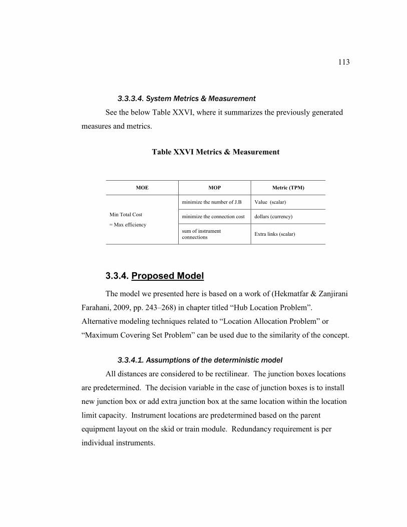
113
3.3.3.4. System Metrics & Measurement
See the below Table XXVI, where it summarizes the previously generated
measures and metrics.
Table XXVI Metrics & Measurement
MOE MOP Metric (TPM)
Min Total Cost
= Max efficiency
minimize the number of J.B Value (scalar)
minimize the connection cost dollars (currency)
sum of instrument
connections Extra links (scalar)
3.3.4. Proposed Model
The model we presented here is based on a work of (Hekmatfar & Zanjirani
Farahani, 2009, pp. 243–268) in chapter titled “Hub Location Problem”.
Alternative modeling techniques related to “Location Allocation Problem” or
“Maximum Covering Set Problem” can be used due to the similarity of the concept.
3.3.4.1. Assumptions of the deterministic model
All distances are considered to be rectilinear. The junction boxes locations
are predetermined. The decision variable in the case of junction boxes is to install
new junction box or add extra junction box at the same location within the location
limit capacity. Instrument locations are predetermined based on the parent
equipment layout on the skid or train module. Redundancy requirement is per
individual instruments.
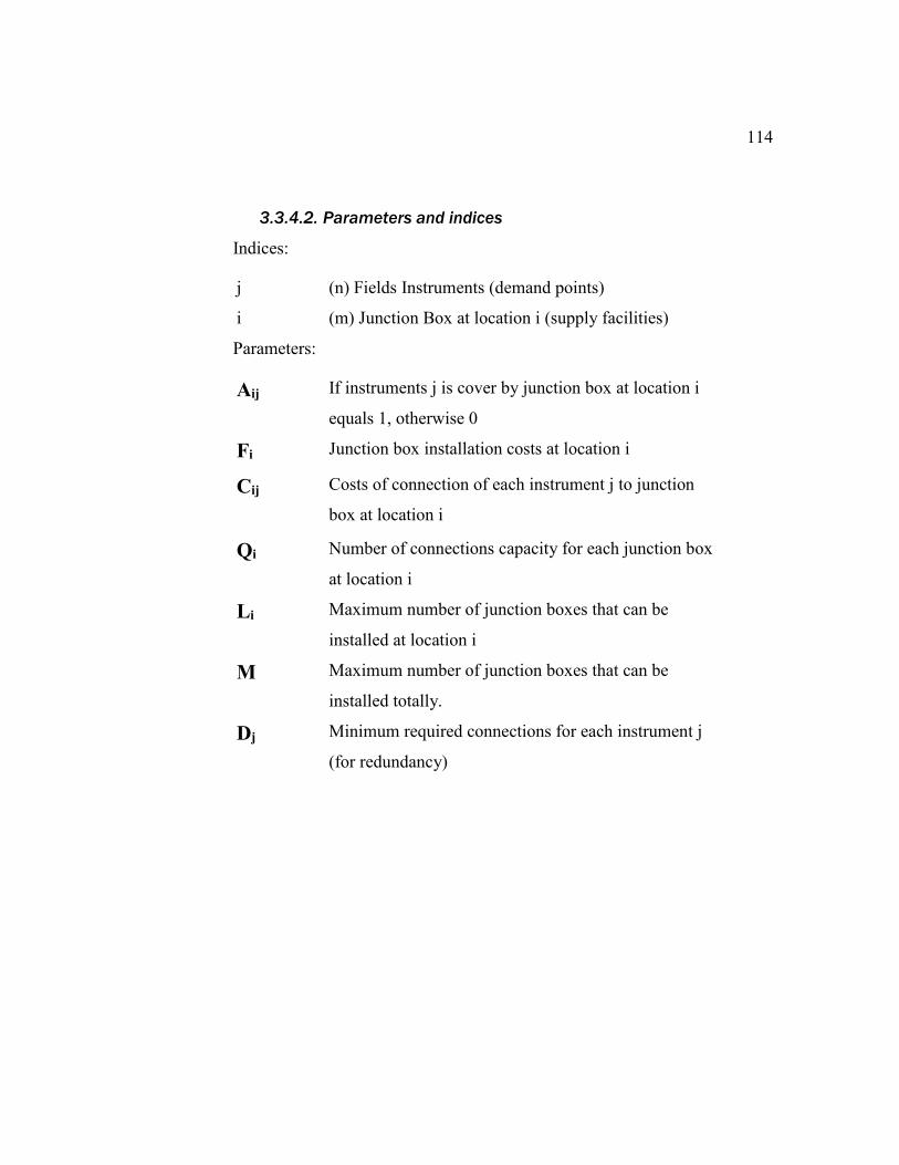
114
3.3.4.2. Parameters and indices
Indices:
j (n) Fields Instruments (demand points)
i (m) Junction Box at location i (supply facilities)
Parameters:
Aij If instruments j is cover by junction box at location i
equals 1, otherwise 0
Fi Junction box installation costs at location i
Cij Costs of connection of each instrument j to junction
box at location i
Qi Number of connections capacity for each junction box
at location i
Li Maximum number of junction boxes that can be
installed at location i
M Maximum number of junction boxes that can be
installed totally.
Dj Minimum required connections for each instrument j
(for redundancy)
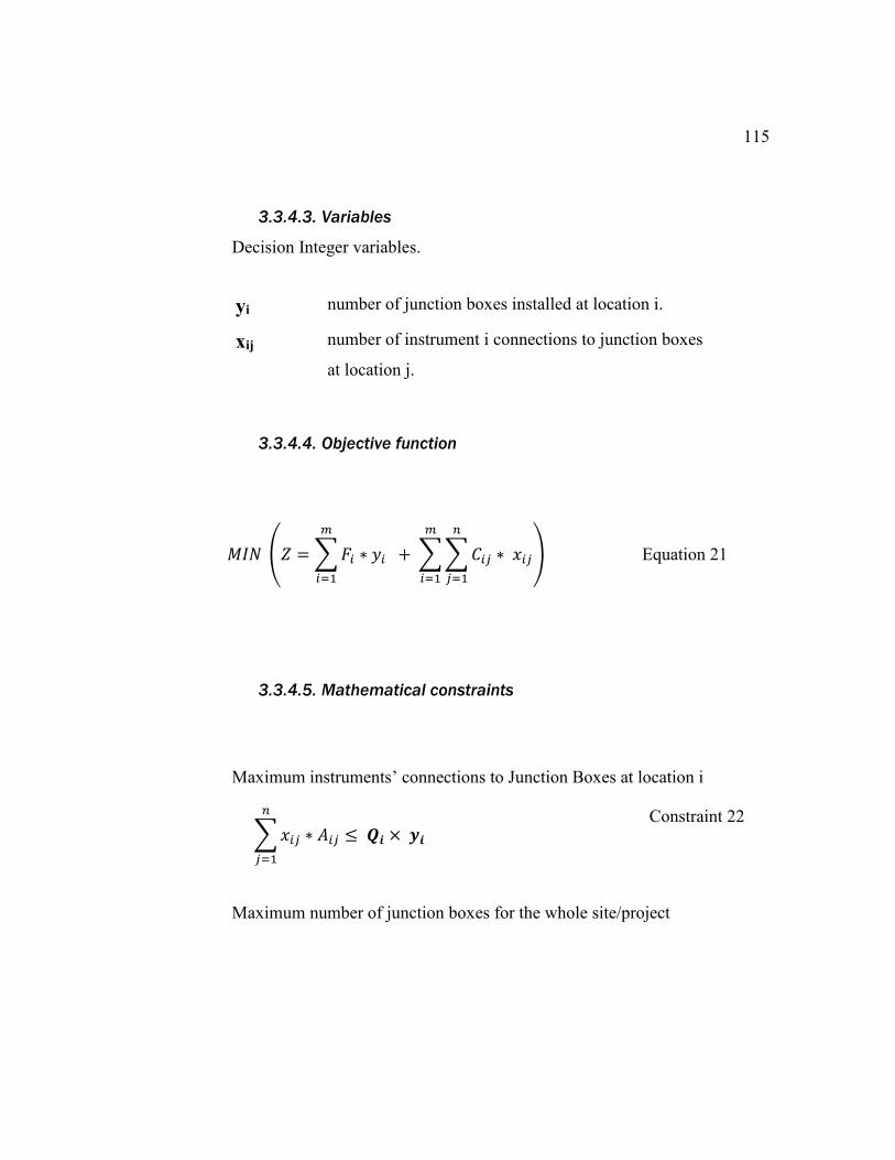
115
3.3.4.3. Variables
Decision Integer variables.
yi number of junction boxes installed at location i.
xij number of instrument i connections to junction boxes
at location j.
3.3.4.4. Objective function
𝑀𝐼𝑁 (𝑍 = ∑ 𝐹𝑖 ∗ 𝑦𝑖
𝑚
𝑖=1
+ ∑ ∑ 𝐶𝑖𝑗 ∗ 𝑥𝑖𝑗
𝑛
𝑗=1
𝑚
𝑖=1
) Equation 21
3.3.4.5. Mathematical constraints
Maximum instruments’ connections to Junction Boxes at location i
∑ 𝑥𝑖𝑗
𝑛
𝑗=1
∗ 𝐴𝑖𝑗 ≤ 𝑸𝒊 × 𝒚𝒊 Constraint 22
Maximum number of junction boxes for the whole site/project
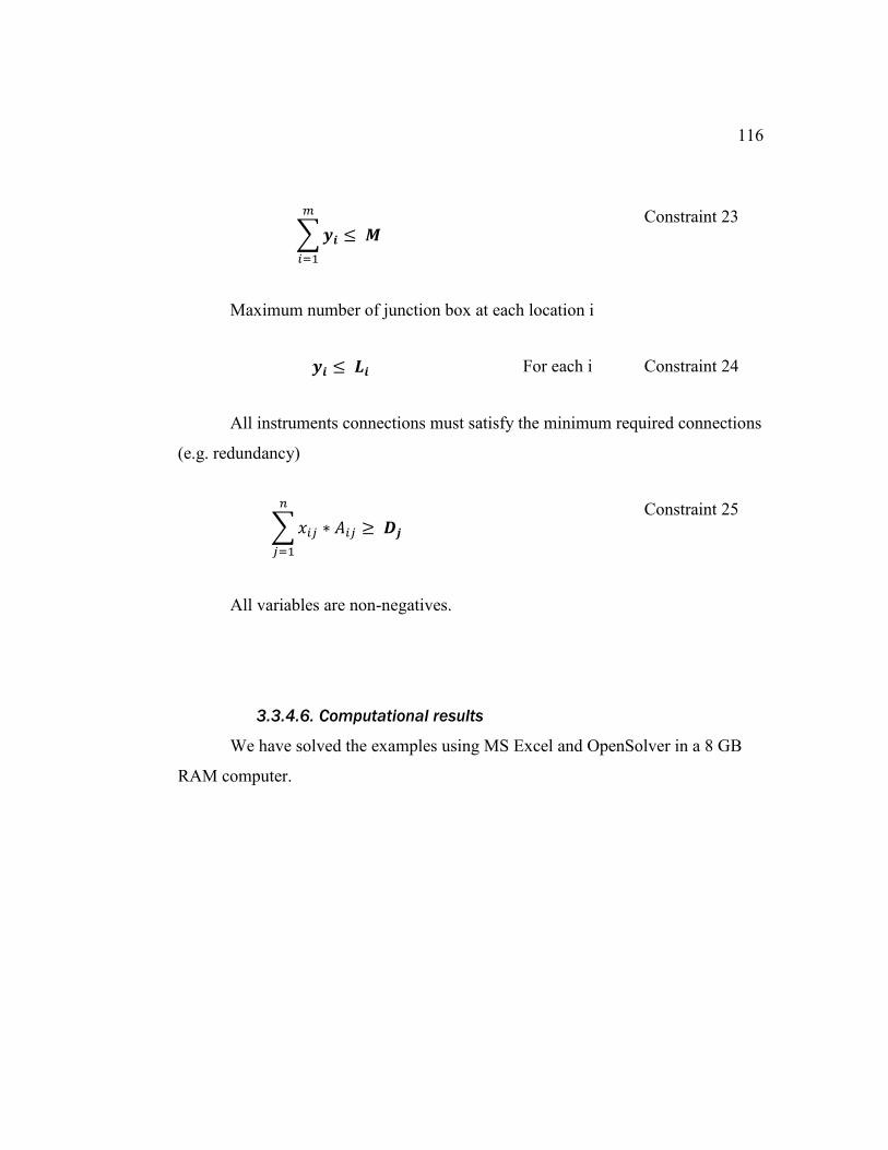
116
∑ 𝒚𝒊
𝑚
𝑖=1
≤ 𝑴 Constraint 23
Maximum number of junction box at each location i
𝒚𝒊 ≤ 𝑳𝒊 For each i Constraint 24
All instruments connections must satisfy the minimum required connections
(e.g. redundancy)
∑ 𝑥𝑖𝑗
𝑛
𝑗=1
∗ 𝐴𝑖𝑗 ≥ 𝑫𝒋 Constraint 25
All variables are non-negatives.
3.3.4.6. Computational results
We have solved the examples using MS Excel and OpenSolver in a 8 GB
RAM computer.
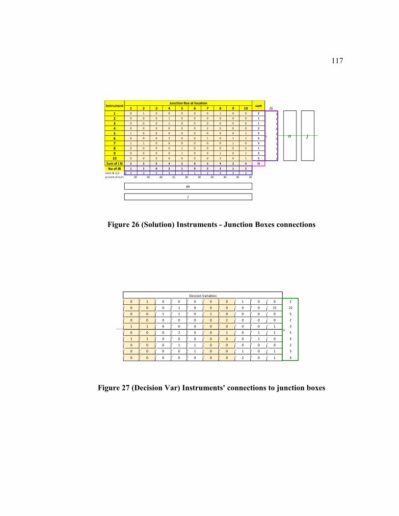
117
Figure 26 (Solution) Instruments - Junction Boxes connections
Figure 27 (Decision Var) Instruments' connections to junction boxes
1 2 3 4 5 6 7 8 9 10 Dj
1 0 1 0 0 0 0 0 1 0 0 2 2
2 0 0 0 1 0 0 0 0 0 0 1 1
3 0 0 0 1 0 0 0 0 0 0 1 1
4 0 0 0 0 0 0 2 0 0 0 2 2
5 1 0 0 0 0 0 0 0 0 1 2 2
6 0 0 0 2 0 0 1 0 1 1 5 5
7 1 1 0 0 0 0 0 0 1 0 3 1
8 0 0 0 0 1 0 0 0 0 0 1 1
9 0 0 0 0 1 0 0 1 0 1 3 1
10 0 0 0 0 0 0 0 2 0 1 3 2
Sum of I Xi 2 2 0 4 2 0 3 4 2 4 21
No of JB 1 1 0 2 1 0 2 2 1 2
limit JB (Li) 3 3 3 3 3 1 2 3 3 2
qi Limit of inst in JB 20 30 40 25 30 30 30 30 30 30
n j
m
i
InstrumentJunction Box at location
sum
min
≤
≥
0 1 0 0 0 0 0 1 0 0 2
0 0 0 1 0 0 0 0 0 21 22
0 0 1 1 0 1 0 0 0 0 3
0 0 0 0 0 0 2 0 0 0 2
1 1 0 0 0 0 0 0 0 1 3
0 0 0 2 0 0 1 0 1 1 5
1 1 0 0 0 0 0 0 1 0 3
0 0 0 1 1 0 0 0 0 0 2
0 0 0 0 1 0 0 1 0 1 3
0 0 0 0 0 0 0 2 0 1 3
Decsion Variables
≤
i i i i i i i i i i
i i i i i i i i i i
i i i i i i i i i i
i i i i i i i i i i
i i i i i i i i i i
i i i i i i i i i i
i i i i i i i i i i
i i i i i i i i i i
i i i i i i i i i i
i i i i i i i i i i
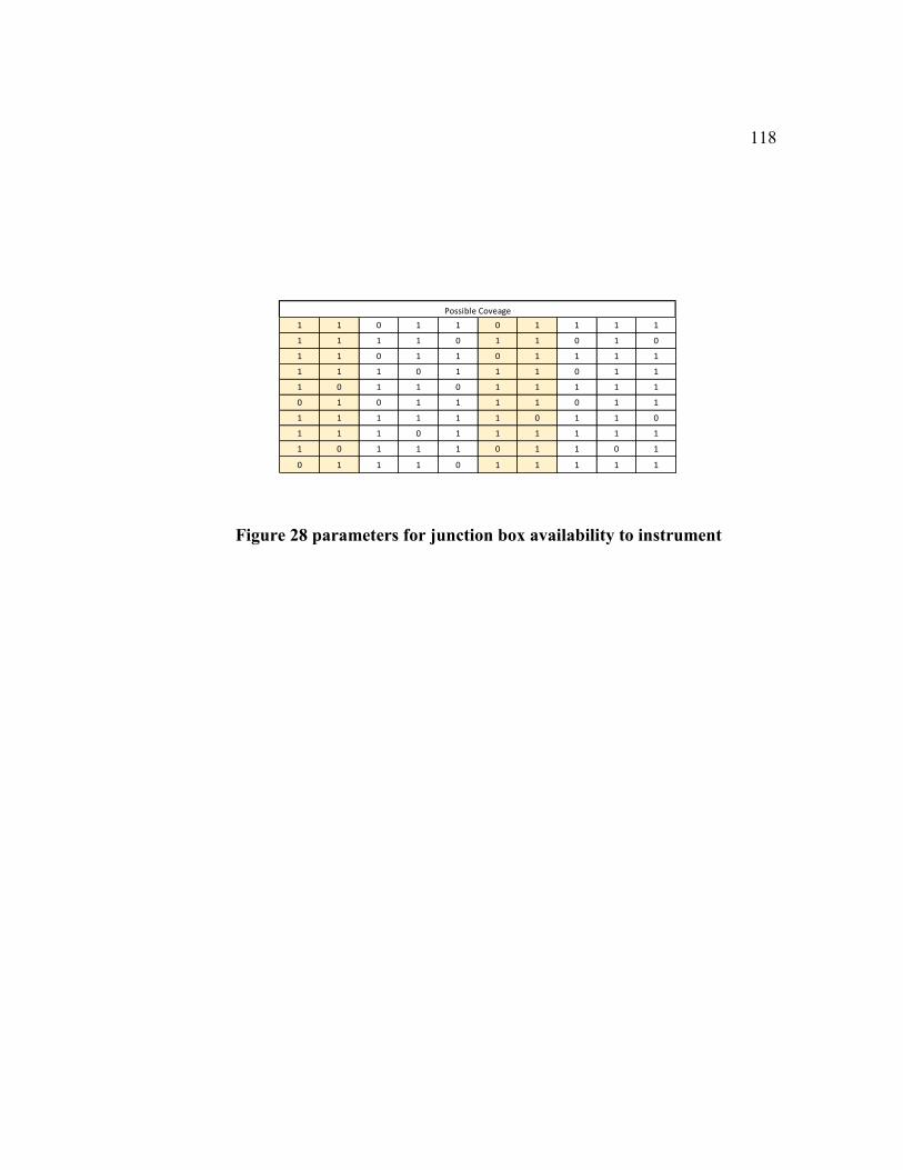
118
Figure 28 parameters for junction box availability to instrument
1 1 0 1 1 0 1 1 1 1
1 1 1 1 0 1 1 0 1 0
1 1 0 1 1 0 1 1 1 1
1 1 1 0 1 1 1 0 1 1
1 0 1 1 0 1 1 1 1 1
0 1 0 1 1 1 1 0 1 1
1 1 1 1 1 1 0 1 1 0
1 1 1 0 1 1 1 1 1 1
1 0 1 1 1 0 1 1 0 1
0 1 1 1 0 1 1 1 1 1
Possible Coveage
119
4. Conclusion
4.1. Summary
This is a Proof-of-concept study which demonstrated that the potential of
facilities layout problem can be greatly realized if approached by system
engineering methodologies. In addition, the volume of recent research on FLP
fields suggests the sustainable need of new solutions and innovative approaches.
4.2. Problems arising during the research
There were several issues we faced when we conducted this research
approach. Since our approach in the literature review were more toward
quantitative, most of the issues were related to the magnitude of the data to be
considered for the revision. Besides, the new system engineering perspective has
its toll as well. Below are the digests of such issues.
4.2.1. Problems during data collection
Large number of research articles have been published in the latest years,
resulting in several surveys papers that capture portion of the published works.
Simple search on one of database journals (e.g. Science Direct) of the layout
problems would results in thousands of articles during the last few years. Some of
the inclusive survey work was published as a thesis on the usage of metaheuristics
approach by FLP (Barsegar).
120
In order to demonstrate very accurate and exact representative trends of the
layout problems in general, as well as their adoption of System Engineering
approach in particular, reviewers will require considerable amount of collaborative
efforts among system engineering researchers.
4.2.2. Problems resulting from the research design
The FLP research area is highly rich in technical approaches and solutions
yet it lacks matured design frameworks. Very few articles, compared to the large
published works, have adopted or at least addressed some of topics related to FLP
design framework.
In addition, pioneering to treat such complex subject, i.e. FLP, using
System Engineering will not easily bring about all the advantages of realizing the
newly FLPSE. Moreover, the functional contexts of FLP will dictate the majority
of System Engineering methodologies appropriate for those specific fields. For
example, in our case studies, safety margins around the equipment are of vital
importance in industrial facilities; hence functional analysis would consider safety
requirements. However, we believe that adopting and applying System
Engineering to FLP through this thesis, will encourage and bring the attention of
other researches to the great outcomes of such framework for FLP.
121
4.3. Recommendations
FLP is complex, large-scale, and resource demanding problems. We
promote for a well-established framework for approaching such type of problems,
especially for industrial applications. In such applications, the depth and breadth of
knowledge, resources, and endeavors mandate collaborative efforts inside
framework. As this reports shows, we are highly recommending System
Engineering approach as a framework.
4.4. Future Research
Dynamic FLP is the new trend on the last few years and it is gaining
momentum. The time elements in such FLP will encourage more perspective for
all the FLP life cycle stages, such as expansions or retirements. Similarly, robust
and resilient FLP are fresh research areas.
On the other hand, we foresee a more adoption and pioneering
implementation of System Engineering to FLP in the industrial sectors due to its
robustness in treating complex systems.

122
References
Generic Bibliography
Arrasmith, W. (2015). Systems Engineering and Analysis of Electro-Optical and Infrared
Systems: CRC Press.
Asef-Vaziri, A., & Laporte, G. (2005). Loop based facility planning and material handling.
European Journal of Operational Research, 164(1), 1–11.
doi:10.1016/j.ejor.2004.01.037
Bahill, A. T., & Gissing, B. (1998). Re-evaluating systems engineering concepts using
systems thinking. IEEE Transactions on Systems, Man and Cybernetics, Part C
(Applications and Reviews), 28(4), 516–527. doi:10.1109/5326.725338
Barsegar, J. A Survey of Metaheuristics for Facility Layout Problems. University of Rhode
Island, United States -- Rhode Island. Retrieved from
http://search.proquest.com.portal.lib.fit.edu/docview/899274005?accountid=27313
Benjaafar, S., Heragu, S. S., & Irani, S. A. (2002). Next Generation Factory Layouts:
Research Challenges and Recent Progress. Interfaces, 32(6), 58–76.
doi:10.1287/inte.32.6.58.6473
Blanchard, B. S., & Fabrycky, W. J. (2011). Systems engineering and analysis.
Johanneshov: MTM.
Con-struct (Author). (2012). Piping and instrumentation diagram of pump with storage
tank. Retrieved from
https://en.wikipedia.org/wiki/File:Pump_with_tank_pid_en.svg
Currie, J., & Wilson, D. I. (2012). OPTI: Lowering the Barrier Between Open Source
Optimizers and the Industrial MATLAB User. In N. Sahinidis & J. Pinto (Eds.),
Foundations of Computer-Aided Process Operations. Savannah, Georgia, USA.
Daniele Pugliesi (Photographer). Functional levels of a Distributed Control System.
Retrieved from
https://en.wikipedia.org/wiki/File:Functional_levels_of_a_Distributed_Control_Sy
stem.svg
Drira, A., Pierreval, H., & Hajri-Gabouj, S. (2007). Facility layout problems: A survey.
Annual Reviews in Control, 31(2), 255–267. doi:10.1016/j.arcontrol.2007.04.001
Dykes, K., Felker, F., Meadows, R., & National Renewable Energy Laboratory. (2011).
Applications of systems engineering to the research, design, and development of
wind energy systems (5000-52616;5000-52616.;). Golden, Colo: National
Renewable Energy Laboratory.
123
Encyclopedia of Algorithms. (2016). New York, NY: Springer New York; Imprint:
Springer.
Fink, A., Voß, S., & Woodruff, D. L. (2003). Metaheuristic Class Libraries. In F. Glover &
G. A. Kochenberger (Eds.), International series in operations research &
management science: Vol. 57. Handbook of Metaheuristics (Vol. 57, pp. 515–535).
Boston: Kluwer Academic Publishers. doi:10.1007/0-306-48056-5_18
Foulds, L. R., & Hamacher, H. W. (2001). Facilities Layout Problems. In C. A. Floudas &
P. M. Pardalos (Eds.), Encyclopedia of Optimization (pp. 975–979). Boston, MA:
Springer US. doi:10.1007/0-306-48332-7_128
Gendreau, M., & Potvin, J.-Y. (2010). Handbook of metaheuristics (2nd ed.). International
series in operations research & management science: Vol. 146. New York:
Springer.
Glover, F., & Sörensen, K. (2015). Metaheuristics. Scholarpedia, 10(4), 6532.
doi:10.4249/scholarpedia.6532
Goldberg, B. E. (1994). System engineering toolbox for design-oriented engineers. NASA
reference publication: Vol. 1358. MSFC, Ala.: National Aeronautics and Space
Administration, Marshall Space Flight Center.
Hekmatfar, M., & Zanjirani Farahani, R. (2009). Facility location: Concepts, models,
algorithms and case studies. Contributions to management science. Heidelberg,
London: Physica; Springer [distributor].
Jain, A. K., Khare, V. K., & Mishra, P. M. (2013). Facility planning and associated
problems: A Survey. Innovative Systems Design and Engineering, 4(6), 1–8.
Keller, B., & Buscher, U. (2015). Single row layout models. European Journal of
Operational Research, 245(3), 629–644. doi:10.1016/j.ejor.2015.03.016
Kjell B. Zandin. (2001). FACILITIES LAYOUT AND DESIGN. In Maynard’s Industrial
Engineering Handbook, Fifth Edition (5th ed.). McGraw Hill Professional, Access
Engineering. Retrieved from
https://accessengineeringlibrary.com/browse/maynards-industrial-engineering-
handbook-fifth-edition/p2000a1fc9978.21001
KumarBhati, R., & Rasool, A. (2014). Quadratic Assignment Problem and its Relevance to
the Real World: A Survey. International Journal of Computer Applications, 96(9),
42–47. doi:10.5120/16825-6584
Liggett, R. S. (2000). Automated facilities layout: Past, present and future. Automation in
Construction, 9(2), 197–215. doi:10.1016/S0926-5805(99)00005-9
Lin, L. C., & Sharp, G. P. (1999). Application of the integrated framework for the plant
layout evaluation problem. European Journal of Operational Research, 116(1),
118–138. doi:10.1016/S0377-2217(98)00174-X
Loiola, E. M., de Abreu, Nair Maria Maia, Boaventura-Netto, P. O., Hahn, P., & Querido,
T. (2007). A survey for the quadratic assignment problem. European Journal of
Operational Research, 176(2), 657–690. doi:10.1016/j.ejor.2005.09.032
Luke, S. (2013). Essentials of Metaheuristics (second): Lulu. Retrieved from
http://cs.gmu.edu/~sean/book/metaheuristics/
124
Material Handling Industry. (2016). Glossary. Retrieved from http://www.mhi.org/glossary
Mbeychok (Editor). (2007). A schematic flow diagram of a typical oil refinery. Retrieved
from https://en.wikipedia.org/wiki/File:RefineryFlow.png
Moatari-Kazerouni, A., Chinniah, Y., & Agard, B. (2014). Integrating occupational health
and safety in facility layout planning, part I: Methodology. International Journal of
Production Research, 53(11), 3243–3259. doi:10.1080/00207543.2014.970712
Moslemipour, G., Lee, T. S., & Rilling, D. (2012). A review of intelligent approaches for
designing dynamic and robust layouts in flexible manufacturing systems. The
International Journal of Advanced Manufacturing Technology, 60(1-4), 11–27.
doi:10.1007/s00170-011-3614-x
Raman, D., Nagalingam, S. V., & Lin, G. C. (2009). Towards measuring the effectiveness
of a facilities layout. Robotics and Computer-Integrated Manufacturing, 25(1),
191–203. doi:10.1016/j.rcim.2007.06.003
Saravanan, M., & Ganesh Kumar, S. (2013). Different approaches for the loop layout
problems: A review. The International Journal of Advanced Manufacturing
Technology, 69(9-12), 2513–2529. doi:10.1007/s00170-013-5133-4
Secl (Photographer). (2006). Petrochemical Plant. Retrieved from
https://en.wikipedia.org/wiki/File:TASNEE_001.jpg
Singh, S. P., & Sharma, R. R. K. (2006). A review of different approaches to the facility
layout problems. The International Journal of Advanced Manufacturing
Technology, 30(5-6), 425–433. doi:10.1007/s00170-005-0087-9
Skiena, S. S. (2008). The algorithm design manual (2nd ed.). London: Springer.
Systems Engineering Approach. (2012). In M. H. Sadraey (Ed.), Aircraft Design (pp. 19–
48). Chichester, UK: John Wiley & Sons, Ltd. doi:10.1002/9781118352700.ch2
Tao, J., Wang, P., Qiao, H., & Tang, Z. (2012). Facility layouts based on intelligent
optimization approaches. In 2012 IEEE Fifth International Conference on
Advanced Computational Intelligence (ICACI) (pp. 502–508).
doi:10.1109/ICACI.2012.6463215
Tiusanen, R. (2015). Systems Engineering Approach to Risk Assessment of Automated
Mobile Work Machine Applications. In P. W. Tse, J. Mathew, K. Wong, R. Lam,
& C. Ko (Eds.), Lecture Notes in Mechanical Engineering. Engineering Asset
Management - Systems, Professional Practices and Certification (pp. 1763–1774).
Cham: Springer International Publishing. doi:10.1007/978-3-319-09507-3_151
Tompkins, J. A. (2010). Facilities planning (4th ed.). Hoboken, NJ, Chichester: John Wiley
& Sons; John Wiley [distributor].
United States. (2007). NASA Systems Engineering Handbook. Washington D.C.: National
Aeronautics and Space Administration.
Voß, S. (2001). Metaheuristics. In C. A. Floudas & P. M. Pardalos (Eds.), Encyclopedia of
Optimization (pp. 2061–2075). Boston, MA: Springer US. doi:10.1007/978-0-387-
74759-0_367

125
Walden, D. D., Roedler, G. J., Forsberg, K., Hamelin, R. D., & Shortell, T. M. (2015).
Systems engineering handbook: A guide for system life cycle processes and
activities (4th edition). Hoboken, New Jersey: Wiley.
Yang, T., & Hung, C.-C. (2007). Multiple-attribute decision making methods for plant
layout design problem. Robotics and Computer-Integrated Manufacturing, 23(1),
126–137. doi:10.1016/j.rcim.2005.12.002
Yasseri, S. (2014). Application of systems engineering to subsea development. Underwater
Technology, 32(2), 93–109. doi:10.3723/ut.32.093

126
FLP Published Articles Bibliography
A. Chraibi, S. Kharraja, I. H. Osman, & O. Elbeqqali (2013). A mixed integer
programming formulation for solving operating theatre layout problem: A multi-
goal approach. In Industrial Engineering and Systems Management (IESM),
Proceedings of 2013 International Conference on (pp. 1–10).
Amaral, A. R. S. (2008). An Exact Approach to the One-Dimensional Facility Layout
Problem. Operations research, 56(4), 1026–1033. doi:10.1287/opre.1080.0548
Amit, N., Suhadak, N., Johari, N., & Kassim, I. (2012). Using simulation to solve facility
layout for food industry at XYZ Company. In 2012 IEEE Symposium on
Humanities, Science and Engineering Research (SHUSER) (pp. 647–652).
doi:10.1109/SHUSER.2012.6268900
Anjos, M. F., & Vannelli, A. (2006). A New Mathematical-Programming Framework for
Facility-Layout Design. INFORMS Journal on Computing, 18(1), 111–118.
doi:10.1287/ijoc.1040.0103
Anjos, M. F., & Vannelli, A. (2008). Computing Globally Optimal Solutions for Single-
Row Layout Problems Using Semidefinite Programming and Cutting Planes.
INFORMS Journal on Computing, 20(4), 611–617. doi:10.1287/ijoc.1080.0270
Assem, M., Ouda, B. K., & Wahed, M. A. (2012). Improving operating theatre design
using facilities layout planning. In 2012 Cairo International Biomedical
Engineering Conference (CIBEC) (pp. 109–113).
doi:10.1109/CIBEC.2012.6473314
Azadeh, A., Moghaddam, M., Nazari, T., & Sheikhalishahi, M. (2016). Optimization of
facility layout design with ambiguity by an efficient fuzzy multivariate approach.
The International Journal of Advanced Manufacturing Technology, 84(1-4), 565–
579. doi:10.1007/s00170-015-7714-x
Azadivar, F., & Wang, J. (2010). Facility layout optimization using simulation and genetic
algorithms. International Journal of Production Research, 38(17), 4369–4383.
doi:10.1080/00207540050205154
B. Xing, W. J. Gao, F. V. Nelwamondo, K. Battle, & T. Marwala (2010). Swarm
intelligence in cellular manufacturing: application of hybrid ant system to
manufacturing cell machine layout problem. In World Automation Congress
(WAC), 2010 (pp. 1–6).
BALAKRISHNAN, J., & HUNGCHENG, C. (2009). The dynamic plant layout problem:
Incorporating rolling horizons and forecast uncertainty☆. Omega, 37(1), 165–177.
doi:10.1016/j.omega.2006.11.005
Barbosa-Póvoa, A. P., Mateus, R., & Novais, A. Q. (2002). Optimal Design and Layout of
Industrial Facilities: A Simultaneous Approach. Industrial & Engineering
Chemistry Research, 41(15), 3601–3609. doi:10.1021/ie010660s
127
Barbosa-Póvoa, A. P., Mateus, R., & Novais, A. Q. (2002). Optimal Design and Layout of
Industrial Facilities: An Application to Multipurpose Batch Plants. Industrial &
Engineering Chemistry Research, 41(15), 3610–3620. doi:10.1021/ie010661k
Bing, C., Shaowei, W., Shan, L., & Gang, W. (2009). Digital Workshop Layout Evaluation
and Adjustment Based on the Fuzzy-AHP and Generic Algorithm. In 2009
International Conference on Computational Intelligence and Natural Computing
(CINC) (pp. 437–440). doi:10.1109/CINC.2009.165
Bozer, Y. A., Meller, R. D., & Erlebacher, S. J. (1994). An Improvement-Type Layout
Algorithm for Single and Multiple-Floor Facilities. Management Science, 40(7),
918–932. doi:10.1287/mnsc.40.7.918
Bozer, Y. A., Meller, R. D., & (None). (1997). A reexamination of the distance-based
facility layout problem. IIE Transactions, 29(7), 549.
doi:10.1080/07408179708966365
Bozorgi, N., Abedzadeh, M., & Zeinali, M. (2015). Tabu search heuristic for efficiency of
dynamic facility layout problem. The International Journal of Advanced
Manufacturing Technology, 77(1-4), 689–703. doi:10.1007/s00170-014-6460-9
Chang, C.-C., Wu, T.-H., & Chung, S.-H. (2009). A Novel Approach for Cell Formation
and Cell Layout Design in Cellular Manufacturing System. In 2009 International
Conference on Management and Service Science (MASS) (pp. 1–4).
doi:10.1109/ICMSS.2009.5304612
Chen, G., & Rogers, J. (2009). Managing dynamic facility layout with multiple objectives.
In Technology (pp. 1175–1184). doi:10.1109/PICMET.2009.5262013
Chen, G. Y., & Rogers, K. J. (2009). Proposition of two multiple criteria models applied to
Dynamic Multi-objective Facility Layout Problem based on Ant Colony
Optimization. In 2009 IEEE International Conference on Industrial Engineering
and Engineering Management (IEEM) (pp. 1553–1557).
doi:10.1109/IEEM.2009.5373095
Chen, K., Song, M. X., Zhang, X., & Wang, S. F. (2016). Wind turbine layout optimization
with multiple hub height wind turbines using greedy algorithm. Renewable
Energy, 96, 676–686. doi:10.1016/j.renene.2016.05.018
Chen, Q., & Sun, T. (2015). A model for the layout of bike stations in public bike-sharing
systems. Journal of Advanced Transportation, 49(8), 884–900.
doi:10.1002/atr.1311
Choi, M., Kim, S. H., & Chung, H. (2016). Optimal shipyard facility layout planning based
on a genetic algorithm and stochastic growth algorithm. Ships and Offshore
Structures, 1–9. doi:10.1080/17445302.2016.1176294
Chraibi, A., Kharraja, S., Osman, I. H., & Elbeqqali, O. (2015). Multi-Agent System for
solving Dynamic Operating Theater Facility Layout Problem. IFAC-
PapersOnLine, 48(3), 1146–1151. doi:10.1016/j.ifacol.2015.06.238
Chraibi, A., Kharraja, S., Osman, I. H., & Elbeqqali, O. (2015). Optimization of dynamic
operating theatre facility layout. In 2015 International Conference on Industrial
128
Engineering and Systems Management (IESM) (pp. 262–271).
doi:10.1109/IESM.2015.7380169
Chung, J., & Tanchoco, J. (2010). The double row layout problem. International Journal of
Production Research, 48(3), 709–727. doi:10.1080/00207540802192126
Chung, J., & Tanchoco, J. (2010). Layout design with hexagonal floor plans and material
flow patterns. International Journal of Production Research, 48(12), 3407–3428.
doi:10.1080/00207540902810510
Corry, P., & Kozan, E. (2004). Ant Colony Optimisation for Machine Layout Problems.
Computational Optimization and Applications, 28(3), 287–310.
doi:10.1023/B:COAP.0000033965.99769.98
Derakhshan Asl, A., Wong, K. Y., & Tiwari, M. K. (2015). Unequal-area stochastic
facility layout problems: Solutions using improved covariance matrix adaptation
evolution strategy, particle swarm optimisation, and genetic algorithm.
International Journal of Production Research, 54(3), 799–823.
doi:10.1080/00207543.2015.1070217
Díaz-Ovalle, C., Vázquez-Román, R., & Sam Mannan, M. (2010). An approach to solve
the facility layout problem based on the worst-case scenario. Journal of Loss
Prevention in the Process Industries, 23(3), 385–392.
doi:10.1016/j.jlp.2010.01.004
Dong, M., Wu, C., & Hou, F. (2009). Shortest path based simulated annealing algorithm
for dynamic facility layout problem under dynamic business environment. Expert
Systems with Applications, 36(8), 11221–11232. doi:10.1016/j.eswa.2009.02.091
Drira, A., Pierreval, H., & Hajri-Gabouj, S. (2013). Design of a robust layout with
information uncertainty increasing over time: A fuzzy evolutionaryapproach.
Engineering Applications of Artificial Intelligence, 26(3), 1052–1060.
doi:10.1016/j.engappai.2012.12.007
Eklund, N., Embrechts, M. J., & Goetschalckx, M. (2006). Efficient chromosome encoding
and problem-specific mutation methods for the flexible bay facility layout
problem. IEEE Transactions on Systems, Man and Cybernetics, Part C
(Applications and Reviews), 36(4), 495–502. doi:10.1109/TSMCC.2006.875412
Garci, L., Pierreval, H., Salas-Morera, L., & Arauzo-Azofra, A. (2010). An Interactive
Genetic Algorithm with c-Means clustering for the Unequal Area Facility Layout
Problem. In 2010 10th International Conference on Intelligent Systems Design and
Applications (ISDA) (pp. 61–66). doi:10.1109/ISDA.2010.5687291
García-Hernández, L., Arauzo-Azofra, A., Salas-Morera, L., Pierreval, H., & Corchado, E.
(2015). Facility layout design using a multi-objective interactive genetic algorithm
to support the DM. Expert Systems, 32(1), 94–107. doi:10.1111/exsy.12064
Guirardello, R., & Swaney, R. E. (2005). Optimization of process plant layout with pipe
routing. Computers & Chemical Engineering, 30(1), 99–114.
doi:10.1016/j.compchemeng.2005.08.009
Guoxin Wang, Yan Yan, Xiang Zhang, Jingchang Shangguan, & Yanqiu Xiao (2008). A
simulation optimization approach for facility layout problem. In 2008 IEEE
129
International Conference on Industrial Engineering and Engineering Management
(IEEM) (pp. 734–738). doi:10.1109/IEEM.2008.4737966
Hahn, P., MacGregor Smith, J., & Zhu, Y.-R. (2010). The Multi-Story Space Assignment
Problem. Annals of Operations Research, 179(1), 77–103. doi:10.1007/s10479-
008-0474-3
Hamedi, M., & Esmaeilian, G. (2015). Functional and distributed layouts and their
effectiveness on capability-based Virtual Cellular Manufacturing systems
performance. In 2015 International Conference on Industrial Engineering and
Operations Management (IEOM) (pp. 1–8). doi:10.1109/IEOM.2015.7093847
Han, K., Kim, Y. H., Jang, N., Kim, H., Shin, D., & Yoon, E. S. (2013). Risk Index
Approach for the Optimal Layout of Chemical Processes Minimizing Risk to
Humans. Industrial & Engineering Chemistry Research, 52(22), 7274–7281.
doi:10.1021/ie3025104
HASSAN, M. M. D. (1994). Machine layout problem in modern manufacturing facilities.
International Journal of Production Research, 32(11), 2559–2584.
doi:10.1080/00207549408957084
HASSAN, M. M. D., & HOGG, G. L. (1991). On constructing a block layout by graph
theory. International Journal of Production Research, 29(6), 1263–1278.
doi:10.1080/00207549108930132
Heragu, S., & Kusiak, A. (1988). Machine Layout Problem In Flexible Manufacturing
Systems. Operations research, 36(2), 258–268. doi:10.1287/opre.36.2.258
Hifi, M., & M'Hallah, R. (2003). A hybrid algorithm for the two-dimensional layout
problem: The cases of regular and irregular shapes. International Transactions in
Operational Research, 10(3), 195–216. doi:10.1111/1475-3995.00404
Ho, Y.-C., & Moodie, C. L. (1998). Machine layout with a linear single-row flow path in
an automated manufacturing system. Journal of Manufacturing Systems, 17(1), 1–
22. doi:10.1016/S0278-6125(98)80006-X
Hosseini-Nasab, H., & Emami, L. (2013). A hybrid particle swarm optimisation for
dynamic facility layout problem. International Journal of Production Research,
51(14), 4325–4335. doi:10.1080/00207543.2013.774486
Hui, L., & Shi-you, Q. (2013). Systematic layout planning: A study on coal mine facilities.
In 2013 International Conference on Management Science and Engineering
(ICMSE) (pp. 1944–1949). doi:10.1109/ICMSE.2013.6586530
Izadinia, N., & Eshghi, K. (2016). A robust mathematical model and ACO solution for
multi-floor discrete layout problem with uncertain locations and demands.
Computers & Industrial Engineering, 96, 237–248. doi:10.1016/j.cie.2016.02.026
Izadinia, N., Eshghi, K., & Salmani, M. H. (2014). A robust model for multi-floor layout
problem. Computers & Industrial Engineering, 78, 127–134.
doi:10.1016/j.cie.2014.09.023
J. Y. Qi (2010). Application of improved simulated annealing algorithm in facility layout
design. In Proceedings of the 29th Chinese Control Conference (pp. 5224–5227).
130
Jung, S., Ng, D., Diaz-Ovalle, C., Vazquez-Roman, R., & Mannan, M. S. (2011). New
Approach To Optimizing the Facility Siting and Layout for Fire and Explosion
Scenarios. Industrial & Engineering Chemistry Research, 50(7), 3928–3937.
doi:10.1021/ie101367g
Juu-Hwa Ting, & Tanchoco, J. (2001). Optimal bidirectional spine layout for overhead
material handling systems. IEEE Transactions on Semiconductor Manufacturing,
14(1), 57–64. doi:10.1109/66.909655
Kaku, B. K., & Mazzola, J. B. (1997). A Tabu-Search Heuristic for the Dynamic Plant
Layout Problem. INFORMS Journal on Computing, 9(4), 374–384.
doi:10.1287/ijoc.9.4.374
Kanduc, T., & Rodic, B. (2015). Optimisation of factory floor layout using force-directed
graph drawing algorithm. In 2015 38th International Convention on Information
and Communication Technology, Electronics and Microelectronics (MIPRO) (pp.
1087–1092). doi:10.1109/MIPRO.2015.7160437
Kheirkhah, A., Navidi, H., & Messi Bidgoli, M. (2015). Dynamic Facility Layout Problem:
A New Bilevel Formulation and Some Metaheuristic Solution Methods. IEEE
Transactions on Engineering Management, 62(3), 396–410.
doi:10.1109/TEM.2015.2437195
Kia, R., Shirazi, H., Javadian, N., & Tavakkoli-Moghaddam, R. (2014). Designing group
layout of unequal-area facilities in a dynamic cellular manufacturing system with
variability in number and shape of cells. International Journal of Production
Research, 53(11), 3390–3418. doi:10.1080/00207543.2014.986295
Kia, R., Tavakkoli-Moghaddam, R., Javadian, N., Baboli, A., & Kazemi, M. (2011). A
group layout design model of a dynamic cellular manufacturing system. In 2011
IEEE 3rd International Conference on Communication Software and Networks
(ICCSN) (pp. 745–749). doi:10.1109/ICCSN.2011.6014998
Kia, R., Tavakkoli-Moghaddam, R., Javadian, N., Kazemi, M., & Khorrami, J. (2011). A
simulated annealing for solving a group layout design model of a dynamic cellular
manufacturing system. In 2011 IEEE International Conference on Industrial
Engineering and Engineering Management (IEEM) (pp. 1113–1117).
doi:10.1109/IEEM.2011.6118088
Kim, S., Chung, H., & Kim, M. (2014). Optimization of P.E. area division and
arrangement based on product mix. Journal of Marine Science and Technology,
19(4), 351–359. doi:10.1007/s00773-014-0274-1
Kim, J.-Y., & Kim, Y.-D. (1995). Graph theoretic heuristics for unequal-sized facility
layout problems. Omega, 23(4), 391–401. doi:10.1016/0305-0483(95)00016-H
KIM, K. H., & TANCHOCO, J. M. A. (1993). Economical design of material flow paths.
International Journal of Production Research, 31(6), 1387–1407.
doi:10.1080/00207549308956797
Komarudin, & Wong, K. Y. (2010). Applying Ant System for solving Unequal Area
Facility Layout Problems. European Journal of Operational Research, 202(3), 730–
746. doi:10.1016/j.ejor.2009.06.016
131
Kouvelis, P., & Kim, M. W. (1992). Unidirectional Loop Network Layout Problem in
Automated Manufacturing Systems. Operations research, 40(3), 533–550.
doi:10.1287/opre.40.3.533
Kulkarni, P. C., & Shanker, K. (2007). A genetic algorithm for layout problems in cellular
manufacturing systems. In 2007 IEEE International Conference on Industrial
Engineering and Engineering Management (pp. 694–698).
doi:10.1109/IEEM.2007.4419279
Kulkarni, P. C., & Shanker, K. (2013). Genetic algorithm approach for solving intercellular
layout problems in cellular manufacturing systems. In 2013 IEEE International
Conference on Industrial Engineering and Engineering Management (IEEM) (pp.
1587–1591). doi:10.1109/IEEM.2013.6962677
Kulturel-Konak, S., & Konak, A. (2014). A large-scale hybrid simulated annealing
algorithm for cyclic facility layout problems. Engineering Optimization, 47(7),
963–978. doi:10.1080/0305215X.2014.933825
Li-fang, W., Fan-Sen, K., Jing-hua, C., & Jian-sha, L. (2012). A new optimization scheme
based logistics cost for plant facility layout. In (pp. 1–4). IEEE.
Liu, X., Wang, S., Huo, Z., Li, F., & Hao, X. (2015). Optimizing layout of pumping well in
irrigation district for groundwater sustainable use in northwest China. Hydrological
Processes, 29(19), 4188–4198. doi:10.1002/hyp.10471
Lu, T., & Srivastava, A. (2015). Modeling and Layout Optimization for Tapered TSVs.
IEEE Transactions on Very Large Scale Integration (VLSI) Systems, 23(12),
3129–3132. doi:10.1109/TVLSI.2014.2384042
Madhusudanan Pillai, V., Hunagund, I. B., & Krishnan, K. K. (2011). Design of robust
layout for Dynamic Plant Layout Problems. Computers & Industrial Engineering,
61(3), 813–823. doi:10.1016/j.cie.2011.05.014
Mahdavi, I., Khaksar-Haghani, F., Javadian, N., & Kia, R. (2011). Multi-floor layout
design of cellular manufacturing systems. In 2011 IEEE 3rd International
Conference on Communication Software and Networks (ICCSN) (pp. 740–744).
doi:10.1109/ICCSN.2011.6014997
Manita, G., Chaieb, I., & Korbaa, O. (2015). A new approach for loop machine layout
problem integrating proximity constraints. International Journal of Production
Research, 54(3), 778–798. doi:10.1080/00207543.2015.1064178
Martinez-Gomez, J., Nápoles-Rivera, F., Ponce-Ortega, J. M., Serna-González, M., & El-
Halwagi, M. M. (2014). Siting Optimization of Facility and Unit Relocation with
the Simultaneous Consideration of Economic and Safety Issues. Industrial &
Engineering Chemistry Research, 53(10), 3950–3958. doi:10.1021/ie402242u
MAYER, B., IRANI, S., & ADRA, H. (2008). Virtual Shop Clusters: A New Layout
Concept for a Ship Repair and Maintenance Facility. Naval Engineers Journal,
120(2), 99–111. doi:10.1111/j.1559-3584.2008.00128.x
McKendall, A. R., & Hakobyan, A. (2010). Heuristics for the dynamic facility layout
problem with unequal-area departments. European Journal of Operational
Research, 201(1), 171–182. doi:10.1016/j.ejor.2009.02.028
132
McKendall, A. R., & Liu, W.-H. (2012). New Tabu search heuristics for the dynamic
facility layout problem. International Journal of Production Research, 50(3), 867–
878. doi:10.1080/00207543.2010.545446
Meller, R. D., Narayanan, V., & Vance, P. H. (1998). Optimal facility layout design.
Operations Research Letters, 23(3-5), 117–127. doi:10.1016/S0167-
6377(98)00024-8
M'Hallah, R., & Bouziri, A. (2016). Heuristics for the combined cut order planning two-
dimensional layout problem in the apparel industry. International Transactions in
Operational Research, 23(1-2), 321–353. doi:10.1111/itor.12104
Michalek, J., & Papalambros, P. (2002). Interactive design optimization of architectural
layouts. Engineering Optimization, 34(5), 485–501. doi:10.1080/03052150214021
Mohan, T. V. K., & Pillai, V. M. (2013). Detailed Dynamic Layout Planning: An Adaptive
Layout Approach. IFAC Proceedings Volumes, 46(9), 2027–2032.
doi:10.3182/20130619-3-RU-3018.00556
Neghabi, H., Eshghi, K., & Salmani, M. H. (2014). A new model for robust facility layout
problem. Information Sciences, 278, 498–509. doi:10.1016/j.ins.2014.03.067
Papageorgiou, L. G., & Rotstein, G. E. (1998). Continuous-Domain Mathematical Models
for Optimal Process Plant Layout. Industrial & Engineering Chemistry Research,
37(9), 3631–3639. doi:10.1021/ie980146v
Park, K., Koo, J., Shin, D., Lee, C. J., & Yoon, E. S. (2011). Optimal multi-floor plant
layout with consideration of safety distance based on mathematical programming
and modified consequence analysis. Korean Journal of Chemical Engineering,
28(4), 1009–1018. doi:10.1007/s11814-010-0470-6
Patsiatzis, D. I., & Papageorgiou, L. G. (2003). Efficient Solution Approaches for the
Multifloor Process Plant Layout Problem. Industrial & Engineering Chemistry
Research, 42(4), 811–824. doi:10.1021/ie020586t
Prasad, N. H., Rajyalakshmi, G., & Reddy, A. S. (2014). A Typical Manufacturing Plant
Layout Design Using CRAFT Algorithm. Procedia Engineering, 97, 1808–1814.
doi:10.1016/j.proeng.2014.12.334
S. Ohmori, K. Yoshimoto, & K. Ogawa (2010). Solving Facility Layout Problem -
continuous simulated annealing-. In Supply Chain Management and Information
Systems (SCMIS), 2010 8th International Conference on (pp. 1–5).
Şahin, R., & Txrkbey, O. (2009). A new hybrid tabu-simulated annealing heuristic for the
dynamic facility layout problem. International Journal of Production Research,
47(24), 6855–6873. doi:10.1080/00207540802376323
Sherali, H. D., Fraticelli, B. M. P., & Meller, R. D. (2003). Enhanced Model Formulations
for Optimal Facility Layout. Operations research, 51(4), 629–644.
doi:10.1287/opre.51.4.629.16096
Singh, S. P., & Singh, V. K. (2010). An improved heuristic approach for multi-objective
facility layout problem. International Journal of Production Research, 48(4), 1171–
1194. doi:10.1080/00207540802534731
133
TAM, K. Y. (1992). A simulated annealing algorithm for allocating space to
manufacturing cells. International Journal of Production Research, 30(1), 63–87.
doi:10.1080/00207549208942878
Tang, L., Zuo, X., Wang, C., & Zhao, X. (2015). A MOEA/D based approach for solving
robust double row layout problem. In 2015 IEEE Congress on Evolutionary
Computation (CEC) (pp. 1966–1973). doi:10.1109/CEC.2015.7257126
Tarkesh, H., Atighehchian, A., & Nookabadi, A. S. (2009). Facility layout design using
virtual multi-agent system. Journal of Intelligent Manufacturing, 20(4), 347–357.
doi:10.1007/s10845-008-0109-1
Tate, D. M., & Smith, A. E. (1995). A genetic approach to the quadratic assignment
problem. Computers & Operations Research, 22(1), 73–83. doi:10.1016/0305-
0548(93)E0020-T
Tavakkoli Moghaddam, R., & Panahi, H. (2007). Solving a new mathematical model of a
closed-loop layout problem with unequal-sized facilities by a genetic algorithm. In
2007 IEEE International Conference on Industrial Engineering and Engineering
Management (pp. 327–331). doi:10.1109/IEEM.2007.4419205
Teo, Y. T., & Ponnambalam, S. G. (2008). A hybrid ACO/PSO heuristic to solve single
row layout problem. In 2008 IEEE International Conference on Automation
Science and Engineering (CASE 2008) (pp. 597–602).
doi:10.1109/COASE.2008.4626491
TRETHEWAY, S. J., & FOOTE, B. L. (1994). Automatic computation and drawing of
facility layouts with logical aisle structures. International Journal of Production
Research, 32(7), 1545–1555. doi:10.1080/00207549408957021
Tu, J.-C., & Chiu, P.-L. (2015). Fuzzy AHP and fuzzy TOPSIS integrated multicriteria
decision-making scheme employing Chinese environmental esthetics for facility
layout design evaluation. Journal of Industrial and Production Engineering, 32(8),
473–485. doi:10.1080/21681015.2015.1072852
Ulutas, B., & Islier, A. A. (2015). Dynamic facility layout problem in footwear industry.
Journal of Manufacturing Systems, 36, 55–61. doi:10.1016/j.jmsy.2015.03.004
Vázquez-Román, R., Lee, J.-H., Jung, S., & Mannan, M. S. (2010). Optimal facility layout
under toxic release in process facilities: A stochastic approach. Computers &
Chemical Engineering, 34(1), 122–133. doi:10.1016/j.compchemeng.2009.08.001
Wang, S., Zuo, X., Liu, X., Zhao, X., & Li, J. (2015). Solving dynamic double row layout
problem via combining simulated annealing and mathematical programming.
Applied Soft Computing, 37, 303–310. doi:10.1016/j.asoc.2015.08.023
Wu, L., Xiao, W., Wang, J., Zhou, H., & Tian, X. (2015). A New Adaptive Genetic
Algorithm and Its Application in the Layout problem. International Journal of
Computational Intelligence Systems, 8(6), 1044–1052.
doi:10.1080/18756891.2015.1113735
Xu, G., & Papageorgiou, L. G. (2007). A Construction-Based Approach to Process Plant
Layout Using Mixed-Integer Optimization. Industrial & Engineering Chemistry
Research, 46(1), 351–358. doi:10.1021/ie060843k
134
Xu, G., & Papageorgiou, L. G. (2009). Process plant layout using an improvement-type
algorithm. Chemical Engineering Research and Design, 87(6), 780–788.
doi:10.1016/j.cherd.2008.12.004
Xu, L., Yang, S., Li, A., & Matta, A. (2011). An adaptive genetic algorithm for facility
layout problem in cylinder block line. In 2011 IEEE International Conference on
Computer Science and Automation Engineering (CSAE) (pp. 749–753).
doi:10.1109/CSAE.2011.5952782
Yang, T., & Kuo, C. (2003). A hierarchical AHP/DEA methodology for the facilities
layout design problem. European Journal of Operational Research, 147(1), 128–
136. doi:10.1016/S0377-2217(02)00251-5
Zhang, L., Raut, R., Jiang, Y., Kleine, U., & Kim, Y. (2005). A hybrid evolutionary
analogue module placement algorithm for integrated circuit layout designs.
International Journal of Circuit Theory and Applications, 33(6), 487–501.
doi:10.1002/cta.332
Zhao, Y., & Wallace, S. W. (2015). Appraising redundancy in facility layout. International
Journal of Production Research, 54(3), 665–679.
doi:10.1080/00207543.2015.1030041
Zheng, Y., & Zhan, B. (2015, August). SLP-based layout optimization of logistics
workshop facilities of huai'an courier post. In 2015 International Conference on
Transportation Information and Safety (ICTIS) (pp. 848–851).
doi:10.1109/ICTIS.2015.7232123
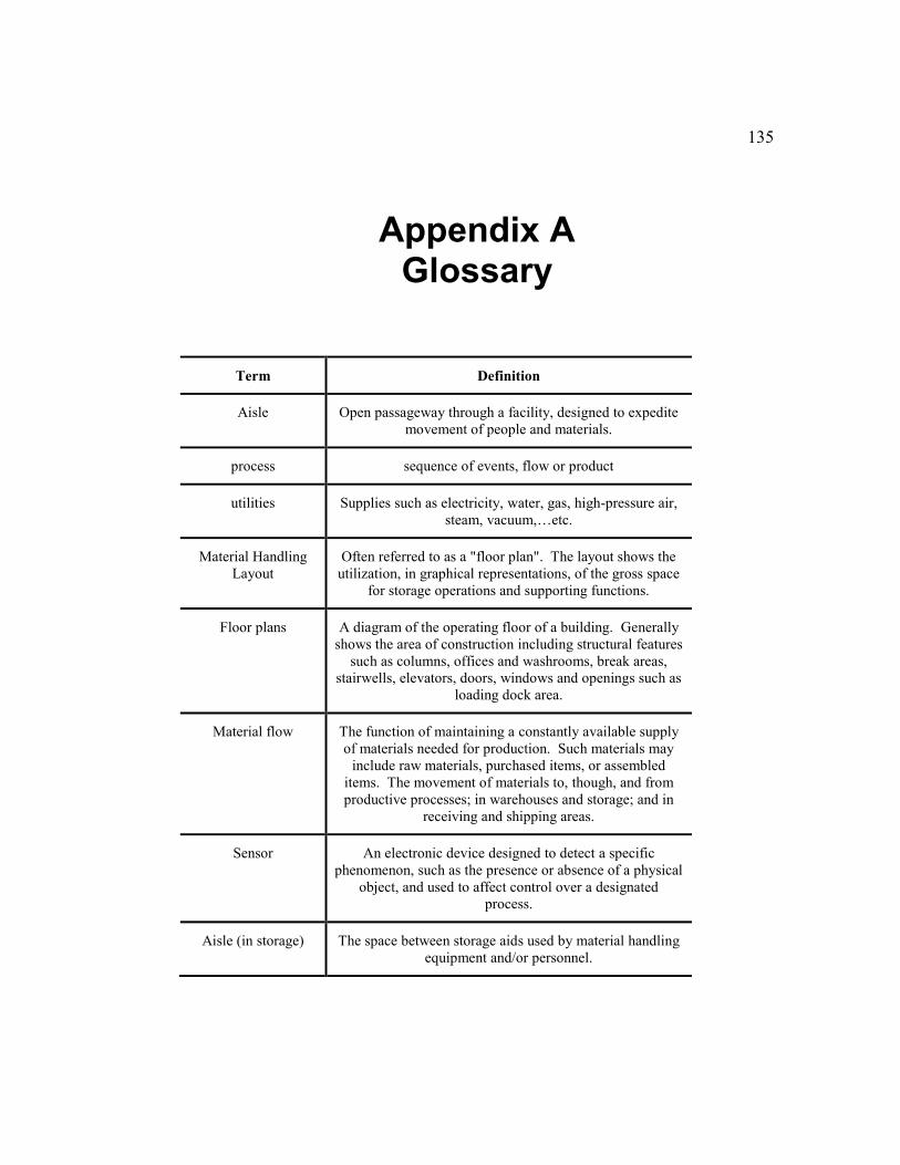
135
Appendix A Glossary
Term Definition
Aisle Open passageway through a facility, designed to expedite
movement of people and materials.
process sequence of events, flow or product
utilities Supplies such as electricity, water, gas, high-pressure air,
steam, vacuum,…etc.
Material Handling
Layout
Often referred to as a "floor plan". The layout shows the
utilization, in graphical representations, of the gross space
for storage operations and supporting functions.
Floor plans A diagram of the operating floor of a building. Generally
shows the area of construction including structural features
such as columns, offices and washrooms, break areas,
stairwells, elevators, doors, windows and openings such as
loading dock area.
Material flow The function of maintaining a constantly available supply
of materials needed for production. Such materials may
include raw materials, purchased items, or assembled
items. The movement of materials to, though, and from
productive processes; in warehouses and storage; and in
receiving and shipping areas.
Sensor An electronic device designed to detect a specific
phenomenon, such as the presence or absence of a physical
object, and used to affect control over a designated
process.
Aisle (in storage) The space between storage aids used by material handling
equipment and/or personnel.
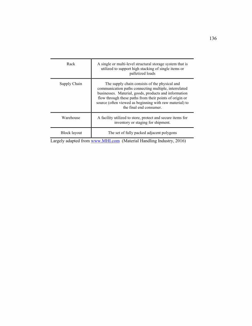
136
Rack A single or multi-level structural storage system that is
utilized to support high stacking of single items or
palletized loads
Supply Chain The supply chain consists of the physical and
communication paths connecting multiple, interrelated
businesses. Material, goods, products and information
flow through these paths from their points of origin or
source (often viewed as beginning with raw material) to
the final end consumer.
Warehouse A facility utilized to store, protect and secure items for
inventory or staging for shipment.
Block layout The set of fully packed adjacent polygons
Largely adapted from www.MHI.com (Material Handling Industry, 2016)
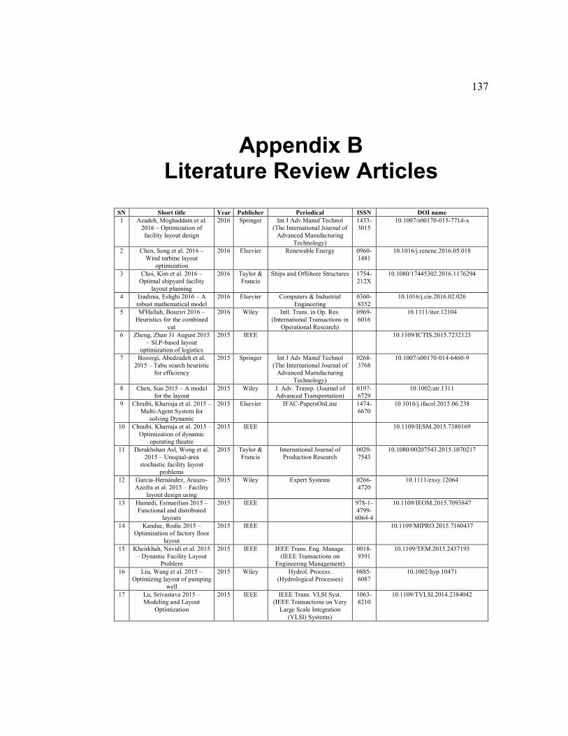
137
Appendix B Literature Review Articles
SN Short title Year Publisher Periodical ISSN DOI name
1 Azadeh, Moghaddam et al.
2016 – Optimization of
facility layout design
2016 Springer Int J Adv Manuf Technol
(The International Journal of
Advanced Manufacturing
Technology)
1433-
3015
10.1007/s00170-015-7714-x
2 Chen, Song et al. 2016 –
Wind turbine layout
optimization
2016 Elsevier Renewable Energy 0960-
1481
10.1016/j.renene.2016.05.018
3 Choi, Kim et al. 2016 –
Optimal shipyard facility
layout planning
2016 Taylor &
Francis
Ships and Offshore Structures 1754-
212X
10.1080/17445302.2016.1176294
4 Izadinia, Eshghi 2016 – A
robust mathematical model
2016 Elsevier Computers & Industrial
Engineering
0360-
8352
10.1016/j.cie.2016.02.026
5 M'Hallah, Bouziri 2016 –
Heuristics for the combined
cut
2016 Wiley Intl. Trans. in Op. Res.
(International Transactions in
Operational Research)
0969-
6016
10.1111/itor.12104
6 Zheng, Zhan 31 August 2015
– SLP-based layout
optimization of logistics
2015 IEEE
10.1109/ICTIS.2015.7232123
7 Bozorgi, Abedzadeh et al.
2015 – Tabu search heuristic
for efficiency
2015 Springer Int J Adv Manuf Technol
(The International Journal of
Advanced Manufacturing
Technology)
0268-
3768
10.1007/s00170-014-6460-9
8 Chen, Sun 2015 – A model
for the layout
2015 Wiley J. Adv. Transp. (Journal of
Advanced Transportation)
0197-
6729
10.1002/atr.1311
9 Chraibi, Kharraja et al. 2015 –
Multi-Agent System for
solving Dynamic
2015 Elsevier IFAC-PapersOnLine 1474-
6670
10.1016/j.ifacol.2015.06.238
10 Chraibi, Kharraja et al. 2015 –
Optimization of dynamic
operating theatre
2015 IEEE
10.1109/IESM.2015.7380169
11 Derakhshan Asl, Wong et al.
2015 – Unequal-area
stochastic facility layout
problems
2015 Taylor &
Francis
International Journal of
Production Research
0020-
7543
10.1080/00207543.2015.1070217
12 García-Hernández, Arauzo-
Azofra et al. 2015 – Facility
layout design using
2015 Wiley Expert Systems 0266-
4720
10.1111/exsy.12064
13 Hamedi, Esmaeilian 2015 –
Functional and distributed
layouts
2015 IEEE
978-1-
4799-
6064-4
10.1109/IEOM.2015.7093847
14 Kanduc, Rodic 2015 –
Optimisation of factory floor
layout
2015 IEEE
10.1109/MIPRO.2015.7160437
15 Kheirkhah, Navidi et al. 2015
– Dynamic Facility Layout
Problem
2015 IEEE IEEE Trans. Eng. Manage.
(IEEE Transactions on
Engineering Management)
0018-
9391
10.1109/TEM.2015.2437195
16 Liu, Wang et al. 2015 –
Optimizing layout of pumping
well
2015 Wiley Hydrol. Process.
(Hydrological Processes)
0885-
6087
10.1002/hyp.10471
17 Lu, Srivastava 2015 –
Modeling and Layout
Optimization
2015 IEEE IEEE Trans. VLSI Syst.
(IEEE Transactions on Very
Large Scale Integration
(VLSI) Systems)
1063-
8210
10.1109/TVLSI.2014.2384042
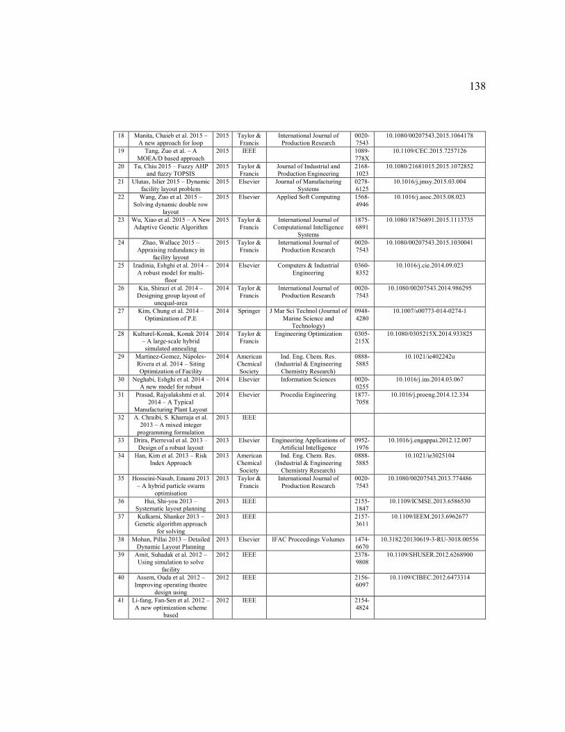
138
18 Manita, Chaieb et al. 2015 –
A new approach for loop
2015 Taylor &
Francis
International Journal of
Production Research
0020-
7543
10.1080/00207543.2015.1064178
19 Tang, Zuo et al. – A
MOEA/D based approach
2015 IEEE
1089-
778X
10.1109/CEC.2015.7257126
20 Tu, Chiu 2015 – Fuzzy AHP
and fuzzy TOPSIS
2015 Taylor &
Francis
Journal of Industrial and
Production Engineering
2168-
1023
10.1080/21681015.2015.1072852
21 Ulutas, Islier 2015 – Dynamic
facility layout problem
2015 Elsevier Journal of Manufacturing
Systems
0278-
6125
10.1016/j.jmsy.2015.03.004
22 Wang, Zuo et al. 2015 –
Solving dynamic double row
layout
2015 Elsevier Applied Soft Computing 1568-
4946
10.1016/j.asoc.2015.08.023
23 Wu, Xiao et al. 2015 – A New
Adaptive Genetic Algorithm
2015 Taylor &
Francis
International Journal of
Computational Intelligence
Systems
1875-
6891
10.1080/18756891.2015.1113735
24 Zhao, Wallace 2015 –
Appraising redundancy in
facility layout
2015 Taylor &
Francis
International Journal of
Production Research
0020-
7543
10.1080/00207543.2015.1030041
25 Izadinia, Eshghi et al. 2014 –
A robust model for multi-
floor
2014 Elsevier Computers & Industrial
Engineering
0360-
8352
10.1016/j.cie.2014.09.023
26 Kia, Shirazi et al. 2014 –
Designing group layout of
unequal-area
2014 Taylor &
Francis
International Journal of
Production Research
0020-
7543
10.1080/00207543.2014.986295
27 Kim, Chung et al. 2014 –
Optimization of P.E
2014 Springer J Mar Sci Technol (Journal of
Marine Science and
Technology)
0948-
4280
10.1007/s00773-014-0274-1
28 Kulturel-Konak, Konak 2014
– A large-scale hybrid
simulated annealing
2014 Taylor &
Francis
Engineering Optimization 0305-
215X
10.1080/0305215X.2014.933825
29 Martinez-Gomez, Nápoles-
Rivera et al. 2014 – Siting
Optimization of Facility
2014 American
Chemical
Society
Ind. Eng. Chem. Res.
(Industrial & Engineering
Chemistry Research)
0888-
5885
10.1021/ie402242u
30 Neghabi, Eshghi et al. 2014 –
A new model for robust
2014 Elsevier Information Sciences 0020-
0255
10.1016/j.ins.2014.03.067
31 Prasad, Rajyalakshmi et al.
2014 – A Typical
Manufacturing Plant Layout
2014 Elsevier Procedia Engineering 1877-
7058
10.1016/j.proeng.2014.12.334
32 A. Chraibi, S. Kharraja et al.
2013 – A mixed integer
programming formulation
2013 IEEE
33 Drira, Pierreval et al. 2013 –
Design of a robust layout
2013 Elsevier Engineering Applications of
Artificial Intelligence
0952-
1976
10.1016/j.engappai.2012.12.007
34 Han, Kim et al. 2013 – Risk
Index Approach
2013 American
Chemical
Society
Ind. Eng. Chem. Res.
(Industrial & Engineering
Chemistry Research)
0888-
5885
10.1021/ie3025104
35 Hosseini-Nasab, Emami 2013
– A hybrid particle swarm
optimisation
2013 Taylor &
Francis
International Journal of
Production Research
0020-
7543
10.1080/00207543.2013.774486
36 Hui, Shi-you 2013 –
Systematic layout planning
2013 IEEE
2155-
1847
10.1109/ICMSE.2013.6586530
37 Kulkarni, Shanker 2013 –
Genetic algorithm approach
for solving
2013 IEEE
2157-
3611
10.1109/IEEM.2013.6962677
38 Mohan, Pillai 2013 – Detailed
Dynamic Layout Planning
2013 Elsevier IFAC Proceedings Volumes 1474-
6670
10.3182/20130619-3-RU-3018.00556
39 Amit, Suhadak et al. 2012 –
Using simulation to solve
facility
2012 IEEE
2378-
9808
10.1109/SHUSER.2012.6268900
40 Assem, Ouda et al. 2012 –
Improving operating theatre
design using
2012 IEEE
2156-
6097
10.1109/CIBEC.2012.6473314
41 Li-fang, Fan-Sen et al. 2012 –
A new optimization scheme
based
2012 IEEE
2154-
4824
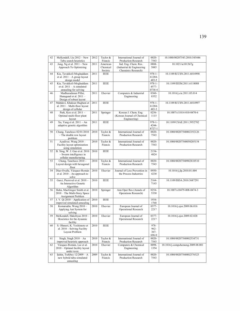
139
42 McKendall, Liu 2012 – New
Tabu search heuristics
2012 Taylor &
Francis
International Journal of
Production Research
0020-
7543
10.1080/00207543.2010.545446
43 Jung, Ng et al. 2011 – New
Approach To Optimizing
2011 American
Chemical
Society
Ind. Eng. Chem. Res.
(Industrial & Engineering
Chemistry Research)
0888-
5885
10.1021/ie101367g
44 Kia, Tavakkoli-Moghaddam
et al. 2011 – A group layout
design model
2011 IEEE
978-1-
61284-
485-5
10.1109/ICCSN.2011.6014998
45 Kia, Tavakkoli-Moghaddam
et al. 2011 – A simulated
annealing for solving
2011 IEEE
978-1-
4577-
0738-4
10.1109/IEEM.2011.6118088
46 Madhusudanan Pillai,
Hunagund et al. 2011 –
Design of robust layout
2011 Elsevier Computers & Industrial
Engineering
0360-
8352
10.1016/j.cie.2011.05.014
47 Mahdavi, Khaksar-Haghani et
al. 2011 – Multi-floor layout
design of cellular
2011 IEEE
978-1-
61284-
485-5
10.1109/ICCSN.2011.6014997
48 Park, Koo et al. 2011 –
Optimal multi-floor plant
layout
2011 Springer Korean J. Chem. Eng.
(Korean Journal of Chemical
Engineering)
0256-
1115
10.1007/s11814-010-0470-6
49 Xu, Yang et al. 2011 – An
adaptive genetic algorithm
2011 IEEE
978-1-
4244-
8727-1
10.1109/CSAE.2011.5952782
50 Chung, Tanchoco 02/01/2010
– The double row layout
problem
2010 Taylor &
Francis
International Journal of
Production Research
0020-
7543
10.1080/00207540802192126
51 Azadivar, Wang 2010 –
Facility layout optimization
using simulation
2010 Taylor &
Francis
International Journal of
Production Research
0020-
7543
10.1080/00207540050205154
52 B. Xing, W. J. Gao et al. 2010
– Swarm intelligence in
cellular manufacturing
2010 IEEE
2154-
4824
53 Chung, Tanchoco 2010 –
Layout design with hexagonal
floor
2010 Taylor &
Francis
International Journal of
Production Research
0020-
7543
10.1080/00207540902810510
54 Díaz-Ovalle, Vázquez-Román
et al. 2010 – An approach to
solve
2010 Elsevier Journal of Loss Prevention in
the Process Industries
0950-
4230
10.1016/j.jlp.2010.01.004
55 Garci, Pierreval et al. 2010 –
An Interactive Genetic
Algorithm
2010 IEEE
2164-
7143
10.1109/ISDA.2010.5687291
56 Hahn, MacGregor Smith et al.
2010 – The Multi-Story Space
Assignment Problem
2010 Springer Ann Oper Res (Annals of
Operations Research)
0254-
5330
10.1007/s10479-008-0474-3
57 J. Y. Qi 2010 – Application of
improved simulated annealing
2010 IEEE
1934-
1768
58 Komarudin, Wong 2010 –
Applying Ant System for
solving
2010 Elsevier European Journal of
Operational Research
0377-
2217
10.1016/j.ejor.2009.06.016
59 McKendall, Hakobyan 2010 –
Heuristics for the dynamic
facility
2010 Elsevier European Journal of
Operational Research
0377-
2217
10.1016/j.ejor.2009.02.028
60 S. Ohmori, K. Yoshimoto et
al. 2010 – Solving Facility
Layout Problem
2010 IEEE
978-
962-
367-
696-0
61 Singh, Singh 2010 – An
improved heuristic approach
2010 Taylor &
Francis
International Journal of
Production Research
0020-
7543
10.1080/00207540802534731
62 Vázquez-Román, Lee et al.
2010 – Optimal facility layout
under toxic
2010 Elsevier Computers & Chemical
Engineering
0098-
1354
10.1016/j.compchemeng.2009.08.001
63 Şahin, Txrkbey 12/2009 – A
new hybrid tabu-simulated
annealing
2009 Taylor &
Francis
International Journal of
Production Research
0020-
7543
10.1080/00207540802376323
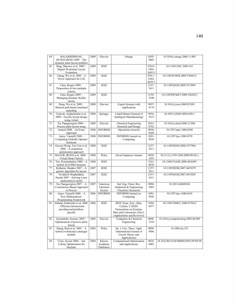
140
64 BALAKRISHNAN,
HUNGCHENG 2009 – The
dynamic plant layout problem
2009 Elsevier Omega 0305-
0483
10.1016/j.omega.2006.11.005
65 Bing, Shaowei et al. 2009 –
Digital Workshop Layout
Evaluation
2009 IEEE
978-0-
7695-
3645-3
10.1109/CINC.2009.165
66 Chang, Wu et al. 2009 – A
Novel Approach for Cell
2009 IEEE
978-1-
4244-
4639-1
10.1109/ICMSS.2009.5304612
67 Chen, Rogers 2009 –
Proposition of two multiple
criteria
2009 IEEE
2157-
3611
10.1109/IEEM.2009.5373095
68 Chen, Rogers 2009 –
Managing dynamic facility
layout
2009 IEEE
2159-
5100
10.1109/PICMET.2009.5262013
69 Dong, Wu et al. 2009 –
Shortest path based simulated
annealing
2009 Elsevier Expert Systems with
Applications
0957-
4174
10.1016/j.eswa.2009.02.091
70 Tarkesh, Atighehchian et al.
2009 – Facility layout design
using virtual
2009 Springer J Intell Manuf (Journal of
Intelligent Manufacturing)
0956-
5515
10.1007/s10845-008-0109-1
71 Xu, Papageorgiou 2009 –
Process plant layout using
2009 Elsevier Chemical Engineering
Research and Design
0263-
8762
10.1016/j.cherd.2008.12.004
72 Amaral 2008 – An Exact
Approach
2008 INFORMS Operations research 0030-
364X
10.1287/opre.1080.0548
73 Anjos, Vannelli 2008 –
Computing Globally Optimal
Solutions
2008 INFORMS INFORMS Journal on
Computing
1091-
9856
10.1287/ijoc.1080.0270
74 Guoxin Wang, Yan Yan et al.
2008 – A simulation
optimization approach
2008 IEEE
2157-
3611
10.1109/IEEM.2008.4737966
75 MAYER, IRANI et al. 2008 –
Virtual Shop Clusters
2008 Wiley Naval Engineers Journal 0028-
1425
10.1111/j.1559-3584.2008.00128.x
76 Teo, Ponnambalam 2008 – A
hybrid ACO/PSO heuristic
2008 IEEE
2161-
8070
10.1109/COASE.2008.4626491
77 Kulkarni, Shanker 2007 – A
genetic algorithm for layout
2007 IEEE
2157-
3611
10.1109/IEEM.2007.4419279
78 Tavakkoli Moghaddam,
Panahi 2007 – Solving a new
mathematical model
2007 IEEE
2157-
3611
10.1109/IEEM.2007.4419205
79 Xu, Papageorgiou 2007 – A
Construction-Based Approach
to Process
2007 American
Chemical
Society
Ind. Eng. Chem. Res.
(Industrial & Engineering
Chemistry Research)
0888-
5885
10.1021/ie060843k
80 Anjos, Vannelli 2006 – A
New Mathematical-
Programming Framework
2006 INFORMS INFORMS Journal on
Computing
1091-
9856
10.1287/ijoc.1040.0103
81 Eklund, Embrechts et al. 2006
– Efficient chromosome
encoding and problem-
specific
2006 IEEE IEEE Trans. Syst., Man,
Cybern. C (IEEE
Transactions on Systems,
Man and Cybernetics, Part C
(Applications and Reviews))
1094-
6977
10.1109/TSMCC.2006.875412
82 Guirardello, Swaney 2005 –
Optimization of process plant
layout
2005 Elsevier Computers & Chemical
Engineering
0098-
1354
10.1016/j.compchemeng.2005.08.009
83 Zhang, Raut et al. 2005 – A
hybrid evolutionary analogue
module
2005 Wiley Int. J. Circ. Theor. Appl.
(International Journal of
Circuit Theory and
Applications)
0098-
9886
10.1002/cta.332
84 Corry, Kozan 2004 – Ant
Colony Optimisation for
Machine
2004 Kluwer
Academic
Publishers
Computational Optimization
and Applications
0926-
6003
10.1023/B:COAP.0000033965.99769.98
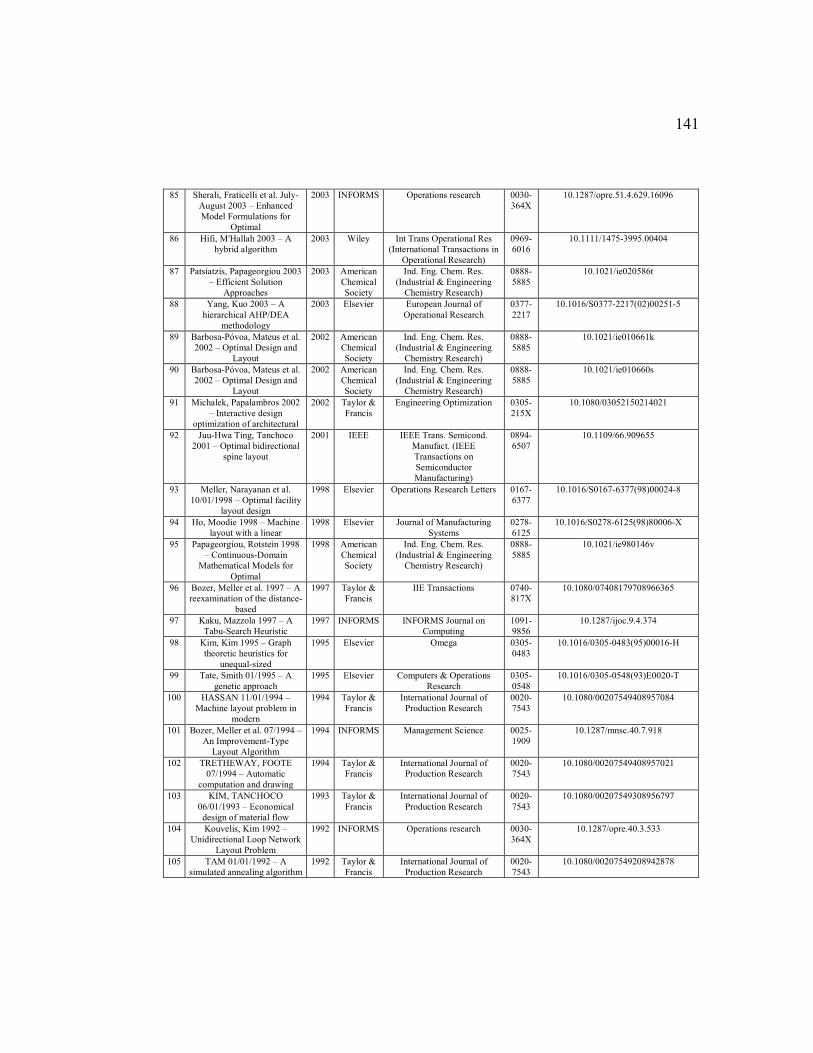
141
85 Sherali, Fraticelli et al. July-
August 2003 – Enhanced
Model Formulations for
Optimal
2003 INFORMS Operations research 0030-
364X
10.1287/opre.51.4.629.16096
86 Hifi, M'Hallah 2003 – A
hybrid algorithm
2003 Wiley Int Trans Operational Res
(International Transactions in
Operational Research)
0969-
6016
10.1111/1475-3995.00404
87 Patsiatzis, Papageorgiou 2003
– Efficient Solution
Approaches
2003 American
Chemical
Society
Ind. Eng. Chem. Res.
(Industrial & Engineering
Chemistry Research)
0888-
5885
10.1021/ie020586t
88 Yang, Kuo 2003 – A
hierarchical AHP/DEA
methodology
2003 Elsevier European Journal of
Operational Research
0377-
2217
10.1016/S0377-2217(02)00251-5
89 Barbosa-Póvoa, Mateus et al.
2002 – Optimal Design and
Layout
2002 American
Chemical
Society
Ind. Eng. Chem. Res.
(Industrial & Engineering
Chemistry Research)
0888-
5885
10.1021/ie010661k
90 Barbosa-Póvoa, Mateus et al.
2002 – Optimal Design and
Layout
2002 American
Chemical
Society
Ind. Eng. Chem. Res.
(Industrial & Engineering
Chemistry Research)
0888-
5885
10.1021/ie010660s
91 Michalek, Papalambros 2002
– Interactive design
optimization of architectural
2002 Taylor &
Francis
Engineering Optimization 0305-
215X
10.1080/03052150214021
92 Juu-Hwa Ting, Tanchoco
2001 – Optimal bidirectional
spine layout
2001 IEEE IEEE Trans. Semicond.
Manufact. (IEEE
Transactions on
Semiconductor
Manufacturing)
0894-
6507
10.1109/66.909655
93 Meller, Narayanan et al.
10/01/1998 – Optimal facility
layout design
1998 Elsevier Operations Research Letters 0167-
6377
10.1016/S0167-6377(98)00024-8
94 Ho, Moodie 1998 – Machine
layout with a linear
1998 Elsevier Journal of Manufacturing
Systems
0278-
6125
10.1016/S0278-6125(98)80006-X
95 Papageorgiou, Rotstein 1998
– Continuous-Domain
Mathematical Models for
Optimal
1998 American
Chemical
Society
Ind. Eng. Chem. Res.
(Industrial & Engineering
Chemistry Research)
0888-
5885
10.1021/ie980146v
96 Bozer, Meller et al. 1997 – A
reexamination of the distance-
based
1997 Taylor &
Francis
IIE Transactions 0740-
817X
10.1080/07408179708966365
97 Kaku, Mazzola 1997 – A
Tabu-Search Heuristic
1997 INFORMS INFORMS Journal on
Computing
1091-
9856
10.1287/ijoc.9.4.374
98 Kim, Kim 1995 – Graph
theoretic heuristics for
unequal-sized
1995 Elsevier Omega 0305-
0483
10.1016/0305-0483(95)00016-H
99 Tate, Smith 01/1995 – A
genetic approach
1995 Elsevier Computers & Operations
Research
0305-
0548
10.1016/0305-0548(93)E0020-T
100 HASSAN 11/01/1994 –
Machine layout problem in
modern
1994 Taylor &
Francis
International Journal of
Production Research
0020-
7543
10.1080/00207549408957084
101 Bozer, Meller et al. 07/1994 –
An Improvement-Type
Layout Algorithm
1994 INFORMS Management Science 0025-
1909
10.1287/mnsc.40.7.918
102 TRETHEWAY, FOOTE
07/1994 – Automatic
computation and drawing
1994 Taylor &
Francis
International Journal of
Production Research
0020-
7543
10.1080/00207549408957021
103 KIM, TANCHOCO
06/01/1993 – Economical
design of material flow
1993 Taylor &
Francis
International Journal of
Production Research
0020-
7543
10.1080/00207549308956797
104 Kouvelis, Kim 1992 –
Unidirectional Loop Network
Layout Problem
1992 INFORMS Operations research 0030-
364X
10.1287/opre.40.3.533
105 TAM 01/01/1992 – A
simulated annealing algorithm
1992 Taylor &
Francis
International Journal of
Production Research
0020-
7543
10.1080/00207549208942878
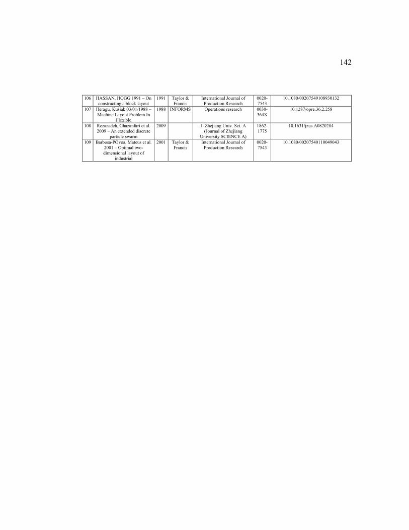
142
106 HASSAN, HOGG 1991 – On
constructing a block layout
1991 Taylor &
Francis
International Journal of
Production Research
0020-
7543
10.1080/00207549108930132
107 Heragu, Kusiak 03/01/1988 –
Machine Layout Problem In
Flexible
1988 INFORMS Operations research 0030-
364X
10.1287/opre.36.2.258
108 Rezazadeh, Ghazanfari et al.
2009 – An extended discrete
particle swarm
2009
J. Zhejiang Univ. Sci. A
(Journal of Zhejiang
University SCIENCE A)
1862-
1775
10.1631/jzus.A0820284
109 Barbosa-PÓvoa, Mateus et al.
2001 – Optimal two-
dimensional layout of
industrial
2001 Taylor &
Francis
International Journal of
Production Research
0020-
7543
10.1080/00207540110049043
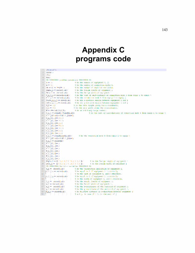
143
Appendix C programs code
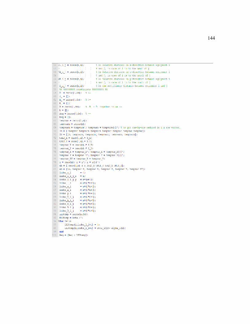
144
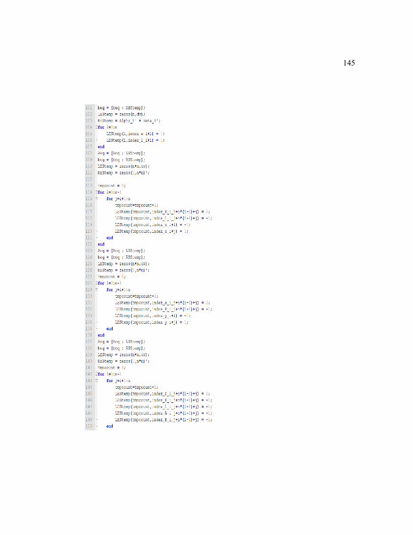
145
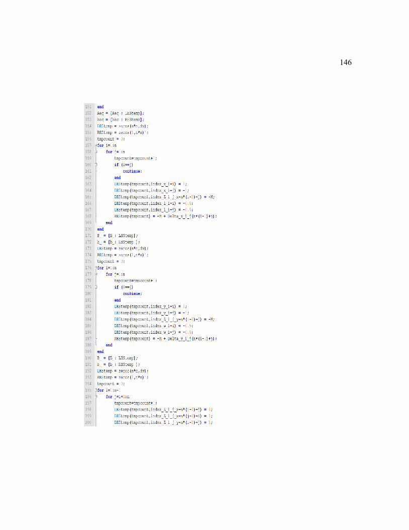
146
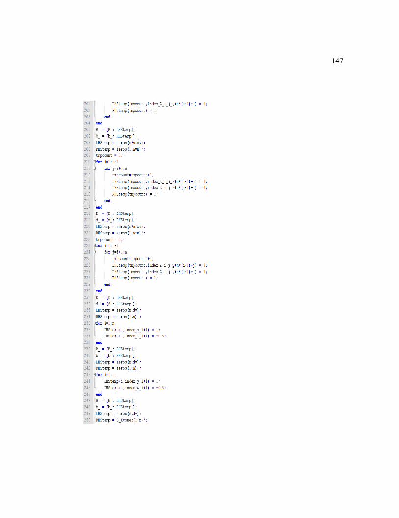
147
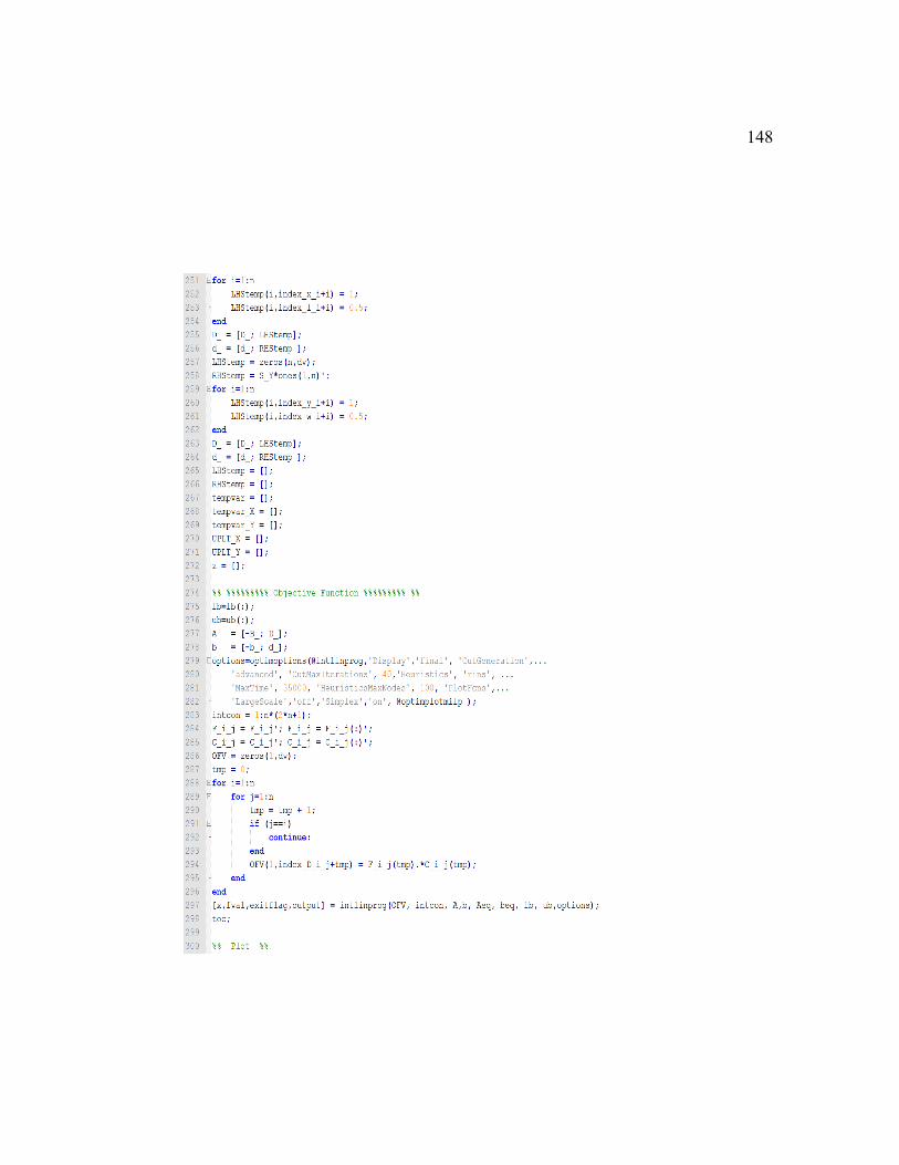
148
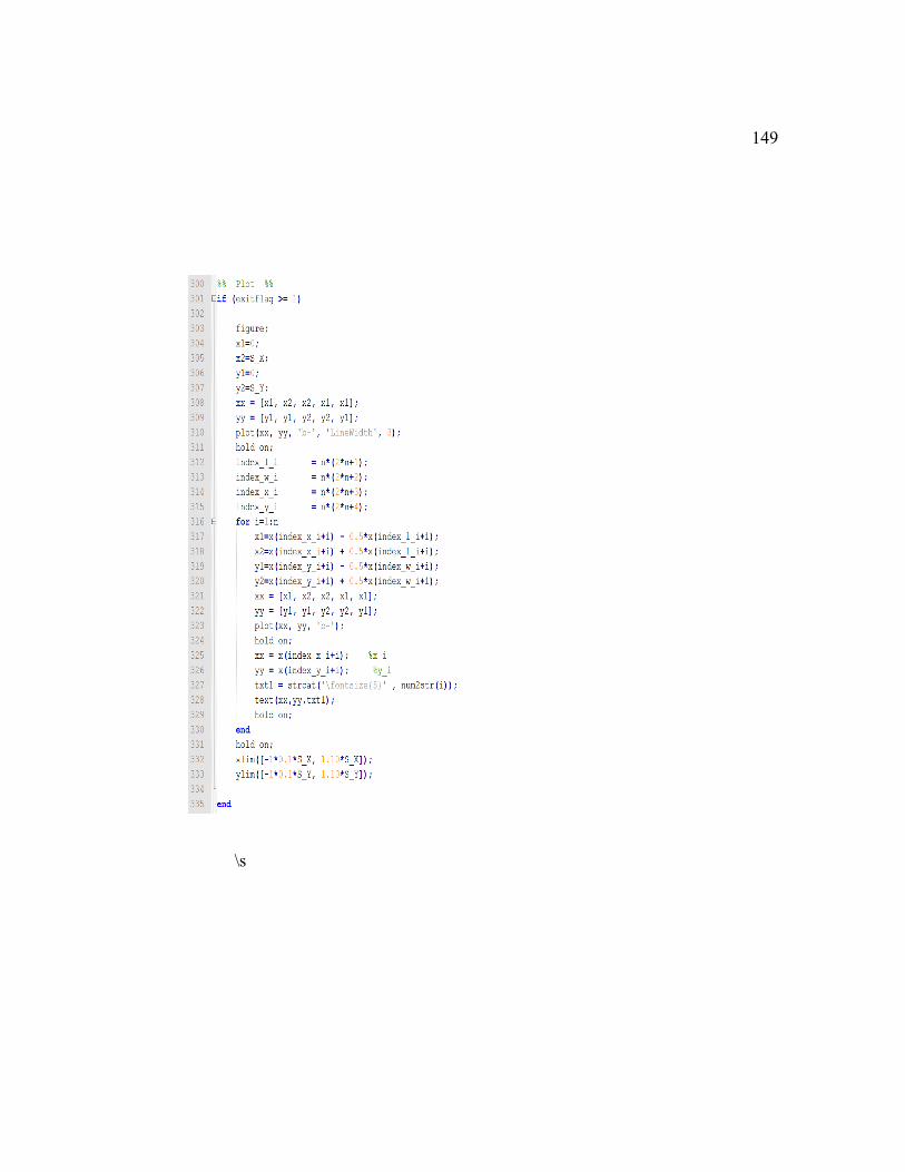
149
\s

150
Appendix E AUTOBIOGRAPHICAL
REFLECTION This research experience has been productive learning quest for me. I have
learned a significant extent of knowledge in the field of FLP and other related
fields in theories and practice. I have truthfully realized that research can be
frustrating and most of the time profoundly tedious, yet it produces rewarding
skills, knowledge, and experience. This research study has also provided me with a
new purpose which has altered my views on my own professional values and
provoked me for innovative habits to my own future practices.
Regarding the research activities, I have been through a stunning journey of
immense experience. For instance, I have been utilizing all possible online search
tools at the time of this writing like FIT Library, Scopus, Web of Science,
WorldCat, etc. I have experimented with mind mapping tools during the initial
investigations of the related topics and ideas. I have also nurtured the well to learn
and apply several tools to help me during my research. Such tools spanning
different activities related to this thesis. For instance, I used special research and
reference management tools developed by Swiss Academic Software, where I did
much of idea and thoughts organizing and referencing. I, also, have been working
on polishing my word processor’s typing skills, restoring my graphs and diagrams
editing skills, enhancing my time management with various apps, and evaluating
several programming languages platforms.

151
I have also begun to realize that much can and should be done in the arena
of Systems Engineering for FLP field. This research process has also encouraged
me to explore the subject deeply and study other related topics within a broader
field in order to improve the evolution of the facilities planning and management.

152
Vita (Curriculum Vitae) Abdulelah Saeed M. Algarni was born in Saudi Arabia Sept 30th, 1982.
The son of Saeed M. and Nora N. He graduated from Sabt Alalayah High School
in Asser Province, Saudi Arabia in 2000. He joined training program by Saudi
Aramco Oil Company after graduation. He was awarded a scholarship and joined
King Fahd University and Petroleum in 2004. 2007 August, he graduated with
BSc. in Computer Science. He worked as Process Control System Engineer.
The thesis was typed and edited by the author.
ORCID: ABDULELAH ALGARNI orcid.org/0000-0002-4431-8825