
DataEngConf SF16 - Scalable and Reliable Logging at Pinterest
1
A systemic approach toward scalable, reliable and safe satellite constellations
by
Alan Kharsansky
Electronics Engineer
University of Buenos Aires, 2013
Submitted to the System Design and Management Program
in Partial Fulfilment of the Requirements for the Degree of
Master of Science in Engineering and Management
at the
Massachusetts Institute of Technology
September 2020
© 2020 Alan Kharsansky
All rights reserved
The author hereby grants to MIT permission to reproduce and to distribute publicly paper and
electronic copies of this thesis document in whole or in part in any medium now known or hereafter created.
Signature of the author ………………………………………………………………………
System Design and Management Program
TBD, 2020
Certified by…………………………………………………………………………………….
Nancy G. Leveson
Professor of Aeronautics and Astronautics and Engineering Systems
Thesis Supervisor
Accepted by…………………………………………………………………………………… Joan S. Rubin
Executive Director MIT System Design and Management Program

2
A systemic approach toward scalable, reliable and safe satellite constellations
By
Alan Kharsansky
Submitted to the System Design and Management Program
On August 13th, 2020 in Partial Fulfilment of the Requirements for the
Degree of Master of Science in Engineering and Management
ABSTRACT
Constellations of hundreds to thousands of satellites are becoming a reality. Nevertheless,
the unprecedented scale of these systems is creating new sorts of challenges and risks for the
designers and operators, mainly due to the high level of automation required. This study
demonstrates how architectural decisions like the constellation topology, type of connectivity,
and the level of automation affect the scalability, reliability, and safety of these constellations.
A survey of past, current, and planned constellations was conducted to identify key
architectural decisions and create representative architectures to analyze using a novel process
called Conceptual Architecture Development. These high-level conceptual architectures were
refined and analyzed using Systems Theoretic Process Analysis (STPA), and a qualitative
assessment and a comparison of the emergent properties were performed.
The results suggest that increased automation improves the scalability of the system,
mostly when human controllers' responsibilities are shifted from individual satellite
management to constellation management. However, increased automation also creates new
responsibilities for human controllers and does not necessarily improve the safety and reliability
of the system. Human-related causal factors found in lower levels of automation are mostly
translated into software-related causal factors in higher levels of automation instead of being
eliminated, and new types of hazards arise from the introduction of human-automation
interfaces. Moreover, other architectural decisions, such as ground connectivity type, can
negatively impact the safety and reliability of the constellation, mostly for slightly automated
systems.
This study shows that architectural decisions can significantly affect the resulting emergent
properties of a system and that there is a tradeoff between automation, safety, and reliability
that should not be overlooked. Designers and operators should analyze this tradeoff and the
development and operational costs in order to select the best-suited architecture for their
constellations based on their expertise, technology strategy, and constellation size.
Thesis supervisor: Nancy G. Leveson
Title: Professor of Aeronautics and Astronautics and Engineering Systems

3
Acknowledgments
I would like to express my sincere gratitude to Satellogic, and in particular to Emiliano
Kargieman, for believing in me and sponsoring my graduate education. Satellogic provided me
with the most remarkable professional experiences I could imagine and helped me pave my
way into the space industry.
I would also like to thank my thesis supervisor, Professor Nancy Leveson, for showing me
a completely new way to see systems engineering, in particular regarding complex socio-
technical systems. Her view of complex systems in our ever-changing world profoundly changed
how I see the world and was a great inspiration for this work.
I’m extremely grateful to my wife Yasmin for her unconditional support, love, and
encouragement to pursue this degree and for joining me in this adventure. She gave all of her
for the family and provided the love and care that we needed. It wouldn’t have been possible
without her. Also, I would like to thank my little son, Ben, who joined us on this journey and
who makes our lives happier every day.
I’m also deeply indebted to my parents Adriana and Gabriel, who set me off on the road
to this degree a long time ago giving me all possible love and support and teaching me that
with effort almost everything is possible. They, along with my sister Melina, provided me and
my family all the support needed while living abroad.
Finally, I would like to thank my friend and colleague David Vilaseca for our endless
conversations about my research and his valuable advice, as well as my friend Michel Peterson
who guided me through the academic world with ease. I would also like to thank my classmate
Brandon Baylor, and Federico Jack for their valuable advice.

4
Table of contents
Acknowledgments ....................................................................................................................... 3
Table of contents........................................................................................................................ 4
List of figures ............................................................................................................................. 7
List of tables ............................................................................................................................... 8
Chapter 1: Introduction ........................................................................................................... 10
1.1. Motivation ..................................................................................................................... 10
1.2. Thesis objective ............................................................................................................. 13
1.3. Thesis structure ............................................................................................................. 13
Chapter 2: Background ............................................................................................................ 15
2.1. Introduction ................................................................................................................... 15
2.2. Taxonomy and definition of constellation ..................................................................... 15
2.3. Legal and regulatory framework.................................................................................... 16
2.4. Literature review ........................................................................................................... 20
2.4.1. Constellation Topology ........................................................................................... 20
2.4.2. In-orbit collisions .................................................................................................... 20
2.4.3. Satellite and constellation architecture .................................................................. 21
2.4.4. Automation ............................................................................................................. 22
2.4.5. Systems engineering ................................................................................................ 25
2.5. Case studies and lessons learned ................................................................................... 29
2.6. Conclusion ..................................................................................................................... 31
Chapter 3: Methodology and design ........................................................................................ 33
3.1. Introduction ................................................................................................................... 33
3.2. Theoretical framework and tools selection .................................................................... 33
3.3. Survey of satellite constellations ................................................................................... 35
3.4. Architectures selection ................................................................................................... 36
3.4.1. Key architectural decisions ..................................................................................... 36
3.4.2. Architectures selection ............................................................................................ 38
3.5. Analysis process ............................................................................................................. 40
3.5.1. Purpose of the analysis ........................................................................................... 41
3.5.2. Control structure definition .................................................................................... 42
3.5.3. Identification of unsafe control actions (UCA) ...................................................... 44
3.5.4. Identification of loss scenarios and causal factors .................................................. 44
5
3.5.5. Architecture analysis and comparison .................................................................... 46
3.6. Conclusion ..................................................................................................................... 47
Chapter 4: Data and analysis .................................................................................................. 49
4.1. Chapter overview ........................................................................................................... 49
4.2. System definition and goal ............................................................................................ 49
4.3. Concept of operations .................................................................................................... 50
4.4. Losses and hazards ........................................................................................................ 53
4.5. Architecture A1 ............................................................................................................. 56
4.5.1. Control structure .................................................................................................... 56
4.5.2. Unsafe control actions ............................................................................................. 68
4.5.3. Causal scenarios ...................................................................................................... 71
4.5.4. Architecture conclusions ......................................................................................... 74
4.6. Architecture A2 ............................................................................................................. 76
4.6.1. Control structure .................................................................................................... 76
4.6.2. Unsafe control actions ............................................................................................. 84
4.6.3. Causal Scenarios ..................................................................................................... 85
4.6.4. Architecture conclusions ......................................................................................... 88
4.7. Architecture A3 ............................................................................................................. 89
4.7.1. Control structure .................................................................................................... 89
4.7.2. Unsafe control actions ............................................................................................. 94
4.7.3. Causal scenarios ...................................................................................................... 97
4.7.4. Architecture conclusions ....................................................................................... 100
4.8. Architecture comparison .............................................................................................. 101
Chapter 5: Conclusions, recommendations and future work ................................................. 105
Chapter 6: References ............................................................................................................ 109
Appendix A ............................................................................................................................ 114
Constellation database ....................................................................................................... 114
Sources ................................................................................................................................ 115
Appendix B ............................................................................................................................ 116
Constellation topology examples ........................................................................................ 116
Appendix C – Architecture A1 .............................................................................................. 119
Unsafe control actions table ............................................................................................... 119

6
Causal scenarios .................................................................................................................. 127
Network diagram ................................................................................................................ 162
Appendix D – Architecture A2 .............................................................................................. 163
Unsafe control actions table ............................................................................................... 163
Causal scenarios .................................................................................................................. 167
Network diagram ................................................................................................................ 184
Appendix E – Architecture A3 .............................................................................................. 185
Unsafe control actions table ............................................................................................... 185
Component-level constraints .............................................................................................. 192
Causal scenarios .................................................................................................................. 192
Network diagram ................................................................................................................ 204

7
List of figures
Figure 1 - Constellation member satellites launched per year as of June 2020 ...................... 10
Figure 2 - Satellites launched per constellation and colored by year of launch ...................... 12
Figure 3 – Left: GPS constellation. Right: A-Train constellation. ......................................... 16
Figure 4 – Comparison of registered satellites launched into space ........................................ 17
Figure 5 - Types of complex systems. ...................................................................................... 26
Figure 6 – Left: A generic control loop, Right: A generic hierarchical control structure ....... 34
Figure 7 - Improved systems engineering V-model. Adapted from ......................................... 35
Figure 8 – Overview of the basic STPA Method .................................................................... 40
Figure 9 - A generic conceptual architecture ........................................................................... 42
Figure 10 - Two types of scenarios .......................................................................................... 45
Figure 11 - Causal factors that can lead to unsafe control actions and hazards .................... 46
Figure 12 – Complete process, adapted from .......................................................................... 48
Figure 13 – Sample system overview of a satellite system. ..................................................... 51
Figure 14 - System lifecycle ..................................................................................................... 51
Figure 15 - High-level operational modes of each satellite ...................................................... 52
Figure 16 - A1 conceptual control structure ............................................................................ 58
Figure 17 - Propulsion subsystem operating modes ................................................................ 60
Figure 18 - A1: Summary of causal factors ............................................................................. 74
Figure 19 - A2 conceptual control structure ............................................................................ 78
Figure 20 - OBC Operating modes .......................................................................................... 79
Figure 21 - A2: summary of causal factors .............................................................................. 87
Figure 22 – A3: Conceptual control structure ......................................................................... 90
Figure 23 - A3: causal scenarios summary ............................................................................ 100
Figure 24 - Comparison of causal factors .............................................................................. 102
Figure 25 - Loose shape constellation in operations example ................................................ 116
Figure 26 - Operational tight shape constellation example ................................................... 117
Figure 27 - Early stages of a constellation deployment example .......................................... 117
Figure 28 - Tight shape constellation in deployment example .............................................. 118
Figure 29 - A1 STPA Network diagram ................................................................................ 162
Figure 30 - A2 STPA Network diagram ................................................................................ 184
Figure 31 - A3 STPA Network diagram ................................................................................ 204

8
List of tables
Table 1 – Comparison of different operators approach to operations ..................................... 30
Table 2 - Manpower per satellite ............................................................................................. 31
Table 3 - Satellite constellation morphological matrix ............................................................ 36
Table 4 - Level of Automation options .................................................................................... 38
Table 5 - Architectures under analysis .................................................................................... 40
Table 6 – System goal definition ............................................................................................. 49
Table 7 – Environmental constraints ...................................................................................... 50
Table 8 - System losses definition ............................................................................................ 54
Table 9 - System hazards ......................................................................................................... 54
Table 10 - System-level constraints ......................................................................................... 55
Table 11 - Burn plane example ................................................................................................ 66
Table 12 - A1 UCA Table summary ....................................................................................... 69
Table 13 - A1 Component level constraints ............................................................................ 71
Table 14 – A2 and A1 UCA Table comparison ...................................................................... 84
Table 15 - A2 UCA table fragment ......................................................................................... 85
Table 16 – A2 Component level constraints ........................................................................... 85
Table 17 – Example comparison of scenarios of A1 and A2 ................................................... 86
Table 18 – A3 and A2 UCA Table comparison ...................................................................... 95
Table 19 - Fragment of UCA table for architecture A3 .......................................................... 96
Table 20 – A3 Component level constraints ........................................................................... 96
Table 21 - A2 and A3 example UCAs comparison .................................................................. 97
Table 22 - A3: Example causal scenarios ................................................................................ 99
Table 23 – Impact of architectural decisions in system properties ....................................... 104
Table 24 - Satellite constellations database main entries ...................................................... 115
Table 25 - A1 UCA TableComponent-level constraints ........................................................ 122
Table 26 - A1 Component-level constraints .......................................................................... 127
Table 27 - A1 UCA related Causal scenarios ........................................................................ 156
Table 28 - A1 Non-UCA causal scenarios ............................................................................. 162
Table 29 – A2 UCA Table ..................................................................................................... 167
Table 30 - A2 UCA related casual scenarios ......................................................................... 181
Table 31 - A2 Non UCA causal scenarios ............................................................................. 183
Table 32 - A3 UCA Table ..................................................................................................... 191
Table 33 - A3 Component-level constraints .......................................................................... 192
Table 34 - A3 UCA Related causal scenarios ........................................................................ 201

9
Table 35 - A3 Non UCA causal scenarios ............................................................................. 203
10
Chapter 1: Introduction
1.1. Motivation
As of June 2020, more satellites have been launched as part of a constellation than any
previous year. From the 2666 active satellites in orbit (Union of Concerned Scientists, 2020),
approximately 42% are part of a constellation, and this figure is soaring as a consequence of
the increment in number and size of new constellations. Besides, more than 20,000 satellites
are planned to be launched by the end of the decade.
Satellites constellations have been developed since the 1960s with different impacts in
roughly three different eras (Foreman, 2018). The early era lasted from 1957 to 1996, and
constellations of just a few satellites characterized it in orbit at the same time. Governments
exclusively ran them for civil and military use. Most of these satellites worked independently
of each other, providing a service based on their aggregated coverage. The next era of
constellations, called the first-generation, lasted from 1997 to 2009. It was characterized by
the deployment of dozens of interconnected communication satellites providing global
coverage. Nevertheless, many of these companies suffered from economic difficulties caused by
high development, deployment, and operation costs and limited demand (Daehnick et al.,
2020), and the constellation development remained relatively dormant.
However, circa 2009, a second-generation of satellite constellation appeared, driven by a
reduction of launch costs, improved computing power, reduced costs of electronics, and
increased market demand for connectivity and geospatial data. This context allowed the
reawakening of these systems into what is known today as mega-constellations formed by
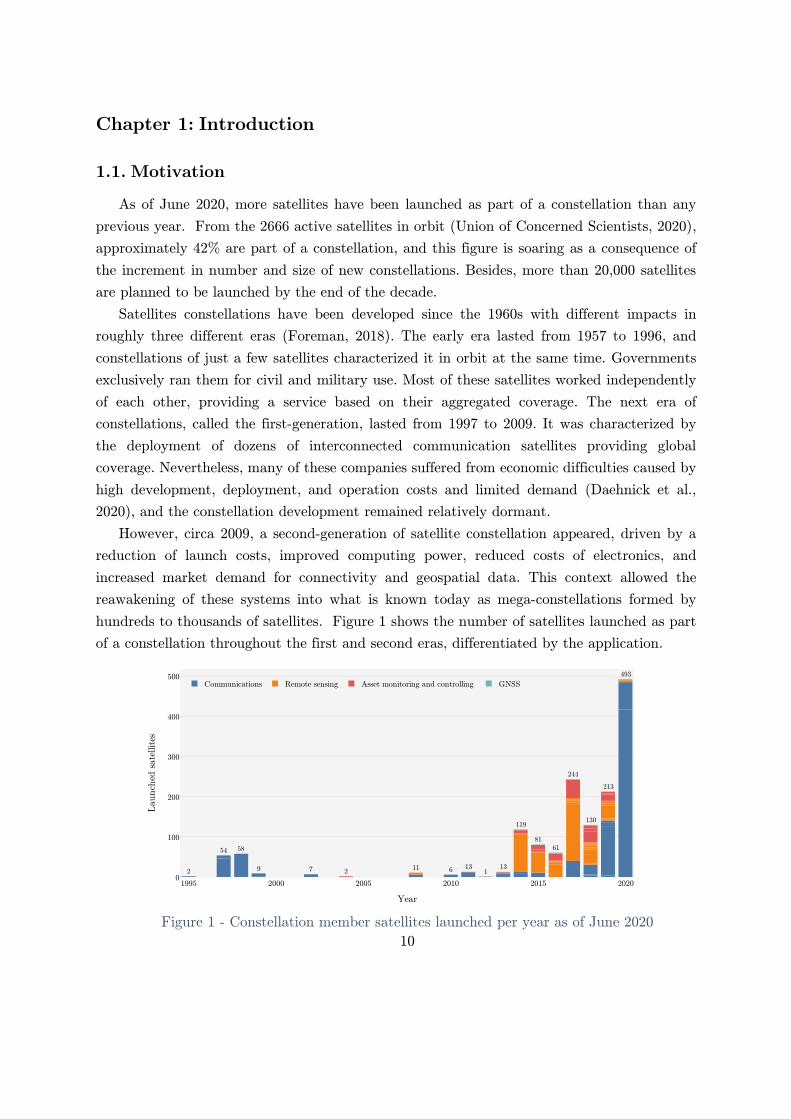
hundreds to thousands of satellites. Figure 1 shows the number of satellites launched as part
of a constellation throughout the first and second eras, differentiated by the application.
Figure 1 - Constellation member satellites launched per year as of June 2020

11
Due to this unprecedented increment in the number of satellites, the sustainable use of the
space environment is becoming a rising concern. Some operators are planning to launch
thousands of satellites into orbit, even more than the total actual population of today’s Earth
orbit, and it is not clear yet what consequences it will have. Fortunately, the number of studies
related to assessing the probability of in-orbit collisions, debris generation, and interference
with human activities is rising (Radtke et al., 2017; Drmola & Hubik, 2018; McDowell, 2020).
However, little is said about the challenges and risks that these incredibly complex systems
might have for the operators.
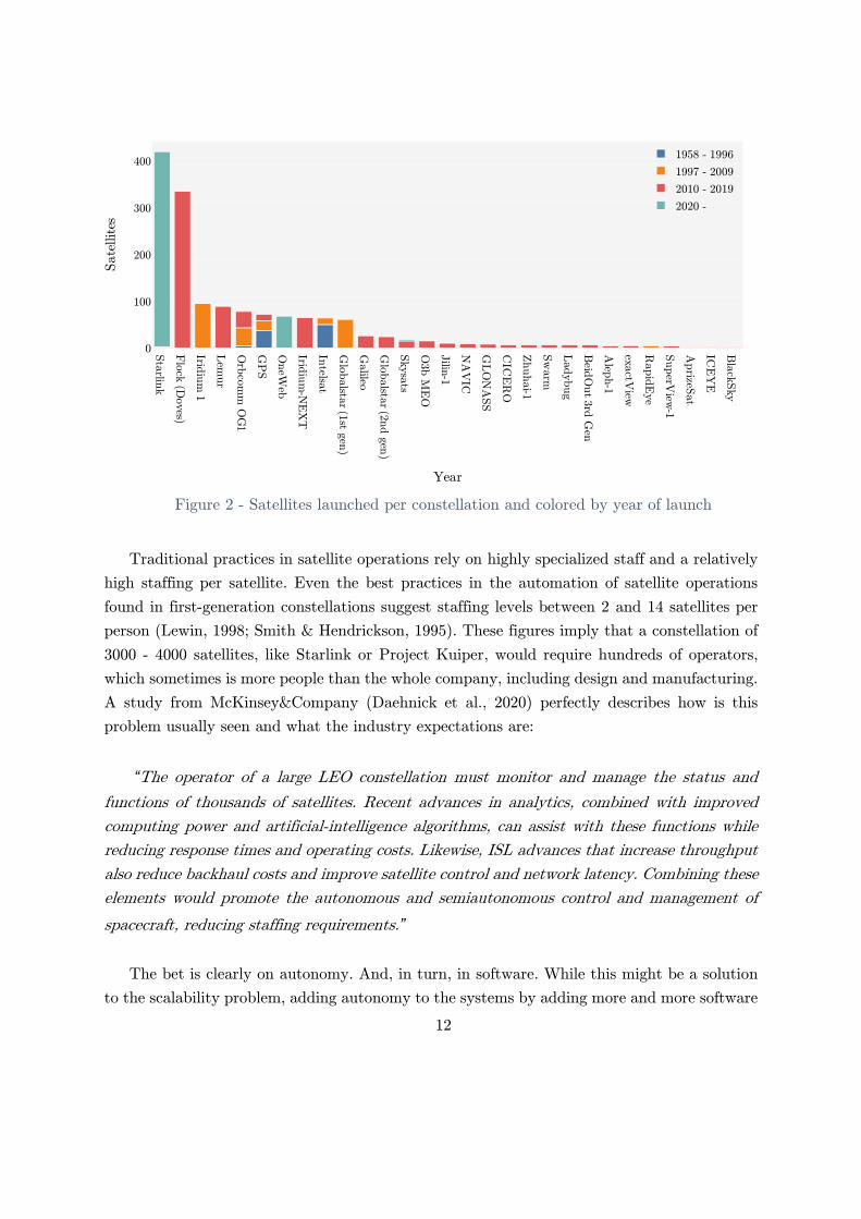
Not only is the number of different constellations is rising but the size of each of these new
mega-constellations is also climbing. Figure 2 shows a comparison of the size of satellite
constellations that have already been launched. While this is just a small sample of current
plans, an increasing trend is noticeable. Furthermore, all of the currently announced mega-
constellations are proposed by private and for-profit companies. Due to this nature, what
operators expect from them is slightly different from previous government-run missions, being
overall system reliability one of the most important. Service outages are a threat to the
profitability and success of these constellations.
While the reliability of individual satellites has been deeply investigated and perfectioned,
in-orbit failures are an everyday occurrence, and the increasing number of interconnections
and dependencies in these systems opens the door to new sources of problems. One approach,
used in many of these constellations, is to have system-level redundancy by adding more
satellites to the constellation. However, this approach is threatened by systemic design and
implementation flaws that might easily jeopardize the reliability of the entire system.
Likewise, operators are (or should be) looking for a safe system. Safety in this context is
two-fold: not having accidents that might result in economic losses for the companies as well
as avoiding accidents that might damage other assets or people in-orbit or ground.
Finally, and perhaps the most critical aspect concerning profitability is how scalable these
systems are.
12
Figure 2 - Satellites launched per constellation and colored by year of launch
Traditional practices in satellite operations rely on highly specialized staff and a relatively
high staffing per satellite. Even the best practices in the automation of satellite operations
found in first-generation constellations suggest staffing levels between 2 and 14 satellites per
person (Lewin, 1998; Smith & Hendrickson, 1995). These figures imply that a constellation of
3000 - 4000 satellites, like Starlink or Project Kuiper, would require hundreds of operators,
which sometimes is more people than the whole company, including design and manufacturing.
A study from McKinsey&Company (Daehnick et al., 2020) perfectly describes how is this
problem usually seen and what the industry expectations are:
“The operator of a large LEO constellation must monitor and manage the status and
functions of thousands of satellites. Recent advances in analytics, combined with improved
computing power and artificial-intelligence algorithms, can assist with these functions while
reducing response times and operating costs. Likewise, ISL advances that increase throughput
also reduce backhaul costs and improve satellite control and network latency. Combining these
elements would promote the autonomous and semiautonomous control and management of
spacecraft, reducing staffing requirements.”
The bet is clearly on autonomy. And, in turn, in software. While this might be a solution
to the scalability problem, adding autonomy to the systems by adding more and more software

13
to replace humans’ tasks is not trivial and is not a guarantee of success neither. The increased
complexity and coupling of highly automated and software-intensive systems can lead to a new
type of accidents (N. Leveson, 2004; N. G. Leveson, 2004) not caused by the failure of any of
its components but as a result of complex interactions between them. Then, the hypothesis is
that the reliability, scalability, and safety of these satellite constellation systems are actually
in tension, and a trade-off exists between them.
1.2. Thesis objective
While having a good system architecture is not enough to guarantee the successful
development and operation of a complex system, not having a good architecture is almost a
guarantee for failure. Architectures are mostly defined by critical architectural decisions that
are made, consciously or unconsciously, at the early stages of the design. These decisions are
the most impactful drivers of emergent properties of the system, like reliability, safety, or cost.
The remainder of the development process is based on them, and over time they become almost
impossible or unpractical to change. If, during system integration, verification, validation, or
even operations, these emergent properties turn out not to be as expected, unfortunately, there
is little that can be done.
Based on this idea, the objective of this thesis is to understand how the architecture of a
satellite constellation defines the emergent properties of reliability, scalability, and safety and
to generate guidelines and recommendations to aid the design of future satellite constellations.
The guiding research questions used throughout the process were:
- How architectural decisions influence the emergent properties of safety, reliability, and
scalability of a satellite constellation?
- How does the number of satellites in a constellation affect these properties of the
system?
1.3. Thesis structure
Chapter 2 introduces the background and context of this work. It starts with definitions
used through this work, followed by a brief description of the legal and regulatory framework
for space operators and their impact on constellation design and operations. Then, a literature
review section includes the most relevant scientific research regarding satellite constellations
design and operation. Finally, case studies are presented and analyzed from real-word satellite
constellation operators.
Chapter 3 describes the methodology and design of the experiments done for this work.
First, the theoretical framework is described, followed by the details of a survey conducted of

14
past, current, and future satellite constellations. Finally, the process used to analyze the
satellite constellation design is described.
Chapter 4 presents the results obtained by applying the methodology presented in chapter
3. First, a description of the system under study is included. It is followed by the results of
the analysis of the different architectures. Finally, a comparison between each architecture’s
result is presented.
Chapter 5 outlines the conclusions, recommendations, and future work derived from the
analysis.
Bibliographical references are included at the end of the document, followed by the
appendices that include detailed results of the process as well as supplementary information.

15
Chapter 2: Background
2.1. Introduction
Satellite constellations are incredibly complex systems consisting of multiple components
and facets. Like with any other complex system, a multiplicity of disciplines is involved in the
design and operation of such systems. This chapter starts with the taxonomy and definition of
a constellation. Then, the legal and regulatory framework is presented. This framework is
fundamental because the presence or lack of regulations can shape dramatically how a system
is designed and operated. Some of these regulations are used later as constraints in the research.
Next, a literature review is included. In this review, the fundamental topics concerning the
design and operations of satellite constellations are covered: Constellation topology, In-orbit
collisions, satellite and constellations architecture, autonomy, and different aspects of systems
engineering. Finally, an analysis of case studies and lessons learned is presented. These real-
world experiences help to understand the challenges of designing and operating satellite
constellations that operators faced in the past.
2.2. Taxonomy and definition of constellation
The definition of what a satellite constellation is an open discussion. Many different types
of missions can be categorized under this broad concept, and at the same time, they can also
be considered particular cases of a distributed satellite mission. Some authors differentiate
between constellations, formation-flying, clusters, or swarms depending on their respective
orbital parameters, their interconnection, or how they operate as a whole (Foreman, 2018).
Nevertheless, the broader definition that is used in this work is that a constellation is a “set of
satellites distributed over space intended to work together to achieve common objectives”
(Wertz et al., 2011). The differences between each subtype of constellation or satellite
distribution are irrelevant for this work and were not considered. For example, Iridium is a
constellation consisting of 75 low Earth orbit (LEO) satellites interconnected through inter-
satellite links (ISL) that has a fixed satellite distribution (shape).
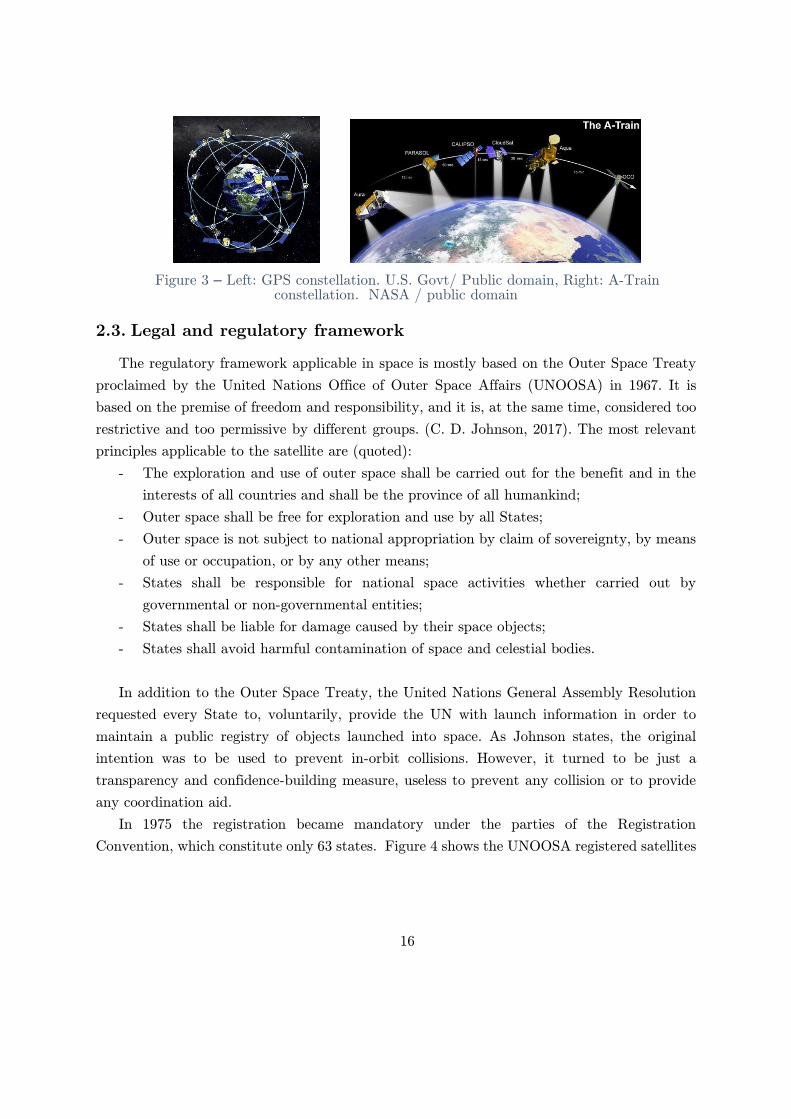
Similarly, the Global positioning system in medium Earth orbit (MEO) (Figure 3 left) or
NASA’s A-train consisting of 6 completely different satellites flying in a very tight and close
formation (Figure 3 right) are also constellations by this definition. Finally, a member satellite
of a constellation is defined as a satellite that is part of the system. At the same time, a non-
member is any other orbiting body, not part of the system.
16
Figure 3 – Left: GPS constellation. U.S. Govt/ Public domain, Right: A-Train constellation. NASA / public domain
2.3. Legal and regulatory framework
The regulatory framework applicable in space is mostly based on the Outer Space Treaty
proclaimed by the United Nations Office of Outer Space Affairs (UNOOSA) in 1967. It is
based on the premise of freedom and responsibility, and it is, at the same time, considered too
restrictive and too permissive by different groups. (C. D. Johnson, 2017). The most relevant
principles applicable to the satellite are (quoted):
- The exploration and use of outer space shall be carried out for the benefit and in the
interests of all countries and shall be the province of all humankind;
- Outer space shall be free for exploration and use by all States;
- Outer space is not subject to national appropriation by claim of sovereignty, by means
of use or occupation, or by any other means;
- States shall be responsible for national space activities whether carried out by
governmental or non-governmental entities;
- States shall be liable for damage caused by their space objects;
- States shall avoid harmful contamination of space and celestial bodies.
In addition to the Outer Space Treaty, the United Nations General Assembly Resolution
requested every State to, voluntarily, provide the UN with launch information in order to
maintain a public registry of objects launched into space. As Johnson states, the original
intention was to be used to prevent in-orbit collisions. However, it turned to be just a
transparency and confidence-building measure, useless to prevent any collision or to provide
any coordination aid.
In 1975 the registration became mandatory under the parties of the Registration
Convention, which constitute only 63 states. Figure 4 shows the UNOOSA registered satellites

17
launched into space1 (UN registered) and stacked on top of it those satellites tracked by
UNOOSA but not officially registered to the UN (UN not registered). For comparison, a
privately maintained registry2 (JSR) is also presented.
Figure 4 – Comparison of registered satellites launched into space
It can be seen that even within the UNOOSA, they are aware of numerous satellites not
registered by the respective States. Recent increments in launch cadence and number of
satellites per launch made the registries to be rapidly outdated. It is because of this that
current tracking and Space Situational Awareness (SSA) to avoid collisions is actively done by
monitoring every orbiting body by radar and optical telescopes on Earth by governmental and
private organizations.
This tracking and monitoring leads to a second problem, which is the identification of
satellites in orbit. Each satellite is identified by different identifiers depending on the source.
First, each operator usually assigns a name to each satellite. This official name might or might
not be the name used in the UN registration (if any) or the press. Some satellites have even
changed names once in orbit after being transferred between operators.
Then, a satellite has an International Designator, also known as COSPAR ID, that
represents the year of launch, launch number of the year, and object in the launch. Then, if
the satellite achieved orbit and is tracked by the United States Strategic Command, it gets
1 Available at https://www.unoosa.org/oosa/osoindex/index.jspx 2 Jonathan C. McDowell, Available at https://planet4589.org/space/log/launch.html

18
assigned a Satellite Catalog Number (SCN) that is also known as NORAD ID, Object Number,
or Catalog Number. This process is messy and can lead to many confusions, in particular
during the first moments after launching multiple satellites from a single launch vehicle.
Moreover, the NORAD ID uses a 5-digit designator that is almost used entirely right now.
New standards are being developed and tested at the time of writing (XML Specification for
Navigation Data Messages, 2010).
Other types of regulations also exist. Satellites use the radiofrequency spectrum to
communicate with each other and to ground. In order to avoid possible interference, a
specialized agency of the UN, the International Telecommunication Union (ITU), aids in the
coordination and frequency allocation to satellite operators.
In the particular case of Geostationary satellites, it also regulates “slots” assigned to each
country. ITU also defines which bands can be used for different purposes (data, telemetry,
control) and helps operators to coordinate the usage of these bands. Still, the process was
found tedious, and the regulations are challenging to enforce.
With respect to remote sensing, while there are no international treaties, specific UN
general assembly (non-binding) resolutions establish principles relevant to remote sensing. As
an example, one of the principles says that: "the sensed State shall have access to them on a
non-discriminatory basis and on reasonable cost terms.” Despite the lack of international
treaties, each State can create its regulation concerning its airspace and land use. For example,
in the United States, the Federal Communications Commission (FCC) regulates the usage of
radiofrequency services in the same way as the National Oceanic and Atmospheric
Administration (NOAA) regulates remote sensing over its territory. In this case, licenses to
operate over the territory are needed.
Concerning the protection of the space environment, the Inter-Agency Space Debris
coordination (IADC) published the Space Debris Mitigation Guidelines (Steering Group and
Working Group 4, 2007). These guidelines were designed to reduce the amount of debris
generated and left in orbit to minimize the risk of collisions and hazards to future space
exploration activities. As with the previous guidelines, these are not enforced, and countries
might decide to adopt them as regulations or not. One interesting fact is that only GEO and
LEO areas are covered in the guidelines. MEO is left without any type of protection. The main
guidelines proposed are:
- Limit debris released during normal operations
- Minimize the potential for on-orbit breakups.
- Disposition of GEO and LEO satellites into safe areas.
- Prevention of on-orbit collisions.

19
The post-mission disposal guideline specifies that GEO satellites should be removed to a
particular “graveyard” orbit when the mission is over. In the case of LEO, IADC suggests to
de-orbit or maneuverer satellites to an orbit with reduced lifetime. This reduced lifetime was
defined as 25 years. Also, they recommend limiting the amount of debris surviving the re-entry
or confining the debris to uninhabited regions such as broad ocean areas.
However, in practice, the enforcement of these guidelines is impossible, and the scenarios
of not doing it, despite some of the guidelines might be already outdated, are not suitable for
a sustainable LEO (J.-C Liou et al., 2013).
Meanwhile, the United States Government (USG) Orbital Debris Mitigation Standard
Practices (ODMSP) was established in 2001 to address this issue. The last version of their
standard (Orbital Debris Mitigation Standard Practices, 2019) now includes considerations for
"large” satellite constellations of more than 100 satellites as well as updated recommendations
based on the presented current trends.
Finally, there is no current regulation nor guideline about space traffic management.
However, there are government and private organizations tracking satellites in space, providing
space situational awareness information, and even helping to minimize the probabilities of
collisions. Despite this, space congestion is becoming a severe problem and what to do is an
open debate (C. D. Johnson, 2017). If compared to air traffic management, it can be considered
that today, space is in free-flight mode. Nevertheless, some operators, in particular those who
are already using or planning to use significant areas in LEO, are proposing to create restricted
areas for each mega-constellation to not interfere with each other (Greg Wyler, 2019; Maclay
et al., 2019). However, regulation for safe and democratic use of the Earth orbit is still needed.
Most of the regulations described in the previous section were designed when the number
of satellites was relatively small and without the concept of a constellation in mind. When
starting this research, a survey was done to understand how many constellations were in the
Earth orbit today, who owns them, where they are, and how they are distributed in space.
Remarkably, there is almost no concept or registry for constellations in any public database
and officially maintained database. Only one privately owned and maintained website was
found that has a database of “NewSpace” constellations (Erik Kulu, 2016).
Consequently, to analyze current and past constellations, a database of satellite
constellations was created for this study. The biggest challenge of doing it was that there is
no way to map satellite members to constellation unequivocal. It was necessary to query
multiple space-related websites with launches and satellite information, databases, and news
articles to identify the names assigned to the satellites and map them to particular
constellations. Figure 1 and Figure 2, for example, were generated using this database.
Appendix A

20
2.4. Literature review
The literature review presented in this chapter is organized in different topics that are key
to the design and operations of satellite constellations. The first three topics, constellation
topology, in-orbit collisions, and architecture, are specifically related to the design and
operations of satellite constellations. The remaining topics, automation and systems
engineering, are broader engineering areas of study applicable not only to satellite constellation
but still fundamental for this study.
2.4.1. Constellation Topology
One of the most studied aspects of satellite constellation is the shape of the constellation
in space. Different types of shapes and orbits can provide different coverages and redundancies.
Among others, the Walker constellation (Walker, 1984) has been studied and used in many
different missions, including GPS, Iridium, and Globalstar.
In this type of constellation, all the satellites are evenly distributed among different planes
of the same inclination to provide global coverage. Walker proposed two different shapes, called
Delta and Star, for inclined and polar orbits, respectively.
Other types of global coverage constellations are also available such as the Streets of
Coverage. Each type of constellation shape provides different characteristics regarding
coverage and visibility between satellites that can help in the design of a particular mission
objective (Beech et al., 1999; Lang & Adams, 1998). Appendix B includes some examples of
active constellations topology determined from public tracking sources.
Another studied aspect of the constellation shape is how to deploy the satellites during the
initial phases of a constellation operation in a cost-effective and time-effective way. Different
types of strategies involving the use of propulsion systems, passive constellation forming, and
even demand modeling for staged approaches have been studied in order to find an optimum
way to do it (Crisp et al., 2015; de Weck et al., 2004). Other studies also focused on analyzing
how to maintain in-orbit spares to minimize replacement time in case of a failure. (Jakob et
al., 2019).
Due to the high abstraction level of this work, the shape of the constellation was found
irrelevant. Hence, no particular shape or requirement was assumed. Nevertheless, it is clear
that for practical applications that the topology of the constellation will play a significant role
in the mission success and operational costs.
2.4.2. In-orbit collisions
In orbit collisions and generation of orbital debris has also been an area of active study.
One of the first and most important studies on this topic was done by NASA scientist Donald

21
J. Kessler (Kessler & Cour-Palais, 1978). He studied the frequency of collisions between
artificial satellites and their effect. Kessler proposed a model in which the sources of objects
(new launches and breakups) was compared to the sink (natural decay) to understand the
density of objects in LEO over time. What he found is now known as the Kessler Syndrome
and implies a cascade effect that can pollute LEO for hundreds of years if the initial density
of satellites is big enough due to a chain-reaction of collisions.
However, a study published in Space Policy (Drmola & Hubik, 2018), used a systems
dynamics model to analyze the probability of such an effect to occur. They found that the
density of objects required to trigger such reaction is still very far from current levels, but that
current trend showed an increment in collisions for the near future.
Nevertheless, multiple studies addressed this issue for mega constellations (Radtke et al.,
2017; Reiland et al., 2020; Rossi et al., 2019) and found very high chances of collision between
member satellites and with existing debris. Reiland et al. suggested that a particular
configuration of the satellites orbital parameters might reduce the chances of collision between
member satellites to a point in which no collision avoidance maneuvers are needed. However,
it is still unknown if any operator has adopted such a configuration.
Despite the Kessler effect probability being still relatively low, avoiding the generation of
debris and collisions, in line with the IADC and NASA’s guidelines presented in the previous
section, is a relatively significant concern for satellite constellation operators. Consideration
about avoiding collisions in orbit is included in this work.
2.4.3. Satellite and constellation architecture
Budianto et al. studied how multidisciplinary design optimization can be used to design
and deploy a satellite constellation (Budianto & Olds, 2004). In his work, they used a
collaborative optimization method to generate a conceptual design of a satellite constellation.
They also proposed that the key to creating cost-viable satellite constellations is mostly
influenced by the early phases of the system design. They analyzed how different aspects of a
mission may create tension in the definition of critical system parameters. They analyzed and
optimized the constellation and satellite configuration (number of satellites, constellation
topology, and details of the spacecraft design) to minimize R&D, manufacturing, and launch
costs. While they somehow analyzed emergent properties of the system, like the cost or launch
schedule, they did not include any type of analysis of the functions and interactions of the
system to analyze the emergent properties under study in this work.
Del Portillo made a comparison of different satellite constellation architectures (del Portillo
et al., 2019). In his study, he compared how the key architectural differences of Telesat,
Starlink and OneWeb communications constellations impacted the type and quality of service
they can provide and how this impacted deployment and operating costs. Among other

22
findings, he found, for example, that adding inter-satellite links would reduce the number of
ground stations required to operate a constellation by half. His work was focused mostly on
the communication aspects of the constellations.
In contrast, Dunn studied the architecture of a satellite mission concerning safety and
payload modularity (Dunn, 2013). He proposed a template of a satellite architecture that was
refined and studied using STPA that can be used for other missions. It included a detailed
architecture of the interior of a satellite and analyzed how unsafe control actions and
interactions can lead to different hazards. He then proposed a set of guidelines in the form of
safety constraints that future designers might use when designing a new satellite system. The
system under study was a constellation, but the focus was put on a single satellite. The result
was a highly detailed satellite model. For this work, a more abstract satellite model was
adopted instead.
Similarly, (Fleming et al., 2011) showed how STPA could be used early in the process of
designing a spacecraft. In their analysis, they investigated how a simple structure consisting
of ground control, the satellite controller, and the payload might interact to create unsafe
control actions or interactions. The simple model they use to abstract the entire system showed
how powerful this type of analysis could be at the early stages of design. While the level of
abstraction was slightly better suited for the type of analysis required in this thesis, it still
lacked the constellation concept.
Finally, NASA designed an analysis tool for designing satellite constellations called TAT-
C (Le Moigne et al., 2017). This tool was designed to aid in the conceptual phase of a satellite
constellation development to determine the shape of the constellation and size in contrast with
the costs and risks of each solution towards pre-defined science goals. From the different
publications, it is possible to conclude that many different emergent properties of the systems
might be adequately studied and compared by using only a few technical inputs. Unfortunately,
and despite being claimed as an open-access tool, the software is only available for use by
federal employees of the United States and could not be evaluated for this work.
2.4.4. Automation
In the literature reviewed, automating satellite operations is used for two different reasons:
increasing reliability (by reducing human error) and handling a large number of satellites in a
constellation (by reducing the amount of work that the humans need to perform). However,
the design of reliable and safe automation has been proved a complicated task. Moreover,
poorly designed automation systems have been identified as causal factors in multiple accidents
(N. G. Leveson, 2017; Sarter & Woods, 1995; Thomas J. et al., 2017). A description of these
two different points of view and related automation research is presented in this section.

23
A study from the Massachusetts Institute of Technology and The Charles Stark Draper
Laboratory (Schwarz, R., Kuchar, J., Hastings, D., Deyst, J., & Kolitz, S., 1996) analyzed the
tradeoff between cost and reliability for different levels of automation of satellite operations.
They based their study on the belief that a major cause of failures and anomalies in satellite
operations was human error. To analyze this tradeoff, they decomposed a satellite system into
functions that should be done inside an appropriate envelope of performance and that can be
affected by failures or anomalies with a certain probability of occurrence (assuming that
failures were independent of each other). They also used probabilistic reliability models for
each component, including the hardware components, the software, and even humans. Software
reliability models used assumed a fixed probability of errors per line of code. The results showed
that a fully autonomous system would reduce the probability of failures as well as the overall
lifecycle cost of the system.
However, in this study, two different assumptions were made. The first one is that human
error is random (by using random probabilistic models) and that there nothing that can be
done about it apart from removing the human from the system. Contrary to this, Leveson
states that human error is not random, and that is possible to design automated systems with
human behavior in mind to help reduce human error considerably (N. G. Leveson, 2017).
However, in order to do so, it is imperative to understand how humans behave in the first
place and what role they have in the system. More on this topic is covered in the following
paragraphs of this section. The second assumption is that human error was reduced by
translating responsibilities to the automation because the software is more reliable than
humans. However, an ill-designed software automation system can decrease the safety of the
system. Leveson argues that highly reliable software does not guarantee the absence of failures.
Software can be incorrectly specified (flawed, incomplete, or unsafe), incorrectly implemented,
or even be correctly specified and implemented but have an unintended behavior that was not
specified. The use of an estimate of software reliability by probability of errors per line of code
makes no scientific or engineering sense.
A second study from Loral Federal Services Corporation was focused on using automation
to augment the capacity of human operators to manage a large number of satellites at the
same time (Farmer & Culver, 1995). In the study, they analyzed the major challenges from
going to high-cost, human resources intensive systems to low-cost automated satellite
operations. They stated that there was an imperative need to automate satellite operations
due to the increasing size of the satellite constellations and the financial constraints affecting
staffing both in number and skill levels. They found that in order to do it, automation would
need to allow multiple contacts at the same time, and the only way of doing that was by
changing the level and type of data presented to operators. Higher abstraction concepts, like
states, and not vehicle specifics details were needed to reduce the chance of overloading human

24
operators. They claimed that all active human roles during contacts should be removed by
automating health monitoring. This health monitoring could be done in incremental steps in
which automation first check for in-range values. Under the presence of anomalies, human
operators would interfere to check what was going on.
In this last study, the authors did not propose to remove humans from the system but to
augment their capabilities. In other words, they were changing their responsibilities to a
monitoring role and an anomaly solver. According to Leveson, there are, in general, three
possible roles for the human: monitoring, backup, or shared responsibility. She argues that
humans are bad monitors and get tired and bored with simple repetitive tasks that can lead
to lowered alertness and complacency and over-reliance on automation. Even if they can
remain vigilant, they usually cannot monitor systems that were put in place because the job
was not possible to be done by humans in the first place. As backups, humans are also
ineffective. If a human is supposed to intervene when there is a problem, the lack of information
and an outdated mental model will lead to bad decisions. Sharing responsibilities between the
automation and the human might the best way but is still not trivial. Multiple
recommendations on how to approach this scheme can be found in Leveson’s book (N. Leveson,
1995).
According to Leveson, humans are used for monitoring automated systems because of their
“flexibility and adaptability of changing conditions and to correct the assumptions made by
designers.” In consequence, human error is an inevitable and unavoidable consequence of this
adaptability. Then human operators face the dilemma of adapting the procedures when they
see it necessary versus sticking to procedures when they know they are wrong. The problem is
that adapting the procedures without the complete knowledge of the system state or context
might also be dangerous. If an accident occurs, humans will be blamed for being too rigidly
adhered to the procedures and not making sense of the context or for changing the procedures
without the appropriate context or knowledge. Because of this, Leveson claims that in fact,
human error might be reduced in automated systems if designs are done with human-factors
considerations in mind such as those proposed by Billings, Sarter and Woods, among many
other human-factors experts.
Interestingly, neither study managed to remove humans from the system altogether.
Instead, their responsibilities and roles were changed to managers of automation. Billings
proposes the idea of continuous control-management in automated systems (his study was in
airplane automation actually) (Billings, 1997). He proposed that the level of automation and
the role of the human operator are inversely proportional, and one can choose any point in the
intersection of both when designing a system. Selecting this appropriate level of automation is
a critical decision when developing a system and what role and what information the human
will need will drastically change on each level. This idea is later used in the definition of one

25
of the most critical architectural decisions for developing the different satellite constellation
architectures. However, without careful design of the automation, new potential problems
might appear.
For example, in a study, Sarter and Woods determined that mode-rich systems, this is
systems with multiple subsystems, each one with multiple modes, were prone to accidents
caused by what is called “mode error” (Sarter & Woods, 1995). Mode error happens when
humans lose track of the mode that a system is in, and then commands and indications have
a different meaning than the one expected. In these mode-rich systems, the human role is to
select the best-suited mode for a particular task. Nonetheless, in order to do this, humans need
also to monitor what the automation is doing. This new demand, combined with the ability of
automated systems to change their mode without any human input, puts significant demands
on mode awareness. The authors found that mode awareness mostly related to what and how
information is provided. The careful design of this feedback is then needed to minimize the
likelihood of mode error.
2.4.5. Systems engineering
Systems engineering is a broad area of study that deals with the entire lifecycle of complex
systems. A complex system is one that has many elements or entities that are tightly coupled,
interrelated, and interconnected (Crawley et al., 2016). However, how much are many, and
how much is tightly is not necessarily obvious. Leveson proposed different types of complexities
(N. G. Leveson, 2017) depending on the interactions of components, the change of these
components over time, the cross-relations between components, and the non-linearity of cause
and effects. Each type of complexity can be dealt with different tools and approaches, but in
the end, they all represent a certain degree of unmanageability. Still, systems engineering tries
to find new ways to manage these complex systems.
Griffin, a former NASA administrator, described two very different views on how effective
systems engineering is in addressing this task (Griffin, 2010). On the one hand, an optimistic
view in which systems engineering is the mature discipline that enables human beings to deal
with macroscale problems like energy, environment, and other vital areas. On the other hand,
a pessimistic one in which the systems engineer discipline still encounters massive complex
systems failures. He claims that systems engineering is usually taught and practiced using what
is known as decomposition: how to deal with smaller and simpler parts towards a common
goal. However, these approaches create failing systems, often due to uncontrolled and
unwanted interactions between those components. In these failures, everything thought to be
necessary to success was done, and yet it failed. Similarly, Leveson claimed that decomposition
might be useful only in a small subset of complex systems, those with a low level of complexity

26
and a low level of randomness. In particular, physical and mechanical systems. Figure 5 shows
these types of complex systems proposed by Leveson.
Figure 5 - Types of complex systems. (Weinberg, 2001)
Satellite constellations, and even a single satellite, are arguably outside the organized
simplicity category. Thus, decomposition might be an ineffective tool. In the rest of this section,
reviewed literature related to how to deal with these “organized complex systems,” is presented.
2.4.5.1. System of systems engineering
Satellite constellations are sometimes referred to as “System of Systems” (SoS) (Guariniello
et al., 2019). The system of system concept is not new, but still, there is little consensus on its
definition and application. Some definitions are based on the basic definition of a system but
with specific characteristics (Maier, 1998; Sage & Cuppan, 2001) such as:
- Operational independence of the individual systems: each component of a SoS can
operate as an independent complete working system if separated from the system.
- Managerial independence of the systems: each component of a SoS usually operates
independently of the system.
- Geographic distribution: components are usually separated geographically, and thus
the only interfaces between them are communication interfaces.

27
- Emergent behavior: The SoS performs functions that do not reside in any component
system.
- Evolutionary development: a SoS is never complete, but evolves adding, removing, and
modifying functions.
So, according to these characteristics, satellite constellations can be considered a SoS. What
is not clear is if they deserve any special treatment and if there are any special engineering
tools to design and operate them. There is even evidence that developing systems of systems
are more expensive than conventional systems. For example, Maier suggests that because of
these independences, there is usually an overlap of functionality that can create a more
expensive system in comparison to a system designed explicitly for the same purpose.
In contrast, Leveson pointed out that systems of systems are just systems, and there is no
particular useful distinction among them (N. Leveson, 2013). More importantly, she argues
that the idea of the completeness of each of its components can mislead the system developers
toward thinking that emergent properties analysis can be done at a component level and is
not necessary to perform it at a system level. This idea can have a negative impact on any
emergent property but, in particular, on safety. According to Leveson, most failures and
accidents in modern complex systems are caused by unsafe interactions of non-failing
components. This kind of analysis can be easily left out if a SoS is incorrectly used.
For this work, the differences between a SoS and the classical definition of a system, if any,
are not considered. In consequence, satellite constellations are understood and treated as entire
systems. Therefore, emergent properties are evaluated as a system, and not as the aggregation
of the emergent properties of individual satellites.
2.4.5.2. Systems safety engineering
System safety engineering is the discipline that studies how to prevent accidents by
identifying or controlling hazards. These hazards are defined as systems states that can lead
to potential losses. (N. G. Leveson, 2017) (Not to be confused with reliability engineering that
deals with component failure).
At least two primary and different schools of thought exist concerning system safety and
hazard analysis and control. The traditional one focuses on failure events as the primary cause
of hazards. Traditional techniques such as fault tree analysis (FTA) and failure mode and
effects analysis (FMEA) investigate how a failure of a component of a system can lead to these
potential hazards. They make use of the probabilistic risk assessment of the reliability of the
components to determine the likelihood of a failure and then analyze what consequences it can

28
have. FMEA is a bottom-up technique that was designed in 1950 to study problems that might
arise from the malfunction of military systems.
FTA, instead, is a top-down technique developed at Bell Laboratories in 1962 designed to
study ICBM launch systems. At that time, complex systems were mostly hardware systems,
and the techniques were widely and, arguably, successfully used. Both techniques are still
widely used in the aerospace industry.
The second and newest school of thought is the one proposed by Leveson based on systems
theory. This new approach is based on an accident model called System Theoretic Accident
Modelling Process (STAMP) and was created to deal with the new type of hazards that modern
systems have (N. Leveson, 2003). In particular, those involving software and humans in the
same system.
In contrast with FTA and FMEA, in which accidents are the result of a chain of failures,
in STAMP, accidents are the result of violating system design and operational constraints. In
other words, safety (the lack of accidents) is understood as an emergent system property. This
concept leads to a much broader set of potential problems that can leads to hazards, mostly
those related to the unsafe interactions of non-failing elements of the system, as Griffin
suggested.
STAMP requires a system to be modeled as a hierarchical control system in which
controllers, human, hardware or software, enforce the safety constraints. Then, any accident
can be explained as a controller not enforcing a safety constraint caused by an unsafe control
action or because the control action is not implemented in the controlled process. This accident
model has been successfully used to investigate hundreds of accidents (N. Leveson et al., 2003;
Thomas J. et al., 2017)
Using this model, Leveson created an analysis method called System Theoretic Process
Analysis (STPA) that can be used in the development of complex systems (N. G. Leveson,
2012; N. Leveson & J. Thomas, 2018). It has also been extended to include different types of
analysis like human behavior (France, 2017), coordination and resource sharing (K. E.
Johnson, 2017), or cyber-security (Friedberg et al., 2017).
Many studies have compared STPA to FTA and FMEA. A few claimed that STPA was
as effective as other techniques (Sulaman et al., 2019). However, most of them agree that
STPA findings were better than those of FTA or FMEA, and the process was more
straightforward (Abdulkhaleq & Wagner, 2015).
Due to the characteristic of the system under study, this technique was selected as the
primary methodology for this study, and details about it are presented in Chapter Chapter 3:.

29
2.5. Case studies and lessons learned
Almost all the first-generation satellites and one second-generation constellation operators
have published their experiences designing and operating constellations including Orbcomm
(Lewin, 1998), Globalstar (Smith & Hendrickson, 1995), Iridium (Swan & Swan, 1997), and
Skysats (Hawkins et al., 2017; Longanbach & McGill, 2018). Table 1 summarizes the most
relevant aspects of each operational approach.
Constellation Approach and remarks
Globalstar
(56 satellites)
- Design joint effort between system, satellite, ground, and operations teams since day 1.
- Partially automated monitoring of satellites. Operators work only on satellites with problems.
- Automatic health monitoring in the ground by adaptative envelopes.
- Use all the fleet as ground-truth to compare the performance of individual satellites.
- Multiple (6) satellites per operator per station with enhanced displays.
- Four real-time operators during normal operations. Dedicated teams during launch, anomaly
investigation, orbit maneuvers, and extensive software and data loads.
Iridium
(66 satellites)
- Interlinked satellite constellation provides 24/7 contact with the satellites.
- Six polar planes of 11 satellites each.
- Semi-automatic orbit insertion.
- After the check-up, humans are only for maintenance, not operations.
- Manual or automatic de-orbit if needed (assumed after the loss of contact).
- No indication of staffing numbers.
Orbcomm
(36 satellites)
- Intermittent connection to ground through ground station passes. 10 Hour gaps sometimes.
- Automation approach: analyze what and where should be automated (in-orbit, in-ground
online, in-ground offline) based on activity frequency vs. automation cost/benefit.
- Operator responsibilities: contact scheduling, command script generation, and verification,
real-time telemetry analysis, and anomaly response
- On-board automatic orbit maintenance (with ground setpoints)
- Geographically based commands (apart from time-based commands)
- Totally automated nominal operation. Ground health monitoring during pass based on
telemetry readings and some automatic anomalies resolution.
- Automated satellite maintenance, anomaly identification, and manual anomaly resolution
- Adaptative offline health evaluation.
- Mention of how significant is the reduction of false alarms.
- 12 to 17 people to operate the constellation around the clock.
Skysat
(13 satellites)
- Intermittent connection to ground through ground station passes. 10 Hour gaps sometimes.
- Real-time and time-based commands
- Safe mode until the first contact
- Incremental automation developed through different launches over time
- Group partitioning of nominal and off-nominal (commissioning for example) satellites for
scheduling contacts
- Manual commissioning
- Automated monitoring and anomaly resolution of the on-orbit fleet.

30
Constellation Approach and remarks
- Staged approach: manual execution, command, and telemetry automation, Pass Automation,
Night Lights Out, Generalized Nominal Operations Mode Execution, Automated Anomaly
Response, Automated Off-Nominal Operations.
- 0.8 operators per satellite.
Table 1 – Comparison of different operators approach to operations
From these studies, it is possible to extract some commonalities in the approach each operator
has taken.
- They all provide basic automation at the lowest levels of each satellite (attitude, power
collection, and distribution, telemetry gathering, payload controlling).
- All operators divide operations, health monitoring, and maintenance as different
responsibilities in their teams.
- Most of the operators designed a full-autonomous operation concept, while health
monitoring is not always or not completely automatized.
- Off-nominal operations are mostly manual due to the low frequency and high complexity
of doing it.
- All the operators achieved or were aiming towards a “nights-out” operation where no
24/7 staff is needed.
- All but Skysat appear to have designed the space and ground segment with autonomous
operations as a requirement from the beginning. All of them then explain how beneficial
this was for the ease of operations. Skysat example instead shows a ramp-up towards
autonomous operations.
- Except for the Skysat constellation, no operator mentioned how they handle collision
avoidance, if at all.3
While all of the operators mention their automation goals, it is interesting to note that
none strictly achieved fully autonomous operation. Each company still depends on considerable
big staff to operate its constellation. Because each company calculates staff differently (some
include engineering and maintenance as part of operations while others do not), it is not trivial
to compare them. A study published in the 2005 IEEE Aerospace Conference (Bujewski et al.,
2005) conducted a survey from different operators about how many staff they needed compared
to the number of satellites they had. Their results showed the best case of 0.38 persons per
satellite. Table 2 presents a summary of their findings. Instead, Globalstar study presents a
3 Iridium was later involved in an orbit collision in 2009 with a defunct satellite that ended in the loss of a member satellite and the generation of dangerous quantities of orbital debris (Kelso, 2009).

31
number relatively smaller of 0.07 persons per satellite, but only console operators were
considered.
Type of operator Minimum
[staff/satellite]
Average
[staff/satellite]
Maximum
[staff/satellite]
Civilian (Gov.) 14.33 16.28 19.00
Militar 6.11 10.06 15.00
Commercial 0.38 7.17 17.50
Table 2 - Manpower per satellite. Source: Bujewesky. 2005 IEEE (C)
It is interesting to see how financial pressure had probably been a factor that contributed to
the reduction of staff needed in commercial applications in comparison with civilian and
military missions.
In addition to the particular case study direct from satellite operators, NASA published
lessons learned and best practices collected from operations of the A-Train constellation (Kelly
& Case, 2006) and seminars held at NASA Goddard space flight center (Howard et al., 2006).
Despite being a small constellation, the A-Train was composed of multiple different satellites
from different government agencies, presenting an excellent case in which coordination and
constellation thinking were forced to the extreme. Both studies agree the two most important
concepts:
- Treat constellations as the whole system.
- Start constellation discussions early enough to drive the mission operations concept and
spacecraft design.
They also remark having observed differences in staff sizing across different constellations
that they believe depend on the level of autonomy and the operator’s approach to maintenance,
among others. This finding was consistent with Bujewski’s findings.
2.6. Conclusion
In this chapter, a review of the regulatory background, the main areas of study related to
the problem as well as case studies from real satellite operators are presented.
Today’s regulatory framework presented is permissive enough to allow operators to
implement their constellations without any type of difficulty. Guidelines are just
recommendations, and little is enforced or regulated. Guidelines seem to be outdated and do
not, in most cases, consider satellite constellations as a potential problem. Nevertheless, this
lack of regulation is also a potential problem for future operators that will have to compete in
the same space. Major constellation operators will play a significant role in defining the
democratic use of the Earth orbit in the next years.

32
From the literature review, it is possible to see that there is plenty of research regarding
technical, functional characteristics of satellite constellation, such as the shape, deploy, and
replenish strategies. Also, the scientific community is addressing In-orbit collisions and the
effect of mega-constellations on the environment. Unfortunately, it was not possible to find
abundant literature regarding the specific problem of designing satellite constellation
architecture. This might be because most satellite constellations are commercial ventures that
protect their intellectual property, or that it has not been researched at all. One possible
explanation might be that constellations are incorrectly treated as systems of systems, and
then it is not necessary to study them as a whole.
Finally, case studies give a clear idea of what the challenges and potential solutions might
be. Extrapolating these experiences to the size of the new mega-constellations suggests that
the approach taken by those constellations might still not be enough to cope with the new
challenges.

33
Chapter 3: Methodology and design
3.1. Introduction
This chapter presents the methodology used in the research and how the process was
designed. It starts with the description of the tools used and how they were adapted for this
particular research. Then, a satellite constellations survey that was conducted to collect data
about real-world missions is presented, followed by the architecture selection process. Finally,
the design of the analysis performed on the selected architectures is described.
3.2. Theoretical framework and tools selection
As seen in chapter 2.4 a tool based on Systems-Theoretic Accident Model (STAMP) (N.
Leveson, 2004) called Systems Theoretic Process Analysis (STPA), developed by Nancy
Leveson at the Massachusetts Institute of Technology (N. Leveson, 2003), was proved to be
suited for analyzing potential hazards of complex systems. However, STPA is a tool that can
also be used to analyze many complex system emergent properties in addition to safety. For
this research, the loss concept was extended to non-safety concepts. Despite this, the original
STPA terminology was used throughout this work for simplicity.
STPA is a hazard analysis technique that assumes that accidents can be caused not only
by component failures but also by the unsafe interactions of systems components. In the
analysis, software-based automation, as well as human controllers, can be included enabling
the analysis of complex socio-technical systems as, in this case, a satellite constellation. It is a
top-down methodology that can be used at the early stages of development when detailed
engineering has not yet been done and when specific components of the systems are not yet
defined. One of the main characteristics of STPA is that the system under study is modeled
as a hierarchical control structure composed of multiple control loops. Figure 6 (left) shows a
generic control loop. In this control loop, the controlled process represents what is being
controlled for safety. The controller, which can be an automated software controller or a human
controller, provides control actions to the controlled process based on a process model of the
system updated through feedback and external information. Multiple controllers can be
connected in a hierarchical control structure, as shown in Figure 6 (right). In these control
structures, the vertical axis indicates control and authority, while the horizontal axis is used
for information sharing.

34
Figure 6 – Left: A generic control loop, Right: A generic hierarchical control structure (N. Leveson & J. Thomas, 2018)
This model abstracts the details of what each controller or process is and how it is
implemented, focusing on the functions and responsibilities assigned to each controller to
ensure system safety. In addition, the details on how control actions and feedback are
transmitted through the system are also abstracted.
Traditionally, this control structure was created only for a particular analysis of a system
during the development process and not reused. However, Leveson proposed the use of an
augmented version of this hierarchical control structure at the early stages of a system
development as a conceptual architecture of the system being developed. She proposed to
develop this conceptual architecture right before the concrete architecture of the system is
developed in the standard V-model of systems engineering (N. Leveson, 2020), as can be seen
in Figure 7. By doing this, it is possible to analyze the interactions of the system, even before
knowing what each component might be, and to have a first impression of the emergent
properties of the system. Moreover, this new phase might reduce costs and improve the results
of the development of complex control systems by allowing critical architectural decisions that
impact different emergent properties to be taken early in the development process. The
augmented model proposed by Leveson includes more architectural facets compared to the
standard control structure found in STPA, but the same process can be applied to it. More
details on this augmented model are presented in the following sections.

35
Figure 7 - Improved systems engineering V-model. Adapted from (N. Leveson, 2020)
The conceptual architecture concept was found to be a perfect tool to analyze generic
satellite constellations. The high-level of abstraction proposed allows to analyze satellite
constellations from an early development standpoint without having to define any detail about
the specific implementation. In order to create these augmented models, it was necessary to
define the key differences between potential architectures, as can be seen in the following
section.
3.3. Survey of satellite constellations
A survey of past, present, and planned satellite constellation was conducted to aid in the
definition of the architectural decisions. Due to the lack of official databases explained in
chapter 2.3, an exhaustive investigation using online resources was performed to obtain an
updated satellite constellation database. The complete list of sources used in the survey can
be found in Appendix A. From these sources, it was possible to obtain different characteristics
of each constellation such as application, regime, constellation shape, planned and actual size,
connectivity scheme, concept of operations. It was possible to determine that most satellite
constellations are designed for one or more of the following applications:
• Communication services
o Broadband: Internet, Two-way communications
o Data relying
o Broadcast: TV, Radio
• Navigation (GNSS)
• Asset tracking and controlling: IoT, AIS, ADS-B
Conceptdevelopment
Requirements gathering
Conceptual architecture
development
Concrete architecture
development
Operation, Maintenance and system evolution
Manufacturing
System test and evaluation
System integration
System design and development

36
• Remote sensing
o Earth observation
o Weather
While each of these applications is very different from a constellation perspective, they
mostly differ in the shape of the constellation and the payload used. Consequently, it was
possible to identify the most relevant architectural decisions that, depending on how they are
defined, can represent most of them. These results were later used in the system and conceptual
architectures definition phases presented in the following sections.
3.4. Architectures selection
3.4.1. Key architectural decisions
Potential conceptual architectural decisions (AD) were identified using the data obtained
in the survey. These are conceptual architectural decisions that satellite constellation designers
face when starting the design of a constellation and are intended to be taken -before making
the detailed architectural decisions. The final set of conceptual architectural decisions relevant
to this thesis are presented in Table 3 as a morphological matrix. It was possible to find
examples of past and current satellite constellations in most of the possible combinations
between AD1 to AD4. However, little or no information was available about the level of
automation (LoA), AD5. Other architectural decisions, such as the heterogeneity of the
satellites, the maneuvering capability, and the automation topology, were initially considered.
However, during the iterative design process using STPA, they were identified as irrelevant or
too specific for a conceptual architecture and discarded. A detailed description of each decision
is presented here. Some evident implications that they imply are presented as well.
Architectural decision Options
AD1 Shape Tight Loose
AD2 Ground connectivity Continuous Intermittent
AD3 Inter satellite Connectivity Continuous Intermittent No
AD4 Maneuvering capability Yes No
AD5 Level of automation Manual Assisted Managed Fully-autonomous
Table 3 - Satellite constellation morphological matrix
AD1: Shape defines if satellites are a tight formation, independently of the topology needed,
or they can be left to drift in a loose shape where the position is not controlled. This
architectural decision is heavily derived from mission requirements, but not completely. If the

37
mission coverage requirement, for example, does not require a particular topology, then it is
still possible to have one or not. The implications of this decision are significant. Having a
tight shape will require station-keeping maneuvers to keep the satellites in place that might
require planning, coordination, and automation efforts, as well as maneuvering capability
onboard. All these implications will increase the cost of development and operations of the
system. Instead, having a loose shape might increase the complexity of the planning and
coordination, decrease the type and quality of the service provided, and increase the chances
of intra-constellation collisions. More implications of one or the other will be presented later
in this chapter.
AD2: Ground connectivity determines if member satellites are always connected to ground
(continuous) or only by intervals of time (intermittent). These two options are heavily related
to how the link to the ground is implemented, but they are not exclusive. For example, a
system consisting of a few ground stations that connect to the satellite when they are in line-
of-sight usually present an intermittent connection. However, depending on the characteristics
of the communication equipment, continuous connection based on ground stations can be
achieved with the correct amount of ground-stations in the correct places. In other cases, inter-
satellite links (ISL) can create a network of satellites that, along with ground-stations, can
provide a continuous connection to ground for the whole constellation.
Nevertheless, this inter-satellite link might also provide intermittent coverage if this is not
needed or the number of satellites is not enough. Similarly, using a relay satellite
communication in a GEO can provide another way of connecting satellites to ground that can
be continuous or intermittent depending on the characteristics of the constellation. In
conclusion, this architectural decision allows the designer to defer those details to the next
step in the development of the system and concentrate on the real conceptual differences that
the link might have. A continuous or intermittent connection will have effects on how
responsive the control is, as will be seen in some of the results.
AD3: inter-satellite connectivity defines if the satellites are connected or not from a control
structure perspective and not for a service or payload perspective. For example,
communications satellite constellation might have an interconnected network of satellites to
provide global coverage without requiring ground stations or gateways. However, they might
or might not share control, feedback, or any other information between satellites related to
the operation and management of the constellation through this link. As in AD2, this can be
done in a multiplicity of ways, and it is not relevant at this abstraction level to know it or
define it.
AD4: Maneuvering capability determines if the satellites can alter their orbits or not. If an
AD1 is tight, then this is not a real decision and should be Yes. However, if the constellation
shape is set to loose, then it is possible to have or not have maneuverings capabilities. Having

38
maneuvering capability will imply a more expensive system. However, it will be possible to do
collision avoidance maneuvers, controlled re-entries, or post-mission disposals apart from
keeping a constellation shape if necessary.
AD5: Level of automation defines which functions and responsibilities are automated
through software systems, and which are done by human operators or controllers. Due to the
lack of information from operators about the LoA implemented, a continuum of autonomy
analog to the one proposed by Billings for aircraft and air traffic controllers (Billings, 1997)
was considered. How this automation is implemented, and where it is located are not defined
at this point of the analysis. The possible options for the level of automation are presented in
Table 4.
LoA Automation function Human controllers functions
Direct manual
control
The only automation present is at the
lowest level of the satellite subsystems,
like controlling the propulsion or the
attitude actuators. There is no
automation for the constellation as a
whole nor high-level satellite operations
Human controllers command and control every
subsystem in the satellites and use subsystem
telemetry and raw sensor telemetry to make
decisions. They define the constellation-level
and a satellite-level strategy to achieve the
mission objectives.
Assisted manual
control
Autonomy resides on the satellites to
perform satellite level operations like
performing a maneuver or using a
payload. The on-board automation
coordinates shared resources in the
satellite. There is no concept of a
constellation in the autonomy.
Humans decide what to do at a constellation
level and provide maneuvering and payload
operations plans to the autonomy residing in
each satellite.
Management by
delegation
The autonomy controls constellation
actions, but the system waits for human
input to perform any action. The system
cannot deviate from human controller
directions unless it is incapable of
executing them.
Human manages the automation and decides
what kind of constellation maneuvering or
payload operations to do and defines the
necessary parameters to do it.
Management by
consent
Autonomy controls the constellation
based on goals. Intent, diagnostic, and
prompting data are communicated to
human controllers in wait for their
consent before any actions are done.
Human controllers provide goals to the
automation. They monitor intent and
diagnostic data and must consent to every
action on the constellation.
Management by
exception
Autonomy controls the constellation
based on goals without human
interaction unless controllers take
exception.
Human controllers provide goals and monitor
the system for failure. They can intervene and
except any automation reverting to a lower
LOA if needed.
Autonomous
operations
Fully autonomous operations based on
goals. Controllers are usually not
informed of intent or exceptions
No active role in the operations, monitoring is
limited to fault detection. No reason to
intervene in nominal situations.
Table 4 - Level of Automation options
3.4.2. Architectures selection
The identified architectural decisions can create 144 different architectures. Due to the
length of the analysis that is described later in section 3.5, it was necessary to select a few
representative architectures to study. Fortunately, some of the implications of the architectural

39
decisions could be analyzed without creating a specific control structure for it. For example,
connectivity decisions (AD2 and AD3) do not change the overall structure. Instead, they affect
how a communication channel between the ground and a satellite or between satellites should
be analyzed.
Similarly, the shape requirement of the constellation (AD1) does not change the structure
but removes potential causal scenarios because H3.1 is not relevant anymore. Moreover, if the
maneuvering capability (AD4) is decided to be no, all the elements of the conceptual
architecture should be removed. Remarkably, deciding not to have maneuvering capabilities
will not eliminate the hazards related to orbit control (H3). However, it will have no authority
to avoid them and probably should not be an option at all. Unfortunately, there are a large
number of constellations based on very small satellites (CubeSats, for example) that do not
have any type of maneuvering capability and pose a significant risk to the environment. For
this reason, the rest of this study was done considering that there is maneuvering capability
in the constellation.
The remaining architectural decisions, the autonomy strategy, LoA (AD5), were found to
affect the control structure considerably. From the manual level to the first managed level,
each level of automation adds elements to the architecture to implement the autonomy. The
top-most LoA (managed by delegation, consent, or exception or fully autonomous) affect the
architecture mostly in the control actions and feedback required between elements and not in
which elements are present on it. However, the implications of the emergent properties of the
system are very different. As noted by Billings (Billings, 2009) and Leveson (N. G. Leveson,
2017), very high levels of automation in which the human controller has little or nothing to
do (like in this case management by exception or fully-autonomous) can generate complacency
on the automation and loss of awareness of the human controllers. When this happens, human
controllers’ mental models are incorrectly maintained. Then, if their intervention is required,
they do not have a clear understanding of the system state, and the ability to control it is
degraded, taking too much time to update their mental models or making inappropriate
decisions.
Keeping the controllers in the loop by leaving part of the decisions to them, might prevent
this from happening. Yet designing such interaction is not trivial and human factors
considerations should be considered which is outside the scope of this study.
Hence, a simplified approach to automation levels were considered for the study that most
impact the architecture: manual, assisted, and autonomous. In the first two, there is no
autonomous constellation management, which is done by human controllers, while in the last,
the constellation is autonomously managed by a software controller. This last LoA represents
a combination of the different levels of management and autonomy proposed by Billings. The

40
differences and details of each level are left for future work focusing on how to design this
human-autonomy interaction.
Finally, three representative architectures were selected for the study. These options and
their associated architectural decisions are presented in Table 5.
Arch. AD1:
Shape
AD2:
Ground
connectivity
AD3:
Inter satellite
Connectivity
AD4:
Maneuvering
capability
AD5:
Level of automation
A1 Any Any Any Yes Direct Manual
A2 Any Any Any Yes Assisted Manual
A3 Any Any Any Yes Autonomous
Table 5 - Architectures under analysis
3.5. Analysis process
With the conceptual architectures defined, an analysis made with STPA was performed.
The STPA process involves four steps. Figure 8 presents a basic diagram representing these
four steps, how they are connected, and what is performed on each of the steps. This process
is shown as a sequence. However, during the analyses, iteration allowed to refine previous steps
and to improve the analyses. These four steps are described in the following sections. A
complete description of the process is available in the STPA handbook (N. Leveson & J.
Thomas, 2018).
Figure 8 – Overview of the basic STPA Method. (N. Leveson & J. Thomas, 2018)

41
3.5.1. Purpose of the analysis
The first step of the STPA process is to define the purpose of the analysis by defining the
system boundary, goals, losses, and hazards. This step was done independently of the
architecture to ensure that each architecture result could be compared with the same goals. A
concept of operations was also developed to define the fundamental operational aspects of a
satellite constellation, such as elements of the system, modes, and objectives. A common goal
for all the constellations was defined, and then a set of losses were defined. In most of the
STPA analysis, losses are related to safety, but, in turn, they are defined as something valuable
to a stakeholder that cannot be achieved or is lost. This definition can be easily used for a
much broader scope beyond safety to contemplate any other emergent property as it was done
here.
In line with the objectives of this thesis, three different emergent properties were studied
for each architecture: scalability, reliability, and safety. Scalability is defined for this work as
the capacity of the system to grow in size (number of satellites) concerning the amount of
management work required. A system with good scalability is a satellite constellation that can
grow in size over time without requiring significant growth in the staff required to manage and
operate it. A system with bad scalability is defined as a system that has a linear (or worse)
relation between the number of satellites and the amount of staff needed. Reliability is usually
defined as the probability that a system does not fail. For this work, a qualitative definition is
used.
Reliability was defined as the capacity of the constellation to provide the intended goal
without disruption. While some authors and industries usually refer to this as availability, if
it is only a disruption of the service and not a failure, in the satellite industry, availability is
a term commonly used to describe the coverage of a specific satellite system. For this reason,
the term reliability was preferred. A system that cannot fully accomplish its mission or that is
continuously disrupted is considered a non-reliable system.
Moreover, safety is defined here as the absence of accidents that cause a significant
economic loss for the operator or that can damage third-parties’ assets or injure people. For
this study, losses were defined concerning system reliability and safety. Scalability was
analyzed directly with the control structure, as explained in the following section.
Finally, hazards defined as system-level states that in a worst-case scenario will lead to a
loss were identified. Each of the hazards was related to one or more losses previously defined
for traceability. From this hazard, system-level constraints were derived as one of the first
outputs of the process. These system-level constraints, while generic and straightforward, are
powerful guidelines for the development of more detailed requirements and are the key input
to determine unsafe control actions.

42
3.5.2. Control structure definition
The second step in the STPA process is to define the control structure under study. For
this study, the augmented model proposed by Leveson was used to define the different control
structures corresponding to a particular architecture, as defined in Table 5.
The generic augmented conceptual architecture used is shown in Figure 9. The three main
components of this architecture are the controlled process, the automated controller, and the
human controller. The conceptual architecture can have a multiplicity of controllers connected
in various ways forming a hierarchical control structure that is not presented in this diagram
for simplicity.
Figure 9 - A generic conceptual architecture (N. Leveson, 2020)

43
In this model, the controlled process represents what the system is trying to control. It is
influenced by the controller of the process but also by direct inputs, external disturbances, and
failures or degradation over time. For this work, the controlled process was defined as the
orbit, orientation, and payload of all the satellites in the constellation. The orbit is defined as
the position and velocity of a satellite at a specific moment in time. The attitude is the
orientation of the satellite with respect to a reference frame. Finally, the payload is an ad-hoc
process for each application, for example, radio transmitters, cameras, or scientific instruments.
While this is just a subset of all the processes that a real satellite constellation might have, it
was found to be at the same time the minimum and most relevant processes that drive the
most emergent properties of the system under study.
The automated controllers provide control actions through actuators based on a control
algorithm implemented by software. This control algorithm defines the control based on the
state of different models that it has to maintain and update. This update process is usually
also part of the control algorithm. It is usually fed with feedback and information through
sensors of the controlled process, sensors on the actuators, and through information loaded to
the system indirectly. For this research, examples of indirect information loaded are in-ground
configuration of satellites and in-orbit updates of calibration parameters. Additionally,
automated controllers can also be affected by other controllers or the environment. While each
particular controller might be different, in general, they need to maintain several models to
provide appropriate control actions. A model of the controlled system process represents the
state of the controlled process. It includes a model of operational modes of the controlled
process, the automation, the supervisors of the controller, and what information is usually
reporting to its controllers. Also, it might have models of the human controller or other
controllers if applicable.
The human controllers have a similar structure, but the interactions between the control
action generation and mental processing are much more complicated. They are usually referred
to as mental-processing (France, 2017). France did a study on how to model human behavior
in a way that can be easily analyzed using STPA that was then adapted in Leveson’s proposal.
In addition to the models of the controlled process and other controllers, the human controller
has also to keep a model of the automation being managed. This addition suggests that adding
automation does not necessarily alleviate human controllers' workload.
For each of the architectures, this generic model was particularized to reflect the different
architectural decisions. While only the final control structure is presented for each architecture,
in fact, during the process, the structure was continuously refined. By using these final
architectures, a scalability analysis was performed, identifying the responsibilities and tasks
that each human controller in the system had concerning the satellite constellation.

44
3.5.3. Identification of unsafe control actions (UCA)
Using the different control structures (conceptual architectures), the first part of the fourth
step is to identify unsafe control actions (UCA). UCAs are control actions provided (or not
provided) by a controller that, in a particular context and worst-case scenario, will lead to a
hazard. The most important aspect of a correct definition of a UCA is not confusing the UCA
with the causes that could lead to them, which is done in the next step. Leveson specifies four
ways a control action can be unsafe:
- Not providing a control action leads to a hazard.
- Providing it leads to a hazard.
- Providing it too early, too late or in a wrong sequence leads to a hazard.
- Providing it for too much or too short time leads to a hazard.
Some unsafe control actions found were possible to be eliminated by improving the control
structure by adding new control and feedback lines, for example. The remaining UCAs, those
that could not be eliminated at a conceptual architecture level, become part of what is known
as the UCA table for each architecture. This UCA table contains a detailed description of
unsafe control actions for each control action in the control structure concerning the four
possible types described previously. Each UCA is defined with respect to the specific context
in which the control action is unsafe. These contexts are based on the different models that
each controller has, the information received by the controllers, and the concept of operations
of the system. Each UCA also has traceability to hazards and, in consequence, to potential
losses. From these UCAS, constraints can be generated for each controller that can be used as
guidelines for detailed requirements definition in the following steps of the detailed
development process of the system. Moreover, some of these constraints can help to derive the
testing that should be done at the system-level to ensure the emergent properties under study.
3.5.4. Identification of loss scenarios and causal factors
Once UCAs for each architecture are defined, loss scenarios can be generated for each of
them. A loss scenario describes the causal factors that can lead to unsafe control actions.
Generally speaking, there are two types of loss scenarios to consider: those related to a
controller providing an unsafe control action and those related to control actions being
improperly executed or not executed at all. These two types and the elements that can
contribute to them in a control loop are represented in Figure 10. The former is referred to as
“UCA related” scenarios while the latter as “Non-UCAs related.”

45
Figure 10 - Two types of scenarios (N. Leveson & J. Thomas, 2018)
Within each type of scenario, multiple causal factors can lead to a hazard. UCA related
scenarios can be caused by failures related to the controller, inadequate control algorithms,
unsafe control inputs provided by other controllers, or inadequate process models. In contrast,
non-UCA related scenarios can be caused by problems in the control-path to the actuators,
within the actuators, in the path from the actuator to the controlled process or even in the
specific controlled process. Figure 11 presents a classification of the causal factors considered
in this study. They are colored in the same way as Figure 10 for easier reference.
It is interesting to note that only a handful of causal factors are related to actual failures
of components, as is usually considered in analyses like FMEA or FTA. Each UCA found in
the previous step is then analyzed, considering all these possible causal factors within the
specific details of each architecture.
Finally, relatively generic scenarios are defined that can lead to a hazard. These scenarios
serve as examples of potential problems that can an architecture can have.
An analysis of the causal factors for each architecture is done to consider the emergent
properties of system, reliability, and safety, represented by the different hazards. After
completing this step, the STPA process is finished.

46
Figure 11 - Causal factors that can lead to unsafe control actions and hazards
3.5.5. Architecture analysis and comparison
Using the results obtained through the STPA process for each architecture, a qualitative
comparison of the scalability, reliability, and safety was made. The scalability of each
architecture was analyzed using the control structure interconnections and the responsibilities
and duties defined for each component. The relationship between the constellation size and

47
the staff needed and their skill levels were estimated from these data. Next, the safety and
reliability were analyzed using the unsafe control actions and the casual scenarios found for
each architecture. An analysis of the different type of casual factors allowed understanding
what are the main challenges for each architecture. Due to the incremental nature of each
architecture, a comparison to previous architectures was also made identifying how the unsafe
control actions and the casual scenarios evolve from one architecture to the other. Finally, the
impact of each architectural decision is analyzed to create a comparison between the three
architectures.
3.6. Conclusion
In this chapter, a description of the methodology selected and the process used during the
research was presented. The complete process, its outputs, and the dependency on the
architecture are depicted in Figure 12. The data and results of this process are presented in
Chapter 4:.

48
Figure 12 – Complete process, adapted from (N. Leveson & J. Thomas, 2018)

49
Chapter 4: Data and analysis
4.1. Chapter overview
In this chapter, the data obtained from applying the methodology described in chapter 3
is presented. The chapter begins with a definition of the system under study and the goal
applicable to the three different architectures and any generic satellite constellation. Then, the
concept of operations used throughout the analysis is explained. The concept of operations
includes the main elements of the system, phases, and modes of operation. Then, a definition
of the system level losses and hazards that were used to analyze the architectures. From these
hazards, the first output consisting of system-level constraints for safety and reliability, is
presented. Finally, the definition of the control structure, unsafe control actions, and causal
scenarios for each architecture is presented, followed by the analysis of the emergent properties.
Finally, a comparison of the emergent properties of the three architectures is presented.
Due to the iterative nature of the STPA process, each architecture and its underlying
unsafe control actions and causal scenarios were refined several times during the analysis. In
this chapter, only the final version is presented.
4.2. System definition and goal
The system under study is the complete satellite constellation. The boundary comprises all
the satellites and ground components of the constellation, including the mission operations
organization. Outside the boundary of the system are third party suppliers of global navigation
data, launch vehicles, and other teams of the organization. Despite being out of the boundary,
the interfaces and information that cross the boundary were included in the analysis.
A broad goal was defined as the primary goal of the constellation. This goal is presented
in Table 6.
ID Goals
G1 Provide a service over a particular area of interest. For each particular type of application, this
service goal might be slightly adapted. For example:
- Communication: Provide broadband coverage over a specific area of interest
- Asset monitoring and controlling: send and receive data and commands to and from assets
over a specific area of interest to a ground network or facility.
- Remote sensing: Obtain scientific or commercial data of the surface or atmosphere of the
earth over a specific area of interest
- GNSS: Provide navigation information (position and velocity) to ground, airborne, or space
terminals over a specific area of interest.
Table 6 – System goal definition

50
Following the guidelines and regulations presented in Section 2.3, a set of environmental
constraints was defined for the conceptual satellite constellation system and are presented in
Table 7. These constraints not only affect the design of the satellite constellation but can also
constrain operations as in the case of EC2, EC3, and EC4.
ID Description
EC1 Satellite members should avoid the intentional release of any type of debris.
EC2 Satellite members should avoid on-orbit break-ups.
EC3 Satellite members that have terminated their mission should be removed or set to be removed from
protected areas.
EC4 Satellite members should not interfere with other human operations
EC5 If applicable, radiofrequency transmission and remote sensing licenses should be acquired before the start
of the operations of the system.
Table 7 – Environmental constraints
4.3. Concept of operations
Defining the system boundary and its constituent elements at this abstract level and with
the multiplicity of architectures under study is challenging. In a broad sense, the system is
composed of a space segment and a ground segment. The space segment comprises all the
satellites in the constellation while the ground segment the facilities needed and the mission
operations team. A proper system description can be done after the conceptual phase is finished
when the detailed architecture defines the actual components, functions, and interactions.
Figure 13 shows a typical system overview with these segments identified.

51
Figure 13 – Sample system overview of a satellite system. Credit: Swpb / CC BY-SA
The lifecycle of the system can be defined without any knowledge of the specific elements
of it. A high-level diagram of the different phases of the lifecycle is depicted in Figure 14. The
design and manufacturing phases include all the necessary activities until satellites are ready
to be launched into orbit.
Figure 14 - System lifecycle
The operations phase of the system starts with the commissioning of the satellites. During
this phase, different tasks might be performed depending on the application, for example,
positioning the satellites in their correct position, calibrating them, or any other preparatory
activities in order to ready them for mission operations.
Mission operations generally encompass nominal and off-nominal activities. Nominal
activities are regular mission activities that mostly depend on the application, but in all the
cases, they imply using the payload in the satellites. Off-nominal activities include the
Design
•Concept development•Prototyping•Validation
Manufacturing
•Integration•Assembly•Testing
Operations
•Commissioning•Mission operations •End-of-life

52
maneuvering of the satellites for station keeping or collision avoidance, maintenance, and
troubleshooting. The distinction between nominal and off-nominal operations is questionable
and will be defined based on the regularity of the activities. This distinction will not be
considered for the rest of the analysis, and all the operations will be treated equally.
Finally, end-of-life operations include all the activities related to de-orbit or move satellites
to “graveyard” orbits in line with the current guidelines of IADC and NASA presented in
section 2.3.
The constellation as a whole does not have a specific operational mode but instead a
multiplicity of operational modes for particular partitions of it. For example, a group of
satellites might be in commissioning mode after a recent launch, while another group of
satellites is being decommissioned after reaching their end-of-life. Likewise, another group of
satellites might be doing payload operations while some satellites within it might be in
maintenance mode, and another group of satellites might be correcting their orbit. How the
satellite is partitioned to form groups with these modes will depend on the application.
Within each satellite, there are defined modes of operations. The modes considered for this
work are depicted in Figure 15. The circle in the diagram is the entry point of the operational
mode state-machine representing the start or restart of each satellite. It is important to notice
that, at this point in the analysis, there is no information about which controller implements
this operational mode and how transitions are made. These details will depend on the
architecture, as will be seen in the rest of the chapter. A brief description of each mode is
included to aid the analysis of the unsafe control actions and causal scenarios.
Figure 15 - High-level operational modes of each satellite

53
In Idle mode, each satellite is not performing any particular task, but it is in a safe state.
Satellites can be left in Idle mode forever.
In payload operation mode, the satellite is doing ad-hoc payload operations as needed, for
example, broadcasting TV feeds, providing navigational aid, or collecting information on the
soil. In most cases, it requires the satellite to be pointing in a specific orientation (also known
as attitude).
In maneuvering mode, the satellite is performing orbital maneuvers. These orbital
maneuvers are changes in velocity (expelling propellant at high speeds through a nozzle, despite
the technology and propellent used) at specific points in the orbit and a specific direction. As
in the payload maneuvers, they require a specific attitude. These maneuvers can be continuous
over a certain period or can be small burns at certain intervals connected through coasting
phases. For simplicity, a maneuver operation in this work refers to all these activities together.
The fault-handling mode is automatically activated when a satellite’s automation
encounters a problem that cannot be resolved automatically. In this mode, the satellite is kept
in a safe attitude, and any other operation is forbidden to prevent further damage to the
satellite until a maintenance operation is performed (automatically or manually), and the fault
is cleared.
The maintenance mode allows other controllers to troubleshoot the satellite and prevents
any other operation from being done by the satellite.
To control the satellites, a controller (automated or human) can provide real-time
commands or time-deferred commands. Specific applications might also use location-based
commands. The type of command (real-time, time-deferred, location-based) is not
differentiated through the analysis, and both types were considered at the same time. However,
some particular scenarios might not exist in time-deferred commands and are identified.
4.4. Losses and hazards
By using the goal and environmental constraints defined in the previous sections, it was
possible to define the system losses. These losses are presented in Table 8. Loss L1, which was
defined in direct relation to the goal G1, is also application-dependent and should be
particularized for each particular application. Some examples are included for reference. The
remaining losses apply to any constellation despite their application.
Depending on the redundancy and replenishment strategy of a constellation, loss L2, may
or may not directly affect the service. This case is only considered in loss L1. Either way, it
will generate a significant economic loss for the operator and should be avoided. Similarly,
damage to a non-member satellite might or might not affect the service, but is also something
that operators should avoid. The same principle applies to L3, L4, L5.

54
Loss Description
L1 Total or partial and permanent or temporal inability to provide the service in terms of reduced
coverage or service level degradation on a subset of the area of interest. For example:
- Communication services: An area is left out of coverage or an area has a degraded available
bandwidth.
- Asset monitoring and controlling: cannot receive messages from assets for a certain period.
- Remote sensing: scientific/commercial data cannot be obtained from a particular area of
interest
- GNSS: navigation signals are not accurate or are not being transmitted.
L2 Loss or damage of a member satellite.
L3 Damage to a non-member satellite.
L4 Loss of life, injury to people or damage of assets in-ground (by re-entering satellites or debris)
L5 Inadvertent violation of regulations interfering with other human activities or operations not included
in the previous losses like jamming communications.
Table 8 - System losses definition
The losses defined here are not based on failures, in contrast to FTA, but cover any type
of undesired output of the system, which is one of the advantages of STPA. Following the
losses definition, system-level hazards that could lead to the losses were defined. These hazards
are presented in Table 9. The hazard definition was done for a generic constellation, but
examples for specifics applications are provided.
Hazard Description Related
losses
H1 A healthy member satellite is unable to perform its objectives, i.e., does not, cannot or
incorrectly collects scientific data, relay communications, provide guidance aid. (i.e.,
incorrect attitude, lack of power, not executing plans, not receiving plans)
L1
H3 A member satellite is in an inadequate orbit
- H3.1: A member satellite violates its relative position requirement in the
constellation (only if AD1=Tight) [L1, L5]
- H3.2: A member satellite is in a collision trajectory with another orbiting body.
[L1, L2, L3]
- H3.3: A member satellite is in a reentry trajectory towards a populated area
[L4]
L1, L2, L3,
L4, L5
H2 A member satellite uses a payload over a forbidden target or an allowed area but with
forbidden parameters
L5
H4 A member satellite exceeds safe attitude operating envelope (i.e., sensitive payloads
pointing to the sun, pressurized vessels exposed to the sun, radiators exposed to sun,
electronics exposed to extreme cold, solar panels not pointing to the sun)
L2, L3
Table 9 - System hazards
Hazard H1 has a direct impact on system reliability. A satellite that cannot perform its
duties might directly impact the service provided. Likewise, a satellite in an inadequate orbit
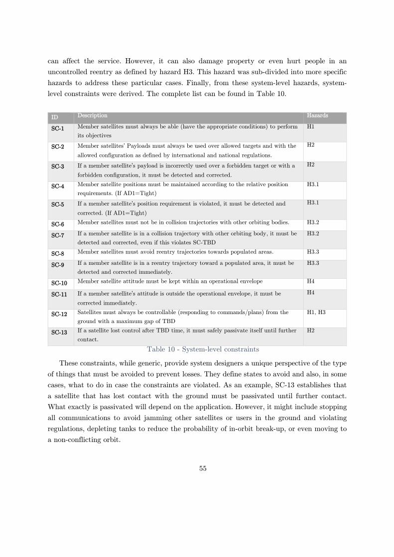
55
can affect the service. However, it can also damage property or even hurt people in an
uncontrolled reentry as defined by hazard H3. This hazard was sub-divided into more specific
hazards to address these particular cases. Finally, from these system-level hazards, system-
level constraints were derived. The complete list can be found in Table 10.
ID Description Hazards
SC-1 Member satellites must always be able (have the appropriate conditions) to perform
its objectives
H1
SC-2 Member satellites’ Payloads must always be used over allowed targets and with the
allowed configuration as defined by international and national regulations.
H2
SC-3 If a member satellite’s payload is incorrectly used over a forbidden target or with a
forbidden configuration, it must be detected and corrected.
H2
SC-4 Member satellite positions must be maintained according to the relative position
requirements. (If AD1=Tight)
H3.1
SC-5 If a member satellite’s position requirement is violated, it must be detected and
corrected. (If AD1=Tight)
H3.1
SC-6 Member satellites must not be in collision trajectories with other orbiting bodies. H3.2
SC-7 If a member satellite is in a collision trajectory with other orbiting body, it must be
detected and corrected, even if this violates SC-TBD
H3.2
SC-8 Member satellites must avoid reentry trajectories towards populated areas. H3.3
SC-9 If a member satellite is in a reentry trajectory toward a populated area, it must be
detected and corrected immediately.
H3.3
SC-10 Member satellite attitude must be kept within an operational envelope H4
SC-11 If a member satellite’s attitude is outside the operational envelope, it must be
corrected immediately.
H4
SC-12 Satellites must always be controllable (responding to commands/plans) from the
ground with a maximum gap of TBD
H1, H3
SC-13 If a satellite lost control after TBD time, it must safely passivate itself until further
contact.
H2
Table 10 - System-level constraints
These constraints, while generic, provide system designers a unique perspective of the type
of things that must be avoided to prevent losses. They define states to avoid and also, in some
cases, what to do in case the constraints are violated. As an example, SC-13 establishes that
a satellite that has lost contact with the ground must be passivated until further contact.
What exactly is passivated will depend on the application. However, it might include stopping
all communications to avoid jamming other satellites or users in the ground and violating
regulations, depleting tanks to reduce the probability of in-orbit break-up, or even moving to
a non-conflicting orbit.

56
In 2010, Intelsat announced that the satellite Galaxy-15 stopped responding to commands
due to an in-orbit anomaly leaving its transponders on (Allen, 2010). Moreover, the satellite,
in a regulated geosynchronous orbit, started to drift from its required position and could not
be corrected. This situation posed a risk of collision with other satellites as well as potential
jamming broadcasting communications on the ground over forbidden areas during eight
months before contact was regained, and the hazard was eliminated. During this time, most
of the safety constraints of Table 10 were also violated. Understanding the system losses and
hazards before the design has started can help eliminate these types of hazards.
Up this point in the analysis, goals, hazards, environmental and system-level constraints
were defined for any constellation disregarding the architecture implemented. The next section
presents the analysis of the selected architectures following the STPA methodology.
4.5. Architecture A1
Architecture A1 represents the most basic possible architecture in terms of Level of
Automation. In contrast to the manual direct control that might be possible in an airplane or
an industrial process, absolute attitude manual control by controlling each actuator is usually
unpractical. While it might be possible to control, for example, each thruster or reaction wheel
on a satellite to change its attitude, the complexity of doing it in a three-dimensional space
with orbital dynamics considerations make it impracticable. Hence, these low-level tasks are
performed by automated controllers within each satellite of the constellation.
Higher-level per satellite operations and all constellation's concerns are entirely managed
and controlled by the mission operations organization. In other words, the satellites are
unaware of the other satellites in the constellation. In the following sections, the resulting
control structure of this concept, along with the unsafe control actions and causal scenarios,
are presented, followed by an analysis of the emergent properties.
4.5.1. Control structure
Architecture A1’s conceptual control structure is depicted in Figure 16. As in any control
structure used in STAMP based analysis, the vertical axis represents authority while the
horizontal axis is information flow not directly related to control actions, but needed.
A color code was used to represent characteristics of the elements of the control structure.
Green controllers are human controllers and might be only one or more than one person. If a
box represents more than one human, an internal coordination process is assumed, generating
a unique mental model and control action.

57
In contrast, yellow controllers are automated controllers implemented by any type of
hardware and software combination. In the case of feedback and control lines, black lines
represent classical control, feedback, and information flow, as in any STAMP-based analysis.
While only one satellite is fully detailed in the control structure, it is essential to note that
all the satellites are considered. This multiplicity is represented by the dotted box surrounding
each satellite and then replicated as Satellite 1, Satellite 2, Satellite N. To clearly show the
implications of this difference, orange lines were used when the control action, feedback or
information flow goes from or to all the satellites of the constellation. This is the assumption
used in this first architecture for all the data between mission operations and the satellites.
In addition, dashed lines represent information that is used for health monitoring activities
and not direct control of the process.
Finally, nowadays, all the communications between satellites and ground are implemented
using digital communications and data corruption is rare. If a message arrives corrupted, it is
detected and discarded, so an improper execution of a command is usually just a delay or a
lost transmission and not a corruption of it.
From the control structure, it can be seen that a significant level of detail was included
inside each satellite. While this detail might have been abstracted too, including details such
as the arm/disarm propulsion commands, it helps to understand the number of commands,
sequencing, and coordination needed to operate the constellation. Many other controllers were
omitted because they are out of scope, for example, a thermal controller or a power controller.
They can probably also command the propulsion, attitude, and payload subsystems if they
need to in an emergency.
To conclude, training, operation procedures are not included for simplicity as information
flow to the human controllers, but it should be assumed they exist. The rest of this section
describes each of the controllers in the diagram, its responsibilities, and algorithms.

58
Figure 16 - A1 conceptual control structure
4.5.1.1. Controlled process
From a single satellite perspective, the three controlled processes are the orbit, the attitude,
and the payload. If satellites are correctly located and controlled, from a constellation
perspective, then the aggregation of all the individual satellite services will provide the
constellation service as a whole. Of course, this combination is not entirely linear, and the
constellation service is an emergent property of the system.
,
.
.

59
The launch of the member satellite defines the initial state of the orbit. Once in orbit, it is
affected by perturbations of the space environment like the atmospheric drag, the non-
uniformity of the Earth's gravity field, and the presence of other massive bodies of the solar
system. To compensate for these perturbations and to perform other orbital operations, a
propulsion system controls the velocity of the member satellites by generating a force in the
form of thrust.
Torque actuators control the attitude of the member satellites. As with the velocity, the
attitude is also perturbed by the space environment, in particular atmospheric drag, magnetic
forces, and solar radiation pressure.
Finally, the payload process of the member satellites is included. No details are provided
because they depend heavily on the application. It might be an imaging device, a radar, a
radio transceiver, a signal generator, or other any specific instrument. How to control these is
left to the designer of the constellation.
4.5.1.2. Propulsion controller
The propulsion subsystem is in charge of producing thrust to change the velocity of the
satellite, which, in effect, alters the orbit. Thrust is generated by expelling propellant in a
particular orientation, and in some applications, the thrust orientation can slightly be defined
by the propulsion subsystem. Nevertheless, a particular attitude is required to point the force
coarsely. In most cases, propulsion systems are open-loop control systems in terms of
controlling the orbit of a satellite, and they only control specific parameters of the propulsion
hardware. This assumption is depicted by the absence of a sensor of velocity. The close loop
control of the orbit is often in outer loops without knowledge of the propulsion subsystem.
The propulsion controller implements the lowest level of automation related to controlling
the high-speed loops of the propulsion elements through an automated controller. The primary
responsibilities are to:
- Produce thrust according to the requested commands by controlling, for example, the
pressure of tanks, the amount of electrical power to a Hall effect thruster, and opening
or closing of valves.
- Oversee the safety of the elements of the subsystem (not over-pressurizing a tank for
example)
Operating modes
The propulsion controller implements three different modes: a nominal mode in which
propulsion maneuvers can be done, a fault-handling mode, and a shutdown or software update
mode. In this last mode, the controller is unavailable for any operation and only responds to
software update related commands. Within the nominal mode, disarmed, armed, thrusting

60
sub-modes are implemented to allow system preparation and to prevent unintended thrusting.
The arm modes prepare the subsystem for subsequent propulsion commands. In general, an
arm mode might be needed by different propulsion systems to pressurize tanks, purge lines,
and heat elements. The system can stay in this mode forever (except when there is a
malfunction detected in which the controller goes to fault-handling mode), but being on an
armed mode requires more power than being in a disarmed mode.
These modes and their transitions can be seen in Figure 17. Transitions in italics are
automatic transitions that the controller can issue. All the remaining transitions are
commanded externally.
Figure 17 - Propulsion subsystem operating modes
Interface
When the system is armed, it can accept and execute “Propulsion commands.” If the system
is disarmed, it should not respond to a “Propulsion command.” Depending on the system, it
might take time for the system to be armed after a mode change is requested.
The disarm command does the opposite. It disables any thrust being generated and puts
the subsystem into a safe state that can be held forever.
The propulsion command is a combination of thrust levels in the appropriate units
(depending on the thruster design and configuration) and a thrust direction if applicable. Once
triggered, the controller stays in thrusting mode until a thrust command cancels it with 0

61
thrust (goes back to armed), the system mode is set to disarm, or an internal malfunction is
detected. As with any other commands, they can be sent as a real-time command or as time-
deferred or location-deferred command.
There is only one display mode in which the automated controller provides to its controller
the current Operating mode, thrust (estimated or measured), and alarms telemetry. Also, raw
data from the actuator’s sensors are provided for health monitoring.
Control algorithm
The control algorithm is in charge of two main functions: generate control actions to control
the actuator and maintain accurate information (models) about the state of the controlled
process and external system components and environment that can impact the generation of
control actions.
In this case, the propulsion system does not have a direct model of the controlled process
(the velocity of the satellite), as explained before. However, it has a model of the actuators as
a sub-controlled process. It might also have information about orientation in each satellite
from manufacturing and calibration and pre-loaded information about the amount of
propellant that has to be updated.
The controller does maintain the model of the operational mode. In this case, only the
automation operating mode is considered, according to the state diagram in Figure 17. The
controlled process mode (the satellite mode described in Figure 15) is not known or considered
by the subsystem. Because there is only one controller —mission operations— there is no model
of supervisory mode to track. As explained in the interface section, there is also only one
display mode to consider.
Other possible models like the model of the human controller and model of other controllers
are not applicable because the system does not have any other controller or the human
controller is not monitored.
4.5.1.3. Attitude controller
The attitude subsystem is in charge of controlling the orientation of the satellite with
respect to a reference frame in line with a specified setpoint and to determine the current
satellite position and velocity (ephemeris). In general, attitude subsystems combine
measurements of the position of the sun, the stars, the magnetic field, angular velocity, and
position and velocity in orbit to determine its current orientation and position with respect to
a reference frame. All this is abstracted in the “Sensors” block.

62
Control actions employing torque (produced by momentum exchange devices like reaction
wheels, CMGs or magnetic rods, or off-axis applied forces by thrusters) are used to control the
attitude in order to follow the commanded pointing mode and setpoint. As with sensors, they
are all abstracted in the “actuators” block.
Pointing modes allow different types of profiles and are used for different tasks in any of
the satellite modes, for example, pointing the solar panels to the sun on idling, looking down
to acquire science measurements, or following a moving target on the ground.
The attitude controller implements the lowest level of automation related to control the
high-speed loops of the actuators through an automated controller. The primary
responsibilities are:
- Change or maintain the satellite attitude according to the requested setpoint and mode.
- Oversee the safety of the elements of the subsystem
Operating modes
The specific modes will depend on the final design and concept of operations of the
constellation and the satellite. However, it can be assumed that the system has the primary
nominal, shut-down, and fault-handling modes, as in the case of the propulsion subsystem.
Interface
The only command considered in the analysis is an “attitude command” that is a
combination of a pointing mode and a setpoint. The system assumes that the mode and the
setpoint should be maintained unless a new command overrides it or an internal malfunction
is detected.
Like any other commands, they can be sent as a real-time command or a time-delayed
command. Like any other commands, they can be sent as a real-time command or as a time-
deferred or location-deferred command.
There is only one display mode in which the automated controller provides to the supervisor
the current operating mode, setpoint, and alarms telemetry. Also, raw data from the actuators
and sensors are provided.
Control algorithm
The control algorithm maintains a model of the controlled process contains information
about the current attitude, angular velocity, position, and velocity with feedback from sensors.
Also, the control algorithm requires information on the orientation and position of these sensors
and actuators in the satellite as well as the inertia tensor of the satellite. The control algorithm
might also have perturbation models to correct in advance. This information is loaded on each
satellite before launch and can be updated later on during operations.

63
The controller also maintains the model of the operational mode. In this case, only the
automation operating mode is considered, according to the three states defined previously.
The controlled process mode (the satellite mode described in Figure 15) is not known or
considered by the subsystem. Because there is only one controller, mission operations, there is
no model of supervisory mode to track. As explained in the interface section, there is also only
one display mode to consider, so no tracking of it is done either.
Other possible models like the model of the human controller and model of other controllers
are not applicable because the system does not have any other controller or the human
controller is not monitored.
4.5.1.4. Payload controller
The payload controller is in charge of controlling how the payload is used according to ad-
hoc commands that depend on the application. It might also control the payload pointing if
necessary employing mechanical movement or electronic steering, for example. Usually,
however, payloads still need a coarse pointing provided by the entire satellite platform, which
will be achieved through the attitude subsystem.
Operating modes
The specific modes will depend on the final design and concept of operations of the
constellation and the satellite. However, it can be assumed that the system has the primary
nominal, shut-down, and fault-handling modes, as in the case of the propulsion subsystem.
Interface
As an example of things in the interface, “payload on” and “payload off” commands are
included that might apply to all different types of payload. Also, mode, alarms, and ad-hoc
information are provided to the controller of the subsystem.
Control algorithm
Because the control algorithm is entirely dependent on the application and the payload,
the control algorithm is not analyzed.
4.5.1.5. Mission operations
Mission operations is a relatively complex organization in charge of the operations of the
satellite constellation. This organization is responsible for the proper execution of the company

64
goals while maintaining a healthy and reliable constellation. For this analysis, it was modeled
as four different controllers. Each of these controllers is described below.
4.5.1.6. Satellite controllers
The satellite controllers are the contact between the ground and the member satellites, and
they directly command the satellites through terminals or operations software. They are also
known in the industry as satellite operators or console operators. Their responsibilities are
divided into operation tasks and monitoring tasks as following:
- Operations:
o Apply the burn plans provided by Orbital dynamics team (by specializing each
burn plan into specific satellite commands)
o Apply the payload plans provided by the Payload team (by specializing each
mission plan into specific satellite commands)
o Apply the defined maintenance and operations requested by other teams
o Monitor that the automation is performing as expected
o Monitor satellite attitude for unsafe (out of range) operations
- Health monitoring:
o Monitor the health of the satellites (and other elements of the system not
included in this conceptual diagram) and resolve conflicts.
o Provide troubleshooting and anomaly resolution
As seen in the control structure in Figure 16, they have to command every low-level detail
of each subsystem such as arming/disarming turning on and of the payloads and coordinating
those actions with the correct attitude. Depending on the application, providing this control
might be a very demanding job.
The decision-making process is done by using the information in the mental models (which
they have to maintain) plus the goals, training, written procedures, and experience. Satellite
controllers are also affected by external controllers and external factors like time pressure and
company objectives. For each satellite, satellite controllers have to maintain four different
mental models:
- Model of automation: status and mode of each controller on each satellite (for the
attitude controller, the propulsion controller, and the payload controller).
- Model of the controlled process: current orbit, attitude, and payload status of each
satellite. Moreover, they also have to maintain the mode in which each satellite is
(Figure 15). It is important to remember that this mode is only in the controller’s mind
(or tools) for this architecture.

65
- Model of the environment: what might affect the satellite operations like the ground
station and connection issues, for example.
To update these models, satellite controllers use information and feedback provided by the
satellites and other components of the system. However, in order to assess each satellite health,
satellite controllers also monitor the process directly by using direct information from the
sensors and some of the actuators of the satellite. This multiplicity of sources can lead to
potential. For example, satellite controllers can check the attitude quaternions telemetry or
the status telemetry to see if an attitude is correct or not. This information can be misleading
or confusing and a potential source of bad decisions.
Moreover, satellite controllers coordinate with the payload and ODT to deconflict potential
overlaps of operations that cannot happen. Coordination problems, however, might still create
overlapping plans for a satellite. In order to deconflict, company-level priorities should be
defined and communicated to these teams. Finally, if maintenance operations are needed,
satellite controllers have full control over the satellite subsystems, so they only have to
coordinate with ODT and Payload to do it.
4.5.1.7. Orbital dynamics team
The orbital dynamics team (ODT) is the team responsible for controlling the orbit of the
satellite in line with mission management requirements and with system operational
requirements. Specifically, they are responsible for:
- Defining the best constellation shape concerning the coverage requirements provided.
- Maintaining the satellite position in the defined constellation shape by monitoring the
current state and issuing burn plans. (If AD1=Tight)
- Avoiding in-orbit collisions
- Decommissioning of satellites, when instructed by mission operations.
In order to support their decision-making process, the orbital dynamics team has to maintain
different mental models.
- Model of the controlled process: Member satellite current orbit and information about
the maneuvering capabilities of each satellite as well as state variables like the
remaining propellant, for example.
- Model of automation: current status of the maneuver execution by satellite controllers.
- Model of the environment: Non-member satellites orbit that can be a hazard for the
member satellites, perturbances that are affecting or will affect the current constellation
shape (space weather)

66
- Model of other controllers: Because the satellite attitude is shared with the payload
operations, ODT needs to maintain a model of what is the Payload team is doing in
order not to overlap the operations.
To update these models, the ODT use position and velocity information (ephemeris)
provided by the satellites as well as information from third-party sources if needed. They also
use these third-party sources for potential collision detections, and they might also implement
their algorithms for determining how and when to maneuver for relative satellite position and
collision avoidance activities.
Some organizations do not have the capabilities to predict collisions and to perform
maneuvers and rely only on third-party sources. Others use both. Appropriate prioritization
and coordination of information are needed to avoid potential hazards. The ODT also uses the
information provided by mission management about the configuration and capacity of each
satellite. Status of burns is provided by the satellite controllers to update their mental models
about the maneuvers and the propellant used, for example.
To control the satellites, the ODT communicates a “burn plan” for each of the satellites to
the satellite controllers. A burn plan is specified as a series of burns with a defined thrust and
direction for a specific duration. Also, specific timing and attitude for each burn are included.
An example of a burn plan is provided in Table 11. By design, the ODT does not need to
know specifics about how to operate the propulsion system of each satellites, which is done by
the satellite controllers, but they need to know what each satellite is capable of doing. Then,
a burn plan is specified in generic terms applicable to any satellite, and it is the responsibility
of the mission operators to translate this into appropriate commands for each specific satellite
in the constellation.
Satellite Time Attitude Thrust
angle
Thrust Duration
Satellite-1 2020-10-01 10:30:40 UTC (0, 90, 90) (0,0,0) 100mN 60s
Satellite-1 2020-10-01 12:05:40 UTC (0, 90 ,90) (0,0,0) 100mN 60s
Satellite-1 2020-10-01 15:10:40 UTC (0, 270, 90) (0,0,0) 100mN 60s
Satellite-1 2020-10-01 16:45:40 UTC (0, 270, 90) (0,0,0) 100mN 60s
Table 11 - Burn plane example
4.5.1.8. Payload team
The payload team is in charge of planning the operations of the payload in line with the
mission goals provided by mission management. Depending on the application, this
responsibility might be defining what sensor or transmitter to use, how to configure

67
transponders, or when and how to acquire images over a specific area of interest, for example.
Independent of what they need to do, they communicate this in a payload plan for each satellite
to the satellite controllers. A payload plan consists of:
- Series of payload ad-hoc commands with a specific time
- Attitude for each payload operation
In order to support their decision-making process, they have to maintain different mental
models.
- Model of the controlled process: what is each satellite payload doing, where is each
satellite of the constellation, what is each satellite capable of,
- Model of automation: current status of the payload operation executed by the satellite
controllers.
- Model of other controllers: Because the satellite attitude is shared with the payload
operations, ODT needs to maintain a model of what the ODT is doing in order not to
overlap the operations.
To update these models, the payload team uses the information provided by the satellite
controllers about the execution of the plans as well as satellite configuration and capabilities
provided by the mission management.
4.5.1.9. Mission management
Mission management is responsible for the constellation operation in general. They define
what coverage they need and what mission goals they have based on the provided company
goals and client and users’ requests (if any). Because coverage changes are very costly, slow,
and sometimes out of reach, they have to predict which coverage they will need before starting
operations. To do so, they need to coordinate with the orbital dynamics and payload teams to
select and configure the proper launch that will provide the initial ephemeris to the satellites.
This responsibility is not considered in the model and is left for future work. Mission
management controls the satellite constellation by issuing coverage requirements and mission
goals to the orbital dynamics team and the payload team, respectively.
In order to support their decision-making process, mission management has to maintain
different mental models. They have a model of the controlled process, which is the satellite
constellation as a whole, that is updated by information provided by the orbital dynamics
team, the payload team, and the satellite controllers. This information is related to the current
coverage capacity and the operational status of the satellites in the constellation.

68
4.5.2. Unsafe control actions
Using the control structure and safety constraints defined in the previous section, unsafe
control actions were identified. Table 12 presents a fragment of the UCA table for this
architecture. Each UCA is labeled as the UCA-Architecture-ID for further reference. The
complete UCA table can be found in Appendix C. It is important to notice that STPA is a
qualitative tool, and the number of control actions does not represent a proxy for the
probability of occurrence or how risky a control action is.
Control
action
Not providing Providing Too early, too late,
out of order
Stopped too soon,
applied too long
Thrust UCA-A1.1: The
propulsion controller
does not generate
thrust when it is
armed and is
commanded to do it
[H3]
UCA-A1.2: The
propulsion controller
generates thrust in an
incorrect direction or
magnitude when it is
armed and
commanded to do it
[H3]
UCA-A1.3: The
propulsion controller
generates thrust when
it is armed, but it was
not commanded to do
it [H3]
UCA-A1.4: The
propulsion controller
generates thrust with
more than TBD of
delay when it is
armed and
commanded to do it.
[H3]
UCA-A1.5: The
propulsion controller
stops generating
thrust when there is
no alarm, it was
commanded to, and
the system is armed.
[H3]
UCA-A1.6: The
propulsion controller
keeps generating
thrust after being
commanded to stop
by a thrust=0 or
disarm command. [H3]
Torque UCA-A1.7: The
attitude controller
does not provide
torque when it is
needed to maintain or
follow a setpoint. [H1,
H3, H2, H4]
UCA-A1.8: The
attitude controller
provides a torque in
the wrong direction or
with the wrong
magnitude when a
torque is needed to
maintain or follow a
setpoint. [H1, H3, H2,
H4]
UCA-A1.9: The
attitude control
subsystem provides a
torque when it is not
needed [H1, H2, H3,
H4]
UCA-A1.10: The
attitude controller
provides delayed
torques when is
needed to maintain or
follow a setpoint. [H1,
H3, H2, H4]
UCA-A1.11: The
attitude controller
stops applying torque
too soon when still
needed to maintain or
follow a setpoint. [H1,
H3, H2, H4]
UCA-A1.12: The
attitude controller
keeps applying torque
when not needed
anymore. [H1, H3, H2,
H4]
Arm UCA-A1.13: Satellite
controllers do not
provide an arm
command before a
propulsion command
when performing
orbital maneuvers
(because the satellite
is in an inadequate
orbit) [H3]
N/A UCA-A1.14: Mission
operations provide an
arm command too
early (TBD minutes)
before an orbital
maneuver (resulting in
a waste of energy that
prevents the payload
from operating) [H1]
N/A

69
Control
action
Not providing Providing Too early, too late,
out of order
Stopped too soon,
applied too long
UCA.A1. 15: Satellite
controllers provide an
arm command too
late to perform an
orbital maneuver
when a satellite is in
an inadequate orbit.
[H3]
Disarm UCA-A1.16: Satellite
controllers do not
provide a disarm
command after
concluding orbital
maneuvers (resulting
in a waste of energy
that prevents the
payload from
operating) [H1]
UCA-A1.17: Satellite
controllers provide a
disarm command
when the system is
performing as
expected and is doing
orbital maneuvers
(resulting in
incomplete
maneuvers) [H3]
UCA-A1.18: Satellite
controllers provide a
disarm too late after
concluding orbital
maneuvers (resulting
in a waste of energy
that prevents the
payload from
operating) [H1]
N/A
Attitude
command
UCA-A1.26: Satellite
controllers do not
provide an attitude
command when
necessary for a
payload or maneuver
operation [H1, H3]
UCA-A1.27: Satellite
controllers do not
provide a change
attitude mode when
the satellite is in an
unsafe attitude (i.e.,
sun on a payload, no
sun on solar panels,
etc.) [H4]
UCA-A1.28: Satellite
controllers provide an
attitude command
with the incorrect
mode or setpoint
when it is needed by a
payload or a
maneuver operation
[H1, H2, H3, H4]
UCA-A1.29: Satellite
controllers provide an
attitude command
with a forbidden
setpoint and mode
when doing
maintenance
operations. [H4]
UCA-A1.30: Satellite
controllers provide an
attitude change when
a satellite does not
need it. [H1, H2, H3,
H4]
UCA-A1.31: Satellite
controllers provide an
attitude change for a
payload operation
when the satellite is
doing a maneuver
operation or vice-
versa. [H1, H3]
UCA-A1.32: Satellite
controllers provide an
attitude command too
late when it is
required by a payload
or maneuver operation
[H1, H2, H3]
N/A
Table 12 - A1 UCA Table summary

70
As can be seen in the second column, not providing a control action can be unsafe. For
example, Arm and Payload on commands are preparatory commands. Not providing them will
affect future propulsion or payload operations. At a higher level, not providing an attitude
command will spoil any type of payload or maneuver operation or will prevent a satellite in
an unsafe attitude to correct its orientation. At the highest level, not providing a burn plan
will leave or put a satellite in an inadequate orbit that can flaw the mission operations, create
an in-orbit collision, or damage people or assets in the ground during a reentry. Likewise, not
providing a payload plan will leave the satellites idle not achieving mission goals.
Providing control actions can be unsafe too. Since having the correct attitude is needed for
orbital maneuvers and payload operations, it can be unsafe to provide an attitude command
for a payload when the satellite is doing an orbital maneuver, for example. These coordination
problems should be resolved in the ground in this architecture because the level of automation
on the satellite is minimum. Still, flawed coordination can provide scenarios for this UCA to
happen, a problem also known as “shared resource coordination” (K. E. Johnson, 2017).
While some of these UCAs might be avoided if envelope protection systems or coordination
is included in the satellites, that would disrupt the level of automation that characterizes this
architecture.
Finally, the only control actions that potentially involve duration related unsafe control
(stopped too soon or applied too long) are those analog controls actions found in the lower
level of the control loop: Thrust, and Torque. This type of unsafe control action does not apply
to the rest of the control actions.
From the UCAs found for this architecture, it was possible to derive component-level
constraints that, if enforced, would eliminate or reduce the likelihood of these unsafe control
actions. As examples, the constraints derived from the UCAs included above are provided in
Table 13. The complete component-level constraints list can be found in Appendix C.

71
UCA Derived Constraints
UCA-A1.1 SC-1: The propulsion controller must always generate thrust when it is armed and commanded
to do it.
UCA-A1.6 SC-6: The propulsion controller must not generate thrust after being commanded to stop by a
thrust=0 command or disarmed.
UCA-A1.8 SC-8: The attitude controller must provide torque in the correct direction and magnitude
necessary to control the attitude of the satellite.
UCA-A1.11 SC-11: The attitude controller must provide torque for all the time needed to maintain or follow
a setpoint.
UCA-A1.22 SC-22: Propulsion commands must be sent only when the satellite has acquired the necessary
attitude for the burn.
UCA-A1.24 SC-24: Propulsion commands must not be provided when a satellite is doing a payload
operation.
UCA-A1.31 SC-32: Attitude commands for an operation must not be provided during another operation.
UCA-A1.33 SC-34: A payload on command must be provided before any ad-hoc command is sent to the
payload.
UCA-A1.35 SC-37: A payload on command must not be provided when the satellite has a forbidden
attitude.
SC-38: Forbidden attitudes information must be provided before starting operations.
UCA-A1.39 SC-42: A burn plan must always be provided when a satellite is in a collision trajectory to avoid
it.
Table 13 - A1 Component level constraints
These component-level constraints can be used to drive the requirement and specification
definition for the different component levels in the following phases of the design, and they
might also be useful for defining the component level verification and validation strategy. They
provide a functional perspective that can be easily missed in the detailed design and
manufacturing phases.
4.5.3. Causal scenarios
For each UCA found for this architecture, it was possible to derive causal scenarios that
might lead to hazards. Also, dozens of scenarios were found that were not related to UCAs
but were related to the incorrect communication or execution of control actions. Both types of
scenarios are usually application-specific scenarios that depend strongly on the implementation
of the satellite constellation. In addition, more generic scenarios that identify potential causal
factors were created. The complete scenarios for this architecture can be found in Appendix
A. As an example, from UCA-A1.1, the following scenarios were found:
- Scenario 1: The Propulsion subsystem physical controller goes into fault-handling or
shut-down when a propulsion command is issued due to a physical controller failure,

72
causing the thrust not to be generated. As a result, the maneuver is flawed, and the
satellite ends in an inadequate orbit. [H3]
- Scenario 4: The propulsion subsystem controller is armed and is commanded to
generate thrust. The propulsion subsystem does not generate thrust because the
information provided during the launch preparation of the satellite incorrectly indicates
that tanks are empty. As a result, no thrust is generated, and the orbital maneuver is
flawed, and the satellite ends in an inadequate orbit. [H3]
- Scenario 6: The propulsion subsystem controller is armed and is commanded to
generate thrust by a propulsion command. The actuators are behaving as expected,
but the propulsion subsystem does not generate thrust because it believes there is a
problem with the actuators and disarms the subsystem. This flawed process model will
occur if correct feedback (i.e., confirmation of a valve opening) is received with delay
or never received and can happen if any of the following occur: there is a wiring or
communication problem between a sensor and the controller, a sensor fails and does
not report any data, or there is a problem reading a sensor data in the controller (i.e.,
the controller is busy with another higher-level task. As a result, no thrust is generated,
and the orbital maneuver is flawed, and the satellite ends in an inadequate orbit. [H3]
These examples provide typical causal factors found in the analysis. The first scenario
represents a physical failure, which is the type of scenario that can be found with FMEA or
FTA tools too. However, the remaining scenarios are related to missing or incorrect information
provided to the controller during a data load or during normal operations through sensors.
This type of missing or incorrect information incorrectly updates the models in the controller
that then leads to unsafe control actions. Also, scenarios in which safe control action were
provided but were not executed or were improperly executed were found. As an example:
- Scenario 179: Payload issues a mission plan, but the plan does not arrive at the satellite
controllers due to a communication problem. As a result, the satellite is unable to
perform its objectives [H1].
- Scenario 180: Payload issues a mission plan, but the plan is ignored or received later
because satellite controllers are busy doing other tasks. As a result, the satellite is
unable to perform its objectives [H1]
In these last two scenarios, interactions between human controllers are considered. The
communication problem described in scenario 179 might be a human communication problem
or a software communication problem. Scenario 180 shows how a busy controller may lead to
a potential hazard too. That is why correctly sizing the number of satellites per controller in

73
this architecture is critical. Confusion, overloading, coordination problems are all different
causal factors that can be found by the analysis.
Other types of scenarios involve human controllers. For example, when conducting orbital
maneuvers, satellite controllers need to coordinate the satellite attitude with the burns. Two
example scenarios that can lead to hazards are.
- Scenario 60: Mission operations needs to perform orbital maneuvers on a satellite to
correct its orbit. The system is armed. A wrong direction or magnitude is sent to the
propulsion controller because the satellite controller inputs a typo or copy and pastes
an incorrect value from a burn plan. As a result, the maneuver operation is flawed, and
the satellite stays in an inadequate orbit [H3]
- Scenario 61: A member satellite is transitioning to the correct attitude for an orbital
maneuver but has not arrived there yet. Satellite controllers provide a propulsion
command because they incorrectly believe the satellite has the correct attitude. This
flawed process model will occur if the attitude subsystem state (indicating a locked
attitude) is not received or ignored and can happen if any of the following occur:
o The controller ignores the state telemetry because it is usually very fast to lock
the attitude.
o The “transitioning” concept state is not implemented in the subsystem, and the
controllers are incorrectly trained to derive it from the direct attitude telemetry
(which might be confusing).
o The state is sensed but not transmitted in the telemetry, and other telemetry
makes the satellite controller believe it is locked.
o The state is received in the ground but is not displayed in the operator console,
and other telemetry makes him believe it is locked.
As a result, a maneuver is done unproperly, and the satellite ends in an inadequate
orbit [H3]
These two scenarios are good examples of the complexity of the tasks that human operators
need to do in this architecture. Similar scenarios are provided for payload operations as well.
Time-deferred commands (when AD2 is intermittent) might aid in the preparation and testing
of the control actions as well as to help identify missing feedback in advance.
In total, 181 causal scenarios were found related to unsafe control actions and improper or
no execution of control actions. A summary of the different causal factors found for this
architecture is presented in Figure 18 using the causal factors illustrated in Figure 11 with the
distinction that inappropriate decisions were separated between those taken by humans and
those taken by an automated controller.

74
Figure 18 - A1: Summary of causal factors
It is possible to see that most of the causal factors are related to improper decisions taken
by human controllers. These improper decisions include flawed operating procedures, flawed
training, mode confusion, and also controllers being too busy and ignoring critical information
and not taking corrective actions. There is also a significant number of causal factors related
to errors of commission, due to the complex tasks of translating and configuring commands
manually as well as those related to confusion. It was also found to be very likely for human
controllers to incorrectly interpret feedback due to the heterogeneous and large number of
systems being monitored. Moreover, it was found that because most actions are coordinated
and controlled by ground operations, communication issues with the satellites (delays or lost
transmissions) might also create inadequate feedback or inadequate execution of control
actions. These issues might worsen if the connectivity between satellites and ground is
intermittent (AD2).
4.5.4. Architecture conclusions
Architecture A1 represents the lowest possible level of automation that can be found in
satellite constellations. Only very low-level tasks are automated on each satellite, and the
satellite operations management is done entirely by human controllers within the mission
operations team. This architecture suggests a relatively simple design at very high operational
costs.

75
It is possible to assess the system scalability by analyzing the control structure and the
human controller responsibilities. Satellite controllers have two main tasks in this architecture:
health monitoring and mission operations. In order to perform correct mission operations, they
have to maintain multiple mental models of each satellite in order to safely and reliably operate
the constellation. Most of the control action generation requires specific sequences and timing
constraints that make these tasks even more challenging. Also, control action generation
requires training and concentration. Satellite controllers have two direct controllers, Orbital
Dynamics, and Payload teams, apart from potential external requests from the organization,
and they have to coordinate their requests.
Concerning health monitoring, satellite controllers are also responsible for monitoring raw
data coming from sensors and actuators to ensure that the satellites are performing as expected
or request maintenance or troubleshooting by other teams. Since these tasks should be
performed for every satellite in the constellation, the number of satellite controllers needed will
be proportional to the constellation size to ensure they have enough time to perform all their
duties with each of the satellites of the constellation without jeopardizing the operation. Also,
a high level of expertise is required to address all these duties.
Similarly, the Orbital dynamics team has to control and monitor each satellite of the fleet
to ensure that they are in the correct position and that they are not on collision trajectories.
Then, they have to issue burn plans for each satellite in the constellation. While this
responsibility is less time demanding than the satellite controllers, the amount of work will
still scale with the constellation size. The expertise required will also be very high.
Likewise, the payload team has to issue payload plans and monitor the performance of
each satellite of the fleet. Depending on the application, this might represent a very low or a
very high workload. For example, in a communications application, usually, payloads are
configured at the beginning, and additional configuration or plans are provided relatively
separate in time responding to troubleshooting or changes of service. Instead, in earth
observation application, the tasking on the satellites can be done in real-time and depending
on the client's requests. The skill levels required will also vary with the application, but specific
knowledge of the payload hardware and the overall satellite technology is usually required.
From the analysis of the causal scenarios and their related hazards, it is possible to evaluate
the safety and reliability aspects of this architecture. As seen, most of the scenarios are related
to the inappropriate decisions of human controllers, which is a direct consequence of the low
or nonexistent level of automation of this architecture. These inappropriate decisions are
consequences of flawed operating procedures, lack of training, misleading or ambiguous
information provided to human controllers, bad interface design, and ultimately in how
overloaded the controllers are.

76
Apart from the inappropriate decisions, the remaining two major hazard causal factors
identified are related to inadequate communication of control actions and feedback. These
causal factors can be divided into three different types. The first type encompasses in-ground
communication problems between different teams within the mission operation team.
Coordination and resource sharing were found as a significant contributing factor as well as
human communication problems caused by overwhelmed controllers. The second group
corresponds to the communication between the ground and space. Since satellites are entirely
controlled from the ground, any disruption in the communication is a potential scenario for
safety or reliability concerns. Finally, intra-satellite communication problems are also a
potential causal factor for safety and reliability problems.
Inappropriate decisions related to automation are relatively low compared to human
decision making. Such inappropriate decisions reflect specification and implementation flaws
in the propulsion, attitude, and payload controllers. Likewise, physical controller failure,
actuator, and sensor problems are also a potential causal factor for safety and reliability.
Traditional reliability engineering techniques can address some of these issues.
Given that most of the scenarios for this architecture are related to human error, and
because human error is not random, designers and operators choosing an architecture like this
should focus their efforts on designing systems with human factors considerations in mind.
Also, the interconnection between satellites and ground was found critical, and designers and
operators should focus on maximizing the connection time between satellites and ground to
allow proper mental model updates. Finally, appropriate staffing levels (satellites per
controller) should be carefully analyzed and addressed for each particular application in order
to avoid controller overloading, which is the backbone of all the operations.
4.6. Architecture A2
Architecture A2 adds one level of automation on the satellites. In this case, an automated
controller, the On-Board controller (OBC), is responsible for controlling the propulsion,
attitude, and payload subsystems. The OBC now does most of the low-level tasks that were
performed by human operators such as arming and disarming the propulsion system or
coordinating the attitude mode in each operation. Health monitoring is still performed by
mission operations manually. Constellation level management is still done entirely by mission
operations.
4.6.1. Control structure
The control structure for this architecture is depicted in Figure 19. Unlike architecture A1,
this architecture adds the OBC between mission operations and the satellites’ subsystems. As

77
can be seen in the diagram, Propulsion, Attitude, and Payload subsystems are the same as in
A1, with the same interfaces and algorithms. The only difference now is that the supervisor of
these subsystems is now the OBC instead of mission operations. Orbital dynamics teams, the
Payload team, and the satellite controllers now interface with the OBC, and thus, their control
actions and responsibilities changed considerably. In the rest of this section, the new OBC is
described as well as how mission operations roles, responsibilities, and interfaces are changed.
The controllers and elements of the control structure that are identical to architecture A1 are
not included here to avoid duplication.

78
Figure 19 - A2 conceptual control structure
4.6.1.1. On-board controller
The on-board controller is in charge of commanding the subsystems of the satellite. One of
the most significant changes is that satellite operation mode is now controlled and maintained
by this new on-board controller. Its primary responsibilities are:
- Execution of orbital maneuvers as specified by a maneuvering plan, through controlling
the propulsion and attitude of the satellite.
,
.
.
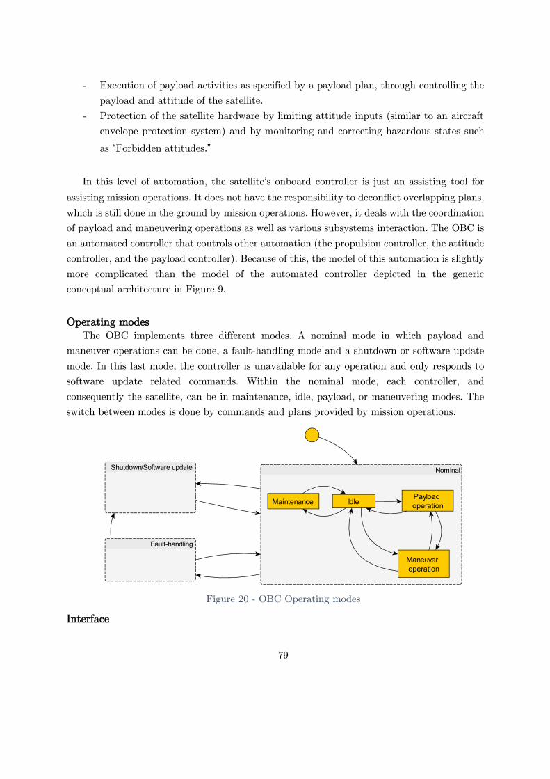
79
- Execution of payload activities as specified by a payload plan, through controlling the
payload and attitude of the satellite.
- Protection of the satellite hardware by limiting attitude inputs (similar to an aircraft
envelope protection system) and by monitoring and correcting hazardous states such
as “Forbidden attitudes.”
In this level of automation, the satellite’s onboard controller is just an assisting tool for
assisting mission operations. It does not have the responsibility to deconflict overlapping plans,
which is still done in the ground by mission operations. However, it deals with the coordination
of payload and maneuvering operations as well as various subsystems interaction. The OBC is
an automated controller that controls other automation (the propulsion controller, the attitude
controller, and the payload controller). Because of this, the model of this automation is slightly
more complicated than the model of the automated controller depicted in the generic
conceptual architecture in Figure 9.
Operating modes
The OBC implements three different modes. A nominal mode in which payload and
maneuver operations can be done, a fault-handling mode and a shutdown or software update
mode. In this last mode, the controller is unavailable for any operation and only responds to
software update related commands. Within the nominal mode, each controller, and
consequently the satellite, can be in maintenance, idle, payload, or maneuvering modes. The
switch between modes is done by commands and plans provided by mission operations.
Figure 20 - OBC Operating modes
Interface

80
A maneuver plan consists of maneuvers and the required parameters. Like any other plan,
maneuver plans can be real-time or time deferred. Due to the specificity of a maneuver, most
maneuvers are time deferred. Maneuvers are a combination of burns at different points in the
orbit along with specific angles and durations. There are widespread maneuvers, like a
Hohmann transfer, that changes the altitude of an orbit with two burns, but any specific
maneuver can be implemented depending on the applications. GEO satellite maneuvers will
probably be different from those for a LEO satellite constellation. Following the same example
that was proposed for A1, a more straightforward interface and more abstract can be
communicated to the OBC to perform a phasing maneuver.
- Maneuver 1:
o maneuver-type=Hohmann, delta-semimajor=+10Km
- Maneuver 2
o maneuver-type=Hohmann, delta-semimajor=-10Km
The OBC then coordinates and provides all the low-level commands that are needed to
perform the maneuver, as was done previously by satellite controllers.
Payload plans are still the same as in architecture A1, with the difference that they are
directly provided to the OBC without the intervention of the satellite controllers.
Finally, because the satellite controllers are not in direct control of the subsystems any
more, it was necessary to add a maintenance mode command to change the mode of the
satellite to allow manual maintenance to be provided by a satellite controller. In this mode,
satellite controllers regain access to low-level functionality of the satellite and propulsion, and
payload maneuvers are forbidden.
Control algorithm
The OBC control algorithm can be divided into two principal control algorithms. One for
controlling the satellite orbit by performing orbital maneuvers and one for controlling the use
of the satellite payload. These two control algorithms require different types of models, with
the only overlap in the models related to the attitude that is needed for both control actions.
And, as with the other automated controllers, each control algorithm is divided into the control
action generation and the update of the models.
For controlling the satellite maneuver operations, the OBC has to maintain a model of the
controlled process, which in this case is the propulsion subsystem status and actuators status,
the current orbit and the satellite attitude as well as configuration information like mass,
propellant, and inertia moments. This update is done by sensor feedback from the propulsion
and attitude controllers, respectively, and by information provided on ground previously to
launch or updated during operations. The controller also has to maintain the status of the
operational modes of the attitude and propulsion controllers. Then, with the updated models,

81
it has to provide the appropriate control actions for the propulsion controller (arm, disarm,
and propulsion commands) and the attitude controller (attitude command).
Similarly, for controlling the satellite payload operations, the OBC has to maintain a model
of the controlled process, which in this case is the satellite attitude and payload status also
updated by sensors and indirect data loads. The controller also has to maintain the status of
the operational modes of the attitude and payload controllers. With the updated models, it
has to provide the appropriate control actions for the attitude controller (attitude commands)
and payload controllers (payload on, payload off, and ad-hoc commands).
Moreover, the OBC now has the responsibility to keep track and implement the operational
satellite mode presented in Figure 20. This current mode can be changed in several ways. The
satellite controller can request the OBC to change to maintenance mode if needed. Also, the
payload and maneuver plan will trigger mode changes when the conditions for the plans are
met (i.e., a particular time or location is reached). Automatic mode changes to fault-handling
or shutdown modes can also happen if the OBC detects a fault.
Other possible models like the model of the human controller and model of other controllers
are not applicable because the system does not have any other controller or the human
controller is not monitored.
4.6.1.2. Mission operations
Mission operations is still a very similar organization, and it is responsible for the proper
execution of the company goals while maintaining a healthy and reliable constellation. They
still have the entire constellation management responsibility, but the addition of a certain level
of automation on the satellites simplifies some aspects of their duties. As in A1, the
responsibilities and models for each of the sub-controllers of mission operations are included.
4.6.1.3. Satellite controllers
Satellite controllers’ responsibilities are changed from A1. Their primary responsibilities
now are:
- Operations:
o Apply the defined maintenance and operations requested by other teams
o Monitor that the automation is performing as expected
- Health monitoring:
o Monitor the health of the satellites (and other elements of the system not
included in this conceptual diagram) and resolve conflicts.
o Provide troubleshooting and anomaly resolution

82
Most of the responsibilities have now been translated to the OBC, and the remaining
responsibilities are maintenance and health monitoring. In addition, they have to monitor that
the OBC is performing as expected. In contrast to architecture A1, to go to maintenance mode,
a specific must be provided to the with the appropriate coordination with Payload and ODT.
Satellite controllers time-sensitive workload changed, but the remaining responsibilities did
not change, with the addition that they now have one more complex controller to monitor.
The decision-making process is done by using the information in the mental models they
have to update, plus the goals, training, written procedures, and experience. Satellite
controllers are also affected by external controllers and external factors like time pressure or
objectives. For each satellite, they have to maintain four different mental models:
- Model of automation: status and mode of each controller on each satellite (for the
attitude controller, the propulsion controller, and the payload controller with the
addition of the OBC two internal controllers).
- Model of the controlled process: current orbit, attitude, and payload status of each
satellite as well as which mode each satellite is in according to Figure 15.
- Model of the environment: what might affect the satellite operations such as the ground
station and connection issues.
4.6.1.4. Orbital dynamics team
One significant change in this architecture is that ODT now provides and monitors the
satellites directly without the intervention of the satellite controllers. While coordination and
information sharing are still necessary, the low-level aspects of the maneuvering in a burn plan
previously done by the satellite controllers are now translated into maneuvers plans that can
go directly to the satellites. The team is still responsible for controlling the orbit of the satellite
in accordance with mission management requirements and with system operational
requirements. Specifically, they are responsible for:
- Defining the best constellation shape for the coverage requirements provided.
- Maintaining the satellite position in the defined constellation shape by monitoring the
current state and issuing burn plans. (If AD1=Tight)
- Avoiding in-orbit collisions
- Decommissioning satellites, when instructed by mission operations by issuing burn
plans.
To do so, the ODT provides maneuver plans for each satellite. In addition to the previous
architecture, they not only have to monitor the controlled process (the orbit) but also ensure
that the automation is doing what it should be doing. So, they are now supervisors of

83
automation too. In order to support their decision-making process, they have to maintain
different mental models.
- Model of the controlled process: Member satellite current orbit and information about
the maneuvering capabilities of each satellite as well as state variables like the
remaining propellant, for example.
- Model of automation: Mode and status of the OBC orbit controller and how it is going
to behave under different maneuver plans.
- Model of the environment: Non-member satellite orbits that can be a hazard for the
member satellites, perturbances that are affecting or will affect the current constellation
shape (space weather)
- Model of other controllers: Because the satellite attitude is shared with the payload
operations, ODT needs to maintain a model of what the Payload team is doing in order
not to overlap the operations.
The update process of these models is essentially the same as in the previous architecture, with
the addition of monitoring the OBC orbit controller through feedback provided through the
plan status. With this update process, the ODT now issues maneuver plans which allow them
to abstract the specifics of the low-level satellite operation and concentrate on the overall
strategy of orbit maintenance.
4.6.1.5. Payload team
The payload team has the same responsibilities as in architecture A1, but now they rely
on the OBC to execute payload operations. Similarly, to the ODT, the Payload team now
provides direct control actions to the satellite without going through the satellite controllers.
As with the maneuver plans, payload operations are now controlled through payload plans,
which are higher-level commands that can then be translated by the OBC into attitude and
payload commands. In order to support their decision-making process, they have to maintain
different mental models.
- Model of the controlled process: what is each satellite payload doing, where is each
satellite of the constellation, and what is each satellite capable of.
- Model of automation: Mode and status of the OBC payload controller and how it is
going to behave under different maneuver plans.
- Model of other controllers: Because the satellite attitude is shared with the payload
operations, ODT needs to maintain a model of what the ODT is doing in order not to
overlap the operations.

84
As with the ODT, they now have to also monitor the automation of the OBC to ensure
that it is doing what it is expected to do and to intervene if not.
4.6.1.6. Mission management
Mission management keeps the same role as in architecture A1. Because they oversee the
payload team, orbital dynamics team, and satellite controllers, there is no change from their
perspective of the system.
4.6.2. Unsafe control actions
From the control structure of this architecture, UCAs were identified following the same
process as used for on architecture A1. Comparing the UCA table to the one in architecture
A1, it is possible to note some similarities. Thrust and Torque UCAs are the same as those
found for A1 as well as maneuver and payload plan (with the difference that burns plans are
now maneuver plans). Similarly, all the UCAs related to the propulsion, attitude, and payload
controllers are the same because the interfaces are still the same. However, the scenarios and
causal factors for these UCAs are different because the OBC is providing them instead of
mission operations are providing them. Table 14 provides a summary of these similarities and
differences.
Control Action A2 Comparison to A1
Thrust Same UCAs
same scenarios Torque
Arm
Same UCAs
Different scenarios
Disarm
Propulsion command
Attitude command
Payload on
Payload off
Maneuver plan Same UCAs
same scenarios Payload plan
Start maintenance New for A2
Table 14 – A2 and A1 UCA Table comparison
Only new UCAs were created for the start maintenance command and are presented in Table
15. The complete UCA table can be found in Appendix D.

85
Control
action
Not providing Providing Too early, too late,
out of order
Stopped too soon,
applied too long
Start
maintena
nce
UCA-A2.51: Satellite
controllers do not
provide a start
maintenance
command when a
satellite is
malfunctioning [H1,
H3]
UCA-A2.52: Satellite
controllers provide a
start maintenance
command when a
satellite is functioning
as expected. [H1]
UCA-A2.53: Satellite
controllers provide
start maintenance too
late when a satellite is
malfunctioning [H1,
H3]
N/A
Table 15 - A2 UCA table fragment
As seen before, a simple command like maintenance can be unsafe if it is provided in the
wrong context.
Because UCAs are mostly the same, only new constraints for satellite operators are created
in contrast with architecture A1. Those UCAs that were constraints for mission operations are
now constrains for the OBC, but the same concept applies. Only a few new component-level
constraints are added from architecture A1 and are included in Table 16.
UCA Derived Constraints
UCA-A2.52 SC-55: Satellite controllers must always provide maintenance operations through a start
maintenance command when a satellite is malfunctioning.
UCA-A2.53 SC-56: Satellite controllers must not provide a start maintenance command when a satellite
does not require maintenance.
UCA-A2.54 SC-57: Satellite controllers must perform maintenance operations on a malfunctioning satellite
within TBD minutes of detecting the malfunction.
Table 16 – A2 Component level constraints
4.6.3. Causal Scenarios
As seen in the previous section, only causal scenarios for the intermediate control actions
in the control structure are different from those in A1. For example, the following are UCAs
are from architectures A1 and A2, respectively:
- UCA-A1.21: Satellite controllers provide a propulsion command in a wrong direction
or magnitude when the system is armed with respect to the command specified in the
burn plan. [H3]
- UCA-A2.21: OBC provides a propulsion command needed for an orbital maneuver in
a wrong direction or magnitude when the system is armed [H3]
The unsafe control action in these cases is almost the same, but the provider and the
reasons why this can be wrong are entirely different. Table 17 shows a comparison of the causal
scenarios identified for these two UCAs corresponding to architectures A1 and A2, respectively.

86
At first sight, it appears that UCA-A2.21 has more potential causal factors that can lead to
the hazard than UCA-A1.21, but in turn, the same scenarios can be found in other controllers.
For example, defining correct parameters for a burn as in Scenario 73 is a responsibility of the
OBC in architecture A2. At the same time, in architecture A1 defining these parameters is a
mixed responsibility between the satellite controllers and ODT. This causal factor can be
understood in architecture A1 as an unsafe control action provided to the satellite controllers
(Scenario 61).
UCA-A1.21 UCA-A2.21
Scenario 60: Mission operations needs to
perform orbital maneuvers on a satellite to
correct its orbit. The system is armed. A
wrong direction or magnitude is sent to the
propulsion controller because the satellite
controller inputs a typo or copies and pastes
an incorrect value from the burn plan. As a
result, the maneuver operation is flawed, and
the satellite stays in an inadequate orbit [H3]
Scenario 71: The satellite is doing orbital maneuvers. The
propulsion subsystem is armed. The OBC provides a
propulsion command with a wrong direction or magnitude
because the algorithm specification is flawed. As a result, the
satellite orbit is incorrectly modified, and the satellite ends
in an inadequate orbit [H3]
Scenario 1: Mission operations needs to
perform orbital maneuvers on a satellite to
correct its orbit. The system is armed. A
wrong direction or magnitude is sent to the
propulsion controller because the burn plan
incorrectly specified so. As a result, the
maneuver operation is flawed, and the satellite
stays in an inadequate orbit [H3]
Scenario 72: The satellite is doing orbital maneuvers. The
propulsion subsystem is armed. The OBC provides a
propulsion command with a wrong direction or magnitude
because the algorithm specification is incorrectly
implemented (does not follow the specification, i.e., wrong
reference system or units used). As a result, the satellite
orbit is incorrectly modified, and the satellite ends in an
inadequate orbit [H3]
Scenario 73: The satellite is doing orbital maneuvers. The
propulsion subsystem is armed. The OBC provides a
propulsion command with a wrong direction or magnitude
because it believes they are the correct parameters. This
flawed process model will occur if the satellite configuration
is incorrect and can happen if any of the following occur:
- Satellite mass is not updated after each burn
- Satellite current orbit is flawed
- The thrusters’ location and orientation are incorrectly
loaded during the launch preparation or was incorrectly
updated in flight.
- The thrusters are misaligned due to a loss of structural
integrity during the launch or a collision or worn-out
thrusters
As a result, the satellite orbit is incorrectly modified, and the
satellite ends in an inadequate orbit [H3]
Table 17 – Example comparison of scenarios of A1 and A2

87
More cases like these also arise with payload commands too. Scenarios are not
automatically eliminated by adding automation but instead are translated and grouped into
different components. The reasons for a flawed specification in the case of the algorithms in
architecture A2 are entirely different from the contributing factors for a flawed training of a
human controller, but the results are similar.
Arguably, it might be easier to verify and eliminate most of the flawed specification and
implementation problems with algorithms than properly training and maintaining an alert and
responsive human controller. The cost of both cases is challenging to compare and is out of
the scope of this work but should be analyzed. It should be noted, however, that replacing
humans with automation eliminates the potential flexibility of humans, for example, in dealing
with unforeseen situations
Scalability is improved with A2 by reducing the workload and skills of the human
controllers. A summary of all the causal scenarios found in A2 is presented in Figure 21. It is
possible to see that the number of inappropriate decisions made by software has increased. In
contrast, the human-made decisions have decreased due to the translation of responsibilities
from human controllers to automated controllers. Communication problems causing
inadequate feedback and execution of control actions are still present as well as controller
failures.
Figure 21 - A2: summary of causal factors

88
4.6.4. Architecture conclusions
Architecture A2 includes the first level of automation to aid mission operations towards a
more scalable and potentially safer and reliable system. Most time-sensitive responsibilities are
now handled by the satellites at the cost of a slightly increased complexity of the system by
adding one component in the satellites. Still, constellation management is done on the ground
by human operators.
The scalability analysis of architecture A2 suggests a significant reduction in satellite
controllers' workload. The responsibility of time-sensitive controlling and the potential hazard
of wrongly inputting complex commands has been eliminated by translating these
responsibilities to the OBC and other teams. Still, they need to perform maintenance as in the
previous architecture.
However, a new responsibility arises with the addition of the automation: monitoring that
the automation is performing as expected. This new responsibility requires a different type of
knowledge and skills, and it is not necessarily easier than controlling the satellites manually.
Furthermore, as in the previous architecture, they need to do this for all the satellites in the
constellation.
The orbital dynamics team still has the same responsibilities as in architecture A1.
However, the generation of control actions has been simplified by abstracting the commands
from detailed burn plans to orbital maneuvers. However, they are now in direct control of the
satellites, which increases their responsibilities considerably. They need to monitor the
automation to ensure it is doing what it is supposed to do. As in architecture A1, they have
to control each satellite independently. Their workload will probably be higher due to the
monitoring of automation that was previously performed by the satellite controllers.
Similarly, the Payload team has not changed their responsibilities, and their control actions
are still the same. Nevertheless, as with ODT, they now have direct control of the satellites,
and they have to monitor the OBC automation to ensure that it is performing as expected.
Hence, an increase in workload is expected.
From the analysis of the causal scenarios and their related hazards, it is possible to evaluate
the safety and reliability aspects of this architecture. In contrast to architecture A2, most of
the causal scenarios are now related to inappropriate decisions made by the automation instead
of humans. Inappropriate human decisions are still a significant source of causal factors that
were not eliminated. Instead, new responsibilities are added to human controllers to monitor
the automation that create new causal scenarios that can lead to hazards.
Communication problems are still present because the constellation management is still
happening on the ground, and management of the satellite constellation still depends on the
communication of control actions and feedback from the ground to the satellites. Moreover,
physical controller failure related hazards slightly increased due to the addition of one new

89
controller. However, adding one controller to a satellite architecture implies the addition of
one controller to each of the satellites in the constellation that need to be managed. So, physical
controller failure should be multiplied by the size of the constellation to account for potential
problems. Providing incorrect information or configuration to the controllers should also be
weighted by the size of the constellation.
In conclusion, this new architecture reduces the workload of satellite controllers related to
operations but increased the monitoring demand for them as well as for the rest of mission
operations. Communication between the ground and satellites is still a critical factor that can
affect the reliability and safety of the constellation considerably because the satellite
management is still done from the ground. Mission operations have to manage each satellite
individually, and hence the staffing will increase linearly (but probably slower) with the
constellation size. A new source of causal factors that can lead to hazards appear due to the
addition of the automation being the majority of the scenarios found. If designers choose this
architecture instead of A1, the focus should be put on the correct specification and
implementation of the control algorithms, their validation, and their testing.
4.7. Architecture A3
Architecture A3 adds one more level of automation to the constellation by adding a
constellation controller on the ground. This new controller deals with the individual satellite
management, removing this responsibility from mission operations who now oversee the
constellation as a whole. Mission operations now focus on constellation management level
monitoring and controlling the automated constellation. As explained in section 3.4.2, the level
of automation represents a combination of the different management levels proposed in which
some parts of the automation are fully autonomous.
In contrast, others that are less frequent are done by delegation, such as the
decommissioning of a satellite. In most cases, human controller monitoring is done by
exception. While this might be already known as a hazardous concept, it was found to be the
only one that can improve the scalability to enable mega-constellations and the only one being
considered by most operators giving it relevance to be studied.
4.7.1. Control structure
Architectures A3’s control action is depicted in Figure 22. A new controller, the
Constellation Controller, has been added between mission operations and the satellites, which
is now responsible for managing each individual satellite by issuing control actions to each

90
satellite OBC. The mission operations team now directly controls the constellation controller.
Otherwise, the satellites’ internal structure remains the same as in architecture A2.
Figure 22 – A3: Conceptual control structure
.
,
.

91
4.7.1.1. Constellation controller
The constellation controller controls and monitors the whole satellite constellation by
directly managing the member satellites. Its primary responsibilities are:
- Orbit control: maintain the constellation shape, avoid in-orbit collisions and
decommission satellites if needed
- Payload: Distribute the payload goals among the satellites.
- Health monitoring: make sure satellites are healthy and request maintenance if they
are not.
Internally, the constellation controller has two different controllers, a shape controller, and
a mission controller. This controller coordinates between these two lower-level controllers using
priorities provided by mission management.
4.7.1.2. Shape controller
The shape controller is in charge of maintaining the satellite constellation shape over time,
avoiding in-orbit collisions, and decommissioning satellites if requested. It is controlled by a
constellation shape command and a decommission command. A shape command will depend
on the required type of constellation for each particular mission, for example:
- Communications mission with global coverage using a walker delta constellation;
parameters i: t/p/f of a walker.
- Remoting sensing mission consisting of several SSO planes using a streets-of-coverage
approach: planes (LTAN, altitude, and inclination) and the number of satellites per
plane.
- Simple commands such as Satellite, Altitude, Eccentricity, Inclination, RAAN, and
relative mean motion per satellite.
With these high-level constellation inputs, the shape controller monitors the different
satellites of the constellation and issues the necessary maneuver plans to individual satellites
to keep them in the correct location. It also has to avoid in-orbit collisions with member and
non-member satellites by monitoring external collision notifications or by calculating potential
collisions internally.
The shape controller has to update the model of the controlled process, which, in this case,
is the ephemeris of each satellite and the status of each satellite on-board computer and
subsystems. Moreover, the controller process has to maintain a model of the operational mode,

92
which is the state that each satellite has or will have at a particular moment. Also, a model of
the environment, consisting of the other satellites and potential collision notifications, has to
be maintained to avoid in-orbit collisions. All these models are updated by the control
algorithm of the shape controller with feedback provided by each of the satellites as well as
third-party sources. Deconflicting inconsistencies between different sources is done within the
controller.
4.7.1.3. Mission controller
The mission controller is in charge of tasking each satellite with the correct payload plan
according to the instructed mission goals. As for the shape, what exactly this command is will
depend on the application, for example:
- For asset monitoring: listen to incoming AIS transmission from ships when each
satellite is above the water.
- For remote sensing: provide image coverage over a particular area of interest.
- For navigation satellites: Provide navigation aid signals all the time.
- For TV broadcast: provide coverage over a particular country and retransmit all the
incoming feeds.
Multiple missions might be issued at the same time for multiple goals if needed. Deconflicting
them is the responsibility of the mission controller.
In order to perform its duties, the mission controller has to maintain a model of the
controlled process, which is, in this case, the location of each satellite in the constellation as
well as the capacity that each satellite has in terms of payloads. The mission controller also
has to maintain a model of the operational mode of each satellite and each payload subsystem
to distribute the mission goals effectively. These models are updated by information and
feedback provided by the satellites and by mission management.
4.7.1.4. Mission operations
For this architecture, mission operations have a very different role compared to
architectures A1 and A2. While they still have the same responsibilities of managing the
constellation, now they do not have to control each satellite independently. Responsibilities
and models for each of the sub-controllers of mission operations are included below.
4.7.1.5. Satellite controllers
In this architecture, the Satellite controller’s role is now mostly monitoring the constellation
controller automation and responding to alarms. Satellite controllers do not have to monitor

93
each satellite health or internal automation, which is now performed by the constellation
controller. Their primary responsibilities now are:
- Operations:
o Monitor that the automation is performing as expected
o Apply the defined maintenance and operations requested by other teams
- Health monitoring:
o Provide troubleshooting and anomaly resolution
However, while the responsibilities are reduced, the complexity of these tasks increases.
Satellite controllers now have to maintain models of the automation, which in this case is not
only the shape controller and the mission controller within the constellation controller but also
the individual satellite states to ensure that the automation is performing as expected. To do
so, satellite controllers use the feedback coming from the constellation controller, and they
might also need to observe the individual status of each satellite. This feedback line is included
in the diagram as a light dashed red line. If a manual resolution of a conflict with an individual
satellite is needed, they should be able to control the satellites as in architecture A2.
4.7.1.6. Orbital dynamics team
The ODT now has similar responsibilities, but the constellation controller now performs
the management of the individual satellite orbit. In particular, monitoring for in-orbit collision
and the correct position of the satellites in the constellation, one of the most time-intensive
tasks, is now the responsibility of the constellation controller. The orbital dynamics team’s
new responsibilities are:
- Defining the best constellation shape for the coverage requirements provided and
communicating it to the shape controller.
- Monitoring that the shape controller is performing as expected.
- Decommissioning satellites, when instructed by mission operations by issuing burn
plans.
They communicate their constellation needs to the constellation controller through the
constellation shape and decommission commands and then monitor that the system is
performing as expected. In order to perform their duties, they have, as with satellite controllers,
to maintain models of the shape controller automation, as well as each satellite orbit to verify
that the system automation is working as expected. They also have to maintain a model of
the non-member satellite orbits to ensure that the in-orbit collision avoidance is being handled

94
adequately. This information is shown in the control structure as a dashed black edge going
from the third party SSA supplier.
Depending on the final automation strategy, the ODT might need to provide consent before
the constellation controller executes an orbital maneuver. Intent and consent feedback and
control lines are included in the control structure as an example. Nevertheless, a detailed
analysis of the unsafe control actions that the automation strategy might create and possible
causal scenarios is left for future work.
4.7.1.7. Payload Team
The payload team has the same responsibilities as in architectures A1 and A2, but the
constellation controller now performs the management of the individual satellite orbits. They
translate mission goals into particular mission objectives that are provided to the constellation
controller. Then, the payload team monitors the system to ensure that it is behaving as
expected.
In order to do this, the payload team has to maintain a model of the mission controller
automation, in which state it is and how the it is controlling each satellite. Also, they have to
keep updated a model of the constellation coverage to new objectives accordingly. This is done
by information provided by the orbital dynamics team.
As with the ODT, depending on the final automation strategy, the payload team might
also need to provide consent to different actions of the mission controller before each mission
plan is issued to a satellite. Consent and intent flow are represented in the diagram as an
example, but a detailed study of the implications is left for future work, as in the case of the
ODT.
4.7.1.8. Mission management
Mission management keeps the same role as in architecture A1. Because they oversee the
payload team, orbital dynamics team, and satellite controllers, there is no change from their
perspective.
4.7.2. Unsafe control actions
From the control structure of this architecture, UCAs were identified following the same
process as for architectures A1 and A2. Comparing the UCA table to the one found for A2, all
the UCAs corresponding from the OBC down to the controlled process are the same as well
as their associated scenarios because the architecture is the same. Maneuver plan, payload
plan, and start maintenance also have the same unsafe control action definition. However, the

95
reasons and causal scenarios are different because now they are provided by the constellation
controller instead of mission operations. A comparison of the UCA table for A3 with respect
to A2 is provided in Table 18. The complete UCA table for architecture A3 can be found in
Appendix E.
Control action A3 Comparison to
A2
Thrust Same UCAs
Same Scenarios Torque
Arm
Disarm
Propulsion command
Attitude command
Payload on
Payload off
Maneuver plan Same UCAs
Different scenarios Payload plan
Start maintenance
Constellation shape Different UCAs and
scenarios De-orbit
Mission goals
Table 18 – A3 and A2 UCA Table comparison
New UCAs are now considered including the Constellation Shape, De-Orbit, and Mission
goals commands. The new control actions are now at constellation management levels. These
control actions are implicitly defined within the control algorithms or decision-making
processes of the different teams of mission operations. In this architecture, they are externalized
and communicated to the constellation controller and can also lead to hazards. A fragment of
the complete UCA table including these new control actions is provided in Table 19.
From these new UCAs, it is possible to define new component-level constraints. These new
constraints are presented in Table 20. As in the previous architecture, these hazard and system-
level constraints definition can guide constellation designers to design a safer and more reliable
system by particularizing the constraints into more specific system-level and then component-
level requirements.

96
Control
action
Not providing Providing Too early, too late, out
of order
Too soon /
Too late
Constella
tion
shape
UCA-A3.56: The ODT does
not provide a constellation
shape when the current one
is not compatible with the
coverage requirements.
[H3.1]
UCA-A3.57: The ODT
provides a constellation
shape with the wrong
parameters when a change
in the shape is needed.
[H3.1].
N/A N/A
De-orbit UCA-A3.58: ODT does not
provide a satellite de-orbit
command when requested
by mission management.
[H3.2]
UCA-A3.59: ODT
provides a satellite de-
orbit command with
wrong parameters when
requested by mission
management. [H3.2, H3.3]
UCA-A3.60: ODT
provides a satellite de-
orbit command too
late when requested by
mission management.
[H3.2]
N/A
Mission
goals
UCA-A3.61: Payload team
does not provide a mission
objective when needed for a
new mission goal [H1]
UCA-A3.62: Payload team
provides a mission
objective with incorrect
parameters [H1, H2]
UCA-A3.63: Payload
team provides a
mission objective too
late when needed for a
new mission goal [H1].
N/A
Table 19 - Fragment of UCA table for architecture A3
UCA Derived Constraints
UCA-A3.56 SC-14: ODT must monitor that the current constellation coverage meets the coverage
requirements.
SC-15: If the constellation coverage does not meet the coverage requirements, ODT must
provide a constellation shape to correct it.
UCA-A3.57 SC-16: ODT must provide constellation shape commands with the correct parameters when the
current constellation coverage does not meet the coverage requirements.
UCA-A3.58 SC-17: ODT must provide the proper de-orbit command when requested by mission
management.
UCA-A3.59 SC-18: ODT must provide de-orbit commands with correct parameters (avoiding populated
areas, for example).
UCA-A3.60 SC-19: ODT must provide de-orbit commands TBD minutes after being requested by mission
management to avoid losing contact with the satellite or avoid running out of propellant or
maneuvering capacity to de-orbit a satellite.
UCA-A3.61 SC-20: Payload team must provide mission objectives in line with mission goals when requested
UCA-A3.62 SC-21: Payload team must provide mission objectives with the correct parameters when needed
for a mission goal.
UCA-A3.63 SC-22: Payload team must provide mission objectives TBD minutes after being requested by a
mission goal to avoid losing the opportunity window.
Table 20 – A3 Component level constraints

97
4.7.3. Causal scenarios
Compared to A2, there is a new set of causal scenarios found for A3. Some of these scenarios
are related to the same UCAs as in A2 but are now provided by the constellation controller
instead and those associated with the new UCAS. For example, the following UCAs can be
found in A2 and A3:
Architecture A2 Architecture A3
UCA-A2.40: ODT does not provide a maneuver plan
when a satellite is reaching or outside the location
requirement [H3.1]
UCA-A3.40: The shape controller does not provide a
maneuver plan when a satellite is reaching or outside
the location requirement [H3.1]
UCA-A2.43: ODT provides a maneuver plan when a
satellite is performing a payload operation [H1, H3]
UCA-A3.43: The shape controller provides a
maneuver plan when a satellite is performing a
payload operation [H1, H3]
UCA-A2.49: Payload team provides a payload plan
when a satellite is performing a maneuver operation
[H1, H3]
UCA-A3.49: The constellation controller issues a
payload plan when a satellite is performing a
maneuver operation [H1, H3]
Table 21 - A2 and A3 example UCAs comparison
While the unsafe action and associated hazards are the same, the reasons why the
Constellation controller and the ODT would provide them are entirely different. In this case,
control actions are generated by the control algorithm in the constellation controller, and the
causal factors are different. For example, for UCA-A3.40, the following scenarios were found:
- Scenario 127: A member satellite is reaching the limit of or is outside the location
requirement. The constellation controller fails or is non-operative. As a result, a
maneuver plan is not sent to the OBC, and the satellite stays in an inadequate orbit.
[H3.1]
- Scenario 128: A member satellite is reaching the limit of or is outside the location
requirement. This condition is not detected because the detection system in the
constellation controller is flawed or takes too long. As a result, a maneuver plan is not
sent to the OBC, and the satellite stays in an inadequate orbit. [H3.1]
- Scenario 129: A member satellite is reaching the limit of or is outside the location
requirement. The constellation controller gets contradictory ephemeris information
from satellite telemetry and third-party SSA supplier. A maneuver plan is not issued
to the OBC because the requirements did not specify what should be done when there
is contradictory information. As a result, a maneuver plan is not sent to the OBC, and
the satellite stays in an inadequate orbit. [H3.1]
- Scenario 131: A member satellite is reaching the limit of or is outside the location
requirement. The constellation controller does not send a maneuver plan to the OBC
because it incorrectly believes that the satellite is in a correct orbit. This flawed process

98
model will occur if satellite ephemeris is not received or received too late, and outdated
information is used. This can happen if any of the following occur:
o There is no ephemeris information from the third-party SSA, and ephemeris
from the satellite is not received due to a communication problem or arrives
too late and outdated ephemeris.
o There is no ephemeris information from the satellite, and ephemeris from the
third-party is not received due to a communication problem or arrives too late.
As a result, the satellite stays in an inadequate orbit. [H3.1]
Scenario 127 represents a physical failure of the controller, Scenario 128, and 129 a flawed
specification or implemented algorithm, respectively, and scenario 131 inadequate feedback.
The same type of scenarios was found for all the automated controllers that are now added in
architecture A3 with respect to A2. The complete list of causal scenarios can be found in
Appendix E.
Also, new causal scenarios were found for the new UCAs present in this architecture. A
few examples are provided in Table 22.
UCA Scenarios
UCA-A3.56: The ODT
does not provide a
constellation shape when
the current one is not
compatible with the
coverage requirements.
[H3.1]
Scenario 164: A new constellation coverage is required (i.e., changing an altitude
or LTAN of individual satellites in a plane). ODT does not provide a constellation
shape command because it is not monitoring the constellation shape waiting for an
alarm. As a result, the satellites are in an inadequate orbit [H3.1].
Scenario 165: A new constellation coverage is required (i.e., changing an altitude
or LTAN of individual satellites in a plane). ODT does not provide a constellation
shape command because they incorrectly believe that the constellation has the
correct shape. This flawed process model can occur if information about the
satellite ephemeris is not updated due to a communications problem. As a result,
the satellites are in an inadequate orbit [H3.1].
UCA-A3.62: Payload
team provides a mission
objective with incorrect
parameters [H1, H2]
Scenario 171: The constellation has the required coverage, and satellites are
operational. The payload team provides a mission objective with incorrect
parameters (incorrect target location, acquisition or transmission requirements,
etc.) to the payload team due to a misunderstanding of the mission goals due to
lack of experience or training. As a result, satellites are unable to perform their
objectives [H1, H2]
Scenario 172: Payload team provides a mission incompatible with the constellation
capacity because they incorrectly believe that the coverage requirement issued to
the ODT is satisfied. This flawed process model will occur if coverage status

99
UCA Scenarios
feedback information is wrongly interpreted or ignored and can happen if any of
the following occur:
- The payload team does not check the information before issuing a goal because
they are used to the constellation, and it has always met the requirement in the
past.
- The payload team misunderstood the coverage that the constellation has due to
a lack of training.
As a result, no satellite can perform its objectives towards the mission goal. [H1]
Scenario 173: Payload team provides a mission incompatible with the constellation
capacity because they incorrectly believe that the coverage requirement issued to
the ODT is satisfied. This flawed process model will occur if coverage status never
arrives or is delayed and is incorrectly assumed as good and can happen if any of
the following occur:
- ODT does not communicate current constellation coverage capabilities on time
(or at all)
- ODT does communicate current constellation coverage on time (or at all) to
mission management due to communication problems.
- ODT coverage report takes too long, and when it arrives, it is outdated.
As a result, no satellite can perform its objectives towards the mission goal. [H1]
Scenario 175: The constellation has the required coverage, but not all the satellites
are operational or updated with the correct software. The payload team provides a
mission objective that is outside the current constellation capacity because they
incorrectly believe that satellites are operational and updated. This flawed process
model will occur if constellation operational status feedback never arrives or
arrives late and is assumed right and can happen if any of the following occur:
- The satellite controllers never issue a constellation status.
- Constellation status is issued but is never received by mission management due
to communications problems.
- Constellation's operational status updating process takes too long, and the
information is outdated when needed.
As a result, no satellite can perform its objectives towards the mission goal. [H1]
Table 22 - A3: Example causal scenarios
Remarkably, these new scenarios regarding managing the constellation are also applicable
for the architectures A1 and A2, but they were not identified at the level of abstraction of
those architectures. One possibility is that all these causal scenarios also existed in the previous
cases but were implicit in the decision-making processes of the different human controllers and
not evident at the control structure level. This separation of responsibilities allowed identifying
a whole new set of causal scenarios that, in retrospect, are also valid for previous architectures.

100
A summary of all the causal scenarios found in architecture A3 is presented in Figure 23.
The number of inappropriate decisions made by the software is higher than those related to
human-made decisions due to the translation of responsibilities from human controllers to
automated controllers. Still, communication problems causing inadequate feedback and
execution of control actions are present as well as controller failures.
Figure 23 - A3: causal scenarios summary
4.7.4. Architecture conclusions
Architecture A3 provides a new level of automation that allows human controllers to
manage a constellation instead of a group of individual satellites in comparison to previous
architectures. Moreover, individual satellite management by humans does not improve the
scalability of the system considerably.
The scalability analysis performed using the control structure of A2 showed a significant
improvement compared to architectures A1 and A2. From the diagram, it is possible to see
that only satellite controllers have red control actions and feedback. This implies that most of
the organization is not involved in individual satellite management. At the same time, the rest
of the mission operations now only provides control actions and receives feedback at a
constellation level. Even more important, operational duties of the satellite controllers are now
mostly maintenance, which is most probably a low-frequency responsibility. However, as
happened in architecture A2, the addition of a new automated controller creates a new
responsibility for the human controllers to monitor it apart from the controlled process to
ensure that it is working as expected.

101
From the analysis of the causal scenarios and their related hazards, it is possible to evaluate
the safety and reliability aspects of this architecture. Most of the causal scenarios are now
related to inappropriate decisions made by the automation instead of humans. However, new
responsibilities were added to human controllers to monitor the automation, which creates new
causal scenarios for hazards. Responsibilities and potential contributions to hazards have been
translated from humans to automation but not eliminated. Incorrect or inadequate feedback
is still a potential source of problems that is independent of the type of controllers.
Communication problems are still present because the constellation management is still
happening on the ground, and management of the satellite constellation still depends on the
communication of control actions and feedback from the ground to the satellites. Finally,
physical controller failure related hazards slightly increased due to the addition of one new
controller.
In conclusion, adding the constellation controller considerably helped in the scalability of
the system and allowed human controllers to remain in the loop making the most high-level
and impactful decisions. This new level of abstraction helped find new types of causal factors
that were hidden in previous architectures. Finally, system reliability and safety issues are still
present but are now handled and caused by different causal factors. At this level of automation,
it is critical to address the design of the human-automation interface carefully with the help
of human factors experts to avoid complacency, overreliance and other common pitfalls that
might threaten the safety and reliability of the system.
4.8. Architecture comparison
The architectures studied produced different very different results regarding scalability,
safety, and reliability. A comparison of them is presented here.
Regarding scalability, architecture A1 showed the worst performance. Satellite controllers,
payload teams, and orbital dynamics teams are all in charge of every aspect of the individual
satellite operation, requiring a staff that depends heavily on the constellation size. The staff
also need to have an extensive set of skills to manage sophisticated spacecraft with real-time
or near real-time duties.
Architecture A2 showed an improvement in scalability by relocating most real-time and
sequencing-dependent tasks to the onboard controller on each satellite. This improvement
reduces the workload considerably but still requires individual management of satellite by
mission operations. Arguably, it might be possible to manage a constellation like A2 with a
considerably smaller staff than in A1.
Finally, architecture A3 resulted in a disruptive change in scalability by transferring all
the individual satellite responsibilities to the constellation controller leaving only constellation
management responsibilities to mission operations. However, in architectures A2 and A3, the

102
incorporation of new automation adds new monitoring responsibilities to mission operations.
Human operators now monitor the automation, and then, it is not possible, or unwise, to
altogether remove them from the system. This is most probably less demanding than the gains
from moving to A2 to A3, netting a positive scalability effect in A3.
Comparing the system's reliability and safety is not as straightforward as scalability. It is
not possible to determine the probability of occurrences of the different scenarios from the
results obtained with STPA (that would, in turn, change the focus of the analysis towards a
probabilistic risk assessment). However, it is possible to examine the different types of causal
factors that can lead to hazards in a qualitative way. Figure 24 shows a comparison of the
causal factors found for each architecture. The most significant difference is found between
hazards caused by inappropriate decisions made by humans versus those made by automation.
Architecture A1 has predominant human inappropriate decisions as a causal factor, while
architecture A3 has mostly automated inappropriate decisions. This shows that the addition
of automation does not remove the potential causal factors that can lead to hazards but instead
only change their causal factors. More causal factors were found in architecture A2 than in A1
and in A3 than A2 because there are more components and interactions that can contribute
to the losses.
Figure 24 - Comparison of causal factors
Also, the number of causal factors associated with inadequate feedback and execution
increased from architecture A1 to architecture A3 due to the increased number of interactions
needed between components of the system, suggesting that more automated systems might be
more unreliable or unsafe in this aspect. Finally, the controller failure causal factors also

103
increased due to the increase in automated controllers. Interestingly, the chart in Figure 24
does not correctly represent the amount of potential causal factors found in architectures A2
and A3 because only one OBC is considered in each case when one OBC per satellite was
added, scaling the number of causal factors linearly with the constellation size. However, there
might be a differentiation in those systemic causal factors and those individual causal factors
that in a harsh environment like Earth orbit can predominate. As explained in the architecture
A3 conclusions, most of the human-related scenarios found in A3 should also be considered in
architectures A1 and A2 but were not directly found during the process.
Up to this point, most of the differences arise from the level of automation (AD5).
However, the remaining architectural decisions (AD1-AD4) also impacted each architecture.
All the analyses were made considering a tight constellation shape. However, not having the
requirement of a tight constellation shape removes a considerable number of hazards, UCAs,
and causal scenarios, reducing the most demanding tasks from the ODT in architectures A1
and A2 impacting positively in the scalability. For architecture A3, scalability (concerning the
management of the constellation) is not affected by the constellation shape because it is
handled by the automation.
Similarly, ground connectivity has a significant impact on architecture A1 where all the
time-sensitive operations are done manually. Having an intermittent connection to the
satellites will affect the update of the mental models of the satellite controllers and reduce the
chances of intervention for time-critical threats. This problem is considerably minimized in A2
and A3, where the OBC performs most time-sensitive tasks in the satellites without the need
for low-level management from the ground. Finally, inter-satellite connectivity from a control
perspective was found irrelevant. No architecture needed the addition of control or feedback
lines directly between satellites. However, having inter-satellite connectivity to provide a
backhaul network and reduce gaps in connectivity to the ground is still an advantage, as
explained. In contrast, having inter-satellite connectivity will be mandatory for a distributed
architecture, in which automated roles such as collision avoidance or re-tasking is implemented
on each satellite.
Table 23 presents a summary of the effect of the different architectural decisions on the
scalability, reliability, and safety of the constellation.

104
Architecture Scalability Safety and reliability
AD1: Shape
[Loose / Tight]
A tight shape increases the staffing
need in ODT if LoA is not
autonomous.
A tight shape increases the number of hazards
and the associated causal factors.
AD2:
Ground
connectivity
Does not affect Intermittent ground connectivity affects
negatively, mostly if LoA is manual.
AD3:
Inter satellite
Connectivity
Does not affect Does not affect
AD4:
Maneuvering
capability
Not having maneuver capability
reduces considerably the staffing
needed.
Not having maneuvering capability impacts
negatively on the safety of the system because
hazardous states cannot be avoided or
corrected.
AD5:
Level of
automation
Manual and assisted control requires
staffing that grows linearly (but at
different rates) with the constellation
size. Autonomous has a minimal
correspondence between staffing and
constellation size but not zero.
Increasing the level of automation does not
eliminate the hazards but only changes the type
of causal factors associated.
Table 23 – Impact of architectural decisions in system properties

105
Chapter 5: Conclusions, recommendations and future work
This research aimed to understand the implications that the size and the architecture of a
satellite constellation might have on the system emergent properties of scalability, safety, and
reliability. The study of these emergent properties is imperative for satellite constellation
designers and operators because the increasing scale of these ventures is creating new challenges
and risks compared to all previous missions. Technical and economic success relies on how a
satellite constellation operation can be scaled and how safe and reliable it is. Based on real-
world constellations, three generic, yet representative, conceptual architectures were analyzed
using STPA and compared to assess their differences and advantages.
Using the novel concept of a conceptual architecture proved to be a proper tool for
analyzing this type of system. It helped to analyze the problem from a perspective that showed
many design issues that can seriously affect the emergent properties of a system without having
any particular details about the implementation. Remarkably, at this level of abstraction, a
large number of critical issues appeared in the analysis that most probably would only appear
later during operations, when it is already too late to fix them effectively and cheaply. This
experience showed that investing time at this level of abstraction is worthy and should not be
skipped.
Moreover, STPA as an analysis method helped refine the architectures and deeply
understand the critical interactions between its components. However, the generic approach
of the research made defining causal scenarios challenging. When using STPA, casual scenarios
are specified with some knowledge of the system, which was unavailable at this level of
abstraction. Nevertheless, it was possible to define generic casual scenarios that might
represent real casual scenarios in a more detailed development phase. Overall, the methodology
proved to be a comprehensive and straightforward systems engineering tool that can help to
determine how to define the right product.
The results suggest that system scalability can be improved by gradually adding
automation to take over the responsibilities of human operators. However, the real
breakthrough appears when the human controller's responsibilities are focused on managing
the constellation as a whole instead of managing each satellite individually. This separation
can only happen if an automated constellation controller is included between human controllers
and the satellites, as was represented in architecture A3. If this is not the case, then,
independent of how much automated each satellite has, the staffing required to operate the
constellation will depend on the constellation size. However, this approach might be the only
option for designers if a reduced cost of operation is necessary.

106
The results also revealed that adding automation does not necessarily improve the safety
and reliability of the constellation. Most of the causal factors that lead to hazards and,
eventually, commercial and technical losses appeared to be transferred from human-related
causal factors to software-related causal factors. Inappropriate decisions caused by confused,
tired, or ill-trained human controllers were converted into software specification and
implementation flaws. Which type of problems are harder and more expensive to solve is still
an open question, and it also relates to the size of the constellation. In addition, designers have
the consider the flexibility of human operators to make decisions in previously undefined
circumstances and prevent serious losses compared to automation, where all responses must
be predefined or learned from experience (which may be missing or misleading).
According to the case studies analyzed during the research, it might be possible to maintain
a constellation operation of 100 satellites with less than eight people in mission operations.
Trade-off analysis between the operational cost of manual operation and the development cost
of an automated system should be performed to determine the best option for each system.
In addition, a considerable number of causal scenarios were found to be independent of the
decision-making process and hence the type of controller. Those causal scenarios were related
to feedback and control action communication issues, not only between ground and space
segments but also within each segment. The unsafe interaction of the elements of a system is
known as a significant contributing factor in modern complex systems, and the addition of
automation components proved to increase the complexity, the number of interactions, and,
consequently, the causal scenarios that can affect the system. At the same time, the addition
of automation requires human monitoring, and this new task might be even more demanding
than controlling the system manually in some cases.
Other architectural characteristics also showed a considerable effect on the system's
emergent properties. Satellite connectivity was shown to be critical, in particular for systems
with a very low level of automation. Real-time or near real-time operations require constant
monitoring and controlling. Human operations need to maintain updated multiple models to
drive their decision-making process while highly automated satellites can operate without
contact with the ground for more extended periods.
Interestingly, it was found that no communication was required between satellites when
using a centralized constellation controller on the ground. However, inter-satellite
communication is a helpful strategy to improve satellite connectivity and minimize
communication gaps.
Finally, it was found that a loose constellation shape might alleviate the amount of
workload of satellite controllers and the potential service problems considerably due to the
high demand of keeping the satellites in the correct place. However, in-orbit collision and
satellite decommissioning cannot be avoided, and not having maneuvering capabilities was

107
found to decrease the constellation safety and reliability due to the lack of control-authority
under hazardous situations.
Based on these conclusions, future satellite constellation designers and operators should
carefully analyze the architectural approach of their constellations. The analyzed architectures
and the derived constraints and requirements can be used as a starting point to design specific
satellite missions.
Most importantly, practitioners should analyze and decide what to automate and how to
do it safely and reliably in the early stages of development. In this study, each architecture
represented a complete manual or automated alternative, but different parts of the systems
can be automated at different levels. For example, infrequent operations like commissioning or
decommissioning are good candidates for human controllers, while station-keeping and in-orbit
collision avoidance might be better for an automated system. How to implement the
automation is also critical. Designing a safe and reliable human-automation system has been
proved to be challenging. As proposed by Leveson, human-factors experts should be consulted
and incorporated in the design teams to help with the design of the automation systems. It
might also be necessary to perform studies to understand the optimal trade-off between
automation and human staffing, depending on the expected size of the constellation.
Moreover, it might be beneficial to study other well-established industries, like the aviation
industry, to understand the effects of automation in human controllers, as in the case of pilots
and air-traffic controllers. It might also be worthy of understanding why extremely complex
automation systems, like the advanced automated air traffic control system, never was used
in order to avoid the same pitfalls. This study serves as more evidence that complex systems,
such as satellite constellations cannot be treated by simple decomposition —a holistic, top-
down approach is required. Using a conceptual architecture concept can be an effective way
to find potential design issues long before the first drawing is made.
Finally, further research is needed to understand the nuances of the operations of such a
complex system. Most of the analysis in this research was focused on the technical
implementation of the satellite constellation and not on the specific design of the mission
operations team and the human-automation interface. The responsibilities and models
proposed in this research for the different components of mission operations can be used as a
starting point for future research. Aspects like coordination, prioritization, training, and other
human-factors issues were only slightly covered in this work, and a more detailed study is
imperative to ensure auspicious satellite constellations.
Systems engineering and space exploration were born at the same time and have
symbiotically evolved since then. Nevertheless, systems engineering might be falling behind in
this new mega-constellation’s era. Bottom-up and decomposition approaches applied to a

108
complex system are not effective anymore given the size and complexity of the new space
systems. A shift in paradigm to a holistic, top-down approach like the one used by STPA, is
imperative.

109
Chapter 6: References
Abdulkhaleq, A., & Wagner, S. (2015). A controlled experiment for the empirical evaluation
of safety analysis techniques for safety-critical software. Proceedings of the 19th
International Conference on Evaluation and Assessment in Software Engineering -
EASE ’15, 1–10. https://doi.org/10.1145/2745802.2745817
Allen, J. (2010). The Galaxy 15 Anomaly: Another Satellite in the Wrong Place at a Critical
Time. Space Weather, 8(6), n/a-n/a. https://doi.org/10.1029/2010SW000588
Beech, T. W., Cornara, S., Mora, M. B., & Dutruel-Lecohier, G. (1999). A study of three
satellite constellation design algorithms. 4th International Symposium on Space
Flight Dynamics., 11.
Billings, C. E. (1997). Aviation automation: The search for a human-centered approach.
Lawrence Erlbaum Associates Publishers.
Billings, C. E. (2009). Aviation Automation: The Search for A Human-centered Approach.
CRC Press. https://doi.org/10.1201/9781315137995
Budianto, I. A., & Olds, J. R. (2004). Design and Deployment of a Satellite Constellation
Using Collaborative Optimization. Journal of Spacecraft and Rockets, 41(6), 956–963.
https://doi.org/10.2514/1.14254
Bujewski, T., Turner, S., Bush, J., & Knebel, G. (2005). Automation in satellite TT&C
systems—A survey of international best practices and lessons learned. 2005 IEEE
Aerospace Conference, 3980–3987. https://doi.org/10.1109/AERO.2005.1559703
Crawley, E., Cameron, B., & Selva, D. (2016). System architecture: Strategy and product
development for complex systems. Pearson.
Crisp, N. H., Smith, K., & Hollingsworth, P. (2015). Launch and deployment of distributed
small satellite systems. Acta Astronautica, 114, 65–78.
https://doi.org/10.1016/j.actaastro.2015.04.015
Daehnick, C., Klinghoffer, I., Maritz, B., & Wiseman, B. (2020). Large LEO satellite
constellations: Will it be different this time? 13.
de Weck, O. L., de Neufville, R., & Chaize, M. (2004). Staged Deployment of
Communications Satellite Constellations in Low Earth Orbit. Journal of Aerospace
Computing, Information, and Communication, 1(3), 119–136.
https://doi.org/10.2514/1.6346
del Portillo, I., Cameron, B. G., & Crawley, E. F. (2019). A technical comparison of three
low earth orbit satellite constellation systems to provide global broadband. Acta
Astronautica, 159, 123–135. https://doi.org/10.1016/j.actaastro.2019.03.040

110
Drmola, J., & Hubik, T. (2018). Kessler Syndrome: System Dynamics Model. Space Policy,
44–45, 29–39. https://doi.org/10.1016/j.spacepol.2018.03.003
Dunn, N. C. (2013). Satellite System Safety Analysis Using STPA.
Erik Kulu. (2016, 2020). NewSpace Index. https://www.newspace.im/
Farmer, M., & Culver, R. (1995). LOW-COST, AUTOMATED SATELLITE
OPERATIONS. 11.
Fleming, C., Ishimatsu, T., Miyamoto, Y., Nakao, H., Katahira, M., Thomas, J., & Leveson,
N. (2011). SAFETY GUIDED SPACECRAFT DESIGN USING MODEL-BASED
SPECIFICATIONS. 8.
Foreman, V. L. (2018). Emergence of second-generation low earth orbit satellite
constellations: A prospective technical, economic, and policy analysis [Massachusetts
Institute of Technology]. http://hdl.handle.net/1721.1/119297
France, M. E. (2017). STPA - Engineering for Humans. 110.
Friedberg, I., McLaughlin, K., Smith, P., Laverty, D., & Sezer, S. (2017). STPA-SafeSec:
Safety and security analysis for cyber-physical systems. Journal of Information
Security and Applications, 34, 183–196. https://doi.org/10.1016/j.jisa.2016.05.008
Greg Wyler. (2019). Space needs to be regulated before humans ruin it.
https://www.cnn.com/2019/07/22/perspectives/space-low-earth-orbit-
satellites/index.html
Griffin, M. D. (2010). IAC-10.D1.5.4 HOW DO WE FIX SYSTEM ENGINEERING? 9.
Guariniello, C., Mockus, L., Raz, A. K., & DeLaurentis, D. A. (2019). Towards Intelligent
Architecting of Aerospace System-of-Systems. 2019 IEEE Aerospace Conference, 1–
11. https://doi.org/10.1109/AERO.2019.8742173
Hawkins, A., Carrico, J., Motiwala, S., & MacLachlan, C. (2017). Flight Dynamics
Operations And Collision Avoidance For The Skysat Imaging Constellation. 20.
Howard, J., Oza, D., & Smith, D. (2006, June 19). Best Practices for Operations of Satellite
Constellations. SpaceOps 2006 Conference. SpaceOps 2006 Conference, Rome, Italy.
https://doi.org/10.2514/6.2006-5866
Jakob, P., Shimizu, S., Yoshikawa, S., & Ho, K. (2019). Optimal Satellite Constellation
Spare Strategy Using Multi-Echelon Inventory Control. Journal of Spacecraft and
Rockets, 56(5), 1449–1461. https://doi.org/10.2514/1.A34387
J.-C Liou, A K Anilkumar, B Bastida, T Hanada, H Krag, H Lewis, M X J Raj, M M Rao,
A Rossi, & R K Sharma. (2013). STABILITY OF THE FUTURE LEO
ENVIRONMENT – AN IADC COMPARISON STUDY.
https://doi.org/10.13140/2.1.3595.6487
Johnson, C. D. (2017). Handbook for new actors in space.

111
Johnson, K. E. (2017). Systems-theoretic safety analyses extended for coordination.
Massachusetts Institute of Technology.
Kelly, A., & Case, W. (2006, June 19). Constellation Operations—Lessons Learned for
Future Exploration. SpaceOps 2006 Conference. SpaceOps 2006 Conference, Rome,
Italy. https://doi.org/10.2514/6.2006-5809
Kelso, D. T. S. (2009). Analysis of the Iridium 33-Cosmos 2251 Collision. 11.
Kessler, D. J., & Cour-Palais, B. G. (1978). Collision frequency of artificial satellites: The
creation of a debris belt. Journal of Geophysical Research, 83(A6), 2637.
https://doi.org/10.1029/JA083iA06p02637
Lang, T. J., & Adams, W. S. (1998). A Comparison of Satellite Constellations for
Continuous Global Coverage. In J. C. Ha (Ed.), Mission Design & Implementation of
Satellite Constellations (Vol. 1, pp. 51–62). Springer Netherlands.
https://doi.org/10.1007/978-94-011-5088-0_5
Le Moigne, J., Dabney, P., de Weck, O., Foreman, V., Grogan, P., Holland, M., Hughes, S.,
& Nag, S. (2017). Tradespace analysis tool for designing constellations (TAT-C).
2017 IEEE International Geoscience and Remote Sensing Symposium (IGARSS),
1181–1184. https://doi.org/10.1109/IGARSS.2017.8127168
Leveson, N. (1995). SafeWare: System safety and computers. Addison-Wesley.
Leveson, N. (2004). A new accident model for engineering safer systems. Safety Science,
42(4), 237–270. https://doi.org/10.1016/S0925-7535(03)00047-X
Leveson, N. (2013). The Drawbacks in Using The Term ‘System of Systems.’ Biomedical
Instrumentation & Technology, 47(2), 115–118. https://doi.org/10.2345/0899-8205-
47.2.115
Leveson, N. (2020). An Improved Design Process for Complex, Control-Based Systems Using
STPA and a Conceptual Architecture.
Leveson, N., Daouk, M., Dulac, N., & Marais, K. (2003). Applying STAMP in Accident
Analysis. 27.
Leveson, N. G. (2004). The Role of Software in Spacecraft Accidents. 27.
Leveson, N. G. (2012). Engineering a safer world systems thinking applied to safety. MIT
Press. http://www.books24x7.com/marc.asp?bookid=47540
Leveson, N. G. (2017). Engineering a safer world: Systems thinking applied to safety (New
paperback edition). The MIT Press.
Lewin, A. W. (1998). Low-Cost Operation of the ORBCOMM Satellite Constellation. 13.
Longanbach, M., & McGill, L. (2018, May 28). Scaling Fleet Operations: The Growth and
Results of SkySat Mission Operations. 15th International Conference on Space
112
Operations. 15th International Conference on Space Operations, Marseille, France.
https://doi.org/10.2514/6.2018-2706
Maclay, Everetts, & Engelhardt. (2019, January 23). Responsible satellite operations in the
era of large constellations. SpaceNews. https://spacenews.com/op-ed-responsible-
satellite-operations-in-the-era-of-large-constellations/
Maier, M. W. (1998). Architecting principles for systems‐of‐systems. 18.
McDowell, J. C. (2020). The Low Earth Orbit Satellite Population and Impacts of the
SpaceX Starlink Constellation. The Astrophysical Journal, 892(2), L36.
https://doi.org/10.3847/2041-8213/ab8016
N. Leveson. (2003, August). A New Approach to Hazard Analysis for Complex Systems. Int.
Conference of the System Safety Society, Ottawa.
N. Leveson, & J. Thomas. (2018). STPA Handbook.
Orbital Debris Mitigation Standard Practices. (2019). U.S. Government.
Radtke, J., Kebschull, C., & Stoll, E. (2017). Interactions of the space debris environment
with mega constellations—Using the example of the OneWeb constellation. Acta
Astronautica, 131, 55–68. https://doi.org/10.1016/j.actaastro.2016.11.021
Reiland, N., Rosengren, A. J., Malhotra, R., & Bombardelli, C. (2020). Assessing and
Minimizing Collisions in Satellite Mega-Constellations. ArXiv:2002.00430 [Astro-Ph].
http://arxiv.org/abs/2002.00430
Rossi, A., Petit, A., & McKnight, D. (2019). Examining Short-term Space Safety Effects
from LEO Constellations and Clusters. 9.
Sage, A. P., & Cuppan, C. D. (2001). On the Systems Engineering and Management of
Systems of Systems and Federations of Systems. Information Knowledge Systems
Management, 2(4), 325–345.
Sarter, N. B., & Woods, D. D. (1995). How in the World Did We Ever Get into That Mode?
Mode Error and Awareness in Supervisory Control. Human Factors: The Journal of
the Human Factors and Ergonomics Society, 37(1), 5–19.
https://doi.org/10.1518/001872095779049516
Schwarz, R., Kuchar, J., Hastings, D., Deyst, J., & Kolitz, S. (1996). Determination of
Effects of Satellite Operation Automation on Life Cycle Costs. Space Mission
Operations and Ground Data Systems - SpaceOps ’96, Proceedings of the Fourth
International Symposium.
Smith, D., & Hendrickson, R. (1995). Mission control for the 48-satellite Globalstar
constellation. Proceedings of MILCOM ’95, 2, 828–832.
https://doi.org/10.1109/MILCOM.1995.483643

113
Steering Group and Working Group 4. (2007). IADC-2002-01-IADC-Space_Debris-Guidelines-
Revision1.pdf. INTER-AGENCY SPACE DEBRIS COORDINATION
COMMITTEE.
Sulaman, S. M., Beer, A., Felderer, M., & Höst, M. (2019). Comparison of the FMEA and
STPA safety analysis methods–a case study. Software Quality Journal, 27(1), 349–
387. https://doi.org/10.1007/s11219-017-9396-0
Swan, P., & Swan, P. (1997, September 23). A revolution in progress—IRIDIUM LEO
operations. Defense and Space Programs Conference and Exhibit - Critical Defense
and Space Programs for the Future. Defense and Space Programs Conference and
Exhibit - Critical Defense and Space Programs for the Future, Huntsville,AL,U.S.A.
https://doi.org/10.2514/6.1997-3954
Thomas J., Leveson Nancy, Naoki Ishimama, Masa Katahira, Nobuyuki Hoshino, & Kazuki
Kakimoto. (2017). A Process for STPA: STAMP Accident Model of HITOMI and
Expansion to Future Safety Culture. STAMP Conference 2017.
Union of Concerned Scientists. (2020). UCS Satellite Database.
https://www.ucsusa.org/resources/satellite-database
Walker, J. G. (1984). Satellite Constellations. Journal of the British Interplanetary Society,
37, 559.
Weinberg, G. M. (2001). An introduction to general systems thinking: Gerald M. Weinberg
(Silver anniversary ed). Dorset House.
Wertz, J. R., Everett, D. F., & Puschell, J. J. (Eds.). (2011). Space mission engineering: The
new SMAD. Microcosm Press : Sold and distributed worldwide by Microcosm
Astronautics Books.
XML Specification for Navigation Data Messages. (2010). Consultative Committee for Space
Data Systems (CCSDS).

114
Appendix A
Constellation database
Most relevant commercial constellations ordered by planned size as of June 2020.
Name Operator Application Planned
Size
Actual
size
Orbit First
launch
Last
launch
Status
Starlink SpaceX Communications 4425 541 LEO 2018 2020 Deployment
Project
Kuiper
Amazon Communications 3236 0 LEO
Planned
REC SatRevolution Remote sensing 1024 2 LEO 2019 2019 Prototyping
OneWeb OneWeb Communications 648 74 LEO 2019 2020 Deployment
Aleph-1 Satellogic Remote sensing 300 8 LEO 1985 2020 Deployment
Swarm Swarm Asset monitoring 150 9 LEO 2018 2019 Deployment
Flock
(Doves)
Planet Remote sensing 150 382 LEO 2014 2019 Operational
Lemur Spire global Asset monitoring 150 112 LEO 2014 2019 Operational
Iridium 1 Iridium
communications
Communications 95 95 LEO 1997 2002 Decommissioned
Iridium-
NEXT
Iridium
communications
Communications 75 75 LEO 2017 2019 Operational
Ladybug Commsat Asset monitoring 72 7 LEO 2018 2018 Deployment
BlackSky Spaceflight Remote sensing 60 4 LEO 2018 2019 Deployment
AprizeSat AprizeSat /
Spacequest
Asset monitoring 48 2 LEO 2004 2004 Operational
Apocalypse Guodian Gaoke Asset monitoring 38 7 LEO 2018 2020 Deployment
Orbcomm
OG1
Orbcomm Communications 36 61 LEO 1993 2015 Decommissioned
Zhuhai-1 Zhuhai Orbita Remote sensing 34 12 LEO 2017 2019 Operational
Landmapper Astro Digital Remote sensing 25 0 LEO
Deployment
CICERO GeoOptics Remote sensing 24 7 LEO 2017 2018 Deployment
O3b MEO SES Communications 24 19 MEO 2013 2019 Operational
Globalstar
(2nd gen)
Globalstart Communications 24 24 LEO 2010 2013 Operational
Skysats Planet Remote sensing 24 18 LEO 2013 2020 Operational
Orbcomm
OG2
Orbcomm Asset monitoring 18 17 LEO 2014 2015 Operational

115
ICEYE Iceye Remote sensing 18 5 LEO 2018 2019 Deployment
Jilin-1 Chang Guang Remote sensing 16 16 LEO 2015 2020 Operational
O3b
mPOWER
SES Communications 16 0 MEO
Planned
exactView EaxctEarth Asset monitoring 9 5 LEO 2011 2014 Operational
NAVIC ISRO GNSS 7 9 GEO/GSO 2013 2018 Operational
RapidEye Planet Remote sensing 5 5 LEO 2008 2008 Decommissioning
SuperView-
1
SpaceWill Remote sensing 4 4 LEO 2016 2018 Operational
Table 24 - Satellite constellations database main entries
Sources
- Catalog of orbiting satellites Space-Track.org created and maintained by the 18th
Space Control Squadron of the United States Air Force.
- Catalog of orbiting satellites JSR SATCAT created and maintained by Jonathan C.
McDowell
- Catalog of active satellite UCS Satellite Database created and maintained by the Union
of Concerned Scientists of the United States.
- Catalog of orbiting spacecraft CelesTrak created and maintained by Dr. T.S Kelso
- Catalog of launched spacecraft into orbit JSR Launch Logs created and maintained by
Jonathan C. McDowell
- Satellite constellation list from https://en.wikipedia.org/wiki/Satellite_constellation
- NewSpace constellation index https://www.newspace.im/
- Websites of each constellation operator when available.
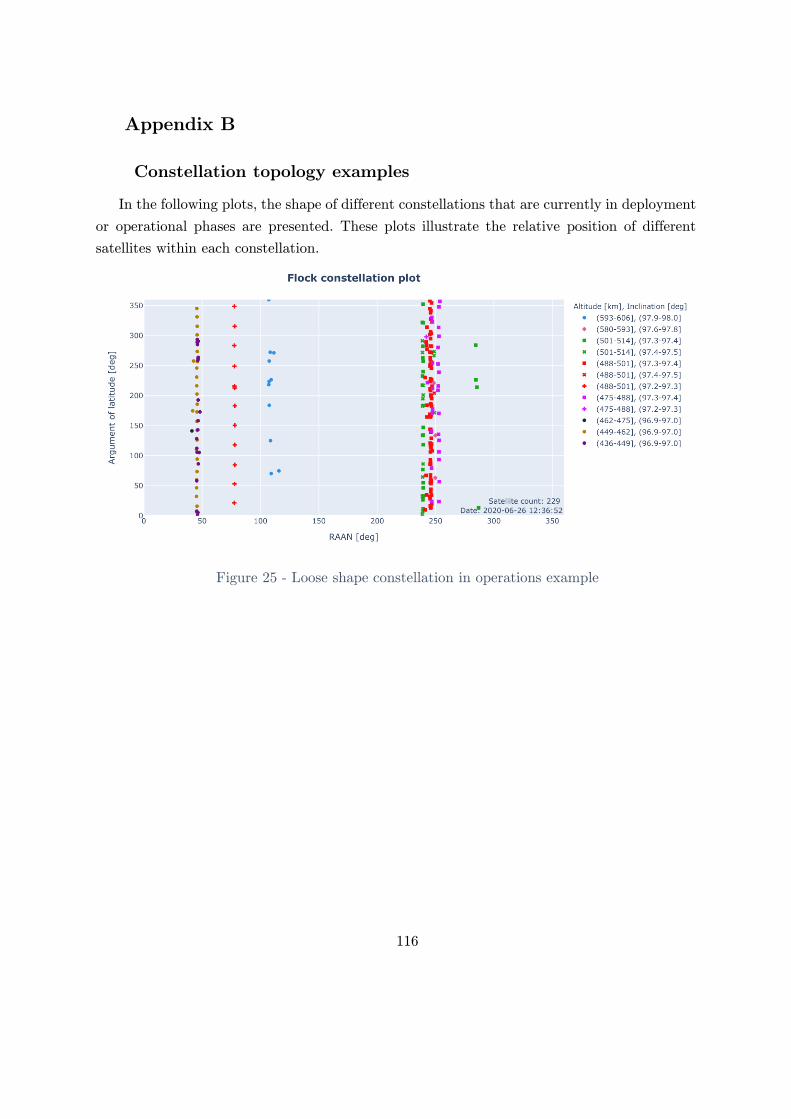
116
Appendix B
Constellation topology examples
In the following plots, the shape of different constellations that are currently in deployment
or operational phases are presented. These plots illustrate the relative position of different
satellites within each constellation.
Figure 25 - Loose shape constellation in operations example

117
Figure 26 - Operational tight shape constellation example
Figure 27 - Early stages of a constellation deployment example

118
Figure 28 - Tight shape constellation in deployment example

119
Appendix C – Architecture A1
Unsafe control actions table
Control
action
Not providing Providing Too early, too late,
out of order
Stopped too soon,
applied too long
Thrust UCA-A1.1: The
propulsion controller
does not generate
thrust when it is
armed and is
commanded to do it
[H3]
UCA-A1.2: The
propulsion controller
generates thrust in an
incorrect direction or
magnitude when it is
armed and
commanded to do it
[H3]
UCA-A1.3: The
propulsion controller
generates thrust when
it is armed, but it was
not commanded to do
it [H3]
UCA-A1.4: The
propulsion controller
generates thrust with
more than TBD of
delay when it is
armed and
commanded to do it.
[H3]
UCA-A1.5: The
propulsion controller
stops generating
thrust when there is
no alarm, it was
commanded to, and
the system is armed.
[H3]
UCA-A1.6: The
propulsion controller
keeps generating
thrust after being
commanded to stop
by a thrust=0 or
disarm command. [H3]
Torque UCA-A1.7: The
attitude controller
does not provide
torque when it is
needed to maintain or
follow a setpoint. [H1,
H3, H2, H4]
UCA-A1.8: The
attitude controller
provides a torque in
the wrong direction or
with the wrong
magnitude when it is
needed to maintain or
follow a setpoint. [H1,
H3, H2, H4]
UCA-A1.9: The
attitude control
subsystem provides a
torque when it is not
needed [H1, H2, H3,
H4]
UCA-A1.10: The
attitude controller
provides delayed
torques when is
needed to maintain or
follow a setpoint. [H1,
H3, H2, H4]
UCA-A1.11: The
attitude controller
stops applying torque
too soon when still
needed to maintain or
follow a setpoint. [H1,
H3, H2, H4]
UCA-A1.12: The
attitude controller
keeps applying torque
when not needed
anymore. [H1, H3, H2,
H4]
Arm UCA-A1.13: Satellite
controllers do not
provide an arm
command before a
propulsion command
when performing
orbital maneuvers
(because the satellite
is in an inadequate
orbit) [H3]
N/A UCA-A1.14: Mission
operations provide an
arm command too
early (>TBD minutes)
before an orbital
maneuver (resulting in
a waste of energy that
prevents the payload
from operating) [H1]
UCA.A1. 15: Satellite
controllers provide an
arm command too
late to perform an
orbital maneuver
when a satellite is in
an inadequate orbit.
[H3]
N/A

120
Disarm UCA-A1.16: Satellite
controllers do not
provide a disarm
command after
concluding orbital
maneuvers (resulting
in a waste of energy
that prevents the
payload from
operating) [H1]
UCA-A1.17: Satellite
controllers provide a
disarm command
when the system is
performing as
expected and is doing
orbital maneuvers
(resulting in
incomplete
maneuvers) [H3]
UCA-A1.18: Satellite
controllers provide a
disarm too late after
concluding orbital
maneuvers (resulting
in a waste of energy
that prevents the
payload from
operating) [H1]
N/A
Propulsio
n
command
UCA-A1.19: Satellite
controllers do not
provide propulsion
command when
requested in a burn
plan. [H3]
UCA-A1.20: Satellite
controllers provide a
propulsion command
when the satellite is
armed but was not
specified in the burn
plan. [H3]
UCA-A1.21: Satellite
controllers provide a
propulsion command
in a wrong direction
or magnitude when
the system is armed,
and it is specified in
the burn plan. [H3]
UCA-A1.22: Satellite
controllers provide a
propulsion command
when the system is
armed, and the
satellite has not
reached the correct
attitude. [H3]
UCA-A1.23: Satellite
controllers provide a
propulsion command
for an orbital
maneuver when the
propulsion subsystem
is not armed [H3]
UCA-A1.24: Satellite
controllers provide a
propulsion command
for an orbital
maneuver when the
satellite is doing a
payload maneuver
[H1]
UCA-A1.25: Satellite
controllers provide a
propulsion command
later than specified in
the burn plan when
the satellite is doing
orbital maneuvers
[H3]
N/A
Attitude
command
UCA-A1.26: Satellite
controllers do not
provide an attitude
command when
necessary for a
UCA-A1.28: Satellite
controllers provide an
attitude command
with the incorrect
mode or setpoint
UCA-A1.32: Satellite
controllers provide an
attitude command too
late when it is
required by a payload
N/A

121
payload or maneuver
operation [H1, H3]
UCA-A1.27: Satellite
controllers do not
provide a change
attitude mode when
the satellite is in an
unsafe attitude (i.e.,
sun on a payload, no
sun on solar panels,
etc.) [H4]
when it is needed by a
payload or a
maneuver operation
[H1, H2, H3, H4]
UCA-A1.29: Satellite
controllers provide an
attitude command
with a forbidden
setpoint and mode
when doing
maintenance
operations. [H4]
UCA-A1.30: Satellite
controllers provide an
attitude change when
a satellite does not
need it. [H1, H2, H3,
H4]
UCA-A1.31: Satellite
controllers provide an
attitude change for a
payload operation
when the satellite is
doing a maneuver
operation or vice-
versa. [H1, H3]
or maneuver operation
[H1, H2, H3]
Payload
on
UCA-A1.33: Satellite
controllers do not
provide a payload on
command before
sending ad-hoc
payload commands
when is needed [H1]
UCA-A1.34: Satellite
controllers provide a
payload on command
when the satellite is
over or pointing to a
forbidden area
(assuming that there
is an active payload
like a radio or a
radar) [H2]
UCA-A1.35: Satellite
controllers provide a
payload on command
when the satellite is in
a forbidden attitude
(resulting in a
damaged payload)
[H4]
N/A N/A
Payload
off
UCA-A1.36: Satellite
controllers do not
provide a payload off
command when it is
not needed anymore
(for active payloads or
wasting energy) [H1,
H2, H4]
N/A UCA-A1.37: Satellite
controllers provide a
payload off command
too late after a
payload operation
[H1, H2, H4]
UCA-A1.38: Satellite
controllers provide a
N/A

122
payload off command
when the satellite is
still performing a
payload operation,
and the subsystem
has no alarms[H1]
Burn
plan
UCA-A1.39: ODT
does not provide a
burn plan when a
satellite is in a
collision trajectory.
[H3.2]
UCA-A1.40: ODT
does not provide a
burn plan when a
satellite is reaching or
outside the location
requirement [H3.1]
UCA-A1.41: ODT
does not provide a
burn plan when a
satellite is in a reentry
trajectory over a
populated area. [H3.3]
UCA-A1.42: ODT
provides a burn plan
when a satellite is on
the correct orbit and
not in a collision or
reentry over a
populated area
trajectory [H3]
UCA-A1.43: ODT
provides a burn plan
when a satellite is
performing a payload
operation [H1, H3]
UCA-A1.44: ODT
provides a burn plan
with incorrect angles
or forces when a
satellite is in an
inadequate orbit[H3]
UCA-A1.45: ODT
provides a burn plan
that puts the satellite
in reentry trajectory
over a populated area
trajectory when
decommissioning a
satellite [H3]
UCA-A1.46: ODT
provides a burn plan
that puts the satellite
in a potential collision
trajectory when doing
station-keeping
maneuvers [H3]
UCA-A1.47: ODT
provides a burn plan
too late when the
satellite is on a
collision trajectory,
reentry trajectory
over a populated area
or reaching the limit
ofof the relative
position requirement
[H3]
N/A
Payload
plan
UCA-A1.48: Payload
team does not provide
a payload plan when
needed for a mission
goal [H1]
UCA-A1.49: Payload
provides a payload
plan when a satellite
is performing a
maneuver operation
[H1, H3]
UCA-A1.50: Payload
team provides a
payload plan with
incorrect parameters.
[H1]
UCA-A1.51: Payload
provides a payload
plan too late when the
needed for a mission
goal [H3]
N/A
Table 25 - A1 UCA TableComponent-level constraints

123
UCA System-level constraints
UCA-A1.1: The propulsion controller does not
generate thrust when it is armed and is
commanded to do it [H3]
SC-1: The propulsion controller must always generate
thrust when it is armed and commanded to do it
UCA-A1.2: The propulsion controller generates
thrust in an incorrect direction or magnitude when
it is armed and commanded to do it [H3]
SC-2: The propulsion controller must not generate trust
in a different direction or magnitude than requested
when armed.
UCA-A1.3: The propulsion controller generates
thrust when it is armed, but it was not commanded
to do it [H3]
SC-3: The propulsion controller must only generate
trust when it is armed and commanded to do it.
UCA-A1.4: The propulsion controller generates
thrust with more than TBD of delay when it is
armed and commanded to do it. [H3]
SC-4: The propulsion controller must start producing
thrust within TBD seconds after being commanded to
do it.
UCA-A1.5: The propulsion controller stops
generating thrust when there is no alarm, it was
commanded to, and the system is armed. [H3]
SC-5: The propulsion controller must generate thrust for
the amount of time commanded and no less than that
when there are no problems with it.
UCA-A1.6: The propulsion controller keeps
generating thrust after being commanded to stop
by a thrust=0 or disarm command. [H3]
SC-6: The propulsion controller must not generate
thrust after being commanded to stop by a thrust=0
command or disarmed.
UCA-A1.7: The attitude controller does not
provide torque when it is needed to maintain or
follow a setpoint. [H1, H3, H2, H4]
SC-7: The attitude controller must always generate
torque when it is needed to maintain or follow a
setpoint.
UCA-A1.8: The attitude controller provides a
torque in the wrong direction or with the wrong
magnitude when it is needed to maintain or follow
a setpoint. [H1, H3, H2, H4]
SC-8: The attitude controller must provide torque in the
correct direction and magnitude necessary to control the
attitude of the satellite.
UCA-A1.9: The attitude control subsystem
provides a torque when it is not needed [H1, H2,
H3, H4]
SC-9: The attitude controller must only provide a
torque when it is needed because the satellite is not in
the setpoint.
UCA-A1.10: The attitude controller provides
delayed torques when is needed to maintain or
follow a setpoint. [H1, H3, H2, H4]
SC-10: The attitude controller must provide torque with
less than TBD seconds after detected to be needed
UCA-A1.11: The attitude controller stops applying
torque too soon when still needed to maintain or
follow a setpoint. [H1, H3, H2, H4]
SC-11: The attitude controller must provide torque for
all the time needed to maintain or follow a setpoint.
UCA-A1.12: The attitude controller keeps applying
torque when not needed anymore. [H1, H3, H2, H4]
SC-12: The attitude controller must only apply torque
when needed.

124
UCA-A1.13: Satellite controllers do not provide an
arm command before a propulsion command when
performing orbital maneuvers (because the satellite
is in an inadequate orbit) [H3]
SC-13: An arm command must always be e provided
before providing propulsion commands.
UCA-A1.14: Satellite controllers provide an arm
command too early (>TBD minutes) before an
orbital maneuver (resulting in a waste of energy
that prevents the payload from operating) [H1]
SC-14: An arm command must be sent not more than
TBD minutes before a propulsion command. (to save
energy).
UCA.A1. 15: Satellite controllers provide an arm
command too late to perform an orbital maneuver
when a satellite is in an inadequate orbit. [H3]
SC-15: An arm command must be sent not later than
TBD minutes before a propulsion command. (to allow
time to prepare the system)
UCA-A1.16: Satellite controllers do not provide a
disarm command after concluding orbital
maneuvers (resulting in a waste of energy that
prevents the payload from operating) [H1]
SC-16: A disarm command must be provided when
orbital maneuvers are finished (to save energy and to
prevent unexpected thrusting)
UCA-A1.17: Satellite controllers provide a disarm
command when the system is performing as
expected and is doing orbital maneuvers (resulting
in incomplete maneuvers) [H3]
SC-17: A disarm command must be only provided when
no more propulsion commands are needed.
UCA-A1.18: Satellite controllers provide a disarm
too late after concluding orbital maneuvers
(resulting in a waste of energy that prevents the
payload from operating) [H1]
SC-18: A disarm command must be provided as soon as
the last propulsion command is issued for a maneuver
(to save energy and to prevent unexpected thrusting)
UCA-A1.19: Satellite controllers do not provide
propulsion command when requested in a burn
plan. [H3]
SC-19: Propulsion commands must be sent if requested
in a burn plan. (they cannot be skipped by all means)
UCA-A1.20: Satellite controllers provide a
propulsion command when the satellite is armed
but was not specified in the burn plan. [H3]
SC-20: Propulsion commands must only be provided if
specified in a burn plan.
UCA-A1.21: Satellite controllers provide a
propulsion command in a wrong direction or
magnitude when the system is armed, and it is
specified in the burn plan. [H3]
SC-21: Propulsion commands must always be in the
same direction and magnitude as specified in the burn
plan.
UCA-A1.22: Satellite controllers provide a
propulsion command when the system is armed,
SC-22: Propulsion commands must be sent only when
the satellite has acquired the necessary attitude for the
burn.

125
and the satellite has not reached the correct
attitude. [H3]
UCA-A1.23: Satellite controllers provide a
propulsion command for an orbital maneuver when
the propulsion subsystem is not armed [H3]
SC-23: The propulsion subsystem must be armed before
providing propulsion commands.
UCA-A1.24: Satellite controllers provide a
propulsion command for an orbital maneuver when
the satellite is doing a payload maneuver [H1]
SC-24: Propulsion commands must not be provided
when a satellite is doing a payload operation.
UCA-A1.25: Satellite controllers provide a
propulsion command later than specified in the
burn plan when the satellite is doing orbital
maneuvers [H3]
SC-25: Propulsion commands must be provided at the
specific time required by the burn plan.
UCA-A1.26: Satellite controllers do not provide an
attitude command when necessary for a payload or
maneuver operation [H1, H3]
SC-26: Attitude commands must always be issued
before doing any payload or maneuver operation.
UCA-A1.27: Satellite controllers do not provide a
change attitude mode when the satellite is in an
unsafe attitude (i.e., sun on a payload, no sun on
solar panels, etc.) [H4]
SC-27: An attitude command must be provided if the
satellite has an unsafe attitude.
SC-28: Unsafe attitude must be specified before starting
operations.
UCA-A1.28: Satellite controllers provide an
attitude command with the incorrect mode or
setpoint when it is needed by a payload or a
maneuver operation [H1, H2, H3, H4]
SC-29: Attitude commands must be provided with the
exact mode and setpoint as specified in a payload or
maneuver operation.
UCA-A1.29: Satellite controllers provide an
attitude command with a forbidden setpoint and
mode when doing maintenance operations. [H4]
SC-30: Attitude commands with forbidden setpoint
must never be provided.
UCA-A1.30: Satellite controllers provide an
attitude change when a satellite does not need it.
[H1, H2, H3, H4]
SC-31: Attitude commands must only be provided when
required by a payload, maneuver, or maintenance
operation.
UCA-A1.31: Satellite controllers provide an
attitude change for a payload operation when the
satellite is doing a maneuver operation or vice-
versa. [H1, H3]
SC-32: Attitude commands for an operation must not be
provided during another operation.
UCA-A1.32: Satellite controllers provide an
attitude command too late when it is required by a
payload or maneuver operation [H1, H2, H3]
SC-33: Attitude commands must be provided TBD
seconds in advance to an operation when a specific
attitude is required. (to let it stabilize)

126
UCA-A1.33: Satellite controllers do not provide a
payload on command before sending ad-hoc
payload commands when is needed [H1]
SC-34: A payload on command must be provided before
any ad-hoc command is sent to the payload.
UCA-A1.34: Satellite controllers provide a payload
on command when the satellite is over or pointing
to a forbidden area (assuming that there is an
active payload like a radio or a radar) [H2]
SC-35: A payload on command must not be provided
over forbidden areas.
SC-36: Forbidden areas must be provided before
starting operations.
UCA-A1.35: Satellite controllers provide a payload
on command when the satellite is in a forbidden
attitude (resulting in a damaged payload) [H4]
SC-37: A payload on command must not be provided
when the satellite has a forbidden attitude.
SC-38: Forbidden attitudes must be provided before
starting operations.
UCA-A1.36: Satellite controllers do not provide a
payload off command when it is not needed
anymore (for active payloads or wasting energy)
[H1, H2, H4]
SC-39: A payload off command must be provided after
concluding payload operation (to avoid wasting energy,
damaging the payload or using it over forbidden areas)
UCA-A1.37: Satellite controllers provide a payload
off command too late after a payload operation
[H1, H2, H4]
SC-40: A payload off command must be sent
immediately after concluding payload operations. (to
save energy)
UCA-A1.38: Satellite controllers provide a payload
off command when the satellite is still performing a
payload operation, and the subsystem has no
alarms[H1]
SC-41: A payload off command must not be sent when
the satellite is doing a payload operation.
UCA-A1.39: ODT does not provide a burn plan
when a satellite is in a collision trajectory. [H3.2]
SC-42: A burn plan must always be provided when a
satellite is in a collision trajectory to avoid it.
UCA-A1.40: ODT does not provide a burn plan
when a satellite is reaching or outside the location
requirement [H3.1]
SC-43: A burn plan must always be provided when a
satellite is reaching the limit of or outside the location
requirement to correct it.
UCA-A1.41: ODT does not provide a burn plan
when a satellite is in a reentry trajectory over a
populated area. [H3.3]
SC-44: A burn plan must always be provided if a
satellite is in a reentry trajectory over a populated area
to avoid it.
UCA-A1.42: ODT provides a burn plan when a
satellite is on the correct orbit and not in a
collision or reentry over a populated area trajectory
[H3]
SC-45: Burn plans must not be provided when the
satellite is on the correct orbit and not in a collision or
reentry over populated area trajectory.

127
UCA-A1.43: ODT provides a burn plan when a
satellite is performing a payload operation [H1, H3]
SC-46: Burn plans must not be provided when a
satellite is doing a payload operation. (priorities TBD)
UCA-A1.44: ODT provides a burn plan with
incorrect angles or forces when a satellite is in an
inadequate orbit[H3]
SC-47: Burn plans must be provided with correct angles
and forces for each specific satellite when needed.
UCA-A1.45: ODT provides a burn plan that puts
the satellite in reentry trajectory over a populated
area trajectory when decommissioning a satellite
[H3]
SC-48: Burn plans must not put a satellite in a reentry
trajectory over a populated area when decommissioning
a satellite.
UCA-A1.46: ODT provides a burn plan that puts
the satellite in a potential collision trajectory when
doing station-keeping maneuvers [H3]
SC-49: Burn plans must not put a satellite in a collision
trajectory to another orbiting body.
UCA-A1.47: ODT provides a burn plan too late
when the satellite is on a collision trajectory,
reentry trajectory over a populated area or
reaching the limit ofof the relative position
requirement [H3]
SC-50: Burn plans must be timely (TBD) provided
when a satellite is in a collision trajectory, reentry
trajectory over a populated area, or reaching the limit
ofof the position requirement.
UCA-A1.48: Payload team does not provide a
payload plan when needed for a mission goal [H1]
SC-51: Payload plans must be provided when required
by a mission goal.
UCA-A1.49: Payload provides a payload plan when
a satellite is performing a maneuver operation [H1,
H3]
SC-52: Payload plans must not be provided when a
satellite is doing maneuver operations.
UCA-A1.50: Payload team provides a payload plan
with incorrect parameters. [H1]
SC-53: Payload plans must be provided with the correct
parameters.
UCA-A1.51: Payload provides a payload plan too
late when the needed for a mission goal [H3]
SC-54: Payload plans must be timely (TBD) provided
when required by a mission goal.
Table 26 - A1 Component-level constraints
Causal scenarios
UCA Scenarios
UCA-A1.1: The
propulsion controller
does not generate thrust
when it is armed and is
commanded to do it
[H3]
Scenario 1: The Propulsion subsystem physical controller goes into fault-handling
or shut-down when a propulsion command is issued due to a physical controller
failure, causing the thrust not to be generated. As a result, the maneuver is
flawed, and the satellite ends in an inadequate orbit. [H3]
Scenario 2: The propulsion subsystem controller is armed and is commanded to
generate thrust by a propulsion command. The propulsion subsystem does not

128
generate thrust because the algorithm to control the actuators is not designed for
the particular actuators in the satellite (it was incorrectly updated with the
software for another satellite). As a result, no thrust is generated, the orbital
maneuver is flawed, and the satellite ends in an inadequate orbit. [H3]
Scenario 3: The propulsion subsystem controller is armed and is commanded to
generate thrust by a propulsion command. The propulsion subsystem does not
generate thrust because the algorithm to control the actuators become inadequate
over time. This can happen if, for example, a valve degraded and needs additional
power to open. As a result, no thrust is generated, the orbital maneuver is flawed,
and the satellite ends in an inadequate orbit. [H3]
Scenario 4: The propulsion subsystem controller is armed and is commanded to
generate thrust. The propulsion subsystem does not generate thrust because
provided information during the launch preparation of the satellite incorrectly
loaded the amount of propellant as empty. As a result, no thrust is generated, the
orbital maneuver is flawed, and the satellite ends in an inadequate orbit. [H3]
Scenario 5: The propulsion subsystem controller is armed and is commanded to
generate thrust by a propulsion command. The actuators are behaving as
expected, but the propulsion subsystem does not generate thrust because it
incorrectly believes there is a problem with them and goes to fault-handling mode.
This flawed process model will occur if incorrect feedback is received from the
actuator. This can happen if any of the following occur:
- A sensor on the actuators fails to report incorrect feedback (i.e., a
damaged pressure transducer)
- Sensors on the actuators are not suited for that specific operational
condition (i.e., an out of scale pressure transmitter)
- A sensor signal from the actuator is corrupted in the transmission.
As a result, no thrust is generated, the orbital maneuver is flawed, and the
satellite ends in an inadequate orbit. [H3]
Scenario 6: The propulsion subsystem controller is armed and is commanded to
generate thrust by a propulsion command. The actuators are behaving as
expected, but the propulsion subsystem does not generate thrust because it
believes there is a problem with them and disarms the subsystem. This flawed
process model will occur if correct feedback (i.e., confirmation of a valve opening)
is received with delay or never received. This can happen if any of the following
occur:
- There is a wiring or communication problem between a sensor and the
controller.
- A sensor fails and does not report any data.
- There is a problem reading a sensor data in the controller (i.e., the
controller is busy with another higher-level task)

129
As a result, no thrust is generated, and the orbital maneuver is flawed, and the
satellite ends in an inadequate orbit. [H3]
UCA-A1.2: The
propulsion controller
generates thrust in an
incorrect direction or
magnitude when it is
armed and commanded
to do it [H3]
Scenario 7: The propulsion subsystem controller is commanded with a certain
amount of thrust and direction, but a failure in the controller (like a broken
output stage transistor for an analog actuator or a broken communication
interface for a digital one) makes it generate incorrectly in value or direction. As a
result, the maneuver is flawed, and the satellite ends in an inadequate orbit [H3].
Scenario 8: The propulsion subsystem controller is armed and is commanded to
generate thrust by a propulsion command. The propulsion generates thrust with
an incorrect magnitude or direction because the algorithm to control the actuators
is not designed for the particular actuators in the satellite (it was incorrectly
updated with the software for another satellite). As a result, no thrust is
generated, and the orbital maneuver is flawed, and the satellite ends in an
inadequate orbit. [H3]
Scenario 9: The propulsion subsystem controller is armed and is commanded to
generate thrust by a propulsion command. The propulsion subsystem generates
thrust with an incorrect magnitude or direction because the algorithm to control
the actuators become inadequate over time. This can happen if, for example, the
thrusters are misaligned due to a loss of structural integrity during the launch or a
collision or worn-out thrusters. As a result, the orbital maneuver is flawed, and
the satellite ends in an inadequate orbit [H3].
Scenario 10: The propulsion subsystem controller is armed and is commanded to
generate thrust. The propulsion subsystem generates thrust with an incorrect
magnitude and/or direction because provided information about the configuration
of the actuator during the launch preparation was incorrectly loaded or updated in
flight (from another satellite or with typos). As a result, a maneuver is flawed,
and the satellite ends in an inadequate orbit [H3].
Scenario 11: (1.4.1) The propulsion subsystem controller is armed and is
commanded to generate thrust by a propulsion command. The propulsion
subsystem generates incorrectly thrust in value or direction because it incorrectly
believes it is doing it correctly. This flawed process model will occur if incorrect
feedback is received from the actuator. This can happen if any of the following
occur:
- Sensors on the actuators fail reporting incorrect feedback (i.e., a damaged
pressure transducer)
- Sensors on the actuators are not suited for that specific operational
condition (i.e., an out of scale pressure transmitter)
- A sensor signal from the actuator is corrupted in the transmission.
As a result, a maneuver is flawed, and the satellite ends in an inadequate orbit
[H3].

130
Scenario 12: (1.4.3) The propulsion subsystem controller is armed and is
commanded to generate thrust by a propulsion command. The propulsion
subsystem generates incorrectly thrust in value or direction because it incorrectly
believes it is doing it correctly. This flawed process model will occur if correct
feedback is received with a certain delay. This can happen if any of the following
occur:
- There is a wiring or communication problem between a sensor and the
controller.
- There is a problem reading a sensor data in the controller (i.e., the
controller is busy with a higher-level task)
As a result, a maneuver is flawed, and the satellite ends in an inadequate orbit
[H3].
Scenario 13: (1.4.3) The propulsion subsystem controller is armed and is
commanded to generate thrust by a propulsion command. The propulsion
subsystem generates incorrectly thrust in value or direction because it there is no
direct feedback from the controller process to close the loop (assuming that the
feedback from the actuator might be wrong: i.e., a Hall effect thruster might have
the same feedback from the actuator if there is xenon coming out of the system or
not, and there is no way to measure it). As a result, a maneuver is flawed, and the
satellite ends in an inadequate orbit [H3].
UCA-A1.3: The
propulsion controller
generates thrust when it
is armed, but it was not
commanded to do it
[H3]
Scenario 14: (1.1) The propulsion subsystem physical controller fails triggering a
thrust signal to the actuator. As a result, thrust command is unexpectedly
generated, and the satellite ends in an inadequate orbit. [H3]
Scenario 15: The propulsion subsystem is unarmed. A propulsion command was
sent previously that was not cleared (i.e., the satellite went to the fault-handling
mode and recovered but did not clear the thrust command). When the controller
is changed to arm mode, the systems starts generating thrust. As a result, thrust
is unexpectedly generated, and the satellite ends in an inadequate orbit. [H3]
UCA-A1.4: The
propulsion controller
generates thrust with
more than TBD of
delay when it is armed
and commanded to do
it. [H3]
Scenario 16: (1.2.1) The propulsion subsystem is commanded to produce thrust,
but processing delays within the controller result in a delayed thrust signal to the
actuator. As a result, a maneuver is flawed, and the satellite ends in an
inadequate orbit [H3].
UCA-A1.5: The
propulsion controller
stops generating thrust
when there is no alarm,
it was commanded to,
Scenario 17: (1.1) The Propulsion subsystem physical controller fails or goes offline
during a propulsion maneuver, and the thrust is interrupted. As a result, a
maneuver is flawed, and the satellite ends in an inadequate orbit [H3].

131
and the system is
armed. [H3]
Scenario 18: (1.4.1) The subsystem is producing thrust, and the actuators are
behaving as expected. The propulsion subsystem stops sending a thrust command
to the actuators because it believes there is a problem with them. This flawed
process model will occur if incorrect feedback is received from the actuator. This
can happen if any of the following occur:
- Sensors on the actuators fail reporting incorrect feedback (i.e., a damaged
pressure transducer)
- Sensors on the actuators are not suited for that specific operational
condition (i.e., an out of scale pressure transmitter)
- A sensor signal from the actuator is corrupted in the transmission.
As a result, the thrust is interrupted, and the satellite ends in an inadequate orbit
[H3].
Scenario 19: (1.4.3) The actuators are behaving as expected. The propulsion
subsystem stops sending a thrust command to the actuators because it believes
there is a problem with them. This flawed process model will occur if the feedback
is never received. This can happen if any of the following occur:
- There is a wiring or communication problem between a sensor and the
controller.
- A sensor fails and does not report any data.
There is a problem reading a sensor data in the controller (i.e., the controller is
busy with another higher level task)
As a result, the thrust is interrupted, and the satellite ends in an inadequate orbit
[H3].
UCA-A1.6: The
propulsion controller
keeps generating thrust
after being commanded
to stop by a thrust=0
or disarm command.
[H3]
Scenario 20: (1.1) The propulsion subsystem's physical controller fails and does
not stop the actuator (a fixed transistor, for example). As a result, the thrust
command is generated for more time than required, and the satellite ends in an
inadequate orbit [H3].
UCA-A1.7: The attitude
controller does not
provide torque when it
is needed to maintain or
follow a setpoint. [H1,
H3, H2, H4]
Scenario 21: (1.1) The attitude controller fails or goes offline when the attitude
subsystem needs to generate torque to maintain or follow a setpoint. As a result,
the required attitude is not met, and a payload operation is flawed [H1], a
maneuver is done unproperly, and the satellite ends in an inadequate orbit [H3],
the satellite ends up in an unsafe attitude that can damage the hardware [H4] or
the satellite uses an active payload over a forbidden target [H2]
Scenario 22: The attitude controller does not generate torque maintain or follow a
setpoint because the algorithm is not designed for the particular actuators and
sensors in the satellite since it was incorrectly updated with the software for
another satellite. As a result, the required attitude is not met, and a payload
operation is flawed [H1], a maneuver is done unproperly, and the satellite ends in
an inadequate orbit [H3], the satellite ends up in an unsafe attitude that can

132
damage the hardware [H4] or the satellite uses an active payload over a forbidden
target [H2]
Scenario 23: (1.4.1) The attitude controller needs to generate torque maintain or
follow a setpoint. The subsystem does not command the actuators to generate
torque because it believes it is already in the setpoint. This flawed process model
will occur if incorrect attitude feedback is received from the sensors. This can
happen if any of the following occur:
- The satellite attitude is drifting slowly from the setpoint, but the
attitude sensors do not detect it because they are not designed for that
scale.
- The attitude sensor is flawed and incorrectly indicate that the attitude is
in the setpoint.
- The attitude sensor data is corrupted in the transmission and does not
show a drift from the setpoint.
As a result, the required attitude is not met, and a payload operation is flawed
[H1], a maneuver is done unproperly, and the satellite ends in an inadequate orbit
[H3], the satellite ends up in an unsafe attitude that can damage the hardware
[H4] or the satellite uses an active payload over a forbidden target [H2]
Scenario 24: (1.4.3) The attitude controller needs to generate torque to change or
maintain the attitude specified. The subsystem does not command the actuators
to generate torque because it believes it is not needed. This flawed process model
will occur if attitude feedback is never received or received late from the attitude
sensors. This can happen if any of the following occur:
- The sensor data takes too long to arrive at the controller due to a
communication bus overload, and the subsystem uses old data.
- The sensor fails and does not report any data, and the subsystem uses
old data.
- There is a problem reading the sensor data in the controller, and the
subsystem uses old data.
As a result, the required attitude is not met, and a payload operation is flawed
[H1], a maneuver is done unproperly, and the satellite ends in an inadequate orbit
[H3], the satellite ends up in an unsafe attitude that can damage the hardware
[H4] or the satellite uses an active payload over a forbidden target [H2]
UCA-A1.8: The attitude
controller provides a
torque in the wrong
direction or with the
wrong magnitude when
it is needed to maintain
or follow a setpoint.
[H1, H3, H2, H4]
Scenario 25: (1.1) The attitude controller needs to generate torque to maintain or
follow a setpoint but a failure in the controller output (like a broken output stage
transistor for an analog actuator or a broken communication interface for a digital
one) incorrectly commands the actuator. As a result, the required attitude is not
met, and a payload operation is flawed [H1], a maneuver is done unproperly, and
the satellite ends in an inadequate orbit [H3], the satellite ends up in an unsafe
attitude that can damage the hardware [H4] or the satellite uses an active payload
over a forbidden target [H2]

133
Scenario 26: (1.2.1/1.2.2) The attitude controller needs to generate torque to
maintain or follow a setpoint but a flawed specification/implementation of the
control algorithm (incorrect reference frame, incorrect units, incorrect time
constants, a sequence of angles, etc.) commands the actuators with the wrong
magnitude or direction. As a result, the required attitude is not met, and a
payload operation is flawed [H1], a maneuver is done unproperly, and the satellite
ends in an inadequate orbit [H3], the satellite ends up in an unsafe attitude that
can damage the hardware [H4] or the satellite uses an active payload over a
forbidden target [H2]
Scenario 27: (1.2.3) The attitude controller needs to generate torque to maintain
or follow a setpoint but commands the actuators with the wrong magnitude or
direction because the inertia tensor was not updated after a change in mass during
a propulsion maneuver or after a change in the structure of the satellite (i.e.,
deployment of a boom). As a result, the required attitude is not met, and a
payload operation is flawed [H1], a maneuver is done unproperly, and the satellite
ends in an inadequate orbit [H3], the satellite ends up in an unsafe attitude that
can damage the hardware [H4] or the satellite uses an active payload over a
forbidden target [H2]
Scenario 28: The attitude controller needs to generate torque to maintain or follow
a setpoint. The sensors and the actuators are working as expected but command
the actuators with the wrong magnitude or direction because provided information
about the actuators and sensors position and orientation during the launch
preparation was incorrectly loaded or updated in flight (from another satellite for
example or with typos). As a result, the required attitude is not met, and a
payload operation is flawed [H1], a maneuver is done unproperly, and the satellite
ends in an inadequate orbit [H3], the satellite ends up in an unsafe attitude that
can damage the hardware [H4] or the satellite uses an active payload over a
forbidden target [H2]
Scenario 29: The attitude controller needs to generate torque to maintain or follow
a setpoint but commands the actuators with the wrong magnitude or direction
because the algorithm is not designed for the particular actuators and sensors in
the satellite since it was incorrectly updated with the software for another
satellite. As a result, the required attitude is not met, and a payload operation is
flawed [H1], a maneuver is done unproperly, and the satellite ends in an
inadequate orbit [H3], the satellite ends up in an unsafe attitude that can damage
the hardware [H4] or the satellite uses an active payload over a forbidden target
[H2]
Scenario 30: (1.2.3) The attitude controller needs to generate torque to maintain
or follow a setpoint but commands the actuators with the wrong magnitude or
direction because the control algorithm becomes inadequate over time since it did
not consider the degradation of the actuators. As a result, the required attitude is

134
not met, and a payload operation is flawed [H1], a maneuver is done unproperly,
and the satellite ends in an inadequate orbit [H3], the satellite ends up in an
unsafe attitude that can damage the hardware [H4] or the satellite uses an active
payload over a forbidden target [H2]
Scenario 31: (1.4.1) The attitude controller needs to generate torque to maintain
or follow a setpoint. The controller commands the actuators with the wrong
magnitude or direction because it believes that is the necessary correction to do.
This flawed process model will occur if correct feedback is received with delay or
never received. This can happen if any of the following occur:
- There is a wiring problem between the sensor and the controller.
- The sensor fails and does not report any data.
- There is a problem reading the sensor data in the controller
As a result, the required attitude is not met, and a payload operation is flawed
[H1], a maneuver is done unproperly, and the satellite ends in an inadequate orbit
[H3], the satellite ends up in an unsafe attitude that can damage the hardware
[H4] or the satellite uses an active payload over a forbidden target [H2]
UCA-A1.9: The attitude
control subsystem
provides a torque when
it is not needed [H1, H2,
H3, H4]
Scenario 32: (1.1) The attitude physical controller fails triggering a torque
command to the actuators. As a result, the attitude is incorrectly altered, and the
payload operation is flawed [H1], a maneuver is done unproperly, and the satellite
ends in an inadequate orbit [H3], the satellite ends up in an unsafe attitude that
can damage the hardware [H4], or the satellite uses an active payload over a
forbidden target [H2].
Scenario 33: The attitude is as expected, and the controller does not need to
correct it. The controller provides a torque command to the actuators because it
believes that is not in the correct attitude. This flawed process model will occur if
incorrect attitude feedback is received from the sensors. This can happen if any of
the following occur:
- The attitude sensor is flawed and incorrectly indicate the attitude (a
broken sensor for example)
- The attitude sensor bias has changed inadvertently due to solar radiation
effects.
- The information provided by the GPS is flawed, and the sensors
incorrectly calculate the attitude.
As a result, the required attitude is not met, and a payload operation is flawed
[H1], a maneuver is done unproperly, and the satellite ends in an inadequate orbit
[H3], the satellite ends up in an unsafe attitude that can damage the hardware
[H4] or the satellite uses an active payload over a forbidden target [H2]
Scenario 34: The attitude is as expected, and the controller does not need to
correct it. The controller provides a torque command to the actuators because it
believes that it is not in the correct attitude. This can happen if incorrect

135
information about the actuators and sensors position and orientation flight (from
another satellite or with typos, for example) is provided to the satellite during a
software update. As a result, the required attitude is not met, and a payload
operation is flawed [H1], a maneuver is done unproperly, and the satellite ends in
an inadequate orbit [H3], the satellite ends up in an unsafe attitude that can
damage the hardware [H4] or the satellite uses an active payload over a forbidden
target [H2]
Scenario 35: The attitude is as expected, and the controller does not need to
correct it. The controller is restarted (because of a software update, maintenance
operation, fault-handling, etc.), and the default attitude at startup is used until
new data is determined and fed by the sensors. With the default attitude values,
it incorrectly believes that a corrective torque is needed. As a result, the required
attitude is not met, and a payload operation is flawed [H1], a maneuver is done
unproperly, and the satellite ends in an inadequate orbit [H3], the satellite ends up
in an unsafe attitude that can damage the hardware [H4] or the satellite uses an
active payload over a forbidden target [H2]
UCA-A1.10: The
attitude controller
provides delayed
torques when is needed
to maintain or follow a
setpoint. [H1, H3, H2,
H4]
Scenario 36: (1.2.1) The attitude subsystem needs to generate torque to change or
maintain the attitude of a satellite, but processing delays within the controller
result in a delayed torque command to the actuator. As a result, the required
attitude is not met, and a payload operation is flawed [H1], a maneuver is done
unproperly, and the satellite ends in an inadequate orbit [H3], the satellite ends up
in an unsafe attitude that can damage the hardware [H4] or the satellite uses an
active payload over a forbidden target [H2]
Scenario 37: (1.4.3) The attitude subsystem needs to generate torque to change or
maintain the attitude of the satellite. The controller provides a delayed control
action to the actuators because the information from the sensors is delayed. This
can happen if any of the following occur:
- Sensors are taking more than usual to update the attitude
- Sensors are working as expected, but communication problems prevent
the messages from arriving on time.
- The controller is busy with higher-priority tasks, and the reading of the
new inputs from the sensors is delayed.
As a result, the required attitude is not met, and a payload operation is flawed
[H1], a maneuver is done unproperly, and the satellite ends in an inadequate orbit
[H3], the satellite ends up in an unsafe attitude that can damage the hardware
[H4] or the satellite uses an active payload over a forbidden target [H2]
UCA-A1.11: The
attitude controller stops
applying torque too
soon when still needed
to maintain or follow a
Scenario 38: (1.1) The attitude physical controller fails or goes offline, causing the
torque not to be generated while the system still needs it. As a result, the required
attitude is not met, and the payload operation is flawed [H1], a maneuver is done
unproperly, and the satellite ends in an inadequate orbit [H3], the satellite ends up

136
setpoint. [H1, H3, H2,
H4]
in an unsafe attitude that can damage the hardware [H4] or the satellite uses an
active payload over a forbidden target [H2]
Scenario 39: (1.4.1) The attitude actuators and sensors are behaving as expected.
The attitude controller stops sending a torque command to the actuators because
it incorrectly believes there is a problem with any of them. This flawed process
model will occur if an alarm is received, out of range data is received, or no data is
received from the actuator’s sensors or the attitude sensors. This can happen if
any of the following occur:
- A sensor fails reporting an incorrect, faulty condition or out of range
values.
- Sensor information never arrives at the controller, and the controller
assumes it is non-working.
- There is a problem reading the sensor data in the controller
As a result, the required attitude is not met, and the payload operation is flawed
[H1], a maneuver is done unproperly, and the satellite ends in an inadequate orbit
[H3], the satellite ends up in an unsafe attitude that can damage the hardware
[H4] or the satellite uses an active payload over a forbidden target [H2]
Scenario 40: (1.2.1 / 1.2.2) The attitude subsystem needs to generate torque to
change or maintain the attitude of the satellite. The controller stops sending
torque commands to the actuators because it incorrectly believes that has reached
the setpoint. This flawed process model will occur if the dead-band of the
controller is incorrectly specified/configured. As a result, the required attitude is
not met, and the payload operation is flawed [H1], a maneuver is done unproperly,
and the satellite ends in an inadequate orbit [H3], the satellite ends up in an
unsafe attitude that can damage the hardware [H4] or the satellite uses an active
payload over a forbidden target [H2]
UCA-A1.12: The
attitude controller keeps
applying torque when
not needed anymore.
[H1, H3, H2, H4]
Scenario 41: (1.1) The attitude subsystem physical controller fails preventing it
from stopping the actuator (a wheel accelerating). As a result, the required
attitude is not met, and the payload operation is flawed [H1], a maneuver is done
unproperly, and the satellite ends in an inadequate orbit [H3], the satellite ends up
in an unsafe attitude that can damage the hardware [H4] or the satellite uses an
active payload over a forbidden target [H2]
Scenario 42: (1.4.3) The attitude of the satellite arrived at the setpoint, but the
controller keeps commanding the actuators because the information from the
sensors is delayed. This can happen if any of the following occur:
- Sensors are taking more than usual to update the attitude
- Sensors are working as expected, but communication problems prevent
the messages from arriving on time.
- The controller is busy with higher-priority tasks, and the reading of the
new inputs from the sensors is delayed.

137
As a result, the required attitude is not met, and a payload operation is flawed
[H1], a maneuver is done unproperly, and the satellite ends in an inadequate orbit
[H3], the satellite ends up in an unsafe attitude that can damage the hardware
[H4] or the satellite uses an active payload over a forbidden target [H2]
UCA-A1.13: Satellite
controllers do not
provide an arm
command before a
propulsion command
when performing orbital
maneuvers (because the
satellite is in an
inadequate orbit) [H3]
Scenario 43: Satellite controllers are about to do orbital maneuvers as requested
by a burn plan when a satellite is in an inadequate orbit. The propulsion
subsystem is disarmed. The satellite controller does not send the arm command
because the operating procedures did not specify that an arm command should be
sent before starting maneuver operations. As a result, no thrust will be generated
in the following propulsion command, and the satellite stays in an inadequate
orbit. [H3]
Scenario 44: Satellite controllers are about to do orbital maneuvers as requested
by a burn plan when a satellite is in an inadequate orbit. The propulsion
subsystem is disarmed. The satellite controller does not send the arm command
due to lack of training or because it is busy with another task. As a result, no
thrust will be generated in the following propulsion command, and the satellite
stays in an inadequate orbit. [H3]
Scenario 45: Satellite controllers are about to do orbital maneuvers as requested
by a burn plan when a satellite is in an inadequate orbit. The satellite was armed
and by a satellite controller command, but now the controller is disarmed due to
an unexpected reboot. The satellite controllers do not send an arm command
before issuing a propulsion command because they do not realize the indirect
change of mode. This can happen if:
- Satellite controllers are not trained to check for arm/disarm before each
command or periodically.
- Satellite controllers are unaware that this can happen
- Satellite controllers do not check the telemetry because they are
overloaded with other tasks (like supervising other satellites).
- The status display is not easily accessible in the controller screen.
- The mode never arrives due to communications problems or because the
satellite is not in contact with the ground.
As a result, no thrust will be generated in the following propulsion command, and
the satellite stays in an inadequate orbit [H3]
Scenario 46: Satellite controllers are about to do orbital maneuvers as requested
by a burn plan when a satellite is in an inadequate orbit. The propulsion
subsystem is disarmed. The satellite Satellite controllers do not provide the arm
command because they incorrectly believe that the subsystem is armed. This
flawed process model will occur if the current arm/disarm status is received, but it
is incorrectly interpreted or ignored by the operator. This can happen if any of the
following occur:

138
- The operator is inadvertently looking at the telemetry of another
satellite.
- The operator ignores the new value on the screen and assumes it is
armed because it usually is.
- The status display is not easily accessible in the controller screen.
- The telemetry is coded ambiguously or confusingly (using numbers
instead of words for example)
As a result, no thrust will be generated in the following propulsion command, and
the satellite stays in an inadequate orbit [H3]
UCA-A1.14: Satellite
controllers provide an
arm command too early
(>TBD minutes) before
an orbital maneuver
(resulting in a waste of
energy that prevents
the payload from
operating) [H1]
Scenario 47: Satellite controllers are about to do orbital maneuvers as requested
by a burn plan when a satellite is in an inadequate orbit. The propulsion
subsystem is disarmed. The satellite controllers provide the arm command too late
because they believe it is harmless, and it will alleviate workload in the future.
This can happen if:
- The operational procedure does not specify minimum and maximum time
for arming the system before issuing a propulsion command.
- The minimum and maximum time is specified, but there is no rationale
that can make the controllers consider that in their mental model, so
they believe it is harmless
As a result, the system uses more power than expected and cannot execute future
payload operations because of a lack of power [H1].
UCA.A1. 15: Satellite
controllers provide an
arm command too late
to perform an orbital
maneuver when a
satellite is in an
inadequate orbit. [H3]
Scenario 48: Satellite controllers are about to do orbital maneuvers as requested
by a burn plan when a satellite is in an inadequate orbit. The propulsion
subsystem is disarmed. The satellite controllers provide the arm command too late
because the operational procedures do not specify how much time in advance it
should be to prepare the system. As a result, the system will not be armed on
time, and no thrust will be generated in the following propulsion command, and
the satellite stays in an inadequate orbit [H3]
Scenario 49: Satellite controllers are about to do orbital maneuvers as requested
by a burn plan when a satellite is in an inadequate orbit. The propulsion
subsystem is disarmed. The satellite controllers provide the arm command too late
because they were busy with another task. As a result, the system will not be
armed on time, and no thrust will be generated in the following propulsion
command, and the satellite stays in an inadequate orbit [H3]
UCA-A1.16: Satellite
controllers do not
provide a disarm
command after
concluding orbital
maneuvers (resulting in
a waste of energy that
Scenario 50: Satellite controllers concluded orbital maneuvers with a member
satellite. The propulsion subsystem is armed. The satellite controllers do not send
the disarm command because the operating procedures did not specify that a
disarm command should be sent after doing maneuver operations. As a result, the
system uses more power than expected and cannot execute future payload
operations because of a lack of power [H1].

139
prevents the payload
from operating) [H1]
Scenario 51: Satellite controllers concluded orbital maneuvers with a member
satellite. The propulsion subsystem is armed. The satellite controllers do not send
the disarm arm command due to a lack of training. As a result, the system uses
more power than expected and cannot execute future payload operations because
of a lack of power [H1].
Scenario 52: Satellite controllers concluded orbital maneuvers with a member
satellite. The propulsion subsystem is armed. The satellite controllers do not send
the disarm arm command because they were busy with other tasks and forget to
do it. As a result, the system uses more power than expected and cannot execute
future payload operations because of a lack of power [H1].
UCA-A1.17: Satellite
controllers provide a
disarm command when
the system is
performing as expected
and is doing orbital
maneuvers (resulting in
incomplete maneuvers)
[H3]
Scenario 53: Satellite controllers are doing orbital maneuvers with a member
satellite. The satellite controllers provide a disarm command because they
incorrectly believe that the maneuvers are finished. This flawed process model will
occur because there is no telemetry indicating that the satellite is doing maneuvers
while it still is doing them, and the thrust telemetry can indicate no thrust. This
can be true if the satellite is in the coasting phase of an orbital maneuver, and
there is no way to determine that the satellite is in the middle of a maneuver but
in the controller mind. As a result, the maneuver operation is flawed, and the
satellite ends in an inadequate orbit [H3]
Scenario 54: Satellite controllers are doing orbital maneuvers. The subsystem is
behaving as expected. The satellite controllers provide a disarm command to stop
the maneuver because they believe that the system is not performing as expected.
This flawed process model will occur if incorrect information is received from the
subsystem or if it is wrongly interpreted. This can happen if any of the following
occur:
- The controller is looking to the telemetry of another satellite.
- The subsystem reports incorrect data due to a faulty sensor.
As a result, the maneuver operation is flawed, and the satellite ends in an
inadequate orbit [H3]
Scenario 55: Satellite controllers are doing orbital maneuvers. The subsystem is
behaving as expected. Satellite controllers provide a disarm command to stop the
maneuver because they believe that the system is not performing as expected.
This flawed process model will occur if the received information is wrongly
interpreted by the controllers. This can happen if any of the following occur:
- The alarm telemetry is ambiguous or confusing
- The controller is looking to direct actuator telemetry, and there is no
information on the expected correct values for a parameter
- The telemetry display is difficult to read
As a result, the maneuver operation is flawed, and the satellite ends in an
inadequate orbit [H3]

140
Scenario 56: Satellite controllers are doing maneuver operations. The subsystem is
behaving as expected. The satellite controllers provide a disarm command to the
satellite that was necessary for another satellite. As a result, the maneuver
operation is flawed, and the satellite ends in an inadequate orbit [H3]
UCA-A1.18: Satellite
controllers provide a
disarm too late after
concluding orbital
maneuvers (resulting in
a waste of energy that
prevents the payload
from operating) [H1]
Scenario 57: Satellite controllers have finished doing payload operations as
requested by a payload plan. The payload is on. The satellite controller does not
send the payload off command in the specified timeframe due to a lack of training
or because it is busy with another task. As a result, the system uses more power
than expected and cannot execute future payload operations because of lack of
power [H1]
UCA-A1.19: Satellite
controllers do not
provide propulsion
command when
requested in a burn
plan. [H3]
Scenario 58: Satellite controllers are about to do orbital maneuvers as requested
by a burn plan when a satellite is in an inadequate orbit. The propulsion
subsystem is armed. The satellite controllers do not send the propulsion command
because they are busy with another task.
UCA-A1.20: Satellite
controllers provide a
propulsion command
when the satellite is
armed but was not
specified in the burn
plan. [H3]
Scenario 59: A satellite is armed because Satellite controllers are doing orbital
maneuvers. Satellite controllers provide a propulsion command that was not
specified in the burn plan because they inadvertently confuse which satellite they
were supervising. As a result, the satellite orbit is incorrectly modified, and the
satellite ends in an inadequate orbit [H3].
UCA-A1.21: Satellite
controllers provide a
propulsion command in
a wrong direction or
magnitude when the
system is armed, and it
is specified in the burn
plan. [H3]
Scenario 60: Satellite controllers need to perform orbital maneuvers on a satellite
to correct its orbit. The system is armed. An incorrect direction or magnitude is
sent to the propulsion controller because the satellite controller inputs a typo or
copy-paste an incorrect value from the burn plan. As a result, the maneuver
operation is flawed, and the satellite stays in an inadequate orbit [H3]
Scenario 61: Satellite controllers need to perform orbital maneuvers on a satellite
to correct its orbit. The system is armed. An incorrect direction or magnitude is
sent to the propulsion controller because the burn plan incorrectly specified so. As
a result, the maneuver operation is flawed, and the satellite stays in an inadequate
orbit [H3]
UCA-A1.22: Satellite
controllers provide a
propulsion command
when the system is
Scenario 62: A member satellite is transitioning to the correct attitude for an
orbital maneuver but did not arrive there yet. Satellite controllers provide a
propulsion command because they incorrectly believe the satellite has the correct
attitude. This flawed process model will occur if the attitude subsystem state

141
armed, and the satellite
has not reached the
correct attitude. [H3]
(indicating a locked attitude) is not received or ignored. This can happen if any of
the following occur:
- The controller ignores the state telemetry because it is usually very fast
to lock the attitude.
- The “transitioning” concept state is not implemented in the subsystem,
and the controllers are incorrectly trained to derive it from the direct
attitude telemetry (which might be confusing).
- The state is sensed but not transmitted in the telemetry, and other
telemetry makes him believe it is locked.
- The state is received in the ground but is not displayed in the operator
console, and other telemetry makes him believe it is locked.
As a result, a maneuver is done unproperly, and the satellite ends in an
inadequate orbit [H3]
UCA-A1.23: Satellite
controllers provide a
propulsion command for
an orbital maneuver
when the propulsion
subsystem is not armed
[H3]
Scenario 63: The satellite is doing orbital maneuvers. The propulsion subsystem is
disarmed. The satellite controllers send a propulsion command because the
operating procedures did not specify to check for that. As a result, the burn is not
done, and the satellite ends in an inadequate orbit [H3]
Scenario 64: The satellite is doing orbital maneuvers. The propulsion subsystem is
disarmed. The satellite controllers send a propulsion command because they
believe the system is armed. This flawed process model will occur if the subsystem
mode feedback is ignored (and assumed as armed) or wrongly interpreted. This
can happen if any of the following:
- The controller is looking to the telemetry of another satellite.
- The controller is busy and believes it is armed due to previous
experiences
As a result, the burn is not done, and the satellite ends in an inadequate orbit
[H3]
Scenario 65: The satellite is doing orbital maneuvers. The propulsion subsystem is
disarmed. The satellite controllers send a propulsion command because they
believe the system is armed. This flawed process model will occur if the subsystem
mode feedback is never received or received late by the controller. This can
happen if any of the following:
- The subsystem changed its mode indirectly, and new telemetry did not
arrive yet due to a communication problem
- The value is not displayed in the controller terminal (and assumed
armed).
As a result, the burn is not done, and the satellite ends in an inadequate orbit
[H3]
UCA-A1.24: Satellite
controllers provide a
propulsion command for
Scenario 66: A satellite is doing a payload operation. The controller receives a
burn plan to execute that was inadequately coordinated (Unsafe control action

142
an orbital maneuver
when the satellite is
doing a payload
maneuver [H1]
received from other controllers) and sends a propulsion command to execute it. As
a result, the payload operation is flawed. [H1]
Scenario 67: A satellite is doing a payload operation. The controller receives a
sends a propulsion command to perform a test because he believes that it is safe
to do it. This flawed process model will occur if the satellite controller has
incorrect or wrongly interpreted information about the state of the satellite. This
can happen if any of the following:
- The controller is looking to the telemetry of another satellite
- The operational state is manually tracked in the satellite controllers'
mind, but the information “corrupted,” the person is not available, or it
takes too long to answer.
- The operational mode is tracked on a flawed software system.
As a result, the payload operation is flawed. [H1]
UCA-A1.25: Satellite
controllers provide a
propulsion command
later than specified in
the burn plan when the
satellite is doing orbital
maneuvers [H3]
Scenario 68: A satellite is armed because Satellite controllers are doing orbital
maneuvers. Satellite controllers provide propulsion later than specified in the burn
plan because they were busy with another higher-priority task. As a result, the
satellite orbit is incorrectly modified, and the satellite ends in an inadequate orbit
[H3].
UCA-A1.26: Satellite
controllers do not
provide an attitude
command when
necessary for a payload
or maneuver operation
[H1, H3]
Scenario 69: (1.4.1) A maneuver or a payload plan needs a specific attitude. The
satellite controllers do not provide a corrective attitude command because they
incorrectly believe the satellite was with the correct attitude. This flawed process
model will occur if an incorrect attitude from the satellite is received. This can
happen if any of the following occur:
- The satellite’s attitude determination algorithm is flawed
- The satellite’s attitude determination sensors are not working correctly.
As a result, the satellite is in an incorrect attitude for the requested plan and
cannot perform its mission objectives (science, comms, etc.) [H1] or correct the
inadequate orbit [H3].
Scenario 70: (1.4.2) A maneuver or a payload plan needs a specific attitude.
Satellite controllers do not provide a corrective attitude command because they
incorrectly believe the satellite was with the correct attitude. This flawed process
model will occur if the attitude from the satellite is interpreted wrongly. This can
happen if any of the following occur:
- The attitude telemetry is ambiguous (for example If using quaternions
without a definition of the fields)
- There is no information on the expected correct values for the attitude
telemetry

143
- The telemetry display is difficult to read (for example if using quaternions
directly)
As a result, the satellite is in an incorrect attitude for the requested plan and
cannot perform its mission objectives (science, comms, etc.) [H1] or correct the
inadequate orbit [H3].
Scenario 71: Satellite controllers are about to do orbital maneuvers as requested
by a burn plan when a satellite is in an inadequate orbit. The propulsion
subsystem is armed. The satellite controller does not send the propulsion
command due to a lack of training or because it is busy with another task. As a
result, the satellite is in an incorrect attitude for the requested plan and cannot
perform its mission objectives (science, comms, etc.) [H1] or correct the inadequate
orbit [H3].
UCA-A1.27: Satellite
controllers do not
provide a change
attitude mode when the
satellite is in an unsafe
attitude (i.e.,, sun on a
payload, no sun on solar
panels, etc.) [H4]
Scenario 72: (1.2.2) A member satellite attitude is in an unsafe position. Satellite
controllers do not provide an attitude command because the operating procedures
did not specify to monitor this or how to proceed if this occurs. As a result, the
satellite attitude stays in an unsafe position that can damage the hardware [H4]
Scenario 73: (1.4.1) A member satellite attitude is in an unsafe position. Satellite
controllers do not provide an attitude command because they incorrectly believe
the satellite was not in an unsafe position. This flawed process model will occur if
an incorrect attitude from the satellite is received. This can happen if any of the
following occur:
- The attitude information is corrupted in the transmission or during the
representation in the controller screen.
- The satellite’s attitude determination algorithm is flawed
- The satellite’s attitude determination sensors are not working properly.
As a result, the satellite attitude stays in an unsafe position that can damage the
hardware [H4]
Scenario 74: (1.4.2) A member satellite attitude is in an unsafe position. Satellite
controllers do not provide an attitude command because they incorrectly believe
the satellite was not in an unsafe position. This flawed process model will occur if
the attitude from the satellite is interpreted wrongly or ignored. This can happen
if any of the following occur:
- The attitude telemetry is ambiguous (for example If using quaternions
without a definition of the fields)
- There is no information on the expected safe values for the attitude
telemetry (which might be position and time-dependent)
- The telemetry display is difficult to read (for example if using
quaternions directly)
- The operator is busy and ignores the hazardous attitude of telemetry.

144
As a result, the satellite attitude stays in an unsafe position that can damage the
hardware [H4]
Scenario 75: (1.4.3) A member satellite attitude is in an unsafe position. Satellite
controllers do not provide an attitude command because they incorrectly believe
the satellite was not in an unsafe position. This flawed process model will occur if
the attitude from the satellite is delayed or never arrived (and outdated data is
used). This can happen if there are communication problems with the satellite. As
a result, the satellite attitude stays in an unsafe position that can damage the
hardware [H4]
UCA-A1.28: Satellite
controllers provide an
attitude command with
the incorrect mode or
setpoint when it is
needed by a payload or
a maneuver operation
[H1, H2, H3, H4]
Scenario 76: (1.2.2) Satellite controllers need to modify a satellite attitude as
requested in maneuvers or payload plan, but they the incorrect mode and/or
setpoint is sent in the attitude command to the attitude controller. This can
happen if the controller inputs a typo or copy-paste an incorrect value as specified.
As a result, the payload operation is flawed [H1], a maneuver is done unproperly,
and the satellite ends in an inadequate orbit [H3], the satellite ends up in an
unsafe attitude that can damage the hardware [H4] or the satellite uses an active
payload over a forbidden target [H2]
Scenario 77: (1.2.2) Satellite controllers need to modify a satellite attitude as
requested in a maneuver or payload plan, but the incorrect mode and/or setpoint
is sent in the attitude command to the attitude controller. This can happen due to
a lack of training in how to translate plans attitude requests into specific attitude
commands for a particular satellite. As a result, the payload operation is flawed
[H1], a maneuver is done unproperly, and the satellite ends in an inadequate orbit
[H3], the satellite ends up in an unsafe attitude that can damage the hardware
[H4] or the satellite uses an active payload over a forbidden target [H2]
UCA-A1.29: Satellite
controllers provide an
attitude command with
a forbidden setpoint and
mode when doing
maintenance operations.
[H4]
Scenario 78: Satellite controllers need to do maintenance operations with the
satellite and incorrectly command the attitude controller into a forbidden attitude
because they do not have the necessary information on what is safe or not safe to
do. As a result, the satellite ends up in an unsafe attitude that can damage the
hardware [H4]
UCA-A1.30: Satellite
controllers provide an
attitude change when a
satellite does not need
it. [H1, H2, H3, H4]
Scenario 79: (1.X) A satellite has the required attitude for a payload operation,
idle, or maneuver operation. Satellite controllers provide an attitude change
command because they inadvertently command the incorrect satellite. As a
result, the payload operation is flawed [H1], a maneuver is done unproperly, and
the satellite ends in an inadequate orbit [H3], the satellite ends up in an unsafe
attitude that can damage the hardware [H4] or the satellite uses an active payload
over a forbidden target [H2]

145
Scenario 80: (1.4.1) A satellite has the required attitude for a payload operation,
idle, or maneuver operation. Satellite controllers provide an attitude change
command because they incorrectly believe the satellite has not the required
attitude. This flawed process model will occur If an incorrect attitude is received
from the satellite. This can happen If any of the following occur:
- The attitude information is corrupted in the transmission or during the
representation in the controller screen.
- The satellite’s attitude determination algorithm in the satellite is flawed
- The satellite’s attitude determination sensors are not working properly.
As a result, the payload operation is flawed [H1], a maneuver is done unproperly,
and the satellite ends in an inadequate orbit [H3], the satellite ends up in an
unsafe attitude that can damage the hardware [H4] or the satellite uses an active
payload over a forbidden target [H2]
Scenario 81: (1.4.2) A satellite has the required attitude for a payload operation,
idle, or maneuver operation. Satellite controllers provide an attitude change
command because they incorrectly believe the satellite has not the required
attitude. This flawed process model will occur If the correct attitude is received
from the satellite, but it is wrongly interpreted. This can happen If any of the
following occur:
- The attitude telemetry is ambiguous (for example If using quaternions
without a definition of the fields)
- There is no information on the expected safe values for the attitude
telemetry (which might be position and time-dependent)
- The telemetry display is difficult to read (for example if using
quaternions directly)
- The attitude telemetry there are looking at is from another satellite.
As a result, a payload operation is flawed [H1], a maneuver is done unproperly,
and the satellite ends in an inadequate orbit [H3], the satellite ends up in an
unsafe attitude that can damage the hardware [H4] or the satellite uses an active
payload over a forbidden target [H2]
UCA-A1.31: Satellite
controllers provide an
attitude change for a
payload operation when
the satellite is doing a
maneuver operation or
vice-versa. [H1, H3]
Scenario 82: A satellite is doing a maneuver operation. The controller receives a
payload plan to execute that was inadequately coordinated (Unsafe control action
received from other controllers) and sends an attitude command for it. As a result,
the payload operation is flawed [H1], and a maneuver is done unproperly, and the
satellite ends in an inadequate orbit [H3
Scenario 83: A satellite is doing a maneuver or payload operation. The controller
receives a sends an attitude command to perform a test because he believes that it
is safe to do it. This flawed process model will occur if the satellite controller has
incorrect or wrongly interpreted information about the state of the satellite. This
can happen if any of the following:
- The controller is looking to the telemetry of another satellite

146
- The operational state is manually tracked in the satellite controllers'
mind, but the information “corrupted,” the person is not available, or it
takes too long to answer.
- The operational mode is tracked on a flawed software system.
As a result, the payload operation is flawed [H1] or a maneuver is done
unproperly, and the satellite ends in an inadequate orbit [H3
UCA-A1.32: Satellite
controllers provide an
attitude command too
late when it is required
by a payload or
maneuver operation
[H1, H2, H3]
Scenario 84: A satellite needs to change its attitude as requested by a maneuver or
payload plan. The satellite controllers provide an attitude command too late
because they were busy with another task, or the process of generating the
command takes too long. As a result, the attitude will not be ready on time, and
the payload operation is flawed [H1], a maneuver is done unproperly, and the
satellite ends in an inadequate orbit [H3], or the satellite uses an active payload
over a forbidden target [H2]
UCA-A1.33: Satellite
controllers do not
provide a payload on
command before
sending ad-hoc payload
commands when is
needed [H1]
Scenario 85: Satellite controllers are about to do payload operations maneuvers as
requested by a payload. The satellite controller does not send the payload on
command because the operating procedures did not specify that such a command
should be sent before starting payload operations. As a result, the payload
operation is flawed, and the satellite cannot perform its mission. [H1]
Scenario 86: Satellite controllers are about to do payload operations maneuvers as
requested by a payload. The satellite controller does not send the payload on
command due to lack of training or because it is busy with another task. As a
result, the payload operation is flawed, and the satellite cannot perform its
mission. [H1]
Scenario 87: Satellite controllers are about to do payload operations maneuvers as
requested by a payload. The payload was turned on in the past by a satellite
controller command, but now the payload is off due to an unexpected reboot. The
satellite controllers do not send a payload on command before issuing a propulsion
command because they do not realize the indirect change of mode. This can
happen if:
- Satellite controllers are not trained to check for arm/disarm before each
command or periodically.
- Satellite controllers are unaware that this can happen
- Satellite controllers do not check the telemetry because they are
overloaded with other tasks (like supervising other satellites).
- The status display is not easily accessible in the controller screen.
As a result, the payload operation is flawed, and the satellite cannot perform its
mission. [H1]

147
Scenario 88: Satellite controllers are about to do payload operations maneuvers as
requested by a payload. The satellite controllers do not provide the payload on
command because they incorrectly believe that it is already on. This flawed
process model will occur if the current status is received, but it is incorrectly
interpreted or ignored by the operator. This can happen if any of the following
occur:
- The controller is inadvertently looking at the telemetry of another
satellite.
- The controller ignores the new value on the screen and assumes it is
armed because it usually is.
- The status display is not easily accessible in the controller screen.
- The telemetry is coded in an ambiguous or confusing way (using numbers
instead of words for example)
As a result, the payload operation is flawed, and the satellite cannot perform its
mission. [H2]
UCA-A1.34: Satellite
controllers provide a
payload on command
when the satellite is
over or pointing to a
forbidden area
(assuming that there is
an active payload like a
radio or a radar) [H2]
Scenario 89: A satellite controller sends a payload on command when the satellite
is over or pointing to a forbidden area (i.e., to do a test requested by an
engineering team or a maintenance operation) because the operating procedures
did not specify that such command shouldn’t be sent over specific areas or
conditions. As a result, the satellite uses an active payload (i.e., radio transmitter)
over a forbidden area [H2]
Scenario 90: A satellite controller sends a payload on command when the satellite
is over or pointing to a forbidden area (i.e., to do a test requested by an
engineering team or a maintenance operation) because they believe the satellite is
not over a forbidden area. This flawed model will occur if the information on
forbidden areas is incorrect or does not exist. This can happen if any of the
following occur:
- The forbidden areas are outdated in the operational constraints.
- The operational constraints do not specify any forbidden area.
As a result, the satellite uses an active payload (i.e., radio transmitter) over a
forbidden area [H2]
Scenario 91: A satellite controller sends a payload on command when the satellite
is over or pointing to a forbidden area (i.e., to do a test requested by an
engineering team or a maintenance operation) because they believe the satellite is
not over a forbidden area. This flawed model will occur if the satellite controller
incorrectly interprets satellite attitude and position data. This can happen if:
- The controller is inadvertently looking at the telemetry of another
satellite.
- The satellite telemetry is ambiguous or difficult to interpret (for example,
using cartesian position instead of latitude/longitude or if quaternions
instead of a “simpler” system.

148
As a result, the satellite uses an active payload (i.e., radio transmitter) over a
forbidden area [H2]
UCA-A1.35: Satellite
controllers provide a
payload on command
when the satellite is in a
forbidden attitude
(resulting in a damaged
payload) [H4]
Scenario 92: A satellite is pointing into a forbidden (hazardous) attitude for the
payload. A satellite controller sends a payload on command when it was requested
to do it (i.e., to do a test requested by an engineering team or a maintenance
operation) because the operating procedures did not specify that such command
should not be sent with particular attitudes. As a result, a satellite payload is on
in a forbidden attitude for a payload [H4].
Scenario 93: A satellite is pointing into a forbidden (hazardous) attitude for the
payload. A satellite controller sends a payload on command when it was requested
to do it (i.e., to do a test requested by an engineering team or a maintenance
operation) because they believe it is not with a forbidden attitude. This flawed
model will occur if the information about forbidden attitudes is incorrect or does
not exist. As a result, a satellite payload is on in a forbidden attitude for a
payload [H4].
Scenario 94: A satellite is pointing into a forbidden (hazardous) attitude for the
payload. A satellite controller sends a payload on command when it was requested
to do it (i.e., to do a test requested by an engineering team or a maintenance
operation) because they believe it is not with a forbidden attitude. This flawed
model will occur if the satellite controller incorrectly interprets satellite attitude
information. This can happen if:
- The controller is inadvertently looking at the telemetry of another
satellite.
- The satellite telemetry is ambiguous or difficult to interpret (if using
quaternions instead of a “simpler” system)
As a result, a satellite payload is on in a forbidden attitude for a payload [H4].
UCA-A1.36: Satellite
controllers do not
provide a payload off
command when it is not
needed anymore (for
active payloads or
wasting energy) [H1,
H2, H4]
Scenario 95: Satellite controllers concluded payload operations with a member
satellite. The payload is on. The satellite controllers do not send the disarm
command because the operating procedures did not specify that a payload off
command should be sent after doing maneuver operations. As a result, the system
uses more power than expected and cannot execute future payload operations
because of lack of power [H1], the satellite payload is damaged [H4], or the
satellite uses an active payload (i.e., radio transmitter) over a forbidden area [H2].
Scenario 96: Satellite controllers concluded payload operations with a member
satellite. The payload is on. The satellite controllers do not send a payload off
command due to a lack of training. As a result, the system uses more power than
expected and cannot execute future payload operations because of lack of power
[H1], the satellite payload is damaged [H4], or the satellite uses an active payload
(i.e., radio transmitter) over a forbidden area [H2].
149
Scenario 97: Satellite controllers concluded payload operations with a member
satellite. The payload is on. The satellite controllers do not send payload off
command because they were busy with other tasks and forget to do it. As a result,
the system uses more power than expected and cannot execute future payload
operations because of lack of power [H1], the satellite payload is damaged [H4], or
the satellite uses an active payload (i.e., radio transmitter) over a forbidden area
[H2].
Scenario 98: Satellite controllers concluded payload operations with a member
satellite. The payload is on. The satellite controllers do not send a payload off
command because they know it will be used shortly and this will alleviate their
workload. As a result, the system uses more power than expected and cannot
execute future payload operations because of lack of power [H1], the satellite
payload is damaged [H4], or the satellite uses an active payload (i.e., radio
transmitter) over a forbidden area [H2].
UCA-A1.37: Satellite
controllers provide a
payload off command
too late after a payload
operation [H1, H2, H4]
Scenario 99: Satellite controllers have finished doing payload operations as
requested by a payload plan. The payload is on. The satellite controller does not
send the payload off command in the specified timeframe due to a lack of training
or because it is busy with another task. As a result, the system uses more power
than expected and cannot execute future payload operations because of lack of
power [H1], the satellite payload is damaged [H4], or the satellite uses an active
payload (i.e., radio transmitter) over a forbidden area [H2].
UCA-A1.38: Satellite
controllers provide a
payload off command
when the satellite is still
performing a payload
operation, and the
subsystem has no
alarms[H1]
Scenario 100: Satellite controllers are doing payload operations. The subsystem is
behaving as expected. The satellite controllers provide payload off command
because they believe that the subsystem is not performing as expected. This
flawed process model will occur if incorrect information is received from the
subsystem or if it is wrongly interpreted. This can happen if any of the following
occur:
- The controller is looking to the telemetry of another satellite.
- The subsystem reports incorrect data due to a faulty sensor.
- The telemetry coming from the subsystem “looks” odd for a controller
despite there are no alarms.
As a result, the payload operation is flawed, and the satellite is unable to perform
its objectives. [H1]
Scenario 101: Satellite controllers are doing payload operations. The subsystem is
behaving as expected. The satellite controllers provide a payload off command to
the satellite that was necessary for another satellite. As a result, the payload
operation is flawed, and the satellite is unable to perform its objectives. [H1]
UCA-A1.39: ODT does
not provide a burn plan
Scenario 102: A member satellite is in a potential collision trajectory with another
orbiting body. The potential collision is not detected because the collision
150
when a satellite is in a
collision trajectory.
[H3.2]
detection system (an algorithm) implementation flawed, and there is no
alternative source for collision notices available. As a result, the burn plan is not
sent to the satellite controllers, and the satellite stays in a collision trajectory.
[H3.2]
Scenario 103: A member satellite is in a potential collision trajectory with another
orbiting body. Satellite controllers get contradictory collision information from
satellite telemetry and third-party SSA supplier. The propulsion commands are
not sent because the operating procedures did not specify what should be done
when there is contradictory information. As a result, the burn plan is not sent to
the satellite controllers, and the satellite stays in a collision trajectory. [H3.2]
Scenario 104: A member satellite is in a potential collision trajectory with another
orbiting body. A potential collision is detected, but another controller says it will
interfere with payload operations, and there are no specified priorities. As a
result, the burn plan is not sent to the satellite controllers, and the satellite stays
in a collision trajectory. [H3.2]
Scenario 105: A member satellite is in a potential collision trajectory with another
orbiting body. ODT does not send a maneuver to the satellite controllers because
they incorrectly believe that the satellite is not in a collision trajectory. This
flawed process model will occur if the potential collision information is not
received, determined from the ephemeris, or is received too late. This can happen
if any of the following occur:
- The collision detection system in the ground is flawed and does not
detect the hazard or takes too long to do it.
- The ephemeris the satellites provide is flawed or is not received, and
there is no third party SSA provider.
- The collision notice never arrives from the third party SSA provider due
to a communications problem.
- The third-party supplier (if this is the only option) is flawed or does not
communicate the notice on time.
As a result, the burn plan is not sent to the satellite controllers, and the satellite
stays in a collision trajectory. [H3.2]
Scenario 106: A member satellite is in a potential collision trajectory with another
orbiting body. A burn plan is not issued because the ODT incorrectly believes
that a previous corrective plan they sent was executed successfully. This can
happen if the plan execution feedback from the Satellite controllers is ignored or
incorrectly interpreted. As a result, the burn plan is not sent to the satellite
controllers, and the satellite stays in a collision trajectory. [H3.2]
UCA-A1.40: ODT does
not provide a burn plan
Scenario 107: A member satellite is reaching the limit of or is outside the location
requirement. ODT gets contradictory ephemeris information from satellite

151
when a satellite is
reaching or outside the
location requirement
[H3.1]
telemetry and third-party SSA supplier. A burn plan is not issued to the satellite
controllers because the operating procedures did not specify what should be done
when there is contradictory information. As a result, the satellite stays in an
inadequate orbit. [H3.1]
Scenario 108: A member satellite is reaching the limit of or is outside the location
requirement. A burn plan is not issued to the satellite controllers because ODT
believes that the satellite is in the correct position. This flawed process model will
occur if they do not receive the satellite ephemeris at all or for a certain period of
TBD. This can happen if the following occur:
- There is no ephemeris information from the third-party SSA, and
ephemeris from the satellite is not received due to a communication
problem or arrives too late, and outdated ephemeris showing no conflict
is still in use.
- There is no ephemeris information from the satellite, and ephemeris from
the third-party is not received due to a communication problem or
arrives too late, and outdated ephemeris showing no conflict is still in
use.
As a result, the satellite stays in an inadequate orbit. [H3.1]
Scenario 109: A member satellite is reaching the limit of or is outside the location
requirement. A burn plan is not issued to the satellite controllers because ODT
believes that the satellite is in the correct position. This flawed process model will
occur if they receive correct ephemeris, but it is ignored because Satellite
controllers are busy with another task, or it is believed to be from another
satellite. As a result, the burn plan is not issued to the satellite controllers, and
the satellite stays in an inadequate orbit. [H3.1]
Scenario 110: A member satellite is reaching the limit of or is outside the location
requirement. A burn plan is not issued to the satellite controllers because Satellite
controllers believe that the satellite is in the correct position. This flawed process
model will occur if they receive incorrect ephemeris form the satellite or an
external source of ephemeris. This can happen if any of the following occur:
- The GPS in the satellite is flawed, and it incorrectly determines the
position and velocity, and there is no other source of ephemeris.
- The ephemeris from the satellite is unavailable, and the third party
source is corrupted or from another satellite.
As a result, the burn plan is not issued to the satellite controllers, and the satellite
stays in an inadequate orbit. [H3.1]
Scenario 111: A member satellite is reaching the limit of or is outside the location
requirement. A burn plan is not issued because the ODT incorrectly believes that
a previous corrective plan they sent was executed successfully. This can happen if
the plan execution feedback from the Satellite controllers is ignored or incorrectly

152
interpreted. As a result, the burn plan is not issued to the satellite controllers, and
the satellite stays in an inadequate orbit. [H3.1]
UCA-A1.41: ODT does
not provide a burn plan
when a satellite is in a
reentry trajectory over
a populated area. [H3.3]
Scenario 112: A member satellite is in a reentry trajectory over a populated area.
This is not detected by the ODT team because the detection algorithm is flawed,
and propulsion commands are not sent. As a result, a burn plan is not issued to
the satellite controller, and the satellite keeps being in a reentry trajectory over a
populated area. [H3.3]
Scenario 113: A member satellite is in a reentry trajectory over a populated area.
A burn plan is not issued to the satellite controllers because Satellite controllers
believe that the satellite is not on a reentry trajectory over a populated area. This
flawed process model will occur if they receive incorrect ephemeris form the
satellite or an external source of ephemeris. This can happen if any of the
following occur:
- The GPS in the satellite is flawed, and it incorrectly determines the
position and velocity, and there is no other source of ephemeris.
- The ephemeris from the satellite is unavailable, and the third party
source is corrupted or from another satellite.
As a result, a burn plan is not issued to the satellite controller, and the satellite
keeps being in a reentry trajectory over a populated area. [H3.3]
Scenario 114: A member satellite is in a reentry trajectory over a populated area.
A burn plan is not issued to the satellite controllers because Satellite controllers
believe that the satellite is not on a reentry trajectory over a populated area. This
can happen if the received ephemeris is ignored or if there is no autonomous
monitoring system in place, and human controllers are busy with other tasks. As a
result, a burn plan is not issued to the satellite controller, and the satellite keeps
being in a reentry trajectory over a populated area. [H3.3]
Scenario 115: A member satellite is in a reentry trajectory over a populated area.
A burn plan is not issued because the ODT incorrectly believes that a previous
corrective plan they sent was executed successfully. This can happen if the plan
execution feedback from the Satellite controllers is ignored or incorrectly
interpreted. As a result, the burn plan is not sent to the satellite controllers, and
the satellite stays in a collision trajectory. [H3.2]
UCA-A1.42: ODT
provides a burn plan
when a satellite is on
the correct orbit and
not in a collision or
reentry over a
Scenario 116: A member satellite has the required orbit and is not in a collision or
a reentry trajectory. ODT issues a burn plan to the satellite controllers because
they believe that the satellite is in an incorrect orbit. This flawed process model
will occur if incorrect satellite ephemeris is received. This can happen if any of the
following occurs:
- The GPS in the satellite is flawed, and it incorrectly determines the
position and velocity, and there is no other source of ephemeris.

153
populated area
trajectory [H3]
- The GPS telemetry is corrupted during the transmission to ground, and
there is no other source of ephemeris.
- The ephemeris from the satellite is unavailable, and the third-party
source is corrupted or from another satellite.
As a result, the satellite ends in an inadequate orbit [H3]
Scenario 117: A member satellite has the required orbit and is not in a collision or
a reentry trajectory. Satellite controllers provide a propulsion command to the
satellite because they believe that the satellite is in an incorrect orbit. This flawed
process model will occur if Satellite controllers confuse the ephemeris with another
satellite in an inadequate orbit. As a result, the satellite ends in an inadequate
orbit [H3]
UCA-A1.43: ODT
provides a burn plan
when a satellite is
performing a payload
operation [H1, H3]
Scenario 118: A satellite is doing payload operations. ODT team issues a burn
plan because the operational procedures do not specify to coordinate with the OD
team and satellite controllers team before doing it. As a result, the maneuver is
flawed, and the satellite ends in an inadequate orbit [H3], or the payload operation
is flawed [H1].
Scenario 119: A satellite is doing payload operations. ODT team issues a payload
plan due to inadequate coordination with the ODT and satellite controllers
(because they are busy doing other tasks or there are no clear coordination rules).
As a result, the maneuver is flawed, and the satellite ends in an inadequate orbit
[H3], or the payload operation is flawed [H1].
Scenario 120: A satellite is doing maneuver operations. The payload team issues a
burn plan because they believe the satellite is not doing payload operations. This
flawed process model will occur if the operational satellite mode used in the
coordination is incorrect. This can happen if any of the following occur:
- The operational state is manually tracked in the satellite controllers'
mind, but the information “corrupted,” the person is not available, or it
takes too long to answer.
- The operational mode is tracked on a software system that is flawed.
- The operational mode is confused from the one of another satellite.
As a result, the maneuver is flawed, and the satellite ends in an inadequate orbit
[H3] the payload operation is flawed [H1].
UCA-A1.44: ODT
provides a burn plan
with incorrect angles or
forces when a satellite is
in an inadequate
orbit[H3]
Scenario 121: ODT needs to perform orbital maneuvers on a satellite to corrects
its orbit and an incorrect direction or magnitude in the burn plan because of the
internal orbital maneuvering algorithm (human or software) was flawed (i.e.,
incorrect reference system used). As a result, the maneuver operation is flawed,
and the satellite keeps being in an inadequate orbit [H3]
Scenario 122: ODT needs to perform orbital maneuvers on a satellite to

154
corrects its orbit. The system is armed. ODT provides a burn plan in the wrong
direction or with the wrong magnitude because they incorrectly believe it is in the
correct direction and magnitude for that specific satellite. This flawed process
model will occur if incorrect information about the satellite is received, it is never
received, or it is ignored. This can happen if:
- The constellation manifest is corrupted, and the information about the
satellite configuration is wrong.
- The constellation manifest never arrives, and they assume a wrong
configuration for a particular satellite.
- The constellation manifest is ignored, and they assume a wrong
configuration for a particular satellite.
As a result, the maneuver operation is flawed, and the satellite keeps being in an
inadequate orbit [H3]
Scenario 123: ODT needs to perform orbital maneuvers on a satellite to
corrects its orbit. The system is armed. ODT provides a burn plan with a wrong
direction or with the wrong magnitude because they incorrectly believe it is in the
correct direction and magnitude for that specific satellite. This flawed process
model will occur if incorrect satellite ephemeris is received. This can happen if any
of the following occurs:
- The GPS in the satellite is flawed, and it incorrectly determines the
position and velocity, and there is no other source of ephemeris.
- The ephemeris used corresponds to another satellite.
- The ephemeris from the satellite is unavailable, and the third-party
source is corrupted or from another satellite.
As a result, the maneuver operation is flawed, and the satellite keeps being in an
inadequate orbit [H3]
UCA-A1.45: ODT
provides a burn plan
that puts the satellite in
reentry trajectory over
a populated area
trajectory when
decommissioning a
satellite [H3]
Scenario 124: ODT needs to decommission a satellite by de-orbiting it. A burn
plan is issued to the satellite controllers that put the satellite in a reentry
trajectory that inadvertently falls over a populated area because the operational
constraints did not mention checking for populated areas for determining reentry
trajectories. As a result, the satellite is in a reentry trajectory over a populated
area [H3.3]
Scenario 125: ODT needs to decommission a satellite by de-orbiting it. A burn
plan is issued to the satellite controllers that put the satellite in a reentry
trajectory that inadvertently falls over a populated area because the tools used to
determine the trajectory were flawed (incorrect algorithms, outdated maps,
outdated environmental information, etc.) and indicated a safe reentry. As a
result, the satellite is in a reentry trajectory over a populated area [H3.3]
UCA-A1.46: ODT
provides a burn plan
that puts the satellite in
Scenario 126: ODT needs to correct a satellite relative position in the
constellation. A burn plan is issued to the satellite controllers that put the
satellite in a potential collision trajectory with another orbiting body because the

155
a potential collision
trajectory when doing
station-keeping
maneuvers [H3]
operational procedures did not mention to check for potential collisions or due to
lack of training. As a result, the satellite ends in a potential collision trajectory
with another orbiting body. [H3.2]
Scenario 127: ODT needs to correct a satellite relative position in the
constellation. A burn plan is issued to the satellite controllers that put the
satellite in a potential collision trajectory with another orbiting body because the
algorithm used to determine potential collision was flawed. As a result, the
satellite ends in a potential collision trajectory with another orbiting body. [H3.2]
Scenario 128: ODT needs to correct a satellite relative position in the
constellation. A burn plan is issued to the satellite controllers that put the
satellite in potential collision trajectory with another orbiting body because the
algorithm used to determine used incorrect, outdated, or incomplete ephemeris
from other satellites. As a result, the satellite ends in a potential collision
trajectory with another orbiting body. [H3.2]
UCA-A1.47: ODT
provides a burn plan
too late when the
satellite is on a collision
trajectory, reentry
trajectory over a
populated area or
reaching the limit ofof
the relative position
requirement [H3]
Scenario 129: A satellite is on a collision trajectory, reentry trajectory over a
populated area, or reaching the limit ofof the relative position requirement. ODT
issues a burn plan to correct the orbit too late because they did not realize the
hazardous state. This flawed process model will occur if ephemeris information of
the satellite takes too long to arrive. This can happen if any of the following
occur:
- Updated satellite ephemeris on the satellite is not received because there
is no communication with the satellite, and there is no third-party
ephemeris source.
- Satellite ephemeris is not available, and third-party ephemeris is not
available on time.
- Satellite ephemeris is delayed because of a communication problem, and
there is no third-party ephemeris available.
As a result, the maneuver is done late, and the satellite ends in an inadequate
orbit [H3]
Scenario 130: A satellite is on a collision trajectory, reentry trajectory over a
populated area, or reaching the limit ofof the relative position requirement. ODT
issues a burn plan to correct the orbit too late because they did not realize the
hazardous state. This flawed process model will occur if control algorithms or
decision-making processes take too long to detect it. As a result, the required
maneuver is done late, and the satellite ends in an inadequate orbit [H3]
UCA-A1.48: Payload
team does not provide a
payload plan when
needed for a mission
goal [H1]
Scenario 131: A mission goal requires to perform a payload operation. The
translation of goals to specific mission plans is done manually by the payload
team. They do not issue a payload plan for a specific satellite because they are
busy with other tasks and missed the opportunity. As a result, a satellite is unable
to perform its objectives [H1]

156
Scenario 132: A mission goal requires to perform a payload operation. The
translation of goals to specific mission plans is done with a software tool. The
software tool is flawed and does not generate a payload plan for a specific satellite.
As a result, the satellite is unable to perform its objectives [H1]
UCA-A1.49: Payload
provides a payload plan
when a satellite is
performing a maneuver
operation [H1, H3]
Scenario 133: A satellite is doing maneuver operations. The payload team issues a
payload plan because the operational procedures do not specify to coordinate with
the OD team and satellite controllers team before doing it. As a result, the
maneuver is flawed, and the satellite ends in an inadequate orbit [H3], or the
payload operation is flawed [H1].
Scenario 134: A satellite is doing maneuver operations. Payload team issues a
payload plan due to inadequate coordination with the ODT and satellite
controllers (because they are busy doing other tasks or there are no clear
coordination rules). As a result, the maneuver is flawed, and the satellite ends in
an inadequate orbit [H3], or the payload operation is flawed [H1].
Scenario 135: A satellite is doing maneuver operations. The payload team issues a
payload plan because they believe the satellite is not doing maneuver operations.
This flawed process model will occur if the operational satellite mode used in the
coordination is incorrect. This can happen if any of the following occur:
- The operational state is manually tracked in the satellite controllers'
mind, but the information “corrupted,” the person is not available, or it
takes too long to answer.
- The operational mode is tracked on a flawed software system.
- The operational mode is confused from the one of another satellite.
As a result, the maneuver is flawed, and the satellite ends in an inadequate orbit
[H3] the payload operation is flawed [H1].
UCA-A1.50: Payload
team provides a payload
plan with incorrect
parameters. [H1]
Scenario 136: A mission goal requires to perform a payload operation. The
translation of goals to specific mission plans algorithms (software or human) is
flawed and generates an inadequate payload plan for the satellite. As a result, the
satellite is unable to perform its objectives [H1]
UCA-A1.51: Payload
provides a payload plan
too late when the
needed for a mission
goal [H3]
Scenario 137: A mission goal requests to perform a payload operation. The
payload team does issue a payload plan too late for a specific satellite because
they are busy with other tasks missing the opportunity. As a result, a satellite is
unable to perform its objectives [H1]
Scenario 138: A mission goal requests to perform a payload operation. The
payload team does issue a payload plan too late for a specific satellite because
their internal algorithm takes too long to create the plan. As a result, a satellite is
unable to perform its objectives [H1]
Table 27 - A1 UCA related Causal scenarios

157
Control action Scenarios
Thrust Scenario 139: The propulsion subsystem tries to produce thrust, but the electrical signals
never reach the actuators due to a wiring or communications problem. As a result, no
thrust is produced, and the satellite ends in an inadequate orbit [H3]
Scenario 140: The propulsion subsystem tries to produce thrust, but the electrical signals
are improperly conditioned due to interference, damaged wiring, etc. As a result, no or
incorrect thrust is produced, and the satellite ends in an inadequate orbit [H3]
Scenario 141: The propulsion subsystem commands the actuator, but the thrust is not
generated due to actuator failure. As a result, no thrust is produced, and the satellite ends
in an inadequate orbit [H3]
Scenario 142: The propulsion subsystem commands the actuator, but the thrust is
insufficient due to actuator malfunction (lack of pressure or valve failure, i.e.). As a result,
no thrust is produced, and the satellite ends in an inadequate orbit [H3]
Scenario 143: The propulsion subsystem commands the actuator, but the thrust is
inadvertently misaligned due to manufacturing-related problems. As a result, thrust is
produced in an unpredicted orientation or magnitude, and the satellite ends in an
inadequate orbit [H3]
Scenario 144: The propulsion subsystem does not command the actuators, but the thrust is
generated due to an actuator failure (a valve failing open, i.e.). As a result, the satellite
orbit is inadvertently modified, and the satellite ends in an inadequate orbit [H3]
Scenario 145: The propulsion controller commands the actuator to stop producing thrust,
but a failure in the actuator keeps producing thrust. (Stuck valve for example). As a result,
the satellite orbit is inadvertently modified, and the satellite ends in an inadequate orbit
[H3]
Scenario 146: The propulsion controller does not produce any thrust, but unexpected
external disturbances (a sudden change in atmospheric density altering the drag, a collision
with another orbital body) apply a velocity change to a satellite. As a result, the satellite
orbit is inadvertently modified, and the satellite ends in an inadequate orbit [H3]
Scenario 147: The propulsion subsystem commands the actuator, but no thrust is generated
due to a lack of propellant. As a result, no thrust is produced, and the satellite ends in an
inadequate orbit [H3]
Torque
command
Scenario 148: The attitude subsystem tries to command the actuators, but the electrical
signals never reach the actuators due to a wiring or communications problem. As a result,
there is no controlling authority on the satellite attitude and a payload operation is flawed
[H1], a maneuver is done unproperly, and the satellite ends in an inadequate orbit [H3], the

158
satellite ends up in an unsafe attitude that can damage the hardware [H4] or the satellite
uses an active payload over a forbidden target [H2]
Scenario 149: The attitude subsystem tries to command the actuators, but the electrical
signals are improperly conditioned due to interference, damaged wiring, etc. As a result,
there is no controlling authority on the satellite attitude and a payload operation is flawed
[H1], a maneuver is done unproperly, and the satellite ends in an inadequate orbit [H3], the
satellite ends up in an unsafe attitude that can damage the hardware [H4] or the satellite
uses an active payload over a forbidden target [H2]
Scenario 150: The actuator receives the attitude command, but torque is not generated due
to actuator failure. As a result, there is no controlling authority on the satellite attitude
and a payload operation is flawed [H1], a maneuver is done unproperly, and the satellite
ends in an inadequate orbit [H3], the satellite ends up in an unsafe attitude that can
damage the hardware [H4] or the satellite uses an active payload over a forbidden target
[H2]
Scenario 151: The attitude subsystem commands the actuator, but the torque is insufficient
due to actuator malfunction or degradation. As a result, there control authority is reduced
or improper on the satellite attitude and a payload operation is flawed [H1], a maneuver is
done unproperly, and the satellite ends in an inadequate orbit [H3], the satellite ends up in
an unsafe attitude that can damage the hardware [H4] or the satellite uses an active
payload over a forbidden target [H2]
Scenario 152: The attitude subsystem commands the actuator, but the torque is misaligned
due to a manufacturing/assembly related problems. As a result, their control authority is
defective on the satellite attitude and a payload operation is flawed [H1], a maneuver is
done unproperly, and the satellite ends in an inadequate orbit [H3], the satellite ends up in
an unsafe attitude that can damage the hardware [H4] or the satellite uses an active
payload over a forbidden target [H2]
Scenario 153: The attitude subsystem commands the actuator, but the torque is delayed
due to actuator failure. As a result, the control authority on the satellite attitude is
defective, and a payload operation is flawed [H1], a maneuver is done unproperly, and the
satellite ends in an inadequate orbit [H3], the satellite ends up in an unsafe attitude that
can damage the hardware [H4] or the satellite uses an active payload over a forbidden
target [H2]
Scenario 154: The attitude controller does not command the actuators, but torque is
generated (due to valve failure, for example). As a result, there is no controlling authority
on the satellite attitude and a payload operation is flawed [H1], a maneuver is done
unproperly, and the satellite ends in an inadequate orbit [H3], the satellite ends up in an
unsafe attitude that can damage the hardware [H4] or the satellite uses an active payload
over a forbidden target [H2]

159
Scenario 155: The attitude controller commands the actuator to stop producing torque, but
a failure in the actuator keeps producing it (Stuck valve, for example). As a result, there is
no controlling authority on the satellite attitude and a payload operation is flawed [H1], a
maneuver is done unproperly, and the satellite ends in an inadequate orbit [H3], the
satellite ends up in an unsafe attitude that can damage the hardware [H4] or the satellite
uses an active payload over a forbidden target [H2]
Arm Scenario 156: Satellite controllers send the arm command when starting orbital maneuvers
with a member satellite, but the message never arrived at the satellite due to
communications problems. As a result, the system is not prepared for future propulsion
commands on time, and the orbital maneuver is flawed, resulting, and the satellite ends in
an inadequate orbit [H3].
Scenario 157: Satellite controllers send the arm command when starting orbital maneuvers
with a member satellite, but the subsystem takes longer than expected to become armed.
As a result, the system is not prepared for on time for propulsion commands, and the
orbital maneuver is flawed, resulting, and the satellite ends in an inadequate orbit [H3].
Scenario 158: Satellite controllers send the arm command when starting orbital maneuvers,
but the subsystem is offline. As a result, the system is not prepared for future propulsion
commands, and the orbital maneuver is flawed, resulting, and the satellite ends in an
inadequate orbit [H3].
Scenario 159: Satellite controllers send the arm command when starting orbital maneuvers
with a member satellite, but the message arrives with more than TBD seconds of delay to
the satellite. As a result, the system is not prepared on time for future propulsion
commands, and the orbital maneuver is flawed, resulting, and the satellite ends in an
inadequate orbit [H3].
Scenario 160: Satellite controllers do not send the arm command, but another controller in
the satellite network or the ground sends the arm command or the system arms
unexpectedly. As a result, the system uses more power than expected and cannot execute
future payload operations because of a lack of power [H1].
Disarm Scenario 161: Satellite controllers send the disarm command when finishing orbital
maneuvers with a member satellite, but the message never arrived at the satellite due to
communications problems. As a result, the system uses more power than expected and
cannot execute future payload operations because of a lack of power [H1].
Scenario 162: Satellite controllers send the disarm command when finishing orbital
maneuvers with a member satellite, but the message arrives with delay to the satellite due
to communications problems. As a result, the system uses more power than expected and
cannot execute future payload operations because of a lack of power [H1].
Scenario 163: Satellite controllers send the disarm command when finishing orbital
maneuvers with a member satellite, but the subsystem takes longer than expected to

160
disarm because it is busy doing another task. As a result, the system uses more power than
expected and cannot execute future payload operations because of a lack of power [H1].
Scenario 164: Satellite controllers do not send the disarm command, but another controller
in the satellite or the ground sends it while doing an orbital maneuver. As a result, an
orbital maneuver is flawed, and the satellite ends in an inadequate orbit [H3]
Propulsion
command
Scenario 165: Satellite controllers send a propulsion command to perform orbital maneuvers
with a member satellite, but the message never arrived at the satellite due to
communications problems. As a result, an orbital maneuver is flawed, and the satellite ends
in an inadequate orbit [H3]
Scenario 166: Satellite controllers send a propulsion command to perform orbital maneuvers
with a member satellite, but the message arrives with more than TBD seconds of delay to
the satellite. As a result, an orbital maneuver is flawed, and the satellite ends in an
inadequate orbit [H3]
Scenario 167: Satellite controllers do not send the propulsion command, but another
controller in the satellite or in-ground sends it, or the system starts propulsion
unexpectedly. As a result, a maneuver is done unproperly, or the satellite change its orbit
inadvertently and ends in an inadequate orbit [H3]
Attitude
command
Scenario 168: Satellite controllers send an attitude command to a member satellite, but the
message never arrives at the satellite due to communications problems. As a result, there is
no controlling authority on the satellite attitude and a payload operation is flawed [H1], a
maneuver is done unproperly, and the satellite ends in an inadequate orbit [H3], the
satellite ends up in an unsafe attitude that can damage the hardware [H4] or the satellite
uses an active payload over a forbidden target [H2]
Scenario 169: Satellite controllers send an attitude command to a member satellite, but the
message arrives with more than TBD seconds of delay to the satellite due to
communication problems. As a result, a payload operation is flawed [H1], a maneuver is
done unproperly, and the satellite ends in an inadequate orbit [H3], the satellite ends up in
an unsafe attitude that can damage the hardware [H4] or the satellite uses an active
payload over a forbidden target [H2]
Scenario 170: Satellite controllers do not send the attitude command but another controller
in the satellite or in-ground sends it (because they confuse which satellite was). As a result,
the satellite attitude changes in an unpredictable way and a payload operation is flawed
[H1], a maneuver is done unproperly, and the satellite ends in an inadequate orbit [H3], the
satellite ends up in an unsafe attitude that can damage the hardware [H4] or the satellite
uses an active payload over a forbidden target [H2]
Payload on Scenario 171: Satellite controllers send a payload on command to perform payload
maneuvers with a member satellite, but the message never arrived at the satellite due to
communications problems. As a result, the satellite is unable to perform its objectives [H1]

161
Scenario 172: Satellite controllers send a payload on command to perform orbital
maneuvers with a member satellite, but the message arrives with more than TBD seconds
of delay to the satellite. As a result, the satellite is unable to perform its objectives [H1]
Scenario 173: Satellite controllers do not send a payload on command, but another
controller in the satellite or in-ground sends it. As a result, the system uses more power
than expected and cannot execute future payload operations because of lack of power [H1]
or an active payload is used over forbidden areas [H2]
Payload off Scenario 174: Satellite controllers send a payload off command to perform payload
maneuvers with a member satellite, but the message never arrived at the satellite due to
communications problems. As a result, the system uses more power than expected and
cannot execute future payload operations because of lack of power [H1] or an active
payload is used over forbidden areas [H2]
Scenario 175: Satellite controllers send a payload off command to perform orbital
maneuvers with a member satellite, but the message arrives with more than TBD seconds
of delay to the satellite. As a result, the system uses more power than expected and cannot
execute future payload operations because of lack of power [H1] or an active payload is
used over forbidden areas [H2]
Scenario 176: Satellite controllers do not send a payload off command, but another
controller in the satellite or in-ground sends it. As a result, a payload operation is flawed
[H1]
Burn plan Scenario 177: ODT issues a burn plan when a satellite is in an inadequate orbit, but the
plan never arrives at the satellite controllers due to a communication problem. As a result,
the satellite stays in an inadequate orbit [H3].
Scenario 178: ODT issues a burn plan when a satellite is in an inadequate orbit, but the
plan is ignored or received later because satellite controllers are busy doing other tasks. As
a result, the satellite stays in an inadequate orbit [H3].
Scenario 179: ODT does not issue a burn plan, but satellite controllers produce a maneuver
because they believe it is necessary or because they confuse to which satellite they were
talking to. As a result, the orbit is inadvertently modified, and the satellite ends in an
inadequate orbit. [H3]
Payload plan Scenario 180: Payload issues a mission plan, but it does not arrive at the satellite
controllers due to a communication problem. As a result, the satellite is unable to perform
its objectives [H1].

162
Scenario 181: Payload issues a mission plan, but the plan is ignored or received later
because satellite controllers are busy doing other tasks. As a result, the satellite is unable to
perform its objectives [H1]
Scenario 182: Payload does not issue a payload plan, but satellite controllers produce a
payload plan because they believe it is necessary or because they confuse to which satellite
they were talking to. As a result, the system uses more power than expected and cannot
execute future payload operations because of a lack of power [H1], or an active payload is
used over forbidden areas [H2].
Table 28 - A1 Non-UCA causal scenarios
Network diagram
Figure 29 - A1 STPA Network diagram
.
.
.
.
.
.
.
.
.
.
.
.
.
.
. .
.
.
.
.
.
.
.
.
.
.
.
.
.
.
.
.
.
.
.
.
.
.
.
.
.
.
.
.
.
.
.
.
.
.
.
.

163
Appendix D – Architecture A2
Unsafe control actions table
Unsafe control actions
Control
action
Not providing Providing Too early, too late,
out of order
Stopped too soon,
applied too long
Thrust UCA-A2.1: The
propulsion controller
does not generate
thrust when it is
armed and is
commanded to do it
[H3]
UCA-A2.2: The
propulsion controller
generates thrust in an
incorrect direction or
magnitude when it is
armed and
commanded to do it
[H3]
UCA-A2.3: The
propulsion controller
generates thrust when
it is armed, but it was
not commanded to do
it [H3]
UCA-A2.4: The
propulsion controller
generates thrust with
more than TBD of
delay when it is
armed and
commanded to do it.
[H3]
UCA-A2.5: The
propulsion controller
stops generating
thrust when there is
no alarm, it was
commanded to, and
the system is armed.
[H3]
UCA-A2.6: The
propulsion controller
keeps generating
thrust after being
commanded to stop
by a thrust=0 or
disarm command. [H3]
Torque UCA-A2.7: The
attitude controller
does not provide
torque when it is
needed to maintain or
follow a setpoint. [H1,
H3, H2, H4]
UCA-A2.8: The
attitude controller
provides a torque in
the wrong direction or
with the wrong
magnitude when it is
needed to maintain or
follow a setpoint. [H1,
H3, H2, H4]
UCA-A2.9: The
attitude control
subsystem provides a
torque when it is not
needed [H1, H2, H3,
H4]
UCA-A2.10: The
attitude controller
provides delayed
torques when is
needed to maintain or
follow a setpoint. [H1,
H3, H2, H4]
UCA-A2.11: The
attitude controller
stops applying torque
too soon when still
needed to maintain or
follow a setpoint. [H1,
H3, H2, H4]
UCA-A2.12: The
attitude controller
keeps applying torque
when not needed
anymore. [H1, H3, H2,
H4]
Arm UCA-A2.13: OBC
does not provide an
arm command before
a propulsion
command when
performing an orbital
maneuver (assuming
that the satellite is in
an inadequate orbit)
[H3]
N/A UCA-A2.14: OBC
provides an arm
command too early
(>TBD minutes)
before an orbital
maneuver (resulting in
a waste of energy that
prevents the payload
from operating) [H1]
UCA.A2. 15: OBC
provides an arm
command too late to
perform an orbital
maneuver when a
N/A

164
satellite is in an
inadequate orbit. [H3]
Disarm UCA-A2.16: OBC
does not provide a
disarm command after
concluding orbital
maneuvers (resulting
in a waste of energy
that prevents the
payload from
operating) [H1]
UCA-A2.17: OBC
provides a disarm
command when the
system is performing
as expected and is
doing orbital
maneuvers (resulting
in incomplete
maneuvers) [H3]
UCA-A2.18: OBC
provides a disarm
command too late
after concluding
orbital maneuvers
(resulting in a waste
of energy that
prevents the payload
from operating) [H1]
N/A
Propulsio
n
command
UCA-A2.19: OBC
does not provide
propulsion a
command when
needed to perform an
orbital maneuver as
specified in the orbit
plan, and the
propulsion and
attitude subsystems
are working as
expected [H3]
UCA-A2.20: OBC
provides a propulsion
command when the
satellite is armed but
was not specified in
the orbit plan. [H3]
UCA-A2.21: OBC
provides a propulsion
command needed for
an orbital maneuver
in a wrong direction
or magnitude when
the system is armed.
[H3]
UCA-A2.22: OBC
provides a propulsion
command for doing an
orbital maneuver
when the satellite has
not reached the
correct attitude. [H3]
UCA-A2.23: OBC
provides a propulsion
command for an
orbital maneuver
when the propulsion
subsystem is not
armed [H3]
UCA-A2.24: OBC
provides a propulsion
command for an
orbital maneuver
when the satellite is
doing a payload
maneuver [H1]
UCA-A2.25: OBC
provides a propulsion
command later than it
was required for an
orbital maneuver [H3]
N/A
Attitude
command
UCA-A2.26: OBC
does not provide an
attitude command
when necessary for a
payload or maneuver
UCA-A2.28: OBC
provides an attitude
command with the
incorrect mode or
setpoint when a
UCA-A2.32: OBC
provides an attitude
too late when it is
required by a payload
N/A

165
operation [H1, H11]
UCA-A2.27: OBC
does not provide an
attitude mode when
the satellite is in an
unsafe attitude (sun
on a payload, no sun
on solar panels, etc.)
[H4]
payload or a
maneuver operation
needs it. [H1, H2, H3,
H4]
UCA-A2.29: OBC
provides an attitude
command with a
setpoint in a
forbidden face when
requested to do it.
[H4]
UCA-A2.30: OBC
provides an attitude
command when a
satellite does not need
it. [H1, H2, H3, H4]
UCA-A2.31: OBC
provides an attitude
change for a payload
operation when the
satellite is doing a
maneuver operation or
vice-versa. [H1, H2,
H3]
or maneuver operation
[H1, H2, H3]
Payload
on
UCA-A2.33: OBC
does not provide a
payload on command
before sending ad-hoc
payload commands
when is needed [H1]
UCA-A2.34: OBC
provides a payload on
command when the
satellite is over or
pointing to a
forbidden area (a
particular case of
having an active
payload like a
transponder or a
radar) [H2]
UCA-A2.35: OBC
provides a payload on
command when the
satellite has a
forbidden attitude
(resulting in a
damaged payload)
[H4]
N/A N/A
Payload
off
UCA-A2.36: OBC
does not provide a
payload off command
when it is not needed
anymore (for active
payloads or wasting
energy) [H1, H2, H4]
N/A UCA-A2.37: OBC
provides a payload off
command too late
after a payload
operation [H1, H2,
H4]
UCA-A2.38: OBC
provides a payload off
command when the
satellite is still
N/A

166
performing a payload
operation, and the
subsystem has no
alarms[H1]
Maneuver
plan
UCA-A2.39: ODT
does not provide a
maneuver plan when a
satellite is in a
collision trajectory.
[H3.2]
UCA-A2.40: ODT
does not provide a
maneuver plan when a
satellite is reaching or
outside the location
requirement [H3.1]
UCA-A2.41: ODT
does not provide a
maneuver plan when a
satellite is in a reentry
trajectory over a
populated area. [H3.3]
UCA-A2.42: ODT
provides a maneuver
plan when a satellite
is on the correct orbit
and not in a collision
or reentry over a
populated area
trajectory [H3]
UCA-A2.43: ODT
provides a maneuver
plan when a satellite
is performing a
payload operation
[H1, H3]
UCA-A2.44: ODT
provides a maneuver
plan with an incorrect
mode or parameters
when a satellite is in
an inadequate
orbit[H3]
UCA-A2.45: ODT
provides a maneuver
plan that puts the
satellite in reentry
trajectory over a
populated area
trajectory when
decommissioning a
satellite [H3]
UCA-A2.46: ODT
provides a maneuver
plan that puts the
satellite in a potential
collision trajectory
when doing station-
keeping maneuvers
[H3]
UCA-A2.47: ODT
provides a maneuver
plan too late when the
satellite is on a
collision trajectory,
reentry trajectory
over a populated area
or reaching the limit
ofof the relative
position requirement
[H3]
N/A
Payload
plan
UCA-A2.48: Payload team does not provide a payload plan when needed for a mission goal [H1]
UCA-A2.49: Payload provides a payload plan when a satellite is performing a maneuver operation [H1, H3]
UCA-A2.1: Payload
team provides a
payload plan with
UCA-A2.50: Payload
provides a payload
plan too late when the
needed for a mission
goal [H3]
N/A

167
incorrect parameters.
[H1]
Start
maintena
nce
UCA-A2.51: Satellite
controllers do not
provide a start
maintenance
command when a
satellite is
malfunctioning [H1,
H3]
UCA-A2.52: Satellite
controllers provide a
start maintenance
command when a
satellite is functioning
as expected. [H1]
UCA-A2.53: Satellite
controllers provide
start maintenance too
late when a satellite is
malfunctioning [H1,
H3]
N/A
Table 29 – A2 UCA Table
Causal scenarios
(Thrust, torque, maneuver plan, and payload plan commands causal scenarios are the same as
in architecture A1 and are not included here).
UCA Scenarios
UCA-A2.13: OBC does not
provide an arm command
before a propulsion
command when performing
an orbital maneuver
(assuming that the satellite
is in an inadequate orbit)
[H3]
Scenario 43: The OBC is about to start orbital maneuvers. The propulsion
subsystem is disarmed. The OBC fails and goes to shut-down or fault-handling
mode before issuing the command. When it comes back to nominal mode, it
does not issue the arm command because the expected time for that has passed,
and there is no way to know if the command was issued and successful or not.
As a result, the maneuver is flawed, and the satellite stays in an inadequate
orbit [H3]
Scenario 44: The OBC is about to start orbital maneuvers. The propulsion
subsystem is disarmed. The OBC does not provide an arm command because it
was not specified to do that before a maneuver. As a result, the maneuver is
flawed, and the satellite stays in an inadequate orbit [H3]
Scenario 45: The OBC is about to start orbital maneuvers. The propulsion
subsystem is disarmed. The OBC does not provide an arm command because
the control algorithm implementation is flawed and does not provide the arm
command. As a result, the maneuver is flawed, and the satellite stays in an
inadequate orbit [H3]
UCA-A2.14: OBC provides
an arm command too early
(>TBD minutes) before an
orbital maneuver (resulting
in a waste of energy that
prevents the payload from
operating) [H1]
Scenario 46: The OBC is about to start orbital maneuvers. The propulsion
subsystem is disarmed. The OBC provides an arm command earlier than
specified by design because how much time to do it in advance was not
specified, or it was ambiguous and assumed wrong by a programmer. As a
result, the system uses more power than expected and cannot execute future
payload operations because of a lack of power [H1].
Scenario 47: The OBC is about to start orbital maneuvers. The propulsion
subsystem is disarmed. The OBC provides an arm command earlier than

168
specified by design because the control algorithm implementation is flawed and
does not provide the arm command. As a result, the system uses more power
than expected and cannot execute future payload operations because of a lack of
power [H1].
Scenario 48: The OBC has a plan to do orbital maneuvers in the future. The
propulsion subsystem is disarmed. The OBC provides an arm command too
early because the clock in the system is flawed and believes it is time to do it.
As a result, the system uses more power than expected and cannot execute
future payload operations because of a lack of power [H1].
UCA.A1. 15: OBC provides
an arm command too late
to perform an orbital
maneuver when a satellite
is in an inadequate orbit.
[H3]
Scenario 49: The OBC is about to start orbital maneuvers. The propulsion
subsystem is disarmed. The OBC provides an arm command late than specified
because it is busy with other tasks. As a result, the system will not be armed on
time, and no thrust will be generated in the following propulsion command, and
the satellite stays in an inadequate orbit [H3]
Scenario 50: The OBC is about to start orbital maneuvers. The propulsion
subsystem is disarmed. The OBC provides an arm command late than specified
by design because how much time to do it in advance was not specified, or it
was ambiguous and assumed wrong by a programmer. As a result, the system
will not be armed on time, and no thrust will be generated in the following
propulsion command, and the satellite stays in an inadequate orbit [H3]
Scenario 51: The OBC is about to start orbital maneuvers. The propulsion
subsystem is disarmed. The OBC provides an arm command later than specified
by design because the control algorithm implementation is flawed and does not
provide the arm command. As a result, the system will not be armed on time,
and no thrust will be generated in the following propulsion command, and the
satellite stays in an inadequate orbit [H3]
Scenario 52: The OBC has a plan to do orbital maneuvers in the future. The
propulsion subsystem is disarmed. The OBC provides an arm command too
early because the clock in the system is flawed and believes it is time to do it.
As a result, the system will not be armed on time, and no thrust will be
generated in the following propulsion command, and the satellite stays in an
inadequate orbit [H3]
UCA-A2.16: OBC does not
provide a disarm command
after concluding orbital
maneuvers (resulting in a
waste of energy that
Scenario 53: The OBC is finishing orbital maneuvers. The propulsion subsystem
is armed. The OBC fails and goes to shut-down or fault-handling mode before
issuing the command. When it comes back to nominal mode, it does not issue
the disarm command because the expected time for that has passed, and there
is no way to know if the command was issued and successful or not. As a
result, the system uses more power than expected and cannot execute future
payload operations because of a lack of power [H1].

169
prevents the payload from
operating) [H1]
Scenario 54: The OBC is finishing orbital maneuvers. The propulsion subsystem
is armed. The OBC does not provide a disarm command because it was not
specified to do that after a maneuver. As a result, the system uses more power
than expected and cannot execute future payload operations because of a lack of
power [H1].
Scenario 55: The OBC is finishing orbital maneuvers. The propulsion subsystem
is armed. The OBC does not provide a disarm command because the control
algorithm implementation is flawed and does not provide the disarm command.
As a result, the system uses more power than expected and cannot execute
future payload operations because of a lack of power [H1].
UCA-A2.17: OBC provides
a disarm command when
the system is performing as
expected and is doing
orbital maneuvers
(resulting in incomplete
maneuvers) [H3]
Scenario 56: The satellite is doing orbital maneuvers. The propulsion subsystem
is armed. The OBC fails and goes to shut-down or fault-handling mode and
then comes back to nominal mode. When it comes back to nominal mode, it
issues a disarm commands that are specified for safety. As a result, the orbital
maneuver is flawed, and the satellite ends in an inadequate orbit [H3].
Scenario 57: The satellite is doing orbital maneuvers. The propulsion subsystem
is armed, and the subsystem is working as expected. The OBC provides a
disarm command while doing orbital maneuvers because the algorithm
implementation is flawed. As a result, the orbital maneuver is flawed, and the
satellite ends in an inadequate orbit [H3].
Scenario 58: The satellite is doing orbital maneuvers. The propulsion subsystem
is armed, and the subsystem is working as expected. The OBC sends a disarm
command because it incorrectly believes there is a problem with the subsystem.
This flawed process model will occur if information/feedback from the
subsystem, the actuators, or the satellite ephemeris is not received or delayed.
This can happen if no data is received from the propulsion controller, the
actuator, or satellite ephemeris due to a communications problem. As a result,
the orbital maneuver is flawed, and the satellite ends in an inadequate orbit
[H3].
Scenario 59: The satellite is doing orbital maneuvers. The propulsion subsystem
is armed, and the subsystem is working as expected. The OBC sends a disarm
command because it incorrectly believes there is a problem with the subsystem.
This flawed process model will occur if incorrect information/feedback from the
subsystem, the actuators, or the satellite ephemeris is received indicating a
problem. This can happen if:
- Sensors in the propulsion actuator fail and report incorrect data, and
the propulsion subsystem issues an alarm.
- The propulsion subsystem is reporting incorrect thrust telemetry.

170
- Satellite ephemeris is incorrectly calculated in the attitude subsystem
due to a GPS problem.
As a result, the orbital maneuver is flawed, and the satellite ends in an
inadequate orbit [H3].
Scenario 60: The satellite is doing orbital maneuvers. The propulsion subsystem
is disarmed. The OBC provides a disarm command too early because the clock
in the system is flawed and believes its time to do it. As a result, the orbital
maneuver is flawed, and the satellite ends in an inadequate orbit [H3].
UCA-A2.18: OBC provides
a disarm command too late
after concluding orbital
maneuvers (resulting in a
waste of energy that
prevents the payload from
operating) [H1]
Scenario 61: The OBC is doing orbital maneuvers. The propulsion subsystem is
armed. The OBC provides a disarm command later than specified because it is
busy with other tasks. As a result, the system uses more power than expected
and cannot execute future payload operations because of a lack of power [H1].
Scenario 62: The OBC is doing orbital maneuvers. The propulsion subsystem is
armed. The OBC provides a disarm command late than specified by design
because how much time to do it was not specified or it was ambiguous and
assumed wrong by a programmer. As a result, the system uses more power than
expected and cannot execute future payload operations because of a lack of
power [H1].
Scenario 63: The OBC is doing orbital maneuvers. The propulsion subsystem is
armed. The OBC provides a disarm command late than specified by design
because the control algorithm implementation is flawed and does not provide
the disarm command. As a result, the system uses more power than expected
and cannot execute future payload operations because of a lack of power [H1].
Scenario 64: The OBC is doing orbital maneuvers. The propulsion subsystem is
armed. The OBC provides a disarm command later than specified because the
clock in the system is flawed and believes it is time to do it. As a result, the
system uses more power than expected and cannot execute future payload
operations because of a lack of power [H1].
UCA-A2.19: OBC does not
provide propulsion a
command when needed to
perform an orbital
maneuver as specified in
the orbit plan, and the
propulsion and attitude
subsystems are working as
expected [H3]
Scenario 65: The OBC is about to start orbital maneuvers. The propulsion
subsystem is disarmed. The OBC fails and goes to shut-down or fault-handling
mode before issuing the command. When it comes back to nominal mode, it
does not issue the arm command because the expected time for that has passed,
and there is no way to know if the command was issued and successful or not.
As a result, the maneuver is flawed, and the satellite stays in an inadequate
orbit [H3]
Scenario 66: The OBC is doing orbital maneuvers. The propulsion subsystem is
armed. The OBC does not provide a propulsion command because the control

171
algorithm implementation is flawed. As a result, the maneuver is flawed, and
the satellite stays in an inadequate orbit [H3]
Scenario 67: The OBC is doing orbital maneuvers. The propulsion subsystem is
armed. The OBC does not provide a propulsion command because a satellite
controller puts the OBC in shutdown/maintenance mode to perform a
maintenance operation. As a result, the maneuver is flawed, and the satellite
stays in an inadequate orbit [H3]
Scenario 68: The OBC is doing orbital maneuvers, and the propulsion and
attitude subsystems are working as expected. The OBC does not provide a
propulsion command when needed because it believes there is a problem with
the propulsion controller. This flawed process model will occur if the status
telemetry of the subsystems is not received or received too late. This can
happen if communications problems in the satellite bus prevent the status
messages to arrive at the OBC. As a result, the maneuver is flawed, and the
satellite stays in an inadequate orbit [H3]
UCA-A2.20: OBC provides
a propulsion command
when the satellite is armed
but was not specified in the
orbit plan. [H3]
Scenario 69: The OBC is doing orbital maneuvers. The propulsion subsystem is
armed. The OBC provides a propulsion command when it was not needed
because the control algorithm implementation is flawed. As a result, the satellite
orbit is incorrectly modified, and the satellite ends in an inadequate orbit [H3]
Scenario 70: The OBC is doing orbital maneuvers. The propulsion subsystem is
armed. The OBC incorrectly provides a propulsion command because the clock
in the system is flawed (for a timed command) or the satellite position
information is incorrect (if it is a location-based command) and believes it is
time to do it. As a result, the satellite orbit is incorrectly modified, and the
satellite ends in an inadequate orbit [H3]
UCA-A2.21: OBC provides
a propulsion command
needed for an orbital
maneuver in a wrong
direction or magnitude
when the system is armed.
[H3]
Scenario 71: The satellite is doing orbital maneuvers. The propulsion subsystem
is armed. The OBC provides a propulsion command with an incorrect direction
or magnitude because the algorithm specification is flawed. As a result, the
satellite orbit is incorrectly modified, and the satellite ends in an inadequate
orbit [H3]
Scenario 72: The satellite is doing orbital maneuvers. The propulsion subsystem
is armed. The OBC provides a propulsion command with an incorrect direction
or magnitude because the algorithm specification is incorrectly implemented
(does not follow the specification, i.e., wrong reference system or units used). As
a result, the satellite orbit is incorrectly modified, and the satellite ends in an
inadequate orbit [H3]

172
Scenario 73: The satellite is doing orbital maneuvers. The propulsion subsystem
is armed. The OBC provides a propulsion command with an incorrect direction
or magnitude because it believes they are the correct parameters. This flawed
process model will occur if the satellite configuration is incorrect. This can
happen if any of the following occur:
- Satellite mass is not updated after each burn
- Satellite current orbit is flawed
- The thrusters’ location and orientation are incorrectly loaded during
the launch preparation or was incorrectly updated in flight.
- The thrusters are misaligned due to a loss of structural integrity during
the launch or a collision or worn-out thrusters
As a result, the satellite orbit is incorrectly modified, and the satellite ends in
an inadequate orbit [H3]
UCA-A2.22: OBC provides
a propulsion command for
doing an orbital maneuver
when the satellite has not
reached the correct
attitude. [H3]
Scenario 74: The satellite is transitioning to the correct attitude for an orbital
maneuver but did not arrive there yet. The OBC provides a propulsion
command because it incorrectly believes the satellite has the correct attitude.
This flawed process model will occur if the attitude controller does not publish
the “lock” state, and the OBC algorithm has a fixed waiting-time hardcoded in
the software.
Scenario 75: The satellite is transitioning to the correct attitude for an orbital
maneuver but did not arrive there yet. The OBC provides a propulsion
command because it incorrectly believes the satellite has the correct attitude.
This flawed process model will occur if the incorrect information from the
attitude subsystem (indicating a locked attitude) is received. As a result, a
maneuver is done unproperly, and the satellite ends in an inadequate orbit [H3]
Scenario 76: The satellite is doing maneuver operations. The propulsion
subsystem was armed, but a failure restarted it, and when it comes back, it is in
the disarmed state. The OBC provides a propulsion command because it
incorrectly believes that the attitude subsystem is armed. This flawed process
model can occur if the control algorithm in the OBC does not check for the
status of the propulsion controller before issuing a propulsion maneuver. As a
result, a maneuver is done unproperly, and the satellite ends in an inadequate
orbit [H3].
Scenario 77: The satellite is doing maneuver operations. The propulsion
subsystem is disarmed. The OBC provides a propulsion command because it
incorrectly believes that the attitude subsystem is armed. This flawed process
model can occur if the status information of the propulsion subsystem never
arrives or is delayed, and a previous armed value is buffered. This can happen if
any of the following occur:
- A communication problem in the satellite delays or prevents the status
of telemetry from the attitude subsystem to arrive at the OBC.

173
- The status telemetry is received by the OBC, but the updating process
is busy and does not update the value on time for the control
algorithm.
As a result, a maneuver is done unproperly, and the satellite ends in an
inadequate orbit [H3].
Scenario 78: The satellite is doing a payload operation. The OBC sends a
propulsion command for doing a maneuver because an overlapping plan was
provided by mission operations. As a result, the payload operation is flawed
[H1].
UCA-A2.25: OBC provides
a propulsion command
later than it was required
for an orbital maneuver
[H3]
Scenario 79: The OBC is doing orbital maneuvers. The propulsion subsystem is
armed. The OBC provides a propulsion command later than specified because it
is busy with other tasks. As a result, the satellite orbit is incorrectly modified,
and the satellite ends in an inadequate orbit [H3]
Scenario 80: The satellite is doing orbital maneuvers. The propulsion subsystem
is armed. The OBC provides a propulsion command too late because the
algorithm takes too much time to process the required burn. As a result, the
satellite orbit is incorrectly modified, and the satellite ends in an inadequate
orbit [H3]
Scenario 81: The OBC is doing orbital maneuvers. The propulsion subsystem is
armed. The OBC provides a propulsion command too late because the clock in
the system is flawed (for a timed command) or the satellite position information
is incorrect (if it is a location-based command) and believes it is time to do it.
As a result, the satellite orbit is incorrectly modified, and the satellite ends in
an inadequate orbit [H3]
UCA-A2.26: OBC does not
provide an attitude
command when necessary
for a payload or maneuver
operation [H1, H11]
Scenario 82: The OBC is about to start payload operations. The OBC fails and
goes to shut-down or fault-handling mode before issuing the command. As a
result, the satellite is in an incorrect attitude for the requested plan and cannot
perform its mission objectives (science, comms, etc.) [H1] or correct the
inadequate orbit [H3].
Scenario 83: A maneuver or a payload plan needs a specific attitude. The OBC
does not provide a corrective attitude command because it incorrectly believes
that the satellite has the correct attitude. This flawed process model will occur
if an incorrect attitude from the satellite is received. This can happen if any of
the following occur:
- The satellite’s attitude determination algorithm is flawed
- The satellite’s attitude determination sensors are not working properly.
As a result, the satellite is in an incorrect attitude for the requested plan and
cannot perform its mission objectives (science, comms, etc.) [H1] or correct the
inadequate orbit [H3].

174
Scenario 84: A maneuver or a payload plan needs a specific attitude. The OBC
does not provide an attitude command because the control algorithm
implementation is flawed. As a result, the satellite is in an incorrect attitude for
the requested plan and cannot perform its mission objectives (science, comms,
etc.) [H1] or correct the inadequate orbit [H3].
UCA-A2.27: OBC does not
provide an attitude mode
when the satellite is in an
unsafe attitude (sun on a
payload, no sun on solar
panels, etc.) [H4]
Scenario 85: The satellite attitude is in an unsafe position. The OBC fails and
goes to shut-down or fault-handling mode before issuing the command. As a
result, the satellite attitude stays in an unsafe state [H4]
Scenario 86: The satellite attitude is in an unsafe position. The OBC does not
provide an attitude command because the attitude protection algorithm is
flawed. As a result, the satellite attitude stays in an unsafe state [H4]
Scenario 87: The satellite attitude is in an unsafe position. The OBC does not
provide an attitude command because it incorrectly believes the satellite is not
in an unsafe position. This flawed process model will occur if an incorrect
attitude from the satellite is received. This can happen if any of the following
occur:
- The attitude information is corrupted
- The satellite’s attitude determination algorithm is flawed
- The satellite’s attitude determination sensors are not working properly.
As a result, the satellite attitude stays in an unsafe state [H4]
Scenario 88: The satellite attitude is in an unsafe position. The OBC does not
provide an attitude command because it incorrectly believes the satellite was
not in an unsafe position. This flawed process model will occur if information
about forbidden zones is not provided or wrongly interpreted. As a result, the
satellite attitude stays in an unsafe state [H4]
Scenario 89: The satellite attitude is in an unsafe position. The OBC does not
provide an attitude command because it incorrectly believes the satellite was
not in an unsafe position. This flawed model will occur if the information about
forbidden areas is incorrect or does not exist. This can happen if
- The forbidden areas are outdated
- The forbidden areas were incorrectly uploaded (on the ground or
during a software update)
- The forbidden state information is corrupted or flawed.
As a result, the satellite attitude stays in an unsafe state [H4]
UCA-A2.28: OBC provides
an attitude command with
the incorrect mode or
setpoint when a payload or
Scenario 90: The OBC needs to modify a satellite attitude as requested in a
maneuver plan, and the incorrect mode and/or setpoint is sent in the attitude
command to the attitude controller. This can happen if the algorithm for
generating attitude commands for an orbital maneuver is flawed. As a result, a

175
a maneuver operation needs
it. [H1, H2, H3, H4]
maneuver is done unproperly, and the satellite ends in an inadequate orbit [H3],
the satellite ends up in an unsafe attitude that can damage the hardware [H4].
Scenario 91: The OBC needs to modify a satellite attitude as requested in a
payload plan, and the incorrect mode and/or setpoint is sent in the attitude
command to the attitude controller. This can happen if the algorithm for
generating attitude commands for a payload operation is flawed. As a result, the
payload operation is flawed [H1] or the satellite uses an active payload over a
forbidden target [H2]
UCA-A2.29: OBC provides
an attitude command with
a setpoint in a forbidden
face when requested to do
it. [H4]
Scenario 92: A maneuver plan, a payload plan, or a direct command from a
satellite controller (for maintenance, for example) requests to put the satellite in
a forbidden attitude. The OBC provides an attitude command to do this
because the “Envelope protection system” algorithm is flawed. As a result, the
satellite attitude is in a forbidden state. [H4]
Scenario 93: A maneuver plan, a payload plan, or a direct command from a
satellite controller (for maintenance, for example) requests to put the satellite in
a forbidden attitude. The OBC provides an attitude command to do this
because it is not violating any forbidden state. This flawed model will occur if
the information about forbidden areas is incorrect or does not exist. This can
happen if
- The forbidden areas are outdated
- The forbidden areas were incorrectly uploaded (on the ground or
during a software update)
- The forbidden state information is corrupted or flawed.
As a result, the satellite attitude is in a forbidden state. [H4]
UCA-A2.31: OBC
provides an attitude change
for a payload operation
when the satellite is doing a
maneuver operation or vice-
versa. [H1, H2, H3]
Scenario 94: The satellite is doing a payload or maneuver operation. The
OBC sends an attitude command for doing a maneuver or payload operation,
respectively, because an overlapping plan was provided by mission operations. As
a result, the payload operation is flawed [H1], the satellite uses an active payload
over a forbidden target [H2], or a maneuver is done unproperly and the satellite
ends in an inadequate orbit [H3].
UCA-A2.30: OBC
provides an attitude
command when a satellite
does not need it. [H1, H2,
H3, H4]
Scenario 95: The satellite has the required attitude for a payload operation, idle,
or maneuver operation. The OBC provides an attitude command because they
incorrectly believe the satellite has not the required attitude. This can happen if
the algorithm in the OBC to control the satellite attitude is flawed. As a result,
a maneuver is done unproperly, and the satellite ends in an inadequate orbit
[H3], the satellite ends up in an unsafe attitude that can damage the hardware
[H4].
Scenario 96: The satellite has the required attitude for a payload operation, idle,
or maneuver operation. The OBC provides an attitude command because it

176
incorrectly believes the satellite does not has the required attitude. This flawed
process model will occur If an incorrect attitude is received. This can happen If
any of the following occur:
- The satellite’s attitude determination algorithm in the satellite is
flawed
- The satellite’s attitude determination sensors are not working properly.
As a result, the payload operation is flawed [H1], a maneuver is done
unproperly, and the satellite ends in an inadequate orbit [H3], the satellite ends
up in an unsafe attitude that can damage the hardware [H4] or the satellite uses
an active payload over a forbidden target [H2]
UCA-A2.32: OBC provides
an attitude too late when it
is required by a payload or
maneuver operation [H1,
H2, H3]
Scenario 97: The OBC is about to start a payload operation or orbital
maneuver. The OBC provides an attitude command later than needed because
it is busy with other tasks. As a result, the attitude will not be ready on time,
and the payload operation is flawed [H1], a maneuver is done unproperly, and
the satellite ends in an inadequate orbit [H3], or the satellite uses an active
payload over a forbidden target [H2]
Scenario 98: The OBC is about to start a payload operation or orbital
maneuver. The OBC provides an attitude command later than needed because
the control algorithm implementation is flawed and takes too long to issue the
command. As a result, the attitude will not be ready on time, and the payload
operation is flawed [H1], a maneuver is done unproperly, and the satellite ends
in an inadequate orbit [H3], or the satellite uses an active payload over a
forbidden target [H2]
Scenario 99: The OBC is about to start a payload operation or orbital
maneuver. The OBC provides an attitude command later than needed because
the clock in the system is flawed. As a result, the attitude will not be ready on
time, and the payload operation is flawed [H1], a maneuver is done unproperly,
and the satellite ends in an inadequate orbit [H3], or the satellite uses an active
payload over a forbidden target [H2]
UCA-A2.33: OBC does not
provide a payload on
command before sending
ad-hoc payload commands
when is needed [H1]
Scenario 100: The OBC is about to start a payload operation. The payload is
off. The OBC fails and goes to shut-down or fault-handling mode before issuing
the command. When it comes back to nominal mode, it does not issue the
payload on command because the expected time for that has passed, and there
is no way to know if the command was issued and successful or not. As a
result, the payload operation is flawed, and the satellite cannot perform its
mission [H1]
Scenario 101: The OBC is about to start a payload operation. The payload is
off. The OBC does not provide a payload on command because it was not
specified to do that before an operation. As a result, the payload operation is
flawed, and the satellite cannot perform its mission [H1]

177
Scenario 102: The OBC is about to start a payload operation. The payload is
off. The OBC does not provide a payload on command because the control
algorithm implementation is flawed and does not provide the command. As a
result, the payload operation is flawed, and the satellite cannot perform its
mission [H1]
UCA-A2.34: OBC provides
a payload on command
when the satellite is over or
pointing to a forbidden
area (a particular case of
having an active payload
like a transponder or a
radar) [H2]
Scenario 103: The satellite has a forbidden attitude and/or position for a
payload operation. The OBC provides a payload on command when because it
was not specified to check for forbidden attitudes and/or positions. As a result,
the satellite uses an active payload (i.e., radio transmitter) over a forbidden
area [H2]
Scenario 104: The satellite has a forbidden attitude and/or position for a
payload operation. The OBC provides a payload on command when because it
incorrectly believes the satellite is not in an unsafe position. This flawed process
model will occur if an incorrect attitude from the satellite is received. This can
happen if any of the following occur:
- The attitude information is corrupted
- The satellite’s attitude determination algorithm is flawed
- The satellite’s attitude determination sensors are not working properly.
As a result, the satellite uses an active payload (i.e., radio transmitter) over a
forbidden area [H2]
Scenario 105: The satellite has a forbidden attitude and/or position for a
payload operation. The OBC provides a payload on command when because it
incorrectly believes the satellite is not in an unsafe position. This flawed process
model will occur if information about forbidden zones is not provided or wrongly
interpreted. As a result, the satellite uses an active payload (i.e., radio
transmitter) over a forbidden area [H2]
UCA-A2.35: OBC provides
a payload on command
when the satellite has a
forbidden attitude
(resulting in a damaged
payload) [H4]
Scenario 106: The satellite has a forbidden attitude and/or position for a
payload operation. The OBC provides a payload on command when because it
was not specified to check for forbidden attitudes and/or positions. As a result,
the satellite payload is damaged [H4]
Scenario 107: The satellite has a forbidden attitude and/or position for a
payload operation. The OBC provides a payload on command when because it
incorrectly believes the satellite is not in an unsafe position. This flawed process
model will occur if an incorrect attitude from the satellite is received. This can
happen if any of the following occur:
- The attitude information is corrupted
- The satellite’s attitude determination algorithm is flawed
- The satellite’s attitude determination sensors are not working properly.
As a result, the satellite payload is damaged [H4]

178
Scenario 108: The satellite has a forbidden attitude and/or position for a
payload operation. The OBC provides a payload on command when because it
incorrectly believes the satellite is not in an unsafe position. This flawed process
model will occur if information about forbidden zones is not provided or wrongly
interpreted. As a result, the satellite payload is damaged [H4]
UCA-A2.36: OBC does not
provide a payload off
command when it is not
needed anymore (for active
payloads or wasting
energy) [H1, H2, H4]
Scenario 109: The OBC is finishing a payload operation. The payload is on. The
OBC fails and goes to shut-down or fault-handling mode before issuing the
command. When it comes back to nominal mode, it does not issue the payload
off command because the expected time for that has passed, and there is no way
to know if the command was issued and successful or not. As a result, the
system uses more power than expected and cannot execute future payload
operations because of a lack of power [H1], the satellite payload is damaged
[H4], or the satellite uses an active payload (i.e., radio transmitter) over a
forbidden area [H2].
Scenario 110: The OBC is finishing a payload operation. The payload is on. The
OBC does not provide a payload off command because it was not specified to do
that after a maneuver. As a result, the system uses more power than expected
and cannot execute future payload operations because of a lack of power [H1],
the satellite payload is damaged [H4], or the satellite uses an active payload
(i.e., radio transmitter) over a forbidden area [H2].
Scenario 111: The OBC is finishing a payload operation. The payload is on. The
OBC does not provide a payload off command because the control algorithm
implementation is flawed and does not provide the command. As a result, the
system uses more power than expected and cannot execute future payload
operations because of a lack of power [H1], the satellite payload is damaged
[H4], or the satellite uses an active payload (i.e186
radio transmitter) over a forbidden area [H2].
UCA-A2.37: OBC provides
a payload off command too
late after a payload
operation [H1, H2, H4]
Scenario 112: The OBC is finishing a payload operation. The payload is on. The
OBC provides a payload off command later than specified because it is busy
with other tasks. As a result, the system uses more power than expected and
cannot execute future payload operations because of a lack of power [H1], the
satellite payload is damaged [H4], or the satellite uses an active payload (i.e.,
radio transmitter) over a forbidden area [H2].
Scenario 113: The OBC is finishing a payload operation. The payload is on. The
OBC provides a payload off command late than specified by design because how
much time to do it was not specified or it was ambiguous and assumed wrong
by a programmer. As a result, the system uses more power than expected and
cannot execute future payload operations because of a lack of power [H1], the

179
satellite payload is damaged [H4], or the satellite uses an active payload (i.e.,
radio transmitter) over a forbidden area [H2].
Scenario 114: The OBC is finishing a payload operation. The payload is on. The
OBC provides a payload off command late than specified by design because the
control algorithm implementation is flawed and does not provide the disarm
command. As a result, the system uses more power than expected and cannot
execute future payload operations because of a lack of power [H1], the satellite
payload is damaged [H4], or the satellite uses an active payload (i.e., radio
transmitter) over a forbidden area [H2].
Scenario 115: The OBC is finishing a payload operation. The payload is on. The
OBC provides a payload off command later than specified because the clock in
the system is flawed and believes its time to do it. As a result, the system uses
more power than expected and cannot execute future payload operations
because of a lack of power [H1], the satellite payload is damaged [H4], or the
satellite uses an active payload (i.e., radio transmitter) over a forbidden area
[H2].
UCA-A2.38: OBC provides
a payload off command
when the satellite is still
performing a payload
operation, and the
subsystem has no
alarms[H1]
Scenario 116: The satellite is doing a payload operation. The payload is on. The
OBC fails and goes to shut-down or fault-handling mode and then comes back
to nominal mode. When it comes back to nominal mode, it issues a payload off
command that is specified for safety. As a result, the payload operation is
flawed, and the satellite cannot perform its mission [H1]
Scenario 117: The satellite is doing a payload operation. The payload is on, and
the subsystem is working as expected. The OBC provides a payload off
command because the algorithm implementation is flawed. As a result, the
payload operation is flawed, and the satellite cannot perform its mission [H1].
Scenario 118: The satellite is doing a payload operation. The payload is on, and
the subsystem is working as expected. The OBC provides a disarm command
too early because the clock in the system is flawed and believes its time to do it.
As a result, the payload operation is flawed, and the satellite cannot perform its
mission [H1].
UCA-A2.52: Satellite
controllers do not
provide a start
maintenance command
when a satellite is
malfunctioning [H1, H3]
Scenario 161: A satellite is malfunctioning. The satellite controllers do
not provide a start maintenance command to start troubleshooting the
faulty satellite because they are not aware of the malfunctioning. This
flawed process model will occur if alarms (or anomaly telemetry) are not
received at all. This can happen if any of the following occur:
- There is a communication problem with the satellite, and no
information is received.

180
- Alarms (or anomaly telemetry) are received but not displayed
on the controllers’ console.
As a result, a satellite is not fixed and cannot perform its objectives
[H1] or ends in an inadequate orbit [H3]
Scenario 162: A satellite is malfunctioning. The satellite controllers do
not provide a start maintenance command to start troubleshooting the
faulty satellite because they are not aware of the malfunctioning. This
flawed process model will occur if alarms (or anomaly telemetry) are
ignored or wrongly interpreted. This can happen if any of the following
occur:
- Satellite controllers are busy with another task.
- Satellite controllers are not trained to detect anomalies in the
telemetry, and there are no alarms.
As a result, a satellite is not fixed and cannot perform its objectives
[H1] or ends in an inadequate orbit [H3]
UCA-A2.53: Satellite
controllers provide a
start maintenance
command when a
satellite is functioning as
expected. [H1]
Scenario 163: A satellite is working as expected. The satellite controllers
provide a start maintenance command because they believe the satellite
is malfunctioning. This flawed process model will occur if alarms or
telemetry is wrongly interpreted. This can happen if any of the
following occur:
- The controller is inadvertently looking at the telemetry of
another satellite.
- The controller believes the telemetry is an anomaly due to
inadequate training.
As a result, a satellite cannot perform its objectives for being
in maintenance mode when it is not needed [H1].
UCA-A2.54: Satellite
controllers provide start
maintenance too late
when a satellite is
malfunctioning [H1, H3]
Scenario 164: A satellite is malfunctioning. The satellite controllers do
not provide a start maintenance command to start troubleshooting the
faulty satellite because they are not aware of the malfunctioning. This
flawed process model will occur if alarms (or anomaly telemetry) are
ignored or not received on time. This can happen if any of the following
occur:
- Satellite controllers are busy with another task
- The satellite is not in contact with the ground for a certain
period.
As a result, a satellite cannot perform its objectives for being
in maintenance mode when it is not needed [H1].

181
Table 30 - A2 UCA related casual scenarios
Control action Scenarios
Arm Scenario 182: The OBC sends the arm command when starting orbital maneuvers, but the
message never arrived at the satellite due to communications problems. As a result, the
system is not prepared for future propulsion commands on time, and the orbital maneuver
is flawed, resulting, and the satellite ends in an inadequate orbit [H3].
Scenario 183: The OBC sends the arm command when starting orbital maneuvers, but the
subsystem takes longer than expected to become armed. As a result, the system is not
prepared for on time for propulsion commands, and the orbital maneuver is flawed, and
the satellite ends in an inadequate orbit [H3].
Scenario 184: The OBC sends the arm command when starting orbital maneuvers, but the
subsystem is offline. As a result, the system is not prepared for future propulsion
commands, and the orbital maneuver is flawed, and the satellite ends in an inadequate
orbit [H3].
Scenario 185: The OBC sends the arm command when starting orbital maneuvers, but the
message arrives with more than TBD seconds of delay to the satellite due to an
overloaded communication bus. As a result, the system is not prepared on time for future
propulsion commands, and the orbital maneuver is flawed and the satellite ends in an
inadequate orbit [H3].
Scenario 186: The OBC does not send the arm command, but another controller in the
satellite network or in-ground sends the arm command or the system arms unexpectedly.
As a result, the system uses more power than expected and cannot execute future payload
operations because of a lack of power [H1].
Disarm Scenario 187: The OBC sends the disarm command when finishing orbital maneuvers with
a member satellite, but the message never arrived at the propulsion controller due to
communications problems. As a result, the system uses more power than expected and
cannot execute future payload operations because of a lack of power [H1].
Scenario 188: The OBC sends the disarm command when finishing orbital maneuvers with
a member satellite, but the message arrives with delay to the propulsion controller due to
communication bus overloading problems. As a result, the system uses more power than
expected and cannot execute future payload operations because of a lack of power [H1].
Scenario 189: The OBC sends the disarm command when finishing orbital maneuvers, but
the subsystem takes longer than expected to disarm because it is busy doing another task.
As a result, the system uses more power than expected and cannot execute future payload
operations because of a lack of power [H1].

182
Scenario 190: The OBC does not send the disarm command, but another controller in the
satellite or in-ground sends it while doing an orbital maneuver. As a result, an orbital
maneuver is flawed, and the satellite ends in an inadequate orbit [H3]
Propulsion
command
Scenario 191: The OBC sends a propulsion command to perform orbital maneuvers, but
the message never arrived at the propulsion controller due to communication problems. As
a result, an orbital maneuver is flawed, and the satellite ends in an inadequate orbit [H3]
Scenario 192: The OBC sends a propulsion command to perform orbital, but the message
arrives with more than TBD seconds of delay to the propulsion controller due to a
communication bus overloading. As a result, an orbital maneuver is flawed, and the
satellite ends in an inadequate orbit [H3]
Scenario 193: The OBC does not send the propulsion command, but another controller in
the satellite or in-ground sends it, or the system starts propulsion unexpectedly. As a
result, a maneuver is done unproperly, or the satellite change its orbit inadvertently and
ends in an inadequate orbit [H3]
Attitude
command
Scenario 194: The OBC sends an attitude command to the attitude subsystem, but the
message never arrives due to a communication problem. As a result, there is no control
authority on the satellite attitude and a payload operation is flawed [H1], a maneuver is
done unproperly, and the satellite ends in an inadequate orbit [H3], the satellite ends up
in an unsafe attitude that can damage the hardware [H4] or the satellite uses an active
payload over a forbidden target [H2]
Scenario 195: The OBC sends an attitude command to the attitude subsystem, but the
message arrives too late s due to a communication problem. As a result, there is a flawed
control authority on the satellite attitude and a payload operation is flawed [H1], a
maneuver is done unproperly, and the satellite ends in an inadequate orbit [H3], the
satellite ends up in an unsafe attitude that can damage the hardware [H4] or the satellite
uses an active payload over a forbidden target [H2]
Payload on Scenario 196: The OBC send a payload on command to perform payload operation, but
the message never arrived at the payload due to communications problems. As a result,
the satellite is unable to perform its objectives [H1]
Scenario 197: The OBC sends a payload on command to perform payload operation, but
the message arrives with more than TBD seconds of delay to the payload. As a result, the
satellite is unable to perform its objectives [H1]
Scenario 198: The OBC does not send a payload on command, but another controller in
the satellite or in-ground sends it. As a result, the system uses more power than expected
and cannot execute future payload operations because of a lack of power [H1], the satellite
payload is damaged [H4], or the satellite uses an active payload (i.e., radio transmitter)
over a forbidden area [H2]

183
Payload off Scenario 199: The OBC send a payload off command to perform payload operation, but
the message never arrived at the payload due to communications problems. As a result,
the system uses more power than expected and cannot execute future payload operations
because of a lack of power [H1], the satellite payload is damaged [H4], or the satellite uses
an active payload (i.e., radio transmitter) over a forbidden area [H2]
Scenario 200: The OBC sends a payload off command to perform payload operation, but
the message arrives with more than TBD seconds of delay to the payload. As a result, the
system uses more power than expected and cannot execute future payload operations
because of a lack of power [H1], the satellite payload is damaged [H4], or the satellite uses
an active payload (i.e., radio transmitter) over a forbidden area [H2]
Scenario 201: The OBC does not send a payload off command, but another controller in
the satellite or in-ground sends it. As a result, the satellite is unable to perform its
objectives [H1]
Maneuver plan Scenario 202: A satellite is in an inadequate orbit. The ODT issues a maneuver plan, but
it never reaches the satellite due to communication problems. As a result, the satellite
orbit is not modified, and the satellite stays in an inadequate orbit. [H3]
Scenario 203: A satellite is in an inadequate orbit. The ODT issues a maneuver plan, but
it arrives too late to the satellite due to communication problems. As a result, the timed
plan is expired, and the satellite orbit is not modified, and the satellite stays in an
inadequate orbit. [H3]
Payload plan Scenario 204: Payload issues a mission plan, but it does not arrive at the OBC due to a
communication problem. As a result, the satellite is unable to perform its objectives [H1].
Scenario 205: Payload issues a mission plan, but the plan is ignored or received later
because the OBC is busy doing other tasks. As a result, the satellite is unable to perform
its objectives [H1]
Start
maintenance
Scenario 206: A satellite is malfunctioning. The satellite controllers provide a start
maintenance mode to troubleshoot it, but the message does not arrive due to a
communication problem with the satellite. As a result, the satellite is unable to perform
its objectives [H1] or ends in an inadequate orbit [H3].
Table 31 - A2 Non UCA causal scenarios

184
Network diagram
Figure 30 - A2 STPA Network diagram
.
.
.
.
.
.
.
.
.
.
.
.
.
.
. .
.
.
.
.
.
. .
.
.
.
.
.
.
.
.
.
.
.
.
.
.
.
.
.
.
.
.
.
.
.
.
.
.
.
.
.
.
.
.

185
Appendix E – Architecture A3
Unsafe control actions table
Control
action
Not providing Providing Too early, too late,
out of order
Stopped too soon,
applied too long
Thrust UCA-A3.1: The
propulsion controller
does not generate
thrust when it is
armed and is
commanded to do it
[H3]
UCA-A3.2: The
propulsion controller
generates thrust in an
incorrect direction or
magnitude when it is
armed and
commanded to do it
[H3]
UCA-A3.3: The
propulsion controller
generates thrust when
it is armed, but it was
not commanded to do
it [H3]
UCA-A3.4: The
propulsion controller
generates thrust with
more than TBD of
delay when it is
armed and
commanded to do it.
[H3]
UCA-A3.5: The
propulsion controller
stops generating
thrust when there is
no alarm, it was
commanded to, and
the system is armed.
[H3]
UCA-A3.6: The
propulsion controller
keeps generating
thrust after being
commanded to stop
by a thrust=0 or
disarm command. [H3]
Torque UCA-A3.7: The
attitude controller
does not provide
torque when it is
needed to maintain or
follow a setpoint. [H1,
H3, H2, H4]
UCA-A3.8: The
attitude controller
provides a torque in
the wrong direction or
with the wrong
magnitude when it is
needed to maintain or
follow a setpoint. [H1,
H3, H2, H4]
UCA-A3.9: The
attitude control
subsystem provides a
torque when it is not
needed [H1, H2, H3,
H4]
UCA-A3.10: The
attitude controller
provides delayed
torques when is
needed to maintain or
follow a setpoint. [H1,
H3, H2, H4]
UCA-A3.11: The
attitude controller
stops applying torque
too soon when still
needed to maintain or
follow a setpoint. [H1,
H3, H2, H4]
UCA-A3.12: The
attitude controller
keeps applying torque
when not needed
anymore. [H1, H3, H2,
H4]
Arm UCA-A3.13: OBC
does not provide an
arm command before
a propulsion
command when
performing an orbital
N/A UCA-A3.14: OBC
provides an arm
command too early
(>TBD minutes)
before an orbital
maneuver (resulting in
N/A
186
maneuver (assuming
that the satellite is in
an inadequate orbit)
[H3]
a waste of energy that
prevents the payload
from operating) [H1]
UCA.A3. 15: OBC
provides an arm
command too late to
perform an orbital
maneuver when a
satellite is in an
inadequate orbit. [H3]
Disarm UCA-A3.16: OBC
does not provide a
disarm command after
concluding orbital
maneuvers (resulting
in a waste of energy
that prevents the
payload from
operating) [H1]
UCA-A3.17: OBC
provides a disarm
command when the
system is performing
as expected and is
doing orbital
maneuvers (resulting
in incomplete
maneuvers) [H3]
UCA-A3.18: OBC
provides a disarm
command too late
after concluding
orbital maneuvers
(resulting in a waste
of energy that
prevents the payload
from operating) [H1]
N/A
Propulsio
n
command
UCA-A3.19: OBC
does not provide
propulsion a
command when
needed to perform an
orbital maneuver as
specified in the orbit
plan, and the
propulsion and
attitude subsystems
are working as
expected [H3]
UCA-A3.20: OBC
provides a propulsion
command when the
satellite is armed but
was not specified in
the orbit plan. [H3]
UCA-A3.21: OBC
provides a propulsion
command needed for
an orbital maneuver
in a wrong direction
or magnitude when
the system is armed.
[H3]
UCA-A3.22: OBC
provides a propulsion
command for doing an
orbital maneuver
when the satellite has
not reached the
correct attitude. [H3]
UCA-A3.25: OBC
provides a propulsion
command later than it
was required for an
orbital maneuver [H3]
N/A

187
UCA-A3.23: OBC
provides a propulsion
command for an
orbital maneuver
when the propulsion
subsystem is not
armed [H3]
UCA-A3.24: OBC
provides a propulsion
command for an
orbital maneuver
when the satellite is
doing a payload
maneuver [H1]
Attitude
command
UCA-A3.26: OBC
does not provide an
attitude command
when necessary for a
payload or maneuver
operation [H1, H11]
UCA-A3.27: OBC
does not provide an
attitude mode when
the satellite is in an
unsafe attitude (sun
on a payload, no sun
on solar panels, etc.)
[H4]
UCA-A3.28: OBC
provides an attitude
command with the
incorrect mode or
setpoint when a
payload or a
maneuver operation
needs it. [H1, H2, H3,
H4]
UCA-A3.29: OBC
provides an attitude
command with a
setpoint in a
forbidden face when
requested to do it.
[H4]
UCA-A3.30: OBC
provides an attitude
command when a
satellite does not need
it. [H1, H2, H3, H4]
UCA-A3.31: OBC
provides an attitude
change for a payload
operation when the
UCA-A3.32: OBC
provides an attitude
too late when it is
required by a payload
or maneuver operation
[H1, H2, H3]
N/A

188
satellite is doing a
maneuver operation or
vice-versa. [H1, H2,
H3]
Payload
on
UCA-A3.33: OBC
does not provide a
payload on command
before sending ad-hoc
payload commands
when is needed [H1]
UCA-A3.34: OBC
provides a payload on
command when the
satellite is over or
pointing to a
forbidden area (a
particular case of
having an active
payload like a
transponder or a
radar) [H2]
UCA-A3.35: OBC
provides a payload on
command when the
satellite has a
forbidden attitude
(resulting in a
damaged payload)
[H4]
N/A N/A
Payload
off
UCA-A3.36: OBC
does not provide a
payload off command
when it is not needed
anymore (for active
payloads or wasting
energy) [H1, H2, H4]
N/A UCA-A3.37: OBC
provides a payload off
command too late
after a payload
operation [H1, H2,
H4]
UCA-A3.38: OBC
provides a payload off
command when the
satellite is still
performing a payload
operation, and the
subsystem has no
alarms[H1]
N/A
Maneuver
plan
UCA-A3.39: The
shape controller does
not provide a
maneuver plan when a
satellite is in a
UCA-A3.42: The
shape controller
provides a maneuver
plan when a satellite
is on the correct orbit
UCA-A3.47: The
shape controller
provides a maneuver
plan too late when the
satellite is on a
N/A

189
collision trajectory.
[H3.2]
UCA-A3.40: The
shape controller does
not provide a
maneuver plan when a
satellite is reaching or
outside the location
requirement [H3.1]
UCA-A3.41: The
shape controller does
not provide a
maneuver plan when a
satellite is in a reentry
trajectory over a
populated area. [H3.3]
and not in a collision
or reentry over a
populated area
trajectory [H3]
UCA-A3.43: The
shape controller
provides a maneuver
plan when a satellite
is performing a
payload operation
[H1, H3]
UCA-A3.44: The
shape controller
provides a maneuver
plan with an incorrect
mode or parameters
when a satellite is in
an inadequate
orbit[H3]
UCA-A3.45: The
shape controller
provides a maneuver
plan that puts the
satellite in reentry
trajectory over a
populated area
trajectory when
decommissioning a
satellite [H3]
UCA-A3.46: The
shape controller
provides a maneuver
plan that puts the
satellite in a potential
collision trajectory
when doing station-
keeping maneuvers
[H3]
collision trajectory,
reentry trajectory
over a populated area
or reaching the limit
ofof the relative
position requirement
[H3]
Payload
plan
UCA-A3.48: The
constellation
UCA-A3.49: The
constellation
UCA-A3.51: The
constellation
N/A

190
controller does not
provide a payload
plan when needed for
a mission goal [H1]
controller issues a
payload plan when a
satellite is performing
a maneuver operation
[H1, H3]
UCA-A3.50: Mission
controller provides a
payload plan with
incorrect parameters.
[H1]
controller provides a
payload plan too late
when the needed for a
mission goal [H3]
Start
maintena
nce
UCA-A3.52: The
constellation
controller does not
provide a start
maintenance
command when a
satellite is
malfunctioning [H1,
H3]
UCA-A3.53: The
constellation
controller does not
provide a start
maintenance
command when a
satellite controllers
request it for a
planned maintenance
operation [H1, H3]
UCA-A3.54: The
constellation
controller provides a
start maintenance
command when a
satellite is functioning
as expected. [H1, H3]
UCA-A3.55: The
constellation
controller provides a
start maintenance too
late when a satellite is
malfunctioning [H1,
H3]
N/A
Constella
tion
shape
UCA-A3.56: The
ODT does not provide
a constellation shape
when the current one
is not compatible with
the coverage
requirements. [H3.1]
UCA-A3.57: The
ODT provides a
constellation shape
with the wrong
parameters when a
change in the shape is
needed. [H3.1].
N/A N/A
De-orbit UCA-A3.58: ODT
does not provide a
satellite de-orbit
command when
UCA-A3.59: ODT
provides a satellite de-
orbit command with
wrong parameters
UCA-A3.60: ODT
provides a satellite de-
orbit command too
late when requested
N/A

191
requested by mission
management. [H3.2]
when requested by
mission management.
[H3.2, H3.3]
by mission
management. [H3.2]
Mission
goals
UCA-A3.61: Payload
team does not
provide a mission
objective when needed
for a new mission goal
[H1]
UCA-A3.62: Payload
team provides a
mission objective with
incorrect parameters
[H1, H2]
UCA-A3.63: Payload
team provides a
mission objective too
late when needed for a
new mission goal [H1].
N/A
Table 32 - A3 UCA Table

192
Component-level constraints
UCA Component-level constraints
UCA-A3.56: The ODT does not provide a
constellation shape when the current one is not
compatible with the coverage requirements. [H3.1]
SC-23: ODT must monitor that the current
constellation coverage meets the coverage requirements.
SC-24: If the constellation coverage does not meet the
coverage requirements, ODT should provide a
constellation shape to correct it.
UCA-A3.57: The ODT provides a constellation
shape with the wrong parameters when a change in
the shape is needed. [H3.1].
SC-25: ODT must provide constellation shape
commands with the correct parameters when the
current constellation coverage does not meet the
coverage requirements.
UCA-A3.58: ODT does not provide a satellite de-
orbit command when requested by mission
management. [H3.2]
SC-26: ODT should provide the proper de-orbit
command when requested by mission management.
UCA-A3.59: ODT provides a satellite de-orbit
command with wrong parameters when requested
by mission management. [H3.2, H3.3]
SC-27: ODT should provide de-orbit commands with
correct parameters (avoiding populated areas, for
example).
UCA-A3.60: ODT provides a satellite de-orbit
command too late when requested by mission
management. [H3.2]
SC-28: ODT should provide de-orbit commands TBD
minutes after being requested by mission management
to avoid losing contact with the satellite or avoid
running out of propellant or maneuvering capacity to
de-orbit a satellite.
UCA-A3.61: Payload team does not provide a
mission objective when needed for a new mission
goal [H1]
SC-29: Payload team should provide mission objectives
in line with mission goals when requested
UCA-A3.62: Payload team provides a mission
objective with incorrect parameters [H1, H2]
SC-30: Payload team should provide mission objectives
with the correct parameters when needed for a mission
goal.
UCA-A3.63: Payload team provides a mission
objective too late when needed for a new mission
goal [H1].
SC-31: Payload team should provide mission objectives
TBD minutes after being requested by a mission goal to
avoid losing the opportunity window.
Table 33 - A3 Component-level constraints
Causal scenarios
UCA-A3.39: The
shape controller
does not provide a
maneuver plan
when a satellite is
Scenario 119: A member satellite is in a potential collision trajectory with another
orbiting body. The constellation controller fails or is non-operative. As a result, a
maneuver plan is not sent to the OBC, and the satellite stays in a collision trajectory.
[H3.2]
193
in a collision
trajectory. [H3.2]
Scenario 120: A member satellite is in a potential collision trajectory with another
orbiting body. The potential collision is not detected because the collision detection
system (an algorithm) of the constellation controller is flawed, and there is no
alternative source for collision notices available. As a result, a maneuver plan is not sent
to the OBC, and the satellite stays in a collision trajectory. [H3.2]
Scenario 121: A member satellite is in a potential collision trajectory with another
orbiting body. The constellation controller gets contradictory collision information from
satellite telemetry and third-party SSA supplier. A maneuver plan is not provided
because the requirements did not specify what should be done when there is
contradictory information. As a result, a maneuver plan is not sent to the OBC, and the
satellite stays in a collision trajectory. [H3.2]
Scenario 122: A member satellite is in a potential collision trajectory with another
orbiting body. A potential collision is detected, but a payload operation with higher
priority shadows the problem. As a result, a maneuver plan is not sent to the OBC,
and the satellite stays in a collision trajectory. [H3.2]
Scenario 123: A member satellite is in a potential collision trajectory with another
orbiting body. The constellation controller does not send a maneuver plan to the OBC
because it incorrectly believes that the satellite is not in a collision trajectory. This
flawed process model will occur if the potential collision information is not received,
received too late. This can happen if any of the following occur:
- The collision detection system in the ground takes too long to do it to
generate a collision notice, and there is no third-party SSA provider.
- The ephemeris provided by the satellites is flawed due to a GPS problem or is
not received, and there is no third party SSA provider.
- The collision notice never arrives from the third party SSA provider due to a
communications problem, and there is no in-house collision detection system.
- The third-party supplier (if this is the only option) is flawed or does not
communicate the notice on time.
As a result, the satellite's inadequate orbit is not corrected, and the satellite stays in a
collision trajectory. [H3.2]
Scenario 124: A member satellite is in a potential collision trajectory with another
orbiting body. A maneuver plan is not issued to the OBC because the satellite controller
believes that the satellite is in the correct position. This flawed process model will occur
if it receives correct ephemeris, and the condition is detected, but it is ignored because it
is busy with another higher-priority task. As a result, a maneuver plan is not sent to the
OBC, and the satellite stays in a collision trajectory. [H3.2]
Scenario 125: A member satellite is in a potential collision trajectory with another
orbiting body. A maneuver plan is not issued to the OBC because the constellation
controller believes that the satellite is not in a collision trajectory. This flawed process

194
model will occur if a collision notice from a third-party supplier is wrongly interpreted.
This can happen if the ephemeris from the satellite is unavailable, and the third-party
notice is confused with the one of another satellite. As a result, a maneuver plan is not
sent to the OBC, and the satellite stays in a collision trajectory. [H3.2]
Scenario 126: A member satellite is in a potential collision trajectory with another
orbiting body. A maneuver plan is not issued because the ODT incorrectly believes that
a previous corrective plan they sent was executed successfully. This can happen if the
plan execution feedback from the OBC did not arrive and assumed correct, or a status
indicating that the previous plan was not executed is ignored. As a result, a maneuver
plan is not sent to the OBC, and the satellite stays in a collision trajectory. [H3.2]
UCA-A3.40: The
shape controller
does not provide a
maneuver plan
when a satellite is
reaching or outside
the location
requirement [H3.1]
Scenario 127: A member satellite is reaching the limit of or is outside the location
requirement. The constellation controller fails or is non-operative. As a result, a
maneuver plan is not sent to the OBC, and the satellite stays in an inadequate orbit.
[H3.1]
Scenario 128: A member satellite is reaching the limit of or is outside the location
requirement. This condition is not detected because the detection system in the
constellation controller is flawed or takes too long. As a result, a maneuver plan is not
sent to the OBC, and the satellite stays in an inadequate orbit. [H3.1]
Scenario 129: A member satellite is reaching the limit of or is outside the location
requirement. The constellation controller gets contradictory ephemeris information from
satellite telemetry and third-party SSA supplier. A maneuver plan is not issued to the
OBC because the requirements did not specify what should be done when there is
contradictory information. As a result, a maneuver plan is not sent to the OBC, and the
satellite stays in an inadequate orbit. [H3.1]
Scenario 130: A member satellite is reaching the limit of or is outside the location
requirement. This condition is detected, but a payload operation with higher priority
shadows the problem. As a result, a maneuver plan is not sent to the OBC, and the
satellite stays in an inadequate orbit. [H3.1]
Scenario 131: A member satellite is reaching the limit of or is outside the location
requirement. The constellation controller does not send a maneuver plan to the OBC
because it incorrectly believes that the satellite is in a correct orbit. This flawed process
model will occur if satellite ephemeris is not received or received too late, and outdated
information is used. This can happen if any of the following occur:
- There is no ephemeris information from the third-party SSA, and ephemeris
from the satellite is not received due to a communication problem or arrives
too late and outdated ephemeris.
- There is no ephemeris information from the satellite, and ephemeris from the
third-party is not received due to a communication problem or arrives too late.
As a result, the satellite stays in an inadequate orbit. [H3.1]

195
Scenario 132: A member satellite is reaching the limit of or is outside the location
requirement. A maneuver plan is not issued to the OBC because the constellation
controller believes that the satellite is in the correct position. This flawed process model
will occur if they receive correct ephemeris, and the condition is detected, but it is
ignored because ODT is busy with another task, or it is believed to be from another
satellite. As a result, the maneuver plan is not issued to the OBC, and the satellite stays
in an inadequate orbit. [H3.1]
Scenario 133: A member satellite is reaching the limit of or is outside the location
requirement. A maneuver plan is not issued to the OBC because the constellation
controller believes that the satellite is in the correct position. This flawed process model
will occur if they receive incorrect ephemeris form the satellite or an external source of
ephemeris. This can happen if any of the following occur:
- The GPS in the satellite is flawed, and it incorrectly determines the position
and velocity, and there is no other source of ephemeris.
- The ephemeris from the satellite is unavailable, and the third party source is
corrupted or from another satellite.
As a result, the maneuver plan is not issued to the OBC, and the satellite stays in an
inadequate orbit. [H3.1]
Scenario 134: A member satellite is reaching the limit of or is outside the location
requirement. A maneuver plan is not issued because the satellite controller incorrectly
believes that a previous corrective plan they sent was executed successfully. This can
happen if the plan execution feedback from the OBC does not arrive and is assumed as
correct. As a result, the maneuver plan is not sent to the satellite controllers, and the
satellite stays in a collision trajectory. [H3.2]
UCA-A3.41: The
shape controller
does not provide a
maneuver plan
when a satellite is
in a reentry
trajectory over a
populated area.
[H3.3]
Scenario 135: A member satellite is in a reentry trajectory over a populated area. The
constellation controller fails or is non-operative. As a result, a maneuver plan is not
issued to the satellite controller, and the satellite keeps being in a reentry trajectory
over a populated area. [H3.3]
Scenario 136: A member satellite is in a reentry trajectory over a populated area. This is
not detected by the constellation controller because the detection algorithm is flawed.
As a result, a maneuver plan is not issued to the satellite controller, and the satellite
keeps being in a reentry trajectory over a populated area. [H3.3]
Scenario 137: A member satellite is in a reentry trajectory over a populated area. The
constellation controller gets contradictory ephemeris information from satellite telemetry
and third-party SSA supplier. A maneuver plan is not issued to the OBC because the
operating procedures did not specify what should be done when there is contradictory
information. As a result, the satellite keeps being in a reentry trajectory over a
populated area. [H3.3]

196
Scenario 138: A member satellite is in a reentry trajectory over a populated area. A
maneuver plan is not issued to OBC because the constellation controller believes that
the satellite is not on a reentry trajectory over a populated area. This flawed process
model will occur if they do not receive the satellite ephemeris at all or for a certain
period of time TBD. This can happen if the following occur:
- The detection system takes too long
- There is no ephemeris information from the third-party SSA, and ephemeris
from the satellite is not received due to a communication problem or arrives
too late and outdated ephemeris.
- There is no ephemeris information from the satellite, and ephemeris from the
third-party is not received due to a communication problem or arrives too late.
As a result, the satellite keeps being in a reentry trajectory over a populated area. [H3.3]
Scenario 139: A member satellite is in a reentry trajectory over a populated area. A
maneuver plan is not issued to the OBC because the constellation controller believes
that the satellite is not on a reentry trajectory over a populated area. This flawed
process model will occur if they receive correct ephemeris, and the condition is detected,
but it is ignored because the satellite controller is busy with another task, or it is
believed to be from another satellite. As a result, the maneuver plan is not issued to the
OBC, and the satellite keeps being in a reentry trajectory over a populated area. [H3.3]
Scenario 140: A member satellite is in a reentry trajectory over a populated area. A
maneuver plan is not issued to the OBC because the constellation controller believes
that the satellite is not on a reentry trajectory over a populated area. This flawed
process model will occur if they receive incorrect ephemeris form the satellite or an
external source of ephemeris. This can happen if any of the following occur:
- The GPS in the satellite is flawed, and it incorrectly determines the position
and velocity, and there is no other source of ephemeris.
- The ephemeris from the satellite is unavailable, and the third party source is
corrupted or from another satellite.
As a result, the satellite keeps being in a reentry trajectory over a populated area. [H3.3]
Scenario 141: A member is in a reentry trajectory over a populated area. A maneuver
plan is not issued because the constellation controller incorrectly believes that a previous
corrective plan they sent was executed successfully. This can happen if the plan
execution feedback from the OBC did not arrive and assumed correct. As a result, the
maneuver plan is not sent to the satellite controllers, and the satellite keeps being in a
reentry trajectory over a populated area. [H3.3]
UCA-A3.42: The
shape controller
provides a
maneuver plan
when a satellite is
on the correct orbit
Scenario 142: A member satellite has the required orbit and is not in a collision or a
reentry trajectory. The satellite controller issues a maneuver plan to the OBC because it
believes that the satellite is in an incorrect orbit. This flawed process model will occur if
incorrect satellite ephemeris is received. This can happen if any of the following occurs:
- The GPS in the satellite is flawed, and it incorrectly determines the position
and velocity, and there is no other source of ephemeris.

197
and not in a
collision or reentry
over a populated
area trajectory [H3]
- The ephemeris from the satellite is unavailable, and the third-party source is
corrupted or from another satellite.
As a result, the satellite ends in an inadequate orbit [H3]
UCA-A3.43: The
shape controller
provides a
maneuver plan
when a satellite is
performing a
payload operation
[H1, H3]
Scenario 143: A satellite is doing payload operations. The shape controller provides an
overlapping maneuver plan because the prioritization and the deconflicting algorithm is
flawed. As a result, the maneuver is flawed, and the satellite ends in an inadequate orbit
[H3], and the payload operation is flawed [H1].
UCA-A3.44: The
shape controller
provides a
maneuver plan
with an incorrect
mode or
parameters when a
satellite is in an
inadequate
orbit[H3]
Scenario 144: A satellite is in an inadequate orbit. The constellation controller detects it
but Issues an incorrect maneuver and/or parameter because the internal orbital
maneuvering algorithm is flawed (i.e., incorrect deltaV for a phasing maneuver). As a
result, the maneuver operation is flawed, and the satellite keeps being in an inadequate
orbit [H3]
UCA-A3.45: The
shape controller
provides a
maneuver plan that
puts the satellite in
reentry trajectory
over a populated
area trajectory
when
decommissioning a
satellite [H3]
Scenario 145: The satellite controller has been requested to decommission a satellite. A
maneuver plan is issued that puts the satellite in a reentry trajectory that inadvertently
falls over a populated area because the requirements did not mention to check for
populated areas for determining reentry trajectories. As a result, the satellite is in a
reentry trajectory over a populated area [H3.3]
Scenario 146: The satellite controller has been requested to decommission a satellite. A
maneuver plan is issued that puts the satellite in a reentry trajectory that inadvertently
falls over a populated area because the tools used to determine the trajectory were
flawed (incorrect algorithms, outdated maps, outdated environmental information, etc.)
and indicated a safe reentry. As a result, the satellite is in a reentry trajectory over a
populated area [H3.3]
UCA-A3.46: The
shape controller
provides a
maneuver plan that
puts the satellite in
a potential collision
trajectory when
doing station-
Scenario 147: The satellite controller needs to correct a satellite relative position in the
constellation. A maneuver plan is issued to the OBC that puts the satellite in a
potential collision trajectory with another orbiting body because the requirements did
not specify to check for potential collisions or due to lack of training. As a result, the
satellite ends in a potential collision trajectory with another orbiting body. [H3.2]
Scenario 148: The satellite controller needs to correct a satellite relative position in the
constellation. A maneuver plan is issued to the OBC that puts the satellite in a

198
keeping maneuvers
[H3]
potential collision trajectory with another orbiting body because the algorithm used to
determine potential collision was flawed. As a result, the satellite ends in a potential
collision trajectory with another orbiting body. [H3.2]
Scenario 149: The satellite controller needs to correct a satellite relative position in the
constellation. A maneuver plan is issued to the OBC that puts the satellite in potential
collision trajectory with another orbiting body because the algorithm used to determine
used incorrect, outdated, or ephemeris from other satellites. As a result, the satellite
ends in a potential collision trajectory with another orbiting body. [H3.2]
UCA-A3.47: The
shape controller
provides a
maneuver plan too
late when the
satellite is on a
collision trajectory,
reentry trajectory
over a populated
area or reaching
the limit ofof the
relative position
requirement [H3]
Scenario 150: A satellite is on a collision trajectory, reentry trajectory over a populated
area, or reaching the limit ofof the relative position requirement. The satellite controller
issues a maneuver plan to correct the orbit too late. This flawed process model will
occur if ephemeris information of the satellite takes too long to arrive or updated never
arrive. This can happen if any of the following occur:
- Updated satellite ephemeris on the satellite isn’t received because there is no
communication with the satellite, and there is no third-party ephemeris
source.
- Satellite ephemeris is not available, and third-party ephemeris is not available
on time.
- Satellite ephemeris is delayed because of a communication problem, and there
is no third-party ephemeris available.
As a result, the maneuver is done late, and the satellite ends in an inadequate orbit [H3]
Scenario 151: A satellite is on a collision trajectory, reentry trajectory over a populated
area, or reaching the limit ofof the relative position requirement. The satellite controller
issues a maneuver plan to correct the orbit too late because algorithms or decision-
making processes take too long to detect it. As a result, the required maneuver is done
late, and the satellite ends in an inadequate orbit [H3]
UCA-A3.48: The
constellation
controller does not
provide a payload
plan when needed
for a mission goal
[H1]
Scenario 152: Mission management issued a mission goal that requested to perform a
payload task. The constellation controller algorithm is flawed and does not generate a
payload plan for a specific satellite. As a result, the satellite is unable to perform its
objectives [H1]
UCA-A3.49: The
constellation
controller issues a
payload plan when
a satellite is
performing a
maneuver
operation [H1, H3]
Scenario 153: A satellite is doing maneuver operations. The mission controller provides
an overlapping payload plan because the prioritization and the deconflicting algorithm is
flawed. As a result, the maneuver is flawed, and the satellite ends in an inadequate orbit
[H3], and the payload operation is flawed [H1].

199
UCA-A3.50:
Mission controller
provides a payload
plan with incorrect
parameters. [H1]
Scenario 154: A mission goal requires to perform a payload operation. The constellation
controller algorithm is flawed and generates an inadequate payload plan for the satellite.
As a result, the satellite is unable to perform its objectives [H1]
UCA-A3.51: The
constellation
controller provides
a payload plan too
late when the
needed for a
mission goal [H3]
Scenario 155: A mission goal requires to perform a payload operation. The constellation
controller issues a payload plan too late for a specific satellite because it is busy with
higher-priority tasks missing the opportunity. As a result, a satellite is unable to
perform its objectives [H1]
Scenario 156: A mission goal requires to perform a payload operation. The constellation
controller issues a payload plan too late for a specific satellite because the internal
algorithm takes too long to create the plan. As a result, a satellite is unable to perform
its objectives [H1]
UCA-A3.52: The
constellation
controller does not
provide a start
maintenance
command when a
satellite is
malfunctioning [H1,
H3]
Scenario 157: A satellite is malfunctioning. The constellation controller does not provide
a start maintenance command to start troubleshooting the faulty satellite because it is
not aware of the malfunctioning. This flawed process model will occur if alarms (or
anomaly telemetry) are not received at all. This can happen if there is a communication
problem with the satellite, and no information is received. As a result, a satellite is not
fixed and cannot perform its objectives [H1] or ends in an inadequate orbit [H3]
Scenario 158: A satellite is malfunctioning. The constellation controller does not provide
a start maintenance command to start troubleshooting the faulty satellite because there
were no alarms, and the anomaly telemetry detection algorithm is flawed. As a result, a
satellite is not fixed and cannot perform its objectives [H1] or ends in an inadequate
orbit [H3]
Scenario 159: A satellite is malfunctioning. The constellation controller does not provide
a start maintenance command to start troubleshooting the faulty satellite because it is
not aware of the malfunctioning. This flawed process model will occur if alarms (or
anomaly telemetry) are received but ignored because the constellation controller is busy
doing higher priority tasks. As a result, a satellite is not fixed and cannot perform its
objectives [H1] or ends in an inadequate orbit [H3]
UCA-A3.53: The
constellation
controller does not
provide a start
maintenance
command when a
satellite controllers
request it for a
planned
Scenario 160: A satellite controller requested to start maintenance on a satellite. The
constellation controller does not provide a start maintenance command because the
satellite because the algorithm for allocating a time slot is flawed. As a result, a satellite
cannot perform its objectives [H1].

200
maintenance
operation [H1, H3]
UCA-A3.54: The
constellation
controller provides
a start
maintenance
command when a
satellite is
functioning as
expected. [H1, H3]
Scenario 161: A satellite is working as expected. The constellation controller provides a
start maintenance command because the anomaly telemetry detection algorithm is
flawed and issues a false positive. As a result, a satellite enters maintenance mode and
cannot perform its objectives [H1] or ends in an inadequate orbit [H3]
UCA-A3.55: The
constellation
controller provides
a start
maintenance too
late when a
satellite is
malfunctioning [H1,
H3]
Scenario 162: A satellite is malfunctioning. The constellation controller does not provide
a start maintenance command to start troubleshooting the faulty satellite because the
algorithm is flawed and takes too much time to detect the fault or is busy doing other
tasks. As a result, a satellite is not fixed and cannot perform its objectives [H1] or ends
in an inadequate orbit [H3]
Scenario 163: A satellite is malfunctioning. The constellation controller does not provide
a start maintenance command to start troubleshooting the faulty satellite because it is
not aware of the malfunction. This flawed process model will occur if alarms (or
anomaly telemetry) are ignored or not received on time. This can happen if any of the
following occur:
- constellation controller is busy with another task
- The satellite is not in contact with the ground for a certain period of time.
As a result, a satellite cannot perform its objectives for being in maintenance mode
when it is not needed [H1].
UCA-A3.56: The
ODT does not
provide a
constellation shape
when the current
one is not
compatible with
the coverage
requirements.
[H3.1]
Scenario 164: A new constellation coverage is required (i.e., changing an altitude or
LTAN of certain satellites in a plane). ODT does not provide a constellation shape
command because they are not monitoring the constellation shape waiting for an alarm.
As a result, the satellites are in an inadequate orbit [H3.1].
Scenario 165: A new constellation coverage is required (i.e., changing an altitude or
LTAN of certain satellites in a plane). ODT does not provide a constellation shape
command because they incorrectly believe that the constellation has the correct shape.
This flawed process model can occur if information about the satellite ephemeris is not
updated due to a communications problem. As a result, the satellites are in an
inadequate orbit [H3.1].
UCA-A3.57: The
ODT provides a
Scenario 166: A new constellation coverage is required (i.e., changing an altitude or
LTAN of certain satellites in a plane). ODT provides a constellation shape with

201
constellation shape
with the wrong
parameters when a
change in the shape
is needed. [H3.1].
incorrect parameters because their decision-making algorithm is flawed due to lack of
training, or the tools they use are flawed. As a result, the satellites are in an inadequate
orbit [H3.1].
Table 34 - A3 UCA Related causal scenarios

202
Control action Scenarios
Maneuver plan Scenario 215: A satellite is in an inadequate orbit. The constellation controller issues a
maneuver plan, but it never reaches the satellite due to communication problems. As a
result, the satellite orbit is not modified, and the satellite stays in an inadequate orbit.
[H3]
Scenario 216: A satellite is in an inadequate orbit. The constellation controller issues a
maneuver plan, but it arrives too late to the satellite due to communication problems. As
a result, the timed plan is expired, and the satellite orbit is not modified, and the satellite
stays in an inadequate orbit. [H3]
Start
maintenance
Scenario 217: A satellite is malfunctioning. The satellite controllers provide a start
maintenance mode to troubleshoot it, but the message does not arrive due to a
communication problem with the satellite. As a result, the satellite is unable to perform
its objectives [H1] or ends in an inadequate orbit [H3].
Payload plan Scenario 218: The constellation controller issues a payload plan, but it does not arrive at
the OBC due to a communication problem. As a result, the satellite is unable to perform
its objectives [H1].
Scenario 219: The constellation controller issues a payload plan, but the plan is ignored or
received late because the OBC is busy doing other tasks. As a result, the satellite is
unable to perform its objectives [H1]
Constellation
shape
Scenario 220: The ODT provides a constellation shape command, but the command never
arrives at the constellation controller due to communications problems. As a result, the
satellites are in inadequate orbit [H3.1].
Scenario 221: The ODT provides a constellation shape command, but the command never
arrives at the constellation controller because the controller is offline and is not retried.
As a result, the satellites are in inadequate orbit [H3.1].
De-orbit Scenario 222: The ODT provides a de-orbit command, but the command never arrives at
the constellation controller due to communications problems. As a result, the satellites are
in a collision trajectory with another orbiting body. [H3.2].
Scenario 223: The ODT provides a de-orbit shape command, but the command never
arrives at the constellation controller because the controller is offline and is not retried.
As a result, the satellites are in a collision trajectory with another orbiting body. [H3.2].
Mission objectives Scenario 224: Payload team provides a mission goal command, but the command never
arrives at the constellation controller due to communications problems. As a result, the
satellites cannot perform its mission objectives (science, comms, etc.) [H1].

203
Scenario 225: Payload team provides a mission goal command, but the command never
arrives at the constellation controller because the controller is offline and is not retried.
As a result, the satellites cannot perform its mission objectives (science, comms, etc.)
[H1].
Table 35 - A3 Non UCA causal scenarios

204
Network diagram
Figure 31 - A3 STPA Network diagram
.
.
.
.
.
.
. .
.
.
.
.
.
.
.
.
.
.
.
.
.
.
.
.
.
.
.
.
.
.
.
.
.


