A. System Overview REEL SMART SYSTEM - Above Board … · The Panduit® Reel Smart™ System...
48
i I For technical assistance in the U.S., call 866-405-6654 (outside the U.S., see inside back cover for directory) ELECTRICAL SOLUTIONS D1.101 B2. Cable Accessories C1. Wiring Duct C3. Abrasion Protection C4. Cable Management D1. Terminals D2. Power Connectors E1. Labeling Systems E2. Labels E3. Pre-Printed & Write-On Markers F. Index B3. Stainless Steel Ties C2. Surface Raceway E5. Lockout/ Tagout & Safety Solutions B1. Cable Ties A. System Overview D3. Grounding Connectors E4. Permanent Identification The Panduit ® Reel Smart ™ System provides the best solution for quality, high volume terminations designed to dramatically reduce set-up time and production downtime. This increased efficiency translates into real cost savings throughout the termination process from start to finish. • One applicator system terminates over 400 continuously molded terminals, reducing cost of ownership • Continuously molded integrated carrier guarantees alignment of terminal; front to back and side to side to eliminate skewing of product resulting in consistent, high quality low cost termination • Available in large reels requiring less product changeover, resulting in less downtime • Applicable sizes are UL Listed and CSA Certified, as noted • Panduit ® CA9 Ezair ™ Universal Applicator works with Reel Smart ™ Reel-Fed Terminals to deliver the ultimate fully automatic, high-capacity termination performance • Panduit reel fed strip ferrules combine with tooling options to support wire harness, control panel, and automatic wire processing applications Panduit continually provides new designs with innovative features to meet the application challenges encountered by customers,while providing the lowest installed cost. REEL SMART ™ SYSTEM
Transcript of A. System Overview REEL SMART SYSTEM - Above Board … · The Panduit® Reel Smart™ System...

i I
For technical assistance in the U.S., call 866-405-6654 (outside the U.S., see inside back cover for directory)
ELECTRICAL SOLUTIONS
D1.101
B2.Cable
Accessories
C1.Wiring
Duct
C3.Abrasion
Protection
C4.Cable
Management
D1.Terminals
D2.Power
Connectors
E1.LabelingSystems
E2.Labels
E3.Pre-Printed & Write-On
Markers
F.Index
B3.StainlessSteel Ties
C2.Surface
Raceway
E5.Lockout/Tagout
& SafetySolutions
B1.Cable Ties
A.System
Overview
D3.GroundingConnectors
E4.Permanent
Identification
The Panduit ® Reel Smart ™ System provides the best solution for quality, high volume terminations
designed to dramatically reduce set-up time and production downtime. This increased efficiency
translates into real cost savings throughout the termination process from start to finish.
• One applicator system terminates over 400continuously molded terminals, reducing cost ofownership
• Continuously molded integrated carrier guaranteesalignment of terminal; front to back and side to sideto eliminate skewing of product resulting inconsistent, high quality low cost termination
• Available in large reels requiring less productchangeover, resulting in less downtime
• Applicable sizes are UL Listed and CSA Certified,as noted
• Panduit ® CA9 Ezair ™ Universal Applicator workswith Reel Smart ™ Reel-Fed Terminals to deliverthe ultimate fully automatic, high-capacitytermination performance
• Panduit reel fed strip ferrules combine with toolingoptions to support wire harness, control panel, andautomatic wire processing applications
Panduit continually provides new designs with innovative features to meet the application challenges
encountered by customers, while providing the lowest installed cost.
REEL SMART ™ SYSTEM
FWAHL
OpaqStan

ifii 1111 101 111 It'll I.
mnrinrinn
ELECTRICAL SOLUTIONS
Prime items appear in BOLD.D1.102
B2.Cable
Accessories
C1.Wiring
Duct
C3.Abrasion
Protection
C4.Cable
Management
D1.Terminals
D2.Power
Connectors
E1.LabelingSystems
E2.Labels
E3.Pre-Printed & Write-On
Markers
F.Index
B3.StainlessSteel Ties
C2.Surface
Raceway
E5.Lockout/Tagout
& SafetySolutions
B1.Cable Ties
A.System
Overview
D3.GroundingConnectors
E4.Permanent
Identification
Features and Benefits – Reel Smart™ Termination SystemThe Panduit continuously molded Reel Smart ™ products are designed such that the terminal, disconnect, and butt splicehousings are connected by an integral molded carrier in the barrel crimp zone, producing a continuous length of product.Plated metal terminals, disconnects, and splices are then assembled into the housings. During termination, the continuouslymolded components are fed into a universal applicator. This process produces a reel-fed solution that eliminates a variety ofproblems associated with other reel-fed designs and provides high quality, high capacity product on reels for longer,uninterrupted production runs – resulting in the lowest installed cost.
The Panduit ® CA9 Ezair ™ applicator automatically adjusts feed stroke to the correct pitch and length for the entire productline of continuously molded products. The need for multiple applicators is eliminated. The applicator, in conjunction with theprecision, continuously molded product provides perfect front-to-back and side-to-side alignment in the die pocket for a highquality termination every time – resulting in the most optimum system to terminate terminals.
Pre-insulated designeliminates the need forpost-insulation –resulting inlabor savings
Continuously moldeddesign always alignsproduct with thecarrier strip –resulting in troublefree tool operation
Plastic carrier stripeliminates sharp,unplated edges as foundon metal strip-fed carriers –providing bettercorrosion resistance
Automatic, self-adjustingfeed stroke – resulting incorrect pitch and length
Versatile applicatordesign – allows forinstallation in benchpresses, and mostautomatic wireprocessing systemsof 3rd partymanufacturers
Universal applicatorinstallsReel Smart ™
product line –resulting in lowertooling inventorycosts
Quick change dies –provide fast productchange-over andreduction in set-up time
The three-piece design terminal provides a permanently attached tin plated brass sleeve for insulation grip in funnel andstraight entry sleeve designs. This product feature offers the most reliable terminations. Nylon insulation is rated up to 600 Vmaximum and designed for up to 221°F (105°C) operating temperature maximum. Supplied on rings, forks, locking forks,short locking forks and flanged forks in wire sizes #22 through #10.
• Sleeved barrel – assures crimp reliability
• PNF – funnel entry styles available
• Metal insulation crimp – provides DOUBLE CRIMPwire insulation grip sleeve for high vibration and tomeet conductor strain environments
• Internal wire barrel serrations – provides increasedwire contact and maximum tensile strength
• Product markings – UL and CSA rated – up to 600 V,maximum operating temperature 221°F (105°C)
Reel Smart ™ CA9 Ezair™ Universal Applicator
Nylon Insulated Terminals with Insulation Grip Sleeve (Funnel and Non-Funnel Entry Types)
Barrel position is controlled forconsistent wire feed targeting todeliver high process capability
FWAHL
OpaqStan
T T T T T
@I USIFD C
I
-F
For technical assistance in the U.S., call 866-405-6654 (outside the U.S., see inside back cover for directory)
ELECTRICAL SOLUTIONS
D1.103
B2.Cable
Accessories
C1.Wiring
Duct
C3.Abrasion
Protection
C4.Cable
Management
D1.Terminals
D2.Power
Connectors
E1.LabelingSystems
E2.Labels
E3.Pre-Printed & Write-On
Markers
F.Index
B3.StainlessSteel Ties
C2.Surface
Raceway
E5.Lockout/Tagout
& SafetySolutions
B1.Cable Ties
A.System
Overview
D3.GroundingConnectors
E4.Permanent
Identification
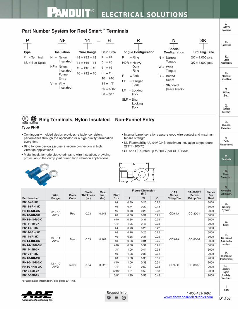
Part Number System for Reel Smart ™ Terminals
P NF 14 6 R N 3K
Type
P = Terminal
BS = Butt Splice
Insulation
N = Nylon Insulated
NF = Nylon Insulated Funnel Entry
V = VinylInsulated
SpecialConfiguration
N = Narrow Tongue
W = WideTongue
B = Butted Seam
= Standard(leave blank)
Wire Range
18 = #22 – 18
14 = #16 – 14
12 = #16 – 12
10 = #12 – 10
Std. Pkg. Size
2K = 2,000 pcs.
3K = 3,000 pcs.
—
Tongue Configuration
R = Ring
HDR = Heavy Duty Ring
F = Fork
FF = Fanged Fork
LF = Locking Fork
SLF = Short LockingFork
Stud Size
4 = #4
5 = #5
6 = #6
8 = #8
10 = #10
14 = 1/4"
56 = 5/16"
38 = 3/8"
Ring Terminals, Nylon Insulated – Non-Funnel Entry
• Continuously molded design provides reliable, consistentperformance through the applicator for a high quality terminationevery time
• Ring tongue design assures a secure connection in highvibration applications
• Metal insulation grip sleeve crimps to wire insulation, providingprotection to the crimp joint during high vibration applications
• Internal barrel serrations assure good wire contact and maximumtensile strength
• UL Flammability UL 94V-2/HB, maximum insulation temperature221°F (105°C)
• UL and CSA rated up to 600 V per UL 486A/B
C
L
W
Type PN-R
For applicator information, see page D1.143.
Part NumberWire
RangeColorCode
StockThickness
(In.)
Max.Ins.(In.)
StudSize
Figure Dimension (In.) CA9
SeriesCrimp Die
CA-800/EZ Series
Crimp Die
PiecesPer ReelL W C
PN18-4R-3K
22 – 18AWG Red 0.03 0.145
#4 0.80 0.25 0.22
CD9-1A CD-800-1
3000
PN18-6RN-3K #6 0.74 0.22 0.18 3000
PN18-6R-3K #6 0.78 0.25 0.22 3000
PN18-8R-3K #8 0.86 0.31 0.25 3000
PN18-10R-3K #10 0.86 0.31 0.25 3000
PN18-14R-3K 1/4" 1.05 0.45 0.38 3000
PN14-4R-3K
16 – 14AWG Blue 0.03 0.162
#4 0.76 0.25 0.22
CD9-2A CD-800-2
3000
PN14-6RN-3K #6 0.76 0.25 0.22 3000
PN14-6R-3K #6 0.86 0.31 0.25 3000
PN14-8R-3K #8 0.86 0.31 0.25 3000
PN14-10R-3K #10 0.86 0.31 0.25 3000
PN14-14R-3K 1/4" 1.06 0.44 0.38 3000
PN10-6R-2K
12 – 10AWG Yellow 0.04 0.225
#6 1.06 0.38 0.31
CD9-3B CD-800-3
2000
PN10-8R-2K #8 1.06 0.38 0.31 2000
PN10-10R-2K #10 1.06 0.38 0.31 2000
PN10-14R-2K 1/4" 1.21 0.52 0.38 2000
PN10-56R-2K 5/16" 1.21 0.52 0.38 2000
PN10-38R-2K 3/8" 1.29 0.58 0.43 2000
FWAHL
OpaqStan

FilNDUIr
E R.E.
ELECTRICAL SOLUTIONS
Order number of pieces required, in multiples of Standard Package Quantity. Prime items appear in BOLD.D1.104
B2.Cable
Accessories
C1.Wiring
Duct
C3.Abrasion
Protection
C4.Cable
Management
D1.Terminals
D2.Power
Connectors
E1.LabelingSystems
E2.Labels
E3.Pre-Printed & Write-On
Markers
F.Index
B3.StainlessSteel Ties
C2.Surface
Raceway
E5.Lockout/Tagout
& SafetySolutions
B1.Cable Ties
A.System
Overview
D3.GroundingConnectors
E4.Permanent
Identification
Ring Terminals, Nylon Insulated – Funnel Entry
• Continuously molded design provides reliable, consistentperformance through the applicator for a high quality terminationevery time
• Ring tongue design assures a secure connection in highvibration applications
• Metal insulation grip sleeve crimps to wire insulation, providingprotection to the crimp joint during high vibration applications
• Internal barrel serrations assure good wire contact and maximumtensile strength
• UL Flammability UL 94V-2/HB, maximum insulation temperature221°F (105°C)
• UL and CSA rated up to 600 V per UL 486A/B
C
L
W
Type PNF-R
For applicator information, see page D1.143.
Part NumberWire
RangeColorCode
Stock Thickness
(In.)
Max.Ins.(In.)
StudSize
Figure Dimensions (In.) CA9
SeriesCrimp Die
CA-800/EZ Series
Crimp Die
PiecesPer ReelL W C
PNF18-4RN-3K
22 – 18AWG Red 0.03 0.145
#4 0.74 0.22 0.19
CD9-1A CD-800-1
3000
PNF18-4R-3K #4 0.78 0.25 0.21 3000
PNF18-6RN-3K #6 0.74 0.22 0.16 3000
PNF18-6R-3K #6 0.78 0.25 0.21 3000
PNF18-8R-3K #8 0.86 0.31 0.25 3000
PNF18-10R-3K #10 0.86 0.31 0.25 3000
PNF18-14R-3K 1/4" 1.06 0.46 0.38 3000
PNF14-4R-3K
16 – 14AWG Blue 0.03 0.162
#4 0.78 0.25 0.18
CD9-2A CD-800-2
3000
PNF14-6RN-3K #6 0.78 0.25 0.18 3000
PNF14-6R-3K #6 0.87 0.31 0.24 3000
PNF14-8R-3K #8 0.87 0.31 0.25 3000
PNF14-10R-3K #10 0.85 0.31 0.29 3000
PNF14-14R-3K 1/4" 1.06 0.46 0.40 3000
PNF10-6R-2K
12 – 10AWG Yellow 0.04 0.225
#6 1.06 0.38 0.31
CD9-3B CD-800-3
2000
PNF10-8R-2K #8 1.06 0.38 0.31 2000
PNF10-10R-2K #10 1.06 0.38 0.31 2000
PNF10-14R-2K 1/4" 1.21 0.52 0.38 2000
PNF10-56R-2K 5/16" 1.21 0.52 0.38 2000
PNF10-38R-2K 3/8" 1.29 0.58 0.43 2000
FWAHL
OpaqStan

® LISTED CERTIFIED
® LISTED CERTIFIED
For technical assistance in the U.S., call 866-405-6654 (outside the U.S., see inside back cover for directory)
ELECTRICAL SOLUTIONS
D1.105
B2.Cable
Accessories
C1.Wiring
Duct
C3.Abrasion
Protection
C4.Cable
Management
D1.Terminals
D2.Power
Connectors
E1.LabelingSystems
E2.Labels
E3.Pre-Printed & Write-On
Markers
F.Index
B3.StainlessSteel Ties
C2.Surface
Raceway
E5.Lockout/Tagout
& SafetySolutions
B1.Cable Ties
A.System
Overview
D3.GroundingConnectors
E4.Permanent
Identification
Ring Terminals, Vinyl Insulated – Funnel Entry
• Continuously molded design provides reliable, consistentperformance through the applicator for a high quality terminationevery time
• Ring tongue design assures a secure connection in highvibration applications
• Insulation support helps to prevent wire damage inbending applications
• UL Flammability UL 94V-0, maximum insulation temperature221°F (105°C)
• UL and CSA rated up 600 V per UL 486A/B
C
L
W
Multiple Stud Ring Terminals, Vinyl Insulated – Funnel Entry
• Continuously molded design provides reliable, consistentperformance through the applicator for a high quality terminationevery time
• Teardrop shaped mounting hole of multiple stud terminals permitsuse with #6, #8, or #10 size studs
• Ring tongue design assures a secure connection in highvibration applications
• Insulation support helps to prevent wire damage inbending applications
• UL Flammability UL 94V-0, maximum insulation temperature221°F (105°C)
• UL and CSA rated up 600 V per UL 486A/B
C
W
L
Type PV-610RB
For applicator information, see page D1.143.
For applicator information, see page D1.143.
Type PV-RB
Part NumberWire
RangeColorCode
StockThickness
(In.)
Max.Ins.(In.)
StudSize
Figure Dimensions (In.)
CA9 Series
Crimp Die
CA-800/EZ Series
Crimp Die
PiecesPer ReelL W C
PV18-4RNB-3K
22 – 18AWG Red 0.03 0.150
#4 0.74 0.21 0.19
CD9-1A
CD-800-1
3000
PV18-4RB-3K #4 0.78 0.25 0.20 3000
PV18-6RNB-3K #6 0.75 0.23 0.19 3000
PV18-6RB-3K #6 0.78 0.25 0.20 3000
PV18-8RB-3K #8 0.86 0.31 0.25 3000
PV18-10RB-3K #10 0.86 0.31 0.25 3000
PV18-14RB-3K 1/4" 1.06 0.45 0.38 3000
PV18-56RB-2K 5/16" 1.06 0.46 0.38CD9-1B
2000
PV18-38RB-2K 3/8" 1.15 0.53 0.43 2000
PV14-4RB-3K
16 – 14AWG Blue 0.03 0.170
#4 0.76 0.25 0.22
CD9-2A
CD-800-2
3000
PV14-6RNB-3K #6 0.76 0.25 0.22 3000
PV14-6RB-3K #6 0.86 0.31 0.25 3000
PV14-8RB-3K #8 0.86 0.31 0.25 3000
PV14-10RB-3K #10 0.86 0.31 0.25 3000
PV14-14RB-3K 1/4" 1.05 0.45 0.38 3000
PV14-56RB-2K 5/16" 1.06 0.46 0.38CD9-2B
2000
PV14-38RB-2K 3/8" 1.15 0.53 0.43 2000
PV10-6RB-2K
12 – 10AWG Yellow 0.04 0.225
#6 1.02 0.31 0.31
CD9-3B CD-800-3
2000
PV10-8RB-2K #8 1.02 0.31 0.31 2000
PV10-10RB-2K #10 1.02 0.31 0.31 2000
PV10-14RB-2K 1/4" 1.20 0.52 0.38 2000
PV10-56RB-2K 5/16" 1.20 0.52 0.38 2000
PV10-38RB-2K 3/8" 1.23 0.58 0.38 2000
Part NumberWire
RangeColor Code
Stock Thickness
(In.)
Max.Ins.(In.)
Stud Size
Figure Dimensions (In.) CA9
Series Crimp Die
CA-800/EZ Series
Crimp Die
Pieces Per ReelL W C
PV18-610RB-3K 22 – 18 AWG Red 0.03 0.150#6,#8,#10
0.95 0.31 0.25 CD9-1A CD-800-1 3000
PV14-610RB-3K 16 – 14 AWG Blue 0.03 0.170 0.95 0.31 0.25 CD9-2A CD-800-2 3000
PV10-610RB-2K 12 – 10 AWG Yellow 0.04 0.225 1.17 0.37 0.31 CD9-3B CD-800-3 2000
FWAHL
OpaqStan
q.. 2 .. • Continuously molded design provides reliable, consistent
performance through the applicator for a high quality terminationevery time
• Manufactured from stock 56% thicker than a standard #16 – 14AWG terminal for use in heavy duty application
• Ring tongue design assures a secure connection in highvibration applications
• Metal insulation grip sleeve crimps to wire insulation, providingprotection to the crimp joint during high vibration applications
• Internal barrel serrations assure good wire contact and maximumtensile strength
• UL Flammability UL 94V-2/HB, maximum insulation temperature221°F (105°C)
• UL and CSA rated up to 600 V per UL 486A/B
C
L
W
ELECTRICAL SOLUTIONS
Order number of pieces required, in multiples of Standard Package Quantity. Prime items appear in BOLD.D1.106
B2.Cable
Accessories
C1.Wiring
Duct
C3.Abrasion
Protection
C4.Cable
Management
D1.Terminals
D2.Power
Connectors
E1.LabelingSystems
E2.Labels
E3.Pre-Printed & Write-On
Markers
F.Index
B3.StainlessSteel Ties
C2.Surface
Raceway
E5.Lockout/Tagout
& SafetySolutions
B1.Cable Ties
A.System
Overview
D3.GroundingConnectors
E4.Permanent
Identification
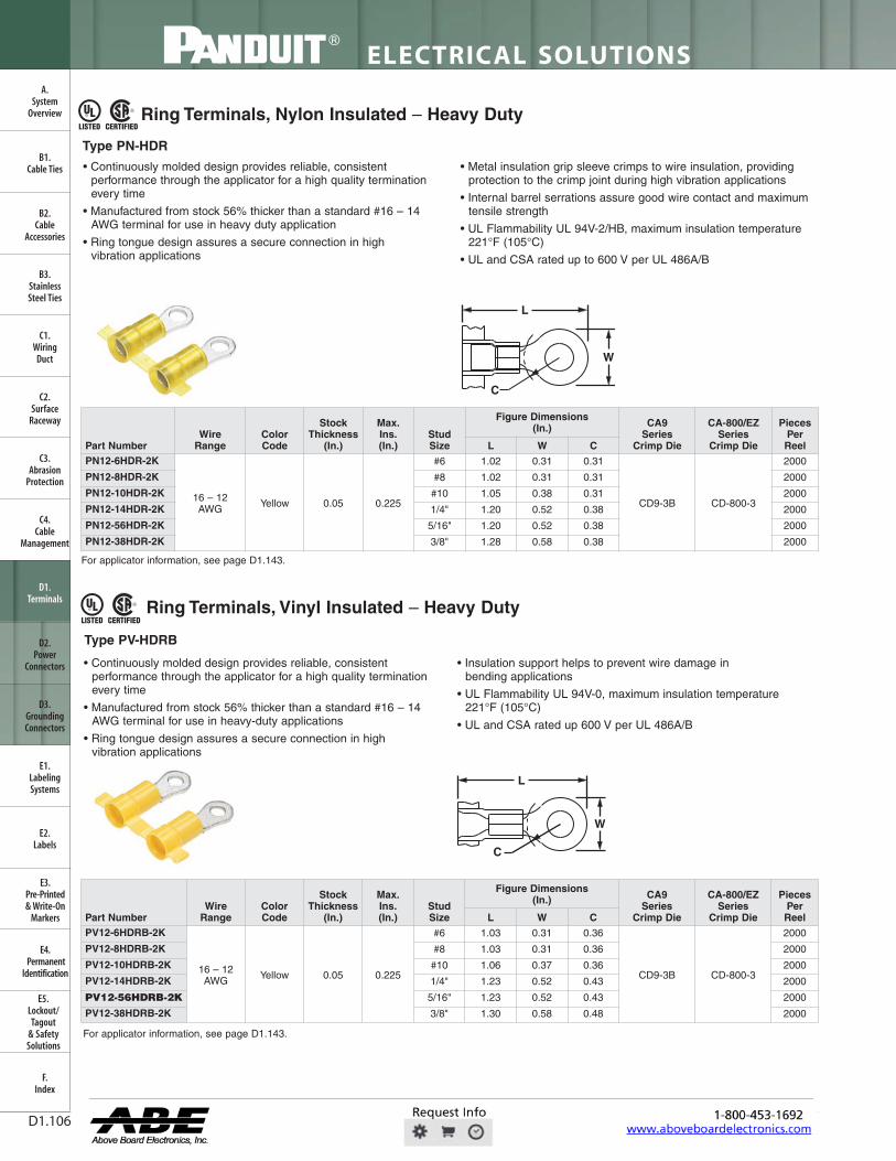
Ring Terminals, Nylon Insulated – Heavy Duty
Ring Terminals, Vinyl Insulated – Heavy Duty
• Continuously molded design provides reliable, consistentperformance through the applicator for a high quality terminationevery time
• Manufactured from stock 56% thicker than a standard #16 – 14AWG terminal for use in heavy-duty applications
• Ring tongue design assures a secure connection in highvibration applications
• Insulation support helps to prevent wire damage inbending applications
• UL Flammability UL 94V-0, maximum insulation temperature221°F (105°C)
• UL and CSA rated up 600 V per UL 486A/B
C
L
W
Type PN-HDR
Type PV-HDRB
For applicator information, see page D1.143.
For applicator information, see page D1.143.
Part NumberWire
RangeColor Code
Stock Thickness
(In.)
Max.Ins.(In.)
Stud Size
Figure Dimensions (In.) CA9
Series Crimp Die
CA-800/EZ Series
Crimp Die
Pieces Per ReelL W C
PN12-6HDR-2K
16 – 12AWG Yellow 0.05 0.225
#6 1.02 0.31 0.31
CD9-3B CD-800-3
2000
PN12-8HDR-2K #8 1.02 0.31 0.31 2000
PN12-10HDR-2K #10 1.05 0.38 0.31 2000
PN12-14HDR-2K 1/4" 1.20 0.52 0.38 2000
PN12-56HDR-2K 5/16" 1.20 0.52 0.38 2000
PN12-38HDR-2K 3/8" 1.28 0.58 0.38 2000
Part NumberWire
RangeColorCode
StockThickness
(In.)
Max.Ins.(In.)
StudSize
Figure Dimensions (In.) CA9
SeriesCrimp Die
CA-800/EZ Series
Crimp Die
PiecesPerReelL W C
PV12-6HDRB-2K
16 – 12AWG Yellow 0.05 0.225
#6 1.03 0.31 0.36
CD9-3B CD-800-3
2000
PV12-8HDRB-2K #8 1.03 0.31 0.36 2000
PV12-10HDRB-2K #10 1.06 0.37 0.36 2000
PV12-14HDRB-2K 1/4" 1.23 0.52 0.43 2000
PV12-56HDRB-2K 5/16" 1.23 0.52 0.43 2000
PV12-38HDRB-2K 3/8" 1.30 0.58 0.48 2000
FWAHL
OpaqStan

USTED CER11FIED
7
For technical assistance in the U.S., call 866-405-6654 (outside the U.S., see inside back cover for directory)
ELECTRICAL SOLUTIONS
D1.107
B2.Cable
Accessories
C1.Wiring
Duct
C3.Abrasion
Protection
C4.Cable
Management
D1.Terminals
D2.Power
Connectors
E1.LabelingSystems
E2.Labels
E3.Pre-Printed & Write-On
Markers
F.Index
B3.StainlessSteel Ties
C2.Surface
Raceway
E5.Lockout/Tagout
& SafetySolutions
B1.Cable Ties
A.System
Overview
D3.GroundingConnectors
E4.Permanent
Identification
Fork Terminals, Nylon Insulated – Non-Funnel Entry
• Continuously molded design provides reliable, consistentperformance through the applicator for a high quality terminationevery time
• Fork design provides for fast and easy installation, without theneed to remove fastener
• Metal insulation grip sleeve crimps to wire insulation, providingprotection to the crimp joint during high vibration applications
• Internal barrel serrations assure good wire contact and maximumtensile strength
• UL Flammability UL 94V-2/HB, maximum insulation temperature221°F (105°C)
• UL and CSA rated up to 600 V per UL 486A/B
For applicator information, see page D1.143.
C
L
W
Type PN-F
Part NumberWire
RangeColorCode
StockThickness
(In.)
Max.Ins.(In.)
StudSize
Figure Dimensions (In.) CA9
SeriesCrimp Die
CA-800/EZ Series
Crimp Die
PiecesPer ReelL W C
PN18-6FN-3K
22 – 18AWG Red 0.03 0.145
#6 0.78 0.25 0.20
CD9-1A CD-800-1
3000
PN18-6F-3K #6 0.78 0.30 0.20 3000
PN18-8F-3K #8 0.84 0.32 0.23 3000
PN18-10FN-3K #10 0.86 0.31 0.25 3000
PN18-10F-3K #10 0.86 0.35 0.25 3000
PN18-14F-3K 1/4" 1.03 0.44 0.33 3000
PN14-6FN-3K
16 – 14AWG Blue 0.03 0.162
#6 0.78 0.24 0.19
CD9-2A CD-800-2
3000
PN14-6F-3K #6 0.78 0.28 0.19 3000
PN14-8F-3K #8 0.84 0.31 0.23 3000
PN14-10FN-3K #10 0.86 0.31 0.24 3000
PN14-10F-3K #10 0.86 0.34 0.24 3000
PN14-14F-3K 1/4" 1.03 0.44 0.32 3000
PN10-6F-2K
12 – 10AWG Yellow 0.04 0.225
#6 1.00 0.31 0.24
CD9-3B CD-800-3
2000
PN10-8F-2K #8 1.03 0.37 0.24 2000
PN10-10F-2K #10 1.04 0.37 0.24 2000
PN10-14F-2K 1/4" 1.14 0.49 0.32 2000
FWAHL
OpaqStan

Pi%INUIT' AMI
J I
2 I
ELECTRICAL SOLUTIONS
Order number of pieces required, in multiples of Standard Package Quantity. Prime items appear in BOLD.D1.108
B2.Cable
Accessories
C1.Wiring
Duct
C3.Abrasion
Protection
C4.Cable
Management
D1.Terminals
D2.Power
Connectors
E1.LabelingSystems
E2.Labels
E3.Pre-Printed & Write-On
Markers
F.Index
B3.StainlessSteel Ties
C2.Surface
Raceway
E5.Lockout/Tagout
& SafetySolutions
B1.Cable Ties
A.System
Overview
D3.GroundingConnectors
E4.Permanent
Identification
Fork Terminals, Nylon Insulated – Funnel Entry
• Continuously molded design provides reliable, consistentperformance through the applicator for a high quality terminationevery time
• Fork design provides for fast and easy installation, without theneed to remove fastener
• Metal insulation grip sleeve crimps to wire insulation, providingprotection to the crimp joint during high vibration applications
• Internal barrel serrations assure good wire contact and maximumtensile strength
• UL Flammability UL 94V-2/HB, maximum insulation temperature221°F (105°C)
• UL and CSA rated up to 600 V per UL 486A/B
C
L
W
Type PNF-F
*Not UL Listed or CSA Certified.For applicator information, see page D1.143.
Part NumberWire
RangeColorCode
StockThickness
(In.)
Max.Ins.(In.)
StudSize
Figure Dimensions (In.) CA9
SeriesCrimp Die
CA-800/EZ Series
Crimp Die
PiecesPer ReelL W C
PNF18-6F-3K
22 – 18AWG Red 0.03 0.145
#6 0.77 0.24 0.19
CD9-1A CD-800-1
3000
PNF18-6FN-3K #6 0.78 0.30 0.19 3000
PNF18-8F-3K #8 0.83 0.32 0.22 3000
PNF18-10F-3K #10 0.85 0.35 0.24 3000
PNF18-14F-3K 1/4" 1.02 0.44 0.33 3000
PNF14-6FN-3K*
16 – 14AWG
Blue 0.03 0.162
#6 0.78 0.24 0.19
CD9-2A CD-800-2
3000
PNF14-6F-3K #6 0.78 0.28 0.19 3000
PNF14-8F-3K #8 0.84 0.31 0.23 3000
PNF14-10F-3K #10 0.86 0.34 0.24 3000
PNF14-14F-3K 1/4" 1.03 0.44 0.32 3000
PNF10-6F-2K12 – 10AWG Yellow 0.04 0.225
#6 1.01 0.31 0.24
CD9-3B CD-800-3
2000
PNF10-8F-2K #8 1.02 0.37 0.24 2000
PNF10-14F-2K 1/4" 1.13 0.49 0.32 2000
FWAHL
OpaqStan

® LISTED CERTIFIED
For technical assistance in the U.S., call 866-405-6654 (outside the U.S., see inside back cover for directory)
ELECTRICAL SOLUTIONS
D1.109
B2.Cable
Accessories
C1.Wiring
Duct
C3.Abrasion
Protection
C4.Cable
Management
D1.Terminals
D2.Power
Connectors
E1.LabelingSystems
E2.Labels
E3.Pre-Printed & Write-On
Markers
F.Index
B3.StainlessSteel Ties
C2.Surface
Raceway
E5.Lockout/Tagout
& SafetySolutions
B1.Cable Ties
A.System
Overview
D3.GroundingConnectors
E4.Permanent
Identification
Fork Terminals, Vinyl Insulated – Funnel Entry
• Continuously molded design provides reliable, consistentperformance through the applicator for a high quality terminationevery time
• Fork design provides for fast and easy installation, without theneed to remove fastener
• Insulation support helps to prevent wire damage inbending applications
• UL Flammability UL 94V-0, maximum insulation temperature221°F (105°C)
• UL and CSA rated up 600 V per UL 486A/B
*CSA Certified only.For applicator information, see page D1.143.
C
L
W
Type PV-FB
Part NumberWire
RangeColorCode
StockThickness
(In.)
Max.Ins.(In.)
StudSize
Figure Dimensions (In.) CA9
SeriesCrimp Die
CA-800/EZ Series
Crimp Die
PiecesPer ReelL W C
PV18-6FB-3K
22 – 18AWG Red 0.03 0.150
#6 0.78 0.25 0.20
CD9-1A CD-800-1
3000
PV18-6FNB-3K #6 0.78 0.30 0.20 3000
PV18-8FB-3K #8 0.84 0.32 0.23 3000
PV18-10FB-3K #10 0.86 0.35 0.25 3000
PV18-14FB-3K 1/4" 1.03 0.44 0.33 3000
PV14-6FB-3K
16 – 14AWG Blue 0.03 0.170
#6 0.78 0.24 0.19
CD9-2A CD-800-2
3000
PV14-6FNB-3K* #6 0.78 0.28 0.19 3000
PV14-8FB-3K #8 0.84 0.31 0.23 3000
PV14-10FB-3K #10 0.86 0.31 0.24 3000
PV14-10FNB-3K* #10 0.86 0.34 0.24 3000
PV14-14FB-3K 1/4" 1.03 0.44 0.32 3000
PV10-6FB-2K
12 – 10AWG Yellow 0.04 0.225
#6 0.99 0.31 0.22
CD9-3B CD-800-3
2000
PV10-8FB-2K #8 1.00 0.38 0.22 2000
PV10-10FB-2K #10 1.04 0.38 0.22 2000
PV10-14FB-2K 1/4" 1.13 0.49 0.32 2000
FWAHL
OpaqStan

Fi IN DUIr
e) . LISTED CERTIFIED
T
® @ . LISTED CERTIFIED
-f
ELECTRICAL SOLUTIONS
Order number of pieces required, in multiples of Standard Package Quantity. Prime items appear in BOLD.D1.110
B2.Cable
Accessories
C1.Wiring
Duct
C3.Abrasion
Protection
C4.Cable
Management
D1.Terminals
D2.Power
Connectors
E1.LabelingSystems
E2.Labels
E3.Pre-Printed & Write-On
Markers
F.Index
B3.StainlessSteel Ties
C2.Surface
Raceway
E5.Lockout/Tagout
& SafetySolutions
B1.Cable Ties
A.System
Overview
D3.GroundingConnectors
E4.Permanent
Identification
Locking Fork Terminals, Nylon Insulated – Non-Funnel Entry
• Continuously molded design provides reliable, consistentperformance through the applicator for a high quality terminationevery time
• Snap in place for secure connection
• Fork design provides for fast and easy installation, without theneed to remove fastener
• Metal insulation grip sleeve crimps to wire insulation, providingprotection to the crimp joint during high vibration applications
• Internal barrel serrations assure good wire contact and maximumtensile strength
• UL Flammability UL 94V-2/HB, maximum insulation temperature221°F (105°C)
• UL and CSA rated up to 600 V per UL 486A/B
C
L
W
Locking Fork Terminals, Nylon Insulated – Funnel Entry
• Continuously molded design provides reliable, consistentperformance through the applicator for a high quality terminationevery time
• Snap in place for secure connection
• Fork design provides for fast and easy installation, without theneed to remove fastener
• Metal insulation grip sleeve crimps to wire insulation, providingprotection to the crimp joint during high vibration applications
• Internal barrel serrations assure good wire contact and maximumtensile strength
• UL Flammability UL 94V-2/HB, maximum insulation temperature221°F (105°C)
• UL and CSA rated up to 600 V per UL 486A/B
For applicator information, see page D1.143.
C
L
W
Type PN-LF
Type PNF-LF
For applicator information, see page D1.143.
Part NumberWire
RangeColor Code
Stock Thickness
(In.)
Max.Ins.(In.)
Stud Size
Figure Dimensions (In.)
CA9 Series
Crimp Die
CA-800/EZ Series
Crimp Die
Pieces Per ReelL W C
PN18-6LF-3K22 – 18AWG Red 0.03 0.145
#6 0.82 0.27 0.19
CD9-1A CD-800-1
3000PN18-8LF-3K #8 0.89 0.29 0.23 3000PN18-10LF-3K #10 0.89 0.33 0.23 3000PN14-6LF-3K
16 – 14AWG Blue 0.03 0.162
#6 0.85 0.25 0.18
CD9-2A CD-800-2
3000PN14-8LF-3K #8 0.92 0.29 0.23 3000PN14-10LF-3K #10 0.92 0.33 0.23 3000PN10-6LF-2K
12 – 10AWG Yellow 0.04 0.225
#6 1.02 0.30 0.21
CD9-3B CD-800-3
2000PN10-8LF-2K #8 1.05 0.30 0.21 2000PN10-10LF-2K #10 1.05 0.34 0.21 2000
Part NumberWire
RangeColor Code
Stock Thickness
(In.)
Max.Ins.(In.)
Stud Size
Figure Dimensions(In.) CA9
Series Crimp Die
CA-800/EZ Series
Crimp Die
Pieces Per ReelL W C
PNF18-6LF-3K
22 – 18AWG Red 0.03 0.145
#6 0.85 0.27 0.19
CD9-1A CD-800-1
3000
PNF18-6LFW-3K #6 0.85 0.29 0.19 3000
PNF18-8LF-3K #8 0.89 0.29 0.23 3000
PNF18-10LF-3K #10 0.89 0.33 0.23 3000
PNF14-6LF-3K
16 – 14AWG Blue 0.03 0.162
#6 0.85 0.25 0.18
CD9-2A CD-800-2
3000
PNF14-8LF-3K #8 0.92 0.29 0.23 3000
PNF14-10LFN-3K #10 0.92 0.28 0.23 3000
PNF14-10LF-3K #10 0.92 0.33 0.23 3000
PNF10-6LF-2K
12 – 10AWG Yellow 0.04 0.225
#6 1.02 0.30 0.21
CD9-3B CD-800-3
2000
PNF10-8LF-2K #8 1.05 0.30 0.21 2000
PNF10-10LF-2K #10 1.05 0.34 0.21 2000
PNF10-14LF-2K 1/4" 1.19 0.46 0.32 2000
FWAHL
OpaqStan

® SA® LISTED CERTIFIED
For technical assistance in the U.S., call 866-405-6654 (outside the U.S., see inside back cover for directory)
ELECTRICAL SOLUTIONS
D1.111
B2.Cable
Accessories
C1.Wiring
Duct
C3.Abrasion
Protection
C4.Cable
Management
D1.Terminals
D2.Power
Connectors
E1.LabelingSystems
E2.Labels
E3.Pre-Printed & Write-On
Markers
F.Index
B3.StainlessSteel Ties
C2.Surface
Raceway
E5.Lockout/Tagout
& SafetySolutions
B1.Cable Ties
A.System
Overview
D3.GroundingConnectors
E4.Permanent
Identification
Locking Fork Terminals, Vinyl Insulated – Funnel Entry
• Continuously molded design provides reliable, consistentperformance through the applicator for a high quality terminationevery time
• Snap in place for secure connection
• Fork design provides for fast and easy installation, without theneed to remove fastener
• Insulation support helps to prevent wire damage inbending applications
• UL Flammability UL 94V-0, maximum insulation temperature221°F (105°C)
• UL and CSA rated to 600 V per UL 486A/B
*Not UL Listed or CSA Certified.For applicator information, see page D1.143.
C
L
W
Type PV-LFB
Part NumberWire
RangeColor Code
Stock Thickness
(In.)
Max.Ins.(In.)
Stud Size
Figure Dimensions (In.) CA9
Series Crimp Die
CA-800/EZ Series
Crimp Die
Pieces Per ReelL W C
PV18-6LFB-3K
22 – 18AWG Red 0.03 0.150
#6 0.80 0.27 0.19
CD9-1A CD-800-1
3000
PV18-6LFWB-3K #6 0.83 0.29 0.19 3000
PV18-8LFB-3K #8 0.87 0.29 0.23 3000
PV18-10LFNB-3K* #10 0.87 0.29 0.23 3000
PV18-10LFB-3K #10 0.87 0.33 0.23 3000
PV14-6LFB-3K
16 – 14AWG Blue 0.03 0.170
#6 0.85 0.25 0.18
CD9-2A CD-800-2
3000
PV14-6LFWB-3K #6 0.85 0.29 0.18 3000
PV14-8LFB-3K #8 0.92 0.29 0.23 3000
PV14-10LFB-3K #10 0.92 0.33 0.23 3000
PV10-6LFB-2K
12 – 10AWG Yellow 0.04 0.225
#6 1.02 0.30 0.21
CD9-3B CD-800-3
2000
PV10-8LFB-2K #8 1.04 0.30 0.21 2000
PV10-10LFB-2K #10 1.04 0.34 0.21 2000
PV10-14LFB-2K 1/4" 1.16 0.46 0.32 2000
FWAHL
OpaqStan

1
A
-f
® SA® LISTED CERTIFIED
LISTED CERTIFIED
I
,
ELECTRICAL SOLUTIONS
Order number of pieces required, in multiples of Standard Package Quantity. Prime items appear in BOLD.D1.112
B2.Cable
Accessories
C1.Wiring
Duct
C3.Abrasion
Protection
C4.Cable
Management
D1.Terminals
D2.Power
Connectors
E1.LabelingSystems
E2.Labels
E3.Pre-Printed & Write-On
Markers
F.Index
B3.StainlessSteel Ties
C2.Surface
Raceway
E5.Lockout/Tagout
& SafetySolutions
B1.Cable Ties
A.System
Overview
D3.GroundingConnectors
E4.Permanent
Identification
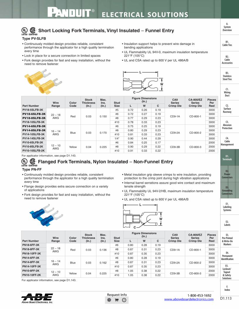
Short Locking Fork Terminals, Nylon Insulated – Non-Funnel Entry
• Continuously molded design provides reliable, consistentperformance through the applicator for a high quality terminationevery time
• Lock in place for a secure connection in limited spaces
• Fork design provides for fast and easy installation, without theneed to remove fastener
• Metal insulation grip sleeve crimps to wire insulation, providingprotection to the crimp joint during high vibration applications
• Internal barrel serrations assure good wire contact and maximumtensile strength
• UL Flammability UL 94V-2/HB, maximum insulation temperature221°F (105°C)
• UL and CSA rated up to 600 V per UL 486A/B
C
L
W
Short Locking Fork Terminals, Nylon Insulated – Funnel Entry
• Continuously molded design provides reliable, consistentperformance through the applicator for a high quality terminationevery time
• Lock in place for a secure connection in limited spaces
• Fork design provides for fast and easy installation, without theneed to remove fastener
• Metal insulation grip sleeve crimps to wire insulation, providingprotection to the crimp joint during high vibration applications
• Internal barrel serrations assure good wire contact and maximumtensile strength
• UL Flammability UL 94V-2/HB, maximum insulation temperature221°F (105°C)
• UL and CSA rated up to 600 V per UL 486A/B
C
W
L
Type PN-SLF
Type PNF-SLF
For applicator information, see page D1.143.
For applicator information, see page D1.143.
Part NumberWire
RangeColor Code
Stock Thickness
(In.)
Max.Ins.(In.)
Stud Size
Figure Dimensions (In.)
CA9 Series
Crimp Die
CA-800/EZ Series
Crimp Die
Pieces Per ReelL W C
PN18-5SLF-3K
22 – 18AWG Red 0.03 0.145
#5 0.75 0.26 0.19
CD9-1A CD-800-1
3000PN18-6SLF-3K #6 0.75 0.27 0.19 3000PN18-8SLF-3K #8 0.79 0.29 0.23 3000PN18-10SLF-3K #10 0.80 0.33 0.23 3000PN14-5SLF-3K
16 – 14AWG Blue 0.03 0.162
#5 0.75 0.25 0.19
CD9-2A CD-800-2
3000PN14-6SLF-3K #6 0.75 0.25 0.19 3000PN14-8SLF-3K #8 0.80 0.29 0.23 3000PN14-10SLF-3K #10 0.81 0.33 0.23 3000PN10-8SLF-2K 12 – 10
AWG Yellow 0.04 0.225#8 0.92 0.29 0.22
CD9-3B CD-800-32000
PN10-10SLF-2K #10 0.92 0.33 0.22 2000
Part NumberWire
RangeColor Code
Stock Thickness
(In.)
Max.Ins.(In.)
Stud Size
Figure Dimensions (In.) CA9
Series Crimp Die
CA-800/EZ Series
Crimp Die
Pieces Per ReelL W C
PNF18-5SLF-3K
22 – 18AWG Red 0.03 0.145
#5 0.73 0.26 0.19
CD9-1A CD-800-1
3000
PNF18-6SLF-3K #6 0.74 0.27 0.19 3000
PNF18-8SLF-3K #8 0.80 0.29 0.23 3000
PNF18-10SLF-3K #10 0.80 0.33 0.23 3000
PNF14-6SLF-3K 16 – 14AWG Blue 0.03 0.162
#6 0.75 0.25 0.19CD9-2A CD-800-2
3000
PNF14-10SLF-3K #10 0.81 0.33 0.23 3000
PNF10-6SLF-2K12 – 10AWG Yellow 0.04 0.225
#6 0.91 0.25 0.17
CD9-3B CD-800-3
2000PNF10-8SLF-2K #8 0.92 0.29 0.22 2000
PNF10-10SLF-2K #10 0.93 0.33 0.22 2000
FWAHL
OpaqStan
71
11-voco,
1 -f
® LISTED CERTIFIED
0 LISTED CERTIFIED
7
For technical assistance in the U.S., call 866-405-6654 (outside the U.S., see inside back cover for directory)
ELECTRICAL SOLUTIONS
D1.113
Short Locking Fork Terminals, Vinyl Insulated – Funnel Entry
• Continuously molded design provides reliable, consistentperformance through the applicator for a high quality terminationevery time
• Lock in place for a secure connection in limited spaces
• Fork design provides for fast and easy installation, without theneed to remove fastener
• Insulation support helps to prevent wire damage inbending applications
• UL Flammability UL 94V-0, maximum insulation temperature221°F (105°C)
• UL and CSA rated up to 600 V per UL 486A/B
Flanged Fork Terminals, Nylon Insulated – Non-Funnel Entry
• Continuously molded design provides reliable, consistentperformance through the applicator for a high quality terminationevery time
• Flange design provides extra secure connection on a varietyof applications
• Fork design provides for fast and easy installation, without theneed to remove fastener
• Metal insulation grip sleeve crimps to wire insulation, providingprotection to the crimp joint during high vibration applications
• Internal barrel serrations assure good wire contact and maximumtensile strength
• UL Flammability UL 94V-2/HB, maximum insulation temperature221°F (105°C)
• UL and CSA rated up to 600 V per UL 486A/B
C
L
W
C
L
W
B2.Cable
Accessories
C1.Wiring
Duct
C3.Abrasion
Protection
C4.Cable
Management
D1.Terminals
D2.Power
Connectors
E1.LabelingSystems
E2.Labels
E3.Pre-Printed & Write-On
Markers
F.Index
B3.StainlessSteel Ties
C2.Surface
Raceway
E5.Lockout/Tagout
& SafetySolutions
B1.Cable Ties
A.System
Overview
D3.GroundingConnectors
E4.Permanent
Identification
Type PV-SLFB
Type PN-FF
For applicator information, see page D1.143.
For applicator information, see page D1.143.
Part NumberWire
RangeColor Code
Stock Thickness
(In.)
Max.Ins.(In.)
Stud Size
Figure Dimensions (In.) CA9
Series Crimp Die
CA-800/EZ Series
Crimp Die
Pieces Per ReelL W C
PV18-5SLFB-3K
22 – 18AWG Red 0.03 0.150
#5 0.72 0.26 0.19
CD9-1A CD-800-1
3000
PV18-6SLFB-3K #6 0.72 0.27 0.19 3000
PV18-8SLFB-3K #8 0.77 0.29 0.23 3000
PV18-10SLFB-3K #10 0.78 0.33 0.23 3000
PV14-6SLFB-3K
16 – 14AWG Blue 0.03 0.170
#6 0.75 0.25 0.19
CD9-2A CD-800-2
3000
PV14-8SLFB-3K #8 0.80 0.29 0.23 3000
PV14-10SLFB-3K #10 0.81 0.33 0.23 3000
PV14-14SLFB-3K 1/4" 0.90 0.44 0.29 3000
PV10-6SLFB-2K12 – 10AWG Yellow 0.04 0.225
#6 0.84 0.25 0.17
CD9-3B CD-800-3
2000
PV10-8SLFB-2K #8 0.90 0.29 0.22 2000
PV10-10SLFB-2K #10 0.91 0.33 0.22 2000
Part NumberWire
RangeColor Code
Stock Thickness
(In.)
Max.Ins.(In.)
Stud Size
Figure Dimensions (In.) CA9
Series Crimp Die
CA-800/EZ Series
Crimp Die
Pieces Per ReelL W C
PN18-6FF-3K22 – 18AWG Red 0.03 0.136
#6 0.80 0.28 0.19
CD9-1A CD-800-1
3000
PN18-8FF-3K #8 0.87 0.31 0.23 3000
PN18-10FF-3K #10 0.87 0.35 0.23 3000
PN14-6FF-3K16 – 14AWG Blue 0.03 0.162
#6 0.80 0.28 0.19
CD9-2A CD-800-2
3000
PN14-8FF-3K #8 0.87 0.31 0.23 3000
PN14-10FF-3K #10 0.87 0.35 0.23 3000
PN10-8FF-2K 12 – 10AWG Yellow 0.04 0.225
#8 1.05 0.38 0.22CD9-3B CD-800-3
2000
PN10-10FF-2K #10 1.05 0.38 0.22 2000
FWAHL
OpaqStan

J
LISTED CERTIFIED
-f A
® SA® LISTED CERTIFIED
I
1
ELECTRICAL SOLUTIONS
Order number of pieces required, in multiples of Standard Package Quantity. Prime items appear in BOLD.D1.114
B2.Cable
Accessories
C1.Wiring
Duct
C3.Abrasion
Protection
C4.Cable
Management
D1.Terminals
D2.Power
Connectors
E1.LabelingSystems
E2.Labels
E3.Pre-Printed & Write-On
Markers
F.Index
B3.StainlessSteel Ties
C2.Surface
Raceway
E5.Lockout/Tagout
& SafetySolutions
B1.Cable Ties
A.System
Overview
D3.GroundingConnectors
E4.Permanent
Identification
Flanged Fork Terminals, Nylon Insulated – Funnel Entry
• Continuously molded design provides reliable, consistentperformance through the applicator for a high quality terminationevery time
• Flange design provides extra secure connection on a varietyof applications
• Fork design provides for fast and easy installation, without theneed to remove fastener
• Metal insulation grip sleeve crimps to wire insulation, providingprotection to the crimp joint during high vibration applications
• Internal barrel serrations assure good wire contact and maximumtensile strength
• UL Flammability UL 94V-2/HB, maximum insulation temperature221°F (105°C)
• UL and CSA rated up to 600 V per UL 486A/B
Flanged Fork Terminals, Vinyl Insulated – Funnel Entry
• Continuously molded design provides reliable, consistentperformance through the applicator for a high quality terminationevery time
• Flange design provides extra secure connection on a varietyof applications
• Fork design provides for fast and easy installation, without theneed to remove fastener
• Insulation support helps to prevent wire damage inbending applications
• UL Flammability UL 94V-0, maximum insulation temperature221°F (105°C)
• UL and CSA rated up 600 V per UL 486A/B
C
L
W
C
L
W
Type PNF-FF
Type PV-FFB
For applicator information, see page D1.143.
For applicator information, see page D1.143.
Part NumberWire
RangeColor Code
Stock Thickness
(In.)
Max.Ins.(In.)
Stud Size
Figure Dimensions (In.) CA9
Series Crimp Die
CA-800/EZ Series
Crimp Die
Pieces Per ReelL W C
PNF18-6FF-3K22 – 18AWG Red 0.03 0.145
#6 0.80 0.28 0.19
CD9-1A CD-800-1
3000
PNF18-8FF-3K #8 0.87 0.31 0.23 3000
PNF18-10FF-3K #10 0.86 0.35 0.23 3000
PNF14-6FF-3K16 – 14AWG Blue 0.03 0.162
#6 0.80 0.28 0.19
CD9-2A CD-800-2
3000
PNF14-8FF-3K #8 0.87 0.31 0.23 3000
PNF14-10FF-3K #10 0.87 0.35 0.23 3000
PNF10-8FF-2K 12 – 10AWG Yellow 0.04 0.225
#8 1.05 0.38 0.24CD9-3B CD-800-3
2000
PNF10-10FF-2K #10 1.05 0.38 0.24 2000
Part NumberWire
RangeColor Code
Stock Thickness
(In.)
Max.Ins.(In.)
Stud Size
Figure Dimensions (In.) CA9
Series Crimp Die
CA-800/EZ Series
Crimp Die
Pieces Per ReelL W C
PV18-6FFB-3K22 – 18AWG Red 0.03 0.150
#6 0.80 0.28 0.19
CD9-1A CD-800-1
3000
PV18-8FFB-3K #8 0.87 0.31 0.23 3000
PV18-10FFB-3K #10 0.86 0.35 0.23 3000
PV14-6FFB-3K16 – 14AWG Blue 0.03 0.170
#6 0.80 0.28 0.19
CD9-2A CD-800-2
3000
PV14-8FFB-3K #8 0.86 0.31 0.23 3000
PV14-10FFB-3K #10 0.86 0.35 0.23 3000
PV10-8FFB-2K 12 – 10AWG Yellow 0.04 0.225
#8 1.03 0.37 0.22CD9-3B CD-800-3
2000
PV10-10FFB-2K #10 1.03 0.37 0.22 2000
FWAHL
OpaqStan
T T T T T -7
® ® USTED CERTIFIED USTED CERTIFIED
For technical assistance in the U.S., call 866-405-6654 (outside the U.S., see inside back cover for directory)
ELECTRICAL SOLUTIONS
D1.115
B2.Cable
Accessories
C1.Wiring
Duct
C3.Abrasion
Protection
C4.Cable
Management
D1.Terminals
D2.Power
Connectors
E1.LabelingSystems
E2.Labels
E3.Pre-Printed & Write-On
Markers
F.Index
B3.StainlessSteel Ties
C2.Surface
Raceway
E5.Lockout/Tagout
& SafetySolutions
B1.Cable Ties
A.System
Overview
D3.GroundingConnectors
E4.Permanent
Identification
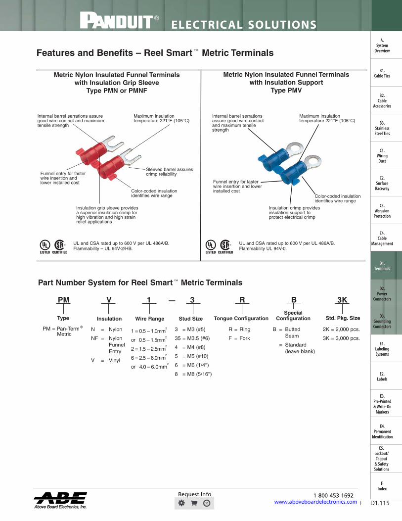
Features and Benefits – Reel Smart ™ Metric Terminals
Metric Nylon Insulated Funnel Terminalswith Insulation Grip Sleeve
Type PMN or PMNF
Metric Nylon Insulated Funnel Terminalswith Insulation Support
Type PMV
Color-coded insulationidentifies wire range
Insulation crimp providesinsulation support toprotect electrical crimp
Internal barrel serrationsassure good wire contactand maximum tensilestrength
Maximum insulationtemperature 221°F (105°C)
Funnel entry for fasterwire insertion andlower installed cost
Sleeved barrel assurescrimp reliability
Color-coded insulationidentifies wire range
Internal barrel serrations assuregood wire contact and maximumtensile strength
Maximum insulationtemperature 221°F (105°C)
Funnel entry for fasterwire insertion and lowerinstalled cost
Insulation grip sleeve providesa superior insulation crimp forhigh vibration and high strainrelief applications
Part Number System for Reel Smart ™ Metric Terminals
PM V 1 3 R B 3K
Type
PM = Pan-Term ®
MetricN = Nylon
NF = Nylon FunnelEntry
V = Vinyl
B = Butted Seam
= Standard(leave blank)
1 = 0.5 – 1.0mm2
or 0.5 – 1.5mm2
2 = 1.5 – 2.5mm2
6 = 2.5 – 6.0mm2
or 4.0 – 6.0mm2
2K = 2,000 pcs.
3K = 3,000 pcs.
Stud Size Tongue Configuration
—
R = Ring
F = Fork
SpecialConfigurationInsulation Wire Range Std. Pkg. Size
3 = M3 (#5)
35 = M3.5 (#6)
4 = M4 (#8)
5 = M5 (#10)
6 = M6 (1/4'')
8 = M8 (5/16'')
UL and CSA rated up to 600 V per UL 486A/B.Flammability – UL 94V-2/HB.
UL and CSA rated up to 600 V per UL 486A/B.Flammability UL 94V-0.
FWAHL
OpaqStan

FilNDUIr
2 CERnFlED
ELECTRICAL SOLUTIONS
Order number of pieces required, in multiples of Standard Package Quantity. Prime items appear in BOLD.D1.116
B2.Cable
Accessories
C1.Wiring
Duct
C3.Abrasion
Protection
C4.Cable
Management
D1.Terminals
D2.Power
Connectors
E1.LabelingSystems
E2.Labels
E3.Pre-Printed & Write-On
Markers
F.Index
B3.StainlessSteel Ties
C2.Surface
Raceway
E5.Lockout/Tagout
& SafetySolutions
B1.Cable Ties
A.System
Overview
D3.GroundingConnectors
E4.Permanent
Identification
Metric Ring Terminals, Nylon Insulated – Non-Funnel Entry
• Continuously molded design provides reliable, consistentperformance through the applicator for a high quality terminationevery time
• Ring tongue design assures a secure connection in highvibration applications
• Metal insulation grip sleeve crimps to wire insulation, providingprotection to the crimp joint during high vibration applications
• Internal barrel serrations assure good wire contact and maximumtensile strength
• UL Flammability UL 94V-2/HB, maximum insulation temperature221°F (105°C)
• UL and CSA rated up to 600 V per UL 486A/B
C
L
W
Type PMN-R
For applicator information, see page D1.143.
Part Number
Wire Range(mm2)
Color Code
Max.Ins.
(mm)Stud Size
Figure Dimensions (mm) CA9
Series Crimp Die
CA-800/EZ Series
Crimp Die
Pieces Per ReelL W C
PMN1-3R-3K
0.5 – 1.0 Red 3.7
M3 19.3 5.8 5.2
CD9-1A CD-800-1
3000
PMN1-35R-3K M3.5 19.3 5.8 5.2 3000
PMN1-4R-3K M4 21.9 7.9 6.4 3000
PMN1-5R-3K M5 22.4 8.9 6.4 3000
PMN1-6R-3K M6 26.7 10.9 9.7 3000
PMN2-3R-3K
1.5 – 2.5 Blue 4.1
M3 21.6 5.8 5.1
CD9-2A CD-800-2
3000
PMN2-35R-3K M3.5 21.6 5.8 5.1 3000
PMN2-4R-3K M4 24.1 7.9 6.5 3000
PMN2-5R-3K M5 24.6 8.9 6.5 3000
PMN2-6R-3K M6 26.7 10.9 9.7 3000
PMN6-3R-2K
4.0 – 6.0 Yellow 5.7
M3 24.7 5.8 7.9
CD9-3B CD-800-3
2000
PMN6-35R-2K M3.5 24.7 5.8 7.9 2000
PMN6-4R-2K M4 25.7 7.9 7.9 2000
PMN6-5R-2K M5 26.4 9.7 7.9 2000
PMN6-6R-2K M6 29.0 10.9 9.7 2000
PMN6-8R-2K M8 30.0 13.2 9.7 2000
FWAHL
OpaqStan
USTED CER11FIED
For technical assistance in the U.S., call 866-405-6654 (outside the U.S., see inside back cover for directory)
ELECTRICAL SOLUTIONS
D1.117
B2.Cable
Accessories
C1.Wiring
Duct
C3.Abrasion
Protection
C4.Cable
Management
D1.Terminals
D2.Power
Connectors
E1.LabelingSystems
E2.Labels
E3.Pre-Printed & Write-On
Markers
F.Index
B3.StainlessSteel Ties
C2.Surface
Raceway
E5.Lockout/Tagout
& SafetySolutions
B1.Cable Ties
A.System
Overview
D3.GroundingConnectors
E4.Permanent
Identification
Metric Ring Terminals, Nylon Insulated – Funnel Entry
• Continuously molded design provides reliable, consistentperformance through the applicator for a high quality terminationevery time
• Ring tongue design assures a secure connection in highvibration applications
• Metal insulation grip sleeve crimps to wire insulation, providingprotection to the crimp joint during high vibration applications
• Internal barrel serrations assure good wire contact and maximumtensile strength
• UL Flammability UL 94V-2/HB, maximum insulation temperature221°F (105°C)
• UL and CSA rated up to 600 V per UL 486A/B
C
L
W
Type PMNF-R
For applicator information, see page D1.143.
Part Number
Wire Range(mm2)
Color Code
Max.Ins.
(mm)Stud Size
Figure Dimensions (mm) CA9
Series Crimp Die
CA-800/EZ Series
Crimp Die
Pieces Per ReelL W C
PMNF1-3R-3K
0.5 – 1.0 Red 3.7
M3 19.3 5.8 5.2
CD9-1A CD-800-1
3000
PMNF1-35R-3K M3.5 19.3 5.8 5.2 3000
PMNF1-4R-3K M4 21.9 7.9 6.4 3000
PMNF1-5R-3K M5 22.4 8.9 6.4 3000
PMNF1-6R-3K M6 26.7 10.9 9.7 3000
PMNF2-3R-3K
1.5 – 2.5 Blue 4.1
M3 19.4 5.8 5.1
CD9-2A CD-800-2
3000
PMNF2-35R-3K M3.5 19.4 5.8 5.1 3000
PMNF2-4R-3K M4 21.8 7.9 6.5 3000
PMNF2-5R-3K M5 22.4 8.9 6.5 3000
PMNF2-6R-3K M6 26.5 10.9 9.7 3000
PMNF6-3R-2K
4.0 – 6.0 Yellow 5.7
M3 24.7 5.8 7.9
CD9-3B CD-800-3
2000
PMNF6-35R-2K M3.5 24.7 5.8 7.9 2000
PMNF6-4R-2K M4 25.7 7.9 7.9 2000
PMNF6-5R-2K M5 26.4 9.7 7.9 2000
PMNF6-6R-2K M6 29.0 10.9 9.7 2000
PMNF6-8R-2K M8 30.0 13.2 9.7 2000
FWAHL
OpaqStan

® SA® LISTED CERTIFIED
L
ELECTRICAL SOLUTIONS
Order number of pieces required, in multiples of Standard Package Quantity. Prime items appear in BOLD.D1.118
B2.Cable
Accessories
C1.Wiring
Duct
C3.Abrasion
Protection
C4.Cable
Management
D1.Terminals
D2.Power
Connectors
E1.LabelingSystems
E2.Labels
E3.Pre-Printed & Write-On
Markers
F.Index
B3.StainlessSteel Ties
C2.Surface
Raceway
E5.Lockout/Tagout
& SafetySolutions
B1.Cable Ties
A.System
Overview
D3.GroundingConnectors
E4.Permanent
Identification
Metric Ring Terminals, Vinyl Insulated – Funnel Entry
• Continuously molded design provides reliable, consistentperformance through the applicator for a high quality terminationevery time
• Insulation support helps to prevent wire damage inbending applications
• Ring tongue design assures a secure connection in highvibration applications
• UL Flammability UL 94V-0, maximum insulation temperature221°F (105°C)
• UL and CSA rated up to 600 V per UL 486A/B
C
L
W
Type PMV-RB
For applicator information, see page D1.143.
Part Number
Wire Range(mm2)
Color Code
Max.Ins.
(mm)Stud Size
Figure Dimensions (mm) CA9
Series Crimp Die
CA-800/EZ Series
Crimp Die
Pieces Per ReelL W C
PMV1-3RB-3K
0.5 – 1.0 Red 3.7
M3 19.3 5.8 5.2
CD9-1A CD-800-1
3000
PMV1-35RB-3K M3.5 19.3 5.8 5.2 3000
PMV1-4RB-3K M4 21.8 7.9 6.4 3000
PMV1-5RB-3K M5 22.4 8.9 6.4 3000
PMV1-6RB-3K M6 26.4 10.9 9.7 3000
PMV2-3RB-3K
1.5 – 2.5 Blue 4.3
M3 21.3 5.8 5.1
CD9-2A CD-800-2
3000
PMV2-35RB-3K M3.5 21.3 5.8 5.1 3000
PMV2-4RB-3K M4 23.9 7.9 6.5 3000
PMV2-5RB-3K M5 24.4 8.9 6.5 3000
PMV2-6RB-3K M6 26.7 10.9 9.7 3000
PMV6-3RB-2K
4.0 – 6.0 Yellow 5.7
M3 24.9 6.1 7.9
CD9-3B CD-800-3
2000
PMV6-35RB-2K M3.5 24.9 6.1 7.9 2000
PMV6-4RB-2K M4 25.9 7.9 7.9 2000
PMV6-5RB-2K M5 26.7 9.4 7.9 2000
PMV6-6RB-2K M6 29.2 10.9 9.7 2000
PMV6-8RB-2K M8 30.5 13.2 9.7 2000
FWAHL
OpaqStan

7 A
LISTED CERTIFIED
7 A
MN =
LISTED CERTIFIED
For technical assistance in the U.S., call 866-405-6654 (outside the U.S., see inside back cover for directory)
ELECTRICAL SOLUTIONS
D1.119
B2.Cable
Accessories
C1.Wiring
Duct
C3.Abrasion
Protection
C4.Cable
Management
D1.Terminals
D2.Power
Connectors
E1.LabelingSystems
E2.Labels
E3.Pre-Printed & Write-On
Markers
F.Index
B3.StainlessSteel Ties
C2.Surface
Raceway
E5.Lockout/Tagout
& SafetySolutions
B1.Cable Ties
A.System
Overview
D3.GroundingConnectors
E4.Permanent
Identification
Metric Fork Terminals, Nylon Insulated – Non-Funnel Entry
• Continuously molded design provides reliable, consistentperformance through the applicator for a high quality terminationevery time
• Fork design provides for fast and easy installation, without theneed to remove fastener
• Metal insulation grip sleeve crimps to wire insulation, providingprotection to the crimp joint during high vibration applications
• Internal barrel serrations assure good wire contact and maximumtensile strength
• UL Flammability UL 94V-2/HB, maximum insulation temperature221°F (105°C)
• UL and CSA rated up to 600 V per UL 486A/B
C
L
W
Metric Fork Terminals, Nylon Insulated – Funnel Entry
• Continuously molded design provides reliable, consistentperformance through the applicator for a high quality terminationevery time
• Flange design provides extra secure connection on a varietyof applications
• Fork design provides for fast and easy installation, without theneed to remove fastener
• Metal insulation grip sleeve crimps to wire insulation, providingprotection to the crimp joint during high vibration applications
• Internal barrel serrations assure good wire contact and maximumtensile strength
• UL Flammability UL 94V-2/HB, maximum insulation temperature221°F (105°C)
• UL and CSA rated up to 600 V per UL 486A/B
C
L
W
Type PMN-F
Type PMNF-F
For applicator information, see page D1.143.
For applicator information, see page D1.143.
Part Number
Wire Range(mm2)
Color Code
Max.Ins.
(mm)Stud Size
Figure Dimensions (mm) CA9
Series Crimp Die
CA-800/EZ Series
Crimp Die
Pieces Per ReelL W C
PMN1-3F-3K
0.5 – 1.0 Red 3.7
M3 19.9 5.9 5.0
CD9-1A CD-800-1
3000PMN1-4F-3K M4 21.6 8.2 5.8 3000PMN1-5F-3K M5 21.8 8.9 6.3 3000PMN1-6F-3K M6 26.4 11.2 8.4 3000PMN2-3F-3K
1.5 – 2.5 Blue 4.1
M3 19.8 5.9 5.1
CD9-2A CD-800-2
3000PMN2-4F-3K M4 21.3 7.9 5.9 3000PMN2-5F-3K M5 21.9 8.6 6.4 3000PMN2-6F-3K M6 26.2 11.2 8.5 3000PMN6-4F-2K
4.0 – 6.0 Yellow 5.7
M4 25.7 7.9 6.1
CD9-3B CD-800-3
2000PMN6-5F-2K M5 25.7 9.5 6.1 2000PMN6-6F-2K M6 28.5 11.0 8.2 2000
Part Number
Wire Range(mm2)
Color Code
Max.Ins.
(mm)Stud Size
Figure Dimensions (mm) CA9
Series Crimp Die
CA-800/EZ Series
Crimp Die
Pieces Per ReelL W C
PMNF1-3F-3K
0.5 – 1.0 Red 3.7
M3 20.0 5.9 5.0
CD9-1A CD-800-1
3000PMNF1-4F-3K M4 21.6 8.2 5.8 3000PMNF1-5F-3K M5 21.8 8.9 6.3 3000PMNF1-6F-3K M6 26.4 11.2 8.4 3000PMNF2-3F-3K
1.5 – 2.5 Blue 4.1
M3 19.8 5.9 5.1
CD9-2A CD-800-2
3000PMNF2-4F-3K M4 21.3 7.9 5.9 3000PMNF2-5F-3K M5 21.9 8.6 6.4 3000PMNF2-6F-3K M6 26.2 11.2 8.5 3000PMNF6-4F-2K
4.0 – 6.0 Yellow 5.7
M4 25.7 7.9 6.1
CD9-3B CD-800-3
2000PMNF6-5F-2K M5 25.7 9.5 6.1 2000PMNF6-6F-2K M6 28.5 11.0 8.2 2000
FWAHL
OpaqStan

LISTED CERTIFIEI
1-f
i
L
FilNDUIr ELECTRICAL SOLUTIONS
Order number of pieces required, in multiples of Standard Package Quantity. Prime items appear in BOLD.D1.120
B2.Cable
Accessories
C1.Wiring
Duct
C3.Abrasion
Protection
C4.Cable
Management
D1.Terminals
D2.Power
Connectors
E1.LabelingSystems
E2.Labels
E3.Pre-Printed & Write-On
Markers
F.Index
B3.StainlessSteel Ties
C2.Surface
Raceway
E5.Lockout/Tagout
& SafetySolutions
B1.Cable Ties
A.System
Overview
D3.GroundingConnectors
E4.Permanent
Identification
Metric Fork Terminals, Vinyl Insulated – Funnel Entry
• Continuously molded design provides reliable, consistentperformance through the applicator for a high quality terminationevery time
• Fork design provides for fast and easy installation, without theneed to remove fastener
• Insulation support helps to prevent wire damage inbending applications
• UL Flammability UL 94V-0, maximum insulation temperature221°F (105°C)
• UL and CSA rated up to 600 V per UL 486A/B
C
L
W
Type PMV-FB
For applicator information, see page D1.143.
Part Number
Wire Range(mm2)
Color Code
Max.Ins.
(mm)Stud Size
Figure Dimensions (mm) CA9
Series Crimp Die
CA-800/EZ Series
Crimp Die
Pieces Per ReelL W C
PMV1-3FB-3K
0.5 – 1.0 Red 3.7
M3 19.8 5.8 5.1
CD9-1A CD-800-1
3000
PMV1-4FB-3K M4 21.3 8.1 5.8 3000
PMV1-5FB-3K M5 21.8 9.0 6.4 3000
PMV1-6FB-3K M6 26.2 11.2 8.4 3000
PMV2-3FB-3K
1.5 – 2.5 Blue 4.3
M3 19.8 5.9 5.1
CD9-2A CD-800-2
3000
PMV2-4FB-3K M4 21.3 7.9 5.8 3000
PMV2-5FB-3K M5 21.8 8.6 6.4 3000
PMV2-6FB-3K M6 26.2 11.2 8.5 3000
PMV6-4FB-2K
4.0 – 6.0 Yellow 5.7
M4 25.9 7.9 6.2
CD9-3B CD-800-3
2000
PMV6-5FB-2K M5 25.9 9.7 6.2 2000
PMV6-6FB-2K M6 28.7 11.0 8.2 2000
FWAHL
OpaqStan

su sA® CERTIFIED
LISTED CERTIFIED
® 0 LISTED CERTIFIED
® 0 LISTED CERTIFIED
For technical assistance in the U.S., call 866-405-6654 (outside the U.S., see inside back cover for directory)
ELECTRICAL SOLUTIONS
D1.121
B2.Cable
Accessories
C1.Wiring
Duct
C3.Abrasion
Protection
C4.Cable
Management
D1.Terminals
D2.Power
Connectors
E1.LabelingSystems
E2.Labels
E3.Pre-Printed & Write-On
Markers
F.Index
B3.StainlessSteel Ties
C2.Surface
Raceway
E5.Lockout/Tagout
& SafetySolutions
B1.Cable Ties
A.System
Overview
D3.GroundingConnectors
E4.Permanent
Identification
Features and Benefits – Reel Smart ™ Disconnects
Standard and Premium Nylon Fully Insulated, Funnel Entry,Females Receptacles and Male Tabs
Type DPF
Supra-Grip™ Nylon Fully Insulated Funnel Entry,
Female ReceptacleType DNG-FB
Disco-Lok ™ Nylon Fully Insulated,Funnel Entry, Female Receptacle
Type DNG-FL
Maximuminsulationtemperature257°F (125°C)
Insulation supportrestricts excessive wiremovement to minimizestress on crimp joint
Funnel entry for faster wire insertionand lower installed cost
Expanded wire entry(on select sizes)accommodates large insulation ormultiple wires
Available in tabsizes toaccommodate .110", .187", .205"or .250" tabs
Fully insulateddesign providesprotection fromelectrical shorts
Maximuminsulationtemperature221°F (105°C)
Funnel entry for faster wire insertionand lower installed cost
Available in tabsizes toaccommodate .250" tabs
Unique locking mechanismallows for low insertion(mating) and positive lockingfor secure connections
Maximuminsulationtemperature221°F (105°C)
Fully integrated metalinsulation grip for highvibration, high strainrelief, and doublecrimp requirements
Funnel entry for fasterwire insertion andlower installed cost
Available in tabsizes toaccommodate .187" or .250" tabs
Fully insulateddesign providesprotection fromelectrical shorts
Vinyl Barrel Insulated Funnel Entry, Female Receptacles
and Male TabsType DV
Insulation supportto protectelectrical crimp
Available intab sizes toaccommodate .187", .205", or .250" tabs
Insulation grip sleeve providesa superior insulation crimp forhigh vibration and high strainrelief applications
Continuously moldeddesign provides reliable,consistent performancethrough applicator
Continuously moldeddesign provides reliable,consistent performancethrough applicator
Continuously moldeddesign provides reliable,consistent performancethrough applicator
Continuously moldeddesign provides reliable,consistent performancethrough applicator
UL and CSA Rated up to 600 V per UL 310.Flammability UL 94V-2/HB.
UL and CSA Rated up to 600 V per UL 310.Flammability UL 94V-2.
UL and CSA Rated up to 600 V.Flammability UL 94V-0.
UL and CSA rated up to 300 V.Flammability UL 94V-2/HB.
High speed electric presses providefor fast terminations.
See page D1.144.
Fully Automatic Cable Tie InstallationSystems offer an efficient solution forhigh volume harnessing, assembly,fastening and packaging applications.
See pages B1.113 – B1.122.
Insulation grip sleeveprovides a superior insulation crimp for highvibration and high strainrelief applications
FWAHL
OpaqStan

T T T T T
E I
ffl --'°'--. , .; •
: (
ELECTRICAL SOLUTIONS
Order number of pieces required, in multiples of Standard Package Quantity. Prime items appear in BOLD.D1.122
B2.Cable
Accessories
C1.Wiring
Duct
C3.Abrasion
Protection
C4.Cable
Management
D1.Terminals
D2.Power
Connectors
E1.LabelingSystems
E2.Labels
E3.Pre-Printed & Write-On
Markers
F.Index
B3.StainlessSteel Ties
C2.Surface
Raceway
E5.Lockout/Tagout
& SafetySolutions
B1.Cable Ties
A.System
Overview
D3.GroundingConnectors
E4.Permanent
Identification
Part Number System for Reel Smart ™ Disconnects
D NF 14 250 FIB 3K
Type
NF = Nylon Funnel Entry
NG = Nylon Funnel Entry Metal Insulation Grip
NFR = Nylon Funnel Entry Right Angle
PF = Premium Grade Nylon (Double Crimp)
V = Vinyl
B = Butted seam
C = Compression Tab
FB = Metal Insulation Grip, Female
FL = Fully InsulatedPositive LockingFemale
FIB = Fully Insulated, Butted Seam, Female
FIBX = Fully Insulated, Butted Seam, Female, Expanded Wire Entry
FIM = Fully Insulated Male
FIMB = Fully Insulated, Male, Oversized Housing
FIMX = Fully Insulated, Male, Expanded Wire Entry
M = Male
MB = Male Butted Seam
Wire Range
18 = #22 – 18
14 = #16 – 14
10 = #12 – 10
K = 1,000
KD = 1,500
2K = 2,000
3K = 3,000
110 = 0.110 x 0.032 tab size
111 = 0.110 x 0.020 tab size
145 = 0.145 x 0.032 tab size
187 = 0.187 x 0.032 tab size
188 = 0.187 x 0.020 tab size
205 = 0.187/0.205 x 0.032tab size
206 = 0.187/0.205 x 0.020tab size
250 = 0.250 x 0.032 tab size
0.187/0.205: Expandable receptacle will accept male tabsfrom 0.187" to 0.205" widths in0.032" or 0.020" thick styles.Fully reliable connection through all widths.
—
Insulation Size and Type Special Configuration Std. Pkg. Size
D = Disconnects
Supra-Grip ™ Female Disconnects, Nylon Fully Insulated – Funnel Entry
• Continuously molded design provides reliable, consistentperformance through the applicator for a high quality terminationevery time
• Disconnect can be inserted and removed from the male tabwithout the use of tools for lower installed cost
• Flared barrel extension integrated into stamping to provideinsulation grip for double crimp requirements
• Internal barrel serrations assure good wire contact and maximumtensile strength
• Internal wire stop assures proper length of insertion into terminalbarrel, providing a higher-quality connection
• Mates with DNF-FIMB family
• UL Flammability UL 94V-2/HB, maximum insulation temperature221°F (105°C)
• UL and CSA rated up to 600 V per UL 310
*UL Recognized for copper alloy tabs only.For applicator information, see page D1.143.
L
W
H
Type DNG-FB
Part NumberWire
RangeColorCode
Max.Ins.(In.)
Figure Dimensions (In.)
TabSize CA9
SeriesCrimp Die
CA-800/EZ Series
Crimp Die
PiecesPer ReelL W H In. mm
DNG18-187FB-3K22 – 18AWG Red 0.126
0.89 0.29 0.22 0.187 x 0.032 4.8 x 0.8
CD9-15A CD-800-15
3000
DNG18-188FB-3K 0.89 0.29 0.22 0.187 x 0.020 4.8 x 0.5 3000
DNG18-250FB-3K 0.93 0.35 0.23 0.250 x 0.032 6.3 x 0.8 3000
DNG14-187FB-3K*16 – 14AWG Blue 0.153
0.89 0.29 0.25 0.187 x 0.032 4.8 x 0.8
CD9-16A CD-800-16
3000
DNG14-188FB-3K 0.89 0.29 0.25 0.187 x 0.020 4.8 x 0.5 3000
DNG14-250FB-3K 0.93 0.35 0.25 0.250 x 0.032 6.3 x 0.8 3000
FWAHL
OpaqStan

su sA®
® LISTED CERTIFIED
For technical assistance in the U.S., call 866-405-6654 (outside the U.S., see inside back cover for directory)
ELECTRICAL SOLUTIONS
D1.123
B2.Cable
Accessories
C1.Wiring
Duct
C3.Abrasion
Protection
C4.Cable
Management
D1.Terminals
D2.Power
Connectors
E1.LabelingSystems
E2.Labels
E3.Pre-Printed & Write-On
Markers
F.Index
B3.StainlessSteel Ties
C2.Surface
Raceway
E5.Lockout/Tagout
& SafetySolutions
B1.Cable Ties
A.System
Overview
D3.GroundingConnectors
E4.Permanent
Identification
Disco-Lok ™ Female Disconnects, Nylon Fully Insulated – Funnel Entry
• Continuously molded design provides reliable, consistentperformance through the applicator for a high quality terminationevery time
• Disconnect can be inserted and removed from the male tabwithout the use of tools for lower installed cost
• Unique locking mechanism design allows for low insertion forces(mating) and positive lock for high vibration applications where asecure connection is mandatory
• Fully insulated design provides protection from electrical shorts
• Flared barrel extension integrated into stamping to provideinsulation grip for double crimp requirements
• Insulation housing moves back and forth to engage and disengagelocking mechanism for repeated use
• Specialty tool required to install this disconnect (CT-1014)
• Mates with DNF-FIMB family
• UL Flammability UL 94V-2/HB, maximum insulation temperature221°F (105°C)
• Rated up to 300 V
Female Disconnects, Nylon Fully Insulated – Funnel Entry
• Continuously molded design provides reliable, consistentperformance through the applicator for a high quality terminationevery time
• Disconnect can be inserted and removed from the male tab withoutthe use of tools for lower installed cost
• Fully insulated design provides protection from electrical shorts
• Disconnects available in common industry tab sizes
• Internal wire stop assures proper length of insertion into terminalbarrel, providing a higher quality connection
• UL Flammability UL 94V-2/HB, maximum insulation temperature221°F (105°C)
• UL and CSA rated up to 600 V per UL 310
*UL/CSA standards do not exist for 0.110" x 0.010" receptacles.**UL with 17 AWG wire.‡Compressor tab disconnect to fit 0.250" tabs with a post style support.For applicator information, see page D1.143.
W
HL
W
HL
Type DNG-FL
Type DNF-FIB
For applicator information, see page D1.143.
Part NumberWire
RangeColorCode
Max.Ins.(In.)
Figure Dimensions(In.)
TabSize
CA9Series
Crimp Die
CA-800/EZSeries
Crimp Die
PiecesPerReelL W H In. mm
DNG18-250FL-3K 22 – 18AWG
Red 0.126 0.97 0.36 0.24 0.250 x0.032
6.3 x 0.8 CD9-14A CD-800-14 3000
DNG14-250FL-3K 16 – 14AWG
Blue 0.150 0.97 0.36 0.25 0.250 x0.032
6.3 x 0.8 CD9-14A CD-800-14 3000
Part NumberWire
RangeColorCode
Max.Ins.(In.)
Figure Dimensions (In.)
Tab Size
CA9 Series
Crimp Die
CA-800/EZ Series
Crimp Die
PiecesPer ReelL W H In. mm
DNF18-110FIB-3K
22 – 18AWG
Red 0.120 0.71 0.19 0.15 0.110 x 0.032 2.8 x 0.8 CD9-7A CD-800-7 3000
DNF18-111FIB-3K Red 0.120 0.71 0.19 0.15 0.110 x 0.020 2.8 x 0.5 CD9-7A CD-800-7 3000DNF18-112FIB-3K* Natural 0.120 0.71 0.19 0.15 0.110 x 0.010 2.8 x 0.3 CD9-7A CD-800-7 3000
DNF18-187FIB-3K Red 0.136 0.78 0.29 0.16 0.187 x 0.032 4.8 x 0.8 CD9-4A CD-800-4 3000
DNF18-188FIB-3K Red 0.136 0.78 0.29 0.16 0.187 x 0.020 4.8 x 0.5 CD9-4A CD-800-4 3000
DNF18-205FIB-3K Red 0.136 0.78 0.31 0.22 0.187/0.205 x 0.032 4.8/5.2 x 0.8 CD9-4A CD-800-4 3000
DNF18-206FIB-3K Red 0.136 0.78 0.31 0.22 0.187/0.205 x 0.020 4.8/5.2 x 0.5 CD9-4A CD-800-4 3000
DNF18-250FIB-3K** Red 0.136 0.84 0.35 0.22 0.250 x 0.032 6.3 x 0.8 CD9-4A CD-800-4 3000DNF14-187FIB-3K
16 – 14AWG Blue
0.160 0.78 0.29 0.18 0.187 x 0.032 4.8 x 0.8 CD9-5A CD-800-5 3000DNF14-188FIB-3K 0.160 0.78 0.29 0.18 0.187 x 0.020 4.8 x 0.5 CD9-5A CD-800-5 3000
DNF14-205FIB-3K 0.160 0.78 0.31 0.22 0.187/0.205 x 0.032 4.8/5.2 x 0.8 CD9-5A CD-800-5 3000
DNF14-206FIB-3K 0.160 0.78 0.31 0.22 0.187/0.205 x 0.020 4.8/5.2 x 0.5 CD9-5A CD-800-5 3000
DNF14-250FIB-3K 0.160 0.84 0.35 0.22 0.250 x 0.032 6.3 x 0.8 CD9-5A CD-800-5 3000
DNF10-250FIB-2K 12 – 10AWG Yellow
0.220 0.96 0.35 0.23 0.250 x 0.032 6.3 x 0.8 CD9-13B CD-800-13 2000DNF10250FIBC-2K‡ 0.220 0.96 0.35 0.23 0.250 x 0.032 6.4 x 0.8 CD9-13B CD-800-13 2000
FWAHL
OpaqStan

LISTED CERTIFIED
_.1 -.I-
)
LISTED CERTIFIED
I-- --I --I I-
ELECTRICAL SOLUTIONS
Order number of pieces required, in multiples of Standard Package Quantity. Prime items appear in BOLD.D1.124
B2.Cable
Accessories
C1.Wiring
Duct
C3.Abrasion
Protection
C4.Cable
Management
D1.Terminals
D2.Power
Connectors
E1.LabelingSystems
E2.Labels
E3.Pre-Printed & Write-On
Markers
F.Index
B3.StainlessSteel Ties
C2.Surface
Raceway
E5.Lockout/Tagout
& SafetySolutions
B1.Cable Ties
A.System
Overview
D3.GroundingConnectors
E4.Permanent
Identification
Disco ™ Female Disconnects, Nylon Fully Insulated – Expanded Wire Entry
• Continuously molded design provides reliable, consistentperformance through the applicator for a high quality terminationevery time
• Disconnect can be inserted and removed from the male tab withoutthe use of tools for lower installed cost
• Expanded wire entry designed to accommodate wire with a largerinsulation thickness
• Fully insulated design provides protection from electrical shorts
• Internal wire stop assures proper length of insertion into terminalbarrel, providing a higher quality connection
• UL Flammability UL 94V-2/HB, maximum insulation temperature221°F (105°C)
• UL and CSA rated up to 600 V per UL 310
W
L H
Disco ™ Female Disconnects, Nylon Fully Insulated – Right Angle
• Continuously molded design provides reliable, consistentperformance through the applicator for a high quality terminationevery time
• Right angle design for use in limited space applications
• Fully insulated design provides protection from electrical shorts
• Internal wire stop assures proper length of insertion into terminalbarrel, providing a higher quality connection
• Disconnect can be inserted and removed from the male tabwithout the use of tools for lower installed cost
• UL Flammability UL 94V-2/HB, maximum insulation temperature221°F (105°C)
• UL and CSA rated up to 600 V per UL 310
D H
WL
Type DNF-FIBX
Type DNFR-FIB
For applicator information, see page D1.143.
For applicator information, see page D1.143.
Part NumberWire
RangeColorCode
Max.Ins.(In.)
Figure Dimensions (In.)
Tab Size
CA9 Series
Crimp Die
CA-800/EZ Series
Crimp Die
PiecesPer ReelL W H In. mm
DNF18205FIBX-2K22 – 18AWG Red 0.210
0.87 0.31 0.22 0.187/0.205 x 0.032 4.8/5.2 x 0.8
CD9-6B CD-800-6
2000
DNF18206FIBX-2K 0.87 0.31 0.22 0.187/0.205 x 0.020 4.8/5.2 x 0.5 2000
DNF18250FIBX-2K 0.93 0.35 0.22 0.250 x 0.032 6.3 x 0.8 2000
DNF14205FIBX-2K16 – 14AWG Blue 0.240
0.87 0.31 0.22 0.187/0.205 x 0.032 4.8/5.2 x 0.8
CD9-8B CD-800-8
2000
DNF14206FIBX-2K 0.87 0.31 0.22 0.187/0.205 x 0.020 4.8/5.2 x 0.5 2000
DNF14250FIBX-2K 0.93 0.35 0.22 0.250 x 0.032 6.3 x 0.8 2000
Part NumberWire
RangeColorCode
Max.Ins.(In.)
Figure Dimensions(In.)
TabSize
CA9Series
Crimp Die
CA-800/EZSeries
Crimp Die
PiecesPerReelL W H D In. mm
DNFR18205FIB-KD22 – 18AWG Red
0.178
0.57 0.37 0.21 0.60 0.187/0.205 x 0.032 4.8/5.2 x 0.8
CD9-9C CD-800-9
1500
DNFR18206FIB-KD 0.57 0.37 0.21 0.60 0.187/0.205 x 0.020 4.8/5.2 x 0.5 1500
DNFR18250FIB-KD 0.57 0.37 0.21 0.60 0.250 x 0.032 6.3 x 0.8 1500
DNFR14205FIB-KD16 – 14AWG Blue
0.57 0.37 0.21 0.60 0.187/0.205 x 0.032 4.8/5.2 x 0.8 1500
DNFR14206FIB-KD 0.57 0.37 0.21 0.60 0.187/0.205 x 0.020 4.8/5.2 x 0.5 1500
DNFR14250FIB-KD 0.57 0.37 0.21 0.60 0.250 x 0.032 6.3 x 0.8 1500
FWAHL
OpaqStan

USTE0 BEI flED
For technical assistance in the U.S., call 866-405-6654 (outside the U.S., see inside back cover for directory)
ELECTRICAL SOLUTIONS
D1.125
B2.Cable
Accessories
C1.Wiring
Duct
C3.Abrasion
Protection
C4.Cable
Management
D1.Terminals
D2.Power
Connectors
E1.LabelingSystems
E2.Labels
E3.Pre-Printed & Write-On
Markers
F.Index
B3.StainlessSteel Ties
C2.Surface
Raceway
E5.Lockout/Tagout
& SafetySolutions
B1.Cable Ties
A.System
Overview
D3.GroundingConnectors
E4.Permanent
Identification
Disco ™ Female Disconnects, Vinyl Barrel Insulated – Funnel Entry
• Continuously molded design provides reliable, consistentperformance through the applicator for a high quality terminationevery time
• Disconnect can be inserted and removed from the male tab withoutthe use of tools for lower installed cost
• Internal barrel serrations assure good wire contact and maximumtensile strength
• Internal wire stop assures proper length of insertion into terminalbarrel, providing a higher quality connection
• UL Flammability UL 94V-0, maximum insulation temperature221°F (105°C)
• UL and CSA rated up to 600 V per UL 310
*Not UL Listed or CSA Certified.**UL Recognized and CSA Certified.‡Compression tab disconnect to fit 0.250" tabs with a post style support.For applicator information, see page D1.143.
L
W
H
Type DV-B
Part NumberWire
RangeColorCode
Max.Ins.(In.)
Figure Dimensions (In.)
Tab Size
CA9 Series
Crimp Die
CA-800/EZ Series
Crimp Die
PiecesPer ReelL W H In. mm
DV18-187B-3K
22 – 18AWG Red
0.150 0.77 0.23 0.10 0.187 x 0.032 4.8 x 0.8
CD9-1A CD-800-1
3000
DV18-188B-3K 0.150 0.77 0.23 0.09 0.187 x 0.020 4.8 x 0.5 3000
DV18-205B-3K 0.150 0.77 0.25 0.12 0.187/0.205 x 0.032 4.8/5.2 x 0.8 3000
DV18-206B-3K 0.150 0.77 0.25 0.11 0.187/0.205 x 0.020 4.8/5.2 x 0.5 3000
DV18-250B-3K 0.150 0.83 0.29 0.12 0.250 x 0.032 6.3 x 0.8 3000
DV14-187B-3K
16 – 14AWG Blue
0.170 0.77 0.23 0.10 0.187 x 0.032 4.8 x 0.8
CD9-2A CD-800-2
3000
DV14-188B-3K 0.170 0.77 0.23 0.09 0.187 x 0.020 4.8 x 0.5 3000
DV14-205B-3K 0.170 0.77 0.25 0.12 0.187/0.205 x 0.032 4.8/5.2 x 0.8 3000
DV14-206B-3K 0.170 0.77 0.25 0.11 0.187/0.205 x 0.020 4.5/5.2 x 0.5 3000
DV14-250B-3K 0.170 0.83 0.29 0.12 0.250 x 0.032 6.3 x 0.8 3000
DV10-250-2K* 12 – 10AWG Yellow
0.230 0.95 0.29 0.12 0.250 x 0.032 6.3 x 0.8CD9-3B CD-800-3
2000
DV10-250C-2K‡** 0.230 0.95 0.29 0.12 0.250 x 0.032 6.4 x 0.8 2000
FWAHL
OpaqStan

EtLISTED C .
ELECTRICAL SOLUTIONS
Order number of pieces required, in multiples of Standard Package Quantity. Prime items appear in BOLD.D1.126
B2.Cable
Accessories
C1.Wiring
Duct
C3.Abrasion
Protection
C4.Cable
Management
D1.Terminals
D2.Power
Connectors
E1.LabelingSystems
E2.Labels
E3.Pre-Printed & Write-On
Markers
F.Index
B3.StainlessSteel Ties
C2.Surface
Raceway
E5.Lockout/Tagout
& SafetySolutions
B1.Cable Ties
A.System
Overview
D3.GroundingConnectors
E4.Permanent
Identification
DiscoGrip ™ Female Disconnects, Fully Insulated
• Continuously molded design provides reliable, consistentperformance through the applicator for a high quality terminationevery time
• Disconnect can be inserted and removed from the male tabwithout the use of tools for lower installed cost
• Premium nylon insulation retains its shape when crimped andprovides a tight grip around the wire insulation for maximumstrain relief
• Fully insulated design provides protection from electrical shorts
• Internal wire stop assures proper length of insertion into terminalbarrel, providing a higher quality connection
• UL Flammability UL 94V-2, maximum insulation temperature221°F (105°C)
• UL and CSA rated up to 600 V per UL 310
L
W
H
Type DPF-FIB
Cross section of DiscoGrip ™ Crimp showinginsulation crimp of the wire insulation.
For applicator information, see page D1.143.
Part NumberWire
RangeColorCode
Max.Ins.(In.)
Figure Dimensions(In.)
TabSize
CA9Series
Crimp Die
CA-800/EZSeries
Crimp DiePieces
Per ReelL W H In. mmDPF18-110FIB-3K
22 – 18AWG Red
0.132 0.71 0.19 0.17 0.110 x 0.032 2.8 x 0.8CD9-12A CD-800-12
3000
DPF18-111FIB-3K 0.132 0.71 0.19 0.17 0.110 x 0.020 2.8 x 0.5 3000
DPF18-187FIB-3K 0.136 0.78 0.29 0.16 0.187 x 0.032 4.8 x 0.8
CD9-10A CD-800-10
3000
DPF18-188FIB-3K 0.136 0.78 0.29 0.16 0.187 x 0.020 4.8 x 0.5 3000
DPF18-205FIB-3K 0.136 0.78 0.31 0.22 0.187/0.205 x 0.032 4.8/5.2 x 0.8 3000
DPF18-206FIB-3K 0.136 0.78 0.31 0.22 0.187/0.205 x 0.020 4.8/5.2 x 0.5 3000
DPF18-250FIB-3K 0.136 0.84 0.35 0.22 0.250 x 0.032 6.3 x 0.8 3000
DPF14-187FIB-3K
16 – 14AWG Blue
0.160 0.78 0.29 0.18 0.187 x 0.032 4.8 x 0.8
CD9-11A CD-800-11
3000
DPF14-205FIB-3K 0.160 0.78 0.31 0.22 0.187/0.205 x 0.032 4.8/5.2 x 0.8 3000
DPF14-206FIB-3K 0.160 0.78 0.31 0.22 0.187/0.205 x 0.020 4.8/5.2 x 0.5 3000
DPF14-250FIB-3K 0.160 0.84 0.35 0.22 0.250 x 0.032 6.3 x 0.8 3000
DPF10-250FIB-2K 12 – 10AWG
Yellow 0.220 0.96 0.35 0.23 0.250 x 0.032 6.3 x 0.8 CD9-13B CD-800-13 2000
FWAHL
OpaqStan

For technical assistance in the U.S., call 866-405-6654 (outside the U.S., see inside back cover for directory)
ELECTRICAL SOLUTIONS
D1.127
B2.Cable
Accessories
C1.Wiring
Duct
C3.Abrasion
Protection
C4.Cable
Management
D1.Terminals
D2.Power
Connectors
E1.LabelingSystems
E2.Labels
E3.Pre-Printed & Write-On
Markers
F.Index
B3.StainlessSteel Ties
C2.Surface
Raceway
E5.Lockout/Tagout
& SafetySolutions
B1.Cable Ties
A.System
Overview
D3.GroundingConnectors
E4.Permanent
Identification
DiscoGrip ™ Male Disconnects, Fully Insulated
• Continuously molded design provides reliable, consistentperformance through the applicator for a high quality terminationevery time
• Disconnect can be inserted and removed from the male tabwithout the use of tools for lower installed cost
• Fully insulated design provides protection from electrical shorts
• Premium nylon insulation retains its shape when crimped andprovides a tight grip around the wire insulation for maximumstrain relief
• Oversized housing designed for maximum versatility to mate withmost commercially available fully insulated female disconnects
• Internal wire stop assures proper length of insertion into terminalbarrel, providing a higher quality connection
• UL Flammability UL 94V-2, maximum insulation temperature221°F (105°C)
• UL and CSA rated up to 600 V per UL 310
*To mate with other manufacturers fully insulated 0.250 x 0.032 female receptacles.For applicator information, see page D1.143.
W
LH
Type DPF-FIM
Cross section of DiscoGrip ™ Crimp showinginsulation crimp of the wire insulation.
Part NumberWire
RangeColorCode
Max.Ins.(In.)
Figure Dimensions (In.)
TabSize CA9
SeriesCrimp Die
CA-800/EZSeries
Crimp Die
PiecesPerReelL W H In. mm
Standard HousingDPF18-250FIM-2K 22 – 18
AWGRed 0.133
0.90 0.41 0.29 0.250 x0.032 6.3 x 0.8
CD9-10B CD-800-10 2000
DPF14-250FIM-2K 16 – 14AWG
Blue 0.156 CD9-11B CD-800-11 2000
Oversized HousingDPF18-250FIMB-K* 22 – 18
AWGRed 0.133
0.92 0.46 0.34 0.250 x0.032 6.3 x 0.8
CD9-10B CD-800-10 1000
DPF14-250FIMB-K* 16 – 14AWG
Blue 0.156 CD9-11B CD-800-11 1000
FWAHL
OpaqStan

® SA® LISTED CERTIFIED
"I=
L
LISTED CERTIFIED
I
.,0_ _•.1
ELECTRICAL SOLUTIONS
Order number of pieces required, in multiples of Standard Package Quantity. Prime items appear in BOLD.D1.128
B2.Cable
Accessories
C1.Wiring
Duct
C3.Abrasion
Protection
C4.Cable
Management
D1.Terminals
D2.Power
Connectors
E1.LabelingSystems
E2.Labels
E3.Pre-Printed & Write-On
Markers
F.Index
B3.StainlessSteel Ties
C2.Surface
Raceway
E5.Lockout/Tagout
& SafetySolutions
B1.Cable Ties
A.System
Overview
D3.GroundingConnectors
E4.Permanent
Identification
Disco ™ Male Disconnects, Nylon Fully Insulated – Funnel Entry
• Continuously molded design provides reliable, consistentperformance through the applicator for a high quality terminationevery time
• Male tab couples with (all 0.250 x 0.032) female disconnects
• Fully insulated design provides protection from electrical shorts
• Male tab can be inserted and removed from the female disconnectwithout the use of tools for lower installed cost
• UL Flammability UL 94V-2/HB, maximum insulation temperature221°F (105°C)
• UL and CSA rated up to 600 V per UL 310
*To mate with other manufacturers’ fully insulated 0.250 x 0.032 female receptacles.For applicator information, see page D1.143.
Disco ™ Male Disconnects, Nylon Fully Insulated – Expanded Wire Entry
• Continuously molded design provides reliable, consistentperformance through the applicator for a high quality terminationevery time
• Expanded wire entry designed to accommodate wire with a largerinsulation thickness
• Male tab couples with (all 0.250 x 0.032) female disconnects
• Fully insulated design provides protection from electrical shorts
• Male tab can be inserted and removed from the female disconnectwithout the use of tools for lower installed cost
• Internal barrel serrations assure good wire contact and maximumtensile strength
• UL Flammability UL 94V-2/HB, maximum insulation temperature221°F (105°C)
• UL and CSA rated up to 600 V per UL 310
*CSA Certified for use with (2) #18 AWG, (2) #20 AWG, or (2) #22 AWG wires.**CSA Certified for use with (2) #16 AWG or (2) #18 AWG wires.For applicator information, see page D1.143.
L
W
H
L
W
H
Type DNF-FIM
Type DNF-FIMX
Part NumberWire
RangeColorCode
Max.Ins.(In.)
Figure Dimensions (In.)
Tab Size CA9
SeriesCrimp Die
CA-800/EZ Series
Crimp Die
PiecesPer ReelL W H In. mm
Standard HousingDNF18-250FIM-2K 22 – 18
AWGRed 0.133 0.90 0.42 0.30 0.250 x 0.032 6.3 x 0.8 CD9-4B CD-800-4 2000
DNF14-250FIM-2K 16 – 14AWG
Blue 0.158 0.90 0.42 0.30 0.250 x 0.032 6.3 x 0.8 CD9-5B CD-800-5 2000
Oversized HousingDNF18-250FIMB-K* 22 – 18
AWGRed 0.135 0.91 0.45 0.34 0.250 x 0.032 6.3 x 0.8 CD9-4B CD-800-4 1000
DNF14-250FIMB-K* 16 – 14AWG
Blue 0.160 0.91 0.46 0.34 0.250 x 0.032 6.3 x 0.8 CD9-5B CD-800-5 1000
DNF10-250FIMB-K 12 – 10 AWG
Yellow 0.220 0.96 0.45 0.36 0.250 x 0.032 6.3 x 0.8 CD9-18B CD-800-18 1000
Part NumberWire
RangeColorCode
Max.Ins.(In.)
Figure Dimensions(In.)
TabSize
CA9Series
Crimp Die
CA-800/EZSeries
Crimp Die
PiecesPerReelL W H In. mm
DNF18250FIMX-2K* 22 – 18AWG
Red
0.244 0.97 0.41 0.29 0.250 x 0.032 6.3 x 0.8 CD9-8B CD-800-8
2000
DNF14250FIMX-2K** 16 – 14AWG
Blue 2000
FWAHL
OpaqStan

A
® LISTED CERTIFIED
For technical assistance in the U.S., call 866-405-6654 (outside the U.S., see inside back cover for directory)
ELECTRICAL SOLUTIONS
D1.129
B2.Cable
Accessories
C1.Wiring
Duct
C3.Abrasion
Protection
C4.Cable
Management
D1.Terminals
D2.Power
Connectors
E1.LabelingSystems
E2.Labels
E3.Pre-Printed & Write-On
Markers
F.Index
B3.StainlessSteel Ties
C2.Surface
Raceway
E5.Lockout/Tagout
& SafetySolutions
B1.Cable Ties
A.System
Overview
D3.GroundingConnectors
E4.Permanent
Identification
Disco ™ Male Disconnects, Nylon Barrel Insulated – Funnel Entry
• Continuously molded design provides reliable, consistentperformance through the applicator for a high quality terminationevery time
• Male tab couples with (all 0.250 x 0.032) female disconnects
• Male tab can be inserted and removed from the female disconnectwithout the use of tools for lower installed cost
• Metal insulation grip sleeve crimps to wire insulation, providingprotection to the crimp joint during high vibration applications
• Internal barrel serrations assure good wire contact and maximumtensile strength
• UL Flammability UL 94V-2/HB, maximum insulation temperature221°F (105°C)
• Rated up to 600 V
For applicator information, see page D1.143.
Disco ™ Male Disconnects, Vinyl Barrel Insulated – Funnel Entry
• Continuously molded design provides reliable, consistentperformance through the applicator for a high quality terminationevery time
• Male tab couples with (all 0.250 x 0.032) female disconnects
• Insulation support helps to prevent wire damage inbending applications
• Male tab can be inserted and removed from the female disconnectwithout the use of tools for lower installed cost
• UL Flammability UL 94V-0, maximum insulation temperature221°F (105°C)
• UL and CSA rated up to 600 V per UL 310
L
L
Type DNF-M
Type DV-MB
*Rated up to 300 V.For applicator information, see page D1.143.
Part NumberWire
RangeColorCode
Max.Ins.(In.)
Figure Dimensions (In.)
Tab Size CA9
SeriesCrimp Die
CA-800/EZ Series
Crimp Die
PiecesPerReelL In. mm
DV18-250MB-3K 22 – 18AWG
Red 0.155
0.90 0.250 x 0.032 6.3 x 0.8
CD9-1A CD800-1 3000
DV14-250MB-3K 16 – 14AWG
Blue 0.175 CD9-2A CD-800-2 3000
DV10-250M-2K* 12 – 10AWG
Yellow 0.225 CD9-3B CD-800-3 2000
Part NumberWire
RangeColorCode
Max.Ins.(In.)
Figure Dimensions (In.)
Tab Size CA9
SeriesCrimp Die
CA-800/EZ Series
Crimp Die
PiecesPer ReelL In. mm
DNF18-250M-3K 22 – 18 AWG Red 0.145 0.90 0.250 x 0.032 6.3 x 0.8 CD9-1A CD-800-1 3000
DNF14-250M-3K 16 – 14 AWG Blue 0.162 0.90 0.250 x 0.032 6.3 x 0.8 CD9-2A CD-800-2 3000
DNF10-250M-2K 12 – 10 AWG Yellow 0.225 0.95 0.250 x 0.032 6.3 x 0.8 CD9-3B CD-800-3 2000
FWAHL
OpaqStan

USIED CERTIFIED
ELECTRICAL SOLUTIONS
Order number of pieces required, in multiples of Standard Package Quantity. Prime items appear in BOLD.D1.130
B2.Cable
Accessories
C1.Wiring
Duct
C3.Abrasion
Protection
C4.Cable
Management
D1.Terminals
D2.Power
Connectors
E1.LabelingSystems
E2.Labels
E3.Pre-Printed & Write-On
Markers
F.Index
B3.StainlessSteel Ties
C2.Surface
Raceway
E5.Lockout/Tagout
& SafetySolutions
B1.Cable Ties
A.System
Overview
D3.GroundingConnectors
E4.Permanent
Identification
Pin Terminals, Vinyl Insulated – Funnel Entry
• Continuously molded design provides reliable, consistentperformance through the applicator for a high quality terminationevery time
• Solid pin designed to prevent damage to the wire from overtightening, resulting in a reliable electrical connection
• For use with pin-type terminal blocks
• Insulation support helps to prevent wire damage inbending applications
• UL Flammability UL 94V-0, maximum insulation temperature221°F (105°C)
• UL rated up to 600 V per UL 486A/B
Male Blade Adapters, Vinyl Insulated – Funnel Entry
• Continuously molded design provides reliable, consistentperformance through the applicator for a high quality terminationevery time
• Flat blade design to prevent damage to the wire from overtightening, resulting in a reliable electrical connection
• For use with blade-type terminal blocks
• Insulation support helps to prevent wire damage inbending applications
• UL Flammability UL 94V-0, maximum insulation temperature221°F (105°C)
• Rated up to 600 V
Butt Splices Nylon Insulated and Premium Grade Nylon
• Continuously molded design provides reliable, consistentperformance through the applicator for a high quality terminationevery time
• Designed to splice two solid or stranded wires together to repair orlengthen wires
• Butted configuration provides low profile for limited space applications
• Brazed seam protects terminal barrel from splitting during thecrimp process
• Internal wire stop assures proper length of insertion intoterminal barrel
• Premium grade nylon insulation available for applications requiringa tighter grip around the wire insulation for maximum strain relief
• UL Flammability UL 94V-2/HB, maximum insulation temperature221°F (105°C)
• UL and CSA rated up to 600 V per UL 486C
L
P
W
L
Y
L
Type PV-PB
Type DV-MB
Type BSN, BSP
For applicator information, see page D1.143.
For applicator information, see page D1.143.
For applicator information, see page D1.143.
Part NumberWire
RangeColorCode
Max.Ins.(In.)
Figure Dimensions (In.)
CA9 Series
Crimp Die
CA-800/EZ Series
Crimp Die
PiecesPer ReelL W P
PV18-P47B-3K 22 – 18 AWG Red 0.150 0.90 0.07 0.49 CD9-1A CD-800-1 3000PV14-P47B-3K 16 – 14 AWG Blue 0.170 0.90 0.07 0.49 CD9-2A CD-800-2 3000
Part NumberWire
RangeColorCode
Max.Ins.(In.)
Figure Dimensions(In.)
TabSize(In.)
CA9Series
Crimp Die
CA-800/EZSeries
Crimp Die
PiecesPerReelL Y
DV18-145MB-3K 22 – 18 AWG Red 0.155 0.90 0.42 0.145 x 0.032 CD9-1A CD-800-1 3000DV14-145MB-3K 16 – 14 AWG Blue 0.175 0.90 0.42 0.145 x 0.032 CD9-2A CD-800-2 3000
Part NumberWire
RangeColorCode
Max.Ins.(In.)
Figure Dimensions(In.)
CA9 Series
Crimp Die
CA-800/EZSeries
Crimp Die
PiecesPer ReelL
BSN18-3K 22 – 16 AWG Red 0.150 0.95 CD9-1A CD-800-1 3000BSN14-3K 18 – 14 AWG Blue 0.170 0.95 CD9-2A CD-800-2 3000BSN10-2K 12 – 10 AWG Yellow 0.230 0.95 CD9-17B CD-800-17 2000BSP18-3K 22 – 16 AWG Red 0.150 0.96 CD9-1A CD-800-1 3000BSP14-3K 18 – 14 AWG Blue 0.170 0.96 CD9-2A CD-800-2 3000
FWAHL
OpaqStan

USTED CERTIFIED
USTED CERTIFIED
For technical assistance in the U.S., call 866-405-6654 (outside the U.S., see inside back cover for directory)
ELECTRICAL SOLUTIONS
D1.131
B2.Cable
Accessories
C1.Wiring
Duct
C3.Abrasion
Protection
C4.Cable
Management
D1.Terminals
D2.Power
Connectors
E1.LabelingSystems
E2.Labels
E3.Pre-Printed & Write-On
Markers
F.Index
B3.StainlessSteel Ties
C2.Surface
Raceway
E5.Lockout/Tagout
& SafetySolutions
B1.Cable Ties
A.System
Overview
D3.GroundingConnectors
E4.Permanent
Identification
Features and Benefits – Reel Smart ™ Metric Disconnects
Metric Standard and Premium Nylon Fully Insulated, Funnel Entry,Female Receptacles and Male Tabs
Type DMNF and DMPF
Metric Supra-Grip ™ Nylon FullyInsulated Female Disconnects
Type DMNG-FB
Metric Disco-Lok ™ Nylon Fully Insulated,Funnel Entry, Female Receptacle
Type DMNG-FL
Maximuminsulationtemperature257°F (125°C)
Insulation supportrestricts excessive wiremovement to minimizestress on crimp joint
Funnel entry for faster wire insertionand lower installed cost
Expanded wire entry(on select sizes)accommodates large insulation ormultiple wires
Available in tab sizes toaccommodate 2.8, 4.8,and 6.3 tabs
Fully insulated design providesprotection from electrical shorts
Maximuminsulationtemperature257°F (125°C)
Insulation grip sleeveprovides a superior insulation crimp for highvibration and high strainrelief applications
Funnel entry for faster wire insertionand lower installed cost
Available in tabsizes toaccommodate 6.3mm tabs
Unique locking mechanismallows for low insertion(mating) and positive lockingfor secure connections
Maximuminsulationtemperature257°F (125°C)
Fully integrated metalinsulation grip for highvibration, high strainrelief, and doublecrimp requirements
Funnel entry for fasterwire insertion andlower installed cost
Available in tab sizes to accommodate 4.8mm and 6.3mm tabs
Fully insulated design providesprotection from electrical shorts
Metric Vinyl Barrel Insulated Funnel Entry, Female Receptacles
and Male TabsType DMV
Insulation support toprotect electrical crimp
Available in tab sizes toaccommodate 2.8, 4.8,and 6.3 tabs
Insulation grip sleeve providesa superior insulation crimp forhigh vibration and high strainrelief applications
Continuously moldeddesign provides reliable,consistent performancethrough applicator
Continuously moldeddesign provides reliable,consistent performancethrough applicator
Continuously moldeddesign provides reliable,consistent performancethrough applicator
Rated up to 600 V.Flammability UL 94V-0.
Rated up to 300 V.Flammability UL 94V-2/HB.
Funnel entry for fasterwire insertion andlower installed cost
UL and CSA rated up to 600 V per UL 310.Flammability – UL 94V-2/HB.
UL and CSA rated up to 600 V per UL 310.Flammability – UL 94V-2.
FWAHL
OpaqStan
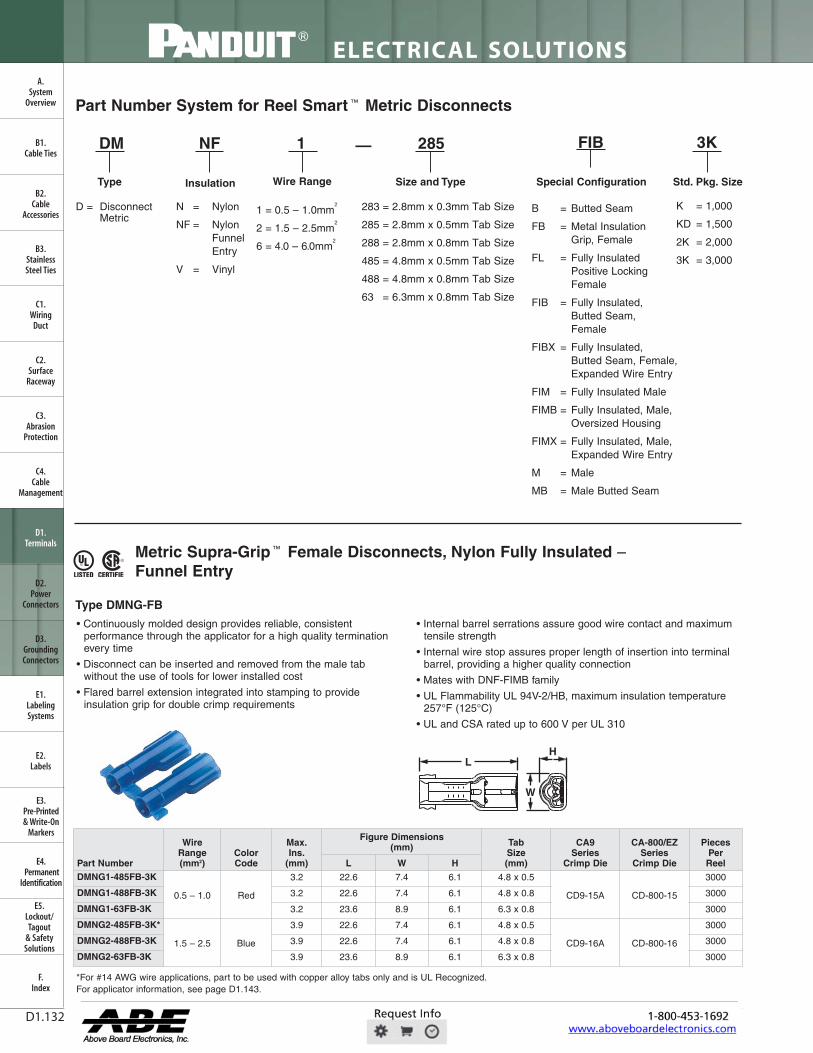
FilNDUIr
T T T
LISTED CERTIFIEI
ELECTRICAL SOLUTIONS
Order number of pieces required, in multiples of Standard Package Quantity. Prime items appear in BOLD.D1.132
B2.Cable
Accessories
C1.Wiring
Duct
C3.Abrasion
Protection
C4.Cable
Management
D1.Terminals
D2.Power
Connectors
E1.LabelingSystems
E2.Labels
E3.Pre-Printed & Write-On
Markers
F.Index
B3.StainlessSteel Ties
C2.Surface
Raceway
E5.Lockout/Tagout
& SafetySolutions
B1.Cable Ties
A.System
Overview
D3.GroundingConnectors
E4.Permanent
Identification
Metric Supra-Grip ™ Female Disconnects, Nylon Fully Insulated –Funnel Entry
• Continuously molded design provides reliable, consistentperformance through the applicator for a high quality terminationevery time
• Disconnect can be inserted and removed from the male tabwithout the use of tools for lower installed cost
• Flared barrel extension integrated into stamping to provideinsulation grip for double crimp requirements
• Internal barrel serrations assure good wire contact and maximumtensile strength
• Internal wire stop assures proper length of insertion into terminalbarrel, providing a higher quality connection
• Mates with DNF-FIMB family
• UL Flammability UL 94V-2/HB, maximum insulation temperature257°F (125°C)
• UL and CSA rated up to 600 V per UL 310
*For #14 AWG wire applications, part to be used with copper alloy tabs only and is UL Recognized.For applicator information, see page D1.143.
Part Number System for Reel Smart ™ Metric Disconnects
DM NF 1 285 FIB 3K
Type
N = Nylon
NF = Nylon FunnelEntry
V = Vinyl
B = Butted Seam
FB = Metal Insulation Grip, Female
FL = Fully InsulatedPositive LockingFemale
FIB = Fully Insulated, Butted Seam, Female
FIBX = Fully Insulated, Butted Seam, Female,Expanded Wire Entry
FIM = Fully Insulated Male
FIMB = Fully Insulated, Male, Oversized Housing
FIMX = Fully Insulated, Male, Expanded Wire Entry
M = Male
MB = Male Butted Seam
1 = 0.5 – 1.0mm2
2 = 1.5 – 2.5mm2
6 = 4.0 – 6.0mm2
K = 1,000
KD = 1,500
2K = 2,000
3K = 3,000
283 = 2.8mm x 0.3mm Tab Size
285 = 2.8mm x 0.5mm Tab Size
288 = 2.8mm x 0.8mm Tab Size
485 = 4.8mm x 0.5mm Tab Size
488 = 4.8mm x 0.8mm Tab Size
63 = 6.3mm x 0.8mm Tab Size
—
Insulation Size and Type Special Configuration Std. Pkg. Size
D = Disconnect Metric
L
W
H
Type DMNG-FB
Wire Range
Part Number
WireRange(mm2)
Color Code
Max.Ins.
(mm)
Figure Dimensions (mm) Tab
Size (mm)
CA9 Series
Crimp Die
CA-800/EZ Series
Crimp Die
Pieces Per ReelL W H
DMNG1-485FB-3K
0.5 – 1.0 Red
3.2 22.6 7.4 6.1 4.8 x 0.5
CD9-15A CD-800-15
3000
DMNG1-488FB-3K 3.2 22.6 7.4 6.1 4.8 x 0.8 3000
DMNG1-63FB-3K 3.2 23.6 8.9 6.1 6.3 x 0.8 3000
DMNG2-485FB-3K*
1.5 – 2.5 Blue
3.9 22.6 7.4 6.1 4.8 x 0.5
CD9-16A CD-800-16
3000
DMNG2-488FB-3K 3.9 22.6 7.4 6.1 4.8 x 0.8 3000
DMNG2-63FB-3K 3.9 23.6 8.9 6.1 6.3 x 0.8 3000
FWAHL
OpaqStan

io• ® LISTED CERTIFIED
I
-01
For technical assistance in the U.S., call 866-405-6654 (outside the U.S., see inside back cover for directory)
ELECTRICAL SOLUTIONS
D1.133
B2.Cable
Accessories
C1.Wiring
Duct
C3.Abrasion
Protection
C4.Cable
Management
D1.Terminals
D2.Power
Connectors
E1.LabelingSystems
E2.Labels
E3.Pre-Printed & Write-On
Markers
F.Index
B3.StainlessSteel Ties
C2.Surface
Raceway
E5.Lockout/Tagout
& SafetySolutions
B1.Cable Ties
A.System
Overview
D3.GroundingConnectors
E4.Permanent
Identification
Metric Disco-Lok ™ Female Disconnects, Nylon Fully Insulated –Funnel Entry
• Continuously molded design provides reliable, consistentperformance through the applicator for a high quality terminationevery time
• Disconnect can be inserted and removed from the male tab withoutthe use of tools for lower installed cost
• Unique locking mechanism design allows for low insertion forces(mating) and positive lock for high vibration applications where asecure connection is mandatory
• Fully insulated design provides protection from electrical shorts
• Flared barrel extension integrated into stamping to provideinsulation grip for double crimp requirements
• Insulation housing moves back and forth to engage and disengagelocking mechanism for repeated use
• Specialty tool required to install this disconnect (CT-1014)
• Mates with DNF-FIMB family
• UL Flammability UL 94V-2/HB, maximum insulation temperature257°F (125°C)
• Rated up to 300 V
Metric Female Disconnects, Nylon Fully Insulated – Funnel Entry
• Continuously molded design provides reliable, consistentperformance through the applicator for a high quality terminationevery time
• Disconnect can be inserted and removed from the male tab withoutthe use of tools for lower installed cost
• Fully insulated design provides protection from electrical shorts
• Internal wire stop assures proper length of insertion into terminalbarrel, providing a higher quality connection
• UL Flammability UL 94V-2/HB, maximum insulation temperature221°F (105°C)
• UL and CSA rated up to 600 V per UL 310
*UL/CSA standards do not exist for 2.8mm x 0.3mm (0.110" x 0.010") receptacles.For applicator information, see page D1.143.
W
HL
W
HL
Type DMNG-FL
Type DMNF-FIB
For applicator information, see page D1.143.
Part Number
Wire Range(mm2)
Color Code
Max.Ins.
(mm)
Figure Dimensions (mm) Tab
Size (mm)
CA9 Series
Crimp Die
CA-800/EZ Series
Crimp Die
Pieces Per ReelL W H
DMNG1-63FL-3K 0.5 – 1.0 Red 3.2 24.6 9.1 6.1 6.3 x 0.8 CD9-14A CD-800-14 3000
DMNG2-63FL-3K 1.5 – 2.5 Blue 3.8 24.6 9.1 6.4 6.3 x 0.8 CD9-14A CD-800-14 3000
Part Number
WireRange(mm2)
ColorCode
Max.Ins.
(mm)
Figure Dimensions (mm) Tab
Size(mm)
CA9 Series
Crimp Die
CA-800/EZ Series
Crimp Die
PiecesPerReelL W H
DMNF1-283FIB-3K* 0.5 – 1.0 Natural 3.0 18.0 4.8 3.8 2.8 x 0.3
CD9-7A CD-800-7
3000
DMNF1-285FIB-3K
0.5 – 1.0 Red
3.0 18.0 4.8 3.8 2.8 x 0.5 3000
DMNF1-288FIB-3K 3.0 18.0 4.8 3.8 2.8 x 0.8 3000
DMNF1-485FIB-3K 3.4 19.8 7.4 4.1 4.8 x 0.5
CD9-4A CD-800-4
3000
DMNF1-488FIB-3K 3.4 19.8 7.4 4.1 4.8 x 0.8 3000
DMNF1-63FIB-3K 3.4 21.3 8.9 5.6 6.3 x 0.8 3000
DMNF2-485FIB-3K
1.5 – 2.5 Blue
4.0 19.8 7.4 4.6 4.8 x 0.5
CD9-5A CD-800-5
3000
DMNF2-488FIB-3K 4.0 19.8 7.4 4.6 4.8 x 0.8 3000
DMNF2-63FIB-3K 4.1 21.3 8.9 5.6 6.3 x 0.8 3000
DMNF6-63FIB-2K 4.0 – 6.0 Yellow 5.6 24.4 8.9 5.8 6.3 x 0.8 CD9-13B CD-800-13 2000
FWAHL
OpaqStan

FilNDUIr
LISTED CERTIFIED
1
® 0 LISTED CERTIFIED
I-- --I --I H T
i
L
IMr
ELECTRICAL SOLUTIONS
Order number of pieces required, in multiples of Standard Package Quantity. Prime items appear in BOLD.D1.134
B2.Cable
Accessories
C1.Wiring
Duct
C3.Abrasion
Protection
C4.Cable
Management
D1.Terminals
D2.Power
Connectors
E1.LabelingSystems
E2.Labels
E3.Pre-Printed & Write-On
Markers
F.Index
B3.StainlessSteel Ties
C2.Surface
Raceway
E5.Lockout/Tagout
& SafetySolutions
B1.Cable Ties
A.System
Overview
D3.GroundingConnectors
E4.Permanent
Identification
Metric Disco ™ Female Disconnect, Nylon Fully Insulated –Expanded Wire Entry
• Continuously molded design provides reliable, consistentperformance through the applicator for a high quality terminationevery time
• Expanded wire entry designed to accommodate wire with a largerinsulation thickness
• Disconnect can be inserted and removed from the male tab withoutthe use of tools for lower installed cost
• Fully insulated design provides protection from electrical shorts
• Internal wire stop assures proper length of insertion into terminalbarrel, providing a higher quality connection
• UL Flammability UL 94V-2/HB, maximum insulation temperature221°F (105°C)
• UL and CSA rated up to 600 V per UL 310
W
L H
Metric Disco ™ Female Disconnects, Nylon Fully Insulated –Right Angle
• Continuously molded design provides reliable, consistentperformance through the applicator for a high quality terminationevery time
• Right angle design for use in limited space applications
• Fully insulated design provides protection from electrical shorts
• Internal wire stop assures proper length of insertion into terminalbarrel, providing a higher quality connection
• Disconnect can be inserted and removed from the male tab withoutthe use of tools for lower installed cost
• UL Flammability UL 94V-2/HB, maximum insulation temperature221°F (105°C)
• UL and CSA rated up to 600 V per UL 310
D H
LW
Type DMNF-FIBX
Type DMNFR-FIB
For applicator information, see page D1.143.
For applicator information, see page D1.143.
Part Number
Wire Range(mm2)
Color Code
Max.Ins.
(mm)
Figure Dimensions (mm) Tab
Size (mm)
CA9 SeriesCrimp Die
CA-800/EZSeries Crimp
Die
Pieces Per ReelL W H
DMNF1485FIBX-2K
0.5 – 1.0 Red
5.3 22.1 7.9 5.5 5.2/4.8 x 0.5
CD9-6B CD-800-6
2000DMNF1488FIBX-2K 5.3 22.1 7.9 5.5 5.2/4.8 x 0.8 2000DMNF1-63FIBX-2K 5.3 23.6 8.9 5.5 6.3 x 0.8 2000DMNF2485FIBX-2K
1.5 – 2.5 Blue
6.1 22.1 7.9 5.5 5.2/4.8 x 0.5
CD9-8B CD-800-8
2000DMNF2488FIBX-2K 6.1 22.1 7.9 5.5 5.2/4.8 x 0.8 2000DMNF2-63FIBX-2K 6.1 23.6 8.9 5.5 6.3 x 0.8 2000
Part Number
Wire Range(mm2)
Color Code
Max.Ins.
(mm)
Figure Dimension (mm) Tab
Size (mm)
CA9 Series
Crimp Die
CA-800/EZ Series
Crimp Die
Pieces Per ReelD L W H
DMNFR1485FIB-KD
0.5 – 1.0 Red
4.5 15.2 14.5 9.4 2.8 5.2/4.8 x 0.5
CD9-9C CD-800-9
1500
DMNFR1488FIB-KD 4.5 15.2 14.5 9.4 3.1 5.2/4.8 x 0.8 1500
DMNFR163FIB-KD 4.5 15.2 14.5 9.4 3.1 6.3 x 0.8 1500
DMNFR2485FIB-KD
1.5 – 2.5 Blue
4.5 15.2 14.5 9.4 2.8 5.2/4.8 x 0.5 1500
DMNFR2488FIB-KD 4.5 15.2 14.5 9.4 3.1 5.2/4.8 x 0.8 1500
DMNFR263FIB-KD 4.5 15.2 14.5 9.4 3.1 6.3 x 0.8 1500
FWAHL
OpaqStan

Cs LISTED CERTIFIED
® LISTED CERTIFIED
For technical assistance in the U.S., call 866-405-6654 (outside the U.S., see inside back cover for directory)
ELECTRICAL SOLUTIONS
D1.135
B2.Cable
Accessories
C1.Wiring
Duct
C3.Abrasion
Protection
C4.Cable
Management
D1.Terminals
D2.Power
Connectors
E1.LabelingSystems
E2.Labels
E3.Pre-Printed & Write-On
Markers
F.Index
B3.StainlessSteel Ties
C2.Surface
Raceway
E5.Lockout/Tagout
& SafetySolutions
B1.Cable Ties
A.System
Overview
D3.GroundingConnectors
E4.Permanent
Identification
Metric Disco ™ Female Disconnects, Vinyl Barrel Insulated –Funnel Entry
• Continuously molded design provides reliable, consistentperformance through the applicator for a high quality terminationevery time
• Disconnect can be inserted and removed from the male tab withoutthe use of tools for lower installed cost
• Internal barrel serrations assure good wire contact and maximumtensile strength
• Internal wire stop assures proper length of insertion into terminalbarrel, providing a higher quality connection
• UL Flammability UL 94V-0, maximum insulation temperature221°F (105°C)
• UL and CSA rated up to 600 V per UL 310
*Not UL Listed or CSA Certified.For applicator information, see page D1.143.
L
W
H
Metric DiscoGrip ™ Female Disconnects, Fully Insulated –Funnel Entry
• Continuously molded design provides reliable, consistentperformance through the applicator for a high quality terminationevery time
• Disconnect can be inserted and removed from the male tabwithout the use of tools for lower installed cost
• Premium nylon insulation retains its shape when crimped andprovides a tight grip around the wire insulation for maximumstrain relief
• Fully insulated design provides protection from electrical shorts
• Internal wire stop assures proper length of insertion into terminalbarrel, providing a higher quality connection
• Male tab couples with (all 6.3mm x 0.8mm) female disconnects
• UL Flammability UL 94V-2, maximum insulation temperature221°F (105°C)
• UL and CSA rated up to 600 V per UL 310
*Also approved for use with (2) 1.5 (#16) wires.For applicator information, see page D1.143.
W
LH
Type DMV-B
Type DMPF-FIB
Cross section of DiscoGrip™ Crimp showinginsulation crimp of the wire insulation.
Part Number
Wire Range(mm2)
Color Code
Max.Ins.
(mm)
Figure Dimension (mm) Tab
Size (mm)
CA9 Series
Crimp Die
CA-800/EZ Series
Crimp Die
Pieces Per ReelL W H
DMV1-485B-3K
0.5 – 1.0 Red
4.06 19.3 5.8 2.5 4.8 x 0.5 CD9-1A CD-800-1 3000
DMV1-488B-3K 4.06 18.8 5.8 2.5 4.8 x 0.8 CD9-2A CD-800-2 3000
DMV1-63B-3K 4.06 21.1 7.4 3.0 6.3 x 0.8 CD9-2A CD-800-2 3000
DMV2-485B-3K
1.5 – 2.5 Blue
4.52 19.6 5.3 2.5 4.8 x 0.5 CD9-2A CD-800-2 3000
DMV2-488B-3K 4.52 19.6 5.3 2.5 4.8 x 0.8 CD9-1A CD-800-1 3000
DMV2-63B-3K 4.52 21.1 7.4 3.0 6.3 x 0.8 CD9-2A CD-800-2 3000
DMV6-63-2K* 4.0 – 6.0 Yellow 5.84 24.1 7.4 3.0 6.3 x 0.8 CD9-3B CD-800-8 2000
Part Number
Wire Range(mm2)
Color Code
Max.Ins.
(mm)
Figure Dimensions (mm)
TabSize (mm)
CA9 Series
Crimp Die
CA-800/EZ Series
Crimp Die
Pieces Per ReelL W H
DMPF1-285FIB-3K
0.5 – 1.0 Red
3.4 18.0 4.8 4.3 2.8 x 0.5 CD9-12A CD-800-12 3000DMPF1-288FIB-3K 3.4 18.0 4.8 4.3 2.8 x 0.8 CD9-12A CD-800-12 3000DMPF1-485FIB-3K 3.4 19.8 7.9 4.3 4.8 x 0.5 CD9-10A CD-800-10 3000DMPF1-488FIB-3K 3.4 19.8 7.9 4.3 4.8 x 0.8 CD9-10A CD-800-10 3000DMPF1-63FIB-3K 3.4 21.3 8.9 5.6 6.3 x 0.8 CD9-13A CD-800-13 3000DMPF2-485FIB-3K
1.5 – 2.5 Blue
4.0 19.8 7.9 4.8 4.8 x 0.5 CD9-11A CD-800-11 3000DMPF2-488FIB-3K 4.0 19.8 7.9 4.8 4.8 x 0.8 CD9-11A CD-800-11 3000DMPF2-63FIB-3K 4.0 21.3 8.9 5.6 6.3 x 0.8 CD9-11A CD-800-11 3000DMPF6-63FIB-2K* 4.0 – 6.0 Yellow 5.5 24.4 8.9 5.8 6.3 x 0.8 CD9-13A CD-800-13 2000
FWAHL
OpaqStan

Al I I .7
® LISTED
r- / 1 ,-„,.. ...., ,,,
I
® SA® LISTED CERTIFIED
Mb ERRRAIMhl 1 ToPriTilmimp tj li
Prime items appear in BOLD.
ELECTRICAL SOLUTIONS
D1.136
B2.Cable
Accessories
C1.Wiring
Duct
C3.Abrasion
Protection
C4.Cable
Management
D1.Terminals
D2.Power
Connectors
E1.LabelingSystems
E2.Labels
E3.Pre-Printed & Write-On
Markers
F.Index
B3.StainlessSteel Ties
C2.Surface
Raceway
E5.Lockout/Tagout
& SafetySolutions
B1.Cable Ties
A.System
Overview
D3.GroundingConnectors
E4.Permanent
Identification
Metric DiscoGrip ™ Male Disconnects, Fully Insulated – Funnel Entry
• Continuously molded design provides reliable, consistentperformance through the applicator for a high quality terminationevery time
• Male tab can be inserted and removed from the female disconnectwithout the use of tools for lower installed cost
• Fully insulated design provides protection from electrical shorts
• Premium nylon insulation retains its shape when crimped andprovides a tight grip around the wire insulation for maximumstrain relief
• Oversized housing designed for maximum versatility to mate withmost commercially available fully insulated female disconnects
• Internal wire stop assures proper length of insertion into terminalbarrel, providing a higher quality connection
• Male tab couples with (all 6.3mm x 0.8mm) female disconnects
• UL Flammability UL 94V-2, maximum insulation temperature221°F (105°C)
• UL and CSA rated up to 600 V per UL 310
*To mate with other manufacturers’ fully insulated 6.3mm x 0.8mm female receptacles.For applicator information, see page D1.143.
W
LH
Metric Disco ™ Male Disconnects, Nylon Fully Insulated –Funnel Entry
• Continuously molded design provides reliable, consistentperformance through the applicator for a high quality terminationevery time
• Male tab couples with (all 6.3mm x 0.8mm) female disconnects
• Fully insulated design provides protection from electrical shorts
• Male tab can be inserted and removed from the female disconnectwithout the use of tools for lower installed cost
• Internal barrel serrations assure good wire contact and maximumtensile strength
• UL Flammability UL 94V-2/HB, maximum insulation temperature221°F (105°C)
• UL and CSA rated up to 600 V per UL 310
*To mate with other manufacturers’ fully insulated 6.3mm x 0.8mm female receptacles.For applicator information, see page D1.143.
L
W
H
Type DMPF-FIM
Type DMNF-FIM
Cross section of DiscoGrip ™ Crimp showinginsulation crimp of the wire insulation.
Part Number
Wire Range(mm2)
Color Code
Max.Ins.
(mm)
Figure Dimensions (mm) Tab
Size(mm)
CA9 Series
Crimp Die
CA-800/EZ Series
Crimp Die
Pieces Per ReelL W H
Standard HousingDMPF1-63FIM-2K 0.5 – 1.0 Red 3.4 22.9 10.4 7.4 6.3 x 0.8 CD9-10B CD-800-10 2000
DMPF2-63FIM-2K 1.5 – 2.5 Blue 4.0 22.9 10.4 7.4 6.3 x 0.8 CD9-11B CD-800-11 2000
Oversized HousingDMPF1-63FIMB-K* 0.5 – 1.0 Red 3.4 23.4 11.7 8.6 6.3 x 0.8 CD9-10B CD-800-10 1000
DMPF2-63FIMB-K* 1.5 – 2.5 Blue 4.1 23.4 11.7 8.6 6.3 x 0.8 CD9-11B CD-800-11 1000
Part Number
Wire Range(mm2)
Color Code
Max.Ins.
(mm)
Figure Dimensions (mm) Tab
Size (mm)
CA9 Series
Crimp Die
CA-800/EZ Series
Crimp Die
Pieces Per ReelL W H
Standard HousingDMNF1-63FIM-2K 0.5 – 1.0 Red 3.4 22.9 10.7 7.5 6.3 x 0.8 CD9-4B CD-800-4 2000
DMNF2-63FIM-2K 1.5 – 2.5 Blue 4.0 22.9 10.7 7.5 6.3 x 0.8 CD9-5B CD-800-5 2000
Oversized HousingDMNF1-63FIMB-K* 0.5 – 1.0 Red 3.4 23.1 11.4 8.6 6.3 x 0.8 CD9-4B CD-800-4 1000
DMNF2-63FIMB-K* 1.5 – 2.5 Blue 4.1 23.1 11.7 8.4 6.3 x 0.8 CD9-5B CD-800-5 1000
FWAHL
OpaqStan

USTE0 CERTIFIED
I
SA® CERITIED
For technical assistance in the U.S., call 866-405-6654 (outside the U.S., see inside back cover for directory)
ELECTRICAL SOLUTIONS
D1.137
B2.Cable
Accessories
C1.Wiring
Duct
C3.Abrasion
Protection
C4.Cable
Management
D1.Terminals
D2.Power
Connectors
E1.LabelingSystems
E2.Labels
E3.Pre-Printed & Write-On
Markers
F.Index
B3.StainlessSteel Ties
C2.Surface
Raceway
E5.Lockout/Tagout
& SafetySolutions
B1.Cable Ties
A.System
Overview
D3.GroundingConnectors
E4.Permanent
Identification
Metric Disco ™ Male Disconnects, Nylon Fully Insulated –Expanded Wire Entry
• Continuously molded design provides reliable, consistentperformance through the applicator for a high quality terminationevery time
• Expanded wire entry designed to accommodate wire with a largerinsulation thickness
• Male tab couples with (all 6.3mm x 0.8mm) female disconnects
• Fully insulated design provides protection from electrical shorts
• Male tab can be inserted and removed from the female disconnectwithout the use of tools for lower installed cost
• Internal barrel serrations assure good wire contact and maximumtensile strength
• UL Flammability UL 94V-2/HB, maximum insulation temperature221°F (105°C)
• UL and CSA rated up to 600 V per UL 310
*CSA Certified for use with (2) #16 AWG or (2) #18 AWG wires.**CSA Certified for use with (2) #18 AWG, (2) #20 AWG, or (2) #22 AWG wires.For applicator information, see page D1.143.
L
W
H
Metric Disco ™ Male Disconnects, Nylon Barrel Insulated –Funnel Entry
• Continuously molded design provides reliable, consistentperformance through the applicator for a high quality terminationevery time
• Male tab couples with (all 6.3mm x 0.8mm) female disconnects
• Male tab can be inserted and removed from the female disconnectwithout the use of tools for lower installed cost
• Metal insulation grip sleeve crimps to wire insulation, providingprotection to the crimp joint during high vibration applications
• Internal barrel serrations assure good wire contact and maximumtensile strength
• UL Flammability UL 94V-2/HB, maximum insulation temperature221°F (105°C)
• Rated up to 600 V
*Not CSA Certified.For applicator information, see page D1.143.
L
Type DMNF-FIMX
Type DMNF-M
Part Number
Wire Range(mm2)
Color Code
Max.Ins.
(mm)
Figure Dimensions (mm) Tab
Size (mm)
CA9Series
Crimp Die
CA-800/EZSeries
Crimp Die
Pieces Per ReelL W H
DMNF1-63FIMX-2K* 0.5 – 1.0 Red 6.2 24.6 10.4 7.4 6.3 x 0.8 CD9-8B CD-800-8 2000
DMNF2-63FIMX-2K** 1.5 – 2.5 Blue 6.2 24.6 10.4 7.4 6.3 x 0.8 CD9-8B CD-800-8 2000
Part Number
Wire Range(mm2)
Color Code
Max.Ins.
(mm)
Figure Dimensions (mm) Tab
Size (mm)
CA9 Series
Crimp Die
CA-800/EZ Series
Crimp Die
Pieces Per ReelL
DMNF1-63M-3K 0.5 – 1.0 Red 3.7 22.9 6.3 x 0.8 CD9-1A CD-800-1 3000
DMNF2-63M-3K 1.5 – 2.5 Blue 4.1 22.9 6.3 x 0.8 CD9-2A CD-800-2 3000
DMNF6-63M-2K* 4.0 – 6.0 Yellow 5.7 24.1 6.3 x 0.8 CD9-3B CD-800-3 2000
FWAHL
OpaqStan

Pi%INUIT' Ai=
1
SA® CERIFIED
ELECTRICAL SOLUTIONS
Order number of pieces required, in multiples of Standard Package Quantity. Prime items appear in BOLD.D1.138
Metric Disco ™ Male Disconnects, Vinyl Barrel Insulated – Funnel Entry
• Continuously molded design provides reliable, consistentperformance through the applicator for a high quality terminationevery time
• Male tab couples with (all 6.3mm x 0.8mm) female disconnects
• Insulation support helps to prevent wire damage inbending applications
• Male tab can be inserted and removed from the female disconnectwithout the use of tools for lower installed cost
• UL Flammability UL 94V-0, maximum insulation temperature194°F (90°C)
• Rated up to 600 V
L
Metric Pin Terminals, Vinyl Insulated – Funnel Entry
• Continuously molded design provides reliable, consistentperformance through the applicator for a high quality terminationevery time
• Solid pin designed to prevent damage to the wire from overtightening, resulting in a reliable electrical connection
• Insulation support helps to prevent wire damage inbending applications
• For use with pin-type terminal blocks
• UL Flammability UL 94V-0, maximum insulation temperature221°F (105°C)
• Rated up to 600 V
L
P
W
Type DMV-MB
Type PMV-P
*DMV6-63M-2K is not CSA Certified.For applicator information, see page D1.143.
For applicator information, see page D1.143.
B2.Cable
Accessories
C1.Wiring
Duct
C3.Abrasion
Protection
C4.Cable
Management
D1.Terminals
D2.Power
Connectors
E1.LabelingSystems
E2.Labels
E3.Pre-Printed & Write-On
Markers
F.Index
B3.StainlessSteel Ties
C2.Surface
Raceway
E5.Lockout/Tagout
& SafetySolutions
B1.Cable Ties
A.System
Overview
D3.GroundingConnectors
E4.Permanent
Identification
Part Number
Wire Range(mm2)
Color Code
Max.Ins.
(mm)
Figure Dimension(mm) Tab
Size (mm)
CA9 Series
Crimp Die
CA-800/EZ Series
Crimp Die
Pieces Per ReelL
DMV1-63MB-3K 0.5 – 1.0 Red 3.9 22.9 6.3 x 0.8 CD9-1A CD-800-1 3000
DMV2-63MB-3K 1.5 – 2.5 Blue 4.5 22.9 6.3 x 0.8 CD9-2A CD-800-2 3000
DMV6-63M-2K* 4.0 – 6.0 Yellow 6.1 24.4 6.3 x 0.8 CD9-3B CD-800-3 2000
Part Number
WireRange(mm2)
ColorCode
Max.Ins.
(mm)
Figure Dimensions (mm) CA9
SeriesCrimp Die
CA-800/EZ Series
Crimp Die
PiecesPer ReelL W P
PMV1-P12B-3K 0.5 – 1.0 Red 3.8 22.6 2.0 10.0 CD9-1A CD-800-1 3000
PMV2-P12B-3K 1.5 – 2.5 Blue 4.3 22.6 2.0 10.0 CD9-2A CD-800-2 3000
FWAHL
OpaqStan

LISTED CERTIFIED
For technical assistance in the U.S., call 866-405-6654 (outside the U.S., see inside back cover for directory)
ELECTRICAL SOLUTIONS
D1.139
B2.Cable
Accessories
C1.Wiring
Duct
C3.Abrasion
Protection
C4.Cable
Management
D1.Terminals
D2.Power
Connectors
E1.LabelingSystems
E2.Labels
E3.Pre-Printed & Write-On
Markers
F.Index
B3.StainlessSteel Ties
C2.Surface
Raceway
E5.Lockout/Tagout
& SafetySolutions
B1.Cable Ties
A.System
Overview
D3.GroundingConnectors
E4.Permanent
Identification
Metric Male Blade Adapters, Vinyl Insulated – Funnel Entry
• Continuously molded design provides reliable, consistentperformance through the applicator for a high quality terminationevery time
• Flat blade design to prevent damage to the wire from overtightening, resulting in a reliable electrical connection
• For use with blade-type terminal blocks
• Insulation support helps to prevent wire damage inbending applications
• UL Flammability UL 94V-0, maximum insulation temperature194°F (90°C)
• Rated up to 600 V
Metric Butt Splices, Nylon Insulated
• One-side machine applied termination replaces manual crimping
• Funnel entry on machine termination side to increase productivity
• Also hand crimped with Panduit CT-100A, CT-1550, or CT-1551crimping tools
• Barrel locating ribs provide for accurate hand tool placement
• Available with insulation crimp premium grade nylon
• Brazed seam with center wire stop for increased performanceand productivity
• UL Flammability UL 94V-2/HB, maximum insulation temperature221°F (105°C)
• UL and CSA rated up to 600 V per UL 486C
L
Y
L
Type DMV-MB
Type BSMN, BSMP
For applicator information, see page D1.143.
For applicator information, see page D1.143.
Part Number
WireRange(mm2)
ColorCode
Max.Ins.
(mm)
Figure Dimensions (mm) Tab
Size(mm)
CA9 Series
Crimp Die
CA-800/EZ Series
Crimp Die
PiecesPer ReelL Y
DMV1-37MB-3K 0.5 – 1.0 Red 3.9 22.9 10.5 3.7 x 0.8 CD9-1A CD-800-1 3000
DMV2-37MB-3K 1.5 – 2.5 Blue 4.5 22.9 10.5 3.7 x 0.8 CD9-2A CD-800-2 3000
Part Number
WireRange(mm2)
ColorCode
Max.Ins.
(mm)
Figure Dimension (mm) CA9
SeriesCrimp Die
CA-800/EZ Series
Crimp Die
PiecesPer ReelL
BSMN1-3K 0.5 – 1.5 Red 3.8 24.1 CD9-1A CD-800-1 3000BSMN2-3K 1.5 – 2.5 Blue 4.3 24.1 CD9-2A CD-800-2 3000BSMN6-2K 4.0 – 6.0 Yellow 5.8 24.1 CD9-3B CD-800-3 2000BSMP1-3K 0.5 – 1.5 Red 3.8 24.1 CD9-1A CD-800-1 3000BSMP2-3K 1.5 – 2.5 Blue 4.3 24.1 CD9-2A CD-800-2 3000
FWAHL
OpaqStan

T T T 7 T T T
ELECTRICAL SOLUTIONS
Order number of pieces required, in multiples of Standard Package Quantity. Prime items appear in BOLD.D1.140
B2.Cable
Accessories
C1.Wiring
Duct
C3.Abrasion
Protection
C4.Cable
Management
D1.Terminals
D2.Power
Connectors
E1.LabelingSystems
E2.Labels
E3.Pre-Printed & Write-On
Markers
F.Index
B3.StainlessSteel Ties
C2.Surface
Raceway
E5.Lockout/Tagout
& SafetySolutions
B1.Cable Ties
A.System
Overview
D3.GroundingConnectors
E4.Permanent
Identification
Features and Benefits – Reel Smart ™ Ferrules
Insulated Ferrules – Single WireType FS and FSD
Maximum insulation temperature 192°F (89°C)
Color-coded polypropyleneidentifies wire size
Seamless tubularbarrel providesconsistent qualitycrimps
Panduit ferrules are available in strips and reels for wiring applications from #20 – 14 AWG. Offerings include insulatedferrules in singe wire configurations. These insulated ferrules are color-coded to DIN standards.
Part Number System for Reel Smart ® Ferrules
D = DIN
= Standard(leave blank)
S = Single
S —D 75 8
Wire Type Color Code Wire Size (mm2) DIN Length
F
Type
F = Ferrule 0 = Black
2 = Red
3 = Orange
4 = Yellow
6 = Blue
7 = Light Blue
8 = Gray
10 = White
10
Color-Code Number
5K or DSL
3K = 3,000
5K = 5,000
DSL = 50
Std. Pkg. Size
FWAHL
OpaqStan
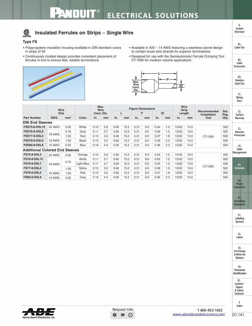
P IF SA®
I
I
-4-
For technical assistance in the U.S., call 866-405-6654 (outside the U.S., see inside back cover for directory)
ELECTRICAL SOLUTIONS
D1.141
B2.Cable
Accessories
C1.Wiring
Duct
C3.Abrasion
Protection
C4.Cable
Management
D1.Terminals
D2.Power
Connectors
E1.LabelingSystems
E2.Labels
E3.Pre-Printed & Write-On
Markers
F.Index
B3.StainlessSteel Ties
C2.Surface
Raceway
E5.Lockout/Tagout
& SafetySolutions
B1.Cable Ties
A.System
Overview
D3.GroundingConnectors
E4.Permanent
Identification
Insulated Ferrules on Strips – Single Wire
• Polypropylene insulation housing available in DIN standard colorsin strips of 50
• Continuously molded design provides consistent placement offerrules in tool to ensure fast, reliable terminations
• Available in #20 – 14 AWG featuring a seamless barrel design to contain loose wire strands for superior terminations
• Designed for use with the Semiautomatic Ferrule Crimping Tool CT-1000 for medium volume applications
Type FS
ID
L
PMax.WireInsul.Dia.
Part Number
WireSize
Color
Max.Wire
Insul. Dia.
Figure DimensionsWireStrip
LengthRecommended
InstallationTool
Std.Pkg.Qty.
L P ID
AWG mm2 In. mm In. mm In. mm In. mm In. mm
DIN End SleevesFSD75-8-DSL10 20 AWG 0.50 White 0.10 2.6 0.60 15.2 0.31 8.0 0.04 1.0 13/32 10.0
CT-1000
500
FSD76-8-DSL818 AWG
0.75 Gray 0.11 2.7 0.60 15.2 0.31 8.0 0.06 1.5 13/32 10.0 500
FSD77-8-DSL2 1.00 Red 0.12 3.0 0.60 15.2 0.31 8.0 0.07 1.8 13/32 10.0 500
FSD78-8-DSL0 16 AWG 1.50 Black 0.13 3.2 0.60 15.2 0.31 8.0 0.09 2.3 13/32 10.0 500
FSD80-8-DSL6 14 AWG 2.50 Blue 0.16 4.0 0.60 15.2 0.31 8.0 0.09 2.3 13/32 10.0 500
Additional Colored End SleevesFS75-8-DSL3 20 AWG 0.50 Orange 0.10 2.6 0.60 15.2 0.31 8.0 0.04 1.0 13/32 10.0
CT-1000
500
FS76-8-DSL10
18 AWG0.75
White 0.11 2.7 0.60 15.2 0.31 8.0 0.05 1.2 13/32 10.0 500
FS76-8-DSL7 Light Blue 0.11 2.7 0.60 15.2 0.31 8.0 0.05 1.2 13/32 10.0 500
FS77-8-DSL4 1.00 Yellow 0.12 3.0 0.60 15.2 0.31 8.0 0.06 1.5 13/32 10.0 500
FS78-8-DSL2 16 AWG 1.50 Red 0.13 3.2 0.60 15.2 0.31 8.0 0.07 1.8 13/32 10.0 500
FS80-8-DSL8 14 AWG 2.50 Gray 0.16 4.0 0.60 15.2 0.31 8.0 0.09 2.3 13/32 10.0 500
FWAHL
OpaqStan

111
PERMED
M
ELECTRICAL SOLUTIONS
Order number of pieces required, in multiples of Standard Package Quantity. Prime items appear in BOLD.D1.142
B2.Cable
Accessories
C1.Wiring
Duct
C3.Abrasion
Protection
C4.Cable
Management
D1.Terminals
D2.Power
Connectors
E1.LabelingSystems
E2.Labels
E3.Pre-Printed & Write-On
Markers
F.Index
B3.StainlessSteel Ties
C2.Surface
Raceway
E5.Lockout/Tagout
& SafetySolutions
B1.Cable Ties
A.System
Overview
D3.GroundingConnectors
E4.Permanent
Identification
Type FS
Semiautomatic Ferrule Crimping Tool – CT-1000
• Innovative rapid load design utilizes continuously molded ferrulesto significantly reduce installation time
• Controlled cycle tool cuts, strips, and crimps wire to maximize efficiency
• Adjustable die setting allows termination of all Panduit #20 – 14 AWG continuously molded ferrules with a single tool
Part Number Part Description
Std.Pkg.Qty.
CT-1000 Controlled cycle crimp tool with trapezoid profile for #20 – 14 AWG (0.50 – 2.5mm²)insulated continuously molded ferrules on strips. Also cuts and strips wire.
1
Insulated Ferrules on Reels – Single Wire
• Polypropylene insulation housing available in DIN standard colorsin reels of 3000 and 5000
• Designed specifically for use with the Ferrule Applicator (CA10) forhigh volume applications
• Continuously molded design provides consistent placement offerrules in applicator to ensure fast, reliable terminations
• Available in #20 – 14 AWG featuring a seamless barrel design tocontain loose wire strands for superior terminations
ID
L
PMax.WireInsul.Dia.
Part Number
WireSize
Color
Max.Wire
Insul. Dia.
Figure DimensionsWireStrip
LengthCA10SeriesDies
PiecesPer Reel
L P ID
AWG mm2 In. mm In. mm In. mm In. mm In. mm
DIN End SleevesFSD75-8-5K10 20 AWG 0.50 White 0.10 2.6 0.57 14.5 0.31 8.0 0.04 1.0 13/32 10.0
CD10-15000
FSD76-8-5K8 18 AWG 0.75 Gray 0.11 2.7 0.57 14.5 0.31 8.0 0.05 1.2 13/32 10.0 5000
FSD77-8-5K2 18 AWG 1.00 Red 0.12 3.0 0.57 14.5 0.31 8.0 0.06 1.5 13/32 10.0CD10-2
5000
FSD78-8-5K0 16 AWG 1.50 Black 0.13 3.2 0.57 14.5 0.31 8.0 0.07 1.8 13/32 10.0 5000
FSD80-8-3K6 14 AWG 2.50 Blue 0.16 4.0 0.57 14.5 0.31 8.0 0.09 2.3 13/32 10.0 CD10-3 3000
Additional Colored End SleevesFS75-8-5K3 20 AWG 0.50 Orange 0.10 2.6 0.57 14.5 0.31 8.0 0.04 1.0 13/32 10.0
CD10-1
5000
FS76-8-5K10 18 AWG 0.75 White 0.11 2.7 0.57 14.5 0.31 8.0 0.05 1.2 13/32 10.0 5000
FS76-8-5K7 18 AWG 0.75 Light Blue 0.11 2.7 0.57 14.5 0.31 8.0 0.05 1.2 13/32 10.0 5000
FS77-8-5K4 18 AWG 1.00 Yellow 0.12 3.0 0.57 14.5 0.31 8.0 0.06 1.5 13/32 10.0CD10-2
5000
FS78-8-5K2 16 AWG 1.50 Red 0.13 3.2 0.57 14.5 0.31 8.0 0.07 1.8 13/32 10.0 5000
FS80-8-3K8 14 AWG 2.50 Gray 0.16 4.0 0.57 14.5 0.31 8.0 0.09 2.3 13/32 10.0 CD10-3 3000
FWAHL
OpaqStan

For technical assistance in the U.S., call 866-405-6654 (outside the U.S., see inside back cover for directory)
ELECTRICAL SOLUTIONS
D1.143
B2.Cable
Accessories
C1.Wiring
Duct
C3.Abrasion
Protection
C4.Cable
Management
D1.Terminals
D2.Power
Connectors
E1.LabelingSystems
E2.Labels
E3.Pre-Printed & Write-On
Markers
F.Index
B3.StainlessSteel Ties
C2.Surface
Raceway
E5.Lockout/Tagout
& SafetySolutions
B1.Cable Ties
A.System
Overview
D3.GroundingConnectors
E4.Permanent
Identification
Reel Smart ™ Ferrule Applicator – CA10
• Designed for use with continuously molded ferrules in reels of3,000 or 5,000 for high volume applications
• Precision ferrule indexing through applicator for optimum reliabilityand productivity
• Universal base plate allows compatibility with the Panduit CP-871 electric press, and other commercially available benchpresses and automatic wire processing (AWP) machines
• Quick change die sets terminate the entire ferrule line to providefast product change over and reduction in setup time; dies sold separately
CA9 Ezair ™ and CA-800EZ Applicators• Designed to terminated all continuously molded terminals,
disconnects, and splices in reels of 3,000 or 5,000 for high volume applications
• Precision terminal indexing through applicator for optimumreliability and productivity
• Universal base plate allows compatibility with the Panduit CP-871 electric press, and other commercially available benchpresses and automatic wire processing (AWP) machines
• Quick change die sets allow for fast product change over andreduction in setup time; dies sold separately
*AMP is a registered trademark of Tyco Electronics.For crimp die information, refer to pages D1.145 and D1.146.
Part Number Part Description
Std.Pkg.Qty.
CA-800EZ* Applicator: runs in the AMP* Model T and K bench presses. True “quick change”applicator — no additional plates are necessary. Slide right into the press for easychangeover. Uses CD-800 series die inserts.
1
CA9 CA9 Ezair ™ Applicator: terminates the entire Reel Smart ™ product line. This greatlyreduces set up and maintenance time and increases productivity. This patentedapplicator is so smart it automatically adjusts feed stroke to the correct pitch andlength for the entire product line. Crimp die changeover in less than 1 minute,minimizes downtime and increases productivity. Fast, easy loading of terminal partswithout special instructions or setup personnel. Simply feed the parts strip into theapplicator. All the necessary adjustments are made by the dies and the automatic feed stroke.Used in CP-871 electric press.Safety lockout guard ensures operator safety.Positive stop adjustment rings allow for electrical and insulation crimp adjustments as desired.
1
Part Number Part Description
Std.Pkg.Qty.
CA10 Applicator used to terminates entire line of Reel Smart ™ Continuously Molded Ferruleson reels. For use with CP-871 Electric Press and CD10 series die sets.
1
CD10-1 Die insert to be used with the CA10 applicator to terminate FS75, FSD75, FS76 andFSD76 Reel Smart™ Continuously Molded Ferrules.
1
CD10-2 Die insert to be used with the CA10 applicator to terminate FS77, FSD77, FS78 andFSD78 Reel Smart ™ Continuously Molded Ferrules.
1
CD10-3 Die insert to be used with the CA10 applicator to terminate FS80 and FSD80 Reel Smart™ Continuously Molded Ferrules.
1
FWAHL
OpaqStan

ELECTRICAL SOLUTIONS
Order number of pieces required, in multiples of Standard Package Quantity. Prime items appear in BOLD.D1.144
B2.Cable
Accessories
C1.Wiring
Duct
C3.Abrasion
Protection
C4.Cable
Management
D1.Terminals
D2.Power
Connectors
E1.LabelingSystems
E2.Labels
E3.Pre-Printed & Write-On
Markers
F.Index
B3.StainlessSteel Ties
C2.Surface
Raceway
E5.Lockout/Tagout
& SafetySolutions
B1.Cable Ties
A.System
Overview
D3.GroundingConnectors
E4.Permanent
Identification
Electric Bench Press
• For use with Panduit Applicators and Reel Smart ™ ContinuouslyMolded Terminals and Ferrules to provide a superior solution forquality, high volume terminations
• CP-871 press has a microprocessor based controller and LCDthat displays text messages and cycle count withmulti-language capability
• Tool crimp height adjustment feature allows user to easily set andmaintain desired crimp height for consistent performance
• Applicator can be changed without the use of tools to facilitatefaster changeover for lower cost of ownership
PartNumber Part Description
Std.Pkg.Qty.
CP-871 Electric press:4000+ terminations per hour.Operates on 110 VAC current/60 Hz, 220 VAC current/50 Hz (field convertible).Overall size (without reel): 13" x 33" x 16".Total weight (without reel): 176 lbs.Includes foot pedal.
1
Part Number Part Description
Std.Pkg.Qty.
DSF-RS For use with black oxide cutter dies. 1
DSF-NP For use with nickel-plated cutter dies. 1
Die Sharpening Kits
• Used to resharpen cutting edges and maintain reliability of CD-800 and CD9 series cutter dies
FWAHL
OpaqStan

For technical assistance in the U.S., call 866-405-6654 (outside the U.S., see inside back cover for directory)
ELECTRICAL SOLUTIONS
D1.145
B2.Cable
Accessories
C1.Wiring
Duct
C3.Abrasion
Protection
C4.Cable
Management
D1.Terminals
D2.Power
Connectors
E1.LabelingSystems
E2.Labels
E3.Pre-Printed & Write-On
Markers
F.Index
B3.StainlessSteel Ties
C2.Surface
Raceway
E5.Lockout/Tagout
& SafetySolutions
B1.Cable Ties
A.System
Overview
D3.GroundingConnectors
E4.Permanent
Identification
Die Information
TA13721A01 = 60/40 Solder Slug with 1/8" (.125) outer diameter.TA13722A01 = 60/40 Solder Slug with 3/16" (.188) outer diameter.(1) Insulation Support: Minimum wire insulation strain relief for normal applications.Plastic and DiscoGrip™ Insulation Crimp: Secondary wire insulation strain relief for high vibration or conductor strain applications.Metal Insulation Grip: Maximum wire insulation strain relief for high vibration or conductor strain applications.***Modified lower die for barrel insulated disconnects DV-B series. Available as a complete die set or just lower die assembly.
Table continues on page D1.146
Part NumberAWG Wire
RangeColorCode
(1) Wire InsulationStrain Relief Part No. Prefix
60/40 Solder SlugDia. Spare Part Number
In. mm Crimp Die Cutter Die Lower DieCD-800-1 22 – 18,
22 – 16
Red
Plastic Ins. Crimp,Insulation Support,Metal Ins. Crimp,Plastic Ins. Crimp
PV, DV-MB, DV-B, BSN,PN, PNF, DNF-M, BSP
(Premium Nylon)
0.188 4.78
TD13471C06 CD-800-1
TD13483C02CD-800 C1
TD17755B01 CD-1
CD-800-1D*** 22–18 CD-800-2 16 – 14,
18 – 14
Blue
Plastic Ins. Crimp,Insulation Support,Metal Ins. Crimp,Plastic Ins. Crimp
PV, DV-MB, DV-B, BSN,PN, PNF, DNF-M, BSP
(Premium Nylon)
TD13473C05CD-800-2
TD13486C03CD-800C-2
TD17756B01C-2
CD-800-2D*** 16 – 14CD-800-3 12 – 10,
14 – 10, 16 – 12
Yellow Plastic Ins. Crimp,Plastic Ins. Crimp,Metal Ins. Crimp,Plastic Ins. Crimp,Metal Ins. Crimp
PV, PV12, DV, DV-C,PN12, PV12, DV-M,
PN, PNF, DNF-M
TD13475C06CD-800-3
TD13489C02CD-800C-3
TD17757B01C-3
CD-800-4 12 – 18 Red Insulation Support DNF-FIB, DNF-FIM,DNF-FIMB, DNF-LPB
TD13833C06CD-800-4, 10
TD13505C02CD-800
C-4
TD17758B01C-4, 10
CD-800-5 16 – 14 Blue Insulation Support DNF-FIB, DNF-FIM,DNF-FIMB, DNF-LPB
TD13634C05CD-800-5, 11
TD13508C02CD-800
C-5
TD17759B01C-5, 11
CD-800-6 22 – 18 Red Insulation Support DNF-FIBX TD13652C04CD-800-6
TD13499C02CD-800C-6
TD17760B01C-6
CD-800-7 22 – 18 Red Insulation Support DNF-110FIB, DNF-111FIB, DNF-112FIB
0.125 3.18 TD13477C05CD-800-7, 12
TD13492C03CD-800
C-7
TD17761B01C-7, 12
CD-800-8 22 – 18, 16 – 14
Red/Blue
Insulation Support DNF-FIBX, DNF-FIMX,DNF-FIMX
0.188 4.78 TD13481C06CD-800-8
TD13502C03CD-800
C-8
TD17762B01C-8
CD-800-9 22 – 14 Red/Blue
Insulation Support DNFR-FIB 0.125 3.18 TD13479C05CD-800-9
TD13495C02CD-800
C-9
TD17763B01C-9
CD-800-10 22 – 18 Red DiscoGrip™
Insulation CrimpDPF-FIB, DPF-FIM,
DPF-FIMB, DPF-LPB
0.188 4.78
TD13633C06CD-800-4, 10
TD16233C02CD-800
C-10
TD17758B01C-4, 10
CD-800-11 16 – 14 Blue DiscoGrip™
Insulation CrimpDPF-FIM, DPF-FIMB,DPF-FIB, DPF-LPB
TD13634C05CD-800-5, 10
TD16243C01CD-800
C-11
TD17759B01CD-5, 11
CD-800-12 22 – 18 Red DiscoGrip™
Insulation CrimpDPF-110FIB, DPF-111FIB
0.125 3.18 TD13477C05CD-800-7, 12
TD16235C02CD-800
C-12
TD17761B01C-7, 12
CD-800-13 12 – 10 Yellow Insulation Support,DiscoGrip™
Insulation Crimp
DNF-FIB, DPF-FIB 0.188 4.78 TD19116C03CD-800-13
TD19115C05CD-800
C-13
TD19424B01C-13
CD-800-14 22 – 18, 16 – 14
Red/Blue
Metal InsulationCrimp
DNG-FL 0.125 3.18 TD22943C01CD-800-14
TD22944C01CD-800
C-14
TD22960B01C-14
CD-800-15 22 – 18 Red Metal InsulationCrimp
DNG-FB
0.188 4.78
TD22945C01CD-800-15
TD22946C01CD-800
C-15
TD22961B01C-15
CD-800-16 16 – 14 Blue Metal InsulationCrimp
DNG-FB TD22947C01CD-800-16
TD22948C01CD-800
C-16
TD22962B01C-16
CD-800-17 12 – 10 Yellow Insulation Support BSN TD23601C01CD-800-17
TD23600C01CD-800-17
TD23612B01CD-800-17
CD-800-18 12 – 10 Yellow Plastic InsulationCrimp
DNF-FIMB TD13475C06CD-800-18
TD23773C01CD-800-18
TD17757B01CD-800-18
FWAHL
OpaqStan

ELECTRICAL SOLUTIONS
Order number of pieces required, in multiples of Standard Package Quantity. Prime items appear in BOLD.D1.146
B2.Cable
Accessories
C1.Wiring
Duct
C3.Abrasion
Protection
C4.Cable
Management
D1.Terminals
D2.Power
Connectors
E1.LabelingSystems
E2.Labels
E3.Pre-Printed & Write-On
Markers
F.Index
B3.StainlessSteel Ties
C2.Surface
Raceway
E5.Lockout/Tagout
& SafetySolutions
B1.Cable Ties
A.System
Overview
D3.GroundingConnectors
E4.Permanent
Identification
Part NumberColorCode
AWG WireRange
Wire Insulation Strain Relief Part No. Prefix
60/40 SolderSlug Diameter Spare Part Number
In. mm Crimp Die Cutter Die Lower DieCD9-1A
Red
22 – 16,22 – 18
Insulation Support,Plastic Ins. Crimp,Plastic Ins. Crimp,
Metal Ins. Grip
BSN, BSP, PV,DV-B, DV-MB, PN, PNF,
DNF-M0.188 4.78
TD24129C01 TD24139C01 TD24149C01CD9-1AD***22 – 18
Plastic InsulationCrimp,
Metal Insulation Grip
PV, DV-B, DV-MB, PN, PNF,DNF-M 0.188 4.78
CD9-1B22 – 18 Plastic Insulation
Crimp PV-56R, PV-38R 0.188 4.78
CD9-2A
Blue
18 – 14,16 – 14
Insulation Support,Plastic Ins. Crimp,Insulation Support,Plastic Ins. Crimp,
Metal Ins. Grip
BSN, BSP, BSN, PV, DV-B, DV-MB, PN, PNF,
DNF-M0.188 4.78
TD24130C01 TD24140C01 TD23712C01CD9-2AD***
16 – 14
Insulation Support,Plastic Insulation
Crimp,Metal Insulation Grip
BSN, PV, DV-B, DV-MB, PN,PNF, DNF-M 0.188 4.78
CD9-2B16 – 14 Plastic Insulation
Crimp PV-56R, PV-38R 0.188 4.78
CD9-3BYellow 12 – 10,
16 – 12
Plastic Ins. Crimp,Metal Ins. Grip,
Plastic Ins. Crimp
PV, DV, DV-M, PN, PNF,DNF-M, PV12, PN12 0.188 4.78 TD24131C01 TD24141C01 TD23713C01
CD9-4ARed
22 – 18 Insulation Support DNF-FIB, DNF-LPB 0.188 4.78TD24132C01 TD24142C01 TD24150C01CD9-4B 22 – 18 Insulation Support DNF-FIM, DNF-FIMB 0.188 4.78
CD9-5ABlue
16 – 14 Insulation Support DNF-FIB, DNF-LPB 0.188 4.78TD24133C01 TD24143C01 TD24151C01CD9-5B 16 – 14 Insulation Support DNF-FIM, DNF-FIMB 0.188 4.78
CD9-6B Red 22 – 18 Insulation Support DNF-FIBX 0.188 4.78 TD23700C01 TD23683C01 TD23716C01CD9-7A Red 22 – 18 Insulation Support DNF-110, 111, 112FIB 0.125 3.18 TD23701C02 TD23684C01 TD23717C01CD9-8B
Blue/Red
16 – 14,22 – 14 Insulation Support DNF-FIBX,
DNF-FIMX 0.188 4.78 TD23702C01 TD23685C01 TD23718C01
CD9-9C Red/Blue 22 – 14 Insulation Support DNFR-FIB 0.125 3.18 TD23703C01 TD23686C01 TD23719C01
CD9-10ARed 22 – 18 DiscoGrip™
Insulation Crimp DPF-FIB, DPF-LPB 0.188 4.78
TD24132C01 TD24144C01 TD24150C01CD9-10BRed 22 – 18 DiscoGrip™
Insulation Crimp DPF-FIM, DPF-FIMB 0.188 4.78
CD9-11ABlue 16 – 14 DiscoGrip™
Insulation Crimp DPF-FIB, DPF-LPB 0.188 4.78
TD24133C01 TD23688C01 TD24151C01CD9-11BBlue 16 – 14 DiscoGrip™
Insulation Crimp DPF-FIM, DPF-FIMB 0.188 4.78
CD9-12ARed 22 – 18 DiscoGrip™
Insulation CrimpDPF-110FIB,DFP-111FIB 0.125 3.18 TD23701C02 TD23689C01 TD23717C01
CD9-13BYellow 12 – 10
Insulation Support,DiscoGrip™
Insulation CrimpDNF-FIB, DPF-FIB 0.188 4.78 TD24134C01 TD24145C01 TD24152C01
CD9-14A Red/Blue
22 –18,16 – 14 Metal Insulation Grip DNG-FL 0.125 3.18 TD23705C01 TD23691C01 TD23721C01
CD9-15A Red 22 – 18 Metal Insulation Grip DNG-FB 0.188 4.78 TD24135C01 TD24146C01 TD24153C01CD9-16A Blue 16 – 14 Metal Insulation Grip DNG-FB 0.188 4.78 TD24136C01 TD24147C01 TD24154C01CD9-17B
Yellow 12 – 10 Insulation Support BSN 0.188 4.78 TD24110C01 TD24109C01 TD24111C01TD24112C01
CD9-18B Yellow 12 – 10 Insulation Support DNF-FIMB 0.188 4.78 TD24131C01 TD23766C01 TD23713C01
CD10-1 — 20 – 18 Insulation Support FS75, FSD75, FS76, FSD76 — — — — —
CD10-2 — 18 – 16 Insulation Support FS77, FSD77, FS78, FSD78 — — — — —
CD10-3 — 14 Insulation Support FS80, FSD80 — — — — —
Die Information (continued)
TA13721A01 = 60/40 Solder Slug with 1/8" (.125) outer diameter.TA13722A01 = 60/40 Solder Slug with 3/16" (.188) outer diameter.(1) Insulation Support: Minimum wire insulation strain relief for normal applications.Plastic and DiscoGrip™ Insulation Crimp: Secondary wire insulation strain relief for high vibration or conductor strain applications.Metal Insulation Grip: Maximum wire insulation strain relief for high vibration or conductor strain applications.***Modified lower die for barrel insulated disconnects DV-B series. Available as a complete die set or just lower die assembly.
FWAHL
OpaqStan

For technical assistance in the U.S., call 866-405-6654 (outside the U.S., see inside back cover for directory)
ELECTRICAL SOLUTIONS
D1.147
B2.Cable
Accessories
C1.Wiring
Duct
C3.Abrasion
Protection
C4.Cable
Management
D1.Terminals
D2.Power
Connectors
E1.LabelingSystems
E2.Labels
E3.Pre-Printed & Write-On
Markers
F.Index
B3.StainlessSteel Ties
C2.Surface
Raceway
E5.Lockout/Tagout
& SafetySolutions
B1.Cable Ties
A.System
Overview
D3.GroundingConnectors
E4.Permanent
Identification
A = Compatible with Press.
Special Requirements: *Refer to the specific applicator operation manual for installation instructions.1 See specific section of installation manual for details.2 Komax press shim is required to operate CA-800EZ Applicator.3 Bench press air feed capability is required.4 Remove press wire stripper.
CA10, CA9 Ezair ™, and CA-800EZApplicators Wire Processing MachineManufacturer/Press Compatibility
ManufacturerWire Processing Machine with (WPM) or
Bench Press Only CA10
Panduit Applicators
CA9 EzairTM CA-800EZ*PANDUIT CP-851 bench press only
CP-861 bench press onlyCP-862 bench press onlyCP-871 bench press only A
A1
A1 A
T/E CONNECTIVITY CLS III G with G press (AWP)CLS IV with G press (AWP)
CLS IV G plus with G press (AWP)G bench press only
CLS II with T press (AWP)CLS III with T press (AWP)
T bench press onlyK bench press only
AAAA
A1
A1
A1
A1
A1
A1
A3
A
AA
ARTOS CS-600 with AMP G press (AWP)CS-600 with TU7M press (AWP)CS-600 with TU-10 press (AWP)
MTX Series 5 with TU-10 press (AWP)
A A1
A1
A1
A
GAMMAMECCANICA
T20P-110V bench press only A1
KODERA Series C451/C450 (AWP)Series C551/C550 (AWP)
A A1
A1
KOMAX Gamma 311 with Mecal K300 press (AWP)Gamma 333 with mci 711 press (AWP)
Alpha 411 with Mecal PE7 or P107 press (AWP)Alpha 433 with Mecal PE7 or P107 press (AWP)
40T with Mecal PE7 press (AWP)40T with Panduit CP-861 press (AWP)
bt711 bench press onlybt722
A
A
A1
A1
A1
A1
A1
A
A2
A2
A4
MEGOMAT AMS 3001A/APE 300 press (AWP)Contact (AWP)
Primo with MP-3.0 press (AWP)
A1
A1
A1
MOLEX EP-20 bench press onlyTM-2000 bench press only
AA
SCHLEUNIGER Crimp center 12 with ACP01 press (AWP)Crimp center 64 (AWP)
UC-200 bench pressCrimpcenter 36 (AWP)
AAA
A1
A1
A1
A
A
SHINMAYWA TR101 (AWP)TRD111/TR111 (AWP) A1
AA
FWAHL
OpaqStan

1
ELECTRICAL SOLUTIONS
Order number of pieces required, in multiples of Standard Package Quantity. Prime items appear in BOLD.D1.148
Applicable Pan-Term ® products meet or exceed the following test specifications:
• UL 486A (Terminals)
• UL 486C (Splices)
• UL 310 (Blade Adapters)
• CSA C22.2 No. 65 (all designs)
• UL and CSA approved products are shown with theapplicable logos in the product section.
• UL file #E52164, CSA File #LR31212
Applicable Reel Smart ™ products meet or exceed thefollowing test specifications:• Listed per Underwriters Laboratories, Inc. Standard
UL 310 (Disconnects)• Recognized under the Component Recognition Program
of Underwriters Laboratories Inc.• Certified by Canadian Standards
Association (Disconnects)
• UL and CSA listed products are shown with theapplicable logos in the product section.
• UL file #E78526, CSA file #LR31212
Performance RequirementsWire Size (AWG)
#26 #24 #22 #20 #18 #16 #14 #12 #10
UL 486A (Terminals), UL 310 (Male Blade Adapters)
Test current for max. 50°rise (amps)
3.5 7 9 12 17 18 30 35 50
Min. tensile strength* (lbs.) 3 5 8 13 20 30 50 70 80
UL 486C (Splices)
Test current for max. 50°C rise (amps)
5.5 7 9 12 17 18 30 35 50
Min. tensile strength* (lbs.) 3 5 8 10 10 15 25 35 40
*Pull-out force of the crimped terminal.
Wire Size (AWG)
#22 #20 #18 #16 #14 #12 #10
UL 310 (Disconnects)
Continuous test current for max.30°C rise (amps)(for .187", .205", .250" tab widths)
3 4 7 10 15 20 24
Continuous test current for max.30°C rise (amps) (for .110" tab width)
2 3 4 5
Not Applicable
Min. tensile strength* (lbs.) 8 13 20 30 50 70 80
*Pull-out force of the crimped disconnect.
B2.Cable
Accessories
C1.Wiring
Duct
C3.Abrasion
Protection
C4.Cable
Management
D1.Terminals
D2.Power
Connectors
E1.LabelingSystems
E2.Labels
E3.Pre-Printed & Write-On
Markers
F.Index
B3.StainlessSteel Ties
C2.Surface
Raceway
E5.Lockout/Tagout
& SafetySolutions
B1.Cable Ties
A.System
Overview
D3.GroundingConnectors
E4.Permanent
Identification
FWAHL
OpaqStan