A Survey of Missions for Unmanned Undersea Vehicles - · PDF fileAnti-Submarine Warfare........
223
This document and trademark(s) contained herein are protected by law as indicated in a notice appearing later in this work. This electronic representation of RAND intellectual property is provided for non-commercial use only. Unauthorized posting of RAND PDFs to a non-RAND Web site is prohibited. RAND PDFs are protected under copyright law. Permission is required from RAND to reproduce, or reuse in another form, any of our research documents for commercial use. For information on reprint and linking permissions, please see RAND Permissions. Limited Electronic Distribution Rights Visit RAND at www.rand.org Explore the RAND National Defense Research Institute View document details For More Information This PDF document was made available from www.rand.org as a public service of the RAND Corporation. 6 Jump down to document THE ARTS CHILD POLICY CIVIL JUSTICE EDUCATION ENERGY AND ENVIRONMENT HEALTH AND HEALTH CARE INTERNATIONAL AFFAIRS NATIONAL SECURITY POPULATION AND AGING PUBLIC SAFETY SCIENCE AND TECHNOLOGY SUBSTANCE ABUSE TERRORISM AND HOMELAND SECURITY TRANSPORTATION AND INFRASTRUCTURE WORKFORCE AND WORKPLACE The RAND Corporation is a nonprofit research organization providing objective analysis and effective solutions that address the challenges facing the public and private sectors around the world. Purchase this document Browse Books & Publications Make a charitable contribution Support RAND
Transcript of A Survey of Missions for Unmanned Undersea Vehicles - · PDF fileAnti-Submarine Warfare........

This document and trademark(s) contained herein are protected by law as indicated in a notice appearing later in this work. This electronic representation of RAND intellectual property is provided for non-commercial use only. Unauthorized posting of RAND PDFs to a non-RAND Web site is prohibited. RAND PDFs are protected under copyright law. Permission is required from RAND to reproduce, or reuse in another form, any of our research documents for commercial use. For information on reprint and linking permissions, please see RAND Permissions.
Limited Electronic Distribution Rights
Visit RAND at www.rand.org
Explore the RAND National Defense
Research Institute
View document details
For More Information
This PDF document was made available
from www.rand.org as a public service of
the RAND Corporation.
6Jump down to document
THE ARTS
CHILD POLICY
CIVIL JUSTICE
EDUCATION
ENERGY AND ENVIRONMENT
HEALTH AND HEALTH CARE
INTERNATIONAL AFFAIRS
NATIONAL SECURITY
POPULATION AND AGING
PUBLIC SAFETY
SCIENCE AND TECHNOLOGY
SUBSTANCE ABUSE
TERRORISM AND HOMELAND SECURITY
TRANSPORTATION ANDINFRASTRUCTURE
WORKFORCE AND WORKPLACE
The RAND Corporation is a nonprofit research organization providing objective analysis and effective solutions that address the challenges facing the public and private sectors around the world.
Purchase this document
Browse Books & Publications
Make a charitable contribution
Support RAND

This product is part of the RAND Corporation monograph series.
RAND monographs present major research findings that address the
challenges facing the public and private sectors. All RAND mono-
graphs undergo rigorous peer review to ensure high standards for
research quality and objectivity.

Sponsored by the U.S. NavyApproved for public release; distribution unlimited
NATIONAL DEFENSE RESEARCH INSTITUTE
A Survey of Missions for
Unmanned Undersea Vehicles
Robert W. Button, John Kamp, Thomas B. Curtin, James Dryden

The RAND Corporation is a nonprofit research organization providing objective analysis and effective solutions that address the challenges facing the public and private sectors around the world. RAND’s publications do not necessarily reflect the opinions of its research clients and sponsors.
R® is a registered trademark.
© Copyright 2009 RAND Corporation
Permission is given to duplicate this document for personal use only, as long as it is unaltered and complete. Copies may not be duplicated for commercial purposes. Unauthorized posting of RAND documents to a non-RAND Web site is prohibited. RAND documents are protected under copyright law. For information on reprint and linking permissions, please visit the RAND permissions page (http://www.rand.org/publications/permissions.html).
Published 2009 by the RAND Corporation1776 Main Street, P.O. Box 2138, Santa Monica, CA 90407-2138
1200 South Hayes Street, Arlington, VA 22202-50504570 Fifth Avenue, Suite 600, Pittsburgh, PA 15213-2665
RAND URL: http://www.rand.orgTo order RAND documents or to obtain additional information, contact
Distribution Services: Telephone: (310) 451-7002; Fax: (310) 451-6915; Email: [email protected]
Library of Congress Cataloging-in-Publication Data
A survey of missions for unmanned undersea vehicles / Robert W. Button ... [et al.]. p. cm. Includes bibliographical references. ISBN 978-0-8330-4688-8 (pbk. : alk. paper) 1. Anti-submarine warfare—United States. 2. Remote submersibles—United States. 3. Shipping—Security measures—United States. 4. Submarine warfare— United States. I. Button, Robert W.
V214.S87 2009 359.9'34—dc22
2009015871
Cover design by Carol Earnest
The research described in this report was sponsored by the U.S. Navy and conducted within the Acquisition and Technology Policy Center of the RAND National Defense Research Institute, a federally funded research and development center sponsored by the Office of the Secretary of Defense, the Joint Staff, the Unified Combatant Commands, the Department of the Navy, the Marine Corps, the defense agencies, and the defense Intelligence Community under Contract W74V8H-06-C-0002.

iii
Preface
Which military missions for unmanned undersea vehicles (UUVs) appear most promising to pursue in terms of military need, risk, alter-natives, and cost? This book presents the results of a limited study per-formed by the RAND Corporation to address this question. At the request of the sponsor, the book also surveys UUV technologies and the UUV marketplace and makes specific programmatic recommen-dations and broader recommendations (such as considering the rela-tive suitability of UUVs and unmanned surface vehicles [USVs] for many missions). The book also recommends greater emphasis on using surface platforms—instead of submarines—as launch platforms. The basis for this recommendation is that although UUVs are expected to operate in denied areas, the enhanced endurance possible through sur-face-ship operations will reduce the need to launch and recover UUVs within denied areas. This book should be of interest to the Department of the Navy, the Office of the Secretary of Defense, and Congress.
This research was sponsored by the U.S. Navy and conducted within the Acquisition and Technology Policy Center of the RAND National Defense Research Institute, a federally funded research and development center sponsored by the Office of the Secretary of Defense, the Joint Staff, the Unified Combatant Commands, the Department of the Navy, the Marine Corps, the defense agencies, and the defense Intelligence Community.
For more information on RAND’s Acquisition and Technology Policy Center, contact the Director, Philip Antón. He can be reached by email at [email protected]; by phone at 310-393-0411, extension 7798; or by mail at the RAND Corporation, 1776 Main Street, Santa

iv A Survey of Missions for Unmanned Undersea Vehicles
Monica, California 90407-2138. More information about RAND is available at www.rand.org.

v
Contents
Preface . . . . . . . . . . . . . . . . . . . . . . . . . . . . . . . . . . . . . . . . . . . . . . . . . . . . . . . . . . . . . . . . . . . . . . . . . . . . . iiiFigures . . . . . . . . . . . . . . . . . . . . . . . . . . . . . . . . . . . . . . . . . . . . . . . . . . . . . . . . . . . . . . . . . . . . . . . . . . . . . ixTables . . . . . . . . . . . . . . . . . . . . . . . . . . . . . . . . . . . . . . . . . . . . . . . . . . . . . . . . . . . . . . . . . . . . . . . . . . . . . . xiSummary . . . . . . . . . . . . . . . . . . . . . . . . . . . . . . . . . . . . . . . . . . . . . . . . . . . . . . . . . . . . . . . . . . . . . . . . . xiiiAcknowledgments . . . . . . . . . . . . . . . . . . . . . . . . . . . . . . . . . . . . . . . . . . . . . . . . . . . . . . . . . . . . . xxvAbbreviations . . . . . . . . . . . . . . . . . . . . . . . . . . . . . . . . . . . . . . . . . . . . . . . . . . . . . . . . . . . . . . . . . . xxvii
ChAPTer One
Introduction . . . . . . . . . . . . . . . . . . . . . . . . . . . . . . . . . . . . . . . . . . . . . . . . . . . . . . . . . . . . . . . . . . . . . . . 1Objectives . . . . . . . . . . . . . . . . . . . . . . . . . . . . . . . . . . . . . . . . . . . . . . . . . . . . . . . . . . . . . . . . . . . . . . . . . . . 1
Advocated UUV Missions . . . . . . . . . . . . . . . . . . . . . . . . . . . . . . . . . . . . . . . . . . . . . . . . . . . . . . 2Military Need, Risks, Alternatives, and Costs . . . . . . . . . . . . . . . . . . . . . . . . . . . . . . . 4
Study Approach . . . . . . . . . . . . . . . . . . . . . . . . . . . . . . . . . . . . . . . . . . . . . . . . . . . . . . . . . . . . . . . . . . . . 5Organization of This Book . . . . . . . . . . . . . . . . . . . . . . . . . . . . . . . . . . . . . . . . . . . . . . . . . . . . . . . . 7
ChAPTer TwO
UUV Missions . . . . . . . . . . . . . . . . . . . . . . . . . . . . . . . . . . . . . . . . . . . . . . . . . . . . . . . . . . . . . . . . . . . . . 9Background . . . . . . . . . . . . . . . . . . . . . . . . . . . . . . . . . . . . . . . . . . . . . . . . . . . . . . . . . . . . . . . . . . . . . . . . . 9Missions from the 2004 UUV Master Plan . . . . . . . . . . . . . . . . . . . . . . . . . . . . . . . . . . . . 12
Intelligence, Surveillance, and Reconnaissance . . . . . . . . . . . . . . . . . . . . . . . . . . . . . 13Mine Countermeasures . . . . . . . . . . . . . . . . . . . . . . . . . . . . . . . . . . . . . . . . . . . . . . . . . . . . . . . . 16Anti-Submarine Warfare . . . . . . . . . . . . . . . . . . . . . . . . . . . . . . . . . . . . . . . . . . . . . . . . . . . . . . 20Inspection/Identification . . . . . . . . . . . . . . . . . . . . . . . . . . . . . . . . . . . . . . . . . . . . . . . . . . . . . . . 25Oceanography . . . . . . . . . . . . . . . . . . . . . . . . . . . . . . . . . . . . . . . . . . . . . . . . . . . . . . . . . . . . . . . . . . 26Communication/Navigation Network Node . . . . . . . . . . . . . . . . . . . . . . . . . . . . . . . 28Payload Delivery . . . . . . . . . . . . . . . . . . . . . . . . . . . . . . . . . . . . . . . . . . . . . . . . . . . . . . . . . . . . . . . 30
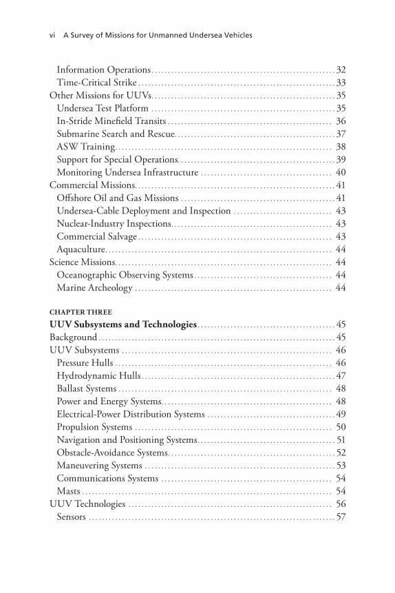
vi A Survey of Missions for Unmanned Undersea Vehicles
Information Operations . . . . . . . . . . . . . . . . . . . . . . . . . . . . . . . . . . . . . . . . . . . . . . . . . . . . . . . . 32Time-Critical Strike . . . . . . . . . . . . . . . . . . . . . . . . . . . . . . . . . . . . . . . . . . . . . . . . . . . . . . . . . . . . 33
Other Missions for UUVs . . . . . . . . . . . . . . . . . . . . . . . . . . . . . . . . . . . . . . . . . . . . . . . . . . . . . . . . 35Undersea Test Platform . . . . . . . . . . . . . . . . . . . . . . . . . . . . . . . . . . . . . . . . . . . . . . . . . . . . . . . . 35In-Stride Minefield Transits . . . . . . . . . . . . . . . . . . . . . . . . . . . . . . . . . . . . . . . . . . . . . . . . . . 36Submarine Search and Rescue . . . . . . . . . . . . . . . . . . . . . . . . . . . . . . . . . . . . . . . . . . . . . . . . . 37ASW Training . . . . . . . . . . . . . . . . . . . . . . . . . . . . . . . . . . . . . . . . . . . . . . . . . . . . . . . . . . . . . . . . . . 38Support for Special Operations. . . . . . . . . . . . . . . . . . . . . . . . . . . . . . . . . . . . . . . . . . . . . . . . 39Monitoring Undersea Infrastructure . . . . . . . . . . . . . . . . . . . . . . . . . . . . . . . . . . . . . . . . 40
Commercial Missions . . . . . . . . . . . . . . . . . . . . . . . . . . . . . . . . . . . . . . . . . . . . . . . . . . . . . . . . . . . . . 41Offshore Oil and Gas Missions . . . . . . . . . . . . . . . . . . . . . . . . . . . . . . . . . . . . . . . . . . . . . . . 41Undersea-Cable Deployment and Inspection . . . . . . . . . . . . . . . . . . . . . . . . . . . . . . 43Nuclear-Industry Inspections . . . . . . . . . . . . . . . . . . . . . . . . . . . . . . . . . . . . . . . . . . . . . . . . . 43Commercial Salvage . . . . . . . . . . . . . . . . . . . . . . . . . . . . . . . . . . . . . . . . . . . . . . . . . . . . . . . . . . . 43Aquaculture . . . . . . . . . . . . . . . . . . . . . . . . . . . . . . . . . . . . . . . . . . . . . . . . . . . . . . . . . . . . . . . . . . . . . 44
Science Missions . . . . . . . . . . . . . . . . . . . . . . . . . . . . . . . . . . . . . . . . . . . . . . . . . . . . . . . . . . . . . . . . . . 44Oceanographic Observing Systems . . . . . . . . . . . . . . . . . . . . . . . . . . . . . . . . . . . . . . . . . . 44Marine Archeology . . . . . . . . . . . . . . . . . . . . . . . . . . . . . . . . . . . . . . . . . . . . . . . . . . . . . . . . . . . . 44
ChAPTer Three
UUV Subsystems and Technologies . . . . . . . . . . . . . . . . . . . . . . . . . . . . . . . . . . . . . . . . . . 45Background . . . . . . . . . . . . . . . . . . . . . . . . . . . . . . . . . . . . . . . . . . . . . . . . . . . . . . . . . . . . . . . . . . . . . . . . 45UUV Subsystems . . . . . . . . . . . . . . . . . . . . . . . . . . . . . . . . . . . . . . . . . . . . . . . . . . . . . . . . . . . . . . . . 46
Pressure Hulls . . . . . . . . . . . . . . . . . . . . . . . . . . . . . . . . . . . . . . . . . . . . . . . . . . . . . . . . . . . . . . . . . . 46Hydrodynamic Hulls . . . . . . . . . . . . . . . . . . . . . . . . . . . . . . . . . . . . . . . . . . . . . . . . . . . . . . . . . . . 47Ballast Systems . . . . . . . . . . . . . . . . . . . . . . . . . . . . . . . . . . . . . . . . . . . . . . . . . . . . . . . . . . . . . . . . . 48Power and Energy Systems . . . . . . . . . . . . . . . . . . . . . . . . . . . . . . . . . . . . . . . . . . . . . . . . . . . . 48Electrical-Power Distribution Systems . . . . . . . . . . . . . . . . . . . . . . . . . . . . . . . . . . . . . . . 49Propulsion Systems . . . . . . . . . . . . . . . . . . . . . . . . . . . . . . . . . . . . . . . . . . . . . . . . . . . . . . . . . . . . 50Navigation and Positioning Systems . . . . . . . . . . . . . . . . . . . . . . . . . . . . . . . . . . . . . . . . . . 51Obstacle-Avoidance Systems . . . . . . . . . . . . . . . . . . . . . . . . . . . . . . . . . . . . . . . . . . . . . . . . . . . 52Maneuvering Systems . . . . . . . . . . . . . . . . . . . . . . . . . . . . . . . . . . . . . . . . . . . . . . . . . . . . . . . . . . 53Communications Systems . . . . . . . . . . . . . . . . . . . . . . . . . . . . . . . . . . . . . . . . . . . . . . . . . . . . 54Masts . . . . . . . . . . . . . . . . . . . . . . . . . . . . . . . . . . . . . . . . . . . . . . . . . . . . . . . . . . . . . . . . . . . . . . . . . . . . 54
UUV Technologies . . . . . . . . . . . . . . . . . . . . . . . . . . . . . . . . . . . . . . . . . . . . . . . . . . . . . . . . . . . . . . 56Sensors . . . . . . . . . . . . . . . . . . . . . . . . . . . . . . . . . . . . . . . . . . . . . . . . . . . . . . . . . . . . . . . . . . . . . . . . . . . 57

Contents vii
Communications and Networking . . . . . . . . . . . . . . . . . . . . . . . . . . . . . . . . . . . . . . . . . . 60Navigation . . . . . . . . . . . . . . . . . . . . . . . . . . . . . . . . . . . . . . . . . . . . . . . . . . . . . . . . . . . . . . . . . . . . . . . 61Energy and Propulsion . . . . . . . . . . . . . . . . . . . . . . . . . . . . . . . . . . . . . . . . . . . . . . . . . . . . . . . . . 63Autonomy . . . . . . . . . . . . . . . . . . . . . . . . . . . . . . . . . . . . . . . . . . . . . . . . . . . . . . . . . . . . . . . . . . . . . . . 64Structure . . . . . . . . . . . . . . . . . . . . . . . . . . . . . . . . . . . . . . . . . . . . . . . . . . . . . . . . . . . . . . . . . . . . . . . . . 65Mission Equipment . . . . . . . . . . . . . . . . . . . . . . . . . . . . . . . . . . . . . . . . . . . . . . . . . . . . . . . . . . . . 66Host Interface . . . . . . . . . . . . . . . . . . . . . . . . . . . . . . . . . . . . . . . . . . . . . . . . . . . . . . . . . . . . . . . . . . 66
UUV Reliability . . . . . . . . . . . . . . . . . . . . . . . . . . . . . . . . . . . . . . . . . . . . . . . . . . . . . . . . . . . . . . . . . . 66
ChAPTer FOUr
evaluation of UUV Missions . . . . . . . . . . . . . . . . . . . . . . . . . . . . . . . . . . . . . . . . . . . . . . . . . . 69The DoD’s Unmanned Systems Roadmap (2007–2032) . . . . . . . . . . . . . . . . . . . . . . . 69Intelligence, Surveillance, and Reconnaissance . . . . . . . . . . . . . . . . . . . . . . . . . . . . . . . 70
Persistent and Tactical Intelligence Collection . . . . . . . . . . . . . . . . . . . . . . . . . . . . . . 71CBNRE Detection and Localization . . . . . . . . . . . . . . . . . . . . . . . . . . . . . . . . . . . . . . . . . 75Near-Land and Harbor Monitoring . . . . . . . . . . . . . . . . . . . . . . . . . . . . . . . . . . . . . . . . . . 76Deployment of Leave-Behind Systems . . . . . . . . . . . . . . . . . . . . . . . . . . . . . . . . . . . . . . 77Specialized Mapping and Object Detection and Localization . . . . . . . . . . . . 81
Mine Countermeasures . . . . . . . . . . . . . . . . . . . . . . . . . . . . . . . . . . . . . . . . . . . . . . . . . . . . . . . . . . . 81Anti-Submarine Warfare . . . . . . . . . . . . . . . . . . . . . . . . . . . . . . . . . . . . . . . . . . . . . . . . . . . . . . . . 84
Hold at Risk . . . . . . . . . . . . . . . . . . . . . . . . . . . . . . . . . . . . . . . . . . . . . . . . . . . . . . . . . . . . . . . . . . . . . 85Maritime Shield . . . . . . . . . . . . . . . . . . . . . . . . . . . . . . . . . . . . . . . . . . . . . . . . . . . . . . . . . . . . . . . . 87Protected Passage. . . . . . . . . . . . . . . . . . . . . . . . . . . . . . . . . . . . . . . . . . . . . . . . . . . . . . . . . . . . . . . 88
Inspection/Identification . . . . . . . . . . . . . . . . . . . . . . . . . . . . . . . . . . . . . . . . . . . . . . . . . . . . . . . . 90Oceanography . . . . . . . . . . . . . . . . . . . . . . . . . . . . . . . . . . . . . . . . . . . . . . . . . . . . . . . . . . . . . . . . . . . . . 91Communications/Navigation Network Nodes . . . . . . . . . . . . . . . . . . . . . . . . . . . . . . . . 91Payload Delivery . . . . . . . . . . . . . . . . . . . . . . . . . . . . . . . . . . . . . . . . . . . . . . . . . . . . . . . . . . . . . . . . . . 93Information Operations . . . . . . . . . . . . . . . . . . . . . . . . . . . . . . . . . . . . . . . . . . . . . . . . . . . . . . . . . 94
Network Information Operations . . . . . . . . . . . . . . . . . . . . . . . . . . . . . . . . . . . . . . . . . . . . 95Decoy Operations . . . . . . . . . . . . . . . . . . . . . . . . . . . . . . . . . . . . . . . . . . . . . . . . . . . . . . . . . . . . . . 96
Time-Critical Strike . . . . . . . . . . . . . . . . . . . . . . . . . . . . . . . . . . . . . . . . . . . . . . . . . . . . . . . . . . . . . 97Undersea Test Platforms . . . . . . . . . . . . . . . . . . . . . . . . . . . . . . . . . . . . . . . . . . . . . . . . . . . . . . . . 100Submarine Search and Rescue . . . . . . . . . . . . . . . . . . . . . . . . . . . . . . . . . . . . . . . . . . . . . . . . . 101ASW Training . . . . . . . . . . . . . . . . . . . . . . . . . . . . . . . . . . . . . . . . . . . . . . . . . . . . . . . . . . . . . . . . . . . 101Monitoring Undersea Infrastructure . . . . . . . . . . . . . . . . . . . . . . . . . . . . . . . . . . . . . . . . . . 101

viii A Survey of Missions for Unmanned Undersea Vehicles
ChAPTer FIVe
Summary and recommendations . . . . . . . . . . . . . . . . . . . . . . . . . . . . . . . . . . . . . . . . . . 103Unmanned Maritime System Master Plans and Roadmaps . . . . . . . . . . . . . . . 104Missions from the 2004 UUV Master Plan . . . . . . . . . . . . . . . . . . . . . . . . . . . . . . . . . . 107Unmanned Maritime System Programs . . . . . . . . . . . . . . . . . . . . . . . . . . . . . . . . . . . . . . 108Recommendations . . . . . . . . . . . . . . . . . . . . . . . . . . . . . . . . . . . . . . . . . . . . . . . . . . . . . . . . . . . . . . 111
Main Recommendations . . . . . . . . . . . . . . . . . . . . . . . . . . . . . . . . . . . . . . . . . . . . . . . . . . . . . 111Other Recommendations . . . . . . . . . . . . . . . . . . . . . . . . . . . . . . . . . . . . . . . . . . . . . . . . . . . . 112
APPenDIxeS
A. UUV Market Survey . . . . . . . . . . . . . . . . . . . . . . . . . . . . . . . . . . . . . . . . . . . . . . . . . . . . . . . 115B. Models Used in This Analysis and Their Implications . . . . . . . . . . . . . . 179
Bibliography . . . . . . . . . . . . . . . . . . . . . . . . . . . . . . . . . . . . . . . . . . . . . . . . . . . . . . . . . . . . . . . . . . . . 183

ix
Figures
2.1. Task Force ASW Missions . . . . . . . . . . . . . . . . . . . . . . . . . . . . . . . . . . . . . . . . . 22 2.2. Baseline Hold-at-Risk ASW CONOP . . . . . . . . . . . . . . . . . . . . . . . . . . . 22 2.3. Multi-UUV Hold-at-Risk ASW CONOP . . . . . . . . . . . . . . . . . . . . . . 23 4.1. AN/WQR-3 Advanced Distributed System . . . . . . . . . . . . . . . . . . . . . . 78 4.2. Array Installation Module and Dispenser Transport
Vehicle . . . . . . . . . . . . . . . . . . . . . . . . . . . . . . . . . . . . . . . . . . . . . . . . . . . . . . . . . . . . . . . . . 79 4.3. DTV Deployment . . . . . . . . . . . . . . . . . . . . . . . . . . . . . . . . . . . . . . . . . . . . . . . . . . 80 4.4. UUV Effectiveness in Hold at Risk . . . . . . . . . . . . . . . . . . . . . . . . . . . . . . 86 4.5. The Jianggezhuang Submarine Base . . . . . . . . . . . . . . . . . . . . . . . . . . . . . . 87 5.1. DoD Funding for Unmanned Systems . . . . . . . . . . . . . . . . . . . . . . . . . 109 A.1. REMUS 100 . . . . . . . . . . . . . . . . . . . . . . . . . . . . . . . . . . . . . . . . . . . . . . . . . . . . . . . 117 A.2. Bluefin-9 . . . . . . . . . . . . . . . . . . . . . . . . . . . . . . . . . . . . . . . . . . . . . . . . . . . . . . . . . . . . 119 A.3. Flying Plug . . . . . . . . . . . . . . . . . . . . . . . . . . . . . . . . . . . . . . . . . . . . . . . . . . . . . . . . . . 121 A.4. REMUS 6000 Components . . . . . . . . . . . . . . . . . . . . . . . . . . . . . . . . . . . . . . 127 A.5. Bluefin-21 Modular Design . . . . . . . . . . . . . . . . . . . . . . . . . . . . . . . . . . . . . . 134 A.6. Bluefin-21 BPAUV . . . . . . . . . . . . . . . . . . . . . . . . . . . . . . . . . . . . . . . . . . . . . . . . . 136 A.7. HUGIN 3000 . . . . . . . . . . . . . . . . . . . . . . . . . . . . . . . . . . . . . . . . . . . . . . . . . . . . . . 139 A.8. A Typical HUGIN 1000 Configuration . . . . . . . . . . . . . . . . . . . . . . . . 140 A.9. AUSS . . . . . . . . . . . . . . . . . . . . . . . . . . . . . . . . . . . . . . . . . . . . . . . . . . . . . . . . . . . . . . . . 144 A.10. AUSS Image of a Skyraider Aircraft . . . . . . . . . . . . . . . . . . . . . . . . . . . . . 145 A.11. Theseus . . . . . . . . . . . . . . . . . . . . . . . . . . . . . . . . . . . . . . . . . . . . . . . . . . . . . . . . . . . . . . . 147 A.12. Seahorse . . . . . . . . . . . . . . . . . . . . . . . . . . . . . . . . . . . . . . . . . . . . . . . . . . . . . . . . . . . . . 150 A.13. Spray Glider . . . . . . . . . . . . . . . . . . . . . . . . . . . . . . . . . . . . . . . . . . . . . . . . . . . . . . . . 154 A.14. Seaglider . . . . . . . . . . . . . . . . . . . . . . . . . . . . . . . . . . . . . . . . . . . . . . . . . . . . . . . . . . . . 157 A.15. Seaglider with Mast Exposed . . . . . . . . . . . . . . . . . . . . . . . . . . . . . . . . . . . . . 157 A.16. VideoRay Pro 3 XEGTO System . . . . . . . . . . . . . . . . . . . . . . . . . . . . . . . . 161 A.17. Panther with Pipe-Following Wheels . . . . . . . . . . . . . . . . . . . . . . . . . . . 164

x A Survey of Missions for Unmanned Undersea Vehicles
A.18. Panther Plus . . . . . . . . . . . . . . . . . . . . . . . . . . . . . . . . . . . . . . . . . . . . . . . . . . . . . . . . 165 A.19. Super Scorpio with Recovered Flight Recorder . . . . . . . . . . . . . . . . 167 A.20. Double Eagle MK-III. . . . . . . . . . . . . . . . . . . . . . . . . . . . . . . . . . . . . . . . . . . . . . 168 A.21. The Transphibian . . . . . . . . . . . . . . . . . . . . . . . . . . . . . . . . . . . . . . . . . . . . . . . . . . 171 A.22. Robotuna II . . . . . . . . . . . . . . . . . . . . . . . . . . . . . . . . . . . . . . . . . . . . . . . . . . . . . . . . 171 A.23. Robolobsters . . . . . . . . . . . . . . . . . . . . . . . . . . . . . . . . . . . . . . . . . . . . . . . . . . . . . . . . 172 A.24. The AN/WLD-1 RMS in Operation . . . . . . . . . . . . . . . . . . . . . . . . . . . . 174 A.25. RMV . . . . . . . . . . . . . . . . . . . . . . . . . . . . . . . . . . . . . . . . . . . . . . . . . . . . . . . . . . . . . . . . 175 A.26. AN/AQS-20 VDS. . . . . . . . . . . . . . . . . . . . . . . . . . . . . . . . . . . . . . . . . . . . . . . . . . 176 A.27. Schematic Representation of the RMS CONOP . . . . . . . . . . . . . . 177

xi
Tables
2.1. Notional Capabilities for ISR . . . . . . . . . . . . . . . . . . . . . . . . . . . . . . . . . . . . . . 15 2.2. Notional Capabilities for Hold-at-Risk ASW . . . . . . . . . . . . . . . . . . . . 21 2.3. Notional Capabilities for CN3 . . . . . . . . . . . . . . . . . . . . . . . . . . . . . . . . . . . . 28 2.4. AUVs Operated by the Offshore Oil and Gas Industry . . . . . . . . 42 A.1. Vehicle Classes from the 2004 UUV Master Plan . . . . . . . . . . . . . 116 A.2. REMUS 100 Main Specifications . . . . . . . . . . . . . . . . . . . . . . . . . . . . . . . 118 A.3. Bluefin-9 Main Specifications . . . . . . . . . . . . . . . . . . . . . . . . . . . . . . . . . . . . 120 A.4. Flying Plug Main Specifications . . . . . . . . . . . . . . . . . . . . . . . . . . . . . . . . . 122 A.5. Bluefin-12 Main Specifications . . . . . . . . . . . . . . . . . . . . . . . . . . . . . . . . . . . 123 A.6. SMCM UUV Increment 2 Main Specifications . . . . . . . . . . . . . . . 124 A.7. REMUS 600 Main Specifications . . . . . . . . . . . . . . . . . . . . . . . . . . . . . . . 125 A.8. REMUS 3000 Main Specifications . . . . . . . . . . . . . . . . . . . . . . . . . . . . . 126 A.9. REMUS 6000 Main Specifications . . . . . . . . . . . . . . . . . . . . . . . . . . . . . 127 A.10. LMRS Main Specifications . . . . . . . . . . . . . . . . . . . . . . . . . . . . . . . . . . . . . . . 130 A.11. Planned MRUUVS Characteristics . . . . . . . . . . . . . . . . . . . . . . . . . . . . . 133 A.12. Bluefin-21 Main Specifications . . . . . . . . . . . . . . . . . . . . . . . . . . . . . . . . . . . 135 A.13. Bluefin-21 BPAUV Main Specifications . . . . . . . . . . . . . . . . . . . . . . . . 137 A.14. SMCM UUV Increment 3 Main Specifications . . . . . . . . . . . . . . . 138 A.15. HUGIN 3000 Main Specifications . . . . . . . . . . . . . . . . . . . . . . . . . . . . . 139 A.16. HUGIN 1000 Military Version Main Specifications . . . . . . . . . 141 A.17. AUSS Main Specifications . . . . . . . . . . . . . . . . . . . . . . . . . . . . . . . . . . . . . . . . 145 A.18. Aqua Explorer 2000 Main Specifications . . . . . . . . . . . . . . . . . . . . . . . 146 A.19. Theseus Main Specifications . . . . . . . . . . . . . . . . . . . . . . . . . . . . . . . . . . . . . . . 148 A.20. Seahorse Main Specifications . . . . . . . . . . . . . . . . . . . . . . . . . . . . . . . . . . . . . 150 A.21. Spray Main Specifications . . . . . . . . . . . . . . . . . . . . . . . . . . . . . . . . . . . . . . . . 154 A.22. Slocum Battery Glider Main Specifications . . . . . . . . . . . . . . . . . . . . 156 A.23. Seaglider Main Specifications . . . . . . . . . . . . . . . . . . . . . . . . . . . . . . . . . . . . 158
xii A Survey of Missions for Unmanned Undersea Vehicles
A.24. SAUV II Main Specifications . . . . . . . . . . . . . . . . . . . . . . . . . . . . . . . . . . . . 160 A.25. NURC Phantom S2 Main Specifications . . . . . . . . . . . . . . . . . . . . . . . 162 A.26. Stingray Main Specifications . . . . . . . . . . . . . . . . . . . . . . . . . . . . . . . . . . . . . 163 A.27. Panther Main Specifications . . . . . . . . . . . . . . . . . . . . . . . . . . . . . . . . . . . . . . 164 A.28. Panther Plus Main Specifications . . . . . . . . . . . . . . . . . . . . . . . . . . . . . . . . 165 A.29. AN/WLD-1 RMS Main Specifications . . . . . . . . . . . . . . . . . . . . . . . . . 174

xiii
Summary
Background
The question central to this book is, Which missions for UUVs appear most promising to pursue in terms of military need, risk, alternatives, and cost? This question subsumes the following questions:
What missions are advocated for UUVs?•How great is the military need for these missions?•What are the technical risks associated with developing UUVs for •these missions? What are the operational risks of using UUVs for these missions?What, if any, are the alternatives to UUVs in conducting these •missions? For example, would these missions be better performed by manned systems, semisubmersible unmanned vehicles, or fixed systems?What would be the cost of using UUVs to conduct these missions? •For which missions are UUVs the most cost-effective alternative?
In examining military missions advocated for UUVs, we identi-fied an unwieldy mission set: more than 40 distinct missions for UUVs are advocated in the Navy’s 2004 UUV Master Plan alone. Using the Sea Power 21 construct as guidance, the master plan defines nine mis-sion categories for UUVs and prioritizes them in the following order:
Intelligence, Surveillance, and Reconnaissance (ISR)1. Mine Countermeasures (MCM)2. Anti-Submarine Warfare (ASW)3.
xiv A Survey of Missions for Unmanned Undersea Vehicles
Inspection/Identification4. Oceanography5. Communications/Navigation Network Node (CN3)6. Payload Delivery7. Information Operations8. Time Critical Strike (TCS).9. 1
Focusing on the highest priority mission category, ISR, the 2004 UUV Master Plan advocates the following possible ISR UUV missions:
Persistent and tactical intelligence collection: Signal, Elec-•tronic, Measurement, and Imaging Intelligence (SIGINT, ELINT, MASINT, and IMINT), Meteorology and Oceanography (METOC), etc. (above and/or below ocean surface)Chemical, Biological, Nuclear, Radiological, and Explo-•sive (CBNRE) detection and localization (both above and below the ocean surface)Near-Land and Harbor Monitoring•Deployment of leave-behind surveillance sensors or sensor •arraysSpecialized mapping and object detection and •localization.2
Operational need varies across these missions. For example, there is no need or advantage in using UUVs to collect atmospheric data (i.e., meteorology above the ocean surface). Similarly, endurance and other requirements for UUVs in tactical and persistent intelligence-collection missions differ.3 Vehicle size and sensor capability require-ments will likely vary across these missions. The missions also require
1 U.S. Department of the Navy, The Navy Unmanned Undersea Vehicle (UUV) Master Plan, November 2004, p. 16.2 U.S. Department of the Navy, 2004, p. 9.3 Endurance for tactical ISR missions is projected to be less than 100 hours; endurance for persistent ISR missions is projected to exceed 300 hours (U.S. Department of the Navy, 2004, p. 22). The radius of operation for tactical ISR missions is projected to be 50–75 nm;

Summary xv
differing levels of UUV autonomy (loosely, the ability to accomplish mission tasks, such as vehicle movement and data collection, without human intervention). Alternatives to UUVs also differ by mission. For example, USVs might be attractive (or even preferred) for missions requiring continuous mast exposure but may be considered unsuitable for other missions. In short, an analysis of UUV need, risks, alterna-tives, and cost cannot be carried out at the level of the nine mission cat-egories. Consequently, this study required examination of more than 40 distinct advocated UUV missions, each of which is tied back to one of the nine parent missions. This unwieldy mission set limited the depth to which we could evaluate UUV missions, and our efforts were further hampered by the fact that many missions are not well defined. For example, the 2004 UUV Master Plan does not discuss the duration or objectives of imaging intelligence missions, nor does it identify such requirements as onboard image processing and communications.
Our assessment of need was based to the extent possible on material provided by the Assessment Division, Office of the Chief of Naval Operations (OPNAV N81) on warfighter needs in the near and medium terms. We also interviewed operators to assess need. We found that the best match between warfighter needs and UUV capabilities is in MCM missions.
Risk in general could only be judged broadly. The absence in many cases of clearly defined operational objectives made it difficult to assess risk. Also, roughly half of the advocated missions are novel in the sense that no research and development efforts have been applied spe-cifically to them. Absent preliminary research and development efforts, technical risk is unclear.
Limited availability of cost data also hindered this study. Most available UUV cost data relate to small-production vehicles or to larger prototype vehicles. Experienced RAND cost analysts could find no cost estimates for the relatively large and complex vehicles needed for many advocated missions. Extrapolation of costs from relatively small
the radius of operation for persistent ISR missions is projected to be at least twice that distance.

xvi A Survey of Missions for Unmanned Undersea Vehicles
and simple vehicles to relatively large and complex vehicles was deemed unwise.
In short, this roughly six-month research effort could not answer the study question with the depth and thoroughness desired. When identified, showstoppers (such as illegality, absence of need, or dis-qualifying technical or operational risks4) were flagged without further consideration in order to conserve study resources.
Recommended Missions
Based on this study, RAND recommends the following seven mission categories for UUVs.
MCM. The need for additional MCM capability within the U.S. Navy has been demonstrated by OPNAV N81 studies that show that the greatest need for such capability is in denied areas. MCM operations in denied areas can be conducted by launching autonomous under-sea vehicles (AUVs)5 from nuclear attack submarines (SSNs) operating within the denied areas or by launching longer-endurance AUVs from surface ships operating outside denied areas. Several new or emerg-ing technologies promise to provide the endurance needed for MCM operations in denied areas using surface ships. Both the U.S. Navy and foreign navies have made significant progress in developing UUVs for MCM. Significantly, several foreign navies have fielded UUVs for MCM from surface ships. UUV capabilities and cost effectiveness have been demonstrated for this mission.
4 For example, the TCS mission as proposed violates the Strategic Arms Reduction Treaty. The use of AUVs as lane markers for amphibious operations under CN3 missions was strongly rejected by Marines we interviewed. Some missions required order-of-magnitude technology improvements deemed unachievable in the near to medium terms. Operational concepts for some proposed ASW missions for UUVs do not provide critical kill chains.5 AUVs are unoccupied submersibles (without tethers) that are powered by onboard batter-ies, fuel cells, or other energy sources. AUVs are intended to carry out preprogrammed mis-sions with little or no direct human intervention (see Committee on Undersea Vehicles and National Needs National Research Council, Undersea Vehicles and National Needs, National Academies Press, 1996).

Summary xvii
Missions to deploy leave-behind surveillance sensors or sensor arrays. The need for these missions is based on classified material con-tained in unpublished RAND Corporation research produced under the auspices of this study. The vehicle payload-capacity requirements for these missions are consistent with the payload capacities of AUVs now in development. The feasibility of deploying leave-behind acous-tic arrays has been demonstrated by the Advanced Distributed System (ADS), which uses AUVs to deploy its sensor arrays. The level of auton-omy required to emplace leave-behind sensors or sensor arrays has been further demonstrated by commercial systems capable of autono-mously laying undersea cables or determining pipeline routes for com-mercial gas and oil developers. Also, autonomy requirements may be reduced when AUVs are directed to deploy packages at specified loca-tions, such as outside ports. The alternative to an unmanned system for these missions is, by definition, a manned system, such as the Sea-Air-Land (SEAL) Delivery Vehicle (SDV) or the Advanced SEAL Delivery System (ASDS). Both the SDV and the ASDS depend on nuclear sub-marines for transportation into a theater, which limits mission respon-siveness and the rate at which missions can be performed. Using SEALs to emplace packages in sensitive regions also entails human risk. The simplicity of the AUV used to deploy ADS arrays and the existence of commercial AUVs large enough to deploy a variety of surveillance sensors or sensor arrays suggest that AUVs for this mission would be affordable.
near-land and harbor-monitoring missions. These missions could provide protection for special operations forces (SOF) in over-the-beach operations by (1) identifying areas with the lowest activity levels, (2) warning SOF operators of possible threats of detection, and (3) providing overwatch for caches of supplies and equipment as SOF operators conduct missions inland. Need for this mission is seen in the context of increasing dependence on SOF operations in countering militant extremists. The ability to conduct near-land and harbor moni-toring for over-the-beach special operations was demonstrated in 2003 during Exercise Giant Shadow, suggesting that technical and opera-tional risks for this mission are low. No manned- or fixed-system alter-natives to AUVs are evident. The Navy has acquired several AUVs like

xviii A Survey of Missions for Unmanned Undersea Vehicles
the one used to demonstrate near-land and harbor monitoring for other missions. Although the cost of this vehicle is unknown, it is clearly affordable.
Oceanography missions. Gliders—AUVs notable for their endurance—can gather tactically useful oceanographic data under adverse weather conditions and significantly enhance the quality and quantity of oceanographic data available to warfighters. Gliders used today for oceanography cost only tens of thousands of dollars, can col-lect oceanographic data continuously while deployed for months at a time, and can be refueled at minimal cost. They are cheap enough to be considered expendable. Gliders being tested today are designed to last for years, during which time they could continually collect oceano-graphic data. The use of gliders in oceanography missions should be pursued.
Monitoring undersea infrastructure. The U.S. military depends on an extensive infrastructure of undersea communications cables, the Integrated Undersea Surveillance System, and instrumented under-sea ranges. Undersea communications cables are critical because the alternative, satellite communications, provides only a fraction of the bandwidth of fiber-optic cables. However, undersea communications systems are vulnerable to the inevitable effects of aging and marine life, anchors, fishing nets, and malfeasance. (Note that the locations of undersea communications systems are public knowledge.) The risk associated with using AUVs to monitor undersea systems is consid-ered low. To illustrate, in the summer of 1999, the Kokusai Marine Engineering Corporation used an AUV to inspect over 200 miles of undersea cable that crosses the Taiwan Strait. The survey produced a complete video recording of the cable and the surrounding seabed. A more-capable vehicle has since replaced the AUV used in this effort. Manned vehicles are the only alternative to unmanned vehicles for this type of monitoring mission. NR-1, the Navy’s only nuclear deep-diving research submarine, is capable of this mission, but it was deactivated in November 2008. There is no plan to replace NR-1 with another deep-diving submarine, and no other Navy vessel can conduct this mission. On the topic of cost, note that because undersea-cable inspection is a

Summary xix
small but successful industry, this mission could be conducted via con-tract or the purchase or lease of an existing AUV.
ASw tracking missions. The need for ASW tracking missions, which detect the movement of potential adversary submarines out of port and possibly track their subsequent movements, has been debated as the U.S. Navy evolves its ASW concepts. If ASW tracking missions are needed, we believe that they could be conducted with AUVs. AUVs able to detect and classify threat submarines are being developed, and propulsion systems that enable tracking operations appear feasible. One such vehicle is now being tested. Technical risk is mitigated by developers’ varied technological approaches, which include the use of novel sensors. SSNs, the only known alternative to AUVs for this mis-sion, must operate undetected off enemy ports. Los Angeles (SSN-688)–class SSNs are the backbone of today’s submarine force, and a total of 62 Los Angeles–class SSNs entered service between 1976 and 1996. Remaining Los Angeles–class SSNs will begin undergoing block obso-lescence in the coming decade, however, and the procurement rate of Virginia (SSN-774)–class SSNs is not expected to maintain the current SSN force level. As the SSN force level declines significantly begin-ning in approximately 2015, using AUVs to perform relatively routine tasks (such as tracking threatening submarines) could free remaining U.S. SSNs for more-critical missions. If ASW tracking missions are indeed needed, we recommend that further development of AUVs for this mission be pursued in order to better understand their associated capabilities, costs, and risks.
Inspection/identification missions. These missions support homeland defense and antiterrorism/force protection needs through the inspection of ship hulls and piers for foreign objects (such as limpet mines and special attack charges). Inspection/identification also includes common activities such as underwater hull survey, ship hus-bandry, and repair. The need for identification/inspection missions will be long-standing. Terrorist threats against U.S. vessels are a real threat, as demonstrated by the attack on the USS Cole. Inspection/identifica-tion missions of both military and commercial vessels are increasingly being performed by UUVs instead of divers. Experience has demon-

xx A Survey of Missions for Unmanned Undersea Vehicles
strated the cost effectiveness of using UUVs for inspection/identifica-tion missions.
UUVs and UUV Technologies
N81 also asked RAND to describe UUVs of interest and UUV tech-nologies. We cannot summarize here all of the technical information presented later in this book, but we do wish to draw attention to the following technical findings:
Autonomy in complex missions may include such tasks as judg-•ing the import of collected intelligence, developing hypotheses and plans to test them, and developing situational awareness for self-protection.6 Situational awareness will be needed in order for AUVs to operate in high-threat areas or areas where there is a high risk of incidental detection (e.g., visual detection by fishermen). There is a high level of technological risk in developing AUVs to autonomously conduct complex SIGINT, ELINT, MASINT, and IMINT missions.7 The current state of AUV autonomous capa-bility for ISR is reflected in AUVs’ imperfect ability to recognize
6 A survey of AUV developers conducted by the Association for Unmanned Vehicle Sys-tems International and RAND in the spring of 2008 revealed that autonomy will be the greatest long-term challenge to the development of AUVs.7 Office of the Secretary of Defense, Joint Publication 1-02, Dictionary of Military and Asso-ciated Terms, April 12, 2001, as amended through June 13, 2007a, defines SIGINT as a cat-egory of intelligence comprising either individually or in combination all communications intelligence, ELINT, and foreign instrumentation SIGINT, however transmitted. ELINT is defined as technical and geolocation intelligence derived from foreign noncommunications electromagnetic radiations emanating from sources other than nuclear detonations or radio-active matter. MASINT is defined as technically derived intelligence that detects, locates, tracks, identifies, and describes the unique characteristics of fixed and dynamic target sources. MASINT capabilities include radar, laser, optical, infrared, acoustic, nuclear radia-tion, radio frequency, spectroradiometric, and seismic sensing systems as well as gas, liquid, and solid-materials sampling and analysis. IMINT is defined as the technical, geographic, and intelligence information derived through the interpretation or analysis of imagery and collateral materials. We note that although the 2004 UUV Master Plan treats SIGINT and ELINT as separate forms of intelligence, SIGINT is in fact a form of ELINT.

Summary xxi
sailboats and their limited ability to recognize military vessels by their profiles.8 Giant strides would be required to autonomously detect significant ship alterations, for example. We also observe that future autonomy performance will be limited by the AUVs’ onboard computational power (which may be similar to levels found in most personal computers). For the foreseeable future, the development of autonomy needed for complex ISR missions, such as tactical SIGINT, will be highly technically challenging. Moreover, the ability to deal with unforeseen conditions, espe-cially in complex environments, demands still more autonomy from AUVs. This is especially true in covert or clandestine AUV missions during which mission failure, loss of clandestine cover, and vehicle exploitation by adversaries are issues. Whereas AUVs conducting missions such as oceanography can deballast, return to the surface, and signal for help under conditions they cannot manage, AUVs in covert or clandestine missions have no such options. This is a broad and serious issue for advocated ISR mis-sions for AUVs.Autonomy and communications bandwidth form a tradespace. •However, communications bandwidth is limited, and the com-munications options open to AUVs tend to be slow. Moreover, stealth issues are associated with operating AUVs with masts exposed and broadcasting for long periods of time. These stealth issues can spill over to host vessels, such as SSNs.The second-greatest long-term technical challenge to AUV devel-•opment is in the area of propulsion energy. Propulsion objectives stated in the 2004 UUV Master Plan would require order-of-magnitude improvements in propulsion technology. Such perfor-mance improvements may not come from spiral development of existing propulsion technologies.There are attractive and less-risky alternatives (such as USVs and •unmanned aerial vehicles) for most of the ISR missions advocated
8 Paul R. Arrieta, F. Chandler, F. Crosby, and J. Purpura, “Above Water Obstacle Detec-tion for the Remote Minehunting System (RMS),” Naval Surface Warfare Center, briefing presented at the ONR/AUVSI Joint Review, Orlando, Fla., February 12, 2008.
xxii A Survey of Missions for Unmanned Undersea Vehicles
for UUVs. On the topic of ISR missions, the Navy’s USV Master Plan notes, “While the UUV option provides stealth beyond that associated with a USV, Semi-Submersible Vehicles (SSVs) can provide a nearly identical stealth profile, given that the ISR mis-sion by definition requires extensive mast or antenna exposure.”9 The USV Master Plan also notes advantages for USVs in terms of availability, retasking, and persistence.The development of AUVs to be launched from SSN torpedo tubes •is difficult and requires design compromises. For AUVs launched from torpedo tubes, the Naval Undersea Warfare Center of the Naval Sea Systems Command has described restrictions and requirements in the areas of start-up, weight and volume, neu-tral buoyancy, gas evolution and noise signature, safety, fuel and oxidizer choices, refueling, logistic fuels/sulfur, temperature, and endurance.10 Implodable volume has also been cited as a certifica-tion issue. To this we add that the torpedo rooms of Los Angeles– and Virginia-class SSNs lack electrical-power distribution systems needed to recharge large, battery-powered AUVs. These inher-ent problems imply design compromises and additional costs for AUVs launched from torpedo tubes.
Other Recommendations
Other recommendations from this study treat a specific AUV pro-gram and the Navy’s master plans for UUVs and USVs. The Mission- Reconfigurable Unmanned Undersea Vehicle System (MRUUVS) program is currently intended to develop AUVs that use the torpedo tubes of Los Angeles–class SSNs for launch and recovery. MRUUVS is intended to be modular and have modules for clandestine ISR and MCM missions. Predecessor programs to MRUUVS begun in 1994
9 U.S. Department of the Navy, The Navy Unmanned Surface Vehicle (USV) Master Plan, July 2007b, p. 32.10 Maria G. Medeiros, “Weapons and Vehicles Needs,” briefing presented at CEROS Indus-try Day, Naval Undersea Warfare Center, November 13, 2007.

Summary xxiii
did not address SUBSAFE safety issues or field usable systems.11 The current MRUUVS program also will not address those long-standing safety issues and will not field a usable system by 2013. As noted above, the development of AUVs to be launched from SSN torpedo tubes is difficult and requires design compromises. Los Angeles–class SSNs will undergo block obsolescence before MRUUVS can be fielded, meaning that a reduced number of SSNs will be available to deploy MRUUVS. MRUUVS will be incompatible with Virginia-class SSNs due to dif-ferences in torpedo doors, and further effort will be needed to make MRUUVS usable by Virginia-class SSNs as Los Angeles–class SSNs go out of service. We recommend that the MRUUVS program be can-celled or restructured with achievable, appropriate milestones.
The Navy’s 2004 UUV Master Plan has been described as intended for the blue-water Navy. Several changes are recommended to improve the plan’s broader utility. First, the 2004 UUV Master Plan and the subsequent USV Master Plan should be consolidated into a master plan for unmanned maritime systems (UMSs).12 The 2004 UUV Master Plan and the USV Master Plan are stovepiped and dis-play significant overlap in the missions they advocate for UUVs and USVs. Also, as noted above, the 2004 UUV Master Plan advocates too many missions for UUVs. Scrutiny of previous and projected research and development budgets for UMSs reveals that funding for research and development will be inadequate to develop most advocated UUV missions. It is revealing that the Office of the Secretary of Defense’s Unmanned Systems Roadmap sees only four mission groups for each type of unmanned vehicle (i.e., aerial, ground, surface, and undersea).13 To paraphrase 1993 congressional language, the Office of the Secre-tary of Defense and the Navy should establish priorities among various
11 SUBSAFE is a Navy quality assurance program intended to maintain the safety of the nuclear submarine fleet. All submarine systems exposed to sea pressure as well as those criti-cal to flooding recovery are subject to SUBSAFE requirements. The MRUUVS program and its predecessors use a vehicle-recovery arm that is not certified SUBSAFE. 12 Office of the Secretary of Defense, Unmanned Systems Roadmap (2007–2032), Washing-ton, D.C., December 10, 2007b.13 Office of the Secretary of Defense, 2007b, p. 23.
xxiv A Survey of Missions for Unmanned Undersea Vehicles
proposed UMS programs and establish affordable, cost-effective pro-grams.14 Questions like those addressed in this book should be used to select the most-promising missions for UMSs, and those missions (and their requirements) should be defined in more detail. We add that the Unmanned Systems Roadmap explicitly considers legal and treaty issues in down-selecting missions for unmanned vehicles. We recommend that the Navy adopt this practice.
14 Federation of American Scientists, “UUV Program Plan,” Web page, undated.

xxv
Acknowledgments
From the Applied Research Laboratory (ARL Penn State) at Penn-sylvania State University, we especially thank Dr. Edward G. Liszka for sponsoring extensive discussions with ARL Penn State personnel. We also thank Dr. Victor A. Fishman, Michael J. Pierzga, William Zierche, Leo J. Schneider, Jr., Dr. William L. Kiser, Dr. Mark T. Tra-band, Thomas Hilands, Thomas Lin, Mark Bregar, Tom Cawley, and Charles Brickell, Jr. for the information they provided us and for their participation in thoughtful discussions that illuminated several issues addressed in this book.
From Hydroid, LLC, we thank Christopher von Alt and Robert Brown in particular for their insights into the capabilities of Hydroid vehicles.
From Lockheed Martin, we thank John C. Brandles, B. Casey Campfield, William H. Girodet, Louis J. Larkin, and William Senke for their participation in discussions of manned-vehicle alternatives to UUVs.
From Naval Sea Systems Command, Acoustic Research Detach-ment (NAVSEA 073R), we thank Drew Meyer for clarifying the limi-tations of UUVs as test platforms for larger platforms.
From the Office of Naval Research, we thank Dr. Tom Swean, Dan Dietz, and Dr. Theresa Paluszkiewic for their participation in dis-cussions of UUV issues, especially glider issues, and the Persistent Lit-toral Undersea Surveillance Innovative Naval Prototypes program.
From OPNAV N81, we thank CDR Bryan Clark (ret.), Garth Jensen, CDR E. J. McClure, and CAPT John Yurchak (ret.) for their insights into operational needs.

xxvi A Survey of Missions for Unmanned Undersea Vehicles
From OPNAV N81P1, we thank Pat Madden for improving our understanding of technical issues associated with AUV design.
From PMS 403, we thank LCDR Steve Martin and CAPT John Siegrist for the programmatic information they provided.
From SEAL Delivery Vehicle Team 1, CDR Randy West, LCDR Tom Ryno, Lt Rob Myers, LCDR Greg Parkins, and CDR Curt Ley-shon participated in enlightening discussions of UUV missions of value to SOF and of manned-vehicle alternatives to UUVs.
From the U.S. Marine Corps, Col. Douglas King provided a war-fighter’s perspective on the use of UUVs in amphibious operations.
The assembly of information and ideas needed for the study would not have been possible without the assistance of these people.
Any errors are the responsibility of the authors.
xxvii
Abbreviations
ACINT acoustic intelligence
ACR area coverage rate
ACTD advanced concept technology development
ADS Advanced Distributed System
ADUUV Advanced Development UUV
AIM Array Installation Module
ARL Penn State Applied Research Laboratory, Pennsylvania State University
ASCM anti-ship cruise missile
ASDS Advanced SEAL Delivery System
ASW anti-submarine warfare
AT/FP antiterrorism/force protection
AUSS Advanced Unmanned Search System
AUV autonomous undersea vehicle
AUVSI Association for Unmanned Vehicle Systems International
BAE British Aerospace
BPAUV Battlespace Preparation AUV

xxviii A Survey of Missions for Unmanned Undersea Vehicles
bps bits per second
CAC computer-aided classification
CAD computer-aided detection
CBNRE chemical, biological, nuclear, radiological, and explosive
CN3 communications/navigation network node
CONEMP concept of employment
CONOP concept of operation
COTS commercial off the shelf
CSG carrier strike group
CTD conductivity, temperature, and depth
DC direct current
DDS dry deck shelter
DPCA Displaced Phase Center Antenna
DSRV deep submergence rescue vehicle
DTV Dispenser Transport Vehicle
ELINT electronic intelligence
EMATT Expendable Mobile ASW Training Target
EOD explosive ordnance disposal
ESG expeditionary strike group
FSS Fixed Surveillance System
FY fiscal year
GHz gigahertz
GPS Global Positioning System

Abbreviations xxix
HFIP High-Frequency Internet Protocol
HWV heavy-weight vehicle
IMINT imagery intelligence
IMU inertial measurement unit
INS Inertial Navigation System
IO information operations
ISR Intelligence, Surveillance and Reconnaissance
IUSS Integrated Undersea Surveillance System
kHz kilohertz
kt knot
kW kilowatt
kWh kilowatt hour
LBL Long Base Line
LCS Littoral Combat Ship
LMRS Long-Term Mine Reconnaissance System
LOB line of bearing
LOS line of sight
L-PUMA Littoral Precision Underwater Mapping
LSV large-scale vehicle
LWV light-weight vehicle
MASINT measurement and signature intelligence
MCM mine countermeasure
METOC meteorology and oceanography
MIT Massachusetts Institute of Technology
xxx A Survey of Missions for Unmanned Undersea Vehicles
MIW mine warfare
MODLOC miscellaneous operational details, local operations
MRUUV Multi-Reconfigurable Unmanned Undersea Vehicle
MRUUVS Mission-Reconfigurable Unmanned Undersea Vehicle System
MS milestone
NATO North Atlantic Treaty Organization
NAVOCEANO Naval Oceanographic Office
NAVSEA Naval Sea Systems Command
NAVSEA 073R Naval Sea Systems Command, Acoustic Research Detachment
NiMH nickel metal hydride
nm nautical mile
NMRS Near-Term Mine Reconnaissance System
NPMOC Naval Pacific Meteorology and Oceanography Center
NRaD Naval Research and Development
NTT Non-Traditional Tracker
NURC National Oceanographic and Atmospheric Administration Undersea Research Center
O&M operations and maintenance
ONR Office of Naval Research
OPNAV N81 Assessment Division, Office of the Chief of Naval Operations

Abbreviations xxxi
OSD Office of the Secretary of Defense
OTH over the horizon
PIM position of intended movement
PROC procurement
psi pounds per square inch
RDT&E research, development, test, and evaluation
REMUS Remote Environmental Monitoring Units
RMS Remote Minehunting System
RMV Remote Minehunting Vehicle
ROV remotely operated vehicle
SAHRV Semi-Autonomous Hydrographic Reconnaissance Vehicle
SAR search and rescue
SAS synthetic aperture sonar
SATCOM satellite communications
SAUV solar AUV
S-C-M search-classify-map
SDV SEAL Delivery Vehicle
SEAL Sea-Air-Land
SIGINT signals intelligence
SIT silicon-intensified target
SMCM Surface Mine Countermeasure
SOF special operations forces
SSAM Small Synthetic Aperture Minehunter
xxxii A Survey of Missions for Unmanned Undersea Vehicles
SSAR submarine SAR
SSGN guided missile submarine, nuclear
SSN attack submarine, nuclear
SSV semisubmersible vehicle
START Strategic Arms Reduction Treaty
TCS time-critical strike
UAS unmanned aircraft system
UGV unmanned ground vehicle
UMS unmanned maritime system
USBL Ultra-Short Base Line
USV unmanned surface vehicle
UUV unmanned undersea vehicle
VDS variable-depth sonar
W watt
WAAS Wide Area Augmentation System

1
ChApter One
Introduction
Objectives
The history of unmanned undersea vehicles (UUVs) for military use goes back to the 1950s and 1960s, when the Self-Propelled Underwa-ter Research Vehicle was used in oceanography. By the early 1990s, a growing awareness of UUVs’ military potential led the U.S. Navy to identify a wide-ranging mission set for these vehicles. At that time, however, Congress determined that the Navy’s UUV program was in disarray and directed the Office of the Secretary of Defense (OSD) and the Navy to (1) establish priorities among various proposed UUV programs, (2) focus on near-term mine countermeasure (MCM) issues, and (3) establish affordable, cost-effective programs.1 The Navy’s UUV plans were restructured accordingly, and today, most UUV programs are for MCM systems. However, the set of missions advocated for UUVs has expanded since 1994 by an order of magnitude, and issues of affordability have reemerged.
The Assessment Division, Office of the Chief of Naval Operations (OPNAV N81), asked the RAND Corporation to conduct a capabil-ities-based analysis to identify advocated missions for UUVs that are favorable in terms of military need, alternatives, risk, and cost. The identification of favorable advocated missions entails answering the fol-lowing questions:
1 U.S. Department of the Navy, Fiscal Year (FY) 2002 Amended Budget Submission: Justi-fication of Estimates, Research, Development, Test & Evaluation, Navy Budget Activity 4, June 2001a, p. 97.

2 A Survey of Missions for Unmanned Undersea Vehicles
What missions are advocated for UUVs?•How great is the military need for these missions?•What are the technical risks associated with developing UUVs for •these missions? What are the operational risks of using UUVs for these missions?What, if any, are the alternatives to UUVs in conducting these •missions? For example, would these missions be better performed by manned systems, semisubmersible unmanned vehicles, or fixed systems?What would be the cost of using UUVs to conduct these missions? •For which missions are UUVs the most cost-effective alternative?
RAND was also asked to conduct a market survey for UUVs as part of this study.
Advocated UUV Missions
In the context of this study, an advocated UUV mission is a mission from the Navy’s current UUV Master Plan,2 a military mission now being conducted using UUVs, or a mission advocated by relevant orga-nizations or recognized experts.
The Navy’s current UUV Master Plan was issued in 2004. This plan defines nine sets of UUV missions in the following prioritized order:3
Intelligence, Surveillance, and Reconnaissance (ISR)1. Mine Countermeasures (MCM)2. Anti-Submarine Warfare (ASW)3. Inspection/Identification4. Oceanography5. Communications/Navigation Network Node (CN3)6. Payload Delivery7.
2 The full reference is U.S. Department of the Navy, The Navy Unmanned Undersea Vehicle (UUV) Master Plan, November 2004.3 Office of the Secretary of Defense, Joint Publication 1-02, Dictionary of Military and Asso-ciated Terms, April 12, 2001, as amended through June 13, 2007a, p. 347, defines a mission as a task, together with a purpose, that clearly indicates the action to be taken and the reason therefore.

Introduction 3
Information Operations8. Time Critical Strike (TCS).9. 4
Most of these advocated missions have distinct components. ISR missions, for example, include
Persistent and tactical intelligence collection: Signal, Elec-•tronic, Measurement, and Imaging Intelligence (SIGINT, ELINT, MASINT, and IMINT), Meteorology and Oceanography (METOC), etc. (above and/or below ocean surface)Chemical, Biological, Nuclear, Radiological, and Explo-•sive (CBNRE) detection and localization (both above and below the ocean surface)Near-Land and Harbor Monitoring•Deployment of leave-behind surveillance sensors or sensor •arraysSpecialized mapping and object detection and •localization.5
Unfolding these missions, we found that more than 40 distinct missions for UUVs are advocated in the 2004 UUV Master Plan. Many of these missions are poorly defined. For instance, SIGINT, MASINT, IMINT, METOC, near-land and harbor monitoring, and other mis-sions are named but never otherwise discussed.6 Accordingly, much of our effort was devoted to defining advocated missions to permit their evaluation.
In our effort to define advocated UUV missions for evaluation, we turned to the Navy’s Unmanned Surface Vehicle (USV) Master Plan.7 That document duplicates many missions advocated for UUVs
4 U.S. Department of the Navy, The Navy Unmanned Undersea Vehicle (UUV) Master Plan, November 2004, p. 16.5 U.S. Department of the Navy, 2004, p. 9.6 U.S. Department of the Navy, 2004, pp. 9, 21.7 The full reference is U.S. Department of the Navy, The Navy Unmanned Surface Vehicle (USV) Master Plan, July 2007b.

4 A Survey of Missions for Unmanned Undersea Vehicles
in the 2004 UUV Master Plan. Moreover, the USV Master Plan pro-vides needed definition for UUV missions not defined in the 2004 UUV Master Plan. The 2000 version of the UUV Master Plan8 con-tains operational concepts for some missions that are undefined in the 2004 UUV Master Plan.
We also turned to OSD’s Unmanned Systems Roadmap (2007–2032)9 for additional definition of missions advocated in the 2004 UUV Master Plan. Although doing so was helpful in some regards, we discovered that the two documents occasionally differed in their definitions of UUV missions. We also found that many mis-sions advocated in the 2004 UUV Master Plan do not appear in the Unmanned Systems Roadmap. Also troubling, the 2004 UUV Master Plan and the Unmanned Systems Roadmap differ in their prioritization of unmanned maritime system (UMS) missions. For example, inspec-tion/identification missions are, as shown above, given fourth priority in the 2004 UUV Master Plan; however, they are the second priority in the Unmanned Systems Roadmap.10
Military Need, Risks, Alternatives, and Costs
Our assessment of need was based to the extent possible on material provided by OPNAV N81, discussions with OPNAV N81 person-nel, and interviews with operators. In thinking about military need for UUV missions, we differentiated between the need for a general capability and the need for that capability as provided specifically by UUVs. For example, the need for persistent ISR capabilities differs from the need for persistent ISR capabilities as provided by UUVs. In this context, we did not question operational needs seen in the Sea Power 21 vision, which was used to motivate need in the Navy’s 2004 UUV Master Plan. We did, however, question any instances of a gen-
8 The full reference is U.S. Department of the Navy, The Navy Unmanned Undersea Vehicle (UUV) Master Plan, April 20, 2000.9 The full reference is Office of the Secretary of Defense, Unmanned Systems Roadmap (2007–2032), Washington, D.C., December 10, 2007b.10 See Office of the Secretary of Defense, 2007b, p. 22, for its full prioritization of UMS missions.

Introduction 5
eral capability need being extrapolated into need for that capability as provided by UUVs.
This book discusses current UUV technology in order to identify technical risks. Operational-risk assessments were developed by flesh-ing out, to the extent possible, operational concepts for advocated mis-sions. This book considers only those alternatives to UUVs that are existing or programmed systems.
Efforts to find useful cost data for this study were frequently unsuccessful. Much of the available cost data relates to the partial devel-opment of systems that will never be fielded. Also, some cost data are proprietary. Most available UUV cost data relate to small-production vehicles or to larger prototype vehicles. We found no cost estimates for the relatively large and complex vehicles needed for many advocated missions. Extrapolation of costs from relatively small and simple vehi-cles to relatively large and complex vehicles was not attempted. As a result, we were generally unable to compare UUVs with other systems on a cost basis. We present what useful cost data we could locate.
Study Approach
This study built on the expertise of its authors and material and dis-cussions provided by OPNAV N81.11 RAND analysts conducted a literature review of UUVs and UUV technologies, attended UUV conferences, and interviewed UUV program managers, developers,
11 Dr. Robert Button has a long background in undersea warfare and recently participated in an analysis of alternatives and alternative material solutions analysis for U.S. Special Operations Command related to underwater special operations. Those studies provided background on missions and alternatives for this study. John Kamp is a retired Navy cap-tain whose active duty assignments include serving as the Commanding Officer, USS Dallas (SSN-700); Assistant Chief of Naval Research, Office of Naval Research (ONR); Program Manager, Defense Advanced Research Projects Agency; and Director, Submarine Hull, Mechanical, and Engineering Management, Naval Sea Systems Command. He is a fellow of the Royal Institution of Naval Architects. Dr. Tom Curtin is a recognized expert with long and ongoing experience in UUV technology; until recently, he worked on AUV programs for ONR. He is now the Chief Knowledge Officer for the Association for Unmanned Vehicle Systems International (AUVSI).

6 A Survey of Missions for Unmanned Undersea Vehicles
manufacturers, and operators. Researchers also leveraged other RAND studies, such as a concurrent unpublished study of the industrial base for unmanned vehicles. RAND developed simple computer models to better understand the engineering implications of some operational concepts for UUVs.
Two broad classes of UUVs are recognized today: autonomous undersea vehicles (AUVs) and remotely operated vehicles (ROVs). AUVs are unoccupied submersibles without tethers that are pow-ered by onboard batteries, fuel cells, or other energy sources. AUVs are intended to carry out preprogrammed missions with little or no direct human intervention.12 They can be fully or largely autonomous, communicating intermittently with operators using fiber-optic cables, acoustic links, wireless local-area networks, or satellite communica-tions (SATCOM) systems. Torpedoes are sometimes considered to be AUVs, but are not so regarded in this book because we see no value in discussing missions for torpedoes.
Gliders form a distinct and important subclass of AUVs. Gliders “fly” through the water column, translating the vertical forces of posi-tive or negative buoyancy into a horizontal force (and motion) using wings. Gliders have extraordinary endurance: Whereas traditional pro-peller-driven AUVs have endurance measured in hours or days, glider endurance is measured in weeks or months. Traditional AUVs have ranges measured in tens or hundreds of miles; glider ranges are mea-sured in thousands of miles. Large gliders have wingspans of up to 20 ft and thus provide relatively large acoustic apertures. Early-design gliders, which operate at speeds of less than 1 kt, are relatively slow. Gliders are so different from traditional AUVs that they are treated and discussed separately in this book.
ROVs have been defined since 1996 as unoccupied, tethered vehi-cles with umbilical cables to carry power, sensor data, and control com-mands from operators on the surface. With power provided by teth-ers, ROVs are maneuverable within the limits of their tethers (which provide a radius of up to roughly 1 km) and have nearly un limited
12 Committee on Undersea Vehicles and National Needs National Research Council, Undersea Vehicles and National Needs, National Academies Press, 1996.

Introduction 7
endurance.13 Self-powered tethered ROVs with umbilical cables to carry sensor data and control commands (much like wire-guided tor-pedoes) have become possible. We regard this vehicle variety as a type of ROV.
This study treats both AUVs and ROVs. Broad differences in classes of UUVs rightly suggest corresponding differences in their mis-sions. It is not practical or desirable to describe how each class or type of UUV would perform each UUV mission advocated by the Navy. For instance, it would be absurd to describe a mission of persistent ISR performed by robotic lobsters. For this reason, we used a capabilities-based approach to UUV missions, and each mission is described in UUV-neutral terms.
Organization of This Book
Chapter Two discusses advocated missions for UUVs. After presenting our definition of advocated UUV missions, we then describe mission tasks and their objectives. Missions from the Navy’s 2004 UUV Master Plan are described first, followed by other military missions now being conducted with UUVs. UUV missions advocated by relevant organi-zations or recognized experts are described third, and commercial and science missions that clearly relate to military missions (such as inspect-ing undersea cables) are then discussed to illuminate operational risks.
Chapter Three describes UUV technologies to lay the ground-work for the risk assessments presented later in the book. These descrip-tions are elaborated in Appendix A, which provides a market survey of vehicles that demonstrates UUV capabilities and describes current and planned UUV programs within the Navy.
Chapter Four evaluates advocated missions for UUVs in terms of military need, risk, alternatives, and cost. As previously discussed, need is conceived first as a broad requirement for a given capability and then as a requirement for the capability as provided by UUVs. Risk is con-
13 Committee on Undersea Vehicles and National Needs National Research Council, 1996.

8 A Survey of Missions for Unmanned Undersea Vehicles
sidered in technical and operational terms. The alternatives we consider either exist or are programmed. Cost data are provided as available. Appendix B describes the first-order models we used to evaluate some UUV capabilities.
Chapter Five provides a summary of our analysis and associated recommendations. The chapter discusses the missions we identified as advantageous in terms of need, risk, alternatives, and cost.

9
ChApter twO
UUV Missions
Background
Advocated military missions for UUVs are described in this book in terms of tasks, objectives, and concepts of operation (CONOPs), which provide context. Nonmilitary missions that inform understanding of UUV capabilities are also described.
Both the 2000 and 2004 versions of the Navy’s UUV Master Plan describe the tasks associated with the UUV missions they advocate, but they do not always provide operational objectives. To illustrate, the 2004 UUV Master Plan provides the following advocated ISR missions for UUVs:
Persistent and tactical intelligence collection: Signal, Elec-•tronic, Measurement, and Imaging Intelligence (SIGINT, ELINT, MASINT, and IMINT), Meteorology and Oceanography (METOC), etc. (above and/or below ocean surface)Chemical, Biological, Nuclear, Radiological, and Explo-•sive (CBNRE) detection and localization (both above and below the ocean surface)Near-Land and Harbor Monitoring•Deployment of leave-behind surveillance sensors or sensor •arraysSpecialized mapping and object detection and •localization.1
1 U.S. Department of the Navy, 2004, p. 9.

10 A Survey of Missions for Unmanned Undersea Vehicles
No concept of operation (CONOP) is offered for SIGINT, ELINT, MASINT, or IMINT missions,2 and no indication of the operational distinctions between strategic (i.e., persistent) and tactical intelligence is provided. Leave-behind surveillance sensors or sensor arrays, for example, can be deployed with the strategic and tactical objective of collecting and transmitting information (such as notifica-tion that a ship or submarine has transited a chokepoint) regarding the ongoing activities of an adversary. They can also be deployed in support of indications and warning with the purely strategic objective of baselining the activities of an adversary so that anomalous behavior can be more readily recognized. In the latter mission, there is no need to transmit collected information. Instead, the information can be recorded in situ and retrieved at a later date. More generally, the time line for the tactical mission is shorter than that of the strategic mis-sion. This generates a significant technology-development risk, because autonomous vehicles collecting large amounts of data for tactical use must determine autonomously which collected data should be reported promptly. This is a difficult problem whose solution changes based on what type of intelligence data is collected. Determining which inter-cepted communication to report is different from determining which intercepted radar signals to report, which is different from determining which collected images to report.
Each ISR mission entails its own development and operational risks (such as the failure to report an important intercept) and thus
2 Office of the Secretary of Defense, 2007a, defines SIGINT as a category of intelligence comprising either individually or in combination all communications intelligence, ELINT, and foreign instrumentation SIGINT, however transmitted. ELINT is defined as techni-cal and geolocation intelligence derived from foreign noncommunications electromagnetic radiations emanating from sources other than nuclear detonations or radioactive matter. MASINT is defined as technically derived intelligence that detects, locates, tracks, identi-fies, and describes the unique characteristics of fixed and dynamic target sources. MASINT capabilities include radar, laser, optical, infrared, acoustic, nuclear radiation, radio fre-quency, spectroradiometric, and seismic sensing systems as well as gas, liquid, and solid materials sampling and analysis. IMINT is defined as the technical, geographic, and intel-ligence information derived through the interpretation or analysis of imagery and collateral materials. We note that although the 2004 UUV Master Plan treats SIGINT and ELINT as separate forms of intelligence, SIGINT is in fact a form of ELINT.
UUV Missions 11
requires separate research, development, test, and evaluation (RDT&E) efforts. For example, ongoing RDT&E programs have enabled AUVs to identify sailboats using optical imagery. These AUVs also have a lim-ited ability to recognize warships in profile by matching those images against a library of ship profiles.3 Tasks such as recognizing significant ship alterations or assessing battle damage to ships will be exponentially more difficult. As an alternative to autonomous collection and process-ing of IMINT on AUVs, AUVs might transmit collected images for analysis elsewhere. This raises new problems of bandwidth, stealth, and power. The 2004 UUV Master Plan also provides no indication of how such missions as meteorology and CBNRE detection and localization might be performed by a UUV. This book attempts to deal with these issues by, for example, looking for CONOPs in the 2000 UUV Master Plan for additional material.
The 2000 UUV Master Plan does provide CONOPs for the mis-sions it advocates, and these CONOPs are used here. They are also used as prototypes for our draft CONOPs for additional missions.
We begin with UUV missions described in the 2004 UUV Master Plan (the most recent version). We then discuss additional military mis-sions for UUVs that are not described in the plan.
We also consider UUV classes not treated in the UUV Master Plan, which considers only traditional AUVs and thus does not exam-ine UUV missions that could be performed only by ROVs.4 We decided to consider undersea missions for ROVs for three reasons:
Some advocated missions might be performed by either AUVs •or rOVs. Hull inspection, for example, is a mission from the UUV
3 Paul R. Arrieta, F. Chandler, F. Crosby, and J. Purpura, “Above Water Obstacle Detec-tion for the Remote Minehunting System (RMS),” Naval Surface Warfare Center, briefing presented at the ONR/AUVSI Joint Review, Orlando, Fla., February 12, 2008.4 More specifically, the 2004 UUV Master Plan does not address towed systems, ROVs, systems incapable of fully submerging (such as unmanned surface vehicles [USVs]), semi-submersible vehicles (SSVs), and bottom crawlers. Like the 2004 UUV Master Plan, this book does not consider towed systems, systems incapable of fully submerging, and SSVs. We do consider some biomimetic AUVs to be bottom crawlers, but we do not discuss large bottom crawlers.

12 A Survey of Missions for Unmanned Undersea Vehicles
Master Plan that is now performed by ROVs. Considering such missions without mentioning ROVs would be inappropriate.Some rOV-only missions have significant military value.• For example, two successful submarine search-and-rescue (SSAR) operations have been conducted with ROVs. AUVs are incapable of performing SSAR operations.Technological developments have blurred the distinctions •between AUVs and rOVs. Some of today’s ROVs lack a power tether (a former hallmark of the ROV), and some AUVs can be controlled directly via acoustic links. Sophisticated ROVs are human-delegated in their operations and can maintain depth, course, and speed settings. One type of widely used mine-hunt-ing UUV can operate (1) as a conventional ROV with a power tether, (2) as a self-powered ROV with a fiber-optic tether, or (3) autonomously as an AUV. It can detach from a power tether in mid mission and so transform itself from an ROV into an AUV.5
A capabilities-based selection of the most-promising UUV mis-sions demands that UUV capabilities required for each mission be described. We do so below to the extent possible.
Missions from the 2004 UUV Master Plan
The current UUV Master Plan is a vision document recommending AUV missions and technologies. It recognizes the growing trend of area-denial strategies and seeks to leverage AUVs as a means to gather information and engage targets in areas denied to traditional maritime forces.
The long-term AUV vision under the UUV Master Plan is to have the capability to (1) deploy or retrieve devices, (2) gather, transmit, or act on all types of information, and (3) engage bottom, volume, sur-face, air, or land targets. Using Sea Power 21 for guidance, the 2004
5 The vehicle in question is Saab’s Double Eagle, which is used by the navies of Denmark, Norway, Finland, and Australia.

UUV Missions 13
UUV Master Plan identifies nine specific mission categories and priori-tizes them in the following order:
ISR1. MCM2. ASW3. inspection/identification4. oceanography5. CN36. payload delivery7. IO8. TCS.9.
This prioritization is reflected in this and subsequent chapters.6 We next turn to a discussion of these missions in terms of objectives and CONOPs. We add observations to some mission descriptions.
Intelligence, Surveillance, and Reconnaissance
Objectives. UUVs conducting ISR missions would extend the reach of their host platforms into inaccessible or contested waters using mast-mounted sensors. Specific ISR tasks7 include
Persistent and tactical intelligence collection: Signal, Elec-•tronic, Measurement, and Imaging Intelligence (SIGINT, ELINT, MASINT, and IMINT), Meteorology and Oceanography (METOC), etc. (above and/or below ocean surface)
6 It is notable that the 2004 UUV Master Plan UUV mission priorities are different from those presented in OSD’s Unmanned Systems Roadmap. We use the priorities from the 2004 UUV Master Plan because that plan is more extensive.7 Note that these items, which were taken directly from the 2004 UUV Master Plan, are not associated with operational objectives and so must be considered tasks rather than missions. To illustrate, the purpose of ISR is not the acquisition and processing of information. That is a “self-licking ice cream cone.” Instead, the operational purpose of ISR is the acquisition and processing of information to address the needs of decisionmakers and commanders.
14 A Survey of Missions for Unmanned Undersea Vehicles
Chemical, Biological, Nuclear, Radiological, and Explo-•sive (CBNRE) detection and localization (both above and below the ocean surface)Near-Land and Harbor Monitoring•Deployment of leave-behind surveillance sensors or sensor •arraysSpecialized mapping and object detection and •localization.8
UUVs could, in principle, conduct the above tasks under a wide variety of conditions. Objectives must be developed to evaluate the need to conduct these tasks with UUVs and to think about effective-ness. To this end, we looked for ISR contexts in which UUVs might be useful, searching the 2004 UUV Master Plan and other sources that examine such use of UUVs. The following contexts have been identi-fied for UUVs conducting ISR:
surveillance support using multiple UUVs and other platforms in •a FORCEnet context9
reconnaissance support for SOF in over-the-beach operations. •Here, ISR would be provided by UUVs with the objectives of preventing beach encounters, identifying insertion and extraction areas where little activity could be expected, and warning inserted SOF of beach activities prior to extraction.reconnaissance support for SOF undersea insertion.•
The latter two missions are treated under the umbrella task of support for special operations.
The 2004 UUV Master Plan identifies possible operational char-acteristics for both tactical capability (near-term) and persistent capa-bility (long-term) ISR vehicle concepts. The roughly 3,000-lb vehicle envisioned here corresponds to a heavy-weight torpedo, such as the 21-inch MK-48 submarine-launched torpedo. The roughly 20,000-lb vehicle envisioned for persistent ISR is obviously much larger, per-
8 U.S. Department of the Navy, 2004, p. 9.9 U.S. Department of the Navy, 2004, p. 64.

UUV Missions 15
haps 36–50 inches in diameter. Table 2.1 illustrates the overall mis-sion parameters of notional AUVs for tactical and persistent ISR missions.10
Concept of Operations. The 2000 UUV Master Plan provided a preliminary CONOP for AUVs in ISR. Under this CONOP, a UUV is launched from a platform of opportunity, submarine, surface ship, or even an aircraft or shore facility. The UUV then proceeds to the des-ignated observation area. Once it reaches that location, it performs its mission, collecting information over a predetermined period of time. It autonomously repositions itself as necessary, both to collect additional information and to avoid threats. Collected information is transmit-ted either to a relay station on demand or when “self-cued” (e.g., when the vehicle records a threat change and determines that transmission is necessary). In some cases when detection avoidance is required at the expense of real-time or semi–real-time transmission, the vehicle may simply carry the recorded information back to the host platform or to a more appropriate area for transmission.11
To this we add that autonomy comes in degrees, and self-cued actions attributed to an AUV might instead be operator-guided. For example, the AUV may reposition itself based on operator guidance
10 U.S. Department of the Navy, 2004, p. 22.11 U.S. Department of the Navy, 2004, p. 3-2.
Table 2.1Notional Capabilities for ISR
FeatureTactical
CapabilityPersistent Capability
radius of operation (nm) 50–75 75–150+
On-station time (hours) <100 >300
Speed (kt) 3–7 3–7
nominal vehicle size (displacement, in lb) ~3,000 ~20,000
“In-air” mast-mounted payload (lb) <100 ~100
SOUrCe: U.S. Department of the navy, 2004, p. 22.
16 A Survey of Missions for Unmanned Undersea Vehicles
received while the vehicle is communicating with the operator. A survey of AUV developers conducted by AUVSI and RAND in the spring of 2008 revealed that autonomy is the greatest long-term chal-lenge to the development of AUVs. Additionally, existing technol-ogy could enable portions of this CONOP to be performed by a self- powered ROV. With a long, armored fiber-optic tether,12 a self-powered ROV could provide real-time, wide-bandwidth ISR to a host platform or a shore facility. Vehicle operation would benefit in such situations from an operator’s real-time responses to emerging conditions.
Observations. Many, if not most, of the ISR missions described in the 2004 UUV Master Plan are demanding in terms of autonomy and propulsion. Achieving the level of autonomous intelligence collection required for persistent capabilities (i.e., two weeks, or approximately 300 hours) will be challenging. This challenge will be heightened if, as often occurs, a threat of deliberate or incidental detection of the vehicle arises. In that case, additional sensors and autonomy are needed for situational awareness to prevent the vehicle from being retrieved and exploited. We also observe that the ISR missions described tend to emphasize the use of masts, which create significant stealth issues and undermine the value of using AUVs for this mission. Mast height achievable from AUVs will also limit coverage area relative to the cov-erage areas achievable from, for example, aerial vehicles.
Mine Countermeasures
Objectives. MCM missions would rapidly establish safe operating areas and transit routes and lanes. Areas of interest range in size from 100 nm2 to 900 nm2 and span the water column, ranging from deep mineable waters to on-the-beach support for Marine Corps operations. Operations should be completed in 7–10 days or less. Not all MCM operations will be clandestine, but there is a requirement for the abil-
12 Tethers may be armored or unarmored. Armored tethers are used when tether reliability is more important than cost, weight, or volume. See F. El-Hawary, The Ocean Engineering Handbook, Boca Raton, Fla.: CRC Press LLC, 2001.
UUV Missions 17
ity to conduct clandestine MCM missions.13 Specific MCM missions include
reconnaissance (i.e., mine detection, classification, identification, •and localization)clearance (i.e., neutralization and breaching)• 14
mechanical and influence sweeping•protection (i.e., spoofing and jamming).•
A scoping analysis of the overall MCM problem conducted during the updating of the UUV Master Plan found that the MCM functions best suited to near-term UUV solutions are mine-hunting (i.e., detection, classification, and identification) and mine neutraliza-tion.15 The analysis assumed an objective of clearing 900 nm2 in less than seven days. Sensor contacts were assumed to be uniformly distrib-uted throughout the area, and contact densities ranged from 2–48 con-tacts per 1 nm2 (for a total of 1,800–43,200 contacts).16 The concept of employment (CONEMP) assumed mine-hunting and neutraliza-tion operations in which UUVs were required to maneuver to classify, identify, and neutralize mines. The objective of this analysis was to identify “optimal” and “efficient” UUV employment, with key met-rics being area-coverage rate and time spent conducting a mission.17 A successful system would have to clear more than 5.4 nm2/hour to achieve this goal. No single UUV was found capable of performing this mission; multiple UUV sorties supported by USVs were needed to meet the requirement. The analysis considered a number of kill-chain
13 U.S. Department of the Navy, 2004, p. 10.14 Breaching physically removes or detonates mines located in an assault line.15 U.S. Department of the Navy, 2004, p. 24.16 See U.S. Department of the Navy, Naval Warfare Publication 3-15, Mine Warfare, 1996. 17 U.S. Department of the Navy, 2004, p. 25, states that
intuitively, execution of all phases in a single pass would appear to be the most rapid approach. Therefore, the use of multiple sensing steps in a single pass was examined to ACR (note: here means “area coverage rate”). Three key variables were assessed: vehicle speed through the water, the range of the sensors, and the contact density.

18 A Survey of Missions for Unmanned Undersea Vehicles
CONEMPs composed of different combinations of detection, classifi-cation, identification, and neutralization steps.
The analysis determined that CONEMPs that included detec-tion as a separate process did not allow UUVs to clear the area in the required time. The analysis also revealed the limited value of long-range detection sensors in a cluttered environment (due to the lower information content assumed in a detection sensor and the assumption that an offtrack maneuver would be required for contact classification, identification, and neutralization). As a result, much of the analysis was conducted using only classification sensors with a 500-yd range and identification sensors with a 10-yd range.18 The findings that long-range detection sensors have little value and that classification/identi-fication sensors are a viable sensor combination have clear implications for this study.
The 2004 UUV Master Plan also notes that the 2002 Navy docu-ment entitled A Navy Strategic Plan for Small Unmanned Underwater Vehicles delineates three basic mission tasks relevant here: very-shallow-water MCM, surface MCM, and explosive ordnance disposal (EOD). In 2003, the Commander, Explosive Ordnance Disposal Group Two, provided direction to minimize EOD diver exposure to hazards through search, detect, identify, and neutralize missions. The advantages of using small UUVs in field operations include simple launch, recovery, and operational support requirements; higher speed and longer endur-ance than divers; and relative stability, even in shallow water.19
ISR can also contribute to MCM operations by, for example, indi-cating whether mine stockpiles have been accessed, mines have been moved, or mine-laying operations have been conducted. UUVs can also gather oceanographic data on wind, bathymetry, water visibility,
18 U.S. Department of the Navy, 2004, pp. 24–28. Differing means of neutralization were considered in that analysis. The explanation for the finding is that vehicles with long-range detection sensors tended to be inefficient in their search as they investigated contacts.19 B. Fletcher, and R. Wernli, “Expanding Missions for Small Unmanned Undersea Vehi-cles (UUVs),” 22nd International Conference on Offshore Mechanics and Arctic Engineering, OMAE2003-37254, Cancun, Mexico, June 8–13, 2003. The authors discuss a number of useful missions including hydrographic survey, mine countermeasures, chemical detection and plume mapping, and harbor security.

UUV Missions 19
currents, waves, bottom characteristics, and other factors to identify mineable areas. UUVs can conduct baseline bottom surveys or update bottom surveys in support of change detection in mine-like contacts.
Concept of Operations. The 2004 UUV Master Plan provides an MCM CONOP applicable to clearing, sweeping, spoofing, and jam-ming operations.20 We do not synopsize that material here. Instead, we provide the following CONOP, which is based on the concept of MCM operations for the Littoral Combat Ship (LCS). The LCS CONOP for using AUVs for MCM (as defined by the Naval Warfare Development Command) entails the following activities:
Deployment: the actual launch or dispatching of an array •element or unmanned vehicle.Management: the algorithm for processing which sen-•sors or systems need attention of any sort at any time, and the determination of how to best accomplish this from a range of distances, considering operational and tactical circumstances.Exploitation: the ability of LCS to operate as a node to •take advantage of the data obtained from on board and off board systems in a network of deployed and reach back assets.Refueling: fuel cell/battery replacement, liquid refueling, •alternative energy methods of gaining more time and/or range from an off board vehicle. Would include a broader definition of rearming in the case of armed unmanned vehicles.Repositioning: moving existing systems to better tactical •advantage, in support of Commander’s Intent, or to meet mission needs.Recovering: bringing an unmanned vehicle or system back •on board LCS for repair or maintenance or to retire the vehicle for a time. Precedes redeployment and may precede refueling and replacement depending on the tactical and logistics scenario.
20 U.S. Department of the Navy, 2004, pp. 24–30.

20 A Survey of Missions for Unmanned Undersea Vehicles
Replacement: a substitution of an (or of many) off board •system elements. The replaced component is not necessar-ily brought back aboard the LCS. Replacement may be necessary because of loss, enemy retrieval, expiration, dis-advantageous location, etc.Redeployment: the act of retrieving from stowage a previ-•ously deployed sensor or vehicle and deploying it on, under or over the sea.21
Observations. UUVs for MCM are better developed than UUVs for any other mission; in fact, foreign navies have fielded UUVs for MCM. However, missions such as mechanical sweeping, jamming, and spoofing will be challenging. Considerable additional power is required to clear mines from large areas. Jamming and spoofing require less power but raise the question of how the Navy can be confident that a mine has been jammed or that a mine will be spoofed.
Anti-Submarine Warfare
Objectives. The main objective of this UUV mission is to con-duct ASW operations short of weapons engagement.22 A further objec-tive is to perform this function under existing rules of engagement and without inadvertently escalating a conflict. UUVs may be used early in a conflict before manned vehicles arrive in the operating area or in areas too shallow for U.S. submarine operations.
Concepts of Operation. The 2004 UUV Master Plan categorizes ASW missions for UUVs into three CONOPs:
hold at risk—monitoring all submarines that exit a port or transit •a chokepointmaritime shield—clearing and maintaining a carrier strike group •(CSG) or expeditionary strike group (ESG) operating area free of threat submarines
21 GlobalSecurity.org, “Military: Littoral Combat Ship,” c. 2003, last updated April 27, 2005.22 U.S. Department of the Navy, 2004, p. 31, describes the ASW mission as being to “patrol, detect, track, trail, and hand off adversary submarines to U.S. forces . . . .”
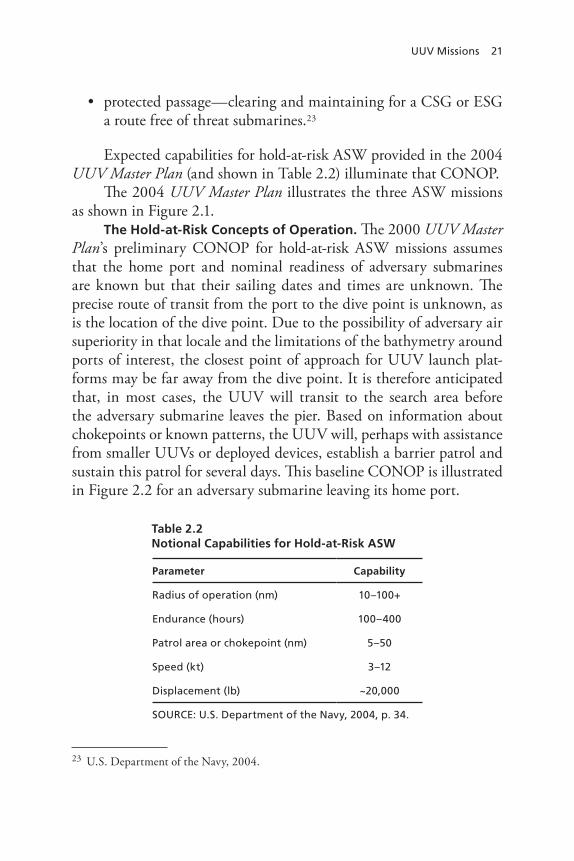
UUV Missions 21
protected passage—clearing and maintaining for a CSG or ESG •a route free of threat submarines.23
Expected capabilities for hold-at-risk ASW provided in the 2004 UUV Master Plan (and shown in Table 2.2) illuminate that CONOP.
The 2004 UUV Master Plan illustrates the three ASW missions as shown in Figure 2.1.
The Hold-at-Risk Concepts of Operation. The 2000 UUV Master Plan’s preliminary CONOP for hold-at-risk ASW missions assumes that the home port and nominal readiness of adversary submarines are known but that their sailing dates and times are unknown. The precise route of transit from the port to the dive point is unknown, as is the location of the dive point. Due to the possibility of adversary air superiority in that locale and the limitations of the bathymetry around ports of interest, the closest point of approach for UUV launch plat-forms may be far away from the dive point. It is therefore anticipated that, in most cases, the UUV will transit to the search area before the adversary submarine leaves the pier. Based on information about chokepoints or known patterns, the UUV will, perhaps with assistance from smaller UUVs or deployed devices, establish a barrier patrol and sustain this patrol for several days. This baseline CONOP is illustrated in Figure 2.2 for an adversary submarine leaving its home port.
23 U.S. Department of the Navy, 2004.
Table 2.2Notional Capabilities for Hold-at-Risk ASW
Parameter Capability
radius of operation (nm) 10–100+
endurance (hours) 100–400
patrol area or chokepoint (nm) 5–50
Speed (kt) 3–12
Displacement (lb) ~20,000
SOUrCe: U.S. Department of the navy, 2004, p. 34.

22 A Survey of Missions for Unmanned Undersea Vehicles
Figure 2.1Task Force ASW Missions
RAND MG808-2.1
SOURCE: U.S. Department of the Navy, 2004, p. 12.NOTE: A MODLOC is an assigned, fixed geographic area for unit or group operations.
Hold at risk
Hold at risk
Maritime shield
Maritime shield
Protected passage
Figure 2.2Baseline Hold-at-Risk ASW CONOP
RAND MG808-2.2
Barrier
UUV
Adversarysubmarine
Port

UUV Missions 23
During its patrol, the UUV will maneuver as necessary to classify detected targets and, upon valid detection, begin an ASW operation. During this operation, the UUV must avoid counterdetection, commu-nicate to U.S. forces that contact has been initiated, and provide periodic updates. In accordance with the sortie plan or updates issued during communication intervals, the UUV will break contact and transit to a rendezvous location. Later, perhaps after a significant loiter period, the UUV will be recovered or replenished to enable another mission.
An alternative CONOP for hold-at-risk ASW uses a number of rel-atively inexpensive, long-endurance UUVs.24 As in the earlier concepts, UUVs launch from a substantial distance and transit to the search area, most likely prior to the adversary submarine leaving the pier. Rather than establishing a barrier patrol, however, multiple UUVs maneu-ver more or less randomly in an operating area for several days. This multi-UUV hold-at-risk ASW CONOP is illustrated in Figure 2.3. The
24 Such as Slocum gliders, which are described in Appendix A. These long-endurance AUVs have been tested with towed-array sonars.
Figure 2.3Multi-UUV Hold-at-Risk ASW CONOP
RAND MG808-2.3
Adversarysubmarine
UUVs
Port

24 A Survey of Missions for Unmanned Undersea Vehicles
UUVs may not attempt to prosecute the adversary submarine; instead, multiple detections may be used to estimate the position, course, and speed of the adversary submarine. Individual UUVs will report detec-tions in near–real time.
Maritime Shield ASW Concept of Operation. Neither the 2000 nor the 2004 UUV Master Plan provides a CONOP for maritime shield ASW. The following CONOP for maritime shield ASW is based loosely on the baseline hold-at-risk CONOP described above.
The CONOP assumes that an operating area for a CSG or an ESG has been determined in advance. A host platform is positioned in advance of the strike group and begins using one or more UUVs to search the operating area for a threat submarine. Due to the possibil-ity of adversary air superiority in that locale and limited bathymetric data, a UUV launch platform may have to launch from a point outside the strike group’s operating area.25 The UUV search may be redirected in response to outside cueing information. Upon detecting a potential threat submarine, a UUV will maneuver to classify the target. Having done so, the UUV will report the target’s location and possibly begin a trailing operation to provide periodic target-location updates. Upon detecting and classifying a potential threat submarine, a UUV may be directed to relocate to a designated area. The need to avoid counter-detection might be less urgent than that presented by the hold-at-risk concept. The UUV search of the strike-group operating area then con-tinues as needed. Later, perhaps after a significant search period, UUVs will be recovered or replenished to enable another mission.
Protected-Passage ASW Concept of Operation. Neither edition of the UUV Master Plan defines a CONOP for protected-passage ASW. ONR has noted that the longest-range engagements by threat subma-rines against high-value units in passage will be conducted using wake-homing torpedoes.26 The CONOP for protected passage can therefore
25 Airdrop of UUVs is not common and serves principally as a delivery method for light-weight torpedoes. This technology would have to be adapted for this particular UUV mission. 26 Frank Herr, “DoN S&T Focus Area: Assure Access and Hold at Risk,” briefing presented at the 2007 NDIA Naval S&T Partnership Conference, August 1, 2007.

UUV Missions 25
be stated as protecting high-value units from attack for distances out to maximum torpedo-engagement range.
Observations. All suggested ASW missions for AUVs will be challenging because they require vehicles with limited sensors and pro-cessors to autonomously detect and classify threat submarines with acceptable false-alarm rates.
The maritime-shield and protected-passage concepts will also be demanding in terms of propulsion requirements. Through the applica-tion of simple models described in Appendix B, we determined that the endurance, speed, and displacement requirements associated with these concepts result in specific power and energy demands that cannot be met with current technology. A UUV meeting these criteria would need nearly three times the shaft horsepower and five times the energy density of the notional persistent ISR AUV described in Table 2.2. Achieving a five-fold increase in energy density will be problematic.
AUVs have a limited ability to communicate with the outside world. Achieving the communications requirements necessary to com-plete the kill chains that are needed to clear and maintain operating areas and routes free of threat submarines will also be problematic.
Inspection/Identification
Objectives. Inspection/identification missions support homeland defense and antiterrorism/force protection (AT/FP) needs through the inspection of ship hulls and piers for foreign objects (such as limpet mines and special attack charges). Inspection/identification also includes common activities such as underwater hull survey, ship hus-bandry, and repair.
Concept of Operation. Inspection/identification missions today are typically performed by divers. Thus, ships must be secured for diver safety before dive operations can begin. When combined with the duration of the actual diver search, the time required to assemble a search team, secure the ship, and possibly coordinate with other ships makes this mission time consuming. Poor visibility, diver disorienta-tion, tending-line entanglement, hazardous conditions (including the prospect of being crushed between a ship and a pier), and confined

26 A Survey of Missions for Unmanned Undersea Vehicles
spaces all pose risks to divers.27 Time-fused systems are also hazardous to divers.
Both AUVs and ROVs are being used successfully for this mis-sion. For both kinds of UUVs, the ship is first secured, as it is in diver operations. The UUV then systematically maps the ship hull, looking for anomalies. When UUVs are used, their sensor readings are exam-ined later. When ROVs are used, their sensor readings are available in real time.
Observation. AUVs and ROVs are used successfully today for inspection/identification in homeland security, military, and commer-cial settings. The question that remains is which conditions warrant the use of divers for inspection/identification missions.
Oceanography
Objectives. UUVs would perform oceanographic reconnaissance in near-shore, shallow-water areas while their host ships remain at a safe standoff range. UUVs could either collect oceanographic data and transmit it immediately or deliver it later. Oceanography missions for UUV operations include
bottom mapping•bathymetry•acoustic imaging•optical imaging•subbottom profiling• 28
water-column characterization, including•ocean-current profiles (with tides) –temperature profiles –
27 Scott Stuart, “Enabling Access: Acquisition Perspective,” PMS-EOD briefing to the Mine Warfare Association Meeting, May 2005.28 Subbottom-profiling systems are used to identify and characterize layers of sediment or rock under the sea floor. The technique used is similar to that employed by a simple echo sounder: A transducer emits a sound pulse vertically downward toward the sea floor, and a receiver records the return of the pulse once it has been reflected off the sea floor. Parts of the sound pulse penetrate the sea floor and reflect off the different subbottom layers, providing information on these subfloor sediment layers.

UUV Missions 27
salinity profiles –water clarity –bioluminescence. –
Oceanography and MCM missions overlap. The use of UUVs to gather oceanographic data in near–real time to improve the effective-ness of MCM operations by other platforms has been demonstrated.29
Concepts of Operation. Two distinct CONOPs emerge. One is a CONOP for gathering environmental data that are not time sensitive. Bottom mapping, subbottom profiling, and ocean-current profiling are examples of these operations, which could be conducted in peacetime from a variety of platforms. The second CONOP is for collecting data that are more time sensitive.
Observations. The collection of time-sensitive oceanographic data occurred, for example, during Exercise SHAREM 150, which saw the use of UUVs to collect oceanographic information. In this 2005 exercise, four glider AUVs30 were deployed for 22 days in an opera-tional area in the Sargasso Sea, and a fifth UUV was held in reserve. A simple AUV control center was established using a laptop computer and a modem bank. The four AUVs provided 4,872 real-time measure-ments of salinity, temperature, and depth during the exercise, while standard platforms provided just 367 Expendable-Bathythermograph31 traces and 19 measurements of salinity, temperature, and depth. At the request of naval platforms participating in the exercise, the UUV deployment was extended for the duration of the full exercise. Although one UUV encountered an overpowering eddy, none of the UUVs failed during the exercise.32
29 This topic is addressed in Chapter Three.30 Gliders are described in Appendix A.31 An Expendable Bathythermograph is a probe that is dropped from a ship to measure the sea temperature as the probe falls through the water. Two fine wires transmit temperature data to the ship where they are recorded for later analysis. The probe falls at a known rate, so the depth of the probe can be inferred from the time elapsed since the drop.32 Clayton Jones, Slocum Gliders—A Component of Operational Oceanography, Webb Research Corporation and Rutgers University, undated.
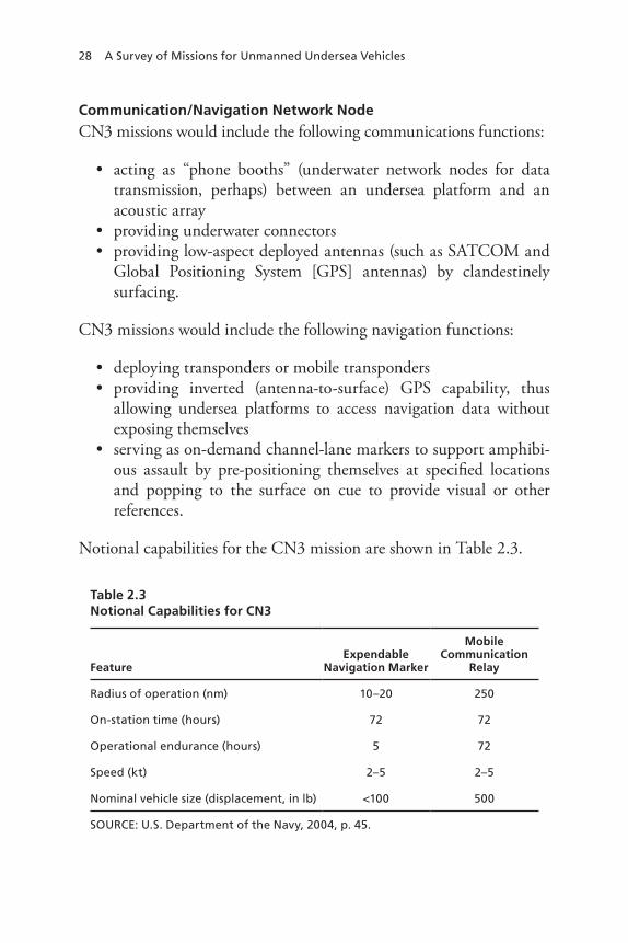
28 A Survey of Missions for Unmanned Undersea Vehicles
Communication/Navigation Network Node
CN3 missions would include the following communications functions:
acting as “phone booths” (underwater network nodes for data •transmission, perhaps) between an undersea platform and an acoustic arrayproviding underwater connectors•providing low-aspect deployed antennas (such as SATCOM and •Global Positioning System [GPS] antennas) by clandestinely surfacing.
CN3 missions would include the following navigation functions:
deploying transponders or mobile transponders•providing inverted (antenna-to-surface) GPS capability, thus •allowing undersea platforms to access navigation data without exposing themselvesserving as on-demand channel-lane markers to support amphibi-•ous assault by pre-positioning themselves at specified locations and popping to the surface on cue to provide visual or other references.
Notional capabilities for the CN3 mission are shown in Table 2.3.
Table 2.3Notional Capabilities for CN3
FeatureExpendable
Navigation Marker
Mobile Communication
Relay
radius of operation (nm) 10–20 250
On-station time (hours) 72 72
Operational endurance (hours) 5 72
Speed (kt) 2–5 2–5
nominal vehicle size (displacement, in lb) <100 500
SOUrCe: U.S. Department of the navy, 2004, p. 45.

UUV Missions 29
The stated objective of CN3 functions would be to provide on-the-spot connectivity and navigation capability for a variety of plat-forms conducting ASW, MCM, and SOF missions.33 In particu-lar, network nodes would provide the following for SOF operations (including dive missions): (1) radio-frequency line-of-sight and satel-lite communication and (2) acoustic communication with small UUVs and submarines operating at depth and speed. They would also support SOF/EOD forces ashore or in the water and enable data retrieval and exchange with undersea systems.34
With regard to navigation functions, the 2004 UUV Master Plan states that,
as a navigation aid, the CN3 UUV is envisioned as an on-site on-demand reference point for subsea or surface operations. Pre- positioned, either just prior to, or well in advance of planned operations, the vehicles will provide reference beacons (visual, radar, or acoustic) for other UUVs, submarines, SOF, or surface operations. These could take the form of lane designators, under-sea mileposts, or supplementing or replacing conventional naviga-tion means. In critical situations, the CN3 UUV could provide an above- or below-water navigation capability equivalent to GPS accuracy without the need for continuous direct satellite commu-nications. CN3 UUVs will also aid less-capable UUV systems, providing a mobile geographic reference system. An immediate mission would be a self-deploying navigation transponder for use by SOF vehicle systems.35
Concept of Operation. Communications and navigation mis-sions require predeployment of network nodes, underwater connec-tors, and vehicles. The notional capabilities for CN3 vehicles (shown in Table 2.3) indicate that predeployment needs to occur within days of such vehicles’ use. A CN3 UUV would be deployed at a safe distance from its objective, transit to the operations area, and then deploy itself
33 U.S. Department of the Navy, 2004, p. 44.34 U.S. Department of the Navy, 2004, p. 43.35 U.S. Department of the Navy, 2004, p. 43.

30 A Survey of Missions for Unmanned Undersea Vehicles
as a communications or navigation asset. Given their small size, CN3 UUVs would be deployed from surface vessels; they are too small to be launched from a torpedo tube.36
Observations. The use of UUVs for CN3 requires extensive mast exposure, which would compromise such vehicles’ covertness. This mission also requires considerable electrical power for transmissions. SSVs might be more appropriate than UUVs for some CN3 missions.
Payload Delivery
Objectives. The payload-delivery mission operates from the prem-ise that large UUVs can facilitate logistics by providing clandestine supply and support without exposing high-value platforms. Potential payloads include
supplies pre-positioned for SOF or EOD missions•cargo that follows Sea-Air-Land (SEAL) Delivery Vehicles •(SDVs)sensors or vehicles deployed in support of ISR, ASW, mine war-•fare (MIW), oceanography, CN3, or TCSMCM neutralization devices•weapons for deployment or pre-positioning.•
Concepts of Operation. CONOPs for payload delivery vary according to the particular mission being supported. The UUVs involved will require a high degree of autonomy, good navigation capa-bilities, and a large energy store. Such vehicles will be relatively large and require a corresponding propulsion system.37 UUV recovery fol-lowing mission completion will be expected.
CONOPs are provided by the 2004 UUV Master Plan for the fol-lowing areas:
36 U.S. Department of the Navy, 2004, p. 43.37 U.S. Department of the Navy, 2004, pp. 47–48. The estimated weight of the UUV is 10 tons.

UUV Missions 31
Supplies pre-positioned for SOF or eOD missions.• Supplies for SOF or EOD forces are pre-positioned when those forces cannot themselves transport those supplies. Supplies pre-positioned to support SOF could include weapons, food, batteries, and fuel. For example, SOF who parachute into an objective area might not be able to carry their own food supplies and means of exfiltration. Supplies could therefore be pre-positioned at a predetermined location in a manner that both prevents their deliberate discovery (e.g., by organized enemy patrols) or incidental discovery (e.g., by fishermen) and ensures that the SOF personnel can quickly and reliably locate and use them. This mission places a premium on the reliability and dependability of the UUVs involved. In fact, the SOF team’s survival could depend critically on UUV per-formance, and there could be no chance of hardware failure or accidents (such as a UUV becoming entangled in a fishing net). A UUV would have to communicate its success in pre-positioning supplies and perhaps transmit information regarding their loca-tion. Supplies pre-positioned for EOD forces could include mine-neutralization devices.Cargo that follows SDVs.• Two CONOPs for using UUVs to deliver cargo that follows SDVs are apparent. The first concept strongly resembles the pre-positioning concept except that cargo is emplaced after an operation has begun rather than before it. This concept places even greater demands on the reliability and dependability of UUVs than those associated with pre-position-ing. This is because the pre-positioning CONOP offers the oppor-tunity to replace a failed UUV, whereas the follow-on concept does not. A second follow-on UUV concept involves a UUV that follows closely behind an SDV. This concept removes some of the requirements for autonomy and navigation.Sensors or vehicles deployed in support of ISr, ASw, MIw, •oceanography, Cn3, or TCS. The 2004 UUV Master Plan illustrates this CONOP for oceanography. In this CONOP, a large UUV supporting oceanographic operations transports and deploys drifting or fixed objects to support oceanographic sur-veys. These objects may be drifting buoys, which could be dis-

32 A Survey of Missions for Unmanned Undersea Vehicles
persed over a region to accelerate the collection of oceanographic data. Bottom-mounted sensors may also be deployed in support of long-term oceanographic-data collection. Alternatively, a large UUV may deploy mobile devices, such as oceanographic glid-ers. Upon completion of their missions, these oceanographic gliders may autonomously move to a collection point to be retrieved and prepared for reuse. Concepts for CN3 and TCS are discussed elsewhere in this book.MCM-neutralization devices.• To support an MCM mission, a large UUV would provide the capability to insert smaller devices into forward areas. Its sensors could detect mine-laying opera-tions, a swarm of smaller vehicles that perform mine reconnais-sance, mine-neutralization devices, or mine-neutralizing UUVs. As previously noted, the 2004 UUV Master Plan envisages MCM operations in regions varying in size from 100 nm2 to 900 nm2 and spanning the water column, ranging from deep mineable waters to the beach. Such operations should be completed in 7–10 days or less.weapons for deployment or pre-positioning• . This mission is discussed in the first bullet of this list.38
Information Operations
Objectives. The study group for the 2004 UUV Master Plan iden-tified two information operations (IO) roles for UUVs:
Jam or inject false data into enemy communications or computer •networks, or conduct denial-of-service operations to degrade net-works unreachable by other platforms.Act as submarine decoys in wartime with the objective of imped-•ing enemy maritime operations by increasing fear of attack by a nonexistent or minimal U.S. submarine threat. Alternatively, UUVs could enhance the safety of friendly submarines by causing adversaries to dilute their ASW efforts. They could also cause ene-
38 U.S. Department of the Navy, 2004, p. 48.
UUV Missions 33
mies to alter their plans (e.g., enemies could decide not to operate in an area thought to be dangerous).39
Concepts of Operation. CONOPs for jamming, injecting false data, or conducting denial-of-service operations differ from those asso-ciated with acting as a submarine decoy. In the former set of roles, UUVs could conduct electronic attacks in littorals, using their small size and stealth to operate in areas unreachable by other platforms to gain proximity to susceptible communications nodes. Injection of false data is recognized to be difficult, as it requires a reliable communica-tions link with the vehicle or a sophisticated degree of autonomy that permits the vehicle to recognize and act on the opportunity to inject the erroneous data.40
As submarine decoys, UUVs could transit an area known to contain enemy ASW forces or sensors using a preprogrammed path designed to attract attention and provoke an enemy response. Sophisticated UUVs could react to prosecution, become evasive, and perhaps even manipu-late their own acoustic signatures to mimic manned submarines. If they escape prosecution, they could repeat their decoy actions.41
Time-Critical Strike
Objectives. TCS provides the ability to deliver ordnance to a target with sensor-to-shooter closure time measured in seconds rather than minutes. It also moves the “flaming datum” away from high-value platforms and thus reduces the platforms’ vulnerability.42
Concepts of Operation. TCS operations involving UUVs would occur across platforms, vehicles, and weapons in the battlespace. The launch of weapons from a UUV or from a UUV-delivered weapon cache would allow a launch point to be closer to the target, thus result-
39 U.S. Department of the Navy, 2004, p. 50. An additional objective of the use of decoy submarines is to stimulate the ASW defenses of a potential adversary in order to gain insights into capabilities and tactics, command-and-control procedures, sensor-field locations, etc.40 U.S. Department of the Navy, 2004, p. 49.41 U.S. Department of the Navy, 2004, p. 50.42 U.S. Department of the Navy, 2004, p. 50.

34 A Survey of Missions for Unmanned Undersea Vehicles
ing in a quicker response time for prosecution.43 A ballistic weapon would be required to achieve the stated goal of achieving sensor-to-shooter time in seconds. The weapon would be encapsulated in a UUV or in a cache system.
The 2004 UUV Master Plan suggests three CONOPs for UUVs in TCS:
Launch from bottomed UUVs.• In this CONOP, UUVs are launched so that they “bottom” (i.e., rest upon the ocean’s floor) in a launch basket.44 Once bottomed, UUVs report their status periodically to assure reliable launch. Following determination that a given UUV should launch against a target, a launch com-mand is transmitted to that UUV.Launch from loitering UUVs.• A second alternative is to launch a weapon from a UUV that is loitering in the water column of the launch basket. This CONOP differs from the bottomed-UUV CONOP in that loitering UUVs may be required to periodi-cally rendezvous with a dedicated host platform to replenish their energy and redeploy.Launch from weapon caches.• In this alternative, a UUV trans-porting a weapon cache is launched so that the cache (but not the UUV) bottoms in a suitable location. The UUV returns to the host platform and is prepared to launch another cache.45 Once deployed, weapon caches report their status periodically to assure reliable launch. Following determination that a given weapon cache should launch against a target, a launch command is trans-mitted to that cache.46
43 U.S. Department of the Navy, 2004, p. 50.44 In some cases, this launch basket could prove to be located in an area that the United States believes is likely to be denied during an anticipated conflict. In these circumstances, UUVs could be launched in advance of the conflict.45 As in the case of bottomed UUVs, the launch area could prove to be an area that the United States believes is likely to be denied during an anticipated conflict. In these circum-stances, UUVs could be launched and caches deployed in advance of the conflict.46 U.S. Department of the Navy, 2004.

UUV Missions 35
Other Missions for UUVs
Undersea Test Platform
Objectives. The large-scale vehicles (LSVs) Kokanee (LSV-1) and Cutthroat (LSV-2) are operated by Naval Sea Systems Command, Acoustic Research Detachment (NAVSEA 073R), as unmanned, autonomous submarine test vehicles. These LSVs are used to measure radiated noise, test propulsion designs, validate predicted maneuver-ing and flow-management characteristics, and test design modifica-tions (such as new sail designs). Kokanee is a quarter-scale model of the USS Seawolf (SSN-21), and Cutthroat is a 0.294-scale model of the USS Virginia (SSN-774). Cutthroat is 111 ft (33.83 m) long, has a 10-ft (3.05-m) beam, and is equipped with a 3,000–shaft hp electric motor. It is the world’s largest AUV and is half the size of early World War II submarines.47 Newport News Shipbuilding was awarded a $46,868,246 cost-plus-incentive-fee contract in 1999 to complete the design and construction of the Cutthroat.48
Concept of Operation. Submarine test vehicles, such as LSVs, are designed to be large enough that they faithfully reproduce the hydro-dynamic and acoustic properties of actual submarines and can accom-modate the installation of nonintrusive critical instrumentation but small enough to minimize the costs of design testing and demonstra-tion. For example, both Kokanee and Cutthroat are operated in Lake Pend Oreille in Bayview, Ida., which provides a deep (1,150-ft), quiet body of water with a free-field, ocean-like environment that does not entail the problems and costs of open-ocean operations.
Dr. Michael Pierzga, head of the fluid hydrodynamics division at the Applied Research Laboratory, Pennsylvania State University (ARL Penn State), has observed that the decision to make LSVs at least one-quarter the size of new-design submarines was made in the 1980s. That determination was based on the state of the art for hydrodynamics
47 S-class submarines, used early in World War II, were 219 ft, 3 inches long with a beam length of 20 ft, 6 inches.48 GlobalSecurity.org, “Large Scale Vehicle LSV,” Web page, undated, last updated April 27, 2005.

36 A Survey of Missions for Unmanned Undersea Vehicles
at the time. Dr. Pierzga has further observed that the current state of the art for hydrodynamics now supports the creation of eighth-scale vehicles.49 At one-eighth scale, a test vehicle for the USS Virginia would be 47 ft long and have a 51-inch beam. This is only slightly bigger than the large AUV with a 48-inch beam now under construction at ARL Penn State. A submarine-design test vehicle could be developed by encasing a large AUV (like the one being developed at ARL Penn State) in a hydrodynamic skin. Such a vehicle could be constructed more quickly and cheaply than an LSV, thus allowing for experimenta-tion over a wider range of designs. Dr. Pierzga has also stated that the relatively high cost of LSVs tends to limit maneuvering-test conditions. With a less costly, more readily replaced vehicle, vehicle testing could be conducted over a wider range of maneuvers.
Drew Meyer, the large-model manager at NAVSEA 073R, has confirmed that vehicles such as those proposed by Dr. Pierzga would be suitable for maneuverability tests similar to those conducted using sixteenth-scale models. Larger, quarter-scale models (and, potentially, eighth-scale models) can be used to gain a higher level of confidence in predicting the performance of new designs. Propulsor acoustic and hydroacoustic testing, however, must be conducted at approximately LSV (i.e., one-quarter) scale or larger to achieve accurate results.50
In-Stride Minefield Transits
Objectives. In-stride minefield penetration would enable ships to safely transit suspected minefields without advanced preparation or outside assistance and without stopping or turning back in the mine-field. The creation of a route through the minefield that is usable by other ships is a secondary objective that requires determining the abso-lute location of the route through precision navigation.
Concept of Operation. The capability for in-stride minefield tran-sits would be provided organically. As a ship nears a suspected mine-field, it would deploy a UUV that would operate in advance of the ship, sensing mines and communicating mine locations to the ship in
49 Author interview with Dr. Michael Pierzga, State College, Penn., December 2007.50 Author interview with Dr. Michael Pierzga, State College, Penn., December 2007.

UUV Missions 37
near–real time. In the event that mines are unavoidable, the UUV will neutralize those mines to create a route. Mine neutralization would be accomplished reliably without risk to the UUV.51
Submarine Search and Rescue
Objectives. ROVs have been used in search-and-rescue (SAR) missions to recover bodies, evidence, and flight-data recorders. ROVs can be used during searches to inspect potentially dangerous locations ahead of dive operations. ROVs may also be attractive for SAR opera-tions in certain environmental conditions, such as under ice on frozen lakes or in highly polluted water. A tow fish used to survey an area of interest may be followed by ROV operations to inspect objects detected by the tow fish.
Concept of Operation. SSAR operations that have been conducted successfully (described below) illustrate the SAR CONOP. Note that our focus here is on SSAR.
ROVs can allow rapid, self-contained deployments of support personnel, supplies, and equipment using commercial or military air-lift to vessels of opportunity. While manned systems are deploying, ROVs can inspect a downed submarine, emplace on it communication and acoustic navigation devices, and provide emergency oxygen to the submarine crew.
The first successful submarine rescue using an ROV occurred in 1973, when the Cable-Controlled Underwater Recovery Vehicle was used to rescue the two-man submersible Pisces III from the bottom of the ocean off Ireland. Subsequently, the United Kingdom implemented an SSAR system using a Scorpio ROV (described in a later section) and the LR5 manned submersible, a small deep submergence rescue vehi-
51 In Chapter Four, this operational concept is described more expansively for the Saab Double Eagle UUV, which can operate as an ROV or as an AUV. In transiting a minefield, the Double Eagle would operate as an ROV ahead of the host vessel, passing sensor data back to the hose via its tether. Powering the Double Eagle remotely would enable it to operate indefinitely at speed ahead of the host vessel. Destructive charges could be dropped by the Double Eagle to neutralize mines without risk to the vehicle itself.
38 A Survey of Missions for Unmanned Undersea Vehicles
cle (DSRV).52 The SSAR concept was demonstrated in August 2005, when a fishing net trapped the Russian DSRV Priz with a crew of seven at a depth of 620 ft on the sea floor off the Kamchatka Peninsula. Both free escape by the crew and diver rescue were unfeasible at this depth. The UK’s SSAR ROV and its team were flown by C-17 to the region and transported by Russian surface ships to the scene. The ROV freed the trapped rescue vehicle, allowing it to surface and saving all seven crew members. The same SSAR ROV was also used in an earlier but unsuccessful attempt to rescue the crew of the Russian submarine Kursk. Australia, Japan, and Sweden are developing similar capabilities for SSAR. Russia is now developing an ROV-based SSAR capability in which a specially fitted ROV cuts away debris and injects air into a submarine in distress.
ASW Training
ASW training targets are now being used to simulate submarines as ASW targets in open-ocean and instrumented range exercises. AUVs have been used for over a decade as ASW training targets. Today, two types of training targets are used by the Navy: the reusable MK-30 Acoustic Target and the MK-39 Expendable Mobile ASW Training Target (EMATT). Training features offered by ASW training tar-gets are illustrated in Chapter Five, where we also describe the most-advanced ASW training target (the MK-39 Mod 2 EMATT).
Objectives. The objective of ASW training with UUVs is to develop and assess team and unit tactical proficiency in the detection, classification, localization, tracking, or attack of submarines at sea. ASW training using UUVs supports team and unit training evolu-tions and complements and augments simulation-based ASW training (which is expected to cost less than at-sea training).
Concepts of Operation. The current CONOP for ASW train-ing using UUVs is our starting point for future CONOPs. In this CONOP, the unit receiving the training deploys to an ASW train-
52 The LR5 is approximately 9 ft long and 10 ft wide; it can operate at a depth of 1,500 ft. The entire LR5 system can be transported in two C-17 loads or one C-17 load supplemented by six C-130 loads.
UUV Missions 39
ing range. Training begins with the launch of a UUV by a second platform (i.e., a surface combatant, a maritime patrol aircraft, or an ASW helicopter) and ends several hours later when the UUV’s energy is expended. An alternative CONOP involves the use a UUV whose endurance is measured in weeks or months (see Chapter Four). Such a UUV could offer the advantage of eliminating the need for a second platform (i.e., a surface combatant or an aircraft) to launch the UUV. It could also allow for longer training evolutions (possibly across mul-tiple watches).
Going one step further, a long-endurance UUV for ASW training could be used in situ by a deployed vessel. The deployed vessel (e.g., an LCS) could launch the training UUV some time after reaching its operating area, then periodically conduct in situ ASW training with that UUV. At the end of a training evolution, the UUV’s recorded track data could be downloaded on the deployed vessel via UUV recov-ery or radio-frequency transmission. Enhanced environmental under-standing could be gained by relating ASW performance to the UUV’s recorded track data, which would be interpreted as ground truth. Given months of UUV endurance, there might be little need to recover the UUV immediately after completing a training evolution. The deployed vessel would simply be expected to recover the UUV at the end of its deployment.
Support for Special Operations
This book’s objectives and CONOPs for using UUVs in support of SOF were developed through discussions with SEAL Delivery Teams 1 and 3 and Naval Special Warfare Command.
Objectives. UUVs currently support SOF operations through battlespace preparation. For example, the Semi-Autonomous Hydro-graphic Reconnaissance Vehicle (SAHRV) performs bottom surveys in advance of SOF operations and maps regions of interest for mine-like objects. In this example, SAHRV is being used in place of operators. The feasibility of using an AUV to provide ISR in support of over-the-beach operations was demonstrated during Exercise Giant Shadow in 2003. In this instance, in providing ISR support for over-the-beach operations to enhance the effectiveness of and reduce the threat to SOF

40 A Survey of Missions for Unmanned Undersea Vehicles
personnel, an AUV acts as an adjunct to operators. The objectives of using UUVs in special operations would be to improve capabilities, provide capabilities with less risk, or to create new capabilities for SOF operations.
Concepts of Operation. The 2004 UUV Master Plan outlines two broad CONOPs for UUVs in special operations: (1) the deployment of leave-behind sensors or sensor arrays and (2) resupply (either directly following a SEAL team as it infiltrates an area or providing supplies and equipment as an operation progresses). Tactical ISR support in over-the-beach operations was outlined above. A number of other missions for UUVs in special operations have been suggested, including using AUVs to (1) tag enemy vessels (to make them easier to detect, classify, and track), (2) assist in planning SOF infiltration routes,53 (3) provide bioluminescence management for SEAL operations, and (4) support various forms of direct action. Most of these missions would use AUVs; some would use ROVs.
Monitoring Undersea Infrastructure
Objectives. The U.S. military depends on an extensive undersea infrastructure that includes undersea communication cables, instru-mented ranges, and the Integrated Undersea Surveillance System (IUSS). The Department of the Navy has stated that
the Fixed Surveillance System (FSS) program is a major portion of the Integrated Undersea Surveillance System (IUSS). FSS con-sists of fixed deep water arrays connected to shore processing sites, called Naval Ocean Processing Facilities, by over 30,000 nautical miles of undersea cable. The system supports Fleet Commands and tactical forces by detecting, tracking, and reporting informa-tion on submarines, surface ships and aircraft over the oceans. In addition to this primary mission the system is also used for other surveillance and research efforts such as: long term oceanographic
53 Assistance in planning SOF infiltration routes might have the objective of enabling SEAL teams to infiltrate more quickly and thus spend more time ashore during a single cycle of darkness. Another objective might be to reduce threats to SEAL teams during infiltration and exfiltration.

UUV Missions 41
studies, undersea geological observation, mammal research, fish-ery regulation, environmental research and drug interdiction.54
To various degrees, different components of the undersea infra-structure are vulnerable to the inevitable effects of aging and to marine life, anchors and fishing nets, and malfeasance. The objectives of this mission are therefore to inspect undersea systems to detect damage to them and ensure that they have not been subjected to tampering.
Concept of Operation. Visual inspection of critical components of the undersea infrastructure, or areas where its components are buried, is required to detect damage and possible tampering. Video equipment, with supporting light sources, would be used to image portions of the system or regions where such components are buried. Additionally, sensors (such as magnetometers) would be used to track buried cables.
Commercial Missions
The following missions are clearly not military missions. They are pre-sented to illustrate UUV capabilities in nonmilitary missions that share features with advocated military missions. This section also describes the types of commercial UUVs selected to perform these missions.
Offshore Oil and Gas Missions
Most commercial missions for UUVs occur in the offshore oil and gas industry. Their value for offshore surveys has been demonstrated through their accurate and efficient surveys in the deep waters of the Gulf of Mexico and west of Africa. Their value in shallow water has not yet been demonstrated. Ten AUVs are now in use for offshore oil and gas surveys (see Table 2.4). The HUGIN 3000 (with five units fielded) has become the de facto industry standard.55
54 U.S. Department of the Navy, Fiscal Year (FY) 2002 Budget Estimates Submitted to Con-gress: Justification of Estimates, Operation & Maintenance, Budget Activity 2, June 2001b, p. 84.55 Jane’s Information Group, Ltd., “Executive Overview: Underwater Warfare,” Web page, 2008.

42 A Su
rvey of M
ission
s for U
nm
ann
ed U
nd
ersea Veh
icles
Table 2.4AUVs Operated by the Offshore Oil and Gas Industry
Vehicle Manufacturer OperatorYear Entered
Service
hUGIn 3000 Kongsberg Maritime C&C technologies 1999
Maridan 200 Maridan (now Atlas elecktronik) De Beers pty 2001
echo ranger Boeing Fugro/Oceaneering 2003
hUGIn 3000 Kongsberg Maritime AS Geoconsult 2003
hUGIn 3000 Kongsberg Maritime Fugro nV 2004
Geosub Subsea 7/nOC, Southampton Subsea 7 2004
hUGIn 3000 Kongsberg Maritime C&C technologies 2004
hUGIn 4500 Kongsberg Maritime C&C technologies 2006
hUGIn 3000 Kongsberg Maritime Fugro nV 2006
Bluefin-21 (echo Mapper) Bluefin robotics Fugro nV 2006

UUV Missions 43
With a relatively small number of vehicles apparently saturating the market for deep-sea surveys and preventing further sales, these AUVs may have become the victims of their own success. Kongsberg Maritime, joined by C&C Technologies and General Atomics, is trying to expand the market for HUGIN AUVs by advocating their military missions.
The following commercial missions for UUVs have been identi-fied for this book as having clear links to military missions. An under-standing of these missions gives insight into UUVs’ abilities to conduct military missions.
Undersea-Cable Deployment and Inspection
AUVs have been used commercially for over a decade to deploy and inspect undersea cables. AUVs have been used on continental shelves and under the Arctic icecap to deploy cable systems. Significant cost savings in selecting routes for undersea cables have been realized by using AUVs to map the bottom. AUVs are also advantageous in rela-tively deep water where deployment from surface ships could require excessive lengths of cable in the water (creating excessive cable tension). They are also used in water too shallow for cable-laying ships.
Nuclear-Industry Inspections
Small “eyeball” ROVs, which are ROVs equipped primarily with opti-cal sensors, are used inside nuclear-power plants to conduct inspection, intervention, and decommissioning tasks. In 2006, China reported development of a low-cost ROV for use inside nuclear reactors. This ROV is designed to pick up small objects weighing less than 1 kg.
Commercial Salvage
ROVs are used today to conduct initial surveys of wrecks and their car-goes, to place explosive charges for breaching hulls, to inspect the work of grab systems used to bring cargo to the surface, to clear obstacles and potential snag points, and for light retrieval.

44 A Survey of Missions for Unmanned Undersea Vehicles
Aquaculture
ROVs are used to patrol fish pens for intruders and breaks in netting and to retrieve dead fish. This is more efficient and less dangerous than using divers for fish-pen inspections. The tasks required for these mis-sions are clearly related to hull- and harbor-security missions.
Science Missions
The following science missions for UUVs have been identified for this book as having clear links to military missions. Again, an understand-ing of these missions gives insight into UUVs’ abilities to conduct mili-tary missions.
Oceanographic Observing Systems
Oceanographic observing systems generally involve the installation of seabed junction boxes that provide power and data-transmission infra-structure to suites of oceanographic instruments and sensors and con-nect the observatory area to users ashore via fiber-optic cables. Power and data nodes must be positioned accurately. Science ROVs have dem-onstrated the ability to place nodes with an accuracy of a few meters.
Marine Archeology
Marine archaeology studies human interaction with the sea, lakes, and rivers through the study of vessels, shore-side facilities, cargoes, human remains, and submerged landscapes. Marine archeology includes underwater archeology, which studies the past through examination of submerged remains, and nautical archaeology, which studies vessel construction and use. Marine archeology was brought to the public eye in 1985 with the discovery and exploration of the wreck of the RMS Titanic, which lies on the bottom under 13,000 ft of water. The ROV Jason mapped and explored this wreck and retrieved artifacts from the site. The detection, identification, mapping, and retrieval of artifacts clearly relates to military missions for UUVs.

45
ChApter three
UUV Subsystems and Technologies
Background
The general description of UUV systems and technologies provided in this chapter is needed to understand selected UUVs described in the next chapter.1 This material is also needed to characterize risk and maturity. Technologies that can be approached as engineering exercises or for which adequate commercial solutions exist are considered to be mature. Immature technologies require research and development. For example, although electric-motor technology continues to be refined, commercially available electric motors are adequate for most UUV applications. Electric motors are therefore considered to be a mature technology. Conversely, artificial intelligence for UUVs is currently a problem that requires additional active research and development for certain military UUV missions. Therefore, it is deemed immature. UUV missions that depend on immature technologies are considered to be at technical risk. However, some immature technologies are not associated with technical risk for missions because no UUV mission depends on those technologies.
This chapter concludes with a discussion of UUV reliability that compares the potential reliability of UUVs to the reliability of alterna-tive manned vehicles.
1 Note that a comprehensive treatment of UUV technologies is far beyond the scope of this limited study. We have constrained our discussion to technologies relevant to this study.

46 A Survey of Missions for Unmanned Undersea Vehicles
UUV Subsystems
The major UUV subsystems for AUVs are
the pressure hull•the hydrodynamic hull•ballasting•power and energy•electrical-power distribution•propulsion•navigation and positioning•obstacle avoidance•masts•maneuver control•communications•locator and emergency equipment•payloads.•
This list of subsystems—minus the hydrodynamic hull and power and energy items—also applies to ROVs with traditional power tethers. Power tethers limit movement but provide virtually limitless energy, thereby making hydrodynamics less relevant for ROVs.2 Note that gliders are equipped with buoyancy-management systems.
ROVs generally have fewer subsystems than AUVs. They often lack navigation and radio or acoustic communication systems. ROVs use imaging systems, including external lighting, as primary sensors and typically use a manned control station for mission execution.
Pressure Hulls
Pressure hulls enable UUVs to withstand sea pressure as they descend into the ocean. The pressure to which a UUV is subjected increases linearly with depth. Roughly speaking, each 10 m (32.8 ft) of depth increases pressure by 1 atmosphere (14.7 psi). Thus, at 300 m (984 ft), sea pressure is about 441 psi. At 6,000 m (19,685 ft), sea pressure is
2 Instead, ROVs may need specialized designs for station-keeping and precision positioning.

UUV Subsystems and technologies 47
about 4.4 tons per square inch. However, small hulls (such as AUV hulls) are better able to withstand pressure than are large hulls (such as submarine hulls). Hence, the hulls of AUVs intended for relatively shallow operation can be fabricated from easily worked materials, such as aluminum. Therefore, cost and volumetric efficiency are the primary considerations. In fact, engineering software to facilitate such trade-offs is commercially available. Pressure-hull technology for AUVs is mature.
Hydrodynamic Hulls
Hydrodynamic hulls reduce drag as UUVs move through the ocean. The trade-offs associated with hydrodynamic drag are more complex than those associated with pressure. Reducing drag to maximize speed and endurance is one design objective. Another is controlling flow over the exterior of the UUV body for efficient propulsion. At low speeds (around 2 kt), stability and maneuverability are problematic. At higher speeds, stability for sensor operation becomes an issue. In AUV design, speed and endurance are generally traded for stability.
Although the energy available to ROVs is practically unlimited, their usable power is limited by umbilical-cable and propulsor designs. Vehicle propulsion must overcome both vehicle and umbilical-cable drag. Umbilical cables are designed with the knowledge that increas-ing cable thickness (i.e., amperage) increases cable drag, which can be self-defeating. Reduced hydrodynamic drag for the ROV body thus enables higher speed (especially at depth, where umbilical cables have the greatest cross-sectional area) and enables ROVs to work with greater umbilical-cable lengths. Higher speed enables ROVs to perform certain missions, such as searching and mapping, more quickly. Higher speed also allows ROVs to hold their position against stronger currents. The VideoRay ROV, described in Appendix A, is capable of 4.1 kt, which compares favorably to the speed of many AUVs. Greater umbilical-cable lengths enable ROVs to operate at greater distances from host platforms, making them more competitive with AUVs in operational standoff distances.
Computer software for hydrodynamic calculations is avail-able. Moreover, the relatively small size of UUVs can make full-scale

48 A Survey of Missions for Unmanned Undersea Vehicles
hydrodynamic testing possible. Hydrodynamics for UUVs is a mature technology.
Ballast Systems
Ballasting enables AUVs to operate at neutral or near-neutral buoy-ancy such that the hull is nearly horizontal when submerged. Fixed- buoyancy systems that use lead or foam are engineered into the AUV and adjusted as changes to vehicle components or payloads occur. Onboard variable-ballast systems are often required to aid ascent or descent or compensate for payload deployment.3 Emergency drop weights, also part of ballast systems, are released in the event of hard-ware failure so that the vehicle returns to the surface. The design of ballast systems is considered routine engineering, and ballast-system technologies are mature.
Power and Energy Systems
Loosely speaking, the power available to a UUV determines how fast it can go, while energy determines how far it can go. When their power is provided by tether systems, energy is not an issue for ROVs. Energy is of minor concern to gliders, whose extraordinary energy efficiency makes using commercial alkaline batteries as an energy source practi-cal. Such batteries are readily available, reliable, and inexpensive. One new glider design now being tested harvests energy from temperature differences in the ocean and has operated continuously for over a year. Solar-powered AUVs that recharge periodically on the surface have also been demonstrated.
With ever-growing demand for vehicle speed and endurance and additional sensors and onboard processing, energy is an issue for tradi-tional AUVs. Lead-acid batteries became common AUV power sources in the 1980s. However, such batteries are dense (which works against vehicle designs that aim for approximately neutral buoyancy) and provide relatively little energy given their weight. Silver-zinc batteries replaced lead-acid batteries but proved expensive and vulnerable to fail-
3 Gliders bank and turn with minimal energy expenditure by shifting internal weights from side to side.

UUV Subsystems and technologies 49
ure after relatively few cycles. More recently, vehicles have used lithium primary batteries, which are not rechargeable. Nickel metal hydride (NiMH) batteries have been used as rechargeable power sources, and NiMH development is ongoing. Commercial alkaline batteries are sometimes used in large numbers to power traditional, torpedo-like AUVs. Development of aluminum/oxygen “semi-cell” power sources began in 1987, and such sources have since entered service. Lithium ion batteries are in common use today; their pressure-tolerant designs enable rapid battery exchanges. Conventional fuel cells have also been fielded successfully and offer significant advantages in power density compared to lithium ion batteries. British Aerospace (BAE) recently demonstrated an AUV that can recharge itself on the surface using a small diesel engine. ARL Penn State has been developing an engine that burns powdered aluminum using saltwater as the oxidizer.
Despite roughly order-of-magnitude increases in power and energy offered by new technologies, power and energy are still an issue for tor-pedo-like AUVs. A survey of AUV developers conducted in the spring of 2008 by AUVSI and RAND indicates that propulsion power and energy are the second-greatest long-term challenge to AUV develop-ment (after autonomy). Given the level of ongoing research and devel-opment of power and energy systems and the AUVSI/RAND survey, power and energy technologies for traditional, torpedo-like AUVs are deemed immature.
New technology is allowing glider power and energy (used for propulsion and to operate vehicle systems) to be harvested from the sea using temperature differences in the ocean. Gliders using this technol-ogy may be able to operate continuously for a year or more without being refueled or recharged. However, even existing glider power and energy technologies will not limit military missions for gliders. For gliders, power and energy systems are considered mature.
Electrical-Power Distribution Systems
Electrical power is distributed in UUVs using a bus system having devices to ensure uniform battery drain and to handle ground faults. There are no barriers to engineering such systems, and the distribution of electrical power is thus considered a mature technology.

50 A Survey of Missions for Unmanned Undersea Vehicles
Propulsion Systems
Propulsion for torpedo-like AUVs and ROVs is generally provided by an electric motor that turns a propeller. Brushless direct-current (DC) motors for propulsors are a relatively recent development, but this equipment is commercially available. Brushless electric motors boast several advantages over brushed motors, primarily in the areas of effi-ciency (which is important when power and energy are constraints), reliability, and power density. The advantages include the following, presented roughly in order of importance:
Eliminating brush drag increases motor efficiency.•The physics of internal losses favors brushless motors during low-•speed operation.Brushless motors can be more efficient due to the lower electri-•cal resistance posed by their larger windings, which are located toward the outside of the motor.Brushless motors do not produce electrical noise that can interfere •with electronic systems.Brushless motors do not require maintenance, and their perfor-•mance does not deteriorate over the life of the motor.Brushless motors can be designed to survive saltwater intrusion. •Whereas saltwater intrusion will short out a brushed motor, pur-pose-designed brushless motors degrade relatively gracefully with saltwater intrusion.High-technology brushless motors can be designed with internal •sensors to provide greater torque at low speeds.With their armatures located toward the outside of the motor, •brushless motors are more efficiently cooled by seawater than are brushed motors.With better cooling, brushless motors can be run at a higher level •of power than brushed motors of equal size, thus giving propul-sors using brushless motors an advantage over propulsors using brushed motors in terms of power, weight, and drag trade-offs.
Just as CONOPs for AUVs challenge existing power and energy technologies, they also challenge propulsion-system technology. For

UUV Subsystems and technologies 51
example, developmental 21-inch AUVs using a torpedo form factor are designed to operate at approximately 6 kt. The desire for a speed of 12 kt would require an eightfold increase in motor power. However, the internal volume of torpedo form-factor vehicles is fixed. The prob-lem of increasing motor power eightfold within nearly the same volume is obviously challenging. Cooling a larger motor without taking up additional volume may also be challenging. Although commercially available propulsion systems are adequate for today’s requirements for AUVs, propulsion-system technology relative to desired capabilities for AUVs is immature.
Improvements in glider propulsion systems are ongoing, and are mostly concerned with the objective of achieving higher speeds. These improvements are being engineered, so glider propulsion-system tech-nology is considered mature.
Navigation and Positioning Systems
Navigation and positioning are areas of active technology develop-ment. Consider an AUV equipped with GPS that allows the vehicle to determine its position when it surfaces. When the AUV submerges, GPS signals are attenuated by seawater. The AUV then uses an internal navigation system, such as an inertial guidance system that measures and integrates acceleration or a Doppler Velocity Log system that uses sound to measure velocity along and across the vehicle’s track relative to the sea or relative to the bottom.4 A controller then integrates veloc-ity to dead-reckoned positions, which are generally updated via GPS. With Doppler Velocity Log technology, near–GPS-quality navigation accuracy can be maintained for significant distances without GPS updates.
However, there are concerns associated with GPS: It could be jammed during hostilities, or its covertness could be jeopardized if a vehicle’s GPS mast is exposed. Accurate navigation without GPS has been demonstrated using bottom-terrain maps, which must be devel-oped in advance while other navigation techniques are available. In
4 In test conditions, the AUV might also navigate using emplaced noise sources as beacons.
52 A Survey of Missions for Unmanned Undersea Vehicles
principle, terrain navigation is supported by any sensor that provides bathymetric data. Alternatively, AUVs can navigate using emplaced noise sources as beacons.
Guiding a vehicle to a given position in the face of currents is challenging because vehicles must plan tracks that accommodate over-whelming currents. Still more challenging is the ongoing development of goal-oriented and adaptive planning systems.
Although navigation and positioning systems for UUVs are undergoing development, their limitations do not constrain AUV util-ity in military missions. They are considered mature technologies.
Obstacle-Avoidance Systems
Obstacle avoidance involves both active and passive techniques. Active techniques use acoustic systems to detect and maneuver around obsta-cles. The simplest acoustic systems use single-beam sounders to detect obstacles in a vehicle’s path. More-sophisticated systems use multibeam sonars to detect, track, and classify obstacles. Detected obstacles are avoided using preprogrammed avoidance maneuvers. Passive obstacle avoidance uses UUV designs with reduced susceptibility to obstacles. For example, ARL Penn State has demonstrated weed-guard designs on its Seahorse AUV, which is described in more detail later. Kelp beds that would entangle the propulsion systems of AUVs not equipped with weed guards are instead deflected from the Seahorse’s propulsor. The Seahorse’s relatively large mass and power also help it push through kelp beds that would hamper smaller, less-powerful AUVs. The Sea-horse’s combination of weed guards, large mass, and power make the vehicle relatively immune to natural obstacles, such as kelp beds. Sea-horse engineers have opined that manmade obstacles (such as fishing or antiswimmer nets) are inherently difficult to detect with current or projected AUV sensors, meaning that such obstacles will remain unavoidable for the foreseeable future. They believe that technologies that free AUVs from nets are feasible but lack programmatic support.
In addition to avoiding obstacles, some AUVs have a limited ability to deal with obstacles they encounter. For example, in 2004, the path of an Autosub-2 AUV was blocked by a deep ice keel that had drifted across the vehicle’s planned mission route. After three un successful

UUV Subsystems and technologies 53
attempts, the Autosub found a way around the keel and continued toward its rendezvous with its mother ship.5 ARL Penn State engi-neers have developed concepts for cutting systems that would enable AUVs to free themselves from nets, but these concepts have not been implemented.6
An improved capability to avoid obstacles is needed, especially for covert or clandestine AUV missions vulnerable to mission failure, loss of clandestine cover, or vehicle exploitation by adversaries. This tech-nology is immature.
Maneuvering Systems
UUV maneuvers are generally controlled by deflecting control surfaces or using thrusters or vectored propulsors. Gliders can maneuver by shifting weight and can operate nose down by, for instance, shifting internal weight forward. In missions that require hovering, vehicles can point into a current and maneuver against it. Alternatively, multiple thrusters may be used to hover. Multiple thrusters also allow vehicles to turn in their own length and move vertically or laterally. These are rela-tively complex control functions. Control systems that are even more complex are being developed to provide the capability to compensate for the loss or jamming of a control surface.
Gliders turn by banking like aircraft, accomplishing such bank-ing by rotating weight (such as batteries) internally like a barbecue spit. Gliders trim their vehicle attitude7 by moving internal weights fore and aft. In gliders, systems for rotating weights or sliding them fore and aft replace the actuated fins or articulated propulsors seen in conventional AUVs. The coordination of changing buoyancy and shifting internal weights is complex. The control of a glider as it maneuvers through its
5 Autosub-2 was developed and operated by Southampton University, UK. It was lost in 2005; hardware failure is thought to be the most likely cause of its loss (M. Pebody and Robert Sutton, “Autonomous Underwater Vehicle Collision Avoidance for Under-Ice Explo-ration,” Proceedings of the Institution of Mechanical Engineers, Part M: Journal of Engineering for the Maritime Environment, Vol. 222, No. 2, 2008, pp. 53–66).6 Author interviews with ARL Penn State engineers, State College, Penn., December 2007.7 Vehicle orientation along its long axis with respect to the horizon.
54 A Survey of Missions for Unmanned Undersea Vehicles
sawtooth pattern has been likened to controlling an aircraft through a series of stalls.
Maneuvering biomimetic AUVs, such as robotic lobsters or fish, is complex, and research in that area is ongoing. Maneuvering systems for traditional AUVs and gliders, however, are considered mature.
Communications Systems
Communications links may be required to carry out surfaced and sub-merged operations. Generally speaking, communications are needed once a vehicle has been launched and tested to initiate a mission. Acoustic communication systems are commercially available, although they provide low data rates. (Data rates depend on range and band-width.) Non–real-time video is possible over distances of up to a few kilometers. Moreover, acoustic telemetry systems can drain significant amounts of power.
Locator and emergency systems are used upon mission comple-tion or failure to retrieve vehicles even in darkness, bad weather, and high sea states. Locator systems can use GPS receivers with a transmit-ter to broadcast an AUV’s location. Strobe lights and underwater bea-cons that regularly emit pings are also used to facilitate recovery.
The ability of UUVs to communicate while submerged, described above, is limited by physics. The ability of UUVs to communicate while surfaced is limited by such design factors as mast height, SATCOM-system throughput rates, power availability, and the need to avoid detection. Additional research and development will not significantly alleviate these limitations. Communications system technologies are considered mature.
Masts
Masts are used to support AUVs’ electromagnetic sensors (including optical sensors) as well as communications antennas and any naviga-tion (i.e., GPS) antennas. Mast-system design is particularly challeng-ing for AUVs launched and recovered using submarine torpedo tubes. The use of torpedo tubes for AUV launch and recovery complicates and compromises vehicle and mast designs in several ways.

UUV Subsystems and technologies 55
First, vehicle form factors are defined by launch-and-recovery requirements. When a form factor is fixed, vehicle design becomes a zero-sum game in which changes in one area must be accommodated by changes in another. For example, any additional internal volume used in one area must be surrendered in another. To a lesser extent, this is also true for weight, which affects vehicle buoyancy. The addition of weight in one area must be offset by weight reduction in another (or by controlling buoyancy by other means).8
More subtly, weight changes can affect vehicle stability. Torpedo-like AUVs remain upright largely by concentrating weight below their centerlines. That is, to remain upright, the vehicle must maintain a center of gravity that is below the vehicle’s center of buoyancy under all operating conditions. Thus, vehicle stability is determined by the vertical separation between the vehicle’s center of gravity and its center of buoyancy. Without adequate vertical separation between these cen-ters, a torpedo-like AUV can roll severely. Even relatively low sea states can create unacceptably large AUV motion. Such rolling is particularly troublesome for AUVs with mast-mounted optical sensors. In any case, raising an AUV mast above the surface raises the vehicle’s center of gravity while generally lowering the vehicle’s center of buoyancy—a recipe for reducing vehicle stability. Raising a mast and sensors above the surface also reduces the AUV’s buoyancy and adds to the need for buoyancy control.
Mast enclosures increase the difficulty of designing vehicle pres-sure hulls able to withstand pressure down to a vehicle’s intended maximum operating depth. Mast-mounted sensors must generally be transported outside vehicle pressure hulls and thus must be protected against ambient pressure. Watertight seals are also an issue. Also, strin-gent submarine shock requirements apply to the structure of AUVs
8 Propeller-driven AUVs must be nearly neutrally buoyant to limit trim angles for operation at constant depth. Excessive trim angles create drag and so reduce vehicle speed and range. Nearly neutral buoyancy is also needed for vehicle recovery. For AUVs launched from tor-pedo tubes in particular, vehicle recovery can occur only when the vehicle is moving slowly through the ocean as it aligns with a torpedo tube. If a military AUV fails, it is desirable that it sink to the bottom rather than float to the surface (where it could be discovered or washed ashore).

56 A Survey of Missions for Unmanned Undersea Vehicles
launched and recovered through torpedo tubes, and to their masts, mast-elevation systems, and any sensors. Mast-elevation systems must always completely withdraw masts: Protrusion of a mast or its enclos-ing doors can prevent recovery through a torpedo tube and force the vehicle to be scuttled.
Stable AUV operation at the surface can be problematic. To sub-merge, an AUV operating at the surface cannot simply speed up and command a dive. With relatively little buoyancy control (compared to submarines, for example), AUVs tend to lift their tails (including their propulsion surfaces and, possibly, their control surfaces) out of the water while submerging. Solving this problem is further complicated by additional requirements for operating at the surface with an exposed mast.9 Nonetheless, mast-system technology is considered mature.
UUV Technologies
A full treatment of UUV technologies was far beyond the scope of this limited study. We therefore restricted our discussion to technologies relevant to evaluating risk and projecting UUV capabilities through the period of interest (i.e., from the present until approximately 2030). What is important to understand, then, is the maturity of the technol-ogy and the advantages that technology might confer—not the under-lying technology itself. Similarly, we do not explain, for example, the artificial intelligence that permits a robotic lobster’s ambulation.
According to the 2004 UUV Master Plan, the technology areas relevant to the evaluation of missions for USVs are
sensors•communications and networking•navigation•energy and propulsion•data-signal processing•
9 T. Sherman, “Deployment Approach Provides Stable Height of Eye for Sensor Visibility,” report presented at the AIAA 3rd Unmanned Unlimited Technical Conference, Workshop and Exhibit, Chicago, Ill., September, 2004.
UUV Subsystems and technologies 57
autonomy•structure•mission equipment•vehicle control•host interface•logistics support.• 10
The 2004 UUV Master Plan assessed as adequate technologies for data-signal processing, logistics support, navigation, and vehicle con-trol. Developments in the other technology areas are discussed below. We also discuss navigation in order to capture the limitations of some of the UUVs discussed in the next chapter.
Sensors
We bin sensors into six groups: acoustic sensors; magnetic sensors; elec-tromagnetic sensors; optical sensors; CBNRE sensors; and conductiv-ity, temperature, and depth (CTD) sensors.
Acoustic Sensors. UUV sonars, which used to be relatively simple systems, are now capable of sophisticated processing. UUVs use active sonars (i.e., sonars that transmit and receive sound pulses) to map out their environments and detect objects of interest. Passive sonars are used primarily for ASW missions.
Obstacle-avoidance sonars have evolved from simple, forward-looking active sonars into multibeam sonars that use advanced signal-processing techniques to obtain maximum information for obstacle avoidance.11
A recent trend in active sonars is the use of synthetic aperture sonar (SAS) technology. Whereas simple active sonars emit individual pings and process them individually, SAS systems on moving UUVs assemble images from multiple pings. Like towed-array sonars, SAS systems give sonar designers the means to increase sonar aperture and
10 U.S. Department of the Navy, 2004, p. 56.11 Note that data from obstacle-avoidance sonars can be fused with data from other sensors (such as optical systems) to enhance obstacle-avoidance capability.

58 A Survey of Missions for Unmanned Undersea Vehicles
thus improve resolution. SAS can increase resolution by an order of magnitude.
Interferometric SAS, a cutting-edge technology that statistically correlates individual wave fronts to further enhance resolution, is more sophisticated and more rare. Studies of interferometric SAS have shown that system performance can be degraded under the following opera-tional conditions:
Crabbing.• Crabbing, a condition under which a vehicle’s course differs from its heading, can degrade interferometric SAS perfor-mance dramatically. Crabbing is generally caused by operations in cross currents. Forward fins are needed to avoid crabbing in such currents.Improper trim.• With improper trim, an AUV operates in a nose-up or nose-down configuration. In either case, as with crabbing, the vehicle’s long axis is not parallel to its direction of motion. A similar result can occur when a vehicle follows an undulating bottom.Incorrect estimation of sound velocity.• As noted earlier, sound velocity is not sensed directly by USVs. Instead, conductivity, temperature, and depth (and thus pressure) are measured, with conductivity used to estimate salinity. Salinity, temperature, and depth are then used to estimate sound velocity. An error of less than 1 percent in estimating sound velocity from CTD measure-ments observably degrades the resolution of interferometric SAS.
We were not privy to test results from interferometric SAS sonars, but physics argues against the possibility of significant capabilities against buried mines.12
Passive sonar performance for AUVs is also improving. Several array designs have been developed for AUVs, allowing those vehicles to perform beamforming, which improves detection and localization performance.
12 A. Maguer, W. L. J. Fox, A. Tesei, E. Bovio, and S. Fioravanti, Buried Mine Detection and Classification (Research Summary 1996-1999), SACLANT Undersea Research Center Report, SR-315, 1999.

UUV Subsystems and technologies 59
Magnetic Sensors. Two forms of magnetic sensors are used on UUVs: compasses (used by some UUVs for navigation) and magne-tometers (used by science UUVs to study seabed geology and geophys-ics). These sensors have also been used for pipeline inspection and to locate ferrous objects on the seabed. Magnetic sensors are also used to examine undersea cables.
Electromagnetic Sensors (i.e., Non-Traditional Tracker). The Non-Traditional Tracker (NTT) is a nonacoustic sensor system being developed for AUVs. NTT is intended for use in ASW missions as a means of conducting initial detection or maintaining contact.13 NTT details are closely held.
Optical Sensors. Optical sensors for UUVs are either imaging or nonimaging sensors. Imaging optical sensors include still and video cameras augmented by lighting systems. The performance of imaging optical sensors for missions such as inspection can also be enhanced using simple dual-laser scaling devices that emit parallel beams of light separated by a known distance. Pairs of dots projected by these devices provide a scale helpful in visually identifying objects. Imag-ing optical sensors and their support equipment are considered well developed. The capability to capture and store extended video imagery was mature by the mid-1990s. Two challenges remain, however: com-municating optical imagery in near–real time to users and process-ing images autonomously. The latter challenge includes developing the autonomous ability to use optical images to classify mine-like objects and identify mines.
Nonimaging optical sensors are used for basic tasks, such as mea-suring water clarity.
CBNRE Sensors. The development of CBNRE sensors for UUVs is in its infancy. The 2004 UUV Master Plan called for the initial intro-duction of such sensors in fiscal year (FY) 2008. No CBNRE sensors are known to have been fielded on UUVs, and the processing of such sensors is an area of active research. AUVs have been equipped with mass spectrometers that are theoretically capable of detecting and clas-sifying a wide variety of chemicals in seawater. Autonomous processing
13 U.S. Department of the Navy, 2004, p. 34.
60 A Survey of Missions for Unmanned Undersea Vehicles
of mass spectrometer readings may prove to be a challenge, but reach-back may make the use of mass spectrometers on AUVs feasible. AUVs have also been fitted with radiation detectors.
CTD Sensors. CTD sensors, which are generally deployed together as packaged systems, are used to collect oceanographic data and pre-dict and improve the performance of onboard sonars. The conductivity of seawater is closely linked to its salinity. Salinity, temperature, and depth are, in turn, the predominant factors used to predict undersea sound velocity. Therefore, CTD sensors can be thought of as calibrat-ing tools for the active sonars described earlier.
Communications and Networking
Two-way communications is a common feature of modern AUVs.14 It can be accomplished through acoustics, line-of-sight radio frequency, satellite communication, or fiber-optic cables. Acoustic communica-tion is, and will probably remain, limited in terms of range and band-width. So-called gateway buoys have been developed to provide opera-tors with the ability to remotely track, monitor, command, and interact with AUVs while the AUVs are under way. AUVs communicate acous-tically with gateway buoys, which in turn communicate with the out-side world using line-of-sight radio communication or satellite com-munication.15 Stealthy acoustic transmission is feasible with reduced range and bandwidth. Low-probability-of-intercept radio-frequency communication is also feasible. Burst satellite communication is being used commercially, but the Iridium system used for such communica-tion has a limited life expectancy.16 High-bandwidth communication
14 Two-way communication with ROVs is a given; in fact, it is one of the greatest advantages of such vehicles. 15 Gateway buoys can also be fitted with GPS to improve AUV navigation accuracy. Manned vehicles that enable two-way communication could use gateway buoys with the outside world without exposing their own masts. 16 The Iridium satellite–communication system uses 66 low earth orbit satellites, including in-orbit spares. The Iridium service began as a commercial network but has become a critical service for government and military users worldwide. In April 2006, the Defense Informa-tion Systems Agency awarded Iridium a contract for satellite services for voice, data, and pager services. Iridium was approved in this contract for burst data communications. Note,

UUV Subsystems and technologies 61
over AUV-deployed fiber-optic cables up to 200 km in length has been demonstrated. AUVs transmit sensor and navigation data and vehicle status to users. While in operation, AUVs can receive material varying from low-level instructions to basic reprogramming (e.g., as errors are uncovered in system software).
Communication in a multi-UUV environment that requires net-worked communication among the UUVs is recognized as a challenge and is the subject of ongoing research.
Navigation
As observed previously, AUV navigation technologies can be divided into systems (e.g., GPS systems) that depend on outside data and those that are purely internal. GPS signals attenuate rapidly underwater, so UUVs can use GPS only when they are close to the surface.17 Some AUVs are now using Wide Area Augmentation System (WAAS) GPS to improve navigational accuracy beyond that achievable through GPS alone. GPS signals are delayed in the ionosphere before they reach the earth. The path length through the ionosphere is unpredictable and thus limits the accuracy of GPS navigation. The WAAS estimates sig-nal-path lengths (and signal delays) using ground stations and two geo-synchronous WAAS satellites that provide coverage across the United States (except for portions of New England). The two WAAS geo-synchronous satellites broadcast a correction signal and also provide GPS signals, thereby increasing the number of GPS satellites visible to receivers in most of the United States. Thus, WAAS GPS signifi-cantly improves the navigation accuracy of WAAS-ready GPS receivers in most of the United States and off its coasts. It will not improve navi-gational accuracy elsewhere until additional WAAS satellites are placed in geosynchronous orbit over areas of interest and ground stations are set up in those areas. We therefore conclude that UUVs that depend on
however, that low earth orbit satellites have relatively short life expectancies. The cost of replenishing the Iridium constellation may be prohibitively high, thus dooming the system. 17 Most AUVs must broach or surface to obtain a GPS fix. The Seaglider, described in the next chapter, is an exception to this rule. The Seaglider has a whip-like antenna that rises out of the water when the glider dips its nose close to the surface. New GPS receivers capable of operating several inches under water have been demonstrated.

62 A Survey of Missions for Unmanned Undersea Vehicles
WAAS GPS will have limited military value until the WAAS coverage area is extended.
Less familiar than GPS navigation are the following external nav-igation systems: Long Base Line (LBL), Two-Vessel Ultra-Short Base Line (USBL), and Single-Vessel USBL. LBL entails placing at least two transponders or acoustic positioning beacons on the sea floor. An ini-tial, time-consuming calibration process is required prior to operation. Two-Vessel USBL requires that one vessel follow above the UUV to track it while position data from a second vessel are used to locate the UUV. Single-Vessel USBL, as the name suggests, uses a single tran-sponder to track the UUV and determine its position based on range and bearing. LBL and USBL are not practical in some denied areas, and both require surface vessels to track UUVs at short ranges.
Inertial navigation and Doppler Velocity Log navigation are the two most common techniques for navigating absent outside informa-tion. Both forms of navigation can be improved by the use of Kalman filter technology. The most-sophisticated systems today use all three forms of navigation (GPS, inertial navigation, and Doppler Velocity Log navigation) simultaneously to obtain the best possible position esti-mates. The modern Inertial Navigation System (INS) estimates current vehicle position using past vehicle-location information and estimates of orientation, speed, and acceleration. Gyroscopes (usually laser-ring gyroscopes) measure orientation and are used to derive angular veloci-ties (i.e., turn rates). Speed is measured directly or through propeller turn-rate information. Accelerometers (more properly, inertial mea-surement units [IMUs]) measure changes in velocity (i.e., acceleration) in all axes. IMUs enable the INS to compensate for such factors as cross currents. Doppler Velocity Log systems use downward-looking active sonar systems. Best results are achieved when those sonars illu-minate the sea floor. The down-track and cross-track Doppler shift of ping returns from the bottom provides an accurate measurement of the vehicle’s course and speed. Kalman filtering, used with periodic posi-tion updates, is a mathematical tool used to estimate and correct for systematic (or bias) errors in INSs.
Bottom-terrain matching, described above, is rarely used. It is accurate but requires that regions of interest be mapped in advance.
UUV Subsystems and technologies 63
Energy and Propulsion
Batteries and fuel cells provide power and energy for most of today’s AUVs.18 Until recently, commercially available silver-zinc batteries were preferred over alternatives for their high specific energy (130 watt-hours per kilogram) and density (240 watt-hours per liter). However, such batteries are costly and have limited shelf and cycle lives. Their initial cycle lives of 40–50 cycles are reduced by high discharge rates to 10–15 cycles. Their cycle lives are also reduced when they are dis-charged by more than about 80 percent. These factors force a choice between shortened cycle life and reduced specific energy and density. Although their performance can be reliable and predictable, their high cost and short cycle life are reducing their use in AUVs. Despite recent improvements in silver-zinc battery technology, lithium ion and lithium polymer batteries are now supplanting the earlier technology. These lithium technologies are benefiting in terms of both cost and performance from research conducted by the automotive industry. Pressure-resistant, externally mounted lithium batteries are now in ser-vice, which allows batteries to be quickly and simply swapped out. This is a more attractive alternative than recharging batteries inside vehicles or disassembling vehicles to replace batteries.
ARL Penn State is developing a novel but promising aluminum-seawater combustion power source. The fuel for this thermal engine is pure aluminum so finely powdered that it can be handled as a liquid. The powdered aluminum is injected into a hot combustion chamber where it is oxidized by a fine spray of seawater. The oxidation of alu-minum using seawater is highly energetic, making the engine’s use of powdered-aluminum fuel economical. Further efficiency is gained by eliminating the need to carry a supply of oxidizer. Early engine pro-totype tests experienced “coking” problems: Aluminum oxide accu-mulated on the interior of the combustion chamber until the injectors clogged. More-recent tests of a modified design have demonstrated that coking can be avoided, however. The current prototype is capable of producing up to 75 hp. It can be throttled back by about three-quarters
18 The Talisman A, described later, is the single exception. It uses a small diesel engine to recharge its batteries. ROVs with power tethers take power from the host platform.

64 A Survey of Missions for Unmanned Undersea Vehicles
(with a loss of efficiency) and stopped and restarted (restart takes about a minute). Preparations are being made for at-sea testing of this power supply in a new ARL Penn State AUV.
Autonomy
ONR has defined six levels of vehicle autonomy, summarized by the Committee for the Review of ONR’s Uninhabited Combat Air Vehi-cles Program:
Fully autonomous.• The system requires no human intervention to perform any of the designed activities across all planned ranges of environmental conditions.Mixed initiative.• Both the human and the system can initiate behaviors based on sensed data. The system can coordinate its behavior with the human’s behaviors both explicitly and implic-itly. The human can understand the behaviors of the system in the same way that he or she understands his or her own behaviors. A variety of means is provided to regulate the authority of the system with respect to human operators.human-supervised.• The system can perform a wide variety of activities once given top-level permissions or direction by a human. The system provides sufficient insight into its internal operations and behaviors that it can be understood by its human supervi-sor and appropriately redirected. The system cannot self-initiate behaviors that are not within the scope of its current directed tasks.human-delegated.• The system can perform limited control activ-ity on a delegated basis. This level encompasses automatic flight controls, engine controls, and other low-level automation that must be activated or deactivated by a human and act in mutual exclusion with human operation.human-assisted.• The system can perform activities in parallel with human input, thereby augmenting the ability of the human to perform the desired activities. However, the system has no abil-ity to act without accompanying human input.

UUV Subsystems and technologies 65
human-operated.• All activity within the system is the direct result of human-initiated control inputs. The system has no auton-omous control of its environment, although it may be capable of information-only responses to sensed data.19
These modes of operation and the technology required to shift from one level of autonomous operation to another are under development.
The 2004 UUV Master Plan found mission-structure shortfalls in engagement/intervention. Specifically, the plan calls for technology that allows vehicles to (1) avoid entrapment by fishing nets or nets spe-cifically emplaced against them and (2) escape those nets once entan-gled. Both goals are still unmet. Using multiple smaller, inexpensive AUVs to reduce the risk of mission failure has been suggested as an alternative to developing AUVs that can avoid entanglement or free themselves once entangled.20
As noted previously, the AUVSI/RAND survey of AUV devel-opers revealed autonomy to be the greatest long-term challenge to the development of AUVs.
Structure
UUV structures give vehicles their rigidity and provide attachment points for thrusters, control surfaces, batteries, and other UUV com-ponents while allowing access to internal components. In the case of free-flooding UUVs, water entrained inside the vehicle upon recovery can add as much as 50 percent to the weight of the vehicle in the air, and the vehicle structure must therefore be capable of supporting that additional weight.21 In ROVs, structures sometimes provide frame-works that allow winches to lift objects off the seabed. Structure tech-nology is considered mature; current engineering efforts are focused on
19 Committee for the Review of ONR’s Uninhabited Combat Air Vehicles Program, Review of ONR’s Combat Air Vehicles Program, Naval Studies Board, National Research Council, 2000, p. 22.20 Robert L. Wernli, Low Cost UUVs for Military Missions: Is the Technology Ready? Space and Naval Warfare Systems Center, San Diego, Calif., undated.21 Gwyn Griffiths, Technologies and Applications of Autonomous Underwater Vehicles, UK: Routledge, 2002.

66 A Survey of Missions for Unmanned Undersea Vehicles
such areas as reducing structural weight.22 Corrosion and cost are other design issues.
Mission Equipment
The 2004 UUV Master Plan found mission-equipment shortfalls in the areas of communications and engagement/intervention. No significant initiatives or advances are known to have occurred in these areas since 2004.
Host Interface
Host interfaces include both the hardware and software with which a UUV communicates with the host vessel. Typical interfaces include control, signal, power, launching, and recovery. Host interfaces can have significant implications for UUV acceptance and use. In gen-eral, successful host interfaces reuse existing host systems and inter-faces, requiring fewer host-platform modifications and alterations for UUV employment. In practice, this has resulted in the development of UUVs whose size is compatible with existing launch and recovery sys-tems (e.g., weapons and countermeasure launchers, davits and cranes, ramps, and wells).
Commercial standards societies are leading interface-standardiza-tion efforts. Their results will have significant implications for current and future UUV design, employment, and support.
UUV Reliability
UUVs have earned spotty records for reliability, but reliability (or trends toward increased reliability) cannot be quantified.23 However, anec-
22 Because UUVs need to be roughly neutrally buoyant, weight taken out of the vehicle structure can be put into power sources, payloads, and so on.23 Not all UUV manufacturers and users measure the reliability of their products; evolv-ing product lines and a wide variety of products (with attendant configuration-management problems) hinder such efforts. Modification and reconfiguration of in-service UUVs present further challenges. Unlike the aircraft-availability measures established by the military ser-vices, there is no standard for measuring the severity of UUV failures. This makes it difficult

UUV Subsystems and technologies 67
dotal evidence is encouraging. As noted earlier, four Slocum Glider AUVs (described in Appendix A) were operated for 22 days in 2005 during Exercise SHAREM 150. These AUVs collected and transmit-ted oceanographic data under adverse weather conditions without inci-dent. ARL Penn State’s Seahorse (also discussed in the next chapter) was launched underwater and conducted ISR operations under exer-cise conditions for 12 days. The potential for high reliability has been demonstrated. Small gliders have operated independently for months at a time, and unattended glider operation for more than one year has been demonstrated. Antiswimmer systems (such as nets) are seen to be an intractable problem in terms of operational reliability for UUV designs. Any system capable detecting divers, or slowing or halting divers, is expected to be problematic for UUVs.
to evaluate the severity of failures. The murkiness of the problem is illustrated by the fact that modular vehicles have failed when assembled into unapproved combinations. Is this a reliability issue?


69
ChApter FOUr
Evaluation of UUV Missions
In this chapter, we evaluate UUV missions in terms of need, alterna-tives, risk, and cost. If need for a particular capability exists, we con-sider whether capabilities as provided by UUVs in particular are need-ed.1 Capabilities provided by alternatives, such as manned platforms or fixed systems, are contrasted with capabilities provided by UUVs. We consider risk in technical and operational terms. We consider cost at a high level. Our analysis does not consider the cost of manned-platform or fixed-system alternatives.
Not all missions are fully evaluated below. When a discernible need for a particular mission was lacking, for example, that mission was disqualified. One mission was found to violate international trea-ties signed by the United States and was therefore disqualified. Other missions were disqualified because they entailed excessive technical or operational risks.
The DoD’s Unmanned Systems Roadmap (2007–2032)
OSD published the Unmanned Systems Roadmap (2007–2032) in December 2007. This document integrates individual roadmaps and master plans for unmanned aircraft systems (UASs), unmanned ground vehicles (UGVs), UUVs, and USVs (the two latter classes are
1 The need for ASW capabilities in general, for example, is distinct from the need for ASW capabilities from UUVs in particular. Our assessment of need was based to the extent pos-sible on material provided by OPNAV N81.

70 A Survey of Missions for Unmanned Undersea Vehicles
treated together as UMSs). The Unmanned Systems Roadmap is nota-ble in that it explicitly treats such topics as technology challenges and legal issues (including treaty obligations). OSD intends to supplant the Unmanned Systems Roadmap with the Unmanned Systems Integrated Roadmap (2009–2034), which will provide an implementation plan for the replacement of manned systems with unmanned systems. Like the existing Unmanned Systems Roadmap, the Unmanned Systems Inte-grated Roadmap will treat UUVs and USVs together as UMSs.
The Unmanned Systems Roadmap presents OSD’s most pressing needs as identified by a survey sent to the combatant commands and military departments.2 As a result, its priorities differ from those pre-sented in the Navy’s UUV Master Plan. Although both the 2004 UUV Master Plan and the Unmanned Systems Roadmap give highest priority to ISR, their definitions of that term in the context of unmanned sys-tems differ. The 2004 UUV Master Plan considers ISR in the context of SIGINT, ELINT, MASINT, and IMINT, but the Unmanned Systems Roadmap considers ISR in the context of mission monitoring.3 The latter document discusses SIGINT, ELINT, MASINT, and IMINT only for UASs, not in the context of UUVs or USVs.
Intelligence, Surveillance, and Reconnaissance
Recall that the 2004 UUV Master Plan organizes ISR missions for UUVs as follows:
Persistent and tactical intelligence collection: Signal, Elec-•tronic, Measurement, and Imaging Intelligence (SIGINT, ELINT, MASINT, and IMINT), Meteorology and Oceanography (METOC), etc. (above and/or below ocean surface)
2 Office of the Secretary of Defense, 2007b, p. 22, Table A.3. Note that three of the 17 listed mission areas (littoral surface warfare, strike, and digital mapping) apply only to USVs. The document also differentiates between TCS and other forms of strike, such as penetrating strikes. Only time-critical strikes are associated with UUVs.3 Office of the Secretary of Defense, 2007b, p. 20.

evaluation of UUV Missions 71
Chemical, Biological, Nuclear, Radiological, and Explo-•sive (CBNRE) detection and localization (both above and below the ocean surface)Near-Land and Harbor Monitoring•Deployment of leave-behind surveillance sensors or sensor •arraysSpecialized mapping and object detection and •localization.4
Persistent and Tactical Intelligence Collection
The DoD Dictionary of Military and Associated Terms defines persistent intelligence collection as
a collection strategy that emphasizes the ability of some collection systems to linger on demand in an area to detect, locate, charac-terize, identify, track, target, and possibly provide battle damage assessment and re-targeting in near or real-time.5
In contrast, the collection of tactical intelligence, which is required for planning and conducting tactical operations, is responsive.
In describing the notional capabilities for vehicles for tactical and persistent ISR, the 2004 UUV Master Plan sets a goal of up to 100 hours of on-station time for tactical ISR and over 300 hours of on- station time for strategic ISR. This suggests that leave-behind sensor systems, which need no propulsion power, might offer more advantages in persistent surveillance than systems carried by relatively short-lived AUVs.6 Thus, persistent surveillance favors the use of large AUVs to deploy long-lived leave-behind sensor systems. Conversely, tactical ISR may be a more appropriate mission for smaller, more mobile AUVs.
4 U.S. Department of the Navy, 2004, p. 9. Note that CBNRE detection and localization is a separate mission in Office of the Secretary of Defense, 2007b.5 Office of the Secretary of Defense, 2007a, p. 528. 6 Leave-behind vehicle power systems that are able to draw power from the ocean have been demonstrated. Such power systems would be preferable to battery or fuel cell systems in terms of their ability to linger on demand.

72 A Survey of Missions for Unmanned Undersea Vehicles
UUV capabilities relevant to ISR missions include vehicle capa-bilities, sensor capabilities, and autonomy. Vehicle capabilities of inter-est include endurance, speed, and payload. Heavy-weight vehicles (HWVs, of which the HUGIN 3000 is an example) that use fuel-cell technology have also demonstrated multiday endurance. The endur-ance of nuclear attack submarine (SSN)-launched AUVs such as the Near-Term Mine Reconnaissance System (NMRS) and the Long-Term Mine Reconnaissance System (LMRS) has been limited to less than two days. The larger Seahorse AUV has demonstrated endurance of roughly 300 hours. We conclude that the endurance goals for tactical and strategic ISR are achievable, and that leave-behind systems might offer still-greater endurance for strategic ISR missions.
Rapid attenuation of electromagnetic signals (including light) in seawater will require AUVs to expose their masts to perform these mis-sions. However, sensor weight and a vehicle’s form factor will limit mast heights above sea level.7 Short mast heights, in turn, will limit electromagnetic horizons and therefore bound the coverage of SIGINT, ELINT, MASINT, and IMINT sensors. Lacking situational aware-ness, AUVs operating with exposed masts may be vulnerable to detec-tion and compromise. This may be particularly true in areas of interest (such as military ports), but incidental detection can also be an issue.
Internal volume, electrical power, and computing capacity avail-able in AUVs for ISR missions will be relatively small. The payload volume of an HWV is expected to be 4–6 cubic ft.8 This volume must contain sensors, masts, data processors and storage devices, and trans-mitters. Electrical power for sensors, processors, and transmitters may be limited to a few hundred watts. The limited power available for onboard computers will constrain their performance, perhaps limiting it to the levels found in personal computers and laptops.
The next sections demonstrate that UUVs offer an operational advantage in their ability to conduct ISR tasks in areas that other plat-forms cannot access. As noted in Chapter Two, this advantage appears
7 The vehicle will remain upright only if its center of gravity remains below its center of buoyancy. Elevating heavy sensor payloads raises the vehicle’s center of gravity. 8 See Table A.1.

evaluation of UUV Missions 73
in, for example, SOF over-the-beach operations that gain tactical ISR from UUVs. In such operations, UUVs can provide ISR that (1) identi-fies infiltration and exfiltration areas where activity levels are expected to be low, (2) maps favorable infiltration and exfiltration routes in com-plex environments (a form of METOC), (3) prevents beach encounters prior to infiltration and exfiltration (by, for example, warning of the presence of fishermen), and (4) provides warning information to SOF once they have infiltrated the area.
AUVs can also offer cost advantages in such missions as oceanog-raphy. Their ability to do so stems from several vehicle features: the low cost of vehicles in serial production, the employment of commercial-off-the-shelf (COTS) systems, and the ability to operate continuously for months at a time without human intervention. Also, once deployed, glider AUVs have demonstrated the capability to operate in high sea states.
SIGINT, ELINT, MASINT, and IMINT Missions. Technical chal-lenges to the development of vehicles for complex SIGINT, ELINT, MASINT, and IMINT missions are daunting. Each of these missions relies heavily on autonomy and power and energy systems, areas that pose technical challenges. Technical challenges are greatest for 21-inch torpedo form-factor vehicles because of associated volume and stability considerations.
Vehicle autonomy for broad SIGINT, ELINT, MASINT, and IMINT missions will be a significant challenge regardless of vehicle form factor. Consider, for example, IMINT. Today’s AUVs can rec-ognize sailboats under some conditions; their ability to recognize warships (which they accomplish by matching visual images against stored ship-profile templates) is more limited. These capabilities have little military value, however.9 Extending these IMINT capabilities to militarily relevant tasks, such as detecting significant human activity or significant alterations to military vessels, will require exponentially greater capabilities (and will stress onboard computational power). The development of useful capabilities for SIGINT, ELINT, and MASINT will also be challenging. For example, the problem of determining the
9 Arrieta et al., 2008.

74 A Survey of Missions for Unmanned Undersea Vehicles
significance of verbal communications in various languages will be highly challenging. For these tactical ISR missions, the risk of fail-ing to transmit critical information in a timely manner must be bal-anced with the risk of transmitting unnecessary information (which could compromise vehicle covertness and unnecessarily drain onboard energy). For example, suppose that an ISR vehicle collects intelligence that it determines to be important. The vehicle may have to choose between conserving energy by broadcasting the information on its regular broadcast schedule (which could result in information arriv-ing too late to be useful) and transmitting it earlier than scheduled to ensure that it is received in a timely manner (which risks, due to power implications, premature termination of the mission or even loss of the vehicle). This example presupposes that the vehicle has collected intel-ligence that it determines to be important, but the possibility that the vehicle will fail to recognize important intelligence as such may pose an even greater risk.
The autonomy problems associated with broad SIGINT, ELINT, MASINT, and IMINT missions appear unmanageable in the next decade. The development risk seems to outweigh challenges of vehicle and sensor design. This is not to say that narrowly defined intelligence-collection missions will be challenging. Signal detection, for example, may be a workable mission for UUVs. In view of the extraordinary challenges entailed in performing SIGINT, ELINT, MASINT, and IMINT missions autonomously, the limited collection capability of short-masted UUVs (especially relative to UAV altitudes), and the rela-tive suitability of SSVs for these missions, UUVs are not recommended for such missions.
Meteorology and Oceanography. Meteorology is the study of the atmosphere,10 and compared to spacecraft, aircraft, and surface ships, UUVs are disadvantaged in performing this task. Although meteo-rology is given a high priority in the 2004 UUV Master Plan, the Unmanned Systems Roadmap considers meteorology only in the context of UASs. We do not recommend it as a UUV mission.
10 The 2004 UUV Master Plan makes this point by specifically calling out meteorology above the surface.

evaluation of UUV Missions 75
Oceanography, on the other hand, is an AUV success story. Long-term (strategic) oceanography missions that last up to a year are now feasible using gliders. Short-term (tactical) oceanography missions have been demonstrated in naval exercises. The simultaneous use of multiple gliders for tactical oceanography has more than doubled the amount of oceanographic data collected in near–real time. The capability for oceanography under adverse conditions has been demonstrated. For instance, Rutgers University operates Slocum gliders continuously for oceanography sampling.11 By ordering 150 low-cost gliders, the Naval Oceanographic Office (NAVOCEANO) has demonstrated its confi-dence in oceanography using gliders.12
Many of the sensors used for oceanography are mature, COTS items. Conductivity (essentially, salinity), temperature, and depth sen-sors, for example, are available as integrated packages. Ability to oper-ate for months without human intervention has been demonstrated repeatedly. Small, inexpensive gliders are in serial production, and solar vehicles are demonstrating potential for long-term oceanography. There is a need for strategic and tactical oceanography. In strategic terms, the ocean is “undersampled”; in tactical terms, superior oceanographic data confers advantage in ASW. The biggest problem observed to date with the use of gliders for oceanography is their inability to deal with some currents and eddies. An intermediate class of gliders between existing small gliders and the larger Liberdade class could be designed with greater speed (and, hence, greater ability to manage currents and eddies) and might be advantageous.
CBNRE Detection and Localization
In the area of CBNRE detection and localization (a mission called “CBNRE reconnaissance” in the Unmanned Systems Roadmap), AUVs equipped with purpose-built mass spectrometers have detected chemi-
11 Jones, undated.12 The Oceanographer of the Navy acquisition program entitled “Littoral Battlespace Sens-ing, Fusion and Integration” is procuring approximately 150 current-generation ocean gliders for Navy operational use (Daniel Deitz, “Expendable Glider for Oceanographic Research,” Navy STTR FY2008A, Topic N08-T016, February 18, 2008).

76 A Survey of Missions for Unmanned Undersea Vehicles
cal plumes. The ability to recognize simple chemical compounds has been demonstrated. Technological problems, such as the need for depth compensation in mass-spectrometer performance, are being addressed. The ability to autonomously detect a wider repertoire of chemical com-pounds will be needed in such missions for autonomous vehicles to localize plumes once the plumes are detected. Beyond plume detection, AUVs offer unique potential for the detection of shipboard radiological materials that could threaten the U.S. homeland or present prolifera-tion challenges. It is not always possible for humans to inspect vessels for radiological materials.13 Divers can detect radiological material that is located toward the bottom of a vessel, but such detection becomes more difficult as those materials are moved above the waterline. The problem with diver detection is the sensitivity of radiation detectors: Because signals from radiological materials decrease with range, longer dives (with greater diver exposure to the ocean) are required. Using the analogy of photography, photographs taken under faint light require longer exposures. Diver endurance is an issue here, especially in harsh environments (such as cold water). UUVs designed for inspection/identification could replace divers in missions that monitor vessels for radiological materials. In summary, the technology of detecting chemi-cal plumes is advancing, and UUVs could offer a solution to problems of shipboard radiological detection. The Unmanned Systems Roadmap describes CBNRE reconnaissance as the ultimate “dirty” mission that may be the single most important element of the joint mission to pro-tect the U.S. homeland.
Near-Land and Harbor Monitoring
Near-land and harbor monitoring missions provide protection for SOF during infiltration and exfiltration in over-the-beach operations by (1) identifying areas with the lowest levels of activity, (2) warning SOF operators of possible threats of detection, and (3) providing overwatch for caches of supplies and equipment as SOF operators conduct mis-
13 For example, suspect vessels may not be located in U.S. ports. Or, inspecting such vehicles prior to their entry into U.S. territorial waters may be desirable. Maritime interception opera-tions are not always possible.

evaluation of UUV Missions 77
sions inland. AUVs cannot be expected to prevent the compromise of caches, but they could warn SOF that a cache has been compromised. Need for this mission is seen in the context of increasing dependence on SOF operations for countering militant extremists.
The ability to conduct near-land and harbor monitoring for over-the-beach special operations was demonstrated in 2003 during Exer-cise Giant Shadow. Sensors and decision systems (such as infrared detection systems that detect human activity ashore, even in the dark) are relatively simple compared to other intelligence-collection systems. Those same sensors, when complemented with communications capa-bilities required for the mission, could grant a vehicle sufficient situa-tional awareness to allow it to avoid detection. Consequently, technical and operational risks for this mission are judged to be low.
Capability for near-land and harbor monitoring was demonstrated using a modified Seahorse AUV whose cost we could not ascertain. However, the Navy has found Seahorse affordable in other mission contexts.
Deployment of Leave-Behind Systems
The deployment of leave-behind surveillance sensors or sensor arrays is viewed as a crosscutting mission that applies to leave-behind sensors for the SIGINT, ELINT, MASINT, and IMINT missions. It also applies to acoustic intelligence (ACINT), a topic not treated in the 2004 UUV Master Plan or in the Undersea Vehicle Roadmap.14 The feasibility of using AUVs to deploy leave-behind acoustic arrays has been demon-strated by the AN/WQR-3 Advanced Distributed System (ADS). ADS is an undersea-surveillance system composed of distributed sensors that can be rapidly and unobtrusively deployed in regional contingency areas for use against enemy submarines and in support of littoral war-fare. It is designed to (1) detect and track modern diesel-electric and nuclear submarines, (2) provide the capability to track surface ships, and (3) detect the laying of mines at sea. ADS is flexible with respect to
14 The term acoustic intelligence and its ACINT acronym appear in the 2004 UUV Master Plan’s list of abbreviations, but nowhere else in that document. There is no mention of acous-tic intelligence in the Unmanned Systems Roadmap.
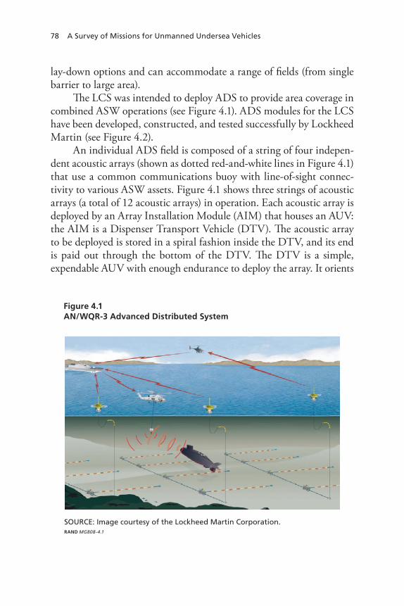
78 A Survey of Missions for Unmanned Undersea Vehicles
lay-down options and can accommodate a range of fields (from single barrier to large area).
The LCS was intended to deploy ADS to provide area coverage in combined ASW operations (see Figure 4.1). ADS modules for the LCS have been developed, constructed, and tested successfully by Lockheed Martin (see Figure 4.2).
An individual ADS field is composed of a string of four indepen-dent acoustic arrays (shown as dotted red-and-white lines in Figure 4.1) that use a common communications buoy with line-of-sight connec-tivity to various ASW assets. Figure 4.1 shows three strings of acoustic arrays (a total of 12 acoustic arrays) in operation. Each acoustic array is deployed by an Array Installation Module (AIM) that houses an AUV: the AIM is a Dispenser Transport Vehicle (DTV). The acoustic array to be deployed is stored in a spiral fashion inside the DTV, and its end is paid out through the bottom of the DTV. The DTV is a simple, expendable AUV with enough endurance to deploy the array. It orients
Figure 4.1AN/WQR-3 Advanced Distributed System
RAND MG808-4.1
SOURCE: Image courtesy of the Lockheed Martin Corporation.

evaluation of UUV Missions 79
itself to a desired bearing using a compass and deploys the array on the desired line of bearing (LOB).
To deploy ADS, four AIMs are strung together mechanically and electronically. The AIMs are launched sequentially off the stern of the LCS, resulting in the array spacing shown in Figure 4.1. Each AIM deploys a drogue parachute upon hitting the ocean surface, and the drogue slows the descent of the AIM to 1–2 kt to ensure that the AIM lands upright and to limit impact when reaching the ocean bottom. Figure 4.3 depicts the deployment of an individual ADS acoustic array, which begins with stabilization of the DTV on the ocean bottom. The AIM releases the DTV, which swims out of the AIM and begins deploying a leader cable (a connecting cable without hydrophones). The DTV completes its turn toward the preset LOB while still deploying the leader cable. The DTV begins to deploy the array when the leader cable runs out and maintains a stable attitude during this process.
Many of the technologies needed for leave-behind acoustic sensor arrays for ACINT have been developed and demonstrated. Technol-ogies for deploying leave-behind ACINT array systems from AUVs have been developed and demonstrated. Technologies for mapping the
Figure 4.2Array Installation Module and Dispenser Transport Vehicle
RAND MG808-4.2
SOURCE: Image courtesy of the Lockheed Martin Corporation.
Array installation
module
Dispenser transportvehicle

80 A Survey of Missions for Unmanned Undersea Vehicles
ocean bottom and autonomously determining appropriate locations for placing fiber-optic cables and pipelines on the ocean bottom have been demonstrated commercially. Vehicles with the payload capacity and endurance to deliver leave-behind acoustic sensor arrays have also been demonstrated commercially (Theseus is one example). ARL Penn State is now developing a new large AUV that could be capable of deploying acoustic sensor arrays for ACINT collection.
Large AUVs may also be able to deploy other leave-behind systems. For example, large AUVs could place sea mines in enemy military ports in time of war, which could deter or delay the deployment of enemy vessels from port, close ports by sinking vessels, or prevent deployed vessels from returning to port to refuel and rearm. Note that mine-laying is clearly not an ISR mission, and that leave-behind missions are not always ISR missions. The Unmanned Systems Roadmap recognizes this and treats leave-behind missions as a distinct category.15
15 In addition to agreeing that leave-behind missions should be treated separately, we sug-gest that future prioritizations of UUV missions consider ACINT, mine-laying, and other possible leave-behind missions.
Figure 4.3DTV Deployment
RAND MG808-4.3
SOURCE: Image courtesy of the Lockheed Martin Corporation.
1. DTV StabilizationAfter landing, the DTV waits for its sensors to stabilize.
4. Start Array InstallationStable attitude and heading on planned LOB.
3. DTV Turn to LOBThe DTV turns onto the planned LOB while still installing the leader cable.
2. DTV EgressRestraints are retracted and the DTV swims out and starts adjusting its ballast to trim to near neutral.

evaluation of UUV Missions 81
Specialized Mapping and Object Detection and Localization
Specialized mapping and object detection and localization, accom-plished with a mix of divers, manned vehicles, and UUVs, have been ongoing for decades. These missions have been conducted to identify weapons, wreckage, and debris. For example, divers famously located a hydrogen bomb dropped into the Mediterranean Sea in 1966 follow-ing a midair collision. In 1974, the United States attempted to recover objects of interest from a Golf-class Soviet ballistic-missile submarine. The manned deep submersible submarine NR-1 was used to map the wreckage of the space shuttle Challenger, which was lost 1986, and to recover objects of interest from the debris field. In 1991, during Opera-tion Desert Storm, the wreckage of a SCUD missile was located and components of interest were recovered from the Saudi port of Al Jubayl. At least three F-14 Tomcat fighter aircraft lost at sea have been the objects of such operations. The crash in 2000 of Alaska Airlines Flight 261 off the coast of California is another example in which specialized mapping and object detection and localization were used (to retrieve the aircraft’s flight recorder, among other things). In early 2008, two F-15C fighter aircraft over the Gulf of Mexico and their wreckage were sought via specialized mapping and object detection and localization. In summary, there has been a steady demand signal for this mission at both the classified and unclassified levels. Demand is expected to continue.
NR-1 was deactivated in November 2008. This increases the burden on UMSs. We believe that USVs may be an attractive alterna-tive to UUVs in some specialized mapping and object detection and localization missions. There is little need, for example, for clandestine operations in the Gulf of Mexico in the vicinity of a crash site.
Mine Countermeasures
The U.S. Navy and other navies have identified MCM as an area of clear military need, and U.S. Navy MCM warfare is undergoing a sig-

82 A Survey of Missions for Unmanned Undersea Vehicles
nificant transformation.16 As part of this transformation, the Navy has invested significant effort in developing UUVs for MCM and is field-ing UUVs to reduce the need for manned vessels for mine detection, classification, identification, and neutralization.
Today, the Navy uses a mix of ships, sensors, and air and marine systems for effective MCM. UUVs have demonstrated an ability to conduct surveys in support of mine warfare and MCM missions. Exist-ing UUV and USV systems have relatively long endurance (ranging from hours to days), the ability to host existing mine-detection systems, and classification and identification sensors. They have been integrated with existing support and command-and-control infrastructures.
UUVs are not capable of conducting all MCM missions. Further-more, they must be hosted by a manned platform (currently, either a submarine or a surface ship), and they require intelligent human inter-action. Note that in FY01, the Navy initiated a search-classify-map (S-C-M) small-UUV system acquisition program for the Very Shallow Water Countermeasures initiative.17 Such vehicles were to search areas of interest and classify contacts as mine-like or non–mine-like while mapping the area. Vehicles capable of reacquiring and identifying actual mines are intended to follow the S-C-M vehicles. Finally, manned or unmanned vehicles are intended to perform mine neutralization. This CONOP was motivated by two technological limits at the time: Avail-able sensors could not classify and identify mines, and multiple vehicles were needed to search, classify, map, and identify mines. In addition to being time-consuming, this CONOP also stressed vehicle-navigation capabilities in mapping and relocating objects of interest. Subsequent sensor developments have resulted in the ability to search for, classify, map, and identify mines in a single vehicle sortie. Indeed, two vehicles have independently demonstrated the capability to search for, classify,
16 U.S. Government Accountability Office, Overcoming Challenges Key to Capitalizing on Mine Countermeasures Capabilities, GAO-08-13, October 2007.17 U.S. Department of the Navy, A Navy Strategic Plan for Small Unmanned Underwater Vehicles, PMS-EOD, 2002, p. 4.

evaluation of UUV Missions 83
map, identify, and neutralize mines in a single vehicle sortie.18 This concept has obvious advantages because it minimizes the number of vehicles that must be carried shipboard and shortens the time required to neutralize mines.
MCM operations will likely become increasingly dependent on unmanned systems. The Navy appears to be shifting from dedicated MCM ships to surface ships and submarines that can host unmanned air, surface, and underwater vehicles in mission modules or similar packages. Fewer manned alternatives will be available as ship inactiva-tion and construction continues, and CONOPs and CONEMPs are expected to become more dependent on unmanned systems.
The Navy’s current MCM capability includes the following major systems:
the • Avenger-class MCM-1 ship, which is capable of minesweep-ing, mine-hunting, and mine neutralizationthe MH-53E Sea Stallion MCM helicopter, which is capable of •sweeping mechanical and influence mines and conducting mine-huntingEOD forces and SOF•the MK-4 (moored mine-hunting), MK-5 (mine recovery), MK-6 •(swimmer defense), and MK-7 (bottom mine-hunting) marine-mammal systems, which are capable of detecting buried mines and placing neutralization charges on moored, bottom, and buried mines. Although these systems are marine mammal–based, they are considered manned systems.
The Osprey-class MHC-51 coastal mine hunter was an alternative until 2007, when the last of these ships was stricken from the Naval Vessel Register.19
18 These vehicles are Saab’s Double Eagle and BAE’s Talisman M prototype. The Double Eagle can neutralize bottom mines. The Talisman M has been designed to neutralize volume and volume mines. 19 NAVSEA Shipbuilding Office, “Ship Hull Classification Symbols,” Web page, undated.

84 A Survey of Missions for Unmanned Undersea Vehicles
The main operational risks associated with using UUVs for MCM systems are the issues associated with the requirements to (1) host UUVs aboard manned platforms and (2) interact with these systems during operations. Many of the operational and technological risks associated with using UUVs for ISR are also seen when UUVs are used for MCM operations, although the need for in situ adaptation is reduced in the latter mission type. Mission compromise is an issue when conducting clandestine MCM operations.
A significant operational risk is associated with the classifica-tion and identification of mines, especially in the presence of clutter (i.e., non-mine bottom objects). This operational risk increases as the type of bottom degrades and mines are overlooked among clutter.
Anti-Submarine Warfare
Recall that the 2004 UUV Master Plan presents three categories of ASW missions for UUVs:
hold at risk—monitoring all submarines that exit a port or transit •a chokepointmaritime shield—clearing and maintaining a CSG or ESG oper-•ating area free of threat submarinesprotected passage—clearing and maintaining for a CSG or ESG •a route free of threat submarines.20
We note here that the USV Master Plan advocates and provides CONOPs for these missions.21 It also analyzes the requirements for USVs in such missions. For the protected-passage mission in particular, it shows a need for USV speeds of 20–45 kt, which is 2–3 times the speed of the surface group. For UUVs, a more realistic CONOP would have a surface ship deploy a UUV, recover it, and sprint ahead of the surface group.
20 U.S. Department of the Navy, 2004.21 U.S. Department of the Navy, 2007b, pp. 23–28.

evaluation of UUV Missions 85
We consider UUV capabilities, risks, and costs in the context of these three CONOPs. We do not attempt to assess need for these three missions. Instead, we note that current and planned ASW capabili-ties, especially against modern diesel-electric threat submarines in the context of major combat operations, appear in general to be decreasing as (1) SSNs are decommissioned more quickly than they are commis-sioned and (2) the number of ASW-capable surface ships declines.22 ASW is performed today by attack submarines, surface ships, maritime-patrol aircraft, and surveillance systems that operate as a combined or networked force. LCS and future surface platforms that are capable of hosting LCS mission modules will have an ASW mission module that includes unmanned and manned rotorcraft, a Remote Minehunting Vehicle (RMV)-type UUV/USV, and deployable sensor arrays.
The Navy’s current shipbuilding plan projects an attack- submarine force level of 48 ships and an LCS inventory of 55 ships. Delays in shipbuilding are expected to reduce the number of ASW-capable platforms, especially as platforms currently in service are retired or enter maintenance availabilities. As the Navy reduces its inventory of ASW-capable assets, either existing systems must become more capable of conducting ASW missions or the Navy must change its CONOP. One answer to this problem is to transfer some responsi-bilities from manned vessels to unmanned vehicles.
Hold at Risk
Notional capabilities associated with the hold-at-risk concept intro-duced in Chapter Two include patrolling a chokepoint 5–50 nm wide at a speed of 3–12 kt. Using a simple barrier-patrol model (described in Appendix B), we evaluated UUV effectiveness in hold-at-risk mis-sions at the width and speed conditions just described. The target was assumed to leave port at 5 kt. Using best judgment, detection and clas-sification were assumed to occur at a range of 0.25 nm (about 500 yd). The results of this analysis are shown in Figure 4.4. For the best case of
22 See Ronald O’Rourke, Navy Attack Submarine Force-Level Goal and Procurement Rate: Background and Issues for Congress, CRS Report for Congress, Order Code RL32418, June 11, 2007.

86 A Survey of Missions for Unmanned Undersea Vehicles
a barrier 5 nm long being patrolled by a UUV traveling at 12 kt, the probability of detection is less than 30 percent. Detection performance decreases more or less inversely with barrier length, declining to 1 per-cent for a 3-kt UUV patrolling a 50-nm barrier.
The Jianggezhuang submarine base near Qingdao, China, illus-trates a potentially useful niche capability for the hold-at-risk UUV mission.23 The entrance to this hardened underground facility in the western Yellow Sea is visible in the lower right portion of Figure 4.4.
A UUV operating at 3 kt outside of the mouth of such a subma-rine-base exit could establish a barrier up to half a mile long with some confidence that any contact would be a submarine. UUVs could pro-vide a “tripwire” capability not easily obtained via other ASW alterna-tives. Even a small glider, such as the Slocum Battery Glider, operating at half a knot could be effective in a tripwire barrier half a mile long (see the diagonal line in the lower left corner of Figure 4.5). However,
23 We selected the Jianggezhuang submarine base because of the quality of its image in Google Earth.
Figure 4.4UUV Effectiveness in Hold at Risk
UUV traveling at 12 ktUUV traveling at 3 kt
RAND MG808-4.4
Pro
bab
ility
of
det
ecti
on
Barrier width (nm)
454035302520151050 50
0.9
0.8
0.7
0.6
0.5
0.4
0.3
0.2
0.1
1.0
0

evaluation of UUV Missions 87
without clear linkage to a kill chain, such a tripwire might be appli-cable only in peacetime ISR missions.
The 2004 UUV Master Plan’s concept of a 20,000-lb UUV patrolling for extended periods at 12 kt is heroic in the context of cur-rent technology. The estimate of a 0.25-nm detection range determined from the analysis just described was intended to be optimistic and may not be achievable. An effective barrier could, however, be established outside a port, such as the Jianggezhuang submarine base, using a UUV operating at 0.5 kt and able to detect and classify at a range of 0.125 nm (about 250 yd). Covert launch of the UUV to minimize operational risk could be accomplished using a glider’s ability to pro-vide ranges of hundreds or thousands of miles.
Maritime Shield
Maritime-shield operations would be difficult if the CONOP proposed in the 2004 UUV Master Plan (i.e., having UUVs screen high-value units from submarines) were followed. This CONOP for UUVs is
Figure 4.5The Jianggezhuang Submarine Base
RAND MG808-4.5
SOURCE: Image obtained from Google™.
Potential UUV barrier locations

88 A Survey of Missions for Unmanned Undersea Vehicles
handicapped by UUVs’ limited search rates, autonomy issues (i.e., false alarms and the need for outside assistance to conduct contact classifica-tion), and a limited ability for weapons engagement.
However, UUVs could be used effectively as decoys, clutter, noise, or other “confuser” missions. Submarines use primarily acoustic sen-sors to detect, classify, and localize ships. Acoustic propagation has the advantage that after a few kilometers, radiated noise is well approxi-mated by a point source (such as a transducer). UUVs could provide lower source-level signals, with reasonable fidelity, to increase the appar-ent contact density or noise, thereby degrading signal-to-noise ratios in acoustic-search or analysis bands. The EMATT demonstrates that such a device could be developed.
The development of UUVs capable of participating in a screen or prosecution-type CONOP would be extremely challenging. A con-fuser or “clutter” approach, however, entails a relatively low level of technological risk. Operational risk would increase over time as adver-sary submarines learned how to distinguish between real and simu-lated ships.
Protected Passage
Qualitatively speaking, UUVs are poorly suited to protected-passage ASW. As stated previously, ONR has noted that the longest-range engagements by threat submarines against high-value units in pas-sage will be conducted using anti-ship cruise missiles (ASCMs), which enable effective engagement from launch-submarine ranges of up to 10 nm.24 The CONOP for protected passage can therefore be sum-marized as protecting high-value units from attack for distances out to the maximum effective engagement range of ASCMs. ONR states that this is best accomplished by rapidly deploying distributed sensor systems and notes that sensor-system deployments need not be covert: Speed of deployment is more important than covertness due to the short lifespan of the period of vulnerability. ONR also observes that effective defense will require rapid localization and attack in order to engage an adversary submarine before it can conduct an attack.
24 Herr, 2007.

evaluation of UUV Missions 89
ONR’s observations suggest that the need to rapidly deploy sys-tems capable of rapid localization and attack does not match UUV capabilities. UUVs can be relatively slow to deploy, are generally inca-pable of rapid localization and attack, and are generally unable to pro-vide data that leads to rapid localization and attack. Furthermore, UUV stealth is not advantageous here. We thus conclude that UUVs are not well-suited to protected-passage ASW.
Quantitatively, protected-passage ASW entails sanitizing the area along the position of intended movement (PIM) at the rate of about 300 nm2 per hour. To see this, if the requirement is to sanitize an area 10 nm to either side of the PIM, that area has a front width of 20 nm. This front sweeps like a piston along the PIM at the speed of the strike group (approximately 15 kt). A 20-nm front sweeping forward at about 15 kt therefore creates a search-rate requirement of approximately 300 nm2 per hour. Assuming optimistically once again that a UUV can operate at 12 kt with a half-mile sweep width, a single UUV could sweep at most 6 nm2 per hour. This means that more than 50 UUVs operating simultaneously would be required to collectively search 300 nm2 per hour. Still more UUVs would be required for refu-eling and refurbishment. To keep pace with the advancing strike group, UUVs would have to deploy ahead of that group then be retrieved and once again repositioned ahead of the strike group. Put another way, one or two UUVs (from an LCS, for example) would generate less than 1 percent of the needed capability.
Note that UUVs’ limited acoustic-processing capability would likely make high false-alarm rates an issue.
Furthermore, host ships would need to deploy and recover UUVs in the threat area, thereby increasing their own vulnerability. It is not clear that the benefit of using UUVs to protect a strike group in such operations would outweigh the risk to host platforms.
The protected-passage CONOP is fraught with technical, opera-tional, and cost risks. The predominant technological risk is develop-ing a UUV with the speed and endurance required for the mission, the ability to be launched and recovered quickly, turnaround times adequate to support the mission, adequate detection capabilities, and

90 A Survey of Missions for Unmanned Undersea Vehicles
acceptable false-alarm rates.25 Operational risks (i.e., the kill-chain issues and risks to host platforms) were described above. Finally, the RDT&E costs associated with new propulsion technologies and vehi-cles would be high, as would the procurement costs associated with new vehicles and dedicated host platforms. This mission is therefore not recommended.
Inspection/Identification
Since the October 2000 attack on the USS Cole (DDG-67) in Yemen, the Navy has recognized the terrorist threat to its ships. Underwater inspection/identification is a primary defense against such threats. The Navy has also long recognized the need for ship inspections following groundings and collisions with fixed objects and other ships. Ship hulls are also inspected regularly for corrosion and fouling, which occur naturally over time and reduce ship performance and hull integrity.26 Periodic inspections and surveys of military and commercial vessels are performed to assess material conditions and the need for cleaning, preservation, repair, or restoration.
Traditionally, hull surveys and inspections have been performed by drydocking ships or using dive teams. Drydocking is not an option during overseas operations, however, and dive operations are expensive relative to using UUVs and entail a measure of diver risk. The Navy has accepted the performance risk associated with using UUVs for mainte-nance- and repair-related underwater inspection and survey tasks. It is expected that the use of UUVs in these missions will continue, so we consider this an acceptable UUV mission.
25 Today’s AUVs operate at speeds up to approximately 6 kt for extended periods. For a given form factor, increasing sustained speed from 6 kt to 15 kt requires about a 15-fold increase in power. For a given temporal endurance, stored energy must be increased correspondingly. The use of larger vehicles to achieve higher speed can create handling problems. We provide a simple engineering model in Appendix B to enable exploration of this topic.26 This is true of commercial as well as military vessels. The American Bureau of Shipping requires two hull inspections every five years. One of these inspections may be performed without drydocking.

evaluation of UUV Missions 91
When ships must be secured for divers, dive operations also require more personnel than do UUV operations, which can be per-formed with as few as one or two people. The cost effectiveness of using UUVs instead of divers is demonstrated by the increasing use of UUVs for ship-hull inspection in the commercial and homeland-security sec-tors. As a result, the Navy is increasingly able to tap into AUV and ROV COTS solutions for inspection/identification.
Oceanography
Oceanography missions are described under “Intelligence, Surveil-lance, and Reconnaissance,” above.
Communications/Navigation Network Nodes
The 2005 Anti-Submarine Warfare Concept of Operations for the 21st Century,27 developed by Task Force ASW, considers near-term and long-term transformations for ASW. In the long term, ASW must move from “platform-intensive” to “sensor-rich” operations. Two criti-cal long-term needs are distributed netted sensors and advanced data relays. The Anti-Submarine Warfare Concept of Operations for the 21st Century explicitly recognizes communications roles for AUVs in their capacity to serve as communications platforms.
We see little or no value, however, in most of the UUV com-munications/navigation missions advocated in the 2004 UUV Master Plan. In particular, we see no need for the navigation mission that involves providing lane dividers for amphibious operations, since pro-cedures developed by the U.S. Marine Corps obviate the need for lane markers of any form. During RAND interviews, senior Marines expe-rienced in planning and conducting amphibious operations dismissed the use of UUVs as lane markers in amphibious operations. Similarly,
27 The full reference is U.S. Department of the Navy, Anti-Submarine Warfare, Concept of Operations for the 21st Century, February 3, 2005.

92 A Survey of Missions for Unmanned Undersea Vehicles
there appears to be no significant advantage to using UUVs to provide communications support for SOF divers. In this case, the significant unwanted complexity inherent in integrating UUVs into SOF dive operations outweighs any possible benefits. Detection risks inherent in operating unmanned vehicles with exposed masts near SOF divers are also problematic.
Operational considerations reduce the need for other advocated UUV communications/navigation missions. Consider, for example, the mission of providing an inverted (antenna-to-surface) GPS capabil-ity that would allow undersea platforms to access navigation data with-out exposing themselves. It is easy to imagine, for example, an SSN’s need for GPS-quality navigation.28 Recall the need for surface ships to deploy navigation UUVs shortly before those UUVs are needed, then consider whether conditions that make exposure of a submarine mast unacceptable would ever make using a surface ship to deploy a UUV ahead of the SSN acceptable. The answer is probably no. There are further issues. For example, what ships would deploy the navigation UUVs? Would they need to be dedicated to that mission in order to ensure their availability?
Gateway buoys, designed to perform many of the communica-tions/navigation missions advocated for UUVs, demonstrate by their existence the need for those missions.29 Gateway buoys can be deployed from various platforms (including SSNs), and they are reliable and far less expensive than sophisticated UUVs. A UUV deployed several days ahead of an SSN could not be replaced in the event of failure, but an ejected gateway buoy could be replaced quickly in the (less likely) event of failure. Gateway buoys can provide low-aspect deployed antennas and can also serve as transponders. In short, when such a capability is required by SSNs, ejected, short-lived, expendable gateway buoys would be more reliable, dependable, and clandestine than UUVs deployed in
28 Today’s SSNs have sophisticated INSs that can maintain navigational accuracy for sig-nificant periods between GPS updates. AUVs using Doppler Velocity Log technology can also maintain GPS-quality navigation. Moreover, GPS receivers that can operate at shallow depths underwater have been demonstrated. 29 Gateway buoys were described in Chapter Three.
evaluation of UUV Missions 93
the area by surface ships. Taking the cost of surface-ship operations into account, we see that using submarine-ejected gateway buoys rather than UUVs would also significantly reduce costs.
The High-Frequency Internet Protocol (HFIP) program, which has demonstrated the ability of submarines to conduct two-way com-munications while operating at depth and speed, is another option.30 HFIP capability was demonstrated during trials of the USS Harry S. Truman CSG. “Deep Siren” technology being developed by Raytheon may offer another solution to the problem of communicating with SSNs at depth and speed.31
Returning to the concept of using UUVs for communications relays, we see that all UUV communications/navigation missions require host vessels to deploy UUVs. What kind of vessels would serve as hosts? How many would be needed to ensure availability? In consid-ering cost, ship equipment must be factored in.
Finally, we return to the matter of RDT&E funds for UUVs. Do communications/navigation missions merit a portion of limited RDT&E budgets for UUVs? The 2004 UUV Master Plan ranks need for these missions as sixth out of nine; the Unmanned Systems Roadmap gives them a similarly low ranking. Our findings—that two specific missions (lane markers and communications support for SOF divers) should be dismissed, that others pose serious operational and cost issues, and that there are more-reliable, dependable, and clandestine alternatives to UUVs launched from surface ships—do not encourage a higher ranking for these missions.
Payload Delivery
In the payload-delivery concept, which in this book includes SOF resupply, a UUV is used as a truck to deliver a payload. This concept
30 Defense Systems Daily, “US Navy Achieves Two-Way, Networked Connectivity,” Web page, February 29, 2008.31 Defense News, “In Deep Water: Improved Sub Communications Sought,” Web page, February 11, 2008.

94 A Survey of Missions for Unmanned Undersea Vehicles
was demonstrated in 2003 during Exercise Giant Shadow.32 Alterna-tives to payload delivery by UUVs include manned and unmanned surface and air platforms.
Most UUVs are designed to be neutrally buoyant, meaning that the vehicle weight must equal the weight of the volume of water the vehicle displaces. Payload weight and volume can differ from the weight of the displaced volume of water as long as the platform’s over-all weight approximately equals the weight of the water the vehicle displaces. Small trim systems can adjust for temperature and salinity variations. Although vehicles can be scaled up to carry large volumes, the diameter limits imposed on UUVs to simplify launch and recovery combine with weight limits to restrict the utility of smaller UUVs for this mission. The Navy has recognized this and recommended only larger-diameter UUVs for this mission. Note that a 2007 analysis of alternatives rejected the concept of using UUVs to resupply SEALs in SDVs.33
The technical risk for logistics-type payloads that have been pre-viously qualified for submarine or for oceanic use (e.g., oceanographic survey instruments) is low. The expected payload volume (4–6 ft3) of UUVs the size of a heavy torpedo illustrates possible payload packages.34 Additionally, payloads can only be positioned or pre-positioned under water, entailing attendant recovery problems and risk of detection.
Information Operations
Chapter Two described two distinct classes of IO for UUVs from the 2004 UUV Master Plan:
32 J. E. Dzielski, M. J. Bregar, and D. L. McDowell, “NAVOCEANO Seahorse AUV Par-ticipation in the GIANT SHADOW Experiment,” Oceans Proceedings, Vol. 2, September 22–26, 2003, pp. 1127–1131.33 Three of the authors of this book participated in that recent SDV analysis of alternatives.34 Appendix A describes payload volumes for various UUV sizes.

evaluation of UUV Missions 95
Jam or inject false data into enemy communications or computer •networks, or conduct denial-of-service operations.Act as submarine decoys.•
We treat these missions separately below.
Network Information Operations
IO missions considered for UUVs include jamming or injecting false data into enemy communications or network systems and conducting denial-of-service operations. Typically, the technology, methods, and tactics surrounding IO are highly classified. The Unmanned Systems Roadmap lists reconnaissance operations as the most important use for unmanned systems and gives IO lower priority.35 The likelihood of success of IO operations can be unpredictable. For example, a pro-cedure successful against a system one week may be unsuccessful the following week due to such considerations as system reconfiguration, password changes, and the introduction of new security procedures. Probing efforts may be detected and thereby elicit unwanted responses. Furthermore, responses to successful network IO may elicit unpredict-able reactions. Will the adversary react with confusion? Retaliate in kind? React kinetically?
Reiterating the above observations, the general need for jamming or injecting false data into enemy communications systems or conduct-ing denial-of-service operations is not clear in part because the results of such actions are unpredictable.
UUVs could offer an advantage in such missions because they can approach the networks that must be jammed. UUVs are disadvan-taged, however, relative to other platforms in terms of their (1) lack of human presence and creativity and (2) paucity of power for jamming. (In the latter regard, USVs powered by diesel engines may be better suited than other UUVs for jamming operations.) Moreover, poten-tial geometry advantages do not apply to the injection of false data or the other desired operations. Even worse, UUVs are disadvantaged in terms of their mast height: Even relatively large UUVs may have masts
35 Office of the Secretary of Defense, 2007b, p. 23.

96 A Survey of Missions for Unmanned Undersea Vehicles
only a few feet high, which severely restricts their horizon and limits their ability to reach target networks.
Alternatives to using UUVs for network IO include using manned and unmanned aircraft, manned and unmanned surface craft, and submarines, or conducting operations against land lines. Some of these alternatives appear to have significant advantages over UUVs for net-work IO. These advantages include greater persistence, a less limited field of regard, greater power, and a creative human presence. In the context of all of the above, we do not recommend this mission for UUVs.
Decoy Operations
The 2004 UUV Master Plan describes three distinct CONEMPs for the use of UUVs as submarine decoys:
Impede enemy maritime operations by increasing fear of attack by •a nonexistent or minimal U.S. submarine threat.Enhance the safety of friendly submarines by causing adversaries •to dilute their ASW efforts.Cause enemies to alter their plans (e.g., enemies could decide not •to operate in an area thought to be dangerous).36
These CONEMPs share the supposition that adversaries of inter-est will be able to detect and classify U.S. SSNs. In reality, however, very few potential adversaries have a significant capability to detect and identify U.S. SSNs. The first and third CONEMPs further presuppose that U.S. SSNs will be able to threaten attacking forces. If such adver-saries wish to attack high-value units (such as aircraft carriers), they may use anti-ship cruise missiles launched from aircraft or shore bat-teries to do so. If they launch attacks using surface ships or submarines, however, problems with these CONEMPs become immediately appar-ent. For example, what level of perceived threat would be needed to deter such attacks? How can the level of perceived threat from decoys be predicted?
36 U.S. Department of the Navy, 2004.

evaluation of UUV Missions 97
The second CONEMP is also problematic. It presupposes that U.S. SSNs will be the object of an adversary’s attack. Few potential adversaries are systematically able to detect and classify U.S. SSNs, however, and even fewer could mount an effective offensive campaign against U.S. SSNs. Another problem is that UUV host platforms would be less able than U.S. SSNs to defend themselves in the event of an attack.
Both the 2004 UUV Master Plan and the Unmanned Systems Roadmap place decoy operations nearly last in their prioritized lists of needs. In light of the considerations described above, we do not believe this mission deserves higher priority, and we do not recommend it.
Time-Critical Strike
A broad need for TCS in future wars is expected. However, the goal of using UUVs to achieve a proposed sensor-to-shooter time line measured in seconds appears unrealistic. Furthermore, implementation of this concept, even if a longer time line were allowed, would require viola-tion or abrogation of the Strategic Arms Reduction Treaty (START)—a high price to pay for an operational capability that entails high tech-nical and operational risks.
A 2002 assessment of ONR technologies found that improved decision aids are needed to accelerate the required analyses of poten-tial collateral or unintended damage that must accompany each target nomination before weapon release can be authorized.37 The types of fires permitted vary according to the level of conflict; in some instances, there will be requirements for highly precise fires or temporary dis-abling techniques and technology (such as the use of electronic war-fare). The level of collateral damage to humans and property caused by attacking any target is a cause for concern for humanitarian and polit-ical reasons. Issues of collateral damage take on greater importance
37 Committee for the Review of ONR’s Air and Surface Weapons Technology, 2002 Assess-ment of the Office of Naval Research’s Air and Surface Weapons Technology Program, National Research Council, December 2002.

98 A Survey of Missions for Unmanned Undersea Vehicles
as military targets are integrated into civilian surroundings to deter attack. Additionally, fratricide must be avoided and attention must be paid to rules of engagement.
The 2002 study also identified a need for improved sensor sys-tems and processing algorithms to allow more-efficient discrimination between targets and decoys and between military and civilian targets. It also pointed to the need for a new or expanded CONOP for a preci-sion, high-speed, surface-to-surface weapon that can reach its intended target from long standoff distances in times that are short compared with the dwell times of mobile or relocatable targets. Finally, it identi-fied a need for improved weapon-assignment capabilities for the effi-cient use of TCS assets. To these requirements we add the need for joint fires and airspace issues to be coordinated.
Given current and planned technologies, a sensor-to-shooter time line measured in seconds appears not to be achievable regardless of weapon time-of-flight. Furthermore, the value of reducing sensor-to-shooter time lines to seconds is questionable.
Finally, note that Article V, ¶18, of the 1994 Strategic Arms Reduction Treaty states that
each Party undertakes not to produce, test, or deploy: (a) ballistic missiles with a range in excess of 600 kilometers, or launchers of such missiles, for installation on waterborne vehicles, including free-floating launchers, other than submarines. This obligation shall not require changes in current ballistic missile storage, trans-port, loading, or unloading practices; (b) launchers of ballistic or cruise missiles for emplacement on or for tethering to the ocean floor, the seabed, or the beds of internal waters and inland waters, or for emplacement in or for tethering to the subsoil thereof, or mobile launchers of such missiles that move only in contact with the ocean floor, the seabed, or the beds of internal waters and inland waters, or missiles for such launchers. This obligation shall apply to all areas of the ocean floor and the seabed, including the seabed zone referred to in Articles I and II of the Treaty on the Prohibition of the Emplacement of Nuclear Weapons and Other

evaluation of UUV Missions 99
Weapons of Mass Destruction on the Seabed and the Ocean Floor and in the Subsoil Thereof of February 11, 1971 . . . .38
Simply put, this UUV mission violates the START treaty. The deploy-ment of UUVs for TCS would trigger specific protocols outlined in START I because the treaty prohibits such exotic weapons from being developed or deployed.39
There is no known UUV capability to transport or launch mis-siles. Thus, there is no basis for estimating the cost of developing a UUV for TCS, a missile to be fired from that UUV, or a missile can-ister. Assuming the U.S. abrogates START, a rough order-of-magni-tude estimate suggests that a single round for TCS would cost about $100 million. A number of alternatives to UUVs for TCS, including manned aircraft and cruise missiles, are in operation.
We believe that developing a suitable UUV specialized for TCS entails significant technical risk. Similarly, we believe that developing a specialized weapon (possibly one that is hypersonic and capable of subsea launch) would prove very challenging. The command, control, and communications problems associated with using a UUV (that may sit on the bottom) for the TCS missions would likely be daunting.
Such a mission also exhibits operational risks, such as those posed to the vessels that maintain the UUVs loitering in the water column. The United States has signed international conventions that forbid laying armed devices in international waters in peacetime unless such devices are continuously monitored and the international shipping community is warned of their location. This means that TCS involving UUVs that sit on the bottom or are launched from a system deployed
38 Office of the Under Secretary of Defense for Acquisition, Technology, and Logistics, “Treaty Compliance, Strategic Arms Reduction Treaty (START I),” Web page, December 5, 1994. 39 Office of the Under Secretary of Defense for Acquisition, Technology, and Logistics, 1994. Tethered weapons or weapons that move in contact with the ocean floor are specifi-cally mentioned. During negotiations, the United States maintained that such exotic or novel platforms, unless developed as nuclear-capable systems, were not captured by the treaty. A commission established by the treaty considers such matters.

100 A Survey of Missions for Unmanned Undersea Vehicles
on the bottom may be impossible. For all of these reasons, we do not recommend the mission.
Undersea Test Platforms
Undersea test platforms are needed for new-design submarines or in the modification of existing submarine designs. Computational hydro-dynamics can accurately predict hydrodynamic flow for submarines in steady operations. The hydrodynamic-flow problems associated with unsteady flow (such as during turns) are intractable using computa-tional hydrodynamics. Similarly, existing hydrodynamic-test facili-ties can predict steady flows, but they cannot predict unsteady flows. This provided the original reason for using LSVs in tests. The question now is whether dedicated LSVs are required to test submarine designs. Manned vehicles and large AUVs can be used to test new submarine designs, and crewing a test vehicle would reduce the need for complex autonomous systems and, perhaps, increase flexibility in testing. This modest advantage is offset, however, by the fact that a manned large-scale test vehicle would be designated a submarine and thus fall under SUBSAFE or P9290 construction requirements. Experience has dem-onstrated that these requirements would significantly increase con-struction cost and time.
Large, multipurpose AUVs may be a cost-saving alternative to LSVs. Additionally, whenever testers want to avoid trying a risky maneuver with a one-of-a-kind LSV, a relatively inexpensive AUV could be used instead. As noted earlier, ARL Penn State is construct-ing a large AUV that is the right size for this mission. At one-eighth scale, this AUV would need to achieve a speed of 4–5 kt—a require-ment easily met. Its intelligent controller, which is based on current technology, could easily support test requirements.

evaluation of UUV Missions 101
Submarine Search and Rescue
UUV capability for SSAR has been demonstrated several times, begin-ning with the successful rescues of the crew of the two-man submers-ible Pisces II and the Russian DSRV Priz. U.S. and international invest-ments in SSAR operations reflect the need for such a capability.
A demonstrated capability for SSAR using ROVs resides at the U.S. Navy’s Unmanned Vehicle Detachment, Naval Air Station, North Island, Calif. The alternatives to ROVs for SSAR are DSRVs and divers. Divers can perform components of SSAR in relatively shal-low water conditions, and in such cases, ROVs could arrive at the site of downed submarines ahead of divers to prepare the site. DSRV-1 Mystic is the Navy’s only operational DSRV. It will be decommissioned soon, and no replacement is planned.
ASW Training
ASW training is essential to maintaining proficiency in ASW. Despite their lack of fidelity, ASW classroom training and computer-driven simulators have value. However, they cannot replace ASW training at sea. U.S. Navy SSNs have limited availability for use in such training, so U.S. Navy crews gain experience by working with foreign navies or operating leased foreign submarines.40 The ongoing procurement of EMATTs testifies to the capabilities and cost-effectiveness associated with using AUVs for ASW training.
Monitoring Undersea Infrastructure
The United States is dependent on its undersea infrastructure. Trans-oceanic cables, for example, are vital to the country’s communica-tions capabilities, since space-based systems cannot provide the needed
40 For example, the Swedish government agreed in 2004 to lease a modern Gotland-class submarine and its crew of 25 to the U.S. Navy as a training submarine.

102 A Survey of Missions for Unmanned Undersea Vehicles
bandwidth.41 Undersea cables are, however, vulnerable to accidents, attacks by marine animals, and malfeasance. The Navy has installed and currently operates undersea ranges around the world. The primary function of these ranges is to provide track data and sound measure-ments for undersea-warfare vehicles and systems in support of fleet training and test and evaluation. For example, the Naval Underwa-ter Warfare Center operates the Dabob Bay Range Complex and the Atlantic Undersea Test and Evaluation Center. These sites are aging, however, and components need to be inspected for failures. The Navy’s undersea-surveillance systems, which were installed beginning in the 1950s, are also aging and vulnerable to malfeasance.
Manned and unmanned vehicles are seen as the only alternatives for monitoring U.S. undersea infrastructure. No means of monitor-ing cables from the shore, for example, is seen. NR-1, the Navy’s only nuclear deep-diving research submarine capable of this mission, was inactivated in November 2008. There is no plan to replace NR-1 with another deep-diving submarine. This leaves unmanned vehicles as the only alternative for this mission.
Recall that in August and September of 1999, an Aqua Explorer 2 inspected 420 km (227 nm) of submarine cable that crosses the Taiwan Strait. The Aqua Explorer 2 has since been replaced by the more capable Aqua Explorer 2000, which can track undersea cables, monitor their depth, and return still-camera images and continuous-video records of sea-bottom conditions and laid cables. Two Aqua Explorer 2000 AUVs are operated by the Kokusai Marine Engineering Corporation to inspect fiber-optic cables. A U.S. Navy mission could be conducted by contracting with an AUV operator or by buying or leasing a vehicle similar to the Aqua Explorer 2000.
41 See Frank W. Lacroix, Robert W. Button, Stuart E. Johnson, and John R. Wise, A Concept of Operations for a New Deep-Diving Submarine, Santa Monica, Calif.: RAND Corporation, MR-1395-NAVY, 2002, Appendix I, which describes in detail bandwidth issues as well as the vulnerabilities of fiber-optic cables. Incidents in 2008, which included three cables being cut off in three days, demonstrated the vulnerability of such cables. See Elham Nakhlawi, Mustafa Al Arab, Caroline Faraj, Tess Eastment, Aneesh Raman, and Brad Lendon, “Third Undersea Internet Cable Cut in Mideast,” CNN, February 1, 2008.

103
ChApter FIVe
Summary and Recommendations
Through its examination of existing and planned UUVs, this limited study has described UUV capabilities and critical technologies. Instead of summarizing that technical information in this chapter, we focus on critical findings on the topic of autonomy. Autonomy will be one of the greatest challenges associated with fielding AUVs for advocated mis-sions. This will be particularly true in advocated intelligence-collection missions. More generally, developing autonomy that provides the situ-ational awareness that AUVs need to operate in high-threat areas or where there is a high risk of incidental detection (e.g., by fishermen or fishing nets) will be another challenge. Autonomy and bandwidth form a tradespace in which onboard autonomy is traded for reachback capa-bility, and vice-versa. However, bandwidth is limited, and the commu-nications options open to AUVs tend to be slow. Moreover, there are stealth issues associated with operating AUVs with masts exposed and broadcasting for long periods. These stealth issues can spill over to host vessels, such as SSNs, even when AUVs are not reaching back to them because they indicate host-vessel presence. These stealth issues also tend to make USVs more attractive as signature differences between UUVs and USVs erode. USVs also retain advantages in terms of asset avail-ability, retasking, and persistence.
The balance of this chapter addresses master plans and roadmaps for UUVs, missions from the 2004 UUV Master Plan, and UMS pro-grams. It closes with recommendations.
104 A Survey of Missions for Unmanned Undersea Vehicles
Unmanned Maritime System Master Plans and Roadmaps
The FY94 DoD Appropriation Act directed OSD and the Navy to (1) establish priorities among various proposed UUV programs, (2) focus on near-term MCM issues, and (3) establish affordable, cost-effective programs.1 The Navy’s UUV plans were accordingly restruc-tured under the 1994 UUV Program Plan,2 which established a clan-destine, near-term mine-reconnaissance capability as the Navy’s top UUV priority; a long term-mine reconnaissance-system as its second priority; the conduct of surveillance, intelligence, and tactical ocean-ography missions as its third priority; and exploring advanced UUV designs for the future as its fourth priority.3
The Navy issued its first UUV Master Plan in 2000. This plan expanded the set of missions advocated for UUVs beyond those in the UUV Program Plan. The Navy subsequently updated the UUV Master Plan in 2004, significantly expanding the list of advocated mis-sions for UUVs to more than 40. Of these over 40 advocated missions, 20 were novel, including such missions as using UUVs to (1) serve as lane markers for amphibious assaults, (2) provide low-profile antennas for communication, and (3) conduct TCS. Novel missions often entail high levels of technical and operational risk and significant RDT&E efforts.
Needs for UUV missions described in the 2004 UUV Master Plan were inferred by its authors from Sea Power 21 documents, and the need for a general capability was understood to imply a need for that capability as provided by UUVs. For example, a broad need for persistent ISR was interpreted as a need for persistent ISR from UUVs. Cost, operational, and technical risks and legal issues are not explicitly addressed in the 2004 UUV Master Plan. The TCS mission in particu-lar appears to violate START.
1 Federation of American Scientists, “UUV Program Plan,” Web page, undated.2 The 2004 UUV Master Plan overviews on p. xvii the 1994 UUV Program Plan, the 2000 UUV Master Plan, and the 2002 Small UUV Strategic Plan.3 U.S. Department of the Navy, 2001a, p. 97.

Summary and recommendations 105
The 2004 UUV Master Plan offers many missions without asso-ciated CONOPs or CONEMPs. Performance requirements are also not always established. This lack of CONOPs, CONEMPs, or per-formance requirements hampers evaluation of missions. Also, we view some of the document’s stated performance objectives as unrealistic.4
The 2004 UUV Master Plan considers only traditional (torpedo-like) AUVs and identifies four general classes of AUVs. These classes are intended to leverage existing hardware and handling, launcher, and recovery equipment and infrastructure:
The man-portable class.• These vehicles displace approximately 25–100 lb and have an endurance of 10–20 hours. There is no specific hull shape for this class.The light-weight vehicle (LwV) class.• These vehicles nominally have 12.75-inch diameters and displace approximately 500 lb. Their payloads are intended to be six to twelve times larger than those of the man-portable class. Their endurance is intended to double that provided by the man-portable class.The hwV class.• These vehicles nominally have 21-inch diam-eters and displace approximately 3,000 lb. This class is intended to improve capability by a factor of two over the LWV class. The HWV class includes submarine-compatible vehicles.The large vehicle class.• Once developed, these vehicles will dis-place approximately 10 long-tons and will be compatible for use with both surface ships (i.e., LCS) and submarines (i.e., SSNs with a hangar or a “plug” and nuclear-powered guided-missile submarines [SSGNs]).5
4 For example, speeds of up to 12 kt—roughly twice the best cruise speed of current UUVs—are advocated. With power increasing roughly with the cube of speed, and assum-ing that planned form factors do not change, doubling speed implies an eight-fold increase in both power density and propulsion horsepower. No means are seen to achieve such power densities.5 U.S. Department of the Navy, 2004, pp. xxii–xxiii. In this context, a hangar is a dry deck shelter (DDS), a deck-mounted cylindrical shelter large enough to house a SEAL Delivery Vehicle (SDV). The USS Jimmy Carter (SSN-23) is the only SSN to date with a plug to extend its length and add volume. The SSGN is a converted Ohio-class fleet ballistic-missile subma-rine modified to launch Tomahawk cruise missiles and support special operations.
106 A Survey of Missions for Unmanned Undersea Vehicles
Gliders, crawlers, and ROVs are not treated in the 2004 UUV Master Plan, but the Navy has been developing gliders since 1995 and is now developing a new generation of gliders for ASW. Crawlers may be an attractive alternative to AUVs for the advocated mission of mechan-ically sweeping mines. ROVs are critical to SAR operations (such as for submarines in distress), the recovery of forensic evidence (such as flight recorders), and the examination of wrecks (such as the Japanese fishing vessel lost in a collision with the USS Greenville [SSN 772] in 2001). They are also an attractive option for the missions of inspecting ship hulls for damage and identifying foreign objects attached to ship hulls.
In July 2007, the Navy issued The Navy Unmanned Surface Vehi-cle (USV) Master Plan. This publication goes further than the UUV Master Plan in defining operational objectives and CONOPs. It also considers at some length the technical issue of the tradespace between autonomy and bandwidth. In some instances, it presents requirements derived from simple analytic tools. Among the missions it advocates for USVs are
strategic and tactical intelligence collection (i.e., SIGINT, ELINT, •MASINT, IMINT, and METOC intelligence)CBNRE detection and localization above and below the ocean •surfacenear-land and harbor monitoring•deployment of leave-behind surveillance sensors or sensor arrays•specialized mapping and object detection and localization•nonlethal and lethal threat deterrence•“riverine” operations, such as monitoring civilian boat traffic on •inland waterways for threat-personnel movements, contraband, or threat-weaponry smuggling, and similar undesirable activities.6
In December 2007, OSD issued the Unmanned Systems Road-map, which integrates individual roadmaps and master plans for UASs, UGVs, UUVs, and USVs. It also explicitly treats such topics as
6 U.S. Department of the Navy, 2007b, p. 32.

Summary and recommendations 107
technology challenges and legal issues. Note that, like the 2004 UUV Master Plan, the Unmanned Systems Roadmap does not discuss gliders or ROVs.
Missions from the 2004 UUV Master Plan
The 2004 UUV Master Plan presents nine missions for UUVs, and these are further divided into multiple subsets. For example, the highest priority UUV mission is ISR, which includes the following subsets:
persistent and tactical intelligence collection above and below the •ocean surface, including SIGINT, ELINT, MASINT, IMINT, and METOCCBNRE detection and localization above and below the ocean •surfacenear-land and harbor monitoring•deployment of leave-behind surveillance sensors or sensor arrays•specialized mapping and object detection and localization.• 7
Note that strategic and tactical SIGINT, ELINT, MASINT, and IMINT and METOC (above and below the surface) are treated as a single mission subset.8 The total number of missions, including subsets, varies depending on the level of disaggregation applied; complete dis-aggregation yields more than 50 missions.
Because collected intelligence must be passed to the operators who teleoperate AUVs, the intelligence missions planned for the Mission-Reconfigurable Unmanned Undersea Vehicle System (MRUUVS) will require either technologically risky improvements in AUV autonomy or significant bandwidth.9 Concepts for teleoperating AUVs in intel-
7 U.S. Department of the Navy, 2004, p. 9.8 The term acoustic intelligence and its ACINT acronym appear in the 2004 UUV Master Plan’s list of abbreviations, but nowhere else in that document. Our study shows that signifi-cant progress has been made toward deploying ACINT systems from AUVs. 9 U.S. Department of the Navy, 2007b, pp. 70–71, illuminates this problem.

108 A Survey of Missions for Unmanned Undersea Vehicles
ligence missions call into question the suitability of conducting these missions from SSNs. Expanding on this, we find that SIGINT, ELINT, MASINT, and IMINT missions requiring a man in the loop might, in fact, be performed better by USVs. On the topic of ISR missions, the USV Master Plan notes,
while the UUV option provides stealth beyond that associated with a USV, Semi-Submersible Vehicles (SSVs) can provide a nearly identical stealth profile, given that the ISR mission by defi-nition requires extensive mast or antenna exposure.10
It also notes advantages for USVs in terms of availability, retasking, and persistence.
The remarkable expansion of desired UUV capabilities between 1994 and 2004 has outstripped both the development of actual UUV capabilities and expected funding for future UUV development. Although technological progress has been achieved in UUV programs, many of today’s most successful UUVs are modified science or com-mercial systems. There is concern that the pool of science and commer-cial UUVs that can serve as a basis for future DoD UUV development has been drained. Accordingly, further RDT&E progress may come with a higher price tag.
Unmanned Maritime System Programs
An average annual budget of $71 million is planned for UMS RDT&E.11 For perspective, see Figure 5.1, which compares the FY07–13 UAS, UGV, and UMS budgets. The UMS budget, a mere fraction of the other budgets, includes the budgets for UUVs and USVs.
Planned levels of RDT&E for UUVs will not support the nine sets of UUV missions advocated in the 2004 UUV Master Plan; it is doubtful that even the top priority set of advocated missions (ISR) can
10 U.S. Department of the Navy, 2007b, p. 32.11 Office of the Secretary of Defense, 2007b, p. 10.

Summary and recommendations 109
be supported.12 This is of particular interest because the second-priority set of missions is MCM operations, which have been the focus of UUV development for the Navy since 1994. In other words, if UUV devel-opment were pursued according to the priority presented in the 2004 UUV Master Plan, the Navy would need to give up what has been its top mission for UUVs since 1994.
The AN/WLD-1 RMS is a USV recently accepted by the Navy that is currently in low initial-rate production. A diesel-powered system, the RMS offers over 14 hours of continuous operation at 12 kt, which is roughly twice the speed of current AUVs, as noted above. Although not
12 To illustrate, U.S. Department of the Navy, Fiscal Year (FY) 2008/2009 Budget Estimates: Justification of Estimates, Research, Development, Test & Evaluation, Navy, Budget Activ-ity 7, February 2007a, p. 39, shows that costs related to MRUUVS development alone in FY06–09 averaged $22.66 million per year. These costs reflect continued pre–milestone B component development, capability demonstration, Littoral Precision Underwater Map-ping (L-PUMA) risk-reduction efforts, sea tests to demonstrate recovery-arm capability, and acquisition planning for the 21-inch MRUUVS program. It does not include vehicle acquisition.
Figure 5.1DoD Funding for Unmanned Systems
RAND MG808-5.1
FY20
07–1
3 p
resi
den
t’s
bu
dg
et (
$B)
UAS UGV UMS
20
15
10
5
25
0
SOURCE: Office of the Secretary of Defense, 2007b, p. 10.
O&MPROCRDT&E

110 A Survey of Missions for Unmanned Undersea Vehicles
as covert as AUVs, the RMS presents advantages other than exceptional speed and endurance, including continuous GPS navigation and com-munication. Continuous GPS navigation ensures that RMS navigation is as accurate as possible. Continuous capability to communicate offers the best possible capability to send updates to operators. The RMS uses a tow fish, which means that it hunts mines with multiple sonars (with different look angles) simultaneously. The tow body also has a laser scanner to positively differentiate between mines and mine-like objects. We therefore question why a UUV should be used in place of RMS for MCM operations. More broadly, we note that many of the missions for UUVs advocated in the 2004 UUV Master Plan are identical to missions for USVs advocated in the Unmanned Surface Vehicle Master Plan.13 This suggests the need for a comprehensive UMS master plan.
Along with the RMS, the Navy also recently accepted the Blue-fin-21 Battlespace Preparation AUV (BPAUV) for use on the LCS. The BPAUV will be used in the mine-warfare mission package of the LCS Flight 0, with two engineering-development systems funded under a Congressional plus up.14 With the acceptance of the RMS and the BPAUV, the Navy’s AUV development efforts are now focused on AUVs that can be launched from and recovered using torpedo tubes of Los Angeles–class SSNs. The development of these vehicles began in 1995 with the NMRS. One system was constructed under the NMRS program, which was subsequently cancelled. Follow-on higher- performance mine-reconnaissance capability was to have been achieved under the AB/BLQ-11 LMRS. A single LMRS system was built under that program, which was then cancelled.15 The Advanced Development
13 Both master plans advocate three ASW missions: hold at risk, maritime shield, and pro-tected passage. As shown above, both plans also advocate strategic and tactical collection of SIGINT, ELINT, MASINT, and IMINT. Both plans advocate CBNRE detection and localization above and below the ocean surface, near-land and harbor monitoring, deploy-ment of leave-behind surveillance sensors or sensor arrays, and specialized mapping and object detection and localization.14 U.S. Department of the Navy, 2007b, item R-1, line number 33.15 The LMRS was criticized because its only payload was dedicated to MCM; the design did not support ISR missions and lacks modularity to support multiple missions. Furthermore, LMRS lacks a new and sophisticated L-PUMA forward-looking sonar.

Summary and recommendations 111
UUV (ADUUV) program, which followed LMRS, was a risk-reduc-tion program for the follow-on MRUUVS. The MRUUVS program is projected to continue beyond 2013.
Why is the development of AUVs to be launched from torpedo tubes so difficult? The Undersea Warfare Center of the Naval Sea Sys-tems Command has described various restrictions and requirements for AUVs launched from torpedo tubes in the areas of start-up, weight and volume, neutral buoyancy, gas evolution and noise signature, safety, fuel and oxidizer choices, refueling, logistic fuels/sulfur, cost, temperature, and endurance.16 Implodable volume has also been cited as a certifi-cation issue. To these we add the problem that the torpedo rooms of Los Angeles– and Virginia-class SSNs lack the electrical-power distribu-tion systems needed to recharge battery-powered AUVs. These inherent problems imply that design compromises in AUVs launched from tor-pedo tubes will be required. More generally, the form factor selected for high-speed, short-endurance torpedoes is not very well suited for slow-moving, long-endurance AUVs. We further note that, unlike subma-rines, surface ships (such as destroyers and the LCS) can launch helicop-ters to neutralize mines once they have been identified and mapped.
Recommendations
Main Recommendations
Our two overarching recommendations concern the Navy’s master plans. The first recommendation is that the Navy, following the lead established by OSD in its existing Unmanned Systems Roadmap and its planned Unmanned Systems Integrated Roadmap, consolidate its unmanned system master plans. The UUV Master Plan and the USV Master Plan are stovepiped; as described previously, UUVs and USVs compete for missions, and there is no way to decide which type of UMS is preferable.
The second recommendation paraphrases the FY94 DoD Appro-priation Act in suggesting that OSD and the Navy establish priorities
16 Maria G. Medeiros, “Weapons and Vehicles Needs,” briefing presented at CEROS Indus-try Day, Naval Undersea Warfare Center, November 13, 2007, slide 11.

112 A Survey of Missions for Unmanned Undersea Vehicles
among various proposed UMS programs and establish affordable, cost-effective programs.17
Other Recommendations
Returning to the Navy’s master plans, we recommend that the UUV portion of a Navy UMS master plan consider more than just traditional, torpedo-like AUVs by including gliders and ROVs. We recommend that a necked-down set of advocated UMS missions, CONOPs, and CONEMPs be explored in greater detail and with greater consideration for autonomy and vehicle RDT&E requirements. We also recommend that CONOPs for UUV missions be given fresh thought. For example, which new missions are enabled by the unique capabilities provided by UUVs? Classified material contained in unpublished RAND Corpora-tion research produced under the auspices of this study illustrates vari-ous new missions (such as one-way payload delivery) for UUVs.
We recommend that the Navy’s master plans, like OSD’s Unmanned Systems Roadmap, consider legal issues. In addition to need, the plans should factor technological risk and cost considerations into the prioritization of missions. Several advocated UUV missions that were given relatively low priorities in the 2004 UUV Master Plan could be accomplished at relatively low cost because major system compo-nents are in place. The mission of monitoring U.S. undersea infrastruc-ture (such as international cables) is similar to tasks performed com-mercially; this mission might be accomplished through a commercial contract or the purchase or lease of COTS vehicles.
The paradigm of S-C-M in an initial AUV sortie, followed by the use of AUVs to reacquire mine-like objects and identify them, followed by mine neutralization, is becoming outdated. It reflects a time when single sonars could not perform search, classification, and identification functions. Today, these functions can be accomplished against even buried mines. As noted previously, the Double Eagle and the Talisman M prototype were designed to perform search to mine-neutralization tasks in a single sortie, and they have the capability to neutralize multiple mines in a single sortie. We recommend that the
17 Federation of American Scientists, “UUV Program Plan,” undated.

Summary and recommendations 113
Navy pursue, at a minimum, the capability to perform search-through-identification functions in a single sortie.
This book has identified several focused UUV-development efforts that achieved significant progress in relatively little time. These efforts include the development and demonstration of Seahorse over a two-year period and BAE’s development of a family of AUVs in a similar amount of time. We recommend that the Navy consider more focused efforts like these.
The inherent difficulties and compromises associated with launch-ing AUVs from submarine torpedo rooms, as well as the inherent limits of the heavy-weight torpedo form factor, limit the progress expected of the MRUUVS program over the next five years and beyond. Program-matically, NMRS, LMRS, and ADUUV have failed to address criti-cal issues, including SUBSAFE requirements for the vehicle-recovery arm.18 These critical requirements are not currently addressed under the MRUUVS program. However, any system based on MRUUVS technology cannot be fielded until it is demonstrated to be SUBSAFE. We recommend that the MRUUVS program be cancelled or restruc-tured with achievable, appropriate milestones.
Finally, we recommend thinking further out into the future when evaluating the cost effectiveness of UUVs. For example, given the expectation that fleet assets (such as MCM-1 Avenger-class ships) will go out of service and that U.S. SSN force levels will drop below desired levels, what capability gaps will emerge? Could UUVs close those gaps? Considering the use of UUVs to replace manned systems and thereby reduce recapitalization costs may give insights into the cost effective-ness of UUVs. This recommendation is consistent with the intent of DoD’s Unmanned Systems Integrated Roadmap.19
18 We also note that the recovery arm is specific to SSN-688 Los Angeles–class SSNs. It cannot be used on SSN-774 Virginia-class SSNs. This is problematic because Los Angeles–class SSNs will be entering block obsolescence as the MRUUVS program terminates and before an MRUUVS-based system can be fielded. 19 “DoD Unmanned Systems Integrated Roadmap,” briefing presented at the AUVSI Unmanned Systems Program Review 2008, OUSD(ATL)/PSA/LW&M, February 28, 2008, slide 3.


115
AppenDIx A
UUV Market Survey
A complete inventory of UUVs is beyond the scope of this limited study. Instead, we present in this appendix UUVs that demonstrate critical UUV capabilities (such as endurance) or attributes (such as maturity). Note that we could not always independently verify man-ufacturers’ claims, and that when we encountered inconsistencies in technical descriptions of UUVs, we used the sources we deemed most reliable. The material found in this appendix is unclassified and non-proprietary, and variations in the level of detail available are apparent. Manufacturers provide specifications in metric and English units, so we present specifications in both systems to facilitate comparison.
AUVs
The 2004 UUV Master Plan identifies four general classes of AUVs:
The man-portable class.• These vehicles displace approximately 25–100 lb and have an endurance of 10–20 hours. There is no specific hull shape for this class.The LwV class.• These vehicles nominally have 12.75-inch diameters and displace approximately 500 lb. Their payloads are intended to be six to twelve times larger than those of the man-portable class. Their endurance is intended to double that pro-vided by the man-portable class.The hwV class.• These vehicles nominally have 21-inch diam-eters and displace approximately 3,000 lb. This class is intended
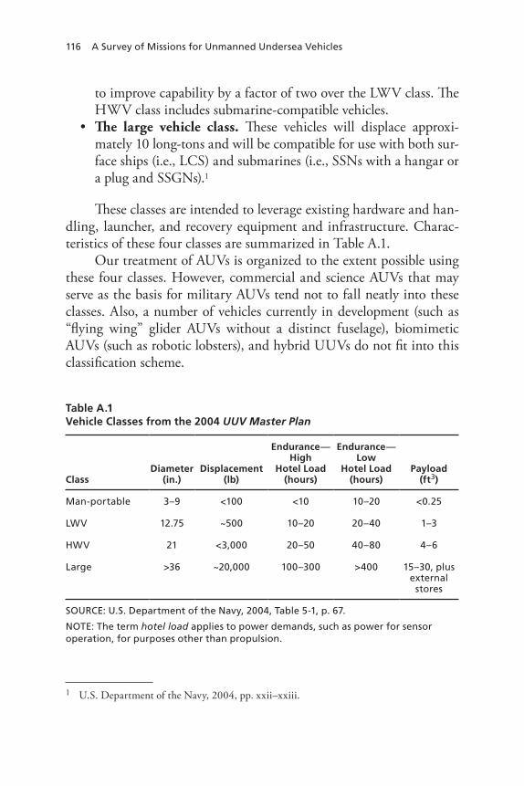
116 A Survey of Missions for Unmanned Undersea Vehicles
to improve capability by a factor of two over the LWV class. The HWV class includes submarine-compatible vehicles.The large vehicle class.• These vehicles will displace approxi-mately 10 long-tons and will be compatible for use with both sur-face ships (i.e., LCS) and submarines (i.e., SSNs with a hangar or a plug and SSGNs).1
These classes are intended to leverage existing hardware and han-dling, launcher, and recovery equipment and infrastructure. Charac-teristics of these four classes are summarized in Table A.1.
Our treatment of AUVs is organized to the extent possible using these four classes. However, commercial and science AUVs that may serve as the basis for military AUVs tend not to fall neatly into these classes. Also, a number of vehicles currently in development (such as “flying wing” glider AUVs without a distinct fuselage), biomimetic AUVs (such as robotic lobsters), and hybrid UUVs do not fit into this classification scheme.
1 U.S. Department of the Navy, 2004, pp. xxii–xxiii.
Table A.1Vehicle Classes from the 2004 UUV Master Plan
ClassDiameter
(in.)Displacement
(lb)
Endurance—High
Hotel Load(hours)
Endurance—Low
Hotel Load(hours)
Payload(ft3)
Man-portable 3–9 <100 <10 10–20 <0.25
LwV 12.75 ~500 10–20 20–40 1–3
hwV 21 <3,000 20–50 40–80 4–6
Large >36 ~20,000 100–300 >400 15–30, plus external
stores
SOUrCe: U.S. Department of the navy, 2004, table 5-1, p. 67.
nOte: the term hotel load applies to power demands, such as power for sensor operation, for purposes other than propulsion.

UUV Market Survey 117
Man-Portable AUVs
REMUS 100. Development of Remote Environmental Monitoring Units (REMUS) began with conceptual development in 1993, and the first REMUS vehicle was built in 1995. The original REMUS vehicle has evolved into the REMUS 100 (shown in Figure A.1). Today, there is a family of REMUS vehicles that are differentiated by depth designa-tors. For example, the REMUS 100 is depth rated to 100 m (328 ft); the REMUS 600 is depth rated to 600 m (1,969 ft). As of December 2007, 174 REMUS vehicles have been built.2 The U.S. Navy has pro-cured more than 40 REMUS AUVs of all types as of mid-2008.3 The REMUS 100 and the Hydroid-12 (described below) collectively repre-sent Surface Mine Countermeasure (SMCM) Increment 1.4
2 Author interview with Christopher von Alt, President of Hydroid, LLC., Hydroid Corpo-rate Headquarters, East Falmouth, Mass., December 2007.3 Jane’s Information Group, Ltd., 2008.4 Office of the Secretary of Defense, 2007b, p. 152.
Figure A.1REMUS 100
RAND MG808-A.1
SOURCE: Photo courtesy of Hydroid, Inc.
CTD sensor
Acoustic doppler current profiler/doppler velocity log
Chemical lightbracket
GPS/iridium/WiFi antenna
Navigation sonar
Side-scansonar array
Magneticon/off switch
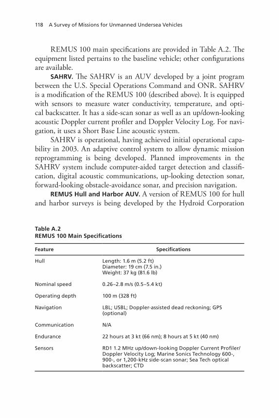
118 A Survey of Missions for Unmanned Undersea Vehicles
REMUS 100 main specifications are provided in Table A.2. The equipment listed pertains to the baseline vehicle; other configurations are available.
SAHRV. The SAHRV is an AUV developed by a joint program between the U.S. Special Operations Command and ONR. SAHRV is a modification of the REMUS 100 (described above). It is equipped with sensors to measure water conductivity, temperature, and opti-cal backscatter. It has a side-scan sonar as well as an up/down-looking acoustic Doppler current profiler and Doppler Velocity Log. For navi-gation, it uses a Short Base Line acoustic system.
SAHRV is operational, having achieved initial operational capa-bility in 2003. An adaptive control system to allow dynamic mission reprogramming is being developed. Planned improvements in the SAHRV system include computer-aided target detection and classifi-cation, digital acoustic communications, up-looking detection sonar, forward-looking obstacle-avoidance sonar, and precision navigation.
REMUS Hull and Harbor AUV. A version of REMUS 100 for hull and harbor surveys is being developed by the Hydroid Corporation
Table A.2REMUS 100 Main Specifications
Feature Specifications
hull Length: 1.6 m (5.2 ft)Diameter: 19 cm (7.5 in.)weight: 37 kg (81.6 lb)
nominal speed 0.26–2.8 m/s (0.5–5.4 kt)
Operating depth 100 m (328 ft)
navigation LBL; USBL; Doppler-assisted dead reckoning; GpS (optional)
Communication n/A
endurance 22 hours at 3 kt (66 nm); 8 hours at 5 kt (40 nm)
Sensors rD1 1.2 Mhz up/down-looking Doppler Current profiler/Doppler Velocity Log; Marine Sonics technology 600-, 900-, or 1,200-khz side-scan sonar; Sea tech optical backscatter; CtD

UUV Market Survey 119
and by the Woods Hole Oceanographic Institute. Beyond homeland security, it has clear relevance to the battlespace-preparation mission.
Bluefin-9 AUV. Bluefin Robotics is a spin-off of the Massachusetts Institute of Technology (MIT) Autonomous Underwater Vehicle Lab-oratory, which has developed a range of deep-diving AUVs (from Sea-Squirt to Bluefin). Bluefin UUVs are based on technology developed by the MIT AUV laboratory and the Monterey Bay Aquarium Research Institution, whose design efforts aimed to adopt off-the-shelf technolo-gies and exploit the advantages of small vehicles. The result is a family of AUVs, the smallest of which is the Bluefin-9, also known as Sealion (Figure A.2). The Bluefin-9 was designed for bottom mapping in shal-low water. Its modular design features standalone, pressure-tolerant bat-tery and data modules that can be exchanged for fresh units through a hatch without opening pressure vessels. Bluefin AUVs use gimballed, ducted propulsors. Such propulsors simplify the design by eliminating control surfaces and their actuators and are thought to reduce fouling. Bluefin-9 main specifications are provided in Table A.3.
Figure A.2Bluefin-9
RAND MG808-A.2
SOURCE: Photo courtesy of Bluefin Robotics Corporation.

120 A Survey of Missions for Unmanned Undersea Vehicles
Flying Plug. The now-discontinued Flying Plug program was intended to provide attack submarines with the means to plug into undersea fiber-optic networks. A Flying Plug was to be launched in the vicinity of a fixed undersea data node. Like the LMRS, the Flying Plug concept called for launching an AUV from a torpedo tube with fiber-optic cable spooling out from both the AUV and the host subma-rine. With the AUV plugged into an undersea network, the submarine would either gain enhanced situational awareness or be better able to communicate with the outside world. The submarine would remain fully connected during data transfer but not be required to loiter near the underwater node. Due to the difficulty of recovering AUVs through submarine torpedo tubes, the Flying Plug was to be scuttled at the end of a mission.
Naval Research and Development (NRaD), a predecessor to the Space and Naval Warfare Systems Center, San Diego, developed a test-bed Flying Plug (Figure A.3). This prototype AUV demonstrated an autonomous capability to acoustically locate data nodes and optically
Table A.3Bluefin-9 Main Specifications
Feature Specifications
hull Length: 1.65 m (5.4 ft)Diameter: 240 mm (9 in.)weight in air: 50 kg (110 lb)weight in water: −2 kg (−4 lb)
Speed 1.0–2.6 m/s (2–5 kt)
Operating depth 100 m (328 ft)
endurance 12 hours at 2 kt
Communications Acoustic and radio-frequency modems
Sensors 900 khz side-scan sonar;a CtD; optical backscatter turbidity sensorb
SOUrCe: Jane’s Information Group, Ltd., 2008.a Alternatively, the vehicle can be equipped with a 900/1,800 khz dual-frequency side-scan sonar with a resolution of approximately 2 in. and ranges of 50 m per side.b A low-light video camera is also available as a sensor.

UUV Market Survey 121
dock with them.5 Testing in San Diego Bay in FY96 demonstrated a docking ability limited by water depth, biological noise, and turbidity (with an optical range of less than 10 m). Significantly better docking performance was projected under more-favorable conditions. Flying Plug main specifications are provided in Table A.4.
EMATT. The MK-39 Mod 2 EMATT can be deployed from ASW aircraft and from surface ships. Once deployed, the EMATT operates at speeds of 3 kt (with 10-hour endurance) to 8 kt (with 4-hour endur-ance) and changes heading (with realistic turn rates) autonomously or in response to active sonar ensonification. The EMATT projects broad-band and narrowband noise signatures representative of a modern threat submarine, and it can simulate submarines’ transient noise.6 The
5 A similar capability was demonstrated by another NRaD AUV, Odyssey. 6 Submarine transient noise results from events such as control surface movement, start-ing and stopping machinery, and opening torpedo tube doors. Transient noise can last from
Figure A.3Flying Plug
RAND MG808-A.3
SOURCE: Steve Cowen, Flying Plug: A Small UUV Designed for Submarine Connectivity, NCCOSC D746, Advanced Concepts Branch, Naval Command, Control and Ocean Surveillance Center, 1997.

122 A Survey of Missions for Unmanned Undersea Vehicles
MK-39 Mod 2 EMATT also has an echo repeater for all fleet active-sonar sensors, including torpedoes. It can be set to create a pulsed mag-netic field for training with magnetic anomaly-detection systems. The EMATT is also equipped with a range pinger so that it can be tracked on calibrated ranges.
EMATT weighs 10.1 kg (22.3 lb), is 12.4 cm (4.9 inches) in diam-eter, and is 91.4 cm (36 inches) long. EMATT is produced by Lock-heed Martin’s Sippican Underwater Vehicles Division. The unit cost of EMATT in FY07 was $3,080.7
Light-Weight Vehicles
Bluefin-12. The Bluefin-12 reflects much of the design philosophy that informed development of the Bluefine-9. Both are modular designs with a free-flooding architecture, and both use pressure-tolerant batter-ies and data modules that can be exchanged without opening pressure vessels. Bluefin-12 main specifications are provided in Table A.5.
a few milliseconds to several seconds. Because such noises are characteristic of submarines, they can be used to classify as well as detect them.7 U.S. Department of the Navy, Fiscal Year (FY) 2007 Budget Submission, Weapons Pro-curement, February 2006, p. 88.
Table A.4Flying Plug Main Specifications
Feature Specifications
hull Length: 127 cm (50 in.)Diameter: 22.9 cm (9 in.)
Operating depth 305 m (1,000 ft)
Communication Acoustic low-level command link
Maximum speed 1.8 m/s (3.5 kt)
range 1.4 km (4,500 ft); limited by the length of its onboard fiber-optic cable
Sensors 170 khz sonar; optical quadrant detector systema
SOUrCe: Jane’s Information Group, Ltd., 2008.a the optical quadrant detector was a nonimaging optical system that has been compared to the homing sensor on the Sidewinder air-to-air missile.

UUV Market Survey 123
SMCM UUV Increment 2. The SMCM UUV Increment 2 is a modification of the Bluefin-12 AUV. Modifications include a larger (1 terabyte) removable data-storage module, an integrated Kearfott INS system, a military GPS system, system hardening to meet information assurance guidelines, and the design and integration of a forward fin module to minimize crab angle in high-current environments. Three user-operational evaluation systems (with two vehicles per system) have been procured for SMCM program risk mitigation and to study tactics, ship integration, and human-system interfaces. SMCM UUV Increment 2 main specifications are provided in Table A.6.
The dual-frequency SAS on the SMCM UUV Increment 2 vehi-cle is intended to enable the detection of buried mines and the identifi-cation of proud mines8 using high-resolution imagery. This system will also provide high-resolution images at greater ranges than are achiev-able with the SMCM UUV Increment 2 sonars. The performance of this system will be tested with the SMCM UUV Increment 2 vehicles, which are scheduled to be retired in FY11.9
8 Mines that sit on the bottom.9 Office of the Secretary of Defense, 2007b, p. 153.
Table A.5Bluefin-12 Main Specifications
Feature Specifications
hull Length: 2.1–3.8 m (84–150 in.), depending on payloadDiameter: 324 mm (12.75 in.)weight in air: 50 kg (300–500 lb), depending on payloadweight in water −2 kg (−4 lb)
Speed 0.26–2.6 m/s (0.5–5.0 kt)
Operating depth 200 m (656 ft)
endurance 10–23 hours, depending on speed
Communications Acoustic and radio-frequency modems; Iridium satellite
Sensors Side-scan sonar; SAS; buried-object search sonar; forward-looking sonar; CtD (all optional)
SOUrCe: Jane’s Information Group, Ltd., 2008.

124 A Survey of Missions for Unmanned Undersea Vehicles
REMUS 600. The REMUS 600 AUV was developed at the Woods Hole Oceanographic Institute through funding from ONR.10 It was designed to support the Navy’s need for AUVs with endurance, pay-load capacity, and operating depth beyond those of the REMUS 100. Vehicle size and power supply for payloads were increased for greater payload capacity. Greater payload capacity was also achieved by adopt-ing a modular design to better accommodate user-configured pay-loads.11 The modular design of the REMUS 600 uses screw-together hull sections that can be separated for vehicle reconfiguration, mainte-nance, or shipping.
The first REMUS 600 was developed at the Woods Hole Ocean-ographic Institute in 2003. Two more REMUS 600 vehicles have been built since then, and Hydroid, LLC, is preparing to build additional vehicles.12 The REMUS 600 features a Small Synthetic Aperture Mine-hunter (SSAM) side-looking sonar complemented by independently
10 Note that the REMUS 600 is also called the REMUS 12.75 (because its diameter is 12.75 inches).11 Modularity is also a feature of other recent AUV designs. 12 Woods Hole Oceanographic Institution, “Oceanographic Systems Laboratory, Autono-mous Underwater Vehicle, REMUS,” Web page, last updated November 19, 2008.
Table A.6SMCM UUV Increment 2 Main Specifications
Feature Specifications
hull Length: 3.4 m (11 ft)Diameter: 32.4 cm (12.75 in.)weight in air: 249 kg (550 lb)
Operating depth 67 m (220 ft)
Communication Acoustic low-level command link
Maximum speed 2.6 m/s (5 kt)
endurance 12 hours at a 3-kt loiter speed
Sensors Dual-frequency SAS; CtD; transmisso-meter; current profiler
SOUrCe: Office of the Secretary of Defense, 2007b, p. 153.
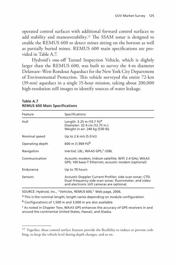
UUV Market Survey 125
operated control surfaces with additional forward control surfaces to add stability and maneuverability.13 The SSAM sonar is designed to enable the REMUS 600 to detect mines sitting on the bottom as well as partially buried mines. REMUS 600 main specifications are pro-vided in Table A.7.
Hydroid’s one-off Tunnel Inspection Vehicle, which is slightly larger than the REMUS 600, was built to survey the 4-m diameter Delaware–West Rondout Aqueduct for the New York City Department of Environmental Protection. This vehicle surveyed the entire 72-km (39-nm) aqueduct in a single 15-hour mission, taking about 200,000 high-resolution still images to identify sources of water leakage.
13 Together, these control surface features provide the flexibility to induce or prevent crab-bing, to keep the vehicle level during depth changes, and so on.
Table A.7REMUS 600 Main Specifications
Feature Specifications
hull Length: 3.25 m (10.7 ft)a
Diameter: 32.4 cm (12.75 in.)weight in air: 240 kg (530 lb)
nominal speed Up to 2.6 m/s (5.0 kt)
Operating depth 600 m (1,969 ft)b
navigation Inertial; LBL; wAAS GpS,c USBL
Communication Acoustic modem; Iridium satellite; wiFi 2.4 Ghz; wAAS GpS; 100 base-t ethernet; acoustic modem (optional)
endurance Up to 70 hours
Sensors Acoustic Doppler Current profiler; side-scan sonar; CtD. Dual-frequency side-scan sonar, fluorometer, and video and electronic still cameras are optional.
SOUrCe: hydroid, Inc., “Vehicles, reMUS 600,” web page, 2006.a this is the nominal length; length varies depending on module configuration.b Configurations of 1,500 m and 3,000 m are also available.c As noted in Chapter two, wAAS GpS enhances the accuracy of GpS receivers in and around the continental United States, hawaii, and Alaska.

126 A Survey of Missions for Unmanned Undersea Vehicles
The UK Ministry of Defense is procuring two REMUS 600 systems complete with operating, deployment, recovery, and sup-port equipment for the Royal Navy at a total cost of approximately $11.1 million.14
REMUS 3000. The REMUS 3000 is a developmental vehicle simi-lar to the REMUS 600 but constructed of titanium. It will have a more-advanced system for underwater mapping and imaging. Main specifications for the REMUS 3000 are provided in Table A.8.
REMUS 6000. The REMUS 6000 (Figure A.4) was designed through ONR funding to extend endurance and increase payload and operating depth. The first REMUS 6000 was the Subsurface Auton-omous Mapping System vehicle, which was procured by the Naval Oceanographic Office in 2001 for deep-sea operations. REMUS 6000 main specifications are provided in Table A.9.
14 Defense Industry Daily, “2 REMUS 600 Systems for UK Royal Navy,” Web page, Sep-tember 23, 2007.
Table A.8REMUS 3000 Main Specifications
Feature Specifications
hull Length: 3.7 m (12.2 ft)Diameter: 35.6 cm (14 in.)weight in air: 345 kg (760 lb)
nominal speed 1.5–2.0 m/s (2.9–3.9 kt)
Operating depth 3,000 m (9,843 ft)
endurance 49–77 hours at 3 kt (147–231 nm); 33–44 hours at 4 kt (132–176 nm), depending on the equipment in use
navigation InS; GpS; LBL acoustic navigation
Sensors Acoustic Doppler Current profiler; pencil-beam forward-looking sonars; optical backscattering sensors; CtD
SOUrCe: woods hole Oceanographic Institution, 2008.

UUV Market Survey 127
Figure A.4REMUS 6000 Components
RAND MG808-A.4
SOURCE: Image courtesy of Hydroid, Inc.
Electronics and lithium-ion battery packs
Sub-bottom profiler or electronic stills camera
Side-scan sonar Camerastrobe light
Syntacticfoamblock
Acoustic doppler current profiler/ inertial navigation unit
GPD/iridium/WiFi antenna for communication when at the surface
Strobe recovery lightConductivity,
temperature, anddepth sensor
Upper LBL fornavigation
Acoustic modemtransducer
Pitch and yawactuators and fins
Lower LBL fornavigation
Propeller, giving theAUV a speedof up to ~5 kt
Lifting point
Nose withrelease andrecoverysystem
Recovery float
Table A.9REMUS 6000 Main Specifications
Feature Specifications
hull Length: 3.84 m (12.6 ft)Diameter: 71 cm (28 in.)weight in air: 862 kg (1,900 lb)
Speed Up to 2.6 m/s (5.1 kt)
Operating depth 6,000 m (19,685 ft)a
navigation Inertial; LBL; USBL
Communication Acoustic modem; Iridium; wiFi 2.4 Ghz
endurance 22 hours (nominal)
Sensors Acoustic Doppler Current profiler; side-scan sonar; CtD. Dual-frequency side-scan sonar, fluorometer, video camera, electronic still camera with 200 watt-second strobe lighting, and sub-bottom profiler are optional.
SOUrCe: hydroid, Inc., 2006.a A 4,000-m configuration is available.

128 A Survey of Missions for Unmanned Undersea Vehicles
Heavy-Weight Vehicles
NMRS. NMRS is a mine-hunting UUV system launched and recovered from an SSN-688–class submarine. The system is capable of mine detection, classification, and localization. It consists of two reusable UUVs; launch and recovery equipment (including a winch and drogues); and shipboard control, processing, and monitoring equipment. NMRS UUVs normally operate as ROVs controlled via fiber-optic cables from their launch submarine. If a fiber-optic cable breaks during the mission, NMRS UUVs are programmed to return to their launch locations for recovery.
NMRS UUVs have a diameter of 21 inches and are slightly shorter than a MK-48 torpedo.15 They are launched and recovered from stan-dard SSN-688–class submarine torpedo tubes. The UUVs are loaded backward (propulsor first) into torpedo tubes; when launched, they back out of the torpedo tube under their own power but remain tethered to the launch submarine by a steel cable and drogue assembly. They are then towed to the mission area by the launch submarine. At the mission area, an NMRS UUV releases itself from the drogue and an armored fiber-optic cable begins to pay out from both the drogue and the UUV. When the mission is completed, the UUV docks with the drogue (much like a midair refueling) and is reeled back into the torpedo tube.
During a mission, the NMRS UUV scans for mine-like objects using a multibeam high-frequency active sonar and performs object clas-sification with side-scan sonars. The UUV continuously reports its status, position, and sonar data to the host submarine via the fiber-optic tether.
NMRS was developed as an advanced concept technology devel-opment (ACTD) program, and the program was terminated in FY00. At that time, two deficiencies were recognized:
Poor navigation accuracy.• The limited accuracy of the NMRS navigation system reduced its value for mine avoidance or dis-posal. The host submarine could not always determine the loca-tion of identified mines with accuracy sufficient to avoid them or relocate them for disposal.
15 The MK-48 ADCAP torpedo is 53 mm (21 inches) in diameter and 6.1 m (20 ft) long.

UUV Market Survey 129
high false-alarm rate.• A high false-alarm rate can create the illusion of a mine threat when none exists. It can also complicate the problem of mine avoidance when nonthreatening mine-like objects must also be avoided.
Three disadvantages of the NMRS CONOP were also recognized during ACTD termination. First, the high-demand/low-density nature of SSNs as host platforms limits the potential value of systems such as NMRS. Second, relative to autonomous operation, operation as an ROV using fiber-optic tethers limits UUV capability in large area search. Finally, NMRS is incapable of producing desired bathymetric data.
One operational prototype NMRS system was built and made available to the Commander, Submarine Development Squadron Five, in FY99. When the NMRS program was terminated, attention and funding were turned to developing LMRS.
LMRS. The AN/BLQ-11 LMRS was intended to provide the fleet with a robust, long-term capability to conduct the type of clandestine minefield reconnaissance desired under the 1994 UUV Program Plan. A quantity of 6–12 systems was planned, and procurement was set to begin in FY04. The systems were intended to operate from Virginia-class SSNs and from Ohio-class SSGNs. As described below, however, the program was halted after an OSD-level review.
Like NMRS, LMRS was intended to be launched from a sub-marine torpedo tube. It could be fitted with a lithium battery or a silver-zinc battery. As a fully autonomous vehicle, the LMRS improved on the NMRS in terms of improved sensor, energy, and signal pro-cessing capability (for an enhanced search rate and larger search areas of 460–650 nm2).16 It was to have located mines with an accuracy of 71 m (233 ft) without detonating them.17 LMRS AUV main specifica-tions are shown in Table A.10.
16 Albert Konetzni, “Mine Warfare,” CHIPS—The Department of the Navy Information Technology Magazine, Winter 2003.17 More precisely, the specification was for a 71-m circular error probable in locating mine-like objects. This means that in 50 percent of the cases, the location error was to be less than 71 m.

130 A Survey of Missions for Unmanned Undersea Vehicles
The CONOP for LMRS called for a modular system that was to be airlifted and installed in a submarine’s torpedo room. The system was intended to take up no more space than 10 torpedoes. Each sub-marine was to carry two UUVs and five interchangeable battery packs. LMRS AUVs were to have been recovered using a telescoping robotic arm located on a torpedo tube. The AUV was intended to overtake the SSN and be grabbed by the arm in passing. The arm would then have pivoted the AUV and inserted it into the torpedo tube. Finally, the AUV would have been attached from the torpedo room and pulled into the submarine. Engineering challenges seen at the time included meeting mission reliability goals, achieving reliable launch and recovery, meet-ing reduced radiated-noise goals, certifying an advanced high-density primary battery for submarine use, and developing effective computer-aided detection and classification algorithms. LMRS navigation accu-racy was also viewed as a potential issue for contact re acquisition and identification and mine neutralization. AUV volume was also consid-
Table A.10LMRS Main Specifications
Feature Specifications
hull Length: 6.1 m (240 in.)Diameter: 0.53 m (21 in.)weight in air: ~1,270 kg (~2,800 lb)
Speed range 2.1–3.6 m/s (4–7 kt)
Operating depth 12–450 m (39.4–1,476.0 ft)
endurance At least 40 hours; 75 nm (threshold) to 120 nm (objective)
Sensors Sonatech forward-looking search and obstacle avoidance sonar; side-scan sonar for object classification and docking
Communications Acoustic and radio frequency using submarine communication links
navigation InS
SOUrCeS: Jane’s Information Group, Ltd., 2008; Medeiros, 2007; national research Council, Autonomous Vehicles in Support of Naval Operations, washington, D.C.: the national Academies press, 2005, p. 126.
nOte: endurance reflects design threshold and objective.
UUV Market Survey 131
ered problematic, since some thought that LMRS would benefit from increased volume and payload, in which case it might have needed to be housed in a DDS. The LMRS had an endurance of 12–14 hours when equipped with a silver-zinc battery and an endurance of 40–48 hours at 4 kt when equipped with a lithium battery. This would have resulted in a range of 70–75 nm, giving the vehicle a search area of 35–50 nm2 per sortie. Up to six sorties per day per vehicle might have been possible.
The LMRS CONOP called for launching the AUV near the mis-sion area. Sensor data were to be partially processed aboard the AUV and then recorded. The AUV would have transmitted highlights to the host submarine via acoustic or satellite communication. The vehicle was also to have been capable of transmitting data to the fleet.
LMRS was developed by the Boeing Corporation. It was due to achieve initial operational capability by December 2004, but it became apparent before that time that the LMRS project was well behind schedule and over budget. This triggered an OSD-level review, and the LMRS program was halted. At that time, a single LMRS system had been built. The LMRS first demonstrated the ability to rendezvous and dock with an SSN in January 2006.
A follow-on program to the LMRS—the Multi-Reconfigurable Unmanned Undersea Vehicle (MRUUV)—was begun.18 The MRUUV was intended to expand the capabilities of the LMRS through its inclu-sion of ISR sensors and ASW capabilities. Like the LMRS, it was to be a 20-ft long, 21-inch vehicle weighing about 2,800 lb. The MRUUV was to be modular, which would have enabled it to change missions by switching payload modules. In May 2003, the Navy awarded a design contract for the MRUUV to Lockheed Martin. The contract called for Lockheed Martin to include a module for mine identification. The MRUUV program has subsequently transitioned to the MRUUVS, which uses the Advanced Development UUV (ADUUV) for risk reduction.
ADUUV. During transition from the MRUUV program to the MRUUVS, designers used the ADUUV as a risk-reduction prototype. Like the existing LMRS and the planned MRUUVS, the ADUUV can
18 National Research Council, 2005, p. 127.

132 A Survey of Missions for Unmanned Undersea Vehicles
be launched and recovered through submarine torpedo tubes. Also like the MRUUVS, the ADUUV can accommodate interchangeable mod-ular payloads that can be swapped out for various missions. The payload modules for the ADUUV, like those of the MRUUVS, are to be used for clandestine ISR, mine reconnaissance, and tactical ocean surveys. The ADUUV and the MRUUVS use the same energy-section interface control document and the same payload and vehicle specifications.
Both the ADUUV and the MRUUVS can be launched and recov-ered from SSN torpedo tubes and can accommodate interchangeable modular payloads for MCM and ISR. They share payload and vehi-cle specifications and have propulsion motors of 2–3 hp. The clearest distinctions between the ADUUV and the MRUUVS appear in their sensor and endurance requirements.19 The MRUUVS was designed to use the L-PUMA forward-looking sonar in place of the more limited sonar used by the ADUUV. The endurance of the MRUUVS is stated to be 10–20 hours on renewable batteries and 40–50 hours on primary batteries. The ADUUV is only required to have at least two hours of endurance. However, Lockheed Martin has installed the L-PUMA on the ADUUV, so the sensor distinction between the MRUUVS and the ADUUV has been erased. It is also noteworthy that the LMRS satisfied the MRUUVS’s threshold requirements for speed and endurance, prov-ing an endurance of 13 hours when equipped with a silver-zinc battery and more than 40 hours when equipped with a lithium battery.20
ADUUV development was recently suspended before its capabil-ity for modular payloads was demonstrated.21
MRUUVS. The MRUUVS, introduced above, will be a 21-inch UUV that is hosted by Los Angeles– and Virginia-class SSNs. Like NMRS, LMRS, and the ADUUV, the MRUUVS will be designed for launch and recovery from torpedo tubes. In the future, it may be hosted by LCSs and SSGNs.22 The MRUUVS will have modular pay-
19 Office of the Secretary of Defense, 2007b, pp. 148, 152.20 Office of the Secretary of Defense, 2007b, p. 147.21 Paul Siegrest, “Unmanned Maritime Vehicle Systems Update,” briefing presented at the AUVSI Unmanned System Program Review 2008, PMS 403, February 28, 2008.22 Office of the Secretary of Defense, 2007b, p. 148.

UUV Market Survey 133
loads that enable it to perform ISR and MCM missions in denied areas. The ISR payload will be designed for IMINT and SIGINT data collection. The MCM capability will employ a bottom-looking syn-thetic aperture array and include bottom and volume contact detec-tion, classification, and localization using the L-PUMA. The MCM module will be developed first. Some of the planned characteristics of the MRUUVS are shown Table A.11.
Department of the Navy budget material describes planned devel-opment of the MRUUVS beginning in FY09 as follows:
The MRUUVS will leverage technology developed under two pre-vious programs: the AN/BLQ-11 Long-Term Mine Reconnaissance System (LMRS) and the Littoral Precision Underwater Mapping Array (LPUMA). To mitigate remaining risk before MS-B [Mile-stone B], the program will conduct component development and capability demonstration utilizing the LMRS to mature homing and docking methods for attack submarines (SSNs). LPUMA will
Table A.11Planned MRUUVS Characteristics
Feature Specifications
hull Length: 6.1 m (240 in.)Diameter: 0.53 m (21 in.)weight in air: ~1,361 kg (3,000 lb)
Speed range 0.0–4.1 m/s (0–8 kt)
Operating depth At least 12.2 m (40 ft)
endurance 40–50 hours (primary battery); 10–20 hours (renewable battery)
Sensors Bottom-looking SAS with volume-search capability; forward-looking L-pUMA sonar
Communications Acoustic and radio frequency using submarine communication links
navigation InS with Doppler Velocity Log
SOUrCe: Office of the Secretary of Defense, 2007b, p. 148.
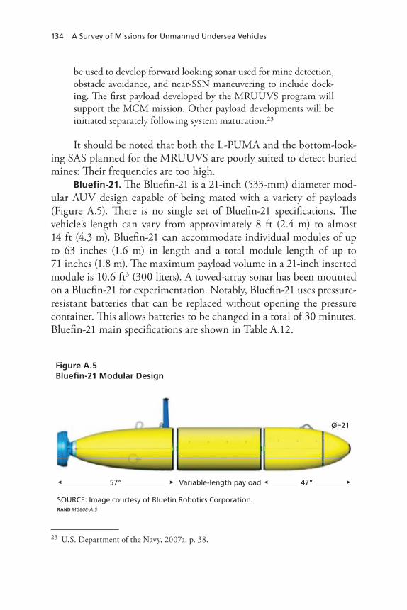
134 A Survey of Missions for Unmanned Undersea Vehicles
be used to develop forward looking sonar used for mine detection, obstacle avoidance, and near-SSN maneuvering to include dock-ing. The first payload developed by the MRUUVS program will support the MCM mission. Other payload developments will be initiated separately following system maturation.23
It should be noted that both the L-PUMA and the bottom-look-ing SAS planned for the MRUUVS are poorly suited to detect buried mines: Their frequencies are too high.
Bluefin-21. The Bluefin-21 is a 21-inch (533-mm) diameter mod-ular AUV design capable of being mated with a variety of payloads (Figure A.5). There is no single set of Bluefin-21 specifications. The vehicle’s length can vary from approximately 8 ft (2.4 m) to almost 14 ft (4.3 m). Bluefin-21 can accommodate individual modules of up to 63 inches (1.6 m) in length and a total module length of up to 71 inches (1.8 m). The maximum payload volume in a 21-inch inserted module is 10.6 ft3 (300 liters). A towed-array sonar has been mounted on a Bluefin-21 for experimentation. Notably, Bluefin-21 uses pressure-resistant batteries that can be replaced without opening the pressure container. This allows batteries to be changed in a total of 30 minutes. Bluefin-21 main specifications are shown in Table A.12.
23 U.S. Department of the Navy, 2007a, p. 38.
Figure A.5Bluefin-21 Modular Design
RAND MG808-A.5
SOURCE: Image courtesy of Bluefin Robotics Corporation.
Variable-length payload 47”57”
O=21

UUV Market Survey 135
Bluefin-21 BPAUV. The Bluefin-21 BPAUV (Figure A.6) was developed by Bluefin Robotics to meet the Navy’s requirements for clandestine ISR and survey.24 ONR received two Bluefin-21 BPAUVs on loan from Bluefin Robotics circa 2001. In 2005, Bluefin Robotics was given a $6.5-million design and development contract from the Naval Sea Systems Command for delivery of a Bluefin-21 BPAUV mis-sion module for the Navy’s LCS Flight 0. The mission module will con-tain two Bluefin-21 BPAUVs. In this context, the Bluefin-21 BPAUV will map the sea floor and gather other oceanographic data to support the LCS mine-warfare mission package.25 Work under this contract was to be completed shortly before the end of FY08.26
24 The Bluefin-21 is the base vehicle for the Bluefin-21 BPAUV; these AUVs have distinct characteristics.25 Jane’s Information Group, Ltd., 2008; Mike Alperi, “Navy Unmanned Maritime Sys-tems,” PMS 403 briefing, Washington, D.C., April 2007.26 U.S. Department of the Navy, Fiscal Year (FY) 2009 Budget Estimates: Other Procurement, Activities 5–7, February 2008, p. 95.
Table A.12Bluefin-21 Main Specifications
Feature Specifications
hull Length: 2.4–4.2 m (94–165 in.)Diameter: 0.53 m (21 in.)Base vehicle weight in air: 180 kg (397 lb)
nominal speed 0.5–2.6 m/s (1–5 kt)
Operating depth 200–4,500 m (656–14,764 ft)
endurance Up to 20 hours at 1.5 m/s (2.9 kt); 60 nm with a standard payload
Sensors 455-khz side-scan sonar; CtD
Communications radio frequency: 900 Mhz up to 128 kbps LOS over 1–2 nm; Iridium high-rate (2,400 bps) data in burst mode
navigation InS or Altitude heading reference System; Doppler Velocity Log; GpS; USBL; LBL
SOUrCe: Jane’s Information Group, Ltd., 2008.
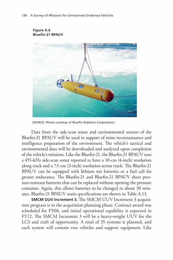
136 A Survey of Missions for Unmanned Undersea Vehicles
Data from the side-scan sonar and environmental sensors of the Bluefin-21 BPAUV will be used in support of mine reconnaissance and intelligence preparation of the environment. The vehicle’s tactical and environmental data will be downloaded and analyzed upon completion of the vehicle’s missions. Like the Bluefin-21, the Bluefin-21 BPAUV uses a 455-kHz side-scan sonar reported to have a 10-cm (4-inch) resolution along track and a 7.5-cm (3-inch) resolution across track. The Bluefin-21 BPAUV can be equipped with lithium ion batteries or a fuel cell for greater endurance. The Bluefin-21 and Bluefin-21 BPAUV share pres-sure-resistant batteries that can be replaced without opening the pressure container. Again, this allows batteries to be changed in about 30 min-utes. Bluefin-21 BPAUV main specifications are shown in Table A.13.
SMCM UUV Increment 3. The SMCM UUV Increment 3 acquisi-tion program is in the acquisition planning phase. Contract award was scheduled for FY08, and initial operational capability is expected in FY12. The SMCM Increment 3 will be a heavy-weight UUV for the LCS and craft of opportunity. A total of 35 systems is planned, and each system will contain two vehicles and support equipment. Like
Figure A.6Bluefin-21 BPAUV
RAND MG808-A.6
SOURCE: Photo courtesy of Bluefin Robotics Corporation.

UUV Market Survey 137
the SMCM UUV Increment 2, Increment 3 will be equipped with a relatively low-frequency broadband sonar able to penetrate the bottom in order to detect and classify buried and proud mines with high prob-ability and low false-alarm rates.27 SMCM UUV Increment 3 main specifications are shown in Table A.14.
HUGIN 3000. The HUGIN project was started in 1995 as a coop-erative effort among the Norwegian petroleum company Statoil, the Norwegian Defence Research Establishment, Norsk Undervannsinter-vensjon, and Kongsberg Maritime. Kongsberg Maritime now leads the
27 Mines that are completely buried in sandy ocean sediments are considered to be undetect-able by sonars operating at frequencies on the order of hundreds of kHz. At such frequencies, little acoustic energy penetrates the bottom; with sound velocities in bottom material exceed-ing sound velocity in water, total reflection occurs at shallow grazing angles. Export mines, such as the Italian Manta, exploit this phenomenon by using a case geometry that enables them to bury themselves once deployed. (A Manta mine damaged the hull of the USS Princ-eton [CG-59] during the Persian Gulf War.) Significantly improved penetration performance has been demonstrated using sonars operating in the regime of 2–16 kHz. Moreover, sound at these frequencies interacts with elastic targets, such as buried mines. See Maguer et al., 1999; Paul Siegrest, “Unmanned Maritime Vehicle Systems Update,” briefing presented at the AUVSI Unmanned System Program Review 2008, PMS 403, February 28, 2008, slide 13; Office of the Secretary of Defense, 2007b.
Table A.13Bluefin-21 BPAUV Main Specifications
Feature Specifications
hull Length: 3.3 m (128 in.)Diameter: 0.53 m (21 in.)weight in air: 363 kg (800 lb)
nominal speed 1.5–2.6 m/s (3–5 kt)
Operating depth 201 m (660 ft)
endurance 40 nm with rechargeable lithium ion batteries; 400 nm with fuel cell
Sensors 455-khz side-scan sonar; CtD
Communications radio frequency: 900 Mhz up to 128 kbps LOS over 1–2 nm; Iridium high-rate (2,400 bps) data in burst mode
navigation InS or Altitude heading reference System; Doppler Velocity Log; GpS; USBL; LBL
SOUrCe: Jane’s Information Group, Ltd., 2008.

138 A Survey of Missions for Unmanned Undersea Vehicles
project. Three models of HUGIN AUVs, differentiated by depth capa-bility, are now available. The HUGIN 1000 is depth rated to 1,000 m (3,281 ft), the HUGIN 3000 is depth rated to 3,000 m (9,843 ft), and the HUGIN 4500 is depth rated to 4,500 m (14,764 ft). All HUGIN AUVs are equipped with acoustic communication links to control the vehicle and provide real-time data connectivity. By weight, each of these models is classified as an HWV. However, each has a diameter of 1 m (39.4 inches), greater than the 21-inch diameter prescribed for HWVs by the UUV Master Plan.
HUGIN AUVs were first developed for commercial missions but are now being proposed for the following military missions:
MCM•rapid environmental assessment and battlespace access•ASW•ISR.• 28
28 Kongsberg, “Autonomous Underwater Vehicles—HUGIN AUV’s,” Web page, 2009.
Table A.14SMCM UUV Increment 3 Main Specifications
Feature Specifications
hull Length: 5.2 m (18 ft)Diameter: 0.53 m (21 in.)weight in air: 363 kg (800 lb)
nominal speed 1.5–2.6 m/s (3–5 kt)
Operating depth 91 m (300 ft)
endurance >16 hours
Sensors Low-frequency broadband sonar; SAS; CtD; transmisso-meter;a current profiler; bottom sediment profiler
Communications Acoustic modem; wLAn;b Iridium satellite
navigation InS or Altitude heading reference System; Doppler Velocity Log; GpS; USBL; LBL
SOUrCe: Office of the Secretary of Defense, 2007b.a transmissometers measure water clarity.b this is a wide area local network radio-frequency communication system.

UUV Market Survey 139
The HUGIN 3000 (shown in Figure A.7) is the oldest of the three HUGIN AUVs. It can operate with operator supervision or autono-mously. HUGIN 3000 main specifications are shown in Table A.15.
Figure A.7HUGIN 3000
RAND MG808-A.7
SOURCE: Photo courtesy of Kongsberg Maritime AS.
Table A.15HUGIN 3000 Main Specifications
Feature Specifications
hull Length: 5.35 m (17.6 ft)Diameter: 1 m (39.4 in.)weight in air: 1,400 kg (3,086 lb)
Operating depth 3,000 m (9,842 ft)
navigation LBL; USBL; Doppler-assisted dead reckoning; Kalman-filter assisted; GpS (optional)
Communication Acoustic control link; acoustic data link; acoustic emergency link; radio-frequency link; satellite communication system (optional)
nominal speed 2.1 m/s (4 kt)
endurance 50–60 hours, depending on speed and payload configuration
Sensors Multibeam echo sounder; subbottom profiler; side-scan sonar; CtD; volume-search sonar
SOUrCe: Kongsberg-Simrad, HUGIN 3000: An Autonomous Underwater Vehicle (AUV) for Accurate and Efficient Seabed Mapping, norway: Kongsberg Simrad A/S, 2006.

140 A Survey of Missions for Unmanned Undersea Vehicles
HUGIN 1000 Military Version. HUGIN began demonstrating the military capabilities of AUVs with the HUGIN I AUV in late 2001. Experience with the HUGIN I led HUGIN to develop a military ver-sion of the existing HUGIN 1000 AUV. Two military versions of the HUGIN 1000 AUVs have since been acquired by the Royal Norwe-gian Navy as part of a mine-reconnaissance system.
Both the baseline HUGIN 1000 and its military version use a common modular architecture (shown in Figure A.8). Both also use pressure-tolerant lithium polymer batteries and are capable of fully autonomous, mixed-initiative, and human-supervised operation.29 HUGIN 1000 Military Version main specifications are shown in Table A.16.
The multibeam echo sounder has a coverage rate of 0.4–0.8 km2/h (0.12–0.23 nm2/h) and resolves to squares 1 m or 2 m (3.3 ft or 6.6 ft) on a side. The standard SAS has a coverage rate of 0.5–2.0 km2/h
29 Documentation refers to the mixed-initiative mode of operation as semi-autonomous. In this mode, the military version of the HUGIN 1000 reports its status at regular intervals and may also receive simple instructions (Kongsberg Maritime, “Hugin 1000 System Descrip-tion, Military Version,” white paper, November 2003, p. 13).
Figure A.8A Typical HUGIN 1000 Configuration
RAND MG808-A.8
SOURCE: Image courtesy of Kongsberg Maritime AS.

UUV Market Survey 141
(0.15–0.58 nm2/h) and resolves to squares 10 cm (4 inches) on a side. The interferometric, high-resolution SAS is stated to have twice the coverage rate of the standard SAS, as well as twice the resolution. A conventional side-scan sonar for the HUGIN 1000 Military Version is stated to have a coverage rate of 0.3–0.5km2/h (0.12–0.19 nm2/h) with typical resolution of 25 × 25 cm (9.8 × 9.8 inches).30
When used for route surveys, the HUGIN 1000 Military Version collects high-resolution bathymetry data; high-resolution SAS imagery; information on automatically or manually detected bottom objects;
30 Kongsberg Maritime, 2003, pp. 6–7.
Table A.16HUGIN 1000 Military Version Main Specifications
Feature Specifications
hull Length: 3.85–5.0 m (12.6–16.4 ft)Diameter: 0.75 m (2.5 ft)weight in air: 600–850 kg (1,323–1,874 lb)
nominal speed 1 m/s (1.9 kt) minimum speed; 3 m/s (5.8 kt) maximum speed
Operating depth 1,000 m (3,281 ft)
endurance 7 hours at 2.1 m/s (4 kt) (with 200 w for payloads); 9 hours at 1.5 m/s (3 kt) (with 200 w for payloads)a
navigation hUGIn Doppler Velocity Log–aided InS; combined USBL and GpS; GpS/differential GpS; navp-Utp underwater transponder range/bearing navigation; terrain-referenced navigation; DpCA micronavigation
Communication On-deck ethernet; radio; acoustic command and data links; acoustic emergency link; wLAn; Iridium satellite
endurance 50–60 hours with a single battery, depending on speed and payload configuration
Sensors Multibeam echo sounder; SAS; interferometric SAS; dual-frequency 220/410 khz side-scan sonar; CtD
SOUrCe: Kongsberg Maritime, 2003, p. 43.a the hUGIn 1000 Military Version can be equipped with up to three batteries. endurance with two batteries is twice that shown above. endurance with three batteries is three times that shown above. Additional batteries reduce payload volume.

142 A Survey of Missions for Unmanned Undersea Vehicles
seabed classification (sand, mud, rock, etc.) information; information on sea currents (from operating depth to the bottom); and salinity, temperature, and sound-velocity measurements.
The HUGIN 1000 Military Vehicle is also designed to establish whether a forward area is mined and, if so, the extent of the mined area. To accomplish this, the vehicle transits to the potentially mined area, performs a planned survey, and returns to a predetermined recov-ery location. The vehicle can be set to surface periodically to refresh its navigation system for greater mapping accuracy. Otherwise, the stated mapping accuracy is 5–10 m.
Talisman. Talisman represents an initiative by the UK’s BAE Sys-tems to develop a family of UUVs for MCM, ISR, hydrography and meteorology, ASW, and support to SOF. Properly speaking, Talisman is comprised of underwater vehicles, a control system, remote consoles, communications modules, software, and support equipment. The Tal-isman program is fully funded by BAE Systems. Begun in 2004, the program entered initial trials in less than one year.
Three generations of Talisman vehicles have been constructed or are in construction. The original Talisman UUV is a proof-of-concept vehicle. It is approximately 4.5 m (14.8 ft) long and 2.5 m (8.2 ft) wide, and it weighs 1,800 kg (3,967 lb).31 It has a payload capacity of 500 kg (1,102 lb). The vehicle is constructed of a carbon-fiber composite and is faceted to reduce its target strength against active sonars. Electronic systems and payload are carried inside composite pressure vessels. Pro-pulsion uses six Seaeye Marine Limited vectorable thrusters that give Talisman a maximum speed of 5 kt and enable it to move vertically or hover, back down, and turn 360 degrees in its own length.
The second-generation Talisman vehicle, Talisman M, is opti-mized for autonomous MCM operations. BAE has stated that a design goal of the Talisman M was to reduce the vehicle’s dimensions and to reduce its weight to less than 1,000 kg (2,205 lb) while retaining a 500-kg (1,102-lb) payload capacity. Talisman M is, in a sense, a hybrid UUV-ROV. It is a UUV that operates ROVs in the form of Archerfish
31 Jane’s Information Group, Ltd., 2008.

UUV Market Survey 143
single-shot mine destructors.32 It can communicate with its host plat-form using WiFi or Iridium satellite communication, or acoustically. The operational concept for Talisman M begins with launch at a safe distance from an area of interest. The Talisman M then moves autono-mously to the area of interest and maps mine-like objects using a sil-ver-zincing sonar and a precision navigation system. The Talisman M then broaches and transmits the locations of detected mine-like objects to the host platform. An operator on the host platform selects mine-like objects of interest and directs Talisman M to launch Archerfish to investigate those objects. The Archerfish’s two midbody pivoting thrusters allow it to maneuver horizontally or hover while inspecting the target. Inspections can be acoustic or visual, the latter being con-ducted with the camera and lighting system on the Archerfish. A fiber-optic cable carries acoustic data and visual images back to Talisman M, which broadcasts them to an operator. A decision to destroy the object is therefore based on visual images from the Archerfish that are trans-mitted via the Talisman M. In principal, Talisman M can destroy up to four mines in a single sortie. In a series of platform trials in late 2005, a Talisman M UUV remotely launched an Archerfish that located a mine. This proved that all onboard sensors, from the still camera to the video camera, were functioning correctly.33
The third-generation Talisman vehicle, Talisman A, is optimized for ASW. BAE turned to Cosworth to develop and integrate a miniatur-ized 3-hp, two-stroke diesel engine for charging the Talisman A’s bat-teries while the vehicle is surfaced. Little more has been revealed about Talisman A, which until recently was a highly secretive program.
The Advanced Unmanned Search System. The Advanced Unmanned Search System (AUSS), shown in Figure A.9, is designed for
32 The BAE Systems Archerfish is a single-shot tool for clearing mines using a directed-energy warhead. Each Archerfish has a video camera with a light source. Twin propulsors enable Archerfish to move toward targets and to hover in their vicinity. Archerfish is wire-guided using a fiber-optic tether; the tether also passes imagery to the Talisman M, which in turn transmits images to the host platform. Archerfish has been selected for the U.S. Navy’s Airborne Mine Neutralization System and the Expendable Mine Neutralization System. The U.S. firm Nekton also builds a mine neutralization vehicle, Ranger. 33 Jane’s Information Group, Ltd., 2008.

144 A Survey of Missions for Unmanned Undersea Vehicles
largely autonomous ocean search at depths of up to 6.1 km (20,000 ft). Rather than communicating with AUSS on the surface or using a tether, operators communicate with AUSS using an acoustic data link for supervisory control. AUSS is capable of operating autonomously in such mission tasks as transiting to a given location, hovering, and executing preset sonar and optical search patterns. It has side-looking and forward-looking sonars and an electronic still camera.
AUSS was designed according to the philosophy that a mine search is not complete until operators see visual images of targets. AUSS dem-onstrated the ability to provide high-quality images in near–real time using an acoustic link. Figure A.10 shows a sample image transmitted acoustically from the AUSS. AUSS main specifications are provided in Table A.17.
Aqua Explorer 2000. The Aqua Explorer 2000 is an AUV designed to track undersea cables and monitor their depth. In doing so, the vehi-cle captures still-camera and continuous-video records of sea-bottom conditions and laid cables. It is also designed for bottom mapping.
Figure A.9AUSS
RAND MG808-A.9
SOURCE: Richard Ulrich and James Watson, Supervisory Control of Untethered Undersea Systems: A New Paradigm Verified, San Diego, Calif., 1995.

UUV Market Survey 145
Figure A.10AUSS Image of a Skyraider Aircraft
RAND MG808-A.10
SOURCE: U.S. Navy.
Table A.17AUSS Main Specifications
Feature Specifications
hull Length: 5.5 m (18 ft)Diameter: 79 cm (31 in.)weight in air: 1,273 kg (2,806 lb)
Maximum speed 2.6 m/s (5 kt)
Operating depth 6,500 m (21,325 ft)
navigation Doppler sonar; gyrocompass
Communication Acoustic control link; acoustic data link
nominal speed 2.1 m/s (4 kt)
endurance 10 hours at 5 kt (50 nm)
Sensors Side-looking sonar with a maximum 650-m range scale or 1,290-m swath; charge-coupled device electronic still camera. A scanning forward-looking sonar is used to close in on sonar targets.
SOUrCe: Jane’s Information Group, Ltd., 2008.

146 A Survey of Missions for Unmanned Undersea Vehicles
Cable depth is monitored using two magnetometers. A pair of “wings” keeps the nose of the AUV near the bottom and supports the magne-tometers that perform cable-depth measurements.
The Aqua Explorer 2000 is based on the Aqua Explorer 2 AUV but provides greater endurance and depth capability. The Aqua Explorer 2 inspected 420 km (227 nm) of submarine cable in the Taiwan Strait in August and September 1999. It conducted a total of 57 sorties for this operation, which included measuring cable depth. Two Aqua Explorer 2000 AUVs are operated by the Kokusai Marine Engineering Corpora-tion to inspect fiber-optic cables. Two interesting features of the Aqua Explorer 2000 are its noncircular cross section and the extensive use of high-density polyethylene for its outer cover and strength members. Aqua Explorer 2000 main specifications are provided in Table A.18.
Large Vehicles
Theseus. Theseus, shown in Figure A.11, is a Canadian AUV designed to lay and inspect undersea fiber-optic cables. It is operated by International Submarine Engineering Ltd. The use of AUVs to lay cables reduces cable strain (compared to the strain caused by surface-
Table A.18Aqua Explorer 2000 Main Specifications
Feature Specifications
hull Length: 3.0 m (9.8 ft)width: 1.3 m (4.3 ft)height: 0.9 m (3.0 ft)weight in air: 300 kg (661 lb)
Maximum speed 2.6 m/s (5 kt)
Operating depth 2,000 m (6,562 ft)
Communication Acoustic low-level command link
Maximum speed 1.5 m/s (3 kt)
endurance 16 hours
Sensors two magnetometers; still camera; video camera
SOUrCe: Jane’s Information Group, Ltd., 2008.
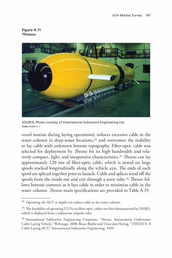
UUV Market Survey 147
vessel motion during laying operations), reduces excessive cable in the water column in deep-water locations,34 and overcomes the inability to lay cable with unknown bottom topography. Fiber-optic cable was selected for deployment by Theseus for its high bandwidth and rela-tively compact, light, and inexpensive characteristics.35 Theseus can lay approximately 120 nm of fiber-optic cable, which is stored on large spools stacked longitudinally along the vehicle axis. The ends of each spool are spliced together prior to launch. Cable and splices wind off the spools from the inside out and exit through a stern tube.36 Theseus fol-lows bottom contours as it lays cable in order to minimize cable in the water column. Theseus main specifications are provided in Table A.19.
34 Operating the AUV at depth can reduce cable in the water column.35 The feasibility of operating UUVs via fiber-optic cables was first demonstrated by NMRS, which is deployed from a submarine torpedo tube. 36 International Submarine Engineering Corporate, “Theseus, Autonomous Underwater Cable Laying Vehicle,” Web page, 2008; Bruce Butler and Vince den Hertog, “THESEUS: A Cable-Laying AUV,” International Submarine Engineering, 1999.
Figure A.11Theseus
RAND MG808-A.11
SOURCE: Photo courtesy of International Submarine Engineering Ltd.

148 A Survey of Missions for Unmanned Undersea Vehicles
Theseus uses a segmented aluminum-alloy pressure hull with free-flooding fiberglass hull sections fore and aft, making it an early exam-ple of modular construction for AUVs. The nose section contains a forward-looking obstacle-avoidance sonar, a computer-controlled bal-last tank, and acoustic transducers for telemetry and homing. During vehicle operation, a payload bay contains fiber-optic cable packs and buoyancy-compensation tanks.
Theseus is representative of future large AUVs.37 With develop-ment begun in 1992 under the U.S.-Canadian Spinnaker project, Theseus has been called a “grandparent” of modern AUVs.38 However, it is viewed as representative of the capabilities of large AUVs rather than as a candidate for one of the U.S. Navy’s future large AUVs. An AUV based on the Theseus design could fill mission needs for transporting
37 U.S. Department of the Navy, 2004, p. 69, uses Theseus to illustrate the large-vehicle class of UUVs under development.38 SPAWAR Systems Center, San Diego, “A Navy Perspective on UUVs,” briefing presented at the Marine Board Spring Meeting, May 6, 2004.
Table A.19Theseus Main Specifications
Feature Specifications
hull Length: 10.8 m (35 ft)Diameter: 1.3 m (50 in.)weight in air: 8,845 kg (19,500 lb)
Maximum speed 2.1 m/s (4 kt)
Operating depth 1000 m (3,281 ft)
Communication Acoustic low-level command link; radio-frequency float
Speed 2.1 m/s (4 kt) cruise speed
endurance At least 880 nm; >1 week
Sensors two magnetometers; still camera; video camera
payload payload volume: 2.5m3 (90 ft3)Maximum dry weight: 2,041 kg (4,500 lb)Maximum wet weight: 363 kg (800 lb)
SOUrCeS: Jane’s Information Group, Ltd., 2008; Butler and den hertog, 1999.

UUV Market Survey 149
supplies and equipment. It also has the speed, endurance, and naviga-tion capacities required for this mission. Acoustic and nonacoustic sen-sors could be deployed from Theseus-like AUVs.
An AUV based on Theseus could also be used for battlespace preparation. Theseus was designed to conduct bottom surveys and has ample mobility for this mission. Its payload volume could allow it to carry additional sensors.
The feasibility of using Theseus to carry a smaller UUV internally has also been explored. Similarly, given its ample volume, speed, endur-ance, and stability, the Theseus design might be adapted for long-term ISR missions. With the ability to pay out fiber-optic cable over long distances, such a UUV could collect and report data (including video) both clandestinely and in real time.
Fiber-optic cable deployed by a UUV from a Theseus-like UUV could be used to send instructions to the UUV as well as to receive data from the UUV. This capability would enable changes in mission plans once the UUV is under way. It would also provide ROV-like adaptabil-ity under unforeseen conditions.
Seahorse. Seahorse is large-displacement AUV designed and developed by ARL Penn State under the auspices of NAVOCEANO. The first Seahorse was delivered to NAVOCEANO in 2000. Two addi-tional Seahorse AUVs have been delivered to NAVOCEANO for use in bottom mapping, and ARL Penn State has built a fourth Seahorse for its own use.
Seahorse is a modular vehicle constructed using COTS compo-nents. It has four main modules (visible in Figure A.12), a nose sec-tion, and a tail section. The forward module contains a GPS mast; the second module contains CTD sensors; the third and fourth mod-ules contain a side-scan sonar. GPS navigation is augmented by inertial navigation. Seahorse communicates acoustically and electromagneti-cally. Note that ARL Penn State has modified its Seahorse for ISR mis-sions by adding two additional masts. Seahorse main specifications are provided in Table A.20.
Payload volume is approximately 10 ft3, and this space is initially dedicated to the side-scan sonar, acoustic Doppler current profiler, and CTD sensor. Neutral buoyancy is achieved by flooding variable-ballast
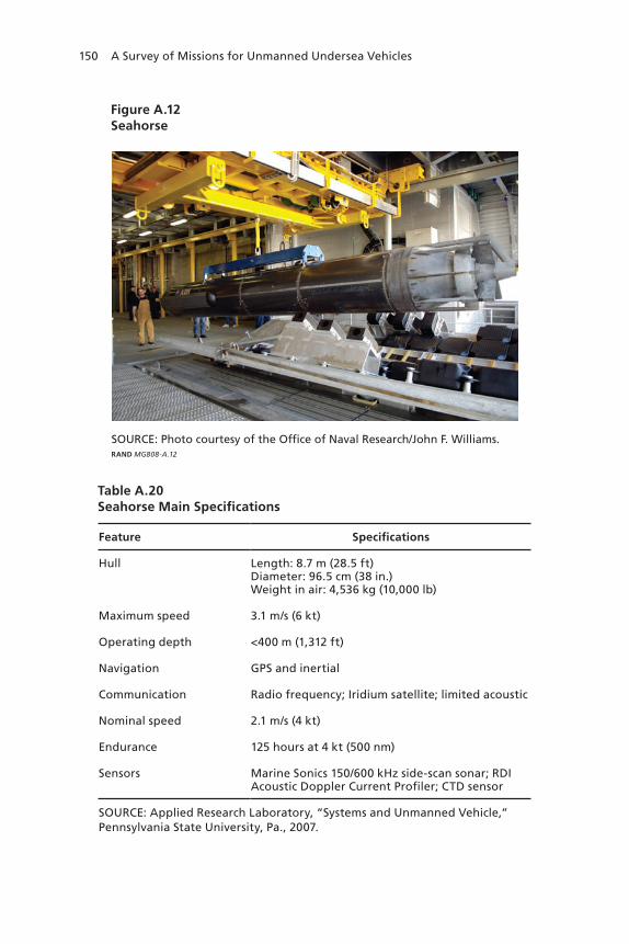
150 A Survey of Missions for Unmanned Undersea Vehicles
Figure A.12Seahorse
RAND MG808-A.12
SOURCE: Photo courtesy of the Office of Naval Research/John F. Williams.
Table A.20Seahorse Main Specifications
Feature Specifications
hull Length: 8.7 m (28.5 ft)Diameter: 96.5 cm (38 in.)weight in air: 4,536 kg (10,000 lb)
Maximum speed 3.1 m/s (6 kt)
Operating depth <400 m (1,312 ft)
navigation GpS and inertial
Communication radio frequency; Iridium satellite; limited acoustic
nominal speed 2.1 m/s (4 kt)
endurance 125 hours at 4 kt (500 nm)
Sensors Marine Sonics 150/600 khz side-scan sonar; rDI Acoustic Doppler Current profiler; CtD sensor
SOUrCe: Applied research Laboratory, “Systems and Unmanned Vehicle,” pennsylvania State University, pa., 2007.

UUV Market Survey 151
system tanks in the nose and tail sections. Propulsion power is cur-rently provided by 9,216 alkaline D-cell batteries that power a 5-hp motor,39 but these batteries will be replaced by rechargeable lithium ion batteries. In addition to allowing the vehicle’s batteries to be recharged in a convenient manner, this battery replacement will somewhat reduce the weight of Seahorse. The vehicle’s endurance will be unchanged.
As the most available and most capable large AUV, Seahorse was selected to demonstrate the concept of deploying large AUVs via an SSGN platform for SOF support. This concept was tested in early 2003 during Exercise Giant Shadow, when a Seahorse AUV was launched from a D5 ballistic-missile tube. The Seahorse AUV then simulated providing overwatch for a SOF over-the-beach operation. Seahorse also participated in a Persistent Littoral Undersea Surveillance Network exer-cise conducted in Monterey Bay in 2006. The collaborative, three-year effort to prepare Seahorse for launch from a D5 tube was remarkable.
ARL Penn State’s New Large AUV. After designing and construct-ing the Seahorse, ARL Penn State designed and has begun fabrica-tion of a new large AUV, Sea Lion, which will be significantly larger than Seahorse. Sea Lion will be 31 ft (9.4 m) long and have a 48-inch (1.22-m) diameter. Vehicle dry weight will be approximately 8 tons (7.3 tonnes). The vehicle will support modular payloads with a volume of up to 60 ft3 (1.7 m3) and a dry weight of up to 1,500 lb (680 kg). It will also support clip-on external payloads. Sea Lion will be used as a test bed for new technologies being developed at ARL Penn State. Recall that Sea Lion was mentioned previously in the context of pro-viding undersea test platforms (instead of that mission being carried out by a new LSV).
Gliders
Undersea gliders are AUVs that manipulate their buoyancy autono-mously, translating alternately positive and negative buoyancy forces into forward force and movement using wings. All gliders operate in a sawtooth manner as they move through the ocean. They are remark-able for their inherent energy efficiency and endurance.
39 Applied Research Laboratory, 2007.

152 A Survey of Missions for Unmanned Undersea Vehicles
Although the origins of the glider concept are in dispute, it is safe to say that Henry Stommel and Douglas C. Webb developed the first undersea glider. The Office of Naval Technology awarded them a con-tract in 1990 to develop a battery-powered prototype glider, and they tested the first undersea glider in 1991. Glider development was accel-erated in 1995 when ONR created three programs to develop the fol-lowing second-generation gliders: the Slocum glider (named in honor of Joshua Slocum, the first person to single-handedly circumnavigate the world) at the Webb Research Corporation; the Spray (named after Joshua Slocum’s sailing vessel) at the Scripps Institute of Oceanography; and the Seaglider at the University of Washington. The Webb Research Corporation has developed two versions of the Slocum glider. The first, the Slocum Battery Glider, uses alkaline batteries as an energy source. The second, the Slocum Thermal Glider, uses temperature differences in the ocean as an energy source.40
Broadly speaking, the Spray and the Slocum Battery Glider are the simplest of the three designs. Their aluminum hulls are shaped for low hydrodynamic drag. The Spray is optimized for long-duration, long-range, deep-ocean missions requiring energy efficiency. The Slocum Battery Glider is optimized for missions in shallow coastal environ-ments. The Slocum Thermal Glider is optimized for long-duration missions in waters with a well-developed thermocline.41 The Seaglider uses a hydrodynamic hull and an efficient mechanical system to maxi-mize its mission endurance (of 20–330 days).42
40 An excellent description of the Slocum Thermal Glider is provided in D. C. Webb, P. J. Simonetti, and C. P. Jones, “SLOCUM: An Underwater Glider Propelled by Environmental Energy,” IEEE Journal of Oceanographic Engineering, Vol. 26, No. 4, October 2001.41 As originally designed, the Slocum Thermal Glider used energy harvested from the ocean for propulsion only. Batteries provided energy for all other purposes. A new generation of the Slocum Thermal Glider, launched in December 2007, has no batteries. It runs entirely on energy derived from temperature differences in the ocean. As of March 3, 2008, this new glider has transited between the islands of St. Thomas and St. Croix (i.e., about 28 nm) more than 20 times (Woods Hole Oceanographic Institution, “News Release: Researchers Give New Hybrid Vehicle Its First Test-Drive in the Ocean,” February 6, 2008).42 T. P. Boyer, J. I. Antonov, H. E. Garcia, D. R. Johnson, R. A. Lacarnini, A. V. Mis-honov, M. T. Pitcher, O. K. Baranova, and I. V. Smolyar, “World Ocean Database 2005,”

UUV Market Survey 153
These gliders typically operate at speeds of about half a knot. However, they are optimized in design and operation for exploring the water column (i.e., for vertical movement) rather than for speed over ground. Small gliders operate in a scale regime equivalent to that of bats or small birds. Small gliders have been compared to gliding blimps. Their efficiency can be hampered by insufficient wing load-ing and excessive wetted area. They have also been found to suffer from inefficient buoyancy engines. Steep glide angles used to collect oceanographic data also reduce their efficiency. Cruise speeds of up to 10 kt could be achieved by reducing wing loading, using shallower dive angles, developing more-efficient buoyancy systems, and using larger gliders.43
This section describes the Spray, Slocum Battery Glider, and Sea-glider second-generation undersea gliders. It then describes the first fully autonomous glider in a new Liberdade-class of gliders.44
The Spray. The Spray’s design was developed by Bluefin Robot-ics in 2003 using technology licensed from the Scripps Institution of Oceanography. A Spray glider (like that shown in Figure A.13) manip-ulates its buoyancy by transferring hydraulic fluid between its interior and exterior. The Spray typically operates in a sawtooth profile between 200 m (656 ft) and 1,000 m (3,281 ft). The Spray surfaces intermit-tently to obtain GPS fixes and to communicate via an Iridium satellite system using antennas embedded in one wing. It exposes this wing for communication by rotating 90 degrees around its long axis. The Spray can operate to depths of 1,500 m (4,921 ft). Note that oceanographic-grade sensors for CTD comprise the vehicle’s standard sensor package. The Spray’s main specifications are shown in Table A.21.
in National Oceanographic Data Center, National Oceanic and Atmospheric Administration Atlas, U.S. Government Printing Office: Washington, D.C., 2006, p. 170.43 Scott Jenkins, Douglas E. Humphreys, Jeff Sherman, Jim Osse, Clayton Jones, Naomi Leonard, Jashua Graver, Ralf Bachmayer, Ted Clem, Paul Carroll, Philip Davis, Jon Berry, Paul Worley, and Joseph Wasyl, Underwater Glider Systems Study, Scripps Institution of Oceanography, University of California, Technical Report No. 53, 2003, pp. 6, 10.44 Liberdade was one of Joshua Slocum’s sailing vessels.

154 A Survey of Missions for Unmanned Undersea Vehicles
Figure A.13Spray Glider
RAND MG808-A.13
SOURCE: Photo courtesy of Bluefin Robotics Corporation.
Table A.21Spray Main Specifications
Feature Specifications
hull Length: 2.0 m (6.6 ft)Diameter: 20 cm (7.9 in.)weight in air: 51 kg (112 lb)payload: 3.5 kg (7.7 lb)
Lift surfaces wing span: 1.2 m (3.9 ft)
Batteries 52 lithium sulfuryl chloride D-cells
Communication Orbcomm satellite; GpS navigation
endurance nominal speed: 0.25 m/s (0.5 kt)range: 7,000 km (3,780 nm)Maximum mission duration: 330 days
Cost ($2002) Construction: $25,000refueling: $2,850
SOUrCe: russ e. Davis, Charles e. eriksen, and Clayton p. Jones, “Autonomous Buoyancy-Driven Underwater Gliders,” in Technology and Applications of Autonomous Underwater Vehicles, G. Griffiths, ed., London: taylor and Francis, 2003.

UUV Market Survey 155
The Woods Hole Oceanographic Institute and the North Atlantic Treaty Organization (NATO) Undersea Research Center jointly own a Bluefin Spray glider. In early 2007, Bluefin Robotics received a contract from Woods Hole to build four additional Spray vehicles.45
The Slocum Battery Glider. The Slocum Battery Glider is built by the Webb Research Corporation. It was designed for extended- duration science missions to depths of 200 m (656 ft). The Slocum Bat-tery Glider hull has three main separate sections and two wet sections located fore and aft. The cylindrical hull sections are made of OD 6061 T6 aluminum alloy. The nose-end cap is a machined pressure-resistant elliptical shape. Composite wings are normally swept at 45 degrees and are replaceable.
The forward wet section houses a 9–14 kHz transducer for active sonar use or for an acoustic modem. It also houses a 200-kHz trans-ducer for altimeter use (i.e., to measure distance above the bottom). The forward hull section houses mechanical, electrical, and electronic systems; batteries; and provisions for ballast weights. The large battery pack also serves as a mass moved for the pitch control. The mid-hull section is the payload bay. It has a nominal payload capacity of 3–4 kg (7–9 lb). The aft hull section is the strong back chassis that holds the glider together. It houses an air-pump system used to change buoyancy, a second battery, communications equipment, and other electronics.
The Slocum Battery Glider uses GPS and an Iridium satellite–communication system to report its status, position, and a sample of recorded sensor data for quality checking. Complete data files are retrieved upon mission completion. Slocum Battery Glider main speci-fications are shown in Table A.22.
A 15-element towed-array sonar with an acoustic aperture of 21 m (68.9 ft) has been developed for and tested with the Slocum Bat-tery Glider.46 A 16-element towed-array sonar for the Slocum Battery
45 Jane’s Information Group, Ltd., 2008.46 Paul Hursky, M. B. Porter, and M. Siderious, “Processing Data From a Low-Drag Array Towed by a Glider,” Heat, Light, and Sound, Inc., Vol. 120, No. 5, November 2006; S. M. Jesus and O. C. Rodriguez, “Glider Towed Array Tests During the Makai Experiment,” Pro-ceedings of the Eighth European Conference on Underwater Acoustics, 8th ECUA, June 2006.

156 A Survey of Missions for Unmanned Undersea Vehicles
Glider with an acoustic aperture of 10 m (32.8 ft) has also been devel-oped and tested.47
The Seaglider. The Seaglider (Figure A.14) was designed for long-range surveys; its highly streamlined hull provides energy efficiency. The Seaglider is produced by the Seaglider Fabrication Center of the University of Washington, which has built more than 20 Seaglider AUVs as of mid-2008.
The Seaglider’s whip-like tail is actually a novel mast design. Sea-glider obtains GPS fixes near the surface by pitching its nose down (as shown in Figure A.15) to expose the mast and GPS receiver. Seaglider’s main specifications are shown in Table A.23.
The Seaglider has participated in two military exercises to date as of mid-2008. In the summer of 2004, a Seaglider operated for six weeks in exercise RIMPAC-04, transmitting near–real-time environmen-tal data to the Naval Pacific Meteorology and Oceanography Center (NPMOC) Pearl Harbor, NPMOC San Diego, and NAVOCEANO
47 Marc S. Stewart,and J. Pavlos, “A Means to Networked Persistent Undersea Surveillance (U),” presented at the 2006 Submarine Technology Symposium, University of Washington, Tacoma, Wash., May 2006.
Table A.22Slocum Battery Glider Main Specifications
Feature Specifications
hull Length: 1.5 m (4.9 ft)Diameter: 21.3 cm (8.3 in.)weight in air 52 kg (115 lb)
Lift surfaces wing span: 1.0 m (3.3 ft)
Batteries 260 alkaline C-cells
Communication radio-frequency local area network; GpS
endurance nominal speed: 0.4 m/s (0.8 kt)range: 1,500 km (810 nm)Maximum mission duration: 20 days
Cost ($2002) Construction: $50,000refueling: $800
SOUrCe: hursky, porter, and Siderious, 2006.

UUV Market Survey 157
Figure A.14Seaglider
RAND MG808-A.14
SOURCE: Used with permission from James Osse.
Figure A.15Seaglider with Mast Exposed
RAND MG808-A.15
SOURCE: Photo provided by the Applied Physics Laboratory, University of Washingon. All rights reserved.

158 A Survey of Missions for Unmanned Undersea Vehicles
during the exercise. It completed 374 successful profiles over 170 nm in 25 days before experiencing command, control, and communications problems. In October 2004, a Seaglider participated in the ASW exer-cise TASWEX-04 in the East China Sea.
The XRay. Following the development of the Slocum, Spray, and Seaglider science gliders, development of a third-generation class of glid-ers, Liberdade, began in 2004. The most recent Liberdade prototype, the XRay, is the world’s largest undersea glider. The XRay features a 20-ft wingspan and a blended-fuselage design. This design maximizes its lift area and adds to its internal volume. Specifications such as hull length are irrelevant to the XRay’s flying-wing design.
XRay is designed to carry tactically relevant sensors, which makes it suitable for surveillance and other remote-sensing missions. A mid-frequency (1–10 kHz) sonar with 32 hydrophones has been integrated into the XRay’s wing. At-sea testing of the XRay began in the summer of 2006.
Table A.23Seaglider Main Specifications
Feature Specifications
hull Length: 1.8 m (5.9 ft)Diameter: 30 cm (11.8 in.)weight in air: 52 kg (115 lb)payload: 3.5 kg (8 lb)
Lift surfaces wing span: 1.0 m (3.3 ft)
Batteries 81 lithium thionyl chloride D-cellsa
Communication Cellular; Iridium satellite; GpS
endurance nominal speed: 0.25 m/s (0.5 kt)range: 4,500 km (2,430 nm)Maximum mission duration: 200 days
Cost ($2002) Construction: $60,000refueling: $1,375
SOUrCe: Davis, 2004.a Lithium thionyl chloride D-cells are not standard items like alkaline D-cells. they have about twice the energy density of alkaline D-cells.

UUV Market Survey 159
Gliders as large as the XRay have disadvantages. Most notably, they have a large turning radius. As a result, they cannot maneuver in constrained spaces, and they experience difficulty while operating in medium- to high-current regimes.48
Solar AUVs
The upper part of a solar AUV (SAUV) is a wing-like solar panel. These vehicles can provide long endurance (weeks to months) by charging their onboard batteries while on the surface during daylight hours. While charging their batteries, SAUVs navigate by GPS and commu-nicate remotely with users.49 The first SAUV was developed in a joint project funded by ONR and the Institute of Marine Technological Problems FEB RAD in Vladivostock, Russia.
SAUV II. The latest SAUV is the SAUV II. The SAUV II has been tested since 2004 for multiple capabilities, including cooperative oper-ations. As of mid-2008, five SAUV II vehicles have been built. SAUV II vehicles have operated continuously for months at a time by using solar energy to charge their lithium ion batteries during daylight hours. SAUV II main specifications are provided in Table A.24.
ROVs
The commercial-ROV community has grouped ROVs into the fol-lowing types: small vehicles, high-capacity electric vehicles, work-class vehicles, and heavy work-class vehicles.
Small-vehicle ROVs (“flying eyeballs”) are designed primarily to carry only sensors; they are generally not equipped with manip-ulators needed to affect their environment. However, a small-vehicle ROV engineered with sufficient buoyancy and other features needed to support small manipulators is described below. Small-vehicle ROVs
48 Eric O. Rogers, J. G. Gunderson, W. S. Smith, G. F. Denny, and P. J. Farley, “Underwa-ter Acoustic Glider,” International Geoscience and Remote Sensing Symposium, Vol. 3, 2004, pp. 2241–2244. 49 Jane’s Information Group, Ltd., 2008.

160 A Survey of Missions for Unmanned Undersea Vehicles
are typically all-electric and operate at depths of no more than 300 m (984 ft). They are used primarily for inspection and observation tasks. More than 1,000 small-vehicle ROVs are in use today. They generally cost $10,000–$100,000 each.
High-capacity electric ROVs are a relatively new development enabled by such technologies as brushless motors, personal com-puter–based control systems, and fiber-optic telemetry systems. These ROVs are notable for their quiet operation, ability to work in complex environments, and ability to work at great depths of up to 6,096 m (20,000 ft).
Work-class ROVs are the most widely used type of commercial ROVs. They perform such tasks as drilling support, light construc-tion support, and pipeline inspection. Their hydraulic arms have typi-cal payload capacities of 100–272 kg (220–600 lb). Some vehicles can through-frame lift more than 454 kg (1,000 lb).
Table A.24SAUV II Main Specifications
Feature Specifications
hull Length: 2.3 m (78 in.)width: 1.1 m (47 in.)pressure-tube length: 1.1 m (46 in.)pressure-tube external diameter: 22.8 cm (9 in.)weight in air: 168 kg (370 lb)
Batteries/solar cells Batteries: lithium ion (2 kwh)Solar array: 1 m2 for 85 w maximum power
Max operating depth 500 m (1,640 ft)
Communication Iridium satellite; acoustic modem; radio modema
endurance nominal speed: 0.4–1.5 m/s (0.75–3.0 kt)weeks to months
Sensors CtD
navigation GpS with dead reckoning
SOUrCe: Dick Blidberg, S. Mupparapu, S. Chappell, and r. Komerska, The SAUV II (Solar Powered AUV) Test Results 2004, Autonomous Undersea Systems Institute, 2005.a A Benthos “gateway” buoy has been used to act as a bridge that transmits acoustic transmissions using a Freewave radio-frequency modem.

UUV Market Survey 161
Heavy work-class ROVs can be fitted with power manipulator arms, special tool packages, and other peripheral equipment.50 They can lift and maneuver loads of up to 726 kg (1,600 lb), and their through-frame lift capacity is up to 5,000 kg (11,025 lb). They generally work at water depths of up to 3,000 m (9,843 ft).51
Small-Vehicle ROVs
VideoRay. VideoRay LLC has sold more than 500 small-vehicle ROVs as of mid-2008, making it one of the largest manufacturers of such vehicles. The U.S. Coast Guard recently placed a $451,405 order for VideoRay ROVs, accessories, and training. To put this price in per-spective, note that list prices of the nine models of VideoRay ROVs start at $5,995 and go up to $46,500. Like many other small-vehicle ROVs, VideoRay ROVs are attractive for their portability: They can be transported in two or three Pelican cases and weigh a total of 150 lb or less. A complete VideoRay ROV system is shown in Figure A.16.
Our focus is on the VideoRay Pro 3 XEGTO and the VideoRay Deep Blue, which differ primarily in their depth capabilities (500 ft
50 These include torque tools, linear actuators, cleaning tools, circular saws, wire cutters, and such specialized items as nondestructive inspection tools. 51 Remotely Operated Vehicle Committee of the Marine Technology Society, “ROV Back-ground,” Web page, undated.
Figure A.16VideoRay Pro 3 XEGTO System
RAND MG808-A.16
SOURCE: Image courtesy of VideoRay LLC.

162 A Survey of Missions for Unmanned Undersea Vehicles
[152 m] and 1,000 ft [305 m], respectively). They feature color-video cam-eras fore and black-and-white video cameras aft They can be equipped with simple manipulators. Notably, their stated top speed is 4.1 kt.
Phantom S2. The Phantom S2 is a small-vehicle ROV developed by Deep Ocean Engineering, Inc. The National Oceanographic and Atmospheric Administration Undersea Research Center (NURC) of the University of North Carolina–Wilmington operates a Phantom S2 that is equipped with a manipulator arm and associated sampling attach-ments. Phantom S2 main specifications are shown in Table A.25.
Stingray. The Stingray ROV is a product of Teledyne Benthos, a branch of Teledyne Technologies. The Canadian Border Services Agency accepted the Benthos Stingray ROV in 2005 for port- and har-bor-security duties. Stingray units are reported to have found and iden-tified objects, particularly illegal drugs, attached to ship hulls below the waterline. Critical hull areas of a vessel 200 m (656 ft) long can be inspected in two to three hours. This is consistent with the 2004 UUV Master Plan’s performance objective of searching a 1,000-ft ship with a 100-ft beam and 50-ft draft in 8 hours.52 Stingray’s main specifications are shown in Table A.26.
52 U.S. Department of the Navy, 2004, p. 35.
Table A.25NURC Phantom S2 Main Specifications
Feature Specifications
hull Length: 1.5 m (59 in.)width: 1 m (39 in.)height: 1 m (39 in.)weight in air: 70 kg (154 lb)
nominal speed 1.5 m/s (2.9 kt)
Operating depth 300 m (984 ft)
Sensors 12× zoom color camera; digital still camera and strobe; low-light SIt video camera; 500-w lighting system; dual scaling lasers; CtD; light transmission; oxygen
SOUrCe: Undersea research Center, “nUrC/SeGM Capabilities: remotely Operated Vehicle,” nOAA research Center, University of north Carolina–wilmington, wilmington, n.C., undated.
UUV Market Survey 163
High-Capacity Electric ROVs
Panther/Panther Plus. The Panther and the Panther Plus are high-capacity ROVs built by the British company Seaeye Marine Limited. The Panther, equipped for pipeline inspection, is shown in Figure A.17. Each Panther has a lighting system with four pan-and-tilt color-video cameras with zoom operation. Each vehicle has two identical manipu-lator arms and two buoyancy pods made of carbon fiber. The Panther’s electronics are contained in one of these pods. The other pod, which is empty, provides volume for additional equipment. The Panther was the first of the high-capacity electric ROV class of vehicles, which feature high power-to-weight ratios, use brushless DC thrusters (rather than hydraulic thrusters), and use plastic and composite structural materi-als. Precise movement is provided by velocity feedback systems. Pan-ther main specifications are provided in Table A.27.
Seaeye provides ROV thrust in each axis rather than speed in each axis. Seaeye states that thrust forward is 110 kg (243 lb), lateral thrust is 85 kg (187 lb), and vertical thrust is 75 kg (165 lb).
Although it is based on the Panther, the Panther Plus (Figure A.18) reflects a distinct set of design trade-offs. For example, where the Pan-ther is depth rated to 1,500 m (4,921 ft), the Panther Plus is depth rated to 1,000 m (3,281 ft). Furthermore, the Panther Plus is somewhat larger and significantly heavier than the Panther. Its two buoyancy pods are made of carbon fiber. One contains electronics, the other is empty. Main specifications for the Panther Plus are provided in Table A.28.
Table A.26Stingray Main Specifications
Feature Specifications
hull Length: 99 cm (38 in.)width: 46 cm (18.0 in.)height: 46 cm (18.0 in.)weight in air: 32 kg (70 lb)
nominal speed 0.75–1.0 kt vertically; 0.75–1.0 kt laterally; ~3 kt forward
Operating depth 350 m (1,148 ft)
Sensors 12× zoom color camera; low–light level black-and-white camera (optional)
SOUrCe: teledyne Benthos, Inc., Stingray, January 2007.
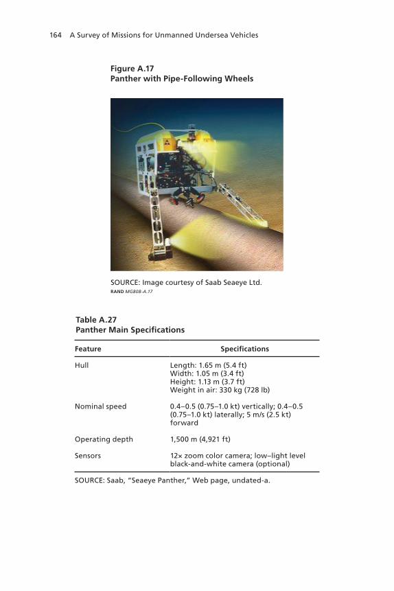
164 A Survey of Missions for Unmanned Undersea Vehicles
Figure A.17Panther with Pipe-Following Wheels
RAND MG808-A.17
SOURCE: Image courtesy of Saab Seaeye Ltd.
Table A.27Panther Main Specifications
Feature Specifications
hull Length: 1.65 m (5.4 ft)width: 1.05 m (3.4 ft)height: 1.13 m (3.7 ft)weight in air: 330 kg (728 lb)
nominal speed 0.4–0.5 (0.75–1.0 kt) vertically; 0.4–0.5 (0.75–1.0 kt) laterally; 5 m/s (2.5 kt) forward
Operating depth 1,500 m (4,921 ft)
Sensors 12× zoom color camera; low–light level black-and-white camera (optional)
SOUrCe: Saab, “Seaeye panther,” web page, undated-a.

UUV Market Survey 165
Figure A.18Panther Plus
RAND MG808-A.18
SOURCE: Photo courtesy of Saab Seaeye Ltd.
Table A.28Panther Plus Main Specifications
Feature Specifications
hull Length: 1.75 m (5.74 ft)width: 1.05 m (3.4 ft)height: 1.22 m (4.0 ft)weight in air: 500 kg (1,102 lb)
nominal speed 3.2 m/s (1.6 kt) laterally; 6 m/s (3.0 kt) forward
Operating depth 1,000 m (3,281 ft)
Sensors 12× zoom color camera; low–light level black-and-white camera (optional)
SOUrCe: Saab, “Seaeye rOV Comparison Chart,” web page, undated-b.

166 A Survey of Missions for Unmanned Undersea Vehicles
Note that the Panther Plus’ thrust forward (200 kg [485 lb]) and lateral thrust (170 kg [375 lb]) are twice that of the Panther. Its vertical thrust is 75 kg (165 lb).
The Russian Navy has selected the Panther Plus for SSAR. Their ROV will also be fitted with an 8-inch rotary disc cutter and a hydrau-lic guillotine cutter that can cut a wire rope of up to 38 mm (1.5 inches) in diameter and assist with debris clearance. This ROV will also be able to insert emergency life-support stores into a distressed submarine by connecting hoses and lines to the submarine’s salvage connections.
Work-Class ROVs
Scorpio. Scorpio is the brand name of a work-class ROV manu-factured by Perry Tritech. Scorpio ROVs are named sequentially in order of their manufacture. Thus, Scorpio 45 and Scorpio 58, which we use here to illustrate Scorpio configurations, refer to specific ROVs. All Scorpio ROVs have two manipulator arms and are able to move for-ward, astern, and laterally using thrusters.
Scorpio 45 is based in the UK’s Submarine Rescue Service head-quarters near Glasgow. As noted in Chapter Two, the Scorpio 45 was deployed in August 2005 when the Russian submersible Priz and its crew of seven were trapped by a fishing net off the Kamchatka Penin-sula. Scorpio 45 is 2.75 m (9 ft) long, 1.8 m (6 ft) high, and 1.8 m (6 ft) wide. It weighs 1,400 kg (3,086 lb) and, in normal operation, can carry a payload of up to 100 kg (220 lb). Scorpio 45 can operate to depths of up to 914 m (3,000 ft). Its stated maximum speeds are 4 kt forward, 3.25 kt astern, and 2.5 kt laterally.
Scorpio 58 is operated by Seaworks New Zealand, Ltd. It is 2.8 m (9.2 ft) long, 2.3 m (7.5 ft) high, and 2.4 m (7.9 ft) wide. It weighs 1,800 kg (3,968 lb) and, in normal operation, can carry a payload of up to 2,000 kg (4,409 lb). It can operate to depths of up to 1,000 m (3,281 ft). Its stated maximum speeds are 3 kt forward and 1.5 kt laterally.
Super Scorpio. The Super Scorpio is based on the Scorpio work-class commercial ROV. The U.S. Navy now operates two Super Scor-pio ROVs, the first having been delivered to the Navy in 1987 and the second in 1992. In 2000, Sailors from the Unmanned Vehicles Detach-ment used a Super Scorpio ROV to retrieve the flight data recorder from
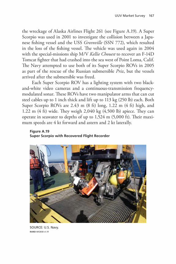
UUV Market Survey 167
the wreckage of Alaska Airlines Flight 261 (see Figure A.19). A Super Scorpio was used in 2001 to investigate the collision between a Japa-nese fishing vessel and the USS Greenville (SSN 772), which resulted in the loss of the fishing vessel. The vehicle was used again in 2004 with the special-missions ship M/V Kellie Chouest to recover an F-14D Tomcat fighter that had crashed into the sea west of Point Loma, Calif. The Navy attempted to use both of its Super Scorpio ROVs in 2005 as part of the rescue of the Russian submersible Priz, but the vessels arrived after the submersible was freed.
Each Super Scorpio ROV has a lighting system with two black-and-white video cameras and a continuous-transmission frequency-modulated sonar. These ROVs have two manipulator arms that can cut steel cables up to 1 inch thick and lift up to 113 kg (250 lb) each. Both Super Scorpio ROVs are 2.43 m (8 ft) long, 1.22 m (4 ft) high, and 1.22 m (4 ft) wide. They weigh 2,040 kg (4,500 lb) apiece. They can operate in seawater to depths of up to 1,524 m (5,000 ft). Their maxi-mum speeds are 4 kt forward and astern and 2 kt laterally.
Figure A.19Super Scorpio with Recovered Flight Recorder
RAND MG808-A.19
SOURCE: U.S. Navy.
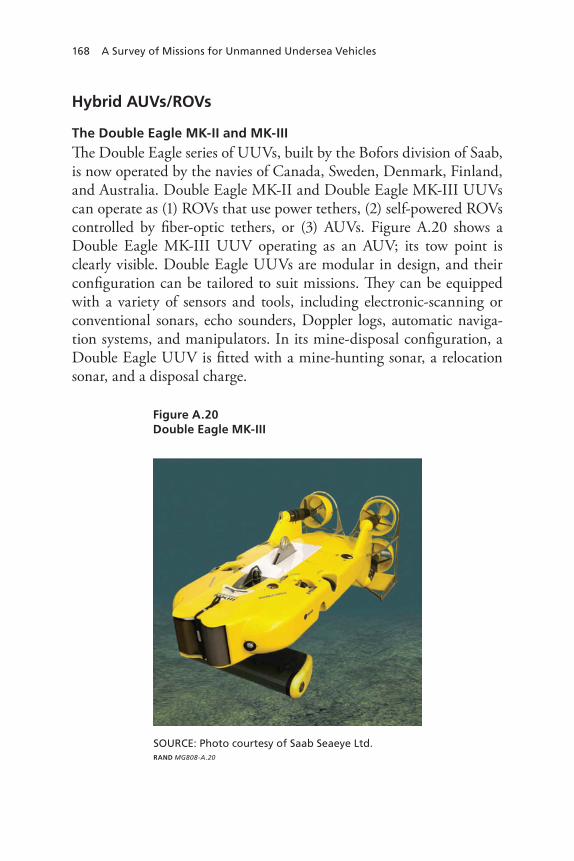
168 A Survey of Missions for Unmanned Undersea Vehicles
Hybrid AUVs/ROVs
The Double Eagle MK-II and MK-III
The Double Eagle series of UUVs, built by the Bofors division of Saab, is now operated by the navies of Canada, Sweden, Denmark, Finland, and Australia. Double Eagle MK-II and Double Eagle MK-III UUVs can operate as (1) ROVs that use power tethers, (2) self-powered ROVs controlled by fiber-optic tethers, or (3) AUVs. Figure A.20 shows a Double Eagle MK-III UUV operating as an AUV; its tow point is clearly visible. Double Eagle UUVs are modular in design, and their configuration can be tailored to suit missions. They can be equipped with a variety of sensors and tools, including electronic-scanning or conventional sonars, echo sounders, Doppler logs, automatic naviga-tion systems, and manipulators. In its mine-disposal configuration, a Double Eagle UUV is fitted with a mine-hunting sonar, a relocation sonar, and a disposal charge.
Figure A.20Double Eagle MK-III
RAND MG808-A.20
SOURCE: Photo courtesy of Saab Seaeye Ltd.
UUV Market Survey 169
The Double Eagle MK-II and Double Eagle MK-III were designed so that the vehicle, its winch system, and its control and sonar equip-ment can be fitted and transported in a standard shipping container. This allows the system to be moved from ship to ship and operated from vessels of opportunity. Double Eagle MK-II and Double Eagle MK-III vehicles can be launched as ROVs or AUVs. When launched as an ROV, the vehicle can release itself from its tether and operate as an AUV. As an AUV, the vehicle returns to a platform upon mission completion and docks with its tether while waiting, still in the water, for retrieval. In normal operation, a Double Eagle MK-II or Double Eagle MK-III runs several hundred meters ahead of its host vessel. Operating the ROV ahead of the host vessel has obvious advantages for ship safety. Additionally, operating the vehicle as an ROV (rather than as a tow body) allows operators to optimize vehicle depth for sonar performance. Having located a mine, a Double Eagle maneuvers as an ROV to place a charge within inches of the mine. The charge is remotely detonated to create a secondary explosion in the mine. In a recent NATO operation in the Adriatic Sea, the Danish MCM vessel HDMS Makrelen safely located and destroyed 25 bombs that had been dropped in the exercise area.53
Saab has released limited descriptive material for the Double Eagle MK-III. The vehicle weighs 350 kg (772 lb). As an ROV, its maximum forward speed is more than 3 kt, and its endurance is prac-tically unlimited. As an AUV, it has a maximum speed of more than 8 kt. Its endurance, which depends on the speed of operation, is over 10 hours and its maximum range is more than 50 km (27 nm).54
Nereus
Nereus, developed by the Woods Hole Oceanographic Institute, is designed to operate as an autonomous vehicle for wide-area surveys
53 Naval Team Denmark, Naval-Specialists Ready for a Mission, Copenhagen, Denmark, 2006, p. 22. Naval Team Denmark is an export organization of Danish defense industries within the maritime sector. 54 Bert Johansson, A Semi-Autonomous ROV as a Platform for Mine Warfare and Maritime Security Operations, SAAB Underwater Systems, undated.

170 A Survey of Missions for Unmanned Undersea Vehicles
and as a tethered vehicle for close-up sampling, photography, and mon-itoring. Nereus boasts several new technologies, including an armored fiber-optic minicable described as having the size and flexibility of dental floss. This cable is intended to give Nereus the ability to operate under ice as an ROV. The vehicle is also pioneering the use of high-performance ceramics (instead of more-dense syntactic foam) for flota-tion and for housing electronics to reduce in-water vehicle weight by 60 percent. This material enables Nereus to operate at depths of up to 11,000 m (36,089 ft). As an AUV, Nereus also features lithium ion bat-teries that can be recharged in as little as 30 minutes. Light-emitting diode technology helps give the vehicle its extreme-pressure tolerance and low level of power consumption. Note that Nereus has not under-gone sea trials and that its main performance parameters have not been released.
Biomimetic UUVs
Beyond conventional, torpedo-like AUVs, gliders, and ROVs, there are biomimetic AUVs that mimic such life-forms as fish and lobsters. Some of these biomimetic AUVs are literally the result of student proj-ects, but we limit our discussion to biomimetic AUVs that have been developed with federal funding. We group them into two categories: free-swimming AUVs and ambulatory AUVs. However, some biomi-metic AUVs defy easy categorization. For example, the Transphibian (Figure A.21) developed by Nekton Research of Durham, N.C., swims under water and walks on the sea floor or land. It would be used for conducting very-shallow-water mine clearance missions.
Swimming AUVs
Perhaps the best-known swimming AUV is the Robotuna, which was developed to study and improve the efficiency of underwater propul-sion. Since 1993, the Robotuna has been studied in tow-tank tests. The current version of the Robotuna is the Robotuna II, which is shown in Figure A.22.

UUV Market Survey 171
Figure A.21The Transphibian
RAND MG808-A.21
SOURCE: Photo courtesy of the Office of Naval Research/John F. Williams.
Figure A.22Robotuna II
RAND MG808-A.22
SOURCE: Photo courtesy of Michael Triantafyllou, Massachusetts Institute of Technology.

172 A Survey of Missions for Unmanned Undersea Vehicles
Ambulatory AUVs
The Biomimetic Underwater Robot Program at ONR is develop-ing neurotechnology based on the neurophysiology and behavior of animal models. One product of the project, the so-called Robolob-ster (Figure A.23), is an eight-legged ambulatory vehicle that is based on lobsters. The Robolobster is intended for autonomous remote-sens-ing operations in rivers, the littoral-zone ocean bottom, or both. Its robust adaptations can handle irregular bottom contours, currents, and surges. The project’s ultimate goal is to give the vehicle the ability to locate mines using chemical and other sensors in a surf zone.
The Remote Minehunting System
The AN/WLD-1 Remote Minehunting System (RMS) is an opera-tional USV currently in low initial-rate production for the U.S. Navy.
Figure A.23Robolobsters
RAND MG808-A.23
SOURCE: Photo courtesy of the Office of Naval Research/John F. Williams.

UUV Market Survey 173
Under this contract, each unit costs approximately $8.5 million.55 The first RMS system delivery to the U.S. Navy occurred in April 2007.
We discuss RMS for two reasons. First, when UUVs are con-sidered for MCM missions, RMS forces the question of why a UUV should be used instead of RMS. RMS has greater speed and endur-ance, an additional sensor (a laser line scanner), better ability to exam-ine mine-like objects from multiple perspectives (by virtue of its vari-able-depth sonar [VDS]), and better communications capability than any known existing or planned UUV. Furthermore, as noted above, RMS is now in production.
The second reason is that RMS provides a useful upper bound for UUV performance in several regards. In particular, because the RMS has continuous access to GPS, its navigational accuracy in ocean areas where differential GPS is unavailable is at least as good as that of any UUV. Tasks that are difficult for RMS to accomplish due to lim-ited navigational accuracy will be difficult for UUVs to accomplish for the same reason. In particular, it has been found that the navigational accuracy of RMS hampers redetection of mine-like objects.56
RMS was designed to operate semi-autonomously from a surface combatant to detect, classify, localize, and identify bottom and moored mine threats in shallow and deep water. It was intended to be deployed from DDG-51 Arleigh Burke–class destroyers and from LCSs. The system, shown in operation in Figure A.24, comprises the RMV and its towed VDS. RMS main specifications are provided in Table A.29.
The RMV, shown in Figure A.25, is an air-breathing, diesel-powered semi-submersible vehicle.57 Although frequently considered a UUV, several major differences at a system level separate the RMV from UUVs:
55 U.S. Department of the Navy, 2007b.56 U.S. Department of the Navy, 2007b.57 T. Tudron, “Target Reacquisition for Electro-Optic Identification in the AN/WLD-1(V)1 System,” briefing presented at the Fifth International Symposium on Technology and the Mine Problem, Monterey, Calif., April 21–25, 2002a.

174 A Survey of Missions for Unmanned Undersea Vehicles
Figure A.24The AN/WLD-1 RMS in Operation
RAND MG808-A.24
SOURCE: Image courtesy of the Lockheed Martin Corporation.
Table A.29AN/WLD-1 RMS Main Specifications
Feature Specifications
hull Length: 7 m (23 ft)Diameter: 120 cm (48 in.)weight in air: 6,360 kg (14,000 lb)
nominal Speed 6.2–8.2 m/s (12–16 kt)
Operating depth 4.3 m (14 ft)
navigation GpS; InS
Communication LOS; Oth
endurance 14+ hours at 12 kt (168 nm)
Sensors rMV: forward-looking sonar; Doppler sonar; obstacle-avoidance video cameraVDS: side-looking sonar; ahead-looking sonar; volume-search sonar; laser electro-optical identification sensor
SOUrCe: t. tudron, “target reacquisition for Identification in the An/wLD-1(V)1 System,” briefing presented at the Fifth International Symposium on technology and the Mine problem, Monterey, Calif., April 21–25, 2002b.

UUV Market Survey 175
Continuous diesel operation• .WhereastheTalismanAiscon-sideredararityamongUUVsforitsabilitytorechargeitsbatter-iesusinga smalldiesel engine, theRMScontinuouslyoperatesaCummins370Bmarinediesel engine.Thisengine is ratedat355brakehp;theDCelectricmotorstypicallyfoundinUUVsofferlessthan10hp.ThedieselsystemprovidestheRMSwithexceptionalenduranceandtopspeedshigherthanthoseofanyUUV.TheRMSusesasnorkelsystemtodrawairintothedieselengineandfordieselexhaust.Thissnorkelsystemalsoactsasanelectronicsmast.Continuous GPS navigation• .IncontrastwithUUVsthatperi-odically surface to update their navigation systemsusingGPS,theRMShasaGPSantennaexposedatalltimes.Continuous communication• .AnyUUVlackingatethercannotcommunicatecontinuouslywiththeoutsideworld,buttheRMS
Figure A.25RMV
RAND MG808-A.25
SOURCE: Image courtesy of the Lockheed Martin Corporation.
Mast• Video camera for obstacle
avoidance• Engine air induction• DLS and GPS antenna mounts
Control Surface Assembly• Fully articulated• 3,000 psi hydraulic
actuators
Pylon and Internal Components• Doppler sonar• FLS transmitter• 2,000-ft tow cable
VDS Deploy and Retrieve Section• VDS winch and cable drum• Keel-mounted camera• L&RS capture device
Fuel and ElectronicsSection• 289-gal capacity• Diesel fuel, marine
or JP-5• FLS receiver• Redundant data
recorders
Propulsion Section• Cummins “370B”
diesel engine• Commercial design,
multi-blade thruster• Marine, single-speed
gear box
• Length overall: 23 ft• Height, bottom of
pylon to masthead: 22 ft• Draft surfaced: 6 ft 8 in.• Draft submerged: 14 ft 10 in.• Weight: 12,850 lb

176 A Survey of Missions for Unmanned Undersea Vehicles
maintains direct line-of-sight radio communication with its host at all times.58
The AN/AQS-20 VDS used by RMS, shown in Figure A.26, uses multiple sonars and a laser scanner to positively differentiate between mines and mine-like objects that are not mines.
The RMS CONOP, illustrated in Figure A.27, begins with the RMS being launched from its host platform at a safe stand-off distance from a suspected minefield. The RMS reconnoiters with its assigned area by executing a preset mission profile consisting of maneuver way-points for parallel tracks within the search area. Computer-aided detec-tion (CAD) and computer-aided classification (CAC) processing in the VDS uses acoustic sensor data to detect, classify, and localize mine-like objects. Sensor data and target classifications are radioed back from
58 To cement the point that the RMV is not a UUV, note that the RMV appears on the cover of the 2007 edition of the Navy’s Unmanned Surface Vehicle Master Plan.
Figure A.26AN/AQS-20 VDS
RAND MG808-A.26
SOURCE: Photo courtesy of the Lockheed Martin Corporation.
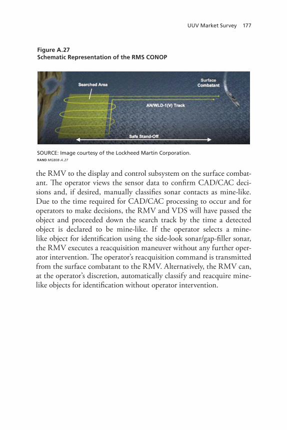
UUV Market Survey 177
the RMV to the display and control subsystem on the surface combat-ant. The operator views the sensor data to confirm CAD/CAC deci-sions and, if desired, manually classifies sonar contacts as mine-like. Due to the time required for CAD/CAC processing to occur and for operators to make decisions, the RMV and VDS will have passed the object and proceeded down the search track by the time a detected object is declared to be mine-like. If the operator selects a mine- like object for identification using the side-look sonar/gap-filler sonar, the RMV executes a reacquisition maneuver without any further oper-ator intervention. The operator’s reacquisition command is transmitted from the surface combatant to the RMV. Alternatively, the RMV can, at the operator’s discretion, automatically classify and reacquire mine-like objects for identification without operator intervention.
Figure A.27Schematic Representation of the RMS CONOP
RAND MG808-A.27
SOURCE: Image courtesy of the Lockheed Martin Corporation.


179
AppenDIx B
Models Used in This Analysis and Their Implications
We used two mathematical models during our study. Some of their results are presented in Chapter Two. The first model addresses AUV propulsion issues, such as energy density as a function of vehicle speed. The second model evaluates the hold-at-risk ASW CONOP.
The AUV Propulsion Model
The first-order model used to calculate AUV propulsion requirements is based on material provided to RAND by ARL Penn State for this study and validated against ARL Penn State data. The model assumes that at any constant speed, thrust and vehicle drag are in balance.1 It estimates propulsion power only. (So-called hotel power, used by sen-sors and other systems, needs to be included to calculate total power requirements.) The model is appropriate only for vehicles with cylindri-cal bodies.
Propulsion power is approximated as follows using a reference area (Aref),2 vehicle hydrodynamic drag coefficient (Cd), speed (U), pro-pulsor efficiency (ξp), and water density (ρ):3
1 This is not quite true because of interactions between the propulsor and the hull. 2 The cross-sectional area of the midbody is normally used.3 By definition, the density of pure water is 1,000 kg per m3. Ocean water, which is denser than fresh water, typically has a density of approximately 1,027 kg per m3.

180 A Survey of Missions for Unmanned Undersea Vehicles
PP = Aref × Cd × U3 × ρ / 2 × ξp.
To illustrate, consider a 21-inch (0.533-m) diameter vehicle with drag coefficient Cd = 0.13 and propulsor efficiency ξp = 0.87 that is operating at 6 kt (3.1 m/s). In this case, Aref = 0.223 m2 and U3 = 29.408 (m/s)3. Propulsion power is then calculated as
0.223 × 0.13 × 29.408 × 1027 / 2 × 0.87 kg · m2/s3.
Exact arithmetic yields the result 504.125 kg · m2/s3 (504.125 W).4 With 1 hp equaling approximately 745.7 W, this wattage equates to 0.68 shaft hp. With an allowance for motor losses, bearing and seal friction, and other losses totaling about 30 percent, the power draw at the source is about 720 W. Again, this does not include hotel loads.
A key feature of this equation is that, all other things being equal, propulsion power is proportional to the cube of speed. Thus, doubling speed requires an eight-fold increase in propulsion power. For the above vehicle, increasing speed from 6 kt to 12 kt increases required power to 5.4 hp (4 kW). Similarly, for a given form factor, doubling speed for a given endurance implies an eight-fold increase propulsion-system energy density. Also, all other things being equal, endurance at a given speed increases roughly with the diameter (or radius) of the vehicle. This is because for a fixed payload fraction, stored energy increases lin-early with vehicle volume (and thus with the cube of the radius of the vehicle)5 while power increases linearly with cross-sectional area (and thus with the square of the radius of the vehicle). The temporal endur-ance of a vehicle is the ratio of its stored energy (measured in kWh) to power (measured in kW).
4 This material has been provided with precision to allow readers to implement the model.5 Properly, the volume of a cylindrical vehicle body is Π × R2 × L, where R is the radius of the cylinder and L is its length. Hydrodynamic considerations roughly fix the ratio of vehicle length to diameter (i.e., L is proportional to R). Hence, the volume of the body of a cylindri-cal vehicle is proportional to the cube of its radius (or diameter).

Models Used in this Analysis and their Implications 181
The ASW Barrier Model
We used a simple line-barrier search model for this study. The model uses a cookie-cutter detection model with detection range (R0) assumed to be short relative to the length of the barrier (B). For a barrier patrolled by an AUV with speed U, the time to search the entire barrier front is B / U. For a target that penetrates the barrier at speed V, the time during which the target is detectable is R0 / V. The probability of detec-tion is thus PD = min(1, (R0 / V) / (B / U)).
For example, if the target is within the detection range of the barrier for 10 minutes and the AUV requires 20 minutes to patrol the barrier front, the probability of detection is 50 percent. If the target is within detection range of the barrier for 20 minutes and the AUV can patrol the barrier front in 10 minutes, however, then detection is certain. We preferred this model to classic barrier-detection models6 because the assumptions used in the latter models are violated in the case of slow-moving AUVs.
6 Perhaps the best such search models are available in B. O. Koopman, Search and Screen-ing, OEG Report No. 56, New York: The Summary Reports Group of the Columbia Univer-sity Division of War Research, 1946.


183
Bibliography
Alperi, Mike, “Navy Unmanned Maritime Systems,” PMS 403 briefing, Washington, D.C., April 2007.
Applied Research Laboratory, “Systems and Unmanned Vehicle,” Pennsylvania State University, Pa., 2007. As of January 20, 2009: http://www.arl.psu.edu/capabilities/at_suv.html
Arrieta, Paul R., F. Chandler, F. Crosby, and J. Purpura, “Above Water Obstacle Detection for the Remote Minehunting System (RMS),” Naval Surface Warfare Center, briefing presented at the ONR/AUVSI Joint Review, Orlando, Fla., February 12, 2008.
Benjamin, Michael R., D. Battle, D. Eickstedt, H. Schmidt, A. Balasuriya, “Autonomous Control of an Autonomous Underwater Vehicle Towing a Vector Sensor Array,” in Proc 2007 IEEE Int. Conf. on Robotics and Automation, Rome, Italy, April 2007, 2007, pp. 4562–4569.
Blidberg, Dick, S. Mupparapu, S. Chappell, and R. Komerska, The SAUV II (Solar Powered AUV) Test Results 2004, Autonomous Undersea Systems Institute, 2005.
Boyer, T. P., J. I. Antonov, H. E. Garcia, D. R. Johnson, R. A. Lacarnini, A. V. Mishonov, M. T. Pitcher, O. K. Baranova, and I. V. Smolyar, “World Ocean Database 2005,” in National Oceanographic Data Center, National Oceanic and Atmospheric Administration Atlas, U.S. Government Printing Office: Washington, D.C., 2006.
Butler, Bruce, and Vince den Hertog, “THESEUS: A Cable-Laying AUV,” International Submarine Engineering, 1999. As of July 1, 2007: http://www.ise.bc.ca/auv1003.html
Committee for the Review of ONR’s Air and Surface Weapons Technology, 2002 Assessment of the Office of Naval Research’s Air and Surface Weapons Technology Program, National Research Council, December 2002.
Committee for the Review of ONR’s Uninhabited Combat Air Vehicles Program, Review of ONR’s Combat Air Vehicles Program, Naval Studies Board, National Research Council, 2000.

184 A Survey of Missions for Unmanned Undersea Vehicles
Committee on Undersea Vehicles and National Needs National Research Council, Undersea Vehicles and National Needs, National Academies Press, 1996.
Cowen, Steve, Flying Plug: A Small UUV Designed for Submarine Connectivity, NCCOSC D746, Advanced Concepts Branch, Naval Command, Control and Ocean Surveillance Center, 1997.
Davis, Russ E., Charles E. Eriksen, and Clayton P. Jones, “Autonomous Buoyancy-Driven Underwater Gliders,” in Technology and Applications of Autonomous Underwater Vehicles, G. Griffiths, ed., London: Taylor and Francis, 2003.
Defense Industry Daily, “2 REMUS 600 Systems for UK Royal Navy,” Web page, September 23, 2007. As of January 19, 2009: http://www.defenseindustrydaily.com/2-remus-600-systems-for-uk-royal-navy-03860/
Defense News, “In Deep Water: Improved Sub Communications Sought,” Web page, February 11, 2008. As of January 19, 2009: http://www.defensenews.com/story.php?i=3372388&c=FEA&s=TEC
Defense Systems Daily, “US Navy Achieves Two-Way, Networked Connectivity,” Web page, February 29, 2008. As of January 19, 2009: http://defence-data.com/current/page39556.htm
Deitz, Daniel, “Expendable Glider for Oceanographic Research,” Navy STTR FY2008A, Topic N08-T016, February 18, 2008.
Dzielski, J. E., M. J. Bregar, and D. L. McDowell, “NAVOCEANO Seahorse AUV Participation in the GIANT SHADOW Experiment,” Oceans Proceedings, Vol. 2, September 22–26, 2003, pp. 1127–1131.
El-Hawary, F., The Ocean Engineering Handbook, Boca Raton, Fla.: CRC Press LLC, 2001.
Federation of American Scientists, “UUV Program Plan,” Web page, undated. As of March 10, 2009: http://www.fas.org/irp/program/collect/uuvprogu.html
Fletcher, B., and R. Wernli, “Expanding Missions for Small Unmanned Undersea Vehicles (UUVs),” 22nd International Conference on Offshore Mechanics and Arctic Engineering, OMAE2003-37254, Cancun, Mexico, June 8–13, 2003.
GlobalSecurity.org, “Large Scale Vehicle LSV,” Web page, undated, last updated April 27, 2005. As of January 19, 2009: http://www.globalsecurity.org/military/systems/ship/lsv.htm
———, “Military: Littoral Combat Ship,” c. 2003, last updated April 27, 2005. As of March 10, 2009: http://www.globalsecurity.org/military/library/report/2003/LCSCONOPS.htm
Griffiths, Gwyn, Technologies and Applications of Autonomous Underwater Vehicles, UK: Routledge, 2002.

Bibliography 185
Herr, Frank, “DoN S&T Focus Area: Assure Access and Hold at Risk,” briefing presented at the 2007 NDIA Naval S&T Partnership Conference, August 1, 2007.
Hursky, Paul, M. B. Porter, and M. Siderious, “Processing Data From a Low-Drag Array Towed by a Glider,” Heat, Light, and Sound, Inc., Vol. 120, No. 5, November 2006.
Hydroid, Inc., “Vehicles, REMUS 600,” Web page, 2006. As of January 19, 2009: http://www.hydroidinc.com/remus600.html
International Submarine Engineering Corporate, “Theseus, Autonomous Underwater Cable Laying Vehicle,” Web page, 2008. As of January 20, 2009: http://www.ise.bc.ca/theseus.html
Jalving, Bjørn, Magne Mandt, and Ove Kent Hagen, “Terrain Referenced Navigation of AUVs and Submarines Using Multibeam Echo Sounders,” Norwegian Defence Research Establishment, 2004. As of January 19, 2009: http://www.mil.no/multimedia/archive/00065/UDT_Europe_2004__BJ__65343a.pdf
Jane’s Information Group, Ltd., “Executive Overview: Underwater Warfare,” Web page, 2008.
Jenkins, Scott, Douglas E. Humphreys, Jeff Sherman, Jim Osse, Clayton Jones, Naomi Leonard, Jashua Graver, Ralf Bachmayer, Ted Clem, Paul Carroll, Philip Davis, Jon Berry, Paul Worley, and Joseph Wasyl, Underwater Glider Systems Study, Scripps Institution of Oceanography, University of California, Technical Report No. 53, 2003.
Jesus, S. M., and O. C. Rodriguez, “Glider Towed Array Tests During the Makai Experiment,” Proceedings of the Eighth European Conference on Underwater Acoustics, 8th ECUA, June 2006.
Johansson, Bert, A Semi-Autonomous ROV as a Platform for Mine Warfare and Maritime Security Operations, SAAB Underwater Systems, undated.
Jones, Clayton, Slocum Gliders—A Component of Operational Oceanography, Webb Research Corporation and Rutgers University, undated.
Konetzni, Albert, “Mine Warfare,” CHIPS—The Department of the Navy Information Technology Magazine, Winter 2003. As of January 19, 2009: http://www.chips.navy.mil/archives/03_winter/webpages/mine_warfare.htm
Kongsberg, “Autonomous Underwater Vehicles—HUGIN AUV’s,” Web page, 2009. As of January 19, 2009: http://www.km.kongsberg.com/auv
Kongsberg Maritime, “Hugin 1000 System Description, Military Version,” white paper, November 2003.
Kongsberg-Simrad, HUGIN 3000: An Autonomous Underwater Vehicle (AUV) for Accurate and Efficient Seabed Mapping, Norway: Kongsberg Simrad A/S, 2006.

186 A Survey of Missions for Unmanned Undersea Vehicles
Koopman, B. O., Search and Screening, OEG Report No. 56, New York: The Summary Reports Group of the Columbia University Division of War Research, 1946.
Lacroix, Frank W., Robert W. Button, Stuart E. Johnson, and John R. Wise, A Concept of Operations for a New Deep-Diving Submarine, Santa Monica, Calif.: RAND Corporation, MR-1395-NAVY, 2002. As of January 15, 2009: http://www.rand.org/pubs/monograph_reports/MR1395/
Maguer, A., W. L. J. Fox, A. Tesei, E. Bovio, and S. Fioravanti, Buried Mine Detection and Classification (Research Summary 1996-1999), SACLANT Undersea Research Center Report, SR-315, 1999.
Medeiros, Maria G., “Weapons and Vehicles Needs,” briefing presented at CEROS Industry Day, Naval Undersea Warfare Center, November 13, 2007.
Nakhlawi, Elham, Mustafa Al Arab, Caroline Faraj, Tess Eastment, Aneesh Raman, and Brad Lendon, “Third Undersea Internet Cable Cut in Mideast,” CNN, February 1, 2008. As of January 19, 2009: http://www.cnn.com/2008/WORLD/meast/02/01/internet.outage/
National Research Council, Autonomous Vehicles in Support of Naval Operations, Washington, D.C.: The National Academies Press, 2005.
Naval Team Denmark, Naval-Specialists Ready for a Mission, Copenhagen, Denmark, 2006. As of January 20, 2009: http://www.navalteam.dk/NTD_magazine/Naval_team_profil_06_07.pdf
Naval Warfare Development Command, Littoral Combat Ship: Concept of Operations, Newport, R.I., 2004.
NAVSEA Shipbuilding Office, “Ship Hull Classification Symbols,” Web page, undated. As of January 19, 2009: http://www.nvr.navy.mil/nvrships/S_TYPE.HTM
Office of the Secretary of Defense, Joint Publication 1-02, Dictionary of Military and Associated Terms, April 12, 2001, as amended through June 13, 2007a.
———, Unmanned Systems Roadmap (2007–2032), Washington, D.C., December 10, 2007b.
Office of the Under Secretary of Defense for Acquisition, Technology, and Logistics, “Treaty Compliance, Strategic Arms Reduction Treaty (START I),” Web page, December 5, 1994. As of January 19, 2009: http://www.dod.mil/acq/acic/treaties/start1/
O’Rourke, Ronald, Navy Attack Submarine Force-Level Goal and Procurement Rate: Background and Issues for Congress, CRS Report for Congress, Order Code RL32418, June 11, 2007.
Pebody, M., and Robert Sutton, “Autonomous Underwater Vehicle Collision Avoidance for Under-Ice Exploration,” Proceedings of the Institution of Mechanical

Bibliography 187
Engineers, Part M: Journal of Engineering for the Maritime Environment, Vol. 222, No. 2, 2008, pp. 53–66.
Purdy, Ellen, “DoD Unmanned Systems Integrated Roadmap,” briefing presented at the AUVSI Unmanned Systems Program Review 2008, OUSD(ATL)/PSA/LW&M, February 28, 2008.
Remotely Operated Vehicle Committee of the Marine Technology Society, “ROV Background,” Web page, undated. As of January 20, 2009: http://www.rov.org/info.cfm
Rogers, Eric O., J. G. Gunderson, W. S. Smith, G. F. Denny, and P. J. Farley, “Underwater Acoustic Glider,” International Geoscience and Remote Sensing Symposium, Vol. 3, 2004, pp. 2241–2244.
Saab, “Seaeye Panther,” Web page, undated-a. As of January 30, 2009: http://www.seaeye.com/panther.html
———, “Seaeye ROV Comparison Chart,” Web page, undated-b. As of January 30, 2009: http://www.seaeye.com/comparerovs.html
Sherman, T., “Deployment Approach Provides Stable Height of Eye for Sensor Visibility,” report presented at the AIAA 3rd Unmanned Unlimited Technical Conference, Workshop and Exhibit, Chicago, Ill., September, 2004.
Siegrest, Paul, “Unmanned Maritime Vehicle Systems Update,” briefing presented at the AUVSI Unmanned System Program Review 2008, PMS 403, February 28, 2008.
SPAWAR Systems Center, San Diego, “A Navy Perspective on UUVs,” briefing presented at the Marine Board Spring Meeting, May 6, 2004. As of February 20, 2007: http://gulliver.trb.org/conferences/MB/spring04/Navy-1.pdf
Stewart, Marc S., and J. Pavlos, “A Means to Networked Persistent Undersea Surveillance (U),” presented at the 2006 Submarine Technology Symposium, University of Washington, Tacoma, Wash., May 2006.
Stuart, Scott, “Enabling Access: Acquisition Perspective,” PMS-EOD briefing to the Mine Warfare Association Meeting, May 2005.
Teledyne Benthos, Inc., Stingray, January 2007. As of May 11, 2008: http://www.benthos.com/PDF/stingray.pdf
Tudron, T., “Target Reacquisition for Electro-Optic Identification in the AN/WLD-1(V)1 System,” briefing presented at the Fifth International Symposium on Technology and the Mine Problem, Monterey, Calif., April 21–25, 2002a.
———, “Target Reacquisition for Identification in the AN/WLD-1(V)1 System,” briefing presented at the Fifth International Symposium on Technology and the Mine Problem, Monterey, Calif., April 21–25, 2002b.
188 A Survey of Missions for Unmanned Undersea Vehicles
Ulrich, Richard, and James Watson, Supervisory Control of Untethered Undersea Systems: A New Paradigm Verified, San Diego, Calif., 1995.
U.S. Department of the Navy, Naval Warfare Publication 3-15, Mine Warfare, 1996.
———, The Navy Unmanned Undersea Vehicle (UUV) Master Plan, April 20, 2000.
———, Fiscal Year (FY) 2002 Amended Budget Submission: Justification of Estimates, Research, Development, Test & Evaluation, Navy Budget Activity 4, June 2001a.
———, Fiscal Year (FY) 2002 Budget Estimates Submitted to Congress: Justification of Estimates, Operation & Maintenance, Budget Activity 2, June 2001b.
———, A Navy Strategic Plan for Small Unmanned Underwater Vehicles, PMS-EOD, 2002.
———, The Navy Unmanned Undersea Vehicle (UUV) Master Plan, November 2004.
———, Anti-Submarine Warfare, Concept of Operations for the 21st Century, February 3, 2005.
———, Fiscal Year (FY) 2007 Budget Submission, Weapons Procurement, February 2006.
———, Fiscal Year (FY) 2008/2009 Budget Estimates: Justification of Estimates, Research, Development, Test & Evaluation, Navy, Budget Activity 7, February 2007a.
———, The Navy Unmanned Surface Vehicle (USV) Master Plan, July 2007b.
———, Fiscal Year (FY) 2009 Budget Estimates: Other Procurement, Activities 5–7, February 2008.
U.S. Government Accountability Office, Overcoming Challenges Key to Capitalizing on Mine Countermeasures Capabilities, GAO-08-13, October 2007.
Undersea Research Center, “NURC/SEGM Capabilities: Remotely Operated Vehicle,” NOAA Research Center, University of North Carolina–Wilmington, Wilmington, N.C., undated. As of January 20, 2009: http://www.uncw.edu/nurc/systems/rov_one_pager.pdf
Webb, D. C., P. J. Simonetti, and C. P. Jones, “SLOCUM: An Underwater Glider Propelled by Environmental Energy,” IEEE Journal of Oceanographic Engineering, Vol. 26, No. 4, October 2001.
Webb Research Corporation, Slocum Battery Glider Operations Manual, version 1.5, East Falmouth, Mass., June 17, 2004.
Bibliography 189
Wernli, Robert L., Low Cost UUVs for Military Missions: Is the Technology Ready? Space and Naval Warfare Systems Center, San Diego, Calif., undated.
Woods Hole Oceanographic Institution, “News Release: Researchers Give New Hybrid Vehicle Its First Test-Drive in the Ocean,” February 6, 2008. As of January 20, 2009: http://www.whoi.edu/page.do?pid=7545&tid=282&cid=37008&ct=162
———, “Oceanographic Systems Laboratory, Autonomous Underwater Vehicle, REMUS,” Web page, last updated November 19, 2008. As of January 19, 2009: http://www.whoi.edu/page.do?pid=29856