![Psychiatric Effects of Solitary Confinement 102716 Item 3 Dr...p325 Grassian book pages.doc 12/18/2006 2006] Psychiatric Effects of Solitary Confinement 329 observed in individuals](https://static.fdocuments.us/doc/165x107/5f8270d13899707dbf448ed0/psychiatric-effects-of-solitary-confinement-102716-item-3-dr-p325-grassian-book.jpg)
A survey of image registration techniquesgerig/CS6640-F2010/p325-brown.pdf · A Survey of Image...
52
A Survey of Image Registration Techniques LISA GOTTESFELD BROWN Department of Computer Sctence, Colunzbza Unzl,ersity, New York, NY 10027 Registration M a fundamental task in image processing used to match two or more pictures taken, for example, at different times, from different sensors, or from different viewpoints. Virtually all large systems which evaluate images require the registration of images, or a closely related operation, as an intermediate step. Specific examples of systems where image registration is a significant component include matching a target with a real-time image of a scene for target recognition, monitoring global land usage using satellite images, matching stereo images to recover shape for autonomous navigation, and aligning images from different medical modalities for diagnosis. Over the years, a broad range of techniques has been developed for various types of data and problems. These techniques have been independently studied for several different applications, resulting in a large body of research. This paper organizes this material by estabhshing the relationship between the variations in the images and the type of registration techniques which can most appropriately be applied. Three major types of variations are distinguished. The first type are the variations due to the differences in acquisition which cause the images to be misaligned. To register images, a spatial transformation is found which will remove these variations. The class of transformations which must be searched to find the optimal transformation is determined by knowledge about the variations of this type. The transformation class in turn influences the general technique that should be taken. The second type of variations are those which are also due to differences in acquisition, but cannot be modeled easily such as lighting and atmospheric conditions. This type usually effects intensity values, but they may also be spatial, such as perspective distortions, The thn-d type of variations are differences in the images that are of interest such as object movements, growths, or other scene changes. Variations of the second and third type are not directly removed by registration, but they make registration more difficult since an exact match is no longer possible. In particular, it is critical that variations of the third type are not removed. Knowledge about the characteristics of each type of variation effect the choice of feature space, similarity measure, search space, and search strategy which will make up the final technique. All registration techniques can be viewed as different combinations of these choices. This framework M useful for understanding the merits and relationships between the wide variety of existing techniques and for assisting in the selection of the most suitable Iechnique for a specific problem. Categories and Subject Descriptors: A. 1 [General Literature]: Introductory and Survey; 1.2.10 [Artificial Intelligence]: Vision and Scene Understanding; 1.4 [Computing Methodologies]: Image Processing; 1.5 [Computing Methodologies]: Pattern Recognition General Terms: Algorithms, Design, Measurement, Performance Additional Key Words and Phrases: Image registration, image warping, rectification, template matching Permission to copy without fee all o. part of this material is granted provided that the copies are not made or distributed for direct commercial advantage, the ACM copyright notice and the title of the publication and Its data appear, and notie is given that copying is by permission of the Associatlon for Computing Machinery. To copy otherwise, or to repubhsh, requires a fee and/or specific permission. @ 1992 ACM 0360-0300/92/’ 1200-0325 $01.50 ACM Comput,ng Surveys,VoI 24, No. 4, December 1992
Transcript of A survey of image registration techniquesgerig/CS6640-F2010/p325-brown.pdf · A Survey of Image...

A Survey of Image Registration Techniques
LISA GOTTESFELD BROWN
Department of Computer Sctence, Colunzbza Unzl,ersity, New York, NY 10027
Registration M a fundamental task in image processing used to match two or morepictures taken, for example, at different times, from different sensors, or from differentviewpoints. Virtually all large systems which evaluate images require the registrationof images, or a closely related operation, as an intermediate step. Specific examples ofsystems where image registration is a significant component include matching a targetwith a real-time image of a scene for target recognition, monitoring global land usageusing satellite images, matching stereo images to recover shape for autonomousnavigation, and aligning images from different medical modalities for diagnosis.
Over the years, a broad range of techniques has been developed for various types ofdata and problems. These techniques have been independently studied for severaldifferent applications, resulting in a large body of research. This paper organizes thismaterial by estabhshing the relationship between the variations in the images and thetype of registration techniques which can most appropriately be applied. Three majortypes of variations are distinguished. The first type are the variations due to thedifferences in acquisition which cause the images to be misaligned. To register images,a spatial transformation is found which will remove these variations. The class oftransformations which must be searched to find the optimal transformation isdetermined by knowledge about the variations of this type. The transformation class inturn influences the general technique that should be taken. The second type ofvariations are those which are also due to differences in acquisition, but cannot bemodeled easily such as lighting and atmospheric conditions. This type usually effectsintensity values, but they may also be spatial, such as perspective distortions, Thethn-d type of variations are differences in the images that are of interest such as objectmovements, growths, or other scene changes. Variations of the second and third typeare not directly removed by registration, but they make registration more difficultsince an exact match is no longer possible. In particular, it is critical that variations ofthe third type are not removed. Knowledge about the characteristics of each type ofvariation effect the choice of feature space, similarity measure, search space, andsearch strategy which will make up the final technique. All registration techniques canbe viewed as different combinations of these choices. This framework M useful forunderstanding the merits and relationships between the wide variety of existingtechniques and for assisting in the selection of the most suitable Iechnique for aspecific problem.
Categories and Subject Descriptors: A. 1 [General Literature]: Introductory andSurvey; 1.2.10 [Artificial Intelligence]: Vision and SceneUnderstanding; 1.4[Computing Methodologies]: Image Processing; 1.5 [Computing Methodologies]:
Pattern Recognition
General Terms: Algorithms, Design, Measurement, Performance
Additional Key Words and Phrases: Image registration, image warping, rectification,template matching
Permission to copy without fee all o. part of this material is granted provided that the copies are not madeor distributed for direct commercial advantage, the ACM copyright notice and the title of the publicationand Its data appear, and notie is given that copying is by permission of the Associatlon for ComputingMachinery. To copy otherwise, or to repubhsh, requires a fee and/or specific permission.@ 1992 ACM 0360-0300/92/’ 1200-0325 $01.50
ACM Comput,ng Surveys,VoI 24, No. 4, December1992

326 “ Lisa G. Brown
1
CONTENTS
1. INTRODUCTION2 IMAGE REGISTRATION IN THEORY
2 1 Defimtlon22 Tran~f~=matlon23 Image Varlatlons24 Rectlticatlon
3 REGISTRATION METHODS31 Correlatmn and Sequential Methods32 Fourier Methods33 Point Mapping34 E1.ast,cModel-BasedMatch]ng35 Summary
4 CHARACTERISTICS OF REGISTRATIONMETHODS41 Feature Space42 SlmdarIty Measure43 SearchSpaceand Strategy44 Summary
~—
INTRODUCTION
A frequent problem arises when imagestaken, at different times, by differentsensors or from different viewpoints needto be compared. The images need to bealigned with one another so that differ-ences can be detected. A similar problemoccurs when searching for a. prototype ortemplate in another image. To find theoptimal match for the template in theimage, the proper alignment between theimage and template must be found. All ofthese problems, and many related varia-tions, are solved by methods that per-form image registration. A transforma-tion must be found so that the points inone image can be related to their corre-sponding points in the other. The deter-mination of the optimal transformationfor registration depends on the types ofvariations between the images. The ob-jective of this paper is to provide a frame-work for solving image registration tasksand to survey the classical approaches.
Registration methods can be viewed asdifferent combinations of choices for thefollowing four components:
(1) a feature space,
(2) a search space,
(3) a search strategy, and
(4) a similarity metric.
The feature space extracts the informa-tion in the images that will be used formatching. The search space is the classof transformations that is capable ofaligning the images. The search strategy
decides how to choose the next transfor-mation from this space, to be tested inthe search for the optimal transforma-tion. The similarity metric determinesthe relative merit for each test. Searchcontinues according to the search strat-egy until a transformation is found whosesimilarity measure is satisfactory. As weshall see, the types of variations presentin the images will determine the selec-tion for each of these components.
For example, consider the problem ofregistering the two x-ray images of chesttaken of the same patient at differenttimes shown in Figure 1. Properly align-ing the two images is useful for detect-ing, locating, and measuring pathologicaland other physical changes. A standardapproach to registration for these imagesmight be as follows: the images mightfirst be reduced to binary images by de-tecting the edges or regions of highestcontrast using a standard edge detectionscheme. This removes extraneous infor-mation and reduces the amount of datato be evaluated. If it is thought that theprimary difference in acquisition of theimages was a small translation of thescanner, the search space might be a setof small translations. For each transla-tion of the edges of the left image ontothe edges of the right image, a measureof similarity would be computed. A typi-cal similarity measure would be the cor-relation between the images. If the simi-larity measure is computed for all trans-lations then the search strategy is simplyexhaustive. The images are registeredusing the translation which optimizes thesimilarity criterion. However, the choiceof using edges for features, translationsfor the search space, exhaustive searchfor the search strategy and correlationfor the similarity metric will influencethe outcome of this registration. In fact,in this case, the registration will un-doubtable be unsatisfactory since the im-ages are misaligned in a more complex
ACM Computmg Surveys, Vol. 24, No. 4, December 1992

image Registration Techniques ● 327
Figure 1. X-ray images of a patient’s chest, takenat different times. (Thanks to A. Goshtasby.)
way than translation. By establishing therelationship between the variations be-tween the images and the choices for thefour components of image registration,this paper provides a framework for un-derstanding the exisiting registrationtechniques and also a methodology forassisting in the selection of the appropri-ate technique for a specific problem. Byestablishing the relationship between thevariations among the images and thechoices for the four components of imageregistration, this paper provides a frame-work for understanding the existing reg-istration techniques and also a methodol-ogy for assisting in the selection ofthe appropriate technique for a specificproblem.
The need to register images has arisenin many practical problems in diversefields. Registration is often necessary for(1) integrating information taken fromdifferent sensors, (2) finding changes inimages taken at different times or underdifferent conditions, (3) inferring three-dimensional information from images inwhich either the camera or the objects inthe scene have moved, and (4) for model-based object recognition [Rosenfeld andKak 1982].
An example of the first case is shownin Figare 2. In this figure the upper rightimage is a Magnetic Resonance Image
(MRI) of a patient’s liver. From this im-age it is possible to discern the anatomi-
cal structures. Since this image is similarto what a surgeon will see during anoperation, this image might be used to
Figure 2. The top left image is a SPECT image ofa patient’s liver. The top right shows the sameregion viewed by MRI. A contour was manuallydrawn around the liver in the MRI image. Thelocation of this contour in the SPECT image showsthe mismatch between the two images. At the bot-tom right the MRI image has been registered to theSPECT image, and the location of the transformedcontour is shown on the SPECT image, bottom left.A brief description of the registration method em-ployed is in Section 3.3.3. (Courtesy of QSH, animage display and processing toolkit [Noz 1988]and New York University I would like to thank B.A. Birnbaum, E. L. Kramer, M. E. Noz, and J. J.Sanger of New York University, and G. Q. Maguire,Jr. of Columbia University.)
plan a medical procedure. The upper leftimage is from single photon emissioncomputed tomography (SPECT). It showsthe same anatomical region after intra-venous administration of a Tc-99m (a ra-dionuclide) labeled compound. This im-age depicts some of the functional behav-ior of the liver (the Tc-99m compoundbinds to red blood cells) and can moreaccurately distinguish between cancersand other benign lesions. Since the twoimages are taken at different resolutions,from different viewpoints, and at differ-ent times, it is not possible to simplyoverlay the two images. However, if theimages can be registered, then the func-tional information of the SPECT imagecan be structurally localized using theMRI image. Indeed, the registration ofimages which show anatomical struc-tures such as MRI, CT (computed tomog-raphy) and ultrasound, and images whichshow functional and metabolic activitysuch as SPECT, PET (positron emission
ACM Computing Surveys,Vol 24, No. 4, December1992

328 * Lisa G. Brown
tomography), and MRS (magnetic reso-nance spectroscopy) has led to improveddiagnosis, better surgical planning, moreaccurate radiation therapy, and count-less other medical benefits [Maguire etal. 1990].
In this survey, the registration meth-ods from three major research areas arestudied:
(1)
(2)
(3)
Computer Vision and Pattern Recog-nition—for numerous different taskssuch as segmentation, object recogni-tion, shape reconstruction, motiontracking, stereomapping, and charac-ter recognition.
Medical Image Analysis-includingdiagnostic medical imaging, such astumor detection and disease localiza-tion, and biomedical research includ-ing classification of microscopic im-ages of blood cells, cervical smears,and chromosomes.
Remotely Sensed Data Processin~—for civil~an and military applicati~nsin agriculture, geology, oceanogra-phy, oil and mineral exploration, pol-lution and urban studies, forestry,and target location and identifica-tion.
For more information specifically relatedto each of these fields, the reader mayconsult Katuri and Jain [ 1991] or Horn[1989] in computer vision, Stytz et al.[ 1991] and Petra et al. [ 1992] in medicalimaging, and Jensen [1986] and Thomaset al. [1986] in remote sensing. Althoughthese three areas have contributed agreat deal to the development of registra-
tion techniques, there are still manyother areas which have developed theirown specialized matching techniques, forexample, in speech understanding,robotics and automatic inspection, com-puter-aided design and manufacturing(CAD/CAM), and astronomy. The threeareas studied in this paper include manyinstances from the four classes of prob-lems mentioned above and a good rangeof distortion types including:
_ sensor noise
perspective changes from sensor view-point or platform perturbations
object changes such as movements, de-formations, or growths
lighting and atmospheric changes in-cluding shadows and cloud coverage
different sensors.
Tables 1 and 2 contain examples ofspecific problems in registration for eachof the four classes of problems taken fromcomputer vision and pattern recognition,medical image analysis, and remotelysensed data processing. The four classesare (1) multimodal registration, (2) tem-plate matching, (,3) viewpoint registra-tion, and (4) temporal registration. Inclasses (1), (3), and (4) the typical objec-tive of registration is to align the imagesso that the respective changes in sensors,in viewpoint, and over time can be de-tected. In class (2), template matching,the usual objective is to find the optimallocation and orientation, if one exists, ofa template image in another image, oftenas part of a larger problem of objectrecognition. Each class of problems is de-scribed by its typical applications andthe characteristics of methods commonlyused for that class. Registration prob-lems are by no means limited by thiscategorization scheme. Many problemsare combinations of these four classes ofproblems; for example, frequently imagesare taken from different perspectives and
under different conditions. Furthermore,the typical applications mentioned foreach class of problems are often applica-tions in other classes as well. Similarly,method characteristics are listed only togive an idea of some of the more commonattributes used by researchers for solvingthese kinds of problems. In general,methods are developed to match imagesfor a wide range of possible distortions,and it is not obvious exactly for whichtypes of problems they are best suited.One of the objectives of these tables is topresent to the reader the wide range ofregistration problems. Not surprisingly,this diversity in problems and their ap-plications has been the cause for the de-
ACM Computmg Surveys,Vol 24, No. 4, December 1992

Image Registration Techniques “ 329
Table 1. Reglstratlon Problems — Part I
MULTIMODAL REGISTRATION
Class of Problems: Registration of images of the same scene acquired from different sensors.Typical Application: Integration of information for improved segmentation and pixel classification.Characteristics of Methods: Often use sensor models; need to preregister intensities; image acquisition
using subject frames and fiducial markers can simplify problem.Example 1
Field: Medical Image AnalysisProblem: Integrate structural information from CT or MRI with functional information from radionucleicscanners such as PET or SPECT for anatomically locating metabolic function.
Example 2Fteld: Remotely Sensed Data ProcessingProblem: Integrating images from different electromagnetic bands, e.g., microwave, radar, infrared, visual,or multispectral for improved scene classification such as classifying buildings, roads, vehicles, and type ofvegetation.
TEMPLATE REGISTRATION
Class of Problems: Find a match for a reference pattern in an image.Typtcal Appltcatzon: Recognizing or locating a pattern such as an atlas, map, or object model in an image.Characteristics of Methods: Model-based approaches, preselected features, known properties of objects,higher-level matching.
Example 1Field: Remotely Sensed Data ProcessingProblem: Interpretation of well-defined scenes such as airports; locating positions and orientations ofknown features such as runways, terminals, and parking lots.
Example 2Field: Pattern RecognitionProblem: Character recognition, signature verification, and waveform analysis.
Table 2. Registration Problems — Part II
VIEWPOINT REGISTRATION
Class of Problems: Registration of images taken from different viewpoints.Typtcal Application: Depth or shape reconstruction.Characteristics of Methods; Need local transformation to account for perspecl:ive distortions; often useassumptions about viewing geometry and surface properties to reduce search; typical approach is featurecorrespondence, but problem of occlusion must be addressed.
Example 1
F6eld: Computer VisionProblem: Stereomapping to recover depth or shape from disparities.
Example 2
Field: Computer VisionProblem: Tracking object motion; image sequence analysis may have several images which differ onlyslightly, so assumptions about smooth changes are justified.
TEMPORAL REGISTRATION
Class of Problems: Registration of images of same scene taken at different times or under differentconditions.Typzcal Applications: Detection and monitoring of changes or growths.Characteristics of Methods: Need to address problem of dissimilar images, i.e., registration must toleratedistortions due to change, best if can model sensor noise and viewpoint changw; frequently use Fouriermethods to minimize sensitivity to dissimilarity.
Example 1
Field: Medical Image AnalysisProblem: Digital Subtraction Angiography (DSA)—registration of images before and after radio isotopeinjections to characterize functionality, Digital Subtraction Mammography to detect tumors. early cataractdetection.
Example 2
Fzeld: Remotely Sensed Data ProcessingProblem: Natural resource monitoring, surveillance of nuclear plants, urban growth monitoring.
ACM Comput]ng Surveys,Vol 24, No 4, December 1992

330 “ Lisa G. Brown
velopment of enumerable independentregistration methodologies.
This broad spectrum of methodologiesmakes it difficult to classify and comparetechniques since each technique is oftendesigned for specific applications and notnecessarily for specific types of problemsor data. However, most registration tech-niques involve searching over the spaceof transformations of a certain type tofind the optimal transformation for aparticular problem. In Figure 3, an ex-ample of several of the major transforma-tion classes are shown. In the top left ofFigure 3, an example is shown in whichimages are misaligned by a small shiftdue to a small change in the camera’sposition. Registration, in this case, in-volves a search for the direction andamount of translation needed to matchthe images. The transformation class isthus the class of small translations. Theother transformations shown in Figure 3are a rotational, rigid body, shear, and amore general global transformation dueto terrain relief. In general, the type oftransformation used to register images isone of the best ways to categorize themethodology and assist in selecting tech-niques for particular applications. Thetransformation type depends on the causeof the misalignment which may or maynot account for all the variations be-tween the images. This will be discussedin more detail in Section 2.3.
A few definitions and important dis-tinctions about the nomenclature usedthroughout this survey may prevent someconfusion; see Table 3.
The distinctions to be clarified are be-tween global/local transformations,
global/local variations, and global/localcomputations. In addition, we will definewhat we mean by transformation, varia-tion, and computation in the context ofregistration.
A transformation is a mapping of loca-tions of points in one image to new loca-tions in another. Transformations usedto align two images may be global orlocal. A global transformation is givenby a single equation which maps the en-tire image. Examples (to be described in
Translation Rigid Body
/!7Horizontal Shear
Terrain Relief - Global
Figure 3. Examples of typical geometric transfor-mations.
Section 2.2) are the affine, projective,perspective, and polynomial transforma-tions. Local transformations map the im-age differently depending on the spatiallocation and are thus much more difficultto express succinctly. In this survey, sincewe classify registration methods accord-ing to their transformation type, amethod is global or local according to thetransformation type that it uses. This isnot always the case in other papers onthis subject.
Variations refer to the differences invalues and locations of pixels (pictureelements) between the two images. Werefer to differences in values as valunzet-
ric differences. Typically, value changesare differences in intensity or radiome-try, but we use this more general term inorder to include the wide variety of exist-ing sensors whose values are not intensi-ties, such as many medical sensors which
ACM Comput]ng Surveys, Vol 24, No 4, December 1992

Image Registration Tech niques 0 331
Table 3. Important Dlstlnct[ons for Image Registration Methods
TRANSFORMATION a mapping of locations of points in one image to new locations of points in another.GLOBAIJ map is composed of a single equation that maps each point in the first image to new location
in the second image. The equation is a function of the locations of the first image, but it is thesame function for all parts of the image, i.e., the parameters of the function do not depend onthe location.
LOCAL: mapping of points in the image depends on their location—the map is composed of severalsmaller maps (several equati ens) for each piece of the image that is considered.
VARIATIONS: the differences in the values of pixels and their location between the images including
distortions which have corrupted the true measurements.GLOBAL: the images differ similarly throughout the entire image. For example, variations due to
additive white noise affect the intensity values of all pixels in the same way. Each pixel willbe affected differently, but the difference does not depend on the location of the pixel.
LOCAL: the variation between images depends on the location in the image. For example, distortionsdue to perspective depend on the depth of the objects projected onto the image. Regions in theimage which correspond to objects which are farther away are distorted in a different waythan regions which correspond to closer objects.
COMPUTATION refers to the set of calculations performed to determine the parameters of theregistration transformation.GLOBAL: uses all parts of the image to compute the parameters of the transformation. If a local
transformation is being calculated, then each set of local parameters is computed using theentire image. This is generally a costly method but has the advantage of using moreinformation.
LOCAL: uses only the relevant local parts of the image for each set of local parameters m determininga local transformation. By using only local parts of the image for each calculation, the methodis faster. It can also have the advantage of not being erroneously influenced by other parts ofthe image.
measure everything from hydrogen den-sity (magnetic resonance imaging) totemperature (thermography). Some of thevariations between the images are dis-
tortions. Distortions refer to the noisethat has corrupted or altered the trueintensity values and their locations inthe image. What is a distortion and whatis not depend on what assumptions aremade about the sensor and the condi-tions under which the images are taken.This will be discussed in more detail inSection 2.3. The variations in the imagemay be due to changes in the scene orthe changes caused by a sensor and itsposition and viewpoint. We would like toremove some of these changes via regis-tration; but others may be difficult toremove (such as the effects of illumina-tion changes), or we are not interested inremoving them, i.e., there may bechanges that we would like to detect.When we describe a set of variations asglobal or local, we are referring towhether or not the variations can be re-moved by a global or a local transfor-mation. However, since it is not always
possible to remove alll the distortions be-tween the images, and because we do notwant to remove some of the variations, itis critical for the understanding of regis-tration methods to recognize the differ-ence between whether certain variationsare global or local amd whether the se-lected transformation is global or local.For example, images may have local vari-ations, but a registration method mayuse a global transformation to align thembecause some of the variations are differ-ences to be detected after registration.The important distinctions between thevarious types of variations will be ex-plained in more detail in Section 2.3.
The final definition and distinction weaddress are with respect to the reg-istra-tion computation. The registration com-putation refers to the calculations per-formed to determine the parameters ofthe transformation. When a computationis described as global or local this refersto whether the calculations needed todetermine the parameters of the trans-formation require information from theentire image or whether each subset of
ACM Computing Surveys,Vol. 24, No. 4, December1992

332 ● Lisa G. Brolvn
parameters can be computed from smalllocal regions. This distinction only makessense when a local transformation is usedfor registration, since when a globaltransformation is required only one set ofparameters are computed. However, thisis again distinct from the type of trans-formation used. For example, registra-tion methods which search for the opti-mal local transformation may be moreaccurate and slower if they require globalcomputations in order to determine localparameters since they use informationfrom the entire image to find the bestalignment.
One further comment is in order. Inthis paper the registration techniques re-viewed were developed for images whichare two dimensional. With the advent ofcheaper memory, faster computers, andimproved sensor capability, it has be-come more and more common to acquirethree-dimensional images, for example,with laser range finders, motion se-quences, and the latest 3D medical mo-dalities. Registration problems abound inboth 2D and 3D cases, but in this paperonly 2D techniques are examined. Al-though many of the 2D techniques can begeneralized to higher-dimensional data,there are several additional aspects thatinevitably need to be considered whendealing with the immense amount of dataand the associated computational cost inthe 3D case. Furthermore, many of theproblems arising from the projection of3-space onto a 2D image are no longerrelevant. Techniques developed to over-come the unique problems of 3D registra-tion are not surveyed in this paper.
In the next section of this paper thebasic theory of the registration problemis given. Image registration is definedmathematically as are the most com-monly used transformations. Then imagevariations and distortions and their rela-tionship to solving the registration prob-lem are described. Finally the relatedproblem of rectification, which refers tothe correction of geometric distortionsproduced by the projection of a flat plane,is detailed.
In Section 3 of this paper the majorapproaches to registration are described
based on the complexity of the type oftransformation that is searched. In Sec-tion 3.1, the traditional technique of thecross-correlation function and its closerelatives, statistical correlation, matchedfilters, the correlation coefficient, and se-quential techniques are described. Thesemethods are typically used for smallwell-defined affine transformations, mostoften for a single translation. Anotherclass of techniques used for affine trans-formations, in cases where frequency-dependent noise is present, are theFourier methods described in Section 3.2.If an affine transformation is not suffi-cient to match the images then a moregeneral global transformation is re-quired. The primary approach in this caserequires feature point mapping to definea polynomial transformation. These tech-niques are described in 3.3. However, ifthe source of misregistration is not global,i.e., the images are misaligned in dif-ferent ways over different parts of theimage, then a local transformation isneeded. In the last section of 3.3, thetechniques which use the simplest lo-cal transformation based on piecewise in-terpolation are described. In the mostcomplex cases, where the registrationtechnique must determine a local trans-formation when legitimate local distor-tions are present, i.e., distortions thatare not the cause of misregistration,techniques based on specific transforma-tion models such as an elastic membraneare used. These are described in Section3.4.
The methods described in Section 3 areused as examples for the last section ofthis survey. Section 4 offers a frameworkfor the broad range of possible registra-tion techniques. Given knowledge of thekinds of variations present, and thosewhich need to be corrected, registrationtechniques can be designed, based on thetransformation class which will be suffi-cient to align the images. The transfor-mation class may be one of the classicalones described in Section 2.2 or a specificclass defined by the parameters of theproblem. Then a feature space and simi-larity measure are selected which areleast sensitive to remaining variations
ACM Computmg Surveys, Vol 24, No 4, December 1992

Image Registration Techniques ● 333
and are most likely to find the best match.Lastly, search techniques are chosen toreduce the cost of computations and guidethe search to the best match given thenature of the remaining variations. InSection 4, several alternatives for eachcomponent of a registration method arediscussed using the framework devel-oped, in particular, with respect to thecharacteristics of the variations betweenthe images as categorized in Section 2.3.
2. IMAGE REGISTRATION IN THEORY
2.1 Definition
Image registration can be defined as amapping between two images both spa-tially and with respect to intensity. If wedefine these images as two 2D arrays of agiven size denoted by II and Iz where
Il(x, y) and Iz(x, y) each map to theirrespective intensity (or other measure-ment) values, then the mapping betweenimages can be expressed as:
I,(x, y) =g(I1(f(x, y)))
where f’ is a 2D spatial-coordinate trans-formation, i.e., f is a transformationwhich maps two spatial coordinates, xand y, to new spatial coordinates x‘ and
Y’7
(X’, y’) =f(x, y)
and g is a ID intensity or radiometrictransformation.
The registration problem is to find theoptimal spatial and intensity transfor-mations so that the images are matchedeither for the purposes of determiningthe parameters of the matching transfor-mation or to expose differences of inter-est between the images. The intensitytransformation is not always necessary,and often a simple lookup table deter-mined by sensor calibration techniques issufficient [Bernstein 1976]. An examplewhere an intensity transformation is used
is in the case where there is a change insensor type (such as optical to radar[Wong 1977]). Another example when anintensity transformation is needed iswhen objects in the scene are highlyspecular (their reflectance is mirror-like)
and when there is a change in viewpointor surface orientation relative to the lightsource. In the lattler case, although anintensity transformation is needed, inpractice it is impossible to determine thenecessary transformation since it re-quires knowing the reflectance propertiesof the objects in the scene and their shapeand distance from the sensor. Notice, thatin these two examples, the intensity vari-ations are due to changes in the acquisi-tion of the images of the scene: in thefirst case by the change in sensors and inthe second by the change in reflectanceseen by the sensor. In many other in-stances of variations in intensity, thechanges are due to differences in thescene that are not due to how the scenewas projected by the sensor onto an im-age, but rather the changes are intrinsicdifferences in the scene, such as move-ments, growths, or differences in relativedepths, that are to be exposed by theregistration process—not removed. Afterall, if the images are matched exactly,then besides learning the parameters ofthe best transformation, what infor-mation is obtained by performing theregistration?
Finding the parameters of the optimalspatial or geometric transformation isgenerally the key to any registrationproblem. It is frequently expressed para-metrically as two single-valued func-tions, f,, f?:
~z(~,y) =q(fx(~, Y)><, (~2Y))
which may be more easily implemented.
2.2 Transformations
The fundamental characteristic of anyimage registration technique is the typeof spatial transformation or mappingused to properly overlay two images. Al-though many types of variations may bepresent in each image, the registrationtechnique must select the class of trans-formation which will remove only thespatial distortions between images due todifferences in acquisition and scene char-acteristics which affect acquisition. Otherdifferences in scene characteristics thatare to be exposed by registration should
ACM Computmg Surveys, Vol. 24, No. 4, December 1992

334 “ Lisa G. Brown
not be used to select the class of transfor-mation. In this section, we will defineseveral types of transformations andtheir parameters, but we defer our dis-cussion of how the transformation type isselected for a specific problem and whatprocedures are used to find its parame-ters until later.
The most common general transforma-tions are rigid, affine, projective, perspec-tive, and global polynomial. Rigid trans-formations account for object or sensormovement in which objects in the imagesretain their relative shape and size. Arigid-body transformation is composed ofa combination of a rotation, a transla-tion, and a scale change. An example isshown in Figure 3. Affine transforma-tions are more general than rigid andcan therefore tolerate more complicateddistortions while still maintaining somenice mathematical properties. A sheartransformation, also shown in Figure 3,is an example of one type of afflne trans-formation. Projective transformationsand the more general perspective trans-formations account for distortions due tothe projection of objects at varying dis-tances to the sensor onto the image plane.In order to use the perspective transfor-mation for registration, knowledge of thedistance of the objects of the scene rela-tive to the sensor is needed. Polynomialtransformations are one of the most gen-eral global transformations (of whichaffine is the simplest) and can account
for many types of distortions so long asthe distortions do not vary too much overthe image. Distortions due to moderateterrain relief (see the bottom example inFigure 3) can often be corrected by apolynomial transformation. The trans-formations just described are all well-defined mappings of one image onto an-other. Given the intrinsic nature ofimagery of nonrigid objects, it has beensuggested (personal communication,Maguire, G. Q., Jr., 1989) that someproblems, especially in medical diagno-sis, might benefit from the use of fuzzy orprobabilistic transformations.
In this section we will briefly definethe different transformation classes and
their properties. Alinear if,
7’(X1 + X2) =
transformation
7’(x~) + T(X2)
and for every constant c,
CT(X) = 7’(CX).
A transformation is affine if T(x) -
T is
T(0)
is linear. Affine transformations are lin-ear in the sense that they map straightlines into straight lines. The most com-monly used registration transformationis the affine transformation which is suf-ficient to match two images of a scenetaken from the same viewing angle butfrom a different position, i.e., the cameracan be moved, and it can be rotatedaround its optical axis, This affine trans-formation is composed of the cartesianoperations of a scaling, a translation, anda rotation. It is a global transformationwhich is rigid since the overall geometricrelationships between points do notchange, i.e., a triangle in one image mapsinto a similar triangle in the second im-age. It typically has four parameters,t,r, t,, s, (), which map a point (xl, yl) ofthe first image to a point ( XZ, yz ) of the
xl )Y1 “
where j5 ~, j5 ~ are the coordinate vectorsof the two images; i is the translationvector; s is a scalar scale factor, and R isthe rotation matrix. Since the rotationmatrix R is orthogonal (the rows orcolumns are perpendicular to each other),the angles and lengths in the originalimage are preserved after the registra-tion. Because of the scalar scale factor s,the rigid-body transformation allowschanges in length relative to the originalimage, but it is the same in both x andy. Without the addition of the translationvector, the transformation becomeslinear.
ACM Computmg Surveys, Vol 24, No. 4, December 1992

Image Registration Techniques ● 335
The general 2D affine transformation
(::)= (~::)+ (~:: ~:)(~:)
does not have the properties associatedwith the orthogonal rotation matrix. An-gles and lengths are no longer preserved,but parallel lines do remain parallel. Thegeneral affine transformation can ac-count for more general spatial distortionssuch as shear (sometimes called skew)and changes in aspect ratio. Shear, whichcan act either along the x-axis, Shear$,
or along the y-axis, ShearY, causes adistortion of pixels along one axis, pro-portional to their location in the otheraxis. The shear component of an affinetransformation is represented by
() ()10Shearz = ~ ~ , ShearY = ~ ~ .
Another distortion which can occur withan affine transformation is a change inaspect ratio. The aspect ratio refers tothe relative scale between the x and yaxes. By scaling each axis independently,
()Sx o
‘Cale= o SY
the ratio between the x and y scale isaltered. By applying any sequence ofrigid-body transformations, shears andaspect ratio changes, an affine transfor-mation is obtained which describes thecumulative distortions.
The perspective transformation ac-counts for the distortion which occurswhen a 3D scene is projected through anidealized optical image system as in Fig-ure 4. This is a mapping from 3D to 2D.In the special case, where the scene is aflat plane such as in an aerial photo-graph, the distortion is accounted for bya projective transformation. Perspectivedistortions cause imagery to appearsmaller the farther it is from the cameraand more compressed the more it is in-clined away from the camera. The lattereffect is sometimes called foreshortening.If the coordinates of the objects in thescene are known, say ( XO, yO, ZO), then
the corresponding point in the image(x,, y,) is given by
-fxo -fYoxL=—
.zO-f ’ ‘L=vf
where f is the position of the center ofthe camera lens. (If the camera is infocus for distant objects, f is the focallength of the lens, ) In the special casewhere the scene is composed of a flatplane tilted with respect to the imageplane, the projective transformation isneeded to map the scene plane into animage which is tilt free and of a desiredscale [Slama 1980]1. This process, calledrectification, is described in more detailin Section 2.4. The projective transforma-tion maps a coordinate on the plane
(Xp, Yp) to a coordinate in the image(x,, y,) as follows:
all Xp + a12 Yp + a13
x,=—a31XP + ~32Yp + a33
a21XP + a22Yp + a23y, =
a31Xp + a32Yp + a33
where the a terms are constants whichdepend on the equations of the scene andimage plane.
If these transformations do not accountfor the distortions in the scene or if notenough information is known about thecamera geometry, global alignment canbe determined using a polynomial trans-formation. This is defined in Section3.3.3. For perspective distortion of com-plex 3D scenes, or nonlinear distortionsdue to the sensor, object deforma-tions and movements and other domain-specific factors, local transformationsare necessary. These can be constructedvia piecewise interpolation, e.g., splineswhen matched features are known, ormodel-based techniques such as elasticwarping and object, /motion models.
If the geometric transformation f( x, y)
can be expressed as a pair of separablefunctions, i.e., such that two consecutiveID (scanline) operations can be used to
ACM Computmg Surveys,Vol. 24, No. 4, December1992

336 . Lisa G. Brown
YA
Scene PointImage plar e
z~(o,!
(O,o,zo)
Lens Center
x
(xi,yi,O)
Irnage
Figure 4. Imaging system.
compute the transformation,
f-(x, y) =f-,(x)o f,(y),
then significant savings in efficiency andmemory usage can be realized during theimplementation. Generally, f2 is appliedto each row; then fl is applied to eachcolumn. In classical separability the twooperations are multiplied, but for practi-cal purposes any compositing operationcan offer considerable speedup [Wolbergand Boult 1989].
2.3 Image Variations
Since image registration deals with theremoval of distortions and the detectionof changes between images, knowledgeabout the types of variations between im-ages plays a fundamental role in anyregistration problem. We have found ituseful to categorize these variations inthe images into three groups based ontheir different roles in registration prob-lems. These categories are described inTable 4.
First, it is important to distinguish be-tween distortions and other variations.Distortions are variations which are thesource of misregistration. By this, we
mean they are variations which havecaused the images to be misaligned andhave obscured the true measurementvalues. It is the distortions between im-ages which we would like to remove byregistration. The other variations areusually changes that we are interested indetecting after registration has been per-formed; they are therefore not distor-tions. Distortions may be due to a changein the sensor viewpoint, noise introducedby the sensor or its operation, changes inthe subject’s position, and other undesir-able changes in the scene or sensor. Theyalmost always arise from differences inthe way or the circumstances underwhich the images are acquired. This is incontrast to variations of interest whichstem from intrinsic differences inthe scene, such as physical growths ormovements.
Second, we distinguish two categoriesof distortions. In any registration prob-lem, we would like to remove all thedistortions possible. However, this is sel-dom possible or practical. What is typi-cally done instead is remove the primaryspatial discrepancies and to limit the in-fluence of volumetric and small local er-rors. This is accomplished by choosing a
ACM Computmg Surveys, Vol. 24, No 4, December 1992
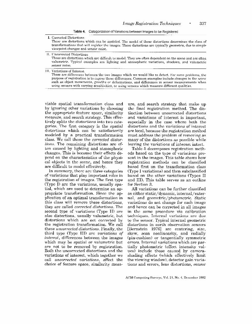
Image Registration Techniques ● 337
Table 4. Categorlzatlon of Varlatlons between Images to be Registered
I. Corrected DistortionsThese are distortions which can be modeled. The model of these distortions determines the class oftransformations that will register the images. These distortions are typical~y geometric, due to simpleviewpoint changes and sensor noise.
II. Uncorrected DistortionsThese are distortions which are difficult to model. They are often dependent on the sceneand are oftenvolumetric. Typical examples are lighting and atmospheric variations, shadows, and volumetricsensor noise.
III. Variations of InterestThese are differences between the two images which we would like to detect. For some problems, thepurpose of registration is to expose these differences. Common examples include changes in the scenesuch as object movements, growths or deformations, and differences in sensor measurements whenusing sensors with varying sensitivities, or using sensors which measure different qualities.
viable spatial transformation class andby ignoring other variations by choosingthe appropriate feature space, similaritymeasure, and search strategy. This effec-tively splits the distortions into two cate-gories. The first category is the spatialdistortions which can be satisfactorilymodeled by a practical transformationclass. We call these the corrected distor-
tions. The remaining distortions are of-ten caused by lighting and atmosphericchanges. This is because their effects de-pend on the characteristics of the physi-cal objects in the scene, and hence theyare difficult to model effectively.
In summary, there are three categoriesof variations that play important roles inthe registration of images. The first type
(Type I) are the variations, usually spa-tial, which are used to determine an ap-propriate transformation. Since the ap-plication of an optimal transformation inthis class will remove these distortions,they are called corrected distortions. Thesecond type of variations (Type II) arealso distortions, usually volumetric, butdistortions which are not corrected bythe registration transformation. We callthese uncorrected distortions. Finally, thethird type (Type III) are variations of
interest, differences between the imageswhich may be spatial or volumetric butare not to be removed by registration.Both the uncorrected distortions and thevariations of interest, which together wecall uncorrected variations, affect thechoice of feature space, similarity me as-
ure, and search strategy that make upthe final registration method. The dis-tinction between uncorrected distortionsand variations of interest is important,especially in the case where both thedistortions and the variations of interestare local, because the registration methodmust address the problem of removing asmany of the distortions as possible whileleaving the variations of interest intact.
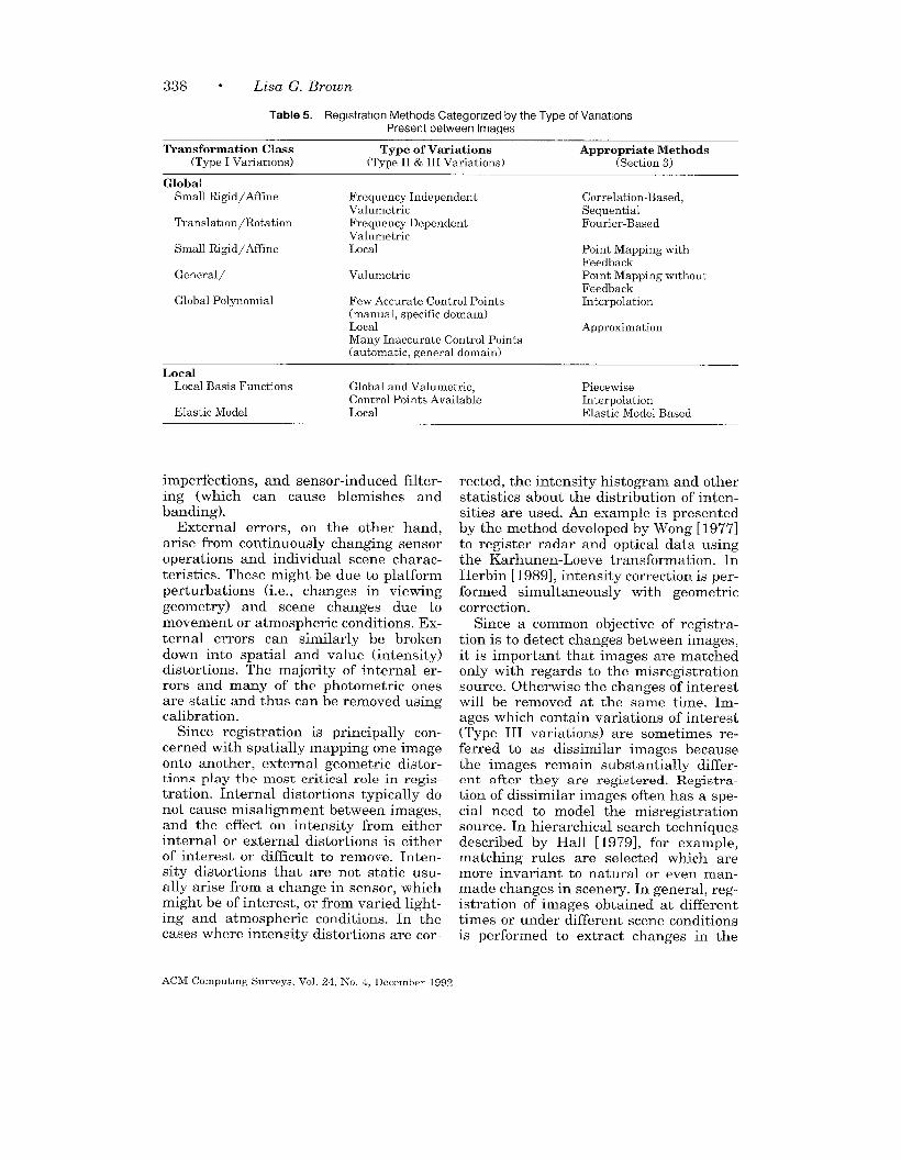
Table 5 decomposes registration meth-ods based on the type of variations pre-sent in the images. This table shows howregistration methods can be classifiedbased first on the transformation class(Type I variations) and then subclassifiedbased on the other variations (Types IIand III). This table serves as an outlinefor Section 3.
All variations can be further classifiedas either static/dynamic, internal/exter-nal, and geometric\ photometric. Staticvariations do not change for each imageand hence can be corrected in all imagesin the same procedure via calibrationtechniques. Internal variations are dueto the sensor. Typical internal geometricdistortions in earth observation sensors[Bernstein 1976] are centering, size,skew, scan nonlinearity, and radially(pin-cushion) or tangentially symmetricerrors. Internal variations which are par-tially photometric (effect intensity val-ues) include those caused by camera-shading effects (which effectively limitthe viewing window), detector gain varia-tions and errors, lens distortions, sensor
ACM Computing Surveys,Vol. 24, No. 4, December1992
338 ● Lisa G. Brown
Table 5. Reglstratlon Methods Categorized by the Type of VariationsPresent between Images
Transformation Class Type of Variations Appropriate Methods
(Type I Variations) (Type II & III Variations) (Section 3)
GlobalSmall Rigid/Affine Frequency Independent Correlation-Based,
Volumetric SequentialTranslation/Rotation Frequency Dependent Fourier-Based
Small R@d\Aftine
General/
Global Polynomial
VolumetricLocal Point Mapping with
FeedbackVolumetric Point Mapping without
FeedbackFew Accurate Control Points Interpolation(manual, specific domam)Local ApproximationMany Inaccurate Control Points(automatic, general domain)
LocalLocal Basis Functions Global and Volumetric, Piecewise
Control Points Available InterpolationElastlc Model Local Elastic Model Based
imperfections, and sensor-induced filter-ing (which can cause blemishes andbanding).
External errors, on the other hand,arise from continuously changing sensoroperations and individual scene charac-teristics. These might be due to platformperturbations (i.e., changes in viewinggeometry) and scene changes due tomovement or atmospheric conditions. Ex-ternal errors can similarly be brokendown into spatial and value (intensity)distortions. The majority of internal er-rors and many of the photometric onesare static and thus can be removed usingcalibration.
Since registration is principally con-cerned with spatially mapping one imageonto another, external geometric distor-tions play the most critical role in regis-tration. Internal distortions typically donot cause misalignment between images,and the effect on intensity from eitherinternal or external distortions is eitherof interest or difficult to remove. Inten-sity distortions that are not static usu-ally arise from a change in sensor, whichmight be of interest, or from varied light-ing and atmospheric conditions. In thecases where intensity distortions are cor-
rected, the intensity histogram and otherstatistics about the distribution of inten-sities are used. An example is presentedby the method developed by Wong [ 1977]to register radar and optical data usingthe Karhunen-Loeve transformation. InHerbin [1989], intensity correction is per-formed simultaneously with geometriccorrection.
Since a common objective of registra-tion is to detect chamzes between images,it is important that ~mages are matc~edonly with regards to the misregistrationsource. Otherwise the changes of interestwill be removed at the same time. Im-ages which contain variations of interest
(Type III variations) are sometimes re-ferred to as dissimilar images becausethe images remain substantially differ-ent after they are registered. Registra-tion of dissimilar images often has a spe-cial need to model the misregistrationsource. In hierarchical search techniquesdescribed by Hall [1979], for example,matching rules are selected which aremore invariant to natural or even man-made changes in scenery. In general, reg-istration of images obtained at differenttimes or under different scene conditionsis performed to extract changes in the
ACM Computmg Surveys, Vol. 24, No. 4, December 1992
Image Registration Techniques “ 339
scene. Examples are the detection of thegrowth of urban developments in aerialphotography or of tumors in mammog-rams. Registration of images acquiredfrom different sensors integrates the dif-ferent measurements in order to classifypicture points for segmentation (wherebyregions of the image can be found thatcorrespond to meaningful objects in thescene) and for object recognition (so thatthese regions can be labeled according towhat they correspond to in the scene). Inboth these instances, of multimodal ortemporal registration, variations existwhich are not to be removed by registra-tion. This presents additional constraintson matching which must find similaritiesin the face of irrelevant variations.
Not surprisingly, the more that isknown about the type of distortions pres-ent in a particular system, the more ef-fective registration can be. For example,Van Wie [1977] decomposes the errorsources in Landsat multispectral im-agery into those due to sensor operation,orbit and altitude anomalies, and earthrotation. Errors are also categorized asglobal continuous, swath continuous, orswath discontinuous. Swath errors areproduced by differences between sweepsof the sensor mirror in which only a cer-tain number of scan lines are acquired.This decomposition of the sources of mis-registration is used in the generation of aregistration system with several special-ized techniques which depend on the ap-plication and classes of distortions to berectified. For example, a set of controlpoints can be used to solve an altitudemodel, and swath errors can be correctedindependent of other errors, thus reduc-ing the load of the global corrections andimproving performance.
In computer vision, images with differ-ent viewing geometries, such as stereoimage pairs, are “registered” to deter-mine the depth of objects in the scene ortheir three-dimensional shape character-istics. Surveys in stereomapping includeBarnard and Fischler [ 1982] and Dhondand Aggarwal [1989]. This requiresmatching features in the images andfinding the disparity between them; this
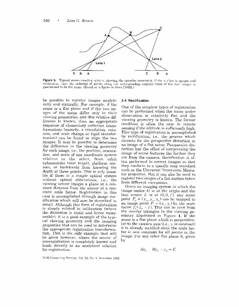
is often called the correspondence prob-lem. In this case, the majority of thevariations are corrected by the mappingbetween images, but on the other handthe resulting mapping is highly complex.Consider the problems of occlusion, thedifferent relative position of imaged ob-jects and the complete unpredictability ofthe mapping because of the unknowndepths and shapes of objects in the scene.Hence, problems of stereo matching andmotion tracking alsc} have a real need tomodel the source of misregistration. Byexploiting camera and object model char-acteristics such as viewing geometry,smooth surfaces, and small motions,these registration-like techniques be-come very specialized. For example, instereomapping, images differ by theirimaging viewpoint, and therefore thesource of misregistration is due to differ-ences in perspective. This greatly re-duces the possible transformations andallows registration methods to exploit theproperties of stereo imagery. Because ofthe geometry imposed by the cameraviewpoints, the location of any point inone image constrains the location of thepoint in the other image (which repre-sents the same point in the 3D scene) toa line. This is called the epipolar con-straint, and the line in which the match-ing point must lie is called the epipolarline. If the surfaces in the scene areopaque, continuous and if their scanlines(the rows of pixels in the image) are par-allel to the baseline (the line connectingtheir two viewpoints), then an orderingconstraint is also ilmposed along corre-sponding epipolar lines. See Figure 5.Furthermore, the gradient of the dispar-ity (the change in the difference in posi-tion between the two images of a pro-jected point) is directly related to thesmoothness of surfaces in the scene. Byusing these constraints instead of lookingfor an arbitrary transformation with ageneral registration method, the stereocorrespondence problem can be solvedmore directly, i.e., search is more effi-cient and intelligent.
When sufficient information about themisregistration source is available, it may
ACM Computmg Surveys, Vol. 24, No. 4, December 1992
340 “ Lisa G. Brown
CBA c BA
Figure 5. Typical stereo Imaging system, showing the eplpolar constraint If the surface m opaque andcontinuous. then the ordering of points along the corresponding epipolar lines of the two images Mguaranteed to be the same (Based on a figure m Horn [1989].)
be possible to register images analyti-cally and statically. For example, if thescene is a flat plane and if the two im-ages of the scene differ only in theirviewing geometries, and this relative dif-ference is known, then an appropriatesequence of elementary cartesian trans-formations (namely, a translation, rota-tion, and scale change or rigid transfor-mation) can be found to align the twoimages. It may be possible to determinethe difference in the viewing geometryfor each image, i.e., the position, orienta-tion, and scale of one coordinate system
relative to the other, from orbitephemerides (star maps), platform sen-sors, or backwards from knowing thedepth at three points. This is only possi-ble if there is a simple optical systemwithout optical abberations, i.e., theviewing sensor images a plane at a con-stant distance from the sensor at a con-stant scale factor. Registration in thiscase is accomplished through image rec-tification which will now be described indetail. Although this form of registrationis closely related to calibration (wherethe distortion is static and hence meas-urable), it is a good example of the typi-cal viewing geometry and the imagingproperties that can be used to determinethe appropriate registration transforma-tion. This is the only example that willbe given however, where the source ofmisregistration is completely known andleads directly to an analytical solutionfor registration.
2.4 Rectification
One of the simplest types of registrationcan be performed when the scene underobservation is relatively flat and theviewing geometry is known. The formercondition is often the case in remotesensing if the altitude is sufficiently high.This type of registration is accomplished
by rectification, i.e., the process whichcorrects for the perspective distortion inan image of a flat scene. Perspective dis-tortion has the effect of compressing theimage of scene features the farther theyare from the camera. Rectification is of-ten performed to correct images so thatthey conform to a specific map standardsuch as the Universal Transverse Merca-tor projection. But it can also be used toregister two images of a flat surface takenfrom different viewpoints.
Given an imaging system in which theimage center O is at the origin and thelens center L is at (O, O, f), any scenepoint PO = (xO, yO, z“) can be mapped toan image point P, = ( xl, y,) by the scalefactor f/( 20 – f’). This can be seen fromthe similar triangles in the viewing ge-ometry illustrated in Figure 4. If thescene is a flat plane which is perpendicu-lar to the camera axis (i.e., z is constant)it is already rectified since the scale fac-tor is now constant for all points in theimage. For any other flat plane S, givenby
AxO+Byfl+zO=C
ACM Computmg Surveys, Vol 24, No 4. December 1992

Image Registration Techniques . 341
Y I
Figure 6. Any plane can be decomposed into lines parallel to the image plane.
where A, B, and C are constants, rectifi-cation can be performed by mapping theintensity of the image point at (x,, y,)into the new rectified image point loca-tion (/i,\Z, ~yZ/Z) where Z = ~ -- Ax, –By, [Rosenfeld 1982]. This is because thescene plane can be decomposed into linesAx. + ByO = C‘ each at a constant dis-tance ( ZO = C – C‘ ) from the imageplane. Each line then maps to a line inthe image plane, and since its perspec-tive distortion is related to its distancefrom the image, all points on this linemust be scaled accordingly by f/(C – C‘– ~). Figure 6 shows how a plane is de-composed into lines that are each paral-lel to the image plane.
Two pictures of the flat plane takenfrom different viewpoints can be regis-tered by the following steps. First, thescene coordinates (xl, yl, ZI) are relatedto their image coordinates in image 1 of apoint with respect to camera 1 by a scale
factor (Z1 – f)/f dependent on theirdepth (the .zI coordinate) and the lenscenter f because of similar triangles. Thisgives us two equations. Since they mustalso satisfy the equation of the plane, wehave three equations from which we canderive the three coordinates of each scenepoint using its corresponding image point
with respect to coordinate system of cam-era 1. The scene coordinates are thenconverted from the coordinate systemwith respect to camera 1 to a coordinatesystem with respect to camera 2 to ob-tain (xz, yz, Zz). Lastly, these can be pro-jected onto image 2 by the factor ~/( Zz –f), again by similar triangles. Of course,if these are discrete images, there is stillthe problem of interpolation if the regis-tered points do not fall on grid locations.See Wolberg [1990] for a good survey ofinterpolation methods.
3. REGISTRATION METHODS
3.1 Correlation and Sequential Methods
Cross-correlation is the basic statisticalapproach to registration. If is often usedfor template matching or pattern recog-nition in which the location and orienta-tion of a template or pattern is found in apicture. By itself, cross-correlation is nota registration method. It is a similaritymeasure or match metric, i.e., it gives ameasure of the degree of similarity be-tween an image and a template. How-ever, there are several registration meth-ods for which it is the primary tool, andit is these methods and the closely re-
ACM Computing Surveys,Vol. 24, No. 4, December1992

342 ● Lisa G. Brown
lated sequential methods which are dis-cussed in this section. These methods aregenerally useful for images which aremisaligned by small rigid or afflnetransformations.
For a template T and image 1, where T
is small compared to I, the two-dimer.-sional normalized cross-correlation func-tion measures the similarity for eachtranslation:
realize, as before, using the local imageenergy XX ZY12(X – u, y – v). Noticethat if you expand this intuitive measureD(u, v) into its quadratic terms, thereare three terms: a template energy term,a product term of template and image,and an image energy term. It is the prod-uct term or correlation Z1 Z ,7’( x, y )1(x—
Zf, Y — ~) which when nonmzdized, de.termmes the outcome of this measure.
ZXZYT(X, Y) I(-Y– U,y – U) A related measure, which is advan-
C(u, v) =
J[
tageous when an absolute measureZ1XY12(Z - U,y - u)] “ needed, is the correlation coefficient
is
where M, and cr. are mean and stan-
If the template matches the image ex-actly, except for an intensity scale factor,at a translation of (i, ~“), the cross-corre-lation will have its peak at C(i, j). (SeeRosenfeld and Kak [1982] for a proof ofthis using the Cauchy-Schwarz inequal-ity.) Thus, by computing C over all pos-sible translations, it is possible to findthe degree of similarity for anytemplate-sized window in the image. No-tice the cross-correlation must be nor-malized since local image intensity wouldotherwise influence the measure.
The cross-correlation measure is di-rectly related to the more intuitive mea-sure which computes the sum of the dif-ferences squared between the templateand the picture at each location of thetemplate:
D(u, IJ)=~~(T(x, y)
x “v
I(x–zL>y–u))2.
This measure decreases with the degreeof similarity since, when the template isplaced over the picture at the location( Z1,u) for which the template is most simi-lar, the differences between the corre-sponding intensities will be smallest. Thetemplate energy defined as XX ZYTZ( x, y)
is constant for each position (u, u ) thatwe measure. Therefore. we should nor-
dard d~~iation of the template and PIand crI are mean and standard deviationof the image.1 This statistical measurehas the property that it measures corre-lation on an absolute scale ranging from[ – 1, 1]. Under certain statistical as-sumptions, the value measured by thecorrelation coefficient gives a linear indi-cation of the similarity between images.This is useful in order to quantitativelymeasure confidence or reliability in amatch and to reduce the number of mea-surements needed when a prespecifiedconfidence is sufficient [Svedlow et al.1976] .
Consider a simple example of a binaryimage and binary template, i.e., all thepixels are either black or white, for whichit is possible to predict with some proba-bility whether or not a pixel in the imagewill have the same binary value as apixel in the template. Using the correla-tion coefficient, it is possible to computethe probability or confidence that the im-age is an instance of the template. Weassume the template is an ideal repre-
1The mean p of an image is the average intensityvalue; if the image I M defined over a region x =1, N, y = 1, M then PI = ~~.l~~.l(z(x, y)/(NY M )). The standard deviation is a measure ofthe varlatlon there in the intensity values. It isdefined as WIJ = X!. ~X~l. ~((l(.z, y) –&r) ’/’(Iv - M)).
ACM Computing Surveys, Vol 24, No 4. December 1992

Image Registration Techniques ● 343
sentation of the pattern we are lookingfor. The image may or may not be aninstance of this pattern. However, if wecan statistically characterize the noisethat has corrupted the image, then thecorrelation coefficient can be used toquantitatively measure how likely it isthat the image is an instance of thetemplate.
Another useful property of correlationis given by the Correlation theorem. TheCorrelation theorem states that theFourier transform of the correlation oftwo images is the product of the Fouriertransform of one image and the complexconjugate of the Fourier transform of theother. This theorem gives an alternateway to compute the correlation betweenimages. The Fourier transform is simplyanother way to represent the image func-tion. Instead of representing the imagein the spatial domain, as we normally do,the Fourier transform represents thesame information in the frequency do-main. Given the information in one do-main we can easily convert to the otherdomain. The Fourier transform is widelyused in many disciplines, both in caseswhere it is of intrinsic interest and as atool, as in this case. It can be computedefficiently for images using the FastFourier Transform or FFT. Hence, animportant reason why the correlationmetric is chosen in many registrationproblems is because the Correlation theo-rem enables it to be computed efficiently,with existing, well-tested programs usingthe FFT (and occasionally in hardwareusing specialized optics). The use of theFFT becomes most beneficial for caseswhere the image and template to betested are large. However there are twomajor caveats. Only the cross-correlationbefore normalization may be treated byFFT. Second, although the FFT is fasterit also requires a memory capacity thatgrows with the log of the image area.Last, both direct correlation and correla-tion using FFT have costs which grow atleast linearly with the image area.
Solving registration problems like tem-plate matching using correlation hasmany variations [Pratt 1978]. Typically
the cross-correlation between the imageand the template (or one of the relatedsimilarity measures given above) is com-puted for each allowable transformationof the template. The transformationwhose cross-correlation is the largestspecifies how the template can be opti-mally registered to the image. This isthe standard approach when the allow-able transformations include a smallrange of translations, rotations, and scalechanges; the template is translated, ro-tated, and scaled for each possible trans-lation, rotation, and scale of interest. Asthe number of transformations grows,however, the computational costs quicklybecome unmanageable. This is the rea-son that the correlation methods are gen-erally limited to registration problems inwhich the images are misaligned only bya small rigid or affine transformation. Inaddition, to reduce the cost of each meas-urement for each transformation in-stance, measures are often computed onfeatures instead of the whole image area.Small local features of the template whichare more invariant to shape and scale,such as edges joined in a Y or a T, arefrequently used.
If the image is noisy, i.e., there aresignificant distortions which cannot beremoved by the transformation, the peakof the correlation may not be clearly dis-cernible. The Matched Filter Theoremstates that for certain types of noise suchas additive white noise, the cross-correlation filter that maximizes the ra-tio of signal power to the expected noisepower of the image, i.e., the informationcontent, is the ternplate itself. In othercases however, the image must be pre-filtered before crow-correlation to main-tain this property. The prefilter and thecross-correlation fillter (the template) canbe used to produce a single filter whichcan simultaneously perform both filter-ing operations. The prefilter to be usedcan sometimes be determined if the noisein the image satisfies certain statisticalproperties. These techniques, which pre-filter based on the properties of the noiseof the image in order to maximize thepeak correlation with respect to this noise
ACM Computmg Surveys. Vol. 24, No 4, December 1992

344 “ Lisa G. Brown
(using the Matched Filter Theorem) andthen cross-correlate, are called matched
filter techniques [Rosenfeld and Kak1982]. The disadvantages of these tech-niques are that they can be computation-ally intensive, and in practice the statis-tical assumptions about the noise in theimage are difficult to satisfy.
A far more efficient class of algorithmsthan traditional cross-correlation, calledthe sequential similarity detection algo-rithms (SSDAS), was proposed by Barneaand Silverman [1972]. Two major im-provements are offered. First, they sug-gest a similarity measure IN u, v), whichis computationally much simpler, basedon the absolute differences between thepixels in the two images,
E(2L, V) = ~ ~lT(x, y)
XY
–I(x–u, y–v)l.
The normalized measure is defined as
E(u, u)= ~~lT(x,y) –Yx Y
–I(x–u, y–v)+i(u, v)l
A Awhere T and I are the average intensi-ties of the template and local image win-dow respectively. This is significantlymore efficient than correlation. Correla-tion requires both normalization and theadded expense of multiplications. Even ifthis measure is unnormalized a mini-mum is guaranteed for a perfect match.Normalization is useful, however, to getan absolute measure of how the two im-ages differ, regardless of their intensityscales.
The second improvement Barnea andSilverman [ 1972] introduce is a sequen-tial search strategy. In the simplest caseof translation registration this strategymight be a sequential thresholding. Foreach window of the image (determined bythe translation to be tested and the tem-plate size), one of the similarity meas-ures defined above is accumulated untilthe threshold is exceeded. For each win-dow the number of points that were ex-amined before the threshold was ex-
ceeded is recorded. The window whichexamined the most points is assumed tohave the lowest measure and is thereforethe best registration.
The sequential technique can signifi-cantly reduce the computational com-plexity with minimal performance degra-dation. There are also many variationsthat can be implemented in order to adaptthe method to a particular set of imagesto be registered. For example, an order-ing algorithm can be used to order thewindows tested which may depend onintermediate results, such as a coarse-to-!iine search or a gradient technique.These strategies will be discussed in moredetail in Section 4.3. The ordering of thepoints examined during each test can alsovary depending on critical features to betested in the template. The similaritymeasure and the sequential decision al-gorithm might vary depending on the re-quired accuracy, acceptable speed, andcomplexity of the data.
Although the sequential methods im-prove the efficiency of the similaritymeasure and search, they still have in-creasing complexity as the degrees offreedom of the transformation is in-creased. As the transformation becomesmore general the size of the search grows.On the one hand, sequential search be-comes more important in order to main-tain reasonable time complexity; on theother hand it becomes more difficult notto miss good matches.
In comparison with correlation, the se-quential similarity technique improvesefficiency by orders of magnitude. Testsconducted by Barnea and Silverman[1972], however, also showed differencesin results. In satellite imagery taken un-der bad weather conditions, cloudsneeded to be detected and replaced withrandom noise before correlation wouldyield a meaningful peak. Whether thedifferences found in their small studycan be extended to more general casesremains to be investigated.
A limitation of both of these methods istheir inability to deal with dissimilar im-ages. The similarity measures describedso far, the correlation coefficient, and the
ACM Computmg Surveys, Vol 24, No 4, December 1992
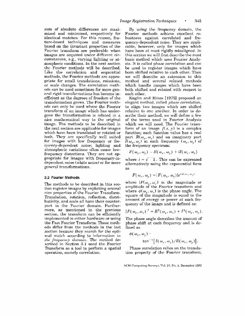
Image Registration Techniques ● 345
sum of absolute differences are maxi-mized and minimized, respectively foridentical matches. For this reason, fea-ture-based techniques and measuresbased on the invariant properties of theFourier transform are preferable whenimages are acquired under different cir-cumstances, e.g., varying lighting or at-mospheric conditions. In the next sectionthe Fourier methods will be described.Like the correlation and sequentialmethods, the Fourier methods are appro-priate for small translations, ro~ations,or scale changes. The correlation meth-ods can be used sometimes for more gen-eral rigid transformations but become in-efficient as the degrees of freedom of thetransformation grows. The Fourier meth-ods can only be used where the Fouriertransform of an image which has under-gone the transformation is related in anice mathematical way to the originalimage. The methods to be described inthe next section are applicable for imageswhich have been translated or rotated orboth. They are specifically well suitedfor images with low frequency or fre-quency-dependent noise; lighting andatmospheric variations often cause low-frequency distortions. They are not ap-propriate for images with frequency-in-dependent noise (white noise) or for moregeneral transformations.
3.2 Fourier Methods
The methods to be described in this sec-tion register images by exploiting severalnice properties of the Fourier Transform.Translation, rotation, reflection, distri-butivity, and scale all have their counter-part in the Fourier domain. Further-more, as mentioned in the previoussection, the transform can be efficientlyimplemented in either hardware or usingthe Fast Fourier Transform. These meth-ods differ from the methods in the lastsection because they search for the opti-mal match according to information inthe frequency domain. The method de-scribed in Section 3.1 used the FourierTransform as a tool to perform a spatialoperation, namely correlation.
By using the frequency domain, theFourier methods achieve excellent ro-bustness against correlated and fre-quency-dependent noise. They are appli-cable, however, only for images whichhave been at most rigidly misaligned. Inthis section we will first describe the mostbasic method which uses Fourier Analy-sis. It is called phase correlation and canbe used to register images which havebeen shifted relative to each other. Thenwe will describe an extension to thismethod and several related methodswhich handle images which have beenboth shifted and rotated with respect toeach other.
Kuglin and Hines [1975] proposed anelegant method, called phase correlation,
to align two images which are shiftedrelative to one another. In order to de-scribe their method, we will define a fewof the terms used in Fourier Analysiswhich we will need. The Fourier trans-form of an image f( x, y) is a complexfunction; each function value has a realpart R( OJx, OY ) and an imaginary part1( w., COY)at each frequency (a,, OY) ofthe frequency spectrum:
F’(OX, COY)=R(WI1, COY) + i~(~l, WY)
where i = ~. This can be expressedalternatively using the exponential formas
F(@x, @y) =lq@.!@Y )Iel+(%!%)
where IF( ox, Oy )1 is the magnitude oramplitude of the Fourier transform andwhere @(co., tiY ) is the phase angle. Thesquare of the magnitude is equal to theamount of energy or power at each fre-quency of the image and is defined as:
lw%@.v)lz= P’(ox, tiy) +~2(@.7 @Y)
The phase angle describes the amount ofphase shift at each frequency and is de-fined as
@(@x, @Y)=
tan-l [~(co,, @Y)/R( @x, @Y)].
Phase correlation relies on the transla-tion property of the Fourier transform,
ACM Computing Surveys,Vol. 24, No. 4, December1992
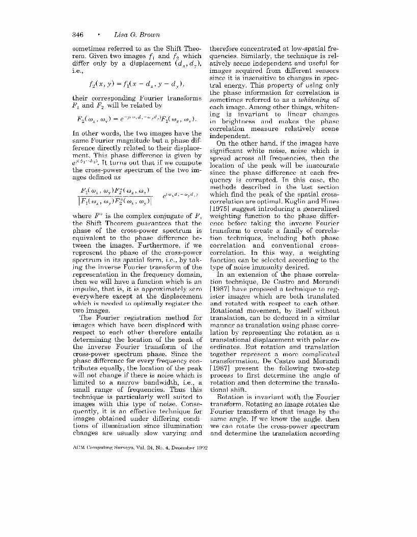
346 ● Lisa G. Brown
sometimes referred to as the Shift Theo-rem. Given two images fl and fz whichdiffer only by a displacement (d%, dj ),i.e.,
f,(x, y) =f,(x -dz, y -d,),
their corresponding Fourier transformsPI and Fz will be related by
In other words, the two images have thesame Fourier magnitude but a phase dif-ference directly related to their displace-ment. This phase difference is given by@ 41– ~ z), It turns out that if we compute
the cross-power spectrum of the two im-ages defined as
where F* is the complex conjugate of F,
the Shift Theorem guarantees that thephase of the cross-power spectrum isequivalent to the phase difference be-tween the images. Furthermore, if werepresent the phase of the cross-powerspectrum in its spatial form, i.e., by tak-ing the inverse Fourier transform of therepresentation in the frequency domain,then we will have a function which is animpulse, that is, it is approximately zeroeverywhere except at the displacementwhich is needed to optimally register thetwo images.
The Fourier registration method forimages which have been displaced withrespect to each other therefore entailsdetermining the location of the peak ofthe inverse Fourier transform of thecross-power spectrum phase, Since thephase difference for every frequency con-tributes equally, the location of the peakwill not change if there is noise which islimited to a narrow bandwidth, i.e., asmall range of frequencies. Thus thistechnique is particularly well suited toimages with this type of noise. Conse-quently, it is an effective technique forimages obtained under differing condi-tions of illumination since illuminationchanges are usually slow varying and
therefore concentrated at low-spatial fre-quencies. Similarly, the technique is rel-atively scene independent and useful forimages acquired from different sensorssince it is insensitive to changes in spec-tral energy. This property of using onlythe phase information for correlation issometimes referred to as a whitening ofeach image. Among other things, whiten-ing is invariant to linear changesin brightness and makes the phasecorrelation measure relatively sceneindependent.
On the other hand, if the images havesignificant white noise, noise which isspread across all frequencies, then thelocation of the peak will be inaccuratesince the phase difference at each fre-quency is corrupted. In this case, themethods described in the last sectionwhich find the peak of the spatial cross-correlation are optimal. Kuglin and Hines[ 1975] suggest introducing a generalizedweighting function to the phase differ-ence before taking the inverse Fouriertransform to create a family of correla-tion techniques, including both phasecorrelation and conventional cross-correlation. In this way, a weightingfunction can be selected according to thetype of noise immunity desired.
In an extension of the phase correla-tion technique, De Castro and Morandi[ 1987] have proposed a technique to reg-ister images which are both translatedand rotated with respect to each other.Rotational movement, by itself withouttranslation, can be deduced in a similarmanner as translation using phase corre-lation by representing the rotation as atranslational displacement with polar co-ordinates. But rotation and translationtogether represent a more complicatedtransformation. De Castro and Morandi[ 1987] present the following two-stepprocess to first determine the angle ofrotation and then determine the transla-tional shift.
Rotation is invariant with the Fouriertransform. Rotating an image rotates theFourier transform of that image by thesame angle. If we know the angle, thenwe can rotate the cross-power spectrumand determine the translation according
ACM Comput]ng Surveys, Vol. 24, No. 4, December 1992

Image Registration Techniques ● 347
to the phase correlation method. How-ever, since we do not know the angle, wecompute the phase of the cross-powerspectrum as a function of the rotationangle estimate ~ and use polar coordi-nates (r, 0) to simplify the equation. Thisgives us a function
which at the true angle of rotation shouldhave the form expected for images whichhave only been translated. Therefore,by first determining the angle @ whichmakes the inverse Fourier transform ofthe phase of the cross-power spectrumthe closest approximation to an impulse,we can then determine the translation asthe location of this pulse.
In implementing the above method, itshould be noted that some form of inter-polation must be used to find the valuesof the transform after rotation since theydo not naturally fall in the discrete grid.Although this might be accomplished bycomputing the transform after first rotat-ing in the spatial domain, this would betoo costly. De Castro and Morandi [1987]applied the transform to a zero-paddedimage thus increasing the resolution andimproving the approximation of thetransform after rotation. The method isalso costly because of the difficulty intesting for each ~. Alliney and Morandi[1986] presented a method which onlyrequires one-dimensional Fourier trans-formations to compute the phase correla-tion. By using the x- and y-projections ofeach image, the Fourier transforms aregiven by the projection slice theorem. ThelD transform of the x- and y-projectionsis simply the row of the 2D transformwhere w ~ = O and the column where coY= O respectively. Although substantialcomputational savings are gained, themethod is no longer robust except forrelatively small translations.
The Fourier methods, as a class, offeradvantages in noise sensitivity and com-putational complexity. Lee et al. [1987]developed a similar technique which usesthe power cepstrum of an image (thepower spectrum of the logarithm of the
power spectrum) to register images forthe early detection of glaucoma. First theimages are made parallel by determiningthe angle which minimizes the differ-ences in their power spectra (whichshould theoretically be zero if there isonly a translational shift between them).Then the power spectrum is used to de-termine the translational correspondencein a similar manner to phase correlation.This has the advantage over De Castroand Morandi [1987] of the computationalsavings gained by adding images insteadof multiplying them due to the use oflogarithms. The work of De Castro andMorandi [1987’] summarizes previouswork published in Italy before 1987, butno direct comparison with Lee et al.
[19$71 has yet been undertaken. Bothmethods achieve better accuracy and ro-bustness than the primary methods men-tioned in Section 3.1 and for less compu-tational time than classical correlation.However, because the Fourier methodsrely on their invariant properties, theyare only applicable for certain well-de-fined transformations such as rotationand translation. In the following sectiona more general technique is describedbased on a set of matched control points.These techniques can be used for arbi-trary transformations including polyno-mial and piecewise local. Furthermore,even in the case of a small rigid transfor-mation, it is not always possible to regis-ter images using the techniques de-scribed so far. If there exists a significantamount of spatially local variation (eventhough the misalignment is only due to asmall -igid transformation), then the cor-relation and Fourier techniques breakdown. The sophisticated use of featuredetection can help to overcome some ofthese local variations, but in Section 3.3.2we will introduce th e more powerfulmethods which use point mapping withfeedback in order to tolerate these typesof variations.
3.3 Point Mapping
The point- or landmark-mapping tech-nique is the primary approach currentlytaken to register two images whose type
ACM Computmg Surveys, Vol. 24, No 4, December 1992
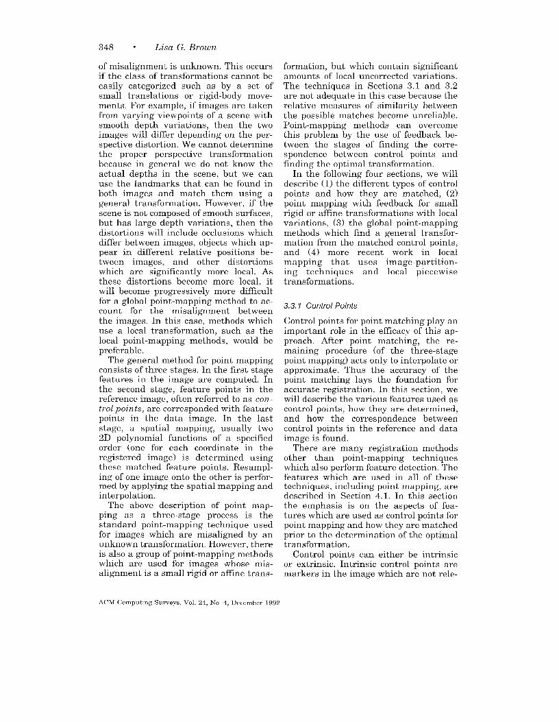
348 ● Lisa G. Brown
of misalignment is unknown. This occursif the class of transformations cannot beeasily categorized such as by a set ofsmall translations or rigid-body move-ments. For example, if images are takenfrom varying viewpoints of a scene withsmooth depth variations, then the twoimages will differ depending on the per-spective distortion. We cannot determinethe proper perspective transformationbecause in general we do not know theactual depths in the scene, but we canuse the landmarks that can be found inboth images and match them using ageneral transformation. However, if thescene is not composed of smooth surfaces,but has large depth variations, then thedistortions will include occlusions whichdiffer between images, objects which ap-pear in different relative positions be-tween images, and other distortionswhich are significantly more local. Asthese distortions become more local, itwill become progressively more difficultfor a global point-mapping method to ac-count for the misalignment betweenthe images. In this case, methods whichuse a local transformation, such as thelocal point-mapping methods, would bepreferable.
The general method for point mappingconsists of three stages. In the first stagefeatures in the image are computed. Inthe second stage, feature points in thereference image, often referred to as con-
trol points, are corresponded with featurepoints in the data image. In the laststage, a spatial mapping, usually two2D polynomial functions of a specifiedorder (one for each coordinate in theregistered image) is determined usingthese matched feature points. Resampl-ing of one image onto the other is perfor-med by applying the spatial mapping andinterpolation.
The above description of point map-ping as a three-stage process is thestandard point-mapping technique usedfor images which are misaligned by anunknown transformation. However, thereis also a group of point-mapping methodswhich are used for images whose mis-alignment is a small rigid or affine trans-
formation, but which contain significantamounts of local uncorrected variations.The techniques in Sections 3.1 and 3.2are not adequate in this case because therelative measures of similarity betweenthe possible matches become unreliable.Point-mapping methods can overcomethis problem by the use of feedback be-tween the stages of finding the corre-spondence between control points andfinding the optimal transformation.
In the following four sections, we willdescribe (1) the different types of controlpoints and how they are matched, (2)point mapping with feedback for smallrigid or affine transformations with localvariations, (3) the global point-mappingmethods which !ikd a general transfor-mation from the matched control points,and (4) more recent work in localmapping that uses image-partition-ing techniques and local piecewisetransformations.
3.3.1 Control Points
Control points for point matching play animportant role in the efficacy of this ap-proach. After point matching, the re-maining procedure (of the three-stagepoint mapping) acts only to interpolate orapproximate. Thus the accuracy of thepoint matching lays the foundation foraccurate registration. In this section, wewill describe the various features used ascontrol points, how they are determined,and how the correspondence betweencontrol points in the reference and dataimage is found.
There are many registration methodsother than point-mapping techniqueswhich also perform feature detection. Thefeatures which are used in all of thesetechniques, including point mapping, aredescribed in Section 4.1. In this sectionthe emphasis is on the aspects of fea-tures which are used as control points forpoint mapping and how they are matchedprior to the determination of the optimaltransformation.
Control points can either be intrinsicor extrinsic. Intrinsic control points aremarkers in the image which are not rele-
ACM Computmg Surveys, Vol. 24, No 4, December 1992

Image Registration Techniques ● 349
vant to the data itself. They are oftenplaced in the scene specifically for regis-tration purposes and are easily identi-fied. If marks are placed on the sensor,such as reseau marks which are smallcrossbars inscribed on the faceplate ofthe sensor, then they aid registration in-sofar as they independently calibrateeach image according to sensor distor-tions. In medical imaging, identifiablestructures, called fiducial markers, areplaced in known positions in the patientsto act as reference points. In magneticresonance imaging (MRI) systems [Evanset al. 1988], chemical markers, such asplastic N-shaped tubing filled withCw5’Od, are strategically placed to assistin registration. In positron emission to-mography (PET) [Bergstrom et al. 1981;Bohm et al. 1983; Bohm and Greitz 1988;Fox et al. 1985] stereotactic coordinateframes are used so that a three-dimen-sional coordinate reference frame can beidentified. Although intrinsic controlpoints are preferable for obvious reasons,there are not always intrinsic points thatcan be used. For example, precisely plac-ing markers internally is not always pos-sible in diagnostic images [ Singh et al.1979].
Control points that are extrinsic aredetermined from the data, either manu-ally or automatically. Manual controlpoints, i.e., points recognized by humanintervention, such as identifiable land-marks or anatomical structures, haveseveral advantages. Points can be se-lected which are known to be rigid, sta-tionary, and easily pin-pointed in bothdata sets. Of course, they require some-one who is knowledgeable in the domain.In cases where there is a large amount ofdata this is not feasible. Therefore manyapplications use automatic location ofcontrol points. Typical features that areused are corners, line intersections,points of locally maximum curvature oncontour lines, centers of windows havinglocally maximum curvature, and centersof gravity of closed-boundary regions[Goshtasby 1988]. Features are selectedwhich are likely to be uniquely found inboth images (a more delicate issue when
using multisensory data) and more toler-ant of local distortions. Since computingthe proper transformation depends onthese features, a sufficient number mustbe detected to perform the calculation.On the other hand too many features willmake feature matching more difficult.The number of features to use becomes acritical issue since both the accuracy andthe efficiency of point-matching methodswill be strongly influenced. This will bediscussed in more detail in Section 3.3.3for the case where a global polynomialtransformation is used.
After the set of features has been de-termined, the features in each picturemust be matched, l~.e., each feature inone image is matched with its corre-sponding feature in the other image. Formanually identified landmarks, findingthe points and matching them are donesimultaneously. For most cases, however,a small-scale registration requiring onlytranslation such as template matching isapplied to find the match for each fea-ture. Commonly, especially with manualor intrinsic landmarks, if they are notmatched manually, this is done usingcross-correlation since high accuracy isdesired at this level and since the tem-plate size is small enough so the compu-tation is feasible. For landmarks whichare found automatically, matches can bedetermined based on the properties ofthese points, such as curvature or thedirection of the principal axes. Othertechniques combine the matching of fea-tures and the determination of the opti-mal transformation; these involve clus-tering, relaxation, matching of minimumspanning trees of the two sets, andmatching of convex hull edges of the twosets [Goshtasby 1988]. Some of thesetechniques are described in Section 3.3.2.Instead of mapping each point individu-ally, these techniques map the set ofpoints in one image onto the correspond-ing set in the second image. Conse-quently the matching solution uses theinformation from all points and their rel-ative locations. This results in a registra-tion technique which matches controlpoints and determines the best spatial
ACM Computmg Surveys, Vol 24, No. 4, December 1992
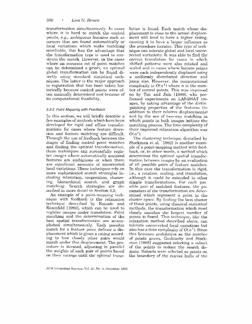
350 “ Lisa G. Brown
transformation simultaneously. In caseswhere it is hard to match the controlpoints, e.g., ambiguous features such ascorners that are found automatically orlocal variations which make matchingunreliable, this has the advantage thatthe transformation type is used to con-strain the match. However, in the caseswhere an accurate set of point matchescan be determined a priori, an optimalglobal transformation can be found di-rectly using standard statistical tech-niques. The latter is the major approachto registration that has been taken his-torically because control points were of-ten manually determined and because ofits computational feasibility.
3.3.2 Point Mapp/ng with Feedback
In this section, we will briefly describe afew examples of methods which have beendeveloped for rigid and affine transfor-mations for cases where feature detec-tion and feature matching are difficult.Through the use of feedback between thestages of finding control point matchesand finding the optimal transformation,these techniques can successfully regis-ter images where automatically acquiredfeatures are ambiguous or when thereare significant amounts of uncorrectedlocal variations. These techniques rely onmore sophisticated search strategies in-cluding relaxation, cooperation, cluster-ing, hierarchical search, and graphmatching. Search strategies are de-scribed in more detail in Section 4.3.
An example of a point-mapping tech-nique with feedback is the relaxationtechnique described by Ranade andRosenfeld [ 1980], which can be used toregister images under translation. Pointmatching and the determination of thebest spatial transformation are accom-plished simultaneously. Each possiblematch for a feature point defines a dis-placement which is given a rating accord-ing to how closely other pairs wouldmatch under this displacement. The pro-cedure is iterated, adjusting in parallelthe weights of each pair of points basedon their ratings until the optimal trans-
lation is found. Each match whose dis-placement is close to the actual displace-ment will tend to have a higher rating,causing it to have a larger influence asthe procedure iterates. This type of tech-nique can tolerate global and local uncor-rected variations. It was able to find thecorrect translation for cases in whichshifted patterns were also rotated andscaled and in cases where feature pointswere each independently displaced usinga uniformly distributed direction andjump size. However, the computationalcomplexity is 0( n4 ) where n is the num-ber of control points. This was improvedon by Ton and Jain [ 1989], who per-formed experiments on LANDSAT im-ages, by taking advantage of the distin-guishing properties of the features (inaddition to their relative displacements)and by the use of two-way matching inwhich points in both images initiate thematching process. The time complexity oftheir improved relaxation algorithm was0(n3).
The clustering technique described byStockman et al. [1982] is another exam-ple of a point-mapping method with feed-back, or, in other words, a method whichdetermines the optimal spatial transfor-mation between images by an evaluationof all possible pairs of feature matches.In this case the transformation is rigid,i.e., a rotation, scaling, and translation,although it could be extended to othersimple transformations. For each pos-sible pair of matched features, the pa-rameters of the transformation are deter-mined which represent a point in thecluster space. By finding the best clusterof these points, using classical statisticalmethods, the transformation which mostclosely matches the largest number ofpoints is found. This technique, like therelaxation method described above, cantolerate uncorrected local variations butalso has a time complexity of 0( n4 ). Sincethis becomes prohibitive as the numberof points grows, Goshtasby and Stock-man [ 1985] suggested selecting a subsetof the points to reduce the search do-main. Subsets were selected as points onthe boundary of the convex hulls of the
ACM Computmg Surveys, Vol 24, No 4. December 1992
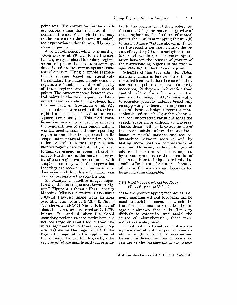
Image Registration Techniques w 351
point sets. (The convex hull is the small-est convex shape that includes all thepoints in the set.) Although the sets maynot be the same (if the images are noisy),the expectation is that there will be somecommon points.
Another refinement which was used by[Goshtasby et al. 86] was to use the cen-ter of gravity of closed-boundary regionsas control points that are iteratively up-dated based on the current optimal rigidtransformation. Using a simple segmen-tation scheme based on iterativelythresholding the image, closed-boundaryregions are found. The centers of gravityof these regions are used as controlpoints. The correspondence between con-trol points in the two images was deter-mined based on a clustering scheme likethe one used in [Stockman et al. 82].These matches were used to find the bestrigid transformation based on a leastsquares error analysis. This rigid trans-formation was in turn used to improvethe segmentation of each region until itwas the most similar to its correspondingregion in the other image (based on itsshape, independent of its position, orien-tation or scale.) In this way, the seg-mented regions become optimally similarto their corresponding region in the otherimage. Furthermore, the centers of grav-ity of each region can be computed withsubpixel accuracy with the expectationthat they are reasonably immune to ran-dom noise and that this information canbe used to improve the registration.
An example of satellite images regis-tered by this technique are shown in Fig-ure 7. Figure 7(a) shows a Heat CapacityMapping Mission Satellite Day-Visible
(HCMM Day-Vis) image from an areaover Michigan acquired 9/26/79. Figure7(b) shows an HCMM Night-IR image ofabout the same area acquired on 7/4/78.Figures 7(c) and (d) show the closedboundary regions (whose perimeters arenot too large or small) found from theinitial segmentation of these images. Fig-ure 7(e) shows the regions of (d), theNight-IR image, after the application ofthe refinement algorithm. Notice how theregions in (e) are significantly more simi-
lar to the regions of (c) than before re-finement. Using the centers of gravity ofthese regions as the final set of controlpoints, the results of mapping Figure 7(b)to match Figure 7(a) are shown in (f). Tosee the registration more clearly, the re-sult of negating (f) and overlaying it onto
(a) are shown in (g). The mean squareerror between the centers of gravity ofthe corresponding regions in the two im-ages was slightly less than one pixel.
Schemes of this type allow for globalmatching which is less sensitive to un-corrected local variations because (1) theyuse control points and local similaritymeasures, (2) they use information fromspatial relationships between controlpoints in the image, and (3) they are ableto consider possible matches based onlyon supporting evidence. The implementa-tion of these techniques requires moresophisticated search algorithms becausethe local uncorrected variations make thesearch space more difficult to traverse.Hence, these methods take advantage ofthe more subtle information availablebased on partial matches and the re-lationships between matches and bytesting more possible combinations ofmatches. However, without the use ofadditional constraints, such as imposedby camera geometry or the semantics ofthe scene, these techniques are limited tosmall affine transformations becauseotherwise the search space becomes toolarge and unmanageable.
3.3.3 Point Mapping without Feedback —
Global Polynomial Methods
Standard point-mapping techniques, i.e.,point mapping without feedback, can beused to register images for which thetransformation necessary to align the im-ages is unknown. Since it is often verydifficult to categorize and model thesource of misregistration, these tech-niques are widely used.
Global methods based on point match-ing use a set of matched points to gener-ate a single optimmal transformation.Given a sufficient number of points wecan derive the parameters of any trans-
ACM Computmg Surveys,Vol. 24, No. 4, December1992

352 . Lisa G. Brown
(b)
(c)
(e) (f-1
Figure 7. An example of satelhte images registered by a point-mapping technique with feedback, (a) and(b) are the original images; (c) and (d) show the closed-boundary regions found in the first Iteration; (e)shows the regions in (d) after they have been refined to make them as slmdar to the regions in (c) aspossible; (f) shows (b) transformed, based on these final regions to match (a); and (g) shows the finalregistration, i.e , (f) is overlaid onto (a). (Reprinted with permission from Goshtashy et al [ 1986], copyright1986, IEEE. )
formation either through approximation regression analysis or clustering. The ap-or interpolation. In approximation, pa- proximation approach assumes that therameters of the transformation are found matches are distorted by local noise. Thisso the matched points satisfy it as nearly noise cannot be removed by the transfor-ms possible. This is typically done with a mation, either because the transforma-statistical method such as least squares tion cannot account for it or because the
ACM Computmg Surveys, Vol 24, No. 4, December 1992
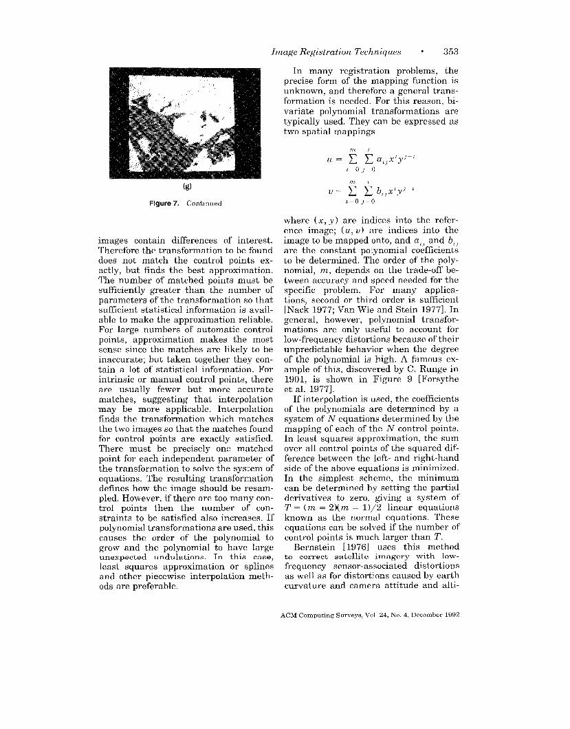
Image Registration Techniques w 353
(g)
figure 7. Continued
images contain differences of interest.Therefore the transformation to be founddoes not match the control points ex-actly, but finds the best approximation.The number of matched points must besufficiently greater than the number ofparameters of the transformation so thatsufficient statistical information is avail-able to make the approximation reliable.For large numbers of automatic controlpoints, approximation makes the mostsense since the matches are likely to beinaccurate; but taken together they con-tain a lot of statistical information. Forintrinsic or manual control points, thereare usually fewer but more accuratematches, suggesting that interpolationmay be more applicable. Interpolationfinds the transformation which matchesthe two images so that the matches foundfor control points are exactly satisfied.There must be precisely one matchedpoint for each independent parameter ofthe transformation to solve the system ofequations. The resulting transformationdefines how the image should be resam-pled. However, if there are too many con-trol points then the number of con-straints to be satisfied also increases. Ifpolynomial transformations are used, thiscauses the order of the polynomial togrow and the polynomial to have largeunexpected undulations. In this case,least squares approximation or splinesand other piecewise interpolation meth-ods are preferable.
In many registration problems, theprecise form of the mapping function isunknown, and therefore a general trans-formation is needed. For this reason, bi-variate polynomial transformations aretypically used. They can be expressed astwo spatial mappings
L= OJ=()
mz
L= OJ=O
where (x, y) are indices into the refer-ence image: (u. U) are indices into theu,,
image to be mapped onto, and a,J and bl,
are the constant polynomial coefficientsto be determined. The order of the ~olv-nomial, m, depends on the trade-off b~-tween accuracy and speed needed for thes~ecific ~roblem. ]lor manv a~~lica_
t~ons, sec~nd or third order ii su~~cient[Nack 1977; Van Wie and Stein 1977]. Ingeneral, however, polynomial transfor-mations are only useful to account forlow-frequency distortions because of theirunpredictable behavior when the degreeof the polynomial is high. A famous ex-ample of this, discovered by C. Runge in1901, is shown in Figure 9 [Forsytheet al. 1977].
If inter~olation is used. the coefficientsL
of the polynomials are determined by asystem of N equations determined by themapping of each of the N control points.In least squares approximation, the sumover all control ooints of the sauared dif-ference betwee~ the left- and ~ight-handside of the above equations is minimized.In the simplest scheme, the minimumcan be determined by setting the partialderivatives to zero, giving a system ofT = (m = 2)( m = 1)/2 linear equationsknown as the normal equations. Theseequations can be solved if the number ofcontrol points is much larger than T.
Bernstein [1976] uses this methodto correct satellite imagery with low-freauencv sensor-associated distortionsas ~ell a; for distortions caused by earthcurvature and camera attitude and alti-
ACM Computmg Surveys, Vol 24, No. 4, December 1992
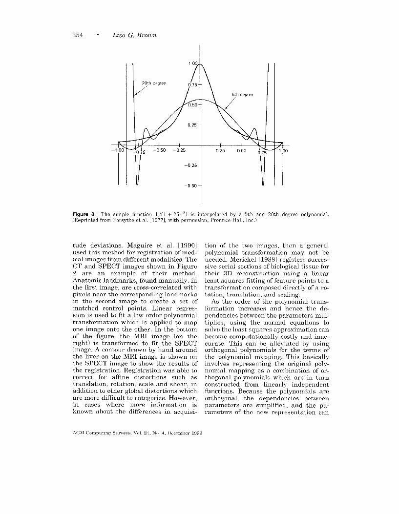
354 “ Lisa G. Brown
I
+!=–100
100
20th degree 0.75- -
/’
)75
/
–O 25- -
–o 50- - 1
IFigure 8. The simple function 1/(1 + 25x2) M interpolated by a 5th and 20th degree polynomial,(Reprinted from Forsythe et al. [1977], with permmsion, Prentice-Hall, Inc.)
tude deviations. Maguire et al. [1990]used this method for registration of med-ical images from different modalities. TheCT and SPECT images shown in Figure2 are an example of their method.Anatomic landmarks, found manually, inthe first image, are cross-correlated withpixels near the corresponding landmarksin the second image to create a set ofmatched control points. Linear regres-sion is used to fit a low order polynomialtransformation which is applied to mapone image onto the other. In the bottomof the figure, the MRI image (on theright) is transformed to fit the SPECTimage. A contour drawn by hand aroundthe liver on the MRI image is shown onthe SPECT image to show the results ofthe registration. Registration was able tocorrect for affine distortions such astranslation, rotation, scale and shear, inaddition to other global distortions whichare more difficult to categorize. However,in cases where more information isknown about the differences in acquisi-
tion of the two images, then a generalpolynomial transformation may not beneeded. Merickel [1988] registers succes-sive serial sections of biological tissue fortheir 3D reconstruction using a linearleast squares fitting of feature points to atransformation composed directly of a ro-tation, translation, and scaling.
As the order of the polynomial trans-formation increases and hence the de-pendencies between the parameters mul-tiplies, using the normal equations tosolve the least squares approximation canbecome computationally costly and inac-curate. This can be alleviated by usingorthogonal polynomials for the terms ofthe polynomial mapping. This basicallyinvolves representing the original poly-nomial mapping as a combination of or-thogonal polynomials which are in turnconstructed from linearly independentfunctions. Because the polynomials areorthogonal, the dependencies betweenparameters are simplified, and the pa-rameters of the new representation can
ACM Computmg Surveys, Vol 24, No 4, December 1992
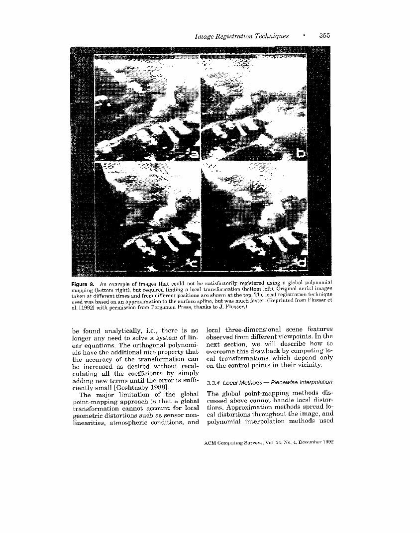
Image Registration Tech niques “ 355
Figure 9. An example of images that could not be satisfactorily registered using a global polynomialmapping (bottom right), but required finding a local transformation (bottom left). Original aerial imagestaken at different times and from different positions are shown at the top. The local registration techniqueused was based on an approximation to the surface spline, but was much faster. (Reprinted from Flusser etal. [ 1992] with permission from Pergamon Press, thanks to J. Flusser. )
be found analytically, i.e., there is nolonger any need to solve a system of lin-ear equations. The orthogonal polynomi-als have the additional nice property thatthe accuracy of the transformation canbe increased as desired without recal-culating all the coefficients by simplyadding new terms until the error is suffi-ciently small [Goshtasby 1988].
The major limitation of the globalpoint-mapping approach is that a globaltransformation cannot account for localgeometric distortions such as sensor non-linearities, atmospheric conditions, and
local three-dimensional scene featuresobserved from different viewpoints. In thenext section, we will describe how toovercome this drawback by computing lo-cal transformations which depend onlyon the control points in their vicinity.
3.3.4 Local Methods — Piecewise Interpolation
The global point-mapping methods dis-cussed above cannot handle local distor-tions. Approximation methods spread lo-cal distortions throughout the image, andpolynomial interpolation methods used
ACM Computmg Surveys,Vol 24, No. 4, December1992

356 ● Lisa G. Brown
with too many control points requirehigh-order polynomials which behave er-ratically. These methods are character-ized as global because a single transfor-mation is used to map one image ontothe other. This transformation is gener-ally found from a single computation us-ing all the control points equally.
In the local methods to be discussed inthis section, multiple computations areperformed, either for each local pieceor iteratively, spreading computationsto different neighborhoods. Only controlpoints sufficiently close, or perhaps,weighted by their proximity, influenceeach part of the mapping transformation.In other words, the mapping transforma-tion is no longer a single mapping withone set of parameters independent of po-sition. The parameters of the local map-ping transformation vary across the dif-ferent regions of the image, thus account-ing for distortions which differ across theimage. Local methods are more powerfuland can handle many distortions thatglobal methods cannot; examples includecomplex 3D scenes taken from differentviewpoints, deformable objects or mo-tions, and the effects of different sensorsor scene conditions. On the other hand,there is a trade-off between the power ofthese methods and their correspondingcomputational cost.
An example is shown in Figure 9 ofaerial images which could not be satis-factorily registered using polynomialmapping. In the top of the figure are twoimages taken at different times from dif-ferent positions of the aircraft. Using 17control points, a 2nd-order, polynomial,mapping function was fit using leastsquares approximation. The results ofusing this mapping are shown at the bot-tom right. Because of the local distor-tions, the average error is more than 5pixels. Using a local method proposed byFlusser [ 1992] the images were regis-tered (bottom left) with less than 1 pixelaccuracy.
The class of techniques which can beused to account for local distortion bypoint matching is piecewise interpola-tion. In this methodology, a spatial map-
Figure 10. The chest x-rays shown in Figure 1 areshown here after registration using surface sphnes.(Thanks to A Goshtasby.)
ping transformation for each coordinateis specified which interpolates betweenthe matched coordinate values. For Ncontrol points whose coordinates aremapped by
x, =F,(z[, y,)
Yj=Fv(xz, yt) i=l,.. .,lv
two bivariate functions (usually smooth)are constructed which take on these val-ues at the prescribed locations. Methodswhich can be applied in this instancemust be designed for irregularly spaceddata points since the control points areinevitably scattered. A study of surfaceapproximation techniques conducted byFranke [1979] compared these methodsexactly, testing each on several surfacesand evaluating their performance char-acteristics. As will be seen, the methodsused in Franke’s [ 1979] study, althoughnot designed for this purpose, underliemuch of the current work in local imageregistration.
Most of the methods evaluated byFranke [1979] use the general spline ap-proach to piecewise interpolation. Thisrequires the selection of a set of basisfunctions, B, ~, and a set of constraints tobe satisfied so that solving a system oflinear equations will specify the interpo-lating function. In particular, the splinesurface S( x, y ) can be defined as
S(x, y) = X~,,BL,, (X, Y)L,J
ACM Computing Surveys, Vol 24, No 4, December 1992

Image Registration Techniques ● 357
where V~ ~ are the control points. Formost sphnes, the basis functions are con-structed from low-order polynomials, andthe coefficients are computed using con-straints derived by satisfying end condi-tions and various orders of spatial conti-nuity. In the simplest case, a weightedsum of neighboring points is computedwhere the weights are related inverselywith distance such as in linear interpola-tion. These methods are called inverse-distance weighted interpolation. Anotheralternative is to have the set of neighbor-ing points determined from some parti-tioning of the image, such as triangula-tion. In this case, the weights depend onthe properties of the subregions. Thesemethods are called triangle-based meth-ods. Another set of methods consideredin Franke’s study are the global basisfunction type methods. These methodsare characterized by global basis func-tions G,,j( x, y) and coefficients Ah whichare determined by enforcing that theequation, S(X, y) = Z,,j A,,~G,,~(~, Y),
interpolates the data. These techniquesinclude the so called surface spline whichinterpolates the data by representing itas the surface of an infinite plate underthe imposition of point loads, i.e., thedata. Several variations of each methodwere examined, altering the basis func-tions, the weighting system, and the typeof image partitioning. This comprehen-sive study is a good reference for compar-ing the accuracy and complexity of sur-face interpolation techniques for scat-tered data.
Although all these methods computelocal interpolation values, they may ormay not use all points in the calculation.Those which do are generally more costlyand may not be suitable for large datasets. However, because global informa-tion can be important, many local meth-ods (i.e., methods which look for a localregistration transformation) employ pa-rameters computed from global informa-tion. The global basis function typemethods are an instance of this. The chestx-ray images shown in Figure 1 whichhave significant local distortions betweenthem, were registered by Goshtasby
[1988] using the surface spline variety ofthis technique. The results of this regis-tration are shown in Figure 10. Amongthe methods studied by Franke, most ofthe global basis function methods, in-cluding the surface spline, were amongthe most accurate, albeit they were alsoamong the slowest.
Flusser [1992] has modified this ap-proach to make it faster while maintain-ing satisfactory accuracy by adaptivelysubdividing the image, computing eachsubregion with a simpler, i.e., fastertransformation but only using this trans-formation if the errcr between it and theresults of using the surface spline aresufficiently small. (The error is computedby sampling and evaluating a subset ofrandom points in the region. ) If the erroris too large, the region is recursively sub-divided until the error criterion is met.The images in Figure 9 were registeredusing this technique. While global meth-ods are often the lmost accurate, localmethods which rely only on local compu-tations are not only more efficient butthey can also be locally controllable.These methods can be very useful formanual registration in a graphics envi-ronment. Regions of the image can beregistered without influencing other por-tions which have already been matched.Furthermore, in some cases, e.g., if localvariations of interest exist which shouldnot influence the transformation, thenlocal computations may actually bepreferable.
From the set of surface interpolationtechniques discussed in the study, manyregistration techniques are possible. Forinstance, Goshtasby [1986] proposed us-ing “optimal” triangulation of the controlpoints to partition the image into localregions for interpolation. Triangulationdecomposes the convex hull of the controlpoints of the image into triangular re-gions; in “optimal” triangulation, thepoints inside each triangular region arecloser to one of its vertices than to thevertices of any other triangle. The map-ping transformation is then computed foreach point in the image from interpola-tion of the vertices in the triangular patch
ACM Computmg Surveys, Vol 24, No. 4, December 1992
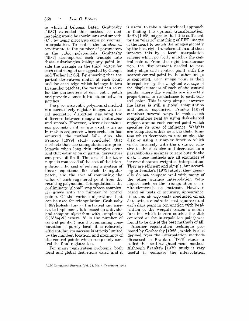
358 ● Lisa G. Brown
to which it belongs. Later, Goshtasby[1987] extended this method so thatmapping would be continuous and smooth(Cl ) by using piecewise cubic polynomialinterpolation. To match the number ofconstraints to the number of parametersin the cubic polyonmials, Goshtasby~1987] decomposed each triangle intothree subtriangles (using any point in-side the triangle as the third vertex foreach subtriangle) as suggested by Cloughand Tocher [1965]. By ensuring that thepartial derivatives match at each pointand for each edge which belongs to twotriangular patches, the method can solvefor the parameters of each cubic patchand provide a smooth transition betweenpatches.
The piecewise cubic polynomial methodcan successively register images with lo-cal geometric distortion assuming thedifference between images is continuousand smooth. However, where discontinu-ous geometric differences exist, such asin motion sequences where occlusion hasoccurred, the method fails. Also, theFranke [1979] study concluded thatmethods that use triangulation are prob-lematic when long thin triangles occurand that estimation of partial derivativescan prove difficult. The cost of this tech-nique is composed of the cost of the trian-gulation, the cost of solving a system oflinear equations for each triangularpatch, and the cost of computing thevalue of each registered point from theresulting polynomial. Triangulation is thepreliminary “global” step whose complex-ity grows with the number of controlpoints. Of the various algorithms thatcan be used for triangulation, Goshtasby[ 1987] selected one of the fastest and easi-est to implement. It is based on a divide-and-conquer algorithm with complexityO(N log N ) where N is the number ofcontrol points. Since the remaining com-putation is purely local, it is relativelyefficient, but its success is strictly limitedby the number, location, and proximity ofthe control points which completely con-trol the final registration.
For many registration problems, bothlocal and global distortions exist, and it
is useful to take a hierarchical approachin finding the optimal transformation.Ratib [1988] suggests that it is sufficientfor the “elastic” matching of PET imagesof the heart to match the images globallyby the best rigid transformation and thenimprove this by a local interpolationscheme which perfectly matches the con-trol points. From the rigid transforma-tion, the displacement needed to per-fectly align each control point with thenearest control point in the other imageis computed. Each image point is theninterpolated by the weighted average ofthe displacements of each of the controlpoints, where the weights are inverselyproportional to its distance to each con-trol point. This is very simple; howeverthe latter is still a global computationand hence expensive. Franke [19791mentions several ways to make suchcomputations local by using disk-shapedregions around each control point whichspecifies its area of influence. Weightsare computed either as a parabolic func-tion which decreases to zero outside thedisk or using a simpler function whichvaries inversely with the distance rela-tive to the disk size and decreases in aparabolic-like manner to zero outside thedisk. These methods are all examples ofinverse-distance weighted interpolation.They are efficient and simple, but accord-ing to Franke’s [1979] study, they gener-ally do not compare well with many ofthe other surface interpolation tech-niques such as the triangulation or fi-nite-element-based methods. However,based on tests of accuracy, appearance,time, and storage costs conducted on sixdata sets, a quadratic least squares fit ateach data point in conjunction with local-ization of the weights (using a simplefunction which is zero outside the diskcentered at the interpolation point) wasfound to be one of the best methods of all.
Another registration technique pro-posed by Goshtasby [1988], which is alsoderived from the interpolation methodsdiscussed in Franke’s [1979] study iscalled the local weighted-mean method.Although Franke’s [1979] study is veryuseful to compare the interpolation
ACM Comput]ng Surveys, Vol 24, No 4, December 1992

Image Registration Techniques “ 359
methods, the application of these tech-niques to real registration problems ex-poses other types of limitations and de-pendencies. In the local weighted-meanmethod, a polynomial of order n is foundfor each control point which fits its n – 1
nearest control points. A point in theregistered image is then computed as theweighted mean of all these polynomialswhere the weights are chosen to corre-spond to the distance to each of theneighboring control points and to guar-antee smoothness everywhere. The com-putational complexity of the localweighted method depends linearly on theproduct of the number of controls points,P, the square of the order of the polyno-mial, ill 2, and the size of the image, lV2,i.e., it complexity is 0( Pilf2~2). Again,the method relies on an entirely localcomputation, each polynomial is basedon local information, and each point iscomputed using only local polynomials.Thus, the efficiency is good comparedwith methods whose parameters rely onglobal computations, but the procedure’ssuccess is limited by the accuracy andselection of the control points. In fact,during implementation, only a subset ofthe known control points was used sothat each polynomial’s influence wouldbe spread far enough to cover image loca-tions without points.
Notice that in comparison to the globalpoint-mapping methods of the previoussection, the complexity of local interpola-tion methods is vastly slower. Becausethe parameters of the transformation de-pend on the location in the image, a sep-arate calculation, which may or may notbe global, is effectively performed, foreach subregion, to determine its parame-ters. Alternatively, when the mappingtransformation is computed, a more com-plicated calculation must be performedfor each pixel which depends on its rela-tive location with respect to the parti-tioning or the other control points. Thisis the price we pay if we want to registerimages with local distortions.
Also, although these methods only usea local computation for each mapping, wehave presumed that the control points
have already been found and matched.This is a critical part of the registrationand its final computational complexity.
Furthermore, the implementation ofthese methods is often complicated bymissing control poinlts and insufficientinformation concerning how to findmatches. Yet, the accuracy of thesemethods is highly dependent on the num-ber, positions, and accuracy of thematches. Although they are sometimescapable of correcting local distortions, lo-cal point-mapping methods do so in asingle pass; there is no feedback betweenthe point matching and the interpola-tion or approximation. Nor do they takeadvantage of several algorithmic tech-niques which can imlprove and speed upthe extraction of local distortions.Namely, these are iteration, a hierarchi-cal approach, and cooperation. This isbecause these techniques (by definition)are based on control points which havebeen found and matched prior to the de-termination of the registration transfor-mation. There is no relationship inherentin the structure of these techniques whichrelates the control point matches and theoptimal transformation. In the next sec-tion, another class of methods is de-scribed which overcome this dependenceon the accurate matching of control pointsby exploiting these algorithmic tech-niques and by the use of an elastic modelto constrain the regis ixation process.
3.4 Elastic Model-Baseld Matching
The most recent work in image registra-tion has been the development of tech-niques which exploit elastic models. In-stead of directly applying piecewiseinterpolation to compute a transforma-tion to map the COIItrOl points of oneimage onto another, these methods modelthe distortion in the Image as the defor-mation of an elastic material. In otherwords, the registration n transformation isthe result of the deformation of an elasticmaterial with the minimal amount ofbending and stretching. The amount ofbending and stretching is characterizedby the energy state c}f the elastic mate-
ACM Computmg Surveys, Vol. 24, No, 4, December 1992
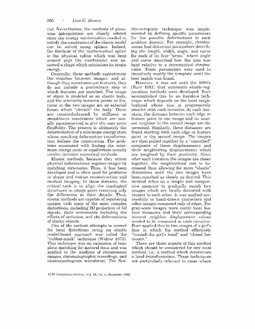
360 “ Lisa G. Brown
rial. Nevertheless, the methods of piece-wise interpolation are closely relatedsince the energy minimization needed tosatisfy the constraints of the elastic modelcan be solved using splines. Indeed,the forebear of the mathematical splineis the physical spline which was bentaround pegs (its constraints) and as-sumed a shape which minimizes its strainenergy.
Generally, these methods approximatethe matches between images, and al-though they sometimes use features, theydo not include a preliminary step inwhich features are matched. The imageor object is modeled as an elastic body,and the similarity between points or fea-tures in the two images act as externalforces which “stretc& the body. Theseare counterbalanced by stiffness orsmoothness constraints which are usu-ally parameterized to give the user someflexibility. The process is ultimately thedetermination of a minimum-energy statewhose resulting deformation transforma-tion defines the registration. The prob-lems associated with finding the mini-mum-energy state or equilibrium usuallyinvolve iterative numerical methods.
Elastic methods, because they mimicphysical deformations, register images bymatching structures. Thus, it has beendeveloped and is often used for problemsin shape and motion reconstruction andmedical imaging. In these domains, thecritical task is to align the topologicalstructures in image pairs removing onlythe differences in their details. Thus,elastic methods are capable of registeringimages with some of the most complexdistortions, including 2D projection of 3Dobjects, their movements including theeffects of occlusion, and the deformationsof elastic objects.
One of the earliest attempts to correctfor local distortions using an elasticmodel-based approach was called the“rubber-mask technique [Widros 1973].This technique was an extension of tem-plate matching for natural data and was
applied to the analysis of chromosomeimages, chromato~aphic recordings, andelectrocardiogram waveforms. The flex-
ible-template technique was imple-mented by defining specific parametersfor the possible deformations in eachproblem domain. For example, chromo-somes had distortion parameters describ-ing the length, width, angle, and curvefor each of its four “arms,” where angleand curve described how the arm wasbent relative to a stereotypical chromo-some. These parameters were used toiteratively modify the template until thebest match was found.
However, it was not until the 1980’s[Burr 1981] that automatic elastic-reg-istration methods were developed. Burraccomplished this by an iterative tech-nique which depends on the local neigh-borhood whose size is progressivelysmaller with each iteration. At each iter-ation, the distance between each edge orfeature point in one image and its near-est neighbor in the second image are de-termined. Similarly, these distances arefound starting with each edge or featurepoint in the second image. The imagesare then pulled together by a “smoothed”composite of these displacements andtheir neighboring displacements whichare weighted by their proximity. Sinceafter each iteration the images are closertogether, the neighborhood size is de-creased thus allowing for more “elastic”distortions until the two images havebeen matched as closely as desired. Thismethod relies on a simple and inexpen-sive measure to gradually match twoimages which are locally distorted withrespect to each other. It was applied suc-cessfully to hand-drawn characters andother images composed only of edges. Forgray-scale images more costly local fea-ture measures and their correspondingnearest neighbor displacement valuesneeded to be computed at each iteration.Burr applied this to two images of a girl’sface in which his method effectively“turned the girl’s head” and “closed hermouth.”
There are three aspects of this methodwhich should be considered for any localmethod, i.e., a method which determinesa local transformation. These techniquesare particularly relevant in cases where
ACM Comput]ng Surveys, Vol 24, No. 4, December 1992
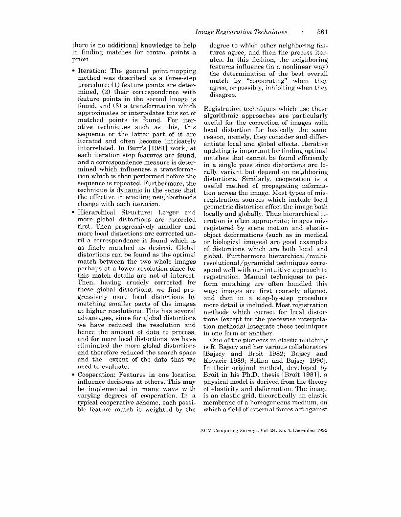
Image Registration Techniques ● 361
there is no additional knowledge to helpin finding matches for control points apriori.
●
●
0
Iteration: The general point-mappingmethod was described as a three-stepprocedure: (1) feature points are deter-mined, (2) their correspondence withfeature points in the second image isfound, and (3) a transformation whichapproximates or interpolates this set ofmatched points is found. For iter-ative techniques such as this, thissequence or the latter part of it areiterated and often become intricatelyinterrelated. In Burr’s [1981] work, ateach iteration step features are found,and a correspondence measure is deter-mined which influences a transforma-tion which is then performed before thesequence is repeated. Furthermore, thetechnique is dynamic in the sense thatthe effective interacting neighborhoodschange with each iteration.
Hierarchical Structure: Larger andmore global distortions are correctedfirst. Then progressively smaller andmore local distortions are corrected un-til a correspondence is found which isas finely matched as desired. Globaldistortions can be found as the optimalmatch between the two whole imagesperhaps at a lower resolution since forthis match details are not of interest.Then, having crudely corrected forthese global distortions, we find pro-gressively more local distortions bymatching smaller parts of the imagesat higher resolutions. This has severaladvantages, since for global distortionswe have reduced the resolution andhence the amount of data to process,and for more local distortions, we haveeliminated the more global distortionsand therefore reduced the search spaceand the extent of the data that weneed to evaluate.
Cooperation: Features in one locationinfluence decisions at others. This may
be implemented in many ways withvarying degrees of cooperation. In atypical cooperative scheme, each possi-ble feature match is weighted by the
degree to which other neighboring fea-tures agree, and then the process iter-ates. In this fashion, the neighboringfeatures influence (in a nonlinear way)the determination of the best overallmatch by “cooperating” when theyagree, or possibly, inhibiting when theydisagree.
Registration techniques which use thesealgorithmic approaches are particularlyuseful for the correction of images withlocal distortion for basically the samereason, namely, they consider and differ-entiate local and global effects. Iterativeupdating is important for finding optimalmatches that cannot be found efficientlyin a single pass since distortions are lo-cally variant but depend on neighboringdistortions. Similarly, cooperation is auseful method of propagating informa-tion across the image. Most types of mis-registration sources which include localgeometric distortion effect the image bothlocally and globally. Thus hierarchical it-eration is often appropriate; images mis-registered by scene motion and elastic-object deformations (such as in medicalor biological images]} are good examplesof distortions which are both local andglobal. Furthermore hierarchical/multi-resolutional/pyramidal techniques corre-spond well with our intuitive approach toregistration. Manual techniques to per-form matching are often handled thisway; images are first coarsely aligned,and then in a stelp-by-step proceduremore detail is included. Most registrationmethods which correct for local distor-tions (except for the piecewise interpola-tion methods) integri~te these techniquesin one form or another.
One of the pioneers in elastic matchingis R. Bajscy and her various collaborators[Bajscy and Broit 1982; Bajscy andKovacic 1989; Solina and Bajscy 1990].In their original method, developed byBroit in his Ph.D. thesis [Broit 1981], aphysical model is derived from the theoryof elasticity and deformation. The imageis an elastic grid, theoretically an elasticmembrane of a homogeneous medium, onwhich a field of external forces act against
ACM Computmg Surveys, Vol 24, No. 4. December 1992

362 - Lisa G. Brown
a field of internal forces. The externalforces cause the image to locally deformtowards its most similar match while theinternal forces depend on the elasticitymodel. From an energy minimizationstandpoint, this amounts to:
cost = deformation energy
— similarity energy.
To find the minimum energy, a set ofpartial differential equations are derivedwhose solution is the set of displace-ments which register the two images. Forexample, to register a CT image of ahuman brain (the reference image) witha corresponding image from an atlas, aregular grid is placed over the referenceimage which can be thought of as theelastic mesh. This mesh is deformed ac-cording to the external forces, derivedfrom the differences between the con-tours of the brains in the two images andthe internal forces which arise from theproperties of the elastic model. The de-formation of this grid (and the necessaryinterpolation) gives a mapping betweenthe reference image and the atlas. Bajcsyand Broit [1982] applied this techniqueto 2D and 3D medical images and claimgreater efficiency over Burr’s [1981]method. As in Burr’s [ 1981] methoditeration and cooperation are clearlyutilized.
In more recent work with Bajscy andKovacic [ 1989] CT scans of the humanbrain are elastically matched with a 3Datlas. As with many local techniques, itis necessary first to align images globallyusing a rigid transformation before ap-plying elastic matching. In this way it ispossible to limit the differences in theimages to small, i.e., local, changes. Theirwork follows the earlier scheme proposed
by Broit [1981], but this is extended in ahierarchical fashion. The same set of par-tial differential equations describing theelastic model serve as the constraintequations. The external forces, which ul-timately determine the final registration,are computed as the gradient vector of alocal similarity function. These forces acton the elastic grid by locally pulling it
towards the maximum of the local simi-larity function. In particular, for eachsmall region in one image, we measurethe correlation with this region withnearby regions in the second image. Thechange in these measures is used as theexternal forces in the equations of theelastic model. This requires that the lo-cal-similarity function have a maximumthat contributes unambiguous informa-tion for matching. Therefore, only forcesin regions where there is a substantialmaximum are used. The system of equa-tions of the elastic model is then solvednumerically by finite-difference approxi-mation for each level, starting at thecoarsest resolution. The solution at thecoarsest level is interpolated and used asthe first approximation to the next finerlevel.
The hierarchical approach has severaladvantages. If the elastic constants inthe equation are small, the solution iscontrolled largely by the external forces.This causes the image to warp unrealisti-cally and for the effects of noise to beamplified. By deforming the image step-by-step, larger elastic constants can beused, thereby producing a series ofsmooth deformations which guide the fi-nal transformation. The multiresolutionapproach also allows the neighborhoodsfor the similarity function to always besmall and hence cheap yet also to coverboth global and local deformations of var-ious sizes. In general, the coarse-to-finestrategy improves convergence since thesearch for local-similarity function max-ima is guided by results at coarser levels.Thus, like Burr’s [1981] method, itera-tion, cooperation, and a hierarchicalstructure are exploited.
Recently, techniques similar to elasticmatching have been used to recover shapeand nonrigid body motion in computervision and to make animation in com-puter graphics. The major difference inthese techniques to the methods dis-cussed so far is that the elastic model isapplied to an object as opposed tothe image grid. Hence, some sort of seg-mentation, i.e., a grouping of adjacentpixels in the image into meaningful units,
ACM Computmg Surveys, Vol. 24, No. 4, December 1992

Image Registration Techniques 9 363
namely, real-world objects, must precedethe analysis. The outcome is no longer adeformation to register images butparameters to match images to objectmodels. One example can be found inTerzopoulos et al. [1987]. They proposeda system of energy constraints for elasticdeformation for shape and motion. recov-ery which was applied to a temporal se-quence of stereo images of a moving fin-ger. The external forces of the de-formable model are similar to those usedin elastic registration; they constrain thematch based on the image data. Ter-zopoulos et al. [1987] use the deprojec-tion of the gradient of occluding contoursfor this purpose. However, the internalforces are no longer varied with simpleelastic constants but involve a more com-plicated model of expected object shapeand motion. In their case, the internalforces induce a preference for surfacecontinuity and axial symmetry (a sort of“loose” generalized cylinder using a rub-ber sheet wrapped around an elasticspine). This type of reconstruction hasthe advantage of being capable of inte-grating information in a straightforwardmanner. For example, although occlud-ing boundaries in stereo image pairs cor-respond to different boundary curves ofsmooth objects, they can appropriately berepresented by distinct external forces.Higher-level knowledge can similarly beincorporated. Although these techniquesare not necessary for the ordinary regis-tration of 2D images, performing intelli-gent segmentation of images before reg-istration is potentially the most accurateway to match images and to expose thedesired differences between them.
3.5 Summary
In Section 3, most of the basic registra-tion techniques currently used have beendiscussed. Methods are characterized bythe complexity of their correspondingtransformation class. The transformationclass can be determined by the source ofmisregistration. Methods are then lim-ited by their applicability to this trans-formation class and the types of uncor-
rected variations they can tolerate. Theearly approaches using cross-correlationand other statistical measures of point-wise similarity are only applicable forsmall well-defined affine transfor-mations. Fourier methods are similarlylimited but can be more effective in thepresence of frequency-dependent noise. Iflocal uncorrected variations are presentthen the search for the afline transfor-mation must be more sophisticated. Inthis case point mapping with feedback isrecommended so tlhat search space ismore thoroughly investigated.
If the type of transformation is un-known but the misalignment between theimages varies smoothly, i.e., the mis-alignment is more complex than aflinebut is still global, then point mappingwith feedback can lbe used. If it is pos-sible to find accurate matches for controlpoints then point mapping by interpola-tion is sufficient. For cases with localuncorrected variation and many inaccu-rate control point matches then approxi-mation is necessary.
If global transformations are not suffi-cient to account for t’he misalignment be-tween the images, then local methodsmust be used. In this case, if it is possibleto perform accurate feature matching,then piecewise interpolation methods canbe successively applied. However, if un-corrected local variations are present,then it is often necessary to use addi-tional knowledge tc~ model the trans-formation such as an elastic mem-brane for modeling the possible imagedeformations.
4. CHARACTERISTICSI OF
REGISTRATION METHODS
The task of determining the best spatialtransformation for thle registration of im-ages can be broken {down into major com-ponents:
● feature space
_ similarity metric
- search space
0 and search strategy.
Every registration technique can be
ACM Computing Surveys, Vol 24, No. 4, December 1992

364 ● Lisa G. Brown
thought of as a selection for each of thesefour components. As described earlier, thebest available knowledge of the source ofmisregistration determines the transfor-mation needed, i.e., the search space.This, in turn, determines the complexityand kind of method. Knowledge of othervariations (which are not corrected for bythe transformation) can then be used to
decide on the best choices for the otherthree major components listed above. Ta-bles 6, 7, and 8 give several examples ofeach of these components. In addition,these tables briefly describe the at-tributes for each technique and give ref-erences to works which discuss their usein more detail. In the following section,each of the components of registration isdescribed more fully.
4.1 Feature Space
The first step in registering two imagesis to decide on the feature space to use
for matching. This may be the raw pixelvalues, i.e., the intensities, but othercommon feature spaces include: edges,contours, surfaces; salient features suchas corners, line intersections, and pointsof high curvature; statistical featuressuch as moment invariants or centroids;and higher-level structural and syntacticdescriptions. Salient features refer tospecific pixels in the image which containinformation indicating the presence of aneasily distinguished meaningful charac-teristic in the scene. Statistical features
refer to measures over a region (the re-gion may be the outcome from a prepro-cessing segmentation step), which repre-sent the evaluation of the region. Thefeature space is a fundamental aspect ofimage registration just as it is for almostall other high-level image processing orcomputer vision tasks. For image regis-tration it influences
● which properties of the sensor andscene the data are sensitive to (often,features are chosen to reduce sensornoise or other distortions, such as illu-mination and atmospheric conditions,i.e., Type II variations),
o which properties of the images will be
matched (e.g., more interested inmatching structures than texturalproperties, i.e., ignore Type III varia-tions),
s the computational cost by either reduc-ing the cost of similarity measures or,on the other hand, increasing the pre-computations necessary.
The point is, by choosing the best featurespace it is possible to significantly im-prove registration. Features can be foundon each image independently in a prepro-cessing step, and this in turn reduces theamount of data to be matched. It is oftenpossible to choose a feature space whichwill eliminate uncorrected variationswhich might otherwise make matchingunreliable. If there are variations of in-terests, the feature space can be limitedto the types of structures for which thesevariations are not present. Similarly, fea-tures can highlight those parts of theimage which represent scene elementswhich have undergone the expected mis-alignment. This is usually done by pre-processing the images in an attempt toextract intrinsic structure. By this wemean finding the pixels in the imageswhich accurately represent significantphysical locations in the world as op-posed to lighting changes, shadows, orchanges in reflectivity.
Extracting intrinsic structure reducesthe effects of scene and sensor noise,forces matching to optimize structuralsimilarity, and reduces the correspond-ing data to be matched. Image enhance-ment techniques which process an imageto make it more suitable for a specificapplication [Gonzalez and Wintz 1977]can be used to emphasize structural in-formation. Typical enhancement tech-niques include contrast enhancement,which increases the range of intensityvalues, image smoothing, which removeshigh-frequency noise, and image sharp-ening, which highlights edges. An exam-ple of an enhancement technique whichis particularly suitable for registration ishomomorphic filtering. This can be usedto control the effects of illumination andenhance the effects of reflectance.
ACM Computmg Surveys, Vol. 24, No 4. December 1992

Image Registration Tech niques w 365
Table 6. Feature Spaces Used m Image Reglstrat!on—
Feature Spaces and Them Attributes
RAW INTENSI~—most information
—
EDGES—intrinsic structure, less sensitive to noise—
Edges [Nack 1977]Contours [Medioni and Nevatia 1984]Surfaces [Pelizzari et al. 1989]
SALIENT FEATURES—intrinsic structure. accurate positioning—
Points of locally maximum curvature on contour lines [Kanal et al. 19811Centers of windows having locally maximum variances [Moravec 198 1]Centers of gravity of closed-boundary regions [Goshtasby 1986]Line intersections [Stockman et al. 1982]Fourier deschptors [Kuhl and Giardina 1982]
STATISTICAL FEATURES—use of all information, good for rigid transformations, assumptions—
concerning spatial scatteringMoment invariants [Goshtasby 1985]
Centroid/principal axes [Rosenfeld and Kak 1982]
HIGHER-LEVEL FEATURES—use relations and other higher-level information, good for inexact andlocal matching
Structural features: graphs of subpattern configurations [Mohr et al. 1990]Syntactic features: grammars composed from patterns [Bunke and Sanfehu 1’990]Semantic networks: scene regions and their relations [Faugeras and Price 19811
MATCHING AGAINST MODELS—accurate intrinsic structure, noise in one image only—
Anatomic atlas [Dann et al. 1989]Geographic map [Maitre and Wu 1987]Object model [Terzopoulos et al. 1987]
Table 7. Similarity Metrics Used m Image Registration—
Slmdaru+y Metric Aduuntages
Norrnahzed cross-correlation function
—
accurate for white noise but not tolerant of[Rosenfeld and Kak 1982] local distortions, sharp peak in correlation
space difficult to find
Correlation coefficient [Svedlow et al. 1976] similar to above but has absolute measure
Statistical correlation and matched filtem
—
[Pratt 1978]
if noise can be modeletd
Phase-correlation [De Castro and Morandi 1987]
—tolerant of frequency-dependent noise
Sum of absolute differences of intensity
—
efficient computation, good for finding
[Barnea and Silverman 1972] matches with no local distortions
Sum of absolute differences of contours can be efficiently computed using “chamfer”
[Barrow et al. 1977] matching, more robust against local
distortions-not as sharply peaked
Contour/surface differences [Pelizzari et al. 1989]
—
for structural registration
Number of sign changes in pointwise intensity good for dissimilar images
difference [Venot et al. 1989]
Higher-level metrics: structural matching
—optimizes match basecl on features or relations
tree and graph distances [Mohr et al. 1990], syn- of interest
tactic matching automata [Bunk. and Sanfeliu 1990]
ACM Computmg Surveys, VO1 24, No. 4, December 1992

366 ● Lisa G. Brown
Table 8. Search Strategies Used In Image Reglstratlon
Search Strategy Advantages and Reference Examples
Decision Sequencing Improved efllciency for similarity optimization for rigid
transformations [Barnea and Silverman 1972]
Relaxation Practical approach to find global transformations when
local distortions are present, exploits spatial relatlons
between features [Hummel and Zucker 1983; Pmce 1985:
Ranade and Rosenfeld 1980; Shapmo and Harahck 1990]
Dynamic Programmmg Good efficiency for finding local transformations when anintrinsic ordering for matchmg is present [ Guilloux 1986;Maitre and Wu 1987; Milios 1989; Ohta et al. 1987]
Generalized Hough Transform For shape matching of rigidly displaced contours by map-ping edge space into “dual-parameter” space [Ballard 1981;Davis 1982]
Linear Programming For solving system of linear mequahty constraints, usedfor finding n~d transformation for point matching withpolygon-shaped error bounds at each point [Bau-d 1984]
Hierarchical Techniques Apphcable to improve and speed up many different
approaches by guiding search through progressively finerresolutions [ BaJ scy and Kovacic 1989; Bieszk and Fram 1987;Davis 1982; Paar and Kropatsch 1990]
Tree and Graph Matching Uses tree/graph properties to minimize search, goodfor inexact and matching of higher-level structures[Gmur and Bunke 1990: Sanfeliu 1990]
Edges, contours, and boundaries, be-cause they represent much of the intrin-sic structures of an image, are frequentlyused as a feature space. Using the posi-tion of edges in registration has the ad-vantages of being fast and invariant tomany types of uncorrected variations.However, edge points are not typicallydistinguishable and therefore are notgood candidates for point matching. Ingeneral using edges requires a region-based similarity measure.
Salient features are chosen to be in-variant to uncorrected variations and tobe highly distinguishable. Dominantpoints along curves are frequently usedsuch as corners, intersections, inflectionpoints, points of high curvature, andpoints along discontinuities [Katuri1991]. Higher-level shape descriptors,such as topological, morphological, andFourier descriptors are also used in orderto be more unique and discriminating[Pavlidis 1978]. In the absence of shapeor curves interesting points in regionsare found. The most widely used meas-ure of this sort is the Moravec interest
operator which finds points of greatestlocal variance [Moravec 1981].
Statistical measures describe charac-teristics of regions which may or may notspecify a location in the image. One pos-sibility is to assume objects are ellipsoid-like scatters of particles uniformly dis-tributed in space. In this case, thecenters of mass and the correspondingprincipal axes (computed fl-om their co-variance matrices) can be used to glob-ally register them. Another popularchoice is to use moment invariants al-though they are computationally costly(lower-order moments are sometimesused first to guide the match and speedthe process [Goshtasby 1985; Mahs andRezaie 1987]) and can only be used tomatch images which have been rigidlytransformed. They are one member of theclass of features used because their val-ues are independent of the coordinatesystem. However, as scalars they have nospatial meaning. Matching is accom-plished by maximizing the similarity be-tween the values of the moments in thetwo images. Mitchie and Aggarwal [ 1983]
ACM Computing Surveys, Vol. 24, No 4, December 1992

Image Registration Techniques s 367
suggest the use of shape-specific points,
such as the centroid and the radius-weighted mean, for preregistration tosimplify shape matching. These featuresare more easily computed, are similarlynoise tolerant, but more importantl-y, they are spatially meaningful. Theycan be used as control points in point-mapping registration methods ratherthan in similarity optimization.
When sufficient information or data areavailable, it is useful to apply registra-tion to an atlas, map, graph, or modelinstead of between two data images. Inthis way distortion is present in only oneimage, and the intrinsic structures of in-terest are accurately extracted.
The feature space is the representationof the data that will be used for registra-tion. The choice of feature space deter-mines what is matched. The similaritymetric determines how matches arerated. Together the feature space andsimilarity metric can ignore many typesof variations which are not relevant tothe proper registration (Types II and III)and optimize matching for features whichare important. But, while the featurespace is precomputed on each image be-fore matching, the similarity metric iscomputed using both images and for eachtest.
4.2 Similarity Measure
The second step made in designing orchoosing a registration method is the se-lection of a similarity measure. This stepis closely related with the selection of thematching feature since it measures thesimilarity between these features. Theintrinsic structure, i.e., the invarianceproperties of the image, are extracted byboth the feature space, and through thesimilarity measure. Typical similaritymeasures are cross-correlation with orwithout prefiltering (e.g., matched filtersor statistical correlation), sum of abso-lute differences (for better efficiency), andFourier invariance properties such asphase correlation. Using curves and sur-faces as a feature space requires meas-ures such as sum of squares of differ-
ences between nearest points. Structuralor syntactic methods have measureshighly dependent on their properties. Forexample, the minimum change of en-tropy between “random” graphs is usedas a similarity criteria by Wong and You[1985] for noisy data in structural pat-tern recognition.
The choice of similku-ity metric is one ofthe most important elements of how theregistration transformation is deter-mined. Given the search space of possibletransformations, the similarity metricmay be used to find the parameters ofthe final registration transformation. Forcross-correlation or tlhe sum of the abso-lute differences the transformation isfound at the peak wdue. Similarly, thepeak value determines the best controlpoint match for point-mapping methods.Then the set of control point matches isused to find the appropriate transforma-tion. However, in elastic-model-basedmethods, the transformation is found forwhich the highest similarity is balancedwith an acceptable level of elastic stress.
Similarity measures, like featurespaces, determine what is being matchedand what is not. First the feature spaceextracts the informatl~on from each imagewhich will be used for matching. Thenthe similarity measure evaluates this in-formation from both images. The criteriaused by the similarity measure deter-mines what types of matches are opti-mal. The ability of a registration methodto ignore uncorrected variations ulti-mately depends on both the feature spaceand the similarity measure. If gray val-ues are used, instead of features, a simi-larity measure might be selected to bemore noise tolerant since this was notdone during feature detection. Correla-tion and its sequential counterpart areoptimized for exact matches therefore re-quiring image preprocessing if too muchnoise is present. Edge correlation, i.e.,correlation of edge images, is a standardapproach. Fourier methods, such asphase correlation, can be used on raw
images when there ILS frequency-depen-dent noise. Another possible similaritymeasure, suggested bjy Venot et al. [ 1984],
ACM Computmg Surveys, Vol 24, No 4, December 1992

368 . Lisa G. Brown
is based on the number of sign changesin the pointwise subtraction of the twoimages. If the images are aligned andnoise is present, the number of signchanges is high, assuming any point isequally likely to be above zero as it is tobe below. This is most advantageous incomparison to classical techniques whenthe images are dissimilar. Differences inthe images affect the classical measuresaccording to the gray values in the loca-tions which differ whereas the number ofsign changes decreases only by the spa-tial size of these differences.
The feature space and similarity met-ric, as discussed, can be selected to re-duce the effects of noise on registration.However, if the noise is extracted in thefeature space this is performed in a sin-gle step precomputed independently oneach image prior to matching. Specialcare must be taken so that image fea-tures represent the same structures inboth images when, for example, imagesare acquired from different sensors. Onthe other hand, the proper selection of afeature space can greatly reduce thesearch space for subsequent calculations.Because similarity measurements useboth images and are computed for eachtransformation, it is possible to choosesimilarity measures which increase thedesirability of matches even though dis-tortions exist between the two correctlyregistered images. The method based onthe number of sign differences describedabove is an example. Similarity metricshave the advantage that both images areused and that its measurements are rela-tive to the measurements at other trans-formations. Of course, this is paid for byan increase in computational cost since itmust be repeated for each test.
Lastly, using features reduces the ef-fects of photometric noise but has littleeffect on spatial distortions. Similaritymeasures can reduce both types of distor-tions such as with the use of region-basedcorrelation and other local metrics. It isimportant to realize, however, that thespatial distortions purposely not recog-nized by similarity metrics must only bethose that are not part of the neededtransformation. For example, when simi-
larity metrics are chosen for finding theelastic transformation of images in whichcertain differences between images are ofinterest (such as those in the examples inthe second class of problems of Table 2)they should find similarity in structurebut not in more random local differences.
4.3 Search Space and Strategy
Because of the large computational costsassociated with many of the matchingfeatures and similarity measures, the laststep in the design of a registrationmethod is to select the best search strat-egy. Remember, the search space is gen-erally the class of transformations fromwhich we would like to find the optimaltransformation to align the images. Wecan evaluate each transformation candi-date using the similarity measure on thepreselected features. However, in manycases, such as with the use of correlationas the similarity measure, it is importantto reduce the number of measures to becomputed. The greater the complexity ofthe misalignment between images themore severe this requirement is. For in-stance, if the only misalignment is trans-lation, a single template correlated at allpossible shifts is sufficient. For moregeneral affine transformations, manytemplates or a larger search area mustbe used for classical correlation methods.The problem gets even worse if local geo-metric distortions are present. Finally, ifuncorrected variations have not beeneliminated by the feature space and simi-larity metric, then the search for the op-timum is also made more difficult, sincethere are more likely to be several localoptima and a less monotonic space.
In most cases, the search space is thespace of all possible transformations.Examples of common search strategiesinclude hierarchical or multiresolutiontechniques, decision sequencing, relax-ation, generalized Hough transforms, lin-ear programming, tree and graph match-ing, dynamic programming, and heuristicsearch.
Search Space. The model of thetransformation class underlying eachregistration technique determines the
ACM Computmg Surveys, Vol 24, No 4. December 1992
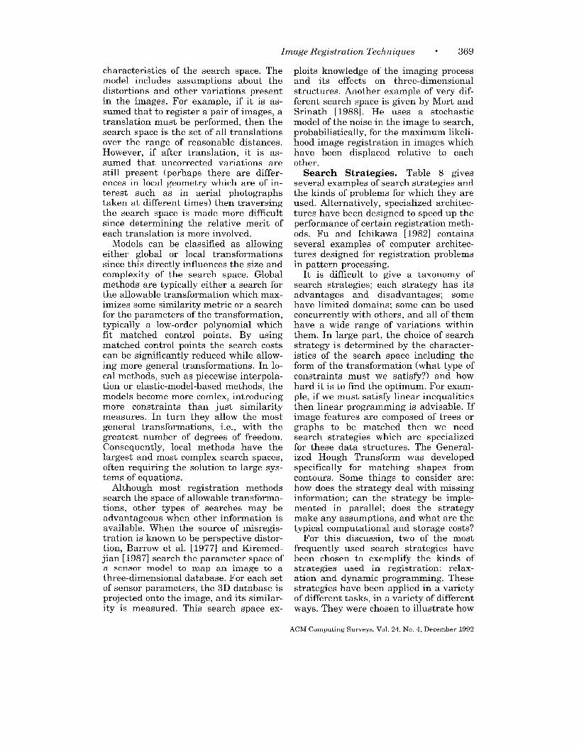
Image Registration Techniques ● 369
characteristics of the search space. Themodel includes assumptions about thedistortions and other variations presentin the images. For example, if it is as-sumed that to register a pair of images, atranslation must be performed, then thesearch space is the set of all translationsover the range of reasonable distances.However, if after translation, it is as-sumed that uncorrected variations arestill present (perhaps there are differ-ences in local geometry which are of in-terest such as in aerial photographstaken at different times) then traversingthe search space is made more difficultsince determining the relative merit ofeach translation is more involved.
Models can be classified as allowingeither global or local transformationssince this directly influences the size andcomplexity of the search space. Globalmethods are typically either a search forthe allowable transformation which max-imizes some similarity metric or a searchfor the parameters of the transformation,typically a low-order polynomial whichfit matched control points. By usingmatched control points the search costscan be significantly reduced while allow-ing more general transformations. In lo-cal methods, such as piecewise interpola-tion or elastic-model-based methods, themodels become more comlex, introducingmore constraints than just similaritymeasures. In turn they allow the mostgeneral transformations, i.e., with thegreatest number of degrees of freedom.Consequently, local methods have thelargest and most complex search spaces,often requiring the solution to large sys-tems of equations.
Although most registration methodssearch the space of allowable transforma-tions, other types of searches may beadvantageous when other information isavailable. When the source of misregis-tration is known to be perspective distor-tion, Barrow et al. [1977] and Kiremed-jian [1987] search the parameter space ofa sensor model to map an image to a
three-dimensional database. For each set
of sensor parameters, the 3D database isprojected onto the image, and its similar-ity is measured. This search space ex-
ploits knowledge of the imaging processand its effects on three-dimensionalstructures. Another example of very dif-ferent search space is given by Mort andSrinath [1988]. He uses a stochasticmodel of the noise in the image to search,probabilistically, for the maximum likeli-hood image registration in images whichhave been displaced relative to eachother.
Search Strategies. Table 8 givesseveral examples of search strategies andthe kinds of problems for which they areused. Alternatively, specialized architec-tures have been designed to speed up theperformance of certain registration meth-ods. Fu and Ichikawa [1982] containsseveral examples of computer architec-tures designed for registration problemsin pattern processing.
It is difficult to give a taxonomy ofsearch strategies; each strategy has itsadvantages and disadvantages; somehave limited domains; some can be usedconcurrently with others, and all of themhave a wide range of variations withinthem. In large part, the choice of searchstrategy is determined by the character-istics of the search ~space including theform of the transformation (what type ofconstraints must we satisfy?) and howhard it is to find the optimum. For exam-ple, if we must satisfy linear inequalitiesthen linear programming is advisable. Ifimage features are composed of trees orgraphs to be matched then we needsearch strategies which are specializedfor these data structures. The General-ized Hough Transfcw-m was developedspecifically for matching shapes fromcontours. Some things to consider are:how does the strategy deal with missinginformation; can the strategy be imple-mented in parallel; does the strategymake any assumptions, and what are thetypical computational and storage costs?
For this discussion, two of the mostfrequently used search strategies havebeen chosen to exemplify the kinds ofstrategies used in registration: relax-ation and dynamic programming. Thesestrategies have been applied in a varietyof different tasks, in a variety of differentways. They were chosen to illustrate how
ACM Computmg Surveys, Vol. 24, No. 4, December 1992
370 0 Lisa G. Brown
the proper choice of a search strategy canmake a significant difference in the abil-ity to register certain types of images.Relaxation matching is most often usedin the case where a global transforma-tion is needed, but local distortion ispresent. If local distortion is not present,global transformations can typically bedetermined by the more standard hill-climbing or decision-sequencing tech-niques (see Section 3.1) to find maximaand by linear equations or regression tofit polynomials (see Section 3.3.3). Dy-namic programming, on the other hand,is used to register images where a localtransformation is needed. For dynamicprogramming the ordering properties ofthe problem are exploited to reduce thesearching computations. Other searchstrategies used for local methods dependlargely on the specific model used, suchas the use of iterative methods for dis-cretely solving a set of partial differen-tial equations [Bajscy and Kovacic 1989],linear programming for solving pointmatching with polygonal-shaped pointerrors [Baird 1984], generalized Houghtransforms for shape matching [Ballard1981].
Relaxation Matching. Relaxationgets its name from the iterative numeri-cal methods which it resembles. It is abottom-up search strategy that involveslocal ratings (of similarity) which dependon the ratings of their neighbors. Theseratings are updated iteratively untilthe ratings converge or until a suffi-ciently good match is found. It is usuallyused in registration to find a global maxi-mum to a similarity criteria for rigidtransformations.a
Several researchers have investigatedthe use of relaxation matching as a searchstrategy for registration [Hummel andZucker 1983; Ranade and Rosenfeld1980]. The advantage of this method liesin its ability to tolerate local geometricdistortions. This is accomplished by the
2 The related technique, called relaxation labeling,refers to the use of relaxation in the problem ofassigning labels consistently to objects m a scene.
use of local-similarity measures. The lo-cal-similarity measures are used to as-sign heuristic, fuzzy, or probabilistic rat-ings for each location. These ratings arethen iteratively strengthened or weak-ened, potentially in parallel, in accor-dance with the ratings of the neighboringmeasures. Although, the convergence andcomplexity of this approach are not al-ways well defined, in practice it is often agood short cut over more rigorous tech-niques such as linear programming.
Relaxation-matching techniques havebeen compared by Price [1985] for thematching of regions of correspondencebetween two scenes. Relaxation is a pre-ferred technique in scene matching asopposed to point matching since local dis-tortions need to be tolerated, In theirstudy, objects and their relations are rep-resented symbolically as feature valuesand links in a semantic network. An au-tomatic segmentation is performed to findhomogeneous regions from which a fewsemantically relevant objects are interac-tively selected. Feature values of objectsalone are inadequate for correctly match-ing objects. They require contextual in-formation which is gradually determinedby the relaxation process. The rate as-signments (or probabilities) are itera-tively updated based on an optimizingcriteria that evaluates the compatibilityof the current assignments with the as-signments of their neighbors in the graph(i.e., objects linked by relations). Fourrelaxation techniques were comparedwith varying optimization criteria andupdating schemes. The same generalmatching system is used, i.e., the samefeature space and local similarity mea-sure. Complexity and convergence aremeasured empirically on several aerialtest images.
Price’s [1985] study is representativeof the studies undertaken to comparesearch strategies for registration prob-lems. Relaxation is not compared withother strategies here, nor is its selectionfor this problem explicitly justified. It isempirically compared on aerial pho-tographs, and thus their results cannotnecessarily be generalized. One of their
ACM Computmg Surveys, Vol. 24, No 4, December 1992
Image Registration Tech niques 9 371
primary contributions is their descriptionof the relative merits of the four meth-ods. Although this would of course beuseful for future work where relaxationis applied to similar problems, the largerquestions of whether to apply relaxationor some other search strategy for a givenproblem remain unanswered.
Dynamic Programming. Anothercommonly used search strategy for imageregistration is dynamic programming(DP). DP is an algorithmic approach tosolving problems by effectively using thesolutions to subproblems. Progressivelylarger problems are solved by using thebest solutions to subproblems thus avoid-ing redundant calculations and pruningthe search. This strategy can only beapplied when an intrinsic ordering of thedata/problem exists. Several examplesin which it has been applied include:signature verification [Parizeau andPlamondon 1990], the registration of geo-graphic contours with maps [Maitre andYu 1987], shape matching [Milios 1989],stereomapping [Ohta et al. 1987], andhorizontal-motion tracking [Guilloux1986]. Notice that in each of these exam-ples, the data can be expressed in a lin-ear ordering. In the shape-matchingexample this was done using a cyclic se-quence of the convex and concave seg-ments of contours for each shape. Instereomapping, the two images were rec-tified so that their scanlines were paral-lel to the baseline (the line connecting tothe two viewpoints). Thenj the scanlinesbecome the epipolar lines, so that all thecorresponding matches for points in thescanline on one image lie in the corre-sponding scanline of the other image.Similarly in horizontal-motion tracking,scanlines are the ordered data sets to bematched. In each of these instances, dy-namic programming is used to find thecorrespondence between the points in thetwo images, i.e., the segments in theshape-matching example and featurepoints in the stereo or motion example.
Notice also, that the matching to be
done in these problems is from many-to-many. The problem is often posed as asearch for the optimal (lowest cost) path
which matches each point along the or-dering (scanline or {contour etc.) of oneimage with a point along the ordering ofthe other image. lle resulting searchspace is therefore very large, exponentialto be nrecise. DP reduces this to 0( n3).where n is the length of the longest or-dering. In practice, the cost is reduced bylimiting the matches to an interval sizewhich reflects the largest expected dis-parity between images. The cost of thealgorithm is also proportional to the costof the similarity measure which is theelementary cost operation which is mini-mized recursively. Typical measures in-clude the absolute difference betweenpixel intensities or their fh-st-orderstatistics. Similarity metrics often haveadditional factors vvhich de~end on theapplication in order to op~imize othercharacteristics such as minimal pathlength, minimal disparity size, and inter-val uniformity. As a search strategy, DPoffers an efficient scheme for matchingimages whose distc}rtions are nonlinearincluding noisy features and missingmatches (such as occlusions) but whichcan be constrained b,y an ordering.
4.4 Summary
This survey has offkred a taxonomy ofexisting registration techniques and aframework to aid in the selection of theappropriate technique for a specific prob-lem. Knowledge of the causes of distor-tions present in images to be registeredshould be used as much as possible indesigning or selecting a method for aparticular application. Distortions whichare the source of rnisregistration can beused to decide on the class of transforma-tions which will optimally map the im-ages onto each other. The class of trans-formations and its complexity determinethe general type of method to be used.Given the class of transformation. i.e.,the search space, the types of variationsthat remain uncorrected by this transfor-mation can be used to further specify themost suitable method.
Affine transformations can be found byFourier methods and techniques related
ACM Computing Surveys, Vol 24, No 4, December 1992

372 ● Lisa G. Brown
to cross-correlation. When local uncor-rected variations are present then pointmapping with feedback is used. Polyno-mial transformations are generally de-termined by point-mapping techniquesusing either interpolation or approxima-tion methods. Local transformations areeither determined with piecewise inter-polation techniques when matched con-trol points can be accurately found orwith model-based approaches exploitingknowledge of the possible distortions. Thetechnique is completely specified by se-lecting a particular feature space, simi-larity metric, search space, and searchstrategy from the types of methods avail-able for registration. The choices for thefeature space, similarity metric, andsearch strategy for a registration methoddepend on the uncorrected variations,spatial and volumetric, which obscure thetrue registration.
Selecting a feature space instead ofmatching on the raw intensities can beadvantageous when complex distortionsare present. Typically, the feature spaceattempts to extract the intrinsic struc-tures in the image. For small computa-tional costs the search space is greatlyreduced, and irrelevant information is re-moved.
The similarity metric defines the testto be made for each possible match. Forwhite noise, cross-correlation is robust;for frequency-dependent noise due to il-lumination or changes in sensors, simi-larity metrics based on the invariantproperties of the Fourier Transform aregood candidates. If features are used, ef-ficient similarity metrics which measurethe spatial differences between the loca-tions of the features in each image areavailable. Other measures specialize inmatching higher-level structures such asgraphs or grammars.
The search space and strategy also ex-ploit the knowledge available concerningthe source of distortion. Assumptionsabout the imaging system and sceneproperties can be used to determine theset of possible or most probable transfor-mations to guide the search for the besttransformation.
The most difficult registration prob-lems occur when local variations are pre-sent. This can happen even when it isknown that a global transformation issufficient to align the two images. Feed-back between feature detection, similar-ity measurements, and computing theoptimal transformation can be used toovercome many of these problems. Itera-tion, cooperation, and hierarchical struc-tures can be used to improve and speedup registration when local distortions arepresent by using global information with-out the computational and memory costsassociated with global image operations.The distinctions bewteen global and localregistration transformations and meth-ods, global and local distortions, andglobal and local computations should becarefully considered when designing orchoosing techniques for given applica-tions.
Over the years, techniques to performregistration have become increasinglyautomatic, efficient, and robust. Currentresearch efforts have begun to addressthe more difficult problems in which localvariations, both correct able and not, arepresent. The need for a taxonomy of thesetechniques has arisen so that thesemethods can be properly applied, theircapabilities can be more quickly as-sessed, and comparisons among tech-niques can be performed. This paper hasprovided this taxonomy based on thetypes of variations in the images. Thedistinctions between corrected and un-corrected, spatial and volumetric, and lo-cal and global variations have been usedto develop a framework for registrationmethods and its four components: fea-ture space, similarity metric, searchspace, and search strategy. This frame-work should be useful in the future eval-uation, development, and practice of reg-istration.
ACKNOWLEDGMENTS
1 would hke to thank my advisor, T. Boult, for
many valuable dmcusslons. This work was sup-
ported in part by DARPA contract NOO039-84-C-
0165 and in part by NSF PYI award IRI-90-57951,
ACM Comput]ng Surveys, Vol. 24, No 4, December 1992
Image Registration Techniques “ 373
and with additional support from
AT& T.
REFERENCES
ALLINEY, S., ANIJ MORANDI, C. 1986.
registration using rn-elections.
Siemens and
Di~tal image
IEEE Trans.Pattern Anal. lla~u;e ~ntell. PAMI-8, 2 (Mar.),222-233.
BA,JSCY, R., AND BROIT, C. 1982 Matching of de-
formed images. In The 6th International Con-ference on Pattern Recognition. pp. 351-353.
BAJSCY, R., AND KOVACXC, S. 1989. Multiresolution
elastic matching. Comput, VM~on Graph. Im-age Process. 46, 1–21.
BAIRD, H. S. 1984, Model-based image matching
using location. In An ACM Dzstz nguzshed Dis -.sertatton. MIT Press, Cambridge, Mass.
BALLARD, D. H. 1981. Generahzing the HoughTransform to detect arbitrary shapes. Pm%.
Recog. 1.3, 2, 111-122.
BARiWRD, S. T., AND FISCHLER, M. A. 1982. Compu-tational stereo. ACM Comput. Suru. 14, 4
(Dec.), 553-572.
BARNEA, D. I., AND SILVERMAN, H. F. 1972. A class
of algorithms for fast digital registration. IEEETrans. Comput. C-21, 179-186.
BARROW, H. G., TENENBAUM, J. M., BOLLES, R. C.,
AND WOLF, H. C. 1977. Parametric correspon-dence and chamfer matching Two new tech-mques for image matching. In Proceedings ofthe International Joznt Conference [n Art@clalIntelligence. pp. 659-663,
BERGSTROM, M., “ETHIUS, B. J., ERnW,SON, L., GREITZ,T., RIBBE, T., AND WID’EN, L. 1981. Head fixa-
tion device for reproducible position alignmentin transmission CT and positron emission to-mography. J. Comput. Assisted Tomogr. 5,
(Feb.), 136-141.BERNSTEIN, R. 1976. Digital image processing of
Earth observation sensor data. IBM J. Res.Devel. 20, (Jan.), 40-67.
BERNSTEIN, R., AND SILVERMAN, H. 1971. Digitaltechniques for Earth resource image data pro-
cessing. In Proceedings of the American Instz -tute of Aeronautics and Astronauts 8th An-nual Meett ng, vol. 21. AIAA.
BIESZK, J. A., AND FRAM, I. 1987. Automatic elasticimage registration. In Proceedings of Comput-ers zn Cardiology (Leuvenj Belgium, Sept.). pp.3-5.
BOHM, C., AND GRMTZ, T. 1989. The constructionof a functional brain atlas—Elimination of biasfrom anatomical variations at PET by reform-mg 3-D data mto a standardized anatomy. In
Visuallzatlon of Brazn Functzons, D. Ottosonand W R.m6ene, Eds Wenner Gren Interna-
tional Symposium Series, vol. 53. pp. 137-140.
BOHM, C., GREITZ, T., KINGSL~Y, D., B~RGGREN,B. M., AND OLSSON, L. 1983. Adjustable com-puterized stereotaxic brain atlas for transmis-
sion and emission tomography. Amer. J. Neu -rorad~ol. 4, (Mar.), 73-733.
BRESLER, Y., AND MERHAV, S. J. 1987. Recursive
image registration with apphcation to motion
estimation. IEEE Trans. Acoust. Speech Sig-
nal Proc. ASSP-35, 1 (Jan.), 70–85,
BROIT, C. 1981. OptimaL registrations of deformedimages Ph D. Disse~ tation, Univ. of Pennsyl-vania.
BUNKE, H., AND SANFELNJ, A., EDS. 1990. SQyntactzc
and Structural Pattern Recognztzon, Theory andApplzcatzons. World Scientific, Teaneck, N.J.
BURR, D. J. 1981. A d,ynamic model for Imageregistration. Compzd. Graph zcs Image Proc. 15,102-112.
CLOUGH, R. W., AND TOC’HER, J. L. 1965. Finiteelement stiffness matrices for analysis of platesin bending. In Proceedl ngs of the Conference onMatrzx Methods Ln Structural Mec?lanzcs
(Wright-Patterson A. F. B., Ohio). pp. 515-545.
DANN, R., HOFORn, J., KOVACIC, S., RENUCH, M., ANDBAJCSY, R. 1989. Evaluation of elastic match-ing system for anata,mic (CT, MR) and func-tional (PET) cerebral images, J Cornput. As-szsted Tomogr. 13, (,July/Aug.), 603–611.
DAVIS, L. S. 1982. Hierarchical Generalized HoughTransform and line segment based GeneralizedHough Transforms, Patt, Recog. 15, 277-285.
DE CASTRO, E., AND MORkNDI, C. 1987. Registra-tion of translated and rotated images usingfinite Fourier Transforms, IEEE Trans. Patt.Anal. Maclune Intell. PAMI-9, 5 (Sept.),700-703.
DEGUCHI, K., 1986. Registration techniques forpartially covered image sequence. In Proceed-zngs of the 8th In tern fi,tzonal Conference on Pat-tern Recognition (Paris, Ott ). IEEE, New York,
pp. 1186–1189.
DENGLER, J. 1986. Local motion estimation withthe dynamic pyramid, In The 8th Int.rnatzonalConference on Pattern Recognztzon (Paris). pp.1289-1292.
DHOND, U. R., AND AGGA~.WAL, J. K. 1989. Struc-
ture from stereo—A rewew. IEEE Trans. Syst.Man Cybernetics 19, C (Nov./Dee.), 1489-1510.
DUDA, R. O., AND HART, P. E. 1973. Pattern Classi-fication and Scene Analys,s. John Wiley& Sons,New York.
EVANS, A. C., BEIL, C , MARRETT, S., THOMPSON,C. J., AND HAKJM, A. 1988. Anatomical-func-tional correlation using an adjustable MRI-based re~on of interest atlas with positronemission tomography, J. Cerebral Blood Flow
Metabol. 8, 513–530.
FAUGERAS, O., AND PRICE, K. 1981. Semantic de-mriptlon of aerual mnages using stochastx la-
beling. IEEE Trans. Patt. Anal. Machine Zn-tell. PAMI-3, (Nov.), 638–642.
FJ,USSER, J. 1992. An adaptive method for imageregistration. Pa tt. Rerog. 25, 1,45–54.
ACM Computmg Surveys, Vo 1.24, No. 4, December 1992

374 ● Lisa G. Brown
FORSYTHE, G. E., MALCOLM, M. A.. AND MOLER, C. B.1977. Computer Methods for MathematicalComputations. Prentice-Hall, Englewood Cliffs,N.J.
Fox, P. T., PERLMUTTER, J. S., AND RAICHLE, M. E1985. Stereotactic method of anatomical local-ization for pos]tron emissnon tomography. J.C’omput. As.wsted Tomogr. 9, 141-153.
FRANKE, R. 1979. A crltlcal comparison of somemethods for interpolation of scattered data.Tech. Rep. NPS-53-79-O03, Naval PostgraduateSchool.
Fu, K. S., AND ICKIKAWA, T. 1982 Special t20m-puter Architectures for Pattern Processing. CRCPress, Boca Raton, Fla.
GERLOT, P., AND BIZAIS, Y. 1987. Image re~stra-, tlon: A review and a strategy for medical appli-
cations. In Proceedz ngs of the 10th Interna-tional Conference on Information Processing inMedical Imaging (Utretcht, Netherlands). pp.81-89.
GMUR, E., AND BUNKE, H. 1990. 3-D object recogni-tion based on subgraph matchmg m polynomialtime. In Structural Pattern Analysw. WorldSclentlfic, Teaneck, N.J.
GONZALEZ, R. C., AND WINTZ, P. 1977. Digital Im-age Processing. Addison-Wesley, Reading,Mass.
GOSHTASBY, A. 1988. Image registration by localapproximation. Image Vzszon Comput. 6, 4
(Nov.), 255-261.
GOSHTASBY, A. 1987. Piecewise cubic mappingfunctions for image registration. Patt. Recog.20>5, 525–533.
GOSHTASBY, A 1986. PieceWise hnear mappingfunctions for image registration. Patt. Recog.19, 6, 459-466
GOSHTASBY. A. 1985. Template matchmg m ro-tated Images. IEEE Trans. Patt. Anal. Ma-chine Zntell. 7, 3 (May), 338–344.
GOSHTASBY, A., AND STOCKMAN, G. C. 1985. Pointpattern matching using convex hull edges.IEEE Trans. Syst Man Cybernetics SMC-15, 5
(Sept./Ott.), 631-637.
GOSHTASBY, A.. STOCKMAN. G. C., AND PAGE, C. V.1986. A re~on-based approach to digital Image regmtration with subpixel accuracy. IEEETrans. Geoscz. Remote Sensing 24, 3, 390-399
G~TILLOUY, Y I.P 1986 A matching algorithm forhorizontal motion, apphcatlon to tracking. InProceedings of the 8th Internat~onal IEEE Con-ference on pattern Recogn2tlon (Paris, Oct.).IEEE, New York, pp. 1190-1192.
HALL, E. L. 1979 Computer Image Processing andRecogrutzon. Academic Press, New York.
HARALICK, R. M. 1979. Automatic remote sensorImage registration. In TopLcs m App[zedPhysics, Vol. 11, Dlgltal Pzcture Analysls, A.Rosenfeld, Ed. Springer-Verlag, New York, pp.5-63
HERBIN, M., VEIJOT, A., DEVAm, J. Y., WALTER, E.,LEBRUCHEC, J. F., DUBERTRET, L., AND ROUCA~-ROL, J. C. 1989. Automated registration ofdissimilar Images: Application to medical im-agery. Comput. Viszon Graph Image Process.47, 77-88
HORN, B. K. P. 1989. Robot Vwon. MIT Press,Cambridge, Mass.
HUMMEL, R., AND ZUCKER, S 1983. On the founda-tions of relaxation labehng processes. IEEETrans. Patt. Anal. Machzne Intell. 5, (May),267-287.
JENSEN, J. R. 1986. Introductory Dzgztal ImageProcessing, A Remote Senszng Perspective.Prentice-Hall, Englewood Cliffs, N J
KANAL, L. N., LAMBIRD, B. A., LAVINE, D.. ANDSTOCKMAN, G. C. 1981. Di~tal regstratlon ofimages from simdar and dlsslmdar sensors. InProceedings of the Intern atzona! Conference onCybernetics and Soczety. pp. 347-351.
KATURI, R., AND JAIN, R. C 1991. Computer Vzszon:
Prmczples. IEEE Computer Society Press, LosAlamitos, Calif.
KIREMIDJIAN, G. 1987. Issues m Image registra-
tion. In IEEE Proceedings of SPIE: Image Un-derstanding and the Man-Machine Interface,vol. 758. IEEE, New York, pp 80–87
KUGLIN, C. D., AND HINES, D. C. 1975. The phase
correlation image ahgnment method. In Pro-ceedings of the IEEE 1975 International Con-ference on Cybernet~cs and Soczety (Sept.).IEEE, New York, pp. 163-165.
KUHL, F. P , AND GIARDINA, C. R 1982. ElhptlcFourier features of a closed contour. Comput.Graph. Image Process. 18, 236-258.
LEE, D. J., KRILE, T. F., AND MITRA, S. 1987. D@
tal registration techniques for sequential Fun-dus images. In IEEE Proceedings of SPIE: Ap-phcattons of Dzgital Image Processing X, vol829. IEEE, New York, pp. 293-300.
MAGHSOODI, R., AND REZAIE, B. 1987. Image regx-tratlon using a fast adaptme algorithm. InIEEE Proceed~ngs of SPIE: Methods of Han-dling and Processing Imagery, vol. 757. IEEE,New York, pp. 58-63.
MAGUIR~, G Q , JR., Noz, M E., LEE, E M , ANDSHIMPF, J. H. 1985. Correlation methods fortomographic Images using two and three di-mensional techmques. In Proceedings of the
9th Conference of Information Processing mMedical Imaging (Washington, D. C., June10-14). pp 266-279
MAGUIRE, G. Q., JR., Noz, M. E., AND RUSINEK, H.1990. Software tools to standardize and auto-mate the correlation of images with and be-tween diagnostic modahties. IEEE Comput.Graph. Appl.
MAITRE, H,, AND Wu, Y. 1987. Improving dynamicprogramming to solve Image regmtratlon. Patt.Recog. 20, 4, 443–462.
MEDIONI, G., AND NEVATIA, R 1984. Matching im-
ACM Comput,ng Surveys, Vol. 24, No. 4, December 1992
Image Registration Tech niques ● 375
MEIXONI, G., AND NEVATIA, R. 1984. Matching im-
ages using linear features. IEEE Trans. Patt.Anal. Machine Intell. PAMI-6, 675-685.
MERICKEL, M. 1988. 3D reconstruction: The regis-tration problem. Comput. VisLon Graph. ImageProcess. 42, 2, 206–219.
MILIOS, E. E. 1989. Shape matching using curva-ture processes. Comput. Vision Graph. ImageProcess. 47, 203-226.
MITICHE, A,, AND AGGARWAL, J. K. 1983. Contour
registration by shape-specific points for shape
matching. Comput. VLston Graph. Image Pro-
cess. 22, 296–408.
MOHR, R., PAVLIDIS, T., AND SANFELIU, A. 1990.
Structural Pattern Analysis. World Scientific,Teaneck, N.J.
MORAVEC, H. 1981. Rover visual obstacle avoid-
ance. In Proceedings of the 7th InternationalConference on Art@iclal Intelligence (Van-couver, B. C., Canada, Aug.). pp. 785–790.
MORT, M. S., AND SRINATH, M. D. 1988. Maximum
likelihood image registration with subpixel ac-curacy. In IEEE Proceedings of SPIE: Applica-tions of Digital Image Processing, vol. 974.IEEE, New York, pp. 38-43.
NACK, M. L. 1977. Rectification and registration ofdigital images and the effect of cloud detection.In Proceedings of Machine Processing of Re-motely Sensed Data. pp. 12–23.
NAHMIAS, C., AND GARNETT, E. S. 1986. Correlationbetween CT, NMR and PT findings in the brain.NATO ASI SerLes. Vol. F19. PLctorzal Informa-tion Systems m Medzcme, K. H. Hohne, Ed.Springer-Verlag, Berlin, pp. 507-514.
Noz, M. E., AND MACWIRE, G. Q., JR. 1988. QSH: Aminimal but highly portable image display andprocessing Toolkit. Comput, Methods Program.Biomed. 27, 11 (Nov. 1988), 229-240.
OHTA, Y., TAKANO, K., AND IKEDA, K, 1987. A high-
speed stereo matching system based on dy-namic programming. In Proceedings of the In-
ternational Conference in Computer Vwon(London, England). pp. 335-342.
PAAR, G., AND KROPATSCH, W. G. 1990. Hierarchi-
cal cooperation between numerical and sym-bolic image representations. In StrzLctural Pat-tern Ana[ysLs. World Scientific, Teaneck, N.J.
PARIZEAL~, M., AND PLAMONDON, R. 1990. A compar-ative analysis of regional correlation, dynamictime warping, and skeletal tree matching forsignature verification. IEEE Trans. Patt. Anal.MachLne Intell. 12, 7 (July), 710-717.
PAVLIDIS, T. 1978. Survey: A review of algorithmsfor shape analysis. Comput. Graph. I??Lage Pro-cess. 7, 243–258.
PRATT, W. K. 1978. Digital Image Processing. John
Wiley & Sons, New York.
PELI, E. ET AL. 1987. Feature-based registration ofretinal images. IEEE Trans. Med. ImagLngMI-6, 3 (Sept.), 272-278.
PELIZARRI, C. A., CHEN, G. T. Y., SPELBRING, D. R.,
WEICHSELBAUM, R. R, AND CHEN, C. T. 1989.Accurate three-dimensional registration of CT,PET and/or MR images of the brain. J. Com-pat. AssLsted Tomogr. 13, (Jan. /Feb.), 20-26.
PRICE, K. E. 1985. Re Laxation matching tech-niques—A comparison. IEEE Trans. Patt.Anal. MachLne Intel/. 7, 5 (Sept.), 617-623.
RANADE, S., AND ROSENFELD, A. 1980. Point pat-tern matching by relaxation, Patt, Recog. 12,269-275.
RATIB, O., BIDAUT, L., SCHELBERT, H. R., ANL) PH~I.PS,M. E. 1988. A new technique for elastic regis-tration of tomograph]lc images. In IEEE Pro-ceedings of SPIE: Medical Imaging II, vol. 914.IEEE, New York, pp. 452-455.
ROSENFELD, A., AND Km, A. C. 1982. Dzgltal PLC-ture Processing. Vol. 1 and II. Academic Press,Orlando, Fla.
SANFELIU, A. 1990. Matching complex structures:The cyclic-tree representation scheme. In
Structural Pattern Analysts. World Scientific,Teaneck, N.J.
SHAPIRO, L. G., AND HARALICK, R. M. 1990. Match-ing relational structures using discrete relax-ation. In S.yntactLc and Structural PatternReCOgnLtLOn, Theory and ApphcatLons. WorldScientific, Teaneck, N.J.
SINGH, M., FREI, W., SHIB \TA, T., HUTH, G. C., ANDTELFER, N. E. 1979. A digital technique foraccurate change detection in nuclear medicalimages—With application to myocardial perfu-sion studies using Thallium-201. IEEE Trans.
Nuclear SCL. NS-26, 1 (Feb.).
SLMVE+ C. C., ED. 1980. ManLLal of Photogramme-try, 4th ed. American Society of Photogramme-try, Falls Churchj Va.
SOLINA, F., AND BAJCSY, R. 1990. Recovery of para-metric models from range images: The case for
superquadrics with global deformations. IEEETrans. Patt. Anal. Machine Intell. 12.2 (Feb.),131-147.
STOCKMAN, G. C.j KOPSTKIN, S., AND B~NET’I’, S.1982. Matching Images to models for registra-tion and object detection via clustering. IEEETrans. Patt. Anal. Machine Intell. 4, 229–241.
STYTZ, M. R., FRIEDER, G, AND FRI~DER, O. 1991.Three-dimensional medical imagmg: Algo-rithms and computer systems. ACM Comput.Suru. 23, 4 (Dec.), 421 –424.
SUETENS, P., FUA, P., HANSON, A. J. 1992. Compu-tational strategies for object recognition. ACMComput. Suru. 24, 1 (Mar.), 5-62.
SVEDLOW, M., MCGILLEM, C. D., AND ANUTA, P. E.1976. Experimental examination of slmdaritymeasures and preprocessing methods used forimage registration. In The S.ymposLu m on Ma-
chine Processing of Remotely Sensed Data(Westville, Ind., June). pp. 4A-9.
TERZOPOULOS, D., WITKIN, A., AND KASS, M. 1987.Energy constraints on deformable models: Re-covering shape and non-rigid motion. In Pro-
ACM Computmg Surveys, V.] 24, No 4, December 1992
376 ● Lisa G. Brown
ceedzngs AAAI 87 (July), vol. 2.Park, Cahf., pp. 755-760.
THOMAS, I. L., BENNING, V, M,, AND
AAAI, Menlo
CHING, N. P.1986. ClassLficatlon of Remotel} Sensed Im-
ages. Adam Hdger, Bristol, England,
TON, J., AND JAIN, A. K. 1989, Re~stermg LandsatImages by point matchmg IEEE Trans, Geoscl,
Remote Senszng 27, (Sept.), 642-651.
VAN I)EN ELSEN, P A., POL, E.-I. D., AND VIER~EVER,M. A, 1992 Medical image matching—A re-view with classification. IEEE Eng. Med. BLO1 ,
in press.
VAN WIE, P , AND STEIN, M. 1977 A LANDSAT
digital image rectification system. IEEE Ti-ansGeoscL. Electr. GE-15, 3 (July), 130-137
VENOT, A., LEBRCTrHEC, J. F., AND ROUCAYROL, J C1984 A new class of similarity measures for
Received August 1991, final revision accepted March
robust Image regmtration. CompzJt. VLstorzGraph. Image Process, 28, 176-184.
WIDROW, B. 1973. The rubber mask techmquejPart I and II Patt Recog. 5, 3, 175-211
WOLBERG, G. 1990 Dzgztal Image Warptng IEEEComputer Society Press, Los Alam,tos, Calif
WOLBERG, G., AND BOULT, T. 1989, Separable im-
age warping with spatial lookup tables. InACM SIGGRAPH ’89 (Boston, July/Aug.),
ACM, New York, pp. 369-377
WoN~, A K C , AND You, M 1985. Entropy anddistance of random graphs with appbcatlon tostructural pattern recogmtlon IEEE Trans.Putt Anal. Machzne Intell. PAM1-7, 5 (Sept.),
599-609
WONG, R Y. 1977, Sensor transformations. IEEETrans. Syst. Man Cybernetzes SMC-7, 12 (Dec.),836-840
1992
ACM Computmg Sur\,eys, Vol 24, No 4, December 1992


![sECz/SCl [SA2] 239 Name: lndex Number: Class · 2019. 11. 7. · [SA2] 255 YIO CHU [(ANG SECONDARYSCHOOL MARKING SCHEME Exam: EOY2016 SECTIONA(MCO) Subject SCTENCE (physics) Level:](https://static.fdocuments.us/doc/165x107/6123a97678d26c127f5c32b4/seczscl-sa2-239-name-lndex-number-class-2019-11-7-sa2-255-yio-chu-ang.jpg)