A Survey of Channel Modeling for UAV Communications … A Survey of Channel Modeling for UAV...
35
0 A Survey of Channel Modeling for UAV Communications Aziz Altaf Khuwaja, Yunfei Chen, Senior Member, IEEE, Nan Zhao, Senior Member, IEEE, Mohamed-Slim Alouini, Fellow, IEEE, Paul Dobbins Aziz Altaf Khuwaja is with the School of Engineering, University of Warwick, Coventry, U.K. CV4 7AL and also with the Department of Electrical Engineering, Sukkur IBA University, Sukkur, Sindh, Pakistan (e-mail: [email protected]) Yunfei Chen is with the School of Engineering, University of Warwick, Coventry, U.K. CV4 7AL (e-mail: Yun- [email protected]) Nan Zhao is with the School of Information and Communication Engineering, Dalian University of Technology, China (e- mail: [email protected]) Mohamed-Slim Alouini is with the King Abdullah University of Science and Technology (KAUST), Thuwal 23955-6900, Makkah Province, Kingdom of Saudi Arabia (e-mail: [email protected]) Paul Dobbins is with the Telent, Haywood Road, Warwick, CV34 5AH, UK (e-mail: [email protected]) DRAFT January 24, 2018 arXiv:1801.07359v1 [eess.SP] 23 Jan 2018
Transcript of A Survey of Channel Modeling for UAV Communications … A Survey of Channel Modeling for UAV...
0
A Survey of Channel Modeling for UAV
Communications
Aziz Altaf Khuwaja, Yunfei Chen, Senior Member, IEEE, Nan Zhao, Senior Member, IEEE,
Mohamed-Slim Alouini, Fellow, IEEE, Paul Dobbins
Aziz Altaf Khuwaja is with the School of Engineering, University of Warwick, Coventry, U.K. CV4 7AL and also with the
Department of Electrical Engineering, Sukkur IBA University, Sukkur, Sindh, Pakistan (e-mail: [email protected])Yunfei Chen is with the School of Engineering, University of Warwick, Coventry, U.K. CV4 7AL (e-mail: Yun-
[email protected])Nan Zhao is with the School of Information and Communication Engineering, Dalian University of Technology, China (e-
mail: [email protected])Mohamed-Slim Alouini is with the King Abdullah University of Science and Technology (KAUST), Thuwal 23955-6900,
Makkah Province, Kingdom of Saudi Arabia (e-mail: [email protected])Paul Dobbins is with the Telent, Haywood Road, Warwick, CV34 5AH, UK (e-mail: [email protected])
DRAFT January 24, 2018
arX
iv:1
801.
0735
9v1
[ee
ss.S
P] 2
3 Ja
n 20
18
1
Abstract
Unmanned aerial vehicles (UAVs) have gained great interest for rapid deployment in both civil and
military applications. UAV communication has its own distinctive channel characteristics compared
with widely used cellular and satellite systems. Thus, accurate channel characterization is crucial for
the performance optimization and design of efficient UAV communication systems. However, several
challenges exist in UAV channel modeling. For example, propagation characteristics of UAV channels
are still less explored for spatial and temporal variations in non–stationary channels. Also, airframe
shadowing has not yet been investigated for small size rotary UAVs. This paper provides an extensive
survey on the measurement campaigns launched for UAV channel modeling using low altitude platforms
and discusses various channel characterization efforts. We also review the contemporary perspective of
UAV channel modeling approaches and outline some future research challenges in this domain.
Index Terms
Channel characterization, channel models, measurement campaigns, UAV communication.
I. INTRODUCTION
Unmanned aerial vehicles (UAV) aided communication has seen drastic development in a
variety of applications. For instance, it can be used in military operations for border surveil-
lance and information gathering in hostile environment. Also, it can be deployed to monitor
civil emergency services, conduct humanitarian missions and facilitate scientific data collection.
Most of these applications deploy UAVs as low altitude platforms, and they can be fully au-
tonomous or remotely operated. In order to ensure safety and high reliability, it is of utmost
importance to thoroughly characterize the UAV channels particularly for low altitude platforms.
Many research organizations and standardization bodies have worked together to establish prag-
matic UAV frameworks. For example, special committee (SC–228) has been formed by the
Radio Technical Commission for Aeronautics (RTCA) in 2013 to frame minimum performance
standards for UAV operations [1]. RTCA has also established drone advisory committee in 2016
to ensure safe introduction of UAVs into the national airspace system [2]. Also, National Aero-
nautics and Space Administration (NASA) and Federal Aviation Administration (FAA) have
launched a joint research initiative to integrate UAVs in national airspace system across the
United States [3].
The most unique features that distinguish UAV communication systems from conventional wire-
January 24, 2018 DRAFT
2
less communication systems or the unique channel characteristics of UAV communications
are:
• the distinct communication channels, i.e., air–ground (AG) and air–air (AA) channels
• the spatial and temporal variations in non–stationary channels
• the airframe shadowing caused by the structural design and rotating capability of UAV.
In a diverse propagation environment where the UAV operates, these features become more
challenging. Propagation characteristics for terrestrial cellular systems are often corroborated
with well–established empirical and analytical models. The satellite links for land mobile sys-
tems have also been thoroughly investigated in the literature [4], [5]. However, these models are
often not well suited to characterize the UAV propagation channel due to the aforementioned
unique attributes of theirs.
On the other hand, reliable analytical models are necessary to evaluate the performance of dif-
ferent wireless techniques and to provide assistance to link budget calculations. In the context of
AG channels in UAV communications, modeling approaches can be generally classified in three
categories. The first approach is to develop deterministic models using environmental parame-
ters, while considering the UAV altitude and elevation angle from the ground. Such models are
useful to study the fading effects in the channel [6], [7], the propagation conditions [8], [9] and
hence can provide coverage analysis for optimal UAV position [10], [11]. The second approach
is to develop the tapped delay line (TDL) model to characterize the direct path as well as the
multipath components. This gives the wideband frequency–selective parameters derived from
channel impulse response [12]– [14]. This approach is particularly important if non–stationarity
in AG channel is to be addressed. Finally, the geometric–based stochastic model is desirable
for evaluating spatial–temporal characteristics in a geometric simulation environment. This ap-
proach is more preferable to characterize the AG channel in 3D plane with less environmental
parameters [15]– [19].
However, analytical models alone do not always describe the real behavior of the propagation
channel, because of deficient realistic assumptions. Therefore, empirical studies initiated by
measurement campaigns are essential. Most of the works reported in the literature [20]– [34]
are pertinent to the AG channel characterization based on the measurement campaigns launched
with manned aircrafts in high altitude platform. However, these findings cannot be directly
DRAFT January 24, 2018
3
applied to the single–hop UAV network deployed in low altitude platform, i.e., up to 120 m as
permitted by FAA in USA [35] and Civil Aviation Safety Authority (CASA) in Australia [36]. It
is evident from the studies in [37]– [57] that the impact of airborne platforms are significant for
the channel characteristics of UAV communications. Moreover, less research efforts have been
made to tackle with the shadowing induced in AG and AA channels by the UAV structural de-
sign and maneuvering. In addition, the wide sense stationary uncorrelated scattering (WSSUS)
assumption may be violated in some UAV–aided applications. Thus, in order to avoid exag-
gerated performance evaluation from the analytical channel model, it is important to estimate
the fading statistics with stationary intervals. The AA channel in multi–hop UAV network has
been empirically characterized in the literature with low power radios based on IEEE 802.15.4
[46]– [48] and IEEE 802.11 standards [49]– [50]. But these studies only reported large–scale
fading statistics and the impact of antenna orientation on channel performance, thus the Doppler
spectrum for AA channel is understudied.
Despite the importance of channel modeling in UAV communications, very few survey stud-
ies are available in the literature. For instance, reference [58] identified key issues related to
the formation of multi–UAV network, but this survey focuses more on the communications and
especially the control of UAV. Also, aerial networking characteristics and requirements are re-
viewed in [59] for civil applications. However, this survey mainly discussed the communications
aspects of UAV, in particularly network layer designs. Both [58] and [59] have very light touch
on the channel modeling. On the other hand, the physical layer characterization of the AG chan-
nel at L and C bands was comprehensively reviewed in [60]. However, measurement campaigns
in this paper were reported mainly for aeronautical communications and land mobile satellite
systems at the L and C bands. In contrast, our survey will review the current advances for the
UAV channel characterization.
The rest of the paper is organized as follows. In Section II, we will review the measurement
campaigns launched with UAVs as low altitude platforms, where we will categorize them ac-
cording to the bandwidth of channel sounder, the low–power and low–cost radios and the widely
deployed cellular infrastructure. Characterization of AA and AG propagation using empirical
channel models will be discussed in Section III. In Section IV, we will categorize analytical
UAV channel models as deterministic, stochastic and geometry–based stochastic. In Section
January 24, 2018 DRAFT
4
V, we will highlight some important issues pertinent to the airframe shadowing, non–stationary
channels and the applicability of diversity techniques in UAV communications. Finally, we will
discuss future research challenges in UAV channel modeling.
II. MEASUREMENT CAMPAIGNS
Propagation channel models developed using analytical approaches do not always give sat-
isfactory performances in real–time deployment due to inadequate or unrealistic assumptions.
In this case, the actual behavior of the propagation channel can only be understood via field
measurements. A number of measurement campaigns have been carried out in diverse environ-
ments to understand the UAV channel characterization. Some of these campaigns analyze the
AG propagation channel with large–scale and small–scale fading effects and hence only propose
empirical channel models. Other measurement campaigns assess the use of diversity techniques
for range extension and enhancement of communication channel throughputs.
In the literature, most of the measurement campaigns have been conducted using two types
of aerial vehicles. The first type of aerial vehicles are small and medium sized manned aircrafts.
For instance, in [12]– [14], S–3B Viking aircraft was used to comprehend the AG channel char-
acteristics at L and C bands in different environments. In [25], the Cessna-172S aircraft was
used to evaluate the performance of a 4 × 4 MIMO enabled OFDM system for the AG chan-
nel. In [26] and [27], UH–1H military helicopter was used to study the AG channel in a 4 × 2
MIMO configuration to achieve the diversity gain and equalization efficacy to mitigate ISI in
frequency–selective channels. In [28], a news–reporting helicopter was used to attain spatial
multiplexing gain and throughputs for airborne communication in 2×2 MIMO settings. The lo-
gistics involved in the measurement campaigns using manned aircrafts are expensive and daunt-
ing. Therefore, the second type of aerial vehicles i.e., UAVs are preferable to reduce the cost.
In this case, the UAV payload is often integrated with an on–board processor to control flight
dynamics and wireless equipment to collect measurement data. In addition, the experimental
setup also contains antennas to radiate and receive RF signals, GPS system to record telemetry
data and inertial measurement unit (IMU) to measure flight dynamics such as pitch, yaw and roll
angles. In the rest, we will mainly focus on the measurement campaigns using UAVs and will
categorize them into three main groups based on the wireless techniques. The first group of the
DRAFT January 24, 2018
5
measurement campaigns use narrowband or wideband channel sounder. The second set of mea-
surement campaigns use IEEE 802.11 radios. In the third group, the measurement campaigns
are accomplished using the widely deployed cellular network infrastructure.
A. Narrowband and Wideband Channel Sounder
1) Narrowband Measurement Systems: They evaluate the Doppler frequency shift and the
channel gain experienced by a narrowband continuous wave (CW) signals. These systems have
a channel sounder that generates pilot tones at a single carrier frequency using a CW generator.
Examples of narrowband measurement campaigns for characterizing the AG propagation chan-
nels in aeronautical communications for very high frequency (VHF) band are [29], [30], for L
band [31] and for higher frequency (HF) band [32].
In [37], the measurement campaign was performed in an urban area of Prague, Czech Repub-
lic, using 2 GHz CW transmitter with a bandwidth of 12.5 kHz. The measurement setup includes
an airship UAV mounted with transmitter and four–channel custom–made receiver located at the
ground station. Also, monopole antennas were used at both the transmitter and receiver sides.
The UAV flew between 100 to 170 m above the ground level at low elevation angle between
1 to 6. The authors have statistically characterized the AG channel which fits in between a
purely terrestrial link and a land mobile satellite system. They have also presented a narrowband
channel estimator capable of replicating signal dynamics. Some related measurement campaigns
were conducted with similar equipment in Prague for path loss model in urban area [38] with a
flight altitude between 150 to 300 m. Further, measurements in [61] and [62] were conducted in
urban and wooded areas, respectively, to study space diversity techniques for similar situations.
In [39], field experiments were performed in a suburban terrain of Madrid, Spain, with two fre-
quency bands i.e., 5.76 GHz for narrowband measurements. Field trials were carried out using
a hexacopter UAV, universal software defined radio peripheral (USRP) hardware, and clover-
leaf antennas with circular polarization. In the narrowband measurement scheme, frequency
modulated CW transmitter was used for both vertical and horizontal flight routes in order to
characterize the large–scale variation. In this case, USRP was used as the ground receiver. The
UAV flew at an altitude between 0 to 50 m for the vertical flight route and covered distance of
20 m and 30 m for horizontal route. The authors have investigated large–scale fading effects
in UAV propagation channel and computed path loss exponent for both vertical and horizontal
January 24, 2018 DRAFT

6
flight direction using the dual slope and the log–distance path loss models, respectively. They
found that for the vertical flight direction, the attenuation decreased below the breakpoint dis-
tance and then increased with UAV altitude. Whereas, the attenuation increased exponentially
with the horizontal flight direction. Furthermore, they have also modeled fast fading effects with
Rician distribution.
Narrowband measurement systems are appropriate for computing frequency non–selective
fading parameters because of the limited channel sounding spectrum. However, these systems
may not be preferred in rich multipath environment to characterize the performance of UAV
propagation for coherence bandwidth and multipath delay statistics. Also, the performance eval-
uation of MIMO capacity using these systems may seems to be a difficult task as they are not
able to resolve individual multipath components.
2) Wideband Measurement Systems: They determine the channel impulse response (or trans-
fer function) and frequency–selective parameters derived from it. Wideband channel measure-
ments for characterizing the aeronautical propagation channels are mostly conducted with spread
spectrum channel sounder. One such type is correlative channel sounder, where pseudonoise
(PN) sequence is transmitted as the channel sounding signal and the received signal is then cor-
related at the receiver with the same PN sequence. For example, correlative channel sounder
was used in [33] and [34] for measuring multipath effects. In the context of characterizing the
UAV propagation channel, wideband frequency–selective parameters are often measured with
USRP platforms, for instance, as used in [39] and [63]. This platform provides more flexibility
in terms of low–power consumption and multiple frequency bands.
In [39], the wideband measurement campaign was also performed with the channel sounding
signal generated by the LTE base station at the frequency of 1.817 GHz. In this case, USRP was
mounted on the UAV as the receiver module with antennas placed below the UAV propellers. In
this work, the small–scale variations in the UAV propagation channel was characterized with the
measured channel impulse responses and estimated delay spread and power delay profile. The
authors have analyzed channel statistics using the cumulative distribution function (CDF) and
observed the random behavior of the multipath components at different UAV altitude.
In [40], the measurement campaign was conducted for open and suburban spaces on the cam-
pus of Florida International University. The experimental setup consisted of a quadcopter UAV,
the ultra–wideband (UWB) channel sounding radio tuned at the frequency of 4.3 GHz with a
DRAFT January 24, 2018
7
range between 3.1 GHz to 5.3 GHz and the planar elliptical dipole antennas. In this setting,
UAV altitude raised from 4 m to 16 m with the step size of 4 m. The same UWB radio was
used as the elevated ground receiver at two different heights and positioned in three different
scenarios. In the first scenario, the receiver was placed under the tree canopy and elevated at 1.5
m from the ground. In the second scenario, the receiver was placed at the same height with clear
line–of–sight (LOS) to the transmitter. In the third scenario, the receiver was laid down at 7 cm
from the ground in LOS condition. In this work, the authors have characterized AG propagation
channel, where they proposed the empirical path loss model for both static and mobile UAVs.
They found the worst path loss attenuation for mobile UAV motion in the first scenario, whereas,
the best for static UAV in the second scenario. Also, they characterized the fading channel as
Nakagami m and presented multipath propagation model.
In [63], the measurement campaign was performed in a residential area and mountainous
desert landscape in Arizona, USA, with SDR platform tuned at 5.8 GHz. The USRP radio
was attached with a octocopter UAV and also served as ground base station, where both radios
were equipped with the dual band vertically oriented omnidirectional antenna and controlled
by open source GNU radio. The authors have characterized the frequency–selectivity of the AG
propagation by the average and RMS delay spread of the channel. Also, Doppler power spectrum
was calculated by summing the entire range of scattering function delay. They analyzed channel
statistics with the CDF and found that the desert terrain causes substantial delay spread in the
AG propagation than in a residential area. Moreover, CDF analysis followed a log–normal trend
for the RMS Doppler spread.
Wideband measurement campaigns are desirable to evaluate both narrowband and wideband
frequency–selective channel parameters. However, additional computational capabilities are
required to process the raw data collected from the measurements. Therefore, this type of mea-
surement systems may not be suitable for real–time characterizing of fading channel parameters.
Also, cost and physical dimensions of wideband channel sounding equipment are other possible
constraints that need to be considered.
B. IEEE 802.11 based UAV Measurements
UAV channel characterization using commercial off–the–shelf 802.11 radios are desirable due
to their low power consumption, cost effectiveness and flexibility to be integrated with small
January 24, 2018 DRAFT
8
size UAVs. However, the performances of such radios are prone to interference and background
noise. Also, fixed narrowband frequency and limited communication range are other constraints
to evaluate fading channel parameters. Channel characterization efforts reported in the literature
for multi–hop UAV networks were based on IEEE 802.11 in [41]– [45] and also IEEE 802.15.4
ZigBee devices in [46]– [48]. In this section we review the measurement campaigns relevant to
802.11 radios for single–hop UAV network only.
In [49], the measurement campaign was performed in laboratory and outdoor environment
to particularly study the altitude–dependent multipath propagation in AA channel. The mea-
surements were collected with 802.11 a/b/g/n WLAN devices from two different vendors and
deployed in three outdoor scenarios using a hexacopter UAV. The laboratory experiments were
conducted for sensitivity analysis and calibration purpose. In the first scenario, the impact of
flight distance followed a free space path loss model. In the second scenario, good signal re-
ception was attained between 170–230 and the worst signal for a yaw angle of 240–260.
Finally the effect of the ground reflected multipath components on UAV altitude was examined
for the flight altitude between 10 to 40 m and proposed the height dependent Rician model with
K factor reliant on the UAV altitude.
In [50], the measurement campaign was performed in an open space using a quadcopter UAV
and an access point (AP) connected with 802.11a WLAN interface. Also, IMU module was
used to measure the UAV position and orientation in 3D plane. Measurements were collected
with three horizontally aligned dipole antennas and at the flight altitude between 15 to 110 m.
The authors observed that for both AG and AA channels, the path loss exponent computed by
log–distance model roughly matched with that of free space propagation. Also Nakagami m
distribution was found to be a good fit for a multipath fading channel. Furthermore, inter–arrival
time of packet and retransmission attempts were analyzed by empirical CDFs.
Related field trials were conducted in [51] for an open space and a campus environment for
the UAV flight altitude varies between 20 to 120 m in different testing scenarios. Two vertically
polarized omnidirectional antennas were mounted on both UAV and AP. The authors found
that the optimal antenna orientation can alleviate the impact of UAV altitude on received signal
strength and throughputs. Moreover, horizontally aligned antennas reduced the affect of UAV
yaw angle on throughputs. They have also found that the propagation condition followed that in
DRAFT January 24, 2018
9
the free space for an open field.
In [52], the measurement campaign was launched at a private airfield in Connecticut, USA,
using a 802.11a radio mounted on a fixed–wing UAV. Commercially available dual–band om-
nidirectional antenna and custom–made antennas tuned at 5.28 GHz were tested with 32 ori-
entation pair configurations. The UAV flew approximately at 64 km/h airspeed and maintained
an altitude of 46 m over the ground receiver nodes. The authors evaluated the throughput re-
liance with UAV transmit antenna and reported highest rates with horizontal dipole, orthogonal
to flight direction and parallel to the ground. In addition, they also estimated that path loss
roughly followed free space propagation.
In [53], a related measurement campaign was performed with both 2.4 GHz 802.11g and 5.8
GHz 802.11a devices. In this case, the authors computed the maximum range attained with
802.11a radio and compared that by 802.11g. They found that 802.11g node can provide robust
communication at the altitude of approximately 183 m. In this work, another experimental trial
was conducted with 900 MHz 802.11 radio to determine received signal strength and throughput
performances. They found significant communication range up to 2000 m with throughputs in
Mbps. In addition, they have analyzed the path loss attenuation with linear regression method.
In [64], the measurement campaign was done in the farmland area amid by woods. In this work,
AG channel characterization was performed in terms of network level diversity gain and found
significant enhancement in packet transmission rate by multiple receivers.
Low–power and cost–effective IEEE 802.11 radios are preferable for narrowband field mea-
surements in UAV networking. Also this platform provides an opportunity for characterizing
the UAV propagation channel with various antenna orientations. Thus, it provides the optimal
placement and alignment of on–board UAV antennas. However, in a complex communications
environment where UAV operates, radio interference from other 802.11 equipment can be chal-
lenging. In this case, one possible solution is to maintain high signal–to–noise–plus–interference
ratio (SINR) at the physical layer for each aerial link in the presence of possible interference
from the adjacent radio device.
C. Cellular–Connected UAV Measurements
Cellular networks can be considered as a prospective candidate to facilitate UAV applications
in civil and commercial domains. Widely deployed cellular infrastructure can be utilized to
January 24, 2018 DRAFT
10
provide reliable AG channels and hence, cut the cost of investing additional ground infrastruc-
ture and spectrum allocation. However, since cellular–connected UAVs depend on the cellular
network and cellular infrastructure can collapse due to natural disaster, a viable fail–safe mech-
anism is needed. Other challenges, such as down–tilted base station antennas, neighboring cell
interference, handover performance, multiple access, UAV mobility and link security, also need
to be addressed thoroughly before the widespread implementation of UAV network connected to
the cellular networks. This has motivated several mobile operators, telecommunication vendors
and research organizations to further scrutinize the propagation channel characteristics between
cellular base station and airborne UAV. For example, Qualcomm Technologies has launched field
measurements in San Diego, California, to assess the LTE network performance in low altitude
platform using quadcopter UAV [65]. In another example [66], Ericsson and China Mobile have
conducted measurement trials in China’s Jiangsu province to develop 5G prototype enabled by
drone UAVs.
In [54], the measurement campaign was launched in urban and rural scenarios in Germany
to characterize the propagation channel between UAV and cellular base station, using 900 MHz
GSM network and 1.9–2.2 GHz UMTS services. Field measurements were carried out with the
fixed–wing UAV and captive balloon at the altitude up to 500 m. This work evaluated the overall
aerial performance in terms of received signal strength and handover analysis in both urban and
rural scenario. The authors have made assumptions that the attenuation was independent from
frequency and distance. It was found that due to signal degradation at higher UAV altitude the
availability of base station decreases. To conclude, a good RF coverage was achieved in a rural
environment due to less ground obstacles than in urban terrain.
In [55] and [67], measurement campaigns were launched under the SAAS project (remote
piloted semi–autonomous aerial surveillance system using terrestrial wireless networks) in an
urban environment of Lisbon, Portugal to investigate the applicability of terrestrial cellular net-
works in UAV communication. In [55], the field trials were performed at GSM, UMTS and LTE
cellular bands using spectrum analyzer and antenna tied with meteorological balloon, deployed
as UAV platform. Received signal power was recorded from the roof mounted base station at
the UAV altitude between 11 to 18 m. In this work, empirical model was obtained for path loss
attenuation in outdoor urban scenario. The worst case scenario was reported due to the radiation
DRAFT January 24, 2018
11
pattern of the base station antenna where received signal power dropped as UAV climbed above
the base station height. However, handover analysis was not studied in this scenario. On the
other hand, reference [67] presented multi–UAV network architecture based on cellular and IP
networks. They have assessed the network level performance with quality of service measure-
ments in terms of received power, latency and jitters.
In [56], the measurements campaign was performed in the rural environment at 800 MHz
LTE networks with two different cellular service providers in Denmark. Two flight zones 7
km apart from each other were demarcated for the experimental site, surrounded by multiple
base stations with a height between 20 to 50 m. The UAV flew in circular track of 500 m
diameter at the airspeed of 15 km/h and varies altitude between 15 to 120 m. The authors have
found considerable reduction in path loss exponent and shadowing variation as UAV altitude
increased. Therefore, their findings exhibited that the UAV propagation channel necessitates
altitude dependent parameters for channel modeling.
In [57], the measurement campaign was launched for suburban terrain in Victoria, Australia,
at 850 MHz LTE cellular network, using a quadcopter as UAV and Andriod based mobile phone
was used for logging samples of received signal. The experimental site covered 12 km2 sur-
rounded area with a single base station of height 30 m. UAV flew at an average speed of 17
km/h at the altitude between 15 to 120 m. From the measurement result, they obtained an-
gle–dependent parameters to characterize propagation channel between cellular base station and
UAV in airborne platform.
In [68], another measurement campaign was conducted for an open area and mock village in
California, USA, at 909 MHz cellular band. Measurement setup consisted of a quadcopter UAV
equipped with sensor package, transmitting radio with 13.9 m pneumatic mast serving as base
station and ground controller. The UAV flew at the altitude between 40 to 60 m and followed
linear and radial flight patterns. In this work, the authors have proposed the compositional path
loss model to account two–ray ground reflection propagation and diffraction losses. Also, they
identified low coverage zones in cellular–connected UAV networks for beyond LOS operations
and named this phenomena as “holes in the sky”. They pointed out that the primary causes for
this phenomena are interference caused by two–ray ground reflection, diffraction losses incurred
by the fresnel zone of propagation path and nulls in the antenna radiation pattern.
Cellular networks seems to fulfill future requirements of UAV communication as they pro-
January 24, 2018 DRAFT

12
vide extended coverage to the large area via handover between multiple base stations. But
cellular networks are not designed to provide AG propagation above the base station height
due to down–tilted sector antennas. Also, UAV applications such as search and rescue services
and disaster management may be suffered due to infrastructure failure. In this case, aerial het-
erogeneous network can be a promising fail–safe framework for enabling coexistence between
terrestrial communication networks and satellite systems to ensure redundancy of UAV commu-
nications. In this section, we have reviewed the measurement campaigns using UAVs as low
altitude platforms. In Table I, we summarize the aforementioned measurement campaigns.
III. EMPIRICAL CHANNEL MODELS FROM MEASUREMENT CAMPAIGNS
Channel parameters can change frequently with time and space due to cruising capability of
UAVs. Therefore, channel characterization is an essential step to study the impact of fast spa-
tial–temporal variations in the UAV channel and consequently to predict the performance of
UAV communications. Thus, many measurements campaigns have been launched to corrobo-
rate connections between channel parameters and experimental setups such as the flight altitude,
the elevation angle, the separation distance between UAV and ground station and the operating
environment to identify and model important factors that undermine the communication perfor-
mances. Despite of all these efforts, there are no unified answers and conclusions still need to
be established by means of reliable channel models. In this section we will review the empirical
models that characterize AA and AG propagation channels.
A. Air–Air (AA) Channel Characterization
The AA channel characterization is particularly essential in multi–UAV networks and aerial
wireless sensor network applications, where the characteristics of the AA channel rely on the
UAV altitude and relative velocity etc. In [46]– [48], channel characterization has been per-
formed for aerial wireless sensor networks using IEEE 802.15.4 technology, where the AA
channel was shown to have better conditions than the AG channel in terms of path loss exponent
(PLE). In [46], empirical study has been conducted using micro aerial vehicles to characterize
the impact of distance and antenna orientation on the received signal strength in the AA channel.
The authors have performed linear regression on the samples of received signal and computed
DRAFT January 24, 2018

13
TABLE I
MEASUREMENT CAMPAIGNS
Ref. Frequency UAV Scenario Altitude Channel Statistics
[37] 2 GHz Airship Urban 100-170 m PDF, CDF, AFD, LCR, PSD, AF
[38] 2 GHz Airship Urban 150-300 m PL
[39] 5.76 GHz Hexacopter Suburban 0-50 m PL, SF, K, RMS, CDF
1.817 GHz
[40] 4.3 GHz Quadcopter Open field, 4-16 m PL, SF, µ, ξ, PDF, CDF, RMS
Suburban BC
[49] 2.4 GHz Hexacopter Laboratory,
outdoor
10-40 m PL, PAS, K, PDF
[50] 802.11a Quadcopter Open field 15-110 m PL, PAS, CDF
[51] 802.11a Quadcopter Open field,
campus area
20-100 m PL
[52] 802.11a Fixed–wing Airfield 46 m PL
[53] 802.11a/g, Fixed–wing Airfield, Rural 46 m, PL
900 MHz 107-274 m
[54] GSM, UMTS Fixed–wing,
captive bal-
loon
Urban, rural 0-500 m PL
[55] GSM, UMTS,
LTE
Weather bal-
loon
Urban 11-18 m PL
[56] LTE (800
MHz)
Hexacopter Rural 15-100 m PL, SF
[57] LTE (850
MHz)
Quadcopter Suburban 15-120 m PL, SF
[61],
[62]
2 GHz Airship Urban,
wooded
100-170 m CDF, DG, AFD, LCR
[63] 5.8 GHz Octocopter Residential,
mountainous
– RMS, DS, CDF
January 24, 2018 DRAFT
14
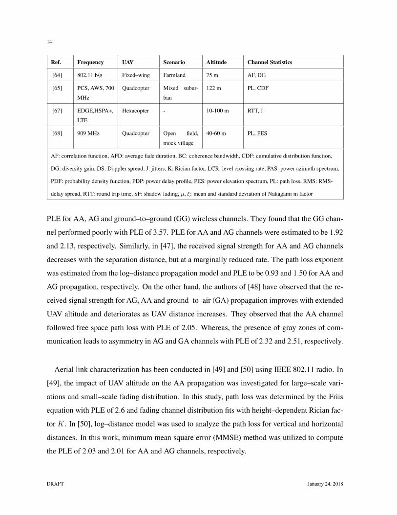
Ref. Frequency UAV Scenario Altitude Channel Statistics
[64] 802.11 b/g Fixed–wing Farmland 75 m AF, DG
[65] PCS, AWS, 700
MHz
Quadcopter Mixed subur-
ban
122 m PL, CDF
[67] EDGE,HSPA+,
LTE
Hexacopter - 10-100 m RTT, J
[68] 909 MHz Quadcopter Open field,
mock village
40-60 m PL, PES
AF: correlation function, AFD: average fade duration, BC: coherence bandwidth, CDF: cumulative distribution function,
DG: diversity gain, DS: Doppler spread, J: jitters, K: Rician factor, LCR: level crossing rate, PAS: power azimuth spectrum,
PDF: probability density function, PDP: power delay profile, PES: power elevation spectrum, PL: path loss, RMS: RMS-
delay spread, RTT: round trip time, SF: shadow fading, µ, ξ: mean and standard deviation of Nakagami m factor
PLE for AA, AG and ground–to–ground (GG) wireless channels. They found that the GG chan-
nel performed poorly with PLE of 3.57. PLE for AA and AG channels were estimated to be 1.92
and 2.13, respectively. Similarly, in [47], the received signal strength for AA and AG channels
decreases with the separation distance, but at a marginally reduced rate. The path loss exponent
was estimated from the log–distance propagation model and PLE to be 0.93 and 1.50 for AA and
AG propagation, respectively. On the other hand, the authors of [48] have observed that the re-
ceived signal strength for AG, AA and ground–to–air (GA) propagation improves with extended
UAV altitude and deteriorates as UAV distance increases. They observed that the AA channel
followed free space path loss with PLE of 2.05. Whereas, the presence of gray zones of com-
munication leads to asymmetry in AG and GA channels with PLE of 2.32 and 2.51, respectively.
Aerial link characterization has been conducted in [49] and [50] using IEEE 802.11 radio. In
[49], the impact of UAV altitude on the AA propagation was investigated for large–scale vari-
ations and small–scale fading distribution. In this study, path loss was determined by the Friis
equation with PLE of 2.6 and fading channel distribution fits with height–dependent Rician fac-
tor K. In [50], log–distance model was used to analyze the path loss for vertical and horizontal
distances. In this work, minimum mean square error (MMSE) method was utilized to compute
the PLE of 2.03 and 2.01 for AA and AG channels, respectively.
DRAFT January 24, 2018

15
TABLE II
LARGE–SCALE FADING STATISTICS FOR AA CHANNEL
Ref. PL model
[46]- [48] PL(dB) = 10α log10(d),
α= 1.922, [46], α= 0.93 [47], α= 2.05 [48]
[49] RSS(dB) = Pt +GUAV 1 +GUAV 2 + 10 log10( λ4πd
)α,
Pt= 20 dBm, GUAV 1 = GUAV 2= 5 dBi, α= 2.6, fc=2.4 GHz
[50] PL(dB) = PL(d0) + 10α log10( dd0
),
d =√d2h + d2
v , PL(d0)= 46.4 dB, α=2.03, dh ∈ 0, ..., 100m, dv= 50 m, d0= 1 m
α: path loss exponent, RSS: received signal strength, d: separation distance, d0: reference distance, dh: horizontal-
distance, dv: vertical distance, GUAV : UAV antenna gain
The AA channel characterization highlights that the propagation conditions are generally de-
termined by the vertical and horizontal distances between the multiple airborne UAVs in LOS
condition. However, significant attenuation occurs for the characterization of aerial link beyond
the LOS condition to maintain large communication range. Also it would be useful to study the
consequences of the Doppler frequency shift as the multiple UAVs cruises with higher veloci-
ties. Large–scale fading statistics of the AA channel are summarized in Table II.
B. Air–Ground (AG) Channel Characterization
1) Large–Scale Fading Statistics: Most of the AG channel measurements focus on the
large–scale statistics such as path loss exponent and shadow fading. For an urban environ-
ment in [38], the measured results exhibited that the path loss follows a distance–independent
trend and is significantly affected by the low elevation angle. The excess path loss model is
developed by extending terrestrial macro cell models that includes the reflection and diffraction
losses caused by the surrounding buildings and incorporated by the knife–edge diffraction the-
ory. For a suburban environment in [39], the impact of UAV altitude and distance on path loss
was analyzed. For UAV altitude, simplified dual slope path loss model was considered and found
that PLE is negative below the breakpoint altitude because of partially cleared first Fresnel zone,
whereas when the UAV altitude increases above the breakpoint level path loss is roughly similar
to the free space propagation due to sufficiently cleared first Fresnel zone. For horizontal UAV
January 24, 2018 DRAFT

16
distance, path loss analyzed with log–distance model. Also, in [40], the effect of UAV altitude
and the optimal placement of ground receiver on path loss was stochastically modeled for both
static and mobile UAV in an open field and suburban scenario, while considering foliage losses
and Doppler frequency shift. In addition, shadow fading is modeled with zero–mean Gaussian
distribution and analyzed with PDF. Another empirical study was conducted in [41], to evaluate
the influence of distance on path loss attenuation and found degraded performance of the AG
channel due to detrimental effect of interference from the other 802.11 devices operated in the
surrounding test area. Moreover, in [42], received signal strength declined with the distance
and followed the Friis channel model. In [43], the AG propagation channel in the single–hop
UAV system followed log–distance model, where higher throughputs were attained over longer
distance.
For an open field and campus environment in [51], path loss was evaluated with the free space
path loss model. In [52] and [53], PLE was estimated using linear regression. In [54], distance
and frequency independent empirical path loss model was proposed for urban and rural terrains,
where the altitude of aerial mobile station was accounted as the key modeling parameter. In
contrast, the empirical propagation model in [55] suggested that path loss model is dependent
on the distance in 3D plane and the operating frequency. In this case, other modeling parameters
such as the UAV altitude and the tilt angle of base station sector antenna were also considered.
The altitude dependent path loss model was proposed in [56], where path loss and shadow fad-
ing were decreased as the UAV altitude increased from 15 to 120 m and at about 100 m the
propagation condition matched to that of free space. In [57], the angle–dependent AG propaga-
tion channel model was presented, which encompasses excess path loss attenuation and shadow
fading model. In this work, the model parameters are dependent on the angle between cellular
base station and airborne UAV. The analytical path loss model was used in [65] to evaluate the
performance of LTE network with UAV platform, where most of the path loss samples computed
by measurements were lumped between the reference PLE of 2.0 and 4.0. In [68], the combina-
tional model was developed to determine the low coverage zones in the cellular–connected UAV
network. This model identified causes such as two–ray ground reflections, diffraction losses and
nulls in antenna radiation pattern as the predominant factors for path loss.
DRAFT January 24, 2018
17
Path loss and shadow fading statistics for the AG propagation channel presented in this section
demonstrated that the UAV flight dynamics, such as the altitude and distance from the ground
level, are the dominant contributors for the large–scale fading. Therefore, the development of
realistic UAV propagation model requires these parameters to be considered in 3D coordinates.
Also, considerable attention is needed for characterizing antenna design and orientations, as this
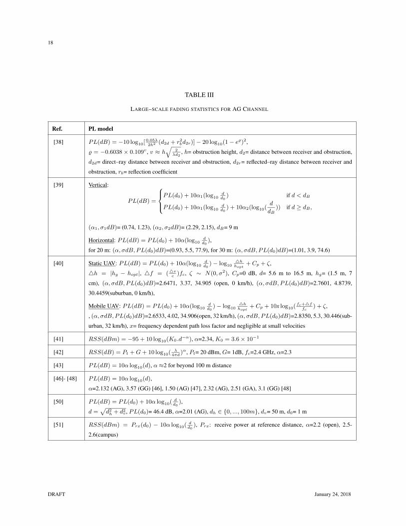
will further improve the UAV communications. In Table III, we summarize the large–scale fad-
ing statistics for the AG channel.
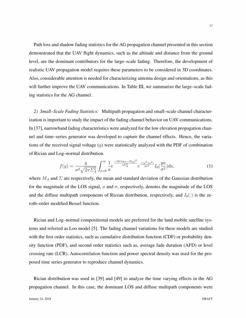
2) Small–Scale Fading Statistics: Multipath propagation and small–scale channel character-
ization is important to study the impact of the fading channel behavior on UAV communications.
In [37], narrowband fading characteristics were analyzed for the low elevation propagation chan-
nel and time–series generator was developed to capture the channel effects. Hence, the varia-
tions of the received signal voltage (y) were statistically analyzed with the PDF of combination
of Rician and Log–normal distribution.
f(y) =y
σ2√
2πΣ2A
∫ ∞a=0
1
ae−(20 log a−MA)2
2Σ2A e
−(y2+a2)
2σ2 I0(ya
σ2)da, (1)
where MA and Σ are respectively, the mean and standard deviation of the Gaussian distribution
for the magnitude of the LOS signal, a and σ, respectively, denotes the magnitude of the LOS
and the diffuse multipath components of Ricean distribution, respectively, and I0(.) is the ze-
roth–order modified Bessel function.
Rician and Log–normal compositional models are preferred for the land mobile satellite sys-
tems and referred as Loo model [5]. The fading channel variations for these models are studied
with the first order statistics, such as cumulative distribution function (CDF) or probability den-
sity function (PDF), and second order statistics such as, average fade duration (AFD) or level
crossing rate (LCR). Autocorrelation function and power spectral density was used for the pro-
posed time series generator to reproduce channel dynamics.
Rician distribution was used in [39] and [49] to analyze the time varying effects in the AG
propagation channel. In this case, the dominant LOS and diffuse multipath components were
January 24, 2018 DRAFT
18
TABLE III
LARGE–SCALE FADING STATISTICS FOR AG CHANNEL
Ref. PL model
[38] PL(dB) = −10 log10[ 0.05λ2h2 (d2d + r2
bd2r)]− 20 log10(1− e%)2,
% = −0.6038 × 0.109v , v ≈ h√
2λd2
, h= obstruction height, d2= distance between receiver and obstruction,
d2d= direct–ray distance between receiver and obstruction, d2r= reflected–ray distance between receiver and
obstruction, rb= reflection coefficient
[39] Vertical:
PL(dB) =
PL(d0) + 10α1(log10
dd0
) if d < dB
PL(d0) + 10α1(log10dd0
) + 10α2(log10(d
dB)) if d ≥ dB ,
(α1, σ1dB)= (0.74, 1.23), (α2, σ2dB)= (2.29, 2.15), dB= 9 m
Horizontal: PL(dB) = PL(d0) + 10α(log10dd0
),
for 20 m: (α, σdB, PL(d0)dB)=(0.93, 5.5, 77.9), for 30 m: (α, σdB, PL(d0)dB)=(1.01, 3.9, 74.6)
[40] Static UAV: PL(dB) = PL(d0) + 10α(log10dd0
)− log104hhopt
+ Cp + ζ,
4h = |hg − hopt|, 4f = (4vc
)fc, ζ ∼ N(0, σ2), Cp=0 dB, d= 5.6 m to 16.5 m, hg= (1.5 m, 7
cm), (α, σdB, PL(d0)dB)=2.6471, 3.37, 34.905 (open, 0 km/h), (α, σdB, PL(d0)dB)=2.7601, 4.8739,
30.4459(suburban, 0 km/h),
Mobile UAV: PL(dB) = PL(d0) + 10α(log10dd0
)− log104hhopt
+ Cp + 10x log10( fc+4ffc
) + ζ,
, (α, σdB, PL(d0)dB)=2.6533, 4.02, 34.906(open, 32 km/h), (α, σdB, PL(d0)dB)=2.8350, 5.3, 30.446(sub-
urban, 32 km/h), x= frequency dependent path loss factor and negligible at small velocities
[41] RSS(dBm) = −95 + 10 log10(K0 .d−α), α=2.34, K0 = 3.6× 10⁻¹
[42] RSS(dB) = Pt +G+ 10 log10( λ4πd
)α, Pt= 20 dBm, G= 1dB, fc=2.4 GHz, α=2.3
[43] PL(dB) = 10α log10(d), α ≈2 for beyond 100 m distance
[46]- [48] PL(dB) = 10α log10(d),
α=2.132 (AG), 3.57 (GG) [46], 1.50 (AG) [47], 2.32 (AG), 2.51 (GA), 3.1 (GG) [48]
[50] PL(dB) = PL(d0) + 10α log10( dd0
),
d =√d2h + d2
v , PL(d0)= 46.4 dB, α=2.01 (AG), dh ∈ 0, ..., 100m, dv= 50 m, d0= 1 m
[51] RSS(dBm) = Prx(d0) − 10α log10( dd0
), Prx: receive power at reference distance, α=2.2 (open), 2.5-
2.6(campus)
DRAFT January 24, 2018
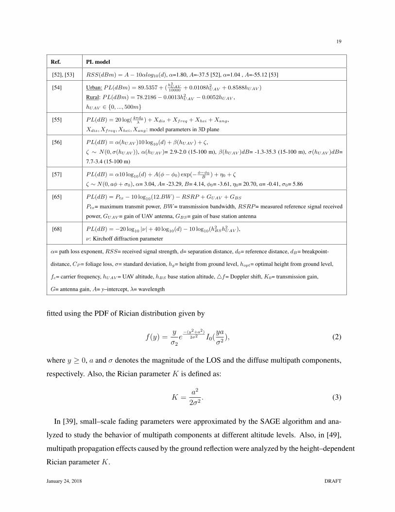
19
Ref. PL model
[52], [53] RSS(dBm) = A− 10αlog10(d), α=1.80, A=-37.5 [52], α=1.04 , A=-55.12 [53]
[54] Urban: PL(dBm) = 89.5357 + (h3UAV
10000+ 0.0108h2
UAV + 0.8588hUAV )
Rural: PL(dBm) = 78.2186− 0.0013h2UAV − 0.0052hUAV ,
hUAV ∈ 0, ..., 500m
[55] PL(dB) = 20 log( 4πd0λ
) +Xdis +Xfreq +Xhei +Xang ,
Xdis, Xfreq, Xhei, Xang: model parameters in 3D plane
[56] PL(dB) = α(hUAV )10 log10(d) + β(hUAV ) + ζ,
ζ ∼ N(0, σ(hUAV )), α(hUAV )= 2.9-2.0 (15-100 m), β(hUAV )dB= -1.3-35.3 (15-100 m), σ(hUAV )dB=
7.7-3.4 (15-100 m)
[57] PL(dB) = α10 log10(d) +A(φ− φ0) exp(−φ−φ0B
) + η0 + ζ
ζ ∼ N(0, aφ+ σ0), α= 3.04, A= -23.29, B= 4.14, φ0= -3.61, η0= 20.70, a= -0.41, σ0= 5.86
[65] PL(dB) = Ptx − 10 log10(12.BW )−RSRP +GUAV +GBS
Ptx= maximum transmit power, BW= transmission bandwidth, RSRP= measured reference signal received
power, GUAV = gain of UAV antenna, GBS= gain of base station antenna
[68] PL(dB) = −20 log10 |ν|+ 40 log10(d)− 10 log10(h2BSh
2UAV ),
ν: Kirchoff diffraction parameter
α= path loss exponent, RSS= received signal strength, d= separation distance, d0= reference distance, dB= breakpoint-
distance, CP= foliage loss, σ= standard deviation, hg= height from ground level, hopt= optimal height from ground level,
fc= carrier frequency, hUAV = UAV altitude, hBS base station altitude,4f= Doppler shift, K0= transmission gain,
G= antenna gain, A= y–intercept, λ= wavelength
fitted using the PDF of Rician distribution given by
f(y) =y
σ2e−(y2+a2)
2σ2 I0(ya
σ2), (2)
where y ≥ 0, a and σ denotes the magnitude of the LOS and the diffuse multipath components,
respectively. Also, the Rician parameter K is defined as:
K =a2
2σ2. (3)
In [39], small–scale fading parameters were approximated by the SAGE algorithm and ana-
lyzed to study the behavior of multipath components at different altitude levels. Also, in [49],
multipath propagation effects caused by the ground reflection were analyzed by the height–dependent
Rician parameter K.
January 24, 2018 DRAFT
20
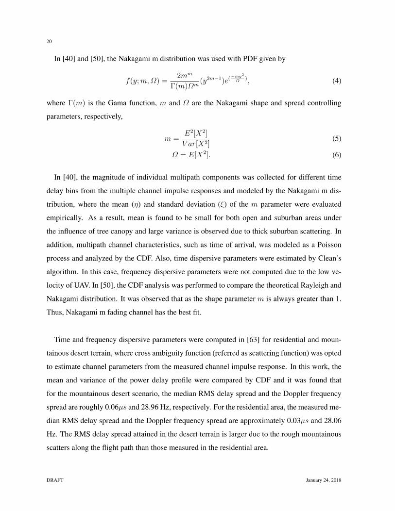
In [40] and [50], the Nakagami m distribution was used with PDF given by
f(y;m,Ω) =2mm
Γ(m)Ωm(y2m−1)e(
−my2
Ω), (4)
where Γ(m) is the Gama function, m and Ω are the Nakagami shape and spread controlling
parameters, respectively,
m =E2[X2]
V ar[X2](5)
Ω = E[X2]. (6)
In [40], the magnitude of individual multipath components was collected for different time
delay bins from the multiple channel impulse responses and modeled by the Nakagami m dis-
tribution, where the mean (η) and standard deviation (ξ) of the m parameter were evaluated
empirically. As a result, mean is found to be small for both open and suburban areas under
the influence of tree canopy and large variance is observed due to thick suburban scattering. In
addition, multipath channel characteristics, such as time of arrival, was modeled as a Poisson
process and analyzed by the CDF. Also, time dispersive parameters were estimated by Clean’s
algorithm. In this case, frequency dispersive parameters were not computed due to the low ve-
locity of UAV. In [50], the CDF analysis was performed to compare the theoretical Rayleigh and
Nakagami distribution. It was observed that as the shape parameter m is always greater than 1.
Thus, Nakagami m fading channel has the best fit.
Time and frequency dispersive parameters were computed in [63] for residential and moun-
tainous desert terrain, where cross ambiguity function (referred as scattering function) was opted
to estimate channel parameters from the measured channel impulse response. In this work, the
mean and variance of the power delay profile were compared by CDF and it was found that
for the mountainous desert scenario, the median RMS delay spread and the Doppler frequency
spread are roughly 0.06µs and 28.96 Hz, respectively. For the residential area, the measured me-
dian RMS delay spread and the Doppler frequency spread are approximately 0.03µs and 28.06
Hz. The RMS delay spread attained in the desert terrain is larger due to the rough mountainous
scatters along the flight path than those measured in the residential area.
DRAFT January 24, 2018
21
Channel characterization for small–scale fading effects mostly addresses temporal variations
and scant efforts have been put to study spatial variation. Also, for most AG propagation cases
reported, the Nakagami and Rician distributions seem to effectively analyze the fading channel
statistics.
IV. ANALYTICAL CHANNEL MODELS
Analytical channel models are useful for characterizing the propagation behavior under cer-
tain assumptions and parameters. They can predict the performance of communication systems.
For the land mobile satellite systems, channel behavior can be analyzed using the multi–state
Markov chain model [4], [5]. For the terrestrial cellular systems, there are three main model-
ing approaches: deterministic, stochastic and geometry–based stochastic approach. In the de-
terministic technique, environmental–specific parameters are utilized to model the propagation
channel. In the stochastic approach, the propagation characteristics are realized by the channel
statistics without requiring the specific location information. In the geometry–based stochastic
approach, random scatters are assumed in the environment to obtain the spatial–temporal statis-
tics in a stochastic manner by applying the deterministic or ray–tracing model. These models
can be used for UAV channels. In this section, we will categorize the UAV channel modeling
approaches reported in the literature and presents some analytical expressions of them.
A. Deterministic
In deterministic channel models, environmental clutters are placed in the certain layouts. This
approach assumes large dimensions of the environmental objects in comparison with the wave-
length, thus not compensating the diffuse scattering. The accuracy of these channel models
depends on the environment–specific database which consists of the information related to the
terrain topography, the electrical parameters of buildings and other obstruction materials. Deter-
ministic models can also be realized by the ray–tracing simulation software, which can depict
the realistic behavior of the EM wave propagation and simulate power loss and shadowing ef-
fects.
January 24, 2018 DRAFT
22
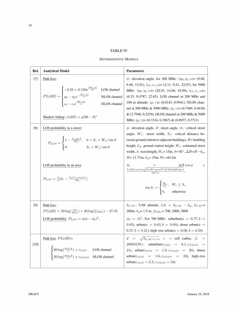
In [6], 3D ray–tracing was performed to characterize the AG propagation in the suburban en-
vironment for the channel between cellular base station and airborne UAV. Also, the well–known
macro cell terrestrial channel models were tested with the boundary conditions in order to de-
termine the applicability of low altitude aerial platforms for providing cellular coverage. In [7]
and [8], analytical propagation models have been studied for the AG channel characterization in
an urban environment for the frequency ranging from 200 MHz to 5 GHz and the aerial altitude
from 100 to 2000 m. In [7], the average path loss and shadowing statistics were examined as
the function of elevation angle and the aerial altitude through 3D ray–tracing simulations. The
authors have provided analytical path loss expressions. Also, the shadow fading was fitted with
the log–normal distribution with the standard deviation dependent on the elevation angle. In
addition, propagation conditions were determined from the simulation results and categorized
as, LOS, NLOS (non-LOS) and OLOS (obstructed LOS) channels. The work in [8] utilized
knife–edge diffraction theory to model the LOS probability, which considered the statistical
parameters to account for height, size and coverage area of buildings in the simulation environ-
ment.
In [9]– [11], environmental topography was realized with the statistical parameters recom-
mended by the International Telecommunication Union (ITU–R). In [9], a generic path loss
model in low altitude platform was proposed, where the channel model parameters were esti-
mated by the 3D ray–tracing at 700 MHz, 2000 MHz and 5800 MHz. In this work, the AG
channel conditions favoring LOS and NLOS propagations were grouped distinctly and analyzed
with the group occurrence probability as the conditional PDF. Simulation results demonstrated
that the impact of elevation angle was significant on the excess path loss.
In [10], the closed–form expressions was formulated for predicting the coverage footprint
from the aerial platform in terms of the maximum cell radius and the optimal altitude. In this
study, the free space path loss model was extended with the excessive attenuation factor and cor-
responds to LOS and NLOS propagation conditions. This was extended in [11] to provide the
analytical framework for optimization of the average radio coverage probability and the max-
imum transmission rate to achieve the required quality of service. Some of the deterministic
UAV channel models are reported in Table IV
DRAFT January 24, 2018

23
B. Stochastic Channel Model
For the UAV communication systems, stochastic based channel models can be designed us-
ing the tapped delay line (TDL) system with different numbers of taps, each of which can ac-
commodate fading statistics of the multipath components derived from the channel impulse
response. The accuracy of these model depends on the estimation of stationary interval in the
non–stationary UAV channel.
In [12]– [14], wideband stochastic channel models were proposed from the data collected
in different environments, using the estimated stationary interval of 15 m at the C band. For
the over water settings in [12], the AG channel employed the TDL model to characterize the
two–ray propagation plus an intermittent multipath component as the third ray. In this work,
the authors have argued that the statistics for LOS and reflected components can be analyzed
by either curved earth two ray (CE2R) or flat earth two ray (FE2R) model. The probability of
the existence of the intermittent multipath component was estimated by the exponential distri-
bution as a function of link distance. The TDL model with nine taps have been proposed for
the mountainous terrain [13] and an urban environment [14]. In both of these studies, seven in-
termittent multipath components were considered and the probability of existence, excess delay
and duration of intermittent multipath components were modeled as the linear function of link
range.
In [69] and [70], stochastic model was developed with the narrowband assumption to charac-
terize the aeronautical AG channel. In [69], the stochastic model was designed for characterizing
the AG propagation in terms of transmission coefficients assuming that the quadrature compo-
nents reflected from the ground surface can be modeled as a zero–mean Gaussian process. Also,
Doppler spectrum analysis was performed for the diffuse multipath components. In [70], the
proposed model was developed with the TDL system having both LOS and NLOS taps, where
the amplitude attenuation and the multipath delay of NLOS components were assumed to be
Rayleigh distributed and Gaussian random process, respectively, while the phase shift was uni-
formly distributed. Further, the Doppler frequency shift was characterized as the time varying
random process and the channel stationarity interval was not computed, but the fading statistics
January 24, 2018 DRAFT
24
TABLE IV
DETERMINISTIC MODELS
Ref. Analytical Model Parameters
[7] Path loss:
PL(dB) =
−0.58 + 0.549e
(90−φ)24 LOS channel
η0 − η1e−(90−φ)ν NLOS channel
ι0 − ι1e(90−φ)ω OLOS channel
Shadow fading: σ(dB) = ρ(90− θ)γ
φ: elevation angle, for 200 MHz: (η0, η1, ν)= (9.08,
6.40, 12.01), (ι0, ι1, ω)= (2.11, 0.41, 22.07), for 5000
MHz: (η0, η1, ν)= (20.43, 14.60, 10.50), (ι0, ι1, ω)=
(6.23, 0.4787, 22.65), LOS channel at 200 MHz and
100 m altitude: (ρ, γ)= (0.0143, 0.9941), NLOS chan-
nel at 200 MHz & 5000 MHz: (ρ, γ)= (0.7489, 0.4638)
& (2.7940, 0.2259), OLOS channel at 200 MHz & 5000
MHz: (ρ, γ)= (0.3334, 0.3967) & (0.8937, 0.3713)
[8] LOS probability in a street:
PLOS =
1− Sc sinϑWs
, 0 < Sc < Ws/ sinϑ
0, Sc > Ws/ sinϑ
φ: elevation angle, ϑ: street angle, ϑc: critical street
angle, Ws: street width, Sc: critical distance be-
tween ground station to adjacent buildings,H= building
height, hg: ground station height, We: estimated street
width, λ: wavelength,Ws= 15m, ϑ= 90, ∆H=H−hg ,
H= 11.71m, hg= 15m, We=44.2m
LOS probability in an area: Sc > ∆H cotφ +0.16λ cosφ+
√(0.16λ cosφ)2+0.32λ∆H sinφ
sin2 φ,
PLOS = 2π
[ϑc − Sc(1−cosϑc)We
]
sinϑc =
WeSc, We ≤ Sc
0, otherwise
[9] Path loss:
PL(dB) = 20 log( 4hsinφ
) + 20 log(fMHz)− 27.55
hUAV : UAV altitude, 4h = hUAV − hg , hUAV =
200m, hg= 1.5 m, fMHz= 700, 2000, 5800
LOS probability: PLOS = a(φ− φ0)b, φ0 = 15, For 700 MHz: suburban(a = 0.77, b =
0.05), urban(a = 0.63, b = 0.09), dense urban(a =
0.37, b = 0.21), high–rise urban(a = 0.06, b = 0.58)
[10]
Path loss: PL(dB)=20 log( 4πfcdc
) + εLOS LOS channel
20 log( 4πfcdc
) + εNLOS NLOS channel
d =√hUAV 2+r2 , r = cell radius, fc =
2000MHz: suburban(εLOS = 0.1, εNLOS =
21), urban(εLOS = 1.0, εNLOS = 20), dense
urban(εLOS = 1.6, εNLOS = 23), high–rise
urban(εLOS = 2.3, εNLOS = 34)
DRAFT January 24, 2018
25
TABLE V
TDL MODELS
Ref. TDL model
[12] h(τ, t) = h2−ray(τ, t) + w3(t)A3(t) exp(−jϕ3(t))δ(τ − τ3(t)),
h2−ray denotes FE2R or CE2R model, w3(t) ∈ 0, 1 represents presence/absence of third–ray and modeled
as p(d) = aebd, A3 is the amplitude of third–ray and modeled by the Gaussian distribution, ϕ3 ∈ 0, 2πis the uniformly randomly distributed phase of third–ray, τ3 is the excess delay of third–ray and modeled
as p(τ3) = 1µe−(τ3−100/µ), (a, b)=(0.17,-0.25) over sea water and (0.03,-0.15) over freshwater, µ= 17 ns,
6ns ≤ τ3 ≤ 7ns, d is the link distance
[13],
[14]
h(τ, t) = A1(t)δ(τ − τ1(t)) +A2(t) exp(−jϕ2(t))δ(τ − τ2(t)) +∑9L=3 wL(t)AL(t) exp(−jϕL(t))δ(τ −
τL(t))
A, ϕ and τ denotes amplitude, phase and excess delay, respectively, subscripts 1, 2 and L represents LOS,
reflected and Lth intermittent multipath components, respectively, variations of wL and τL are modeled as a
linear function of link range , ϕL ∈ 0, 2π is the the uniformly randomly distributed phase, 10 log(A2L
A21
)
represents relative power of intermittent components and follows a Gaussian distribution
[70] y(t) = A1(t) cos[2πfc +4f(t− τ1(t))] +∑NL=2 AL(t) cos[2πfc +4f(t− τL(t)) + ϕL(t)] + n(t)
A1 is the amplitude of LOS path, AL represents amplitude of NLOS paths and assumed as Rayleigh random
process, ϕL ∈ −π, π is the phase shift of NLOS paths and modeled as uniform random process,4f denotes
Doppler frequency shift and modeled as time–variant random process, τ1= 25µs, τL is excess delay of NLOS
components and modeled as the Gaussian random process with mean and standard deviation of 30µs and 5µs,
respectively, n(t) is white Gaussian noise
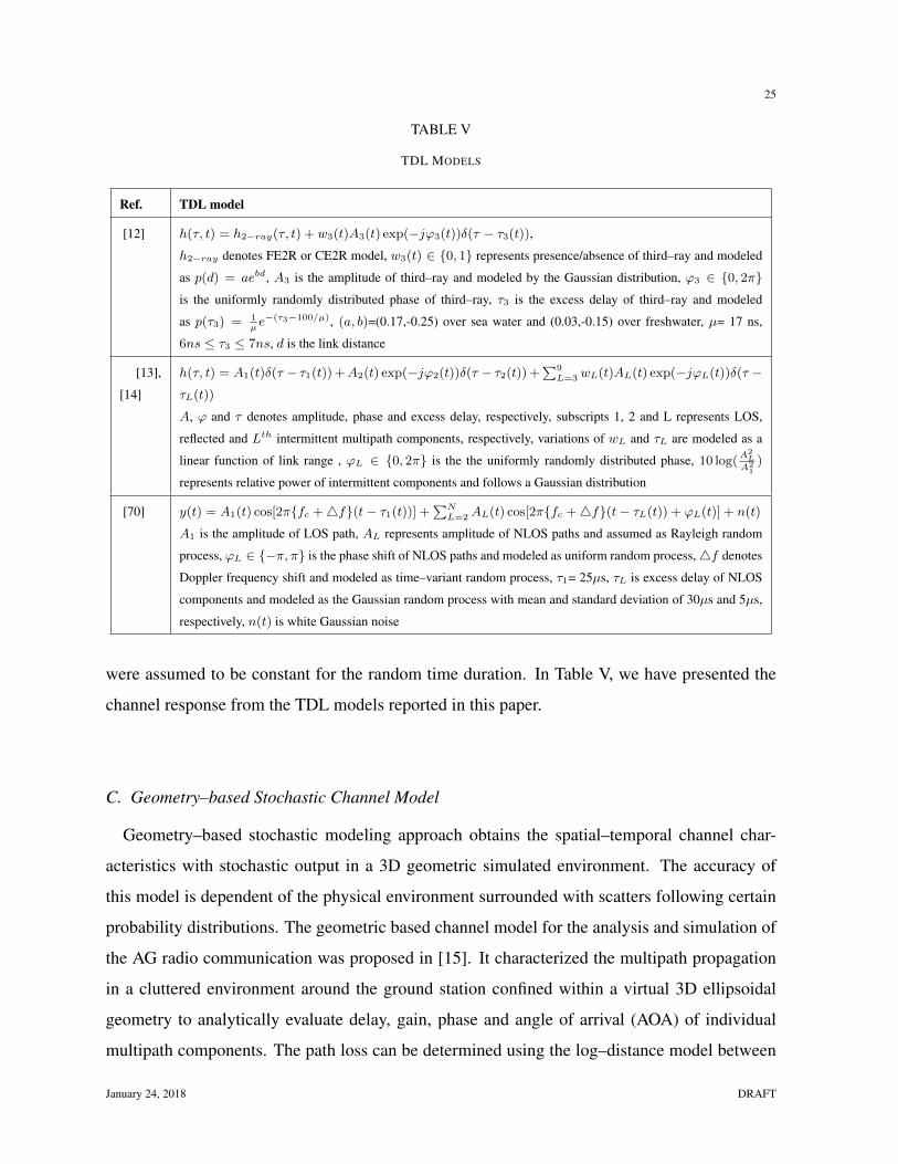
were assumed to be constant for the random time duration. In Table V, we have presented the
channel response from the TDL models reported in this paper.
C. Geometry–based Stochastic Channel Model
Geometry–based stochastic modeling approach obtains the spatial–temporal channel char-
acteristics with stochastic output in a 3D geometric simulated environment. The accuracy of
this model is dependent of the physical environment surrounded with scatters following certain
probability distributions. The geometric based channel model for the analysis and simulation of
the AG radio communication was proposed in [15]. It characterized the multipath propagation
in a cluttered environment around the ground station confined within a virtual 3D ellipsoidal
geometry to analytically evaluate delay, gain, phase and angle of arrival (AOA) of individual
multipath components. The path loss can be determined using the log–distance model between
January 24, 2018 DRAFT
26
the airborne platform and the clutters. Therefore, the proposed model is equally applicable to de-
termine both narrowband and wideband channel statistics and well suited for designing antenna
diversity system and antenna arrays. This was extended in [16] to theoretically estimate the
MIMO performance for the low altitude AG channel and also characterize the propagation loss
for LOS and multipath components using the log–distance path loss model with the log–normal
shadow fading. In this model, the small–scale spatial fading was modeled by the Ricean distri-
bution to analyze the scattering of the multipath components. Furthermore, the probability of
error was simulated for SISO system and compared with a 2 × 2 space time block coding and a
2×2 spatial multiplexing gain using maximum likelihood detection. In [17], 3D AG propagation
model was proposed for the dense scattering environment considering low altitude platform. The
model was derived for a direction of arrival and the delay dependent Doppler spectrum with the
approximation of linear distribution of the scattering point. In this work, the analytical results
were compared with the terrain based digital elevation model simulation results and found that
the terrain morphology affects the Doppler–delay spread spectrum.
In [18], a realistic 3D geometric–based stochastic model has been developed for the AG com-
munication between an airborne platform and the base station as an elevated plane. The pro-
posed model considered scattering points as uniformly distributed around the base station. In
this study, the spatial characteristics were analyzed with the closed–form analytical expressions.
In [19], geometric–based stochastic approach has been utilized for UAV channel modeling to
analytically characterize a 2 × 2 MIMO enabled AG propagation in 3D plane. In this case, the
model was developed with the assumption that the ground scatters are distributed on the cylin-
drical surface and scatter free airborne environment. Based on the proposed model, analytical
expressions were used to study the impact of elevation angle and direction of UAV movement on
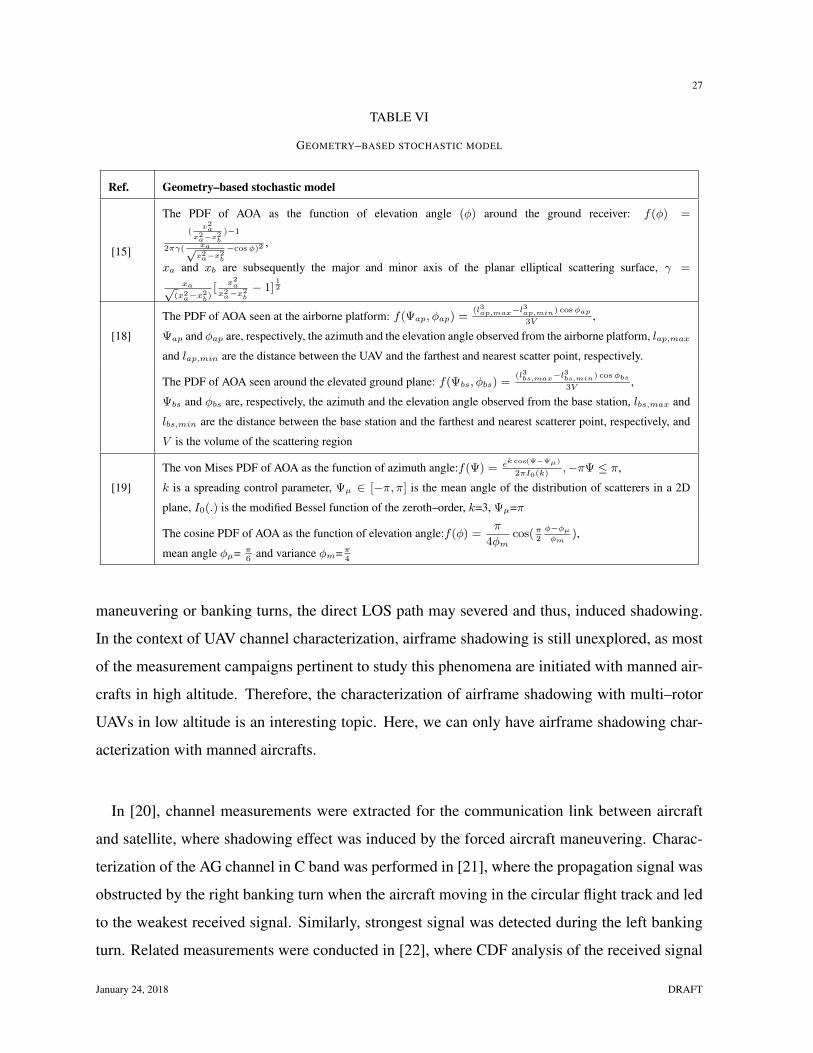
the space time correlation function in a non–isotropic environment. Some analytical expressions
to determine AOA using geometry–based model are given in Table VI.
V. IMPORTANT ISSUES
A. Airframe Shadowing
In aeronautical communication, the radio path between aircraft and ground control station
may be blocked by aircraft structure, such as wings, fuselage or engine. Also, during flight
DRAFT January 24, 2018
27
TABLE VI
GEOMETRY–BASED STOCHASTIC MODEL
Ref. Geometry–based stochastic model
[15]
The PDF of AOA as the function of elevation angle (φ) around the ground receiver: f(φ) =
(x2a
x2a−x2
b
)−1
2πγ( xa√x2a−x2
b
−cosφ)2,
xa and xb are subsequently the major and minor axis of the planar elliptical scattering surface, γ =xa√
(x2a−x2
b)[
x2a
x2a−x2
b− 1]
12
[18]
The PDF of AOA seen at the airborne platform: f(Ψap, φap) =(l3ap,max−l
3ap,min) cosφap
3V,
Ψap and φap are, respectively, the azimuth and the elevation angle observed from the airborne platform, lap,max
and lap,min are the distance between the UAV and the farthest and nearest scatter point, respectively.
The PDF of AOA seen around the elevated ground plane: f(Ψbs, φbs) =(l3bs,max−l
3bs,min) cosφbs
3V,
Ψbs and φbs are, respectively, the azimuth and the elevation angle observed from the base station, lbs,max and
lbs,min are the distance between the base station and the farthest and nearest scatterer point, respectively, and
V is the volume of the scattering region
[19]
The von Mises PDF of AOA as the function of azimuth angle:f(Ψ) = ek cos(Ψ−Ψµ)
2πI0(k),−πΨ ≤ π,
k is a spreading control parameter, Ψµ ∈ [−π, π] is the mean angle of the distribution of scatterers in a 2D
plane, I0(.) is the modified Bessel function of the zeroth–order, k=3, Ψµ=π
The cosine PDF of AOA as the function of elevation angle:f(φ) =π
4φmcos(π
2
φ−φµφm
),
mean angle φµ= π6
and variance φm=π4
maneuvering or banking turns, the direct LOS path may severed and thus, induced shadowing.
In the context of UAV channel characterization, airframe shadowing is still unexplored, as most
of the measurement campaigns pertinent to study this phenomena are initiated with manned air-
crafts in high altitude. Therefore, the characterization of airframe shadowing with multi–rotor
UAVs in low altitude is an interesting topic. Here, we can only have airframe shadowing char-
acterization with manned aircrafts.
In [20], channel measurements were extracted for the communication link between aircraft
and satellite, where shadowing effect was induced by the forced aircraft maneuvering. Charac-
terization of the AG channel in C band was performed in [21], where the propagation signal was
obstructed by the right banking turn when the aircraft moving in the circular flight track and led
to the weakest received signal. Similarly, strongest signal was detected during the left banking
turn. Related measurements were conducted in [22], where CDF analysis of the received signal
January 24, 2018 DRAFT
28
power during the circular flight track demonstrated that the airframe shadowing can be modeled
by the Gaussian distribution. The authors have observed that the shadowing effects were sub-
stantial in the circular flight track than in linear flight profile. In [23], airframe shadowing was
reported due to wings and engine of the commercial A320 aircraft, where shadowing statistics
were simulated by the finite difference time domain approach. Empirical airframe shadowing
model was proposed in [24], for analyzing shadowing loss and duration. In this study, aircraft
followed oval flight route and found that shadowing statistics were disjoint from the ground en-
vironment and link distance.
B. Stationary Interval
One of the most important characteristics that distinguish UAV communication from the con-
ventional terrestrial wireless systems is the non–stationarity in UAV channels, when the WSSUS
assumption is violated. Therefore, wideband frequency–dispersive channel statistics can possess
any significance within the stationary interval of the non–stationary UAV channel. No compre-
hensive study is available in the literature that addresses channel non–stationarity for the UAV
propagation channel in low altitude platform. Therefore, estimation of the stationary interval is
a contemporary research topic. Efforts to characterize the AG channel with stationarity interval
was performed in [60], using manned aircraft at high altitude platform. In this study, stationary
interval was computed for the wideband measurements using temporal PDP(power delay pro-
file) correlation coefficient method, whereas, spatial correlation collinearity was considered for
narrowband measurements. The estimated stationary interval from both of these methods are
approximately 15 m or 250λ at C band with 50 MHz bandwidth.
C. Diversity Gain
Diversity techniques are beneficial to enhance the reliability of the communication systems,
particularly when deep fades dominate. Diversity possibilities have been mostly exploited in
MIMO airborne communications with manned aircrafts. For example, in [25], a 4 × 4 MIMO
enabled OFDM system was used to increase the average throughput by 2 times and the range
extension by 1.6 times in comparison to a SISO system. In [26], multiple helicopter mounted
antennas were utilized to achieve the signal–to–noise (SNR) gain of approximately 13 dB. In
DRAFT January 24, 2018
29
[28], the spatial multiplexing gain was achieved with a 2 × 2 MIMO configuration and as a
consequence the throughput gain was enhanced up to 8 times for most of the flight route.
In the context of UAV communications, there are few measurement campaigns on the effect of
multiple antenna elements. In [61] and [62], the AG channel characterization was initiated with
a 1×4 antenna configuration. In this work, carrier–to–noise ratio (CNR) gain was compared for
the common combining strategies such as selection, equal–gain and maximal ratio combining
(MRC) with different antenna elements and observed that the diversity gain achieved with the
MRC method using four antenna elements is approximately 4 dB greater in an urban environ-
ment than in a wooded area under similar circumstances.
In [64], the performance of multiple receiver and transmitter nodes was evaluated by the cor-
relation coefficient. In this case, the packet delivery rate was boosted by 25% on average due
to the poor correlation at the multiple receiver nodes in a 1 × 4 configuration and by 37% with
the selection diversity using three transmitters in a 3 × 4 setup. Measurement analysis of a
4 × 4 MIMO channel in [71] revealed that despite of the sparse multipath environment, poor
spatial correlation provides the significant capacity gain due to the planar wavefronts generated
by near–field reflections at the ground receiver side. It is argued that more diversity gain could
be achieved with the robust airborne platform, constructed from the conventional aircraft mate-
rials. In this study, ground spatial characteristics were estimated by the Cosine Hermitian angle.
The diversity gain achieved by multiple antennas are dependent on the number of transmitter
and receiver antennas and the operating environment of both the UAV and the ground station.
Not enough experimental setups were designed to comprehensively characterize the viability of
these systems. Substantial research works are still required to fully recognize the benefits of
MIMO technology for both AG and AA propagation.
VI. FUTURE RESEARCH CHALLENGES
In this section, we will discuss some future research challenges for characterizing the UAV
channel with measurement campaigns and in the development of realistic UAV channel model:
January 24, 2018 DRAFT
30
• To provide seamless coverage with UAV communication in all circumstances, measurement
campaigns are required to investigate the UAV channel in dense urban environment and in
the metropolitan cities with consent from the local civil aviation regulatory bodies.
• USRP platforms can provide more flexibility to initiate UAV measurement campaigns with
wideband frequencies and low power consumption. This also allows USRP to test different
wireless communication protocols such as multi–carrier and MIMO system to be used in
UAV communication.
• The AA channel characterization is required to study the consequences of Doppler shift
experienced by multiple UAVs cruising with different velocities.
• Airframe shadowing has not received commensurate level of attention for small size rota-
tory UAVs, Therefore, measurement campaigns are required to study this phenomenon for
both AG channel in the single–hop network and AA propagation in the multi–hop network.
In addition, ray–tracing can be used to probe the airframe shadowing, as CAD tools are ca-
pable of incorporating UAV shape, metallic properties and different maneuvering positions.
• Estimation of the stationary interval is of paramount importance for characterizing the AG
channel regarding wideband frequency–selective parameters. Therefore, it would be in-
teresting to estimate channel parameters with spectral divergence [72] and evolutionary
spectrum [73] methods.
VII. CONCLUSIONS
This paper has provided a comprehensive survey of the UAV channel characterization with
measurement campaigns and statistical channel models. We have categorized the UAV channel
measurement campaigns in low altitude platform based on the narrowband or wideband chan-
nel sounder, low–cost and low–power channel sounding solution, and widely deployed ground
infrastructure. We have also reviewed empirical channel models for characterizing AG and
AA propagation channel. Then we have classified the UAV channel modeling approaches as
deterministic, stochastic and geometric–stochastic models. Further, we have examined some
challenging issues in the practicability of UAV communications related to airframe shadowing,
the channel non–stationarity, and diversity techniques. Finally we have presented some future
DRAFT January 24, 2018
31
research challenges which will be helpful to provide further insight of the UAV channel charac-
terization for launching future measurement campaigns and proposing pragmatic framework for
the effective UAV channel models.
REFERENCES
[1] Radio Technical Commission for Aeronautics (RTCA), SC-228, “Minimum Operational Performance Standards for Un-
manned Aircraft Systems”, May 2013, available online at http://www.rtca.org/content/sc-228.
[2] Radio Technical Commission for Aeronautics (RTCA), “Drone Advisory Committee (DAC)”, 2016, available online at
http://www.rtca.org/content/drone-advisory-committee.
[3] National Aeronautics and Space Administration, Oct. 2014, available online at
http://www.aeronautics.nasa.gov/isrp/uas/index. html.
[4] A. Panagopoulos, P.D.M. Arapoglou and P. Cottis, ”Satellite communications at KU, KA, and V bands: Propagation
impairments and mitigation techniques,” IEEE Commun. Surv. Tuts., vol. 6, no. 3, pp. 2-14, 2004.
[5] P. Chini, G. Giambene and S. Kota, ”A survey on mobile satellite systems,” Int. J. Satell. Commun. Networking, vol. 28,
no. 1, pp. 29-57, 2009.
[6] K. Daniel, M. Putzke, B. Dusza and C. Wietfeld, ”Three dimensional channel characterization for low altitude aerial
vehicles,” in Proc. 7th Int. Symp. Wireless Commun. Syst (ISWCS’10), York, UK, Sept. 2010, pp. 756-760.
[7] Q. Feng, J. McGeehan, E. K. Tameh and A. R. Nix, ”Path Loss Models for Air-to-Ground Radio Channels in Urban
Environments,” in Proc. IEEE Veh. Technol Conf. (VTC-Spring’06), Melbourne, Australia, May 2006, pp. 2901-2905.
[8] Q. Feng, E. K. Tameh, A. R. Nix and J. McGeehan, ”Modelling the Likelihood of Line-of-Sight for Air-to-Ground Radio
Propagation in Urban Environments,” in Proc. IEEE Global Commun. Conf. (GLOBECOM’06), San Francisco, USA, Dec.
2006, pp. 1-5.
[9] A. Al-Hourani, S. Kandeepan and A. Jamalipour, ”Modeling Air-to-Ground Path Loss for Low Altitude Platforms in Urban
Environments,” in Proc. IEEE Global Commun. Conf. (GLOBECOM’14), Austin, USA, Dec. 2014, pp. 2898-2904.
[10] A. Al-Hourani, S. Kandeepan and S. Lardner, ”Optimal LAP Altitude for Maximum Coverage,” IEEE Wireless Commun.
Lett., vol. 3, no. 6, pp. 569-572, 2014.
[11] A. Al-Hourani, S. Chandrasekharan, G. Kaandorp, W. Glenn, A. Jamalipour and S. Kandeepan, ”Coverage and Rate
Analysis of Aerial Base Stations,” IEEE Trans. Aerosp. Electron. Syst., vol. 52, no. 6, pp. 3077-3081, 2016.
[12] D.W. Matolak and R. Sun, ”Air–Ground Channel Characterization for Unmanned Aircraft Systems–Part I: Methods Mea-
surements and Models for Over-Water Settings,” IEEE Trans. Veh. Technol., vol. 66, no. 1, pp. 26-44, 2017.
[13] R. Sun and D.W. Matolak, ”Air–Ground Channel Characterization for Unmanned Aircraft Systems–Part II: Hilly and
Mountainous Settings,” IEEE Trans. Veh. Technol., vol. 66, no. 3, pp. 1913-1925, 2017.
[14] D.W. Matolak and R. Sun, ”Air–Ground Channel Characterization for Unmanned Aircraft Systems–Part III: The Suburban
and Near-Urban Environments,” IEEE Trans. Veh. Technol., vol. 66, no. 8, pp. 6607-6618, 2017.
[15] W. Newhall and J. Reed, ”A geometric air–to–ground radio channel model,” in Proc. IEEE Mil. Commun. Conf. (MIL-
COM”02), Anaheim, USA, Oct. 2002, pp. 632-636.
[16] M. Wentz and M. Stojanovic, ”A MIMO Radio Channel Model for Low-Altitude Air-to-Ground Communication Systems,”
in Proc. IEEE Veh. Technol Conf. (VTC–Fall’15), Boston, USA, Sept. 2015, pp. 1-6.
[17] M. Ibrahim and H. Arslan, ”Air–Ground Doppler–Delay Spread Spectrum for dense scattering environments,” in Proc.
IEEE Mil. Commun. Conf. (MILCOM’15), Tampa, USA, Oct. 2015, pp. 1661-1666.
January 24, 2018 DRAFT
32
[18] S. Gulfam, S. Nawaz, M. Patwary and M. Maguid, ”On the Spatial Characterization of 3-D Air-to-Ground Radio Commu-
nication Channels,” in Proc. IEEE Int. Conf. Commun. (ICC’15), London, UK, June 2015, pp. 2924-2930.
[19] L. Zeng, X. Cheng, C.X. Wang and X. Yin, ”A 3D Geometry-based Stochastic Channel Model for UAV–MIMO Channels,”
in Proc. IEEE Wireless Commun. Netw. Conf. (WCNC’17), San Francisco, USA, March 2017, pp. 1-5.
[20] M. Holzbock and C. Senninger, ”An aeronautical multimedia service demonstration at high frequencies,” IEEE Trans.
Multimedia, vol. 6, no. 4, pp. 20–29, 1999.
[21] Y. Lee, Y. Meng and Y.H. Heng, ”Experimental characterizations of an air to land channel over sea surface in C band,” in
Proc. 29th USRI General Assembly, 2008, pp. 2-5.
[22] Y.S. Meng and Y.H. Lee, ”Study of shadowing effect by aircraft maneuvering,” Int. J. Electron. Commun., vol. 66, no. 1,
pp. 7-11, 2012.
[23] J. Kunisch, I.de la Torre, A. Winkelmann, M. Eube and T. Fuss, ”Wideband time–variant air–to–ground radio channel
measurements at 5 GHz,” in Proc. 5th Eur. Conf. Antennas Propag. (EuCAP’11), Rome, Italy, April 2011, pp. 1386-1390.
[24] R.Sun and D.W. Matolak, ”Air–Ground Channel Characterization for Unmanned Aircraft Systems Part–IV: Airframe
Shadowing,” IEEE Trans. Veh. Technol., vol. 66, no. 9, pp. 7643-7652, 2017.
[25] J. Chen, B. Daneshrad and W. Zhu, ”MIMO Performance Evaluation for Airborne Wireless Communication Systems,” in
Proc. IEEE Mil. Commun. Conf. (MILCOM’11), Baltimore, USA, Nov. 2011, pp. 1827-1832.
[26] M. Rice and M. Jensen, ”Multipath Propagation for Helicopter-to-Ground MIMO Links,” in Proc. IEEE Mil. Commun.
Conf. (MILCOM’11), Baltimore, USA, Nov. 2011, pp. 447-452.
[27] M. Rice and M. Saquib, ”MIMO Equalization for Helicopter-to-Ground Communications,” in Proc. IEEE Mil. Commun.
Conf. (MILCOM’11), Baltimore, USA, Nov. 2011, pp. 501-506.
[28] Y. Jiang, A. Tiwari, M. Rachid and B. Daneshrad, ”MIMO for airborne communications [Industry Perspectives],” IEEE
Wireless Commun., vol. 21, no. 5, pp. 4-6, 2014.
[29] W. Vergara, J. Levatich and T. Carroll, ”VHF air–ground propagation far beyond the horizon and tropospheric stability,”
IRE Antennas Propag., vol. 10, no. 5, pp. 608–621, 1962.
[30] K. Chamberlin, ”The effect of tree cover on air–ground, VHF propagation path loss,” IEEE Trans. Commun., vol. 34, no.
9, pp. 958-962, 1986.
[31] J.R. Child, ”Air–to–ground propagation at 900 MHz,” in Proc. IEEE Veh. Technol Conf.(VTC–Fall’85), Colorado, USA,
May 1985, pp. 73-80.
[32] M. Rice and R. Dye, ”Narrowband channel model for aeronautical telemetry,” IEEE Trans. Aerosp. Electron. Syst., vol.
36, no. 4, pp. 1371-1376, 2000.
[33] W.G. Newhall, R. Mostafa, C. Dietrich, C.R. Anderson, G. Joshi and J.H. Reed, ”Wideband air-to-ground radio chan-
nel measurements using an antenna array at 2 GHz for low-altitude operations,” in in Proc. IEEE Mil. Commun. Conf.
(MILCOM’03), Boston, USA, Oct. 2003, pp. 1422-1427.
[34] M. Rice, A. Davis and C. Bettweiser, ”Wideband channel model for aeronautical telemetry,” IEEE Trans. Aerosp. Electron.
Syst., vol. 40, no. 1, pp. 57-69, 2004.
[35] US Department of Transportation Federal Aviation Authority, ”Integration of Civil Unmanned Air-
craft Systems (UAS) in the National Airspace System (NAS) Roadmap,” 2013, available online at
http://www.faa.gov/uas/media/uas roadmap 2013.pdf.
[36] Civil Aviation Safety Authority (CASA), “Flying drones or model aircraft recreationally”, available online at
https://www.casa.gov.au/modelaircraft.
[37] M. Simunek, F.P. Fontan and P. Pechac, ”The UAV Low Elevation Propagation Channel in Urban Areas: Statistical Anal-
ysis and Time-Series Generator,” IEEE Trans. Antennas Propag., vol. 61, no. 7, pp. 3850-3858, 2013.
DRAFT January 24, 2018

33
[38] M. Simunek, P. Pechac and F.P. Fontan, ”Excess Loss Model for Low Elevation Links in Urban Areas for UAVs,” Radio
engineering, vol. 20, no. 3, pp. 561-568, 2011.
[39] X. Cai, A.G-. Plaza, D. Alonso, L. Zhang, C.B. Rodriguez, A.P. Yuste and X. Yin, ”Low altitude UAV propagation channel
modelling,” in Proc. 11th Eur. Conf. Antennas Propag (EuCAP’17), Paris, France, March 2017, pp. 1443-1447.
[40] W. Khawaja, I. Guvenc and D. Matolak, ”UWB Channel Sounding and Modeling for UAV Air-to-Ground Propagation
Channels,” in Proc. IEEE Global Commun. Conf. (GLOBECOM’16), Washington, USA, Dec. 2016, pp. 1-7.
[41] E.W. Frew and T.X. Brown, ”Airborne Communication Networks for Small Unmanned Aircraft Systems,” Proceedings of
the IEEE, vol. 96, no. 12, pp. 2008-2027, 2008.
[42] N. Goddemeier, S. Rohde and C. Wietfeld, ”Experimental Validation of RSS Driven UAV Mobility Behaviors in IEEE
802.11s Networks,” in Proc. IEEE Global Commun. Conf. (GLOBECOM’12), Anaheim, USA, Dec. 2012, pp. 1550-1555.
[43] E. Yanmaz, S. Hayat, J. Scherer and C. Bettstetter, ”Experimental Performance Analysis of Two-Hop Aerial 802.11 Net-
works,”in Proc. IEEE Wireless Commun. Netw. Conf. (WCNC’14), Istanbul, Turkey, April 2014, pp. 3118-3123.
[44] T. Brown, B. Argrow, C. Dixon, S. Doshi, R. Thekkekunnel and D. Henkel, ”Ad-hoc UAV ground network (Augnet),” in
Proc. AIAA Unmanned Unlimited Tech. Conf., 2004, pp. 29-39.
[45] S. Hayat, E. Yanmaz and C. Bettstetter, ”Experimental Analysis of Multipoint-to-Point UAV Communications with IEEE
802.11n and 802.11ac,” in Proc. 26th IEEE Annual Intl. Symp. Personal Indoor Mobile Radio Commun. (PIMRC’15),
Hong Kong, 2015. pp. 1991-1996.
[46] J. Allred, A. B. Hasan, S. Panichsakul, W. Pisano, P. Gray and J. Huang, ”SensorFlock: An Airborne Wireless Sensor
Network of Micro-Air Vehicle,” in Proc. ACM SenSys, 2007, pp. 117–129.
[47] A. Shaw and K. Mohseni, ”A Fluid Dynamic Based Coordination of a Wireless Sensor Network of Unmanned Aerial
Vehicles: 3-D Simulation and Wireless Communication Characterization,” IEEE Sensors Journal, vol. 11, no. 3, pp. 722-
736, 2011.
[48] N. Ahmed, S. Kanhere and S. Jha, ”On the Importance of Link Characterization for Aerial Wireless Sensor Network,”
IEEE Commun. Mag., vol. 54, no. 5, pp. 52-57, 2016.
[49] N. Goddemeier and C. Wietfeld, ”Investigation of Air–to–Air Channel Characteristics and a UAV Specific Extension to
the Rice Model,” in Proc. IEEE Global Commun. Conf. (GLOBECOM’15),San Diego, USA, Dec. 2015, pp. 1-5.
[50] E. Yanmaz, R. Kuschnig and C. Bettstetter, ”Achieving Air–Ground Communications in 802.11 Networks with Three-
Dimensional Aerial Mobility,” in Proc. IEEE INFOCOM, Turin, Italy, April 2013, pp. 120-124.
[51] E. Yanmaz, R. Kuschnig and C. Bettstetter, ”Channel Measurements over 802.11a–based UAV–to–Ground Links,” in Proc.
IEEE Global Commun. Conf. (GLOBECOM’11), Houston, USA, Dec. 2011, pp. 1280-1284.
[52] C.M. Cheng, P.H. Hsiao, H. Kung and D. Vlah, ”Performance measurement of 802.11a wireless links from UAV to ground
nodes with various antenna orientations,” in Proc. Intl. Conf. Computer Comm. and Networks (ICCCN’06), Arlington,
USA, Oct. 2006, pp. 303-308.
[53] D. Hague, H. Kung and B. Suter, ”Field Experimentation of Cots-Based UAV Networking,” in Proc. IEEE Mil. Commun.
Conf. (MILCOM’06), Washington, USA, Oct. 2006, pp. 1-7.
[54] N. Goddemeier, K. Daniel and C. Wietfeld, ”Coverage Evaluation of Wireless Networks for Unmanned Aerial Systems,”
in Proc. IEEE Global Commun. Conf. (GLOBECOM’10), Miami, USA, Dec. 2010, pp. 1760-1765.
[55] T. Tavares, P. Sebastiao, N. Souto, F. Cercas, M. Ribeiro, A. Correia and F.J. Velez, ”Generalized LUI propagation model
for UAVs communications using terrestrial cellular networks,” in Proc. IEEE Veh. Technol Conf. (VTC–Fall’15), Boston,
USA, Sept. 2015, pp. 1-6.
[56] R. Amorim, H. Nguyen, P. Mogensen, I.Z. Kovacs, J. Wigard and T.B. Sorensen, ”Radio Channel Modeling for UAV
Communication Over Cellular Networks,” IEEE Wireless Commun. Lett., vol. 6, no. 4, pp. 514-517, 2017.
January 24, 2018 DRAFT
34
[57] A.Al-Hourani and K. Gomez, ”Modeling Cellular–to–UAV Path-Loss for Suburban Environments,” IEEE Wireless Com-
mun. Lett., vol. pp, no.99, 2017.
[58] L. Gupta, R. Jain and G. Vaszkun, ”Survey of Important Issues in UAV Communication Networks,” IEEE Commun. Sur.
Tut., vol. 18, no. 2, pp. 1123-1152, 2016.
[59] S. Hayat, E. Yanmaz, R. Muzaffar, ”Survey on Unmanned Aerial Vehicle Networks for Civil Applications: A Communi-
cations Viewpoint,” IEEE Commun. Sur. Tut. vol. 18, no. 4, pp. 2624-2661, 2016.
[60] D.W. Matolak, ”Air-Ground Channels and Models: Comprehensive Review and Considerations for Unmanned Aircraft
Systems,” in Proc. IEEE Aero. Conf., MT, USA, March 2012, pp. 1-17.
[61] M. Simunek, F.P. Fontan, P. Pechac and F.J.D. Otero, ”Space Diversity Gain in Urban Area Low Elevation Links for
Surveillance Applications,” IEEE Trans. Antennas Propag., vol. 61, no. 12, pp. 6255-6260, 2013.
[62] M. Simunek, P. Pechac and F.P. Fontan, ”Feasibility of UAV Link Space Diversity in Wooded Areas,” Intl. J. Antennas
Propag., vol. 2013, pp. 1-6, 2013.
[63] R.M. Gutierrez, H. Yu, Y. Rong and D.W. Bliss, ”Time and Frequency Dispersion Characteristics of the UAS Wire-
less Channel in Residential and Mountainous Desert Terrains,” in Proc. IEEE Annual Consumer Commun. Netw. Conf.
(CCNC’17), Las Vegas, USA, Jan. 2017, pp. 516-521.
[64] H.T. Kung, C.K. Lin, T.H. Lin, S.J. Tarsa and D. Vlah, ”Measuring Diversity on a Low–Altitude UAV in a Ground–to–Air
Wireless 802.11 Mesh Network,” in Proc. IEEE Global Commun. Conf. (GLOBECOM’10), Miami, USA, Dec. 2010, pp.
1799-1804.
[65] Qualcomm Technologies, Inc. ”LTE Unmanned Aircraft Systems Trial Report,”2017, available online at
https://www.qualcomm.com/documents/lte-unmanned-aircraft-systems-trial-report.
[66] Ericsson, ”Ericsson and China Mobile conduct worlds first 5G drone prototype field trial”, 2016, available
online at https://www.ericsson.com/en/news/2016/8/ericsson-and-china-mobile-conduct-worlds-first-5g-drone-prototype-
field-trial-.
[67] L. Afonso, N. Souto, P. Sebastiao, M. Ribeiro, T. Tavares and R. Marinheiro, ”Cellular for the Skies: Exploiting Mobile
Network Infrastructure for Low Altitude Air–to–Ground Communications,” IEEE Aerosp. Electron. Syst., vol. 31, no. 8,
pp. 4-11, 2016.
[68] E. Teng, J. D. Falcao and B. Iannucci, ”Holes–in–the–Sky: A Field Study on Cellular-Connected UAS,” in Proc.
(ICUAS’17), Miami, USA, June 2017, pp. 1165-1174.
[69] S. Elnoubi, ”A Simplified Stochastic Model for the Aeronautical Mobile Radio Channel,” in Proc. IEEE Vehicular Tech.
Conf. (VTC’92), Denver, USA, May 1992, vol. 2, pp. 960-963.
[70] M. A. Zaman, S. A. Mamun, M. Gaffar, M. M. Alam and M. I. Momtaz, ”Modeling VHF Air–to–Ground Multipath
Propagation Channel and Analyzing Channel Characteristics and BER Performance,” in Proc. IEEE Region 8 SIBIRCON,
Listvyanka, Russia, July 2010, pp. 335-338.
[71] T.J. Willink, C. Squires, G. Colman and M. Muccio, ”Measurement and Characterization of Low-Altitude Air-to-Ground
MIMO Channels,” IEEE Trans. Veh. Technol., vol. 65, no. 4, pp. 2637-2648, 2016.
[72] T.T. Georgiou, ”Distances and Riemannian metrics for spectral density functions,” IEEE Trans. Signal Process., vol. 55,
no. 8, pp. 3995-4003, 2007.
[73] T.J. Willink, ”Wide sense stationarity of mobile MIMO radio channels,” IEEE Trans. Veh. Technol., vol. 57, no. 2, pp.
704-714, 2008.
DRAFT January 24, 2018