A Survey and Projected Performance of Pulsed Power ... Survey and Projected Performance of Pulsed...
26
Army Research Laboratory Aberdeen Proving Ground, MD 210055066 ARL-TN-163 May 2000 A Survey and Projected Performance of Pulsed Power Supplies at Aberdeen Proving Ground, MD Alexander E. Zielinski Weapons and Materials Research Directorate, ARL Approved for public release; disttibution is unlimited.
Transcript of A Survey and Projected Performance of Pulsed Power ... Survey and Projected Performance of Pulsed...
Army Research Laboratory Aberdeen Proving Ground, MD 210055066
ARL-TN-163 May 2000
A Survey and Projected Performance of Pulsed Power Supplies at Aberdeen Proving Ground, MD
Alexander E. Zielinski Weapons and Materials Research Directorate, ARL
Approved for public release; disttibution is unlimited.
Abstract
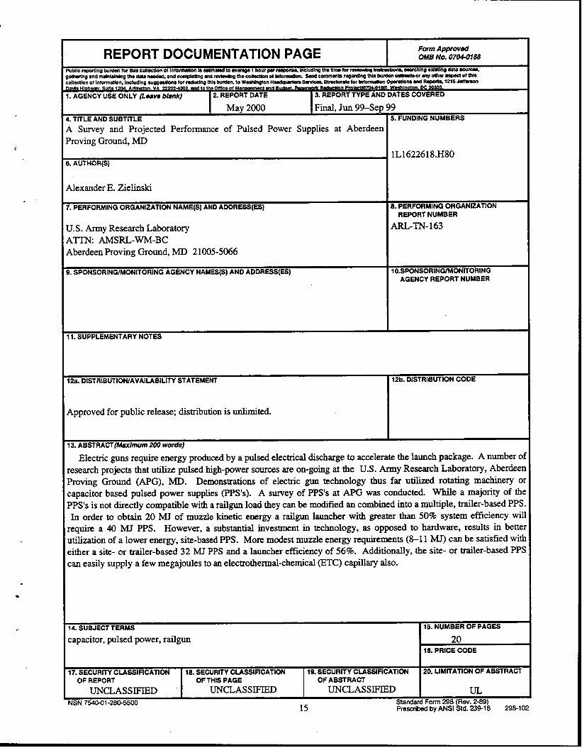
Electric guns require energy produced by a pulsed electrical discharge to accelerate the launch package. A number of research projects that utilize pulsed high-power sources are on-going at the U.S. Army Research Laboratory, Aberdeen Proving Ground (APG), MD. Demonstrations of electric gun technology thus far utilized rotating machinery or capacitor-based pulsed power supplies (PPS’s). A survey of PPS’s at APG was conducted. While a majority of the PPS’s is not directly compatible with a railgun load, they can be modified and combined into a multiple, trailer-based PPS. In order to obtain 20 MJ of muzzle kinetic energy, a railgun launcher with greater than 50% system efficiency will require a 40-MJ PPS. However, a substantial investment in technology, as opposed to hardware, results in better utilization of a lower energy, site-based PPS. More modest muzzle energy requirements (8-11 MJ) can be satisfied with either a site- or trailer-based 32-N PPS and a launcher efficiency of 56%. Additionally, the site- or trailer-based PPS can easily supply a few Megajoules to an electrothermal-chemical (ETC) capillary as well.
‘
.
.
ii
c
Acknowledgments
Funding for this effort was provided by the Electric Armaments Program Office, U.S. Army
Research Laboratory (ARL), Aberdeen Proving Ground, MD. Additionally, helpful technical
discussions were provided by the following colleagues: Gary Katulka, Mike Keele, Paul
Beming, Hardev (Dave) Singh, Miguel DelGuercio (ARL); L. Francis, Aberdeen Test Center
(ATC); Brad Goodell, United Defense Limited Partnership (UDLP); Tim Wolfe, Jeffery
Kezerian, Maxwell Laboratories Inc. (MLI); William Davis, Tom Coradeschi, U.S. Army
Armament Research, Development, and Engineering Center
Singh (ARL) provided a technical review of the manuscript.
(ARDEC). Finally, Dr. Hardev
. . . 111

hTENTIONALLY LEFT BLANK
iV
Table of Contents
Page
1.
2.
3.
4.
4.1 Performance ........................................................................................................ 6 4.2 costs .................................................................................................................... 7 4.3 Investment Strategy ............................................................................................. 8
5.
6. References ..,.............................................~............................................................... 11
Acknowledgments . . . . . . . . . . . . . . . . . . . . . . . . . . . . . . . . . . . . . . . . . . . . . . . . . . . . . . . . . . . . . . . . . . . . . . . . . . . . . . . . . . . . . . . . . . . . . . . . . . . .
List of Figures . . . . . . . . . . . . . . . . . . . . . . . . . . . . . . . . . . . . . . . . . . . . . . . . . . . . . . . . . . . . . . . . . . . . . . . . . . . . . . . . . . . . . . . . . . . . . . . . . . . . . . . . . .
. . . 111
vii
List of Tables . . . . . . . . . . . . . . . . . . . . . . . . . . . . . . . . . . . . . . . . . . . . . . . . . . . . . . . . . . . . . . . . . . . . . . . . . . . . . . . . . . . . . . . . . . . . . . . . . . . . . . . . . . . vii
Introduction ............................................................................................................. 1
Pulsed Power Supply Survey .................................................................................. 1
Projected Performance ........................................................................................... 4
Packaging and Operation ....................................................................................... 6
Summary and Conclusions ..................................................................................... 10
Distribution List . . . . . . . . . . . . . . . . . . . . . . . . . . . . . . . . . . . . . . . . . . . . . . . . . . . . . . . . . . . . . . . . . . . . . . . . . . . . . . . . . . . . . . . . . . . . . . . . . . . . . . 13
Report Documentation Page . . . . . . . . . . . . . . . . . . . . . . . . . . . . . . . . . . . . . . . . . . . . . . . . . . . . . . . . . . . . . . . . . . . . . . . . . . . . . . . . . . 15
V

.
INTENTIQNALLYLEFFBLANK
vi

List of Figures
Figure Pane
1. Illustration of Typical PPS Load Current Waveforms . . . . . . . . . . . . . . . . . . . . . . . . . . . . . . . . . . . . . . . . . . . . . . 2
2. 60-MJ PPS Solutions . . . . . . . . . . . . . . . . . . . . . . . . . . . . . . . . . . . . . . . . . . . . . . . . . . . . . . . . . . . . . . . . . . . . . . . . . . . . . . . . . . . . . . . . . . . . . . . . . 7
3. Investment Strategy . . . . . . . . . . . . . . . . . . . . . . . . . . . . . . . . . . . . . . . . . . . . . . . . . . . . . . . . . . . . . . . . . . . . . . . . . . . . . . . . . . . . . . . . . . . . . . . . . . . 9
List of Tables
Table Page
1. Summary of Capacitor-Based PPS’s at APG, MD ................................................... 3
2. High-Performance Railgun Tests at the Green Farm Facility ................................... 4
3. Summary of Projected Performance ......................................................................... 5
Y
vii

INTENTIONALLYLEFTBLANK
. . . Vlll
1. Introduction
.
t
Electric guns require energy produced by a pulsed electrical discharge to accelerate the
launch package. Some electric guns use chemicals as the primary form of energy and therefore
require a relatively small amount of electrical energy. Electromagnetic launchers, specifically
railguns, use electrical power exclusively. Consequently, they require a more substantial supply.
All electric guns utilize a tailored discharge current waveform. Therefore, the design of the
pulse-forming network (PFN), is crucial in obtaining the desired performance.
A number of research projects that utilize pulsed high-power sources are ongoing at the U.S.
Army Research Laboratory (ARL,), Aberdeen Proving Ground (APG), MD. They include
railguns [ 1, 21, electrothermal-chemical guns [3-51, coilguns [6], semiconductors [7], and
electromagnetic armor [S, 91. Each research team conducts small- and large-scale research with
separate, individual pulsed power supplies (PPS’s). Additionally, the Aberdeen Test Center
(ATC), also located at APG, has a research facility for conducting pulsed power experiments
[lo]. A survey was conducted to estimate the total amount
Only those PPS’s with greater than 0.4 MJ are considered.
of stored capacitive energy at APG.
This technical note addresses the extent to which the individual PPS’s are useable when
integrated together. Also discussed are the shortfalls and remedies to obtain 20 MJ of total
kinetic energy from an electromagnetic railgun. Finally, a strategy is presented by which 20 MJ
of muzzle energy and more modest performance (8 and 11 MJ) can be assessed relative to the
available PPS ‘s.
2. Pulsed Power Supply Survey
A total of 11 capacitor-based PPS’s were identified at APG, of which 2 are specifically
designed to provide current to a railgun. The remaining PPS’s are deficient. In some cases,
components may even be missing from the PPS. For example, a coilgun and armor load do not
1
typically utilize a discrete inductor incorporated into the PFN. In the case of a coilgun, the
propulsive device (i.e., an inductor) provides for sufficient pulse shaping. In the case of an
armor load, a large current with a very short rise time limits the amount of inductance that can be
tolerated in the PFN. Still, for some armor loads, electrical discharge switches may even be
omitted, due to the interaction of the penetrator (either a shaped charge jet or heavy metal alloy)
and armor plates. Moreover, a railgun PPS by design does not meet the rise time requirements
for an armor load, regardless of the amount of energy stored in the PPS. Crowbar diodes used to
prevent voltage reversal across the capacitors are equally important to provide for a near constant
current to the railgun, but they are not entirely necessary for electrothermal-chemical (EYE),
coilgun, and armor loads. In a few PPS’s, they are not incorporated. The disparity between load
current waveforms, for different applications and therefore PPS design specifications, is
illustrated in Figure 1.
‘Iime (ms)
‘&we 1. Illustration of Typical BPS Load Current Waveforms.
Generally, a PPS for railgun operation can be used, albeit not at the highest efficiency, with
all other load types. The converse is not true since railguns require high currents and they
usually complicate the design of the PFN components (e.g., the number of diodes required,
stresses on conductors, etc.).
.
.
Essentially, the only common component in the survey is the capacitor. While this
component is certainly vital for a PPS, it is by no means the only component. Considerable
effort is involved in converting the nonrailgun PPS’s to function with a railgun load. These
include upgrading (or adding) PFN inductors that are capable of conducting the increased
currents, upgrading (or adding) semiconductor diodes to deliver the proper pulse-shape,
upgrading (or adding) fuses on the capacitors, and upgrading (or adding) discharge switches. A
majority of the PPS’s, nearly one-half the total available energy, are not immediately compatible
with a railgun load.
Additionally, a PPS operational prior to 1999 will require, at a minimum, some maintenance
to reestablish routine operation. Resources will be proportional to the amount of time that the
PPS has not been operated. Nearly one-half the number of facilities surveyed will require
resources to reestablish routine operation. Collectively, these facilities also represent the
majority of the energy storage capacity in this survey. A summary of the relevant characteristics
from the PPS survey is listed in Table 1.
Table 1. Summary of Capacitor-Based PPS’s at APG, MD
Facility Descriptor
freen Far-ma
Maximum Capacitor Stored Primary Voltage Recent
POC Location Energy Load Rating Operation (MI) (kv>
T. Wolfe (MU? San Diego, 32.0 Railgun 11 1999
kesently under consideration for installation and operation at APG. vlaxwell Laboratories Inc., San Diego, CA.
’ Presently under construction; expected operation is 2000 [9].
3
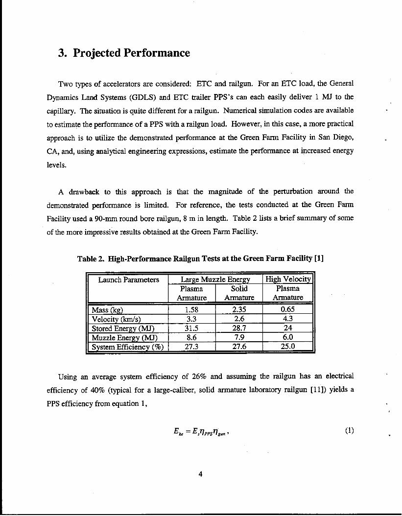
3. Projected Performance
Two types of accelerators are considered: ETC and railgun. For an ETC load, the General
Dynamics Land Systems (GDLS) and ETC trailer PPS’s can each easily deliver 1 MJ to the
capillary. The situation is quite different for a railgun. Numerical simulation codes are available
to estimate the performance of a PPS with a railgun load. However, in this case, a more practical
approach is to utilize the demonstrated performance at the Green Farm Facility in San Diego,
CA, and, using analytical engineering expressions, estimate the performance at increased energy
levels.
A drawback to this approach is
demonstrated performance is limited.
that the magnitude of the perturbation around the
For reference, the tests conducted at the Green Farm
Facility used a 90-mm round bore railgun, 8 m in length. Table 2 lists a brief summary of some
of the more impressive results obtained at the Green Fatm Facility.
Table 2. High-Performance Railgun Tests at the Green Farm Facility [ II
Launch Parameters Large Muzzle Energy Plasma Solid
High Velocity Plasma
Mass (kg) Velocity (km/s) Stored Energv fMJJ
Armature 1.58 3.3
31.5
Armature 2.35 2.6
28.7
Armature
0.65 4.3 24
Muzzle Energy (MJ) 8.6 7.9 6.0 System Efficiency (%) 27.3 27.6 25.0 \
Using an average system efficiency of 26% and assuming the railgun has an electrical
efficiency of 40% (typical for a large-caliber, solid armature laboratory railgun [ 111) yields a
PPS efficiency from equation 11,
4
.
of -65%. This efficiency takes into account sequentially discharging the modules to obtain a
near constant current to the railgun.
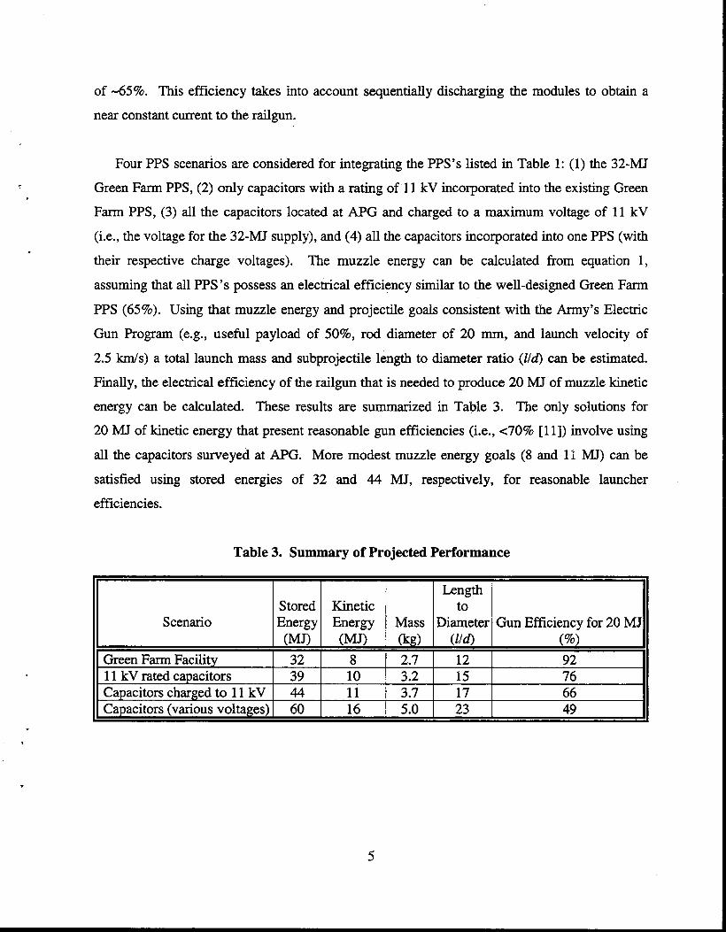
Four PPS scenarios are considered for integrating the PPS’s listed in Table 1: (1) the 32-N
Green Farm PPS, (2) only capacitors with a rating of 11 kV incorporated into the existing Green
Farm PPS, (3) all the capacitors located at APG and charged to a maximum voltage of 11 kV
(i.e., the voltage for the 32-MJ supply), and (4) all the capacitors incorporated into one PPS (with
their respective charge voltages). The muzzle energy can be calculated from equation 1,
assuming that all PPS’s possess an electrical efficiency similar to the well-designed Green Farm
PPS (65%). Using that muzzle energy and projectile goals consistent with the Army’s Electric
Gun Program (e.g., useful payload of SO%, rod diameter of 20 mm, and launch velocity of
2.5 km/s) a total launch mass and subprojectile length to diameter ratio (Z/6) can be estimated.
Finally, the electrical efficiency of the railgun that is needed to produce 20 MJ of muzzle kinetic
energy can be calculated. These results are summarized in Table 3. The only solutions for
20 INJ of kinetic energy that present reasonable gun efficiencies (i.e., ~70% [ 111) involve using
all the capacitors surveyed at APG. More modest muzzle energy goals (8 and 11 MJ) can be
satisfied using stored energies of 32 and 44 MJ, respectively, for reasonable launcher
efficiencies.
Table 3. Summary of Projected Performance
Lwe Stored Kinetic to
Scenario Energy Energy Mass Diameter Gun Efficiency for 20 MJ (MJ) (MJ) (kg) (W (%)
Green Farm Facility 32 8 2.7 12 92 11 kV rated capacitors 39 10 3.2 15 76 Capacitors charged to 11 kV 44 11 3.7 17 66 Canacitors (various voltazes) 60 16 5.0 23 49
5
4. Packaging and Operation
4.1 Performance. The amount of stored energy required to achieve 20 MJ of total kinetic
energy is nearly equal to the energy at the U.S. Army Armament Research, Development, and
Engineering Center (ARDEC) Facility, Electric Armaments Research Center (EARC), Picatinny
Arsenal, NJ [ 121. The floor space for this PPS is 60 ft x 40 ft and 18 ft high. Packaging 60 MJ
into trailers (8 ft x 48 ft) requires an assumption about the amount of energy that can be
integrated into a trailer. Four power supplies are available for data (three previous and one
recent). They are the U.S. Army, 9-MJ Pulse Power Module (PPM) 1131, the United Defense
Limited Partnership 1 l-MJ PPS [ 14, 151, the 4-MJ PPS for ETC investigations [3, 161, and the
incomplete 4-MJ Armor PPS [9]. While each effort is different, each provides an estimate of the
amount of stored capacitive energy that can be integrated into a trailer. For example, the PPM
stores 9 MJ; however, there was considerable custom hardware and significant integration in this
effort. The 4-MJ ETC PPS used commercial off-the-shelf (COTS) components; however, some
custom integration was necessary to utilize one trailer for the PPS. A second trailer was
necessary to contain the high-voltage charging power supply (HYCPS) and prime power. Still,
the armor PPS is the most recent effort and is able to take advantage of prior efforts as well as
available ARL hardware.
For a multiple, trailer-based PPS, a few assumptions are necessary to evaluate the technical
merits. It is assumed that the trailers are arranged behind the breech of a railgun and that the four
closest trailers (symmetrically arranged) have a PPS with an efficiency of 65%. The efficiency
of each subsequent trailer is then reduced by 4% to account for the increase in cable lengths to
reach the railgun breech. Certainly, the number of cables can be increased to compensate for the
losses; however, the large number of trailers and spacing makes the cabling untenable at the
breech connection.
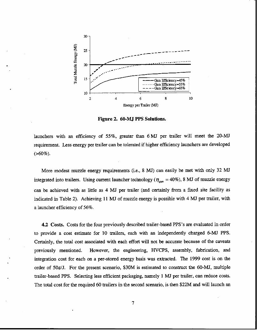
Shown in Figure 2 is the total muzzle kinetic energy as a function of the stored energy per
trailer. The effect of increased losses is clearly evident for large numbers of trailers (i.e., low
energy per trailer). Also indicated are curves for various values for launcher efficiency. For
.
6
c
.
_--- _______--- _L-
cd e_--
r/- ____ _..--_. -- . . - _ _ . . . / . / )_.-
__---- .
_.-- _*
.- /--piEsi& .- .-
.-
2 4 6 8 10
Energy per Trailer (MJ)
Figure2. 60-MJPPS Solutions.
launchers with an efficiency of 55%, greater than 6 MJ per trailer will meet the 20-MJ
requirement. Less energy per trailer can be tolerated if higher efficiency launchers are developed
(>60%).
More modest muzzle energy requirements (i.e., 8 MJ) can easily be met with only 32 MJ
integrated into trailers. Using current launcher technology ( qgun = 40%), 8 MJ of muzzle energy
can be achieved with as little as 4 MJ per trailer (and certainly from a fixed site facility as
indicated in Table 2). Achieving 11 MJ of muzzle energy is possible with 4 MJ per trailer, with
a launcher efficiency of 56%.
4.2 Costs. Costs for the four previously described trailer-based PPS’s are evaluated in order
to provide a cost estimate for 10 trailers, each with an independently charged 6-MJ PPS.
Certainly, the total cost associated with each effort will not be accurate because of the caveats
previously mentioned. However, the engineering, HVCPS, assembly, fabrication, and
integration cost for each on a per-stored energy basis was extracted. The 1999 cost is on the
order of 5Oe/J. For the present scenario, $30M is estimated to construct the 60-MJ, multiple
trailer-based PPS. Selecting less efficient packaging, namely 1 MJ per trailer, can reduce costs.
The total cost for the required 60 trailers in the second scenario, is then $22M and will launch an
7
Z/d - 9 subprojectile, less then the performance for the site-based 32-MJ Green Farm Facility (see
Table 3). Roughly one-half of the total cost is expended in hardware, of which roughly 20% is
devoted to the cost of the capacitors. Costs would increase accordingly if the surveyed
capacitors were not integrated into the mobile, trailer-based PPS. Of the one-half of the total
cost expended in labor, roughly 25% is allocated to the design of the PPS, with the balance for
fabrication and assembly.
i
Costs not accounted for and over the long-term may exceed the amount to construct the
trailer-based PPS, including the costs of not conducting competing high-energy experiments (i.e.,
scheduling conflicts) and experiments that would otherwise occur had the capacitors not been
integrated into the trailer-based PPS. Trailers with an integrated HVCPS help eliminate
competing, smaller energy experiments. The time to set up and disconnect the PPS will also
increase for each experiment, since the equipment will need to be thoroughly checked for loose
connections caused by trailer movement. Costs associated with training and operating the PPS
are also not included.
Costs for integrating less stored energy (e.g., 32 MJ) into either a site- or trailer-based PPS,
as outlined previously, will be similar to the 60-MJ PPS, albeit less. For example, a 32-W PPS
is estimated to cost !$12-16M. If all hardware were provided, assembly, trailers, and some
fabrication are expected to cost no more than $5M.
4.3 Investment Strategy. For this scale in resources, it is instructive to look at investing in
technology rather than in hardware. The Green Farm Facility provides a basis for comparison,
since it is the largest operational PPS used in railgun experiments. Technology is correlated with
gun and useful payload efficiencies. Gun efficiency will increase by extending solid armature
operation to 2.5 km/s, recovering the barrel magnetic energy and using transposed rail
conductors [ 111. Integrating composites in sabots will increase useful payload efficiency [ 171.
A portion of these increases in efficiency will naturally occur as a result of various ongoing
development programs and is accounted for.
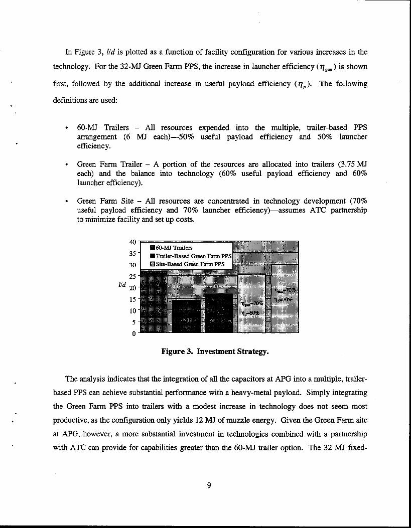
In Figure 3, Z/d is plotted as a function of facility configuration for various increases in the
technology. For the 32h4J Green Farm PPS, the increase in launcher efficiency (q,,) is shown
first, followed by the additional increase in useful payload effkiency (vp). The following
definitions are used:
.
l 60-MJ Trailers - All resources expended into the multiple, trailer-based PPS arrangement (6 MJ each)-50% useful payload efficiency and 50% launcher efficiency.
l Green Farm Trailer - A portion of the resources are allocated into trailers (3.75 hJ.J each) and the balance into technology (60% useful payload efficiency and 60% launcher efficiency).
l Green Farm Site - All resources are concentrated in technology development (70% -_ useful payload efficiency and 70% launcher efficiency)-assumes to minimize facility and set up costs.
AT6 partnership
40
35
30
25
ltd 20
15
10
5
0
figure 3. Investment Strategy.
The analysis indicates that the integration of all the capacitors at APG into a multiple, trailer-
based PPS can achieve substantial performance with a heavy-metal payload. Simply integrating
the Green Farm PPS into trailers with a modest increase in technology does not seem most
productive, as the configuration only yields 12 M.? of muzzle energy. Given the Green Farm site
at APG, however, a more substantial investment in technologies combined with a partnership
with ATC can provide for capabilities greater than the 60-MJ trailer option. The 32 MJ fixed-
9
site facility also preserves the integrity of the other PPS’s. A detailed cost-benefit analysis is
beyond the scope of this effort.
The Green Farm Facility, with 32 IW of energy storage capability, was designed,
constructed, and operational within one year Cl]. A 60-MJ, trailer-based PPS, based on existing S
data [3, 5, 9, 13, 141 with available hardware and resources, should certainly be operational
within a three-year period of time. .
5. Summary and Conclusions
A survey was conducted of capacitor-based PPS’s at APG, MD. While a majority of the
PPS’s are not directly compatible with a railgun load, they can be modified and combined into a
multiple, trailer-based PPS. The majority of the PPS’s have not been operated recently and they
will, in any even4 require resources to support routine operation.
In order to obtain 20 MJ of muzzle kinetic energy, a railgun launcher with greater than 50%
efficiency is required, as well as 44 MJ of stored electrical energy. However, a substantial
investment in technology, as opposed to hardware, results in better utilization of the lower
energy, site-based, 32-N Green Farm PPS. No increase in launcher efficiency is required to
achieve more modest muzzle energy requirements (i.e., 8 MJ) from either the site- or trailer-
based configurations. Slightly larger muzzle energy (11 MJ) requires a launcher efficiency of
56%. Additionally, the 32-&U Green Farm Facility can easily supply a few MJs to an ETC
capillary.
10
1.
2.
3.
4.
5.
6.
7.
8.
9.
10.
11.
12.
6. References
McNab, I., F. Levine, M. Aponte, and J. Hewitt. “Experiments With the Green Farm Electric Gun Facility.” IEEE Transactions on Magnetics, January 1993.
Zielinski, A., P. Weinacht, D. Webb, K. Soencksen. “An Investigation of the Ballistic Performance for an Electromagnetic Gun-Launched Projectile.” ARL-TR-1361, U.S. Army Research Laboratory, Aberdeen Proving Ground, MD, June 1997.
Katulka, G., M. DelGuercio, R. Pastore, D. Singh, and R. Burdalski. “A 4-MJ Mobile Pulse Power Facility For Electrothermal-Chemical Gun Research.” Proceedings of the 10th IEEE Pulsed Power Conference, July 1995.
DelGuercio, M., H. Burden, I. Stobie, K. White, G. Katulka, and S. Driesen. “A Pulse Forming Network Design for Electrothermal-Chemical (ETC) Combustion Characterization of Solid Propellants.” ARL-MR-261, U.S. Army Research Laboratory, Aberdeen Proving Ground, MD, September 1995.
Bhasavanich, D., D. Strachan, and R. Ford. “4.5 MJ Modular Pulse Power Supply for ET Gun Applications.” Proceedings of the 8th IEEE, Pulsed Power Conference, 1993.
Beming, P., C. Hummer, and C. Hollandsworth. “Performance of Two Electromagnetic Plate Launchers.” U.S. Army Research Laboratory Technical Report, Aberdeen Proving Ground, MD, in review.
Singh, D. “‘Survivability Concepts Branch Program Review.” WMRD, U.S. Army Research Laboratory, Aberdeen Proving Ground, MD, September 1997.
Hollandsworth, C., J. Powell, M. Keele, and C. Hummer. “Conduction in Electrically Exploded Wires of Nonuniform Diameters” ARL-TR-1773, U.S. Army Research Laboratory, Aberdeen Proving Ground, MD, December 1998.
Keele, M. Private communication. U.S. Army Research Laboratory, Aberdeen Proving Ground, MD, July 1999.
Francis, L. Fact sheet for the Aberdeen Test Center General Research Support Facility, Aberdeen Proving Ground, MD, 1993.
Bauer, D. “Achieving High Efficiency With Conventional Railgun Launchers.” IEEE Transactions on Magnetics, vol. 31, no, 1, January 1995.
Chang, D., K. Luu, L. Tran, T. Coradeschi, and B. Long. “Performance of the 52 MJ Power Supply at the Electric Armaments Research Center.” IEEE Transactions on Magnetics, vol. 31, no. 1, January 1995.
11
13.
14.
15.
16.
17.
Goode& B., and R. Ricci. “BTlYArmy Pulse Power Module.” IEEE Transactions on Mugnetics3 vol. 29, no. 1, January 1993.
Pfenning, T., C. Marinos, T. Howard, M. Hendrickson, and J. Hargreaves. “Mobile Pulse Power Systems for Electric Gun Tests.” IEEE Transactions on Magnetics, vol. 29, no. 1, January 1993.
Goodell, B. Private cornrnunication. United Defense Limited Partnership (UDLP), Minneapolis, MN, September 1999.
Singh, D. Private communication. U.S. Army Research Laboratory, Aberdeen Proving Ground, MD, September 1999.
Bums, B., L. Burton, and W. Drysdale. “Methodologies for Forecasting Sabot Mass for Advanced Gun and Projectile Systems.” BRL-TR-3387, U.S. Army Ballistic Research Laboratory, Aberdeen Proving Ground, MD, September 1992.
12
NO. OF ORGANIZATION COPIES
2 DEFENSE TECHNICAL INFORMATION CENTER DTIC DDA 8725 JOHN J KINGMAN RD STE 0944 FT BELVOIR VA 22060-62 18
1 HQDA DAMOFDQ D SCHMIDT 400 ARMY PENTAGON WASHINGTON DC 203 10-0460
1 OSD OUSD(A&T)/ODDDR&E( RJTREW THE PENTAGON WASHINGTON DC 20301-7100
1 DPTY CG FOR RDA us ARMY MATERIEL CMD AMCRDA 5001 EISENHOWER AVE ALEXANDRIA VA 22333-0001
1 INST FOR ADVNCD TCHNLGY THE UNIV OF TEXAS AT AUSTIN PO BOX 202797 AUSTIN TX 78720-2797
1 DARPA B KASPAR 3701 N FAIRFAX DR ARLINGTON VA 22203-1714
1 NAVAL SURFACE WARFARE CTR CODE B07 J PENNELLA 17320 DAHLGREN RD BLDG 1470 RM 1101 DAHLGREN VA 22448-5 100
1 US MILITARY ACADEMY MATH SC1 CTR OF EXCELLENCE DEPT OF MATHEMATICAL SC1 MADN MATH THAYERHALL WEST POINT NY 10996-1786
NO. OF COPIES
1
13
ORGANIZATION
DIRECTOR US ARMY RESEARCH LAB AMSRL D DRSMJTH 2800 POWDER MJLL RD ADELPHI MD 20783-l 197
DIRECTOR US ARMY RESEARCH LAB AMSRL DD 2800 POWDER MILL RD ADELI’HI MD 20783-l 197
DIRECTOR US ARMY RESEARCH LAB AMSRL CS AS (RECORDS MGMT) 2800 POWDER MILL RD ADELPHI MD 20783- 1145
DIRECTOR US ARMY RESEARCH LAB AMSRL CI LL 2800 POWDER MILL RD ADELPHI MD 20783-l 145
ABERDEEN PROVING GROUND
DIR USARL AMSRL CI LP (BLDG 305)
NO. OF ORGANIZATION COPIES
ABERDEEN PROVING GROUND
1 DIR USAATC CSTE DTC AT TC I
L FIWNCIS
5 DIR USARL AMSRL-W-M-TA
MKEELE AMSRL-WM-BA
GKATULKA AMSRL-W-M-TE
P BERNING H SINGH
AMSRL-WM-BE M DELGUERCIO
.
REPORT DOCUMENTATION PAGE Fm Approved OMB No. 07044188
ected Performance of Pulsed Power Supplies at Aberdeen
lL1622618.H80
J.S. Amy Research Laboratory \lTN: AMSRL-WM-BC Aberdeen Proving Ground, MD 2 10055066
AGENCY REPORT NUMBER
II. SUPPLEMENTARY NOTES
12a. DISTRIBUTION/AVAILABlLlTY STATEMENT 12b. DISTRIBUTION CODE
Approved for public release; distribution is unlimited.
13. ABSTRACT(Maximum 200 words)
Electric guns require energy produced by a pulsed electrical discharge to accelerate the launch package. A number of yesearch projects that utilize pulsed high-power sources are on-going at the U.S. Army Research Laboratory, Aberdeen Proving Ground (APG), MD. Demonstrations of electric gun technology thus far utilized rotating machinery or :apacitor based pulsed power supplies (PPS’s). A survey of PPS’s at APG was conducted. While a majority of the PPS’s is not directly compatible with a railgun load they can be modified an combined into a multiple, trailer-based PPS. In order to obtain 20 MJ of muzzle kinetic energy a railgun launcher with greater than 50% system efficiency wil;
require a 40 MJ PPS. However, a substantial investment in technology, as opposed to hardware, results in better utilization of a lower energy, site-based PPS. More modest muzzle energy requirements (8-l 1 MJ) can be satisfied witi either a site- or trailer-based 32 MJ PPS and a launcher efficiency of 56%. Additionally, the site- or trailer-based PPS :an easily supply a few megajoules to an electrothermal-chemical (ETC) capillary also.
14. SUBJECT TERMS
capacitor, pulsed power, railgun 15. NUMBER OF PAGES
20 16. PRICE CODE
17. SECURlTY CLASSIFICATION ia SECURITY CLASSIFICATION IS. SECURITY CLASSIFICATION 20. LIMITATION OF ABSTRACT OF REPORT OF THIS PAGE OF ABSTRACT
UNCLASSIFIED UNCLASSIPIED UNCLASSIFIED UL NSN 7!UU-l1-3fXLSFinO Standard Form 298 (Rev. 2-89) __. . _ _ _ ___ ____
15 hcribed by ANSI std. 239-18 298-102

INTENTIQNALLYLEFTBLANK
16

USER EVALUATION SHEET/CHANGE OF ADDRESS
This Laboratory undertakes a continuing effort to improve the quality of the reports it publishes. Your comments/answers to the items/questions below will aid us in our efforts.
1. AFtL Report Number/Author ARL-TN- 163 (ZielinsId) Date of Report Mav 2000
2. Date Report Received
i-
3. Does this report satisfy a need? (Comment on purpose, related project, or other area of interest for which the report will be used.)
_ 4. Specitically, how is the report being used? (Information source, design data, procedure, source of ideas, etc.)
5. Has the information in this report led to any quantitative savings as far as man-hours or dollars Saved, operating costs
avoided, or efficiencies achieved, etc? If so, please elaborate.
6. General Comments. What do you think should be changed to improve future reports? (Indicate changes to organization, technical content, format, etc.)
Organization
CURRENT ADDRESS
Name
Street or P-0. Box No.
E-mail Name
City, State, Zip Code
7. If indicating a Change of Address or Address Correction, please provide the Current or Correct address above and the Old
or Incorrect address below.
t
OLD ADDRESS
Organization
Name
Street or P-0. Box No.
City, State, Zip Code
(Remove this sheet, fold as indicated, tape closed, and mail.) (DO NOT STAPLE)
DEPARTMENTOFTHEARMY
OFRCIAL BUSINESS
POSTAGE WILL BE PAID BY ADDRESSEE
DIRECTOR US ARMY RESEARCH LABORATORY All-N AMSRL WM BC ABERDEEN PROVING GROUND MD 210054066