A Study on Reducing Casting Defects Leading to Water ...
9
ENGINEER 37 ENGINEER - Vol. LIV, No. 01, pp. [37-45], 2021 © The Institution of Engineers, Sri Lanka A Study on Reducing Casting Defects Leading to Water Leakage of Sand Casted Water Pump Tashi Dawa, Tashi Lhamo and G.I.P. De Silva Abstract: Casting is one of the useful processes in producing products from utensils to machinery components. However, major disadvantage of this process is accompanying of casting defects, which bring great loss to the industry. Casting defects occur due to various parameters which are hard to control under the industrial environment. Many researchers have conducted investigations to find the best combination of process parameters which causes minimum casting defects. Some of them have successfully reduced the casting defects below 5% by varying the moulding sand properties. Local pump manufacturers are currently suffering from drawbacks in production of grey cast iron water pump casings due to high rate of sand casting defects that is around 10% which leads to water leakage. This research focuses on analysis of these casting defects quantitatively and qualitatively, and their causes and suggesting effective solutions. It was found that shrinkage and blowholes are two critical defects leading to water leakage of water pump casing. Generally, it is well known that moulding sand properties, metal pouring temperature, design of gating system and chemical composition of the raw material are vital factors that lead to the formation of casting defects. The influence of these major factors on formation of shrinkage and blowholes was studied. The experimental results showed that improper design of gating system and deviation of the moulding sand properties relative to the moulding sand prepared for castings dominantly affect the shrinkage and blowhole defects. Keywords: Water pump casing, Casting defects, Moulding sand properties, Pouring temperature, Gating system 1. Introduction Although other industries in the world have already transformed to semi-automation or fully automation systems, the majority of foundries still practice the traditional manufacturing process. The requirement of a Technical Needs Assessment (TNA) to bridge the gaps related to modern technology is a crucial need [1]. There is an urgent need to enhance the quality of water pump casings produced in local major industries and other small-scale foundries, as it is not up to the competent level with international market. There is a major issue of higher casting rejections due to some chronic defects which eventually lead to water leakage. Water pump casings having completely free of water leakages, strength and hardness up to the required level and low surface roughness, are considered as castings with improved quality in terms of industrial requirement. Preparation of the green moulds following traditional methods, low quality of metal scraps, insufficient knowledge to calculate and allocate the required number of risers and runners, unawareness of the importance of controlling of liquid metal pouring temperature and cooling rate could be considered as the major causes for the defects in pump casings [1]. Unfortunately, most of the foundries have given less priority for minimizing of rejections as they focus more on reaching their existing targets [2]. There have been reports on reducing of casting defects in water pump components and other related items significantly, by proper control of moulding sand properties [3][4][5]. Defect free castings with minimum production cost have become the significant need of the foundry industry. Therefore, it is important to identify the root causes and respective remedies to reduce casting defects [5]. Thus, this research Mr. Tashi Dawa, B.Sc. Eng. (Hons) (Moratuwa), Email: [email protected] ORCID ID: https://orcid.org/0000-0002-3568-070X Miss. Tashi Lhamo, B.Sc. Eng. (Hons) (Moratuwa), Email: [email protected] ORCID ID: https://orcid.org/0000-0001-5885-076X Eng. (Dr.) G.I.P. De Silva, CEng., MIE(SL), B.Sc. Eng. (Hons) (Moratuwa) M.Phil. (Moratuwa), Ph.D. (Kochi, Japan), Senior Lecturer, Department of Materials Science and Engineering, University of Moratuwa. Email: [email protected] ORCID ID: https://orcid.org/0000-0002-8792-3494 DOI: http://doi.org/10.4038/engineer.v54i1.7433
Transcript of A Study on Reducing Casting Defects Leading to Water ...
ENGINEER37
ENGINEER - Vol. LIV, No. 01, pp. [37-45], 2021© The Institution of Engineers, Sri LankaENGINEER - Vol. LIV, No. 01, pp. [page range], 2021© The Institution of Engineers, Sri Lanka
1 ENGINEER
A Study on Reducing Casting Defects Leading to Water Leakage of Sand Casted Water Pump
Tashi Dawa, Tashi Lhamo and G.I.P. De Silva
Abstract: Casting is one of the useful processes in producing products from utensils to machinery components. However, major disadvantage of this process is accompanying of casting defects, which bring great loss to the industry. Casting defects occur due to various parameters which are hard to control under the industrial environment. Many researchers have conducted investigations to find the best combination of process parameters which causes minimum casting defects. Some of them have successfully reduced the casting defects below 5% by varying the moulding sand properties. Local pump manufacturers are currently suffering from drawbacks in production of grey cast iron water pump casings due to high rate of sand casting defects that is around 10% which leads to water leakage. This research focuses on analysis of these casting defects quantitatively and qualitatively, and their causes and suggesting effective solutions. It was found that shrinkage and blowholes are two critical defects leading to water leakage of water pump casing. Generally, it is well known that moulding sand properties, metal pouring temperature, design of gating system and chemical composition of the raw material are vital factors that lead to the formation of casting defects. The influence of these major factors on formation of shrinkage and blowholes was studied. The experimental results showed that improper design of gating system and deviation of the moulding sand properties relative to the moulding sand prepared for castings dominantly affect the shrinkage and blowhole defects.
Keywords: Water pump casing, Casting defects, Moulding sand properties, Pouring temperature, Gating system
1. Introduction
Although other industries in the world have already transformed to semi-automation or fully automation systems, the majority of foundries still practice the traditional manufacturing process. The requirement of a Technical Needs Assessment (TNA) to bridge the gaps related to modern technology is a crucial need [1].
There is an urgent need to enhance the quality of water pump casings produced in local major industries and other small-scale foundries, as it is not up to the competent level with international market. There is a major issue of higher casting rejections due to some chronic defects which eventually lead to water leakage. Water pump casings having completely free of water leakages, strength and hardness up to the required level and low surface roughness, are considered as castings with improved quality in terms of industrial requirement.
Preparation of the green moulds following traditional methods, low quality of metal scraps, insufficient knowledge to calculate and allocate the required number of risers and runners, unawareness of the importance of
controlling of liquid metal pouring temperature and cooling rate could be considered as the major causes for the defects in pump casings [1].
Unfortunately, most of the foundries have given less priority for minimizing of rejections as they focus more on reaching their existing targets [2]. There have been reports on reducing of casting defects in water pump components and other related items significantly, by proper control of moulding sand properties [3][4][5]. Defect free castings with minimum production cost have become the significant need of the foundry industry. Therefore, it is important to identify the root causes and respective remedies to reduce casting defects [5]. Thus, this research
Mr. Tashi Dawa, B.Sc. Eng. (Hons) (Moratuwa), Email: [email protected] ORCID ID: https://orcid.org/0000-0002-3568-070X
Miss. Tashi Lhamo, B.Sc. Eng. (Hons) (Moratuwa), Email: [email protected] ORCID ID: https://orcid.org/0000-0001-5885-076X
Eng. (Dr.) G.I.P. De Silva, CEng., MIE(SL), B.Sc. Eng. (Hons) (Moratuwa) M.Phil. (Moratuwa), Ph.D. (Kochi, Japan), Senior Lecturer, Department of Materials Science and Engineering, University of Moratuwa. Email: [email protected] ORCID ID: https://orcid.org/0000-0002-8792-3494
DOI: http://doi.org/10.4038/engineer.v54i1.7433
ENGINEER 38ENGINEER 2
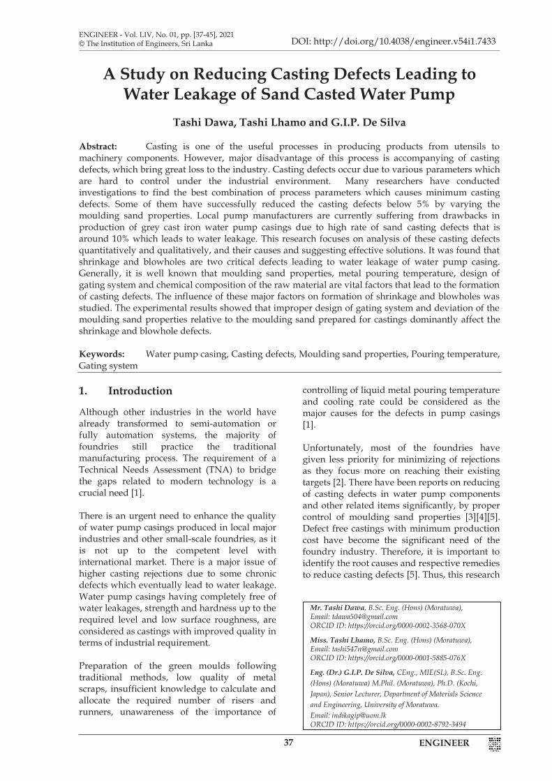
focused on finding the critical defects those contribute to the water leakage of water pump casing and finding optimum corrective measures for respective defects through both qualitative and quantitative analysis considering casting process parameters, i.e., moulding sand properties, metal pouring temperature, design of gating system and chemical composition of the raw material. 2. Methodology 2.1 Analysis of Defects A set of 40 defected water pump casings having water leakages were randomly selected for the analysis of defects. In this case, water leakage was confirmed by applying the standard water pressure testing [6]. Water supply was set to the pump through a hose and water pressure was slowly increased up to 3 bars, and kept at this pressure for a time period of 3 minutes, then water leakage was assured. The positions that water leakage occurred in all selected samples were subjected to visual inspection, macroscopic inspection using an optical microscope and Digital Radiographic testing specially to observe internal defects. Different types of defects observed for each sample were tabulated systematically.
2.2 Verification of the Effect of Chemical Composition of Scraps
A set of five randomly selected pump casings with water leakage and another set without water leakage were subjected to chemical analysis using Atomic Emission Spectroscopy. Small pieces from all 10 pump casings, especially from the positions that water leakage occurred, were obtained and samples having the size of 2x2 cm were prepared for this test. Lathe machining process was used to cut all the
samples as there is no significant effect on the microstructure due to less heating effect. All samples were heat treated at 7500C for one hour and then quenched in water prior to the chemical analysis as these are graphite cast iron specimens. 2.3 Verification of the Effect of
Microstructure on Formation of Defects
Five samples from each set of water pumps were obtained for the microstructure analysis. Samples from the positions that water leakage occurred were taken especially for the set of defected water pumps. Microstructure of these grey cast iron samples was examined by means of optical microscope. Samples were ground, polished and etched in Picral solution for 10 seconds [7] prior to microstructural observation. 2.4 Verification of the Effect of Pouring
Temperature on Formation of Defects A set of 10 pump casings were fabricated using same scrap set (chemical composition was assured for randomly selected portions of this set) and same green moulding sand mixture under fixed gating system those are associated with pump casings without water leakage. However, making these factors constant do not perfectly happen in the industrial environment. In this experiment, metal pouring temperature was measured for all 10 cases using a gun type digital thermocouple. 2.5 Analysis of the Effect of Moulding
Sand Properties on Formation of Defects
In the general production line, moulding sand batches used for producing each pump casing were tracked. Five moulding sand samples from different sand batches corresponding to defected pump casings and another 5 sand samples from sand batches of good pump casings were obtained for testing of properties such as mould hardness, green compression strength, permeability, shatter index, moisture content and clay content. All the tests were performed as per the American Foundry Society (AFS) standards.
Areas where water
leakages occurred during water
pressure testing
Figure 1 - Visual Inspection of Defects in Areas Where Water Leakage Occurred
ENGINEER39ENGINEER 2
focused on finding the critical defects those contribute to the water leakage of water pump casing and finding optimum corrective measures for respective defects through both qualitative and quantitative analysis considering casting process parameters, i.e., moulding sand properties, metal pouring temperature, design of gating system and chemical composition of the raw material. 2. Methodology 2.1 Analysis of Defects A set of 40 defected water pump casings having water leakages were randomly selected for the analysis of defects. In this case, water leakage was confirmed by applying the standard water pressure testing [6]. Water supply was set to the pump through a hose and water pressure was slowly increased up to 3 bars, and kept at this pressure for a time period of 3 minutes, then water leakage was assured. The positions that water leakage occurred in all selected samples were subjected to visual inspection, macroscopic inspection using an optical microscope and Digital Radiographic testing specially to observe internal defects. Different types of defects observed for each sample were tabulated systematically.
2.2 Verification of the Effect of Chemical Composition of Scraps
A set of five randomly selected pump casings with water leakage and another set without water leakage were subjected to chemical analysis using Atomic Emission Spectroscopy. Small pieces from all 10 pump casings, especially from the positions that water leakage occurred, were obtained and samples having the size of 2x2 cm were prepared for this test. Lathe machining process was used to cut all the
samples as there is no significant effect on the microstructure due to less heating effect. All samples were heat treated at 7500C for one hour and then quenched in water prior to the chemical analysis as these are graphite cast iron specimens. 2.3 Verification of the Effect of
Microstructure on Formation of Defects
Five samples from each set of water pumps were obtained for the microstructure analysis. Samples from the positions that water leakage occurred were taken especially for the set of defected water pumps. Microstructure of these grey cast iron samples was examined by means of optical microscope. Samples were ground, polished and etched in Picral solution for 10 seconds [7] prior to microstructural observation. 2.4 Verification of the Effect of Pouring
Temperature on Formation of Defects A set of 10 pump casings were fabricated using same scrap set (chemical composition was assured for randomly selected portions of this set) and same green moulding sand mixture under fixed gating system those are associated with pump casings without water leakage. However, making these factors constant do not perfectly happen in the industrial environment. In this experiment, metal pouring temperature was measured for all 10 cases using a gun type digital thermocouple. 2.5 Analysis of the Effect of Moulding
Sand Properties on Formation of Defects
In the general production line, moulding sand batches used for producing each pump casing were tracked. Five moulding sand samples from different sand batches corresponding to defected pump casings and another 5 sand samples from sand batches of good pump casings were obtained for testing of properties such as mould hardness, green compression strength, permeability, shatter index, moisture content and clay content. All the tests were performed as per the American Foundry Society (AFS) standards.
Areas where water
leakages occurred during water
pressure testing
Figure 1 - Visual Inspection of Defects in Areas Where Water Leakage Occurred
3 ENGINEER
Table 1 - Sand Properties Testing Machines
Testing Property Testing Machine Mould hardness
Keelson mould hardness tester (Model: 13-RC)
Green compression strength
RIDSDALE-DIETERT hand operated Universal sand strength machine (Model: 32 USSM)
Permeability Kelson electric permeability meter (Model: 27-EPM)
Shatter index Ridsdale shatter index tester (Model: 30-SIT)
Moisture content
Ohaus MB27 moisture analyser (Model: MB27)
Clay content Clay content testing machine (Model: 4-RSW)
2.6 Analysis of the Effect of Gating
System on Formation of Defects In the general production line, gating systems of the moulds used for producing each pump casing were tracked. Two sets of moulds comprising five for each, corresponding to good and defected pump casings, were selected to analyse their gating system parameters, i.e., sprue design, ingate diameter, runner length and gating ratio. All these parameters were recalculated/designed based on the standard AFS formulas/equations and compared with the existing values/designs. 3. Results and Discussions 3.1 Identification of Major Types of
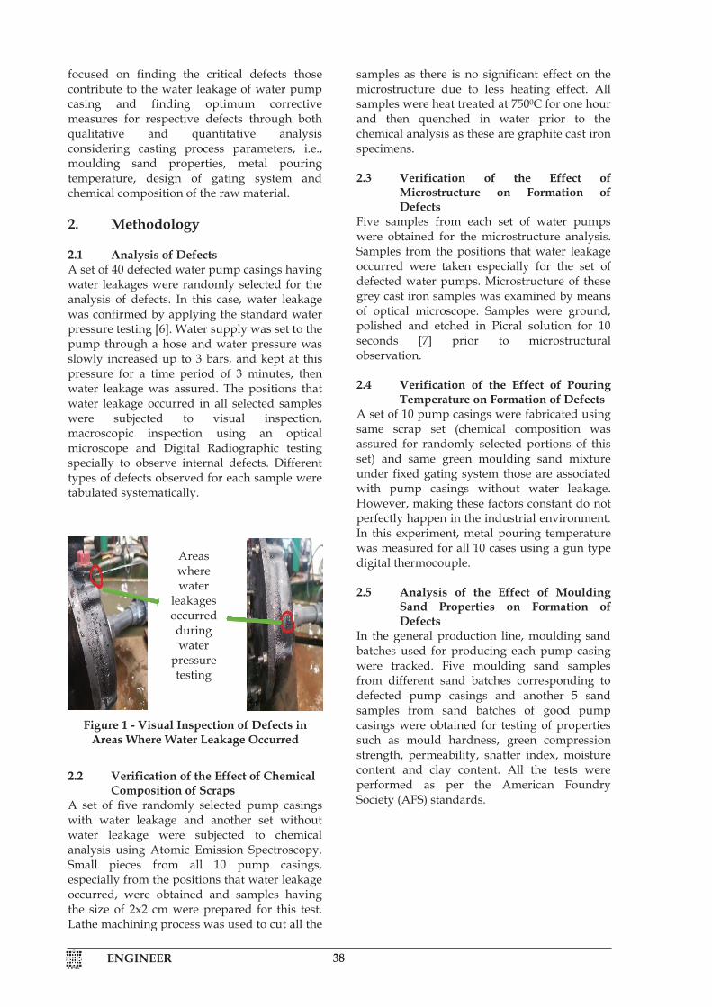
Defects Different types of defects - blow hole, shrinkage, inclusions, mismatches, hot spots, cracks, pin holes were observed in randomly selected set of 40 water pump casings having water leakage. Mostly occurred defect types were taken into account in Pareto analysis. According to the Pareto analysis charts shown
in Figure 2, blow hole and shrinkage were identified as major defects which critically contribute to the water leakage.
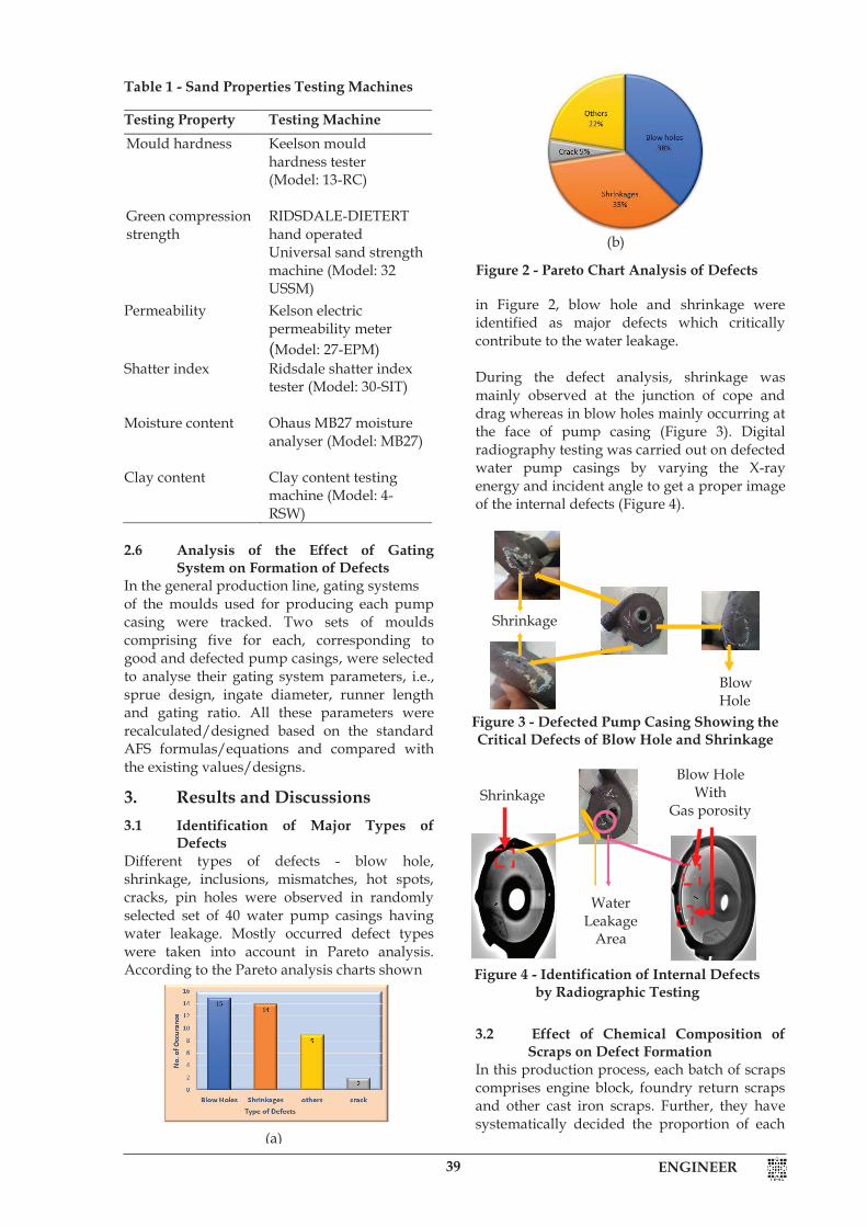
During the defect analysis, shrinkage was mainly observed at the junction of cope and drag whereas in blow holes mainly occurring at the face of pump casing (Figure 3). Digital radiography testing was carried out on defected water pump casings by varying the X-ray energy and incident angle to get a proper image of the internal defects (Figure 4).
3.2 Effect of Chemical Composition of
Scraps on Defect Formation In this production process, each batch of scraps comprises engine block, foundry return scraps and other cast iron scraps. Further, they have systematically decided the proportion of each
Blow Hole With
Gas porosity Shrinkage
Water Leakage
Area
Figure 4 - Identification of Internal Defects by Radiographic Testing
Figure 2 - Pareto Chart Analysis of Defects
Shrinkage
Blow Hole
Figure 3 - Defected Pump Casing Showing the Critical Defects of Blow Hole and Shrinkage
(b)
(a)
ENGINEER 40ENGINEER 4
component as engine blocks and foundry return scraps in weight, 23.5% and 17.6%, respectively. Steel is added if the carbon equivalent is lower than the range of 4.3 - 4.7. Other cast iron scraps, like sheets and wires, are added around 58% in order to set the required chemical composition for the grey cast iron. The chemical composition of scraps greatly affects the quality of castings, i.e., degree of formation of defects and level of mechanical properties. It was found that there was no significant difference between the chemical composition of good and defected samples and all the compositions were in the acceptable range as shown in Table 2. Therefore, it was concluded that there is no influence from the chemical composition on formation of defects.
Relatively higher Carbon content of the grey cast iron, i.e., 3.2 to 3.4 wt%, leads to formation of flake graphite also results in better fluidity of the melt [8]. Flake graphite has an expanding property which compensates for the defects of shrinkage and gas holes. However, when carbon content increases beyond 3.4 wt%, spiky/chunky graphite is formed from the graphite flakes which causes dramatic reduction in the mechanical properties as the spikes provide points of weakness in the structure [8]. Sulphur favours formation of iron sulphide which prevents the formation of graphite. Further, it increases the viscosity of the melt. Therefore, manganese is added to form manganese sulphide slag and overcome the effect of sulphur. However, manganese content needs to be added within the accepted range as it encourages the formation of cementite instead of graphite. Under these circumstances, silicon is added to promote carbon to precipitate as graphite [9]. Therefore, it is obvious that, because of the positive and
negative effects of each element in the composition, it is required to keep these contents of elements as shown in Table 2. 3.3 Effect of Microstructure on Formation
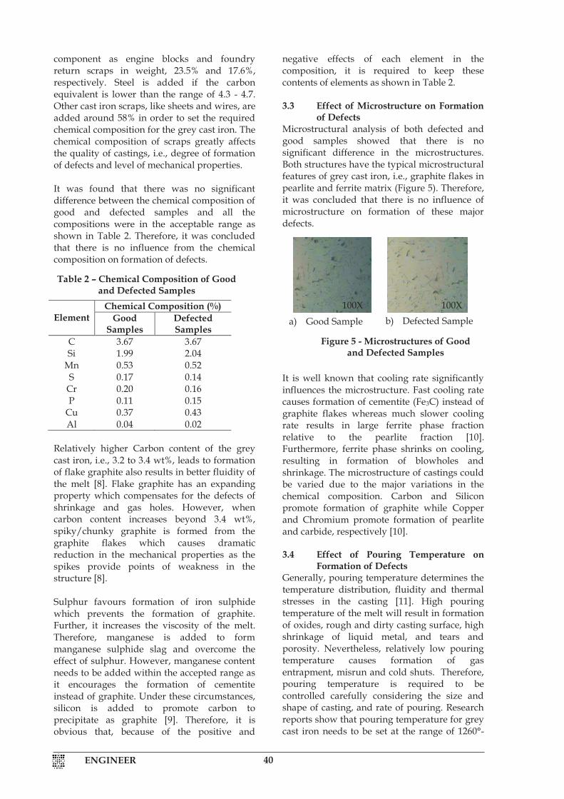
of Defects Microstructural analysis of both defected and good samples showed that there is no significant difference in the microstructures. Both structures have the typical microstructural features of grey cast iron, i.e., graphite flakes in pearlite and ferrite matrix (Figure 5). Therefore, it was concluded that there is no influence of microstructure on formation of these major defects.
It is well known that cooling rate significantly influences the microstructure. Fast cooling rate causes formation of cementite (Fe3C) instead of graphite flakes whereas much slower cooling rate results in large ferrite phase fraction relative to the pearlite fraction [10]. Furthermore, ferrite phase shrinks on cooling, resulting in formation of blowholes and shrinkage. The microstructure of castings could be varied due to the major variations in the chemical composition. Carbon and Silicon promote formation of graphite while Copper and Chromium promote formation of pearlite and carbide, respectively [10]. 3.4 Effect of Pouring Temperature on
Formation of Defects Generally, pouring temperature determines the temperature distribution, fluidity and thermal stresses in the casting [11]. High pouring temperature of the melt will result in formation of oxides, rough and dirty casting surface, high shrinkage of liquid metal, and tears and porosity. Nevertheless, relatively low pouring temperature causes formation of gas entrapment, misrun and cold shuts. Therefore, pouring temperature is required to be controlled carefully considering the size and shape of casting, and rate of pouring. Research reports show that pouring temperature for grey cast iron needs to be set at the range of 1260°-
Element
Chemical Composition (%) Good
Samples Defected Samples
C 3.67 3.67 Si 1.99 2.04
Mn 0.53 0.52 S 0.17 0.14
Cr 0.20 0.16 P 0.11 0.15
Cu 0.37 0.43 Al 0.04 0.02
Table 2 – Chemical Composition of Good and Defected Samples
a) Good Sample
b) Good Sample
(Etched)
b) Defected Sample
c) Defected Sample
(Etched)
100X 100x
Figure 5 - Microstructures of Good and Defected Samples
100X 100x
ENGINEER41ENGINEER 4
component as engine blocks and foundry return scraps in weight, 23.5% and 17.6%, respectively. Steel is added if the carbon equivalent is lower than the range of 4.3 - 4.7. Other cast iron scraps, like sheets and wires, are added around 58% in order to set the required chemical composition for the grey cast iron. The chemical composition of scraps greatly affects the quality of castings, i.e., degree of formation of defects and level of mechanical properties. It was found that there was no significant difference between the chemical composition of good and defected samples and all the compositions were in the acceptable range as shown in Table 2. Therefore, it was concluded that there is no influence from the chemical composition on formation of defects.
Relatively higher Carbon content of the grey cast iron, i.e., 3.2 to 3.4 wt%, leads to formation of flake graphite also results in better fluidity of the melt [8]. Flake graphite has an expanding property which compensates for the defects of shrinkage and gas holes. However, when carbon content increases beyond 3.4 wt%, spiky/chunky graphite is formed from the graphite flakes which causes dramatic reduction in the mechanical properties as the spikes provide points of weakness in the structure [8]. Sulphur favours formation of iron sulphide which prevents the formation of graphite. Further, it increases the viscosity of the melt. Therefore, manganese is added to form manganese sulphide slag and overcome the effect of sulphur. However, manganese content needs to be added within the accepted range as it encourages the formation of cementite instead of graphite. Under these circumstances, silicon is added to promote carbon to precipitate as graphite [9]. Therefore, it is obvious that, because of the positive and
negative effects of each element in the composition, it is required to keep these contents of elements as shown in Table 2. 3.3 Effect of Microstructure on Formation
of Defects Microstructural analysis of both defected and good samples showed that there is no significant difference in the microstructures. Both structures have the typical microstructural features of grey cast iron, i.e., graphite flakes in pearlite and ferrite matrix (Figure 5). Therefore, it was concluded that there is no influence of microstructure on formation of these major defects.
It is well known that cooling rate significantly influences the microstructure. Fast cooling rate causes formation of cementite (Fe3C) instead of graphite flakes whereas much slower cooling rate results in large ferrite phase fraction relative to the pearlite fraction [10]. Furthermore, ferrite phase shrinks on cooling, resulting in formation of blowholes and shrinkage. The microstructure of castings could be varied due to the major variations in the chemical composition. Carbon and Silicon promote formation of graphite while Copper and Chromium promote formation of pearlite and carbide, respectively [10]. 3.4 Effect of Pouring Temperature on
Formation of Defects Generally, pouring temperature determines the temperature distribution, fluidity and thermal stresses in the casting [11]. High pouring temperature of the melt will result in formation of oxides, rough and dirty casting surface, high shrinkage of liquid metal, and tears and porosity. Nevertheless, relatively low pouring temperature causes formation of gas entrapment, misrun and cold shuts. Therefore, pouring temperature is required to be controlled carefully considering the size and shape of casting, and rate of pouring. Research reports show that pouring temperature for grey cast iron needs to be set at the range of 1260°-
Element
Chemical Composition (%) Good
Samples Defected Samples
C 3.67 3.67 Si 1.99 2.04
Mn 0.53 0.52 S 0.17 0.14
Cr 0.20 0.16 P 0.11 0.15
Cu 0.37 0.43 Al 0.04 0.02
Table 2 – Chemical Composition of Good and Defected Samples
a) Good Sample
b) Good Sample
(Etched)
b) Defected Sample
c) Defected Sample
(Etched)
100X 100x
Figure 5 - Microstructures of Good and Defected Samples
100X 100x
5 ENGINEER
A = constant, cast iron A= 1.63 – 2.2 T = Average section thickness, mm M = mass of metal poured, kg S = time in second
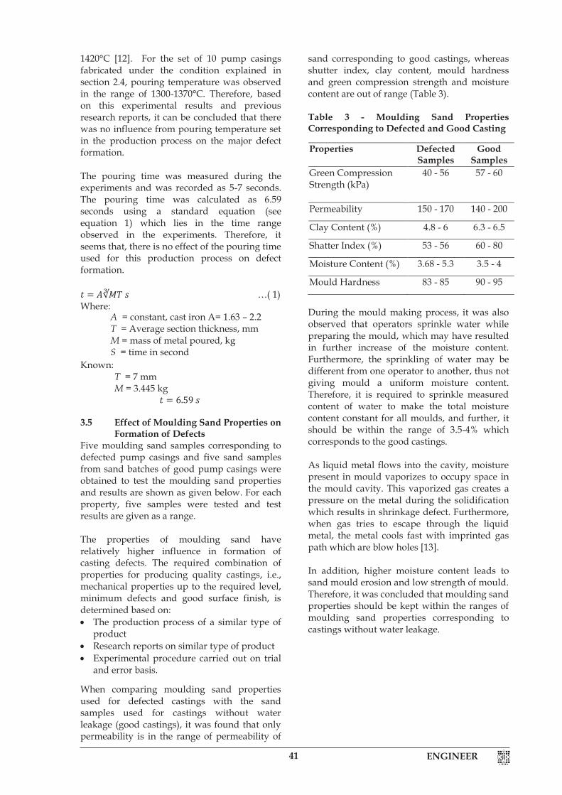
1420°C [12]. For the set of 10 pump casings fabricated under the condition explained in section 2.4, pouring temperature was observed in the range of 1300-1370°C. Therefore, based on this experimental results and previous research reports, it can be concluded that there was no influence from pouring temperature set in the production process on the major defect formation. The pouring time was measured during the experiments and was recorded as 5-7 seconds. The pouring time was calculated as 6.59 seconds using a standard equation (see equation 1) which lies in the time range observed in the experiments. Therefore, it seems that, there is no effect of the pouring time used for this production process on defect formation. 𝑡𝑡 = 𝐴𝐴∛𝑀𝑀𝑀𝑀 𝑠𝑠 …( 1) Where: Known: T = 7 mm M = 3.445 kg
𝑡𝑡 = 6.59 𝑠𝑠 3.5 Effect of Moulding Sand Properties on
Formation of Defects Five moulding sand samples corresponding to defected pump casings and five sand samples from sand batches of good pump casings were obtained to test the moulding sand properties and results are shown as given below. For each property, five samples were tested and test results are given as a range. The properties of moulding sand have relatively higher influence in formation of casting defects. The required combination of properties for producing quality castings, i.e., mechanical properties up to the required level, minimum defects and good surface finish, is determined based on: The production process of a similar type of
product Research reports on similar type of product Experimental procedure carried out on trial
and error basis.
When comparing moulding sand properties used for defected castings with the sand samples used for castings without water leakage (good castings), it was found that only permeability is in the range of permeability of
sand corresponding to good castings, whereas shutter index, clay content, mould hardness and green compression strength and moisture content are out of range (Table 3). Table 3 - Moulding Sand Properties Corresponding to Defected and Good Casting
During the mould making process, it was also observed that operators sprinkle water while preparing the mould, which may have resulted in further increase of the moisture content. Furthermore, the sprinkling of water may be different from one operator to another, thus not giving mould a uniform moisture content. Therefore, it is required to sprinkle measured content of water to make the total moisture content constant for all moulds, and further, it should be within the range of 3.5-4% which corresponds to the good castings. As liquid metal flows into the cavity, moisture present in mould vaporizes to occupy space in the mould cavity. This vaporized gas creates a pressure on the metal during the solidification which results in shrinkage defect. Furthermore, when gas tries to escape through the liquid metal, the metal cools fast with imprinted gas path which are blow holes [13]. In addition, higher moisture content leads to sand mould erosion and low strength of mould. Therefore, it was concluded that moulding sand properties should be kept within the ranges of moulding sand properties corresponding to castings without water leakage.
Properties Defected Samples
Good Samples
Green Compression Strength (kPa)
40 - 56 57 - 60
Permeability 150 - 170 140 - 200
Clay Content (%) 4.8 - 6 6.3 - 6.5
Shatter Index (%) 53 - 56 60 - 80
Moisture Content (%) 3.68 - 5.3 3.5 - 4
Mould Hardness 83 - 85 90 - 95

ENGINEER 42ENGINEER 6
3.6 Effect of Gating System on Formation of Defects
Gating system parameters which are generally affecting formation of defects of moulds corresponding to defected and good pump casing were measured (Table 4). These results showed that in both cases there is no significant difference between the gating system parameters.
Table 4 - Currently Used Gating System Dimensions for Both Good and Defective Casting
However, it was decided to recalculate/design all these parameters based on the standard AFS recommended formulas/equations and compare those with the existing values/designs.
Calculation of Gating system parameters based on AFS formulas/equations Sprue Designing The existing gating system has a straight side sprue. However, tapered sprue is generally recommended for this type of moulds since it prevents the entrance of air and decreases turbulence [14]. Thus, tapered sprue helps in reduction of blowhole and shrinkage. To calculate the dimension of the taper sprue, following calculations are carried out; I. Effective Height: H
𝐻𝐻 = ℎ − 𝑃𝑃2
2𝑐𝑐 …(2) Where; II. Choke Area
𝐴𝐴 = 𝑊𝑊𝑑𝑑𝑑𝑑𝑐𝑐√2𝑔𝑔𝑔𝑔 …(3)
Where; III. Pouring Basin Height,h1 (Figure 7)
ℎ1 = ℎ − 𝐻𝐻 …(4) Where; IV. Sprue Diameter, d1 (Figure 8)
𝑉𝑉12 − 𝑉𝑉0
2 = 2𝑔𝑔ℎ1 …(5) Where; According to volume flow rate: 𝑉𝑉1𝐴𝐴1 = 𝑉𝑉2𝐴𝐴2 …(6),
Known, 𝑉𝑉2, 𝐴𝐴2, 𝑉𝑉1, velocities and areas at the sprue and choke (see Figure 8)
𝐴𝐴1 = 334.67 mm2 𝐴𝐴1 = 𝜋𝜋
4 × 𝑑𝑑12 …(7)
Gating Part Dimensions Sprue Straight side sprue
with diameter of 18.75 mm
Ingate diameter 6.87 mm Runner length 30 – 40 mm Gating ratio 1:0.9:0.4
H = Effective height, mm h = Sprue height, mm c = height of the casting cavity, mm P = height of the cavity in the cope, mm
A = Chock area, mm2 c = Efficiency co-efficient for bottom
gating H = Effective height, mm d = Density of metal, kg/m3 w = mass of the pump casing, kg g = gravity acceleration = 9.81 m/s2 t = Metal pouring time, s
ℎ1 = Basin height, mm H = Effective height, mm h = Sprue height, mm
ℎ1 = Basin height, mm V = Velocity
Basin Height (h1)
Sprue Height (h)
Currently used Recommended Tapered Sprue
Figure 7 - Currently Used and Recommended Sprue Shape
Cope Cope
Drag Drag
Sprue Sprue
Runner Runner
Core Core
Sprue Well Sprue
Figure 6 - Sand Mould Used for the Manufacturing of Pump Casing

ENGINEER43ENGINEER 6
3.6 Effect of Gating System on Formation of Defects
Gating system parameters which are generally affecting formation of defects of moulds corresponding to defected and good pump casing were measured (Table 4). These results showed that in both cases there is no significant difference between the gating system parameters.
Table 4 - Currently Used Gating System Dimensions for Both Good and Defective Casting
However, it was decided to recalculate/design all these parameters based on the standard AFS recommended formulas/equations and compare those with the existing values/designs.
Calculation of Gating system parameters based on AFS formulas/equations Sprue Designing The existing gating system has a straight side sprue. However, tapered sprue is generally recommended for this type of moulds since it prevents the entrance of air and decreases turbulence [14]. Thus, tapered sprue helps in reduction of blowhole and shrinkage. To calculate the dimension of the taper sprue, following calculations are carried out; I. Effective Height: H
𝐻𝐻 = ℎ − 𝑃𝑃2
2𝑐𝑐 …(2) Where; II. Choke Area
𝐴𝐴 = 𝑊𝑊𝑑𝑑𝑑𝑑𝑐𝑐√2𝑔𝑔𝑔𝑔 …(3)
Where; III. Pouring Basin Height,h1 (Figure 7)
ℎ1 = ℎ − 𝐻𝐻 …(4) Where; IV. Sprue Diameter, d1 (Figure 8)
𝑉𝑉12 − 𝑉𝑉0
2 = 2𝑔𝑔ℎ1 …(5) Where; According to volume flow rate: 𝑉𝑉1𝐴𝐴1 = 𝑉𝑉2𝐴𝐴2 …(6),
Known, 𝑉𝑉2, 𝐴𝐴2, 𝑉𝑉1, velocities and areas at the sprue and choke (see Figure 8)
𝐴𝐴1 = 334.67 mm2 𝐴𝐴1 = 𝜋𝜋
4 × 𝑑𝑑12 …(7)
Gating Part Dimensions Sprue Straight side sprue
with diameter of 18.75 mm
Ingate diameter 6.87 mm Runner length 30 – 40 mm Gating ratio 1:0.9:0.4
H = Effective height, mm h = Sprue height, mm c = height of the casting cavity, mm P = height of the cavity in the cope, mm
A = Chock area, mm2 c = Efficiency co-efficient for bottom
gating H = Effective height, mm d = Density of metal, kg/m3 w = mass of the pump casing, kg g = gravity acceleration = 9.81 m/s2 t = Metal pouring time, s
ℎ1 = Basin height, mm H = Effective height, mm h = Sprue height, mm
ℎ1 = Basin height, mm V = Velocity
Basin Height (h1)
Sprue Height (h)
Currently used Recommended Tapered Sprue
Figure 7 - Currently Used and Recommended Sprue Shape
Cope Cope
Drag Drag
Sprue Sprue
Runner Runner
Core Core
Sprue Well Sprue
Figure 6 - Sand Mould Used for the Manufacturing of Pump Casing
7 ENGINEER
Therefore,
𝑑𝑑1 = √4𝐴𝐴1𝜋𝜋
V. Ingate Calculation Gating Ratio currently used in casting water pump casing = 𝐴𝐴𝑠𝑠: 𝐴𝐴𝑅𝑅: 𝐴𝐴𝑔𝑔 = 1:0.9:0.4 𝐴𝐴𝑠𝑠: 𝐴𝐴𝑅𝑅: 𝐴𝐴𝑔𝑔 = Total area of sprue: Total area of runner: Total area of ingate 𝐴𝐴𝑔𝑔 = 𝜋𝜋𝑟𝑟2 = 0.4 × 𝑐𝑐ℎ𝑜𝑜𝑜𝑜𝑜𝑜 𝑎𝑎𝑟𝑟𝑜𝑜𝑎𝑎 ...(8)
Where; Ag = total ingate area
The gating ratio currently used for manufacturing of pump casing is 1:0.9:0.4 which gives a single ingate diameter of 6.87 mm (Figure 9). This smaller diameter results in high pressure which creates turbulent flow. As a result of this, pressure and thermal stresses on the mould are increased [15]. Furthermore, turbulence may produce casting defects such as gas holes and blow holes due to entrapped gases in the flowing metal. These entrapped gases may lead to formation of dross or
inclusions by reacting with liquid metal [15], therefore, gating ratio of 1:0.9:0.7 is proposed which gives a relatively higher ingate diameter of 9.06 mm and which will reduce the creation of turbulent flow. In the current gating system, there is a significant difference in the runner length, Lr at all positions and it varies from 30 to 40 mm (Figure 10). However, it is recommended to set the runner length, Lr at least 50 mm and should be made uniform within a mould to regulate the speed of the molten metal that leads to avoid shrinkage and minimize the turbulence [16]. Table 5 - Comparison of Recommended Gating Dimensions and Existing Dimensions
Gating Part
Recommended Dimensions (mm)
Existing Dimension
Sprue
Tapered sprue with: top diameter, d1 = 20.73 mm, chock diameter, d2 = 15.35 mm Pouring basin height, h1 = 20.15 mm Effective height, H = 45.25 mm
Sprue diameter 18.75 mm
Ingate diameter
dr=9.08 mm
6.87 mm
Runner length
Lr=50 mm
30 – 40 mm
Gating ratio
1:0.9:0.7
1:0.9:0.4
Figure 9 - Ingate of the Gating System
Figure 8 - Taper Sprue Diameters
Diameter at sprue = 𝑑𝑑1 = 20.73 mm
Diameter at chock = 𝑑𝑑2 = 15.35 mm
Figure 10 - Runner Length of the Gating System
ENGINEER 44ENGINEER 8
4. Conclusions Quantitative and qualitative analysis of
defects showed shrinkages and blow holes with the defect percentage of 35% and 38% respectively, are the major defects which critically contribute to the water leakage.
Based on the experimental results, it was concluded that there is no effect of chemical composition of the scrap batches and metal pouring temperature on defect formation.
It was found that only permeability is in the range of permeability of sand corresponding to good castings, whereas shutter index, clay content, mold hardness and green compression strength and moisture content are in out of range. Therefore, it is required to develop the moulding sand preparation process to make it more homogeneous.
Even though good castings can be obtained by the present gating system due to the dominant effect of moulding sand properties within the required ranges in some moulds, it is recommended to modify the gating system by correcting the parameters as shown in Table 5.
Acknowledgement The authors would like to thank all members of the academic and non-academic staff of the Department of Materials Science and Engineering at the University of Moratuwa who assisted in this research. We would like to express our appreciation to Jinasena (Pvt) Ltd for their technical assistance and for providing material samples. We would also like to express our gratitude to Mr. A. Jayathilake, In-charge of NDT Inspection, Atomic Energy Board, for his assistance in conducting radiography testing.
References 1. De Silva, G. I. P & Munasinghe, N., “Quality
Enhancement of Foundry Products - A Case Study of Foundry Industry of Sri Lanka,” Institution of Engineers Sri Lanka (IESL), vol. XXXVIII, no. 01,I, pp. 46-56, 2005.
2. Chaudhari, S. & Thakkar, H. T, “Review on Analysis of Foundry Defects for Quality Improvement of Sand Casting,” Int. Journal of Engineering Research and Applications, vol. 4, no. 03(version 1), pp. 615-618, March 2014.
3. De Silva, G. I. P, “"Enhancement of Surface Quality of Brass Casting Cost Effectively Using Naturally Available Sand and Clay Available in Sri Lanka",” in M.Phil Dissertation:, University of Moratuwa, 2006, pp. 22-28.
4. Sheth, H., Shah, K., Sathwara, D. & Trivedi, R, “Investigation, Analysis of Casting Defect by Using Statistical Quality Control Tools,” International Journal for Engineering Development and Research (IJEDR), vol. 03, no. 4, pp. 47-254, 2015.
5. Ranasiri, K. M. & Muzathik, A. M., “Defects Analysis, Minimize Metal Wastages and Yield Improvement for Grey Cast Iron Casting: A Case Study,” Material Science, An Indian Journal (MSAIJ), vol. 11(6), pp. 218-224, 2014.
6. LLC, Inspection 4 Industry, “Inspection 4 Industry LLC,” 2012 - 2013. [Online]. Available: https://www.inspectionforindustry.com/pump-casing-hydrostatic-test.htlm. [Accessed 28 08 2019].
7. G. V. Voort, “Vac Aero internation inc.,” 10 6 2015. [Online]. Available: https://vacaero.com/information-resources/metallography-with-george-vander-voort/1444-metallographic-procedures-for-cast-iron.html. [Accessed 12 10 2019].
8. Kumar, N., Singh, A. K., Patel, S., Kumar, A. & Kumar, S., “Macroshrinkage and Mold Height Correlation for GreyCast Iron Casting,” International Journal of Computational Engineering Research (IJCER), vol. 04, no. 6, pp. 63-68, 2014.
9. Gonzalez, M., “Modelling the Microstructure and Mechanical Properties of Austempered Ductile Iron,” in Ph.D Dissertation, University of Cambridge, 2001, pp. 45-48.
10. Lobenhofer, R., “Tensile Properties,” 31 3 2015. [Online]. Available: http://www.lobenhofer .com/Tensile properties/effect_of_elements_in_gray.htm. [Accessed 04 04 2020].
11. Raji, A. and Khan, R. H, “Effects of Pouring Temperature and Squeeze Pressure on Al-8% Si Alloy Squeeze Cast Parts,” AU Journal of Technology, vol. 9, no. 4, pp. 229-237, 2006.
12. De Silva, G. I. P, “Foundry Industry in Sri Lanka,”, Institute of Engineer Sri Lanka (IESL), 2019, p. 50.
13. Shivappa, D. N. & Bhattacharya, A., “Analysis of Casting Defects and Identification of Remedial Measures - A Diagnostic Study,” International Journal of Engineering Inventions, vol. 1, no. 6, p. 125, 2012.

ENGINEER45
9 ENGINEER
14. Nandagopal, M., Sivakumar, K., Senthilkumar, G. & Sengottuvelan, M., “Study of Sand Casting Gating System,” International Journal of Recent Engineering Research and Development (IJRERD), vol. 2, no. 11, pp. 19-26, November, 2017.
15. Ahmad, R. & Hashim, M. Y., “Effect of Vortex Runner Gating System on Mechanical Strength of Al-12Si Alloy Casting,” Aechives of Metallurgy and Materials, vol. 56, no. 4, pp. 991-997, 2011.
16. Iqbal, M., “Gating Design Criteria for Sound Casting,” International Journal of Mechanical Engineering and Robotics Research, vol. 2, no. 3, pp. 675-694, July, 2014.