A Study of The Preload Performance of Subsea Wellhead ... · A Study of The Preload Performance of...
10
A Study of The Preload Performance of Subsea Wellhead Connector with a New Locking Mechanism *1 Wang Chuan, 1 Hongwu Zhu, 1 Kuang Ding, 1 Yinxun Zhang *1 College of Mechanical and Transportation Engineering, China University of Petroleum, Beijing, China [email protected] Abstract Subsea wellhead connector plays an important role in offshore drilling operation, it meets high reliability and safety requirement by guaranteeing the preload performance. In this paper, a new effective non-frictional locking mechanism was developed, and then a connector-wellhead system finite element model was built to analyze and compare the preload capacity of connector under two main load cases. Bolts and metal gasket were the confirmed governing components. Friction and tolerances were important factors that influent preload. The experimental setup including rig and measuring equipment was described. Tensile experiments with inner pressure were performed on the prototype of connector. The experiment results and finite element analysis showed a well agreement on locking pressure, hub face separation point and friction sensitivity, which validated availability and accuracy of analysis method, and provided technical supports for other types of subsea wellhead connector. Keywords: Subsea Wellhead Connector, Preload, Hub Face, Sensitivity 1. Introduction In offshore oil and gas exploration, subsea wellhead connector is used to attach upper stalk, such as subsea blowout preventer, subsea tree, to wellhead and energize a metal seal gasket [1]. The effective hub face preload of connector should be equal to or greater than the combined separation forces due to internal pressure, riser tension, and bending moments to ensure the integrity of the connection in normal operating conditions [2] [3]. Therefore, several studies have been performed to analyze and evaluate the preload performance of subsea wellhead connectors. But there are still issues in previous works: (1) the works mainly focused on the performance of locking and leak tightness, did not confirm the governing components and the relationship between relative parameters in different loading cases [4-7]; (2) the finite element model (FEM) was two-dimensional axisymmetric elements, which cannot precisely simulate the non-axisymmetric deformation and components, such as lock ring [8] [9]; (3) these works did not study the preload sensitivity to tolerance and friction. Moreover, the connector must maintain a positive effective preload to counteract the separation forces during the entire operation [10]. The conventional design method is to maintain locking pressure on a tapered locking mechanism throughout the working period [11]. This approach has two significant disadvantages. (1) As the connector is self-locked by friction, drilling vibrations, separation forces, and temperature fluctuations could cause a significant preload loss. (2) The friction of taper increases during lock/unlock cycles, which requires a rising unlocked releasing pressure. The first part of this paper presented a design of subsea wellhead connector with a new non- frictional locking mechanism. Then, a three-dimensional FEM of connector-wellhead system was built. The preload capacity of connector in different load cases was analyzed. The tolerance and friction sensitivity of preload were studied. Moreover, a full-scale tensile testing with internal pressure was performed on the prototype to validate the availability and accuracy of the finite element analysis (FEA) method. Although this work was specifically performed on the subsea wellhead connector with bolt connection, the method and results have wider implications on the analysis and design of other types of subsea wellhead connector. 2. Design Structure and Construction The hydraulically actuated wellhead connector provides pressure integrity and a rigid structural connection between the subsea BOP and the high-pressure wellhead with H4 profile. The major components of connector, shown in Figure 1, consists of the body spool, outer sleeve, lock piston, A Study of The Preload Performance of Subsea Wellhead Connector with a New Locking Mechanism Wang Chuan, Hongwu Zhu, Kuang Ding, Yinxun Zhang Journal of Convergence Information Technology(JCIT) Volume8, Number6,Mar 2013 doi:10.4156/jcit.vol8.issue6.81
Transcript of A Study of The Preload Performance of Subsea Wellhead ... · A Study of The Preload Performance of...

A Study of The Preload Performance of Subsea Wellhead Connector with a New Locking Mechanism
*1 Wang Chuan, 1 Hongwu Zhu, 1 Kuang Ding, 1 Yinxun Zhang
*1 College of Mechanical and Transportation Engineering, China University of Petroleum, Beijing, China [email protected]
Abstract
Subsea wellhead connector plays an important role in offshore drilling operation, it meets high reliability and safety requirement by guaranteeing the preload performance. In this paper, a new effective non-frictional locking mechanism was developed, and then a connector-wellhead system finite element model was built to analyze and compare the preload capacity of connector under two main load cases. Bolts and metal gasket were the confirmed governing components. Friction and tolerances were important factors that influent preload. The experimental setup including rig and measuring equipment was described. Tensile experiments with inner pressure were performed on the prototype of connector. The experiment results and finite element analysis showed a well agreement on locking pressure, hub face separation point and friction sensitivity, which validated availability and accuracy of analysis method, and provided technical supports for other types of subsea wellhead connector.
Keywords: Subsea Wellhead Connector, Preload, Hub Face, Sensitivity
1. Introduction
In offshore oil and gas exploration, subsea wellhead connector is used to attach upper stalk, such as
subsea blowout preventer, subsea tree, to wellhead and energize a metal seal gasket [1]. The effective hub face preload of connector should be equal to or greater than the combined separation forces due to internal pressure, riser tension, and bending moments to ensure the integrity of the connection in normal operating conditions [2] [3]. Therefore, several studies have been performed to analyze and evaluate the preload performance of subsea wellhead connectors. But there are still issues in previous works: (1) the works mainly focused on the performance of locking and leak tightness, did not confirm the governing components and the relationship between relative parameters in different loading cases [4-7]; (2) the finite element model (FEM) was two-dimensional axisymmetric elements, which cannot precisely simulate the non-axisymmetric deformation and components, such as lock ring [8] [9]; (3) these works did not study the preload sensitivity to tolerance and friction.
Moreover, the connector must maintain a positive effective preload to counteract the separation forces during the entire operation [10]. The conventional design method is to maintain locking pressure on a tapered locking mechanism throughout the working period [11]. This approach has two significant disadvantages. (1) As the connector is self-locked by friction, drilling vibrations, separation forces, and temperature fluctuations could cause a significant preload loss. (2) The friction of taper increases during lock/unlock cycles, which requires a rising unlocked releasing pressure.
The first part of this paper presented a design of subsea wellhead connector with a new non-frictional locking mechanism. Then, a three-dimensional FEM of connector-wellhead system was built. The preload capacity of connector in different load cases was analyzed. The tolerance and friction sensitivity of preload were studied. Moreover, a full-scale tensile testing with internal pressure was performed on the prototype to validate the availability and accuracy of the finite element analysis (FEA) method. Although this work was specifically performed on the subsea wellhead connector with bolt connection, the method and results have wider implications on the analysis and design of other types of subsea wellhead connector.
2. Design Structure and Construction
The hydraulically actuated wellhead connector provides pressure integrity and a rigid structural
connection between the subsea BOP and the high-pressure wellhead with H4 profile. The major components of connector, shown in Figure 1, consists of the body spool, outer sleeve, lock piston,
A Study of The Preload Performance of Subsea Wellhead Connector with a New Locking Mechanism Wang Chuan, Hongwu Zhu, Kuang Ding, Yinxun Zhang
Journal of Convergence Information Technology(JCIT) Volume8, Number6,Mar 2013 doi:10.4156/jcit.vol8.issue6.81

sliding lock sleeve, split lock ring and preloaded bolts keeping the lower body to the body spool. The connector is locked by applying hydraulic pressure in the space above the lock piston. This generates a downward locking force on the lock piston which is transferred to the lock sleeve. As the lock sleeve travels down, the lock ring is compressed radially. Then connector locks to the wellhead by means of a split lock ring with four teeth that engage matching grooves on the wellhead, which forces the lower body down and generates a stretch in the bolts. This stretch ultimately results in a compressive preload between the body spool and the wellhead. As Figure 2 shows, a new locking mechanism was developed. The surface between the lock sleeve and the lock ring has 5° preload contact tapers to generate preload and 0° self-lock tapers to lock the split lock ring in place. Unlike the use of a self-lock taper in the previous design, this new taper has no need to maintain hydraulic pressure on the lock piston and the preload is independent of the friction, as the connector has 0° angle self-lock tapers. The metal gasket is the primary method of sealing between wellhead and connector. During installation, the lock ring pulls down the connector. This action preloads the metal gasket between the top of the wellhead and the body spool, and then causes self-seating of gasket. When internal pressure is applied, the seal/seat is pressure energized. The self-seating and pressure-energized metal gasket must provide leak tightness even at some limited structural conditions. The separation load is defined as the external load which causes the contact force between the wellhead and the body spool, which is defined as hub face force, to be of zero magnitude.
Figure 1. Schematic illustration of the subsea wellhead connector
Figure 2. New locking mechanism and friction contact interfaces
3. Finite Element Modeling
A three-dimensional FEM of connector-wellhead system was developed using the ABAQUS
software. The geometric characteristics of connector are symmetrical about an axis. They can be
BodyspoolOutersleeveLockpiston
Metalgasket SlidelocksleeveSlidelockingring UnlockpistonBoltLowerbody
Wellhead
D
Nut
A Study of The Preload Performance of Subsea Wellhead Connector with a New Locking Mechanism Wang Chuan, Hongwu Zhu, Kuang Ding, Yinxun Zhang
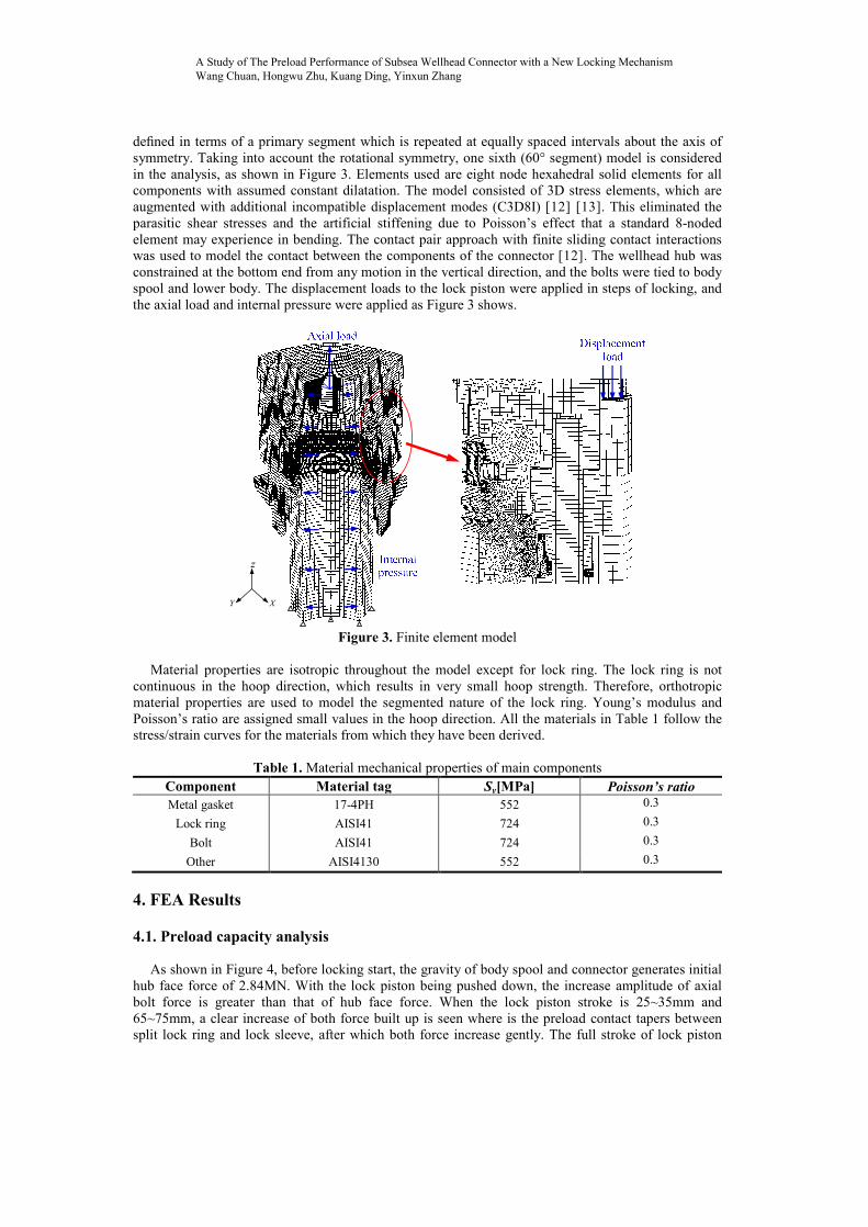
defined in terms of a primary segment which is repeated at equally spaced intervals about the axis of symmetry. Taking into account the rotational symmetry, one sixth (60° segment) model is considered in the analysis, as shown in Figure 3. Elements used are eight node hexahedral solid elements for all components with assumed constant dilatation. The model consisted of 3D stress elements, which are augmented with additional incompatible displacement modes (C3D8I) [12] [13]. This eliminated the parasitic shear stresses and the artificial stiffening due to Poisson’s effect that a standard 8-noded element may experience in bending. The contact pair approach with finite sliding contact interactions was used to model the contact between the components of the connector [12]. The wellhead hub was constrained at the bottom end from any motion in the vertical direction, and the bolts were tied to body spool and lower body. The displacement loads to the lock piston were applied in steps of locking, and the axial load and internal pressure were applied as Figure 3 shows.
z
Y X
Figure 3. Finite element model
Material properties are isotropic throughout the model except for lock ring. The lock ring is not
continuous in the hoop direction, which results in very small hoop strength. Therefore, orthotropic material properties are used to model the segmented nature of the lock ring. Young’s modulus and Poisson’s ratio are assigned small values in the hoop direction. All the materials in Table 1 follow the stress/strain curves for the materials from which they have been derived.
Table 1. Material mechanical properties of main components
Component Material tag Sy[MPa] Poisson’s ratio Metal gasket 17-4PH 552 0.3
Lock ring AISI41 724 0.3
Bolt AISI41 724 0.3
Other AISI4130 552 0.3
4. FEA Results 4.1. Preload capacity analysis
As shown in Figure 4, before locking start, the gravity of body spool and connector generates initial
hub face force of 2.84MN. With the lock piston being pushed down, the increase amplitude of axial bolt force is greater than that of hub face force. When the lock piston stroke is 25~35mm and 65~75mm, a clear increase of both force built up is seen where is the preload contact tapers between split lock ring and lock sleeve, after which both force increase gently. The full stroke of lock piston
A Study of The Preload Performance of Subsea Wellhead Connector with a New Locking Mechanism Wang Chuan, Hongwu Zhu, Kuang Ding, Yinxun Zhang
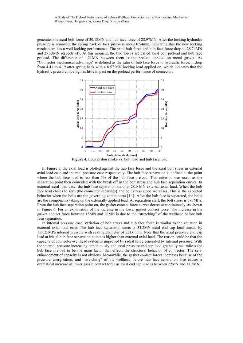
generates the axial bolt force of 30.18MN and hub face force of 28.97MN. After the locking hydraulic pressure is removed, the spring back of lock piston is about 0.54mm, indicating that the new locking mechanism has a well locking performance. The axial bolt force and hub face force drop to 28.74MN and 27.53MN respectively. At this moment, the two forces are called axial bolt preload and hub face preload. The difference of 1.21MN between them is the preload applied on metal gasket. As "Connector mechanical advantage" is defined as the ratio of hub face force to hydraulic force, it drop from 4.41 to 4.19 after spring back with a 6.57 MN locking load applied on, which indicates that the hydraulic pressure moving has little impact on the preload performance of connector.
0
5
10
15
20
25
30
35
0
5
10
15
20
25
30
35
0 10 20 30 40 50 60 70 80 90 100
Hub
fac
e fo
rce
[MN
]
Axi
al b
olt
forc
e [M
N]
Lock piston stroke [mm]
Axial bolt forceHub face force
Figure 4. Lock piston stroke vs. bolt load and hub face load
In Figure 5, the axial load is plotted against the hub face force and the axial bolt stress in external
axial load case and internal pressure case respectively. The hub face separation is defined at the point where the hub face load is less than 5% of the hub face preload. This criterion was used, as the separation point then coincided with the break off in the bolt stress and hub face separation curves. In external axial load case, the hub face separation starts at 28.0 MN external axial load. When the hub face load closes to zero (the connector separates), the bolt stress slope increases. This is the expected behavior when the bolts are the governing components [14]. After the hub face is separated, the bolts are the components taking up the externally applied load. At separation start, the bolt stress is 398MPa. From the hub face separation point on, the gasket contact force curves decrease continuously, as shown in Figure 6. For an explanation of the increase in the lower gasket contact force. The increase in the gasket contact force between 18MN and 26MN is due to the “stretching” of the wellhead before hub face separation.
In internal pressure case, variation of bolt stress and hub face force is similar to the situation in external axial load case. The hub face separation starts at 33.2MN axial end cap load caused by 155.25MPa internal pressure with sealing diameter of 521.6 mm. Note that the axial pressure end cap load at initial hub face separation points is higher than external axial load. The reason could be that the capacity of connector-wellhead system is improved by radial force generated by internal pressure. With the internal pressure increasing continuously, the axial pressure end cap load gradually neutralizes the hub face preload to be the main factor that effects the structural behavior of connector. The self-enhancement of capacity is not obvious. Meanwhile, the gasket contact forces increases because of the pressure energization, and “stretching” of the wellhead before hub face separation also causes a dramatical increase of lower gasket contact force as axial end cap load is between 22MN and 33.2MN.
A Study of The Preload Performance of Subsea Wellhead Connector with a New Locking Mechanism Wang Chuan, Hongwu Zhu, Kuang Ding, Yinxun Zhang

09182736
300400500600700
0 10 20 30 40 50
Hubfaceforce[MN]
Boltstress[M
Pa]
Externalaxial load[MN],Axialendcaploadcausedbyinternalpressure[MN]
Boltstress,axialforceBoltstress,internalpressureHubfaceforce,axialforceHubfaceforce,internalpressureStart ofhubfaceseparation inaxialforce case
Start ofhubfaceseparation ininternalpressure case
Figure 5. External axial load and end cap load vs. bolt stress and hub face force
02000400060008000
1000012000
0 10 20 30 40 50
Gasketcontactforce[N/m
m]
Externalaxial load[MN],Axialendcaploadcausedbyinternalpressure[MN]
Gasketupper,internalpressureGasketlower,internalpressureGasketupper,axialloadGasketlower,axialload
Figure 6. External axial load and end cap load vs. gasket contact force
4.2. Preload friction sensitivity
The lock force is affected by variations in friction between sliding surfaces of locking mechanism. The three main sliding contact surfaces α, β, γ (with friction coefficient of υ1, υ2 and υ3 respectively, as Figure 2 shows) have different effect on the mechanical advantage. Figure 7 plots the relationship between mechanical advantage and friction coefficient when υ1=υ2=0, υ1=υ3=0, υ2=υ3=0 and υ1=υ2=υ3=υ to show on which surface friction might be most critical. Friction on α most heavily effects connector locking efficiency, and influence degree of υ1 is almost twice as υ2 and υ3. In υ1=υ2=υ3=υ case, connector mechanical advantage dramatically decrease 61.4% as friction coefficient increases from υ= 0 to υ= 0.1, and then decrease to 0.86 gently as friction coefficient increases to 0.5. Engineering handbooks place sliding friction coefficients for clean, well finished, ideally lubricated, hard steel sliding on steel as low as about 0.03. For the same steel dry, the coefficient is about 0.4 [15]. Therefore, lubrication on contact surfaces and hardening of relevant components should be available methods to handle the friction [16]. In this work, a friction coefficient of 0.1 has been used between all sliding surfaces in all models for conservative consideration.
A Study of The Preload Performance of Subsea Wellhead Connector with a New Locking Mechanism Wang Chuan, Hongwu Zhu, Kuang Ding, Yinxun Zhang

0
1
2
3
4
5
6
7
8
9
10
11
12
0 0.05 0.1 0.15 0.2 0.25 0.3 0.35 0.4 0.45 0.5
Mec
hani
cal a
dvan
gtag
e
Friction coefficient(υ1, υ2, υ3)
υ1,υ2=υ3=0υ2,υ1=υ3=0υ3,υ1=υ2=0υ1=υ2=υ3=υ
Figure 7. Friction coefficient vs. mechanical advantage
4.3. Preload tolerance sensitivity
2530354045
2530354045
904904.5905905.5906906.5907
Hubfacepreloadforce[MN]
Hubfaceseparationforce[MN]
D[mm]
HubfacepreloadHubfaceseparation
Figure 8. Friction coefficient vs. mechanical advantage
Another factor affects the amount of preload is tolerance [17], including the tolerances on the
contacting surfaces, vertical position of the split lock ring and position of the contacting surfaces on the body spool and the wellhead. These tolerances can be changed by adjusting the position of the nuts during assembly to find the desired preload. Moving the nuts further up on the bolts increases the preload and vice versa. In order to check the change in hub face preload due to change in preload distances. The FEA was run several times, each time with a different distance D (see Figure 8). The maximum distance or base case has been used for all other FEA. The distance is reduced by 0.5 mm for each case. The preload and separation force of hub face raises 42% and 45% respectively, as D is reduced from 907mm to 904mm. The hub face separation force is slightly higher than hub face preload.
A Study of The Preload Performance of Subsea Wellhead Connector with a New Locking Mechanism Wang Chuan, Hongwu Zhu, Kuang Ding, Yinxun Zhang

5. Experiments
Figure 9. Schematic illustration of the connector experiment system
In order to validate the FEA, the full-scale experiments a prototype of connector were performed.
The experimental system, schematically shown in Figure 9, includes frame, assembly stump, four pistons, pumps, pressure sensors, data acquisition system, etc. The connector was loosely landed on the assembly stump and the lower body was pushed up into firm contact with the lock ring, then internal cavity was filled with water to simulate the internal pressure. After that, four hydraulic driven pistons applied external axial tension load on the top of upper body. The data acquisition system monitored the water pressure and hydraulic pressure through the pressure sensors on hydraulic and water lines. Axial strain gages on the outer diameter of bolts were used to monitor the tensile strains.
05
10152025303540
0 10 20 30 40 50 60 70 80 90 100
Lockpressure[MPa]
Lockpistontroke[mm]
TestFEA
Figure 10. Experimental data and FEA lock piston stroke vs. locking pressure
The FEA results from 3D model with base case preload are compared with test results in Figure 10.
The locking pressure of FEA was calculated using the reaction loads at the top of the lock piston. The lock piston stroke was collected using the mean value of the vertical displacements on the top of the lock piston. The maximum locking pressure from testing of 32MPa compares well with FEA results of
A Study of The Preload Performance of Subsea Wellhead Connector with a New Locking Mechanism Wang Chuan, Hongwu Zhu, Kuang Ding, Yinxun Zhang

34MPa. It should be noted that the FEA was analyzed with given displacement of the lock piston, hence, reduced load was observed after passing the radius on the lock ring. As experiment was performed with pressure control, any possible reduction in pressure is difficult to record.
250300350400450500550600650
0 5 10 15 20 25 30 35 40 45
Boltstress[M
Pa]
Totalaxialload[MN]
FEA-BoltstressTest-Boltstress
Figure 11. Experimental data and FEA bolt stress and hub face separation vs. external load
The experiment was performed with water at 5.2MPa pressure without leakage. The FEA results
and test data agree well for bolt stress and hub face behavior when subjected to axial tension, where total axial load equals to external applied tension plus the end cap load as shown in Figure 11. The differences of 6.2% in total axial load at the hub face separation point between the experimental results and the FEA results, respectively. The experimental results indicate a 29.2MN hub face separation tension capacity. Based on uncertainties in FEA analysis and measurements during testing in addition to possible reduction due to cyclic lock/unlock, the hub face tension capacity is kept at about 28MN.
02468
0.05 0.1 0.15 0.2 0.25
Mechanicaladvantage
Friction coefficient(υ1=υ2=υ3=υ)
FEATestInitial(0.07,5.4)50cycles(0.13,3.55)
100cycles(0.21,2.23)
Figure 12. Experimental data and FEA friction coefficient vs. mechanical advantage
The results of mechanical advantage in 100 lock/unlock cycles for the connector are shown in
Figure 12. Assumed that three main sliding contact surfaces have same friction coefficient (υ1=υ2=υ3=υ). The initial friction coefficient read from the curve is 0.07 with a 5.4 mechanical advantage. After 50 cycles, this connector lubricated can generate only about 65% of the hub face force it could initially. After about 100 cycles, this value drops to about 40%, corresponding to a mechanical
A Study of The Preload Performance of Subsea Wellhead Connector with a New Locking Mechanism Wang Chuan, Hongwu Zhu, Kuang Ding, Yinxun Zhang
advantage of 2.23. Note that the experiments were performed under ideally clean laboratory conditions, and the dropping situation of mechanical advantage will get worse in factory or operation condition.
6. Conclusion
A new non-frictional locking mechanism has been designed for subsea wellhead connector. A three-
dimensional connector-wellhead system model was developed to determine the preload performance of connector. From the FEA results, it was determined that the new locking mechanism shows a well locking performance because of the very small spring back of lock piston. After hub face separation start, the bolts are the main components taking up the externally applied load, and metal gasket should ensure an effective leakage tightness. The connector mechanical advantage has high sensitivity to the friction coefficient between slide contact surfaces, especially to the surface between lock sleeve and lock ring. Results from full-scale experiments show a reasonable agreement with the FEA results and indicate that the impact of cyclic lock/unlock on friction should be noted. To handle the friction, hardening of relevant components and lubrication on contact surfaces could be available.
7. Acknowledgements
National High-Technology Research and Development Program of China (No. 2012AA09A204)
8. References
[1] Yong Bai, Qiang Bai, Subsea engineering handbook, Elsevier Science Ltd, Netherland, 2012. [2] Thomas Kelly, Richard Strauss, “Agbami Field Development; Subsea Equipment Systems, Trees,
Manifolds and Controls”, In Proceeding(s) of Offshore Technology Conference, OTC19919, 2009. [3] Steve Lonnes, et al, “Successful Subsea Interventions in North Sea Beryl Field”, In Proceeding(s)
of SPE Annual Technical Conference and Exhibition, SPE 125258, 2009. [4] J.H. Owens III, “Seal Integrity and Connector Clamping Force at the Subsea Wellhead, In
Proceeding(s) of Offshore Technology Conference”, OTC 4483, 1983. [5] G.L. Glidden, S.P. Singeetham, “Improved Wellhead Connector Design-Preload Production and
Maintenance”, In Proceeding(s) of Offshore Technology Conference, OTC 4789, 1984. [6] T. Sweeney, K. Schnakenburg, “Behavior of 15-ksi Subsea Wellhead Gaskets as Determined by
Analysis and Testing”, In Proceeding(s) of Offshore Technology Conference, OTC 6708, 1991. [7] Robert Mack, Steve Norton, “Brittle Fracture of the Upper Tree Connector at Mensa - An
Analysis”, In Proceeding(s) of CORROSION 2001, NACE 01015, 2001. [8] S.l. Kandoker and P.D. Bunch, “Structural Analysis of 18¾-in. Drilling Connector”, In
Proceeding(s) of Offshore Technology Conference, OTC 6890, 1992. [9] Jacqueline Hsu, “Deepwater High-Capacity Collet Connector”, In Proceeding(s) of Offshore
Technology Conference, OTC 10968, 1999. [10] Petroleum and natural gas industries – Design and operation of subsea production systems – Part
7: Completion/workover riser systems. International Organization for Standardization. Switzerland, ISO/DIS 13628-7, 2010.
[11] Jaime Buitrago, Venkat Krishnan, and Paul Sommerfield, “Fatigue Assessment of Subsea Tree Connectors and Wellheads”, In Proceeding(s) of ASME 2011 30th International Conference on Ocean, Offshore and Arctic Engineering, pp. 423-432. 2012
[12] Abaqus Analysis User’s Manual, Dassault Systèmes, 2011. [13] Hu Sun, et al, “The Typical N-DOF Space Manipulator Modeling and Optimization”, AISS,
AICIT, Vol. 4, No. 19, pp. 429 ~ 437, 2012. [14] Kun Shi, et al, "Study of Structure with Joints based on Interface Stress Element Method", IJACT,
AICIT, Vol. 4, No. 16, pp. 404 ~ 411, 2012. [15] Eugene Avallone, Theodore Baumeister, and Ali Sadegh, Marks' Standard Handbook for
Mechanical Engineers 11th Edition, McGraw-Hill Companies, 2006. [16] Shu Xu, “Numerical Analysis of Manufacturing Process of New Desalination Unit”, IJACT,
AICIT, Vol. 4, No. 13, pp. 35 ~ 42, 2012.
A Study of The Preload Performance of Subsea Wellhead Connector with a New Locking Mechanism Wang Chuan, Hongwu Zhu, Kuang Ding, Yinxun Zhang

[17] Wei Wei, Guo Chen, and Duan Xiao-dong, "Tolerance Constraint-based Assembly Method in Virtual Assembly", AISS, AICIT, Vol. 4, No. 22, pp. 649 ~ 657, 2012
A Study of The Preload Performance of Subsea Wellhead Connector with a New Locking Mechanism Wang Chuan, Hongwu Zhu, Kuang Ding, Yinxun Zhang