A study of forward error correction for mobile multicast · the optimal FEC code dimensioning...
21
INTERNATIONAL JOURNAL OF COMMUNICATION SYSTEMS Int. J. Commun. Syst. 2011; 24:607–627 Published online 28 August 2010 in Wiley Online Library (wileyonlinelibrary.com). DOI: 10.1002/dac.1178 A study of forward error correction for mobile multicast Antonios Alexiou 1 , Christos Bouras 1,2, ∗, † and Andreas Papazois 1,2 1 Computer Engineering and Informatics Department, University of Patras, GR-26504 Patras, Greece 2 Research Academic Computer Technology Institute, N. Kazantzaki, GR-26504 Patras, Greece SUMMARY 3rd Generation Partnership Project (3GPP) has standardized the use of forward error correction (FEC) for the provision of reliable data transmission in the mobile multicast framework. This error control method inevitably adds a constant overhead in the transmitted data. However, it is so simple as to meet a prime objective for mobile multicast services; that is scalability to applications with thousands of receivers. In this paper, we present a study on the impact of application layer FEC on mobile multicast transmissions. We examine whether it is beneficial or not, how the optimal code dimension varies based on network conditions, which parameters affect the optimal code selection, and how this can be done. Additionally, we focus on one of the most critical aspects in mobile multicast transmission, which is power control. The evaluation is performed with the aid of a novel scheme that incorporates the properties of an evolved mobile network, as they are specified by the 3GPP. Copyright 2010 John Wiley & Sons, Ltd. Received 29 December 2009; Revised 6 May 2010; Accepted 6 July 2010 KEY WORDS: mobile networks; multicast; forward error correction; power control 1. INTRODUCTION There are many ways to provide reliability in multicast transmission. The best-known method that works efficiently for unicast transmission is the Automatic Repeat re-Quest (ARQ). When ARQ is applied in a multicast session, receivers send requests for retransmission of lost packets over a back channel towards the sender. Although ARQ is an effective and reliable tool for point-to- multipoint transmission, when the number of receivers increases, it reveals its limitations. One major limitation is the feedback implosion problem which occurs when too many receivers are transmitting back to the sender. A second problem of ARQ is that for a given packet loss rate, and a set of receivers experiencing losses, the probability that every single data packet needs to be retransmitted quickly approaches unity as the number of receivers increases. In other words, a high average number of transmissions are needed per packet. In wireless environments, ARQ has another major disadvantage. On most wired networks the feedback channel comes for free, but on wireless networks, the transmission of feedback from the receiver can be expensive, either in terms of power consumption, or due to limitations of the communication infrastructure. Thus, due to its requirement for a bidirectional communication link, the application of ARQ over wireless networks may be too costly or, in some cases, not possible. Forward error correction (FEC) is an error control method that can be used to augment or replace other methods for reliable data transmission. The main attribute of FEC schemes is that the sender adds redundant information in the messages transmitted to the receiver. This additional ∗ Correspondence to: Christos Bouras, Research Academic Computer Technology Institute, N. Kazantzaki, GR-26504 Patras, Greece. † E-mail: [email protected] Copyright 2010 John Wiley & Sons, Ltd.
Transcript of A study of forward error correction for mobile multicast · the optimal FEC code dimensioning...
INTERNATIONAL JOURNAL OF COMMUNICATION SYSTEMSInt. J. Commun. Syst. 2011; 24:607–627Published online 28 August 2010 in Wiley Online Library (wileyonlinelibrary.com). DOI: 10.1002/dac.1178
A study of forward error correction for mobile multicast
Antonios Alexiou1, Christos Bouras1,2,∗,† and Andreas Papazois1,2
1Computer Engineering and Informatics Department, University of Patras, GR-26504 Patras, Greece2Research Academic Computer Technology Institute, N. Kazantzaki, GR-26504 Patras, Greece
SUMMARY
3rd Generation Partnership Project (3GPP) has standardized the use of forward error correction (FEC) forthe provision of reliable data transmission in the mobile multicast framework. This error control methodinevitably adds a constant overhead in the transmitted data. However, it is so simple as to meet a primeobjective for mobile multicast services; that is scalability to applications with thousands of receivers.In this paper, we present a study on the impact of application layer FEC on mobile multicast transmissions.We examine whether it is beneficial or not, how the optimal code dimension varies based on networkconditions, which parameters affect the optimal code selection, and how this can be done. Additionally,we focus on one of the most critical aspects in mobile multicast transmission, which is power control.The evaluation is performed with the aid of a novel scheme that incorporates the properties of an evolvedmobile network, as they are specified by the 3GPP. Copyright � 2010 John Wiley & Sons, Ltd.
Received 29 December 2009; Revised 6 May 2010; Accepted 6 July 2010
KEY WORDS: mobile networks; multicast; forward error correction; power control
1. INTRODUCTION
There are many ways to provide reliability in multicast transmission. The best-known method thatworks efficiently for unicast transmission is the Automatic Repeat re-Quest (ARQ). When ARQis applied in a multicast session, receivers send requests for retransmission of lost packets overa back channel towards the sender. Although ARQ is an effective and reliable tool for point-to-multipoint transmission, when the number of receivers increases, it reveals its limitations. Onemajor limitation is the feedback implosion problem which occurs when too many receivers aretransmitting back to the sender. A second problem of ARQ is that for a given packet loss rate,and a set of receivers experiencing losses, the probability that every single data packet needs tobe retransmitted quickly approaches unity as the number of receivers increases. In other words, ahigh average number of transmissions are needed per packet. In wireless environments, ARQ hasanother major disadvantage. On most wired networks the feedback channel comes for free, buton wireless networks, the transmission of feedback from the receiver can be expensive, either interms of power consumption, or due to limitations of the communication infrastructure. Thus, dueto its requirement for a bidirectional communication link, the application of ARQ over wirelessnetworks may be too costly or, in some cases, not possible.
Forward error correction (FEC) is an error control method that can be used to augment orreplace other methods for reliable data transmission. The main attribute of FEC schemes is thatthe sender adds redundant information in the messages transmitted to the receiver. This additional
∗Correspondence to: Christos Bouras, Research Academic Computer Technology Institute, N. Kazantzaki, GR-26504Patras, Greece.
†E-mail: [email protected]
Copyright � 2010 John Wiley & Sons, Ltd.
608 A. ALEXIOU, C. BOURAS AND A. PAPAZOIS
data allow the receiver to reconstruct the source information. Such schemes inevitably add aconstant overhead in the transmitted data and are computationally expensive. In multicast proto-cols, however, the use of FEC techniques has very strong motivation. The encoding eliminatesthe effect of independent losses at different receivers. Additionally, the dramatic reduction in thepacket loss rate reduces the need to send feedback to the sender. Therefore, a feedback channelmay not be necessary or whenever feedback is required, the feedback implosion is avoided. FECschemes are therefore so simple as to meet a prime objective for mobile multicast services,which is scalability to applications with thousands of receivers. This is the reason why 3rdGeneration Partnership Project (3GPP) recommends the use of application layer FEC for Multi-media Broadcast/Multicast Service (MBMS) and, more specifically, adopts the use of RaptorFEC code [1].
In this paper, we study the applicability of FEC over the multicast data transmission in mobilenetworks. Our investigation is performed with the aid of a scheme that uses a probabilistic methodfor modeling the multicast user distribution in the network and estimates the telecommunicationcost of multicast data delivery. By using this model, we investigate the impact of FEC use inMBMS. We try to determine the efficient working point in the trade-off between the FEC codeoverhead and the retransmission cost. We also examine whether FEC use is beneficial or not, howthe optimal FEC code dimensioning varies based on the network conditions, which parametersaffect the optimal FEC code selection and how this can be done. Additionally, we focus on oneof the most critical aspects in mobile multicast transmission, which is the power control in theRadio Access Network (RAN). Our scheme incorporates the properties of an evolved mobilenetwork that uses High-Speed Downlink Packet Access (HSDPA) technology for high speed datadelivery to mobile terminals. Our assessment is not only from power consumption point of viewbut also from energy consumption and time perspective. It is important to mention that our analysisis in accordance with the 3GPP specifications and considers all the possible transport channelsdeployments in the RAN (point-to-point channels (p-t-p), the point-to-multipoint channels (p-t-m),and combinations of p-t-p and p-t-m transport channels). The outcome of our work is an extensiveinsight into all the aspects of the FEC application during mobile multicast transmission, some ofwhich have not been considered so far.
This paper is structured as follows: in Section 2 we present the work related to this scientificdomain. In Section 3 we provide an overview of MBMS and describe the key concepts that our studydeals with; namely, the power control in RAN and the FEC process in MBMS. Section 4 gives aninsight into the probabilistic method through which we model the multicast user distribution in themobile network. Section 5 provides a detailed description of our simulation scheme. In Section 6our simulation experiments and their results are thoroughly presented. Finally, some concludingremarks and possible next steps are stated in Sections 7 and 8 respectively.
2. RELATED WORK
The initial research on the use of FEC for multicasting was conducted in the domain of fixednetworks. The deployment of IP multicast in the Internet Multicast Backbone made the implemen-tation of error control functions more challenging for multicast than for unicast. As a result, a lot ofstudies have been published since then. A very representative study over this domain is describedin [2], where the authors propose a layered FEC scheme for video multicast over fixed networks.This scheme dictates that receivers can obtain different levels of protection that are commensuratewith their respective channel conditions. This is achieved through the organization of FEC intomultiple layers. The effects of bursty losses are amortized by staggering the FEC streams in time,giving rise to a trade-off between delay and quality.
The standardization of MBMS by 3GPP triggered the research on the use of FEC for multi-casting in the domain of mobile networks. Although this research area is relatively new, a lot ofsolutions have been proposed so far. In [3], an introduction in the Raptor code structure is presented.The Raptor codes are described through simple linear algebra notation. Several guidelines for the
Copyright � 2010 John Wiley & Sons, Ltd. Int. J. Commun. Syst. 2011; 24:607–627DOI: 10.1002/dac

A STUDY OF FEC FOR MOBILE MULTICAST 609
practical implementation of the relevant encoders and decoders are presented and the good perfor-mance of file broadcasting with Raptor codes is verified. The same study includes an investigationover the efficient implementation of Raptor codes in traditional broadcast systems like DigitalVideo Broadcast (DVB).
The study presented in [4] focuses on the determination of the MBMS Systematic FEC featuresand characteristics in order to deploy an optimum service from the operator’s point of view. Theperformance of Systematic Raptor FEC is evaluated through simulation experiments and detailedresults are presented. The experimental results are analyzed and the amount of additional FECrepair data is estimated for various packet error rates. The final conclusion is that although Raptorcoding adds redundant packets, it significantly improves the MBMS performance by recoveringthe lost packets during the transmission. Therefore, the deployment of Raptor codes would enablethe operator to reduce the allocated base station transmission power for MBMS service, and as aresult to improve the MBMS quality and extend the MBMS coverage.
The authors of [5] investigate the application of Raptor codes to MBMS in a realistic simu-lation environment. This work focuses on the download delivery method of MBMS and uses anoverall system model that represents accurately not only the application layer but also the phys-ical channel and the user mobility in a mobile network. In this realistic simulation environment,optimal system parameters are proposed for both application and physical layers under differentmobility models, with different bearer parameters. The achieved cross-layer optimization useslow transmission power and a modest amount of Turbo FEC coding in the physical layer, whichresults in relatively large radio packet loss rates and that is compensated for with a substantialamount of Raptor coding. Finally, it is concluded that these optimal operating points use farless transmission energy for download delivery of files than possible operating points withoutRaptor.
The study presented in [6] focuses on the MBMS download delivery method and deal withthe trade-off between the FEC protection and the successive file repair procedure. The authorspropose a novel file repair scheme that combines a p-t-m file repair transmission and a p-t-p filerepair procedure in a way that the UMTS resource usage is optimized. The proposed schemeaims at balancing the FEC transmission overhead with the file repair procedures after the MBMStransmission. It is concluded that using only a p-t-m file repair scheme is not efficient, since thesender does not know the amount of needed repair data. Additionally, the simulation results andtheir analysis show that the new scheme achieves better performance than a p-t-p-only file repairprocedure.
The adoption of FEC is examined from another aspect in [7]. A potential bottleneck of theradio network is taken into consideration and the authors investigate which are the optimaloperation points in order to save radio resources and use the available spectrum more effi-ciently. The conducted simulation experiments and the corresponding numerical results demon-strate the performance gain that Raptor code FEC offers in MBMS coverage. In more detail,the spectrum efficiency is significantly improved and resource savings are achieved in the radionetwork.
Despite the high quality and the scientific vigor of the published studies, none of these presentsa complete evaluation study of the use of FEC in mobile multicast. It is also important to mentionthat all the existing studies have focused on the legacy UMTS system and the application of FEChas not been presented in a framework that incorporates the evolution of UMTS beyond its 3rdgeneration. The goal achieved by our work is threefold. At a first level, we present an extensiveanalysis of FEC use in MBMS. In particular, the trade-off between the FEC overhead and theretransmission cost is examined under various user distributions and error rates. At a second level,our analysis covers the impact of FEC on base stations’ transmission power. Power control isone of the most important aspects in MBMS because Node B’s transmission power is a limitedresource and must be shared among all MBMS users in a cell. This in turn means that FEC powerefficiency is something that needs to be taken into account by the Radio Resource Management(RRM) mechanisms of next generation mobile networks. To our knowledge this aspect is notpresented so far by other research groups. At a third level, the advantages and drawbacks of FEC
Copyright � 2010 John Wiley & Sons, Ltd. Int. J. Commun. Syst. 2011; 24:607–627DOI: 10.1002/dac

610 A. ALEXIOU, C. BOURAS AND A. PAPAZOIS
use in HSDPA are highlighted. To that end, we believe that our work covers the issue of FECuse in MBMS transmissions with a comprehensive way and this is actually the motivation behindour study.
3. MBMS
3.1. Overview
MBMS is a p-t-m service in which data are transmitted from a single source entity to multiplerecipients. It provides the end user with two MBMS User Services; streaming delivery for real-timemultimedia streams and download delivery for reliable multicasting of files. 3GPP has specifiedthat these MBMS delivery methods make use of MBMS bearers for content delivery but may alsouse the associated delivery procedures for quality reporting and file repair. Streaming data suchas video streams, audio programs, or timed text being encapsulated in RTP are transported overthe streaming delivery network. On the other hand, during download delivery, discrete objectssuch as still images, text, multimedia data encapsulated in 3GPP file formats, or other binary dataare transported using the File Delivery over Unidirectional Transport (FLUTE) protocol whendelivering content over MBMS bearers [1]. Figure 1 gives an overview of the mobile networkentities and architecture as defined for MBMS by 3GPP [1].
Some basic mobile network nomenclature that is used in this paper is listed in Table I. Sincethis is not the purposes of this paper, the functionality of each element is not described. However,for more information on this, the reader is referred to the relevant bibliography, e.g. [8].
Figure 1. MBMS network architecture.
Copyright � 2010 John Wiley & Sons, Ltd. Int. J. Commun. Syst. 2011; 24:607–627DOI: 10.1002/dac

A STUDY OF FEC FOR MOBILE MULTICAST 611
Table I. Basic mobile networks nomenclature.
Acronym Expanded meaning
BM-SC Broadcast Multicast-Service CenterCN Core NetworkGGSN Gateway GPRS Support NodePDN Packet Data NetworkPLMN Public Land Mobile NetworkRA Routing AreaRNC Radio Network ControllerSGSN Serving GPRS Support NodeUE User EquipmentRRA RAN Registration AreaRAN Radio Access Network
Power control in the RAN is one of the most critical aspects in MBMS. The downlink transmis-sion power in mobile networks is the scarcest resource and, thus, it should be optimally utilized.The main purpose of power control is to minimize the transmitted power, thus avoiding unnecessaryhigh power levels and eliminating inter-cell interference. 3GPP specifies that MBMS data deliverycan be provided by either multiple p-t-p channels or by a single p-t-m channel. The most importanttypes of downlink transport channels are the High Speed-Downlink Shared Channel (HS-DSCH)and the Forward Access Channel (FACH). The HS-DSCH has been introduced for HSDPA oper-ation and is a p-t-p transport channel shared by several UEs. The FACH is a p-t-m channel and,consequently, a single FACH can carry information for more than one UE in a cell due to itsbroadcast nature [9].
During the p-t-p downlink transmissions through HS-DSCH, Link Adaptation functionality isused to maintain the quality of the link and thus to provide a reliable connection for the receiverto obtain the data with an acceptable error rate. Transmitting with just enough power to maintainthe required quality for the link also ensures that there is minimum interference affecting theneighboring cells. However, when a user consumes a high portion of power, more than actually isrequired, the remaining power, allocated for the rest of the users, is dramatically decreased, thusleading to a significant capacity loss in the system [8, 10].
During p-t-m downlink transmissions through FACH, base station transmits at a power levelthat is high enough to support the connection to the receiver with the highest power requirementamong all receivers in the multicast group. This would still be efficient because the receiver withthe highest power requirement would still need the same amount of power in a unicast link, andby satisfying that particular receiver’s requirement, the transmission power will be enough forall the other receivers in the multicast group. Consequently, the transmitted power is kept at arelatively high level in most of the time, which in turn, increases the signal quality at each receiverin the multicast group. On the other hand, a significant amount of power is wasted and moreoverinter-cell interference is increased [8, 10].
As a consequence, downlink transmission power has a key role in MBMS planning andoptimization. The coexistence of transport channels of different nature (both p-t-p and p-tm)in the same service and the capability of switching between these different types are someof the most important features of MBMS. Their importance is based on that these featuresallow high flexibility and a very efficient use of the scarce radio resources while the serviceconstraints are preserved [8–10]. The following paragraphs provide an analytical description of theHS-DSCH and FACH power profiles and their power consumption characteristics during MBMStransmissions.
3.2. HS-DSCH power profile
HS-DSCH is a rate controlled rather than a power controlled transport channel. In HSDPA,the fast power control characterizing Release ’99 channels is replaced by the Link Adaptationfunctionality, including techniques such as dynamic Adaptive Modulation and Coding (AMC),
Copyright � 2010 John Wiley & Sons, Ltd. Int. J. Commun. Syst. 2011; 24:607–627DOI: 10.1002/dac

612 A. ALEXIOU, C. BOURAS AND A. PAPAZOIS
multi-code operation, fast scheduling, Hybrid ARQ (HARQ), and short Transmission Time Interval(TTI) of 2 ms [8, 11].
The HS-DSCH Signal-to-Interference-plus-Noise Ratio (SINR) constitutes a new evaluationmetric that slightly differentiates HSDPA from that traditionally used in Release ’99 bearers.Release ‘99 typically uses Eb/N0 (received-energy-per-bit-to-noise ratio) that corresponds uniquelyto a certain Block Error Rate (BLER) for a given data rate. Eb/N0 metric is not an attrac-tive measure for HSDPA because the bit rate on the HS-DSCH is varied every TTI usingdifferent modulation schemes, effective code rates, and a number of High Speed-Physical DownlinkShared Channel (HS-PDSCH) codes. SINR for a single-antenna Rake receiver is calculated as inEquation (1) [8]:
SINR=SF16PHS-DSCH
(1−OF) · Pown + Pother+ Pnoise(1)
PHS-DSCH is the HS-DSCH transmission power, Pown is the own cell interference experiencedby the mobile user, Pother the interference from neighboring cells, and Pnoise the Additive WhiteGaussian Noise. Parameter OF is the downlink orthogonality factor. HSDPA modulation schemeemploys orthogonal codes in the downlink to separate users, and without any multipath propagationthe orthogonality remains when the base station signal is received by the mobile. However, if thereis sufficient delay spread in the radio channel, the mobile will see part of the base station signalas multiple access interference. The orthogonality of 1 corresponds to perfectly orthogonal users.Typically, the orthogonality is between 0.4 and 0.9 in multipath channels. On the other hand, SF16is the spreading factor of 16. The spreading factor or processing gain is the ratio of the chip ratedivided by the symbol rate. For more information on the concepts of OF and SF16, the reader isreferred to [8].
Moreover, there is a strong relationship between the HS-DSCH allocated power and the obtainedMBMS cell throughput. This relationship can be disclosed in the following three steps. Initially, wehave to define the target MBMS cell throughput. For instance, if a 64 kbps MBMS service shouldbe delivered to a multicast group of 10 users, then the target throughput will be equal to 640 kbps.Once the target cell throughput is set, the next step is to define the way that this throughput relatesto the SINR. Finally, we can describe how the required HS-DSCH transmission power (PHS-DSCH)can be expressed as a function of the SINR value and the user location, in terms of Geometryfactor (G), as in Equation (2) [8]:
PHS-DSCH�SINR[1−OF+G−1]Pown
SF16(2)
The G is given by the relationship between Pown, Pother, and Pnoise and is defined fromEquation (3) [8]:
G = Pown
Pother + Pnoise(3)
The G is another major measure that indicates the users’ position in a cell (distance from thebase station). A lower G is expected when a user is located at the cell edge (where interferencereceived from the neighboring cell is higher than the interference experienced in its own cell).Moreover, in micro-cells MBMS, users experience a better (higher) G due to the better environmentisolation that leads, in turn, to lower inter-cell interference (Pother).
3.3. FACH power profile
FACH is a p-t-m channel that is received by all users throughout the service area of the cell(i.e. broadcast transmission). A FACH essentially transmits at a fixed power level since fast powercontrol is not supported. FACH transport channel is multiplexed to a Secondary-Common ControlPhysical Channel (S-CCPCH) and specific levels of data rates are achieved depending on the usedS-CCPCH slot format. The FACH fixed power should be high enough to ensure the requested QoS
Copyright � 2010 John Wiley & Sons, Ltd. Int. J. Commun. Syst. 2011; 24:607–627DOI: 10.1002/dac

A STUDY OF FEC FOR MOBILE MULTICAST 613
Table II. Required FACH Tx power levels vs cell coverage in macro-cell environmentfor different BLER targets (64 kbps).
Cell Tx Power for Tx Power for Tx Power for Tx Power forcoverage (%) 1% BLER (W) 5% BLER (W) 10% BLER (W) 20% BLER (W)
70 3.6 2.8 2.3 1.890 6.4 5 3.9 3.2100 10.2 7.8 5.4 4.1
Figure 2. MBMS protocol stack.
in the desired area of the cell and serve the user with the worst path loss, i.e. the user with thehigher distance from the base station.
Table II presents some indicative FACH downlink transmission power levels obtained for variouscell coverage areas and for different BLER targets. These FACH transmission power levels corre-spond to a macro-cell environment (site-to-site distance 1 km), when a 64 kbps MBMS service isdelivered. TTI is set to 80 ms and no Space Time Transmit Diversity (STTD) is assumed [8, 12].
3.4. Raptor codes for MBMS FEC
3GPP standardized Raptor codes as the application layer FEC codes for MBMS aiming to improveservice reliability. Both the streaming delivery and the download delivery methods in MBMSmandate that the UE supports Raptor codes [13]. During streaming delivery, application layerRaptor codes are applied on UDP flows, either individually or on bundles of streams. On the otherhand, during download delivery method FLUTE protocol provides reliability using Raptor FEC.Figure 2 illustrates how the Raptor FEC encoding is incorporated in the MBMS protocol stack forboth streaming and download delivery service.
Apart from the provision of improved system reliability, Raptor codes also offer a large degreeof freedom in parameter choice. Files are mapped to so-called source symbols and the FEC encoderuses the set of source symbols as input in order to produce the encoding symbols. Raptor codesare fountain codes, meaning that as many encoding symbols as desired can be generated by theencoder on-the-fly from the source symbols of a source block of data. The decoder is able torecover the source block from any set of encoding symbols only slightly more in number than thenumber of source symbols. Hence, the Raptor codes operate very closely to an ideal erasure code,which would require only exactly the number of source symbols for recovery.
The Raptor code specified for MBMS is a systematic fountain code producing n encodingsymbols E from k<n source symbols C . This code can be viewed as the concatenation of severalcodes. The most-inner code is a non-systematic (Luby–Transform) LT code with L input symbols F ,which provides the fountain property of the Raptor codes. This non-systematic Raptor code is not
Copyright � 2010 John Wiley & Sons, Ltd. Int. J. Commun. Syst. 2011; 24:607–627DOI: 10.1002/dac

614 A. ALEXIOU, C. BOURAS AND A. PAPAZOIS
constructed by encoding the source symbols with the LT code, but by encoding the intermediatesymbols generated by some outer high-rate block code. This means that F is itself code symbolsgenerated by some code with k input symbols D. Finally, a systematic realization of the code isobtained by applying some pre-processing to the k source symbols C such that the input symbolsD to the non-systematic Raptor code are obtained. The description of each step can be foundin [6], whereas details on specific parameters are listed in [13].
The simulation results presented in [6] show that Raptor codes have a performance very closeto ideal. This means that only slightly more than k symbols are sufficient for the code to recoverthe initial source block. In fact, for k>200 the small inefficiency of the Raptor code can quite wellbe modeled by the following equation:
p f (m,k)={
1 if m<k
0.85×0.567m−k if m�k(4)
In the above equation, p f (m,k) denotes the failure probability of the code with k source symbolsif m symbols have been received. It has been observed that for different k, the equation almostperfectly emulates the code performance. While an ideal fountain code would decode with zerofailure probability when m =k, the failure for Raptor code is still about 85%. However, the failureprobability decreases exponentially with increasing number of received symbols.
4. COST ANALYSIS OF DATA DELIVERY
4.1. Multicast user distribution
For the purpose of the cost analysis, we consider a typical mobile network consisting of a singleGGSN as that depicted in Figure 1. For the sake of simplicity, during our analysis we considerthat the functionality of the BM-SC is incorporated in the GGSN. The cost analysis is based ona probabilistic method that models the multicast user distribution in the network. This methodcalculates the number of multicast users in the network, the number of SGSNs that serve multicastusers, the number of RNCs that serve multicast users, and the number of Node Bs that servemulticast users.
During the cost analysis of data delivery we use several parameters. The terms that are usedduring this analysis as well as their description are listed in Table III. It should be clarified thatall the listed parameters that represent cost correspond to the cost for a single packet delivery.
The probabilistic method considers the classification of the network RAs into LRA categories.If we consider that for 1�i�LRA, there are N(RA)i RAs of class i , then the total number of RAswithin the mobile network is:
NRA =LRA∑i=1
N(RA)i
Let that the distribution of the multicast users among the classes of RAs follows a Poissondistribution with �=�(RA)i where 1�i�LRA. Then, the probability that k multicast users residein the RAs of class i is:
p(k,�(RA)i )= e−�(RA)i ·(�(RA)i )k
k!Therefore, the probability that at least one multicast user is served by the RAs of class i is:
p=1− p(0,�(RA)i )=1−e−�(RA)i
Since every class i consists of N(RA)i RAs then, if �(RA)i denotes the number of multicast usersfor the N(RA)i RAs of class i , then the total number of the RAs that have multicast users is:
nRA =LRA∑i=1
N(RA)i (1−e−�(RA)i ) (5)
Copyright � 2010 John Wiley & Sons, Ltd. Int. J. Commun. Syst. 2011; 24:607–627DOI: 10.1002/dac

A STUDY OF FEC FOR MOBILE MULTICAST 615
Table III. Cost analysis terms.
Term Description
Dgs Tx cost for delivery from GGSN to SGSNDsr Tx cost for delivery from SGSN to RNCDrb Tx cost for delivery from RNC to Node BDFACH Radio Tx cost for delivery over FACHDHS-DSCH Radio Tx cost for delivery over HS-DSCHPg Processing cost for unicast delivery in GGSNPgM Processing cost for multicast delivery in GGSNPs Processing cost for unicast delivery in SGSNPsM Processing cost for multicast delivery in SGSNPr Processing cost for unicast delivery in RNCPrM Processing cost for multicast delivery in RNCPb Processing cost of delivery Node BnUE Number of multicast users in the PLMNnSGSN Number of SGSNs serving multicast usersnRA Number of RAs having multicast usersnRNC Number of RNCs serving multicast usersnNODEB Number of Node Bs serving multicast usersNRA Total number of RAs in the PLMNNra Number of RAs served by the same SGSNNrnc Number of RNCs belonging to the same RANrra Number of RRAs managed by the same RNCNnodeb Number of Node Bs belonging to the same RRA
If �i denotes the number of multicast users in the RAs of class i , then the total number of multicastusers in the network is represented from the following equation:
nUE =LRA∑i=1
N(RA)i ·�i (6)
If NRA is the total number of RAs in the PLMN and if each SGSN serves a number of Nra RAs,then the probability that an SGSN does not control any RA serving multicast users is:
pSGSN =
⎧⎪⎪⎪⎪⎪⎪⎪⎨⎪⎪⎪⎪⎪⎪⎪⎩
(NRA − Nra
nRA
)(
NRA
nRA
) if nRA�NRA − Nra
0 otherwise
(7)
Since the total number of SGSNs that serve multicast users is nSGSN = NSGSN(1− pSGSN) it canbe calculated based on Equation (7).
Assuming that all RNCs within an RA of class i have the same multicast population distributiondensity as in the RA case, then the multicast user population for an RNC within the service areaof a class i RA is �(RNC)i =�(RA)i/Nrnc and the total number of RNCs of class i is N(RNC)i =N(RA)i · Nrnc, where Nrnc is the number of RNCs belonging to the same RA.
Without the loss of generality, we consider that the number of RA categories is equal to thenumber of RNC categories (LRNC = LRA) and then the total number of RNCs serving multicastusers is:
nRNC =LRNC∑i=1
N(RNC)i ·(1−e−�(RNC)i ) (8)
Copyright � 2010 John Wiley & Sons, Ltd. Int. J. Commun. Syst. 2011; 24:607–627DOI: 10.1002/dac

616 A. ALEXIOU, C. BOURAS AND A. PAPAZOIS
A similar analysis leads to the below representation of the total number of Node Bs servingmulticast users:
nNODEB =LNODEB∑
i=1N(NODEB)i ·(1−e−�(NODEB)i ) (9)
In Equation (9) the multicast user population for a Node B within a cell of a class i RA is�(NODEB)i =�(RNC)i/(Nrra · Nnodeb) and the total number of Node Bs of class i is N(NODEB)i =N(RNC)i · Nrra · Nnodeb, where Nrra is the number of RRAs administered by the same RNC andNnodeb is the number of cells belonging to the same RRA.
4.2. Cost aspects
We perform the cost evaluation in terms of telecommunication cost. It should be noted thatalthough other studies like [14] consider the cost of multicast group management as part of thetotal telecommunication cost, this study does not follow the same approach. The reason is thatthis study focuses only on the actual data transmission along with its cost. On the other hand,the multicast group management cost should not be added since it precedes the data delivery.Therefore, the cost of paging is not taken into account in our analysis.
In unicast data delivery, each packet is forwarded separately from the BM-SC and the interme-diate GGSN, SGSN, and RNC (Figure 1). Finally, it is transmitted to the mobile terminal throughthe selected RAN transport channel. Naturally, p-t-p data delivery through HS-DSCH is used forthe unicast transmission and thus the cost of a single packet transmission to nUE receivers is givenby the number of receivers times the cost of a single packet delivery over the data delivery path.Therefore, the total cost for unicast data delivery to multiple receivers is given by the followingequation:
U =nUE ·(Pg + Dgs + Ps + Dsr + Pr + Drb + Pb + DHS-DSCH) (10)
In multicast data delivery, the SGSNs and RNCs forward a single copy of each packet tothe RNCs or Node Bs, respectively, that are serving multicast users. As soon as the packets arereceived at the Node Bs serving multicast users, they are transmitted to the appropriate UEs viacommon or shared transport channels. The total cost for the multicast data delivery is derived fromEquation (11) below:
M = PgM +nSGSN ·(Dgs + PsM)+nRNC ·(Dsr + PrM)+CRAN (11)
CRAN represents the cost of data delivery over the RAN. Both FACH and HS-DSCH can be usedas RAN transport channel and therefore the CRAN calculation varies depending on the channelused. The following equation gives this cost:
CRAN ={
nNODEB ·(DFACH + Drb + Pb) if channel is FACH
nUE ·(DHS-DSCH + Drb + Pb) if channel is HS-DSCH(12)
DHS-DSCH and DFACH represent the cost over the Uu interface. In more detail, DFACH representsthe cost of using a FACH to serve all the multicast users residing in a specific cell, whereasDHS-DSCH represents the cost of using a single HS-DSCH to transmit the data to a single multicastuser of the network.
Regarding the cost over the Iub interface, if FACH is used as transport channel each multicastpacket is sent once over the Iub interface and then it is transmitted to the multicast receivers by thecorresponding Node B. The use of HS-DSCH for the transmission of the multicast packets meansthat a separate timeslot must be used to transport the multicast data to each multicast receiver perNode B.
Copyright � 2010 John Wiley & Sons, Ltd. Int. J. Commun. Syst. 2011; 24:607–627DOI: 10.1002/dac

A STUDY OF FEC FOR MOBILE MULTICAST 617
5. SIMULATION SCHEME
The simulation scheme that we have developed is in accordance with the 3GPP specifications and itis important to mention that both techniques of FEC with Raptor codes and selective retransmissionmay be employed by the BM-SC in order to provide a reliable data delivery [13]. Moreover, 3GPPrecommends in [13] that the retransmission should be performed over a selective unicast context,since the setup of a new multicast bearer for packet retransmission is rather costly. Therefore,the scheme that we have designed and have implemented combines both the fundamental repairprocesses:
• Multicast bearers and application layer FEC with Raptor codes.• Unicast bearers for selective retransmission of lost packets.
As we have already mentioned, we have developed our simulation scheme towards two directions.The first direction covers the cost analysis of the use of application layer FEC in MBMS and therelevant part of our simulation scheme is described in Section 5.1. The other direction covers theimpact of FEC in MBMS power control. This simulation scheme aspect is described in Sections 5.2and 5.3.
5.1. Simulation environment
Our scheme component for cost analysis incorporates all the properties of a typical Raptor codedefined for data delivery over MBMS as they are described by 3GPP in [13]. It is worth mentioningthat since n encoding symbols are produced from k<n source symbols, then the overhead addeddue to the Raptor encoding, i.e. the number of repair symbols divided by the number of sourcesymbols, equals to the fraction (n−k)/k. Given that the packet size is fixed, the FEC overheadthat is needed for the transmission of a given amount of data is also equal to the same fractionand, thus, the overhead of additional packets that are needed for the delivery of a given amountof data is (n−k)/k.
During the decoding procedure in each UE, there is a decoding failure probability representedby Equation (4). When a packet loss rate ploss>0 is applied over the MBMS bearer, the numberof the received symbols m may become less than the n symbols initially transmitted. As a resultof the packet losses, the failure probability pf(m,k) increases. If the recovery of the k sourcesymbols through decoding procedure fails in a UE, then the UE requests selective retransmissionof the lost packets from the BM-SC. The selective retransmission is performed over a unicastcontext.
For the definition of our simulation environment we assume a typical PLMN topology withNSGSN =10, Nra =10, Nrnc =10, Nrra =5 and Nnodeb =5. Moreover, we assume that we have twoclasses of RAs: RAs of class i =1 have multicast user population of �1 =1/� and RAs of classi =2 have multicast user population �2 =�. If � denotes the proportion of the class i =1 and (1−�)be the proportion of the class i =2. Thus, the number of RAs of class i =1 is N(RA)1 =� · NRA andthe number of RAs of class i =2 is N(RA)2 = (1−�) · NRA. Similarly, each RA of class i ∈{1,2} isdivided into Nrnc RNCs of the same class i , and each RNC of class i ∈{1,2} is subdivided intoNrra · Nnodeb Node Bs of the same class.
The estimated value of the packet transmission cost (Dxx) in any segment of the network dependson two parameters:
• The number of hops between the edge nodes of this network segment, and• The capacity of the link of the network segment.
The typical values of the above parameters that are used for the purpose of our experimentalevaluation are presented in Table IV.
It is obvious from Equations (10) and (11) that the costs of the schemes depend on severalother parameters. The work presented in [15] has been used as input for the determination of theparameters values, which are listed in Table V.
Copyright � 2010 John Wiley & Sons, Ltd. Int. J. Commun. Syst. 2011; 24:607–627DOI: 10.1002/dac

618 A. ALEXIOU, C. BOURAS AND A. PAPAZOIS
Table IV. Calculation of the transmission cost.
Link Link capacity factor (k) Number of hops (l) Tx cost (D)
GGSN-SGSN kgs =0.5 lgs =6 Dgs =12SGSN-RNC ksr =0.5 lsr =3 Dsr =6RNC-Node B krb =0.2 lrb =1 Drb =5
Table V. Values of the simulation parameters.
Drb Pg Ps Pr PgM PsM PrM Pb DFACH DHS-DSCH
5 1 1 1 2 2 2 1 16 12
Table VI. Simulation environment parameters.
Parameter Value
Cellular layout Hexagonal gridNumber of cells 18Site-to-site distance 1 kmMaximum BS Tx power 20 WOther BS Tx power 5 WCommon pilot channel power 2 WCommon channel power 1 WPropagation model Okumura HataMultipath channel Vehicular A (3km/h)Orthogonality factor 0.5
5.2. Power control for streaming delivery method
The main difficulty in the assessment of MBMS power control is the existence of a large number ofparameters in the system and the complexity of the involved components. Our intention is to make aparameter selection as generic as possible so as to have a simulation environment that is reasonablyrepresentative of an actual system. Therefore, for the purpose of the simulation experiments atypical macro-cell environment is considered. The simulation environment parameters are presentedin Table VI. It should be noted that no STTD is employed in our simulation.
The simulation scheme takes into account the properties of the RAN transport channels and theirpower consumption characteristics during MBMS transmissions as they are described by 3GPP[9]. Therefore, it is possible to examine the various effects of data delivery over mobile networksin a realistic way under various network configurations and channel conditions. Our intentionis to conduct simulation experiments that cover both MBMS User Services (streaming deliveryand download delivery services). Details for each of the above two methods are presented in theremaining of this section as well as in the following section.
For the investigation of streaming delivery method, transmissions over both HS-DSCH andFACH channels are simulated. In the case of HS-DSCH, our simulation scheme calculates therequired transmission power for the delivery of streaming data over MBMS. The power depends onthe number of users and, therefore, an average of up to 20 users per cell is examined. It should benoted that the use of HS-DSCH for the MBMS data delivery towards more than 20 users per cellis meaningless since it causes a large waste of power in comparison with the use of FACH [16].During the simulation of the streaming delivery over HS-DSCH channel, the BLER caused by thechannel is set by the scheme to a certain level. By setting a required BLER target at the receiver,an appropriate amount of FEC redundant symbols are added by the sender in order for the receiverto retrieve the streaming data with the required BLER after the FEC decoding.
FACH transport channel is multiplexed to an S-CCPCH; therefore, there are specific data ratesthat are achieved depending on the S-CCPCH slot format. In our simulation S-CCPCH with slot
Copyright � 2010 John Wiley & Sons, Ltd. Int. J. Commun. Syst. 2011; 24:607–627DOI: 10.1002/dac

A STUDY OF FEC FOR MOBILE MULTICAST 619
Figure 3. Total cost against � when ploss =5% and �=500.
format 10 is used to achieve a 64 kbps data rate [12]. During our experiments, we choose tosimulate a media data stream of 64 kbps bit rate and, since FEC encoding adds redundant symbolsto the source data, it is not possible to use FEC encoding without transmitting through a higherlevel of S-CCPCH data rate. This means that 128 kbps, corresponding to slot format 12, would benecessary to deliver both the 64 kbps media streams and the FEC redundant information. Obviously,the use of slot format 12 for the transmission of a 64 kbps media stream causes a large waste ofpower resources. Thus, we have chosen not to use FEC encoding for the streaming data deliveryover FACH. The BLER target for the FACH data delivery is set to 1% and therefore, the requiredtransmission power for the various cell coverage levels is given by Table II.
5.3. Power control download delivery method
For the purpose of the investigation of download delivery method, the transmission of data files overboth HS-DSCH and FACH channels is simulated. Contrary to the streaming delivery, applicationlayer FEC with Raptor codes is applied over both types of transport channels. Our scheme fordownload delivery method follows the 3GPP recommendation presented in [1]. More specifically,both techniques of FEC with Raptor codes and selective retransmission are applied to provide areliable data download delivery and therefore our scheme has a hybrid functionality regarding errorcontrol. Moreover, 3GPP recommends that the retransmission may be performed over a selectiveunicast context, since in some cases the setup of a new multicast bearer for packet retransmissionis rather costly [13].
The scheme that we have designed and implemented combines both the fundamental repairprocesses and therefore combines the MBMS multicast and unicast bearers. It is worth to explainthat when a certain BLER is applied over the MBMS bearer, the number of the received symbols mmay become less than the n symbols that were initially transmitted. As a result of the packetlosses, the failure probability pf(m,k) increases. If the recovery of the k source symbols throughdecoding procedure fails in a UE, then selective retransmission is initiated by the BM-SC over aunicast context.
6. EXPERIMENTAL EVALUATION
6.1. Cost vs multicast user density
Figure 3 depicts the cost in function of � when ploss is 5% and � equals to 500 for various amountsof recovery symbols. Before proceeding to the analysis of Figure 3 it should be clarified whatparameter � qualitatively represents. The value of � denotes the proportion of the RAs belongingin the class i =1 and therefore the properties of the RAs belonging in either class i =1 or i =2prevail as the value of � approaches zero or one respectively. The properties of each class of RAsare determined by the value of �. If ��1, the RAs of class i =1 have a small multicast user
Copyright � 2010 John Wiley & Sons, Ltd. Int. J. Commun. Syst. 2011; 24:607–627DOI: 10.1002/dac
620 A. ALEXIOU, C. BOURAS AND A. PAPAZOIS
population and the RAs of class i =2 have a large multicast user population. Consequently, theparameter � qualitatively represents the multicast user density in the sense that as the value of� increases, the number of RAs with small multicast user population also increases and vice versa.
We estimate the total telecommunication cost for various values of FEC overhead. In Figure 3,we indicatively present the simulation results for three different values of the FEC overhead thatare close to the optimal value for the given simulation setting (i.e. around 13.5%). We observe thatthe total cost decreases as � increases. This occurs because as � increases, the number of RAs withno multicast users also increases and hence the multicast user population resides in a restrictednumber of RAs. For small FEC overheads, the cost decreases exponentially with � whereas forlarge FEC overheads, the cost decreases linearly.
For a given value of �, the total cost decreases as the FEC overhead increases but down to alower bound. When the FEC overhead exceeds the value that corresponds to this bound, the totalcost starts to increase. This is reasonable, since the addition of new recovery symbols increaseslinearly the total cost whereas it has minor contribution to the source symbol recovery. The FECoverhead that achieves the optimal cost depends on the given parameters. For the scenario depictedin Figure 3, the optimal FEC overhead is around 13.5%. Similar behavior is observed when differentpacket loss rates are applied.
6.2. Cost vs multicast user population
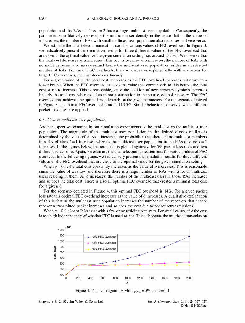
Another aspect we examine in our simulation experiments is the total cost vs the multicast userpopulation. The magnitude of the multicast user population in the defined classes of RAs isdetermined by the value of �. As � increases, the probability that there are no multicast membersin a RA of class i =1 increases whereas the multicast user population in the RAs of class i =2increases. In the figures below, the total cost is plotted against � for 5% packet loss rates and twodifferent values of �. Again, we estimate the total telecommunication cost for various values of FECoverhead. In the following figures, we indicatively present the simulation results for three differentvalues of the FEC overhead that are close to the optimal value for the given simulation setting.
When �=0.1, the total cost constantly increases as the value of � increases. This is reasonablesince the value of � is low and therefore there is a large number of RAs with a lot of multicastusers residing in them. As � increases, the number of the multicast users in those RAs increasesand so does the total cost. There is also an optimal FEC overhead that creates a minimal total costfor a given �.
For the scenario depicted in Figure 4, this optimal FEC overhead is 14%. For a given packetloss rate this optimal FEC overhead increases as the value of � increases. A qualitative explanationof this is that as the multicast user population increases the number of the receivers that cannotrecover a transmitted packet increases and so does the cost due to packet retransmissions.
When �=0.9 a lot of RAs exist with a few or no residing receivers. For small values of � the costis too high independently of whether FEC is used or not. This is because the multicast transmission
Figure 4. Total cost against � when ploss =5% and �=0.1.
Copyright � 2010 John Wiley & Sons, Ltd. Int. J. Commun. Syst. 2011; 24:607–627DOI: 10.1002/dac

A STUDY OF FEC FOR MOBILE MULTICAST 621
Figure 5. Total cost against � when ploss =5% and �=0.9.
Figure 6. Optimal overhead against packet loss rate when �=0.1.
cost does not depend on the number of the actual receivers, but it depends on the number of thecells where they reside. As � increases, the multicast population increases and the total cost doesthe same. It should be noted that the optimal FEC overhead increases as � increases (Figure 5).
6.3. Optimal overhead vs packet loss rate
Finally, experiment related to the cost analysis is the evaluation of the optimal overhead againstthe applied packet loss rate. In Figure 6 we observe that the optimal overhead of recovery symbolsincreases as the packet loss probability increases. For ploss>1%, the increase is linear with gradientaround 1.3. For small values of ploss, the optimal overhead rapidly increases as the packet lossrate increases. This is caused owing to the poor effectiveness of Raptor codes for small numberof recovery symbols.
6.4. Power control for streaming delivery
For the assessment of streaming delivery method the delivery of a media data stream of 64 kbps bitrate with BLER target set to 1% over both HS-DSCH and FACH channels is simulated. It should beclarified that the BLER target is the BLER that results after the FEC decoding at the receiver andis determined by the probability pf(m,k). This means that the actual BLER at the radio channelmight be larger than 1%.
In the case of transmission over HS-DSCH, four scenarios are examined:
1. Streaming delivery over HS-DSCH channel without FEC and channel BLER set to 1%.2. Streaming delivery over HS-DSCH channel with FEC and channel BLER set to 5%.3. Streaming delivery over HS-DSCH channel with FEC and channel BLER set to 10%.4. Streaming delivery over HS-DSCH channel with FEC and channel BLER set to 20%.
Copyright � 2010 John Wiley & Sons, Ltd. Int. J. Commun. Syst. 2011; 24:607–627DOI: 10.1002/dac

622 A. ALEXIOU, C. BOURAS AND A. PAPAZOIS
Figure 7. Average transmission power for the delivery of a 64 kbps media stream. BLER target is set to 1%.
In the three latter cases the BLER target after the FEC decoding at the receiver is set to therequired one (i.e. 1%).
P-t-p transmissions over HS-DSCH are more efficient for a limited number of users. In casethe number of receivers exceeds a certain threshold, the application of p-t-m transmission isrecommended [16]. Therefore, in our analysis we use the power levels of p-t-m transmission overFACH as a reference for an efficient channel selection. In more detail, the delivery of the samemedia stream over FACH without application layer FEC has also been simulated. The BLERapplied at this type of transmission is also set to the target of 1%.
The simulation results for the streaming delivery method are illustrated in Figure 7. Figure 7shows the required transmission power to deliver the 64 kbps media stream over the examinedchannels as a function of the number of receivers. The three levels of FACH transmission powerillustrated in Figure 7 correspond to the required power for the percentages of cell coverage (70,90, and 100%) that are indicatively selected and are presented in Table II.
What can be easily observed in Figure 7 is that for relatively large number of receivers, theaddition of FEC encoding increases the required transmission power. For instance, the delivery ofthe media stream to eight MBMS users over an HS-DSCH channel with 20% BLER requires 47%more power than the delivery over an HS-DSCH channel with 1% BLER. Therefore, the incrementin power consumption that is caused by the redundant symbols of FEC encoding with Raptorcodes is much higher in comparison with the increment needed in order to achieve a lower BLER.On the other hand, in the case of relatively small number of receivers, the required power for thetransmission with FEC encoding closely matches the required power when no FEC is supported.
Finally, our experimental results show that when the number of receivers exceeds a certainthreshold, the power consumption of HS-DSCH increases rapidly, thus the application of p-t-mtransmission becomes more efficient. For the examined network configuration, this threshold is10 to 11 multicast receivers depending on the BLER which is applied.
6.5. Power control for download delivery
The basic scenario that we simulate for the evaluation of FEC power efficiency during downloaddelivery is that a file of a certain size with static contents is transmitted in multicast mode toa group of users which are randomly placed in each serving cell. We have chosen to simulatethe distribution of a 512 kB file, which might represent a short multimedia clip, a still image, ora reasonably sized ring tone. For the finally presented results, bearers supporting 64 kbps havebeen chosen. Simulations are run for various numbers of MBMS receivers per cell, whereby theirstarting position is randomly and uniformly distributed over each cell area.
Copyright � 2010 John Wiley & Sons, Ltd. Int. J. Commun. Syst. 2011; 24:607–627DOI: 10.1002/dac

A STUDY OF FEC FOR MOBILE MULTICAST 623
Our scheme for download delivery method uses both HS-DSCH and FACH channels for thetransmission of data files. Contrary to the streaming delivery simulation, application layer FECwith Raptor codes is applied over both types of transport channels. In the assessment of the variouschannel configurations for the download delivery method, basically three aspects are of majorinterest: the required transmission power, the consumed transmission energy, and the necessarydownload time.
The required transmission power is almost the same as that of streaming delivery case, which isdepicted in Figure 7. Some minor differences exist and are caused by the sizes of the MBMS UserServices packet headers (RTP vs FLUTE) as depicted in Figure 2. In fact, the streaming protocolheaders are simpler and therefore a slightly less transmission power is needed in comparison withthe protocol headers used for the download service. The results for average total transmissionpower during download data delivery are not depicted due to space limitations and the reader isreferred to Figure 7.
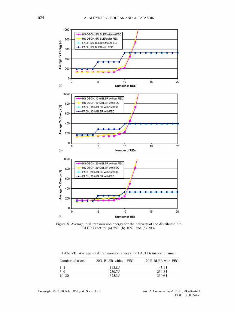
The other aspect that we examine during our simulation experiments is the consumed trans-mission energy. The minimization of energy consumption for the transmission of a given dataportion is an important goal for mobile operators and therefore the required transmission energyis a critical metric. During our assessment different BLER are applied over the channels and theenergy requirements of each channel configuration is examined for various users’ distributions.The BLER that are applied are 5, 10, and 20%. The required energy is estimated in terms of Joules(J) where 1J=1W1s. The results of our simulations are presented in the following figures.
From the simulation results it is immediately observed that, from transmission energy point ofview, the switching point where the p-t-m transmission over FACH turns to be more efficient is anumber of 10–11 mobile users. In more detail, all the simulation results show that the downloaddelivery over HS-DSCH is more expensive when the UEs are more than 10. The transmission overFACH even with 100% cell coverage is more efficient from energy perspective as the receiversbecome more than 10.
Another interesting observation is that the use of application layer FEC adds a minor overheadat the total transmission energy over the p-t-m channel. Although this overhead is not clear fromFigure 8 where the two curves almost coincide, the simulation logs show that this overhead variesfrom 1.1 to 1.5%. Nevertheless, during p-t-m transmission the 64 kbps bit rate level has to be keptand, since FEC encoding adds redundant symbols to the source data, a longer transmission time isnecessary for the delivery of the distributed file. The corresponding measurements are also listedin Table VII.
On the other hand, when the transmission is made over p-t-p channel (HS-DSCH) there isthe flexibility to achieve a download time that corresponds to 64 kbps bit rate. Therefore, thetransmission of the total amount of the encoding symbols (encoding symbols are the sourcesymbols plus the redundant ones added due to the FEC encoding) is performed at the higher bitrate. This causes an increment in the p-t-p total transmission energy from 10 to 25% (Figure 8).From the above results it is obvious that for non time-constrained transmissions it is considerablyadvantageous to keep the transmission energy low.
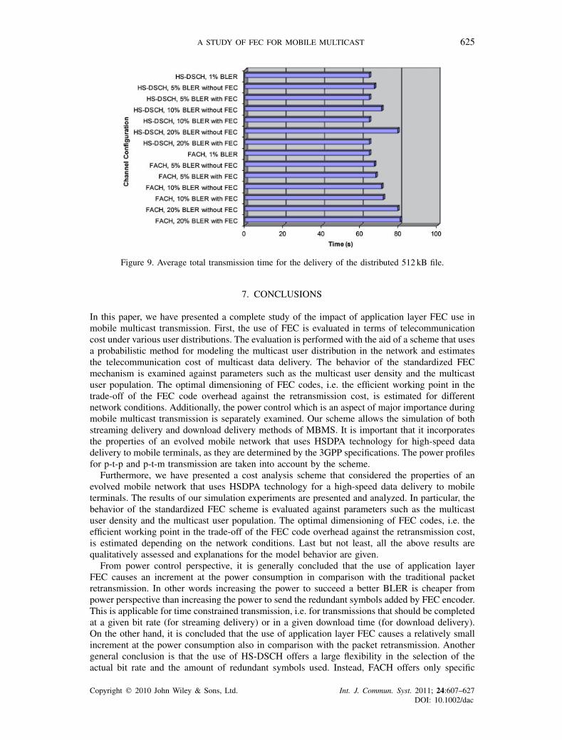
In terms of users perception, file download is in some sense only binary, namely it is evaluatedif the file is correctly received or not. On the other hand, there is an aspect that can be consideredas strongly connected with user perception: that is, the experienced download time. In other words,we evaluate how long it takes to receive the file after the joining has happened. Figure 9 presentsthe average experienced download time for each channel configuration.
When comparing the average download times for the various channel configurations, we concludethat using a p-t-m channel can be more time consuming. This is reasonable since a fixed bitrate level of 64 kbps has to be followed. This means that any redundant symbols added by theFEC encoding or any additional packet retransmissions cause an extension of the user perceiveddownload time.
On the other hand, the p-t-p channel offers the flexibility to regulate the transmission bit rateto any desired level. Therefore, by increasing the transmission power any additional redundantsymbols or any retransmitted packets are transferred without affecting the actual bit rate of 64 kbps.
Copyright � 2010 John Wiley & Sons, Ltd. Int. J. Commun. Syst. 2011; 24:607–627DOI: 10.1002/dac
624 A. ALEXIOU, C. BOURAS AND A. PAPAZOIS
Figure 8. Average total transmission energy for the delivery of the distributed file.BLER is set to: (a) 5%; (b) 10%; and (c) 20%.
Table VII. Average total transmission energy for FACH transport channel.
Number of users 20% BLER without FEC 20% BLER with FEC
1–4 142.8 J 145.1 J5–9 250.7 J 254.8 J10–20 325.3 J 330.6 J
Copyright � 2010 John Wiley & Sons, Ltd. Int. J. Commun. Syst. 2011; 24:607–627DOI: 10.1002/dac
A STUDY OF FEC FOR MOBILE MULTICAST 625
Figure 9. Average total transmission time for the delivery of the distributed 512 kB file.
7. CONCLUSIONS
In this paper, we have presented a complete study of the impact of application layer FEC use inmobile multicast transmission. First, the use of FEC is evaluated in terms of telecommunicationcost under various user distributions. The evaluation is performed with the aid of a scheme that usesa probabilistic method for modeling the multicast user distribution in the network and estimatesthe telecommunication cost of multicast data delivery. The behavior of the standardized FECmechanism is examined against parameters such as the multicast user density and the multicastuser population. The optimal dimensioning of FEC codes, i.e. the efficient working point in thetrade-off of the FEC code overhead against the retransmission cost, is estimated for differentnetwork conditions. Additionally, the power control which is an aspect of major importance duringmobile multicast transmission is separately examined. Our scheme allows the simulation of bothstreaming delivery and download delivery methods of MBMS. It is important that it incorporatesthe properties of an evolved mobile network that uses HSDPA technology for high-speed datadelivery to mobile terminals, as they are determined by the 3GPP specifications. The power profilesfor p-t-p and p-t-m transmission are taken into account by the scheme.
Furthermore, we have presented a cost analysis scheme that considered the properties of anevolved mobile network that uses HSDPA technology for a high-speed data delivery to mobileterminals. The results of our simulation experiments are presented and analyzed. In particular, thebehavior of the standardized FEC scheme is evaluated against parameters such as the multicastuser density and the multicast user population. The optimal dimensioning of FEC codes, i.e. theefficient working point in the trade-off of the FEC code overhead against the retransmission cost,is estimated depending on the network conditions. Last but not least, all the above results arequalitatively assessed and explanations for the model behavior are given.
From power control perspective, it is generally concluded that the use of application layerFEC causes an increment at the power consumption in comparison with the traditional packetretransmission. In other words increasing the power to succeed a better BLER is cheaper frompower perspective than increasing the power to send the redundant symbols added by FEC encoder.This is applicable for time constrained transmission, i.e. for transmissions that should be completedat a given bit rate (for streaming delivery) or in a given download time (for download delivery).On the other hand, it is concluded that the use of application layer FEC causes a relatively smallincrement at the power consumption also in comparison with the packet retransmission. Anothergeneral conclusion is that the use of HS-DSCH offers a large flexibility in the selection of theactual bit rate and the amount of redundant symbols used. Instead, FACH offers only specific
Copyright � 2010 John Wiley & Sons, Ltd. Int. J. Commun. Syst. 2011; 24:607–627DOI: 10.1002/dac
626 A. ALEXIOU, C. BOURAS AND A. PAPAZOIS
bit rate levels. The use of Raptor codes FEC encoding does not therefore offer downlink powersavings. Instead, the benefits of FEC are strongly connected with the uplink direction, mainly withits operability even with limited or no uplink resources and the avoidance of feedback implosionthat it offers.
In the case of streaming delivery service our experimental results show that when the number ofreceivers exceeds the threshold of 10 to 11 users, the power consumption of HS-DSCH increasesrapidly, thus the application of p-t-m transmission over FACH becomes more efficient. The eval-uation of FEC encoding for download delivery service shows that in terms of power consumptionthe figures for download delivery closely match those of streaming delivery. From energy pointof view, the switching point where the p-t-m transmission over FACH turns to be more efficientis a number of 10 to 11 mobile users. Therefore, it is clear that both from energy and powerperspective the switching point for download delivery method is the same. The final aspect thatwe have examined is the total transmission time. Its importance stems from its association withuser perception since it matches the user experienced download time. The evaluation of the totaltransmission time shows that the use of p-t-m channel can be more time consuming since a fixedbit rate level of 64 kbps has to be followed. This means that any redundant symbols added by theFEC encoding or any additional packet retransmissions cause an extension of the user perceiveddownload time. This does not happen in the case of the p-t-p channel due to the flexibility that itoffers to regulate the transmission bit rate to any desired level.
8. FUTURE WORK
The step that follows this work may be the modeling and implementation of a mechanism thatmakes efficient selection of the amount of application layer FEC encoding for mobile networks.This mechanism would monitor the network conditions and use them as input in order to select theappropriate amount of redundant symbols for FEC encoding and regulate the transmission powerto an optimal level. The results presented in this study against parameters such as the BLER inthe RAN, the multicast user population, and density can be used as input in order to make anefficient application of Raptor codes and choose the optimal transport channel and transmissionpower level in the RAN.
Another idea would be the investigation of the impact of FEC encoding over the Long TermEvolution (LTE) networks. The key feature for the provision of MBMS in LTE networks is theMultimedia Broadcast over a Single Frequency Network (MBSFN), where a time-synchronizedcommon waveform is transmitted from multiple cells. MBSFN is an interesting domain for futureresearch where the first steps are currently performed. The work presented in this paper may beused as a platform to examine the impact of application layer FEC in the next generation networks.
REFERENCES
1. 3GPP. TS 23.246 V9.3.0. Technical Specification Group Services and System Aspects; MBMS; Architecture andFunctional Description (Release 9). December 2009.
2. Tan WT, Zakhor A. Video multicast using layered FEC and scalable compression. IEEE Transactions on Circuitsand Systems for Video Technology 2001; 11(3):373–386. DOI: 10.1109/76.911162.
3. Luby M, Watson M, Gasiba T, Stockhammer T, Wen W. Raptor codes for reliable download delivery in wirelessbroadcast systems. Proceedings of the CCNC 2006, Las Vegas, NV, U.S.A., vol. 1, 8–10 January 2006; 192–197.
4. Hepsaydir E, Witvoet E, Binucci N, Jadhav S. Enhanced MBMS in UMTS networks and raptor codes. Proceedingsof the PIMRC 2007, Athens, Greece, 3–7 September 2007; 1–5. DOI: 10.1109/PIMRC.2007.4394642.
5. Luby M, Gasiba T, Stockhammer T, Watson M. Reliable multimedia download delivery in cellular broadcastnetworks. IEEE Transactions on Broadcasting 2007; 53(1):235–246. DOI: 10.1109/TBC.2007.891703.
6. Lohmar T, Peng Z, Mahonen P. Performance evaluation of a file repair procedure based on a combination ofMBMS and unicast bearers. Proceedings of the WoWMoM 2006, Niagara-Falls, Buffalo, NY, U.S.A., 26–29 June2006; 349–357. DOI: 10.1109/WOWMOM.2006.86.
7. Wang N, Zhang Z. The impact of application layer Raptor FEC on the coverage of MBMS. Proceedings of theRWS 2008, Orlando, FL, U.S.A., 22–24 January 2008; 223–226. DOI: 10.1109/RWS.2008.4463469.
8. Holma H, Toskala A. WCDMA for UMTS: HSPA Evolution and LTE (4th edn). Wiley: New York, 2007.
Copyright � 2010 John Wiley & Sons, Ltd. Int. J. Commun. Syst. 2011; 24:607–627DOI: 10.1002/dac

A STUDY OF FEC FOR MOBILE MULTICAST 627
9. 3GPP. TS 25.346 V8.3.0. Technical Specification Group RAN; Introduction of the MBMS in the RAN; Stage 2(Release 8). March 2009.
10. Dahlman E, Parkvall S, Sköld J, Beming P. 3G Evolution: HSPA and LTE for Mobile Broadband (2nd edn).Elsevier: Amsterdam, 2008.
11. 3GPP. TS 25.308 V9.1.0. Technical Specification Group Radio Access Network; High Speed Downlink PacketAccess (HSDPA); Overall Description; Stage 2 (Release 9). September 2009.
12. 3GPP. TR 25.803 V6.0.0, Technical Specification Group Radio Access Network; S-CCPCH Performance forMBMS; (Release 6). September 2005.
13. 3GPP. TS 26.346 V9.1.0 Technical Specification Group Services and System Aspects; MBMS; Protocols andcodecs (Release 9). December 2009.
14. Rümmler R, Chung YW, Aghvami AH. Modeling and analysis of an efficient multicast mechanism for UMTS.IEEE Transactions on Vehicular Technology 2005; 54(1):350–365. DOI: 10.1109/TVT.2004.836893.
15. Alexiou Bouras C. Multicast in UMTS: evaluation and recommendations. Wireless Communications and MobileComputing 2006; 8(4):463–481. DOI: 10.1002/wcm.464.
16. Alexiou A, Bouras C, Kokkinos V, Rekkas E. An improved mechanism for multiple MBMS sessions assignmentin B3G cellular networks. Wireless Networks 2009 (Published online). DOI: 10.1007/s11276-009-0161-6.
AUTHORS’ BIOGRAPHIES
Antonios Alexiou obtained his Diploma from the Department of Electrical and ComputerEngineering of the Aristotle University of Thessaloniki (Greece). Furthermore, heobtained his Masters Degree and his PhD from the Computer Engineering and InformaticsDepartment of Patras University (Greece). His research interests include data networks,mobile telecommunications networks, multicast routing and group management, radioresource management, radio network planning and optimization, wireless networks. Hehas published over 40 papers in Journals, International Conferences and Book Chapters.
Christos Bouras obtained his Diploma and PhD from the Computer Science and Engi-neering Department of Patras University (Greece). He is currently a Professor in theabove department. Also he is a scientific advisor of Research Unit 6 in the ResearchAcademic Computer Technology Institute (CTI), Patras, Greece. His research inter-ests include Analysis of Performance of Networking and Computer Systems, ComputerNetworks and Protocols, Telematics and New Services, QoS and Pricing for Networksand Services, e—learning, Networked Virtual Environments and WWW Issues. He hasextended professional experience in Design and Analysis of Networks, Protocols, Telem-atics and New Services. He has published more than 400 papers in various well-knownrefereed books, conferences and journals. He is a co-author of 8 books in Greek. He hasbeen a PC member and referee in various international journals and conferences. He hasparticipated in R&D projects such as RACE, ESPRIT, TELEMATICS, EDUCATIONAL
MULTIMEDIA, ISPO, EMPLOYMENT, ADAPT, STRIDE, EUROFORM, IST, GROWTH and others. Alsohe is a member of experts in the Greek Research and Technology Network (GRNET), Advisory CommitteeMember to the World Wide Web Consortium (W3C), IEEE—CS Technical Committee on Learning Technolo-gies, IEEE ComSoc Radio Communications Committee, IASTED Technical Committee on Education W 6.4Internet Applications Engineering of IFIP, ACM, IEEE, EDEN, AACE, New York Academy of Sciences andTechnical Chamber of Greece.
Andreas Papazois obtained his Diploma, Master’s Degree and PhD from the ComputerEngineering and Informatics Department of Patras University (Greece). He has workedas Telecommunication Systems Engineer at Intracom Telecom S.A. and he is currentlyworking as a Research Associate in the Research Unit 6 of Research Academic ComputerTechnology Institute. His research interests include Mobile Telecommunication Networks,Quality of Service, Forward Error Correction and Congestion Control during Multi-cast Transmission. He has published several research papers in well-known refereedinternational conferences and scientific journals and a book chapter.
Copyright � 2010 John Wiley & Sons, Ltd. Int. J. Commun. Syst. 2011; 24:607–627DOI: 10.1002/dac