A study of electromagnet moving-coil galvanometers for...
38
A STUDY OF ELECTROMAGNET MOVING COIL GAL- VANOMETERS FOR USE IN ALTERNATING- CURRENT MEASUREMENTS By Ernest Weibel CONTENTS Page I. Introduction '. 23 II. Theory 25 1. Assumptions 25 2. Notation 26 3. Equation of motion 27 4. Simple case 30 5. Effects of reactance 32 6. Effects of harmonics 35 7. Determination of constants 35 8. Disturbing torques 39 III. Construction and performance; 42 1. General design 42 2. Galvanometer A 44 3. Galvanometer B 45 4. Galvanometer C 46 5. Galvanometer D 47 IV. Uses 51 1. Detector 51 2. Other uses 55 V. Summary 57 I. INTRODUCTION The increasing use of alternating-current bridge and potentiom- eter methods of measurement emphasizes the need of an instru- ment for the detection and measurement of small alternating voltages. Instruments which have been used for this purpose are: The telephone receiver, the vibration galvanometer, the commutated direct-current galvanometer, the series and separately excited electrodynamometer, the vibration string galvanometer, and the vibration electrometer. Of these the telephone receiver and the vibration galvanometer are in most common use. The 23
Transcript of A study of electromagnet moving-coil galvanometers for...

A STUDY OF ELECTROMAGNET MOVING COIL GAL-VANOMETERS FOR USE IN ALTERNATING-
CURRENT MEASUREMENTS
By Ernest Weibel
CONTENTSPage
I. Introduction '.
23II. Theory 25
1. Assumptions 25
2. Notation 26
3. Equation of motion 27
4. Simple case 30
5. Effects of reactance 32
6. Effects of harmonics 357. Determination of constants 358. Disturbing torques 39
III. Construction and performance; 42
1. General design 42
2. Galvanometer A 44
3. Galvanometer B 45
4. Galvanometer C 46
5. Galvanometer D 47IV. Uses 51
1. Detector 51
2. Other uses 55
V. Summary 57
I. INTRODUCTION
The increasing use of alternating-current bridge and potentiom-
eter methods of measurement emphasizes the need of an instru-
ment for the detection and measurement of small alternating
voltages. Instruments which have been used for this purpose
are: The telephone receiver, the vibration galvanometer, the
commutated direct-current galvanometer, the series and separately
excited electrodynamometer, the vibration string galvanometer,
and the vibration electrometer. Of these the telephone receiver
and the vibration galvanometer are in most common use. The
23
24 Bulletin of the Bureau of Standards {Voi. 14
performances of the different instruments are so very different
that some are more suitable for certain measurements than others.
None of the instruments yet constructed has as good a performance
as the sensitive moving coil galvanometers used in the correspond-
ing direct-current measurements.
The separately excited electrodynamometer has been used to
some extent as an alternating-current galvanometer, but usually
the instruments were originally constructed for use in accurate
measurements by deflection methods and therefore on account of
the stiff suspensions, large coils, weak fields, etc., were not very
sensitive. Rowland ^ used the electrodynamometer as a detector
in various alternating-current bridge measurements of resistance,
inductance, and capacity, but his instruments were not very
sensitive. A more sensitive one has recently been designed byPalm.^
Stroud and Oates ' were the first to use a moving coil galvanom-
eter with an electromagnet excited by alternating current. This
was found to be very sensitive and was used in bridge measure-
ments of inductance and capacity. They observed effects due
to the induced currents in the moving coil and in the frame on
which the coil was wound and found that it was necessary to workwith a false zero. The complete explanation of the effects ob-
serV'Cd was not given.
Sumpner and Phillips^ designed iron-cored instruments anddevised a number of methods of measurements, using them sepa-
rately excited as detectors. Sumpner ^ gave special attention to
the design of alternating-current electromagnets in which the
magnetic flux is very nearly in quadrature with the impressed
voltage. Gloving coil instruments with such electromagnets were
found to be useful in measurements by deflection methods.
H. Abraham® in 1906 described briefly an electromagnet moving
coil galvanometer and showed that its performance depended
upon the constants of the moving coil circuit. The effects of
electromagnetic damping were obser^^ed and it was found possible
by suitable adjustment of the constants of the moving coil circuit
to make the motion aperiodic. He also observed that, on account
of the induced current, the period and hence the sensitivity
1 Ph>-sical Papers, pp. 294. 314: 1897-
' Zeit. Instr. 83, p. 36S, 1913; 84, p. 2S1, 1914.
» Phil. Mag.. 6. p. 707; 1903-
* Proc. Phv-s. Soc.. 22, p. 395; 190S.
* Proc. Roi'. Soc.. SO. p. 310. i9o3; Jour. Inst. E. E.. 86, p. 421, 1905.
•Comptes Rendus, 142. p. 993; 1906.

Weibeii Electromagnet Galvanometer 25
depended upon the reactance of the moving coil circuit. Hefound that, by compensating for the inductance of the movingcoil by means of a suitable condenser in parallel with a resistance,
the effect of the induced current could be made zero. This
method of compensation for inductance was pointed out before bySumpner ^ and applied to telephone circuits. The same methodwas used by Trowbridge at the University of Wisconsin in 1905 to
compensate for the inductance of the moving coil of an electro-
magnet galvanometer. Rosa^ used this method in 1906 to com-pensate for the inductance of the moving coil of an electrodyna-
mometer.
The step from the separately excited electrodynamometer to
the electromagnet moving coil galvanometer is a natural one in
the development of a sensitive alternating-current galvanometer.
The use of iron in the fixed coil of the instriunent results in a
marked increase in the strength of the magnetic field, so that the
induced current is sufficient to affect the performance. It wastherefore considered necessary for the proper design, construction,
and use of such instruments to make a theoretical study taking
these effects into account. The investigation has led to the con-
struction of instrmnents having sensitivities much greater than
those previously obtained and equal to those of the best permanent
magnet moving coil galvanometers for direct-current measure-
ments. The high sensitivity and good values for the other work-
ing constants result from the use of a strong magnetic field and a
moving system properly designed for the conditions of use.
Methods of testing and using have been worked out. The use of
such instruments is not as simple as that of the telephone receiver
or the vibration galvanometer, but it is believed that in manycases the gain in sensitivity and usefulness more than compensates
for the trouble involved.
II. THEORY
1. ASSUMPTIONS
In order to determine the operation of electromagnet moving
coil galvanometers of various kinds and under various conditions
it was necessary to derive the general equation of motion of a coil
carrying an alternating current in an alternating magnetic field.
To do this it is necessary to consider all of the torques acting on
the moving coil.
' Journ. Soc. Tel. Eng.. 16. p. 344; 1887. » This Bulletin, 8, p. 43; 1907.
26 Bulletin of the Bureau of Standards [va. 14
In most cases the mo\'ing coil is made of fine wire, so that the
assimiption of a linear moving coil circuit introduces no appreciable
errors arising from the variation of the current distribution in the
cross section of the wire. Therefore, we consider the electro-
magnet mo\-ing coil galvanometer to consist of a rigid linear
circuit suspended so as to rotate through a small angle in an alter-
nating magnetic field. The magnetic field will be assumed to be
approximately uniform and to have no rotating components •
around the axis, so that it is possible to turn the coil to a position
in which the resultant total magnetic flux is always zero. This is
the normal position of the coil and only small deflections from a
reference position near this will be considered.
2. NOTATION
To show the relations between the intrinsic constants, which
depend upon the construction, and the performance under certain
conditions it will be convenient to use the following symbols.
Unless otherwise stated the quantities are to be expressed in elec-
tromagnetic cgs units.
Symbol Quantity
f^=Angular deflection from reference position.
/=Tlme.
/iC=Moment oi inertia of moving svstem.
l>s:MtMiient of damping of moving sN-stem.
l/=Moment of restoration acting on moving system.
o:=2 r times the fundamental frequency.
«=Degree of the harmonic (n=i for fimdamental^.
^= Total instantaneous magnetic flux through the coil produced by the 9ep>arate
excitation.
G-=Rate of change with deflection of the effective value of the n^ harmonic of the
total flux.
aa=Fhase angle of lead of the n^ harmonic flux ahead of the fundamental flux.
^0=Deflection for no flux through the coil.
t=Total instantaneous current through the moving coil.
«i=Instantaneous value of the impressed electromotive force in the moving coil
circuit,
E2=Effective value of the n^ harmonic of the impressed electromotive force,
^B=Phase angle of lead of the «^ harmonic of the impressed electromotive force
ahead of the fundamental flux.
«,= Instantaneous induced electromotive force in coil.
Za=Impedance of the complete moving coil circuit to current of n^ harmonic
frequency.
7E=Phase angle of lead of the n^ harmomc of the current ahead of electromotive
force producing it.
* In ccBcraL tbe alteniatms field at any pomt in spacemay be oonsMiered asmadenp of twonualtematmc fieids at ri^t an^es and a ooostant rofatmc field always pcrpendicnlar to cne of tbeaci

Weibei] Electromagnet Galvanometer 27
T=Complete undamped (free) period of the moving system.
Ti=Complete period on open circuit.
X=logarithmic decrement.^"
Xi=Logarithmic decrement on open circuit.
5^=Sensitivity to w*^ harmonic electromotive force.
5=Sensitivity when critically damped.
r=Resistance of moving system.
i?^=Total resistance of moving coil circuit.
/?=External critical resistance.
3. EQUATION OF MOTION
Since, in general, there will be harmonics in the magnetic field
of the electromagnet depending upon the manner of excitation,
the flux through the moving coil due to the excitation is expressed
as
<f)=I> ^Gn(e -do) sin {no)t +an) (i)n=i
or this can be written
n= 00 n= 05
<^ =^ S -y/iGn sin (no)t +an) -^o 2 V^Gn sin (no)t +an) (2)n=i n—
I
Now the torque acting on the moving coil when the current i
flows is given by "
d(f)''-°' /-
i^=il^ yj2Gn sin (no:t +a:n) (3)n=i
On equating this to the sum of the moments due to angular
acceleration, damping, and restoration we obtain the differential
equation of motion
(Pd dd ^^°°
K-T7^ + D-T. +U6=ii: y/2Gn siu (no:t + an) (4)
The current in the moving coil can be considered to be the result
of two electromotive forces, the impressed electromotive force
and the induced electromotive force. If the impressed electro-
motive force contains harmonics and if it is in synchronism with
the magnetic field we can represent it by
n= 00
^1 = 2 ^J2Gn sin (ncot +Pn) (5)n=i
1" The logarithmic decrement is here taken to be the natural logarithm of the ratio of one deflection to the
following deflection in the opposite direction.
^1 The reason for neglecting the effect of the flux due to i is given on p. 40.

28 Bulletin of the Bureau of Standards
The induced electromotive force is
[Vol. 14
€2= --J. = -6Z V2najGn cos {nust 4- an)dt
dS"""^ r-— t; S \2Gn sm {rnct-Va^dt n-"i
n— 00
+^0 S ^ncoGnCOS (n<j3t+an)
(6)
giving for the total current
t= 2 ^^^'^ sin (n^/+/3n+7n)n=i ^n
_^"--V2«^n ^^^ ^^^^ ^^_^ ^^^^n=i •^n
O* n=i -^n
n=»i ^ n
Substituting in (3) we get for the moment of displacement
°S*^^"sin (no^t+Pn+yn)
(7)
2 ^Gu sin (w^/ +an)
= 1 ^n
^,f2no)Gne 2n=i -^n
COS (^u^jf +a:n+7D)
T. 2 ^^ ° sin (imt +an +7n)at 11=1 Zn
+ (9o 2°=r^^?ia)Gn
z,COS {noit+an+y,^
(8)
From this it follows that the resultant torque due to the alternat-
ing current and magnetic field of frequency — is the sum of a
constant torque (the average of the above) and a series of sinusoidal
torques of frequency — and higher. If, as is usually the case,
no even harmonics are present, the sinusoidal torques are of
frequency - and higher; that is, have frequencies equal to and
greater than twice the fimdamental frequency. Now, this is large
Weibei] Electromagnet Galvanometer 29
compared with i/T, so that the motion will be very nearly the sameas if a torque equal to the average of the above were acting. ^^
The average torque as calculated from the instantaneous torque
given above is
(9)
S —y COS (an-iSn-7n)+^ S -^ Sm 7nn=i ^n. 11=1 Z^n
de%^Gn' ^ "="nC0Gn^ .— -»T ^ ^ COS 7n —60 S ^; Sm 7n
We can now write the equation of motion as follows:
= S —^^ COS (an-/3n-7n) "^o S ^^ Sm 7nn=i -^n n= I ^n
which is of the form
where D', Z7' and jB depend upon the constants of the galvanometer
and the moving coil circuit and A depends upon the impressed
electromotive force in the moving coil circuit. This is the familiar
12 Actually the motion is the sum of the slow motion resulting from the average torque and a vibration
containing all of the harmonics to some extent. It can be expressed as a Fourier's series, but the coefficients
are very complicated functions of the intrinsic constants. The magnitude of the error in determining the
deflection due to the blurring of the image on account of the vibration of the coil can be estimated by in-
spection of the equation of motion for the simple case of sine wave flux and impressed electromotive force
which is
K^,+ (z?+f cos y) g+ (f/-^ sin t)e=^ cos ifi+y)-0j'-^ sin y-^ cos {2c.t+fi+y)
"ft Y <^OS(2cot+y)+(9-eop^ sin i2wt+y)
The maximum values of the alternating torques are
GE de G^ . ... . ,«(7»
and the vibration produced by these can be calculated approximately by the equation
where 4^' is the amplitude of the vibration and 4^ is the deflection which a constant torque equal to the maxi-
mum value of the alternating torque would produce. This formula is not correct when T approaches the
value -; that is, near mechanical resonance. It is interesting to note that with a tight suspension and a
small coil—that is, when T is small—the instnunent becomes a "vibration galvanometer" which may be
made to vibrate with twice the frequency of the magnetic field and hence be tuned to the frequency of the
alternating torques.

30 Bulletin of the Bureau of Standards [Voi. 14
equation of an oscillating system acted upon by the torques A and
B and the particular solution shows that the motion may be either
underdamped, aperiodic (critically damped or dead beat) or over-
damped according as {D^y is less than, equal to, or greater than
^U', The free period is
This is the undamped period and equals the time required for the
coil to deflect 99 per cent of the total deflection when critically
damped. It is therefore a measure of the speed of the instrument.
The logarithmic decrement is
The torques A and B produce deflections from the equilibrium
position equal to A/U' and BjU'
.
The period not only depends upon the moment of inertia of the
moving system and moment of restoration of the suspension, but
also upon the constants of the moving coil circuit and the excitation
and may be larger or smaller than the period without excitation.
The damping is always larger with excitation. The torque B pro-
duces a deflection of the coil from its equilibrium position even
w^hen there is no impressed electromotive force. This deflection
is proportional to the angle Bo and is due to the induced current in
the circuit. The torque A which results from the impressed
electromotive force produces a deflection depending upon the
magnitudes ot die harmonics in the excitation and in the electro-
motive force, upon the phase relations and upon the constants of
the moving coil circuit.
4. SIMPLE CASE
For the simple ideal case of a sine-wave magnetic field and a
sine wave of impressed electromotive force of the same frequency
the equation (10) reduces to
^A'B ( ^ G^ \dQ ( ^, o^G' . \^
GE ,, ^.coG^ .
^'4)
= -7- COS (j3+7) -Go—y- sm7
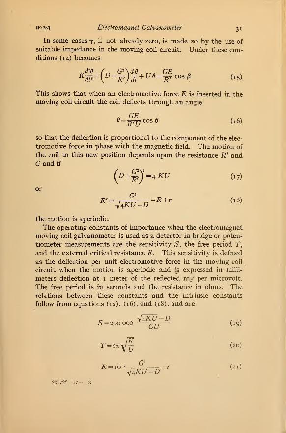
Weibeii Electromagnet Galvanometer 31
In some cases 7, if not already zero, is made so by the use of
suitable impedance in the moving coil circuit. Under these con-
ditions (14) becomes
This shows that when an electromotive force E is inserted in the
moving coil circuit the coil deflects through an angle
GEe==^7jj cos p (16)
so that the deflection is proportional to the component of the elec-
tromotive force in phase with the magnetic field. The motion of
the coil to this new position depends upon the resistance R^ andG and if
("-?) aKU (17)
or
the motion is aperiodic.
The operating constants of importance when the electromagnet
moving coil galvanometer is used as a detector in bridge or poten-
tiometer measurements are the sensitivity S, the free period T,
and the external critical resistance R. This sensitivity is defined
as the deflection per unit electromotive force in the moving coil
circuit when the motion is aperiodic and Is expressed in milli-
meters deflection at i meter of the reflected my per microvolt.
The free period is in seconds and the resistance in ohms. Therelations between these constants and the intrinsic constants
follow from equations (12), (16), and (18), and are
5 = 200000 -—^jj (19)
=Wf (20)
R = io-'-, —?'~^-r (21)^4KU-D
20172°—17 3
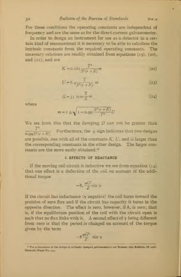
32 Bulletin of the Bureau of Standards W^t4
For these conditions the operating constants are independent of
frequency and are the same as for the direct-current galvanometer.
In order to design an instnmient for use as a detector in a cer-
tain kind of measurement it is necessary- to be able to calculate the
intrinsic constants from the required operating constants. Thenecessars' relations are readily obtained from equations (19), (20),
and (21), and are
TK =0.161-^ rn"* (22)
^' = 6-4 c^TT—^T ^ (23)
(24)
whereS" r--R)^
•1 = 1-^ 1-0.99 p—
^
We see from this that the damping D can not be greater than
^ _p\ ' Furthermore, the = sign indicates that two designs
are possible, one with all of the constants K. U, and G larger than
the corresponding constants in the other design. The larger con-
stants are the more easilv obtained."
5. EFFECTS OF REACTA:^CE
If the nio\-ing coil circuit is inductive we see from equation (14)
that one effect is a deflection of the coil on account of the addi-
tional torque
-^o-^sm7
If the circuit has inductance y negative • the coil turns toward the
position of zero flux and if the circuit has capacit>' it turns in the
opposite direction. The effect is zcto, however, if ^o is zero; that
is, if the equilibrium position of the coil with the circuit open is
such that no flux links with it. A second effect of y being different
from zero is that the period is changed on account of the torque
given by the term
— 9—y- sm 7
of eritJcaST dmnicJ ti*W"u—'tf ,i see Wenser. this BoDetm. U. i9x6l

weibet] Electromagnet Galvanometer 33
Thus if 7 is negative (lagging current) the period is shortened on
account of the increased restoring torque, and if 7 is positive the
period is lengthened. If the factor
-y- sin 7 becomes greater than U
the coil is in unstable equilibrium and will, if displaced slightly
from its zero position, turn suddenly toward a position at right
angles to the field. Stroud and Oates ^* observed the shortening of
the period, and the fact that the equilibrium position depends, in
general, upon the impedence of the moving coil circuit. A third
effect is the increase in damping, which for small angles of lead or
lag is negligible.
The change in the restoring torque resulting from the reactance
in the moving coil circuit causes a change in the period, damping,
and sensitivity according to the following relations:
T = 27r /K"^ sin 7 ('5)
IT (D +Y cos 7)
^4K(U-'^ sin y)-{D+^ cos 7)^ (26)
Si = 200 000 —Z(L/-^%in7) (27)
These follow immediately from equations (12), (13), and (14), and
give the performance of the electromagnet moving coil galvanom-
eter when the motion is underdamped.
When the damping D and the resistance r are small, the equa-
tions (19), (20), and (21) can be put in the more convenient form
=»vi (28)
_^^200000 T
(^^)
i? =^-'^ (30)47r A
'< Phil. Mag., 6, p. 707; 1903.

34 Bulletin of the Bureau of Standards [Voi. 14
and if the U becomes U - -y- sin 7 these become
/^
_, 200 000 T' T', ,5 ^=^5 (32)
showing that the period, sensitivity, and the external critical
resistance change in the same proportion when the constants of
the moving coil circuit are changed. We can therefore in this
manner change the operating constants of the instrument without
an actual change in the construction.
The intrinsic constants K, D, and U can readily be determined
for any particular galvanometer by methods described later.
G can also be determined by these methods for the value of
the excitation current used and being approximately propor-
tional to this current can be calculated for other values. If the
electromagnet moving coil galvanometer is to be used at a certain
frequency with apparatus having a known resistance and reac-
tance between its "galvanometer terminals," it is possible by the
use of equations (25), (26), and (27) to adjust Z, 7, and the excita-
tion to give the most satisfactory operation under the conditions
of use.
In the adjustment of Z and 7 to the best values it is sometimes
necessary to use series or parallel resistance, inductance, or capac-
ity. Sometimes the circuit containing the small electromotive
force to be measured has a reactance which is large compared with
its resistance, for example, a bridge for measuring large inductances
or small capacities. The general aim in these cases is to produce
an electrical resonating system ^^ so that the total reactance in the
moving coil circuit is zero or such a value as will give the best
operating constants. Obviously if such a system is used it is neces-
sary to maintain the frequency constant.
" Wenner, Weibel, and Silsbee, this Bulletin, 12, p. i8; 19x5.
weibeii Electromagnet Galvanometer 35
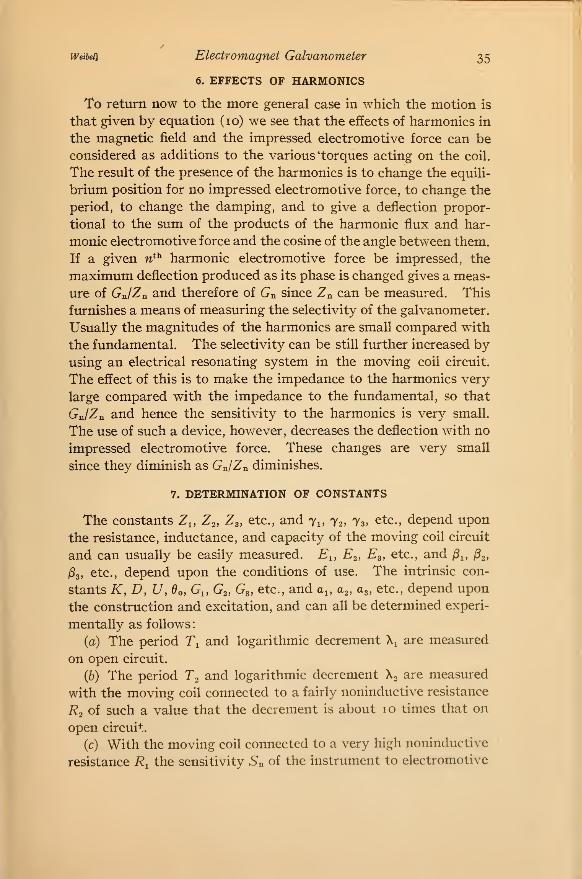
6. EFFECTS OF HARMONICS
To return now to the more general case in which the motion is
that given by equation (10) we see that the effects of harmonics in
the magnetic field and the impressed electromotive force can be
considered as additions to the various 'torques acting on the coil.
The result of the presence of the harmonics is to change the equili-
brium position for no impressed electromotive force, to change the
period, to change the damping, and to give a deflection propor-
tional to the sum of the products of the harmonic flux and har-
monic electromotive force and the cosine of the angle between them.
If a given n^^ harmonic electromotive force be impressed, the
maximum deflection produced as its phase is changed gives a meas-
ure of Gn/Zn and therefore of Gn since Zn can be measured. This
furnishes a means of measuring the selectivity of the galvanometer.
Usually the magnitudes of the harmonics are small compared with
the fundamental. The selectivity can be still further increased byusing an electrical resonating system in the moving coil circuit.
The effect of this is to make the impedance to the harmonics very
large compared with the impedance to the fundamental, so that
Gn/Zn and hence the sensitivity to the harmonics is very small.
The use of such a device, however, decreases the deflection with no
impressed electromotive force. These changes are very small
since they diminish as GJZn diminishes.
7. DETERMINATION OF CONSTANTS
The constants Z^, Z^, Z3, etc., and 71, 72, 73^ etc., depend upon
the resistance, inductance, and capacity of the moving coil circuit
and can usually be easily measured. E^, E2, E^, etc., and /3i, jSj,
jSs, etc., depend upon the conditions of use. The intrinsic con-
stants K, D, U, Oo, G„ G2, G3, etc., and a^, a^, a^, etc., depend upon
the construction and excitation, and can all be determined experi-
mentally as follows
:
(a) The period T^ and logarithmic decrement \ are measured
on open circuit.
(6) The period T^ and logarithmic decrement Xo are measured
with the moving coil connected to a fairly noninductive resistance
R2 of such a value that the decrement is about 10 times that on
open circuit.
(c) With the moving coil connected to a very high noninductive
resistance R^ the sensitivity Sn of the instrument to electromotive
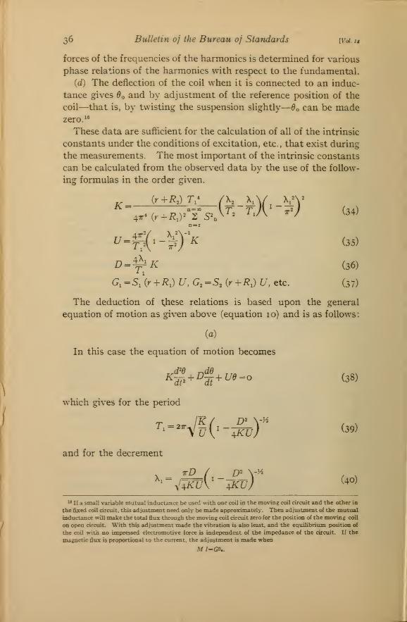
2,6 Bulletin of the Bureau of Standards [Voi. 14
forces of the frequencies of the harmonics is determined for various
phase relations of the harmonics with respect to the fundamental.
((f) The deflection of the coil when it is connected to an induc-
tance gives ^o and by adjustment of the reference position of the
coil—that is, by twisting the suspension slightly—^o can be madezero."
These data are sufficient for the calculation of all of the intrinsic
constants under the conditions of excitation, etc., that exist during
the measurements. The most important of the intrinsic constants
can be calculated from the observed data by the use of the follow-
ing: formulas in the order o:iven.
ri. — „__4jr* {r+R,y 2 S"^
t/ = i?ji
(rrTtX'-^) (34)
W^ (35)
d=y;K (36)
G,=s!{r^R,) U, G,=S, (r+RJ U, etc. (37)
The deduction of these relations is based upon the general
equation of motion as given above (equation 10) and is as follows:
(a)
In this case the equation of motion becomes
4^^l+^-^- (38)
T, = 2.^/^
which gives for the period
uV-WL-J ^^^^
and for the decrement
^-^V^'":^!/; ^i« If a small variable mutual inductance be used with one coil in the moving coil circuit and the other in
the fixed coil circuit, this adjustment need only be made approximately. Then adjustment of the mutual
inductance will make the total flux through the mo\-ing coil circuit zero for the pMjsition of the moN'ing coil
on op)en circuit. With this adjustment made the vibration is also least, and the equihbrium position of
the coil with no impressed electromotive force is independent of the impedance of the circuit. If the
magnetic flux is prot>ortional to the current, the adjustment is made when
M/=G5..
Weibd] Electromagnet Galvanometer
(.b)
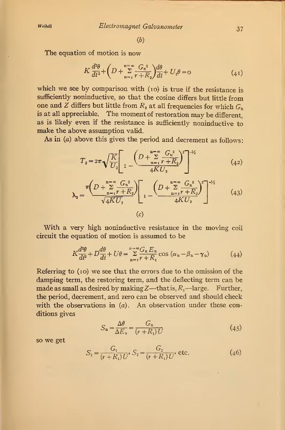
The equation of motion is now
dd
37
("n=Qo /;: 2
n^^r +RJdt + UJ=o (41)
which we see by comparison with (10) is true if the resistance is
sufficiently noninductive, so that the cosine differs but little fromone and Z differs but little from R^ at all frequencies for which Gnis at all appreciable. The moment of restoration may be different,
as is likely even if the resistance is sufficiently noninductive tomake the above assumption valid.
As in (a) above this gives the period and decrement as follows:
'^==Wf,
(n=oo /7 2 \2
n^.r+Rj4KU,
-Vi
= n-,r+RJ \ n~ir+RJaku.-hKU,
-V2
(42)
(43)
(c)
With a very high noninductive resistance in the moving coil
circuit the equation of motion is assumed to be
7n) (44)
Referring to (10) we see that the errors due to the omission of the
damping term, the restoring term, and the deflecting term can be
made as small as desired by makingZ—that is , R,^—large. Further,
the period, decrement, and zero can be observed and should check
with the observations in (a). An observation under these con-
ditions gives
Ad GnSn =
AEn {r+RJUso we get
5.=G,
»"T~r~r» S-y ={r+R,)U^' {r+R,)U
etc.
(45)
(46)
38 Bulletin of the Bureau of Standards \y0i.r4
id)
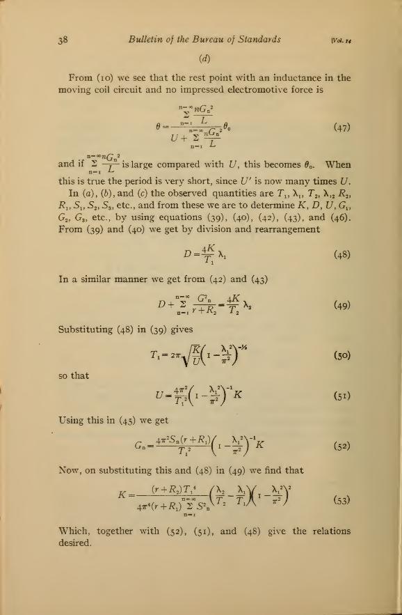
From (10) we see that the rest point with an inductance in the
moving coil circuit and no impressed electromotive force is
'"^''nGn'
n=ao /^ 2 (47)
and if S -y— is large compared with U, this becomes Bo. Whenn=i ^
this is true the period is very short, since U' is now many times U.
In (a), (6), and (c) the observed quantities are Tj, X^, T2, X,2 i^2.
i?i, 5i, 5,, Sa, etc., and from these we are to determine K, D, U^Gi,
Go, G3, etc., by using equations (39), (40), (42), (43), and (46).
From (39) and (40) we get by division and rearrangement
(48)z,.fx,
In a similar manner we get from (42)
n=i r+K2
and
+^x
(43)
(49)r , ^V2 X 2
Substituting (48) in (39) gives
so that
Using this in (45) we get
G. = '-'^p^\r-'^yK (5.)
Now, on substituting this and (48) in (49) we find that
4x-(r + i?.)°F5A^= r.A -; (53)
n=i
Which, together with (52), (51), and (48) give the relations
desired.
Weibei] Electromagnet Galvanometer 39
The phase angles a^, a^, cvg, etc., can be determined from the
observed phase changes necessary to give maximum (or zero, whichis more accurate) deflection for the various harmonics.
From a few observations it is therefore possible to obtain all of
the intrinsic constants and hence determine the performance of
the electromagnet moving coil galvanometer under various con-
ditions of use.
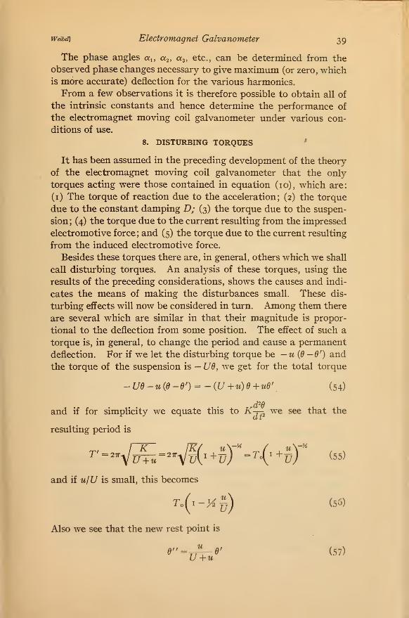
8. DISTURBING TORQUES '
It has been assumed in the preceding development of the theory
of the electromagnet moving coil galvanometer that the only
torques acting were those contained in equation (10), which are:
(i) The torque of reaction due to the acceleration; (2) the torque
due to the constant damping D; (3) the torque due to the suspen-
sion; (4) the torque due to the current resulting from the impressed
electromotive force; and (5) the torque due to the current resulting
from the induced electromotive force.
Besides these torques there are, in general, others which we shall
call disturbing torques. An analysis of these torques, using the
results of the preceding considerations, shows the causes and indi-
cates the means of making the disturbances small. These dis-
turbing effects will now be considered in turn. Among them there
are several which are similar in that their magnitude is propor-
tional to the deflection from some position. The efl'ect of such a
torque is, in general, to change the period and cause a permanent
deflection. For if we let the disturbing torque be —u(d—9') and
the torque of the suspension is —U6, we get for the total torque
-Ud -u{d -6') = - {U +u) +ud\ (54)
and if for simplicity we equate this to K-r- we see that the
resulting period is
and if u/U is small, this becomes
To(i-K5) (56)
Also we see that the new rest point is
^" = r7T-^' (57)U +u
40 Bulletin oj the Bureau oj Standards (v^x«
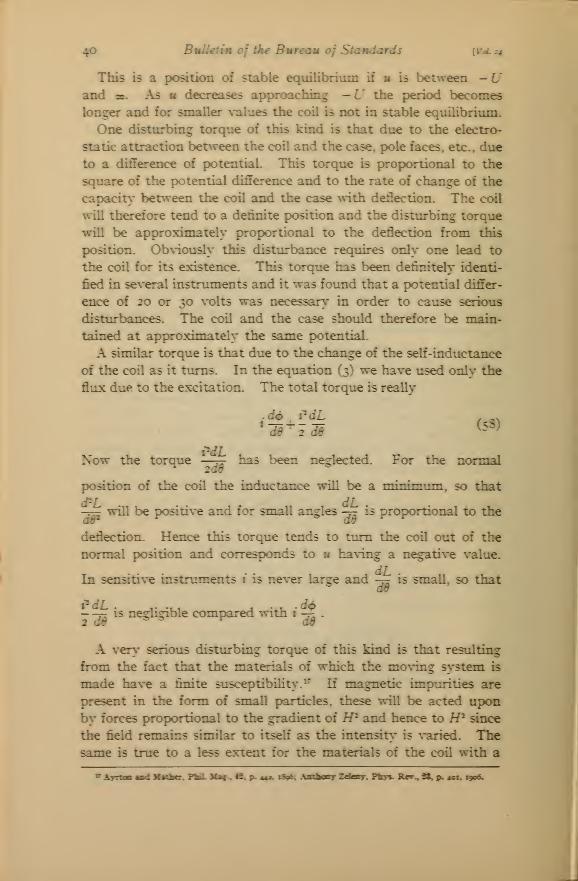
This is a position of stable equilibrium if m b between —Uand oc. As u decreases approaching —U the period becomes
longer and for smaller values the coil is not in stable equilibrium.
One disturbing torque of this kind is that due to the electro-
static attraction between the coil and the case, pole faces, etc., due
to a difference of potential. This torque is proportional to the
square of the potential difference and to the rate of change of the
capacity- bet^veen the coil and the case with deflection. The coil
will therefore tend to a definite position and the disturbing torque
will be approximately proportional to the deflection from this
position. Ob\-iously this disturbance requires only one lead to
the coil for its existence. This torque has been definitely identi-
fied in several instruments and it was foimd that a potential differ-
ence of 20 or 30 volts was necessary in order to cause serious
disturbances. The coil and the case should therefore be main-
tained at approximately the same potential.
A similar torque is that due to the change of the self-inductance
of the coil as it turns. In the equation (3) we have used only the
flux due to the excitation. The total torque is really
.d4> i'dL , „^
Now the torque —j^ has been neglected- For tbe ncnmal2ad
position of the coil the inductance will be a minimum, so that
-^ will be positive and for small angles -tt is proportional to the
deflection. Hence this torque tends to turn the coil out of the
normal position and corresponds to u having a negative \-alue.
In sensitive instnunents 1 is never large and -j^ is small, so thatdd
-- -5^ is negligible compared with i -^ .
A very serious disturbing torque of this kind is that resulting
from the fact that the materials of which the mo\Tng system is
made have a finite susceptibility'.^* If magnetic impurities are
present in the form of small particles, these will be acted uponby forces proportional to the gradient of IP and hence to H^ since
the field remains similar to itseh' as the intensit}' is \-aried. Thesame is true to a less extent for the materials of the coil with a
^ AvTtoa sad Mtfber. FU. Mac.. -fi. p^ 44a. lApiC ft tfcMj Zefagy. Pfcys- tUer^H, p. szz lycc.
Weibei] Electromagnet Galvanometer 41
susceptibility a little different from that of the surrounding air.
Now, the resultant torque will obviously be zero for some position
near the normal one, for usually the field is very nearly uniformand the lack of uniformity is symmetrical with respect to this
position. This disturbing torque is very evident in sensitive
instruments and, if care is not taken, may be much greater thanthat due to the suspension. The magnetic dirt which is usually
on the surface can be removed by suitable treatment (p. 45).
The magnetic field should be of suitable distribution. Thus, for
a moving system whose parts are cylindrical, with axes parallel
to the axis of rotation, a uniform field gives no torque. For other
shaped systems the field should be radial, with its center on the
axis of rotation of the coil.
A disturbing torque which is of this same kind is that resulting
from the capacity current between turns of the moving coil. Let
us replace this distributed capacity by a capacity localized at the
terminals. Then it follows from equation (14) that in the simple
case this would give a torque
"^ sin y (d- do) = c^'G'C {0 - do) (59)
which is directly proportional to the capacity, to the square of
the frequency, and to the square of the exciting current. Theonly remedy for this is to diminish the capacity between turns
by the use of thicker insulation or to diminish G by using fewer
tujrns. The effect of this torque is to diminish the total restoring
torque; that is, to lengthen the period so that it is only necessary
to change the external circuit constants to bring the control back
to its original value. The change of rest point is zero if ^0 is
zero, which can be made so by adjustment of either the coil or
the mutual inductance.
If there is an alternating potential difference between the case
and one terminal of the coil, there will be capacity current flowing
through the coil, at least in part, and if this current has a com-
ponent in phase with the magnetism, a torque acts tending to
deflect the coil. The torque is proportional to the potential
difference and has been observed to be very large in a sensitive
instrument when the potential difference was only 5 volts at a
frequency of 2100 cycles per second.
Other disturbing torques result from leakage and capacity cur-
rents between the parts of the moving coil circuit and external
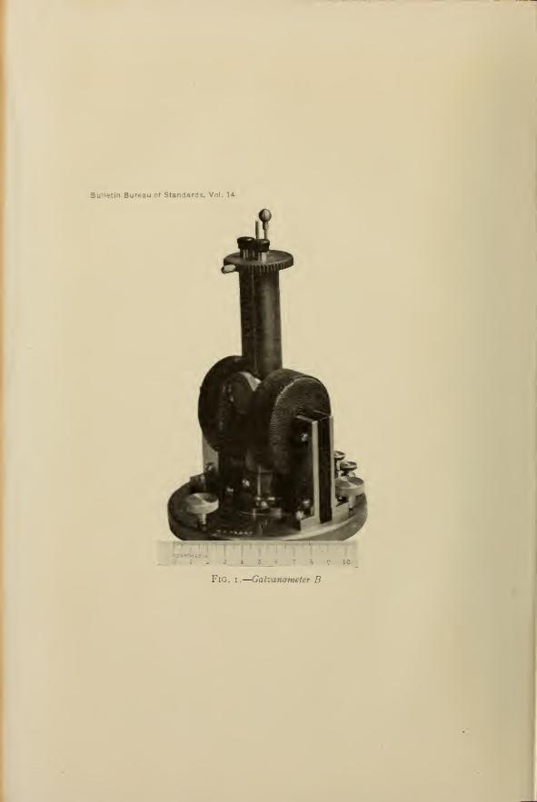
Bulletin Bureau of Standards. Vol. 1*
LKTIMETtR I I I ' I•
I
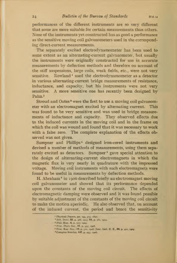
Fig. I.
—
Galvanometer B
J

42 Bulletin of the Bureau of Standards [Vol. 14
bodies which, on account of the inevitable dissymmetry in the two
leads to the coil, flow through the coil. These disturbances are
very serious at high frequencies when the capacity currents are
large. The remedy for these and many of the other disturbing
torques is the shielding scheme " shown in Fig. 2. The metallic
shield and the one coil of the mutual inductance are maintained
at a potential very nearly equal to the potential of the moving
coil circuit.
The problem of the elimination of the mechanical disturbances
is the same as for all instruments having delicate suspended
systems, the difficulties increasing as the sensitivity increases.
In extreme cases special attention is necessary in moimting the
instrument.
In the electromagnet moving coil galvanometer it is sometimes
necessary to use intense separate excitation, so that considerable
Shield
Fig. 2.
—
Shielding arrangement
heating is liable to occur. At low frequencies this occurs in the
copper wire of the exciting coil or coils and at high frequencies the
iron losses may be large. The exciting coils should always be
separated from the moving system by a shield, so that disturbances
caused by moving air will be minimized.
m. CONSTRUCTION AND PERFORMANCE
1. GENERAL DESIGN
The construction of an electromagnet moving coil galvanometer
for use in alternating-current measurements differs but little
from that of the sensitive moving coil galvanometer for direct
currents. In place of the permanent magnet a laminated elec-
tromagnet is used. The moving system can be the same as for
the direct-current galvanometer, with modifications suggested bythe analysis of the disturbing torques. By using equations (22),
(23), and (24), it is easy to calculate the values of the moment of
^ Price, Phil. 3Iag., 42, p. 150, 1896; White, Phys. Rev.. 25, p. 334, 1907.
Weibei] Electromagnet Galvanometer 43
inertia K, the moment of restoration U, and the moment of dis-
placement G necessary for an instrument which is to be used with
apparatus having a resistance between ''galvanometer" terminals
about equal to R and which is to have a sensitivity S and a period
T. The resistance r and the damping are assumed to be zero in
this preliminary calculation. A consideration of the construction
of such an instrument from the material available then allows
estimates of the probable values of r and D to be made, so that
more accurate values of the intrinsic constants can be computed.
In the construction of the moving system it is desirable to have
the resistance of the coil as low as possible and the material as
free from magnetic impurities as possible. The use of thin insu-
lating material (enameled wire) is desirable, for this keeps the
moment of inertia low. Furthermore, but little insulation is
needed. However, in case the instrument is to be used at high
frequencies the use of thin insulation increases the capacity be-
tween turns and hence the corresponding disturbing torque. Alarge mirror adds to the moment of inertia, but some sacrifice
is necessary if accurate readings are to be made easily. Muchcan be gained by the use of well-made mirror of good glass. Theresistance of the suspensions should be kept reasonably low.
Short, flat suspensions made by rolling small (0.02 mm) copper
wire have been found satisfactory.
The construction of the electromagnet should be such as to give
a field of the desired strength and shape with as little power loss
and distortion of the wave shape as possible. The strength of
the field is limited by the magnetic properties of the materials
used in the coil and also by the source of excitation available.
At high frequencies special attention is necessary to keep the losses
due to hysteresis and eddy currents low. It is also necessary to
design the exciting winding so that the higher voltages required
at the higher frequencies cause no trouble. It is desirable to have
the winding made up of several coils which can be connected in
series or parallel as the case demands.
Usually the reluctance of the air gap is large compared with
that of the iron and also low inductions (500-2000 gauss) are used
so that the production of harmonics in the magnetic flux depends
upon the source of excitation. Since the inductance of the fixed
coil is large compared with the resistance, the exciting current
and therefore the magnetic flux will contain fewer harmonics than
the impressed electromotive force. The magnitude of the har-
monics can be still further reduced by the use of a resonating
44 Bulletin of the Bureau of Standards [Vol. 14
system. A large inductance in series and a suitable condenser
in parallel with the coils improves the wave shape of the magnetic
flux and hence increases the selectivity of the instrument.^®
In order to shield the moving system of the galvanometer from
leakage and electrostatic effects, it is convenient to surround it
with a metallic case which is connected to some point in the test-
ing circuit such that the difference of potential between it andthe coil is always very small. This shield can also be the support
for the adjustment and arrestment devices, terminals, etc. Theiron core of the fixed coils should be connected electrically to the
shield.
Several sensitive galvanometers have been designed and built
following the ideas given above. The description of the con-
struction and the performances are given on the following pages.
2. GALVANOMETER A
The moving system of this instrument consists of a coil 8 mmwide and 12 mm high which has 2-]% turns of 0.08 mm (No. 40American wire gage) single silk-covered copper wire and a mirror
I cm in diameter and 0.6 mm in thickness. The upper and lower
suspensions are each about 5 cm long and were made from 0.015
mm copper wdre rolled flat.
The coil was suspended in an air gap 10 mm long between pole-
faces 8 mm square. The core of the fixed coil w^as made of lami-
nations of good silicon steel. The exciting coil consisted of 1560
turns of 0.51 mm (No. 24) enameled copper wdre. With 120 volts
at 60 cycles per second on this winding the current was 0.93
ampere and the performance was as shown in Table i . Here C is
the capacity of the condenser connected to the terminals of the
moving coil, T is the period of the instrument, R is the external
critical resistance, and 5co, S^^q, and ^300 are the sensitivities to the
fundamental, the third and the fifth harmonics, respectively. Theprediction of aperiodic motion is borne out, but it is noted that the
external resistance necessary to produce it is low.
TABLE 1
Performance of Galvanometer A
c T R Soo Siso S300
Ml
2
seconds
5.6
8.0
ohms
0.1
5.1
mm/MV13.5
16.0
mm/MV
0.13
mmVv0.015
Ryan, Trans. Am. Inst. E. E., 20, p. 1419; 1903.
Bulletin Bureau c* S*ariarjs. Vol. 14
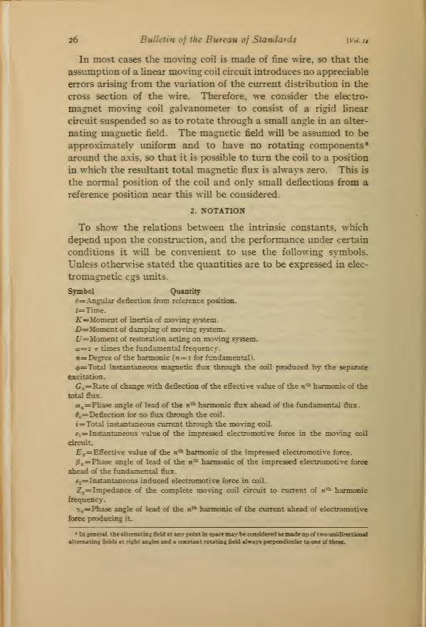
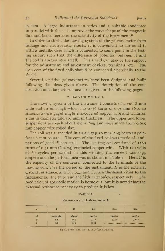
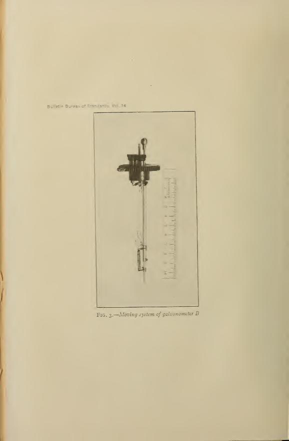
Fig. 3.
—
Mazing sysUm of gaUjuiomeier B

Weibel] Electromagnet Galvanometer 45
Approximate values of the intrinsic constants of this instrument
are as follows
:
K = 0.022, i^ =0.001, Z7 = 0.028, Gi = 28ooo, G2 = 28o, G^ = ^o, andr = I4X 10^.
3. GALVANOMETER B
This instrument was intended for use with apparatus in whichthe resistance between the terminals to which the galvanometer is
to be connected is of the order of 100 ohms. A period of only a
few seconds, a sensitivity of several millimeters per microvolt, andaperiodic motion were required so that it was necessary to use a
light coil. The coil consists of 100 turns of 0.08 mm (No. 40)
enamelled copper wire wound on a wood frame to make a coil 2
cm long, 0.3 cm wide, and o. i cm thick. The wire is insulated with
cellulose acetate which is very thin. The coil was treated with
potassium copper chloride to remove the magnetic impurities and
it was then washed, dried, and dipped into collodion, which boundthe parts firmly together. The two end wires of the coil are
brought out at the top instead of in the usual way in order not to
have a large portion of the total magnetic flux through the core
linking the moving coil circuit. One of these wires is soldered to a
large copper wire, fixed to the wood frame of the coil, and to which
a mirror 0.8 cm in diameter is attached. To the end of this large
copper wire is soldered the supporting suspension, a flat copper
strip similar to those used before. To the other end wire is soldered
another strip, v/hich is left loose and runs approximately parallel
to the supporting suspension 0.3 cm away. The complete moving
system is shown in Fig. 3. The fibre plug at the top fits into the
case of the instrument as shown in Fig. i . The moving system is
easily removed, to be replaced by another of different constants.
The coil swings in a gap 0.6 cm long in the laminated steel core
2 by 0.8 cm in section. There are two exciting coils each woundwith 650 turns of 0.72 mm (No. 21) enamelled copper wire, and the
coils are arranged for either series or parallel connection.
TABLE 2
PERFORMANCE OF GALVANOMETER B
f Excitation C T R s
^/second volts ampere i"i seconds ohms mm//Liv
2.6 0.4 0.00 1.7 25 2.3
3.9 .6 .00 1.4 60 1.2
60 29.0 .4 .00 1.9 30 2.6
60 29.0 .4 .22 4.2 100 5.7
46 Bulletin of the Bureau of Standards [Voi. u
The performance of this instrument under certain conditions of
use can be seen from Table 2. The intrinsic constants were found
to be as follows
:
/C =0.006, D =0.0009, L^=o.05 + o.2 / 2, G = 115 000 /,
r = 25 X 10® and c=o.07.
Here / is the exciting current in amperes (coils in series). Therestoring force is seen to depend upon the excitation showing that
there are magnetic impurities in the moving system. On account
of the thin insulation used the capacity between turns is large andthe quantity c is the capacity in microfarads which, if connected
to the terminals, would affect the period by an amount equal to
the effect of the distributed capacity. The resistance of the twofixed coils in series is 6.4 ohms and the inductance is 0.18 henry.
The insulation is such that 1 20 volts can be used for excitation.
4. GALVANOMETER C
The fixed system of this galvanometer is the same as that of
Galvanometer B. The moving system consists of a coil of 75
turns of 0.08 mm (No. 40) single silk-covered copper wire woimdto form a coil 2 cm long, 0.5 cm wide, and about 0.15 cm thick,
and a mirror 0.8 cm in diameter. This coil was made without
a form by winding the wire over two copper wires held parallel
and about 2 cm apart. It is necessary to remove the twist in the
wire before winding, otherwise the coil will warp when taken off
of the winding device. The turns of wire were bound together
by means of silk fibers. Small copper end pieces are attached to
hold the mirror and to serve as connections between the suspen-
sions. After these were attached the coil was treated as before to
remove the magnetic dirt and was then washed, dried, and dipped
in collodion. The coil is rigid enough for the purpose.
The performance of this instrument is very satisfactory, the
capacity effect being small and the coil being very free from mag-
netic impurities.'*^
In order to check the theory approximately the quantities K,
D, Uy and G were measured by the method already described.
This was done for various values of the exciting current and fre-
^ Alter first assembling this instrument its period with the field on was found to be much shorter than
without the field, showing the coil to be magnetic. It was assumed that this was due to magnetic dirt
picked up by the coil in the assembling. The coil was then treated again and replaced and the above results
obtained. The total change in the restoring force when this coil is placed in a field of 4000 gausses is 0.02
dyne cm per radian, which is strikingly small. For Galvanonaeter B the change is 0.2 dyne cm per radian
for the same field strength.
Weihel\ Electromagnet Galvanometer 47
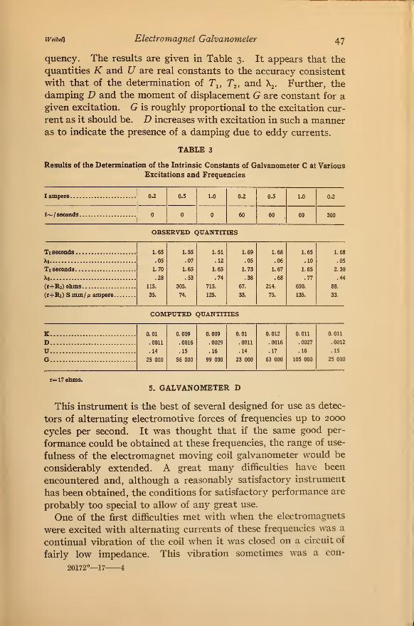
quency. The results are given in Table 3. It appears that the
quantities K and U are real constants to the accuracy consistent
with that of the determination of Tj, T^, and \. Further, the
damping D and the moment of displacement G are constant for a
given excitation. G is roughly proportional to the excitation cur-
rent as it should be. D increases with excitation in such a manneras to indicate the presence of a damping due to eddy currents.
TABLE 3
Results of the Determination of the Intrinsic Constants of Galvanometer C at Various
Excitations and Frequencies
I ampere 0.2 0.5 1.0 0.2 0.5 1.0 0.2
f~ / seconds 60 60 60 300
OBSERVED QUANTITIES
Ti seconds .
Xi
T2 seconds.
X2
(r+R2) ohms
(r+Ri) S mm//i ampere.
1.65 1.55 1.51 1.69 1.68 1.65
.05 .07 .12 .05 .06 .10
1.70 1.65 1.65 1.73 1.67 1.65
.28 .53 .74 .38 .68 .77
115. 305. 715. 67. 214. 650.
35. 74. 125. 33. 75. 135.
1.68
.05
2.30
.44
88.
33.
COMPUTED QUANTITIES
K 0.01
.0011
.14
25 000
0.009
.0016
.15
56 000
0.009
.0029
.16
99 000
0.01
.0011
.14
23 000
0.012
.0016
.17
63 000
0.011
.0027
.16
105 000
0.011
D .0012
U- .15
G 25 000
r= 17 ohms.
5. GALVANOMETER D
This instrument is the best of several designed for use as detec-
tors of alternating electromotive forces of frequencies up to 2000
cycles per second. It was thought that if the same good per-
formance could be obtained at these frequencies, the range of use-
fulness of the electromagnet moving coil galvanometer would be
considerably extended. A great many difficulties have been
encountered and, although a reasonably satisfactory instrument
has been obtained, the conditions for satisfactory performance are
probably too special to allow of any great use.
One of the first difficulties met with when the electromagnets
were excited with alternating currents of these frequencies was a
continual vibration of the coil when it was closed on a circuit of
fairly low impedance. This vibration sometimes was a con-
20172°—17 4
48 Bulletin of the Bureau of Standards [Vol.ii
Weak Field
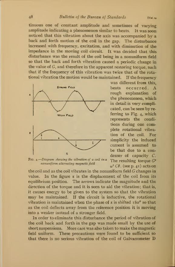
tinuous one of constant amplitude and sometimes of varyingamplitude indicating a phenomenon similar to beats. It was soonnoticed that this vibration about the axis was accompanied by aback and forth motion of the coil in the gap. The disturbance
increased with frequency, excitation, and with diminution of the
impedance in the moving coil circuit. It was decided that this
disturbance was the result of the coil being in a nonuniform field
so that the back and forth vibration caused a periodic change in
the value of G, and therefore in the apparent restoring torque, suchthat if the frequency of this vibration was twice that of the rota-
tional vibration the motion would be maintained. If the frequency
was different from this,
Stbomo r.cLo beats occurred. Arough explanation of
the phenomenon, which
in detail is very compli-
cated, can be seen by re-
ferring to Fig. 4, which
represents the condi-
tions during one com-
plete rotational vibra-
tion of the coil. For
simplicity the induced
current is assumed to
be that due to a con-
denser of capacity C.
The resulting torque G^
co^Cd. (see p. 41) acts on
the coil and as the coil vibrates in the nonuniform field G changes in
value. In the figvire x is the displacement of the coil from its
equilibrium position. The arrows indicate the magnitude and the
direction of the torque and it is seen to aid the vibration; that is,
it causes energy to be given to the system so that the vibration
may be maintained. If the circuit is inductive, the rotational
vibration is maintained when the phase of x is shifted 1 80° so that
as the coil deflects away from the reference position it is moving
into a weaker instead of a stronger field.
In order to eliminate this disturbance the period of vibration of
the coil back and forth in the gap was made small by the use of
short suspensions. More care was also taken to make the magnetic
field uniform. These precautions were found to be sufficient so
that there is no serious vibration of the coil of Galvanometer D
Fig. 4.
—
Diagram showing the vihraiion of a coil in a
nonunifonn alternating magnetic field
Weibei] Electromagnet Galvanometer 49
at 2IOO cycles per second even when the moving coil circuit is veryinductive.
Referring to equation (14) we see that as the frequency is
increased the term
—y- sm 7
increases if 7 is not zero so that there is a change in the total
restoring torque and in the rest point. In order to obtain satis-
factory performance this effect must be kept small so that it is
necessary to keep 7 small. At low frequencies the inductancecan be compensated for by the use of a series resistance in parallel
with a condenser as explained above. This compensation canbe made to hold for a fairly large range of frequencies but at
the higher frequencies such is not the case if the resistance is to
be kept reasonably low. The frequency must therefore be main-tained constant for satisfactory operation.
In the design of an alternating-current electromagnet for use
as a frequency of 2000 cycles per second the losses due to hysteresis
and eddy currents have to be considered. Since an air gap is
necessary in which to swing the coil, there is considerable leakage
so that the magnetic induction in the core may be several times
the field strength required in the gap. It was found by the
measurements of the apparent resistance and inductance ^^ of
iron-cored coils that the losses could be computed with sufficient
certainty from data obtained at low frequencies.
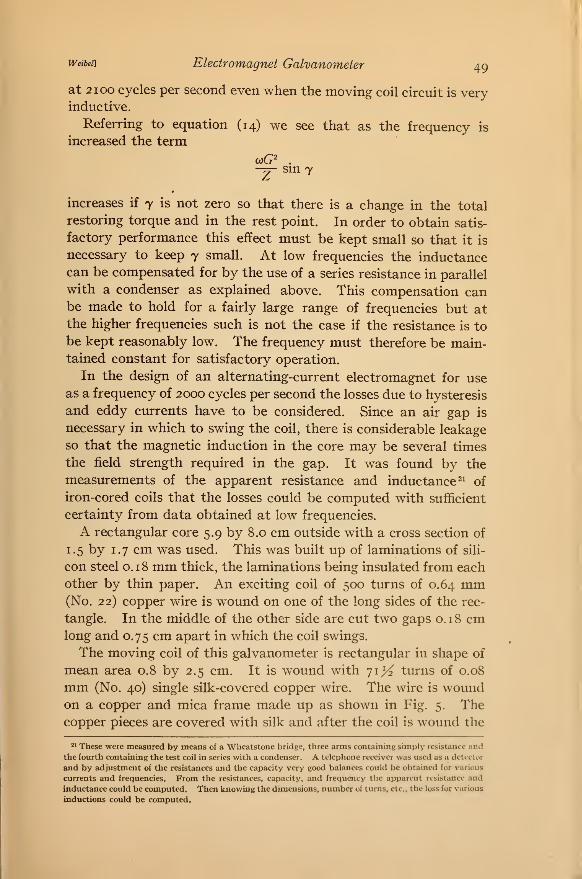
A rectangular core 5.9 by 8.0 cm outside with a cross section of
1.5 by 1.7 cm was used. This was built up of laminations of sili-
con steel 0.18 mm thick, the laminations being insulated from each
other by thin paper. An exciting coil of 500 turns of 0.64 mm(No. 22) copper wire is wound on one of the long sides of the rec-
tangle. In the middle of the other side are cut two gaps o. 1 8 cmlong and 0.75 cm apart in which the coil swings.
The moving coil of this galvanometer is rectangular in shape of
mean area 0.8 by 2.5 cm. It is wound with 71X turns of 0.08
mm (No. 40) single silk-covered copper wire. The wire is woundon a copper and mica frame made up as shown in Fig. 5. Thecopper pieces are covered with silk and after the coil is wound the
21 These were measured by means of a Whcatstone bridge, three arms containing simply resistance and
the fourth containing the test coil in series with a condenser. A telephone receiver was used as u detector
and by adjustment of the resistances and the capacity very good balances could be obtained for various
currents and frequencies. From the resistances, capacity, and frequency the apparent resistance and
inductance could be computed. Then knowing the dimensions, number of turns, etc., the loss for various
inductions could be computed.
50 Bulletin of the Bureau of Standards [Vol. 14
small copper extensions are bent down and hold the wire in place.
The mirror is attached as shown. The suspensions of this instru-
ment are about i cm long and are of the flat copper strip used
before. The lower suspension is soldered
to a small flat copper spring so that the
suspensions can be held tight.
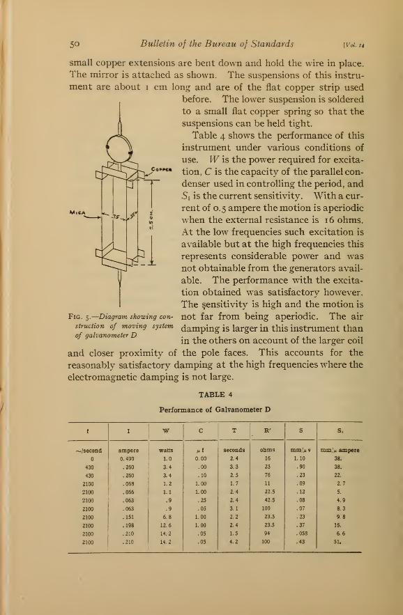
Table 4 shows the performance of this
instrument under various conditions of
use. W is the power required for excita-
tion, C is the capacity of the parallel con-
denser used in controlling the period, and
5i is the current sensitivity. With a cur-
rent of 0.5 ampere the motion is aperiodic
when the external resistance is 16 ohms.
At the low frequencies such excitation is
available but at the high frequencies this
represents considerable power and was
not obtainable from the generators avail-
able. The performance with the excita-
tion obtained was satisfactory however.
The sensitivity is high and the motion is
not far from being aperiodic. The air
damping is larger in this instrument than
in the others on account of the larger coil
and closer proximity of the pole faces. This accounts for the
reasonably satisfactory damping at the high frequencies where the
electromagnetic damping is not large.
Fig. 5.
—
Diagram showing con-
struction of moving system
of galvanometer D
TABLE 4
Performance of Galvanometer D
i I W C T R' S s>
~/second ampere watts nt seconds Ohms mm/M V mm;> ampere
0.490 1.0 0.00 2.4 16 1.10 38.
430 .260 3.4 .00 3.3 23 .90 38.
430 .260 3.4 .10 2.5 76 .23 22.
2100 .068 1.2 1.00 1.7 11 .09 2.7
2100 .066 1.1 1.00 2.4 22.5 .12 5.
2100 .063 .9 .25 2.4 42.5 .08 4.9
2100 .063 .9 .05 3.1 100 .07 8.3
2100 .151 6.8 1.00 2.2 23.5 .23 9.8
2100 .198 12.6 1.00 2.4 23.5 .37 16.
2100 .210 14.2 .05 1.5 94 .058 6.6
2100 .210 14.2 .05 4.2 100 .43 51.
weibdi Electromagnet Galvanometer 51
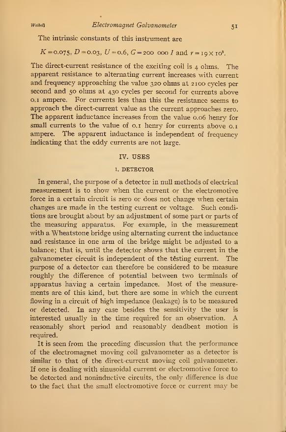
The intrinsic constants of this instrument are
K = o.oys, 17=0.03, U = o.6, G = 2oo 000 / and r = igx lo^
The direct-current resistance of the exciting coil is 4 ohms. Theapparent resistance to alternating current increases with current
and frequency approaching the value 320 ohms at 2100 cycles persecond and 50 ohms at 430 cycles per second for currents above0.1 ampere. For currents less than this the resistance seems to
approach the direct-current value as the current approaches zero.
The apparent inductance increases from the value 0.06 henry for
small currents to the value of o.i henry for currents above o.i
ampere. The apparent inductance is independent of frequency
indicating that the eddy currents are not large.
IV. USES
1. DETECTOR
In general, the purpose of a detector in null methods of electrical
measurement is to show when the current or the electromotive
force in a certain circuit is zero or does not change when certain
changes are made in the testing current or voltage. Such condi-
tions are brought about by an adjustment of some part or parts of
the measuring apparatus. For example, in the measurementwith a Wheatstone bridge using alternating current the inductance
and resistance in one arm of the bridge might be adjusted to a
balance; that is, until the detector shows that the current in the
galvanometer circuit is independent of the testing current. Thepurpose of a detector can therefore be considered to be measure
roughly the difference of potential between two terminals of
apparatus having a certain impedance. Most of the measure-
ments are of this kind, but there are some in which the current
flowing in a circuit of high impedance (leakage) is to be measured
or detected. In any case besides the sensitivity the user is
interested usually in the time required for an observation. Areasonably short period and reasonably deadbeat motion is
required.
It is seen from the preceding discussion that the performance
of the electromagnet moving coil galvanometer as a detector is
similar to that of the direct-current moving coil galvanometer.
If one is dealing with sinusoidal current or electromotive force to
be detected and noninductive circuits, the only difference is due
to the fact that the small electromotive force or current may be
52 Bulletin of the Bureau of Standards [voi. 14
out of phase with the magnetic field. Since the deflection is
proportional to the component of the electromotive force in phase
with the magnetic field, zero deflection means only that the
electromotive force, if it is detectable, is in quadrature with the
magnetic field. In order, therefore, to be sure that the electro-
motive force is zero, the phase of the excitation is changed. Withnoninductive circuits the phase of the excitation can be adjusted
once for all so that the maximum sensitivity is obtained. Underthese conditions the magnetic field is in phase with the unbal-
anced electromotive forces which are always in the same phase.
However, in this case, it is only necessary that the magnetic field
be approximately in phase with the testing current, for since the
phase of the unbalanced electromotive forces is always the same as
that of the testing current, only its magnitude can be changed andhence zero deflection means zero electromotive force..
Usually in alternating-current measurements w^e have to do with
apparatus having both resistance and reactance so that the un-
balanced electromotive force may be of any phase whatsoever.
There are usually two adjustments, the "resistance" and the
"inductance" adjustments. A small change in one results in a
change in the unbalanced electromotive force with a phase approx-
imately in quadrature with the change produced by the other
adjustment. Now if the phase of the excitation be such that a
large change in one adjustment produces no change in deflection,
it is possible by shifting the phase of the excitation 90 electrical
time degrees to make the one adjustment independent of the
other. When such an adjustment of the phase of the magnetic
field is not made the balance must be obtained by successive
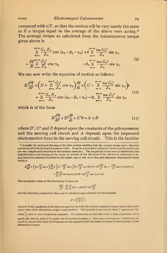
approximations. This is illustrated in Fig. 6. Here 4)^ and 02
are the two phase positions of the magnetic field, R and L are the
phases of the resistance and inductance adjustments, respectively,
and E is the small electromotive force to be reduced to zero.
Suppose to start with, the excitation is at 0i we w^ill now makesome adjustment which reduces the deflection to zero; that is,
makes E in quadrature with </>!. To do. this we may make either
a resistance or an inductance adjustment. Suppose, first, wemake an inductance adjustment which carries the end of E to a.
Now shift the excitation to 02 ^^^ make a resistance adjustment
which brings us to 5, and so on. After a number of adjustments
the deflection will be reduced to a negligible amount for both
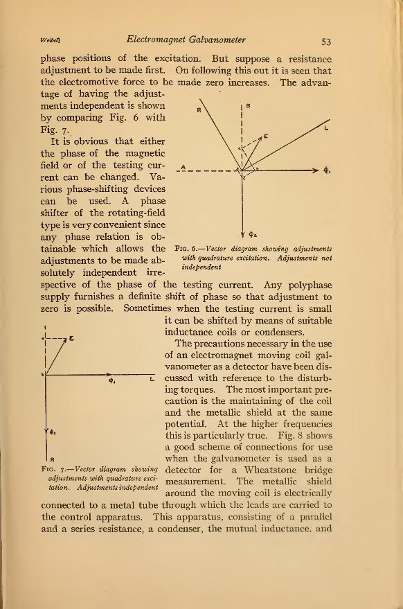
Weibet\ Electromagnet Galvanometer 53
Fig. 6.
—
Vector diagram showing adjustments
with quadrature excitation. Adjustments not
independent
phase positions of the excitation. But suppose a resistance
adjustment to be made first. On following this out it is seen that
the electromotive force to be made zero increases. The advan-
tage of having the adjust-
ments independent is shown
by comparing Fig. 6 with
Fig. 7..
It is obvious that either
the phase of the magnetic
field or of the testing cur-
rent can be changed. Va-
rious phase-shifting devices
can be used. A phase
shifter of the rotating-field
type is very convenient since
any phase relation is ob-
tainable which allows the
adjustments to be made ab-
solutely independent irre-
spective of the phase of the testing current. Any polyphase
supply furnishes a definite shift of phase so that adjustment to
zero is possible. Sometimes when the testing current is small
it can be shifted by means of suitable
inductance coils or condensers.
The precautions necessary in the use
of an electromagnet moving coil gal-
vanometer as a detector have been dis-
cussed with reference to the disturb-
ing torques. The most important pre-
caution is the maintaining of the coil
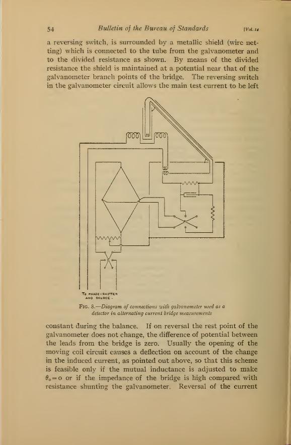
and the metallic shield at the samepotential. At the higher frequencies
this is particularly true. Fig. 8 shows
a good scheme of connections for use
when the galvanometer is used as a
detector for a Wheatstone bridge
measurement. The metallic shield
around the moving coil is electrically
connected to a metal tube through which the leads are carried to
the control apparatus. This apparatus, consisting of a parallel
and a series resistance, a condenser, the mutual inductance, and
^»
^^a
R
Fig. 7.
—
Vector diagram showing
adjustments with quadrature exci-
tation. Adjustments independent
54 Bulletin of the Bureau of Standards [Vol. 14
a reversing switch, is surrounded by a metallic shield (wire net-
ting) which is connected to the tube from the galvanometer andto the divided resistance as shown. By means of the divided
resistance the shield is maintained at a potential near that of the
galvanometer branch points of the bridge. The reversing switch
in the galvanometer circuit allows the main test current to be left
To »»HASE-SMirTEBAND SOURCE .
Fig. 8.
—
Diagram of connections uith galvanometer used as a
detector in alternating current bridge measurements
constant during the balance. If on reversal the rest point of the
galvanometer does not change, the difference of potential between
the leads from the bridge is zero. Usually the opening of the
moving coil circuit causes a deflection on account of the change
in the induced current, as pointed out above, so that this scheme
is feasible only if the mutual inductance is adjusted to make
^o = o or if the impedance of the bridge is high compared with
resistance shunting the galvanometer. Reversal of the current
Tl
Weibet\ Electromagnet Galvanometer 55
is the most desirable method of testing for a balance, for then theimpedance of the moving coil circuit remains constant and apermanent change in deflection can result only from an electro-
motive force which reverses when the test current is reversed.
In case the balance depends upon the frequency, reversal maycause a sudden motion of the coil due to the differences in the rates
of decay and growth of the currents furnishing the balancing
electromotive forces. Care is also necessary if stray electric or
magnetic fields are present.
In some measurements it is desirable that the detector besensitive to currents of the fundamental frequency only. This
is the case when sinusoidal supply is not available or when har-
monics are introduced by the apparatus so that the compara-tively large harmonic electromotive forces must not cause deflec-
tions which will mask the deflection produced by the fundamental
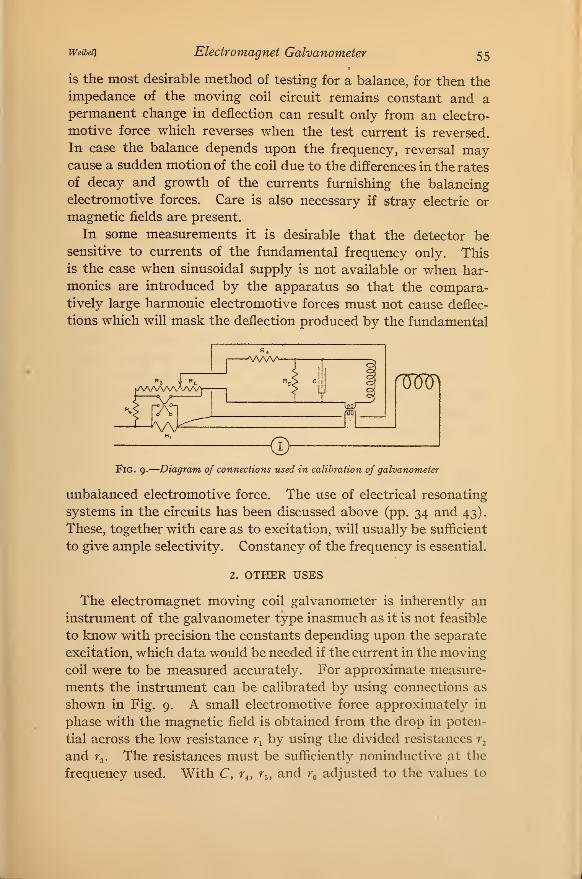
Fig. 9.
—
Diagram of connections used in calibration of galvanometer
unbalanced electromotive force. The use of electrical resonating
systems in the circuits has been discussed above (pp. 34 and 43).
These, together with care as to excitation, will usually be sufficient
to give ample selectivity. Constancy of the frequency is essential.
2. OTHER USES
The electromagnet moving coil galvanometer is inherently an
instrument of the galvanometer type inasmuch as it is not feasible
to know with precision the constants depending upon the separate
excitation, which data would be needed if the current in the moving
coil were to be measured accurately. For approximate measure-
ments the instrument can be calibrated by using connections as
shown in Fig. 9. A small electromotive force approximately in
phase with the magnetic field is obtained from the drop in poten-
tial across the low resistance r^ by using the divided resistances r^
and ^3. The resistances must be sufficiently noninductive at the
frequency used. With C, r^, fj, and r^ adjusted to the values to
56 BtUletin of the Bureau of Standards [Voi. u
be used in the measurement the change in the deflection on re-
versing the electromotive force is noted. A simple calculation
then gives the calibration factor. The resistance r^ is very high
in comparison with r^ and is used to maintain the resistances rj and
fs and hence the moving coil circuit at the potential of the shield
when the switch is open. This is very necessar}^ at high frequen-
cies on account of the capacity current which would flow through
the moving coil due to the capacity betw^een the resistances r, and
fa and the surroundings. If the apparatus containing the small
electromotive force to be measured is available it should be in-
serted so that the moving coil circuit will be the same during the
calibration as during the measurement.
The electromagnet moving coil galvanometer can be used to
measure inductance in terms of capacity and vice versa by a
resonance method in which the inductance and capacity are in-
serted in series in the moving coil circuit. For this measurement
the moving coil is displaced from its position of zero induced elec-
tromotive force so that ^o = o. Now suppose that either the in-
ductance or the capacity be adjusted until there is no deflection
on closing the circuit. Then if the excitation be sinusoidal wemust have from (i i)
sin 7
which means that
= o (60)
^-i- (6')
The sensitivity is determined by ^o, G, and the magnitude of
the series resistance R' and from (11) can be shown to be deter-
mined by the equation
By referring to the data on the instruments it is seen that a
difference corresponding to i microhenry can be detected at 60
cycles per second. Therefore we see that a small reactance can
be measured by itself, and equation (62) shows that the deflection
is proportional to the reactance and is in one direction if it is
inductive and is in the other if it is condensive reactance.
This study is part of a general investigation of galvanometers
being carried on by Dr. Frank Wenner and the author, and the
experience gained in the study of sensitive permanent magnet
Weibei] Electvomagnet Galvanometer 57
moving coil galvanometers for direct current has been especially
valuable. I am much indebted to Dr. Wenner for his hearty
cooperation in this work.
V. SUMMARY
(i) The electromagnet moving coil galvanometer has been
studied and the equation of motion obtained, from which its per-
formance under various conditions can be determined. The per-
formance as a detector is very similar to that of the direct-current
moving coil galvanometer in that the motion of the coil may,in general, be of any degree of damping, depending upon the ex-
ternal circuit and in that the deflection is proportional to the im-
pressed electromotive force. In the electromagnet moving coil
galvanometer the period, as well as the damping, depends uponthe constants of the external circuit being shortened by inductance
and lengthened by capacity. Further, the deflection produced
depends upon the component of the electromotive force in phase
with the excitation.
(2) The relations between the operating and the intrinsic con-
stants are given, so that the design and construction of instru-
ments for any particular purpose are facilitated.
(3) A method of determining the intrinsic constants of electro-
magnet moving coil galvanometers has been devised. This gives
from observations on the performance, under easily obtained work-
ing conditions, the moment of inertia, moment of damping,
moment of restoration, etc., so that the performance of the instru-
ment under other conditions can be predicted.
(4) An analysis of the disturbances has been made and it has
been shown that the best procedure in the use of a sensitive elec-
tromagnet moving coil galvanometer is to surround the moving
coil and moving coil circuit up to the testing apparatus by a
metallic shield, which is maintained at a potential equal to that
of the moving coil circuit. This can be done by connecting the
shield to a point on the testing circuit having the same potential
as the moving coil.
(5) The description and performance of four sensitive instru-
ments are given and show results as expected from the theory.
The sensitivity of these instruments is much greater than that of
the telephone receiver at the lower frequencies. It is greater
than that of the vibration galvanometer and is equal to that of
the best direct-current moving coil galvanometers. The instru-
58 Bulletin of the Bureau of Standards [Voi. 14
ments have been found to give very satisfactory performance at
low frequencies. One instrument has been used at the frequency
of 2100 cycles per second and, although very sensitive, many pre-
cautions have to be taken for satisfactory operation.
Washington, April 4, 191 6.
'/