A study for production simulation model generation system ...
15
A study for production simulation model generation system based on data model at a shipyard Myung-Gi Back a , Dong-Kun Lee b , Jong-Gye Shin a,c , Jong-Hoon Woo d, * a Dept. of Naval Architecture and Ocean Engineering, Seoul National University, Seoul, South Korea b Dept. of Naval Architecture and Ocean Engineering, Mokpo National Maritime University, Mokpo, South Korea c Research Institute of Marine Systems Engineering, Seoul National University, Seoul, South Korea d Dept. of Naval Architecture and Ocean Systems Engineering, Korea Maritime and Ocean University, Busan, South Korea Received 30 June 2015; revised 15 March 2016; accepted 2 May 2016 Available online 22 July 2016 Abstract Simulation technology is a type of shipbuilding product lifecycle management solution used to support production planning or decision- making. Normally , most shipbuilding processes are consisted of job shop production, and the modeling and simulation require professional skills and experience on shipbuilding. For these reasons, many shipbuilding companies have difficulties adapting simulation systems, regardless of the necessity for the technology . In this paper, the data model for shipyard production simulation model generation was defined by analyzing the iterative simulation modeling procedure. The shipyard production simulation data model defined in this study contains the information necessary for the conventional simulation modeling procedure and can serve as a basis for simulation model generation. The efficacy of the developed system was validated by applying it to the simulation model generation of the panel block production line. By implementing the initial simulation model generation process, which was performed in the past with a simulation modeler, the proposed system substantially reduced the modeling time. In addition, by reducing the difficulties posed by different modeler-dependent generation methods, the proposed system makes the standardization of the simulation model quality possible. Copyright © 2016 Society of Naval Architects of Korea. Production and hosting by Elsevier B.V. This is an open access article under the CC BY-NC-ND license (http://creativecommons.org/licenses/by-nc-nd/4.0/). Keywords: Modeling and simulation; Digital shipbuilding system; Simulation model generation; Shipyard data model; Panel block assembly shop; Shipbuilding 1. Introduction Today' s shipbuilding industry is facing a serious deprecia- tion as a result of being severely affected by the current global economic recession. Because of low ship prices, small-and- medium shipbuilding companies are experiencing liquidity crises, and even large shipbuilding companies are threatened by the competition from emerging shipbuilding countries. To counteract these situations, many shipbuilders are turning their attention to high value-added lines, such as offshore plants or drill ships. They are increasingly upgrading their operation capacities from the traditional management system with commercial vessel-centered structures and databases to a system that prioritizes the development of new high value- added vessel types. In particular, shipbuilders are placing their effort into establishing a strategically efficient production system that integrates new production technology with the Advanced Planning System (APS) and the Manufacturing Execution System (MES) (Song et al., 2011). This paper presents a method for the simple and systematic application of modeling and simulation that has been attract- ing attention as a new production support system. Extensive research has been conducted on manufacturing simulation designed to set up plans with high accurate capable of pre- dicting imminent production-related problems (Woo et al., 2009; Wang et al., 2009). Considering the simulation of the * Corresponding author. E-mail address: [email protected] (J.-H. Woo). Peer review under responsibility of Society of Naval Architects of Korea. Available online at www.sciencedirect.com ScienceDirect Publishing Services by Elsevier International Journal of Naval Architecture and Ocean Engineering 8 (2016) 496e510 http://www.journals.elsevier.com/international-journal-of-naval-architecture-and-ocean-engineering/ http://dx.doi.org/10.1016/j.ijnaoe.2016.05.005 2092-6782/Copyright © 2016 Society of Naval Architects of Korea. Production and hosting by Elsevier B.V. This is an open access article under the CC BY-NC-ND license (http://creativecommons.org/licenses/by-nc-nd/4.0/).
Transcript of A study for production simulation model generation system ...

Available online at www.sciencedirect.com
ScienceDirectPublishing Services by Elsevier
International Journal of Naval Architecture and Ocean Engineering 8 (2016) 496e510http://www.journals.elsevier.com/international-journal-of-naval-architecture-and-ocean-engineering/
A study for production simulation model generation system based on datamodel at a shipyard
Myung-Gi Back a, Dong-Kun Lee b, Jong-Gye Shin a,c, Jong-Hoon Woo d,*a Dept. of Naval Architecture and Ocean Engineering, Seoul National University, Seoul, South Korea
b Dept. of Naval Architecture and Ocean Engineering, Mokpo National Maritime University, Mokpo, South Koreac Research Institute of Marine Systems Engineering, Seoul National University, Seoul, South Korea
d Dept. of Naval Architecture and Ocean Systems Engineering, Korea Maritime and Ocean University, Busan, South Korea
Received 30 June 2015; revised 15 March 2016; accepted 2 May 2016
Available online 22 July 2016
Abstract
Simulation technology is a type of shipbuilding product lifecycle management solution used to support production planning or decision-making. Normally, most shipbuilding processes are consisted of job shop production, and the modeling and simulation require professional skillsand experience on shipbuilding. For these reasons, many shipbuilding companies have difficulties adapting simulation systems, regardless of thenecessity for the technology. In this paper, the data model for shipyard production simulation model generation was defined by analyzing theiterative simulation modeling procedure. The shipyard production simulation data model defined in this study contains the information necessaryfor the conventional simulation modeling procedure and can serve as a basis for simulation model generation. The efficacy of the developedsystem was validated by applying it to the simulation model generation of the panel block production line. By implementing the initialsimulation model generation process, which was performed in the past with a simulation modeler, the proposed system substantially reduced themodeling time. In addition, by reducing the difficulties posed by different modeler-dependent generation methods, the proposed system makesthe standardization of the simulation model quality possible.Copyright © 2016 Society of Naval Architects of Korea. Production and hosting by Elsevier B.V. This is an open access article under theCC BY-NC-ND license (http://creativecommons.org/licenses/by-nc-nd/4.0/).
Keywords: Modeling and simulation; Digital shipbuilding system; Simulation model generation; Shipyard data model; Panel block assembly shop; Shipbuilding
1. Introduction
Today's shipbuilding industry is facing a serious deprecia-tion as a result of being severely affected by the current globaleconomic recession. Because of low ship prices, small-and-medium shipbuilding companies are experiencing liquiditycrises, and even large shipbuilding companies are threatenedby the competition from emerging shipbuilding countries. Tocounteract these situations, many shipbuilders are turning theirattention to high value-added lines, such as offshore plants ordrill ships. They are increasingly upgrading their operation
* Corresponding author.
E-mail address: [email protected] (J.-H. Woo).
Peer review under responsibility of Society of Naval Architects of Korea.
http://dx.doi.org/10.1016/j.ijnaoe.2016.05.005
2092-6782/Copyright© 2016 Society of Naval Architects of Korea. Production and
license (http://creativecommons.org/licenses/by-nc-nd/4.0/).
capacities from the traditional management system withcommercial vessel-centered structures and databases to asystem that prioritizes the development of new high value-added vessel types. In particular, shipbuilders are placingtheir effort into establishing a strategically efficient productionsystem that integrates new production technology with theAdvanced Planning System (APS) and the ManufacturingExecution System (MES) (Song et al., 2011).
This paper presents a method for the simple and systematicapplication of modeling and simulation that has been attract-ing attention as a new production support system. Extensiveresearch has been conducted on manufacturing simulationdesigned to set up plans with high accurate capable of pre-dicting imminent production-related problems (Woo et al.,2009; Wang et al., 2009). Considering the simulation of the
hosting by Elsevier B.V. This is an open access article under the CC BY-NC-ND

497M.-G. Back et al. / International Journal of Naval Architecture and Ocean Engineering 8 (2016) 496e510
evaluation of the shipyard panel line capacity as an example,shipbuilding expert analysis of the target factory or line isrequired, followed by long-term modeling by a specializedsimulation modeler. Sophisticated modeling should be per-formed by a modeler with corresponding background andexperience. Because most shipbuilding companies do not haveadequate human resources, modeling projects are usuallyimplemented by modeling specialists based on commission.Against this background, this study is intended to develop andpresent an automated simulation model by redefining theshipbuilding-related data from the simulation perspective, anddeveloping a system based on the data obtained thus far.
For the development of an automated simulation modelingtechnology, three structural components should be established:a data model with definitions based on the shipbuilding data,simulation control scripts for simulation modeling, and aninterface system for simulation software monitoring. Researchinto simulation automation techniques began in the 2000s withthe National Institute of Standards and Technology (NIST) asthe leading institute. A variety of practical studies have beenreported ever since. Lu et al. (2003) proposed a simulationinterface specification for automatic factory modeling for theaircraft manufacturer Boeing. Harward and Harrell (2006)created a neutral file for simulation based on the NIST shopdata model and validated its efficacy. More recently, with thedevelopment of the neutral simulation schema (NESIS), whichintegrates related systems by analyzing a range of simulationsoftware architectures and previous studies on simulation datamodels for the assembly line production industry, a web-basedmodel exchange service was presented (Lee et al., 2011a). Apractical interoperability technology that offers integration ofheterogeneous software components was implemented using asimulation data model, thus verifying the efficacy of thesimulation data model.
Fig. 1 presents the NESIS simulation data model where thedata required for simulation are structured in an integrated systemthat consists of three model elements, namely: a) product, pro-cess, and resource, b) configuration for simulation model envi-ronment setting, and c) Sim_List structured based on the routingdata of the model elements. In this model architecture, thestructure for the product, process, and resource is the part that canexpress the simulation software data in sharable formats, thus
Fig. 1. Simulation data model schema for NESIS (Lee et al., 2011b).
posing no difficulties for general factory simulation. Thespecialized routing expression part is addressed by the Sim_Liststructure. However, in the shipbuilding industry that constitutesthe research object of this study, job shop type processes typicallyoccupy the bulk of the entire operation, and schedule-related dataoccupy a largeproportionof the system.This particularity and thehigh number of resources that influence the process steps act aslimitations for expressing the shipbuilding process simulationwith the NESIS architecture. To overcome this difficulty, thispaper explores a NESIS-based improved simulation data modelthat considers the product, process, layout, facility, labor, andscheduled data, specific to the shipbuilding production system.Subsequently, a case study is conducted in a field situation tovalidate the data model and test the application method.
2. Background of automation technology for shipbuildingsimulation modeling
In most cases, the simulation for product development ordesign is embedded in the corresponding Computer AidedDesign (CAD) tool as a module. Correspondingly, the simu-lation does not require an additional module for data conver-sion, mapping, or system control, unless a separate simulationtool is employed. However, in the case of production simu-lation, such simulation should run based on data other thanproduct information, such as information on equipment, re-sources, and production and project schedule (Watson et al.,1997). To address this limitation through the application ofthe simulation technology to a shipyard field situation, Songet al. (2009) established a simulation model that supportsdetection in advance and solution of the problems likely tooccur in a block assembly factory. However, problems arose inthe process of field application of the relevant technology bythe field manager after learning the necessary technique,merely because the application of such technique greatly de-pends on the skills of the simulation modeling engineer. Thisexperience made it clear that a simple “foolproof” applicationmethod should be developed so that even a manager withoutsufficient knowledge of simulation technology can create andmanage simulation models.
Woo (2005) defined the simulation model generation proce-dure in three major steps, as shown in Fig. 2, while conducting astudy on the simulation methodology for the prediction of ship-yard productivity. In step 1, the problem to be identified or solvedis formulated, the systemgeneration project plan is set up, and thesystem goal is defined. In step 2, input data necessary for thesimulationmodel generation is collected, the collected input dataare analyzed to allow the definition of the data for the simulation,and the simulationmodel is specified based on the analyzed data.In step 3, the simulation model is implemented for productivityprediction, followed by validation and verification. Informationpertaining to the simulation goal defined in step 1 is extracted byapplying the simulation model constructed. A simulation modelis generated by following this series of processes and sub pro-cesses. In consideration of the time requirements, although thetime required in step 1 for formulating the problem and definingthe goal of the simulationmodel generation is inevitable, the time
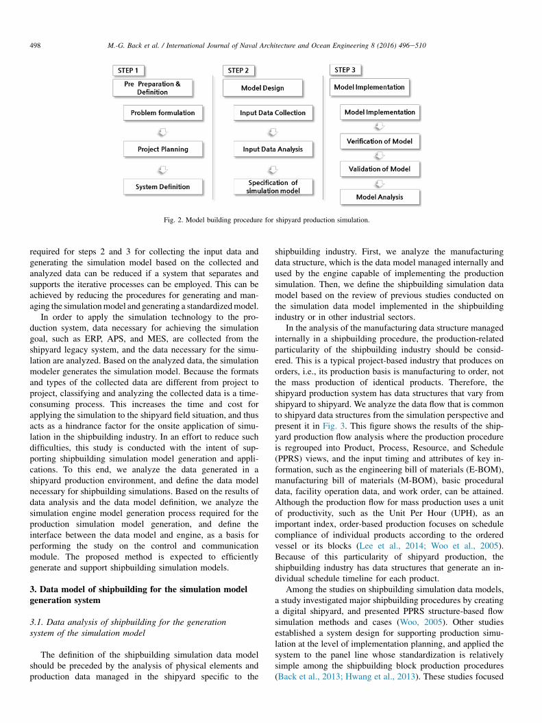
Fig. 2. Model building procedure for shipyard production simulation.
498 M.-G. Back et al. / International Journal of Naval Architecture and Ocean Engineering 8 (2016) 496e510
required for steps 2 and 3 for collecting the input data andgenerating the simulation model based on the collected andanalyzed data can be reduced if a system that separates andsupports the iterative processes can be employed. This can beachieved by reducing the procedures for generating and man-aging the simulationmodel and generating a standardizedmodel.
In order to apply the simulation technology to the pro-duction system, data necessary for achieving the simulationgoal, such as ERP, APS, and MES, are collected from theshipyard legacy system, and the data necessary for the simu-lation are analyzed. Based on the analyzed data, the simulationmodeler generates the simulation model. Because the formatsand types of the collected data are different from project toproject, classifying and analyzing the collected data is a time-consuming process. This increases the time and cost forapplying the simulation to the shipyard field situation, and thusacts as a hindrance factor for the onsite application of simu-lation in the shipbuilding industry. In an effort to reduce suchdifficulties, this study is conducted with the intent of sup-porting shipbuilding simulation model generation and appli-cations. To this end, we analyze the data generated in ashipyard production environment, and define the data modelnecessary for shipbuilding simulations. Based on the results ofdata analysis and the data model definition, we analyze thesimulation engine model generation process required for theproduction simulation model generation, and define theinterface between the data model and engine, as a basis forperforming the study on the control and communicationmodule. The proposed method is expected to efficientlygenerate and support shipbuilding simulation models.
3. Data model of shipbuilding for the simulation modelgeneration system
3.1. Data analysis of shipbuilding for the generationsystem of the simulation model
The definition of the shipbuilding simulation data modelshould be preceded by the analysis of physical elements andproduction data managed in the shipyard specific to the
shipbuilding industry. First, we analyze the manufacturingdata structure, which is the data model managed internally andused by the engine capable of implementing the productionsimulation. Then, we define the shipbuilding simulation datamodel based on the review of previous studies conducted onthe simulation data model implemented in the shipbuildingindustry or in other industrial sectors.
In the analysis of the manufacturing data structure managedinternally in a shipbuilding procedure, the production-relatedparticularity of the shipbuilding industry should be consid-ered. This is a typical project-based industry that produces onorders, i.e., its production basis is manufacturing to order, notthe mass production of identical products. Therefore, theshipyard production system has data structures that vary fromshipyard to shipyard. We analyze the data flow that is commonto shipyard data structures from the simulation perspective andpresent it in Fig. 3. This figure shows the results of the ship-yard production flow analysis where the production procedureis regrouped into Product, Process, Resource, and Schedule(PPRS) views, and the input timing and attributes of key in-formation, such as the engineering bill of materials (E-BOM),manufacturing bill of materials (M-BOM), basic proceduraldata, facility operation data, and work order, can be attained.Although the production flow for mass production uses a unitof productivity, such as the Unit Per Hour (UPH), as animportant index, order-based production focuses on schedulecompliance of individual products according to the orderedvessel or its blocks (Lee et al., 2014; Woo et al., 2005).Because of this particularity of shipyard production, theshipbuilding industry has data structures that generate an in-dividual schedule timeline for each product.
Among the studies on shipbuilding simulation data models,a study investigated major shipbuilding procedures by creatinga digital shipyard, and presented PPRS structure-based flowsimulation methods and cases (Woo, 2005). Other studiesestablished a system design for supporting production simu-lation at the level of implementation planning, and applied thesystem to the panel line whose standardization is relativelysimple among the shipbuilding block production procedures(Back et al., 2013; Hwang et al., 2013). These studies focused

Fig. 3. Production information flow of shipyard.
499M.-G. Back et al. / International Journal of Naval Architecture and Ocean Engineering 8 (2016) 496e510
on verifying production simulation cases and efficacies, thuseliciting the limitations in specifying production simulationdata models. Lee et al. (2013) conducted an extensible markuplanguage (XML)-based expandable simulation data model, butshowed limitations in reflecting the data that is essential forsimulation model generation and management. In the case ofother industries, studies on simulation data models have beenconducted under the NIST, for example, simulation data ex-change (SDX) allows data exchange among heterogeneoussimulation engines and data exchange interfaces (Sly andMoorthy, 2001; Johansson et al., 2007; Lee et al., 2011b;Kang, 2007). These studies were intended to allow simula-tion model exchange, and thus focused on the data on thesimulation itself rather than the object of the simulationapplication. Moreover, their data models revolved around re-sources suitable for flow production modeling, and thus havelimitations in their applications to the process-centered ship-building industry.
We defined the data model structure outline for the ship-building simulation based on the shipbuilding data model andgeneral simulation models. As illustrated in Fig. 4, the entiredata structure is regrouped into four major PPRS groups, andgroup sub data are specified up to seven step levels. Theproduct view schematically defines the product structure,
including product data. By dividing the product structure intoengineering and production domains, according to the ship-building feature of equal emphasis on the basic technicaldesign and production design, independent archiving andmanagement of the design and production data is ensured.Process view contains the process and production plan data,thus separately reflecting the process characterized by standardinformation, and the production characterized by actualworking information. The schedule view comprises the samestructure as the process view in consideration of its relation-ship with the production plan because it should contain thedate assigned to the corresponding working unit. The resourceview is segmented into jug necessary for actual work opera-tion, the resource plan that includes the transporter, and theshipyard plan for shipyard space composition.
3.2. Data model and database for the simulation modelgeneration system
In this study, data analysis for simulation modeling wasperformed from the PPRS views, as shown in Fig. 4, based onthe analysis results for E-BOM for shipyard design, M-BOMfor production, procedural data for work management, andwork assignment process that considers schedules and degrees

Fig. 4. Production simulation data model structure of shipyard from PPRS perspective.
500 M.-G. Back et al. / International Journal of Naval Architecture and Ocean Engineering 8 (2016) 496e510
of difficulty. Based on this, basic data attributes necessary forsimulating the data model were specified, and data necessaryfor simulation modeling independently of shipyard data wereextracted as described in the previous study on simulationmodeling (Lee et al., 2011a). The data schema defined forsimulation modeling was redefined from the Product, Process,Resource, Schedule, Model (PPRS-M) views by adding thedata required for the simulation model view to the Product,Process, and Resource (PPR). Generally, this is required forproduction simulation, and schedule (S), reflecting the par-ticularity of the shipbuilding industry where each product hasits own schedule.
Table 1 describes the data schema used for the automatedsimulation model generation. Entity-relationship Diagram(ERD), which depicts the inter-data relationships, wasdesigned from the PPRS-M view, as shown in Fig. 5. First, inregard to the product view, the vessel is a complex structurecharacterized by complicated vertical structural relationshipsamong its component parts. A product is generally classifiedinto the pre-erection block, grand block, middle block, sub-block, assembly, member, equipment in accordance to proce-dure and size, and panel block and curved block according toshape. The attributes of each block can vary from product toproduct, and these attributes are divided into basic data, suchas size, mass, and derivative data, such as the welding lengthand shape detail, derived after the implementation of theproduction design. In addition, product data vary, even for thesame product, depending on the update version (Lee et al.,
2011b). The product data model for schedule verificationsimulation contains product type and shape definitions underProductType and ShapeType, as presented in Table 1,including physical data, such as shape and mass. The pro-duction data on the vertical structure relationships are madeidentifiable by defining them as recursive relationships, and byconnecting them with a foreign key in order to identify theirrelationship to the process, schedule, and model data. In theresource view, the design data are largely defined as equipmentobjects, such as buffer, machine, operator, and transport sys-tem, and combination equipment and space, such as the sta-tion, line, and shop, as illustrated in Fig. 5. Common attributesof single equipment involve position information, shape in-formation, purpose, related CAD, and image data. Specialattributes that differ according to the resource type are definedin separate tables. The transport system contains informationon speed and the transport system, and the transport pathscontain their respective coordinates. The work cell that de-notes the space, in which various shipbuilding processesfunctions as a job-shop procedure, should indicate data onspace, quantity, and capacity. Reflecting these conditions, theresource schema is designed by defining the common attri-butes in the resource table, and the special attributes that differaccording to the resource type in separate tables, connectedwith the foreign key (Table 1). In the shipyard, the processinformation for vessel construction is structured in accordanceto the vessel type, and managed according to the activity typethat is connected in a vertical structure. An actual activity

Table 1
Detailed database schema for shipyard production simulation model generation.
View Table name Table description Data
Roll Name Type
Model View Simulation
model
Management of simulation model
information composed product,
process, resource etc.
Primary key SimulationModelID varchar (20)
Attribute Name, Description
Configuration Environment information of
simulation model and execution
composed unit, time etc.
Primary key SimulationModelID varchar (20)
Attribute Name, Description, Creator, TimeUnit, MassUnit, DistanceUnit,
RunningTime, CreatedDate,
LinkedData Management of file information
related object like cad, image etc.
Primary key LinkedDataID varchar (20)
Foreign key RelatedObjectID,
SimulationModelID
varchar (20)
Attribute RelatedObjectTable, Name, Description, Creator, DataSize,
DataLocation, Purpose
Plant Management of plant information
including multiple resources like
machine, transporter.
Primary key PlantID varchar (20)
Foreign key SimulationModelID,
ParentShopID
varchar (20)
Attribute Name, Description, ShopType
Product View Product Product information of block,
member, material, equipment
composing ship.
Primary key ProductID varchar (20)
Foreign key ParentProductID,
SimulationModelID
varchar (20)
Attribute Name, Description, Quantity, ProductType, Length, Breadth, Height,
ProjectCode, BlockCode, ShapeType, Tonage, volume,
WeldingLength
Process View Process Management of Process
Information like cutting,
assembly for ship construction.
Primary key ProcessID varchar (20)
Foreign key SimulationModelID,
ParentProcessID
varchar (20)
Attribute Name, Description, ProcessType, ProcessLevelType
Product
Requirement
Information of product
requirement for process
execution.
Primary key ProductRequirementID varchar (20)
Foreign key ProcessID, ProductID varchar (20)
Attribute ProductType
Resource
Requirement
Information of resource
requirement for process
execution.
Primary key ResourceRequirementID varchar (20)
Foreign key ResourceID, ProcessID varchar (20)
Attribute ResourceType, ResourceQuantity
Schedule View WorkPackage Management of work package
schedule information in shipyard
Primary key WorkPakageID varchar (20)
Foreign key ProductID varchar (20)
Attribute Name, Description, WorkPackageType, StartDate, EndDate
Work Management of work unit
schedule information in shipyard
Primary key WorkID varchar (20)
Foreign key WorkPackageID varchar (20)
Attribute Name, Description, WorkType, StartDate, EndDate
ResourceView Resource Management of resource Primary key ResourceID varchar (20)
Foreign key SimulationModelID, Plant varchar (20)
Attribute Name, Description, ResourceType, Capacity, Length, Breadth, Height,
PurposeType,
TransportSystem Facility information to transfer
product Composed crane,
transporter, forklift etc.
Primary key ResourceID varchar (20)
Foreign key ResourceID varchar (20)
Attribute Speed, LoadedSpeed, CurveSpeed, RotationSpeed, Acceleration,
Deceleration, TransportType, Accumulation
TransportPath Path information to specify the
path of the transport resource
Primary key ResourceID, PointIndex varchar (20)
Integer
Foreign key ResourceID varchar (20)
Attribute PorintX, PointY, PointZ, Width, Height, PathType
WorkCell Information of work cell to
manufacturing products
Primary key ResourceID varchar (20)
Foreign key ResourceID varchar (20)
Attribute AreaCapacity, VolumeCapacity, QuantityCapacity
Location Location information of
individual resource composed
position, translation, rotation
Primary key ResourceID varchar (20)
Foreign key ResourceID varchar (20)
Attribute LocationX, LocationY, LocationZ, TranslationX, TranslationY,
TranslationZ, RotationX, RotationY, RotationZ,
UserAttribute Multiple Attribute information
having individual resource.
Primary key ResourceID, AttributeIndex varchar (20)
Foreign key ResourceID varchar (20)
Attribute Name, Value
501M.-G. Back et al. / International Journal of Naval Architecture and Ocean Engineering 8 (2016) 496e510

Fig. 5. ERD for shipyard production simulation model generation.
502 M.-G. Back et al. / International Journal of Naval Architecture and Ocean Engineering 8 (2016) 496e510
dataset is generated by combining the standard activity dataand product-specific activity data. Correspondingly, eachgenerated activity dataset thus contains activity-specific in-formation. When all activity types for vessel construction aredetermined, each activity type is assigned to a specific factoryand resource considering the onsite situation. At the sametime, the schedule dataset is generated by inputting the startand end dates (Alfeld et al., 1998). The schedule planning isthen completed by determining the resources for the imple-mentation of the processes that have been assigned andscheduled. In order to reflect these features, the process tablefor activity management is arranged to express the verticalstructure using the recursive relationship, as shown in Fig. 5. Aschema was constructed to link the resource and product in-formation for detailed activity determination. Given thatshipyard work planning is set up at the middle or grand blockor level, and not at the small-unit level, the schedule is definedas described in Table 1 with the work package using upperlevel types, such as cutting, processing, and assembly, and the
work table with activity segmentation. According to previousstudies on the definition of the simulation data model, data onthe simulation model itself is necessary in addition to basicPPRS data for simulation modeling (Sly and Moorthy, 2001;Lee et al., 2011b). Drawing upon the NESIS and SDXimplemented in previous studies on simulation of data models,data necessary for simulating the model management aredefined by classifying them from the model view structure intodata for managing individual simulation data, environmentalparameters for implementing simulations, or by defining di-mensions, time, and shape data related to model and equip-ment products (Table 1).
3.3. Automated modeling process
In order to define the procedure for system-based produc-tion for the simulation model generation, the modeling pro-cedure and steps should be first analyzed by selecting asolution commonly used in shipyard production simulations.
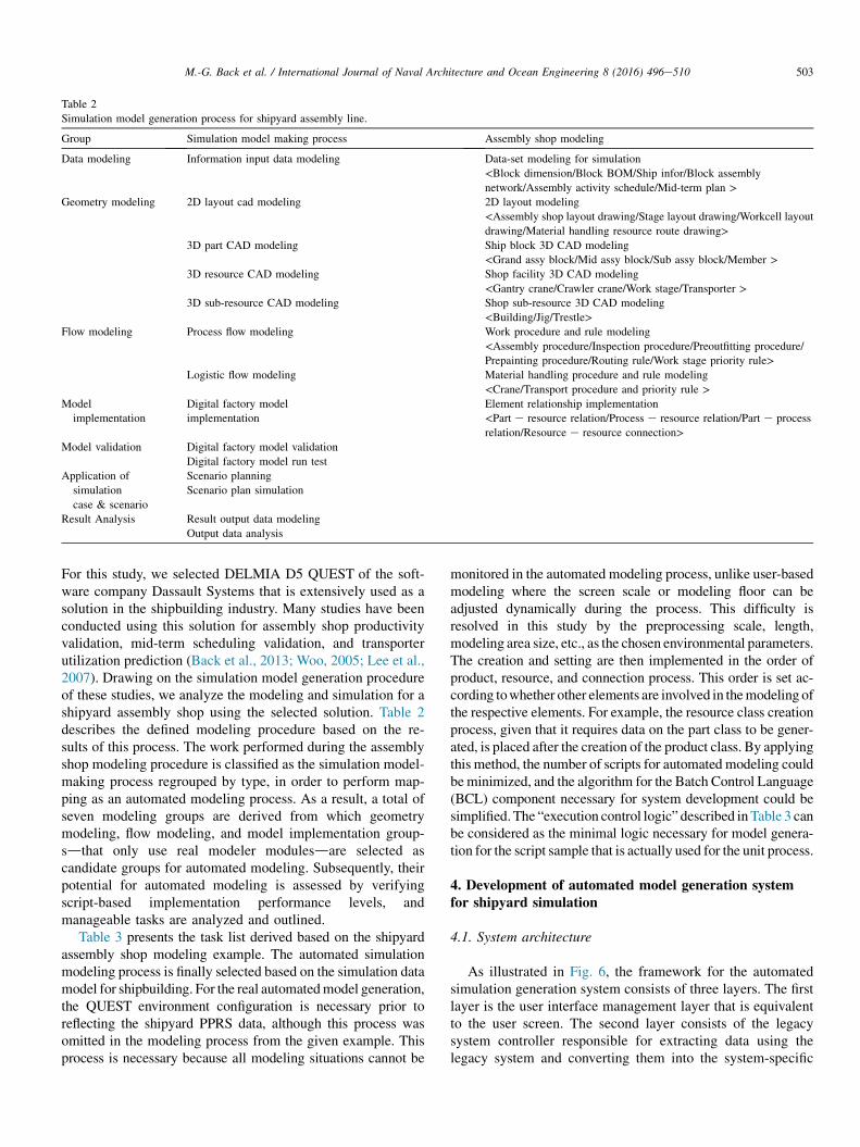
Table 2
Simulation model generation process for shipyard assembly line.
Group Simulation model making process Assembly shop modeling
Data modeling Information input data modeling Data-set modeling for simulation
<Block dimension/Block BOM/Ship infor/Block assembly
network/Assembly activity schedule/Mid-term plan >Geometry modeling 2D layout cad modeling 2D layout modeling
<Assembly shop layout drawing/Stage layout drawing/Workcell layout
drawing/Material handling resource route drawing>3D part CAD modeling Ship block 3D CAD modeling
<Grand assy block/Mid assy block/Sub assy block/Member >3D resource CAD modeling Shop facility 3D CAD modeling
<Gantry crane/Crawler crane/Work stage/Transporter >3D sub-resource CAD modeling Shop sub-resource 3D CAD modeling
<Building/Jig/Trestle>Flow modeling Process flow modeling Work procedure and rule modeling
<Assembly procedure/Inspection procedure/Preoutfitting procedure/
Prepainting procedure/Routing rule/Work stage priority rule>Logistic flow modeling Material handling procedure and rule modeling
<Crane/Transport procedure and priority rule >Model
implementation
Digital factory model
implementation
Element relationship implementation
<Part e resource relation/Process e resource relation/Part e process
relation/Resource e resource connection>Model validation Digital factory model validation
Digital factory model run test
Application of
simulation
case & scenario
Scenario planning
Scenario plan simulation
Result Analysis Result output data modeling
Output data analysis
503M.-G. Back et al. / International Journal of Naval Architecture and Ocean Engineering 8 (2016) 496e510
For this study, we selected DELMIA D5 QUEST of the soft-ware company Dassault Systems that is extensively used as asolution in the shipbuilding industry. Many studies have beenconducted using this solution for assembly shop productivityvalidation, mid-term scheduling validation, and transporterutilization prediction (Back et al., 2013; Woo, 2005; Lee et al.,2007). Drawing on the simulation model generation procedureof these studies, we analyze the modeling and simulation for ashipyard assembly shop using the selected solution. Table 2describes the defined modeling procedure based on the re-sults of this process. The work performed during the assemblyshop modeling procedure is classified as the simulation model-making process regrouped by type, in order to perform map-ping as an automated modeling process. As a result, a total ofseven modeling groups are derived from which geometrymodeling, flow modeling, and model implementation group-sdthat only use real modeler modulesdare selected ascandidate groups for automated modeling. Subsequently, theirpotential for automated modeling is assessed by verifyingscript-based implementation performance levels, andmanageable tasks are analyzed and outlined.
Table 3 presents the task list derived based on the shipyardassembly shop modeling example. The automated simulationmodeling process is finally selected based on the simulation datamodel for shipbuilding. For the real automatedmodel generation,the QUEST environment configuration is necessary prior toreflecting the shipyard PPRS data, although this process wasomitted in the modeling process from the given example. Thisprocess is necessary because all modeling situations cannot be
monitored in the automated modeling process, unlike user-basedmodeling where the screen scale or modeling floor can beadjusted dynamically during the process. This difficulty isresolved in this study by the preprocessing scale, length,modeling area size, etc., as the chosen environmental parameters.The creation and setting are then implemented in the order ofproduct, resource, and connection process. This order is set ac-cording towhether other elements are involved in themodeling ofthe respective elements. For example, the resource class creationprocess, given that it requires data on the part class to be gener-ated, is placed after the creation of the product class. By applyingthis method, the number of scripts for automated modeling couldbeminimized, and the algorithm for the Batch Control Language(BCL) component necessary for system development could besimplified. The “execution control logic” described inTable 3 canbe considered as the minimal logic necessary for model genera-tion for the script sample that is actually used for the unit process.
4. Development of automated model generation systemfor shipyard simulation
4.1. System architecture
As illustrated in Fig. 6, the framework for the automatedsimulation generation system consists of three layers. The firstlayer is the user interface management layer that is equivalentto the user screen. The second layer consists of the legacysystem controller responsible for extracting data using thelegacy system and converting them into the system-specific
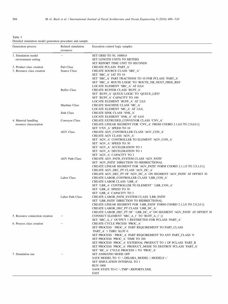
Table 3
Detailed simulation model generation procedure and sample.
Generation process Related simulation
resources
Execution control logic samples
1. Simulation model
environment setting
e SET GRID TO 50, 10000.0
SET LENGTH UNITS TO METERS
SET REPORT TIME UNIT TO SECONDS
2. Product class creation Part Class CREATE PCLASS ‘PART_A’
3. Resource class creation Source Class CREATE SOURCE CLASS ‘SRC_A’
SET ‘SRC_A’ IAT TO 10
SET ‘SRC_A’ PART FRACTIONS TO 10 FOR PCLASS ‘PART_A’
SET ‘SRC_A’ ROUTE LOGIC TO ‘ROUTE_NB_NEXT_FREE_RES’
LOCATE ELEMENT ‘SRC_A’ AT 0,0,0
Buffer Class CREATE BUFFER CLASS ‘BUFF_A’
SET ‘BUFF_A’ QUEUE LOGIC TO ‘QUEUE_LIFO’
SET ‘BUFF_A’ CAPACITY TO 100
LOCATE ELEMENT ‘BUFF_A’ AT 2,0,0
Machine Class CREATE MACHINE CLASS ‘MC_A’
LOCATE ELEMENT ‘MC_A’ AT 3,0,0,
Sink Class CREATE SINK CLASS ‘SNK_A’
LOCATE ELEMENT ‘SNK_A’ AT 4,0,0
4. Material handling
resource classcreation
Conveyor Class CREATE EXTRUDED_CONVEYOR CLASS ‘CNV_A’
CREATE LINEAR SEGMENT FOR ‘CNV_A’ FROM COORD 2.1,0,0 TO 2.9,0,0 []
SET ‘CNV_A’ SPEED TO 10
AGV Class CREATE AGV_CONTROLLER CLASS ‘AGV_CON_A’
CREATE AGV CLASS ‘AGV_A’
SET ‘AGV_A’ CONTROLLER TO ELEMENT ‘AGV_CON_A’
SET ‘AGV_A’ SPEED TO 30
SET ‘AGV_A’ ACCELERATION TO 1
SET ‘AGV_A’ DECELERATION TO 1
SET ‘AGV_A’ CAPACITY TO 2
AGV Path Class CREATE AGV_PATH_SYSTEM CLASS ‘AGV_PATH’
SET ‘AGV_PATH’ DIRECTION TO BIDIRECTIONAL
CREATE LINEAR SEGMENT FOR ‘AGV_PATH’ FORM COORD 2.1,1,0 TO 2.9,1,0 []
CREATE AGV_DEC_PT CLASS ‘AGV_DC_A’
CREATE AGV_DEC_PT OF ‘AGV_DC_A’ ON SEGMENT ‘AGV_PATH’ AT OFFSET 30
Labor Class CREATE LABOR_CONTROLLER CLASS ‘LBR_CON_A’
CREATE LABOR CLASS ‘LBR_A’
SET ‘LBR_A’ CONTROLLER TO ELEMENT ‘ LBR_CON_A’
SET ‘LBR_A’ SPEED TO 30
SET ‘LBR_A’ CAPACITY TO 2
Labor Path Class CREATE LABOR_PATH_SYSTEM CLASS ‘LBR_PATH’
SET ‘LBR_PATH’ DIRECTION TO BIDIRECTIONAL
CREATE LINEAR SEGMENT FOR ‘LBR_PATH’ FORM COORD 2.1,2,0 TO 2.9,2,0 []
CREATE LABOR_DEC_PT CLASS ‘LBR_DC_A’
CREATE LABOR_DEC_PT OF ‘ LBR_DC_A00 ON SEGMENT ‘AGV_PATH’ AT OFFSET 30
5. Resource connection creation e CONNECT ELEMENT ‘SRC_A_1’ TO ‘BUFF_A_1’ []
SET ‘SRC_A_1’ OUTPUT 1 RESTRICTED FOR PCLASS ‘PART_A’
6. Process class creation e CREATE CYCLE PRCESS ‘PROC_A’
SET PROCESS ‘ PROC_A’ PART REQUIREMENT TO PART_CLASS
‘PART_A’ 1 THRU SLOT 0
SET PROCESS ‘ PROC_A’ PART REQUIREMENT TO ANY PART_CLASS ‘0
SET PROCESS ‘PROC_A’ TIME TO 100
SET PROCESS ‘PROC_A’ EXTERNAL PRODUCT TO 1 OF PCLASS ‘PART_B
SET PROCESS ‘PROC_A’ PRODUCT_MODE TO DESTROY PCLASS ‘PART_A’
SET ‘MC_A’ CYCLE PROCESS 1 TO ‘PROC_A’
7. Simulation run e SET ANIMATIO MODE OFF
SAVE MODEL TO ‘C:yDELMIA_MODELyMODELSy’
SET SIMULATION INTERVAL TO 1
RUN 1000
SAVE STATS TO C:yTMPyREPORTS.XML
EXIT
504 M.-G. Back et al. / International Journal of Naval Architecture and Ocean Engineering 8 (2016) 496e510

Fig. 6. Architecture of shipyard simulation model generation system.
505M.-G. Back et al. / International Journal of Naval Architecture and Ocean Engineering 8 (2016) 496e510
data format, the simulation data management system respon-sible for compatibility checks of the extracted data and for themanagement of the Database Management System (DBMS),and the simulation engine controller responsible for generatingcommands for simulation model generation based on theconverted data and controlling simulation software. The thirdlayer is the DBMS responsible for storing and managing thedata defined by the PPRS-M structure (Fig. 5).
Herein, we describe in more detail the second layer, that is,the legacy system controller. This controller extracts the datanecessary for the simulation model generation from the ship-yard legacy system. This consists of MES, ERP, APS, andothers, that in turn contain most production information. Thecontroller then converts them into the data for the simulationmodel generation that consists of the PPRS-M. The simulationdata management system is the part that implements thebehavior functions within the system, with the exception of theinter-system connection in the business façade, businesscomponent, and data access component layers. According tothe Component Based Development (CBD) methodology, thebusiness façade plays the role of the access point for thefunction based on the system design method, whereas thebusiness component implements major functions, and the dataaccess component implements the unit function related to thedatabase connection (Whitehead, 2002; Oh et al., 2009).
The simulation engine controller is consisted of themodeling script controller that generates the simulation modelgeneration command, based on the corresponding data inaccordance to the procedure defined in Table 3, and thesimulation S/W controller that provides socket communicationwith the simulation system, in order to generate the simulationmodel using the generation command. We define the simula-tion model generation process, the core function of the entiresystem, using the sequence diagram of Fig. 7. This is exten-sively used in defining the system flow among the UnifiedModeling Language (UML) that is in turn, extensively used in
system design. Fig. 7 presents the definitions of the in-teractions and interfaces between the legacy system controllerresponsible for data export from the shipyard legacy systemchassis, the simulation data management system responsiblefor simulation model generation and correction, and thesimulation engine controller responsible for the simulationengine control.
4.2. Deployment of simulation model generation system
As illustrated in Fig. 7, the simulation model generationsystem consists of the user interface that implements thescreen-associated function for the user in order to verify theprocess, the legacy system controller that extracts data fromthe legacy system to generate the simulation model, thesimulation data management system that checks thecompatibility of the extracted data and manages the DBMS,and the simulation engine controller that controls the simu-lation model generation and the simulation system. The userinterface and module development environment are imple-mented within the .net framework 4.0 C#, and the DBMSusing the SQL Server 2008. First, the legacy systemcontroller obtains the data necessary for the simulation modelgeneration by extracting them from the shipyard legacysystem as shown in Fig. 7. The obtained data are thus storedin the database defined from the PPRS-M views. The simu-lation data management system is implemented in threelayers of a business façade, business component, and dataaccess component. The simulation engine controller gener-ates the simulation model generation command based on thedata used for the simulation model generation by a userquery. The generated command is configured to implementthe simulation model generation using the socket communi-cation method known to be stable among the APIs supportedby the simulation engine. Lastly, the user interface has alayout that allows the user to employ the functions provided
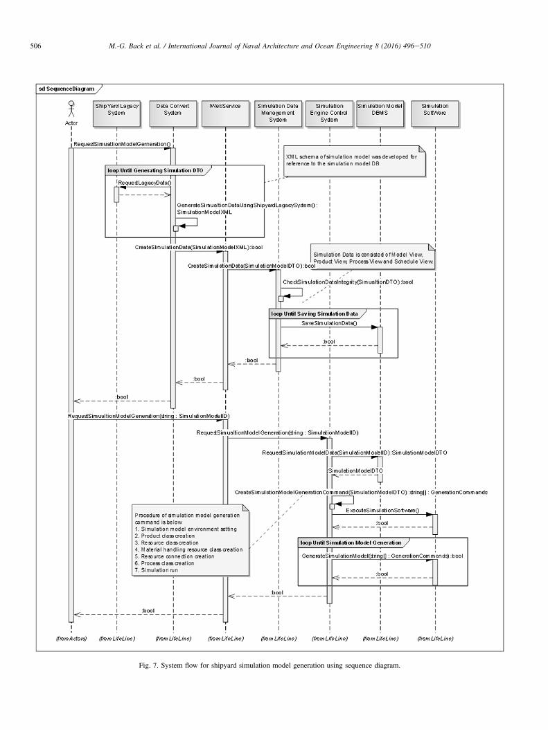
Fig. 7. System flow for shipyard simulation model generation using sequence diagram.
506 M.-G. Back et al. / International Journal of Naval Architecture and Ocean Engineering 8 (2016) 496e510

Fig. 8. User interface of automated model generation system.
507M.-G. Back et al. / International Journal of Naval Architecture and Ocean Engineering 8 (2016) 496e510
by the legacy system controller, the simulation data man-agement system, and the simulation engine controller, asshown in Fig. 8. The user obtains the data from the legacysystem on the user interface, generates the command for thesimulation model generation based on the shipyard datastored in the database, and generates a simulation model withthe simulation engine controller.
Table 4
Component of shipyard panel line.
Type Detail type Name Desc
Product Member Plate Mem
Tap Piece Recta
Main Plate Produ
Stiffener Long
Block SA-Block Block
Resource Machine Welding Line
Marking Mach
Fitup Spot
Crane 60T OHC Over
20T OHC Over
Conveyor Conveyor Accu
Process Assembly Tack Welding Proce
Panel Front Welding Front
Turn Over Proce
Panel Back Welding Back
NC Marking Maki
Cutting Proce
Assembly e Fitup Assem
Assembly e Welding Assem
5. Application of automated model generation system atshipyard panel line
5.1. Analysis of shipyard panel line
The vessels manufactured in a shipyard have a complexproduct mix and unique order-based pieces, with the
ription
ber of composing main plate
ngular piece of steel used to weld both plates
ct consisting of multiple plates
itudinal stiffener
of subassembly consisting main plate and stiffener to produce middle block
welding machine to assembly product.
ine to work for marking to identify products
welding machine to hold member like stiffener
head crane used for turn over
head crane used for transfer light product like plates, stiffeners
mulating conveyor to transport main plate and SA-block
ss to arrange plates, tap piece and weld them partially
side welding process for making main plate
ss to flip over front side to weld plate back side
side welding process for making main plate
ng process of where to put the stiffeners
ss to cut tap-piece
bly process of weld stiffeners partially on the main plate
bly process of weld stiffeners on the main plate

Fig. 9. Process flow analysis considering resource and product.
508 M.-G. Back et al. / International Journal of Naval Architecture and Ocean Engineering 8 (2016) 496e510
exception of some series lines. Therefore, most of the ship-building processes are job-shop methods with a typically lowproductivity. However, a panel line adheres to an iterativeprocess for producing panel blocks of similar shapes and its
Fig. 10. Data acquisition from legacy system and
production process can be standardized using the flow pro-duction method that allows mass production. Consequently,we chose the panel line as the target process for applying theproposed system.
simulation model generation using system.

509M.-G. Back et al. / International Journal of Naval Architecture and Ocean Engineering 8 (2016) 496e510
For the definition of the major elements of the panel line,we classified them into product, process, and resource, asdescribed in Table 4. The product consists of a main plate thatconstitutes the most sub member, produced by the welding ofother plates, and a subassembly block produced by welding ofthe main plate and the stiffener. The process consists of tackwelding, panel front welding, turn over, panel back welding,NC marking, cutting, assembly fit up, and assembly welding.Fig. 9 presents the main equipment for an individual processand transport equipment, as well as related product informa-tion. First, the main plate is produced by welding the tap pieceto fix several additional plates, and a welding machine is usedto close the front side plate-to-plate gaps. Rear-side welding isthen performed after turning the plates over with a crane. Amarking machine is used to mark the position of the stiffeneron the main plate, and the stiffener is prewelded with a fit upmachine. A subassembly panel is then completed by weldingthe prewelded piece with a welding machine. The main lineflow of the panel line occurs through an accumulation-typeconveyor, and the members, such as stiffeners and plates, aremoved with a 20 T overhead crane. A panel block is producedby assembling several subassembly blocks, but this process isexcluded from the system application in this study.
5.2. Application of an auto model generation system
We validated the simulation model generation system to theshipyard panel block production line simulation model.Among the individual systems that constitute the overall sys-tem framework, the data convert system is used for extractingthe data necessary for simulation modeling using the legacysystem. Given that shipyards have different data managementmethods and data structures, and maintain high-informationsecurity, directly obtaining data from a shipyard legacy sys-tem is a great challenge. Therefore, we obtain the data from ashipyard legacy system in the neutral XML format (Fig. 10(a))for simulation (Lee et al., 2013). The obtained simulationmodel data is converted into the format and functioncompatible with the proposed system via the simulation datamanagement system. Moreover, the BCL, the simulationmodel generation command, is generated (Fig. 10(b)) by thesimulation control system based on the converted data. Prior tothe simulation model generation, the BCL generates and thenimplements the initial simulation instant data definition, suchas the temporal and spatial unit configuration and the initialmodel dimensions, using the data from the simulation view ofthe shipyard data model. Subsequently, it implements productclass generation, attributes assignment, and size configuration,using the produced view data. Using the resource view data,resource data are generated, such as resource class generation,resource instance generation, attributes assignment, andresource connection. With the BCL implementing thesefunctions, the shipyard panel line simulation model that iscomposed of the product, process, and resource (shown inTable 4) is generated using the simulation engine controller.Given that no separate model for schedule representation isavailable, this is defined as the attribute of the individual
products. In addition, data that cannot be generated with BCL,such as CAD, are generated preliminarily and used in the formof a library.
The performance test of the simulation model generationsystem is carried out in an environment with Intel i5 CPU,4 GB RAM, and 1 GB VGA RAM. The test simulation modelis comprised of resources (source, machine, buffer, sink,crane, and path) and a process, which are entities defined inQUEST with 783 classes and 875 class elements. After theentities are generated, the pre- and post-link relations betweenthe elements are set. The simulation model generation systemgenerates about 7000 BCL commands for simulation modelgeneration. Approximately 1 min is required for simulationmodel generation using the BCL commands in the test envi-ronment. To compare this with the modeling time required byan engineer using a general method, scenarios of model gen-eration by a skilled engineer and an unskilled general engineerare defined. It is assumed that a skilled engineer carries out6 BCLs/min using the user interface and the unskilled,beginner modeler carries out 3 BCLs/min. Under thisassumption, engineer using this system for model generationsaves approximately 2.6 h than the skilled modeler and 10.2 hthan the beginner modeler.
The simulation model generation is completed if detailedmodeling is performed by adding rules to the initially gener-ated simulation model, specific to individual shops. However,because detailed modeling is implemented via script codingusing a high degree-of-freedom, the resulting model qualitiesvary greatly from one modeler to another. Furthermore,because of the high degree of modeling complexity, its stan-dardization is a great challenge. The system developed in thisstudy has a feature that allows the generation of a model byBCL, to generate the initial model, based on the predefineddata, while. A simulation model generated according to thismethod requires less modeling time than a conventionalmodeler. It is expected that the modeler can focus more on thedetailed modeling that reflects work-specific rules. In addition,the proposed method has the advantage of preventing simu-lation model generation for each modeler with other methods,thus contributing to the standardization of the shipyardsimulation model generation.
6. Conclusions
In this paper, the data model for shipyard productionsimulation model generation was defined by analyzing theiterative simulation modeling procedure. The shipyard pro-duction simulation data model defined in this study containsthe information necessary for the conventional simulationmodeling procedure and can serve as a basis for simulationmodel generation. We developed a system capable of gener-ating simulation models using the internal model generationprotocol (BCL), and socket communication by applying theconstructed model for simulation model generation to QUEST,a solution extensively used for production simulation. Theefficacy of the developed system was validated by applying itto the simulation model generation of the panel block

510 M.-G. Back et al. / International Journal of Naval Architecture and Ocean Engineering 8 (2016) 496e510
production line for company S. By implementing the initialsimulation model generation process, which was performed inthe past with a simulation modeler, the proposed systemsubstantially reduced the modeling time. In addition, byreducing the difficulties posed by different modeler-dependentgeneration methods, the proposed system makes the stan-dardization of the simulation model quality possible. Thisleads to another advantage, in that, the simulation modeler canfocus more on detailed modeling that reflects work-specificrules using script coding.
In regard to the limitations of the proposed system, we canindicate that this is a basic simulation model generationmethodology for individual projects, and cannot manage thelogic generation for expressing detailed work rules. Work rulesare difficult to standardize because of different features andflow on a case-by-case. This will have to be addressed infuture research that focuses on modeler development usingnatural language and diagrams. Another limitation of theproposed system is that it was not applied to multiple pro-duction simulation solutions. Nevertheless, despite these lim-itations, the development of this system is significant in that itsimplified the modeling region using technology based on aneutral data format converted from production data. It storesdata required for the shipbuilding simulation model generationand defines manageable data models, thus contributing to thereduction of the total modeling time when used for simulationmodel generation and maintenance/repair. The methodsapplied in this study are expected to have time and costreduction effects when applied to digital production tech-niques in shipyards, which will lead to more active applica-tions of simulation technologies.
Acknowledgments
This paper is composed of results of the “Leaders Industry-university Cooperation” Project, supported by the Ministry ofEducation, Science & Technology (MEST) and the NationalResearch Foundation of Korea (NRF). Also, the nationalproject (Development of the simulation based productionmanagement system for the middle-sized shipbuilding com-panies; No. 10050495), which is supported by industry coretechnology development business of ministry of trade, in-dustry and energy, has been supporting this research.
References
Alfeld, L.E., Pilliod, C.S., Wilkins, J.R., 1998. The virtual shipyard: a simu-
lation model of the shipbuilding process. J. Ship Prod. 14 (1), 33e40.
Back, M.G., Kim, Y.G., Hwang, I.H., Lee, K.K., Ryu, C.H., Shin, J.G., 2013.
Design and development of scenario-based simulation system to improve
shipbuilding execution scheduling assessment : a case study on panel line.
Trans. Soc. CAD/CAM Eng. 18 (3), 211e223.
Harward, G., Harrell, C., 2006. Assessment of the NIST shop data model as a
neutral file format. In: Proceedings of the 2006 Winter Simulation Con-
ference, Monterey, USA, pp. 941e946.
Hwang, I.H., Song, J.K., Back, M.G., Ryu, C.H., Lee, K.K., Shin, J.G., 2013.
Development of shipbuilding execution scheduling support system using
mobile device : a case study for a panel block assembly shop. J. Soc. Nav.
Archit. Korea 50 (4), 262e271.
Johansson, M., Johansson, B., Sjoogh, A., Leong, S., Riddick, F., Lee, Y.T.,
Shao, G., Klingstam, P., 2007. A test implementation of the core
manufacturing simulation data specification. In: Proceedings of the 2007
Winter Simulation Conference, Washington, USA, pp. 1673e1681.
Kang, H.S., 2007. A Study on the Automated Generation of Simulation Model
Based on PPR Information. Dissertation. Sungkyunkwan University.
Lee, C.J., Lee, J.H., Woo, J.H., Shin, J.G., Ryu, C.,H., 2007. A study on
discrete event simulation of shipyard outdoor block movement. J. Soc.
Nav. Archit. Korea 44 (6), 647e656.Lee, D.K., Back, M.G., Lee, K.K., Park, J.S., Shin, J.G., 2013. Study on
simulation model generation of a shipyard panel block shop using a neutral
data format for production information. J. Soc. Nav. Archit. Korea 50 (5),
314e323.
Lee, D.K., Kim, Y.M., Hwang, I.H., Oh, D.K., Shin, J.G., 2014. Study on a
process-centricmodelingmethodology for virtual manufacturing of ships and
offshore structures in shipyards. Int. J. Adv. Manuf. Technol. 71, 621e633.Lee, J.H., Kim, S.H., Lee, K.H., 2011a. Integration of evolutional BOMs for
design of ship outfitting equipment. Comput. Aided Des. 44 (3), 253e273.
Lee, J.Y., Kang, H.S., Noh, S.D., Woo, J.H., Lee, P.L., 2011b. NESIS: a neutral
schema for a web-based simulation model exchange service across hetero-
geneous simulation software. Int. J.Comput. Integr.Manuf. 24 (10), 948e969.
Lu, R.F., Qiao, G., McLean, C., 2003. Nist XML simulation interface speci-
fication at boeing : a case study. In: Proceedings of the 2003 Winter
Simulation Conference, LA, USA, pp. 1230e1237.
Oh, D.K., Shin, J.G., Choi, Y.R., Yao, Y.H., 2009. Development of a naval ship
product model and management system. J. Soc. Nav. Archit. Korea 46 (1),
43e56.Song, Y.J., Lee, D.G., Choe, S.W., Shin, J.G., 2009. A simulation-based ca-
pacity analysis of a block-assembly process in ship production planning.
J. Soc. Nav. Archit. Korea 46 (1), 78e86.
Song, Y.J., Woo, J.H., Shin, J.G., 2011. Research on systematization and
advancement of shipbuilding production management for flexible and agile
response for high value offshore platform. Int. J. Nav. Archit. Ocean Eng. 3
(3), 181e192.
Sly, D., Moorthy, S., 2001. Simulation data exchange (SDX) implementation
and use. In: Proceedings of the 2001 Winter Simulation Conference,
Arlington, USA, pp. 1473e1477.
Watson, E.F., Medeiros, D.J., Sadowski, R.P., 1997. A simulation-based
backward planning approach for order-release. In: Proceedings of the 1997
Winter Simulation Conference, Atlanta, USA, pp. 765e772.
Wang, P., Mohamed, Y., Abourizk, S.M., Rawa, A.T., 2009. Flow production
of pipe spool fabrication: simulation to support implementation of lean
technique. J. Constr. Eng. Manag. 135 (10), 1027e1038.
Whitehead, K., 2002. Component-based Development: Principles and Plan-
ning for Business Systems. Pearson Education, London.
Woo, J.H., Lee, K.K., Jung, H.R., Kwon, Y.D., Shin, J.G., 2005. A framework
of plant simulation for a construction of a digital shipyard. J. Soc. Nav.
Archit. Korea 42 (2), 165e174.
Woo, J.H., Song, Y.J., Shin, J.G., 2009. Research on a simulation-based ship
production support system for middle-sized shipbuilding companies. Int. J.
Nav. Archit. Ocean Eng. 1, 70e77.
Woo, J.H., 2005. Modeling and Simulation of Indoor Shop System of Ship-
building by Integration of the Product, Process, Resource and Schedule
Information. Dissertation. Seoul National University.