A Storage Menagerie: SANs, Fibre Channel, Replication and Networks
36
A Storage Menagerie: SANs, Fibre Channel, Replication and Networks Replication and Networks David L. Black Distinguished Engineer NANOG 51 Conference Miami, FL – January 30, 2011 1 © Copyright 2010 EMC Corporation. All rights reserved.
Transcript of A Storage Menagerie: SANs, Fibre Channel, Replication and Networks

A Storage Menagerie: SANs, Fibre Channel, Replication and NetworksReplication and Networks
David L. BlackDistinguished Engineer
NANOG 51 ConferenceMiami, FL – January 30, 2011
1© Copyright 2010 EMC Corporation. All rights reserved.

Storage Networking: NAS and SAN
• DAS: Direct Attached Storage (not networked)• NAS: Network Attached Storage: File
– Distributed filesystems: Serve files and directories• Shared access is defaultShared access is default
– NFS (Networked File System)– CIFS (Common Internet File System)
• SAN: Storage Area Network: Block• SAN: Storage Area Network: Block– Distributed (logical) disks: Serve blocks
• Non-shared access is default• Sharing requires clustering (application filesystem or volume mgr )• Sharing requires clustering (application, filesystem or volume mgr.)
– SCSI (Small Computer System Interface)-based• Examples: iSCSI, Fibre Channel (FC)
• Focus of this talk: SAN technology protocols and networks
2© Copyright 2010 EMC Corporation. All rights reserved.
• Focus of this talk: SAN technology, protocols and networks

SAN Storage Arrays: Overview
• Make logical disks out of physical disksp y– Array contains physical disks, servers access logical disks
• High reliability/availability:– Redundant hardware server-to-storage multipathingRedundant hardware, server to storage multipathing– Disk Failures: Data mirroring, parity-based RAID– Internal Housekeeping (e.g., disk scrubbing)
• Can often predict failures (e g replace drives before they fail)Can often predict failures (e.g., replace drives before they fail)
– Power Failures: UPS used, entire array may be battery-backed• Ride through power glitches, orderly shutdown on power failure• Battery-backed write-back cache, may dump to disk on power failureBattery backed write back cache, may dump to disk on power failure
• Extensive storage functionality– Slice, stripe, concatenate, thin provisioning, dedupe, auto-tier, etc.
Snapshot clone copy remotely replicate etc
3© Copyright 2010 EMC Corporation. All rights reserved.
– Snapshot, clone, copy, remotely replicate, etc.

SAN Storage Arrays: Examples
• Small SAN array: 3U rack-mountSmall SAN array: 3U rack mount– 8 Fibre Channel ports (up to 8Gb/sec each)
– Minimum: 4 disk drives, up to 2TB raw capacity/drivep p y
– Expands to 75 drives, up to 150TB raw capacity
– Usable capacity depends on array configuration
• Very large SAN array: 10+ rack-sized cabinets– Up to 128 ports of 8Gb/sec Fibre Channel
– 1Gb/sec and 10Gb/sec Ethernet also available
– Up to 2400 drives, 2PB max usable capacity
4© Copyright 2010 EMC Corporation. All rights reserved.

Storage Protocol Classes
StorageNetwork
StorageNetwork
Server to Storage Access• SAN: Fibre Channel, iSCSI
Storage Replication• Array to Array, primarily SAN
• NAS: NFS, CIFS • Often based on server to storage protocol
5© Copyright 2010 EMC Corporation. All rights reserved.

Why Storage Replication?
• Disasters Happen: pp– Power out
– Phone lines down
Water everywhere– Water everywhere
• The Systems are Down! Syst s a o
• The Network is Out!
• This is a problem ...
6© Copyright 2010 EMC Corporation. All rights reserved.

Storage Replication Rationale
Miami ChicagoHurricane Andrew wasMiami ChicagoHurricane Andrew was NOT in Chicago
Store the DataStore the Data in Two Places
Storage Array Storage Array
Storage Replication
7© Copyright 2010 EMC Corporation. All rights reserved.
Storage Array Storage Array

Storage Replication: 2 Types
• Synchronous Replication: Identical copy of datay p py – Server writes not acknowledged until data replicated
– Distance limited: Rule of thumb – 5ms round-trip or 100km (60mi)
Failure recovery: Incremental copy to resychronize– Failure recovery: Incremental copy to resychronize
• Asynchronous Replication: Delayed consistent copy of data– Server writes acknowledged before data replicated
– Used for higher latencies, longer distances (arbitrary distance ok)
– Data consistency after failure: Manage replicated writes
• Replication often based on access protocol (e g FC iSCSI)• Replication often based on access protocol (e.g., FC, iSCSI)– Additional replication logic for error recovery, data consistency, etc.
– Resulting replication protocol is usually vendor-specific
8© Copyright 2010 EMC Corporation. All rights reserved.

Storage Replication and Network Failures
• Initial Reaction: Ignore network failure, hope it goes away– It often does ☺, but sometimes it doesn’t – Worst case: Initial indication of rolling site disaster
• Failure goes away: Resume storage replication, catch up ( )– Don’t recopy all the data !! (bad protocol design)
– Track what still needs to be replicated (e.g., bitmap, log)
• Site Disaster: Ensure remote data copy is consistentC i t t d t P ibl “ f il” d t i– Consistent data copy = Possible “power-fail” data image
• Formal Requirement: Dependent write consistency• Database example: Data table write depends on transaction log write
– All replication: Turn on/off consistently (with respect to server I/O) p / y ( p / )• May involve multiple arrays at each site, each with own network connections
– Asynchronous replication: Organize replicated writes• Ordered log of writes: Ok at small to medium scale
L l G it l t i ll t t it
9© Copyright 2010 EMC Corporation. All rights reserved.
• Larger scale: Group writes, apply groups atomically at remote site

Storage Replication: Network Sizing
• Characterize (measure) the I/O workloadM i I/O ffi b i l i ☺– Measuring I/O traffic beats guessing almost every time ☺
• Synchronous replication: Size network for worst case– I/O outruns network: Servers slow down – Provide network capacity to handle peak I/O loadProvide network capacity to handle peak I/O load
• Asynchronous replication: Size network to limit data loss– I/O outruns network: Data queue builds up in source array
• No immediate impact on serversDi t D t d d t i fli ht b th l t• Disaster: Data queue and data in flight are both lost
– Limit data loss by limiting size of source data queue• RPO: Recovery Point Objective (typically measured in minutes/seconds)• Maximum RPO = Maximum amount of data that may be lost on disaster
– Provision network capacity to limit source data queue size• Plus headroom for unexpected traffic peaks, anticipated growth
• Related term: RTO (Recovery Time Objective)– RTO = Wall clock time required to restore application(s) after disaster
10© Copyright 2010 EMC Corporation. All rights reserved.
RTO Wall clock time required to restore application(s) after disaster

The SCSI Protocol Family:Foundation of SAN StorageFoundation of SAN Storage
11© Copyright 2010 EMC Corporation. All rights reserved.

SCSI (“scuzzy”)
• SCSI = Small Computer System Interface p y – But used with computers of all sizes
• Client-server architecture (really master-slave) ( ) ( )– Initiator (e.g., server) accesses target (storage)
– Target is slaved to initiator, target does what it’s told
• Target could be a disk drivea g t ou a s – Embedded firmware, no admin interface
– Resource-constrained by comparison to initiator• SCSI target controls resources incl data transfer (e g write)• SCSI target controls resources, incl. data transfer (e.g., write)
• I/O performance rule of thumb: Milliseconds Matter– 5ms round-trip delay can cause visible performance issue
12© Copyright 2010 EMC Corporation. All rights reserved.

SCSI Architecture
• SCSI Command Sets & Transports – SCSI Command sets: I/O functionality
– SCSI Transports: Communicate commands and data– Same command sets used with all transports
I t t SCSI d t• Important SCSI command sets– Common: SCSI Primary Commands (SPC)
• All SCSI devices (e.g., INQUIRY, TEST UNIT READY)Disk: SCSI Block Commands (SBC)– Disk: SCSI Block Commands (SBC)
• Concurrent block-addressed I/O commands for disks, storage arrays– Tape: SCSI Stream Commands (SSC)
• Single stream of I/O commands to tape deviceg / p
• SCSI Transport examples– FC: Fibre Channel (via SCSI Fibre Channel Protocol [FCP])– iSCSI: Internet SCSI
13© Copyright 2010 EMC Corporation. All rights reserved.
– SAS: Serial Attached SCSI

The SCSI Protocol Family
SCS (S )SCSI Architecture (SAM) & Commands (SCSI-3) Fibre Channel
FICON IP (RFC 4338)FCP FC 4
P ll l
(mainframe) IP (RFC 4338)FCP FC-4
iSCSIParallel SCSI &
SAS FC-1FC-2
FC-0
iSCSITCPIP
SCSI & SAS Cables
FC Fibers & Switches
Any IPNetwork
14© Copyright 2010 EMC Corporation. All rights reserved.

The SCSI Protocol Family and SANs
SCS (S )SCSI Architecture (SAM) & Commands (SCSI-3) Fibre Channel
FICON IP (RFC 4338)FCP
DAS(Direct
Attached)
FC SAN
P ll l
(mainframe) IP (RFC 4338)FCP
iSCSI
IP SANAttached)
Parallel SCSI &
SAS FC-1FC-2
FC-0
iSCSITCPIP
SCSI & SAS Cables
FC Fibers & Switches
Any IPNetwork
15© Copyright 2010 EMC Corporation. All rights reserved.
IP SAN: iSCSI
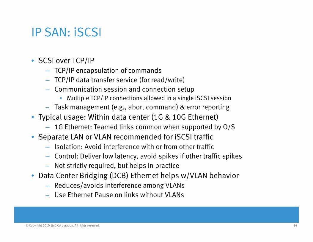
• SCSI over TCP/IP– TCP/IP encapsulation of commands– TCP/IP data transfer service (for read/write)– Communication session and connection setup
• Multiple TCP/IP connections allowed in a single iSCSI session
Task management (e g abort command) & error reporting– Task management (e.g., abort command) & error reporting
• Typical usage: Within data center (1G & 10G Ethernet)– 1G Ethernet: Teamed links common when supported by O/S
• Separate LAN or VLAN recommended for iSCSI traffic• Separate LAN or VLAN recommended for iSCSI traffic– Isolation: Avoid interference with or from other traffic– Control: Deliver low latency, avoid spikes if other traffic spikes– Not strictly required but helps in practiceNot strictly required, but helps in practice
• Data Center Bridging (DCB) Ethernet helps w/VLAN behavior– Reduces/avoids interference among VLANs– Use Ethernet Pause on links without VLANs
16© Copyright 2010 EMC Corporation. All rights reserved.

iSCSI Example: Live Virtual Machine Migration Move running Virtual Machine across physical serversMove running Virtual Machine across physical servers
Shared storage iSCSI is a common
C:Shared storage
enables a VM to move without moving its data
iSCSI is a common way to add shared
storage to a network
17© Copyright 2010 EMC Corporation. All rights reserved.

The SCSI Protocol Family and Fibre Channel
SCS (S )SCSI Architecture (SAM) & Commands (SCSI-3) Fibre Channel
FICON IP (RFC 4338)FCP
FC SAN
P ll l
(mainframe) IP (RFC 4338)FCP
iSCSIParallel SCSI &
SAS FC-1FC-2
FC-0
iSCSITCPIP
SCSI & SAS Cables
FC Fibers & Switches
Any IPNetwork
18© Copyright 2010 EMC Corporation. All rights reserved.

Fibre Channel: Introduction
• FC Communication: Based on frames– Frame Header: 24 bytes– Frame Payload: Up to 2112 bytes (holds at least 2kB of data)
• FC ports have typesFC ports have types– N_Ports: Servers or Storage– F_Ports: Switch ports to communicate with N_Ports– E Ports: Switch ports to communicate with switchesE_Ports: Switch ports to communicate with switches
• FC ports and switches assembled into a “Fabric”– Frame routing: FSPF (FC Fabric adaptation of OSPF)
Fabric switch count limit 239 (current practice 60)– Fabric switch count limit: 239 (current practice: ~60)– Fabric supports server/storage port discovery & management
• Fabric scale: Up to thousands of ports
19© Copyright 2010 EMC Corporation. All rights reserved.

Native FC Links
• SAN FC links: Always opticaly p– FC disk drive interfaces are different (copper, no shared access)
• Link encoding: 8b/10b (Like 1Gig Ethernet)– Error detection Embedded synchronizationError detection, Embedded synchronization– Control vs. data word identification
• Links are always-on (IDLE control word)S d 1 2 4 8 Gbi / ( i l l i l)• Speeds: 1, 2, 4, 8 Gbit/sec (single lane serial)
– New: “16” Gbits/sec uses 64b/66b, not 8b/10b (32GFC is next)– Limited inter-switch use of 10Gbit/sec (also uses 64b/66b)
• Credit based flow control (not pause/resume or XON/XOFF)– Buffer credit required to send (separate credit pool per direction)– FC link control operations return credits to sender
20© Copyright 2010 EMC Corporation. All rights reserved.
p

FC timing and error recovery
• Strict timing requirements– R_A_TOV: Deliver FC frame or destroy it (typical: 10sec)
• Failure to do so can corrupt data due to FC exchange ID reuse– Timeout budget broken down into smaller per-link timeouts
• E D TOV typical 1sec (round trip) also used to detect link failures• E_D_TOV, typical 1sec (round trip), also used to detect link failures
• Heavyweight error recovery: No reliable FC transport protocol– Disk: Retry entire server I/O (30sec or 60sec timeout is typical)
Tape: Stop figure out what happened and continue from there– Tape: Stop, figure out what happened and continue from there• Streaming tape drive stops streaming (ouch!)
• FC is *very* drop-sensitive– Congestion: Overprovision to avoid congestion-induced drops– Congestion: Overprovision to avoid congestion-induced drops– Errors: Rule of thumb: 10–15 BER (Bit Error Rate) or better
• Native FC optics in data centers run at 10–18 BER or better
• Reminder: SCSI I/O is *very* latency sensitive
21© Copyright 2010 EMC Corporation. All rights reserved.
Reminder: SCSI I/O is very latency sensitive

The SCSI Protocol Family and Fibre Channel
SCS (S )SCSI Architecture (SAM) & Commands (SCSI-3) Fibre Channel
FICON IP (RFC 4338)FCP FC 4
P ll l
(mainframe) IP (RFC 4338)FCP FC-4
iSCSIFC/IPiFCP
Ethernet
FCoEParallel SCSI &
SASMPLS
FCPW
FC-1FC-2
FC-0
iSCSITCPIP
iFCP
IPTCP
DCB(“lossless”)
Ethernet
SCSI & SAS Cables
MPLS Networks
PW
FC Fibers & Switches
Any IPNetwork
Any IPNetwork
22© Copyright 2010 EMC Corporation. All rights reserved.
Ethernet

The SCSI Protocol Family and Fibre Channel
SCS (S )SCSI Architecture (SAM) & Commands (SCSI-3) Fibre Channel
FICON IP (RFC 4338)FCP
FCDistance
FC(oE) SAN
P ll l
(mainframe) IP (RFC 4338)FCP
iSCSIFC/IPiFCP
Extension
Ethernet
FCoEParallel SCSI &
SAS FC-1FC-2
FC-0
iSCSITCPIP
iFCP
IPTCP
MPLSFCPW
DCB(“lossless”)
Ethernet
SCSI & SAS Cables
FC Fibers & Switches
Any IPNetwork
Any IPNetwork
MPLS Networks
PW
23© Copyright 2010 EMC Corporation. All rights reserved.
Ethernet

FC Distance Extension
• Always between FC switches (E_Ports)– Primarily for storage replication (sync or async)
• Problem: Credit based flow control is distance sensitive– Solution: FC switches can provide additional buffering and credits
1. Simple: Extend native FC inter-switch link– Dark fiber or xWDM, no flow control (FC link control passed through)
2. Transparent: FC GFPT and FC pseudowire (pause/resume)– GFPT: (Asynchronous) Generic Framing Procedure – Transparent– FC PW (pseudowire): Extend FC over MPLS
3. Gateway-based: FC/IP and iFCP (TCP/IP)– TCP used for reliable delivery and flow control– Not transparent: Gateways used at extension endpoints
24© Copyright 2010 EMC Corporation. All rights reserved.
FC Pseudowire (PW): FC over MPLS
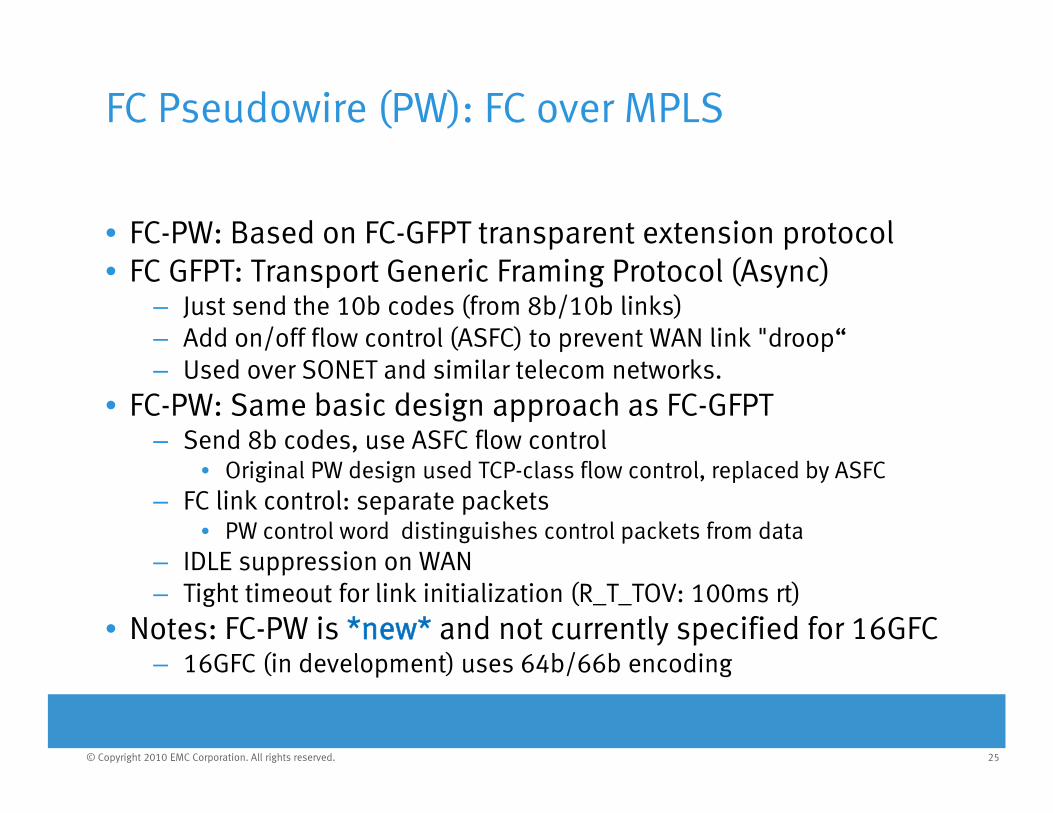
• FC-PW: Based on FC-GFPT transparent extension protocol• FC GFPT: Transport Generic Framing Protocol (Async)
– Just send the 10b codes (from 8b/10b links)– Add on/off flow control (ASFC) to prevent WAN link "droop“ – Used over SONET and similar telecom networks.
• FC-PW: Same basic design approach as FC-GFPT– Send 8b codes, use ASFC flow control
• Original PW design used TCP-class flow control, replaced by ASFC– FC link control: separate packets
• PW control word distinguishes control packets from dataIDLE suppression on WAN– IDLE suppression on WAN
– Tight timeout for link initialization (R_T_TOV: 100ms rt)• Notes: FC-PW is *new* and not currently specified for 16GFC
16GFC (in development) uses 64b/66b encoding
25© Copyright 2010 EMC Corporation. All rights reserved.
– 16GFC (in development) uses 64b/66b encoding

FC/IP and iFCP
• FC Switch to FC Switch extension via TCP/IP– E_D_TOV timeout (typically 1 sec rt) must be respected– Protocols include latency measurement functionality
• FC/IP: More common protocol– Only used for FC distance extension
• iFCP: More complex specification– FC distance extension: iFCP address transparent mode– iFCP not used for connection to servers or storage
• iFCP address translation mode (specified for this usage): Deprecated (Historic)
• iSNS name server used to set up iFCPiSNS l b d ith iSCSI– iSNS can also be used with iSCSI
– FC/IP has to be preconfigured• iFCP is going away (being replaced by FC/IP in practice)
26© Copyright 2010 EMC Corporation. All rights reserved.

FC/IP Network Customer Examples:A h St R li tiAsynchronous Storage Replication
• Financial Customer A (USA):– ~2 PB (Peta Bytes !) of storage across 20 storage arrays (per site)– 5 x OC192 SONET = 50 Gb WAN @ 30 ms RTT (1000mi)
• Network designed for > 70 % excess capacityp y
• Financial Customer B (USA):– ~5 PB of storage across 30 storage arrays (per site)– 2 x 10 Gb DWDM wavelengths @ 20ms RTT (700mi)2 x 10 Gb DWDM wavelengths @ 20ms RTT (700mi)
• Network designed for > 50% excess capacity
• Financial Customer C (Europe):0 7 PB (700 TB) across 9 arrays (per site)– ~0.7 PB (700 TB) across 9 arrays (per site)
– 1 x 10 Gb IP @ 15ms RTT (500mi)• Current peak is 2 Gb/s of 6Gb available; WAN shared w/ tape• Network designed to support growth for 18 months
27© Copyright 2010 EMC Corporation. All rights reserved.
• Network designed to support growth for 18 months

FC/IP Network Customer Examples: A h R li ti D t ilAsynchronous Replication Details
• Typical Data Center connectivity:yp y– Fibre Channel: Array to FC switch (FC interface)– Ethernet: FC switch (FC/IP interface) to WAN equipment
“I” i IP I k• “I” in IP: Internetwork• FC switches don’t need WAN interfaces ☺
• Customer Examples: two concurrent replication legs p p g– Synchronous leg (max 200km/125mi) to bunker site– Asynchronous leg (longer distance) to recovery site
i i i lid h l– Descriptions on previous slide: Asynchronous leg
• Primary site disaster: Recover latest data from bunkerNo data loss (Recovery Point Objective = zero)
28© Copyright 2010 EMC Corporation. All rights reserved.
– No data loss (Recovery Point Objective = zero)

The SCSI Protocol Family and Fibre Channel
SCS (S )SCSI Architecture (SAM) & Commands (SCSI-3) Fibre Channel
FICON IP (RFC 4338)FCP
FC(oE) SAN
P ll l
(mainframe) IP (RFC 4338)FCP
iSCSIFC/IPiFCP
Ethernet
FCoEParallel SCSI &
SAS FC-1FC-2
FC-0
iSCSITCPIP
iFCP
IPTCP
MPLSFCPW
DCB(“lossless”)
Ethernet
SCSI & SAS Cables
FC Fibers & Switches
Any IPNetwork
Any IPNetwork
MPLS Networks
PW
29© Copyright 2010 EMC Corporation. All rights reserved.
Ethernet

FCoE: Fiber Channel over Ethernet
• Use Ethernet for FC instead of optical FC links– Encapsulate FC frames in Ethernet frames (no TCP/IP)
• Requires at least baby jumbo Ethernet frames (2.5k)– Requires “lossless” (DCB) Ethernet and dedicated VLAN
• Should dedicate bandwidth to VLAN avoid drops and delays• Should dedicate bandwidth to VLAN – avoid drops and delays
• FIP (FCoE Initialization Protocol): Uses Ethernet multicast– Ethernet bridges are transparent: Potential link has > 2 ends !!
FIP discovers virtual ports creates virtual links over Ethernet– FIP discovers virtual ports, creates virtual links over Ethernet• FCoE is a Data Center technology:
– Typically server to storage, leverages FC discovery/managementCan also be used to interconnect FC/FCoE switches– Can also be used to interconnect FC/FCoE switches
• FCoE: Not appropriate for WAN– Need DCB (“lossless”) Ethernet WAN service
FIP use of multicast does not scale well to WAN
30© Copyright 2010 EMC Corporation. All rights reserved.
– FIP use of multicast does not scale well to WAN

FCoE: BeforeFCoE: Before• Two separate networks
– Ethernet LAN—server network connectivity
– Fibre Channel SAN—server-to-storage access
• Ethernet and Fibre Channel networks are distinct technologies with different…
T i lEthernet LAN – Terminology
– Protocols
– Management tools
– Cabling
Ethernet LAN
– Interface cards
• Multiple networks require…– Unique equipment (cabling, switching
infrastructure adapters)
Rack-mounted servers with NICs
and HBAs
Fibre Channel SAN
Storage
infrastructure, adapters)
– More people to manage and support two different technologies
EthernetFibre Channel
31© Copyright 2010 EMC Corporation. All rights reserved.

FCoE: AfterFCoE: After• 10 Gigabit Ethernet (10 GbE)
emerging as a converged network technologyVMware
NAS andiSCSI storage
network technology
– Ideal for large enterprises and service providers
M t li ti
VMware
VMware
– Many storage applications require > 1 Gigabit Ethernet bandwidth
– Multiple storage protocols,
Virtualizedservers
VMware
FCoEstorage
Multiple storage protocols, e.g., iSCSI and FCoE
• Deployable today with FCoE
A d th t t l
FC storage
– And other storage protocols
• Transition over time to converged networks & storage
10 GbE/FCoE10 GbEFibre Channel
32© Copyright 2010 EMC Corporation. All rights reserved.
– Not all-at-once

DCB Ethernet and Converged Networks
• DCB (Data Center Bridging) Ethernet consists of:– PFC (Priority based Flow Control): Pause per traffic class– ETS (Enhanced Transmission Selection): Bandwidth per traffic class– CN (Congestion Notification): Source backpressure at layer 2
DCBX (D t C t B id i C bilit E h ) N ti t – DCBX (Data Center Bridging Capability Exchange): Negotiate usage• FCoE *requires* DCB Ethernet
– DCB eliminates packet dropsFC ( d h FC E) i * * d iti– FC (and hence FCoE) is *very* drop-sensitive
• DCB: Useful for iSCSI and other TCP-based protocols– Avoids interference across traffic classes (e.g., consistent RTT)
R k t d th t ld TCP b k ff– Removes packet drops that would cause TCP backoff• Convergence: Additional network management required
– E.g., Configure bandwidth and priorities for traffic classes
33© Copyright 2010 EMC Corporation. All rights reserved.

Conclusion
• Storage Area Network functionalityg y– Server to storage access
– Storage replication
SAN t l ( d b i f li ti )• SAN protocols (access, and basis for replication)– IP SAN: iSCSI
– FC SAN: FC (and FCoE)
• Types of FC distance extension– Simple: Dark fiber and WDM
Transparent FC GFPT and FC PW– Transparent: FC GFPT and FC PW
– Gateway: FC/IP and iFCP
• Storage can generate a lot of network traffic
34© Copyright 2010 EMC Corporation. All rights reserved.

The SCSI Protocol Family and Standards Orgs.
SCS (S ) T11SCSI Architecture (SAM) & Commands (SCSI-3) Fibre Channel
FICON IP (RFC 4338)FCP FC 4T10
T11
P ll l
(mainframe) IP (RFC 4338)FCP FC-4
iSCSIFC/IPiFCP
T10IETF
Ethernet
FCoEParallel SCSI &
SASMPLS
FCPW
FC-1FC-2
FC-0
iSCSITCPIP
iFCP
IPTCP
DCB(“lossless”)
Ethernet
SCSI & SAS Cables
MPLS Networks
PW
FC Fibers & Switches
Any IPNetwork
Any IPNetwork
IEEE
35© Copyright 2010 EMC Corporation. All rights reserved.
Ethernet

THANK YOUTHANK YOU
36© Copyright 2010 EMC Corporation. All rights reserved.