A small VHDL-Tutorial - csie.ntu.edu.twb92043/homework/三年級/tutorial/A... · VHDL can be used...
16
A small VHDL-Tutorial Introduction and Background STRUCTURAL DESCRIPTIONS • Section 1 - Building Blocks • Section 2 - Connecting Blocks DATA FLOW DESCRIPTIONS • Section 1 - Dataflow Architectures • Section 2 - How it Works • Section 3 - The Delay Model • Section 4 - Other Types • Section 5 - Other Operators BEHAVIOURAL DESCRIPTIONS • Section 1 - The Process Statement • Section 2 - Using Variables • Section 3 - Sequential Statements • Section 4 - Signals and Processes • Section 5 - Program Output • Section 6 - Program Input Further Resources INTRODUCTION AND BACKGROUND VHDL is an acronym which stands for VHSIC Hardware Description Language. VHSIC is another achronym which stands for Very High Speed Integrated Circuits. Hardware description languages can be used in several ways; they can be an alternative way of representing a circuit diagram for a digital circuit or a higher level algorithmic 'program' that solves a particular problem. Such structural or behavioural representations are two ways of describing a model of a digital system.
Transcript of A small VHDL-Tutorial - csie.ntu.edu.twb92043/homework/三年級/tutorial/A... · VHDL can be used...

A small VHDL-Tutorial
Introduction and Background
STRUCTURAL DESCRIPTIONS
• Section 1 - Building Blocks • Section 2 - Connecting Blocks
DATA FLOW DESCRIPTIONS
• Section 1 - Dataflow Architectures • Section 2 - How it Works • Section 3 - The Delay Model • Section 4 - Other Types • Section 5 - Other Operators
BEHAVIOURAL DESCRIPTIONS
• Section 1 - The Process Statement • Section 2 - Using Variables • Section 3 - Sequential Statements • Section 4 - Signals and Processes • Section 5 - Program Output • Section 6 - Program Input
Further Resources
INTRODUCTION AND BACKGROUND VHDL is an acronym which stands for VHSIC Hardware Description Language. VHSIC is another achronym which stands for Very High Speed Integrated Circuits.
Hardware description languages can be used in several ways; they can be an alternative way of representing a circuit diagram for a digital circuit or a higher level algorithmic 'program' that solves a particular problem. Such structural or behavioural representations are two ways of describing a model of a digital system.

VHDL can be used for documentation, verification, and synthesis of large digital designs. This is actually one of the key features of VHDL, since the same VHDL code can achieve all three of these goals, thus saving a lot of effort and reducing the introduction of errors between translating a specification into an implementation.
In addition to being used for each of these purposes, VHDL can be used to take three different approaches to describing hardware. These three different approaches are the structural, data flow, and behavioral methods of hardware description. Most of the time a mixture of the three methods are employed and a complete design will have differnent sections expressed in different ways. The terms algorithmic and RTL(Register Transfer Language) are sometimes used for behavioural and dataflow.
A language capable of such diverse applications has a lot of keywords and a typical user only uses a small subset of the full language. It also means that there is often more than one way of doing something in VHDL; proper software tools that compile and run (i.e simulate) the VHDL model will work with the entire language as defined in the official Language Reference Manual (LRM) but there will be some specialist tools that require certain subsets or a particular methodolgy to be adhered to. This is most often seen in synthesis tools that try to automate the conversion of behavioural to structural. Implemetation tools that are targeted to a particular type of hardware such as PLDs may well have restrictions and some of the less expensive VHDL tools may not completeley cover the language. the Alliance toolset for instance is a free VHDL compliler, simulator and synthesis tool that runs on Pcs; it has several restrictions.
In practice such tools will still allow useful work to be done, within their target environment so the restrictions are rarely too severe.
VHDL is a standard (VHDL-1076) developed by the IEEE. The language has been through a couple of revisions, the most widely used version is the 1987 (Std 1076-1987) version, sometimes referred to as VHDL'87, but also just VHDL. However, there is a newer revision of the language referred to as VHDL'93. VHDL'93 (adopted in 1994 of course) is fairly new and is still in the process of replacing VHDL'87. The appendix at the end of this document lists further reading for these standards and the library has soem videotapes that describe the differences; they are unlikely to be of concern to the neophyte VHDL programmer/designer.
STRUCTURAL DESCRIPTIONS
Section 1 - Building Blocks
To make designs more understandable and maintainable, a design is typically partitioned into several blocks. These blocks are then connected together to form a complete design. Using the schematic capture approach to design, this might be done with a block diagram

editor or the use of hierachical drawings to represent a block diagram. In VHDL every portion of a VHDL design is considered a block. A VHDL design may be completely described in a single block, or it may be decomposed in several blocks. Each block in VHDL is analogous to an off-the-shelf part and is called an entity. The entity describes the interface to that block and a separate part associated with the entity describes how that block operates. The interface description is like a pin description in a data book, specifying the inputs and outputs to the block. The description of the operation of the part is like a schematic for the block. A block is a design, and a complete design may be a collection of many blocks interconnected. As stated above, when writing the VHDL for a block a number of possibilities exist; there are special keywords for block, for a process amd for functions and procedures. We shall see later which you use depends on the type of VHDL you are writing
The following is an example of an entity declaration in VHDL.
entity latch is -- Double dashes precede comments port (s,r: in bit -- Use any word for the entity name ; q,nq: out bit); -- We sue the word latch here end latch; --
The first line indicates a definition of a new entity, whose name is latch. The last line marks the end of the definition. The lines in between, called the port clause, describe the interface to the design. The port clause contains a list of interface declarations. Each interface declaration defines one or more signals that are inputs or outputs to the design. They represent the pins of our part. As well as the port clause it is also possible to list any other attributes for the latch; these often include default time delays but could also list cost, fan-in or any information that will be common to all instances of the the part.
Each interface declaration contains a list of names, a mode, and a type. In the first interface declaration of the example, two input signals are defined, s and r. The list to the left of the colon contains the names of the signals, and to the right of the colon is the mode and type of the signals. The mode specifies whether this is an input (in), output (out), or both (inout). The type specifies what kind of values the signal can have. The signals s and r are of mode in (inputs) and type bit. Next the signals q and nq are defined to be of the mode out (outputs) and of the type bit (binary). Notice the particular use of the semicolon in the port clause. Each interface declaration is followed by a semicolon, except the last one, and the entire port clause has a semicolon at the end.
Signals exist between blocks and are more complex that the variables of traditional programming languages. Signals know about time and need a finite time to change. Variables also exist in VHDL but these must only be used inside processes, procedures or functions. Variables change instantaneously as in ordinary languages. As we see later signal assignment with its associated delay and simple variable assignment use different symbols ( <= and =)
VHDL is a strongly typed language and does not possess the automatic promotion of one type to another which is present is the C programming language when you add a float to a
int.Each type conversion needs a specific conversion function written for it, or a reference made to a library of such resolution functions.
All of the signals in the example are defined to be of the type bit. The type bit is a predefined type that can have two values represented by '0' and '1'. This type is used to represent two level logic signals. It is perhaps the simplest representation of values we might use.
A more complete type might hold '0', '1' and 'Z' and maybe 'X'. In fact to represent real digital values extra libraries defined by the IEEE or a chip vendor are often used. You will often see a type of STD_LOGIC or VL_BIT; these are given ciruit reprentations that are closer to reality than an abstract true and false. VL_BIT is used by early versions of the vhdl tools that are a small part of the viewlogic eda toolset.
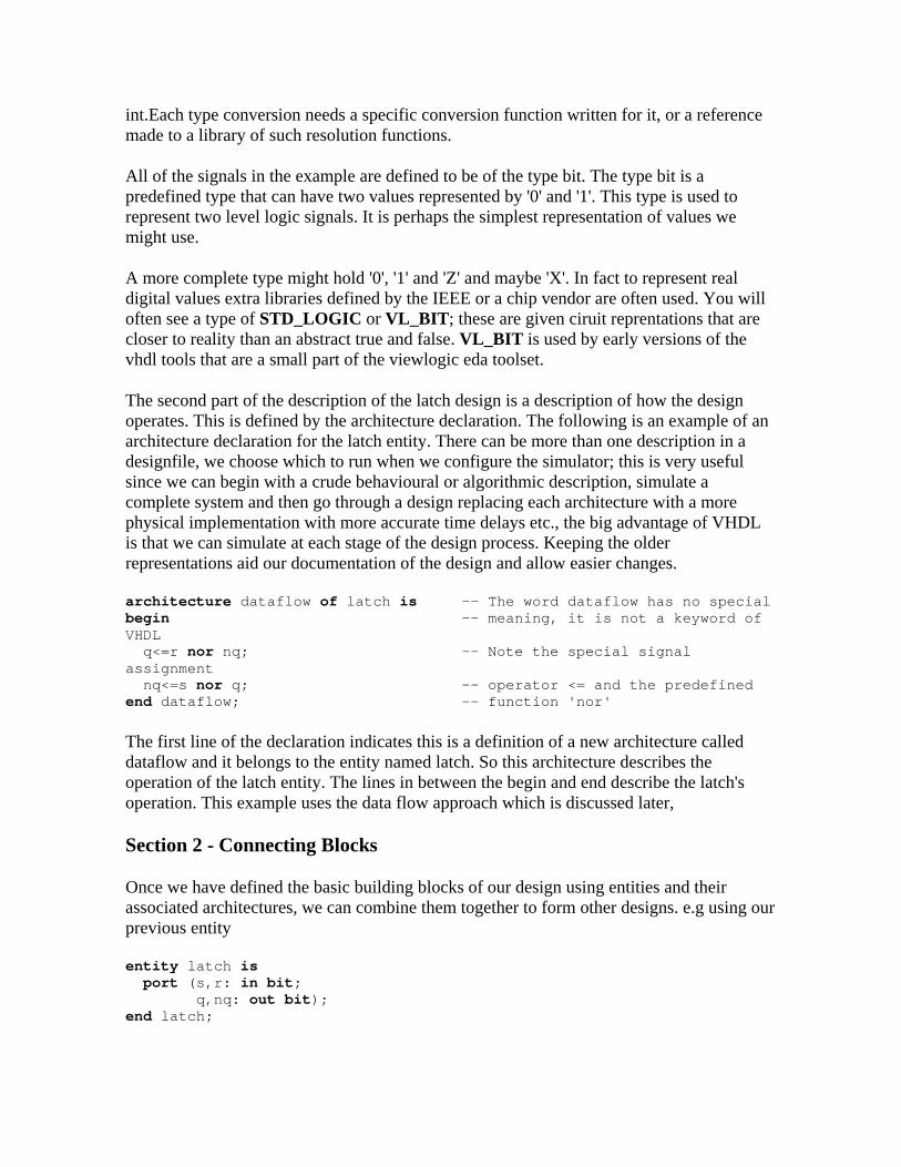
The second part of the description of the latch design is a description of how the design operates. This is defined by the architecture declaration. The following is an example of an architecture declaration for the latch entity. There can be more than one description in a designfile, we choose which to run when we configure the simulator; this is very useful since we can begin with a crude behavioural or algorithmic description, simulate a complete system and then go through a design replacing each architecture with a more physical implementation with more accurate time delays etc., the big advantage of VHDL is that we can simulate at each stage of the design process. Keeping the older representations aid our documentation of the design and allow easier changes.
architecture dataflow of latch is -- The word dataflow has no special begin -- meaning, it is not a keyword of VHDL q<=r nor nq; -- Note the special signal assignment nqend dataflow; -- function 'nor'
<=s nor q; -- operator <= and the predefined
The first line of the declaration indicates this is a definition of a new architecture called dataflow and it belongs to the entity named latch. So this architecture describes the operation of the latch entity. The lines in between the begin and end describe the latch's operation. This example uses the data flow approach which is discussed later,
Section 2 - Connecting Blocks
Once we have defined the basic building blocks of our design using entities and their associated architectures, we can combine them together to form other designs. e.g using our previous entity
entity latch is port (s,r: in bit; q,nq: out bit); end latch;
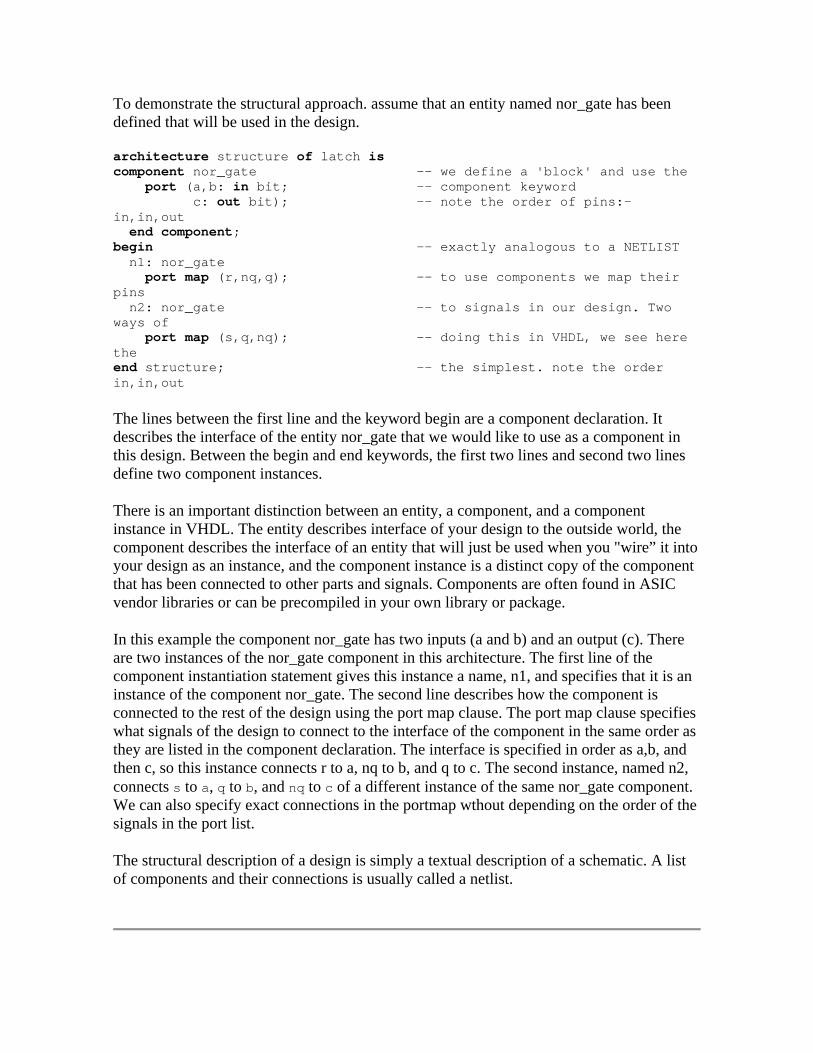
To demonstrate the structural approach. assume that an entity named nor_gate has been defined that will be used in the design.
architecture structure of latch is component nor_gate -- we define a 'block' and use the port (a,b: in bit; -- component keyword c: out bit); -- note the order of pins:- in,in,out end component; begin -- exactly analogous to a NETLIST n1: nor_gate port map (r,nq,q); -- to use components we map their pins n2: nor_gate -- to signals in our design. Two ways of port map (s,q,nq); -- doing this in VHDL, we see here the end structure; -- the simplest. note the order in,in,out
The lines between the first line and the keyword begin are a component declaration. It describes the interface of the entity nor_gate that we would like to use as a component in this design. Between the begin and end keywords, the first two lines and second two lines define two component instances.
There is an important distinction between an entity, a component, and a component instance in VHDL. The entity describes interface of your design to the outside world, the component describes the interface of an entity that will just be used when you "wire” it into your design as an instance, and the component instance is a distinct copy of the component that has been connected to other parts and signals. Components are often found in ASIC vendor libraries or can be precompiled in your own library or package.
In this example the component nor_gate has two inputs (a and b) and an output (c). There are two instances of the nor_gate component in this architecture. The first line of the component instantiation statement gives this instance a name, n1, and specifies that it is an instance of the component nor_gate. The second line describes how the component is connected to the rest of the design using the port map clause. The port map clause specifies what signals of the design to connect to the interface of the component in the same order as they are listed in the component declaration. The interface is specified in order as a,b, and then c, so this instance connects r to a, nq to b, and q to c. The second instance, named n2, connects s to a, q to b, and nq to c of a different instance of the same nor_gate component. We can also specify exact connections in the portmap wthout depending on the order of the signals in the port list.
The structural description of a design is simply a textual description of a schematic. A list of components and their connections is usually called a netlist.

DATA FLOW DESCRIPTIONS Section 1 - Dataflow Architectures
In the data flow approach, circuits are described by indicating how the inputs and outputs of built-in primitive components (ex. an and gate) or pure combinational blocks are connected together. In other words we describe how signals (data) flow through the circuit. The definition is not a formal one and textbooks differ from their approach, we might restrict ourselves to pure combinational blocks with simple single delays added between the boxes and all "control logic” put in blocks containing FSMs. or we might allow the use of registers using a single clock and no other time delays in our design at all other that the clock cycle. This would be more properly described as a RTL type of architecture. for example
entity latch is port (s,r : in bit; q,nq : out bit); end latch; architecture dataflow of latch is begin q<=r nor nq; nq<=s nor q; end dataflow;
As we saw in the last section, the entity describes the interface to the design. There are four signals s,r,q, and nq that are accessible externally to the design. Again we model the signals in our design with the VHDL data type bit, which can represent two level logic values. This is not very realistic and later we see how a more realistic data type is the special std_ulogic type defined for us in an IEEE library. It can deal with values of 'Z' or 'X' or resistive pullups and opencollector wired-or connections.
The architecture part describes the internal operation of the design. In the data flow approach we indicated how data flows from the inputs to the outputs. In VHDL this is accomplished with the signal assignment statement. The example architecture consists of two signal assignment statements.
A signal assignment statement describes how data flows from the signals on the right side of the <= operator to the signal on the left side. The first signal assignment in the example tells us that the data coming from signals r and nq flow through a nor gate to determine the value of the signal q. The nor represents a built-in component called an operator, because it operates on some data to produce new data. The second signal assignment, similar to the first, indicates that the signal nq is produced from data (s and q) flowing through (or processed by) the nor operator.
The right side of the <= operator is called an expression. The value of the expression is determined by evaluating the expression. Evaluating the expression is performed by

substituting the values of the signals in the expression and computing the result of each operator in the expression.
Section 2 - How it Works
The scheme used to model a VHDL design is called discrete event time simulation. When the value of a signal changes, we say an event has occurred on that signal. If data flows from signal A to signal B, and an event has occurred on signal A (i.e. A's value changes), then we need to determine the possibly new value of B. This is the foundation of the discrete event time simulation. The values of signals are only updated when certain events occur and events occur at discrete instances of time .
Since one event causes another, simulation proceeds in rounds. The simulator maintains a list of events that need to be processed. In each round, all events in a list are processed, any new events that are produced are placed in a separate list (and are said to be scheduled) for processing in a later round. Each signal assignment is evaluated once, when simulation begins to determine the initial value of each signal. e.g
q<=r nor nq; -- any change on r or nq causes this expression to be evaluated -- The change to q, if needed, will be 'scheduled' to happen at a nq<=s nor q; -- small finite time later, this delta time can be almost zero.
Since data flows from r and nq to q, we say that q depends on r and nq. In general, given any signal assignment statement, the signal on the left side of the <= operator depends on all the signals appearing on the right side. If a signal depends on another signal that an event has occurred on, then the expression in the signal assignment is re-evaluated. If the result of the evaluation is different than the current value of the signal, an event will be scheduled (added to the list of events to be processed) to update the signal with the new value. Thus, if an event occurs on r or nq, then the nor operator is evaluated, and if the result is different than the current value of q, then an event will be scheduled to update q.
Suppose at a particular moment during a simulation of the SR latch example, the values of the signals are s='0',r='0', q='1', and nq='0'. Now suppose the value of the signal r changes (due to some event external to the design) to the value '1'. Since q depends on r, we must re-evaluate the expression r nor nq, which now evaluates to '0'. Since the value of q must be changed to '0', a new event will be scheduled on the signal q. During the next round the event scheduled
for q is processed and q's value is updated to be '0'. Also, since nq depends on q, the expression s nor q must be re-evaluated. The result of the expression is '1', so an event is scheduled to update the value of nq. During the next round, when the event on nq is processed, the expression for q will be evaluated again because it depends on nq. However, the result of the expression will be '0' and no new event will be scheduled because q is already '0'. Since, no new events were scheduled, there are no more events that will occur internally to the latch.
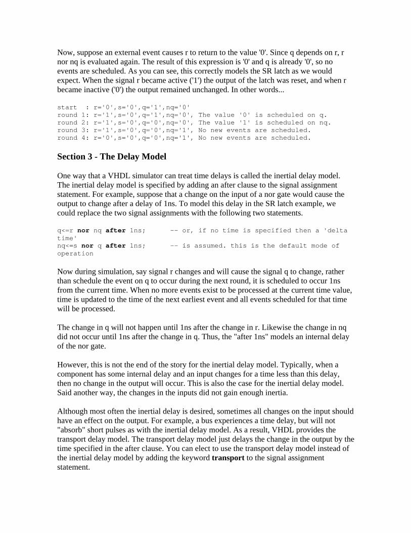
Now, suppose an external event causes r to return to the value '0'. Since q depends on r, r nor nq is evaluated again. The result of this expression is '0' and q is already '0', so no events are scheduled. As you can see, this correctly models the SR latch as we would expect. When the signal r became active ('1') the output of the latch was reset, and when r became inactive ('0') the output remained unchanged. In other words...
start : r='0',s='0',q='1',nq='0' round 1: r='1',s='0',q='1',nq='0', The value '0' is scheduled on q. round 2: r='1',s='0',q='0',nq='0', The value '1' is scheduled on nq. round 3: r='1',s='0',q='0',nq='1', No new events are scheduled. round 4: r='0',s='0',q='0',nq='1', No new events are scheduled.
Section 3 - The Delay Model
One way that a VHDL simulator can treat time delays is called the inertial delay model. The inertial delay model is specified by adding an after clause to the signal assignment statement. For example, suppose that a change on the input of a nor gate would cause the output to change after a delay of 1ns. To model this delay in the SR latch example, we could replace the two signal assignments with the following two statements.
q<=r nor nq after 1ns; -- or, if no time is specified then a 'delta time' nq<=s nor q after 1ns; -- is assumed. this is the default mode of operation
Now during simulation, say signal r changes and will cause the signal q to change, rather than schedule the event on q to occur during the next round, it is scheduled to occur 1ns from the current time. When no more events exist to be processed at the current time value, time is updated to the time of the next earliest event and all events scheduled for that time will be processed.
The change in q will not happen until 1ns after the change in r. Likewise the change in nq did not occur until 1ns after the change in q. Thus, the "after 1ns" models an internal delay of the nor gate.
However, this is not the end of the story for the inertial delay model. Typically, when a component has some internal delay and an input changes for a time less than this delay, then no change in the output will occur. This is also the case for the inertial delay model. Said another way, the changes in the inputs did not gain enough inertia.
Although most often the inertial delay is desired, sometimes all changes on the input should have an effect on the output. For example, a bus experiences a time delay, but will not "absorb" short pulses as with the inertial delay model. As a result, VHDL provides the transport delay model. The transport delay model just delays the change in the output by the time specified in the after clause. You can elect to use the transport delay model instead of the inertial delay model by adding the keyword transport to the signal assignment statement.

q <= transport r nor nq after 1ns; -- now any short pulses on r or nq nq <= transport s nor q after 1ns; -- will apear on q, and hence to nq 2 ns later
Section 4 - Other Types
In the previous sections all of the signals in the examples have been of the type bit. VHDL provides several other types, some of which are described here. Often we use several bit signals together to represent a binary number in a design. VHDL provides a mechanism for defining new types which represent a collection of several data items of the same type. These kinds of types are called arrays. There is a predefined array type called bit_vector which represents a collection of bits. The following example demonstrates how the bit_vector type can be used to define a 1-to-4-line demultiplexer.
entity demux is port (e: in bit_vector (3 downto 0); -- enables for each output s: in it_vector (1 downto ); -- select signals b 0 d: out bit_vector (3 downto 0)); -- four output signals end demux; architecture rtl of demux is signal t : bit_vector(3 downto 0); -- an internal signal not visible begin -- outside the entity t(3)<=s(1) and s(0); -- assign each element in turn t(2)<=s(1) and not s(0); t(1)<=not s(1) and s(0); t(0)<=not s(1) and not s(0); d<=e and t; -- or assign a complete bit_vector end rtl; -- nb VHDL is VERY fussy about types
When operations are performed on whole vectors, the vectors must have the same number of elements. If they do not, the simulator will report an error and stop the simulation. In an operation between vectors, elements are matched as they are number from left to right. Thus, if a variable v1 has elements 0 to 1 and variable v2 has elements 1 downto 0. Then
v1:=v2; -- this assign the variable v2(1) to v1(0) and v2(0) to v1(1). -- we meet variables later, note the use of := instead of <=
Another predefined type is time. We have already used constant values of this type in the after clause. Time is an example of a physical type. All values of a physical type have two parts, a number and a unit name. The type time includes the following predefined unit names sec (seconds), ms (milliseconds), us (microseconds), ns (nanoseconds), ps (picoseconds), and fs (femtoseconds). There are several other types predefined in VHDL including types for integers and real numbers and you can define your own types, subtypes and aliases.

Section 5 - Other Operators
The logical operators NOT, AND, OR, NAND, NOR, and XOR can be used with any bit type or bit_vector. When used as operators on bits they have their usual meaning. When used with bit_vectors, the bit_vectors must have the same number of elements, and the operation is performed bitwise. For example, "00101001" xor "1110101" results in "11001100".
note: just as '0' and '1' represent constant bit values, constant bit_vectors can be written in VHDL as a list of bit values in double quotes. e.g
d<="1100"; --Hexadecimal can also be used by use of a X prefix d<=X"C"; -- has the same effect as the line above
The typical algebraic operators are available for integers, such as +,-,* and /. Although these operations are not built-in for bit_vectors, they are often provided in libraries that come with your VHDL software. They are used with bit_vectors by interpreting them as a binary representation of integers, which may be added, subtracted, multiplied, or divided.
Also predefined are the normal relational operators. They are =, /=,<, <=, > and >= and have their usual meanings (/= is the not equal operator). The result of all these operators is a boolean value (TRUE or FALSE). The arguments to the = and /= operators may be of any type. The arguments of the <, <=, > and >= operators may be any scalar type (integer, real, and physical types) or the bit_vector type. If the arguments are bit_vectors, then the arguments must be the same length and the result is TRUE only if the relation is true for each corresponding element of the array arguments.
The & operator is a built-in VHDL operator that performs the concatenation of bit_vectors. For example, with the following declarations:
signal a: bit_vector (1 to 4); signal b: bit_vector (1 to 8); The following statement would connect a to the right half of b and make the left half of b constant '0'. b<="0000" & a;
The & appends the a to the end of the "0000" to form a result that has 8 bits.
BEHAVIOURAL DESCRIPTIONS
Section 1 - The Process Statement

The behavioural approach to modeling hardware components is different from the other two methods in that it does not necessarily in any way reflect how the design is implemented. It is basically the black box approach to modeling. It accurately models what happens on the inputs and outputs of the black box, but what is inside the box (how it works) is irrelevant. The behavioral description is usually used in two ways in VHDL. First, it can be used to model complex components that would be tedious to model using the other methods. This might be the case for example, if you wish to simulate the operation of your custom design connected to a commercial part like a microprocessor. In this case, the microprocessor is complex and its internal operation is irrelevant (only the external behavior is important) so it would probably be modeled using the behavioral style. Second, the behavioral capabilities of VHDL can be more powerful and is more convenient for some designs. In this case the behavioral description will likely imply some structure of the implementation. Also in the early part of the design process you can use behavioural models to quickly evaluate an algorithm and simulate it by pasing real data through it. Alternatively if youadopt a top-down approach you can leave each block in your block diagram with a working behavioural model until it can be implemented structurally. Lastly note that there is a trend to use synthesis tools to automate the conversion of behavioural to structural, with restraints on the target techgnology and the behavioural style then being necessary.
Behavioral descriptions are supported with the process statement. The process statement can appear in the body of an architecture declaration just as the signal assignment statement does. The contents of the process statement can include sequential statements like those found in software programming languages. These statements are used to compute the outputs of the process from its inputs. Sequential statements are often more powerful, but sometimes have no direct correspondence to a hardware implementation. The process statement can also contain signal assignments in order to specify the outputs of the process.
A group of processes will be executed concurrently since the process is a concurrent statement, it usually contains sequential ststements. We can also group a block of concurrent statements together and specify when they are to be executed. This can be efficient but is not needed for the uses of VHDL given in this handout.
Our first example of the process statement is trivial and would not normally be done in a process statement. However, it allows us to examine the process statement without learning any sequential statements first.
compute_xor: process (b,c) -- we can name processes if we wish (it’s optional) begin -- note we list the signals that the process a<=b xor c; -- depends on. The proces will only execute end process; -- when a change occurs on b or c (or at power on) -- we call (b,c) the sensitivity list
This example process contains one statement, the signal assignment. Unlike signal assignments that appear outside the process statement, this signal assignment is only evaluated when events occur on the signals in the process' sensitivity list, regardless of

which signals appear on the right side of the <= operators. This means it is critical to make sure the proper signals are in the sensitivity list.
The statements in the body of the process are performed (or executed) in order from first to last. When the last statement has been executed the process is finished and is said to be suspended. When an event occurs on a signal in the sensitivity list, the process is said to be resumed and the statements will be executed from top to bottom again. Each process is executed once during the beginning of a simulation to determine the initial values of its outputs.
Section 2 - Using Variables
There are two major kinds of objects used to hold data. The signal is used mostly in structural and data flow descriptions and used to "connect” two processes together. The second can only be used in processes and is called a variable. It behaves as you would expect in a software programming language, which is much different than the behavior of a signal.
a:=b;
This variable assignment assigns the value of b to a. The value is simply copied to a immediately. Since variables may only be used in processes, the assignment statement may only appear in a process. The assignment is performed when the process is executed, as explained in the last section.
count: process (x) -- executed at powerup then idles unitl x changes variable cnt : integer := -1; -- Initialisation is only done at
up power begin cnt:=cnt+1; --cnt will hold its value between executions end process;
Variable declarations appear before the begin keyword of a process statement as in the example. The variable declaration is the same as the signal declaration except the key word variable is used instead of signal. The declaration in this example includes an optional part, which specifies the initial value of the variable, when a simulation begins. The initialization part is included by adding the := and some constant expression after the type part of the declaration. This initialization part may also be included in signal declarations. The variable cnt is declared to be of the type integer. The integer type represents negative and positive integer values.
The process in the example contains one statement, the assignement statement. This assignment computes the value of cnt plus one and immediately stores that new value in the variable cnt. Thus, cnt will be incremented by one each time this process is executed. Since the value is initialized to -1, and the process is executed once before beginning simulation, the value of cnt will be 0 when simulation begins. Once simulation begins, cnt will be

incremented by one each time the signal x changes. If x is a bit signal, then this process will count the number of rising and falling edges that occur on the signal x.
Section 3 - Sequential Statements
There are several statements that may only be used in the body of a process. These statements are called sequential statements because they are executed sequentially. That is, one after the other as they appear in the design from the top of the process body to the bottom. In this section we will examine some of these statements. See the reference manual for further details on if and for loops
One form of the if statement and a common use of VHDL attributes .
count: process (x) variable cnt : integer :=0 ; begin -- note the ‘attribute below if (x='1' and x'last_value='0') then -- the expression must evaluate to cnt:=cnt+1; -- to TRUE or FALSE, ‘1’ or ‘0’ end if; end process;
Attributes can be used to obtain a lot of auxiliary information about signals. The if statement will only be executed when an event has occurred on x (i.e. x has just changed), this condition will be true when a rising edge occurs on x. This is because we know x just changed, we know it was a '0' and now it is a '1'. Thus, the assignment statement in this example is executed every time there is a rising edge on the signal x, counting the number of rising edges.
The loop statement. There are several varients; one form of the loop statement, is called a for statement. The following example uses a loop statement to compute the even parity of a bit vector.
signal x : bit_vector (7 downto 0); ... process (x) begin variable p : bit;
p:='0' for i in downto 0 loop 7
p:=p xor x(i); end loop; end process;
The first part of the for loop i in 7 downto 0 is called the parameter specification. It specifies how many times the loop body will be executed and creates a temporary variable. It begins with the name of the temporary variable that will be created, in this case it is i. This is followed by the key word in and then a range of values as we have seen before. The body of the loop is executed once for every value in the range specified. The value of the temporary variable is assigned one of the values in the range each time the loop body is

executed. In this example, the assignment will be executed first with i=7 then again with i=6, and again with i=5, and so on down to 0.
Section 4 - Signals and Processes
This section is short, but contains important information about the use of signals in the process statement. Remember a signal assignment, if anything, merely schedules an event to occur on a signal and does not have an immediate effect. When a process is resumed, it executes from top to bottom and no events are processed until after the process is complete. This means, if an event is scheduled on a signal during the execution of a process, that event can be processed after the process has completed at the earliest. Be careful if using more than one signal ssignment per process!
... signal x,y,z : bit; ... process -- a change on y triggers the proces to execute (y) begin -- (actually adding x and z to the sensitivity list -- can avoid some of the pitfals below, and create others) x<=y; -- A signal change scheduled to occur after process executed z<=not x; -- So it is the old value of x that will be scheduled here end process; -- usually better to add explicit 1ns delays on all signals
This is pointed out because this is not necessarily the intuitive behavior and because variables operate differently. For example, in
process (y) -- variable x,z : bit; begin x:=y; -- x changed immediately then we move sequentially onward z:=not x; -- z will always be the opposite of y end process;
Section 5 - Program Output
In most programming languages there is a mechanism for printing text on the monitor and getting input from the user through the keyboard, it is also nice to be able to output certain information during simulation. This is not provided as a language feature in VHDL, but rather as a standard library that comes with every VHDL language system. In VHDL, common code can be put in a separate file to be used by many designs. This common code is called a library. In order to use the library that provides input and output capabilities you must add the statement
use textio.all;

immediately before every architecture that uses input and output. The name of the library is textio and this statement indicates that you wish to use everything or all of the textio library. Once you have done that, you may use any of the features discussed in this section. Note that although it is not part of the language, the library is standard and will be the same regardless of the VHDL tools you are using.
Text is input and output using textio via a variable of the type line. Since variables are used for textio, input and output is done in processes. The procedure for outputting information is to first place it in text form into the variable of type line and then to request that the line be output. This is shown in the following example.
use textio.all; architecture behavior of check is begin process (x) variable s : line; variable cnt : integer:=0; begin if (x='1' and x'last_value='0') then cnt:=cnt+1; if (cnt>MAX_COUNT) then write(s,"Count overflow - ");--appends to the end of the line variable write(s,cnt); -- which is initialised to empty writeline(output,s); -- outputs the line variable to the screen and end if; -- empties is for reuse. end if; end process; end behavior;
If MAX_COUNT were a constant equal to 15 and more than 15 rising edges occur on the signal x, then the message
Counter overflow - 16
would be printed on the screen.
Section 6 - Program input
Using a disk file to read in data can also be very useful and can supplement the usually very powerful features of most simulators in providing stimulis input for simulation runs. For example if testing a CPU or a digital system working on a stream of input data, we could write a C program to generate a input disk file which could then be input to the VHDL model and its output analysed, either on the screen or by having the VHDL write its computed output to a diskfile. This can then be imported into a C program or even a spreadsheet or wordprocessing program and tested there. Examples of this approach can be seen in some CPU models were an assembler produces an object code file to be "fed” to the VHDL model of the CPU. One of the SPARC CPUs had its monitor firmware debugged this way before working silicon was available from the foundry.

Further resources The vhdl cookbook and the VHDL files repositories mentioned in the VHDL FAQs on the internet can provide much extra material. Some of these are held on the WEB server HTTP://www.eej.ulst.ac.uk