A SIMULATION ACCESS LANGUAGE AND FRAMEWORK WITH...
205
A SIMULATION ACCESS LANGUAGE AND FRAMEWORK WITH APPLICATIONS TO PROJECT MANAGEMENT A DISSERTATION SUBMITTED TO THE DEPARTMENT OF CIVIL AND ENVIRONMENTAL ENGINEERING AND THE COMMITTEE ON GRADUATE STUDIES OF STANFORD UNIVERSITY IN PARTIAL FULFILLMENT OF THE REQUIREMENTS FOR THE DEGREE OF DOCTOR OF PHILOSOPHY Jinxing Cheng August 2004
Transcript of A SIMULATION ACCESS LANGUAGE AND FRAMEWORK WITH...

A SIMULATION ACCESS LANGUAGE AND FRAMEWORK WITH APPLICATIONS TO PROJECT MANAGEMENT
A DISSERTATION
SUBMITTED TO THE DEPARTMENT OF
CIVIL AND ENVIRONMENTAL ENGINEERING
AND THE COMMITTEE ON GRADUATE STUDIES
OF STANFORD UNIVERSITY
IN PARTIAL FULFILLMENT OF THE REQUIREMENTS
FOR THE DEGREE OF
DOCTOR OF PHILOSOPHY
Jinxing Cheng
August 2004

ii
Copyright by Jinxing Cheng 2004
All Rights Reserved

iii
I certify that I have read this dissertation and that, in my opinion, it is fully adequate in scope and quality as a dissertation for the degree of Doctor of Philosophy.
__________________________________ Kincho H. Law
(Principal Advisor)
I certify that I have read this dissertation and that, in my opinion, it is fully adequate in scope and quality as a dissertation for the degree of Doctor of Philosophy.
__________________________________ Gio Wiederhold
I certify that I have read this dissertation and that, in my opinion, it is fully adequate in scope and quality as a dissertation for the degree of Doctor of Philosophy.
__________________________________ Hans Björnsson
Approved for the University Committee on Graduate Studies.

iv
Abstract
As computer programs become ever more complex, software development has shifted
from focusing on programming towards focusing on integration. This trend is also seen
in the design and construction industry, where there is an increasing need to integrate and
reuse commercial software tools. Although many software applications (e.g., Microsoft
Project, Microsoft Excel, the Primavera Project Planner, and AutoCAD) are commonly
available for construction engineering and project management, it remains a laborious
process to integrate and coordinate these tools to work together and to support decision
making. To name a few, the sheer volume and complexity of the tools and the
information generated by them, their scattered distribution, and the lack of
interoperability are among the challenges in integrating, coordinating, and reusing these
tools.
This thesis first discusses the potential applications of the Process Specification
Language (PSL) for project management applications. Initiated by the National Institute
of Standards and Technology (NIST), PSL is emerging as a standard exchange language
for process information in the manufacturing industry. This thesis discusses how PSL
can be used for exchanging information among project management software
applications in the construction industry. The potential applications of PSL in
consistency checking and constraint scheduling are also explored. Specifically, a formal
mechanism is proposed to perform consistency checking on project information from

v
different computer tools. Furthermore, the use of PSL for checking conformity of project
schedules to scheduling constraints is illustrated.
This thesis presents a simulation access language (SimAL) and framework for project
management applications. The SimAL language and framework integrate legacy project
management applications, coordinate different tools, manage the information flow among
them, and bring their functionalities online. The prototype of the SimAL framework has
been implemented based on PSL for data exchange and a flow-based software
composition infrastructure for software integration. Using the prototype, users can
simulate scenarios and build up new services from the existing tools.
The potential applications of the SimAL language and framework are demonstrated using
three illustrative examples. This first example illustrates the use of SimAL to incorporate
online information in project management. The second example illustrates how to use
SimAL to compare different scenarios in project management. The third example
demonstrates how to extend the functions of legacy software applications (e.g., AutoCAD
ADT and the Primavera Project Planner) by integrating them to provide new services.
Finally, this thesis presents a question answering system to query the information in
different project management applications. A prototype question answering system has
been built and tested to illustrate the potential usefulness of such a system for project
management applications.

vi
Acknowledgments
There have been a great number of truly exceptional people who contributed to my
research and social life at Stanford University.
First and foremost, I wish to express my profound gratitude to Prof. Kincho H. Law, my
advisor and mentor, for his constant support and encouragement. I am privileged to have
the opportunity to share his passion for research and his insights in life. I would like to
extend my gratitude to my dissertation reading committee, Prof. Gio Wiederhold and
Prof. Hans Björnsson, for their invaluable advice, criticism, and recommendations. I also
want to thank Prof. Ozalp Ozer for chairing my oral defense and Dr. Renate Fruchter for
serving on my defense committee on short notice.
I would like to thank my family and friends. Without their support and encouragement, I
never would have made it to Stanford. Their support over the past several years helped
sustain me through the ups and downs of conducting research work. I am very lucky to
have such a wonderful supportive family and great friends.
Many other people contributed to the development of this research. I would like to thank
Professor Bimal Kumar of Glasgow Caledonian University for his support on the
collaborative demonstration of the simulation access framework and his contribution to
the question answering system, Dr. Michael Gruninger and Dr. Ram D. Sriram of NIST
for their contribution to the PSL research work, and Dr. David Liu for his contribution to

vii
the distributed integration framework. I would also like to thank the following
companies and individuals for providing the data used in my research: Webcor Builders,
Swinerton Builders, DPR Construction Inc., and Professor Martin Fischer and his
research group at Stanford University.
I am grateful to the members of the EIG (Engineering Informatics Group), including Jun
Peng, Jerome Lynch, Jie Wang, Chuck Han, Shawn Kerrigan, Gloria Lau, Charles
Heenan, Li Zhang, Liang Zhou, Bill Labiosa, Yang Wang, Haoyi Wang, Xiaoshan Pan,
Arvind Sundararajan, and Pooja Trivedi, for helping me with various aspects of my
research and life. They make the research group truly like a home to me.
I gratefully acknowledge the financial support provided by the Center for Integrated
Facility Engineering at Stanford University, the Product Engineering Program at National
Institute of Standards and Technology, and a Stanford Graduate Fellowship.

viii
Table of Contents
Abstract iv
Acknowledgments vi
List of Tables xiii
List of Figures xiv
1 Introduction 1
1.1 Motivation ........................................................................................................ 1
1.2 Research Objective........................................................................................... 4
1.3 Related Research .............................................................................................. 5
1.3.1 Data Integration and Exchange............................................................... 5
1.3.2 Software Integration and Interoperability............................................... 9
1.4 Thesis Outline................................................................................................. 14
2 The Process Specification Language (PSL) for Project Management
Applications 16
2.1 Overview of PSL............................................................................................ 17
2.2 Using PSL to Exchange Information among Project Management
Applications.................................................................................................... 21
2.2.1 Semantic Mapping between PSL and Project Management
Application Concepts............................................................................ 21
2.2.2 Wrapping Project Management Applications....................................... 27

ix
2.3 Distributed Data Integration Infrastructure .................................................... 35
2.3.1 Translation between PSL and Database................................................ 36
2.3.2 Network Communication in the Distributed Integration Framework... 38
2.4 Demonstrations of Distributed Data Integration ............................................ 39
2.4.1 Example 1: A Chip Design Scenario .................................................... 40
2.4.2 Example 2: Mortenson Ceiling Project................................................. 43
2.5 PSL for Consistency Checking....................................................................... 46
2.5.1 Conflicts in Project Management ......................................................... 46
2.5.2 Review of Existing Approaches in Conflict Resolution....................... 47
2.5.3 Consistency Checking using PSL......................................................... 48
2.5.4 Demonstration of the Consistency Checking Prototype ....................... 51
2.5.5 Soundness and Completeness ............................................................... 56
2.5.6 Performance Analysis of Consistency Checking.................................. 58
2.6 PSL for Constraint Scheduling....................................................................... 60
2.6.1 Scheduling Constraint Categorization and Expression......................... 60
2.6.2 PSL for Constraint Scheduling ............................................................. 63
2.7 Summary ........................................................................................................ 66
3 A Simulation Access Language (SimAL) and Framework 68
3.1 Overview of the Simulation Framework ........................................................ 69
3.2 A Brief Review of FICAS.............................................................................. 71
3.3 The SimAL Access Language (SimAL) ........................................................ 75
3.3.1 The Design Goal of the SimAL Language ........................................... 75
3.3.2 The Components of the SimAL Language ........................................... 77
3.3.2.1 Invocation Statements............................................................. 78
3.3.2.2 Operation Statements.............................................................. 79
3.3.2.3 Decision-Support Statements.................................................. 81
3.3.2.4 Control Statements.................................................................. 83
3.4 The SimAL Language Specification and Compiler ....................................... 85
3.4.1 SimAL Syntax and Definitions............................................................. 85

x
3.4.2 The SimAL Compiler ........................................................................... 89
3.5 Comparison Between CLAS and SimAL....................................................... 92
3.6 The SimAL Framework.................................................................................. 93
3.6.1 Project Management Applications and Wrappers ................................ 95
3.6.2 SimAL Preprocessing Engine ............................................................... 99
3.6.3 The Update and Query Engine............................................................ 101
3.6.3.1 Translation Between PSL and ifcXML ................................ 102
3.6.3.2 Querying and Updating Information .................................... 107
3.6.4 SimAL Post-Processing Engine.......................................................... 108
3.7 Demonstration of the SimAL System .......................................................... 108
3.8 Summary ...................................................................................................... 111
4 Simulation Framework for Project Management Applications 112
4.1 Using SimAL to Incorporate Weather Information ..................................... 113
4.1.1 Expressing Weather Information in XML.......................................... 113
4.1.2 Expressing the Knowledge of Weather Impact in XML .................... 115
4.1.3 Processing Weather Information ........................................................ 116
4.1.4 Demonstration Example – Simulating the Impact of Weather in
Project Management ........................................................................... 117
4.2 Using SimAL to Compare Schedule Recovery Options .............................. 123
4.2.1 The McDonald Housing Expansion Project ....................................... 124
4.2.2 Using SimAL to Simulate and Compare Alternatives........................ 127
4.3 Using SimAL to View Construction Progress ............................................. 133
4.4 Summary ...................................................................................................... 139
5 A Question Answering System for Project Management Applications 140
5.1 Introduction .................................................................................................. 141
5.2 Related Technologies ................................................................................... 143
5.2.1 XML Query Language........................................................................ 144
5.2.2 XML Query Engine ............................................................................ 144
5.2.3 POS Tagging and Chart Parsing Tools ............................................... 145

xi
5.2.4 WordNet.............................................................................................. 145
5.3 Knowledge Representation and Organization in QAPM ............................. 146
5.3.1 Knowledge Representation using ifcXML ......................................... 146
5.3.2 Knowledge Organization .................................................................... 147
5.4 Parsing and Understanding Natural Questions............................................. 149
5.4.1 Analyzing ifcXML Trees.................................................................... 149
5.4.2 Tagging Questions .............................................................................. 152
5.4.3 Parsing Questions ............................................................................... 152
5.4.4 Analyzing Concepts and Matching Rules........................................... 155
5.5 Searching for Answers in the Knowledge Base ........................................... 157
5.6 Answer Generation....................................................................................... 158
5.7 The Framework and Implementation of QAPM .......................................... 159
5.8 Sample Demonstration of QAPM ................................................................ 162
5.8.1 Example Project used in the Demonstration....................................... 162
5.8.2 Working Scenario ............................................................................... 165
5.8.3 Analysis of the Results ....................................................................... 168
5.9 Summary and Discussions............................................................................ 169
6 Summary and Discussions 170
6.1 Summary and Contributions......................................................................... 170
6.2 Future Research............................................................................................ 172
6.2.1 The Process Specification Language (PSL)........................................ 172
6.2.1.1 Exchanging Product and Process Information...................... 172
6.2.1.2 Constraint Scheduling using PSL ......................................... 174
6.2.2 The Simulation Access Language (SimAL) and Framework ............. 174
6.2.2.1 Decision-Support Capabilities of SimAL............................. 174
6.2.2.2 Computational Capabilities of SimAL ................................. 174
6.2.2.3 Validation and Testing.......................................................... 175
6.2.3 The Question Answering System ....................................................... 175
6.3 Conclusions .................................................................................................. 176

xii
Bibliography 177
xiii
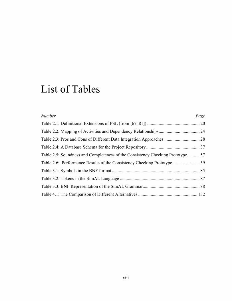
List of Tables
Number Page Table 2.1: Definitional Extensions of PSL (from [67, 81]) .............................................. 20
Table 2.2: Mapping of Activities and Dependency Relationships.................................... 24
Table 2.3: Pros and Cons of Different Data Integration Approaches ............................... 28
Table 2.4: A Database Schema for the Project Repository............................................... 37
Table 2.5: Soundness and Completeness of the Consistency Checking Prototype........... 57
Table 2.6: Performance Results of the Consistency Checking Prototype........................ 59
Table 3.1: Symbols in the BNF format ............................................................................. 85
Table 3.2: Tokens in the SimAL Language ...................................................................... 87
Table 3.3: BNF Representation of the SimAL Grammar.................................................. 88
Table 4.1: The Comparison of Different Alternatives .................................................... 132

xiv
List of Figures
Number Page Figure 1.1: The Trend of Software Development (from [98]) ........................................... 1
Figure 1.2: Applications in Construction Project Management.......................................... 3
Figure 2.1: Core Theories of the PSL Ontology (from [67, 81]) ...................................... 18
Figure 2.2: Dependency Relationships among Activities ................................................. 23
Figure 2.3: Example Dependency of a Scheduling Chart in Primavera P3 ...................... 26
Figure 2.4: Schedule and Resource Information from Primavera P3 ............................... 27
Figure 2.5: PSL Expressions for the Example Chart in Primavera P3.............................. 27
Figure 2.6: PSL Wrappers................................................................................................. 31
Figure 2.7: The Decomposition of PSL Wrappers........................................................... 33
Figure 2.8: Exchange Information between Primavera P3 and Vite SimVision through
PSL.................................................................................................................. 34
Figure 2.9: A Distributed Integration Infrastructure ......................................................... 36
Figure 2.10: Translation between Database and PSL ....................................................... 38
Figure 2.11: A Network Communication Framework ...................................................... 39
Figure 2.12: The Code Segment of an Event Listener ...................................................... 39
Figure 2.13: Original CPM Diagram in Vite SimVision .................................................. 41
Figure 2.14: Sample PSL File ........................................................................................... 41
Figure 2.15: Original Gantt Chart in Vite SimVision ....................................................... 42
Figure 2.16: Regenerated Schedule in Primavera P3 using PSL ...................................... 42

xv
Figure 2.17: Regenerated Schedule in Microsoft Project using PSL................................ 42
Figure 2.18: Original Schedule in Primavera P3............................................................... 44
Figure 2.19: Model in 4D Viewer Taken on March 25, 2001........................................... 44
Figure 2.20: Regenerated Gantt Chart in Microsoft Project using PSL............................ 44
Figure 2.21: Updated Project Schedule in Microsoft Project............................................ 45
Figure 2.22: Updated Project Schedule in Primavera P3 .................................................. 45
Figure 2.23: Updated Model in 4D Viewer Taken on March 25, 2001 ............................ 45
Figure 2.24: Consistency Checking using PSL................................................................. 49
Figure 2.25: Converting PSL Expressions into Otter Input .............................................. 50
Figure 2.26: Simplified Reasoning Process in Otter ......................................................... 50
Figure 2.27: Group 1’s Schedule in Primavera P3........................................................... 52
Figure 2.28: Group 1’s CPM Diagram.............................................................................. 52
Figure 2.29: Group 2’s Schedule in Microsoft Project ..................................................... 52
Figure 2.30: Group 2’s CPM Diagram.............................................................................. 53
Figure 2.31: Reasoning Results in Cyclic Dependency Relationships ............................. 54
Figure 2.32: Cycle in Dependency Relationships ............................................................. 54
Figure 2.33: Reasoning Results in Version Conflicts ....................................................... 55
Figure 2.34: An Example Schedule .................................................................................. 64
Figure 2.35: The Scheduling Information Expressed in PSL .......................................... 64
Figure 3.1: Conceptual Model of the SimAL System....................................................... 70
Figure 3.2: FICAS Architecture (from [62])..................................................................... 72
Figure 3.3: Sample Code in CLAS.................................................................................... 72
Figure 3.4: Comparison Between FICAS and SOAP on Local Area Network (from
[62])................................................................................................................. 74
Figure 3.5: Example Program for Testing the SimAL Language ..................................... 89
Figure 3.6: SimAL Sequence Generated from the Example Program .............................. 91
Figure 3.7: The SimAL Framework.................................................................................. 94
Figure 3.8: Service Directory............................................................................................ 97
Figure 3.9: The Invocation of Embedded and Standalone Services ................................. 98

xvi
Figure 3.10: An Example Event Message......................................................................... 98
Figure 3.11: XML Information for Displaying Results .................................................. 100
Figure 3.12: The Implementation of the SimAL Query and Update Engine .................. 102
Figure 3.13: Mapping Process between PSL and XML.................................................. 106
Figure 3.14: Sample PSL File ......................................................................................... 106
Figure 3.15: Sample ifcXML file.................................................................................... 106
Figure 3.16: An Example SimAL Program..................................................................... 110
Figure 3.17: Viewing the Schedule Changes on a Web Browser ................................... 110
Figure 3.18: Viewing the Schedule Changes in Microsoft Excel ................................... 111
Figure 4.1: Expressing Weather Information in XML.................................................... 114
Figure 4.2: Expressing the Impact of Weather in XML.................................................. 115
Figure 4.3: Original and Updated Schedules in PSL ...................................................... 116
Figure 4.4: Processing the Impact of Weather ................................................................ 117
Figure 4.5: The Input of the SimAL System................................................................... 118
Figure 4.6: The Workflow in the Weather Demonstration ............................................. 119
Figure 4.7: Original Schedule in Primavera P3 .............................................................. 120
Figure 4.8: Updated Schedule in Primavera P3 .............................................................. 121
Figure 4.9: Original Backlogs in Chart ........................................................................... 121
Figure 4.10: Updated Backlogs in Chart ......................................................................... 122
Figure 4.11: Original Backlogs in Table......................................................................... 122
Figure 4.12: Updated Backlogs in Table......................................................................... 123
Figure 4.13: The 3D Model of the Project ...................................................................... 124
Figure 4.14: The Detailed Schedule of the Ronald Mcdonald House Project ................ 125
Figure 4.15: The Executive Schedule Reproduced in Primavera P3 .............................. 126
Figure 4.16: Cost Estimating of the Project .................................................................... 127
Figure 4.17: Using SimAL to Simulate Schedule Recovery........................................... 129
Figure 4.18: The Schedule Recovery Process................................................................. 130
Figure 4.19: The Result of Comparing Three Options.................................................... 132
Figure 4.20: Update CAD Models .................................................................................. 134

xvii
Figure 4.21: View the CAD Model on July 15th, 2003 on a Web Browser .................. 135
Figure 4.22: View the CAD Model on November 20th, 2003 on a Web Browser ........ 136
Figure 4.23: Visualize the Impact of Schedule Change .................................................. 137
Figure 4.24: Visualize the Schedule Change on a Web Browser.................................... 138
Figure 4.25: Visualize the Results in Primavera P3........................................................ 138
Figure 4.26: Visualize the Model Change in AutoCAD ADT........................................ 138
Figure 4.27: Visualize the Model Change on a Web Browser........................................ 139
Figure 5.1: A Context Tree For Knowledge Organization.............................................. 148
Figure 5.2: Tree Structure of IfcXML Files.................................................................... 150
Figure 5.3: Grammar File for the System ....................................................................... 153
Figure 5.4: Tagging and Parsing Questions .................................................................... 154
Figure 5.5: Preparing A Lexicon File.............................................................................. 155
Figure 5.6: Parse Tree of A Sample Question................................................................. 155
Figure 5.7: The Framework of QAPM............................................................................ 160
Figure 5.8: Detailed Process of the QAPM Question Answering System...................... 161
Figure 5.9: The Gant Chart of the Chip Design Project in Primavera P3 ....................... 162
Figure 5.10: Generated Sample ifcXML File from Primavera P3 .................................. 163
Figure 5.11: The Chip Design Project in Vite SimVision .............................................. 164
Figure 6.1: Typical Process Information in Project Management .................................. 173

Chapter 1
Introduction
1.1 Motivation
As computer programs become ever more complex, software development has shifted
from focusing on coding toward focusing on integration, as illustrated in Figure 1.1 [98].
In parallel to this trend, there is another shift of software development from standalone
applications toward distributed, Web-based or Web-enabled services. As a result, future
software will be based more and more on the composition and integration of existing
software components.
Coding
Integration
1970 1990 2010
Figure 1.1: The Trend of Software Development (from [98])

CHAPTER 1. INTRODUCTION 2
Let us take the project management field in the construction industry as an example.
There are many software tools (e.g., Microsoft Project, Microsoft Excel, the Primavera
Project Planner, and AutoCAD) that are commonly available for construction engineering
and project management. These standalone application tools are mature and widely
adopted. However, integrating and coordinating these tools to work together and to
support decision making remains a laborious process. As an example, resource
discrepancy occurs frequently in construction project management. When procurement is
being delayed, what options are available and which option is the most appropriate to
recover the lost time? Should human resources be added to accelerate the remaining
tasks or should extra fees be spent to expedite the delivery? What adjustments are
necessary for each option? When making a decision, we also have to consider the
potential impacts on project schedules, costs, resources, and organization. To simulate
possible impacts and to support decision making would involve using different tools. As
illustrated in Figure 1.2, one may use the Primavera Project Planner (P3) or Microsoft
Project to schedule the project, Vite SimVision to simulate project organization,
Timberline’s Precision Estimating to estimate project cost, and 4D Viewer [66] or other
CAD tools to view the models. A framework that would allow dynamically integrating
and coordinating application tools to simulate the impact of resource allocation on a
project and to review “what-if” scenarios can significantly enhance the decision-making
process.

CHAPTER 1. INTRODUCTION 3
AutoCADADT
MS Project
MS EXCEL
4D Viewer
CostWorksViteSimVision
Timberline
PrimaveraP3
Desktop PC
Server
Laptop
PDA
RFI'sSubmittals Online Information
( e.g., Weather Forecastingand Price Quoting)
Figure 1.2: Applications in Construction Project Management
Among the key issues for integrating and coordinating application tools for simulation is
the issue of data and software interoperability. It is not unusual that project data is being
re-entered from one application to another. Typical engineering and project management
application tools generate large volumes of information that are not easily shared among
the applications. Project information is created from different sources in a variety of
formats. In addition, project activities are often performed and managed in a
geographically distributed fashion. For example, in a construction project, the
construction site, the regional office and the company headquarters are often located in
different cities and states. Furthermore, different tools are employed at the site and in
each office. Ubiquitous access, by means of which project and company personnel can
review project information regardless of time and location, becomes important. The
sheer volume and complexity of the tools and information, coupled with their scattered

CHAPTER 1. INTRODUCTION 4
distribution and the lack of interoperability, makes any attempt to coordinate and reuse
the tools and information a daunting task.
1.2 Research Objective
The key research question to be addressed in this thesis is:�
• How to integrate and coordinate existing COTS (commercial off-the-shelf) tools
as well as publicly available information sources to support project management
and decision making tasks.
We first address the issue of data integration among different project management tools.
We then address how to invoke and coordinate these tools for simulation. In addition, the
system needs to allow users to query and update project information in different tools and
to compare different scenarios.
The objective of this research is, thus, to develop a high-level simulation access language
and infrastructure, which would allow users to easily integrate and coordinate standalone
applications and to conduct simulation of project scenarios without the detailed
knowledge of the network communication and application software. The high-level
language should be able to invoke and transfer data among the tools and to query and
update project information. With the simulation access language and infrastructure, the
functionalities of each individual application can be extended. The users can also
choreograph the execution of the tools to potentially support workflow management and
decision making applications.

CHAPTER 1. INTRODUCTION 5
1.3 Related Research
The issues of data and software integration are not new. There have been many standards
that have been proposed for data exchange and software interoperability. To review all
previous and current approaches and developments is beyond the scope of this thesis. In
this section, we briefly summarize some of the related work.
1.3.1 Data Integration and Exchange
The need for efficient data management and exchange in computer aided building
engineering has been a subject of active research and development for quite some time
[40, 69-71]. A detailed review of data integration and exchange can be found in a recent
book by Eastman [32].
• Direct Translator: Traditionally, pre- and post-processors are developed to
translate data between two application programs using a mutually agreed upon
exchange format. The major disadvantage of using pre- and post-processors
between programs are the potentially large number of translators. To provide data
translation among n applications, n(n-1) translators have to be developed. Thus,
the direct translator approach does not scale as the number of applications
increases. Furthermore, extensive software maintenance of the translators could
be costly.
• Centralized Database: Using a common database can significantly reduce data
redundancy and the number of translators for data exchange. Each application
generates, stores and retrieves the information according to the database schema.
A centralized database has traditionally been considered to be one of the most
effective methods for achieving interoperation. There have been many research
efforts attempting to define design information about a construction project and to

CHAPTER 1. INTRODUCTION 6
store the information in a single repository [11, 30, 54-56]. Using a common
database allows easy integration of a new tool with other design tools within an
organization. The problem with this approach is that to define a common schema
for different applications, even within the same domain, can be quite difficult.
This approach also does not provide the flexibility to support collaboration among
multiple disciplines and organizations.
• Neutral File: Another approach is to develop industry-wide neutral file formats
for specific application domains. In the neutral file approach, a translator needs to
be developed for each application, so that the application can read information
from and write results to files in a standard format. Consequently, only n
translators need to be developed to provide interoperation among n applications.
Early work on neutral files focuses on the data exchange on CAD and graphical
data, such as DXF [64] and IGES [48]. As engineering companies are
increasingly seeking ways to integrate their applications, many neutral file
standards have been developed by standards organizations and industry consortia.
One major problem confronting integration of software applications stems from the
challenges of specific data formats for exchange and sharing. The International
Organization for Standardization (ISO) has been actively pursuing the development of
STEP [49]. STEP (the Standard for the Exchange of Product Model Data) is a product
data integration standard to facilitate information exchange among different applications
[37]. STEP is based on the EXPRESS language [50], which enables STEP to provide an
unambiguous, computer interpretable representation of product data. EXPRESS is a data
definition language that is used to represent the structure of data and any constraints that
may apply to the data. Examples of product models developed using STEP for the
building and construction applications include CIMsteel [41], the steel model [72], and
the roofing system [90]. Software tools are commercially available to integrate STEP
product models with databases and other application programs [87].

CHAPTER 1. INTRODUCTION 7
Another notable effort in the building and construction industry is the development by the
International Alliance of Interoperability (IAI) which aims at developing a set of industry
foundation classes (IFC) as a universal library of commonly defined objects throughout
the lifecycle of a facility, from design to operation and maintenance [46]. IFC is a data
representation standard developed specifically for defining product data for architectural
and construction applications. Based on EXPRESS, IFC is designed to exchange data
among Architecture, Engineering, Construction and Facilities Management (AEC/FM)
applications. While the earlier IFC modules focused primarily on product data, attempts
have been made to extend IFC from product modeling to support data for cost estimating
and project management purposes [39].
Recently, XML (eXtensible Markup Language) has been fast becoming a de facto
infrastructure standard for data exchange because of its extendibility, hierarchical (object)
structure and the vast support by computer software and hardware vendors. XML can be
used as an object representation format. XML includes a meta-markup language that
consists of a set of rules for creating semantic tags used to describe data [104]. Many
software programs now adopt native XML support features. Desktop applications such
as Microsoft Office and AutoCAD as well as database programs such as Microsoft SQL
2000, IBM DBMS, and Oracle support XML data. The benefits of using an XML-based
standard instead of an ASCII-based standard are that XML is (1) a published standard by
W3C.org; (2) becoming the standard meta language for data interchange across the
computer industry; (3) object-oriented (supporting advanced software development
concepts); (4) readable; and (5) extendible. Widespread adoption of XML as the
language for data exchange has led to the explosion of software tools that use and
manipulate data. In addition, a new breed of native XML-based databases has started to
emerge in the market place.
With the emerging popularity of XML, XML schemas have been proposed as ontology
standards in the building and construction industry with ifcXML [59] and aecXML [47]
being the two most popular XML schemas. IfcXML is an XML version of the IFC and is

CHAPTER 1. INTRODUCTION 8
a fairly extensive schema (with over 400 pages) designed to enable the exchange of IFC
data in an alternative XML format. In ifcXML, tags have been defined for various stages
and purposes in the project life-cycle, such as product modeling, cost estimating,
scheduling and maintenance. For example, WorkSchedule, ScheduleTimeControl, and
RelSequence elements have been defined in the project scheduling domain. AecXML is a
similar effort which was initially proposed by Bentley Systems in 1998 and is now also
part of the IAI (International Alliance of Interoperability). AecXML provides XML-
based schemas to describe information specific for data exchange among participants
involved in the design, construction, and operation of buildings, plants, infrastructure,
and facilities [47].
Current standards, such as STEP and IFC, focus on the exchange of product data. The
need to integrate software applications to support processes and activities has become
increasingly important. In project management, enterprise modeling, and manufacturing
applications, the activities and the constraints on their occurrences need to be represented.
For example, data integration occurs in business process reengineering, where enterprise
models integrate processes, organizations, goals, and customers. Even when applications
use the same terminology, they often associate different semantics with the terms. This
clash over the meaning of the terms prevents the seamless exchange of information
among the applications. Interoperability of process oriented applications must deal with
the issue of the differences in terminology and representations now found in most of the
project management and enterprise software applications. The Process Specification
Language (PSL) has been designed to facilitate correct and complete exchange of process
information among manufacturing systems [67, 80]. PSL is developed using KIF
(knowledge interchange format) [43], which is based on first-order predicate logic.
Included in these applications are scheduling, process modeling, process planning,
production planning, simulation, project management, workflow, and business process
reengineering.

CHAPTER 1. INTRODUCTION 9
In this research, we focus on the integration of project management applications and
project models. As a point of departure, PSL, an emerging international standard for
process information exchange, is adopted as the information exchange language for
project management applications and the usage of PSL is extended to illustrate the
potential of PSL for consistency checking and constraint management. Furthermore,
ifcXML is employed for the exchange of data on the product models describing a facility.
1.3.2 Software Integration and Interoperability
One issue when different participants or organizations engage in collaborative activities
is interoperability between the applications and infrastructure services within an
organization and among the collaborating parties. The heterogeneity of application tool
employed within and among engineering companies creates a demand for an
interoperability solution to achieve software integration. There have been many
approaches for developing software integration, ranging from localized integration and
client-server integration to Web-based integration and distributed integration.
• Localized Integration: The most primitive method for software integration
involves integrating software tools locally on a machine. Integration can also be
accomplished through the API (Application Protocol Interface) provided by the
application programs. An application can provide software interfaces that allow
other applications to communicate directly with the application. Examples of
software interfaces include RA (Primavera Automation Engine) in the Primavera
Project Planner and VBA (Visual Basic for Application) in Microsoft Project.
• Client-Server Integration: The client-server integration model aims at leveraging
the capabilities of typical corporate networks that consist of many low-end
computers and a few dedicated servers [57]. Typically, a project repository,
either in neutral files or a centralized database, resides on a server. All
applications communicate to the server to access the information. Most Web-

CHAPTER 1. INTRODUCTION 10
based (intranet or extranet) portals developed for construction project
management applications employ client server models. In essence, most of the
current Web-based tools focus on providing a common project repository of data
and tools.
• Distributed Integration: A distributed system integration model deals with
integrating applications on different (often heterogeneous) computers over private
or public, local or wide area networks. Examples of mechanisms that are
commonly used to support distributed applications include Remote Procedure
Call (RPC) [10], messaging [52], and distributed shared memory [43, 103].
With the continuing proliferation of the Internet and Web-based technologies, there have
been many research and development efforts to “publish” and to “support” independent
applications as Web services [78]. Conceptually, a typical Web service architecture
consists of three entities: service providers, services brokers, and service requesters [78].
• Service providers develop Web services, register them with service brokers, and
publish them on the Web.
• Service brokers act as bridges between service providers and service requesters;
they also maintain detailed lists of published Web services.
• Service requesters search the brokers’ lists, find the required services, and send
requests to the corresponding service providers.
The development of Web services is motivated by a need to represent information,
retrieve and update data, and reuse services provided by other parties over the network.
Currently, some of the features constituting Web services are as follows [18]:
• The basic principle of Web services is loose coupling; in other words,
components depend less on the implementation of the others. Web services are
not Remote Procedure Calls (RPCs) [10] or Common Object Request Broker

CHAPTER 1. INTRODUCTION 11
Architecture (CORBA) [75]. RPC is primarily designed for tightly bounded but
geographically distributed systems, while the principle behind Web services is
loose coupling. In CORBA messages are manipulated by instantiating objects;
however, document-style messages are used to communicate among Web
services.
• Web services communicate by passing messages structured in XML and packaged
according to the Simple Object Access Protocol (SOAP) [13]. XML can be used
to represent data in self-describing, platform-independent text, while SOAP
provides a simple protocol to create complex self-contained messages.
• Web services describe themselves using descriptive languages such as WSDL
(Web Services Description Language) [28] and support their own discovery using
mechanisms such as UDDI (Universal Description, Discovery and Integration)
[7].
To integrate distributed services over the Web, a data standard needs to be employed, so
that results can be reused by other applications. Network communication issues, such as
asynchronous messaging, also need to be addressed [12]. Furthermore, mechanisms for
invoking and terminating applications over the network have to be provided [62]. Many
emerging languages can assist in reusing Web services and conducting business
transactions [21]. Examples of some of the previous and current efforts are:
• XLANG, an extension of Web Service Description Language (WSDL), aims at
facilitating the orchestration of services [89]. XLANG uses WSDL to describe
the service interface of each participant. In XLANG, the basic constituents of a
process definition are actions. In addition to the inherited WSDL actions
(request/response, solicit response, one way, and notification), XLANG adds two
new actions: timeouts and exceptions. A service with a behavior represents an
interaction with other services; therefore, orchestrating services can be achieved
through sequencing the actions of the services.

CHAPTER 1. INTRODUCTION 12
• WSFL, an XML-based language, describes Web service compositions as part of a
business process definition [58]. There are two basic ways to compose Web
services using WSFL: (1) a flow model where the basic constituents are activities,
represented by nodes in a linked graph and each activity is associated with a
service provider for the execution of the process and (2) a (global) business
collaboration model to facilitate interactions between business partners.
• BPEL4WS, a product of the merger of WSFL and XLANG, provides the formal
specification of business processes and business interaction protocols [3].
BPEL4WS supports two distinct usage scenarios: implementing executable
business processes and describing non-executable abstract processes. As an
executable process implementation language, BPEL4WS is used to define a new
Web service by composing a set of existing services. For the second role,
BPEL4WS supports modeling the behavior of business protocols.
• The ebXML language is a set of specifications that enables enterprises to conduct
business over the Internet [34]. In other words, ebXML defines a framework
allowing enterprises to find each other and to conduct business based on well-
defined XML messages. BPML, a meta-language for modeling business
processes, provides an abstracted execution model for collaborative and
transactional business processes [8]. BPML represents business processes as the
interleaving of control flow, data flow, and event flow. BPML and ebXML are
complementary standards for business processes. While ebXML allows users to
specify the public interface of their business processes, BPML provides a standard
way to describe the corresponding private implementations.
• DAML-S is another ontology that has been developed to assist in automating Web
service tasks (e.g., discovery, composition, invocation, and monitoring) [5].
DAML-S defines an ontology, within the framework of the DARPA Agent
Markup Language, for Web services.

CHAPTER 1. INTRODUCTION 13
In summary, there have been many significant developments in recent years to help build
autonomous Web services. Web services have broad applications, ranging from real-time
price quoting to workflow management and enterprise application integration [18]. The
objective of this research is to extend current Web service models not only to allow
integration of business or engineering applications but also to provide facilities for
simulation using standalone and Web-based applications.
The focus of this research is to develop a simulation access language (SimAL) and
infrastructure framework for the access of project management applications to support
simulation and decision making. The effort follows closely the development of SimQL,
which consists of infrastructure environment and a descriptive language to execute and
reuse simulation results [99, 100]. The SimQL language includes a schema language and
a query language, which handle model creation and data query respectively. The SimQL
schema language allows users to register wrappers, to create models, and to update
models. Furthermore, the SimQL query language allows users to query information
based on the created models. Users can query information from the results using a SQL-
like SELECT statement. SimAL uses a Flow-based Infrastructure for Composing
Autonomous Services (FICAS) [60-62]. In FICAS, a service composition language,
CLAS (Compositional Language for Autonomous Services), which was derived from the
Composition Language for Autonomous Megamodules (CLAM) [79] has been provided
to specify and to invoke a megaservice. In addition to the primitives for invoking
services, CLAS also provides elements for asynchronous control, such as WHILELOOP,
LOCAL and BRANCH elements. SimAL modifies CLAS and extends its developments
to support simulation of engineering and project management activities.

CHAPTER 1. INTRODUCTION 14
1.4 Thesis Outline
This research aims to develop a simulation language with the necessary infrastructure that
would allow users to simulate different scenarios based on the existing project
management applications, thus helping them make decisions. Research on decision-
support in project management is not new. Our research emphasizes utilizing existing
project management tools rather than building a new predictive tool for decision support.
The objective of this research is to develop a simulation access language (SimAL) and
framework that facilitate the reuse of existing software tools. SimAL is designed as a
simple, high-level language that allows users to simulate and compare different scenarios
in project management.
The rest of this thesis is organized into the following five chapters:
• Chapter 2 explores the potential applications of the Process Specification
Language (PSL) for project management applications. This chapter first briefly
introduces PSL and discusses its major components. This chapter then elaborates
how to exchange information among project management applications using PSL.
A distributed data integration framework is proposed and implemented. Two
example projects are employed to demonstrate that information can successfully
be exchanged through the prototype system. This chapter also discusses the usage
of PSL for consistency checking and explores its applicability in constraint
scheduling. A formal mechanism to detect conflicts of project information arising
from different sources is presented. A few examples are provided to test the
approach.
• Chapter 3 elaborates the SimAL language and framework in detail. This chapter
first presents an overview of the SimAL system. The design criteria of SimAL
are elaborated, followed by the SimAL components and specifications. This
chapter then describes how to build a compiler for the SimAL language. The

CHAPTER 1. INTRODUCTION 15
SimAL framework and related implementation efforts are also discussed in this
chapter. An example is provided to demonstrate the usage and the potential of the
SimAL system.
• Chapter 4 uses three examples to demonstrate the SimAL system. The first
example illustrates how SimAL can incorporate external Web-based resources,
such as weather information, for project management applications. The second
example demonstrates that SimAL can be employed to quickly gather information
from different sources and to compare available options. The third example
illustrates the integration of CAD tools (e.g., AutoCAD) with scheduling tools
(e.g., the Primavera Project Planner and Microsoft Project).
• Chapter 5 discusses how a question answering system can provide a means of
directly extracting answers from the computer outputs of different project
management tools. This chapter examines issues involved in building such a
question answering system. Emerging industry standards, such as ifcXML, are
adopted as the knowledge representation format, and thus alleviate the manual
effort to build a knowledge base. Mechanisms of utilizing information in the
knowledge base are developed to support question understanding. A prototype
question answering system has been built and tested to illustrate the usefulness of
such a system for project management applications.
• Chapter 6 summarizes the contributions of this thesis and examines areas
important for future research.

Chapter 2
The Process Specification Language (PSL) for Project Management Applications
This chapter first briefly introduces the Process Specification Language (PSL), a logic-
based interchange standard. PSL was proposed by the National Institute of Standards and
Technology (NIST) to exchange manufacturing process information. While most data
exchange standards, such as STEP [49] and IAI’s IFC [46], deal primarily with product
data, PSL is designed specifically for process information [67, 80]. In this chapter, we
explore the applicability of PSL for the exchange of project management data [25].
Following the discussion of the language is an elaboration of how to exchange
information among project management applications using PSL. A distributed data
integration framework is proposed and prototyped. Two illustrative example projects are
employed to demonstrate that information can be successfully exchanged through the
prototype system.
Conflicts appear in a variety of forms, arise due to different reasons, and occur frequently
in many construction projects. It takes a great deal of time for project personnel to
resolve various conflicts. This chapter proposes a formal mechanism to detect conflicts

CHAPTER 2. PSL FOR PROJECT MANAGEMENT APPLICATIONS 17
of project information arising from different sources. The implemented prototype has
been successfully tested on a few example projects. In addition to consistency checking,
the potential application of PSL in constraint scheduling is also explored. Large,
complex projects often involve many constraints. It usually takes a significant amount of
time for schedulers to ensure that a schedule meets all constraints. This chapter proposes
a method to express constraints in PSL and to check whether a project schedule meets
constraints. An example is provided to demonstrate that PSL has the potential to ensure
conformity of project schedules to scheduling constraints.
2.1 Overview of PSL
The Process Specification Language (PSL) has been designed to facilitate correct and
complete exchange of process information among manufacturing systems [67, 81]*.
Included in these applications are scheduling, process modeling, process and production
planning, simulation, project management, workflow, and business process
reengineering. This chapter discusses how to exchange information among distributed
project management tools using PSL. As will be discussed in Chapter 3, PSL is also
adopted as the basic data exchange language for project management applications in the
simulation access framework.
The PSL Ontology is a set of first-order theories organized into PSL-Core and a partially
ordered set of extensions. All extensions within PSL are consistent extensions of PSL-
Core, although not all extensions within PSL need be mutually consistent. Also, the core
theories need not be conservative extensions of other core theories. A particular set of
theories is grouped together to form the Outer Core; this is only a pragmatic distinction,
* PSL has been accepted as project ISO 18629 within the International Organisation of Standardisation, and as of October 2002, part of the work is under review as a Draft International Standard. The complete set of axioms for the PSL Ontology can be found at {http://www.mel.nist.gov/psl/psl-ontology/}.

CHAPTER 2. PSL FOR PROJECT MANAGEMENT APPLICATIONS 18
since in practice, they are needed for axiomatizing all other concepts in the PSL ontology.
The relationships among the core theories are depicted in Figure 2.1.
The purpose of PSL-Core is to axiomatize a set of intuitive semantic primitives that is
adequate for describing the fundamental concepts of manufacturing processes.
Consequently, this characterization of basic processes makes few assumptions about their
nature beyond what is needed for describing those processes, and the Core is therefore
rather weak in terms of logical expressiveness. Specifically, the Core ontology consists
of four disjoint classes: activities, activity occurrences, timepoints, and objects.
Activities may have zero or more occurrences, activity occurrences begin and end at
timepoints, and timepoints constitute a linearly ordered set with endpoints at infinity.
Objects are simply those elements that are not activities, occurrences, or timepoints.
ActivityOccurrences
Complex Activities
Atomic Activities
Subactivity Occurrence Trees
PSL-Core
Discrete State
Figure 2.1: Core Theories of the PSL Ontology (from [67, 81])

CHAPTER 2. PSL FOR PROJECT MANAGEMENT APPLICATIONS 19
PSL-Core is not strong enough to provide definitions of the many auxiliary notions that
become necessary to describe all intuitions about manufacturing processes and project
activities. To supplement the concepts of PSL-Core, the ontology includes a set of
extended theories that introduce new terminology. These Outer Core theories provide the
logical expressiveness to axiomatize intuitions involving concepts that are not explicitly
specified in PSL-Core. The basic Outer Core theories include Occurrence Trees, Discrete
States, Subactivities, Atomic Activities, Complex Activities, and Activity Occurrences.
An Occurrence Tree is the set of all discrete sequences of activity occurrences. Discrete
States denote states and their relationships to activities. Subactivities are defined to
represent an ordering for aggregations of activities. Atomic Activities are defined to
capture concurrent aggregation of primitive activities. Complex Activities characterize
complex activities and the relationship between occurrences of an activity and
occurrences of its subactivities. Activity Occurrences ensure that complex activity
occurrences correspond to branches of activity trees. The remaining core theories in the
PSL Ontology include: Subactivity Occurrence Ordering (axiomatizing different partial
orderings over subactivity occurrence), Iterated Occurrence Ordering (axioms necessary
for defining iterated activities), Duration (augmenting PSL-Core with a metric over the
timeline), and Resource Requirements (which specify the conditions that must be
satisfied by any object that is a resource for an activity).
CHAPTER 2. PSL FOR PROJECT MANAGEMENT APPLICATIONS 20
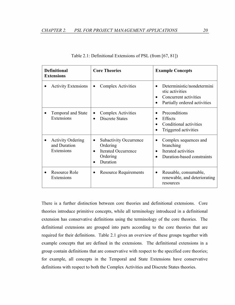
Table 2.1: Definitional Extensions of PSL (from [67, 81])
Definitional Extensions
Core Theories Example Concepts
• Activity Extensions • Complex Activities • Deterministic/nondeterministic activities
• Concurrent activities • Partially ordered activities
• Temporal and State Extensions
• Complex Activities • Discrete States
• Preconditions • Effects • Conditional activities • Triggered activities
• Activity Ordering and Duration Extensions
• Subactivity Occurrence Ordering
• Iterated Occurrence Ordering
• Duration
• Complex sequences and branching
• Iterated activities • Duration-based constraints
• Resource Role Extensions
• Resource Requirements • Reusable, consumable, renewable, and deteriorating resources
There is a further distinction between core theories and definitional extensions. Core
theories introduce primitive concepts, while all terminology introduced in a definitional
extension has conservative definitions using the terminology of the core theories. The
definitional extensions are grouped into parts according to the core theories that are
required for their definitions. Table 2.1 gives an overview of these groups together with
example concepts that are defined in the extensions. The definitional extensions in a
group contain definitions that are conservative with respect to the specified core theories;
for example, all concepts in the Temporal and State Extensions have conservative
definitions with respect to both the Complex Activities and Discrete States theories.

CHAPTER 2. PSL FOR PROJECT MANAGEMENT APPLICATIONS 21
2.2 Using PSL to Exchange Information among Project Management Applications
To exchange information using PSL, wrappers for individual applications need to be
implemented, so that they are PSL compliant. Section 2.2.1 first discusses semantic
mapping between PSL and project management application concepts, an important step
in wrapping applications. Section 2.2.2 then elaborates on how to develop wrappers for
different project management tools.
2.2.1 Semantic Mapping between PSL and Project
Management Application Concepts
PSL was designed to exchange process information among manufacturing applications.
In a pilot implementation at NIST, PSL was successfully used to exchange manufacturing
process information between the IDEF3-based ProCAP and the C++ based ILOG
Scheduler [80]. Although PSL was initially created mainly for the manufacturing
industry, the core theories can be extended to construction project management and
scheduling applications.
In our research, we first selected a typical project management tool, the Primavera
Project Planner (P3), as the benchmark application to help define the core concepts for
construction project management. Primavera P3 is a software tool for organizing,
planning, and managing activities, projects, and resources. The following discussion
focuses on the semantic mapping between Primavera P3 and PSL.
To achieve interoperability using PSL, semantic mapping is needed for various reasons.
First, the same term may have different meanings in different applications and universes
of discourse. For example, the term successor in PSL means that there are no other

CHAPTER 2. PSL FOR PROJECT MANAGEMENT APPLICATIONS 22
activities occurring between the two activities; however, in P3 the term does not have
such an implication and only indicates that one activity cannot start before the other.
Second, the same concept in different applications may be represented differently using
different terms. For instance, the terms Successor and Predecessor in P3 are used to
describe the dependency relationships; however, other terms, such as after-start and
after-start-delay, are used in PSL to describe the same concepts. To exchange project
scheduling information, we first need to map the concepts in different applications onto
the formal PSL ontology.
A typical construction project consists of a set of activities and the dependency
relationships among the activities. Construction activities can generally be categorized
into one of three types: production, procurement, and administrative activities. Each
activity has associated attributes, such as start date, duration, etc. Dependency
relationships describe the constraints defining the order in which the activities must occur
to complete the project [44]. There are four typical dependency relationships: Finish to
Start, Finish to Finish, Start to Start, Start to Finish. Figure 2.2 depicts the dependency
relationships and their respective definitions. For example, the “Finish to Start”
relationship between activity A and activity B means that B starts only after A completes,
and the “Finish to Finish” relationship indicates that A needs to complete before B does.
Each activity in a project schedule can be mapped onto an activity occurrence in PSL,
while the timepoint is used to specify the beginning and the end points of an activity
occurrence. PSL extensions provide terms to describe the dependency relationships
among activities. For example, the term before-start in PSL corresponds to the “Start to
Start” relationship, while the lag in the “Start to Start” relationship corresponds to the
PSL term before-start-delay. The PSL expression (before-start occ1 occ2 a3) specifies
that both occ1 and occ2 are subactivity occurrences of the activity a3, while the
beginning timepoint of occ1 is earlier than the beginning timepoint of occ2. In addition,
the expression (before-start-delay occ1 occ2 a3 d) implies that occ2 begins at least d

CHAPTER 2. PSL FOR PROJECT MANAGEMENT APPLICATIONS 23
timepoints after occ1 begins. Table 2.2 lists the terms that are used in Primavera P3 and
PSL to describe activities and dependency relationships.
In addition to activity and relationship information, resource allocation also plays an
important role in project scheduling. A project schedule is not completely specified
unless the necessary resources are allocated. Resources include people, material, and
equipment required to finish the work. Resources can be mapped onto the lexicon
resource in PSL, which identifies the object required by an activity.
A B
(a) Finish to Start
A B
(b) Finish to Finish
A B
(c) Start to Start
A B
(d) Start to Finish
Figure 2.2: Dependency Relationships among Activities

CHAPTER 2. PSL FOR PROJECT MANAGEMENT APPLICATIONS 24
Table 2.2: Mapping of Activities and Dependency Relationships
Concepts in Primavera P3
PSL terms
Activity Activity occurrence
Predecessor, Successor Activity occurrence, before-start, before-finish, after-start, after-finish
Start to Start before-start
Start to Finish before-finish
Finish to Start after-start
Finish to Finish after-finish
Dependency Lag before-start-delay, before-finish-delay, after-start-delay, after-finish-delay
Semantic mapping between PSL and project management applications is not always
straightforward. For example, the total float concept in Primavera P3 cannot be directly
mapped to a corresponding PSL term. In Primavera P3, total float indicates the
maximum amount of time a task can be delayed without postponing the whole project.
To express the total float concept, we need a set of PSL expressions. For example,
assuming that in Primavera P3 there is a project (proj1) with the scheduled completion
date on March 10, 2003, the activity A is scheduled to finish on October 7, 2002 with a
total float of 3 days. To express the total float concept in the above example, we need to
use the following PSL expressions.
(=> (beforeEQ (endof A) 10/10/2002) (beforeEQ (endof proj1) 03/10/2003) )
(=> (before 10/10/2002 (endof A)) (before 03/10/2003 (endof proj1) ) )

CHAPTER 2. PSL FOR PROJECT MANAGEMENT APPLICATIONS 25
Here October 10, 2002 is the completion date of the activity A if it is delayed by exactly 3
days. The first PSL expression implies that if A is delayed by no more than 3 days, the
project will be completed on time with the end date of the project remains to be March
10, 2003. The second PSL expression indicates that if the end date of activity A is
beyond October 10, 2002, the project completion date will then be postponed beyond
March 10, 2003.
Generally speaking, PSL has more expressive power than many project management
tools. In particular, PSL has the capability to express uncertainty, conditioning, and
universal and existential relations. As an example, the following PSL expressions can be
used to indicate that a construction activity may require different resources depending on
the result of other activities.
(activity-occurrence pourConcrete)
(doc pourConcrete “Pouring Concrete”)
(=> (beforeEQ (endof formColumns) 11/20/2002) (demand constructionWorker
pourConcrete 3) )
(=> (before 11/20/2002 (endof formColumns) ) (demand constructionWorker
pourConcrete 6) )
(after-start pourConcrete formColumns proj1)
Here, the activity pourConcrete requires different resources depending on its predecessor
formColumns. If the activity formColumns is not completed before November 20, 2002,
then the activity pourConcrete would require more construction workers. This
conditioning expression, however, cannot be represented or encoded using project
management tools that primarily handle deterministic scheduling.
Let’s look at a mapping example between Primavera P3 and PSL. Figure 2.3 shows the
major activities involved in the schedule of a typical residential building project. The

CHAPTER 2. PSL FOR PROJECT MANAGEMENT APPLICATIONS 26
project schedule is shown as a PERT (Primavera's Easy Relationship Tracing) chart from
the Primavera Project Planner. In the project, the activity “Frame House” needs to finish
before either the activity “Frame Roof” or “Install HVAC” can start. After the
completion of these two activities, the activity “Install Drywall” can proceed. Figure 2.4
shows the ASCII outputs of the scheduling and resource information of the project plan
from Primavera P3. For example, as shown in Figure 2.4, the activity “Frame House”
starts on August 5, 2002 and lasts 15 days, while the activity “Install Drywall” needs the
resource “drywall” to proceed.
The scheduling information in Primavera P3 can be described precisely using PSL.
Figure 2.5 shows portion of the PSL expressions for the example project. Here,
ResProject is the project identifier of the example residential building project. The PSL
expressions (after-start ID100 ID110 ResProject) and (after-start-delay ID100 ID110
ResProject 0) specify that the activity ID110 (“Frame Roof”) needs to start after the
completion of the activity ID100 (“Frame House”) with no lag between the two activities.
The PSL expression (available drywall ID130) indicates that the resource drywall is
available for the activity ID130 (“Install DryWall”), while the PSL expression (demand
drywall ID130 2220) specifies that the activity ID130 requires 2200 square feet of
drywall.
Figure 2.3: Example Dependency of a Scheduling Chart in Primavera P3

CHAPTER 2. PSL FOR PROJECT MANAGEMENT APPLICATIONS 27
ACT TITLE ES EF TF RD---------- --------------- -------- -------- ----- ----ID100 Frame House 5AUG02 23AUG02 0 15ID130 Install Drywall 5SEP02 2OCT02 0 20……
ACT RES RUT QTC QAC---------- -------- ---- ------------- ------------
ID130 DRYWALL sqft 2200.00 2200.00……
Figure 2.4: Schedule and Resource Information from Primavera P3
(and(activity-occurrence ID100)(doc ID100 "Frame House")(beginof ID100 08/05/2002)(duration-of ID100 15)(after-start ID100 ID110 ResProject)(after-start-delay ID100 ID110 ResProject 0)......
)(and
(resource drywall)(available drywall ID130)(demand drywall ID130 2220)
)......
Figure 2.5: PSL Expressions for the Example Chart in Primavera P3
2.2.2 Wrapping Project Management Applications
There are many commercial software tools as well as in-house computer programs that
have been developed for project management. These tools use different internal
representations and usually do not communicate to each other. To achieve
interoperability, different approaches have been proposed over the past decades. Among
them are direct translation, neutral file-based integration, centralized database, and
software interface. The pros and cons of these approaches are summarized in Table 2.3.

CHAPTER 2. PSL FOR PROJECT MANAGEMENT APPLICATIONS 28
Table 2.3: Pros and Cons of Different Data Integration Approaches
Methods Pros Cons
Direct Translation
• Only one translator is needed to achieve integration if there are only two programs.
• It requires the cooperation of two software developers to achieve interoperability.
• As the number of applications increase, the translators needed increase dramatically.
Neutral File Based Translation
• Only one translator is needed for each application.
• Software developers focus on the translator of their own tools.
• It requires more work if there are only two tools involved.
Centralized Database
• This approach has the potential to ensure that all participants have the latest information.
• It could be difficult to define a common schema.
• It requires extra programming effort to interact with database.
Software Interface
• This approach has more flexibility in automating the translating process.
• Programmers need to understand APIs of individual tools.
• It may require significantly more programming effort.
• It may not work when no API is provided.
To achieve interoperability among computer tools using PSL, it is necessary to develop
wrappers for each individual tool. The specific implementation might be different
depending on individual tools. There are two major considerations in selecting an
appropriate approach to wrapping a legacy application:

CHAPTER 2. PSL FOR PROJECT MANAGEMENT APPLICATIONS 29
• The Input/Output methods the legacy application supports.
Typical Input/Output (I/O) methods includes application programming interface
(API), neutral files, proprietary files, databases, and interactive interfaces.
Different legacy applications may support some or all of the methods. The
wrapping approach is thus limited to the I/O methods that the legacy tool
supports. For example, we cannot use the API approach to interact directly with a
legacy tool if the tool does not provide programming interface.
• Developer’ requirement
When more than one Input/Output method is provided by a legacy tool, it is up to
the software developers to choose a method based on their specific requirements.
For example, file-based approaches require less programming effort than the API-
based approach; however, they also provide less flexibility in automation. In this
research, the goal is to automate the data integration process as much as possible;
thus, the programming interface approach is employed whenever possible.
To exchange project scheduling information among different project management
applications, we need to develop wrappers for each application. The PSL wrappers are
used to retrieve and transfer information between the applications, to map between
application concepts and PSL ontology, and to parse and generate PSL files. Figure 2.6
shows a variety of software applications that have been wrapped using PSL. Currently,
these applications include the Primavera Project Planner (P3), Microsoft Project, Vite
SimVision, 4D Viewer, AutoCAD Architectural Desktop, the GeneralCost Estimator, and
Microsoft Excel. As depicted in Figure 2.6, wrappers for individual applications need
different implementations. The implementations of a few wrappers are listed as follows:
• For Vite SimVision, we use Java Database Connectivity (JDBC) to parse the
relevant information stored in the Access database created by the tool, translate
the information into PSL, and create a PSL file. For the PSL to Vite SimVision

CHAPTER 2. PSL FOR PROJECT MANAGEMENT APPLICATIONS 30
translation, the information in the PSL file is parsed and rewritten into VNB
(Access database) file format.
• For Primavera P3, the Primavera Automation Engine (RA) is employed. The RA
is a set of object-oriented, OLE 2.0-based API, which allows object-oriented
programming access to the P3 scheduling engine and other applications. We use
RA to communicate with P3, such as retrieving project scheduling information
from P3 and transferring this information to P3.
• For Microsoft Project, VBA (Visual Basic for Application) as well as the
Microsoft Project Object Model is employed. The process here is very similar to
the communication protocols for Primavera P3.
• For 4D Viewer (McKinney and Fischer 1998), the scheduling information from
the PSL file is retrieved and converted into ASCII format required by the 4D
Viewer.
• For Microsoft Excel, VBA is employed as the programming language. In
addition, the Microsoft Excel Object Model is utilized to retrieve and update
project information.
• For AutoCAD Architectural Desktop (ADT), we use VBA as well as the
AutoCAD ActiveX Object Model.
• The GeneralCost Estimator is a cost estimating tool running in Microsoft Excel.
The wrapping process for the tool is similar to the process for Microsoft Excel,
except that the data structures and functionalities provided by the estimator are
also utilized.

CHAPTER 2. PSL FOR PROJECT MANAGEMENT APPLICATIONS 31
PSL Files
Convert to PSL format PSL parser
Map PSL ontology to concepts inindividual software
Retrieve information fromapplications
P3: Primavera AutomationEngineMS Project, MS Excel, GC
Estimator: VBA + applicationmodulesVite SimVision: JDBC
Map concepts into formal PSLontology
Feed information into applications
P3: Primavera Automation EngineMS Project, MS Excel, GC
Estimator, AutoCAD: VBA +application modulesVite SimVision: JDBC4D Viewer: Plain text
PrimaveraP3
MSProject
ViteSimVision 4D Viewer
MS Excel GeneralCostEstimator
AutoCADADT
ProjectManagementApplications
Wrappers
Retriving andUpdating
Information
OntologyMapping
SyntacticTranslatiom
Figure 2.6: PSL Wrappers
As shown in Figure 2.7, the wrapping process is decomposed into three modules: I/O
modules, mapping modules, and translation modules. By decomposing a wrapper into
three modules, we standardize the wrapping process and improve the reusability of
previous modules.
• A syntactic translation module include a PSL parser and generator, which are
responsible for parsing and generating PSL files according to the PSL syntax,
respectively. This module can be reused by wrappers for other project
management tools with no or minimal changes.

CHAPTER 2. PSL FOR PROJECT MANAGEMENT APPLICATIONS 32
• Semantic mapping depends not only on the PSL ontology but also on the concepts
used in the individual applications. For many applications in the same domain,
the concepts are similar. Thus, the semantic mapping module can also be reused
by future PSL wrappers with appropriate changes in the terminology of
application concepts.
• Input/Output (I/O) modules are responsible for retrieving and updating
information in project management tools. The implementation of an I/O module
depends on the I/O methods supported by the tool and its internal data
representations. Thus, I/O modules cannot be reused if project management tools
do not support the same Input/Output methods. However, these modules can also
be partly reused among a number of project management tools. For example,
Microsoft Project, Microsoft Excel, AutoCAD ADT, and the GeneralCost
Estimator all support VBA programming. The only difference is their individual
Object Modules. Thus, a significant part of the I/O modules can also be reused
among the wrappers for these applications.
As noted, modularizing the wrappers encourages shareability and reusability of the codes
for different application tools. In summary, the syntactic translation modules have the
greatest reusability, because they deal with PSL files in standard ontology. On the other
hand, the I/O modules have to interact with different project management tools; thus,
they are less likely to be reusable.

CHAPTER 2. PSL FOR PROJECT MANAGEMENT APPLICATIONS 33
Project Management Tools� Different Internal Data Representations� Different Input/Output Methods
PSL Files(Standard
PSL Ontology)
I/O Module(Retrieving and Updating Information)
Mapping Module(Senmantic Mapping)
Translation Module(Syntactic
Translation)
Figure 2.7: The Decomposition of PSL Wrappers
A PSL parser, as part of the wrappers, has been developed to read the project scheduling
information from PSL files. One simplification we made in the PSL parser is that PSL
sentences are expressed as relations rather than functions. In PSL, each function has a
unique value; for example, in the PSL expression (endof A), the activity A can only have
one unique completion date. In contrast, the value of a relation is either true or false;
furthermore, relations can have disagreement on the last element. For example, the
relations (before t1 t2) and (before t1 t3) differ. As a result, every function can be
expressed as an equivalent relation with axioms that ensure the uniqueness of values,
while not every relation can be expressed as a function. Therefore, using relations is

CHAPTER 2. PSL FOR PROJECT MANAGEMENT APPLICATIONS 34
usually more convenient than using functions and minimizes unnecessary confusions and
complexities in implementing the PSL parser.
It should be noted that only the information that is common to the applications can be
exchanged. As shown in Figure 2.8, the Primavera Project Planner (P3) includes
scheduling, resource, and cost information, while Vite SimVision provides scheduling,
resource, communication, and organizational information. Scheduling and resource
information, which is common to both applications, can be exchanged through PSL.
However, not all scheduling and resource information is exchanged between these two
applications, since the granularity of such information may be different. For example,
Primavera P3 includes more detailed scheduling information than Vite SimVision; in
other words, not all scheduling information in Primavera P3 is needed by and transferred
to Vite SimVision.
Scheduling
Resource
Cost......
Scheduling
Resource
Communication
Organiztion......
Primavera P3 PSL Vite SimVision
Figure 2.8: Exchange Information between Primavera P3 and Vite SimVision through PSL

CHAPTER 2. PSL FOR PROJECT MANAGEMENT APPLICATIONS 35
2.3 Distributed Data Integration Infrastructure
Various architectures have been proposed to achieve software integration, such as
localized integration, client-server integration and distributed integration. Localized
integration involves integrating various software tools on one machine (e.g., a desktop
PC). In a client-server environment, software integration is often accomplished using a
project repository, which is either a neutral file or a database, residing on a central server,
to which all applications communicate to exchange information. In a distributed
environment, applications reside on different computers and are accessed over private or
public, local or wide area network.
In a construction project, it is not unusual that project management tools are
geographically distributed. The goal of a distributed integration infrastructure is to link
application tools and to act collaboratively on a project. We have prototyped a
distributed integration infrastructure using PSL as the information interchange standard
among different project management tools [26]. As shown in Figure 2.9, a
communication server is used to serve as the backbone of the system. The
communication server is responsible for listening requests from the communication
agents associated with different project management applications. When the server
receives a request, it broadcasts the request to different communication agents. For
example, the server may ask a communication agent to invoke a scheduling service or ask
the agent to transfer the scheduling result to another simulation tool. The communication
agents then pick up the request and process it. In addition, the Oracle database is used to
store the project information, so that users can access and update project information
through a Web browser.

CHAPTER 2. PSL FOR PROJECT MANAGEMENT APPLICATIONS 36
PrimaveraP3
MicrosoftProject
Oracle 8iRelationalDatabase
MicrosoftExcel
ViteSimVision
CommunicationServer
4D viewer
PSL Wrapper
Communication Agent
PSL Wrapper
Communication Agent
......
......
AutoCADADT
GeneralCostEstimator
ProjectManagement
ToolsDistributedat DifferentLocations
WebBrowser
Figure 2.9: A Distributed Integration Infrastructure
2.3.1 Translation between PSL and Database
The Oracle database is used to store project information so that it is accessible by users
through a Web browser. To use the database for data exchange, a database schema needs
to be defined. Table 2.4 illustrates the database schema in the current implementation.
The PROJECT table stores the overall information of projects. The ACTIVITY,
SCHEDULE, and DEPENDENCY tables are used to describe activities and their
relationships in the projects. The ACTOR table describes project participants, while the
ASSIGNMENT table stores the assignment information of project activities. All cost
information is stored in the COST table.

CHAPTER 2. PSL FOR PROJECT MANAGEMENT APPLICATIONS 37
Table 2.4: A Database Schema for the Project Repository
Tables Attributes
project projectid, description, companyname, workday, workhour, startdate, finishdate, costid
activity projectid, activityid, description, costid, scheduleid
actor projectid, actorid, description, role, hourwage
cost projectid, costid, actualcost, budgetedcost
schedule projectid, scheduleid, startdate, finishdate, actualstart, actualfinish, earlystart, earlyfinish, latestart, latefinish, duration, actualduration, freefloat, totalfloat
dependency projectid, dependencyid, activityid1, activityid2, relationship, driving, lag
assignment projectid, assignmentid, activityid, actorid
Once the schema is defined, a Java program is developed and employed to translate the
information between PSL and database. Figure 2.10 illustrates the translation process.
JDBC is used to establish connection to the database, and SQL statements are used to
query project information in the database. The information is then written into PSL
according to the syntax. In the reverse process, we can reuse the PSL parser that has
already been developed to parse project information. SQL operations are constructed
based on the information. The program finally connects to the database and writes the
information into the database.

CHAPTER 2. PSL FOR PROJECT MANAGEMENT APPLICATIONS 38
Oracle 8iRelationalDatabase
PSL ParserConstruct SQLSentences
Wrtie toDatabase
Write Results toPSL
Use SQL toQuery Databse
Connect toDatabse
PSLFiles
Figure 2.10: Translation between Database and PSL
2.3.2 Network Communication in the Distributed
Integration Framework
The network communication mechanism in the distributed integration framework is
illustrated in Figure 2.11. Java socket communication is used as the protocol between the
communication server and agents. A communication agent consists of an event listener,
an event dispatcher, and a data mapper. The messages in the system include control
messages and data messages. Control messages, such as invocation and termination
requests, are typically small in size. Data messages, such as the project scheduling
information and organization information, however, are usually bigger in size. The event
listener receives control messages, while the event dispatcher sends out control messages.
The data mapper is responsible for sending and receiving data messages.
Figure 2.12 shows a Java code segment of an event listener. The listener first defines two
data streams: one input stream and one output stream. It then creates a Socket on a
specific port. Finally, it keeps listening on the port to see if there are messages from the
server.

CHAPTER 2. PSL FOR PROJECT MANAGEMENT APPLICATIONS 39
Data Flow
Control Flow
Communication Server
EventListener
DataMapper
EventDispatcher
EventListener
EventDispatcher
DataMapper
Communication Agent
Java SocketCommunication
Figure 2.11: A Network Communication Framework
Public class ClientListener{
protected DataInputStream i; protected DataOutputStream o;public static void main (String args[]) throws IOException {
Socket s = new Socket (args[0], Integer.parseInt (args[1]));ClientListener client = new ClientListener(" " + args[0] + ":" +
args[1], s.getInputStream (), s.getOutputStream ());client.waitForEvent();s.close(); }
public void waitForEvent () {try { String line = i.readUTF ();}……}
......}
Figure 2.12: The Code Segment of an Event Listener
2.4 Demonstrations of Distributed Data Integration
In this section, two examples are used to demonstrate the integration of distributed
project management tools. We have conducted a number of demonstrations between

CHAPTER 2. PSL FOR PROJECT MANAGEMENT APPLICATIONS 40
Glasgow Caledonian University in Scotland and Stanford University [27]*. In the
demonstrations, the Oracle database server, the 4D Viewer, and the Vite SimVison are
located at Stanford University, while the scheduling services (e.g., Microsoft Project and
the Primavera Project Planner) reside at Glasgow Caledonian University.
2.4.1 Example 1: A Chip Design Scenario
We select a sample project from the tutorial of Vite SimVision software to test PSL for
the exchange of project scheduling information. A Vite SimVision project is composed
of a traditional CPM diagram and additional links showing failure dependence, reciprocal
information, and management structure. The example scenario, as shown in Figure 2.13,
is to design and fabricate a chip set for a new personal digital assistant (PDA) product.
There are 12 activities in this project. Among the 12 activities there are three milestone
activities: (1) Start Project, (2) Ship Tapes to Foundry, and (3) Fab, Test and Deliver. The
activity “Design_Coordination” maintains the overall control of the project.
Using PSL, we successfully exchange scheduling information among Vite SimVision, the
Primavera Project Planner (P3), and Microsoft Project. Figure 2.14 shows some selected
logic sentences from the PSL file particular to this project. These logic sentences specify
the properties of the project and activities in the project. For example, the expression
(beginof TUTO 9/18/1998) specifies that the TUTO project starts on 9/18/1998. The
expression (after-start ID190 ID200 TUTO) specifies that the task ID190 should finish
before the task ID200 starts.
* The demonstrations were conducted in collaboration with Professor Bimal Kumar of Glasgow
Caledonian University, UK.

CHAPTER 2. PSL FOR PROJECT MANAGEMENT APPLICATIONS 41
StartProject
Fab, Testand Deliver
DevelopSpecification
Write-Verify-Synth_B1RTL FullChipSynth
Sim_Gates
Eng Layout &Physical Ver'n
Assemble &verify_RTL
PartitionChip& Floor
PlanningGenerate Test
VectorsShip Tapesto Foundry
Design_Coordination
Figure 2.13: Original CPM Diagram in Vite SimVision
(and(project TUTO)(doc TUTO "TUTORIAL Project")(beginof TUTO 9/18/1998)(subactivity-occurrence ID100 TUTO)
……)(and
(activity-occurrence ID190)(doc ID190 "PartitionChip & Floor Planning")(beginof ID190 10/19/1998)(duration-of ID190 42)(after-start ID190 ID200 TUTO)(after-start-delay ID190 ID200 TUTO 0)
……)
Figure 2.14: Sample PSL File
Figures 2.15 to 2.17 illustrate the generated schedule in Vite SimVision, P3, and
Microsoft Project. Figure 2.15 is the original Gantt chart of the sample project in Vite
SimVision. Figures 2.16 and 2.17 show the regenerated project schedule in P3 and
Microsoft Project, respectively. As shown in the figures, project scheduling information
is successfully exchanged among these three applications. Activities have the same start
date and duration in all three applications. The critical paths are also the same in all three
applications.

CHAPTER 2. PSL FOR PROJECT MANAGEMENT APPLICATIONS 42
Figure 2.15: Original Gantt Chart in Vite SimVision
Figure 2.16: Regenerated Schedule in Primavera P3 using PSL
Figure 2.17: Regenerated Schedule in Microsoft Project using PSL

CHAPTER 2. PSL FOR PROJECT MANAGEMENT APPLICATIONS 43
In this example scenario, the scheduling information from Vite SimVison is retrieved and
converted into a PSL file. The information in the PSL file is then parsed and used to
regenerate the project schedule in the Primavera Project Planner and Microsoft Project.
The successful information exchange among these applications shows the potential of
PSL as an interchange standard in construction project management.
2.4.2 Example 2: Mortenson Ceiling Project
We demonstrate the scalability and applicability of PSL as an interchange standard
through the Mortenson Ceiling Project, which is part of the Walt Disney Concert Hall,
built by Mortenson Construction and designed by Frank O. Gehry & Associates*. There
are 191 activities and 459 dependency relationships in this example project. PSL is
employed as the data standard to exchange project scheduling information among
Primavera P3, Microsoft Project, and 4D Viewer. The PSL file of this project contains
more than 2000 logic sentences.
Figures 2.18 to 2.20 show selected results of this example demonstration. Figure 2.18 is
the original Gantt chart of the ceiling project in the Primavera Project Planner (P3).
Figure 2.19 shows a snapshot of the construction progress in 4D Viewer on March 25,
2001. The scheduling information originally in P3 is successfully transferred to
Microsoft Project using PSL, as shown in Figure 2.20.
To further illustrate the information exchange process, we altered the duration of activity
18T1-33201 from 1 day to 40 days in Microsoft Project, as shown in Figure 2.21. The
regenerated information is exchanged and displayed using P3 in Figure 2.22 and 4D
Viewer in Figure 2.23. The successful information exchange on this project demonstrates
the scalability, applicability, and robustness of PSL as an interchange standard.
* The building model and the 4D viewer were provided by Professor Martin Fischer and his research
group at Stanford University.

CHAPTER 2. PSL FOR PROJECT MANAGEMENT APPLICATIONS 44
Figure 2.18: Original Schedule in Primavera P3
Figure 2.19: Model in 4D Viewer Taken on March 25, 2001
Figure 2.20: Regenerated Gantt Chart in Microsoft Project using PSL

CHAPTER 2. PSL FOR PROJECT MANAGEMENT APPLICATIONS 45
Figure 2.21: Updated Project Schedule in Microsoft Project
Figure 2.22: Updated Project Schedule in Primavera P3
Figure 2.23: Updated Model in 4D Viewer Taken on March 25, 2001
CHAPTER 2. PSL FOR PROJECT MANAGEMENT APPLICATIONS 46
2.5 PSL for Consistency Checking
2.5.1 Conflicts in Project Management
Conflicts are ubiquitous in everyday life. The Oxford English Dictionary defines conflict
as “the clashing or variance of opposed principles, statements, arguments, etc.” Brown
[17] defines conflict as “a form of interaction among parties that differ in interests,
perceptions, and preferences.”
Conflicts are commonplace on large construction projects, since each project by itself has
its unique character and thus is a new venture. No two building products are exactly the
same. To name a few, design specifications, site conditions, management teams, and
financial situations vary from project to project. Experiences gained from past projects
cannot be fully transferred to new ones. The information at hand is often conflicting,
inconsistent, and incomplete.
Project personnel spend a great deal of time handling various conflicts. It has been
estimated that as much as 80% of their time is spent dealing with conflicts [84].
Conflicts arise due to many factors and can occur from time to time during the course of
a construction project. The interaction of different intellects, beliefs, cultures,
personalities, and educational backgrounds may all generate conflicts. Design changes,
unexpected weather conditions, labor actions, and procurement delays are common bases
for conflicts during various project stages. One method to classify conflicts is by the
source of conflicts, as follows [85]:
• Conflict of interests, the discrepancy among involved parties on preferred
outcomes.
• Conflict of values, the discrepancy in beliefs or ideologies.

CHAPTER 2. PSL FOR PROJECT MANAGEMENT APPLICATIONS 47
• Conflict of opinions, the discrepancy in the best way to accomplish a shared goal.
• Conflict of information, the discrepancy in project information (e.g., scheduling,
resources, physical conditions).
This research focuses on conflicts of information in project management. In a distributed
engineering environment, such conflicts occur more often due to incremental changes and
miscommunications. For example, a subcontractor may change its sub-schedule without
realizing the potential impact on other project participants. Thus, conflicts occur among
the schedules of different participants.
2.5.2 Review of Existing Approaches in Conflict
Resolution
There are two major approaches to solving information inconsistency problems in project
management. One method is to employ a centralized database, where all project
information is stored. The other one is to use various heuristic approaches for specific
domain problems.
A centralized database enables all project participants to be in tune with the latest
information; thus, version conflicts can be eliminated with this approach. However, this
approach does not address any logic conflicts. For example, a centralized database can
ensure that all participants have the latest information, but it cannot ensure that there are
no internal conflicts in the information itself.
Heuristic approaches are employed to solve many specific conflicts in project
management. For example, Akinci et al. [2] developed a taxonomy to categorize and
detect time-space conflicts. The drawback is that it is difficult to generalize such
heuristic solutions to handle conflicts that are outside of the defined domain problem.

CHAPTER 2. PSL FOR PROJECT MANAGEMENT APPLICATIONS 48
2.5.3 Consistency Checking using PSL
PSL can be used to check the consistency of project information from different sources.
In particular, PSL can be used to detect logic conflicts in the project base, where
information comes from heterogeneous applications. For example, as illustrated later,
our initial investigation shows that it is possible to detect version conflicts and cyclic
dependency relationships between the Primavera Project Planner and Microsoft Project.
With the conflicts found, it will be relatively easy to trace back to the sources of the
conflicts. In addition, project personnel can check assumptions using PSL. For instance,
suppose one would like to find out whether an activity can start on a specific date, say on
November 15, 2001 without causing conflicts with other activities or prolonging the
project. With PSL, we can add one piece of knowledge, which in PSL format would be
(beginof activity 2001-11-15), into the PSL knowledge base, and reason on the whole
knowledge base. If no conflict is found during the reasoning, project personnel can infer
that the assumption is reasonable; in other words, in this example, the activity can start on
November 15, 2001.
Figure 2.24 depicts the basic process for detecting the conflicts or inconsistency of
project information in the prototype implementation. PSL wrappers are employed to
retrieve project information from different applications. In this work, we employ a
theorem-prover---Otter (Organized Techniques for Theorem-proving and Effective
Research)---as the logic reasoning tool [65, 102]. Otter infers conclusions from given
hypotheses and takes two types of input: logic clauses and first-order logic sentences.
Internally, Otter converts all inputs into logic clauses and applies inference rules to all
possible logic clauses to infer new facts or conclusions.

CHAPTER 2. PSL FOR PROJECT MANAGEMENT APPLICATIONS 49
PrimaveraP3
MicrosoftProject Vite
PSL Files
Otter Input
PSL Axioms
4D Viewer
Reasoning Results
......
......PSLWrapper
PSLWrapper
PSLWrapper
PSLWrapper
PSL to OtterTranslator
Otter(First Order Logic
Reasoning Tool)
Figure 2.24: Consistency Checking using PSL
To utilize Otter, a translator has been developed to convert PSL files and PSL axioms
into first-order logic sentences that Otter can understand. Both PSL and Otter inputs are
based on first-order logic, and they have only minor differences in syntax. For example,
in PSL a predicate and its variables are all within a pair of parentheses, while in Otter a
predicate is followed by a pair of parentheses containing its variables. Figure 2.25 shows
the translation from PSL files to Otter inputs.

CHAPTER 2. PSL FOR PROJECT MANAGEMENT APPLICATIONS 50
(activity-occurrence 00H0-8011D)(beginof 00H0-8011D 2001-01-31)(duration-of 00H0-8011D 90)(freefloat 00H0-8011D 0)(totalfloat 00H0-8011D 29)(after-start 00H0-8011D 00H0-8011SCEIL)(after-start-delay 00H0-8011D 00H0-8011S CEIL 0.0)
PSL Expressions
activity_occurrence(00H0_8011D).beginof(00H0_8011D, 11384).duration_of(00H0_8011D, 90).freefloat(00H0_8011D, 0).totalfloat(00H0_8011D, 29).after_start(00H0_8011D,00H0_8011S, CEIL).after_start_delay(00H0_8011D,00H0_8011S, CEIL, 0).
Otter Input
Figure 2.25: Converting PSL Expressions into Otter Input
Project knowledge base� PSL Core, PSL Outer Core, and PSL Extensions� Project Specific Knowledge
Knowledgeto be added
Knowledgeto be deleted
Infer newknowledge
RewriteKnowledge
Updateknowledge
base
Figure 2.26: Simplified Reasoning Process in Otter
The reasoning process using Otter is summarized in Figure 2.26. Otter first infers new
conclusions from the existing knowledge base. Otter then rewrites the new knowledge
and checks whether it is subsumed by the existing knowledge. If not, the new knowledge
will be added to the existing knowledge base; otherwise, it will be deleted. Usually, the
reasoning process will stop either when Otter finds conflicts or when no further
conclusions can be inferred.
The knowledge base includes two main parts: (1) axioms and definitions from PSL Core,
PSL outer core, and PSL Extensions; and (2) facts of individual projects from

CHAPTER 2. PSL FOR PROJECT MANAGEMENT APPLICATIONS 51
heterogeneous sources. The reasoning among the axioms and definitions can
significantly slow the reasoning process without producing essential results. We
therefore partition the inputs into two lists: the axioms on the usable list and the project-
specific facts on the SOS (set of support) list. The performance of Otter can be
significantly improved by separating the project specific knowledge and the PSL
axioms/definitions. For example, in the chip design project to be presented in the
demonstration section, Otter takes only seven seconds to complete the reasoning, as
compared to several hours without partitioning.
2.5.4 Demonstration of the Consistency Checking
Prototype
This section presents an example to demonstrate how PSL can be used for consistency
checking. A chip design scenario is used to test the potential of PSL for consistency
checking purpose. The example project includes the design and fabrication of a chip set
for a new personal digital assistant (PDA) product. It involves managing design tasks as
well as the foundry’s layout, testing, and manufacturing tasks. Here we assume that there
are two groups working on the project: one primarily responsible for the foundry’s
layout, and the other primarily responsible for testing and manufacturing tasks. We
assume that the two groups employ different application software and work on the
schedule independently but collaboratively. In addition, we assume that group 1 uses
Primavera P3 to create the detailed schedule. Moreover, in this group’s schedule the
“Eng Layout & Physical Ver’n” task is assumed to start after the “General Test Vector”
task. Figure 2.27 shows the group 1’s schedule in Primavera P3, and Figure 2.28 shows
the group’s CPM diagram.
For group 2, Microsoft Project is employed as the project management tool.
Furthermore, the task “PartitionChip & Floor Planning” is split into two tasks: task
“PartitionChip” and task “Floor Planning.” In addition, in the schedule, group 2 assumes

CHAPTER 2. PSL FOR PROJECT MANAGEMENT APPLICATIONS 52
that the task “Sim_Gates” should follow the task “Eng Layout & Physical Ver’n.” Figure
2.29 shows group 2’s schedule in Microsoft Project, and Figure 2.30 shows the CPM
diagram.
Figure 2.27: Group 1’s Schedule in Primavera P3
StartProject
Fab, Testand Deliver
DevelopSpecification
Write-Verify-Synth_B1RTL FullChipSynth
Sim_Gates
Eng Layout &Physical Ver'n
Assemble &verify_RTL
PartitionChip& Floor
Planning
Generate TestVectors
Ship Tapesto Foundry
Design_Coordination
Figure 2.28: Group 1’s CPM Diagram
Figure 2.29: Group 2’s Schedule in Microsoft Project
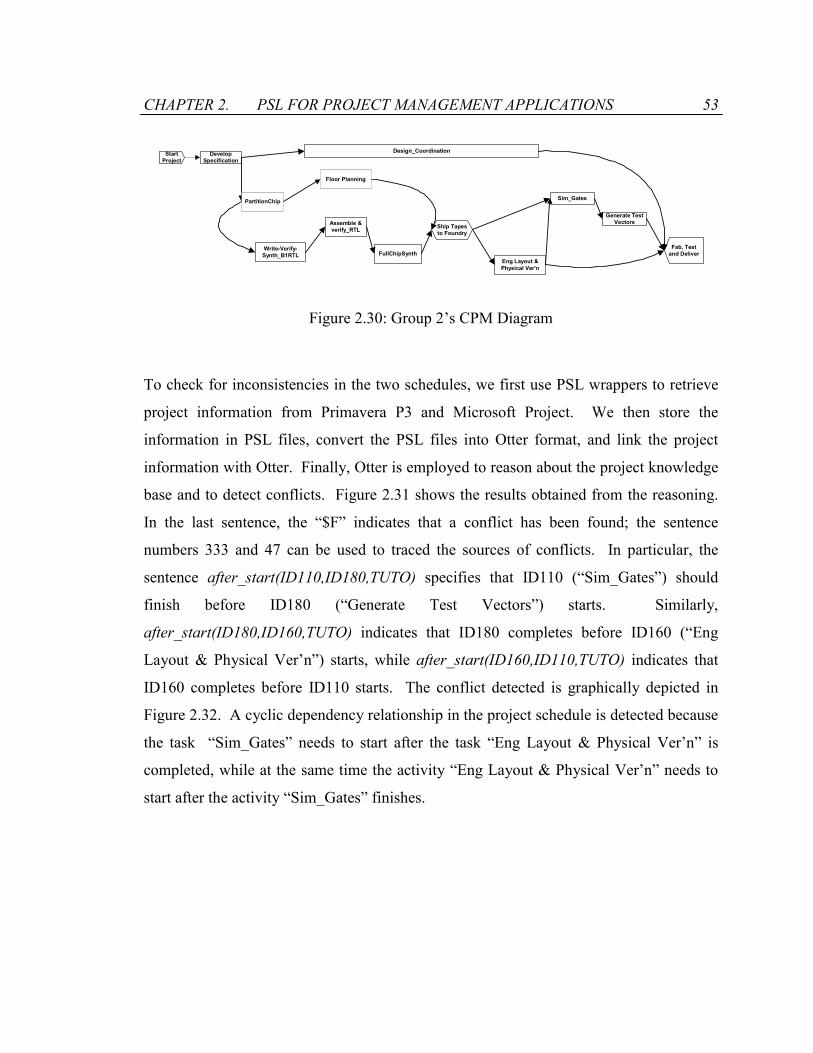
CHAPTER 2. PSL FOR PROJECT MANAGEMENT APPLICATIONS 53
StartProject
Fab, Testand Deliver
DevelopSpecification
Write-Verify-Synth_B1RTL FullChipSynth
Sim_Gates
Eng Layout &Physical Ver'n
Assemble &verify_RTL
Generate TestVectors
Ship Tapesto Foundry
Design_Coordination
Floor Planning
PartitionChip
Figure 2.30: Group 2’s CPM Diagram
To check for inconsistencies in the two schedules, we first use PSL wrappers to retrieve
project information from Primavera P3 and Microsoft Project. We then store the
information in PSL files, convert the PSL files into Otter format, and link the project
information with Otter. Finally, Otter is employed to reason about the project knowledge
base and to detect conflicts. Figure 2.31 shows the results obtained from the reasoning.
In the last sentence, the “$F” indicates that a conflict has been found; the sentence
numbers 333 and 47 can be used to traced the sources of conflicts. In particular, the
sentence after_start(ID110,ID180,TUTO) specifies that ID110 (“Sim_Gates”) should
finish before ID180 (“Generate Test Vectors”) starts. Similarly,
after_start(ID180,ID160,TUTO) indicates that ID180 completes before ID160 (“Eng
Layout & Physical Ver’n”) starts, while after_start(ID160,ID110,TUTO) indicates that
ID160 completes before ID110 starts. The conflict detected is graphically depicted in
Figure 2.32. A cyclic dependency relationship in the project schedule is detected because
the task “Sim_Gates” needs to start after the task “Eng Layout & Physical Ver’n” is
completed, while at the same time the activity “Eng Layout & Physical Ver’n” needs to
start after the activity “Sim_Gates” finishes.

CHAPTER 2. PSL FOR PROJECT MANAGEMENT APPLICATIONS 54
44 [] -after_start(x100,x101,x102)| -after_start(x101,x103,x102)|after_start(x100,x103,x102).47 [] -after_start(x111,x112,x113)| -after_start(x112,x111,x113).85 [] after_start(ID110,ID180,TUTO).136 [] after_start(ID180,ID160,TUTO).252 [] after_start(ID160,ID110,TUTO).310 [hyper,136,44,85] after_start(ID110,ID160,TUTO).333 [hyper,310,44,252] after_start(ID160,ID160,TUTO).361 [hyper,333,47,333] $F.
Figure 2.31: Reasoning Results in Cyclic Dependency Relationships
Sim_Gates GenerateTest Vectors
Eng Layout &Physical Ver'n
From Primavera P3
From MS Project
Figure 2.32: Cycle in Dependency Relationships
In addition to logic conflicts in the activity relationships, other conflicts (e.g., conflicts
arising due to versioning problems) can also be detected. For example, the same activity
may have different start dates or durations in Primavera P3 and Microsoft Project. To
find these conflicts, we can simply add the following axioms into the knowledge base.
(forall ?a ?t1 ?t2 (=> (beginof ?a ?t1) (beginof ?a ?t2) (= ?t1 ?t2))
(forall ?a ?d1 ?d2 (=> (duration-of ?a ?d1) (duration-of ?a ?d2) (= ?d1 ?d2))
The first axiom specifies that the start date of an activity is unique. In other words, if an
activity has two start dates, these two start dates must be equal. Similarly, the second
axiom specifies that the duration of an activity is unique. These axioms will guarantee
that an activity has a unique start date or duration. With these axioms added into the

CHAPTER 2. PSL FOR PROJECT MANAGEMENT APPLICATIONS 55
project knowledge base, Otter can detect those activities that have different start dates or
durations in Primavera P3 and Microsoft Project.
Figure 2.33 shows the sample conflict of the start dates of the activity ID210 (“Fab, Test
and Deliver”) detected by the reasoning tool. The first logic sentence in Figure 2.33
indicates that an activity must have a unique start date. Since Otter cannot directly
operate on dates, we assume 01/01/1970 as the base date and use the Java class Calendar
to convert the dates into numeric values. The second logic sentence
beginof(ID210,10738) specifies that the activity ID210 starts at 10738 that is equivalent
to 04/27/1999, as shown in Figure 2.27, which displays the project schedule using
Primavera P3. Similarly, in the logic sentence beginof(ID210,10773), the numeric value
10773 corresponds to the date 06/01/1999, which is the start date of the activity ID210
from the schedule shown in Figure 2.29 using Microsoft Project. The last logic sentence
in Figure 2.33 concludes that the activity ID210 has different start dates in the schedules
from Primavera P3 and Microsoft Project, thus causing inconsistency.
The above examples show that PSL can be used to detect inconsistencies in the project
knowledge base. Following the proof process, we can trace the root of the conflicts,
identify the causes, and help resolve the inconsistency problems in the project.
59 [] -beginof(x162,x163)| -beginof(x162,x164)|x163==x164.161 [] beginof(ID210,10738).273 [] beginof(ID210,10773).323 [hyper,273,59,161,demod,propositional] $F.
Figure 2.33: Reasoning Results in Version Conflicts

CHAPTER 2. PSL FOR PROJECT MANAGEMENT APPLICATIONS 56
2.5.5 Soundness and Completeness
The soundness and completeness of the consistency checking prototype largely depends
on the soundness and completeness of the employed logic reasoning tool. In this
research, it depends on the soundness and completeness of Otter.
• Soundness
The consistency checking prototype is sound if a conflict detected by the
prototype is indeed a conflict; in other words, the reasoning process is valid.
Otter has a very good record on soundness, but no part of it (approximately
28,000 lines of C code) has been formally verified [65]. Thus, any conflicts
detected by the prototype may need to be checked manually or by another
independent program.
• Completeness
The consistency checking prototype is complete if it detects all conflicts in the
knowledge base. Theoretically, the proof system of Otter is not complete [65]. In
Otter, many strategies have been adopted to save time and memory. These
strategies might be incomplete in theory; however, careful use of these strategies
does not prevent Otter from finding proofs in practice [65].
To test the soundness and completeness of the consistency checking prototype, four
example projects were employed, and various conflicts were created manually. The
prototype was then tested on these examples to see if the system is sound and complete.
In the demonstration, the following types of conflicts were manually created and mixed
into individual example projects:
• Inconsistent dates (e.g., start dates and finish dates)
• Inconsistent task durations

CHAPTER 2. PSL FOR PROJECT MANAGEMENT APPLICATIONS 57
• Cyclic dependency relationships (A cycle may involve two, three, or more
activities.)
• Conflicts of resource competition among activities (e.g., two activities compete
for one crane at the same time.)
Table 2.5 shows the test results of the prototype system on soundness and completeness.
In all test cases, the system successfully detected all the conflicts and did not infer any
false conflicts. These experiments illustrate that the theorem prover can be employed
reliably for conflict detection and consistency checking applications.
Table 2.5: Soundness and Completeness of the Consistency Checking Prototype
Test Soundness Completeness
Project 1 (1 conflict)
Project 2 (3 conflicts)
Project 3 (8 conflicts)
Project 4 (12 conflicts)

CHAPTER 2. PSL FOR PROJECT MANAGEMENT APPLICATIONS 58
2.5.6 Performance Analysis of Consistency Checking
Performance is a major issue for many logic reasoning systems. As the knowledge base
increases, the required reasoning time usually increases dramatically, which frequently
makes a logic reasoning system not useful for practical situations. We examine the
performance issue by testing the consistency checking prototype on four example
projects with different sizes. The smallest project consists of 12 activities and 101 pieces
of project specific facts, while the largest project has 460 activities and 5147 pieces of
project specific facts*. The experiments were conducted on two computers. One is a
Dell computer with 1 GB memory and a 2.4 GHZ Intel Pentium IV CPU, and the other is
a Dell server with 4 GB memory and four 2.0 GHZ Intel Xeon CPUs.
Section 2.5.3 has briefly discussed the importance of partitioning the input. Basically, the
input includes two parts: (1) axioms and definitions from the PSL language specification;
and (2) project specific facts. These two parts can be put either into a single list as the
input of the reasoning tool, or into two separate lists as the input. By partitioning the
input into two separate lists, the reasoning among the PSL axioms and definitions
themselves has been eliminated, thus significantly reducing the reasoning time. To
illustrate the importance of partitioning, the consistency checking prototype was also
tested on the two smaller projects on the Dell server without partitioning the input.
The reasoning times on these projects are shown in Table 2.6. In all test cases, a cyclic
dependency relationship involving three activities was created for each project. We
recorded the time required by the consistency checking system to find all potential
conflicts in each project, not the time to find the first conflict.
* In the experiments with partitioning, only axioms and definitions related with project scheduling are
selected from the PSL specification and loaded into the logic reasoning tool; thus, only around 120 pieces of knowledge from the PSL core or extensions are used with partitioning instead of thousands of facts.

CHAPTER 2. PSL FOR PROJECT MANAGEMENT APPLICATIONS 59
Table 2.6: Performance Results of the Consistency Checking Prototype
Running Time
Partitioning the knowledge base
Project Project Size
Dell PC Dell Server
No-partitioning (on Dell Server)
Project 1 12 Activities 101 Pieces of Facts
7 sec
7 sec > 100 hours
Project 2 58 Activities 541 Pieces of Facts
11min 23 sec > 100 hours
Project 3 191 Activities 2064 Pieces of Facts
12 min 30 sec ---
Project 4 460 Activities 5147 Pieces of Facts
14 min 1min 23 sec ---
The following observations have been made from the test results on the consistency
checking prototype:
• It is difficult to predict the time required to detect conflicts in the knowledge base.
However, in general, running time increases non-linearly as the number of facts
increases in the project.
• Partitioning the input can dramatically reduce the reasoning time of the
consistency checking prototype. Even for a simple project that can be completed
in a few seconds with partitioning, the reasoning process fails to complete after
more than 100 hours when the input is not partitioned.
• By partitioning the input into two lists, the execution time can be quite
reasonable. As shown in Table 2.6, a fast computer with adequate memory can
significantly reduce the time of consistency checking even for relatively large
projects.

CHAPTER 2. PSL FOR PROJECT MANAGEMENT APPLICATIONS 60
These experiments illustrate the importance of partitioning the knowledge base when
applying the theorem prover. Furthermore, the performance of the logic-based reasoning
tool is acceptable for practical use in moderate size projects.
2.6 PSL for Constraint Scheduling
Project scheduling is frequently subject to many constraints, such as the targeted
completion dates, budget limits, and physical conditions. To develop a good schedule,
project personnel need to understand different constraints involved in scheduling. A
classification can help resolve the constraint problems and develop appropriate schedules.
2.6.1 Scheduling Constraint Categorization and
Expression
Since the 1970s the Critical Path Method (CPM) has been widely used for project
scheduling in the construction industry. Shortly after the adoption of the CPM method,
researchers started to realize the need to classify scheduling constraints. For example,
Antill and Woodhead [6] classified constraints according to origins, such as physical,
hazard, safety, and equipment constraints. Echeverry et al. [33] classified constraints
according to physical component relationships, trade interaction, path interference, and
code regulations.
In this work, the constraints are grouped into three categories: single-task constraints,
local constraints between two consecutive tasks, and global constraints that involve tasks.
This classification is based on the way such that constraints can be easily expressed in
PSL.

CHAPTER 2. PSL FOR PROJECT MANAGEMENT APPLICATIONS 61
Single-task constraints are those involving only one task. For example, the duration of a
task should be limited to a number of days (e.g., 20 days). Another typical single-task
constraint is that a task may have exactly one responsible contractor (e.g., a general
contractor or a sub contractor). In addition, schedulers often need to ensure that there are
no isolated tasks in the schedule. In other words, except for the start and finish tasks,
each activity needs to be connected to at least one predecessor and one successor.
One essential step to expressing these constraints in PSL is the semantic mapping
between the constraints and the corresponding PSL terms. The following examples
illustrate the mapping.
• The duration of an activity should be limited to N days.
(for all ?a ((<= (duration-of a) N)))
• Except the start activity, each activity should have a predecessor.
(forall ?a (=> (<> a start)
(exist ?a1 (or (before-start ?a1 ?a)
(before-finish ?a1 ?a))) )
• Except the finish activity, each activity should have a successor.
(forall ?a (=> (<> a finish)
(exist ?a1 (or (after-start ?a ?a1)
(after-finish ?a ?a1))) )
• Each task should have exactly one individual who is directly responsible for it.
(forall ?a (exist ?c ( assign a c) ))
(forall ?a (=> (assign a c1) (assign a c2) (= c1 c2)))

CHAPTER 2. PSL FOR PROJECT MANAGEMENT APPLICATIONS 62
Local constraints involve two neighboring tasks (e.g., constraints determining the
dependency relationships), such as.
• Physical component relationships (support, connect, cover, enclose, protect, etc.)
• Trade interaction (serviced by, damaged by, workspace, resource, etc.)
• Path interference
• Code regulation (inspection, testing, safety, etc.)
Here resource is used as an example to illustrate local constraints. In the example,
activity a1 and activity a2 require 3 and 5 units of resources respectively. There are only
6 units of resources available; thus, activities a1 and a2 cannot be performed in parallel
(e.g., activity a2 may have to start after the completion of activity a1.). The constraints
can be expressed in PSL as follows:
(resource r)
(resource_point 6)
(demand r a1 3)
(demand r a2 5)
(after-start a1 a2)
Global constraints refer to constraints involving multiple tasks (more than two) and even
for the whole project, such as.
• Project costs and durations
• Space constraints of the construction site
• Critical resource constraints (e.g., cranes)

CHAPTER 2. PSL FOR PROJECT MANAGEMENT APPLICATIONS 63
• External constraints (e.g., regulatory permissions, utility access, and unexpected
site/weather conditions)
Again, we use an example to illustrate how to express global constraints in PSL.
Suppose that on any given date a sub-contractor may not work on more than one task,
this constraint can be expressed as follows:
(forall ?sub ?a1 ?a2 ?d
( (activity ?a1)
(activity ?a2)
(actor ?sub)
(assigned ?a1 ?sub)
(assigned ?a2 ?sub)
(isbetween ?d (beginof ?a1) (endof ?a1))
(isbetween ?d (beginof ?a2) (endof ?a2))
(= ?a1 ?a2) ) )
2.6.2 PSL for Constraint Scheduling
To ensure that a schedule meets multiple constraints can be difficult, especially for large,
complex schedules with thousands of tasks and constraints. For example, in the San
Francisco De Young Museum project, there are over 4,000 tasks and 40 subcontractors.
In this project, it took over nine months for the project engineer to develop a schedule
that met the various constraints*.
* This information was obtained from the interview with Mr. Jeff Budke of Swinerton Builders, a project
engineer in the San Francisco De Young Museum project.

CHAPTER 2. PSL FOR PROJECT MANAGEMENT APPLICATIONS 64
PSL can be used to check whether a schedule meets certain constraints due to its logic
structure. Obviously, a PSL wrapper needs to be developed to express scheduling
information in PSL, as discussed earlier [25]. In addition, constraints need to be encoded
in PSL. A logic-reasoning tool can then be employed to detect potential conflicts
between the schedule and the constraints. The following example illustrates the use of
PSL in checking whether a schedule meets constraints.
Start
InstallHVAC
InstallElectrical
Finish
Figure 2.34: An Example Schedule
(and (activity-occurrence ID100)(doc ID120 "Start")......)
(and (activity-occurrence ID120)(doc ID120 "InstallHVAC")(beginof ID120 08/05/2002)(duration-of ID120 18)(after-start ID120 ID160 proj)(after-start-delay ID120 ID160
proj 0)(demand tool ID120 80)......)
......)
(and (activity-occurrence ID140)(doc ID140
"InstallElectrical")(beginof ID140 08/05/2002)(duration-of ID140 15)(after-start ID140 ID160 proj)(after-start-delay ID140 ID160
proj 0)(demand tool ID130 40)......)
(and (activity-occurrence ID180)(doc ID120 "Finsih")
......
Figure 2.35: The Scheduling Information Expressed in PSL

CHAPTER 2. PSL FOR PROJECT MANAGEMENT APPLICATIONS 65
Let us assume that there are four tasks in a simplified schedule: one start task, one finish
task, and two tasks in between, as shown in Figure 2.34. Initially, task ID120
(“InstallHVAC”) and task ID140 (“InstallElectrical”) are scheduled to conduct in
parallel, and they require 80 and 40 units of tools, respectively.
The scheduling information can be expressed in PSL expressions, as shown in Figure
2.35. The schedule itself is valid, and there are no internal conflicts. However, if
scheduling constraints exist, further analysis is then needed. For example, assume that
there are only 100 units of tools available for use, which could be expressed in the
following PSL expressions:
(and (resource tool)
(available tool 100) )
Potential conflicts may then arise due to resource limitation. With the help of a logic
reasoning engine, we can check whether the schedule satisfies the resource constraints.
In this example, the available resources are not adequate to conduct tasks ID120 and
ID140 in parallel, and a conflict is detected. Here P5 refers to an axiom about the PSL
relation agg_demand; basically, the aggregate demand for the resource equals the sum of
resources required by each activity. P8 is an axiom dictating that the aggregate demand
for resources should not exceed the available quantity. The following shows the
reasoning process:
P1: (demand tool ID120 80) {Assertion} P2: (demand tool ID140 40) {Assertion} P3: (<> ID120 ID140) {Assertion} P4: (agg_demand ?r N) {Assertion} P5: (?r ?a1 ?a2 ?n1 ?n2 ?n (demand ?r ?a1 ?n1) (demand ?r ?a2 ?n2) (<> ?a1 ?a2) (agg_demand ?r ?n)

CHAPTER 2. PSL FOR PROJECT MANAGEMENT APPLICATIONS 66
(= ?n (+ ?n1 ?n2)) {Axiom} P6: (= N 120)) {P1, P2, P3, P4, P5} P7: (available tool 100) {Assertion} P8: (?r ?n1 ?n2 ( (agg_demand ?r ?n1) (available ?r ?n2) (<= ?n1 ?n2) )) {Axiom} P9: (<= N 100) {P4, P7, P8} P10: (<= 120 100) {P9, P6}
P11: False {P10}
Adjustments are needed if a schedule fails to meet all constraints. In this example, we
can either add more resources or conduct tasks ID120 and ID140 in a sequential order.
Each option will lead to a schedule satisfying the resource constraint. It should be noted
that while the reasoning system is able to check conformity, it does not automatically
produce suggestions on alternatives. Instead, project personnel have to develop
alternatives and adjust the schedule when resource constraints are detected by the
reasoning system.
2.7 Summary
Data integration has always been a challenge for the engineering and construction
industry, where volumes of information are frequently generated by different software
applications. Although the Process Specification Language (PSL) was designed with the
aim of exchanging process information among manufacturing applications, our research
shows that PSL can also be applied to the engineering and construction industry. The
mapping between PSL and application concepts is first discussed, followed by the
discussion of how to wrap different project management tools. While each application
needs a separate wrapper, the modularity of the wrappers allows shareability and
reusability of the modules among different project management tools. A distributed

CHAPTER 2. PSL FOR PROJECT MANAGEMENT APPLICATIONS 67
integration framework is proposed to integrate typical project management applications.
The framework has been successfully demonstrated with two example projects. The
distributed framework and the data exchange provide ubiquitous access to the project
data from different tools in geographically dispersed locations. PSL is employed for
information exchange among project management tools in the simulation access
framework to be discussed in the next chapter.
As an ontology standard based on first-order logic, PSL has applications beyond data
exchange. This chapter has illustrated the potential applications of PSL in two areas:
consistency checking and constraint scheduling. A formal mechanism is proposed to
detect conflicts of project information arising from different sources. An example
demonstration is provided to illustrate the potential of PSL in consistency checking. In
addition, a method is presented to ensure conformity of project schedules to scheduling
constraints using PSL.

Chapter 3
A Simulation Access Language (SimAL) and Framework
In Chapter 2 we have demonstrated the applicability of PSL for project information
exchange. In particular, a distributed data integration framework has been implemented
and collaboratively demonstrated between Glasgow Caledonian University and Stanford
University. However, to simulate scenarios accomplished by different project
management tools, mechanism beyond data integration needs to be provided.
This chapter first presents an overview of a simulation access framework, a framework
designed with the aim of improving the reusability and extending the applications of
various project management tools. The simulation access language (SimAL) and
framework are then discussed in detail. The design criteria of SimAL are discussed,
followed by the SimAL components and specifications. This chapter then describes how
to build a compiler for the SimAL language. The implementation efforts of the SimAL
framework are also discussed in this chapter. In particular, data integration between
different computer tools is achieved using PSL based on the work described in Chapter 2.
The functions and implementation details of each module of the SimAL framework are

CHAPTER 3. A SIMULATION ACCESS LANGUAGE AND FRAMEWORK
69
presented. Finally, an example is provided to demonstrate the usage of the SimAL
language and framework.
3.1 Overview of the Simulation Framework
This research aims to develop a general simulation framework and language for
integration and coordination of application tools. The SimAL framework consists of
multiple layers, as illustrated in Figure 3.1. To be integrated into the SimAL framework,
each project management tool needs a wrapper. The layers between user interface and
application-dependent wrappers (discussed earlier in Chapter 2) provide the following
additional functions: updating project information and querying results, invocation and
coordination of distributed applications, and simulation of project scenarios.

CHAPTER 3. A SIMULATION ACCESS LANGUAGE AND FRAMEWORK
70
Simulate andCompare scenarios
Model Update& Result Query
Source SpecificCode
SimulationTools
Wrapper
Invocation andCoordinationInfrastructure
SimulationStatements &
Results
SimALQuery/Update
FICAS(DistributedInvocation &
Coordination)
SimALScenario Process
UserInterface
Figure 3.1: Conceptual Model of the SimAL System
To allow users to build services rapidly from existing software components, the
simulation framework is designed to provide the following functionalities:
• To invoke computer tools across different platforms and locations.
• To facilitate information exchange and to coordinate information flow among the
tools.
• To update project models in different computer applications.

CHAPTER 3. A SIMULATION ACCESS LANGUAGE AND FRAMEWORK
71
• To query specific information generated by different computer tools.
• To specify and compare different scenarios.
The SimAL framework involves distributed invocation and integration of various project
management tools. These tools may reside at different locations and may adopt different
internal data representations. Thus, an ontology standard is needed for information
exchange; in addition, a distributed invocation and coordination engine needs to be
provided for reusing these tools. Data integration has been discussed in Chapter 2. The
SimAL framework uses FICAS, a Flow-based Infrastructure for Composing Autonomous
Services, to support the integration of distributed software applications. The basic
architecture of FICAS is first reviewed in Section 3.2. Detailed discussions on FICAS
can be found in [62]. Potential applications with illustrative examples will be discussed
in Chapter 4.
3.2 A Brief Review of FICAS
SimAL employs FICAS [62], a service composition infrastructure for building
megaservices, to invoke and coordinate distributed project management tools. FICAS
allows distributed software applications to hide heterogeneities in the network, platform,
and language. Using FICAS, users can compose new services from existing tools
without paying attention to the details of network locations and communications. As
shown in Figure 3.2, FICAS consists of a buildtime environment and a runtime
environment [62]. The buildtime environment specifies the composition of the
megaservice from existing autonomous services, and the runtime environment executes
the operations specified in the composition. Autonomous services refer to the software
components that have clearly defined functions with accessible interfaces. Most legacy
project management tools can be wrapped to become autonomous services.

CHAPTER 3. A SIMULATION ACCESS LANGUAGE AND FRAMEWORK
72
FICAS uses CLAS (Compositional Language for Autonomous Services) as the language
to allow application programmers to compose megaservices. A CLAS program is
essentially a sequential specification of the relationships among collaborating services
[62]. As shown in Figure 3.2, a CLAS program is translated by the buildtime component
into a control sequence, which, in turn, invokes corresponding information services.
FICAS Buildtime
AutonomousService
Directory
CommunicationNetwork
CLASProgram
FICASControls
Autonomous Service
Autonomous Service
Autonomous Service
SoftwareApplication
AutonomousService Wrapper
FICAS RuntimeFICAS Buildtime
MegaserviceController
Figure 3.2: FICAS Architecture (from [62])
p3_svc = SETUP("SIP3")p3 = p3_svc.INVOKE("reschedule", ceil)ceil = p3.EXTRACT()p3_svc.TERMINATE()
Figure 3.3: Sample Code in CLAS

CHAPTER 3. A SIMULATION ACCESS LANGUAGE AND FRAMEWORK
73
Currently, CLAS includes autonomous service statements and conditional statements
[62]. Autonomous service statements are provided to accomplish procedure calls. In the
CLAS language, a procedural call to an autonomous service is split into four statements:
SETUP, INVOKE, EXTRACT, and TERMINATE. The SETUP statement is used to
establish communication to an autonomous service, the INVOKE statement is used to
execute the autonomous service, the EXTRACT statement collects the results generated
by the autonomous service, and the TERMINATE statement ends the connection to the
autonomous service. Conditional statements, including IF-THEN-ELSE and WHILE
statements, are employed to enable conditional executions. In particular, the IF-THEN-
ELSE statement is used to make dynamic branching decisions, and the WHILE statement
provides looping operations. In summary, the CLAS language provides a protocol that
programmers can utilize existing service components and compose additional services.
Figure 3.3 shows a sample code in CLAS, which calls for the Primavera Project Planner
to reschedule the project “ceil.”
In addition to FICAS, many other solutions are available for distributed computing.
However, earlier attempts in distributed computing using Remote Procedure Call (RPC)
[10], Distributed Component Object Model (DCOM) [88], Common Object Request
Broker (CORBA) [75], Enterprise JavaBeans (EJB) [77], and Remote Method Invocation
(RMI) [74] have key limitations such as platform dependency, tight coupling, and limited
interoperability. For example, RPC is primarily designed for tightly bounded but
geographically distributed systems. In CORBA, messages are manipulated by
instantiating objects. In contrast, Simple Object Access Protocol (SOAP) [13] and
FICAS support platform independency, loose coupling, and more powerful
interoperability. SOAP, an XML-based messaging protocol for information exchange in
a decentralized, distributed environment, is essentially a flexible form of the traditional
RPC mechanism for gluing distributed, heterogeneous applications together.
FICAS employs a distributed data flow implementation and is designed to handle high
data volume [60, 62], which is typically found in engineering. As shown in Figure 3.4,

CHAPTER 3. A SIMULATION ACCESS LANGUAGE AND FRAMEWORK
74
FICAS outperforms SOAP when the data volume is high [62]. The larger the data
volume, the bigger is the difference between the execution time of FICAS and SOAP
[62]. Because of the performance efficiency and its simple programming interface,
SimAL uses FICAS to support distributed application services.
0
2000
4000
6000
8000
10000
12000
14000
16000
18000
0 100 200 400 800 1600 3200
Data Volume (KB)
Meg
aser
vice
Exe
cutio
n Ti
me
SOAP (SingleService) SOAP (MultiService) FICAS (MultiService)
Figure 3.4: Comparison Between FICAS and SOAP on Local Area Network (from [62])

CHAPTER 3. A SIMULATION ACCESS LANGUAGE AND FRAMEWORK
75
3.3 The SimAL Access Language (SimAL)
This section discusses the SimAL language. Specifically, Section 3.3.1 discusses the
design goal of the language, and Section 3.3.2 describes the major components of the
language.
3.3.1 The Design Goal of the SimAL Language
The purpose of SimAL is to provide a simple, easy-to-use language to simulate scenarios
for project management and decision support applications. In general, three key factors
are involved in decision making: alternatives, information, and preferences. Alternatives
imply that more than one option could be available. Information refers to the knowledge
available to users about different options. Preferences specify the specific aspects that
users want to optimize. These three factors work together in shaping decision making.
With these factors in mind, SimAL is designed to provide supports for: setting
preferences, gathering information, and comparing alternatives. In particular, the
following goals are considered in the design of the SimAL language:
• High-level Programming
The intended users of SimAL are the participants in a project, who may not have
extensive programming experience. Thus, SimAL should be a high level
language and not involve the details of specific computer applications. In other
words, the SimAL language should be as simple as possible but with the
capability to allow users to specify simulation scenarios.
• Imperative Programming

CHAPTER 3. A SIMULATION ACCESS LANGUAGE AND FRAMEWORK
76
To simulate scenarios in project management, users need to describe tasks and
processes. Therefore, the SimAL language should support standard imperative
constructs, such as sequencing and iteration.
• Location-Independent Invocation
Many construction projects are geographically distributed; so is the deployment of
project management applications serving them. Hence, SimAL users should not
need to know the location of an existing service in order to invoke it. They
should only need to provide the name or description of the service.
• Physical Data Independence
Various project management application tools may use different internal data
representations. SimAL users should not need to know the physical formats of
the data (XML files, databases, etc.); they should only need to know the
representation schema.
• Transactions
The SimAL language needs to allow programmers to execute a sequence of
actions in an isolated and atomic fashion.
• Probabilities
In most projects, uncertainties, such as procurement delays and design changes,
are inevitable. The SimAL language needs to support probabilities and
uncertainties to facilitate predictive measure and scenario testing.
• Comparison
When changes occur on a project, frequently many options are available to study
the impact of the changes. Users should be able to use SimAL to investigate and

CHAPTER 3. A SIMULATION ACCESS LANGUAGE AND FRAMEWORK
77
compare multiple alternatives for the project. It is essential that the SimAL
language allows users to compare different options based on specific criteria.
3.3.2 The Components of the SimAL Language
There have been many previous and current efforts in developing languages for data
management, simulation tools, and service composition. Example languages include SQL
[42], SimQL [100], CLAS [62], WSFL [58], BPEL4WS [3], and DAML-S [5]. SimAL
incorporates many features from these existing languages. In particular, the distributed
service invocation in SimAL is based on CLAS, while the update and query statements in
SimAL are similar to SQL.
During the development of the SimAL language, a series of interviews with project
managers on the issues in utilizing various computer tools and information sources have
been conducted. The interviewers are from different organizations, including
subcontractors, general contractors, and facility owner companies. In addition, real
information (tasks, data, models) on construction projects ranging from small residential
apartments to major, complex institutional buildings has been collected and studied to
identify the requirements of project management applications. The inputs from project
managers and studies on actual projects provided many insights in designing the SimAL
language.
Based on the related languages and practical needs, the SimAL language is designed to
include the following major components:
• Invocation Statements, to invoke distributed computer tools across different
platforms.
• Operation Statements, to update project information in different computer
applications and to query specific information generated by these tools.

CHAPTER 3. A SIMULATION ACCESS LANGUAGE AND FRAMEWORK
78
• Control Statements, to control the flow of the simulation.
• Decision Support Statements, to create and compare scenarios.
The following sections discuss in details these SimAL language components.
3.3.2.1 Invocation Statements
In the CLAS language, a procedure call to an autonomous service is divided into four
statements: SETUP, INVOKE, EXTRACT, and TERMINATE. In SimAL, we simplify
the invocation task by reducing four statements into two: SETUP and INVOKE.
• Service Setup
ServiceHandle = SETUP(“ServiceName”)
The SETUP statement is used to establish communication with a simulation
application through its service name. ServiceName is a unique description of the
service, and ServiceHandle identifies the service and is used for the subsequent
invocation of the service. For example, the statement p3_svc =
SETUP("ServiceP3") establishes connection to Primavera P3, and the handle
p3_srv is used to invoke Primavera P3. The network location of the tool (e.g.,
Primavera P3) is available in the service directory, as will be discussed in Section
3.6.1.
• Service Invocation
Variable = ServiceHandle.INVOKE(param1, param2, …)
The INVOKE statement invokes a simulation service through the handle returned
from the SETUP statement. The parameters are used to provide values (e.g.,
project name) needed by the service, while the returned variable is associated with
the results generated by the service. For example, the statement arho1 =

CHAPTER 3. A SIMULATION ACCESS LANGUAGE AND FRAMEWORK
79
p3_svc.INVOKE("reschedule", arho, %%) invokes the Primavera P3 service
identified by the handle p3_svc. The first parameter reschedule specifies the
operation (asking Primavera P3 to reschedule the project), the second parameter
arho provides the data input to Primavera P3, and the third parameter %%
specifies the project name which is transferred to the SimAL system at run-time.
Here, the variable arho1 identifies the rescheduled results from Primavera P3, and
thus the results can be used as the input by other software applications through
arho1.
In SimAL, result extraction and service termination, which are accomplished through
EXTRACT and TERMINATE statements in CLAS, are conducted automatically.
Results from an invoked service are automatically extracted and stored in the Variable
associated with the invocation. The SimAL system scans all statements in the SimAL
program; after the last execution of a service, the connection to the service will be
terminated automatically by the SimAL system.
3.3.2.2 Operation Statements
In SimAL, two statements, QUERY and UPDATE, are defined so that users can
manipulate project models and query specific project information. These two statements
are briefly discussed below.
• QUERY
QueryHandle = ServiceHandle.QUERY(param1, param2, …)
The QUERY statement allows users to query specific information from the
simulation results. The first parameter param1 in the statement is a string used to
specify the query operation. Users can use the QUERY statement to retrieve
specific information such as project complete dates and total costs rather than the
whole schedule or cost report from the simulation tools. For example, the

CHAPTER 3. A SIMULATION ACCESS LANGUAGE AND FRAMEWORK
80
statement QUERY("select startTime where activityID = ID100", arho, %%)
queries the start date of the activity ID100 from the scheduling results identified
by the variable arho. Again, %% is a placeholder of the project name which is
transferred to the statement at run-time.
• UPDATE
UpdateHandle = ServiceHandle.UPDATE(param1, param2, …)
The UPDATE statement enables users to modify project models. The first
parameter param1 in the statement specifies the update operation. Upon any
changes in a project, users can update the model and re-simulate the whole
project. For example, in case of task delays, the statement UPDATE("set duration
= 4 where activityID = ID110",arho, %%) can reset the duration of the activity
ID110 when delay occurs.
For the QUERY and UPDATE statements, the syntax of the operation strings is similar to
SQL. Currently, SimAL supports the following operations in the QUERY and UPDATE
statements:
• SELECT operation
SELECT select-list
[WHERE expression]
The SELECT operation is used to query information from the simulation results.
Users can specify search conditions in the expression.
• SET operation
SET [variable = expression]+
[WHERE expression]
CHAPTER 3. A SIMULATION ACCESS LANGUAGE AND FRAMEWORK
81
The SET operation allows users to update project models. For example, users can
assign new values to selected attributes.
• DELETE operation
DELETE object-name
[WHERE expression]
The DELETE operation enables users to delete elements (e.g., ACTIVITY and
ACTOR) in project models.
• INSERT operation
INSERT object-name
SET [variable=expression]+
The INSERT operation allows users to insert new elements (e.g., ACTIVITY and
ACTOR) into project models, while the attributes of the elements are set by the
expressions.
Here, the SELECT operation applies only to the QUERY statement, while the other
operations are valid only in the UPDATE statement. These operations are processed by
the SimAL query and update engines, as will be discussed in Section 3.6.4.
3.3.2.3 Decision-Support Statements
The SimAL language is designed not only to transfer data among distributed tools but
also to enable users to simulate various scenarios and help them make decisions. Thus,
decision-support statements are also provided in SimAL. Currently, SimAL supports
operations for decision support: scenario creation, scenario instantiation, and scenario
comparison, and result display. The following briefly describe the statements for the four
operations:

CHAPTER 3. A SIMULATION ACCESS LANGUAGE AND FRAMEWORK
82
• Scenario Creation
ScenarioHandle = SCENARIO(“Scenario Description”) { Statement_List }
The SCENARIO statement is used to create a scenario. Here, a scenario refers to
a set of actions to handle a specific issue. For example, when a task is delayed,
users may want to update the duration of the task and re-schedule the project. The
statement list contains the necessary expressions to instantiate the scenario, such
as updating project models, querying the results, and setting the objectives. For
example, sn1 = SCENARIO("Working on Saturdays") creates a new scenario in
which projects are scheduled to work on Saturdays as well as weekdays. The
scenario is identified by the handle sn1.
• Scenario Instantiation
ScenarioHandle.SETOBJECTIVES(variable1, variable2,…)
The SETOBJECTIVES statement sets the objectives of a scenario. In particular,
the statement allows users to indicate the most critical attributes for the scenario,
and these attributes are used for future comparison. For example, the statements
sn1.SETOBJECTIVES(date1, cost1) specifies that project completion date, whose
value is stored in the variable date1 , and project total cost, whose value is stored
in the variable cost1, are the two critical attributes for scenario sn1.
• Scenario Comparison
CompareHandle = COMPARE(ScenarioHandle1, ScenarioHandle2, …)
The COMPARE statement is used to compare different scenarios. It is assumed
that the objectives of different scenarios on the list are the same, no matter
whether they are cost, productivity, duration, or a combination of those attributes.
For instance, the statement res = COMPARE(sn1, sn2) compares two scenarios
sn1 and sn2. The comparison result is identified by the handle res.

CHAPTER 3. A SIMULATION ACCESS LANGUAGE AND FRAMEWORK
83
• Result Display
DISPLAY(Variable | CompareHandle, “Description”)
The DISPLAY statement is used to display the results of a variable or a
comparison. Results can be displayed as text strings as well as tables and charts.
For example, the statement DISPLAY(res, "Comparing two Options") displays the
comparison result of two scenarios (sn1 and sn2) associated with the handle res.
The statement DISPLAY(cost1, “Project Total Cost”) displays the project cost
identified by the variable cost1.
3.3.2.4 Control Statements
The SimAL language inherits the control statements from the CLAS language [62]. The
IF-THEN-ELSE and WHILE statements are used as follows to achieve conditional
execution:
• Branch Statement
IF (expression) THEN {Statement_List} [ELSE {Statement_List}]
The branching statement is used to make dynamic branching decisions based on
the value of a Boolean expression following the keyword IF. Depending on
whether the expression is evaluated to be true or not, the Statement_List inside the
first or second parentheses is executed. The following example first queries the
duration of the task ID210. It then sets the duration of the task to 5 days if its
duration is less than 5 days.
dur = query_svc.QUERY("select duration where activityID = ID210 ", arho, %%)
IF(dur < 5) THEN {

CHAPTER 3. A SIMULATION ACCESS LANGUAGE AND FRAMEWORK
84
update = update_svc.UPDATE("set duration = 5 where activityID = ID210", arho, %%)
arho2 = p3_svc.INVOKE("reschedule", update, %%)
}
• WHILE Loop Statement
WHILE (expression) { Statement_List}
The while loop statement is used to provide iterative operations. The
Statement_List will be executed continuously as long as the expression is
evaluated to be true. It must be noted that users should proceed with caution when
using this statement, because infinite loops are possible if the expression is always
true (e.g., users forget to reset the value of the expression). The following
statements keep rescheduling the project until the duration dur is equal or greater
than 10.
WHILE( dur < 10) {
update = update_svc.UPDATE("set startDate = 2003-11-15 where activityID = ID210", arho, %%)
arho2 = p3_svc.INVOKE("reschedule", update, %%)
}

CHAPTER 3. A SIMULATION ACCESS LANGUAGE AND FRAMEWORK
85
Table 3.1: Symbols in the BNF format
Symbol Meaning
:= Defined to be
| Alternatively
* The preceding token can be repeated zero or more times.
+ The preceding token can be repeated one or more times.
{} The enclosed tokens are grouped as a single syntactic unit.
[] The enclosed tokens are optional—may occur zero time or once.
3.4 The SimAL Language Specification and Compiler
3.4.1 SimAL Syntax and Definitions
The syntax of SimAL language can be described using the Backus Naur Form (BNF)
format [68]. Table 3.1 shows the meaning of some basic symbols used in BNF.
Table 3.2 lists the legal tokens in the SimAL language. Tokens are categorized as
comments, separators, variables, arguments, keywords, literals, and operators. The
following describe these tokens:
• A comment consists of any text delimited by /* and */ on one or more lines or any
text led by // on a single line.

CHAPTER 3. A SIMULATION ACCESS LANGUAGE AND FRAMEWORK
86
• Separators are used to establish relative positions of tokens within a SimAL
program.
• Variables are names for entities in a SimAL program. They are composed of
letters, digits, and underscores, and they cannot start with a digit. In addition,
variables cannot be any of the reserved words.
• Arguments, including variables and String literals, are used in SimAL statements
to specify parameter values.
• A key word is a word with prescribed meaning in SimAL and is reserved by the
SimAL compiler.
• Literals, the constants used in SimAL programs, include four types: Boolean
literals, Integer literals, Real literals, and String literals. There are only two
Boolean literals: TRUE and FALSE, and both are reserved words. An Integer
literal consists of one or more digits and may be preceded by a minus sign to
represent a negative number. A Real literal consists of a series of digits
representing the whole part of the number, followed by a decimal point and a
series of digits representing the fractional part. A Real literal can also be
represented in scientific notation. A String literal consists of double quotation
marks containing any number of characters.
• Operators are used for the assignment of values and for creating Boolean
expressions.

CHAPTER 3. A SIMULATION ACCESS LANGUAGE AND FRAMEWORK
87
Table 3.2: Tokens in the SimAL Language
Token Type Token Values or Examples
Comment /* comment */
Separator ( ) { } , .
Variable Var1 ABC abc a0 a_ _a
Argument “Example” var1
Keyword SimAL TRUE FALSE SETUP INVOKEWHILE IF THEN ELSE QUWEY UPDATESCENARO SETOBJECTIVES COMPARE DISPLAY
Boolean Literal TRUE FALSE
Integer Literal 0 1 -2
Real Literal 1.2 -2.1 1E-2 -1E2Lite
ral
String Literal “” “hello world”
Assignment =
Comparison < > <= => == !=
Ope
rato
r
Boolean Composition ! && ||
Table 3.3 shows the BNF representation of the SimAL grammar. A SimAL program
starts with the key word SimAL followed by the program name. The key word SimAL
indicates that the program follows the syntax of the SimAL language, while the program
name is used to differentiate various SimAL programs. A SimAL program consists of a
series of statements, including invocation statements, operation statements, control
statements, and decision-support statements.

CHAPTER 3. A SIMULATION ACCESS LANGUAGE AND FRAMEWORK
88
Table 3.3: BNF Representation of the SimAL Grammar
Left-Hand Side Right-Hand Side SimALProgram := SimAL programname ‘{‘ (Statement)* ‘}’ Statement := InvocationStatement |
OperationStatement | ControlStatement | DecisionSupportStatement
InvocationStatement := SetupStatement | InvocationStatement
OperationStatement := QueryStatement | UpdateStatement
ControlStatement := BranchStatement | WhileLoopStatement
DecisionSupportStatement := ScenarioStatement | ObjectiveStatement | CompareStatement | DisplayStatement
BranchStatement := ‘IF’ ‘(’ BooleanExpression ‘)’ ‘THEN’ ‘{’ (Statement)* ‘}’ (‘ELSE’ ‘{’ (Statement)* ‘}’)?
WhileLoopStatement := ‘WHILE’ ‘(’ BooleanExpression ‘)’ ‘{’ (Statement)* ‘}’
SetupStatement := servicehandle ‘=’ ‘SETUP’ ‘(’ servicename ‘)’
InvokeStatement := var‘=’ servicehandle ‘.’ ‘INVOKE’ ‘(’ (argument (‘,’ argument)*)? ‘)’
UpdateStatement := var‘=’ servicehandle ‘.’ ‘UPDATE’ ‘(’ (argument (‘,’ argument)*)? ‘)’
QueryStatement := var‘=’ servicehandle ‘.’ ‘QUERY’ ‘(’ (argument (‘,’ argument)*)? ‘)’
ScenarioStatement := scenariohandle ‘=’ ‘SCENARIO’ ‘(’ scenariodescription ‘)’
ObjectiveStatement := scenariohandle ‘.’ ‘SETOBJECTIVES’ ‘(‘ (Variable (‘,’ Variable)*)? ‘)’
CompareStatement := comparehandle = ‘COMPARE’ ‘(‘ (scenariohandle (‘,’ scenariohandle)*)? ‘)’
DisplayStatement := ‘DISPLAY’ ‘(‘ [var|comparehandle] ‘,’ argument ‘)’

CHAPTER 3. A SIMULATION ACCESS LANGUAGE AND FRAMEWORK
89
3.4.2 The SimAL Compiler
The SimAL compiler is implemented using the Java Compiler Compiler (JavaCC) [97], a
parser generator which reads a grammar specification and converts it to a Java program
capable of recognizing matches to the grammar. The following are the three steps
involved in the parsing process:
• Lexical analysis: The token manager reads in a sequence of characters and
produces corresponding objects called "tokens." The sequence of characters is
broken into tokens according to the SimAL lexicon conventions.
• Syntax analysis: JavaCC uses the production rules in the SimAL specification to
generate a parser in Java.
• Building XML trees: The parser then generates an XML tree based on the events
defined in FICAS [62]. The XML tree is used by FICAS to invoke and
coordinate distributed tools at run-time.
SimAL ComparisonDemo{
psl_svc = SETUP("ServicePsl")query_svc = SETUP("ServiceQuery")p3_svc = SETUP("ServiceP3")update_svc = SETUP("ServiceUpdate")
arho = psl_svc.INVOKE("to-psl", %%)sn1 = SCENARIO("Original Schedule"){stat1 = query_svc.QUERY("select finishDate", arho1, %%)sn1.SETSCENARIO(stat1)}
sn2 = SCENARIO("Expedite Delivery"){update2 = update_svc.UPDATE("set startDate = 2003-11-20 whereactivityID = ID210", arho, %%)arho2 = p3_svc.INVOKE("reschedule", update2, %%)stat2 = query_svc.QUERY("select finishDate", arho2, %%)sn2.SETSCENARIO(stat2)}
res = COMPARE(sn1, sn2)DISPLAY(res, "Compare Two Scenarios")
}
Figure 3.5: Example Program for Testing the SimAL Language

CHAPTER 3. A SIMULATION ACCESS LANGUAGE AND FRAMEWORK
90
Figure 3.5 shows an example SimAL program utilizing some of the primitives provided
by the SimAL language. In this example, the SimAL program ComparisonDemo
simulates and compares two scenarios. One scenario is to stay with the original project
schedule; the other is to expedite delivery, thus reducing the duration of the task ID210.
Finally, the program compares the targeted finish dates of the project according to these
two scenarios.
The SimAL compiler compiles the example program into XML statements, organized
hierarchically, as shown partially in Figure 3.6. The XML statements are then further
analyzed by the preprocessing engine for execution. For example, the preprocessing
engine may instruct FICAS to invoke individual services, or it may generate necessary
information for the display of future comparison results.

CHAPTER 3. A SIMULATION ACCESS LANGUAGE AND FRAMEWORK
91
<?xml version="1.0"?><SimAL>
<PROGRAMNAME>ComparisonDemo</PROGRAMNAME><SETUP>
<SERVICEHANDLE>psl_svc</SERVICEHANDLE><SERVICENAME>ServicePsl</SERVICENAME>
</SETUP>……<INVOKE>
<VARIABLE>arho</VARIABLE><SERVICEHANDLE>psl_svc</SERVICEHANDLE><VALUELIST>
<STRINGLITERAL>to-psl</STRINGLITERAL><INPUTARGUMENT>%%</INPUTARGUMENT>
</VALUELIST></INVOKE><SCENARIO>
<SCENARIOHANDLE>sn1</SCENARIOHANDLE><VALUELIST>
<STRINGLITERAL>Original Schedule</STRINGLITERAL></VALUELIST><SCENARIOBODY>
<QUERY><VARIABLE>stat1</VARIABLE><SERVICEHANDLE>query_svc</SERVICEHANDLE><VALUELIST>
<STRINGLITERAL>select finishDate</STRINGLITERAL><VARIABLE>arho1</VARIABLE><INPUTARGUMENT>%%</INPUTARGUMENT>
</VALUELIST></QUERY><OBJECTIVE>
<SCENARIOHANDLE>sn1</SCENARIOHANDLE><VALUELIST>
<VARIABLE>stat1</VARIABLE></VALUELIST>
</OBJECTIVE></SCENARIOBODY>
</SCENARIO>……<COMPARE>
<COMPAREHANDLE>res</COMPAREHANDLE><VALUELIST>
<VARIABLE>sn1</VARIABLE><VARIABLE>sn2</VARIABLE>
</VALUELIST></COMPARE><DISPLAY>
<VALUELIST><VARIABLE>res</VARIABLE><STRINGLITERAL>Compare Two Scenarios</STRINGLITERAL>
</VALUELIST></DISPLAY>
</SimAL>
Figure 3.6: SimAL Sequence Generated from the Example Program

CHAPTER 3. A SIMULATION ACCESS LANGUAGE AND FRAMEWORK
92
3.5 Comparison Between CLAS and SimAL
The design of the SimAL language is based mostly on the CLAS language [62]. The
objective of CLAS is to allow programmers to specify service composition from existing
autonomous services. In contrast, SimAL is designed as a high-level language enabling
users to simulate various scenarios in project management based on existing commercial
tools and information sources. These two languages have similarities and differences.
The similarities are as follows:
• The invocation models in CLAS and SimAL are essentially the same. In fact, the
invocation statements in SimAL are compiled into control sequences encoded in
XML, which in turn utilize the FICAS implementation to invoke distributed
services.
• The limited conditional execution support in SimAL is inherited from the CLAS
language. Both languages support branching and looping through IF-THEN-
ELSE and WHILE statements.
• Both languages are purely compositional. Neither of the languages includes
computational constructs. In other words, rather than providing computation
capabilities, both languages encourage users to utilize the computation power of
other existing software tools.
The differences between the two languages are as follows:
• SimAL simplifies result passing and service termination. In SimAL, invocation
results are automatically passed to the variable associated with the invocation.
Thus, a separate EXTRACT statement is not needed in SimAL to retrieve the
result from the service.

CHAPTER 3. A SIMULATION ACCESS LANGUAGE AND FRAMEWORK
93
• In SimAL, a QUERY statement is provided to retrieve specific information.
Rather than returning the whole invocation results to the user, SimAL can provide
the specific information as needed by users.
• SimAL provides an UPDATE statement allowing users to manipulate the models.
This ability is essential in handling changes that occur in project management
applications. Users can update project models, re-simulate projects, and evaluate
the impact of changes on different aspects (e.g., schedules, costs, and task
backlogs) of the project.
• SimAL provides functionalities (although limited) to support decision making.
For example, SCENARIO and SETOBJECTIVES statements enable users to
compose scenarios and to set the objectives; COMPARE and DISPLAY
statements help users compare different scenarios and display the results in
appropriate formats.
3.6 The SimAL Framework
Figure 3.7 shows the basic process involved in the SimAL framework. The SimAL
system consists of multiple layers and is implemented based on work stemming from
various projects. For example, FICAS [62] is utilized to invoke distributed services and
to direct data flow among different services. The PSL wrappers as previously discussed
in Chapter 2 are employed to integrate legacy tools [23]. The SimAL program is first
processed by the preprocessing engine, which parses the program, instructs FICAS to
execute relevant services, and generates necessary information for the display of future
results. FICAS then invokes specified services to simulate various aspects of the project.
The update and query engine is employed to filter the information and to update project
models when necessary. The simulation results from different tools are processed by the

CHAPTER 3. A SIMULATION ACCESS LANGUAGE AND FRAMEWORK
94
post-processing engine and are displayed in appropriate formats. The following sections
detail various layers in the SimAL framework.
User Inputs(SimAL Program, etc.)
SimAL Preprocess
FICAS
SimAL UPDATE/QUERYEngine
Legacy Simulation Tools
Wrappers
SimAL Post-Process
Final Result MS Excel Interface
Figure 3.7: The SimAL Framework

CHAPTER 3. A SIMULATION ACCESS LANGUAGE AND FRAMEWORK
95
3.6.1 Project Management Applications and Wrappers
A number of project management tools are included in this research as application
services, including:
• Project Planning Tools: the Primavera Project Planner and Microsoft Project.
• Cost Estimating Tool: the GeneralCost Estimator.
• Organizational Simulation Tool: Vite SimVision.
• Design and Modeling Tools: AutoCAD Architectural Desktop and 4D Viewer.
• Spreadsheet Tool: Microsoft Excel.
• Other publicly available information sources: for example, the weather
forecasting service at http://weather.yahoo.com.
Wrappers for each tool have been developed to convert the information into standard
formats, so that these tools can exchange information. In this research, PSL is chosen as
the basic ontology standard in the SimAL system for two major reasons:
• PSL is designed specifically for process information. This feature is important
since project management frequently involves volumes of process related
information.
• With the underlying logic, PSL has the potential for consistency checking.
Chapter 2 has discussed application software wrappers and the use of PSL for
information exchange. In the SimAL framework, wrappers act as a bridge between
FICAS and project management tools in that FICAS invokes these tools and retrieves
their simulation results through the wrappers. According to the invocation methods,
project management tools are categorized into two types: standalone services and

CHAPTER 3. A SIMULATION ACCESS LANGUAGE AND FRAMEWORK
96
embedded services. A standalone service is an application that can run independently
and thus can be invoked directly through its wrapper. In contrast, an embedded service is
an application that has to run inside another tool and thus cannot be invoked directly by
FICAS. Examples of standalone services include the Primavera Project Planner, which
can be accessed directly through its wrapper, a standalone Visual Basic program.
General Cost Estimator, on the other hand, is an embedded service, whose wrapper has to
run inside Microsoft Excel.
A service directory is employed for the registration, discovery, and invocation of the
project management tools. The directory maps the name of the service to the information
needed by the SimAL system to invoke the tool, such as the network location and the
TCP/IP port number of the application. The service directory is structured in XML
formats, as shown in Figure 3.8. Each individual application is represented by an XML
element, SERVICE, whose child elements specify the parameters of the application. In
particular, the NAME element specifies the name of the application, the SERVER element
contains the IP address of the machine the application is running, and the PORT element
indicates the TCP/IP port to which the application listens.

CHAPTER 3. A SIMULATION ACCESS LANGUAGE AND FRAMEWORK
97
<?xml version="1.0"?>
<SERVICEDIRECTORY><SERVICE>
<NAME>ServicePsl</NAME><SERVER>psl.stanford.edu</SERVER><PORT>2409</PORT>
</SERVICE><SERVICE>
<NAME>ServiceP3</NAME><SERVER>psl.stanford.edu</SERVER><PORT>2410</PORT>
</SERVICE><SERVICE>
<NAME>ServiceNotification</NAME><SERVER>psl.stanford.edu</SERVER><PORT>2412</PORT>
</SERVICE><SERVICE>
<NAME>ServiceWeatherForecast</NAME><SERVER>psl.stanford.edu</SERVER><PORT>2413</PORT>
</SERVICE><SERVICE>
<NAME>ServiceExcel</NAME><SERVER>psl.stanford.edu</SERVER><PORT>4004</PORT>
</SERVICE>……
</SERVICEDIRECTORY>
Figure 3.8: Service Directory
For standalone services, FICAS can look up the service directory, invoke the services
through their corresponding wrappers, and access their generated results. However,
FICAS cannot directly invoke embedded services through their corresponding wrappers.
For example, the GeneralCost Estimator, a Visual Basic Macro running in Microsoft
Excel, cannot be invoked directly by FICAS. To solve this problem, an event server, as
well as a communication agent for each service, has been developed. With the help of
these components, FICAS can invoke those embedded services.
Figure 3.9 illustrates the difference between invoking embedded services and standalone
services using FICAS. While invoking standalone services is straightforward, invoking
embedded services requires an event server as well as communication agents to work
together with FICAS. For example, to invoke the GeneralCost Estimator, an embedded
service in Microsoft Excel, the service itself must first connect to the event server.

CHAPTER 3. A SIMULATION ACCESS LANGUAGE AND FRAMEWORK
98
FICAS then sends an INVOKE command to the event server, which notifies the
GeneralCost Estimator to re-estimate.
We use an EVENT element to encode the message sent to the event server, as shown in
Figure 3.10. The ACTION attribute instructs what the server should do. There are two
types of actions: INVOKE and BROADCAST. The INVOKE event asks the server to
invoke a specific embedded service, whose network location is specified in IP and PORT.
The BROADCAST event notifies the server to invoke all connected embedded services.
Event Server
GeneralCost Estimatorin Microsoft Excel
Wrapper
Communication Agent
Primavera P3
Wrapper
Invoke GeneralCost Estimator1.GeneralCost Estimator connects to the Server2. FICAS sends INVOKE message to the Server3. Server calls Estimator to re-estimate the cost
Invoke Primavera P34. FICAS invokes P3 to reschedule the project
1 3
2
FICAS
4
Figure 3.9: The Invocation of Embedded and Standalone Services
<EVENT ACTION = INVOKE IP = 171.64.1.1 PORT = 2340 /> (a) Invoking A Specific Embedded Service
<EVENT ACTION = BROADCAST /> (b) Invoking all Embedded Services
Figure 3.10: An Example Event Message

CHAPTER 3. A SIMULATION ACCESS LANGUAGE AND FRAMEWORK
99
3.6.2 SimAL Preprocessing Engine
The SimAL preprocessing engine is responsible for the following functions: parsing
SimAL programs, instructing FICAS to invoke distributed services, and preparing
necessary information for the display of simulation results.
1. When the preprocessing engine parses a SimAL program, it invokes appropriate
functionalities in FICAS when necessary. For example, it utilizes the SETUP
event in FICAS to initiate the connection with distributed services. As another
example, to parse an INVOKE statement in SimAL, the engine instructs FICAS to
invoke the specified service; the returned results from the service are then
automatically extracted. After the last invocation, the connection is automatically
disconnected by the SimAL engine.
2. The preprocessing engine prepares the information flow in the SimAL program
and generates an XML file, which is utilized by the post-processing engine to
display the results. The engine extracts all information that will be used to
display the simulation results and structure the information in XML formats, as
shown in Figure 3.11. Three elements DISPLAY, COMPARE, and SCENARIO
are used to structure the information. The structure of these three elements is
listed as follows:
• DISPLAY
The DISPLAY element contains a VARIABLE or COMPAREHANDLE
element and an associated DESCRIPTION element.
• SCENARIO
The SCENARIO element contains a DESCRIPTION element, a
SCENARIOHANDLE element, and a list of VARIABLE elements. Each

CHAPTER 3. A SIMULATION ACCESS LANGUAGE AND FRAMEWORK
100
VARIABLE represents the value of an attribute that users want to
compare among different scenarios.
• COMPARE
The COMPARE element contains a COMPAREHANDLE element and a
list of SCENARIOHANDLE elements.
<?xml version=”1.0”?><SimalResult><DISPLAY>
<Description>Original Start, Finish Dates</Description><Variable>status</Variable>
</DISPLAY><SCENARIO>
<Description>Adding Manpower</Description><ScenarioHandle>sn1</ScenarioHandle><Variable>stat1</Variable>
</SCENARIO><SCENARIO>
<Description>Expedise Delivery</Description><ScenarioHandle>sn2</ScenarioHandle><Variable>stat2</Variable>
</SCENARIO><COMPARE>
<CompareHandle>res</CompareHandle><ScenarioHandle>sn1</ScenarioHandle><ScenarioHandle>sn2</ScenarioHandle>
</COMPARE><DISPLAY>
<Description>Compare Two Scenarios</Description><CompareHandle>res</CompareHandle>
</DISPLAY></SimalResult>
Figure 3.11: XML Information for Displaying Results

CHAPTER 3. A SIMULATION ACCESS LANGUAGE AND FRAMEWORK
101
3.6.3 The Update and Query Engine
The SimAL query and update engine is used to manipulate the simulation results
generated by different computer tools. Unlike databases, most legacy computer tools do
not support query and update interactions through an application programming interface
(API), and this lack of support undoubtedly increases the implementation difficulty of the
engine. As illustrated in Figure 3.12, an alternative approach is to query or update the
simulation result in files and then to instruct the computer tool to re-simulate when
necessary. In the current implementation, we translate PSL data into XML files, on
which query and update operations are performed. This approach was chosen instead of
performing operations directly on PSL files for the following reasons:
• PSL files are not as well structured as XML files. While an XML file is
essentially a hierarchical tree, PSL expressions can appear anywhere in a PSL file
and there is no specified order for the expressions.
• There is a significant amount of commercial and publicly available tools that can
be used to parse and query XML files. Currently, however, tools for processing
PSL data are very limited.

CHAPTER 3. A SIMULATION ACCESS LANGUAGE AND FRAMEWORK
102
SimAL OperationStatements
Parser
PSL-ifcXMLTranslator
Query and Update Engines
PSL Files
ifcXML Files
Figure 3.12: The Implementation of the SimAL Query and Update Engine
3.6.3.1 Translation Between PSL and ifcXML
A fairly extensive schema with over 400 pages, IfcXML enables the exchange of IFC
data alternatively in XML format. In ifcXML tags have been defined for various stages
and purposes in the project life-cycle, such as product modeling, cost estimating,
scheduling and maintenance. For example, WorkSchedule, ScheduleTimeControl and
RelSequence elements have been defined in the project scheduling domain.
To translate between PSL and ifcXML, the first task is to map the terms related to project
scheduling defined in PSL and ifcXML [24]. In a typical construction project, a project
schedule consists of a set of activities and the dependency relationships among the
activities.
In PSL, there are four basic classes: object, activity, activity occurrence, and timepoint.
Each activity in a project schedule can be roughly mapped into an activity occurrence in

CHAPTER 3. A SIMULATION ACCESS LANGUAGE AND FRAMEWORK
103
PSL, while time point is used to specify the beginning point and the end point of an
activity occurrence. In PSL extensions, PSL provides some terms to describe the
dependency relationship among activities. For example, the terms before-start and
before-start-delay in PSL correspond to the “Start to Start” relationship in a project
schedule. The PSL sentence (before-start occ1 occ2 occ3) specifies that the beginning
time point of occ1 is earlier than the beginning time point of occ2, while (before-start-
delay occ1 occ2 occ d) means that occ2 begins at least d time points after occ1 begins.
For ifcXML, each activity in a project schedule can be roughly mapped to a Task
element. The scheduling information about an activity is expressed in the WorkSchedule
and ScheduleTimeControl elements. The WorkSchedule element holds the overall
scheduling information, such as the start time and duration, while the
ScheduleTimeControl element holds further descriptions of scheduling information, such
as actualStart, earlyStart, lateStart and scheduleStart. The RelSequence element is used
to express the dependency relationships among activities.
IfcXML is based on a meta-markup language (XML), while PSL is based on a formal
logical language (KIF). XML has only limited representation capability to represent
constraints and rules. Since PSL is built on first order logic, it is more expressive than
XML-based schemas. Not all PSL sentences can be directly translated into XML, and
some of the PSL logical statements are difficult to translate into ifcXML.
Most PSL sentences that deal with basic facts can be expressed in XML, for examples:
• (Beginof occ1 t1)
This PSL sentence can be translated into ifcXML by creating a task occ1 and an
associated WorkSchedule element, where the value of startTime attribute is t1.
• (before-start occ1 occ2 occ3)

CHAPTER 3. A SIMULATION ACCESS LANGUAGE AND FRAMEWORK
104
For this sentence, we can create two tasks occ1 and occ2, and define occ3 as the
task of the whole project. We can then use RelSequence element to express the
relationship between occ1 and occ2.
In general, the PSL sentences dealing with logic rules will be difficult or impossible to
translate into XML directly. Some example situations are listed below:
• PSL sentences with existential or universal logic tokens (forall and exists), for
example:
(forall (ν1 ... νn) (=> ψ θ))
(exists (ν1 ... νn) (and ψ1 ... ψm θ))
• PSL sentences with deduction or logically equivalent tokens (=> and <=>), for
example:
(=> occ1 occ2)
(<=> occ1 ooc2)
• Some PSL sentences with logic relations, for example:
(during occ1 occ2 occ3)
The PSL sentence (during occ1 occ2 occ3) means that the beginning and ending
time points of occ1 are between the beginning and ending time points of occ2,
and both occ1 and occ2 are subactivity occurrences of occ3. In ifcXML,
however, we do not have corresponding elements to express this logic relation.
Consequently, it is impossible to translate this PSL sentence into ifcXML.
One solution to this problem is to embed the whole PSL logic sentence as an XML
attribute, thus avoiding translation. For example, we can express the example PSL logic
sentences in an XML structure as:

CHAPTER 3. A SIMULATION ACCESS LANGUAGE AND FRAMEWORK
105
<LogicRules>
<PSLsentence ID=”rule01” rule=”(forall (ν1 ... νn) (=> ψ θ))“>
<PSLsentence ID=”rule02” rule=”(exists (ν1 ... νn) (and ψ1 ... ψm θ))“>
</LogicRules>
Embedding PSL sentences in an XML structure does not provide the meaning of the
rules, since most XML parsers do not support rule processing. Nevertheless, the sentence
can be exchanged verbatim between applications, if necessary. On the other hand, we
can always translate the scheduling information in ifcXML files into PSL, as long as the
PSL ontology covers all the concepts in the ifcXML schemas.
As shown in Figure 3.13, the translation process between PSL and ifcXML is
straightforward. To translate PSL files into ifcXML files, first we use a PSL parser to
parse the PSL logic sentences. We then map the terms in PSL into ifcXML tags. Finally
we construct the XML trees according to the ifcXML schema, and output the file in the
corresponding formats. The reverse process is similar. To translate ifcXML files into
PSL files, we use an ifcXML parser to parse the information from XML files. We then
map the XML tags into PSL terms, and output the PSL logic sentences according to the
PSL syntax.
An example PSL file is used to demonstrate the translation between PSL and ifcXML.
Figure 3.14 shows part of the PSL file, which includes a set of logic statements to
describe activities and dependency relationships in the project schedule. Figure 3.15
shows part of the ifcXML file translated from the PSL file. As discussed earlier, a Task
element in ifcXML maps to an activity in a project schedule. Thus the ‘taskid’ attribute
in ifcXML maps to the identifier of an activity occurrence in PSL. As a result, the
WorkSchedule element is associated with the corresponding activity by using the same
identifier as its identifier attribute. Similarly, the RelSequence element, which depicts the
dependency relationships among activities, is associated with the predecessor and

CHAPTER 3. A SIMULATION ACCESS LANGUAGE AND FRAMEWORK
106
successor activities through its ‘relatedProcess’ and ‘relatingProcess’ attributes. As
shown in Figures 3.14 and 3.15, all information in the PSL file is successfully translated
into the ifcXML file, and vice versa.
PSL File PSLParser Mapping
Ontology
MappingOntology
ConstructXML trees ifcXML File
ifcXML File XMLParser Mapping
Ontology
MappingOntology
ConstructLogic
SentencesPSL File
Figure 3.13: Mapping Process between PSL and XML
(and(project TUTO)(doc TUTO "TUTORIAL Project")(beginof TUTO 9/18/1998)(subactivity-occurrence ID100 TUTO)… …
)(and
(activity-occurrence ID100)(doc ID100 "Assemble and verify_RTL")(beginof ID100 12/17/1998)(duration-of ID100 18)(after-start ID100 ID170 TUTO)(after-start-delay ID100 ID170 TUTO 0)
)
Figure 3.14: Sample PSL File
<WorkScheduleGroup><WorkSchedule identifier="ID100" duration="18.0" freeFloat="0.0"
totalFloat="0.0" startTime="12/17/1998" finishTime="1/4/99"/></WorkScheduleGroup><TasksGroup>
<Task taskid="ID100" description="Assemble and verify_RTL"/><Task taskid="ID700" description="FullChipSynth"/>
</TasksGroup><RelSequenceGroup>
<RelSequence id="depend0" relatingProcess="ID100"relatedProcess="ID170" timeLag="0.0" sequenceType="after-start"/></RelSequenceGroup>
Figure 3.15: Sample ifcXML file

CHAPTER 3. A SIMULATION ACCESS LANGUAGE AND FRAMEWORK
107
3.6.3.2 Querying and Updating Information
According to the operations specified in the SimAL statement, the query and update
engine performs different actions.
• SELECT Operation
The results generated by the tools are retrieved and saved in PSL format using
PSL wrappers. A PSL-XML is then invoked to convert PSL files into XML files.
A parser is employed to parse the operation string and to perform the query on
XML files.
• SET Operation
The SET string is parsed by the parser to perform operations on corresponding
XML files. The updated file is then translated into a PSL file, which is used by
the PSL wrapper to invoke the service to re-simulate.
• DELETE Operation
The DELETE operation first deletes the specified objects from the XML files, and
the change is then propagated to the corresponding PSL files, which serve as the
inputs for PSL wrappers to update the project models. Domain knowledge might
be needed in performing DELETE operations. For example, when an object is
deleted, other dependent objects might have to be deleted as a result.
• INSERT Operation
New objects are inserted into the project models following a similar process to the
DELETE operations. An INSERT operation is typically followed by SET
operations, which assign values to the attributes of the new objects.

CHAPTER 3. A SIMULATION ACCESS LANGUAGE AND FRAMEWORK
108
3.6.4 SimAL Post-Processing Engine
The post-processing engine is responsible for assembling the simulation results from
different computer tools, analyzing the XML file generated by the preprocessing engine,
and displaying the results in appropriate formats. The post-process engine displays the
results according to the following rules:
• Only the results in the DISPLAY element are displayed, although the information
in other elements may be helpful for displaying.
• When a DISPLAY element contains a VARIABLE element, the engine collects
the data associated with the VARIABLE and displays the results.
• When a DISPLAY element contains a COMPAREHANDLE element, the engine
needs to analyze the XML file generated by the preprocessing engine to see which
scenarios and variables are involved in the comparison. The engine then collects
information associated with those scenarios and variables. The results of
comparisons are displayed in appropriate formats (e.g., a textbox, a table, or a
chart in Microsoft Excel).
While SimAL is useful in collecting and presenting information from different sources, it
does not attempt to recommend a solution from different options. It is the user, not the
SimAL system, who decides on what is a good alternative, although SimAL may help
them in this matter.
3.7 Demonstration of the SimAL System
Here we use a simple example SimAL program to demonstrate the usage of the SimAL
language and system, as shown in Figure 3.16. In this example, the project name is
passed to the SimAL system in real-time, either through users’ input in Microsoft Excel

CHAPTER 3. A SIMULATION ACCESS LANGUAGE AND FRAMEWORK
109
or in a Web browser. In this example, a user updates the duration of an activity, asks
Primavera P3 to reschedule the project, and reviews the updated schedule.
First, the user specifies in the SimAL program what services are to be used in the
scenario. The SimAL system then looks up the service names in the service directory and
establishes connections with the corresponding services. In this example, the following
four services are used:
• ServicePSL is a service to provide two way interactions between the database and
PSL files. For example, the SimAL statement psl_svc.INVOKE("to-psl", %%)
extracts project information from the Oracle database and converts it into a PSL
file.
• ServiceP3 is a service which wraps the Primavera Project Planner.
• ServiceUpdate is the update engine employed in the SimAL system.
• ServiceNotification is used to notify other services.
The program first uses the SETUP commands to establish connections to the relevant
services. The program then instructs SimAL to retrieve project information from the
database. The update engine is then invoked to update the activity duration in the project
schedule. After the updating, Primavera P3 is called to reschedule the project, and the
rescheduled result is stored back into the database. Finally, the notification service
notifies other services about the update. Upon completion, the SimAL engine then
terminates the connections to the services.

CHAPTER 3. A SIMULATION ACCESS LANGUAGE AND FRAMEWORK
110
SimAL SchedulingDemo{
psl_svc = SETUP("ServicePsl")p3_svc = SETUP("ServiceP3")update_svc = SETUP("ServiceUpdate")notification_svc = SETUP("ServiceNotification")
arho = psl_svc.INVOKE("to-psl", %%)arho1 = update_svc.UPDATE("set duration = 12 where activityID =
ID140", arho, %%)arho2 = p3_svc.INVOKE("reschedule", arho1, %%)arho3 = psl_svc.INVOKE("to-oracle", arho2)
notif = notification_svc.INVOKE("psl.stanford.edu", 8250, arho3)
}
Figure 3.16: An Example SimAL Program
After the completion of the SimAL program, the rescheduled result can be viewed on a
Web browser table or on a Microsoft Excel chart. Figures 3.17 and 3.18 show the
changes of the project schedule in the Web browser and in Microsoft Excel, respectively.
Figure 3.17: Viewing the Schedule Changes on a Web Browser

CHAPTER 3. A SIMULATION ACCESS LANGUAGE AND FRAMEWORK
111
Gantt Chart - Project Build House
01-Sep-03 21-Sep-03 11-Oct-03 31-Oct-03 20-Nov-03 10-Dec-03
Start
Grade Lot
Lay Foundation
Foundation Complete
Frame House
Install Heating
Install Electrical
Frame Roof
Install Plumbing
Ready for Drywall
Install Drywall
Paint
Install Appliances
Finish
Gantt Chart - Project Build House
01-Sep-03 21-Sep-03 11-Oct-03 31-Oct-03 20-Nov-03 10-Dec-03
Start
Grade Lot
Lay Foundation
Foundation Complete
Frame House
Install Heating
Install Electrical
Frame Roof
Install Plumbing
Ready for Drywall
Install Drywall
Paint
Install Appliances
Finish
Figure 3.18: Viewing the Schedule Changes in Microsoft Excel
3.8 Summary
This chapter reviews the components of the SimAL languages and the implementation
efforts involved in the development of the SimAL framework. SimAL consists of four
types of statements: Invocation Statements, Operation Statements, Control Statements,
and Decision-Support Statements. The syntax of SimAL is defined using the BNF
format, and a corresponding compiler is developed using JavaCC. The SimAL
framework includes multiple layers: the preprocessing engine, FICAS, the update and
query engine, project management applications, and the post-processing engine. The
preprocessing engine takes the inputs from users and compiles SimAL statements into
XML messages. FICAS is employed to assist the invocation and conditional execution of
distributed computer applications. The update and query engine is responsible for
filtering the results and modifying project models. The project management application
layer includes legacy applications as well as wrappers for these tools. The post-
processing engine connects data from various services and displays the results in proper
formats. The utilization of the SimAL framework for project management applications is
the subject to be discussed in the next chapter.

Chapter 4
Simulation Framework for Project Management Applications
The purpose of the SimAL system is to allow users to perform simulations by accessing
distributed application tools and Web-based services. This chapter presents three
illustrative examples to demonstrate the potential applications of the SimAL system in
project management. Construction projects are subject to many external conditions, and
weather is one important factor that could affect construction activities. The first
example illustrates how SimAL can incorporate weather information for project
management applications. The second example illustrates how the SimAL system can be
deployed to gather information from heterogeneous sources and to support decision
making. Specifically, this example describes a scenario where SimAL is applied to select
optimal decisions for project schedule recovery. The third example illustrates the
integration of CAD tools (e.g., AutoCAD ADT) and scheduling tools (e.g., the Primavera
Project Planner and Microsoft Project). In particular, SimAL is employed to allow the
viewing of the construction progress at different stages and the impact of schedule
changes through CAD models.

CHAPTER 4. SIMULATION FRAMEWORK APPLICATIONS
113
4.1 Using SimAL to Incorporate Weather Information
Weather has a significant impact on construction projects. Heavy rain as well as strong
winds cause many construction activities to be suspended. Current industry practice is to
include a weather allowance in the project schedule. For example, in the San Francisco
Bay area, the typical allowance is 10 days per rainy season1. This allowance is necessary
at the project planning stage since long-term weather predications are highly uncertain.
However, as more accurate short-term weather information becomes available from
forecasting services during the project execution stage, the information can be very
helpful in planning project operations. For example, subcontractor meetings are usually
held weekly to plan for three-week look-ahead schedules according to the actual progress
in construction2. A project planning system, which can dynamically incorporate online
weather information (e.g., five-day forecast), would be very useful for project planning
purposes. The following sections discuss how weather information can be incorporated
into project scheduling using SimAL, and how to evaluate the impact of such information
on project schedules and costs.
4.1.1 Expressing Weather Information in XML
XML is used to structure the relevant weather information that may affect project
activities. The following XML elements were included:
• WeatherReport, the root element of the XML structure.
1 Data are obtained from the discussions with Webcor and Swinerton and the example schedules they
provided.
2 This information is obtained from the practices in Webcor, DPR, and Swinerton.

CHAPTER 4. SIMULATION FRAMEWORK APPLICATIONS
114
• Weather element, which consists of attributes, including dates, locations, and
general weather conditions, such as sunny, rainy, cloudy, snowy, etc.
• Temperature element, which includes daily high and low temperatures.
• Wind element, which includes wind direction and strength.
In this example, the Yahoo weather service (http://weather.yahoo.com), which provides
five-day forecast, is employed. A parser has been developed to parse HTML formatted
information from the weather service and to convert it into XML format, as shown in
Figure 4.1.
<?xml version="1.0"?><WeatherReport><weather date="2003-9-23"><location><zipcode value="33410" /></location><conditions value=" Isolatedthunderstorms early, mainlycloudy overnight with a fewshowers" /><temperature><templow c="23.3" f="74.0" /><temphigh c="32.2" f="90.0" /></temperature>……</weather>……
Figure 4.1: Expressing Weather Information in XML

CHAPTER 4. SIMULATION FRAMEWORK APPLICATIONS
115
<?xml version = "1.0"?><weatherScheduling><actImpact actid = "ALL"suspendOnRain = "yes"suspendOnWind= "no" /><actImpact actid = "ID190"suspendOnRain = "No"suspendOnWind = "Yes" /><actImpact actid = "ID220"suspendOnRain = "No" /><actImpact actid = "ID230"suspendOnWind = "No" /></weatherScheduling>
Figure 4.2: Expressing the Impact of Weather in XML
4.1.2 Expressing the Knowledge of Weather Impact in
XML
Although weather conditions can affect many project activities, the exact influence on
individual activities may be different. For example, pouring concrete in an outdoor
environment may have to be suspended due to rain, while interior finishing can be
performed as usual. Thus, domain knowledge, particularly from an expert, is needed to
assess the impact on individual activities as well as on the overall project. To illustrate
this, a Microsoft Excel table is used to allow users to specify impacts on individual
activities or the overall project. Figure 4.2 shows the table and the corresponding
expressions in an XML file. Two different rules describe the weather’s influence on
construction activities:
• Global rules, which indicate the impact of weather on the overall project.
• Local rules, which specify the impact of weather on individual activities.

CHAPTER 4. SIMULATION FRAMEWORK APPLICATIONS
116
Here, an assumption is made that in case of conflicts local rules have priority over global
rules. For example, as shown in Figure 4.2, task ID190 does not have to be suspended
due to rain, although the global rule indicates that all activities have to be suspended. It
should be noted that more sophisticated modules can be built to incorporate more
complicated rules.
4.1.3 Processing Weather Information
After converting weather information into XML formats, the SimAL system applies the
rules to update project schedules. Figure 4.3 indicates that the activity ID120 is
postponed due to weather conditions. Basically, each activity is checked against the
weather conditions and the impact information to see whether the activity will be
delayed. It must be noted that the durations of all activities cannot be updated
independently since there are dependency relationships among the activities. Instead, we
need to process the impact of the earliest rainy date, update the schedule by a scheduling
tool if necessary, and then proceed to the next rainy date, as shown in Figure 4.4.
Once the process is completed, the information is sent to scheduling tools for re-
scheduling, and the results can be further utilized by other project management tools to
simulate the impact of weather on other aspects (e.g., costs and task backlogs).
(and(activity-occurrence ID120)(doc ID120 “Lay Foundation”)(beginof ID120 2003-09-08)(endof ID120 2003-10-10)(duration-of ID120 25)(freefloat ID120 0)(totalfloat ID120 0)……
Original Schedule in PSL
(and(activity-occurrence ID120)(doc ID120 "Lay Foundation")(beginof ID120 2003-09-08)(endof ID120 2003-10-15)(duration-of ID120 30.0)(freefloat ID120 0.0)(totalfloat ID120 0.0)……
Updated Schedule in PSL
Figure 4.3: Original and Updated Schedules in PSL

CHAPTER 4. SIMULATION FRAMEWORK APPLICATIONS
117
Activity Information
Rainy/Windy during theperiod?
Activity affected byRain/Winds?
Activity Prolonged Activity Unaffected
Yes
Yes
No
No
Select the firstrainy date
DertermineCandidateActivities
Reschedule theProject
Remove the rainydate
Figure 4.4: Processing the Impact of Weather
4.1.4 Demonstration Example – Simulating the Impact of
Weather in Project Management
To demonstrate how to use SimAL to simulate the impact of weather conditions, the
Arnold’s House project data given in the tutorial example of Vite SimVision is employed
[92]. The goal of the project is to build a residential house on time and within budget.

CHAPTER 4. SIMULATION FRAMEWORK APPLICATIONS
118
Vite SimVision is used to model the planned work process and to identify major risks,
such as task backlogs. The Primavera Project Planner (P3) is used to schedule the project.
Let’s assume that managers have concerns about the weather in the example project.
They can then use SimAL to specify and simulate the scenario. Figure 4.5 shows the
interface of a SimAL Program embedded in Microsoft Excel that is used to accept inputs
from users.
SimAL WeatherDemo{
p3_svc = SETUP("ServiceP3")psl_svc = SETUP("ServicePsl")vite_svc = SETUP("ServiceVite")notification_svc =
SETUP("ServiceNotification")wforecast_svc =
SETUP("ServiceWeatherForecast")wprocess_svc =
SETUP("ServiceWeatherProcess")
psl = psl_svc.INVOKE("to-psl",%%)
wf =wforecast_svc.INVOKE("RetrieveForecast", %%)
wp =wprocess_svc.INVOKE("ProcessForecast", wf_arho, arho, %%)
p3 = p3_svc.INVOKE("reschedule",wp_arho, %%)
vite =vite_svc.INVOKE("simulate", arho1,%%)
notif =notification_svc.INVOKE("psl.stanford.edu", 8250, status)}
Figure 4.5: The Input of the SimAL System

CHAPTER 4. SIMULATION FRAMEWORK APPLICATIONS
119
Online Weather Information
ServiceWeatherForecast
(retrieve weatherinformation)
Information ofweather impact
on activities
ServiceWeatherProcess(Process
Weather Impact)
ServiceP3(Reschedulethe project)
ServiceVite(Resimulatethe project)
ServiceNotification(ntofiy participants)
Oracle 8iRelationalDatabase
ServicePSL(retrieve
schedulinginformation)
WeatherInformation
Encoded in XML
ScheduleingInformation in
PSL
Figure 4.6: The Workflow in the Weather Demonstration
In the example SimAL program, SETUP statements are first used to establish
connections to different project management services, including ServiceP3 (Primavera P3
scheduling service), ServicePsl (translation service between the Oracle database and
PSL), ServiceVite (Vite SimVision simulation service), ServiceNotification (notifying
participating project management tools), ServiceWeatherForecast (retrieving real-time
online weather forecasting information), and ServiceWeatherProcess (processing weather
information and the impact of weather on project schedules). Different services are then
executed according to the workflow. In this example, ServicePsl is first executed to
retrieve scheduling information from the Oracle database and to convert the information
into PSL format. ServiceWeatherForecast is then invoked to dynamically parse online
weather information, which is then processed by ServiceWeatherForecast to update the
schedule. ServiceP3 is invoked to reschedule the project using Primavera P3. The
rescheduled result is then used by ServiceVite to invoke Vite SimVision to re-simulate
the project. The system finally notifies other participating services of the updates.
Figures 4.7 to 4.12 show the impact of weather on the project. In particular, Figures 4.7
and 4.8 illustrate the impact on the project schedule, while Figures 4.9 to 4.12 show the
impact on task backlogs. As shown in Figure 4.8, the activity “Lay Foundation” has been
prolonged from 25 to 30 days, which, in turn, causes the delays of other activities. As
shown in Figure 4.10, the pattern of task backlogs has been changed. The updated

CHAPTER 4. SIMULATION FRAMEWORK APPLICATIONS
120
backlogs are the re-simulated results in Vite SimVision due to the delays. For example,
both the peak value and the associated date of the electrician’s backlogs have been
changed. Users can also examine the updated task backlogs in Microsoft Excel tables, as
shown in Figure 4.12.
Figure 4.7: Original Schedule in Primavera P3

CHAPTER 4. SIMULATION FRAMEWORK APPLICATIONS
121
Figure 4.8: Updated Schedule in Primavera P3
Figure 4.9: Original Backlogs in Chart

CHAPTER 4. SIMULATION FRAMEWORK APPLICATIONS
122
Figure 4.10: Updated Backlogs in Chart
Figure 4.11: Original Backlogs in Table

CHAPTER 4. SIMULATION FRAMEWORK APPLICATIONS
123
Figure 4.12: Updated Backlogs in Table
4.2 Using SimAL to Compare Schedule Recovery Options
In this section, the data and modules from the McDonald Housing Expansion project [96]
are used to illustrate how to use SimAL to compare different scenarios in project
management. Section 4.2.1 briefly introduces the project. This example project is also
used in Section 4.3 to illustrate how to integrate commercial tools using SimAL. Section
4.2.2 describes the process to compare different schedule recovery options and presents
the demonstrative results.

CHAPTER 4. SIMULATION FRAMEWORK APPLICATIONS
124
Figure 4.13: The 3D Model of the Project
4.2.1 The McDonald Housing Expansion Project
The McDonald Housing Expansion project is a $10 million dollar reconstruction project
on Sand Hill Road in Palo Alto, CA [96]*. It consists of a 18,000 SF single story
concrete underground parking structure and a 32,000 SF 3-story structure of wood frame
and stucco construction with bedroom suites and administrative facilities. The owner of
the project is Ronald McDonald House at Stanford, a charitable organization. Hanscomb
USA acts as the owner’s representative and coordinates other project participants. The
Steinberg Group is responsible for the design of the project, while Webcor Builders is the
general contractor. Figure 4.13 shows the 3D model of the 3-story superstructure in
AutoCAD Architectural Desktop software.
* The data for the McDonald Housing Expansion project are obtained from Mr. Rick Trudell of Webcor
Builders, a superintendent in the project.

CHAPTER 4. SIMULATION FRAMEWORK APPLICATIONS
125
With the initial targeted finish date in September 2003, the project started on July 22,
2002. The scheduling of the project was conducted using Microsoft Project. Figure 4.14
shows the detailed schedule of the project, including milestone tasks and sub-tasks.
Figure 4.15 shows the executive schedule reproduced in Primavera P3. The executive
schedule includes all milestone tasks but not detailed activities. Thus, it is more suitable
for high-level analysis. In this research, the executive schedule is used for the
demonstration purpose.
Figure 4.14: The Detailed Schedule of the Ronald Mcdonald House Project

CHAPTER 4. SIMULATION FRAMEWORK APPLICATIONS
126
Figure 4.15: The Executive Schedule Reproduced in Primavera P3
The estimating department (in this case, located at Webcor’s headquarters) is responsible
for the cost estimating and tracking of the project, while on-site project personnel have
the responsibility for notifing the estimating department about potential cost overruns. In
this project, the cost estimating and accounting process was reproduced using the
GeneralCOST Estimator, a Microsoft Excel based estimating tool developed by CPR
International, Inc. Figure 4.16 shows a snapshot in Microsoft Excel of the project’s cost
estimating information.

CHAPTER 4. SIMULATION FRAMEWORK APPLICATIONS
127
Figure 4.16: Cost Estimating of the Project
4.2.2 Using SimAL to Simulate and Compare Alternatives
In the McDonald Housing project, there are volumes of information from different
sources that the management team needs to deal with. Examples of information include
project blueprints, CAD drawings, schedules, and cost reports. The information is
usually represented in different formats and resides at different locations. For example,
the scheduling information is available in Microsoft Project, while the electronic

CHAPTER 4. SIMULATION FRAMEWORK APPLICATIONS
128
drawings are in AutoCAD. Similarly, the on-site project team has up-to-date scheduling
information, while the detailed cost estimates may reside at the estimating department.
When a schedule delay occurs, more often than not, the management team needs to
review the information from different sources to handle the situation. For example, to
choose a good solution from various options, project personnel need to know not only
scheduling information but also the associated cost information for those options.
Let’s assume that the delivery of structural iron is 15 days behind schedule. This late
delivery will cause the delay of the task Erect Structural Iron, which, in turn, will
postpone the task Superstructure Framing and the whole construction progress.
Examination of the whole schedule shows that the delivery delay will lengthen the whole
project by four days.
Now, hypothetically, let’s assume that the following methods are proposed as practical
options:
• Scheduling the steel crews to work six days a week for four weeks, thus reducing
the duration of the tasks Set Steel, Plumb & Line and Weld Off by up to four days.
Further analysis shows that this option will allow the task Superstructure Framing
to be completed on time.
• Expediting the delivery of steel so that it will arrive four days earlier. This option
also ensures that the task Superstructure Framing completes on time.
• Allowing the postponement of the completion date and paying extra fees.
Figure 4.17 shows the SimAL program used to compose and compare these scenarios.
Users first need to initialize the connections to various project management services.
Users then need to compose individual scenarios using SimAL statements. Finally, users
need to specify how to compare scenarios and display results. According to the

CHAPTER 4. SIMULATION FRAMEWORK APPLICATIONS
129
instructions from users, the SimAL system invokes respective project tools, collects
information from various sources, displays the results, and compares these scenarios.
SimALDemo MCDO{
psl_svc = SETUP("ServicePsl")query_svc = SETUP("ServiceQuery")p3_svc = SETUP("ServiceP3")update_svc = SETUP("ServiceUpdate")gcl_svc = SETUP("ServiceGCLEstimator")
mcdo = psl_svc.INVOKE("to-psl", %%)
sn1 = SCENARIO("Working on Saturdays"){update0 = update svc.UPDATE("set duration = 14 where activityID =
167", mcdo, %%)update1 = update svc.UPDATE("set duration = 8 where activityID =
168", update0, %%)mcdo1 = p3_svc.INVOKE("reschedule", update1, %%)stat1 = query_svc.QUERY("select duration", mcdo1, %%)cost1 = gcl_svc.INVOKE("Re-estimate", mcdo1, %%)sn1.SETSCENARIO(date1, cost1)
}
sn2 = SCENARIO("Expedite Delivery"){update2 = update_svc.UPDATE("set finishDate = 2003-2-11 where
activityID = 166", mcdo, %%)mcdo2 = p3_svc.INVOKE("reschedule", update2, %%)stat2 = query_svc.QUERY("select duration", mcdo2, %%)cost2 = gcl_svc.INVOKE("Re-estimate", mcdo2, %%)sn2.SETSCENARIO(date2, cost2)
}
sn3 = SCENARIO("Stay with the schedule"){cost3 = gcl_svc.INVOKE("Re-estimate", mcdo, %%)date3 = query_svc.QUERY("select duration", mcdo, %%)sn3.SETSCENARIO(date3, cost3)
}
res = COMPARE(sn1, sn2, sn3)DISPLAY(res, "Compare Scenarios")
}
Figure 4.17: Using SimAL to Simulate Schedule Recovery

CHAPTER 4. SIMULATION FRAMEWORK APPLICATIONS
130
Identify Problems
Brainstorm Options
Express Scenariosin SimAL
Coordinate Toolsand Gather Information
through SimAL
Display and CompareResults
Make Decisions
Figure 4.18: The Schedule Recovery Process
The schedule recovery process is illustrated in Figure 4.18. Although SimAL does not
replace the human element in the process, it provides significant help in coordinating
various tools to achieve the common goal. Project personnel do not need to go through
vastly different and complex computer tools to gather information. The underlying data
integration provided by SimAL streamlines the data exchange among these tools. In
addition, SimAL also helps compare different scenarios and display the results in
appropriate formats.
To evaluate the impact of the project schedule on project costs, proper links need to be
established between the scheduling and estimating models. Schedule changes typically
have the following impacts on project costs:

CHAPTER 4. SIMULATION FRAMEWORK APPLICATIONS
131
• Direct Costs
Direct costs include costs directly attributed to task delay or other schedule
recovery measures. For example, constructors will incur additional labor costs if
weekend work is planned. Purchasing equipment and speeding delivery are also
going to translate into direct costs. To quantify the direct costs, the links between
delayed tasks or recovery measures and cost items in the estimating software have
to be established.
• Indirect Costs
Indirect costs include costs such as corporate overhead, interest fees, and
liquidated damages if a project is not completed on time. These costs usually can
be calculated by linear models based on the completion dates.
Figure 4.19 illustrates the results of comparing different options in schedule recovery as
well as the baseline numbers. In this case, the option Working on Saturdays is superior
since it has the lowest cost and also completes the project on time. In reality, other
factors, such as safety and quality, also need to be considered. For example, although the
option Working on Saturdays is able to speed the construction progress, it may have
safety concerns since accident rates tend to increase when workers are tired due to
overtime work. Thus, the option Expediting Delivery might be chosen over the option
Working on Saturdays, since it does not involve any safety concerns and results in only
slightly higher costs. Table 4.1 summarizes the comparisons among different alternatives
based on the simulation using the SimAL system and the integration platform.

CHAPTER 4. SIMULATION FRAMEWORK APPLICATIONS
132
Figure 4.19: The Result of Comparing Three Options
Table 4.1: The Comparison of Different Alternatives
Methods Days Recovered
Direct Cost Indirect Cost Total Cost
Working on Saturdays
4 5,760 0 5,760
Expedite Delivery
4 8,000 0 8,000
Stay with the schedule
0 0 20,000 20,000

CHAPTER 4. SIMULATION FRAMEWORK APPLICATIONS
133
In this example, SimAL compares different scenarios in terms of completion dates and
project costs. The qualitative measures, such as safety and quality concerns, are subject
to users’ judgments and are not included as part of the comparison in SimAL. However,
it must be noted that these measures can also be incorporated into the comparison in
SimAL if quantitative simulation tools are developed.
4.3 Using SimAL to View Construction Progress
CAD and scheduling tools are among the most important software applications in design
and construction. In this section, we discuss how to integrate CAD and scheduling tools
using SimAL.
To build the link between CAD models and schedules, 3D models need to be object
based. For instance, a door should be created as an object instead of a set of lines in a
drawing tool. In addition, objects in CAD models need to be grouped and to be
associated with corresponding tasks in the project schedule. For instance, all doors on the
same story are likely associated with the same task, and they should be grouped together.
Once the association has been built, the program can display the 3D model according to a
specified schedule. As shown in Figure 4.20, for each object (a set of objects grouped
together) in AutoCAD Architectural Desktop (ADT), the program first retrieves the
corresponding scheduling task from the association table. It then compares the targeted
display date against the start and finish dates of the task to determine whether the object
should be displayed, partially displayed, or not displayed at all. Finally, the appropriate
CAD models are created to indicate the construction progress on the targeted date.

CHAPTER 4. SIMULATION FRAMEWORK APPLICATIONS
134
ParseSchedule
Information
Iterate allCAD
Objects
Compare theStart/Finish Date of
the Object withTargeted Display
Date
TargetedDate beforeStart Date
TargetedDate after
Finish Date
TargetedDate
betweenStart and
Finish Dates
RetrieveAssociated Tasks
Object NotConstructed
ObjectConstructed
Object InConstruction
Update CADModel
Figure 4.20: Update CAD Models
Using a Web browser, users can view the CAD model of the project at various dates
without the need of having AutoCAD ADT installed on their computers. This
functionality can be of significant help to field engineers. On-site personnel might not
always have access to corporate desktop computers, which host complex CAD tools; on
the other hand, it is not unusual for them to have PDA or laptop computers, as well as
Internet connections. Thus, they can view scheduled construction progress using Web
browsers. Figures 4.21 and 4.22 show the CAD model of the McDonald Housing Project
on July 15th, 2003 and November 20th, 2003, respectively. When users select a targeted
date, the command is processed by the SimAL system, which, in turn, instructs AutoCAD
ADT to retrieve scheduling data and to display appropriate models. The CAD models are
then retrieved and displayed on Web browsers. It must be noted that the CAD models are
dynamically generated by AutoCAD ADT and Primavera P3 according to the latest 3D
models and schedules. This approach is different from Web-based project repositories,
which offer no real-time analysis tools to process project information.

CHAPTER 4. SIMULATION FRAMEWORK APPLICATIONS
135
Figure 4.21: View the CAD Model on July 15th, 2003 on a Web Browser

CHAPTER 4. SIMULATION FRAMEWORK APPLICATIONS
136
Figure 4.22: View the CAD Model on November 20th, 2003 on a Web Browser
The scheduling information can also be viewed and updated on Web browsers. Thus,
users can even adjust schedules and view the updated CAD models using Web browsers,
as illustrated in Figure 4.23. Once the scheduling information has been changed, the
SimAL system notifies Primavera P3 to incorporate the change and to reschedule the
whole project. The rescheduled information is then transferred to AutoCAD ADT for
generating the new CAD models, and the updated models can be viewed on Web
browsers.

CHAPTER 4. SIMULATION FRAMEWORK APPLICATIONS
137
Web Browser
Primavera P3
AutoCAD
SimAL
Send results to AutoCADInstruct AutoCAD to update display
Instruct Web Browseer todiplay 3D CAD models
Send Change to P3 Triger P3 to Reschedule
Figure 4.23: Visualize the Impact of Schedule Change
Here, the MacDonald Housing project is again used as the test example. Suppose that the
task ID5 (“Grading/Excavation”) has been prolonged from 55 to 85 days due to various
delays. Users can then accordingly update the schedule on a Web browser, as illustrated
in Figure 4.24. Since ID5 is a task on the critical path, other succeeding tasks are delayed
as a result. Examples include task ID6 (“Parking Structure”) and ID11 (“Superstructure
Framing”). Once the SimAL system receives the change, it notifies Primavera to
reschedule the project. Figure 4.25 shows the rescheduling result. When rescheduling is
completed, SimAL instructs AutoCAD ADT to incorporate updated scheduling
information and to display the CAD models corresponding to the updated schedule, as
shown in Figure 4.26. As seen from the picture, due to the delay of the task ID5, the
construction progress has been noticeably delayed. In particular, under the new
circumstances, the project is built up to story one instead of story two on April 17, 2003.
The changes in the construction progress can also be viewed through a Web browser, as
shown in Figure 4.27.

CHAPTER 4. SIMULATION FRAMEWORK APPLICATIONS
138
Figure 4.24: Visualize the Schedule Change on a Web Browser
Figure 4.25: Visualize the Results in Primavera P3
Figure 4.26: Visualize the Model Change in AutoCAD ADT
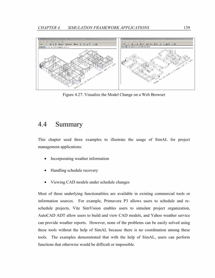
CHAPTER 4. SIMULATION FRAMEWORK APPLICATIONS
139
Figure 4.27: Visualize the Model Change on a Web Browser
4.4 Summary
This chapter used three examples to illustrate the usage of SimAL for project
management applications:
• Incorporating weather information
• Handling schedule recovery
• Viewing CAD models under schedule changes
Most of these underlying functionalities are available in existing commercial tools or
information sources. For example, Primavera P3 allows users to schedule and re-
schedule projects, Vite SimVision enables users to simulate project organization,
AutoCAD ADT allow users to build and view CAD models, and Yahoo weather service
can provide weather reports. However, none of the problems can be easily solved using
these tools without the help of SimAL because there is no coordination among these
tools. The examples demonstrated that with the help of SimAL, users can perform
functions that otherwise would be difficult or impossible.

Chapter 5
A Question Answering System for Project Management Applications
The usage of computer applications in the engineering and construction industry has
steadily increased over the years, as has the complexity of many software applications. It
is difficult for project personnel to become familiar with these ever-increasingly complex
tools. Furthermore, the causes of many practical problems, such as project delays or
escalating costs, are often not obvious from the outputs of these tools. A question
answering system can potentially provide a means to directly extracting answers from
these computer outputs. This chapter examines various issues involved in building such a
question answering system. The mechanisms of utilizing information in the knowledge
base for question understanding are explored. A prototype question answering system
has been built and tested to illustrate the potential usefulness of such a system for project
management applications [22].
CHAPTER 5. A QUESTION ANSWERING SYSTEM
141
5.1 Introduction
Natural language processing (NLP) technologies have been used in many applications.
Examples include database access [73, 101], machine translation [91], data extraction
from text [51], information retrieval [9], and text categorization/summarization [45].
Applications of all these types may be developed for deployment in the project
management domain.
In this chapter, we focus on the use of NLP technologies to help answer questions based
on semi-structured data generated from project management tools. This application is
closely related to research in data extraction from text and database access. A
combination of information retrieval and NLP technologies provides a powerful tool. For
example, project personnel use software tools for scheduling, cost estimating, and
reporting purposes. However, to discover the reasons why certain activities delay a
project or increase project costs, human expertise is needed to browse through and
examine a significant amount of output data. Using NLP technologies, it is possible to
convert natural questions into query expressions, so that such information can be
obtained from the software output. Data from various tools can be extracted, converted
into structured or semi-structured formats, and even stored in a database. Query results
for semi-structured data can then be used to generate answers (again using NLP) which
may not have been obvious from the raw output of the software.
The main objective of this work is to develop QAPM (A Question Answering System for
Project Management Applications), a prototype framework for an NLP based system for
extracting useful information from semi-structured pieces of text. QAPM is implemented
as a prototype system containing knowledge and information from the domain of
construction project management. The outputs from various computer applications are
encoded using domain specific ontology standards, such as ifcXML [59]. QAPM is then
able to extract useful information from these semi-structured texts, which would
otherwise not be obvious or possible to obtain directly from these applications. QAPM is

CHAPTER 5. A QUESTION ANSWERING SYSTEM
142
implemented as a QA (question answering) system that can assist project personnel in
making inferences about the project, based on information obtained from various project
management tools.
Various question answering systems have been developed in the past. For instance, there
have been many efforts made to develop natural language interfaces to databases.
Androutsopoulos et al. [4] discussed various methods and solutions available in
translating natural questions to database queries. Although some solutions seem
promising in a narrowly defined domain, it is difficult to apply these technologies to
construction projects, where database interfaces are not typically supported by the
application software. Callison-Burch and Shilane [20] developed a question answering
system to obtain information about a family tree. This system used the Knowledge
Interchange Format (KIF) [43] files as the knowledge representation system, and used a
Java-based Theorem Prover (JTP) [38] to infer answers. To develop such a system, a
knowledge base needs to be created manually, which makes it difficult to generalize the
system to other domains. Even within the same domain, this system may not scale well
over a number of individual projects, since a knowledge base needs to be created
manually for each project. Zajac [105] used a more general ontology-based semantic
approach for question answering. Both the questions and source texts are parsed into
semantic expressions. However, this approach assumes that the source texts are
expressed in natural sentences, from which semantic information can be extracted; thus it
cannot be directly applied to the project management domain, where information is
stored in various internal formats, either in plain text files or in semi-structured data files.
Our work aims to develop a question answering system, which is scalable over different
projects and considers the non-homogenous characteristics of project information.
Specifically, we take advantage of current developments in query languages for XML
data and the industry-based ontology standards.
The main contribution of QAPM is in the area of using non-document based retrieval of
information by combining information from multiple sources. This is mainly

CHAPTER 5. A QUESTION ANSWERING SYSTEM
143
accomplished by utilizing domain-specific ontologies in ifcXML. The fact that we use
NLP techniques to convert questions into a formal pattern matching language means that
our work also has important implications for User Interfaces in engineering domain
software. Most of the effort in NLP so far has been in the area of interacting with
documents in natural sentences; QAPM, however, takes into account domain-specific
issues, which makes it much more relevant and effective [29]. The lessons and
experiences gained from work on domain-independent fact based questions do not
necessarily ensure an effective QA system in specialized domains [29] such as project
management.
This chapter is organized as follows. Section 5.2 briefly reviews related technologies,
such as XML query languages and engines, POS tagging and chart parsing tools, and
WordNet, which are employed to develop the question answering system. Section 5.3
discusses the issues of knowledge representation and organization. Section 5.4 describes
the process of parsing and understanding questions; we discuss in detail how to utilize the
ifcXML schema and existing ifcXML files in the knowledge base to help understand
questions. In Sections 5.5 and 5.6, we briefly discuss how to search for answers in the
knowledge base and how to generate answers, respectively. Section 5.7 describes the
prototype framework and system implementation of QAPM. An example demonstration
of QAPM is presented in Section 5.8. Finally, Section 5.9 summarizes the status of the
current development and discusses future work.
5.2 Related Technologies
Many recent and current developments, such as ontology standards, query languages,
language parsers and information retrieval, can be employed to build a question
answering system. In this work, various technologies are used, including XQuery [95],

CHAPTER 5. A QUESTION ANSWERING SYSTEM
144
GNU Kawa’s Qexo [16], a POS tagging tool [82], a chart parsing tool [53] and WordNet
[36]. The following briefly describe these related technologies.
5.2.1 XML Query Language
XML query languages are designed to query information from XML files. Many XML
query languages are available, such as XQL [76], XML-QL [93], LOREL [1], Xpath
[94], and XQuery [95]. The query capability of XQL is limited at its current state, while
the research on LOREL is no longer active. In contrast, XQuery, based on XML-QL and
Xpath, is a full-featured query language and is emerging as a standard. Our initial
investigation shows that XQuery is an appropriate language for our prototype
implementation of a question answering system.
XQuery [95] is an XML query language jointly defined by the XML Query Working
Group and the XSL Working Group and is designed to be applicable to all types of XML
data sources. XQuery uses a syntax similar to SQL. For example, the following XQuery
sentence can be utilized to query the start date of the activity ELPV (Eng Layout &
Physical Ver_n):
for $ws in document("tuto.xml")//WorkSchedule
where $ws/@identifier = "ELPV"
return $ws/@startTime
5.2.2 XML Query Engine
Although XQuery is still in its W3C Working Draft version, many vendors have
implemented XQuery, such as Xquench [86], XQEngine [35], Galax [83], and GNU
Kawa Qexo [16]. In this work, we employ the GNU Kawa Qexo as the query engine
because of its high performance and easy usage, as well as its availability as open source.

CHAPTER 5. A QUESTION ANSWERING SYSTEM
145
Qexo is an open source project and a partial implementation of the XML query language
from GNU Kawa [16]. There are two ways to use Qexo. Qexo can be used in an
interactive environment, in which users can input query sentences at the command line.
In addition, Qexo can also compile XQuery sentences into Java byte codes, which
significantly improves the query efficiency. In this work, the latter approach is adopted;
XQuery expressions are compiled into Java byte codes to automate the process of answer
searching.
5.2.3 POS Tagging and Chart Parsing Tools
Part-Of-Speech (POS) tagging is designed to label each word in a sentence with its
appropriate part of speech. For instance, the word “finish” in the sentence, “When did
the project finish?” should be labeled as a verb. There are many POS tagging tools
available. QAPM employs ICOPOST [82], which is a set of free POS taggers written in
the C language.
A grammar parser is used to recognize the structure and organization of words in a
sentence. Among many available grammar parsers is a context-free grammar parser,
which assumes that phrases with the same part of speech can be interchangeable
regardless of the specific context. In QAPM, we have used the context-free grammar
chart parser developed at Stanford University [53]. The chart parser takes a grammar file
and a lexicon file. All possible parses, together with the best parses based on the
probability analysis, will be output as the parsing results.
5.2.4 WordNet
Developed by the Cognitive Science Laboratory at Princeton University [36], WordNet is
a lexical reference system, in which words are organized into synonym sets. WordNet
can be used online; it can also be installed and used on different platforms, including
CHAPTER 5. A QUESTION ANSWERING SYSTEM
146
Microsoft Windows and Unix environments. WordNet can help a question answering
system to identify synonyms. For example, verbs “start” and “begin” will be recognized
as synonyms by WordNet. The synonym information can be used to help match a
question with an appropriate rule, as we will discuss in Section 5.4.4.
5.3 Knowledge Representation and Organization in QAPM
5.3.1 Knowledge Representation using ifcXML
Knowledge representation is crucial in building a question answering system. Ideally, the
knowledge base should be built automatically, based on the existing information in the
domain. In the project management domain, project information in various applications
is usually stored in different internal formats. As discussed in previous chapters,
wrappers were built to retrieve project information from various sources and to convert
the information into standard formats [23, 25]. Many ontology standards exist in the
A/E/C domain, such as STEP and IFC/ifcXML. These ontology standards provide
standard terms and, often, relationships among the terms. In this research, we use
ifcXML as the knowledge representation format. Project information from various
applications can be extracted and translated into ifcXML files.
IfcXML is emerging as an industry standard and has many advantages for adoption as a
knowledge representation format. First, ifcXML provides many of the terms and
relationships commonly used in project management applications [59]. In addition,
ifcXML provides XML-based schemas, which are easy for querying and transferring on
the Internet. Second, as discussed earlier, there are many existing tools that can be used
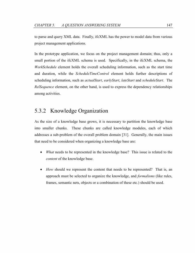
CHAPTER 5. A QUESTION ANSWERING SYSTEM
147
to parse and query XML data. Finally, ifcXML has the power to model data from various
project management applications.
In the prototype application, we focus on the project management domain; thus, only a
small portion of the ifcXML schema is used. Specifically, in the ifcXML schema, the
WorkSchedule element holds the overall scheduling information, such as the start time
and duration, while the ScheduleTimeControl element holds further descriptions of
scheduling information, such as actualStart, earlyStart, lateStart and scheduleStart. The
RelSequence element, on the other hand, is used to express the dependency relationships
among activities.
5.3.2 Knowledge Organization
As the size of a knowledge base grows, it is necessary to partition the knowledge base
into smaller chunks. These chunks are called knowledge modules, each of which
addresses a sub-problem of the overall problem domain [31]. Generally, the main issues
that need to be considered when organizing a knowledge base are:
• What needs to be represented in the knowledge base? This issue is related to the
content of the knowledge base.
• How should we represent the content that needs to be represented? That is, an
approach must be selected to organize the knowledge, and formalisms (like rules,
frames, semantic nets, objects or a combination of these etc.) should be used.

CHAPTER 5. A QUESTION ANSWERING SYSTEM
148
Knowledge Base
Schedule Cost Resource
09/01/2001
06/01/2001
03/01/2001
......
Figure 5.1: A Context Tree For Knowledge Organization
For project management applications, the knowledge base can be organized as a set of
knowledge modules, each representing a sub-domain, such as schedule, cost,
organizational model, etc. Meta-knowledge (i.e. knowledge about knowledge) is then
defined to guide the processing of the facts encoded in the knowledge base; in other
words, the meta-knowledge can help a question answering engine search for relevant
information. In QAPM, the meta-knowledge is encoded as sets of patterns, which serve
as the indices to different knowledge modules. When a question is posed, these patterns
are used to identify the relevant knowledge modules from which to retrieve the answer.
Figure 5.1 shows a schematic representation of the knowledge base. A project contains
information from several sub-disciplines, each of which usually comes from a
corresponding project management application. Moreover, within a sub-discipline,
information about different stages of the project can be stored in the knowledge base.

CHAPTER 5. A QUESTION ANSWERING SYSTEM
149
5.4 Parsing and Understanding Natural Questions
Understanding natural questions is rather difficult for computer applications, partly due to
the fact that there can be too many variations of natural language questions. Even if we
limit our research to a small predefined domain, for instance, the project scheduling
domain, there are still significant variations of possible questions, such as:
1. When did the PouringConcrete activity start?
2. Why should the PouringConcrete activity start before ErectingBeams?
3. Which subcontractor submitted scheduling changes yesterday?
Although all these questions are (1) syntactically correct; (2) semantically sound; and (3)
within the project scheduling domain, not all of these questions can be answered from the
knowledge base. For example, we may not have information for questions 2 and 3 in our
ifcXML files. For a practical question answering system, questions from users can be
either syntactically incorrect, semantically unsound, or both.
5.4.1 Analyzing ifcXML Trees
The ifcXML schema can be utilized to facilitate the understanding of questions. Using
the information in the schema, QAPM can predict what kind of questions it can answer.
We can safely ignore the questions with no answers in the knowledge base; in other
words, we do not need to understand the exact meanings of many questions that we
cannot answer from the existing knowledge. A preliminary analysis of such questions
may be enough to discard them. For example, for the question “How many governors of
California have been democrats during the past 50 years?” after a preliminary analysis,
we know that no rule in the knowledge base matches this question; thus, there is no need
to further analyze the exact meaning of the question.

CHAPTER 5. A QUESTION ANSWERING SYSTEM
150
To utilize the ifcXML schema, the first step is to analyze the tree structures of ifcXML
files. We have developed a Java program, which can analyze all the elements, attributes,
and relationships in our ifcXML files. Based on the analysis, we can predict possible
questions that we can answer and express the questions as rules. Each rule contains one
relation word and several parameters, such as the rules (duration activity) and (finish
activity). The rule (duration activity) means that an activity lasts a specific number of
days, while the rule (finish activity) specifies the finish date of the activity. Usually, the
first word in the rule specifies the relation, while the remaining words represent the
parameters of the rule. Figure 5.2 shows part of the tree structure of the ifcXML schema
about project scheduling. The leaf nodes are attributes, while all other nodes are
elements.
Root(ifcXML-2x_Final)
Project WorkScheduleGroup
TaskGroup
RelSequenceGroup
WorkSchedule Task RelSequence
id
startDate
description relatingProcess ......
...id
duration ...
Figure 5.2: Tree Structure of IfcXML Files
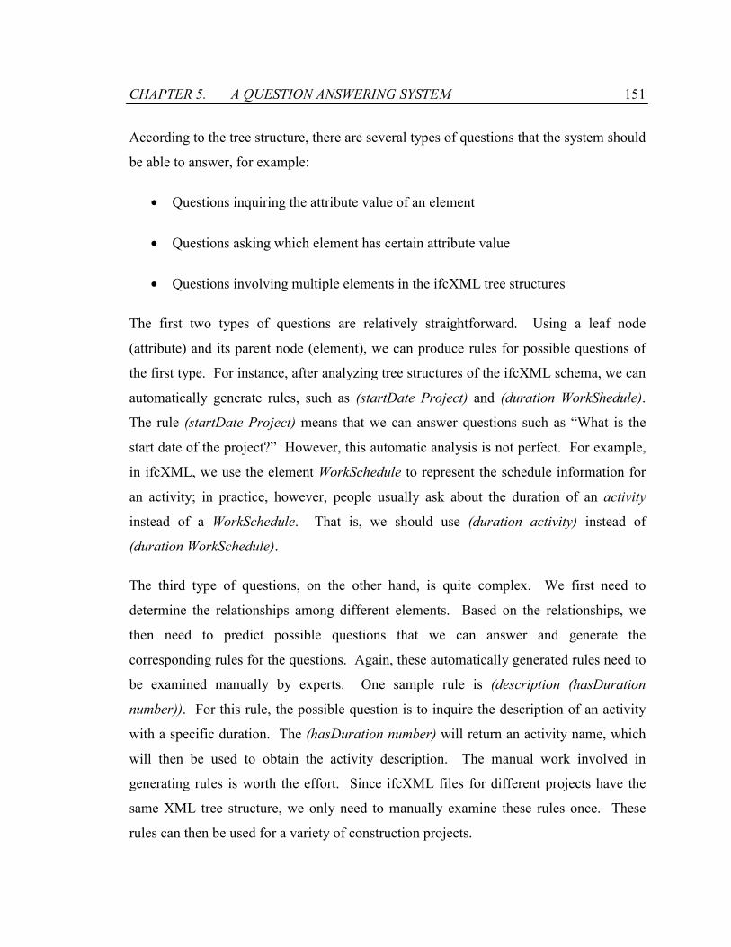
CHAPTER 5. A QUESTION ANSWERING SYSTEM
151
According to the tree structure, there are several types of questions that the system should
be able to answer, for example:
• Questions inquiring the attribute value of an element
• Questions asking which element has certain attribute value
• Questions involving multiple elements in the ifcXML tree structures
The first two types of questions are relatively straightforward. Using a leaf node
(attribute) and its parent node (element), we can produce rules for possible questions of
the first type. For instance, after analyzing tree structures of the ifcXML schema, we can
automatically generate rules, such as (startDate Project) and (duration WorkShedule).
The rule (startDate Project) means that we can answer questions such as “What is the
start date of the project?” However, this automatic analysis is not perfect. For example,
in ifcXML, we use the element WorkSchedule to represent the schedule information for
an activity; in practice, however, people usually ask about the duration of an activity
instead of a WorkSchedule. That is, we should use (duration activity) instead of
(duration WorkSchedule).
The third type of questions, on the other hand, is quite complex. We first need to
determine the relationships among different elements. Based on the relationships, we
then need to predict possible questions that we can answer and generate the
corresponding rules for the questions. Again, these automatically generated rules need to
be examined manually by experts. One sample rule is (description (hasDuration
number)). For this rule, the possible question is to inquire the description of an activity
with a specific duration. The (hasDuration number) will return an activity name, which
will then be used to obtain the activity description. The manual work involved in
generating rules is worth the effort. Since ifcXML files for different projects have the
same XML tree structure, we only need to manually examine these rules once. These
rules can then be used for a variety of construction projects.

CHAPTER 5. A QUESTION ANSWERING SYSTEM
152
5.4.2 Tagging Questions
The Part-Of-Speech (POS) tagger is used to provide POS information for individual
words. For example, using the POS tagger, QAPM can find out whether a word is a noun
or verb. The POS information can be used to help understand the meanings of words. In
particular, it can help us identify whether or not a word is a potential relation word or a
parameter in a rule.
Questions need to be processed before we can tag them. In particular, we need to
separate the words and punctuation marks in the questions. The following examples show
some sample tagging results:
When WRB will MD activity NN ID100 NN start NN ? .
How WRB many JJ successors NNS does VBZ activity NN ELPV NNP have VBP ?
When WRB will MD ELPV NNP end VB ? .
Here NN (NN, NNS or NNP) represents a noun, VB (VB, VBZ or VBP) represents a
verb, WRB represents a wh-adverb, JJ represents an adjective, and MD represents a
modal word. We can see that the POS tagger does not always provide the correct POS
information. For example, it tags the word “start” in the first sentence as a noun, while it
is actually a verb. Nonetheless, the POS information provides a good basis for
understanding questions.
5.4.3 Parsing Questions
QAPM uses a context-free grammar chart parser for parsing questions. To use the chart
parser, we first need to create both a grammar file and a lexicon file. While it is possible
to write a grammar file for questions in the project management domain, it is a tedious, if
not an impossible task, to create a lexicon file for all possible questions, since the lexicon
file must contain all the words which can appear in the questions.

CHAPTER 5. A QUESTION ANSWERING SYSTEM
153
S -> WRB MD NP VP ? %%0.1S -> WP MD NP VP ? %%0.1NP -> NN %%0.1NP -> NNS %%0.1NP -> NNP %%0.1VP -> VB %%0.1VP -> VBD %%0.1
……
Figure 5.3: Grammar File for the System
We can extract a grammar file from the Penn Treebank, a human-annotated corpus
consisting of over 4.5 million words of American English [63]. However, the extracted
grammar file is huge, while most of the grammar rules are not useful for questions. The
size of grammar rules will significantly affect the parsing process. On the other hand, a
much smaller grammar file is possible for questions within a small domain. As a result, a
grammar file for questions in the project management domain was developed. Figure 5.3
shows part of the grammar file, which is largely based on a heuristic observation. As an
example, the grammar rule “S -> WRB MD NP VP ? %%0.1” indicates that a question
sentence can be rewritten into a wh-adverb, a modal verb, a noun phrase, and a verb
phrase. The grammar rule “NP -> NNS %%0.1” indicates that a noun phrase can be
rewritten as a singular noun, in which the number 0.1 represents the probability that a
noun phrase will be rewritten as a singular noun. The probability values are not used by
the context-free chart parser in this work; rather, these values are provided to conform to
the required format, since other probabilistic context-free grammar parsers need these
probability values.
For the lexicon file, we can also extract lexicons from the Penn Treebank. Developed by
the Stanford Natural Language Process Group, the standalone program ExtractPTBRules
[53] can be used to extract lexicon files from a collection of the Penn Treebank sentences.
However, even if we extract lexicons from a large collection of documents, many words
in the questions may still not be included in the lexicon file; as a result, the chart parser
will have difficulties in parsing the question.

CHAPTER 5. A QUESTION ANSWERING SYSTEM
154
A simple but effective approach is to utilize the POS tagging results. We can
dynamically generate a lexicon file based on the tagging results. Obviously, all words in
the question will appear in the lexicon file. Assuming that the question is syntactically
correct, the chart parser will always find a parse for a question. Figure 5.4 illustrates this
approach.
Once the grammar and lexicon files are ready, we can use the chart parser to parse the
questions. All possible parses, together with their corresponding probability values, will
be generated. In addition, the best parse is also available. Figure 5.5 illustrates the
process of generating a lexicon file for the question, while Figure 5.6 shows the parsing
results of an example question.
Natural Question
Lexicon File
Grammar File
ParseInformation
POSInformation
TrigramTagger
ChartParser
Figure 5.4: Tagging and Parsing Questions
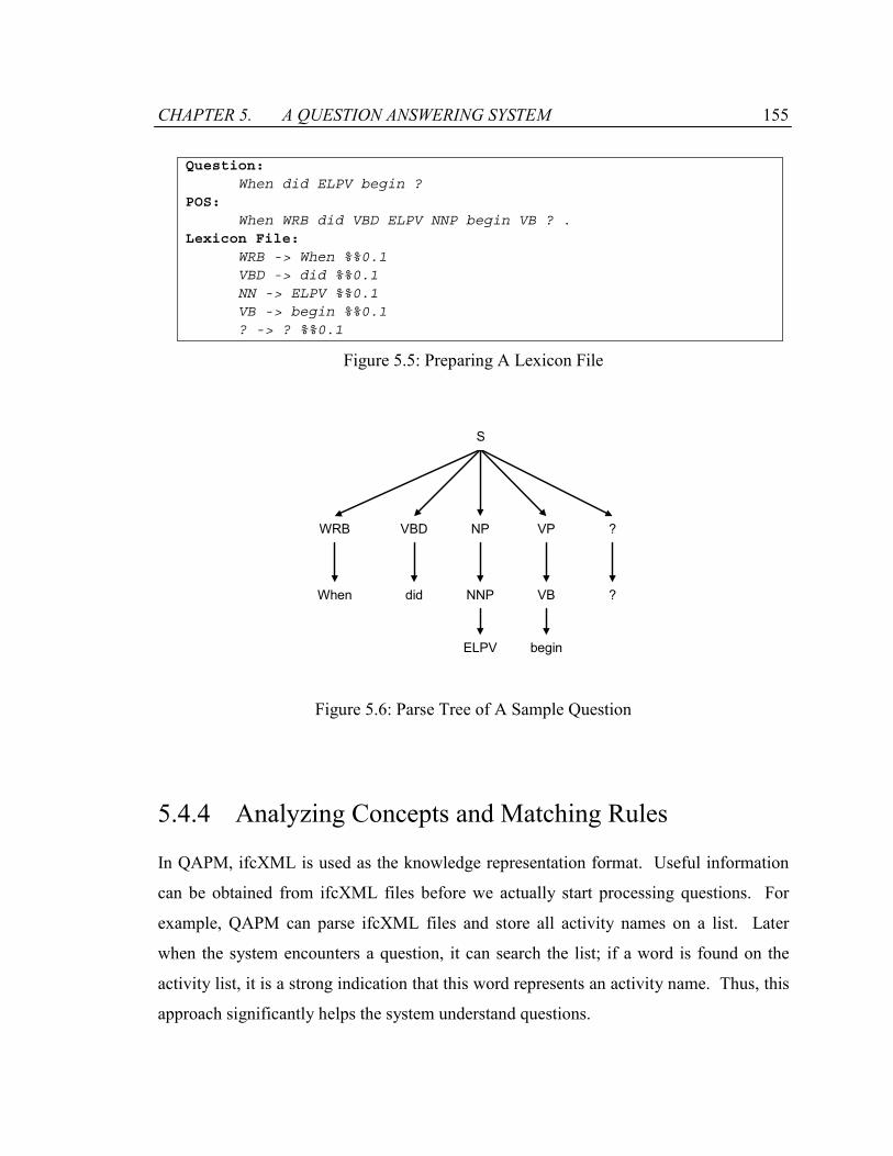
CHAPTER 5. A QUESTION ANSWERING SYSTEM
155
Question:When did ELPV begin ?
POS:When WRB did VBD ELPV NNP begin VB ? .
Lexicon File:WRB -> When %%0.1VBD -> did %%0.1NN -> ELPV %%0.1VB -> begin %%0.1? -> ? %%0.1
Figure 5.5: Preparing A Lexicon File
WRB VBD NP
NNP
VP
VBWhen did
ELPV begin
?
?
S
Figure 5.6: Parse Tree of A Sample Question
5.4.4 Analyzing Concepts and Matching Rules
In QAPM, ifcXML is used as the knowledge representation format. Useful information
can be obtained from ifcXML files before we actually start processing questions. For
example, QAPM can parse ifcXML files and store all activity names on a list. Later
when the system encounters a question, it can search the list; if a word is found on the
activity list, it is a strong indication that this word represents an activity name. Thus, this
approach significantly helps the system understand questions.

CHAPTER 5. A QUESTION ANSWERING SYSTEM
156
Earlier, we discussed possible questions that QAPM can answer from the knowledge
base, and how to express them in rules. We also discussed how to obtain the POS and
parsing information for the questions. Based on the information above, we can analyze
the concepts in the questions and match the questions with corresponding rules. Usually,
the most important words for understanding questions are the question words, the nouns,
and the verbs.
• Question words, such as when, what, why, how and does, determine the type of
the question; in addition, these words also imply what kind of answers users
expect.
• Nouns usually correspond to object names, such as activity names, in ifcXML
files. Sometimes, nouns can also be used to express relations in the rules. For
example, in the following question:
What is the start date of Sim_Gates?
The noun phrase “start date” corresponds to the relation “start” in the rule (start
activity).
• Verbs usually imply the rule to which a question should be categorized. For
instance, in the following sentence:
When does the task Sim_Gates end?
The verb “end” is a strong indication that QAPM should categorize this sentence
into the rule (end activity), while the word “Sim_Gates” corresponds to the
activity parameter in the rule.
In addition, WordNet is used by QAPM to categorize synonyms into the correct rules.
For example, to ask the start date of an activity, we may use either start or begin. Using
WordNet, QAPM can categorize both situations into the rule (start activity).
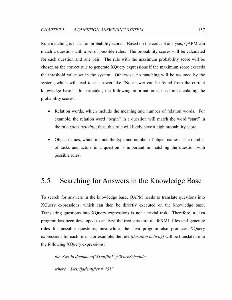
CHAPTER 5. A QUESTION ANSWERING SYSTEM
157
Rule matching is based on probability scores. Based on the concept analysis, QAPM can
match a question with a set of possible rules. The probability scores will be calculated
for each question and rule pair. The rule with the maximum probability score will be
chosen as the correct rule to generate XQuery expressions if the maximum score exceeds
the threshold value set in the system. Otherwise, no matching will be assumed by the
system, which will lead to an answer like “No answer can be found from the current
knowledge base.” In particular, the following information is used in calculating the
probability scores:
• Relation words, which include the meaning and number of relation words. For
example, the relation word “begin” in a question will match the word “start” in
the rule (start activity); thus, this rule will likely have a high probability score.
• Object names, which include the type and number of object names. The number
of tasks and actors in a question is important in matching the question with
possible rules.
5.5 Searching for Answers in the Knowledge Base
To search for answers in the knowledge base, QAPM needs to translate questions into
XQuery expressions, which can then be directly executed on the knowledge base.
Translating questions into XQuery expressions is not a trivial task. Therefore, a Java
program has been developed to analyze the tree structure of ifcXML files and generate
rules for possible questions; meanwhile, the Java program also produces XQuery
expressions for each rule. For example, the rule (duration activity) will be translated into
the following XQuery expressions:
for $ws in document("$xmlfile1")//WorkSchedule
where $ws/@identifier = "$1"

CHAPTER 5. A QUESTION ANSWERING SYSTEM
158
return $ws/@duration
There are two parameters in the XQuery expressions. The first parameter $xmlfile1
appears in most rules; it represents one of the ifcXML files in the current project. The
second parameter $1 corresponds to the activity name in the rule.
When a question is parsed, QAPM categorizes it into a rule, based on the syntactic and
semantic information of the question. As an example, the question “What is the duration
of the task Sim_Gates?” will be categorized into the rule (duration activity), where the
value of the parameter activity is Sim_Gates. Suppose the corresponding ifcXML file in
the current project is p3_tuto.xml, the following XQuery expressions will be generated
for this question:
for $ws in document("p3_tuto.xml")//WorkSchedule
where $ws/@identifier = "Sim_Gates"
return $ws/@duration
The XQuery expressions are then compiled into Java byte codes by the Qexo query
engine. Finally, the generated codes are used to search the knowledge base for the
answer.
5.6 Answer Generation
The answer generator first needs to parse the query results from the query engine. In
addition, it needs to consider different types of questions. For instance, for a wh-
question, a question with specific information is usually expected. For a how many
question, on the other hand, we should give a specific number. In contrast, for a yes or no
question, a yes or no answer is usually sufficient. In most cases, for a wh-question, if the
XQuery engine cannot find any result, it is adequate to provide an answer such as “Sorry,

CHAPTER 5. A QUESTION ANSWERING SYSTEM
159
we cannot find the answer in the knowledge base.” In the current prototype, we provide
only short answers to most questions, for example:
Ask QAPM> when will the task STF terminate?
……
QAPM Ans> 1/4/99
Alternatively, QAPM can provide an answer in full sentences, such as “STF will
terminate on 1/4/99.” This approach, however, increases the implementation complexity
without providing additional information. Rather, using a short answer, such as “1/4/99,”
is sufficient in most cases.
5.7 The Framework and Implementation of QAPM
A question answering system usually includes the following components: knowledge
representation, question understanding, answer searching, and answer generation. Figure
5.7 illustrates the overall framework of QAPM. As shown in Figure 5.7, ifcXML is used
to represent knowledge, while the XML query engine is employed for information query.
In the first and most critical step, QAPM parses and understands natural language
questions. These questions are then converted into XQuery expressions, which are
executed by the XQuery engine. The query results are finally utilized by the generator to
produce answers.

CHAPTER 5. A QUESTION ANSWERING SYSTEM
160
NaturalQuestions
XML Query Engine
Answers
Knowledge Base(ifcXML files)
Primavera P3
Wrapper Wrapper Wrapper
NLPGenerator
NLPParser
Translateto XQuery
Invoking Engine
MS Project Vite SimVision
Figure 5.7: The Framework of QAPM
Information in the knowledge base comes from various sources, such as the Primavera
Project Planner (P3), Microsoft Project, and Vite SimVision. Wrappers are employed to
communicate with different software applications, while the invoking engine is used to
execute these wrappers.
The detailed question answering process is illustrated in Figure 5.9. The rule generation
process involves manual examination; however, this examination can be done by the
experts in advance. At runtime, QAPM first tags and parses the question using existing
NLP tools. The result is the basis for further analysis. In particular, the object names in
the ifcXML files are used to help understand questions. In addition, rules, which are
generated from XML trees and manually examined, are also used to help understand
questions. Based on the analysis, QAPM matches the question against potential rules. If

CHAPTER 5. A QUESTION ANSWERING SYSTEM
161
no match is found, there is probably no answer for the question based on the existing
knowledge. Otherwise, QAPM conducts further analysis and generates answers.
QAPM is developed in Java. Various Java classes have been developed for different
tasks, such as tagging questions and checking synonyms. External programs, including
XQuery engine and WordNet, are invoked via Java system calls, and results from these
external programs are stored either in temporary files or Java InputStreams.
ifcXMLschema ifcXML files
Analyze Tree toPredict PossibleQuestion Types
Extract ObjectNames (task,
actor, etc.)ManualExamination
Rules
Natural Questions
QuestionUnderstanding
Match Rule ?
Genertaing XqueryExpression
Answer Generation
No Answer
NLP Processing(Tagging, Parsing)
Synonym Analysis(Wordnet, etc.)
Invoke XQueryEngine
Yes No
Figure 5.8: Detailed Process of the QAPM Question Answering System

CHAPTER 5. A QUESTION ANSWERING SYSTEM
162
5.8 Sample Demonstration of QAPM
5.8.1 Example Project used in the Demonstration
We test QAPM on a chip design project, which is a tutorial example in Vite SimVision
[92]. The project involves both the design and the foundry staff to accelerate the design
and construction of a new chip. The goal of the project is to design and fabricate a chip
set for a new Personal Digital Assistant (PDA) product within a tight schedule. There are
12 activities in this project. Among the 12 activities are three milestone activities: “Start
Project,” “Ship Tapes to Foundry” and “Fab, Test and Deliver.” The activity
“Design_Coordination” maintains the overall control of the project.
Figure 5.10 shows the Gantt Chart of the Project in Primavera P3, where activities on the
critical path are shown in dark color (red). Detailed scheduling information, such as the
start dates, durations, and finish dates of individual activities, is available in Primavera
P3. In addition, dependency relationships among these activities are also included. A
wrapper, as described in Chapters 2 and 3, has been developed to retrieve information
from the Primavera Project Planner (P3) and to convert it into an ifcXML file [24, 25].
Figure 5.9: The Gant Chart of the Chip Design Project in Primavera P3

CHAPTER 5. A QUESTION ANSWERING SYSTEM
163
<WorkScheduleGroup><WorkSchedule identifier="ID100" duration="18.0" freeFloat="0.0"totalFloat="0.0" startTime="11/17/1998" finishTime="12/10/1998"/>
</WorkScheduleGroup><TasksGroup>
<Task taskid="ID100" description="Assemble and verify_RTL"/><Task taskid="ID700" description="FullChipSynth"/>
</TasksGroup><RelSequenceGroup>
<RelSequence id="depend0" relatingProcess="ID100"relatedProcess="ID170" timeLag="0.0"sequenceType="after-start"/>
</RelSequenceGroup>
Figure 5.10: Generated Sample ifcXML File from Primavera P3
Figure 5.11 shows the resulting ifcXML file from the Primavera Project Planner. In this
example, the scheduling information is expressed using WorkSchedule, Task and
RelSequence elements. In particular, a Task element in ifcXML maps to an activity in a
project schedule. The WorkSchedule element is associated with the corresponding
activity by using the same identifier as its identifier attribute. Similarly, the RelSequence
element, which depicts the dependency relationships among activities, is associated with
the predecessor and successor activities through its ‘relatedProcess’ and
‘relatingProcess’ attributes.
Figure 5.12 shows the chip design project in Vite SimVision. Actors and supervision
relationships are shown in the top half of the display, while activities and dependency
relationships are shown in the bottom half. Various aspects of the project, such as
supervision, task assignment, communication and rework information, are represented
using links in different colors in Vite SimVision. Again, a wrapper, as described in
Chapters 2 and 3, has been developed to retrieve organization information from Vite
SimVision and convert it into the corresponding ifcXML file. To represent the
information in Vite SimVision, extensions are introduced in ifcXML. For example, we

CHAPTER 5. A QUESTION ANSWERING SYSTEM
164
introduce the Rework element, which is not included in the current ifcXML schema, to
represent the rework information among activities. The XML structure, <Rework
id="REW100" relatingTask="WVSB" relatedTask="PCAFP" />, indicates that the
failure of the task WVSB (“Write-Verify-Synth_B1RTL”) will lead to the rework of the
task PCAFP (“Partition Chip and Floor Planning”).
Figure 5.11: The Chip Design Project in Vite SimVision

CHAPTER 5. A QUESTION ANSWERING SYSTEM
165
5.8.2 Working Scenario
When invoked, QAPM first initializes and displays the welcome messages. First, users
can choose to load any project in the database. The following command loads the TUTO
project into the runtime environment:
Ask QAPM> load tuto
Currently, the project tuto has been loaded
There are 2 ifcxml files about the project :p3_tuto.xml, vite_tuto.xml
The ifcXML files will then be analyzed by QAPM, i.e., to extract object names. Once
the program has finished the initialization process, it is ready to answer questions.
QAPM first analyzes questions and converts them into XQuery expressions. The
XQuery engine then executes the XQuery expressions based on the current knowledge
base. The XQuery results are then parsed and presented to the user.
QAPM can answer various questions about project schedule, such as the start date, end
date, duration, successors, and predecessors of an activity. It ignores the tense of the
question. In addition, WordNet is used to identify synonyms. For example, in the
following question, QAPM will give the same answer if we use the word “start” instead
of “begin.”
Ask QAPM> when did Design_Coordination start? Convert to XQuery expressions ... for $ws in document("p3_tuto.xml")//WorkSchedule where $ws/@identifier = "DC" return $ws/@startTime XQuery Results: startTime="10/19/1998" QAPM Ans> 10/19/1998 Ask QAPM> what is the duration of the task Generate Test Vectors? Convert to XQuery expressions ... for $ws in document("p3_tuto.xml")//WorkSchedule

CHAPTER 5. A QUESTION ANSWERING SYSTEM
166
where $ws/@identifier = "GTV" return $ws/@duration XQuery Results: duration="2.0" QAPM Ans> 2.0 Ask QAPM> which activity succeeds Sim_Gates? Convert to XQuery expressions ... for $ws in document("p3_tuto.xml")//RelSequence where $ws/@relatingProcess = "SG" return $ws/@relatedProcess XQuery Results: relatedProcess="GTV" QAPM Ans> Generate Test Vectors
It is also possible to ask other questions about the project, such as task assignments,
supervision, costs, task uncertainties, and other information. Example usages are shown
as follows:
Ask QAPM> who is responsible for Develop Specification? Convert to XQuery expressions ... for $ts in document("vite_tuto.xml")//RelAssignsTasks where $ts/@relatingTask = "DS" return $ts/@relatedActor XQuery Results: relatedActor="HPM" QAPM Ans> HW Project Manager Ask QAPM> what is the hourly cost of Foundry layout engineer? Convert to XQuery expressions ... for $ws in document("vite_tuto.xml")//Actor where $ws/@id = "FLE" return $ws/@salary XQuery Results: salary="50.00" QAPM Ans> 50.00 Ask QAPM> which task does sim_Gates need to communicate with? Convert to XQuery expressions ... for $cs in document("vite_tuto.xml")//Communication where $cs/@relatedTask = "sim_Gates" return $cs/@relatingTask XQuery Results: relatingTask="DC"

CHAPTER 5. A QUESTION ANSWERING SYSTEM
167
QAPM Ans> Design_Coordination
In addition, the system can answer more complex questions by combining the
information from the Primavera Project Planner and Vite SimVision. For example, to
answer the first question “which actors are involved with tasks on the critical path?” the
system searches from the Vite ifcXML file for task assignment information and searches
from the Primavera P3 file for critical path information.
Ask QAPM> which actors are involved with tasks on the critical path? Convert to XQuery expressions ... for $ws in document("p3_tuto.xml")//WorkSchedule, $rs in document("vite_tuto.xml")//RelAssignsTasks where $ws/@identifier = $rs/@relatingTask and $ws/@freeFloat="0.0" return $rs/@relatedActor XQuery Results: relatedActor="FT" relatedActor="LDT" relatedActor="HPM" relatedActor="FLE" relatedActor="LDT" relatedActor="FT" relatedActor="CA" QAPM Ans> Foundry test Logic design team HW Project Manager Foundry layout engineer Logic design team Foundry test Chip Architect Ask QAPM> which tasks on the critical path has the highest uncertainty? Convert to XQuery expressions ... for $ws in document("p3_tuto.xml")//WorkSchedule, $ts in document("vite_tuto.xml")//Task where $ws/@identifier = $ts/@taskid and $ws/@freeFloat="0.0" and $ts/@uncertainty="high" return $ws/@identifier XQuery Results: identifier="DS" QAPM Ans> Develop Specification Ask QAPM> when does the activity with highest priority start? Convert to XQuery expressions ... for $ws in document("p3_tuto.xml")//WorkSchedule, $ts in document("vite_tuto.xml")//Task where $ws/@identifier = $ts/@taskid and $ts/@priority = "high" return $ws/@startTime XQuery Results:

CHAPTER 5. A QUESTION ANSWERING SYSTEM
168
startTime="9/18/1998" QAPM Ans> 9/18/1998
5.8.3 Analysis of the Results
There are two basic approaches to evaluating a question answering system: on-line and
off-line evaluations [14]. For on-line evaluations, system answers are judged by humans,
while the answers in off-line evaluations are scored by an evaluation program against
standard references.
In this research, QAPM was tested on a selected set of questions in the project
management domain. It has been tested on the chip design project as well as a few
residential building projects and demonstrates reasonable accuracy. However, the
evaluation results depend on the selection of test questions as well as human judgement.
The types, complexities, and ranges of questions, the human judgements on generated
answers, the documents in the knowledge base, and other factors all affect the
performance of the system.
A standard evaluation program can save significant efforts in assessing a question
answering system. However, since the results from project management tools are often
stored in various internal formats, current evaluation programs cannot be directly applied
in this research due to the characteristics of the project management domain. For
example, Qaviar, an experimental evaluation program developed at the MITRE
Corporation, judges the response using human generated answer keys and focuses on the
Text REtrieval Conference (TREC) context [15]. E-Rater, an evaluation system
developed at ETS, is used to score essay questions of TOEFL takers [19].

CHAPTER 5. A QUESTION ANSWERING SYSTEM
169
5.9 Summary and Discussions
In this chapter, we present a framework for developing a question answering system in a
specific domain. An implementation of the QAPM framework for project management
applications was described. Taking domain-specific issues into account results in a much
more robust and effective system in specialized domains. Once rules were generated
from the ifcXML schema and examined by experts, QAPM requires no extra human
involvement in building the knowledge base for individual projects, thus demonstrating
the adaptability and scalability of the approach to different projects. Finally, using
information from the knowledge base, together with the syntactic and semantic analysis,
leads to better understanding of questions.

Chapter 6
Summary and Discussions
6.1 Summary and Contributions
This thesis addresses some important problems in the domain of project management,
and has developed a simulation access language (SimAL) and framework that can
provide additional services based on existing tools. Four main contributions are made in
this thesis.
• Extensions to the Process Specification Language (PSL)
We have investigated typical project management applications in the design and
construction domain to examine what kinds of extensions are necessary to use
PSL for project information exchange. Some of the suggested extensions have
been adopted in the PSL specification, and other extensions are used in our
research prototype. It is expected that some of these extensions will be
incorporated into PSL as part of the standards.

CHAPTER 6. SUMMARY AND FUTURE DIRECTIONS
171
• Data Exchange for Project Management Applications
With the increasing use of computer applications in project management, the
interoperability among these applications has become an important issue. In
particular, exchanging process information is important since project management
involves volumes of process information. Our research evaluates and
demonstrates the applicability of using PSL to exchange process information
among distributed computer applications in the project management domain. A
distributed data integration infrastructure has been prototyped and tested on a few
projects collaboratively between Glasgow Caledonian University in Scotland and
Stanford University.
• Consistency Checking and Constraint Scheduling
When project information is obtained from different applications, it is important
to maintain the consistency of process information among these applications.
Currently, no formal approach exists to solve the consistency checking problem.
This research proposes a formal mechanism to check inconsistencies, and the
method has been validated on a few example projects. In addition, large, complex
projects often involve numerous constraints. This thesis proposes a method to
express schedule constraints in PSL and to ensure the conformity of project
schedules to the constraints with the help of a logic-reasoning tool.
• Workflow Management and Decision Support
To handle changes in a project, users usually need information from different
sources to evaluate the impact on different aspects (e.g., costs and schedules) of
the project. The accessibility of such information is often precluded by network
communication and data integration details (e.g., various applications residing at
different locations and using different representations). The SimAL language and

CHAPTER 6. SUMMARY AND FUTURE DIRECTIONS
172
framework allows users to use a simple language to gather information from
heterogeneous sources and to simulate and compare different scenarios.
• A Question Answering System
A prototype question answering system QAPM has been developed to alleviate
users’ burden on browsing through volumes of data generated by different project
management tools. Emerging industry standards, such as ifcXML, are adopted as
the knowledge representation format to alleviate the manual effort to build a
knowledge base. The mechanisms of utilizing information in the knowledge base
are explored for question understanding.
6.2 Future Research
This thesis opens up a wide field of potential research and applications. While this thesis
has addressed many aspects of the problem in integrating, coordinating, and reusing
project management tools, it could only do so to a limited depth, and in a limited
application area. This section describes some of the important issues deemed valuable
for future research in simulation access and project management.
6.2.1 The Process Specification Language (PSL)
6.2.1.1 Exchanging Product and Process Information
This thesis discussed how to use PSL to exchange process information. In particular, we
elaborated on how to express scheduling information in PSL. As shown in Figure 6.1,
process information includes scheduling, resource, cost, and organization information.

CHAPTER 6. SUMMARY AND FUTURE DIRECTIONS
173
Currently, PSL is an on-going standard, and its capability in expressing process
information other than scheduling is still under-development.
In a typical project, not only process information but also product data are involved in
project management. PSL is not designed to model product data. Thus, to exchange
project information, ontology standards, which are capable of modeling product data, are
also needed. Example standards include IFC and STEP. However, further research is
needed to effectively integrate PSL with other product data standards.
Scheduling
Resource Cost
Organization
Figure 6.1: Typical Process Information in Project Management

CHAPTER 6. SUMMARY AND FUTURE DIRECTIONS
174
6.2.1.2 Constraint Scheduling using PSL
In this thesis, we have examined the potential of PSL in checking whether a schedule
meets various constraints. Constraint scheduling is a complex problem. For most
commercial project management tools, the Critical Path Method (CPM) is routinely used
to compute the start and finish times of activities. However, when resource leveling is
involved, finding the optimal (shortest feasible) schedule becomes much more difficult
and complex. Because of its logical representation, PSL may be useful in constraint
scheduling. Activities, resources, and constraints can be expressed in logical sentences
using PSL. Find an optimal constrained schedule can be viewed as a problem of seeking
the shortest project duration that also satisfies the constraints expressed in PSL.
6.2.2 The Simulation Access Language (SimAL) and
Framework
6.2.2.1 Decision-Support Capabilities of SimAL
Currently, the SimAL language provides some basic decision support capabilities to
allow users to specify, simulate, and compare scenarios. Each scenario may require a set
of actions executed by different project management tools. Decision-making, however,
may require further manipulating and analyzing the simulation results. Although separate
services can be developed to support decision making, the SimAL language currently
does not support aggregating and mining results from different computer applications.
Further research is needed to extend SimAL to support complex decision analysis.
6.2.2.2 Computational Capabilities of SimAL
The SimAL language is designed as a compositional language. In other words, SimAL
does not provide any computational capabilities; rather, users need to invoke other

CHAPTER 6. SUMMARY AND FUTURE DIRECTIONS
175
services to conduct computational tasks. While this design keeps the SimAL language
clean and simple, users are burdened with additional work even for simple calculations,
such as adding two numbers from the results generated by different computer
applications. It would be desirable to include some minimal computational capabilities
within the SimAL language.
6.2.2.3 Validation and Testing
We have applied a simulation access framework to integrate and coordinate distributed
project management software applications on a number of demonstration projects. The
framework has been tested on a few projects remotely between Glasgow Caledonian
University, Scotland and Stanford University. Future research is needed to validate the
framework. In particular, it would be desirable to deploy the prototype in a number of
engineering and construction companies and test the system in practice. Meanwhile,
although the project management software applications are selected primarily from the
design and construction industry, the SimAL language and framework are designed and
implemented with sufficient flexibility that the framework can be applied to other
domains.
6.2.3 The Question Answering System
We have developed a prototype question answering systems QAPM and have
demonstatted it on a few illustrative project. However, the grammar used for the chart
parser in the current implementation is based on a heuristic approach. A more complete
grammatical analysis of various questions may be required for a more robust system
Extending QAPM to handheld devices would provide further significant benefits for
project management. For example, although many handheld devices, such as Palm Pilots
and Pocket PCs, are often used by project members on construction sites, these devices
cannot run most project management applications, such as Vite SimVison, the Primavera

CHAPTER 6. SUMMARY AND FUTURE DIRECTIONS
176
Project Planner, and 4D Viewer. This incapability is due to their small amount of
memory and sub-optimal displays. A question answering system, on the other hand,
requires little memory or displaying abilities on the client device. With a question
answering system available, on-site personnel can simply input the question and get the
information back using handheld devices.
6.3 Conclusions
Some of the positive outcomes of this work are that the SimAL system may improve the
reusability and extend the applications of existing computer tools, help users gather
relevant project information, and assist users in comparing alternative scenarios.
The SimAL language and framework can help users integrate, coordinate, and reuse
existing project management tools. Different project management tools can be brought
together to solve tasks that otherwise would be difficult to handle by individual tools. In
addition, the SimAL system can help collecting relevant project information from
geographically distributed tools and project sites. Even though the tools may use
different internal data representations, the SimAL system allows users to view and update
project information using a simple, consistent language. Finally, the SimAL system can
help users to investigate and compare alternative scenarios. Different options can be
tested and evaluated by using the SimAL system to gather information from different
tools.
In conclusion, this thesis has demonstrated how a simulation access language (SimAL)
and framework can integrate different project management tools, coordinate them,
improve their reusability, and provide help in decision-making.

Bibliography
[1] S. Abiteboul, D. Quass, J. McHugh, J. Widom, and J. Wiener. "The Lorel Query
Language for Semistructured Data," International Journal on Digital Libraries,
1(1):68-88, 1997.
[2] B. Akinci, M. Fischer, R. Levitt, and R. Carlson. "Formalization and Automation
of Time-Space Conflict Analysis," Journal of Computing in Civil Engineering,
16(2):124-134, 2002.
[3] T. Andrews, F. Curbera, H. Dholakia, Y. Goland, J. Klein, F. Leymann, K. Liu, D.
Roller, D. Smith, S. Thatte, I. Trickovic, and S. Weerawarana. BPEL4WS
Specification: Business Process Execution Language for Web Services Version
1.1, http://www-106.ibm.com/developerworks/library/ws-bpel/, 2003.
[4] I. Androutsopoulos, G. D. Ritchie, and P. Thanisch. "Natural Language Interfaces
to Databases -- An Introduction," Journal of Natural Language Engineering,
1(1):29-81, 1995.
[5] A. Ankolekar, M. Burstein, J. R. Hobbs, O. Lassila, D. L. Martin, S. A. McIlraith,
S. Narayanan, M. Paolucci, T. Payne, K. Sycara, and H. Zeng. "DAML-S:
Semantic Markup for Web Services," Proceedings of the International Semantic
Web Working Symposium, Stanford, CA, 2001.

BIBLIOGRAPHY
178
[6] J. Antill and R. Woodhead. Critical Path Methods in Construction Practice, 2nd
Ed., John Wiley & Sons, Inc., New York, 1970.
[7] N. Apte and T. Mehta. UDDI: Building Registry-based Web Services Solutions,
Pearson Education, 2003.
[8] A. Arkin. Business Process Modeling Language, Business Process Management
Initiative, 2002.
[9] R. Baeza-Yates and B. Ribeiro-Neto. Modern Information Retrieval, Addison
Wesley Ltd, 1999.
[10] A. D. Birrell and B. J. Nelson. "Implementing Remote Procedure Calls," ACM
Transactions on Computer Systems, 2(1):39-59, 1984.
[11] B. C. Bjork. "Basic Structure of a Proposed Building Product Model," CAD,
21(2):71-78, 1989.
[12] A. Bosworth. "Developing Web Services," Proceedings of the International
Conference on Data Engineering, Heidelberg, Germany, pp. 477-481, 2001.
[13] D. Box, D. Ehnebuske, G. Kakivaya, A. Layman, N. Mendelsohn, H. Nielsen, S.
Thatte, and D. Winer. Simple Object Access Protocol (SOAP), W3C Note,
http://www.w3.org/TR/SOAP, 2000.
[14] E. J. Breck, J. D. Burger, D. House, M. Light, and I. Mani. "Question answering
from large document collections," Proceedings of AAAI Fall Symposium on
Question Answering Systems, North Falmouth, MA, pp. 26-31, 1999.
[15] E. J. Breck, J. D. Burger, L. Ferro, L. Hirschman, D. House, M. Light, and I. Mani.
"How to Evaluate Your Question Answering System Every Day and Still Get Real
Work Done," Proceedings of LREC-2000, the 2nd International Conference on
Language Resources and Evaluation, Athens, Greece, 2000.

BIBLIOGRAPHY
179
[16] P. Brothner. "Kawa: Compiling Scheme to Java," Proceedings of Lisp Users
Conference, Berkeley, CA, 1998.
[17] L. D. Brown. Managing Conflict Among Groups, Prentice-Hall, Inc., 1995.
[18] M. Burner. "The Deliberate Revolution Transforming Integration With XML Web
Services?," ACM Queue, 1(1):28-37, 2003.
[19] J. Burstein, K. Kukich, S. Wolff, C. Lu, and M. Chodorow. "Computer Analysis of
Essays," Proceedings of NCME Symposium on Automated Scoring, 1998.
[20] C. Callison-Burch and P. Shilane. A Natural Language Question and Answer
System, Stanford University, Stanford, CA, 2000.
[21] S. Chandrasekaran, G. Silver, J. Miller, J. Cardoso, and A. Sheth. "Web Service
Technologies and their Synergy with Simulation," Proceedings of the 2002 Winter
Simulation Conference (WSC'02), San Diego, CA, pp. 606- 615, 2002.
[22] J. Cheng, B. Kumar, and K. H. Law. "A Question Answering System for Project
Management Applications," Advanced Engineering Informatics, 16(4):277-289,
2002.
[23] J. Cheng and K. H. Law. "Using Process Specification Language for Project
Information Exchange," Proceedings of the 3rd International Conference on
Concurrent Engineering in Construction, Berkeley, CA, pp. 63-74, 2002.
[24] J. Cheng, P. Trivedi, and K. H. Law. "Ontology Mapping Between PSL and XML-
Based Standards For Project Scheduling," Proceedings of the 3rd International
Conference on Concurrent Engineering in Construction, Berkeley, CA, pp. 143-
156, 2002.

BIBLIOGRAPHY
180
[25] J. Cheng, M. Gruninger, R. D. Sriram, and K. H. Law. "Process Specification
Language for Project Information Exchange," International Journal of Information
Technology in Architecture, Engineering and Construction, 1(4):307-328, 2003.
[26] J. Cheng, K. H. Law, and B. Kumar. "Integrating Project Management
Applications as Web Services," Proceedings of the 2nd International Conference
on Innovation in Architecture, Engineering and Construction, Loughborough
University, UK, 2003.
[27] J. Cheng, K. H. Law, and B. Kumar. "Online Collaboration of Project
Management Applications," Proceedings of the 11th International Workshop of
the EG-ICE, Weimar, Germany, 2004.
[28] E. Christensen, F. Curbera, G. Meredith, and S. Weerawarana. WSDL. Web
Services Description Language, W3C Note, World Wide Web Consortium,
http://www.w3.org/TR/wsdl, 2000.
[29] A. Diekema, X. Liu, J. Chen, H. Wang, N. McCracken, O. Yilmazel, and E. D.
Liddy. "Question Answering : CNLP at the TREC-9 Question Answering Track,"
Proceedings of Proceedings of the 9th Text REtrieval Conference (TREC-9),
National Institute of Standards and Technology, Gaithersburg, MD, pp. 501-510,
2000.
[30] A. M. Dubois and F. Parand. "COMBINE Integrated Data Model," Proceedings of
CIBSE National Conference, Manchester, UK, pp. 96-108, 1993.
[31] C. L. Dym and R. E. Levitt. Knowledge-Based Systems In Engineering, McGraw-
Hill, Inc., 1991.
[32] C. M. Eastman. Building Product Models: Computer Environments Supporting
Design and Construction, CRC Press, 1999.

BIBLIOGRAPHY
181
[33] D. Echeverry, W. Ibbs, and S. Kim. "Sequence Knowledge for Construction
Scheduling," Journal of Construction Engineering and Management, 117(1):118-
130, 1991.
[34] B. Eisenberg, A. Grangard, and D. Nickull. ebXML Technical Architecture
Specification v1.0.4, Organization for the Advancement of Structured Information
Standards, http://www.ebxml.org/specs/ebTA.pdf, 2001.
[35] Fatdog. XQEngine Introductory Tutorial, Fatdog Software,
http://www.fatdog.com/tutorial.html, 2002.
[36] C. Fellbaum and G. Miller. WordNet: An Electronic Lexical Database (Language,
Speech, and Communication), MIT Press, 1998.
[37] J. Fowler. STEP for Data Management, Exchange and Sharing, Technology
Appraisals Ltd., UK, 1995.
[38] G. Frank. "A General Interface for Interaction of Special-Purpose Reasoners
within a Modular Reasoning System," Proceedings of Question Answering
Systems, Papers from the 1999 AAAI Fall Symposium, North Falmouth,
Massachusetts, pp. 57-62, 1999.
[39] T. Froese, M. Fischer, F. Grobler, J. Ritzenthaler, K. Yu, S. Sutherland, S. Staub,
B. Akinci, R. Akbas, B. Koo, A. Barron, and J. Kunz. "Industry Foundation
Classes for Project Management-A Trial Implementation," Electronic Journal of
Information Technology in construction, 4:17-36, 1999.
[40] GAO. Computer Aided Building Design, GAO, 1978.
[41] F. K. Garas and I. Hunter. "CIMSteel (Computer Integrated Manufacturing in
Constructional Steelwork) - Delivering the Promise," Structural Engineering,
76(3):43-45, 1998.

BIBLIOGRAPHY
182
[42] H. Garcia-Molina, J. D. Ullman, and J. D. Widon. Database Systems: The
Complete Book, Prentice Hall, 2001.
[43] M. R. Genesereth and R. Fikes. Knowledge Interchange Format Reference Manual
- Version 3, Report No. CSD-Logic-92-1, Department of Computer Science,
Stanford University, Stanford, CA, 1992.
[44] E. F. Gould. Managing the Construction Process: Estimating, Scheduling, and
Project Control, Prentice Hall, 2002.
[45] E. Hovy and C. Y. Lin. Automated Text Summarization in SUMMARIST, MIT
Press, 1999.
[46] IAI. Industry Foundation Classes, International Alliance for Interoperability,
Washington, DC, 1997.
[47] IAI. AecXML, International Alliance for Interoperability, http://www.aecxml.org,
2002.
[48] IGES. Initial Graphics Exchange Standard (IGES), Version 5.1, National Bureau
of Standards, Gaithersburg, MD, 1991.
[49] ISO. Industrial Automation Systems-Product Data Representation and Exchange,
International Organization for Standardization, 1989.
[50] ISO. EXPRESS Language Reference Manual: External Representation of Product
Definition Data, ISO DIS10303 Part 11, 1991.
[51] P. Jacobs and L. Rau. "SCISOR: Extracting Information from On-line News,"
Communications of the ACM, 33(11):88-97, 1990.
[52] V. Karamcheti and A. A. Chien. "A Comparison of Architectural Support for
Messaging in the TMC CM-5 and the Cray T3D," Proceedings of ISCA 95, Santa
Margherita, Italy, pp. 298-307, 1995.

BIBLIOGRAPHY
183
[53] D. Klein and C. Manning. "Parsing with Treebank Grammars : Empirical Bounds,
Theoretical Models, and the Structure of the Penn Treebank," Proceedings of the
39th Annual Meeting of the ACL, Toulouse, France, pp. 330-337, 2001.
[54] K. H. Law and M. K. Jouaneh. "Data Modeling for Building Design," Proceedings
of the 4th Conference on Computing in Civil Engineering, ASCE, pp. 21-36, 1986.
[55] K. H. Law, D. L. Spooner, and M. K. Jouaneh. "Abstraction Database Concepts
for Engineering Modeling," Engineering with Computers, 2(2):79-84, 1987.
[56] K. H. Law, T. Barsalou, and G. Wiederhold. "Management of Complex Structural
Engineering Objects in a Relational Framework," Engineering with Computers,
6:81-92, 1990.
[57] S. M. Lewandowski. "Framework for Component-Based Client/Server
Computing," ACM Computing Surveys, 30(1):3-27, 1998.
[58] F. Leymann. Web Services Flow Language (WSFL 1.0), IBM Corporation,
http://www4.ibm.com/software/solutions/webservices/pdf/WSFL.pdf, 2001.
[59] T. Liebich. XML Schema Language Binding of EXPRESS for ifcXML, International
Alliance for Interoperability, 2001.
[60] D. Liu, K. H. Law, and G. Wiederhold. "Data-flow Distribution in FICAS Service
Composition Infrastructure," Proceedings of the 15th International Conference on
Parallel and Distributed Computing Systems, Louisville, KY, 2002.
[61] D. Liu, J. Peng, K. H. Law, G. Wiederhold, and R. D. Sriram. "Composition of
Autonomous Services with Distributed Data Flows and Computations," submitted
to ACM Transactions on Internet Technology,
http://mediator.stanford.edu/papers/FICAS.pdf, 2003.

BIBLIOGRAPHY
184
[62] D. W. Liu. A Distributed Data Flow Model For Composing Software Services,
Ph.D. Thesis, Department of Electrical Engineering, Stanford University, 2003.
[63] M. P. Marcus, B. Santorini, and M. A. Marcinkiewica. "Building a large annotated
corpus of English: the Penn Treebank," Computational Linguistics, 19(2):310-330,
1993.
[64] R. Mayer and J. Linden. Using Iges, Dxf and Cals for Cad/Cam Data Transfer:
The Complete Guide to Data Transfer Standards, Management Roundtable, 1992.
[65] W. W. McCune. Otter 3.0 Reference Manual and Guide, Report No. ANL-94/6,
Mathematics and Computer Science Division, Argonne National Laboratory, 1994.
[66] K. McKinney and M. Fischer. "Generating, Evaluating and Visualizing
Construction Schedules with CAD Tools," Automation in Construction, 7(6):433-
447, 1998.
[67] C. Menzel and M. Gruninger. "A Formal Foundation for Process Modeling,"
Proceedings of Formal Ontology in Information Systems, Ogunquit, Maine, pp.
256-269, 2001.
[68] P. Naur and J. Backus. "Report on the Algorithmic Language ALGOL 60,"
Communications of the ACM, 3(5):299-314, 1960.
[69] NRC. The 1984 Workshop on Advanced Technology for Building Design and
Engineering, Building Research Board, NRC, 1985.
[70] NRC. The 1985 Workshop on Advanced Technology for Building Design and
Engineering, Building Research Board, NRC, 1986.
[71] NRC. The 1986 Workshop on Integrated Data Base Development for the Building
Industry, Building Research Board, NRC, 1987.

BIBLIOGRAPHY
185
[72] S. K. Park, K. I. Lim, and E. D. Kim. "A STEP-based Integrated Structural Design
System for Steel Framed Buildings," Proceedings of the 8th International ASCE
Conference on Computing and Building Engineering, Stanford, CA, pp. 788-795,
2000.
[73] F. Pereira. Logic for Natural Language Analysis, Technical Note 275, SRI
International, 1983.
[74] E. Pitt and K. McNiff. java.rmi: The Remote Method Invocation Guide, Addison
Wesley, 2001.
[75] A. Pope. The CORBA Reference Guide: Understanding the Common Object-
Request Broker Architecture, Addison Wesley, 1998.
[76] J. Robie. XQL Tutorial, Software AG, http://ibiblio.org/xql/xql-tutorial.html, 1999.
[77] E. Roman, S. W. Ambler, and T. Jewell. Mastering Enterprise JavaBeans, 2nd
Ed., John Wiley & Sons, 2001.
[78] J. Roy and A. Ramanujan. "Understanding Web Services," IT Professional,
3(6):69-73, 2001.
[79] N. Sample, D. Beringer, L. Melloul, and G. Wiederhold. "CLAM: Composition
Language for Autonomous Megamodules," Proceedings of the 3rd International
Conference on Coordination Models and Languages, Amsterdam, Netherland, pp.
291-306, 1999.
[80] C. Schlenoff, M. Ciocoiu, D. Libes, and M. Gruninger. "Process Specification
Language: Results of the First Pilot Implementation," Proceedings of the
International Mechanical Engineering Congress and Exposition, Nashville,
Tennessee, pp. 529-539, 1999.

BIBLIOGRAPHY
186
[81] C. Schlenoff, M. Gruninger, and M. Ciocoiu. "The Essence of the Process
Specification Language," Transactions of the Society for Computer Simulation,
16(4):204-216, 1999.
[82] I. Schröder. Ingo's Collection Of POS Taggers, http://nats-www.informatik.uni-
hamburg.de/~ingo/icopost/, 2002.
[83] J. Siméon. Galax Implementation of XQuery, XQuery Implementation Panel, XML
2001, Orlando, http://db.bell-labs.com/galax/, 2002.
[84] A. Singh and D. A. Vlatas. "Using Conflict Management for Better Decision
Making," Journal of Management in Engineering, 7(1):70-82, 1989.
[85] A. Singh and H. M. Johnson. "Conflict Management Diagnosis at Project
Management Organizations," Journal of Management in Engineering, 14(5):48-
63, 1998.
[86] Sourceforge. Sourceforge Xquench Project, Open Source Development Network,
http://sourceforge.net/projects/xquench/, 2002.
[87] STEP. ST-Developer, STEP Tools Inc., Rensselaer Technology Park, Troy, NY,
1997.
[88] T. L. Thai. Learning DCOM, O'Reilly & Associates, 1999.
[89] S. Thatte. XLANG: Web Services For Business Process Design, Microsoft
Corporation, 2001.
[90] D. Vanier. "Product Modeling: Helping Life Cycle Analysis of Roofing Systems,"
Proceedings of the Life Cycle of Construction IT Innovations, Stockhelm, Sweden,
pp. 423-235, 1998.

BIBLIOGRAPHY
187
[91] M. Vasconcellos and M. Leon. "SPANAM and ENGSPAN: Machine translation at
the Pan American Health Organisation," Computation Linguistics, 11(2-3):122-
136, 1985.
[92] Vite. SimVision Help, Vite SimVision Help Manual, Vite Corporation, 2002.
[93] W3C. XML-QL: A Query Language for XML, World Wide Web Consortium,
http://www.w3.org/TR/NOTE-xml-ql/, 1998.
[94] W3C. XML Path Language (XPath) Version 1.0, World Wide Web Consortium,
Recommendation 16, 1999.
[95] W3C. XQuery 1.0: An XML Query Language, W3C Working Draft 20, 2001.
[96] Webcor. Ronal McDonal Housing Expansion Quarterly Project Review, Webcor
Builders, April 2003.
[97] WebGain. Java Compiler Compiler (JavaCC) - The Java Parser Generator,
http://www.webgain.com/products/java_cc/, 2001.
[98] G. Wiederhold. Strategic Uses of Information Technologies, Presentation at
Stanford Graduate School of Business, Stanford, CA, 1996.
[99] G. Wiederhold, R. Jiang, and H. Garcia-Molina. "An Interface Language for
Projecting Alternatives in Decision-Making," Proceedings of AFCEA Database
Colloquium, San Diego, CA, 1998.
[100] G. Wiederhold and H. Garcia-Molina. "SimQL: an Interface for Integrating Access
to Simulations into Information Systems," Proceedings of DARPA-JFACC
Symposium, San Diego, pp. 259-262, 1999.
[101] W. A. Woods. "Progress in Natural Language Understanding: An Application to
Lunar Geology," Proceedings of AFIPS Conference, pp. 441-450, 1973.

BIBLIOGRAPHY
188
[102] L. Wos and G. W. Pieper. A Fascinating Country in the World of Computing: Your
Guide to Automated Reasoning, World Scientific Publishing Company, Singapore,
2000.
[103] P. Wyckoff, S. W. McLaughry, T. J. Lehman, and D. A. Ford. "TSpaces," IBM
Systems Journal, 37(3):454-474, http://www.almaden.ibm.com/cs/TSpaces, 1998.
[104] M. J. Young. Step by Step XML, Microsoft Press, 2001.
[105] R. Zajac. "Towards Ontological Question Answering," Proceedings of ACL Open
Domain Question Answering Workshop, Toulouse, 2001.