A Shared Ontology Approach to Semantic Representation of ...
29
Marquee University e-Publications@Marquee Civil and Environmental Engineering Faculty Research and Publications Civil and Environmental Engineering, Department of 8-1-2017 A Shared Ontology Approach to Semantic Representation of BIM Data Mehrdad Niknam EnTech Engineering, P.C. (EnTech) Saeed Karshenas Marquee University, [email protected] Accepted version. Automation in Construction, Vol. 80 (August 2017): 22.36. DOI. © 2017 Elsevier. Used with permission.
Transcript of A Shared Ontology Approach to Semantic Representation of ...

Marquette Universitye-Publications@MarquetteCivil and Environmental Engineering FacultyResearch and Publications
Civil and Environmental Engineering, Departmentof
8-1-2017
A Shared Ontology Approach to SemanticRepresentation of BIM DataMehrdad NiknamEnTech Engineering, P.C. (EnTech)
Saeed KarshenasMarquette University, [email protected]
Accepted version. Automation in Construction, Vol. 80 (August 2017): 22.36. DOI. © 2017 Elsevier.Used with permission.

Marquette University
e-Publications@Marquette
Civil and Environmental Engineering Faculty Research and Publications/College of Engineering
This paper is NOT THE PUBLISHED VERSION; but the author’s final, peer-reviewed manuscript. The published version may be accessed by following the link in the citation below.
Automation in Construction, Vol. 80, (2017): 22-36. DOI. This article is © Elsevier and permission has been granted for this version to appear in e-Publications@Marquette. Elsevier does not grant permission for this article to be further copied/distributed or hosted elsewhere without the express permission from Elsevier.
A Shared Ontology Approach to Semantic Representation of BIM Data
Saeed Karshenas Deparment of Civil and Environmental Engineering, Marquette University, Milwaukee WI
Abstract
Architecture, engineering, construction and facility management (AEC-FM) projects involve a large number of participants that must exchange information and combine their knowledge for successful completion of a project. Currently, most of the AEC-FM domains store their information about a project in text documents or use XML, relational, or object-oriented formats that make information integration difficult. The AEC-FM industry is not taking advantage of the full potential of the Semantic Web for streamlining sharing, connecting, and combining information from different domains. The Semantic Web is designed to solve the information integration problem by creating a web of structured and connected data that can be processed by machines. It allows combining information from different sources with different underlying schemas distributed over the Internet. In the Semantic Web, all data instances and data schema are stored in a graph data store, which makes it easy to merge data from different sources.

This paper presents a shared ontology approach to semantic representation of building information. The semantic representation of building information facilitates finding and integrating building information distributed in several knowledge bases. A case study demonstrates the development of a semantic based building design knowledge base.
Keywords Building information modeling, BIM, AEC-FM, Interoperability, Semantic web, Ontology, RDF/OWL
Introduction
With the advent of digital modeling, physical and functional characteristics of a building can be digitally represented, which is also referred to as a Building Information Model (BIM). In a BIM platform (e.g. Autodesk Revit), a user can digitally represent physical elements (e.g. wall, door, column, and slab) that exist in a building project and define element properties such as its type, location, level, material, geometry, and relations to other elements.
A user of a BIM platform is limited to the platform schema and is not able to define information that falls out of the platform schema.1 IFC representation of BIM data was developed to facilitate interoperability among AEC-FM software applications. However, in order to exchange information between two applications, both applications must understand the IFC schema. To overcome the limitations of the IFC data model for information exchange, a use case approach has been developed2
that requires an Information Delivery Manual (IDM) and a Model View Definition (MVD) prepared by domain experts. In order to use this approach, an IDM and a MVD must be prepared that specify the data that needs to be exchanged between two applications. The IDM and MVD approach provides a static definition of the data that can be exchanged among two applications and do not support rule-based automated extraction of information from several sources.3
Architecture, engineering, construction and facility management (AEC-FM) projects involve several experts in different domains who collaborate with each other to deliver a project. Fig. 1 shows information flow in construction projects and how experts in different construction domains (e.g. estimating, scheduling, supply chain, and fabrication domains) query a BIM as a centralized 3D model of the project and use the extracted data to create the information that represents their views of the project. When the information about various project views are stored in heterogeneous file formats, integrating the information about a building element requires accessing several project documents and manually extracting and combining the necessary information.

Fig. 1. Information flow in construction projects.
The Semantic Web technology allows anyone to express a piece of data about some entity in a way that can be combined with information that other sources provide.4 Therefore, a semantic representation of a building information model would allow anyone involved in a building project to express his/her information about a building element in a way that can be easily combined with information provided by others. This paper presents a semantics-based approach to modeling building information that would facilitate sharing information among various AEC-FM domains.

Integrating distributed sources of data
Lack of information sharing causes delay, duplication, and increases construction cost. Several IT applications have been developed to help the construction industry in design (e.g., Autodesk and Bentley), project planning and scheduling (e.g., Microsoft project, Primavera), cost estimating (e.g., WinEstimator), collaboration (e.g., Project extranets), and field technologies (e.g., RFID, Mobile phones). Most of these tools serve a single business function and do not provide means for information flow across functional and organizational boundaries.5
Currently, different domains in AEC-FM industry store their data about a project in heterogeneous data formats.3 For example, BIM data are stored in object (e.g., IFC), XML (e.g., ifcXML, gbXML), or relational (e.g., ODBC) databases; cost estimating and project schedule data are kept in relational databases; and material suppliers' product data are usually provided in text, HTML, XML, or relational formats.
When different sources of data are stored in heterogeneous data formats, computers cannot easily integrate the data. This is due to a number of factors including: (1) the schemas of the data sources are local and cannot be shared on the Internet among computer applications, (2) different data sources may use different vocabularies to refer to the same entity or a word may have different meanings in two databases, and (3) it is not easy to dynamically modify database schemas since data schemas map to the object models of the computer programs that use them. In other words, each domain develops its own schema to represent domain properties for the same objects. For example, the same building element is modeled using two different class hierarchies in the estimating and the scheduling domains. This makes integration of the schedule and cost properties of the same building elements very difficult. The problems associated with integrating data stored in relational or object-oriented databases are discussed in detail by W3C.6
Extensible Markup Language (XML) is a serialization format that addresses some of the problems associated with enabling different programs and computers to communicate with each other.7 An XML schema defines the structure of an XML document. However, XML documents defined by a schema are not extensible.8 Adding a simple attribute to an XML document requires rewriting all applications using the document in order to be able to read the modified document.
The Semantic Web technology provides a common framework that allows data to be shared and reused across applications, enterprise and community boundaries.9 In the World Wide Web, anybody can say anything about any topic and publish it as a web page. The Semantic Web extends principles of the Web from documents to data. Data would be related to one another just as documents are already.4,10 Therefore, a semantic representation of building information would allow different domains involved in an AEC-FM project to express their information about a project entity in a way that can be combined with data from other domains.11,12
The Semantic Web uses formal ontologies13 to define the concepts (classes) and the relationships between concepts.14 Ontologies help define organization of the data distributed on the web by expressing a shared formal view between several parties.15 Ontologies are explicit formal specifications of the concepts in a domain and relations among them.14 Ontologies are used to create domain knowledge bases. A domain knowledge base is an information repository for collecting, organizing and

sharing information.15 The Semantic Web allows creating a distributed network of connected knowledge bases that can refer to each other using Uniform Resource Identifiers (URIs).10
RDF/OWL languages are used for creating ontologies and knowledge bases. RDF/OWL data are represented in triples.16 A set of RDF/OWL triples can be represented as a graph data structure. The graph data structure of RDF/OWL along with data URIs provides a global information space of interlinked data scattered on the web. Fig. 2 shows an example of how information from two different domains are integrated.
Fig. 2. Integrating information from two domain knowledge bases.
Developing ontologies for BIM data
A building information model (BIM) is created using a BIM platform (e.g., Autodesk Revit) and includes different types of information about building elements. The aim of this study is to represent BIM in a

Semantic Web format. To represent BIM semantically, ontologies are needed to define the organization of building information.17
The AEC-FM industry lacks a standard ontology that can be used for converting BIM data to a semantic format. Beetz et al.18 used EXPRESS-to-OWL conversion procedures for developing an ifcOWL ontology. The Linked Data Working Group (LDWG)19 that is formed under the umbrella of the BuildingSMART International has the ambition of formalizing a standard ifcOWL ontology; a report of the recommendation that has been formulated by this group can be found in.20 Efforts are being made to standardize ifcOWL ontology.21,22
AEC-FM projects involve individuals and organizations that work together on a project but belong to a large number of different knowledge domains. Among the methods that can be used for ontology development in a multi-domain environment are:
1- Develop a single ontology that covers all knowledge domains involved in the building lifecycle.
2- Each domain independently develops its own ontology. The independently developed domain ontologies must be aligned for information exchange.
3- Each domain develops its own ontology by extending a shared (foundation) ontology.
In method 1 a single global ontology provides a shared vocabulary for the specification of the AEC-FM industry semantics. In this approach all AEC-FM information sources must be related to the global ontology. This approach is very difficult to implement and if implemented successfully, the result would be an ontology with thousands of concepts and relations that would be difficult to understand and maintain.
Method 2 requires domain ontologies that are independently developed by domain experts. For buildings this means developing ontologies for domains such as design, scheduling, cost estimating, procurement, standards and regulations, and facility management. At a first glance, this approach seems to simplify adding new domain ontologies or modifying an ontology without a need to change other domain ontologies. However, the lack of a shared vocabulary among various domain ontologies makes it difficult to compare various domain ontologies. When domain ontologies are created independently, sharing information among various domains would require mapping or alignment of domain ontologies as shown in Fig. 3. Ontology mapping is the process of finding the correspondences between concepts in two different domain ontologies.23 Ontology mapping, similar to IDM and MVD development, is a manual and time consuming process. Therefore, method 2 does not provide a major improvement over the current information exchange methods; it replaces domain data models with ontologies and IDMs and MVDs with ontology mappings.

Fig. 3. Mapping independently developed ontologies.
To overcome the shortcomings of method 2, method 3 is developed. Method 3 requires a shared ontology that includes concepts common to all building lifecycle domains. Various domain ontologies must be built by extending the shared ontology. The main function of a shared ontology is to provide a common vocabulary among the concepts in various domain ontologies17,24 Fig. 4 shows how design, cost, and schedule domain ontologies, developed by extending a shared ontology, may be integrated for information sharing. In this ontology development architecture, SWRL rules or SPARQL queries are used to integrate data from different domains.

Fig. 4. Ontology mapping using a shared ontology.
In this study, the shared ontology architecture is suggested as a viable approach for developing ontologies for the AEC-FM industry. The study discusses the requirements for a building shared ontology and presents the content of a shared ontology developed by the authors. The shared ontology is subsequently used to develop a design ontology for buildings. Similarly, other domain ontologies (e.g., cost estimating and scheduling) can be developed by extending the shared ontology. This study also presents a case study that applies the shared and design ontologies to a building model. Finally, a validation of the shared ontology approach and its effectiveness in facilitating access and integration of various domain data is provided.
Ontology development
To create ontologies, several methods such as Uschold and King,25 Gruber,26 METHONTOLOGY,27 On-To-Knowledge,28 and NeOn29,30 have been proposed. In this study, the authors used the NeOn methodology as it provides flexibility for a variety of scenarios instead of prescribing a rigid workflow. NeOn emphasizes reuse of non-ontological and ontological resources.31,32 The authors used BIM related non-ontological resources such as building element classification systems and 3D CAD schemas. The existing ontological resources that the authors reused are:
• QUDT ontology:33 This ontology represents quantities and units of measurement. QUDT ontology was developed for the NASA Exploration Initiatives Ontology Models (NExIOM) project to provide a standardized and consistent vocabulary for the terminology used in science and engineering to represent units of measurements.

• Free Class OWL ontology (FC):34 European Building and Construction Materials Database developed FC for describing construction materials and services. FC has over 88 million triples of real business data to describe construction materials.
BIM shared ontology (BIMSO)
To develop an ontology, one should define ontology requirements. The authors defined the following requirements for BIMSO:
• Purpose: The purpose of BIMSO is to provide a conceptual knowledge model for buildings that can be used by different building domains for developing domain ontologies. BIMSO is a foundation ontology that is extended to create various Building domain ontologies.
• Scope: BIMSO will be limited to sharing and exchanging building information among various AEC-FM domains. The scope would provide answers to competency questions related to a building's elements, levels, spaces, and construction phases.
• Implementation language: The ontology is implemented in RDF/OWL language.
• Intended end-users: Various building lifecycle domains.
• Intended use: To allow using a single search interface to access distributed AEC-FM domain content. To provide a semantic bridge for exchanging and integrating AEC-FM domain information.
A building project includes a large number of elements such as walls, doors, and windows. Most of a building project information is about its elements. Each building domain has its own view of the building elements and creates different types of information about building elements. For example, designers specify geometries and material properties of building elements, while schedulers provide elements' construction schedules. This means building element must be among the key concepts in a building shared ontology.
Building projects may undergo several phases, be divided into a number of spaces, and have more than one level. Therefore, the building shared ontology must also include concepts that facilitate grouping building elements based on element properties such as phase, space, and level. Fig. 5 shows the main concepts included in the BIM shared ontology (BIMSO) developed by the authors. BIMSO ontology can be used to create building knowledge bases that provide information about one or more building elements included in various phases, spaces, and levels of a building project.

Fig. 5. General view of BIMSO.
In order to organize building elements in BIMSO, the authors used UNIFORMAT II classification system.35 UNIFORMAT II is an ASTM standard and has been revised by Construction Specifications Institute (CSI) and Construction Specifications Canada (CSC). OmniClass Construction Classification System36 has also incorporated UNIFOTMAT II as the basis of its Elements table. Among the main advantages of using UNIFORMAT II for defining the content of the shared building ontology are: (1) the fact that it is an element-based classification system, and (2) most participants in the building industry are familiar with its structure and content.
UNIFORMAT II has 4 levels that subdivide building elements as follows:
Level 1: Major group element types
Level 2: Group element types
Level 3: Sub-group element types
Level 4: Individual element types
Level 1 of UNIFORMAT II has 7 major groups: A-Substructure, B-Shell, C-Interiors, D-Services, E-Equipment & Furnishes, F-Special Construction, and G-Building Site Work. UNIFORMAT II coding system starts with a letter from A to G depending on what major group an element type belongs to. For example, an exterior wall code starts with letter B because it belongs to the building shell.

Level 2 of UNIFORMAT II divides each major group in level one into a number of element type groups. For example, major group B-Shell is divided into B10-Superstructure, B20-Exterior Enclosure, and B30-Roofing. In the UNIFORMAT II level 3, every element type group from level 2 is divided into sub-groups. For example, B20-Exterior Enclosure is divided into B2010-Exterior Walls, B2020-Exterior Windows, and B2030-Exterior Doors.
UNIFORMAT II does not assign a code to individual element types such a cast-in-place concrete wall or a precast concrete wall. In this study, instead of arbitrarily assigning numbers to various individual element types, the element type codes used in Means Assemblies Cost Data36 were used. Means Assemblies Cost Data extends UNIFORMAT II classification system by assigning a three-digit number to each individual element type. For example, an exterior cast-in-place concrete wall is assigned code B2010 101 and an exterior flat precast concrete wall has code B2010 102.
Fig. 6 shows a view of a small section of BIMSO:Element. Fig. 6 also shows an instance of an exterior cast-in-place concrete wall type (wall code = BIMSO:B2010101); the instance is labeled Wall-1.

Fig. 6. A partial view of element types in BIMSO.
In the Semantic Web, every concept and property must be uniquely identified. To uniquely identify a concept or a property in an ontology, a Uniform Resource Identifier (URI)37 is used. The authors used the URI http://www.marquette.edu/BIM_Shared_Ontology# to uniquely identify the concepts in the shared ontology. The prefix BIMSO was assigned to the URI. For example, the concept Element is assigned the unique identifier BIMSO:Element which expands to http://www.marquette.edu/BIM_Shared_Ontology#Element.
Every AEC-FM domain creates its own domain ontology by adding domain-related properties and relationships to BIMSO elements. The following section explains how building design ontology can be built on top of BIMSO ontology.
BIM design ontology (BIMDO)
The authors defined the ontology requirements for BIMDO as follows:
• Purpose: The purpose of BIMDO is to provide a conceptual model for expressing the design properties of building elements.
• Scope: The scope is limited to competency questions related to element identities, sizes, and material properties. BIMDO also responds to competency questions about building element relationships such as intersects and hosts.
• Implementation language: The ontology is implemented in RDF/OWL language.
• Intended end-users: Various AEC-FM domains.
• Intended use: To create BIM design knowledge bases.
The authors assigned prefix BIMDO to the BIM design ontology URI, http://www.marquette.edu/BIM_Design_Ontology#. A section of the BIM design ontology that represents an exterior cast-in-place concrete wall class is shown in Fig. 7. The BIM design ontology shown in Fig. 7 adds design properties and element relationships to BIMSO:B2010101.

Fig. 7. A partial view of BIM design ontology (BIMDO).
All properties shown in Fig. 7 do not apply to every building element. This is one of the differences between semantic modeling and object-oriented modeling.4 In Fig. 7, element identities are defined using the data type property BIMDO:hasIdentity and its sub-properties (e.g. BIMDO:hasDescription, or BIMDO:hasID, etc.). Element relationships “intersect” and “host” are modeled using object properties BIMDO:intersects and BIMDO:hosts. The object property BIMDO:hasSize and its sub-properties define element size properties such as length, height, thickness, and volume. Size a compound value type; in order to model a size property, a unit of measurement and a literal value of type double are required. The authors used the QUDT33 ontology to represent units of measurement.

An element is made of one or more materials. The authors used Free Class OWL ontology (FC) to classify building and construction materials. FC has over 88 million triples of real business data and is developed by the European Building and Construction Materials Database to describe construction materials.34 Every material has a number of quantitative (e.g., compression strength) and qualitative (e.g., cement type) properties.
BIM knowledge base
A domain knowledge base is an information repository created based on ontologies for collecting, organizing and sharing information.15 A BIM knowledge base is an information repository created based on BIM ontologies for managing information about a specific building project. Fig. 8 shows the authors' methodology for building a BIM knowledge base.
Fig. 8. BIM knowledge base creation process.
Below is a brief description of different components shown in Fig. 8:
1. BIM or building information model is created by designers using a BIM platform (e.g., Autodesk Revit).
2. BIM ontologies provide the vocabulary for converting BIM data to RDF/OWL format before it can be saved in a BIM knowledge base. In this study, the authors converted BIM data into a RDF/OWL knowledge base using the BIMSO and BIMDO ontologies.
3. The converter module that the authors developed extracts Revit model data using Revit application programming interface (API). Revit API allows access to all properties of a building model created in Revit.
4. The authors used OpenRDF Sesame triplestore38 for saving a BIM knowledge base. A Sesame triplestore provides a SPARQL endpoint interface that allows local and remote access to its data over the Internet.
5. Reasoner software adds logical inference capabilities to a knowledge base. The authors used Apache Jena library39 and Pellet Reasoner40 for this purpose.

The organization of a knowledge base for an example project using the above-mentioned approach is discussed below.
A case study
The building used in this case study is called Engineering Hall and is shown in Fig. 9. Engineering Hall was designed using Autodesk Revit BIM platform [41].
Fig. 9. A 3D view of Engineering Hall.
The first step for creating a semantically-defined knowledge base for a building is to assign unique identifiers to the building and its elements. The authors used URIs37 as unique identifiers for Engineering Hall and its elements. Since every building has a designer, the authors created a building model URI by adding the name of the building to the URI of its designer. The authors used URI http://www.ABC_DesignCompany.com# for the designer of Engineering Hall and assigned the prefix abc to it. Accordingly, the URI of Engineering Hall would be abc:EngineeringHall which expands to the URI: http://www.ABC_DesignCompany.com#EngineeringHall.
For building element URI, the authors used 128-bit globally unique identifiers (GUID). For model elements, the element GUIDs created by Revit platform were used; for the model entities that did not have a platform assigned unique ID, a GUID was programmatically generated (https://www.guidgenerator.com/). For example, the 128-bit URI that Revit platform generated for an exterior wall in Engineering Hall is 8afd5679-75ab-4a34-8ca0-55bf8b01bce7. Since GUIDs are for machine use, in this paper in order to simplify references to model elements, the authors assigned labels to element GUIDs. For example, instead of referring to the above-mentioned exterior wall using its 128-bit ID, label Wall-1 is used.
Fig. 10 shows a schematic view of part of the Engineering Hall knowledge base. It shows how instances of phases, levels, floors, rooms, and elements of Engineering Hall are defined using the BIMSO ontology vocabulary. A list of the URIs and their corresponding labels is shown at the bottom of Fig. 11. Every instance in Fig. 10 has a type in BIMSO. For example, Wall-1 is of type BIMSO:B2010101 which is an exterior cast-in-place concrete wall.

Fig. 10. A schematic view of part of the Engineering Hall knowledge base.

Fig. 11. Wall-1 relations with building phases, levels, and rooms.
A BIM knowledge base must also represent relationships of an element with the building floors, rooms, phases, and levels. Fig. 11 shows how Wall-1 is related to the construction phases, building levels, and spaces defined for Engineering Hall. Wall-1 belongs to Phase-1 of the Engineering Hall project, located on Floor-2 at Level-2, and is a boundary of Room215-ComputerLab. In a similar method, the Engineering Hall BIM knowledge base represents all element relations to the building phases, levels, and rooms.
Every BIM knowledge base must also include “host” and “intersect” relations among building elements. Fig. 12 shows that Wall-1 hosts Window-1 and Window-2 and intersects Wall-2 and Wall-3. Fig. 12 also shows a schematic representation of the relations in the BIM knowledge base.

Fig. 12. Wall-1 relations with other building elements.
In addition to the above-mentioned relations, a BIM knowledge base must also include building element design properties. Element design properties include element sizes and its material. The authors defined design properties for the Engineering Hall elements using the BIMDO ontology vocabulary. Fig. 13 shows the length, height, and thickness properties of Wall-1. As Fig. 13 shows, these properties require a special representation because they are compound value types (need a numerical value and a unit for representation). For example, the length of Wall-1 has value 6.00 and qudt_unit:Meter.

Fig. 13. Wall-1 dimensions.
The element material representation in a BIM knowledge base must specify the material type and properties. The authors used the BIMDO ontology vocabulary for representing element material. Most properties of a material type are compound value types and require a numerical value and a unit for complete representation. Fig. 14 shows the representation of concrete material used in Wall-1 of the Engineering Hall. As Fig. 14 shows, the compression strength of the concrete used in Wall-1 is 250 and

its unit is qudt_unit:KilogramForcePerSquareCentimeter. Other material properties are represented in a similar manner. As discussed above, the authors modeled material types using FC ontology.34
Fig. 14. Wall-1 material properties.
Knowledge base Query
Querying a knowledge base is not considered an end user task because it requires familiarity with a query language and the structure of the underlying knowledge base. Query interfaces are developed to enable users retrieve information from a knowledge base.

To investigate the content of the BIM knowledge base, the authors developed a client application with appropriate graphical user interfaces. Fig. 15 shows the flow of information as users interact with the BIM knowledge base using the client application. An authorized user can utilize the client application to access the BIM knowledge base both locally and over the Internet. A user can find elements based on their UNIFORMAT II type. The search may be narrowed down using element's construction phase, location (e.g., level), material properties, and size (e.g., thickness). The user interface also allows viewing properties of a retrieved building element.
Fig. 15. User interaction with the BIM knowledge base.
The developed query interface was used to investigate the accuracy of the content of the Engineering Hall BIM knowledge base. To accomplish that, five senior civil engineering students were asked to compare the knowledge base content for forty cast-in-place concrete elements with the information for the same elements in the Autodesk Revit model of the Engineering Hall. The comparisons were made for the following information:
1. Element instance and type properties.

2. Element relations to project phases, levels, and spaces.
3. Element relations to other elements.
Each validator compared the BIM knowledge base and the 3D Revit model of Engineering Hall on two side by side windows. No discrepancies were observed between the BIM knowledge base and the Revit model properties.
Fig. 15 also shows that a user can tag (link) new knowledge to a building element in the BIM knowledge base. A user interface allows the user to describe the new knowledge using metadata such as author, title, subject, and date. This capability allows project participants to share their knowledge about an element. For example, tagging a punch item to an element, or in response to a question about a window, the window supplier can tag additional information to the window in the building model.
The procedure for adding new knowledge to a BIM knowledge base involves the following steps:
1. Query the BIM knowledge base for a building element.
2. Define new knowledge about the element and combine it with the existing element knowledge.
3. Add the combined knowledge to the BIM knowledge base.
4. The Pellet Reasoner assesses the logical consequences of adding new knowledge; it may also infer new knowledge and add it to the BIM knowledge base.
The above capability was used by the authors to create a construction project social networking website that would facilitate project knowledge sharing and interactions among project participants.16
The developed website included a BIM knowledge base and the infrastructure that allowed project participants to add new knowledge to the BIM knowledge base.
Validation
The main objectives for using a shared ontology are to provide query mediation and facilitate information integration across AEC-FM domains. To investigate information integration at least two domain knowledge bases are needed. In this study, three knowledge bases developed by the authors for Engineering Hall are used. The three knowledge bases include the BIM knowledge base discussed in Section 4, a cost estimating knowledge base,32,42 and a scheduling knowledge base.43
Information access and integration in a shared ontology architecture is demonstrated for three scenarios:
- Querying and retrieving information from a BIM knowledge base. - Accessing information from a BIM and a schedule knowledge bases to create a project resource
use profile for a specified time interval. - Accessing information from a cost and a schedule knowledge bases to prepare a resource cost
profile for a specified time interval.
SPARQL query language is used to retrieve knowledge base information. All SPARQL queries are presented in an abbreviated form to avoid clutter. The queries have only the statements necessary to demonstrate the ease of access to the building information distributed in several AEC-FM knowledge bases.
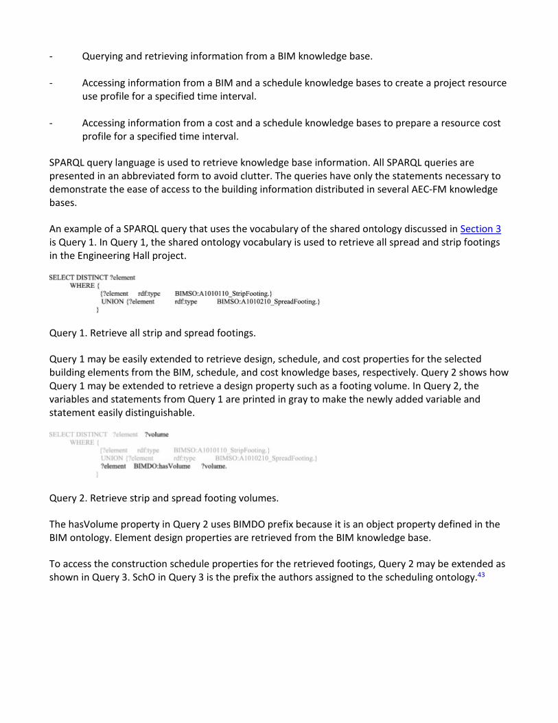
An example of a SPARQL query that uses the vocabulary of the shared ontology discussed in Section 3 is Query 1. In Query 1, the shared ontology vocabulary is used to retrieve all spread and strip footings in the Engineering Hall project.
Query 1. Retrieve all strip and spread footings.
Query 1 may be easily extended to retrieve design, schedule, and cost properties for the selected building elements from the BIM, schedule, and cost knowledge bases, respectively. Query 2 shows how Query 1 may be extended to retrieve a design property such as a footing volume. In Query 2, the variables and statements from Query 1 are printed in gray to make the newly added variable and statement easily distinguishable.
Query 2. Retrieve strip and spread footing volumes.
The hasVolume property in Query 2 uses BIMDO prefix because it is an object property defined in the BIM ontology. Element design properties are retrieved from the BIM knowledge base.
To access the construction schedule properties for the retrieved footings, Query 2 may be extended as shown in Query 3. SchO in Query 3 is the prefix the authors assigned to the scheduling ontology.43

Query 3. Retrieve design and schedule properties.
Query 3 demonstrates the ease of access to element properties from two knowledge bases using the shared ontology vocabulary to identify building elements. Query 3 identifies the activities that contain the footing elements selected, retrieves activities' early start and early finish times, and filters out activities that their early finish times are not in April 2016.
The volume of a footing represents the amount of concrete needed for building the footing; hence, the volumes retrieved from Query 2 represent the amounts of concrete needed for pouring the Engineering Hall footings. Since footing construction were the only concrete pouring activities for the Engineering Hall project in April 2016, the results from Query 3 represent the concrete use profile for Engineering Hall during April 2016. Query 3 may be used to automate the preparation of purchase orders for project resources.
Query 4 is designed to retrieve schedule and cost information for footing construction activities that finish in April 2016. mueo is the prefix that the authors assigned to the cost estimating ontology.32,42
Query 4. Retrieve schedule and cost properties
The cost and schedule information retrieved from query 4 may be used to prepare a construction cost profile for Engineering Hall for April 2016. In Query 4, the last four statements find the assembly that estimates a footing element and retrieve the assembly's cost value. Cost is a compound value type and requires a value and a unit in order to be fully defined. The same is true for footing volume in Query 2. However, for the sake of brevity the statements that define units are not printed. More detailed discussion of a semantics based estimating method is presented in.32 Prefixes BIMSO and BIMDO used in this paper have replaced the muso and mudo prefixes used in.32

The results from a number of SPARQL queries for inter-domain information access were compared to similar information that were manually extracted from design, schedule, and cost documents of Engineering Hall; no discrepancies were observed. The approach presented in this paper is obviously a lot faster than manual methods for information access and has the potential to substantially increase productivity in the construction industry.
Queries 1 to 4 clearly demonstrate the role of shared ontology as a query mediator. The fact that all building domain ontologies are derived from a shared ontology enables all building domain knowledge bases to understand queries composed of the shared ontology vocabulary.
Summary and conclusion
Architecture, engineering, construction, and facility management (AEC-FM) industry involves collaboration among several experts in different domains. Successful completion of an AEC-FM project requires continuous exchange of information among project participants and addition of new information to a project's BIM knowledge base. To improve the accuracy and the efficiency of information exchange among various construction domains, it is necessary to store information once where it is generated and allow access to the information over the Internet. It is also desirable to store project data in a format that allows machine processing of routine operations. The Semantic Web technology uses a graph data structure for information modeling which facilitates integrating information from different sources and allows computers to access and process information distributed over the Internet.
The Semantic Web uses ontologies to define the organization of data. ifcOWL is an IFC-based ontology that consists of all concepts included in the IFC library. Extending a single ontology such as ifcOWL to include all concepts and relationships in all AEC-FM domains is not easy and may not even be practical. Instead of developing a single large ontology, independent domain ontologies may be developed and used for information sharing. However, such an approach would require mappings among all domain ontologies. Ontology mapping or alignment is the process of finding the correspondences between the concepts in two different domain ontologies. Mapping a large number of classes in several domains is a manual process and thus very time consuming and error prone. Instead of explicitly mapping domain ontologies to each other, a shared ontology approach may be used. A shared ontology approach identifies concepts common to various AEC-FM domains and uses the concepts for building the shared ontology. The shared ontology is used by all domains for creating domain specific ontologies and acts as a semantic mediator in the ontology alignment process.
Although an IFC-based modular ontology with a shared core and compatible domain models derived from the core could be conceived, in this study, the authors defined a BIM shared ontology referred to as BIMSO that includes all elements in the UNIFORMAT II classification system. The study also presented a building design ontology referred to as BIMDO that extends BIMSO and defines design properties for building elements. BIMSO and BIMDO ontologies were used to create a BIM knowledge base for a 3-storey building project. The BIM knowledge base along with a schedule and a cost knowledge bases were used to demonstrate the effectiveness of the shared ontology approach in enabling a single search interface across the AEC-FM domains. Two scenarios were investigated: (1) retrieve information from a design and a schedule knowledge bases for creating a resource use profile for a project, and (2) retrieve information from a schedule and a cost knowledge bases for creating a
resource cost profile. The queries used in both scenarios clearly demonstrated the effectiveness of the shared ontology as a query mediator. The fact that all building domain ontologies were derived from a shared ontology enabled the three building domain knowledge bases to understand queries composed of the shared ontology vocabulary and return the domain-specific element properties demanded.
References 1 P. Pauwels, R. De Meyer, J. Van Campenhout. “Interoperability for the design and construction
industry through semantic web technology.” Semantic Multimedia, Springer (2011), pp. 143-158.
2 C. Eastman, Y. Jeong, R. Sacks, I. Kaner. “Exchange model and exchange object concepts for
implementation of national BIM standards.”.J. Comput. Civ. Eng., 24 (2009), pp. 25-34. 3 T. Kang, H. Choi. “BIM perspective definition metadata for interworking facility management data.”
Adv. Eng. Inform. (2015), pp. 958-970. 4 D. Allemang, J. Hendler. “Semantic Web for the Working Ontologist: Effective Modeling in RDFS and
OWL.” Morgan Kaufmann (2011). 5 W.J. O'Brien, C.T. Formoso, V. Ruben, K London. Construction Supply Chain Management Handbook.
CRC press (2008). 6 H Knublauch, D Oberle, P Tetlow, E Wallace. A Semantic Web Primer for Object-Oriented Software
Developers. <http://www.w3.org/TR/sw-oosd-primer/>, 2015 (2006).
7 Extensible Markup Language (XML) <http://www.w3.org/XML/>, 2016 (2015).
8 Introduction to: RDF vs XML <http://www.dataversity.net/introduction-to-rdf-vs-xml>, 2016 (2012).
9 W3C SEMANTIC WEB <https://www.w3.org/2001/sw/>, 2016 (2013).
10 W3C RDF Working Group, Resource Description Framework (RDF) <http://www.w3.org/RDF/>, 2015 (2014).
11 M. Niknam, S. Karshenas. “Sustainable design of buildings using semantic BIM and semantic web services.” Wai Oswald Chong, Jae Chang, Kristen Parrish (Eds.), Procedia Engineering. Chicago, IL, May 10-13, 2015, 118 (2015), pp. 909-917, 10.1016/j.proeng.2015.08.530.
12 M. Niknam, S. Karshenas. “A social networking website for AEC projects.” Raymond Issa, Ian Flood
(Eds.), Computing in Civil and Building Engineering (2014). Orlando, FL, June 23–25, 2014 (2014), pp. 2208-2215, 10.1061/9780784413616.274.
13 W3C Standard, Ontologies <http://www.w3.org/standards/semanticweb/ontology>, 2015 (2015).
14 T.R. Gruber. “A translation approach to portable ontology specifications.” Knowl. Acquis., 5 (1993), pp. 199-220.

15 N.F. Noy, D.L. McGuinness. Ontology Development 101: A Guide to Creating your First Ontology. (2001).
16 G. Antoniou, F. Van Harmelen. A Semantic Web Primer. MIT press (2004). 17 S. Karshenas, M. Niknam. “Ontology-based building information modeling.” Ioannis Brilakis,
SangHyun Lee, Burcin Becerik-Gerber (Eds.), Computing in Civil Engineering (2013). Los Angeles, California, June 23–25, 2013 (2013), pp. 476-483, 10.1061/9780784413029.060.
18 J. Beetz, J. Van Leeuwen, B. De Vries. “IfcOWL: a case of transforming EXPRESS schemas into
ontologies.” Artif. Intell. Eng. Des. Anal. Manuf., 23 (2009), pp. 89-101. 19 BuildingSMART: Linked Data Working Group <http://www.buildingsmart-tech.org/future/linked-
data>, 2016. 20 BuildingSMART Proposed Recommendation: EXPRESS-to-OWL conversion routine
<http://www.buildingsmart-tech.org/future/linked-data/ifcowl/express-to-owl-conversion-procedure-proposed-recommendation>, 2016 (2015).
21 3rd International Workshop on Linked Data in Architecture and Construction (LDAC) <http://ldac-
2015.bwk.tue.nl/LDAC_2015_workshopreport.pdf>, 2016 (2015). 22 P. Pauwels, W. Terkaj. “EXPRESS to OWL for construction industry: towards a recommendable and
usable ifcOWL ontology.” Autom. Constr., 63 (2016), pp. 100-133. 23 T. Segaran, C. Evans, J. Taylor. Programming the Semantic Web, “O'Reilly Media, Inc.” (2009). 24 J. Hebeler, M. Fisher, R. Blace, A. Perez-Lopez. Semantic Web Programming. John Wiley & Sons
(2011). 25 M. Uschold, M. King. Towards a Methodology for Building Ontologies. Citeseer (1995). 26 T.R. Gruber. “Toward principles for the design of ontologies used for knowledge sharing?” Int. J.
Hum. Comput. Stud., 43 (1995), pp. 907-928. 27 M. Fernández-López, A. Gómez-Pérez, N. Juristo. “Methontology: from ontological art towards
ontological engineering.” Anonymous (Ed.), AAAI-97 Spring Symposium Series, Stanford University, EEUU (1997).
28 Y. Sure, S. Staab, R. Studer. “On-to-knowledge methodology (OTKM).” Handbook on Ontologies,
Springer (2004), pp. 117-132. 29 M.C. Suárez-Figueroa. “NeOn Methodology for building ontology networks: specification, scheduling
and reuse.” Dissertations in Artificial Intelligence, 338, IOS Press (2012).

30 M.C. Suárez-Figueroa, A. Gómez-Pérez, E. Motta, A. Gangemi. “Ontology Engineering in a Networked World.” Springer Science & Business Media (2012).
31 M.C. Suárez-Figueroa, R. García-Castro, B. Villazón-Terrazas, A. Gómez-Pérez. Essentials in Ontology
Engineering: Methodologies, Languages, and Tools. (2011). 32 M. Niknam, S. Karshenas. “Integrating distributed sources of information for construction cost
estimating using semantic web and semantic web service technologies.” Autom. Constr., 57 (2015), pp. 222-238.
33 R Hodgson, PJ Keller, J Hodges, J Spivak. QUDT–Quantities, Units, Dimensions and Data Types
Ontologies. 2013, http://qudt.org. (2011). 34 BauDataWeb, The European Building and Construction Materials Database for the Semantic Web
<http://semantic.eurobau.com/>, 2015 (2015). 35 ASTM standard, Standard Classification for Building Elements and Related Sitework-UNIFORMAT II
<http://www.astm.org/Standards/E1557.htm>, 2015 (2015). 36 OmniClass <http://www.omniclass.org/>, 2016 (2013). 37 W3C, Naming and Addressing: URIs, URLs <http://www.w3.org/Addressing/>, 2015 (2005). 38 Sesame <http://rdf4j.org/>, 2015 (2015). 39 Apache Jena, A Free and Open Source Java Framework for Building Semantic web and Linked Data
Applications, 2015 (2015). 40 Pellet <https://github.com/complexible/pellet>, 2015 (2014). 41 Autodesk, Revit Building design and construction software.
http://www.autodesk.com/products/revit-family/overview>, 2015 (2015). 42 M. Niknam, S. Karshenas. “A semantic web service approach to construction cost estimating.”
Ioannis Bilakis, SangHyun Lee, Burcin Gerber (Eds.), Computing in Civil Engineering (2013). Los Angeles, CA, June 23–25, 2013 (2013), pp. 484-491, 10.1061/9780784413029.
43 M. Niknam, S. Karshenas. “Integrating BIM and Project Schedule Information Using the Semantic
Web Technology.” José L. Perdomo-Rivera, Antonio Gonzáles-Quevedo, Carla López del Puerto, Francisco Maldonado-Fortunet, Omar I. Molina-Bas (Eds.), Proc., 2016 ASCE Construction Research Congress (CRC). San Juan, Puerto Rico, May 31–June 2, 2016 (2016), pp. 689-697, 10.1061/9780784479827.070.