A semi-analytical method for the post-local-torsional buckling analysis of prismatic plate...
13
INTERNATIONAL JOURNAL FOR NUMERICAL METHODS IN ENGINEERING, VOL. 18, 1685-1697 (1982) A SEMI-ANALYTICAL METHOD FOR THE POST-LOCAL-TORSIONAL BUCKLING ANALYSIS OF PRISMATIC PLATE STRUCTURES SRINIVASAN SRIDHARAN~ Department of Civil Engineering, Washington University, St. Louis, Missouri, U.S.A. INTRODUCTION In recent times, post-local-buckling behaviour of plate structures has received considerable attention. This is because of the need to estimate the often significant reserve strength and stiffness of locally buckled structures. The essential characteristic of local buckling is that the junctions do not participate in the buckling process and remain practically straight, while the individual plates develop out of plane deformation (Figure lb). In contrast to the purely local buckling, local-torsional and forms of overall buckling (Figure la) involve translations of I L I .... -_____-- Figure 1. (a) Examples of local-torsional and overall buckling; (b) examples of purely local buckling junctions in the cross-sectional plane with some of the members developing inplane deforma- tion. Although this type of buckling has been widely in~estigated,'-~ little information is available on the stiffness of the plate structures after such buckling has occurred. Experiments have been used almost exclusively to gain an insight into the phenomenon and formulate design recommendations for individual but no systematic theoretical analysis appears to have been attempted. t Assistant Professor 0029-5981/82/111685-13$01.30 @ 1982 by John Wiley & Sons, Ltd. Received October 1981 Revised December 1981
-
Upload
srinivasan-sridharan -
Category
Documents
-
view
220 -
download
0
Transcript of A semi-analytical method for the post-local-torsional buckling analysis of prismatic plate...

INTERNATIONAL JOURNAL FOR NUMERICAL METHODS IN ENGINEERING, VOL. 18, 1685-1697 (1982)
A SEMI-ANALYTICAL METHOD FOR THE POST-LOCAL-TORSIONAL BUCKLING ANALYSIS
OF PRISMATIC PLATE STRUCTURES
SRINIVASAN S R I D H A R A N ~
Department of Civil Engineering, Washington University, St. Louis, Missouri, U.S.A.
INTRODUCTION
In recent times, post-local-buckling behaviour of plate structures has received considerable attention. This is because of the need to estimate the often significant reserve strength and stiffness of locally buckled structures. The essential characteristic of local buckling is that the junctions do not participate in the buckling process and remain practically straight, while the individual plates develop out of plane deformation (Figure lb). In contrast to the purely local buckling, local-torsional and forms of overall buckling (Figure l a ) involve translations of
I L I .... -_____--
Figure 1. (a) Examples of local-torsional and overall buckling; (b) examples of purely local buckling
junctions in the cross-sectional plane with some of the members developing inplane deforma- tion. Although this type of buckling has been widely in~estigated, ' -~ little information is available on the stiffness of the plate structures after such buckling has occurred. Experiments have been used almost exclusively to gain an insight into the phenomenon and formulate design recommendations for individual but no systematic theoretical analysis appears to have been attempted.
t Assistant Professor
0029-5981/82/111685-13$01.30 @ 1982 by John Wiley & Sons, Ltd.
Received October 1981 Revised December 1981

1686 S . SRIDHARAN
A long prismatic plate structure under axial compression would buckle into several half - waves, so that some approximation of the end boundary conditions can often be accepted. It is therefore possible to represent the displacements in the longitudinal direction by their characteristic forms which satisfy the governing differential equations. This suggests the use of a semi-analytical approach with discretization in the transverse direction alone. Often called the finite strip technique, this method has been applied for the post-local-buckling analysis of thin-walled structures with very satisfactory result^:^-^ an order of magnitude reduction in the computing effort compared with the conventional finite element, rapid convergence of the solution and the exact satisfaction of the inplane equilibrium condition in the longitudinal direction. In this paper the finite strip method is extended to the problem of post-local-torsional and overall buckling in the sense defined earlier. As in the case of the purely local buckling,’ two modes of loading are considered-one of prescribed end displacements and the other of prescribed load eccentricity. The cases of uniform compression and pure bending may be thought of as the respective limiting cases of these modes of loading. Examples are presented to illustrate the convergence of the proposed method and to gain insights into the post-buckled responses of a few common plate structures. Since a perturbation technique is employed in the analysis, the validity of the results is restricted to the close vicinity of bifurcation.
THEORY
Derivation of the x-variation of displacements
The functions describing the displacements u, v and w in the longitudinal direction (Figure 2) are derived from the governing differential equations of the problem. The equations may be derived as Euler equations associated with the potential energy functional. If the end compression displacements are specified for the structure, the total potential energy reduces to the total internal strain energy. For a linearly elastic material, the strain energy stored per
J
/
/ / y,v
Figure 2. Finite strip configuration and the local co-ordinate system of a typical strip
BUCKLING ANALYSIS OF PRISMATIC PLATE STRUCTURES 1687
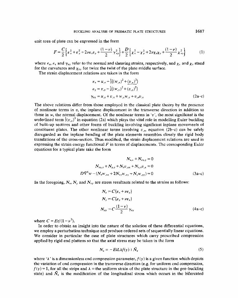
unit area of plate can be expressed in the form
where E,, E , and yxy refer to the normal and shearing strains, respectively, and xx and xy stand for the curvatures and xXy for twice the twist of the plate middle surface.
The strain displacement relations are taken in the form
The above relations differ from those employed in the classical plate theory by the presence of nonlinear terms in U, the inplane displacement in the transverse direction in addition to those in w, the normal displacement. Of the nonlinear terms in ‘U’, the most significant is the underlined term + ( u , ~ ) ’ in equation (2a) which plays the vital role in modelling Euler buckling of built-up sections and other forms of buckling involving significant inplane movements of constituent plates. The other nonlinear terms involving U , , , equation (2b-c) can be safely disregarded as the inplane bending of the plate elements resembles closely the rigid body translations of the cross-section. Thus modified, the strain displacement relations are used in expressing the strain energy functional F in terms of displacements. The corresponding Euler equations for a typical plate take the form
NX,, +Nxy,y = 0
NXy,, + Ny,y + N,u,,, + N,.,u,, = 0
D V 4 w - (NXw,,, + ~N,,w,,, + N , W , ~ , ) = 0
In the foregoing, N,, N y and Nxy are stress resultants related to the strains as follows:
N, = C{E, + my} N , = C { E ~ + vex}
(3 a-c)
(4a-c)
where C = Et/(l- v’). In order to obtain an insight into the nature of the solution of these differential equations,
we employ a perturbation technique and produce ordered sets of sequentially linear equations. We consider in particular the case of plate structures which carry prescribed compression applied by rigid end plattens so that the axial stress may be taken in the form
N, = -EtLAf(y)+Nx ( 5 )
where ‘ A ’ is a dimensionless end compression parameter, f ( y ) is a given function which depicts the variation of end compression in the transverse direction (e.g. for uniform end compression, f ( y ) = 1, for all the strips and A =the uniform strain of the plate structure in the pre-buckling state) and RX is the modification of the longitudinal stress which occurs in the bifurcated

1688 S . SRIDHARAN
equilibrium state. We therefore write
A = A " + A " ) S + A ' ~ ) S ~ + . . . N, = i q 1 ) S + N y + NL3's3 + . . . N , = N ~ ) s + N ~ ) s ~ + . . .
N,, = N"s + NK)s2 +. . . u = u n + u ~ 1 ~ s + u ~ 2 ~ s 2 + . . .
v = v o + v ( l ) s + v(2)s2 + . . . (6a-f)
where 's' is the perturbation parameter which varies continuously along the secondary path. It is convenient to view this as the amplitude of the buckling mode. The superscript 0 refers to the unbuckled configuration and the quantity U' arises as a consequence of Poisson expansion in the transverse direction in order that the plates may be in a state of uniaxial compression.
(1 ) (2) 2 w = w s + w s +...
The ordered sets of perturbation equations take the following forms;
(7a-c)
second-order equations
NL:; +No,y = o NL:!, +NE; -EtLf(y){hO~!?i +A(')V!~~}+RY'VY~ +N:~v!:' = 0
4 (2) 0 ( 2 ) ( 1 ) ( 1 ) - ( 1 ) ( 1 ) ( 1 ) (1 ) ( 1 ) (1) - DV w +EtLf(y)O w,,,+A W , ~ ~ I - ( N , w,, ,+2N,,w,, ,+NY w, , , ) -O @a-c)
third-order equations NE: +N:!y = 0
0 (3) ( 1 ) (2) (2) ( 1 ) NL;!, + N f t -EtLf(y ){A v ,xx + A z),,~ + A v,,,}
0 - (2) (1) - ( I ) (2) ( 1 ) - ( 1 ) (2) =
+ A (*)w!:i}
+ N x v , ~ , + N x v , , ~ +N,.,v., +N,.,v,,
- ( N , w,,, +2N,, w,,, + N , w , , ~ ) - ( N , w,,, +2N,, w,, , + N , w,, , ) = 0
DV4w'3' + EtLf(y){A 'ww:i + A ("w - ( 2 ) ( 1 ) (2) ( 1 ) (21 ( 1 ) - ( I ) ( 2 ) ( 1 ) (2) (1) ( 2 ) (9a-c)
Substituting for #;:i and N$,, in terms of u ( l ) and v ( ' ) , the first-order equations appear as uncoupled in w(l ) and u ( ~ ) , but because of the boundary conditions which require compatibility of deformation along the longitudinal edges, they are in fact coupled. The solutions for u( l ) , v( ' ) and w( ' ) take the form
mrrx U ( 1 ) = U : ' ( y ) cos ( T)
(1 Oa-c)

BUCKLING ANALYSIS OF PRISMATIC PLATE STRUCTURES 1689
In the foregoing, 'm' is the number of half-waves of buckling which is assumed to be even in subsequent discussion, and L is the total length of the plate structure.
Now expressing the first- and second-order stress resultants in terms of both the first- and second-order displacements and making use of equation (10a-c) the second set of equations take the form
2 2 -m IT m m 2mnx - L ( 1 - v 2 ) A ( ' ) f ( y ) U : ) ( ~ ) L2 sin (L) =F2(y)+F3(y)cos (7)
2 2 m ITX DV4w(')+ EtLA Of (y)w!:L + EtLA")f (y ) w :)( T) sin ( L) (1 la-c)
In the foregoing F,, . . . , F5 are appropriate functions of 'y'. The solution for U"), U") and w( ' ) take the form
(12a-c)
If 'm' is even, these functions are orthogonal to their respective first-order counterparts, a necessary requirement in the uniqueness of the asymptotic solution. This requirement also ensures that A''' = 0, which means that the bifurcation is symmetric. It is not proposed to consider higher order equations since for an initial post-buckling analysis it is sufficient to solve the first- and second-order equations.
Displacement functions for the transverse direction
Equations (10a-c) and (12a-c) give the variation of the displacements in the longitudinal direction. Each of the functions of y appearing in the description of inplane displacements are taken to be linear, whereas cubic functions associated with 4 degrees-of-freedom are employed in the description of normal displacements.
Loading and end boundary conditions
Figure 3 shows the variation of displacements in the cross-sectional plane ( w-U) along the length of the structure. The structure may be thought of as being compressed by rigid plattens along the planes of symmetry AA and BB (Figure 3a). At these planes the section is free to distort but no rotations relative to the plattens are allowed to occur; also the shear stresses at these cross-sections vanish. Thus the analysis treats of a case in which the plattens are

1690 S . SRIDHARAN
I
( a ) Initial buckling mode
Dtsplocement of a
pcrticipating in local torsional or overall buckling
t
Inplone buckling of a stlffener and a possible loading arrangement
Figure 3. Idealization of the end boundary conditions
completely frictionless (Figure 3b). The case of prescribed load eccentricity is modelled by allowing the plattens to rotate by an appropriate amount in the post-buckling range, as there occurs a redistribution of longitudinal stresses over the section.
Equilibrium equations in terms of nodal degrees-of-freedom
form The total potential energy of a typical plate strip under prescribed end shortening takes the
Ustw = [a,, - (W + A *cl,)Iqlq, + [cf lp - ~d,, lr ,r , + a,,,r,q,q, + al,k~qlq,qkqf
i , j , k , l = l , . . . , 8 n , p = l , ..., 14 (13)
In the foregoing, q’s and r’s stand for the local degrees-of-freedom of the strip which are the amplitudes of displacements and rotation along the strip edges for the first- and second-order displacement fields, respectively. a,, . . . aIlkl are coefficients which are obtained by integration along x and y directions. An explicit expression for the energy function is given in Reference 12. Note in particular that the cubic terms in q’s are absent because of the assumption of even number of half-waves of buckling. The higher order terms in r’s either vanish or are of no interest in view of the limited scope of the analysis. A* is a parameter which controls the modification of the end displacement pattern, necessary to model the case of prescribed load eccentricity. When multiplied by a linear function f*(y ) for a typical strip it prescribes a rotation

BUCKLING ANALYSIS OF PRISMATIC PLATE STRUCTURES 1691
or translation of the end platterns. Since A * = 0 in the unbuckled configuration, we have
A * = A : S + A ; S ~ + . . . (14)
By a process of transformation of the expression for Ustrip (equation 13) and summation over the strips, the total strain energy of the structure can be expressed in terms of the global degrees-of-freedom as follows:
(15)
Here Q’s and R’s stand, respectively, for the global degrees-of-freedom corresponding to the first- and second-order quantities. The i, j , k, 1 and m, n range over the total numbers of the corresponding global degrees-of-freedom, M and N.
Ustrut = [Aij - (ABij + A * Cij)]QiQj + [ G p - ADnpIRnRp + AnijRnQiQj + AijkrQiQjQkQ,
In view of equations (6a) and (14), the eigenvalue prbblem may be stated as
(A, - A O B ~ ~ ) Q ~ = o 0‘ = 1 , . . . , M ) i = I , . . . , M (16) The second-order system of equations take the form
[C,,-AOD,,]R,+~A,~jQiQj=O { i , j = l , . . . , M } (p= 1 , . . . , N } n = 1,. . . , N (17)
The solutions of these equations may be expressed in the form
Qi = Qll’s (i = 1, . . . , M )
R, = R?)S* (n = I , . . . , N ) (1 8a-b)
It is now possible to evaluate A T and A; by requiring the total moment of the axial stresses at the end section about the point of application of the load to vanish. For cases in which the plattens are constrained to rotate about a given pivot, A T = A; = 0.
The total potential energy can now be expressed as a function ‘s’, the perturbation parameter: (1) (1) 2 (2) (2) 4 Ustrut={A,/-(AB,/+A*Cl/)}Q, Q, s +{Cnp-ADnp}Rn Rp s
(19) (1) (1) (1) (1) 4 +Anl,R~2)Q11)Qj1)~4+AIlkiQ, Q, Q k Q r s
In order that this function be stationary with respect to s, (1) (1) { A , - (AB,, + A *C,,)}Q, Q, + 2[{Cnp - hDnp}R ‘,2’R Z’S’
(20) ( 2 ) (1 ) ( 1 ) (1) (1) (1) ( 1 ) 2 +A,,$, Q, Q, +AlrkiQt Q, Q k Q r IS = o From equation (16),
From equation (17),
(22) With the aid of equations (18), (19), (6a) and (14), it is possible to extract the values of A “ ’
{C,,-AoD,,}Rn ( 2 ) R , ( 2 ) +:An,R‘,2’Q~”Qj1’ = O
and A(’) from equation (20) in the forms
1692 S . SRIDHARAN
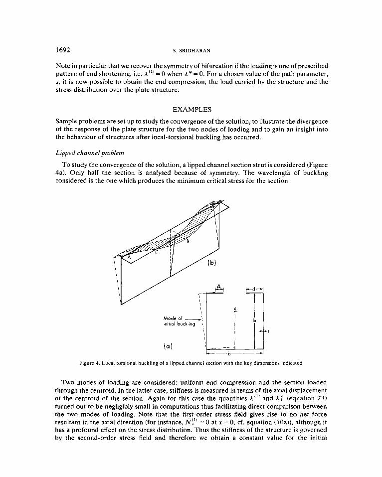
Note in particular that we recover the symmetry of bifurcation if the loading is one of prescribed pattern of end shortening, i.e. A"' = 0 when A * = 0. For a chosen value of the path parameter, s, it is now possible to obtain the end compression, the load carried by the structure and the stress distribution over the plate structure.
EXAMPLES
Sample problems are set up to study the convergence of the solution, to illustrate the divergence of the response of the plate structure for the two nodes of loading and to gain an insight into the behaviour of structures after local-torsional buckling has occurred.
Lipped channel problem
To study the convergence of the solution, a lipped channel section strut is considered (Figure 4a). Only half the section is analysed because of symmetry. The wavelength of buckling considered is the one which produces the minimum critical stress for the section.
t
Mode of --I initial buckling 'i,
t
&-b---&
Figure 4. Local torsional buckling of a lipped channel section with the key dimensions indicated
Two modes of loading are considered: uniform end compression and the section loaded through the centroid. In the latter case, stiffness is measured in terms of the axial displacement of the centroid of the section. Again for this case the quantities A"' and A T (equation 23) turned out to be negligibly small in computations thus facilitating direct comparison between the two modes of loading. Note that the first-order stress field gives rise to no net force resultant in the axial direction (for instance, = 0 at x = 0, cf. equation (lOa)), although it has a profound effect on the stress distribution. Thus the stiffness of the structure is governed by the second-order stress field and therefore we obtain a constant value for the initial

BUCKLING ANALYSIS OF PRISMATIC PLATE STRUCTURES 1693
I I 1
24 36 48 6A015 NUMBER OF STRIPS
Figure 5 . Convergence study on a lipped square channel section strut with h / r = 100, d/ r = 5 , I / ! = 425
post-buckling stiffness as in the purely local buckling problem. Figure 5 shows a plot of the values of 9, the ratio of post-buckling to pre-buckling stiffness obtained using an increasing number of strips in the analysis. It is seen that the solution converges rapidly in both the cases.
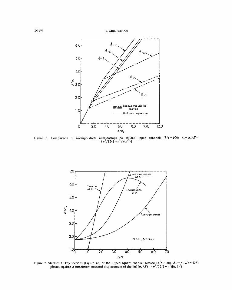
Figure 6 shows the average normalized stress-strain relations of channel sections with d/f = 3,5 and 10, for both the cases of loading. The post-buckling stiffness of the structure is seen to be significantly lower for the case of loading through the centroid.
Figure 7 shows the variations of the following key stresses with the maximum outward movement of the lip (A) for the channel section under uniform compression:
1. 2. 3.
4.
The average stress carried by the plate. The compressive stress at A, the tip of the lip at a plane of symmetry (Figure 4b). The tensile stress at B, the tip of the lip at a plane of symmetry, a half-wavelength away from A. The maximum compressive stress at the nodal section of the buckling mode which again occurs at the tip of the lip, C .
The compressive stress at 'A' builds up at the most rapid rate for small values of A/? but reaches a maximum whereafter it begins to diminish. The rapid build-up in the immediate vicinity of bifurcation is the result of inplane bending associated with the eigenmode. The reduction in the rate of increase in the stress with increasing A is the consequence of the redistribution of stresses in the post-buckling range, as given by the second-order inplane stress system which throws the least compressive stress (or tension) on regions with the largest buckling deformation. In practical steel structures, plastic yielding will set in well before this moderating effect is realized to any significant extent. Depending upon the ratio of uy/uo, this yielding at the tip of the stiffner may occur either in tension or compression. If compressive yield occurs, then localized collapse by plastic buckling, such as observed in experiments,'".' ' is the most likely consequence. It is possible to read out, from Figure 7, the average stress corresponding to the first yield for a given u+,/ao.
1694 S. SRIDHARAN
.o E /E,
Figure 6. Comparison of average-stress relationships on s uare lipped channels [b/f = 100; F" = U& = qz {m-2/12(1 - U Z ) ( f / b ) 11
0
Figure 7. Stresses at key sections (Figure 4b) of the lipped square channel section (b/f = 100, d / t = 5, I / r = 425) plotted against A (maximum outward displacement of the lip) (uo /E) = {.n2/12(1 - u*)]{ t /b} ' )

BUCKLING ANALYSIS OF PRISMATIC PLATE STRUCTURES 1695
Stiffened plate under pure bending
Figure 8(a) shows a simply-supported plate carrying a single stiffener subjected to pure bending. The buckling mode corresponding to the lowest critical moment is illustrated in Figure 8(b) and is seen to be an ‘overall’ mode. From the moment curvature relationship (Figure 8c), it is seen that the plate has significant elastic post-buckling stiffness; however, the compressive stress at the tip of the stiffener builds up at a rapid rate and overtakes the compressive stress at the edge of the plate immediately after buckling occurs. Thus once again the compressive stress at the tip of the stiffener caused by inplane bending sets a limit to the moment
=C m I / I ( 7 . 1 . 6 5 8 x 10³)
Figure 8. Bending moment, maximum stiffener stress and the maximum plate edge stress against the curvature ,y
CONCLUSIONS
A semi-analytical method is presented for the study of post-buckling behaviour of plate structures which buckle in modes that involve significant inplane movement of one or more of the plate elements. The influence of the mode of loading which may either be one of prescribed end compression or load eccentricity is discussed. Examples illustrate that one likely consequence of buckling of an edge stiffener in its own plane would be the onset of plastic yielding; and the yielding of a member which has been the main source of stiffness cannot but hasten the collapse of the structure.
APPENDIX I
C = Extensional rigidity = Et/ l - v’). A,, A,,,, A i i k l , C,,, D,, = Coefficients in the energy function.

1696 S . SRIDHARAN
D = Flexural rigidity=Et3/[12(1 - v’)]. E = Young’s modulus. L = Length of the structure.
M = Bending moment carried by the plate structure. M,, = Critical value of M.
N,, N,, Nxy = Membrane stress resultants. Qi = Global degrees-of -freedom corresponding to the first-order
R, = Global degrees-of-freedom corresponding to the second- displacement field.
order displacement field. b =Width of lipped square channel section. d = Depth of lip. I = Half-wavelength of buckling of plate structure = (L /m) . t = Thickness of plate strip.
m = Number of half-waves of buckling. A = Inplane outward movement of the lip of the channel section.
E,, E,, ’yxy = Normal and shearing strain components. x = Curvature of the centroidal line of the plate structure in the
plane of the applied bending moment. xc, = Critical value of x.
xx, xy and xrY = Curvature (a2w/aX2, a2w/a,2) and twist (2 a2w/ax a y ) of the
$=The ratio of the stiffness of the buckled to that of the
U =The average stress carried by the plate structure. uo = Critical stress parameter defined by {E7r2/12(1 - v2)}(t /b)’ . u, = Yield stress of the material.
deformed plate surface.
unbuckled structure.
v = Poisson’s ratio. A = A parameter defining average axial strain of the plate
A. = Critical value of A. A * = Axial strain parameter prescribed to vary with the buckling
deformation.
structure.
A comma denotes partial differentiation, e.g. U,, = au/ax.
REFERENCES
1 . W. H. Wittrick, ‘A unified approach to the initial buckling of stiffened panels in compression’, Aeronaut. Qly,
2. W. H. Wittrick and F. W. Williams, ‘Buckling and vibration of anisotropic or isotropic plate assemblies under
3. Y. K. Cheung, Finite Strip Method in Structural Analysis, Pergamon Press, 1976. 4. T. P. Desmond, T. Pekoz and G. Winter, ‘Intermediate stiffeners for thin-walled members’, J. Struct. Dio., ASCE,
5 . T. P. Desmond, T. Pekoz and G. Winter, ‘Edge stiffeners for thin-walled members’, J. Struc?. Dio., ASCE, 16056,
6. S. Sridharan, ‘Elastic postbuckling behavior and crinkly collapse of plate structures’, Ph.D. thesis, Univ. of
7. T. R. Graves Smith and S. Sridharan, ‘A finite strip method for the post-locally-buckled analysis of plate
XIX, 265-283 (1968).
combined loadings’, Znt. J. Mech. Sci., 16, 209-229 (1974).
16194, ST4,627-648 (1981).
ST2, 329-353 (19%~) .
Southampton (1978).
structures’, Znf. J. Mech. Sci., 20, 833-843 (1978).
BUCKLING ANALYSIS OF PRISMATIC PLATE STRUCTURES 1697
8. S. Sridharan and T. R. Graves Smith, ‘Postbuckling analyses with finite strips’, J. Eng. Mech. Div., ASCE, EM5,
9. S. Sridharan, ‘A finite strip analysis of locally buckled plate structures subject to nonuniform compression’ (to
10. T. P. Desmond, ‘The behaviour and strength of thin-walled compression elements with longitudinal stiffeners’,
11. A. C. Walker and S. Sridharan, ‘Analysis of the behaviour of axially compressed stringer-stiffened cylindrical
12. S. Sridharan, ‘Behaviour of plate structures after local-torsional and overall buckling’, Dept. Report No. 59, Civil
869-888 (1981).
be published in Engineering Structures).
Report No. 369, Dept. of Structural Engineering, Cornell Univ., Ithaca, New York, 1978.
shells’, Proc. Znstn CivilEngrs (U.K.), pt 2,69,447-472 (1980).
Engineering, Washington Univ. in St. Louis.

![[N. S. Trahair]Flexural-Torsional Buckling of Strorg)](https://static.fdocuments.us/doc/165x107/55cf8e61550346703b919745/n-s-trahairflexural-torsional-buckling-of-strorg.jpg)