A Self-Reconfiguration Control Regarding Recovery Effect ...
5
A Self-Reconfiguration Control Regarding Recovery Effect to Improve the Discharge Efficiency in the Distributed Battery Energy Storage System* Yong-Yong Cai 1 , Zhiliang Zhang 1 , Senior Member, IEEE, Yue Zhang 2 and Yan-Fei Liu 3 , Fellow IEEE 1 Jiangsu Key Laboratory of New Energy Generation and Power Conversion Nanjing University of Aeronautics and Astronautics, Nanjing, Jiangsu, P.R.China 2 Jiangsu Electric Power Company Nanjing Power Supply Company 3 Department of Electrical and Computer Engineering Queen’s University, Kingston, Ontario, Canada, K7L 3N6 [email protected], [email protected], [email protected] and [email protected] Abstract—The battery energy storage system in the MicroGrid tends to be distributed in the future, to solve the voltage sharing and overcharge/overdischarge problem, achieve high compatibility and reliability, etc. Based on the distributed architecture, this paper proposes a self-reconfiguration discharge strategy regarding the battery recovery effect to further enhance the battery performance and discharge efficiency of the battery energy storage system. The specific control strategy and principle analysis is presented in details, and the experimental result has verified the proposed concept. Index Terms: battery management system (BMS), energy storage, battery recovery effect, self-reconfiguration. I. INTRODUCTION The MicroGrid has two main forms, AC MicroGrid (ACMG) and DC MicroGrid (DCMG) [1]-[2]. Fig.1 shows a MicroGrid in a future home based on a DC bus. The DC bus is connected to the source as well as the load. The energy storage system is of great importance in the MicroGrid. It not only guarantees the stability, but also increases the power efficiency of the system [3]-[4]. The energy storage devices mainly include the battery, the super capacitor, the high-speed flywheel and the superconducting magnetic energy storage (SMES) etc [5]. The storage battery attains a promising application due to high power density, flexibility and so on. In order to solve the disadvantages existed in the centralized battery energy storage system (BESS), nowadays the BESS tends to be miniaturized and distributed [6]. A Micro-Bank Module (MBM), which consists of a micro- bidirectional DC/DC converter, a micro-BMS and a cell bank, is showed in Fig.2 (a). Several MBMs can be connected in parallel to increase the power level. Fig.2 (b) shows the distributed parallel architecture of the BESS. The benefits of the distributed architecture include 1) no voltage sharing problem and no overcharge/overdischarge problem; 2) high compatibility and reliability 3) high energy storage utilization; 4) better space utilization; 5) reduced volume and weight of the BMS. * A Project Funded by the Lite-On Fund, the NUAA Research Fund and the Priority Academic Program Development of Jiangsu Higher Education Institutions. In order to improve the energy storage utilization, this paper proposes a self-reconfiguration control strategy to improve the battery performance significantly taking advantage of the battery recovery effect. With the proposed control strategy, the capacity of each battery in the BESS can be fully utilized. Hence, high energy storage utilization can be achieved. DC DC Fuel Cell PV Array Wind Energy DC Bus Vbus 380 V (360~400 V) DC DC DC DC Energy Storage Load DC DC AC DC Fig.1 The Microgrid based on the DC bus (a) MBM (b) Distributed BESS in parallel Fig.2 Distributed BESS in parallel 978-1-4799-6735-3/15/$31.00 ©2015 IEEE 1774
Transcript of A Self-Reconfiguration Control Regarding Recovery Effect ...
A Self-Reconfiguration Control Regarding Recovery Effect to Improve the Discharge Efficiency in the
Distributed Battery Energy Storage System*
Yong-Yong Cai1, Zhiliang Zhang1, Senior Member, IEEE, Yue Zhang2 and Yan-Fei Liu3, Fellow IEEE 1Jiangsu Key Laboratory of New Energy Generation and Power Conversion
Nanjing University of Aeronautics and Astronautics, Nanjing, Jiangsu, P.R.China 2Jiangsu Electric Power Company Nanjing Power Supply Company
3Department of Electrical and Computer Engineering Queen’s University, Kingston, Ontario, Canada, K7L 3N6
[email protected], [email protected], [email protected] and [email protected]
Abstract—The battery energy storage system in the MicroGrid tends to be distributed in the future, to solve the voltage sharing and overcharge/overdischarge problem, achieve high compatibility and reliability, etc. Based on the distributed architecture, this paper proposes a self-reconfiguration discharge strategy regarding the battery recovery effect to further enhance the battery performance and discharge efficiency of the battery energy storage system. The specific control strategy and principle analysis is presented in details, and the experimental result has verified the proposed concept. Index Terms: battery management system (BMS), energy storage, battery recovery effect, self-reconfiguration.
I. INTRODUCTION The MicroGrid has two main forms, AC MicroGrid
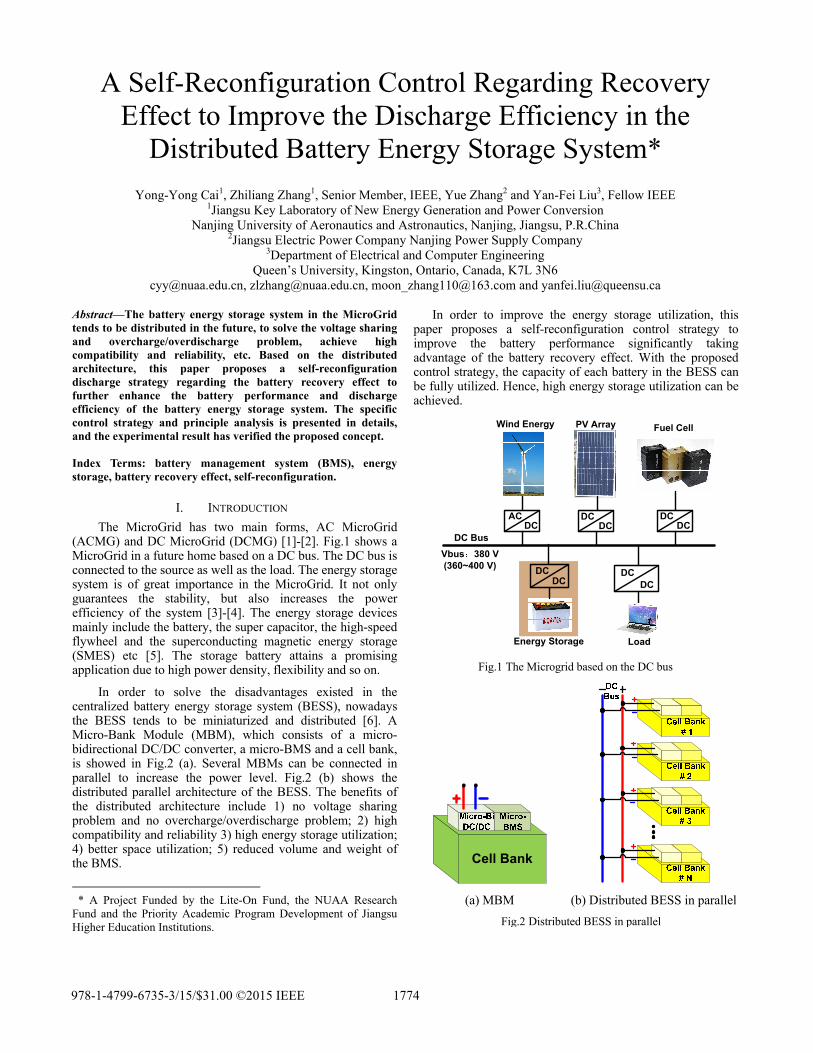
(ACMG) and DC MicroGrid (DCMG) [1]-[2]. Fig.1 shows a MicroGrid in a future home based on a DC bus. The DC bus is connected to the source as well as the load. The energy storage system is of great importance in the MicroGrid. It not only guarantees the stability, but also increases the power efficiency of the system [3]-[4]. The energy storage devices mainly include the battery, the super capacitor, the high-speed flywheel and the superconducting magnetic energy storage (SMES) etc [5]. The storage battery attains a promising application due to high power density, flexibility and so on.
In order to solve the disadvantages existed in the centralized battery energy storage system (BESS), nowadays the BESS tends to be miniaturized and distributed [6]. A Micro-Bank Module (MBM), which consists of a micro-bidirectional DC/DC converter, a micro-BMS and a cell bank, is showed in Fig.2 (a). Several MBMs can be connected in parallel to increase the power level. Fig.2 (b) shows the distributed parallel architecture of the BESS. The benefits of the distributed architecture include 1) no voltage sharing problem and no overcharge/overdischarge problem; 2) high compatibility and reliability 3) high energy storage utilization; 4) better space utilization; 5) reduced volume and weight of the BMS.
* A Project Funded by the Lite-On Fund, the NUAA Research
Fund and the Priority Academic Program Development of Jiangsu Higher Education Institutions.
In order to improve the energy storage utilization, this paper proposes a self-reconfiguration control strategy to improve the battery performance significantly taking advantage of the battery recovery effect. With the proposed control strategy, the capacity of each battery in the BESS can be fully utilized. Hence, high energy storage utilization can be achieved.
DCDC
Fuel CellPV ArrayWind Energy
DC BusVbus 380 V(360~400 V) DC
DCDC
DC
Energy Storage Load
DCDC
ACDC
Fig.1 The Microgrid based on the DC bus
(a) MBM (b) Distributed BESS in parallel Fig.2 Distributed BESS in parallel
978-1-4799-6735-3/15/$31.00 ©2015 IEEE 1774

II. PROPOSED SELF-RECONFIGURATION CONTROL BASED
ON BATTERY RECOVERY EFFECT
A. Battery Recovery Effect The Most commercial batteries are governed by the
complex non-linear internal chemical reactions to provide energy [7]-[8]. It is interesting to note that when the battery idles during some period without discharging, the diffusion process compensates for the depletion of the active materials during discharge and battery output voltage increases [9]-[10]. That is the non-linear discharge characteristic obtained by most batteries——the recovery effect, that is, the deliverable energy in a battery can be self-replenished, if left idling for sufficient time.
B. Proposed Self-Reconfiguration Control Strategy The battery recovery effect opens up the possibility of
the battery scheduling in the multiple-battery systems. The main idea here is to use multiple batteries in an interleaved fashion to prolong the combined battery life. In the proposed architecture, the battery banks are controlled by the local Micro DC/DC converters independently. So the self-reconfiguration strategy, which is to reconfigure the composite structure of multiple cell banks automatically according to the dynamic load/storage demand [11]-[12], is proposed to increase the energy utilization of the storage system.
Fig.3 shows the block diagram of the proposed control. Based on the information of the battery bank, etc. the voltage, current, the Micro-BMS can estimate the SOC of each battery bank from (1):
0 0
1 t
tN
SOC SOC i dC
(1)
where SOC0 is the initial SOC and is determined by the open circuit voltage of the battery bank, i(τ) is the discharge current and CN is the rated capacity.
Fig.3 Block diagram of proposed self-reconfiguration control
Seen from Fig.4, with the optimal scheduling algorithm of the self-reconfiguration discharge strategy, the SOC of each battery bank is calculated real time. Then, the SOC
information of each bank is shared by the Micro-BMS. The obtained PWM control signals communicate between the local Micro-BMS and DC/DC converter. The optimal scheduling algorithm is shown in Fig.6. Initially, the range of the operation SOC is set. Firstly, the banks that meet the range of the operation SOC are determined and sorted in a descending order in terms of their average SOC. Then, the first ranking N banks are selected to discharge based on the load demand. This reconfiguration can be performed with a constant time interval T, for example, T=10 minutes. If the discharge current increases, the value of T reduces. With the proposed scheduling algorithm, the energy efficiency and the lifespan of the battery banks can be improved significantly.
Fig.4 Flow chat of proposed Algorithm
C. The stability analysis of the proposed system Basically, there are two types of converters in the
distributed power system (DPS), one controls the bus voltage and the other controls the bus current. Though each converter in the system is well designed based on the stand-alone operation with sufficient stability, the stability is still a big potential issue in the system level due to the complex interaction among the converters [13]. The popular stability analysis method in DC DPS is based on the impedance criteria from (2) [14]-[15]:
1_
_ _ _1 1_
( )( ) ( )
( )
m nv bus
m system v busj i busjj ki bus
Z sT Z s Z s
Z s
(2)
_ ( )v busZ s is the sum of bus port impedence of the converter which controls the bus voltage, and _ ( )i busZ s is the sum of bus port impedence of the converter which controls the bus current. _m systemT is the equivalent loop gain of the system, if _m systemT meets the Nyquist criteria, the system is stable. In order to simplify this question, the electronic load is implemented in the propoesd system in this paper and set to the constant voltage mode to model a voltage sourve which can control the bus voltage, and the DC/DC converters are controled with sigle current loop to control the bus current. The output impedence of the ideal constant voltage source is zero. So the _ ( )v busZ s in this system is approximately zero, and the _m systemT can always meet the Nyquist criteria. So the testing system in this paper ensures the stability.
1775

III. EXPERIMENTAL RESULTS AND DISCUSSIONS In order to verify the proposed self-reconfiguration
control, the hardware platform has been built. Fig.5 shows the photo of the hardware platform. The system consists of four MBMs, which can provide a maximum power of 500 W respectively. With the proposed control, three MBMs are always active while one is idling. The system can provide a maximum power of 1500 W. The lithium battery module of 12 V/ 100 Ah from Pylon Technologies is chosen as the battery bank, and four battery banks are utilized.
The photo of prototype of 500 W MBM is illustrated in Fig.6. The ZVS Dual Active Bridge (DAB) converter is used as the Micro-Bi DC-DC converter. The Freescale DSP MC56F8257 is used as the Micro-BMS to implement the proposed control strategy. The specifications are as follows: battery voltage: Vbat=10.8~13.8 V; bus voltage: Vbus=360~400 V; output power: Po=500 W; switching frequency: fs=250~500 kHz. The component of the power train are as follows: the transformer turns ratio: n=1:16; total inductance Lr=30 μH; LV side MOSFETs Q1~Q4: BSC014N03LS (30 V/100 A/1.4 mΩ from Infineon); HV side MOSFETs Q5~Q8: IPP65R380E6 (650 V/ 10.6 A/ 0.38 Ω from Infineon). A hall-effect sensor BJHCS-PS25 is used to sample the LV side current and a hall-effect-based linear current sensor IC ACS712ELCTR-05B-T is used to sense the HV side current. Two isolation amplifiers HCPL-7840 are used to sample the LV and HV side voltage respectively.
Fig.5 Photo of experimental testing platform
Fig.6 Photo of prototype: DAB
A. The same idling time with the different power level In the test, the distributed BESS consists of four MBMs.
With the proposed self-reconfiguration control strategy, three MBMs are active to provide the output power while one stands by. In order to verify the proposed control strategy in a wide load range, the power level of the BESS is set to be 750W, 900W, 1200W and 1500W, corresponding to half load, 60% load, 80% load and full load of each active MBM in the system with the proposed control. The idling time is 15min.
Fig.7 (a) shows the discharge curves of the MBM with and without the proposed self-reconfiguration control in the distributed BESS with a power level of 1200W. In the distributed BESS with the conventional control, all of the four MBMs are active, and provide the power of 300W. So the discharge time of the system is determined by the MBM which reaches the voltage threshold first, as the red curve shown in Fig.7 (a). The left four curves represent the discharge curve of the four MBMs in the distributed BESS with the proposed self-reconfiguration control. While with the proposed control, three MBMs need to be active all the time, so the discharge time of the system is determined when two MBMs reach the threshold voltage. Then, the improved discharge time can be calculated. The idling time is for the battery to take the recovery process. It is observed that the voltage of the battery increases during the idling time, which demonstrates that the capacity of the battery can be increased owing to the battery recovery effect. As a result, the discharge time of the BESS is extended. Fig.7 (b) - Fig.7 (d) shows the similar situation with different power level of 750W, 900W and 1500W respectively.
11
11.5
12
12.5
13
13.5
0 20 40 60 80 100 120 140 160 180 200
系列1
系列2
系列3
系列4
系列5
(a) 1200 W
11
11.5
12
12.5
13
13.5
0 50 100 150 200 250 300 350
系列2
系列3
系列4
系列5
系列1
(b) 750 W
1776

11
11.5
12
12.5
13
13.5
0 50 100 150 200 250
系列1
系列2
系列3
系列4
系列5
(c) 900 W
11
11.5
12
12.5
13
13.5
0 20 40 60 80 100 120 140 160 180
系列2
系列3
系列4
系列5
系列
Discharge time(min)ts0 20 40 60 80 120 140 160 180100
11
11.5
12
12.5
13
13.5
Bat
tery
vol
tage
(V)
Bank1Bank2Bank3Bank4Bank*
Discharge time prolonged by 5.67%
(d) 1500 W Fig.7 Discharge curves of the MBM with different power level
Table I summarizes the measured discharge time of the BESS with and without the proposed self-reconfiguration control. The discharge time of the BESS is increased by 6.12%, 6.3%, 5.85% and 5.67%, corresponding to the power level of 750 W, 900 W, 1200 W and 1500 W. It is observed that the increased energy decreases slightly as the discharge current increases. So, it is concluded that the discharge current has limited influence on the effectiveness of the proposed control.
Table I Measured discharge time of the distributed BESS with the idling time of 15 min
Power level (W)
Conventional (min)
Proposed (min)
Improved efficiency
750 294 312 6.12% 900 238 253 6.3%
1200 179.5 190 5.85% 1500 141 149 5.67%
B. Different idling time with the same power level
In order to investigate the impact of different idling time on the effectiveness of the proposed self-reconfiguration control under the same power level, the idling time is set to be 5 min, 15 min and 30 min respectively. The power level of 750 W and 1500 W are chosen to make a sharp comparison. Fig.8-Fig.9 shows the discharge curve of the MBM under different discharge condition.
11
11.5
12
12.5
13
13.5
0 50 100 150 200 250 300 350
系列1
系列2
系列3
系列4
系列5
(a) 5 min
11
11.5
12
12.5
13
13.5
0 50 100 150 200 250 300 350
系列1
系列2
系列3
系列4
系列5
(b) 30 min Fig.8 Discharge curves with different idling time under the power
level of 750 W
11
11.5
12
12.5
13
13.5
0 20 40 60 80 100 120 140 160 180
系列1
系列2
系列3
系列4
系列5
(a) 5 min
11
11.5
12
12.5
13
13.5
0 20 40 60 80 100 120 140 160 180
系列1
系列2
系列3
系列4
系列5
Discharge time(min)ts0 20 40 60 80 120 140 160 180100
11
11.5
12
12.5
13
13.5
Bat
tery
vol
tage
(V)
Bank1Bank2Bank3Bank4Bank*
Discharge time prolonged by 3.2%
(b) 30 min Fig.9 Discharge curves with different idling time under the power
level of 1500 W
1777
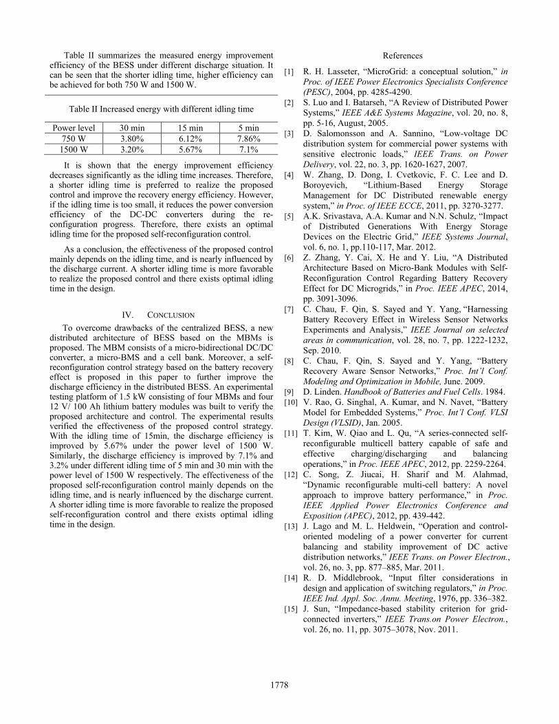
Table II summarizes the measured energy improvement efficiency of the BESS under different discharge situation. It can be seen that the shorter idling time, higher efficiency can be achieved for both 750 W and 1500 W.
Table II Increased energy with different idling time
Power level 30 min 15 min 5 min 750 W 3.80% 6.12% 7.86%
1500 W 3.20% 5.67% 7.1%
It is shown that the energy improvement efficiency decreases significantly as the idling time increases. Therefore, a shorter idling time is preferred to realize the proposed control and improve the recovery energy efficiency. However, if the idling time is too small, it reduces the power conversion efficiency of the DC-DC converters during the re-configuration progress. Therefore, there exists an optimal idling time for the proposed self-reconfiguration control.
As a conclusion, the effectiveness of the proposed control mainly depends on the idling time, and is nearly influenced by the discharge current. A shorter idling time is more favorable to realize the proposed control and there exists optimal idling time in the design.
IV. CONCLUSION To overcome drawbacks of the centralized BESS, a new
distributed architecture of BESS based on the MBMs is proposed. The MBM consists of a micro-bidirectional DC/DC converter, a micro-BMS and a cell bank. Moreover, a self-reconfiguration control strategy based on the battery recovery effect is proposed in this paper to further improve the discharge efficiency in the distributed BESS. An experimental testing platform of 1.5 kW consisting of four MBMs and four 12 V/ 100 Ah lithium battery modules was built to verify the proposed architecture and control. The experimental results verified the effectiveness of the proposed control strategy. With the idling time of 15min, the discharge efficiency is improved by 5.67% under the power level of 1500 W. Similarly, the discharge efficiency is improved by 7.1% and 3.2% under different idling time of 5 min and 30 min with the power level of 1500 W respectively. The effectiveness of the proposed self-reconfiguration control mainly depends on the idling time, and is nearly influenced by the discharge current. A shorter idling time is more favorable to realize the proposed self-reconfiguration control and there exists optimal idling time in the design.
References
[1] R. H. Lasseter, “MicroGrid: a conceptual solution,” in Proc. of IEEE Power Electronics Specialists Conference (PESC), 2004, pp. 4285-4290.
[2] S. Luo and I. Batarseh, “A Review of Distributed Power Systems,” IEEE A&E Systems Magazine, vol. 20, no. 8, pp. 5-16, August, 2005.
[3] D. Salomonsson and A. Sannino, “Low-voltage DC distribution system for commercial power systems with sensitive electronic loads,” IEEE Trans. on Power Delivery, vol. 22, no. 3, pp. 1620-1627, 2007.
[4] W. Zhang, D. Dong, I. Cvetkovic, F. C. Lee and D. Boroyevich, “Lithium-Based Energy Storage Management for DC Distributed renewable energy system,” in Proc. of IEEE ECCE, 2011, pp. 3270-3277.
[5] A.K. Srivastava, A.A. Kumar and N.N. Schulz, “Impact of Distributed Generations With Energy Storage Devices on the Electric Grid,” IEEE Systems Journal, vol. 6, no. 1, pp.110-117, Mar. 2012.
[6] Z. Zhang, Y. Cai, X. He and Y. Liu, “A Distributed Architecture Based on Micro-Bank Modules with Self-Reconfiguration Control Regarding Battery Recovery Effect for DC Microgrids,” in Proc. IEEE APEC, 2014, pp. 3091-3096.
[7] C. Chau, F. Qin, S. Sayed and Y. Yang, “Harnessing Battery Recovery Effect in Wireless Sensor Networks Experiments and Analysis,” IEEE Journal on selected areas in communication, vol. 28, no. 7, pp. 1222-1232, Sep. 2010.
[8] C. Chau, F. Qin, S. Sayed and Y. Yang, “Battery Recovery Aware Sensor Networks,” Proc. Int’l Conf. Modeling and Optimization in Mobile, June. 2009.
[9] D. Linden. Handbook of Batteries and Fuel Cells. 1984. [10] V. Rao, G. Singhal, A. Kumar, and N. Navet, “Battery
Model for Embedded Systems,” Proc. Int’l Conf. VLSI Design (VLSID), Jan. 2005.
[11] T. Kim, W. Qiao and L. Qu, “A series-connected self-reconfigurable multicell battery capable of safe and effective charging/discharging and balancing operations,” in Proc. IEEE APEC, 2012, pp. 2259-2264.
[12] C. Song, Z. Jiucai, H. Sharif and M. Alahmad, “Dynamic reconfigurable multi-cell battery: A novel approach to improve battery performance,” in Proc. IEEE Applied Power Electronics Conference and Exposition (APEC), 2012, pp. 439-442.
[13] J. Lago and M. L. Heldwein, “Operation and control-oriented modeling of a power converter for current balancing and stability improvement of DC active distribution networks,” IEEE Trans. on Power Electron., vol. 26, no. 3, pp. 877–885, Mar. 2011.
[14] R. D. Middlebrook, “Input filter considerations in design and application of switching regulators,” in Proc. IEEE Ind. Appl. Soc. Annu. Meeting, 1976, pp. 336–382.
[15] J. Sun, “Impedance-based stability criterion for grid-connected inverters,” IEEE Trans.on Power Electron., vol. 26, no. 11, pp. 3075–3078, Nov. 2011.
1778