A. Sadek 2 1 and Helmi Attia 1,2 - P · PDF fileA. Sadek 2, M. Meshreki 1 and Helmi Attia 1,2...
27
Wiener Produktionstechnik Kongress Vienna, May 7-8, 2014 A. Sadek 2 , M. Meshreki 1 and Helmi Attia 1,2 1 Aerospace Structures, Materials and Manufacturing, National Research Council of Canada (NRC) 2 Department of Mechanical Engineering, McGill University Montreal, Quebec, Canada Email: [email protected] / [email protected] McGill
Transcript of A. Sadek 2 1 and Helmi Attia 1,2 - P · PDF fileA. Sadek 2, M. Meshreki 1 and Helmi Attia 1,2...

Advanced Material Removal Program
Wiener Produktionstechnik KongressVienna, May 7-8, 2014
A. Sadek2, M. Meshreki1 and Helmi Attia1,2
1Aerospace Structures, Materials and Manufacturing, National Research Council of Canada (NRC)
2Department of Mechanical Engineering, McGill UniversityMontreal, Quebec, Canada
Email: [email protected] / [email protected]
McGill
Advanced Material Removal Program McGill
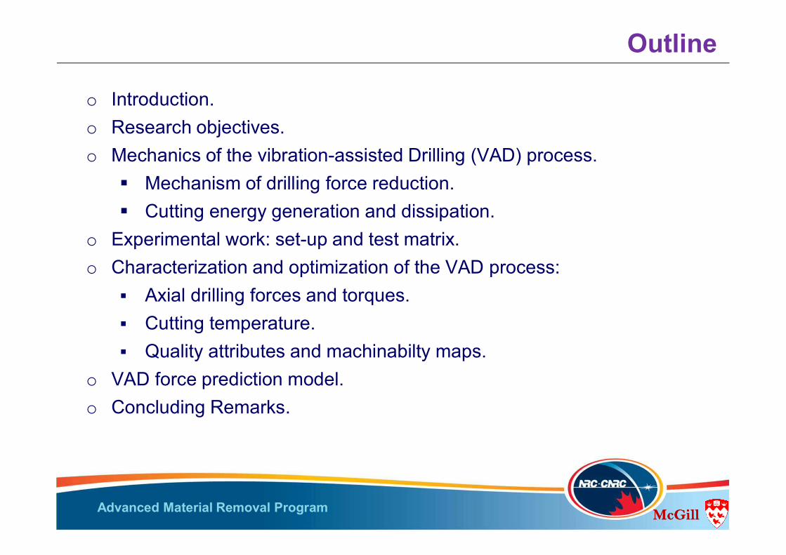
Outline
o Introduction.o Research objectives. o Mechanics of the vibration-assisted Drilling (VAD) process.
Mechanism of drilling force reduction. Cutting energy generation and dissipation.
o Experimental work: set-up and test matrix.o Characterization and optimization of the VAD process:
Axial drilling forces and torques. Cutting temperature. Quality attributes and machinabilty maps.
o VAD force prediction model.o Concluding Remarks.
McGill
Advanced Material Removal Program McGill
DelaminationMost Serious Damage Type
DelaminationMost Serious Damage Type
Thermal DamageMatrix Burnout
Thermal DamageMatrix Burnout
Low Productivity
Low Productivity
Poor Cutting(Fiber Fuzziness)
Poor Cutting(Fiber Fuzziness)
Tool rotate around its axis at an eccentric distance from the axis of the hole
Eliminate Dwell of Stationary Drilling
Tool Center
Eliminate Dwell of Stationary Drilling
Tool Center
Cyclic Engagement and Disengagement
of Tool
Cyclic Engagement and Disengagement
of Tool
Reduce Thrust Forces
Reduce Thrust Forces
Orbital DrillingOrbital Drilling
Vibration Assisted Drilling (VAD)
Vibration Assisted Drilling (VAD)
Superimposed axial vibratory motion over the conventional feed motion
Eliminate / minimize
Delamination
Eliminate / minimize
Delamination
Reduce Temperature
Reduce Temperature
Low ProductivityLow Productivity
Reduce axial Feed
Reduce axial Feed
Cutting/ Friction Temperature RiseCutting/ Friction Temperature Rise
Excessive Drilling Forces
Excessive Drilling Forces Intermittent
Cutting Techniques
Intermittent Cutting
Techniques Cooling EffectCooling Effect
Reduce Cutting Speed
Reduce Cutting Speed
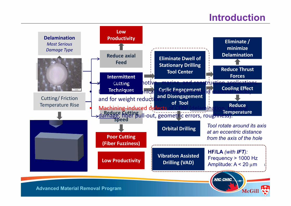
Introduction
• Aerospace, automotive, marine, and construction applications. • Drilling for mechanical fastening of of hybrid material stacks,
and for weight reduction.• Machining-induced defects of CFRP (delamination, thermal
damage, fiber pull-out, geometric errors, roughness).
LF/HA: Frequency < 100 HzAmplitude:25<A<800 mm
HF/LA (with IFT): Frequency > 1000 HzAmplitude: A < 20 mm

Advanced Material Removal Program McGill
Objectives
The main objectives of this investigation are: Analyzing the mechanics of force and temperature reduction
during the vibration assisted drilling (VAD) of FRPs. Developing machinability hole quality maps to characterize and
optimize the multi-dimensional VAD process parameters, for a given tool/workpiece materials.
Conceptual development of a VAD predictive force model that can deal with different process variables.

Advanced Material Removal Program McGill
P1: Max separation(initial axial step)
Feed
E2 E1
Tool-workpiece interaction
P3: Max separation
(new axial step)
p-p Amplitude
P2: Max engagement
DOC: Depth of Cut
E1 mean path
E2 mean path
Surface formed by E2
Surface formed by E1
Max DOCCylindrical Hole (Conventional)
Inst DOC d(t)
Min DOC
Hole opened (Vibrating Tool)
Surface formed by E2
Surface formed by E1
-0.07
-0.06
-0.05
-0.04
-0.03
-0.02
-0.01
0.00
0.01
0.02
-0.7
-0.6
-0.5
-0.4
-0.3
-0.2
-0.1
-1E-15
0.1
0.2
5 7 9 11 13 15
DO
C (m
m)
Posi
tion
(mm
)
Angular position (x π)
E2 E1 DOC
0.0
Engagement
Separation
Surface formed by E1
Surface formed by E2
DOC
Axi
al P
ositi
on (m
m)
Angular Position (x p)
DO
C (m
m)
P1 P3P2
Amplitude, Frequency ratio DOC Frequency Engagement period. (wm / wT) phase difference f.
-0.07
-0.06
-0.05
-0.04
-0.03
-0.02
-0.01
0.00
0.01
0.02
-0.7
-0.6
-0.5
-0.4
-0.3
-0.2
-0.1
-1E-15
0.1
0.2
5 7 9 11 13 15
DO
C (m
m)
Posi
tion
(mm
)
Angular position (x π)
E2 E1 DOC
0.0
Surface formed by E1
Surface formed by E2
DOC
Axi
al P
ositi
on (m
m)
Angular Position (x p)
DO
C (m
m)
P1 P3P2
Heat Generation
Heat Dissipation
Mechanics of VAD- Effect of A and wT

Advanced Material Removal Program McGill
-0.4
-0.2
0
0.2
0 5 10
Position(m
m)
Angularposition (xπ)
D2 D1 DOC
-0.4
-0.2
0
0.2
0 5 10
Position(m
m)
Angularposition (xπ)
D2 D1 DOC
-0.4
-0.2
0
0.2
0 5 10
Position(m
m)
Angularposition (xπ)
D2 D1 DOC
-0.4
-0.2
0
0.2
0 5 10
Position(mm)
Angularposition (xπ)
D2 D1 DOC
φ
Mechanics of VAD- Effect of A and wm
-0.4
-0.2
0
0.2
0 5 10
Position(m
m)
Angularposition (xπ)
D2 D1 DOC
-0.4
-0.2
0
0.2
0 5 10
Position(m
m)
Angularposition (xπ)
D2 D1 DOC
φ
Frequency A
mpl
itude
Formed chip profile
φ
DOC
Engagement Period (t) As Frequency
Phase shift “φ”Period (t) DOC
D Frequency Phase shift “φ” Period (t) DOC
Advanced Material Removal Program McGill
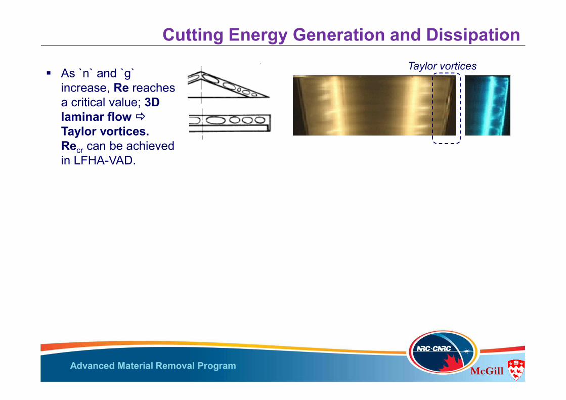
Cutting Energy Generation and Dissipation w
As `n` and `g` increase, Re reaches a critical value; 3Dlaminar flow Taylor vortices.Recr can be achieved in LFHA-VAD.
Conical gaps formed by the drill (2q ~ 120o) has the same flow pattern as that between flat discs.
Taylor vortices

Advanced Material Removal Program McGill
Re, n
0 50 100 150 200 250
0
25
50
75
100
125
150
0
5
10
15
20
0 0,05 0,1 0,15
Air gap width g (mm)
Coef
ficie
nt o
f hea
t tra
nsfe
r in
the
gap
h g(W
/m2 K
Normalized air gap width G (G=g/r)
Re=5.49 E2(n=12,000 rpm)
Re=4.58 E2(n=10,000 rpm)
Re=3.66 E2(n=8,000 rpm)
Re=2.75 E2(n=6,000 rpm)
Nus
selt
Num
ber N
u
Cutting Energy Generation and Dissipation
Re = wR2/n=2p n r2/60 n
Nu = hg R/ka = f{Re,G}
w As `n` and `g`
increase, Re reaches a critical value; 3Dlaminar flow Taylor vortices.Recr can be achieved in LFHA-VAD.
Conical gaps formed by the drill (2q ~ 120o) has the same flow pattern as that between flat discs.
These vortices enhance the CHT hg.
Taylor vortices Min. CHT: G~0.02 (g~ 35 mm); less mass of cooling air. Maxi. CHT: G~ 0.06 (g ~ 115 mm). CHT is reduced for G > 0.06 , due to decoupling effect. Enhancement in CHT with low frequency vibration in the
range of 40-120 Hz.

Advanced Material Removal Program McGill
Heat Transfer-Sensitivity Analysis (FDM)
Cutting Energy Generation and Dissipation
A simple axi-symmetrical FD transient HT model. Boundary conditions:• Cutting energy and heat dissipation
during half of the vibration cycle.• hg= f {Re,G}.
0
100
200
300
400
500
600
0 0,05 0,1 0,15 0,2 0,25 0,3
Tem
pera
ture
Tb
(oC
)
Time (s)
VAD
Conventional
In VAD: Cooling effect of hg + not enough time for the cutting energy to propagate into the tool and the workpiece materials.
The cooling of the tool by the air flow in the conical gap causes the fluctuation in ‘Tb’ in VAD by >100 K.
The maximum temperature of the tool base ‘Tb’ in VAD is less than conventional drilling by more than 100 K.
The rotational speed has a strong effect on the heat dissipation.
Advanced Material Removal Program McGill
Tool tip
Mid-point of the cutting edge
600
650
700
750
800
850
900
1,7 1,75 1,8 1,85
Tem
pera
ture
(°C)
Time (s)
CONV-edgeCONV-tip
VAD-edge
VAD-tip
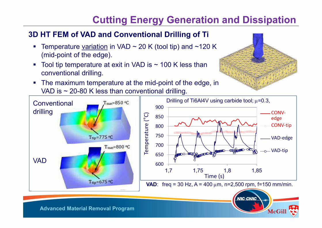
Temperature variation in VAD ~ 20 K (tool tip) and ~120 K (mid-point of the edge).
Tool tip temperature at exit in VAD is ~ 100 K less than conventional drilling.
The maximum temperature at the mid-point of the edge, in VAD is ~ 20-80 K less than conventional drilling.
VAD: freq = 30 Hz, A = 400 mm, n=2,500 rpm, f=150 mm/min.
Drilling of Ti6Al4V using carbide tool; m=0.3,
Cutting Energy Generation and Dissipation 3D HT FEM of VAD and Conventional Drilling of Ti
Conventional drilling
VAD
Advanced Material Removal Program McGill
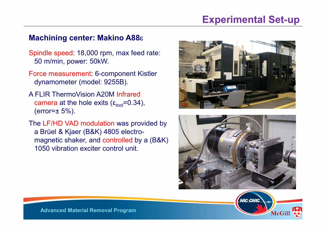
Experimental Set-upMachining center: Makino A88
Spindle speed: 18,000 rpm, max feed rate: 50 m/min, power: 50kW.
Force measurement: 6-component Kistler dynamometer (model: 9255B).
A FLIR ThermoVision A20M Infrared camera at the hole exits (εtool=0.34), (error=± 5%).
The LF/HD VAD modulation was provided by a Brüel & Kjaer (B&K) 4805 electro-magnetic shaker, and controlled by a (B&K) 1050 vibration exciter control unit.
Advanced Material Removal Program McGill
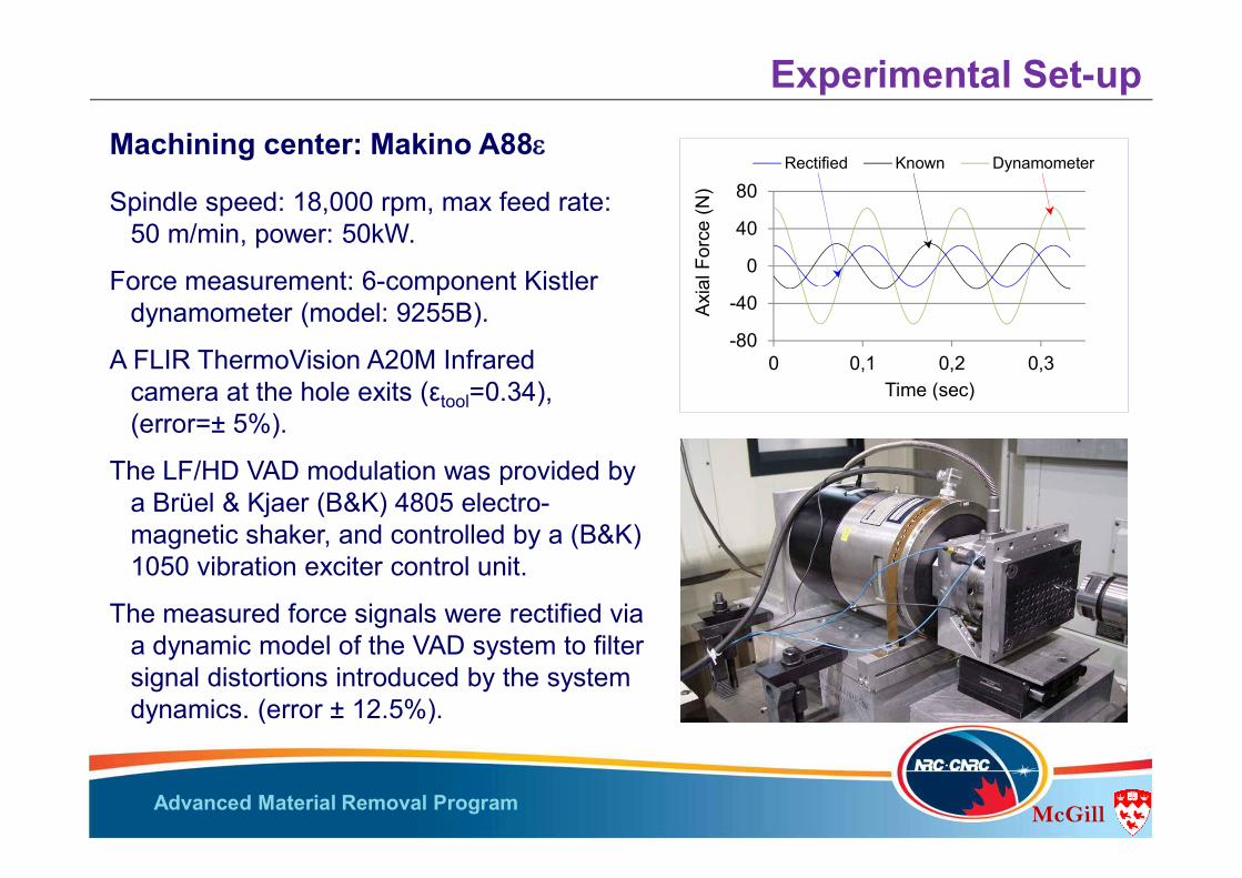
Experimental Set-upMachining center: Makino A88
Spindle speed: 18,000 rpm, max feed rate: 50 m/min, power: 50kW.
Force measurement: 6-component Kistler dynamometer (model: 9255B).
A FLIR ThermoVision A20M Infrared camera at the hole exits (εtool=0.34), (error=± 5%).
The LF/HD VAD modulation was provided by a Brüel & Kjaer (B&K) 4805 electro-magnetic shaker, and controlled by a (B&K) 1050 vibration exciter control unit.
The measured force signals were rectified via a dynamic model of the VAD system to filter signal distortions introduced by the system dynamics. (error ± 12.5%).
M1
K1
C1
M2
K2
C2
M3
K3
C3
M4
K4
C4
Work- Shaker
External Force
X1
Dynobaseplate
Dynofaceplate
X2X3X4
piece
-80
-40
0
40
80
0 0,1 0,2 0,3
Axi
al F
orce
(N)
Time (sec)
Rectified Known Dynamometer
Advanced Material Removal Program McGill
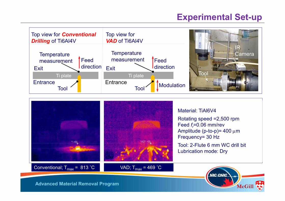
Experimental Set-up
Top view for ConventionalDrilling of Ti6Al4V
Exit
EntranceTi plate
Tool
Feed direction
Temperature measurement
Top view forVAD of Ti6Al4V
Exit
EntranceTi plate
Tool
Feed direction
Temperature measurement
Modulation
IR Camera
Tool
Conventional; Tmax = 813 ˚C VAD; Tmax = 469 ˚C
Material: TiAl6V4Rotating speed =2,500 rpmFeed fr=0.06 mm/revAmplitude (p-to-p)= 400 mm Frequency= 30 HzTool: 2-Flute 6 mm WC drill bitLubrication mode: Dry
Advanced Material Removal Program McGill
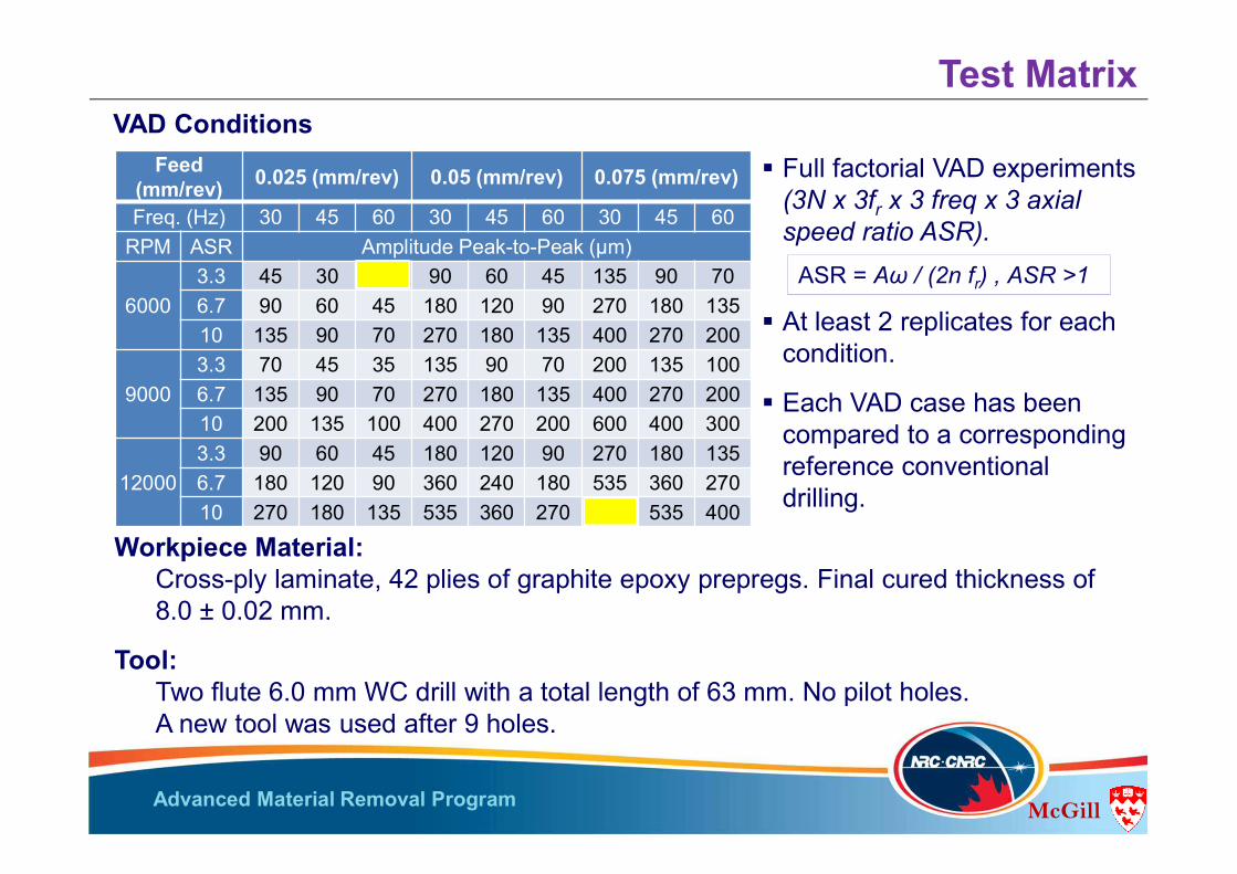
Full factorial VAD experiments (3N x 3fr x 3 freq x 3 axial speed ratio ASR).
At least 2 replicates for each condition.
Each VAD case has been compared to a corresponding reference conventional drilling.
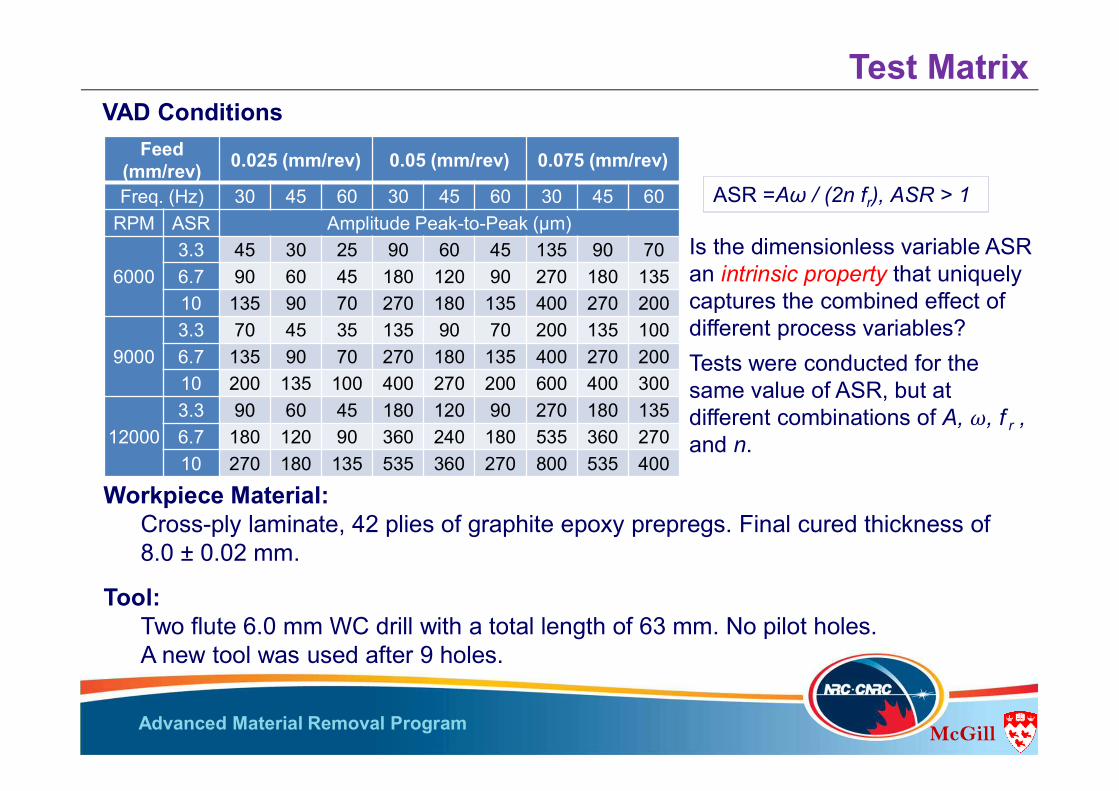
Test MatrixVAD Conditions
Workpiece Material: Cross-ply laminate, 42 plies of graphite epoxy prepregs. Final cured thickness of 8.0 ± 0.02 mm.
Tool: Two flute 6.0 mm WC drill with a total length of 63 mm. No pilot holes.A new tool was used after 9 holes.
ASR = Aω / (2n fr) , ASR >1
Feed (mm/rev) 0.025 (mm/rev) 0.05 (mm/rev) 0.075 (mm/rev)
Freq. (Hz) 30 45 60 30 45 60 30 45 60RPM ASR Amplitude Peak-to-Peak (μm)
60003.3 45 30 25 90 60 45 135 90 706.7 90 60 45 180 120 90 270 180 13510 135 90 70 270 180 135 400 270 200
90003.3 70 45 35 135 90 70 200 135 1006.7 135 90 70 270 180 135 400 270 20010 200 135 100 400 270 200 600 400 300
120003.3 90 60 45 180 120 90 270 180 1356.7 180 120 90 360 240 180 535 360 27010 270 180 135 535 360 270 800 535 400
Advanced Material Removal Program McGill
Is the dimensionless variable ASR an intrinsic property that uniquely captures the combined effect of different process variables?Tests were conducted for the same value of ASR, but at different combinations of A, ω, f r , and n.
Test Matrix
Workpiece Material: Cross-ply laminate, 42 plies of graphite epoxy prepregs. Final cured thickness of 8.0 ± 0.02 mm.
Tool: Two flute 6.0 mm WC drill with a total length of 63 mm. No pilot holes.A new tool was used after 9 holes.
ASR =Aω / (2n fr), ASR > 1
Feed (mm/rev) 0.025 (mm/rev) 0.05 (mm/rev) 0.075 (mm/rev)
Freq. (Hz) 30 45 60 30 45 60 30 45 60RPM ASR Amplitude Peak-to-Peak (μm)
60003.3 45 30 25 90 60 45 135 90 706.7 90 60 45 180 120 90 270 180 13510 135 90 70 270 180 135 400 270 200
90003.3 70 45 35 135 90 70 200 135 1006.7 135 90 70 270 180 135 400 270 20010 200 135 100 400 270 200 600 400 300
120003.3 90 60 45 180 120 90 270 180 1356.7 180 120 90 360 240 180 535 360 27010 270 180 135 535 360 270 800 535 400
VAD Conditions

Advanced Material Removal Program McGill
Axial forces “FA”: Feed has the most significant
effect on FA (+): Feed chip thickness and FA.
Rotational speed ‘n’ has the least effect on FA (-).
ASR causes FA
Different force levels obtained for the same ASR value; ASR is notan intrinsic property that can uniquely control the VAD forces.
Results: Drilling Forces
0
50
100
150
200
250
0.02
5
0.05
0.07
5
0.02
5
0.05
0.07
5
0.02
5
0.05
0.07
5
6000 9000 12000
Axia
l For
ce (N
)
ASR=3.3
ASR=6.7
ASR=10.0
0 0.5 1.0 1.5 2.0 2.5
200
160
120
80
40
0
Forc
e (N
)
Time (s)
Frequency = 30 Hz
Feed:
n (rpm):
n =12,000
f = 0.075
ASR = 10
��
f ( DoC) = f { wm / wT}
Advanced Material Removal Program McGill
Axial forces “FA”:
For a given ASR, moving horizontally: (amplitude + frequency ): DOC ,engagement time , FA.
Increasing ASR, moving down: (amplitude + same frequency and engagement time): DOC, FA
Compared to conventional drilling, FA (45% at min. ASR; gradual cutting; smaller A). FA (60% at max. ASR; higher A + maximum engagement).
0.025 mm/rev 0.05 mm/rev 0.075 mm/revFrequency (Hz)
30 60 30 60 30 603.3 -10.0 -19.7 -0.2 -11.7 -0.4 -10.66.7 0.8 -22.0 22.4 -10.7 21.5 -10.710.0 12.6 -18.5 39.0 -6.8 47.6 -2.13.3 0.2 -4.5 8.4 -1.7 9.6 -5.76.7 29.2 2.3 19.6 5.0 30.4 8.710.0 17.7 -8.6 28.9 -3.6 32.7 5.13.3 -37.7 -43.1 -11.7 -17.2 -6.4 -13.56.7 4.9 -27.9 11.5 -1.0 16.5 8.310.0 42.1 14.4 59.7 20.1 27.7 34.8
6000
9000
12000
Feed
rpm ASR
30 60 30 60 30 603.3 76.0 67.7 106.5 94.2 135.9 122.06.7 85.0 65.8 130.5 95.2 165.7 121.910.0 95.0 68.8 148.2 99.4 201.3 133.53.3 75.6 72.1 115.7 104.9 148.9 128.16.7 97.5 74.0 127.7 112.1 177.1 147.610.0 88.9 69.0 137.6 102.9 180.3 142.83.3 46.4 42.4 98.0 92.0 131.7 121.76.7 78.2 53.7 123.7 109.9 163.9 152.210.0 105.9 85.2 177.3 133.4 179.6 189.6
6000
9000
12000
Feed 0.025 mm/rev 0.05 mm/rev 0.075 mm/rev
rpm ASR Frequency (Hz)
< - 20%
>20%
>20%>20%
±10%
±10%±10%
±10%
125-200 N
75-125 N
75 –125 N
<75 N>125 N
150- 200 N
75 –125 N
125-200 N
125-200 N
125-200 N
125-200 N
<75 N<75 N
<75 N
Comparative axial force (VAD vs Conventional)
Absolute maximum axial force
Results: Drilling Forces
ASR = Aω / (2n f)
��� � ���2��
6000 6.7 90 45 180 90 270 135
60003.3 45 25 90 45 135 706.7 90 45 180 90 270 13510.0 135 70 270 135 400 200
Advanced Material Removal Program McGill
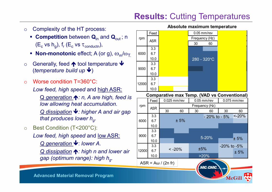
Comparative max Temp. (VAD vs Conventional)
Results: Cutting Temperatures
o Generally, feed tool temperature (temperature build up )
Feed
30 60 30 60 30 603.3 -2.4 1.1 -3.9 -13.4 -5.9 -21.76.7 0.1 4.1 0.9 -0.4 3.0 -5.210.0 -0.6 3.5 2.2 3.2 6.7 6.03.3 5.2 -0.3 8.5 11.0 10.0 18.86.7 13.1 14.6 18.1 9.3 7.6 1.710.0 4.9 5.9 9.8 13.4 2.3 -0.43.3 -49.4 -47.1 0.4 0.4 -8.0 -6.16.7 -20.5 -39.7 2.6 3.9 -10.0 0.510.0 2.8 -2.5 6.0 7.3 -15.5 -0.8
rpm0.025 mm/rev 0.05 mm/rev 0.075 mm/rev
ASR Frequency (Hz)
6000
9000
12000 < -20%
5-20%
± 5%
± 5%
± 5%-20% to -5%
- 20% to - 5% <-20%
±5%
>20%
Feed
30 60 30 60 30 603.3 313.8 328.9 293.2 270.1 262.8 213.56.7 311.9 323.4 299.4 285.2 273.8 248.210.0 306.3 322.6 293.6 291.0 259.5 270.83.3 333.6 329.2 308.6 312.8 276.0 300.06.7 362.1 377.3 331.2 310.6 282.9 286.210.0 308.3 342.9 300.1 306.0 266.5 257.93.3 171.8 184.8 290.3 292.6 268.7 265.96.7 289.1 183.9 292.2 299.0 260.0 277.510.0 329.8 356.3 299.5 307.9 252.5 275.5
rpm0.025 mm/rev 0.05 mm/rev 0.075 mm/rev
ASR Frequency (Hz)
6000
9000
12000<200 °C
320 -360°C
280 -320°C
280 - 320°C
240 - 280°C
240 -280°C
200 -240°C
320 -360°C
Absolute maximum temperature
ASR = Aω / (2n fr)
o Best Condition (T<200°C): Low feed, high speed and low ASR:
Q generation : lower A.Q dissipation : high n and lower air gap (optimum range): high hg.
o Worse condition T=360°C: Low feed, high speed and high ASR:
Q generation : n, A are high, feed is low allowing heat accumulation. Q dissipation : higher A and air gap that produces lower hg.
o Complexity of the HT process: Competition between Qin and Qout ; n
(Ec vs hg), fr (Ec vs tconductn), Non-monotonic effect; A (or g), wm/wT.

Advanced Material Removal Program McGill
Results: Delamination and thermal damage In all conventional drilling tests: Exit delamination + certain
degree of thermal damage observed. In all VAD tests: No noticeable thermal damage
Although 360oC was reached on the tool (not the wp); DT reduction during interrupted cutting > 100K. Upon re-engagement, Tc is further reduced < 280oC.
In VAD at low feeds: Delamination totally eliminated. Increase in delamination in the range of high feed, and low/
medium speeds.
Conventional Drilling Rotational speed 6,000 rpm
and f= 0.025 mm/rev
Matrix burnout
Uncut fibers
Feed
30 60 30 60 30 603.3 -0.1 -0.1 0.2 0.3 0.4 0.36.7 -0.1 -0.1 -0.1 0.1 0.3 0.3
10.0 -0.1 -0.1 0.1 0.1 0.1 0.33.3 -0.1 -0.1 0.1 -0.1 0.3 0.36.7 -0.1 -0.1 0.0 0.1 0.3 0.4
10.0 -0.1 -0.1 0.2 0.1 0.3 0.43.3 -0.1 -0.1 0.2 -0.1 0.1 0.06.7 -0.1 -0.1 -0.1 0.1 -0.1 0.2
10.0 -0.1 -0.1 0.0 0.2 0.1 0.2
0.025 mm/rev 0.05 mm/rev
9000
12000
rpm0.075 mm/rev
ASR Frequency (Hz)
6000
Delamination-free
Up to 20%
20% to 40%
Up to 20%
Up to 20%
Comparative exit delamination factor f VAD vs Conventional:
Dd
Dn
(f = (Dd - Dn)/ Dn
Advanced Material Removal Program McGill
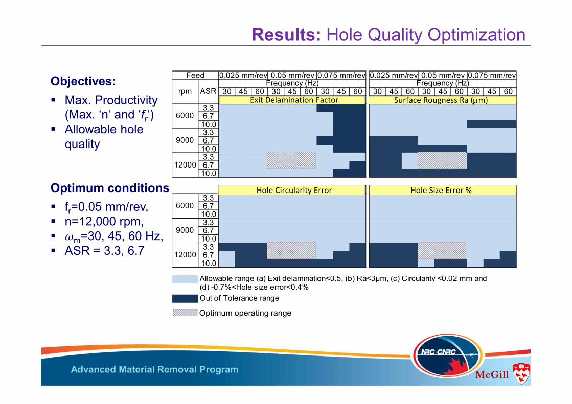
30 45 60 30 45 60 30 45 60 30 45 60 30 45 60 30 45 60
3.3 0.0 0.0 0.0 0.3 0.3 0.4 0.6 0.5 0.5 1.5 1.5 1.7 1.6 2.1 1.4 1.5 1.7 1.66.7 0.0 0.0 0.0 0.0 0.2 0.3 0.5 0.6 0.6 2.2 2.4 2.4 1.7 1.9 1.6 1.7 2.1 1.910.0 0.0 0.0 0.0 0.3 0.3 0.3 0.3 0.6 0.5 2.4 2.7 2.7 2.2 2.1 1.9 3.3 3.0 3.63.3 0.0 0.0 0.0 0.2 0.0 0.0 0.5 0.6 0.5 2.7 2.6 2.4 2.2 2.2 1.9 2.2 2.4 2.46.7 0.0 0.0 0.0 0.1 0.3 0.3 0.5 0.6 0.5 4.0 4.0 4.1 2.9 2.8 3.0 2.0 2.0 2.110.0 0.0 0.0 0.0 0.4 0.1 0.2 0.4 0.6 0.6 4.8 5.0 5.0 4.3 4.4 4.8 2.0 2.1 2.13.3 0.0 0.0 0.0 0.3 0.3 0.2 3.9 3.5 2.8 3.3 3.2 3.56.7 0.0 0.0 0.0 0.0 0.0 0.6 3.6 3.9 2.4 3.1 3.1 3.010.0 0.0 0.0 0.0 0.2 0.0 0.4 0.4 0.6 0.5 6.3 5.9 6.2 4.4 4.7 4.5 4.6 4.0 4.1
3.3 ### ### ### ### ### ### ### ### ### 0.0 0.0 0.0 -0.1 -0.1 -0.1 -0.1 -0.1 -0.16.7 ### ### ### ### ### ### ### ### ### 0.0 0.0 0.0 -0.1 -0.1 -0.1 -0.1 -0.2 -0.210.0 ### ### ### ### ### ### ### ### ### 0.0 0.0 0.0 0.0 -0.1 -0.1 -0.1 -0.2 -0.13.3 ### ### ### ### ### ### ### ### ### 0.0 0.0 0.0 -0.1 -0.1 -0.1 -0.2 -0.2 -0.26.7 ### ### ### ### ### ### ### ### ### 0.0 0.0 -0.1 -0.1 -0.1 -0.1 -0.1 -0.1 -0.110.0 ### ### ### ### ### ### ### ### ### 0.1 0.0 0.0 -0.1 0.0 0.0 -0.1 -0.1 -0.13.3 ### ### ### ### ### ### 6.3 6.2 6.4 0.3 0.3 0.36.7 ### ### ### ### ### ### 2.7 1.4 5.8 0.3 0.4 0.410.0 ### ### ### ### ### ### ### ### ### 0.6 0.4 2.9 0.2 0.6 0.6 0.3 0.5 0.5
Allowable range (a) Exit delamination<0.5, (b) Ra<3µm, (c) Circularity <0.02 mm and (d) -0.7%<Hole size error<0.4%Out of Tolerance range
9000
12000
6000
9000
12000
(c) Hole Circularity (mm) (a) Hole size error %
6000
0.075 mm/rev
rpm ASR Frequency (Hz) Frequency (Hz)
(a) Exit delamination factor (b) Surface roughness (Ra)
Feed 0.025 mm/rev 0.05 mm/rev 0.075 mm/rev 0.025 mm/rev 0.05 mm/rev
Optimum operating range
Objectives: Max. Productivity
(Max. ‘n‘ and ‘fr‘) Allowable hole
quality
Optimum conditions fr=0.05 mm/rev, n=12,000 rpm, m=30, 45, 60 Hz, ASR = 3.3, 6.7
Results: Hole Quality Optimization
Exit Delamination Factor Surface Rougness Ra (mm)
Hole Circularity Error Hole Size Error %
Advanced Material Removal Program McGill
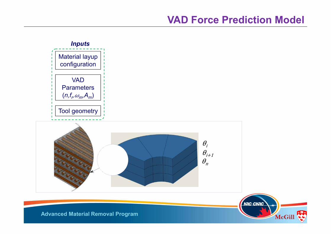
VAD Parameters(n,fr,�m,Am)
Tool geometry
Material layup configuration
Inputs
VAD Force Prediction Model
ii�1n
Advanced Material Removal Program McGill
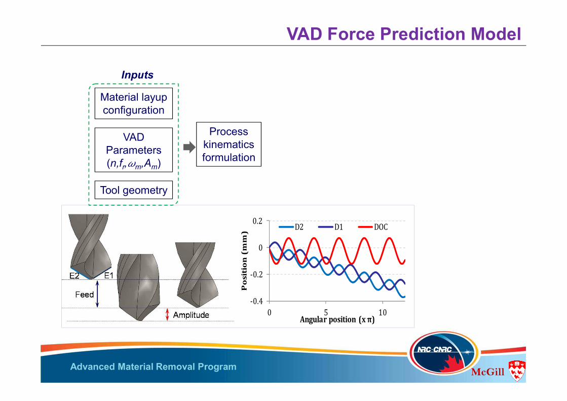
Process kinematics formulation
VAD Parameters(n,fr,�m,Am)
Tool geometry
Material layup configuration
Inputs
VAD Force Prediction Model
-0.4
-0.2
0
0.2
0 5 10
Position(mm)
Angularposition (xπ)
D2 D1 DOC

Advanced Material Removal Program McGill
Process kinematics formulation
VAD Parameters(n,fr,�m,Am)
Tool geometry
Material layup configuration
Inputs
Formed chip dynamic geometry
Cutting edge sections
VAD Force Prediction Model
ni
I +1
Tool-workpiece interaction
12 3
Relative tool –workpieceposition qe
eee
Advanced Material Removal Program McGill
0.050.1
0.150.2
0100
200300
0
200
400
600
Cut
ting
Pres
sure
(N/m
m2 )
feed (mm/rev)qe (deg)
Output:Predicted forces
and torques
Process kinematics formulation
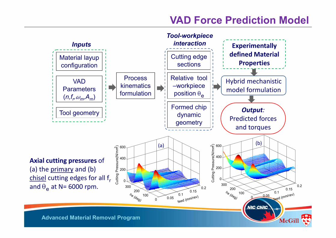
Hybrid mechanistic model formulation
VAD Parameters(n,fr,�m,Am)
Tool geometry
Material layup configuration
Inputs
Formed chip dynamic geometry
Cutting edge sections
Tool-workpiece interaction Experimentally
defined Material Properties
VAD Force Prediction Model
0.050.1
0.150.2
0100
200300
0
200
400
600
Cut
ting
Pres
sure
(N/m
m2 )
feed (mm/rev)qe (deg)
Axial cutting pressures of (a) the primary and (b) chisel cutting edges for all frand qe at N= 6000 rpm.
(a) (b)
Relative tool –workpieceposition qe

Advanced Material Removal Program McGill
00,10,20,30,40,50,6
1,50
1,52
1,55
1,58
1,61
1,64
1,66
1,69
1,72
1,75
1,78
1,80
Torq
ue (N
.m)
Time (s)
Measured Predicted
0,020,040,060,080,0
100,0120,0
1,50
1,52
1,55
1,58
1,61
1,64
1,66
1,69
1,72
1,75
1,78
1,80
Axia
l For
ce (N
)
Time (s)
Measured Predicted
Model Validation
fr=0.05 mm/rev, n=12,000 rpm,�m=30 Hz, Am= 0.09 mm
-25
-15
-5
5
15
25
30 60 30 60
0.090 0.135
Max
imum
forc
e er
ror %
Frequency (Hz)Amplitude (mm)
Steady State Entrance Exit
-25
-15
-5
5
15
25
30 60 30 60
0.090 0.135
Max
imum
torq
ue e
rror
%
Frequency (Hz)Amplitude (mm)

Advanced Material Removal Program McGill
1. The force reduction in the Intermittent cutting in VAD is achieved through the progressive removal of the formed chip, provided that A is moderate w.r.t. DOC.
2. The thermal performance of the VAD process is enhanced by the formation of vortices in the air gap created by the tool separation.
3. The axial speed ratio ASR is not intrinsic property and cannot uniquely define the cutting temperature and force in VAD.
4. The VAD process can eliminate exit delamination and thermal damage (al low/ medium feeds).
5. Generally, the optimum range of LFHA-VAD is defined by the combination of high speed with low-to-medium feed, low ASR and high frequency.
6. A novel semi analytical model was developed to accurately predict the transient features of the forces in conventional and VAD, considering the effects of: Process variables. Material layup configurations (on the chip formation mechanism). Material deformation during drilling. Tool geometry ad rake angle variation along the primary cutting edge.
Concluding Remarks

Advanced Material Removal Program
Vielen Dank für Ihere Aufmerksamkeit!