A ROLE AND ATTRIBUTE BASED ENCRYPTION APPROACH …dservos5/Daniel_Servos_Thesis_V8.pdf · 4.2.3...
241
A ROLE AND ATTRIBUTE BASED ENCRYPTION APPROACH TO PRIVACY AND SECURITY IN CLOUD BASED HEALTH SERVICES by Daniel Servos A thesis submitted to the faculty of graduate studies Lakehead University in partial fulfillment of the requirements for the degree of Master of Science in Computer Science Department of Computer Science Lakehead University April 2012 Copyright © Daniel Servos 2012
Transcript of A ROLE AND ATTRIBUTE BASED ENCRYPTION APPROACH …dservos5/Daniel_Servos_Thesis_V8.pdf · 4.2.3...
A ROLE AND ATTRIBUTE BASED ENCRYPTION
APPROACH TO PRIVACY AND SECURITY IN CLOUD
BASED HEALTH SERVICES
by
Daniel Servos
A thesis submitted to the faculty of graduate studies
Lakehead University
in partial fulfillment of the requirements for the degree of
Master of Science in Computer Science
Department of Computer Science
Lakehead University
April 2012
Copyright © Daniel Servos 2012
Lakehead
UNIVERSITY
OFFICE OF GRADUATE STUDIES
—————————————————————
NAME OF STUDENT: Daniel Servos
DEGREE AWARDED: Masters of Science in Computer Science
ACADEMIC UNIT: Department of Computer Science
TITLE OF THESIS: A ROLE AND ATTRIBUTE BASED ENCRYPTION
APPROACH TO PRIVACY AND SECURITY IN CLOUD
BASED HEALTH SERVICES
This thesis has been prepared
under my supervision
and the candidate has complied
with the Master’s regulations.
———————————-
Signature of Supervisor
—————————
Date
Contents
1 Introduction ................................................................................................................1
1.1 Background Information .......................................................................................... 1
1.1.1 Cloud Computing ......................................................................................................... 2
1.1.2 Distributed OSGi .......................................................................................................... 4
1.1.3 Role Based Access Control .......................................................................................... 6
1.1.4 Identity and Attribute Based Cryptography .................................................................. 8
1.2 The Cloud Problem .................................................................................................. 9
1.3 Cloud Security Approaches and Techniques ......................................................... 16
1.3.1 Privacy as a Service: Privacy-Aware Data Storage and Processing in Cloud
Computing Architectures (Itani, Kayssi, & Chehab, 2009) ................................................. 17
1.3.1.1 Summary .......................................................................................................... 17
1.3.1.2 Criticisms ......................................................................................................... 20
1.3.2 A Privacy Manager for Cloud Computing (Pearson, Shen, & Mowbray, 2009) ........ 21
1.3.2.1 Summary .......................................................................................................... 21
1.3.2.2 Criticisms ......................................................................................................... 22
1.3.3 Towards Trusted Cloud Computing (Santos, Gummadi, & Rodrigues, 2009) ........... 23
1.3.3.1 Summary .......................................................................................................... 23
1.3.3.2 Criticisms ......................................................................................................... 26
1.5 Towards Cloud Security and Privacy for Sharing EHRs ....................................... 27
1.6 Thesis Layout ......................................................................................................... 30
2 Constructing A Cloud Based Infrastructure for Sharing Health Records (HCX) ....33
2.1 EHR Specifications ................................................................................................ 33
2.1.1 Continuity of Care Record .......................................................................................... 33
2.1.2 Continuity of Care Document ..................................................................................... 36
2.1.3 Others.......................................................................................................................... 37
2.2 HCX Architecture .................................................................................................. 38
2.2.1 Services ....................................................................................................................... 39
2.2.1.1 EHRProvider ................................................................................................... 42
2.2.1.2 EHRManager ................................................................................................... 44
2.2.1.3 EHRPortal ........................................................................................................ 45
2.2.1.4 Administrative ................................................................................................. 47
2.2.1.5 AuditLog .......................................................................................................... 47
2.2.2 Clients ......................................................................................................................... 48
2.3 HCX Implementation ............................................................................................. 49
2.3.1 DOSGi Infrastructure ................................................................................................. 49
2.3.2 Cloud Infrastructure .................................................................................................... 52
2.4 Conclusions ............................................................................................................ 54
3 Developing a Role Based Access Control and Single-Sign-On System for the Cloud55
3.1 Role Based Access Control .................................................................................... 55
3.1.1 RBAC Related Research............................................................................................. 56
3.1.1.1 The ANSI RBAC Standard .............................................................................. 58
3.1.1.1.1 Summary ................................................................................................................. 58 3.1.1.1.2 Criticisms ................................................................................................................ 62
3.1.1.2 OASIS Role-Based Access Control ................................................................. 72
3.1.1.2.1 Summary ................................................................................................................. 72 3.1.1.2.2 Criticisms ................................................................................................................ 74
3.1.2 A New Take on RBAC (RBAC as a Service) ............................................................ 80
3.1.2.1 Introduction ..................................................................................................... 80
3.1.2.2 Model Description ........................................................................................... 81
3.1.2.2.1 Namespace .............................................................................................................. 85 3.1.2.2.1 Parameterization and Conditions ............................................................................. 87
3.1.2.2.2 Sessions ................................................................................................................... 90 3.1.2.2.3 Constraints .............................................................................................................. 92 3.1.2.2.4 Negative Permissions and Roles ............................................................................. 92 3.1.2.2.5 Revocation .............................................................................................................. 92 3.1.2.2.6 Distributed Function................................................................................................ 93 3.1.2.2.7 Web Service Interfaces, Client API and Formal Description .................................. 98 3.1.2.2.8 Permissions Set and Role List Caching ................................................................... 98 3.1.2.2.9 Example Use Case .................................................................................................. 99
3.2 Single Sign On ..................................................................................................... 104
3.2.1 RBSSO Description .................................................................................................. 104
3.2.1.1 Authentication Servers................................................................................... 106
3.2.1.2 Service Controllers ........................................................................................ 107
3.2.1.3 Cloud Based Services .................................................................................... 108
3.2.1.4 Protocol .......................................................................................................... 109
3.2.2 Performance Evaluation ............................................................................................ 114
3.3 Conclusions .......................................................................................................... 117
4 Cloud Privacy Through Attribute Based Encryption .............................................119
4.1 Introduction .......................................................................................................... 119
4.1.1 Data Privacy on the Cloud ........................................................................................ 119
4.1.2 Pairing-Based Cryptography .................................................................................... 121
4.1.3 Identity Based and Attribute Based Encryption ....................................................... 122
4.2 Attribute Based Encryption Related Research ..................................................... 125
4.2.1 Fuzzy Identity-Based Encryption (Sahai & Waters, 2005) ...................................... 125
4.2.1.1 Summary ........................................................................................................ 125
4.2.1.2 Criticisms ....................................................................................................... 127
4.2.2 Attribute-Based Encryption for Fine-Grained Access Control of Encrypted Data
(Goyal, Pandey, Sahai, & Waters, 2006) ........................................................................... 129
4.2.2.1 Summary ........................................................................................................ 129
4.2.2.2 Criticisms ....................................................................................................... 132
4.2.3 Ciphertext-policy attribute-based encryption (Bethencourt, Sahai, & Waters, 2007)
........................................................................................................................................... 134
4.2.3.1 Summary ........................................................................................................ 134
4.2.3.2 Criticisms ....................................................................................................... 138
4.2.4 Self-Protecting Electronic Medical Records Using Attribute-Based Encryption
(Akinyele, Lehmann, Green, Pagano, Peterson, & Rubin, 2010) ...................................... 140
4.2.4.1 Summary ........................................................................................................ 140
4.2.4.2 Criticisms ....................................................................................................... 142
4.3 Distributed Multi-Authority Ciphertext-Policy Shared Attribute-Based Encryption
(DMACPSABE) ......................................................................................................... 144
4.3.1 Introduction .............................................................................................................. 144
4.3.2 Constructions ............................................................................................................ 145
4.3.2.1 Authority Hierarchy ....................................................................................... 146
4.3.2.2 Setup .............................................................................................................. 147
4.3.2.3 User Keygen .................................................................................................. 150
4.3.2.4 Encryption and Decryption ............................................................................ 151
4.3.2.5 Adding/Removing Authorities and Attribute Sets ......................................... 152
4.3.2.6 Not Equals ..................................................................................................... 153
4.3.2.7 User Origin .................................................................................................... 154
4.3.2.8 Human Readable Attributes ........................................................................... 155
4.3.2.9 Revocation and Expiration ............................................................................ 157
4.3.3 Protocol ..................................................................................................................... 158
4.3.3.1 Master Initialization ....................................................................................... 158
4.3.3.2 Authority User Key Delegation ..................................................................... 159
4.3.3.3 Encryption ..................................................................................................... 160
4.3.3.4 Decryption ..................................................................................................... 161
4.4 Implementation & Evaluation .............................................................................. 163
4.4.1 Implementation Details ............................................................................................. 163
4.4.2 Performance Evaluation ............................................................................................ 165
4.4.3 Possible Performance Improvements ....................................................................... 170
4.4.4 Security ..................................................................................................................... 173
4.6 Conclusions .......................................................................................................... 174
5 Conclusions ............................................................................................................175
5.1 Putting it all Together ........................................................................................... 175
5.1.1 RBACaaS Integration with DMACPSABE .............................................................. 175
5.1.2 Searching DMACPSABE Encrypted Files (HCX Integration) ................................ 181
5.1.3 HCX Integration with RBACaaS and RBSSO ......................................................... 183
5.1.4 Extensions to CCR and other XML formats ............................................................. 184
5.1.5 System Overview ...................................................................................................... 187
5.2 Future Work ......................................................................................................... 190
5.2.1 Automated Policy Discovery/Creation ..................................................................... 190
5.2.2 Automated Role and Permission Discovery ............................................................. 191
5.2.3 Automatic Role Activation ....................................................................................... 191
5.2.4 Explore Alternative Hierarchy Structures................................................................. 192
5.2.5 Explore Alternative Access Control Models ............................................................ 192
5.2.6 Removal of the Master Attribute Authority .............................................................. 193
5.2.7 Human Readable Attribute Names ........................................................................... 194
5.2.8 Searchable DMACPSABE ....................................................................................... 194
5.2.9 DMACPSABE Based Signing .................................................................................. 195
5.2.10 Fully Secure XML Extensions ................................................................................ 195
5.2.11 Mobile Support ....................................................................................................... 196
5.2.12 Real World Implementation and Use ..................................................................... 196
5.3 Conclusions .......................................................................................................... 197
A. HCX Interfaces ...................................................................................................... 199
A.1 EHRProvider ............................................................................................................... 199
A.2 EHRManager .............................................................................................................. 199
A.3 EHRPortal ................................................................................................................... 200
A.4 AuditLog ..................................................................................................................... 201
B. RBACaaS Web Interface ....................................................................................... 201
B.1 RBAC Service ............................................................................................................. 201
B.2 Administrative Service ................................................................................................ 202
B.2.1 Administrative Permissions ............................................................................. 202
B.2.2 Administrative Interface .................................................................................. 204
C. RBACaaS Client API ............................................................................................ 205
D. RBACaaS Formal Description .............................................................................. 207
D.1 RBAC Elements .......................................................................................................... 207
D.2 RBAC Relations ......................................................................................................... 207
D.3 Core Functions ............................................................................................................ 209
D.4 Cache Computation Functions .................................................................................... 211
D.5 Administrative functions............................................................................................. 212
List of Tables
TABLE 1.1: CHAPTER SUMMARIES...................................................................................... 32
TABLE 3.1: DEFAULT SYSTEM PARAMETERS. ..................................................................... 90
TABLE 3.2: TABLE OF PERMISSIONS REQUIRED FOR 1ST
RBACAAS USE CASE. ................ 101
TABLE 3.3: TABLE OF ROLES REQUIRED FOR 1ST
RBACAAS USE CASE. ............................ 101
TABLE 3.4: TABLE OF ENCRYPTION POLICES FOR 1ST
RBACAAS USE CASE. ..................... 102
TABLE 3.5: TABLE OF EDIT POLICES FOR THE 1ST
RBACAAS USE CASE. ........................... 103
TABLE 4.1: TABLE SHOWING THE EQUIVALENT CONSTANT ATTRIBUTES FOR A GIVEN SET OF
VARIABLE ATTRIBUTES. ASSUMING INT_MAX OF 15 (I.E. 4 BIT VARIABLE VALUES).
................................................................................................................................. 150
TABLE 5.1: TABLE OF DEFAULT ATTRIBUTES FOR THE ROOT DOMAIN. ............................. 178
TABLE 5.2: LIST OF RULES TO BE ADDED TO DMACPSABE DECRYPTION POLICIES. ....... 180
List of Figures
FIGURE 1.1: CLOUD COMPUTING LAYERS. ............................................................................ 4
FIGURE 1.2: BASIC RBAC MODEL. ...................................................................................... 7
FIGURE 2.1: EXAMPLE CCR DOCUMENT FOR FICTIONAL PATIENT JOHN DOE CONTAINING
THE RESULTS OF A BLOOD PRESSURE TEST. ................................................................ 35
FIGURE 2.2: EXAMPLE XSL TRANSFORMED CCR DOCUMENT USING XSL
TRANSFORMATION FROM THE CCR ACCELERATION RESOURCES PROJECT
(HTTP://SOURCEFORGE.NET/PROJECTS/CCR-RESOURCES/). ......................................... 36
FIGURE 2.3: SERVICE CONTROLLER AND REGISTRY INTERACTIONS. DOTTED ARROWS LINES
INDICATE INTERACTIONS TRANSPARENT TO SERVICE CONSUMERS. ............................ 40
FIGURE 2.4: AUDITLOG INTERACTIONS. 1. CLIENT/SERVICE CONSUMER MAKES A REQUEST
ON A SERVICE. 2. THE SERVICE SENDS THE REQUESTTOKEN, AUDITTOKEN AND
REQUEST SUMMARY TO THE AUDITLOG SERVICE. 3. THE AUDITLOG SERVICE STORES A
LOG ENTRY FOR THE REQUEST ON CLOUD STORAGE. .................................................. 48
FIGURE 2.5: THE APACHE CXF DOSGI SERVICE DISCOVERY. .......................................... 50
FIGURE 2.6: XEN BASED MACHINE IMAGES TO SUPPORT DOSGI ON THE CLOUD. ............... 51
FIGURE 2.7: MACHINE INSTANCE INTERACTION TO SUPPORT DOSGI ON THE CLOUD. ...... 52
FIGURE 2.8: HCX EUCALYPTUS PRIVATE CLOUD SET-UP ................................................. 53
FIGURE 3.1: ANSI INCITS 359-2004 CORE RBAC MODEL.............................................. 59
FIGURE 3.2: GENERAL INHERITANCE HIERARCHICAL RBAC ............................................. 61
FIGURE 3.3: SSD RBAC .................................................................................................... 61
FIGURE 3.4: DSD RBAC ................................................................................................... 62
FIGURE 3.5: ANSI RBAC INHERITANCE OPERATIONS ON ROLE HIERARCHIES A AND B. ... 64
FIGURE 3.6: RBACAAS MODEL. ....................................................................................... 81
FIGURE 3.7: EXAMPLE GROUP TREE. ALL GROUPS DESCEND FROM THE ROOT GROUP WHICH
CONTAINS NO ROLES OR CONDITIONS. ........................................................................ 83
FIGURE 3.8: EXAMPLE ROLE TREE. ALL ROLES DESCEND FROM THE ROOT ROLE WHICH
CONTAINS NO PERMISSIONS. ....................................................................................... 84
FIGURE 3.9: EXAMPLE NAMESPACE ENFORCED PERMISSIONS TREE. ALL PERMISSIONS
DESCEND FROM THE ‘*’ PERMISSION NODE. ................................................................ 85
FIGURE 3.10: RBAC URI GRAMMAR. ................................................................................ 85
FIGURE 3.11: CONDITION GRAMMAR. ................................................................................ 88
FIGURE 3.12: EXAMPLE RBAC SERVICE HIERARCHY. ....................................................... 96
FIGURE 3.13: GRAMMAR FOR HASPERMISSION BOOLEAN STATEMENT. NOTE THAT PERM_ID
IS FROM FIGURE 3.10. ................................................................................................ 97
FIGURE 3.14: EXAMPLE RBSSO SYSTEM LAYOUT SHARING SEVERAL CLOUD BASED
SERVICES ON A PUBLIC CLOUD BETWEEN A HOSPITAL AND DOCTORS OFFICE. NOTE
THAT THE TRUSTED NETWORK COULD ALSO BE LOCATED IN THE DOCTOR’S OFFICE OR
HOSPITAL NETWORK. ................................................................................................ 107
FIGURE 3.15: RBSSO PROTOCOL SEQUENCE. .................................................................. 109
FIGURE 3.16: SERVICETOKEN PROTOCOL DIAGRAM ......................................................... 112
FIGURE 3.17: AUTHREQUEST PROTOCOL DIAGRAM. ........................................................ 113
FIGURE 3.18: AUTHTOKEN PROTOCOL DIAGRAM. ............................................................ 113
FIGURE 3.19: SESSIONKEY PROTOCOL DIAGRAM. ............................................................ 114
FIGURE 3.20: REQUESTTOKEN PROTOCOL DIAGRAM ....................................................... 114
FIGURE 3.21: AVERAGE TIME (IN MILLISECONDS) REQUIRED TO COMPLETE AND VERIFY AN
AUTHENTICATION REQUEST USING EACH PROTOCOL. BASED ON 10,000 REQUESTS. 116
FIGURE 3.22: AVERAGE TIME (IN MILLISECONDS) REQUIRED TO COMPLETE AND VERIFY AN
AUTHENTICATION REQUEST OVER THE WAN CONNECTION. BASED ON 1000 REQUESTS
PER RUN. .................................................................................................................. 116
FIGURE 3.23: AVERAGE TIME (IN MILLISECONDS) REQUIRED TO COMPLETE AND VERIFY AN
AUTHENTICATION REQUEST OVER THE LAN CONNECTION. BASED ON 1000 REQUESTS
PER RUN. .................................................................................................................. 117
FIGURE 4.1: IDENTITY-BASED ENCRYPTION CRYPTOLOGIC PROTOCOL. ........................... 123
FIGURE 4.2: CP-ABE POLICY TREE F OR ACCESS_LEVEL > 5 ........................................... 135
FIGURE 4.3: DIAGRAM OF COMPONENTS FROM (AKINYELE, LEHMANN, GREEN, PAGANO,
PETERSON, & RUBIN, 2010). .................................................................................... 142
FIGURE 4.4: EXAMPLE AUTHORITY HIERARCHY WITH LOGICAL AUTHORITIES ROOT, AND
AUTH2, AND REAL AUTHORITIES AUTH1, AUTH3 .. AUTH6. ....................................... 146
FIGURE 4.5: ACCESS TREE FOR USER_ID ≠ 4 ..................................................................... 154
FIGURE 4.6: POLICY TREE FOR ROOT_V1 ≥ 5. ................................................................... 160
FIGURE 4.7: POLICY TREE REQUIREMENT MET BY USKALICE. ............................................ 161
FIGURE 4.8: POLICY TREE REQUIREMENT MET BY USKBOB. .............................................. 162
FIGURE 4.9: FAILURE OF USKEVE TO SATISFY THE POLICY TREE Τ. ................................... 163
FIGURE 4.10: ATTRIBUTE AUTHORITY KEY SIZE VS NUMBER OF VARIABLE AND CONSTANT
ATTRIBUTES. ............................................................................................................ 164
FIGURE 4.11: CONSTANT ATTRIBUTES REQUIRED TO REPRESENT A GIVEN NUMBER OF
VARIABLE ATTRIBUTES IN A DMACPSABE AUTHORITY KEY AND A CP-ABE USER
KEY. ......................................................................................................................... 166
FIGURE 4.12: SIZE OF A DMACPSABE AUTHORITY KEY VS. THE SIZE OF A CP-ABE USER
KEY IN MEGABYTES FOR A INT_MAX OF 264
. .......................................................... 167
FIGURE 4.13: TIME TO GENERATE AN ATTRIBUTE AUTHORITY KEY IN SECONDS VS. NUMBER
OF VARIABLE AND CONSTANT ATTRIBUTE. ............................................................... 168
FIGURE 4.14: TIME TO GENERATE USER KEY IN CP-ABE AND DMACPSABE IN SECONDS
VS NUMBER OF VARIABLE ATTRIBUTES. ................................................................... 169
FIGURE 4.15: TIME TO GENERATE DMACPSABE USER KEY IN SECONDS VS NUMBER OF
ATTRIBUTES IN THE AUTHORITY KEY FOR A CONSTANT NUMBER OF ATTRIBUTES IN THE
USER KEY. ................................................................................................................ 170
FIGURE 4.16: TIME TO GENERATE DMACPSABE AUTHORITY KEY WITH STANDARD AND
PARALLELIZED FUNCTIONS. ...................................................................................... 172
FIGURE 4.17: TIME TO GENERATE A DMACPSABE OR CP-ABE USER KEY WITH
STANDARD AND PARALLELIZED FUNCTIONS. ............................................................ 173
FIGURE 5.1: RBAC SERVICE AND DMACPSABE ATTRIBUTE HIERARCHIES MERGED. ... 176
FIGURE 5.2: RBACAAS MODEL WITH SUPPORT FOR DMACPSABE ADDED. .................. 176
FIGURE 5.3: DMACPSABE XML FORMAT EXTENSION ................................................ 185
FIGURE 5.4: SYSTEM OVERVIEW ...................................................................................... 189
THE FOLLOWING ARE THE CRITICAL FUNCTIONS PROVIDED BY THE RBACAAS CLIENT SIDE
API WHICH CLOUD SERVICES MAY USE TO ENFORCE RBACAAS ACCESS CONTROLS
BASED ON A GIVEN BOOLEAN PERMISSION STATEMENT (SEE FIGURE 5.5): ............... 205
List of Equations
EQUATION 4.1: FIBE SETUP FUNCTION ............................................................................ 126
EQUATION 4.2: FIBE KEYGENERATION FUNCTION .......................................................... 126
EQUATION 4.3: FIBE ENCRYPTION FUNCTION ................................................................. 127
EQUATION 4.4: FIBE DECRYPTION FUNCTION ................................................................. 127
EQUATION 4.5: KP-ABE ENCRYPTION FUNCTION. .......................................................... 131
EQUATION 4.6: KP-ABE KEYGENERATION FUNCTION. ................................................... 131
EQUATION 4.7: KP-ABE DECRYPTION FUNCTION. .......................................................... 131
EQUATION 4.8: KP-ABE RECURSIVE DECRYPTNODE FUNCTION. .................................... 132
EQUATION 4.9: SETUP FUNCTION ..................................................................................... 136
EQUATION 4.10: ENCRYPT FUNCTION .............................................................................. 136
EQUATION 4.11: KEYGEN FUNCTION .............................................................................. 137
EQUATION 4.12: DECRYPTION FUNCTION ........................................................................ 137
EQUATION 4.13: RECURSIVE DECRYPTNODE FUNCTION ................................................. 137
EQUATION 4.14: DELEGATE FUNCTION ............................................................................ 138
EQUATION 4.15: DMACPSABE SETUP FUNCTION ......................................................... 148
EQUATION 4.16: RECURSIVE DMACPSABE AUTHATTSET FUNCTION .......................... 148
EQUATION 4.17: DMACPSABE USERKEYGEN FUNCTION ............................................. 151
EQUATION 4.18: PARALLELIZED VERSION OF THE KEYGEN FUNCTION. ......................... 171
EQUATION 4.19: KEYGEN_COMPUTE FUNCTION TO BE RUN IN PARALLEL. ........................ 171
EQUATION 4.20: PARALLELIZED VERSION OF THE USERKEYGEN FUNCTION. .................. 171

EQUATION 4.21: USERKEYGEN_COMPUTE FUNCTION TO BE RUN IN PARALLEL. ............... 171
Publications Arising From this Thesis
The research presented in this thesis has been published in part in the following
papers to date:
Sabah Mohammed, Daniel Servos, and Jinan Fiaidhi (2010). HCX: A Distributed OSGi
Based Web Interaction System for Sharing Health Records in the Cloud. In Proceedings
of the 2010 IEEE/WIC/ACM International Conference on Web Intelligence and
Intelligent Agent Technology - Volume 03, 102-107. (Chapter 2)
Sabah Mohammed, Daniel Servos, and Jinan Fiaidhi (2011). Developing a Secure
Distributed OSGi Cloud Computing Infrastructure for Sharing Health Records.
Autonomous and Intelligent Systems, Lecture Notes in Computer Science Volume: 6752,
241-252. (Chapter 2 and 3.2)
Future publications are planned for the contents of chapter 4 and possibly 3.1.
Abstract
Cloud computing is a rapidly emerging computing paradigm which replaces static and
expensive data centers, network and software infrastructure with dynamically scalable “cloud
based” services offered by third party providers on an on-demand basis. However, with the
potential for seemingly limitless scalability and reduced infrastructure costs comes new issues
regarding security and privacy as processing and storage tasks are delegated to potentially
untrustworthy cloud providers. For the eHealth industry this loss of control makes adopting the
cloud problematic when compliance with privacy laws (such HIPAA, PIPEDA and PHIPA) is
required and limits third party access to patient records.
This thesis presents a RBAC enabled solution to cloud privacy and security issues
resulting from this loss of control to a potentially untrustworthy third party cloud provider, which
remains both scalable and distributed. This is accomplished through four major components
presented, implemented and evaluated within this thesis; the DOSGi based Health Cloud
eXchange (HCX) architecture for managing and exchanging EHRs between authorized users, the
Role Based Access Control as a Service (RBACaaS) model and web service providing RBAC
policy enforcement and services to cloud applications, the Role Based Single Sign On (RBSSO)
protocol, and the Distributed Multi-Authority Ciphertext-Policy Shared Attribute-Based
Encryption (DMACPSABE) scheme for limiting access to sensitive records dependent on
attributes (or roles) assigned to users. We show that when these components are combined the
resulting system is both scalable (scaling at least linearly with users, request, records and
attributes), secure and provides a level of protection from the cloud provider which preserves the
privacy of user’s records from any third party. Additionally, potential use cases are presented for
each component as well as the overall system.

1
Chapter 1
1 Introduction
The increasingly popular cloud computing paradigm brings new opportunities to
reduce hardware, maintenance and network costs associated with the traditional
infrastructure required to offer large scale internet based services or even smaller
localized application and storage solutions. However, with the dynamic scalability,
reduced risk and potential cost savings comes a loss of control that creates new
challenges for adopting cloud based infrastructure. For the health care industry, the need
for cost efficient and low maintenance Electronic Health Record (EHR) systems is clear
(Urowitz, et al., 2008). However, data privacy, security and compliance with local and
global privacy laws are significant barriers blocking adoption of public cloud offerings.
This thesis presents work towards a potential solution to the problem of cloud privacy
and security in public, private, and hybrid cloud environments including protection for
transmission and storage of documents in situations where access to online services may
be limited or impossible. Additionally, methods for adapting Distributed OSGi (DOSGi)
for cloud based environments are detailed and a DOSGi framework for sharing health
records is presented.
1.1 Background Information
Subject areas including cloud computing, role based access control, and identity
and attribute based cryptology are covered in this thesis. The following sub-sections give
2
a brief overview and background in each area as well as a description of the DOSGi
platform used in chapter 2.
1.1.1 Cloud Computing
Due to the increased popularity in using “cloud computing” as a buzzword for any
web based application or service, a single unified definition of “cloud computing” has
become increasingly hard to arrive at. Multiple differing definitions have been used in
both scientific and business literature (Geelan, 2008) to describe both the applications
delivered through the cloud as well as the hardware and systems that comprise it.
However, some work has been done to come to a standardized definition, such as the
editorial note by LM. Vaquero, et al (2008). which presented the following proposed
definition:
“Clouds are a large pool of easily usable and accessible virtualized resources (such
as hardware, development platforms and/or services). These resources can be
dynamically reconfigured to adjust to a variable load (scale), allowing also for an
optimum resource utilization. This pool of resources is typically exploited by a pay-
per-use model in which guarantees are offered by the Infrastructure Provider by
means of customized SLAs.” (Vaquero & al., 2008)
For the purposes of this thesis the definition of Cloud Computing offered by R. Buyya, et
al. (2008) will be used where Cloud Computing is concerned:
“...a type of parallel and distributed system consisting of a collection of interconnected
and virtualised computers that are dynamically provisioned and presented as one or
more unified computing resources based on service-level agreements established
through negotiation between the service provider and consumers” (Buyya, Yeo, &
Venugopal, 2008)
A large driving force in the adoption of Cloud Computing is the increased interest
3
by businesses in utility computing over owning and operating their own data centres and
computer resources. In the utility computing model, Software, Platform and
Infrastructure are sold in a similar way as traditional utilities such as power, water, and
gas. Businesses are charged based on the amount of resources used and the length of time
they are utilized. An example would be Amazon's EC2 service (http://aws.amazon.com/),
where businesses are charged based on the amount of time an instance (a virtual machine)
is active as well as the amount of resources used (e.g. the amount of RAM, number of
CPUs, etc. being used by an active instance). When such services are sold to the public,
the cloud is deemed to be a “public cloud”. Offering public cloud services allows
companies such as Amazon and Google who have vast computing and network resources
for their core business functions, to leverage their existing infrastructure (which may be
largely underutilized at off peak times) to businesses and organizations that have a
limited or nonexistent infrastructure. Alternatively, organizations may operate their own
“private cloud” for internal use or a hybrid system involving both public and private
components.
For the healthcare industry, cloud computing offers the potential to enable
patients, physicians, healthcare workers and administrators immediate access to a wide
range of healthcare resources, applications and tools. For hospitals, physician practices
and emergency medical service providers, the lowered initial investment and the
elimination of data center, hardware, and related IT costs offered by cloud computing can
help overcome the financial barriers blocking the wide adoption of EHR systems
(Urowitz, et al., 2008) and provide the infrastructure needed to make patient accessible
records possible in a secure manner.
4
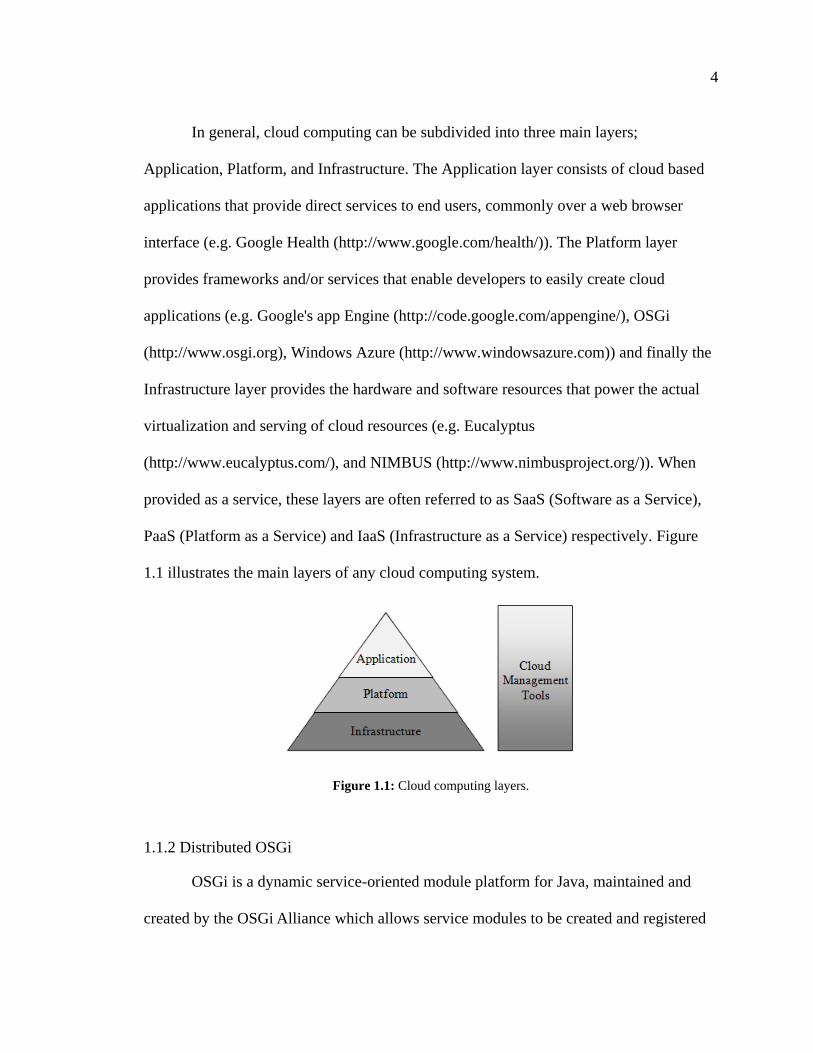
In general, cloud computing can be subdivided into three main layers;
Application, Platform, and Infrastructure. The Application layer consists of cloud based
applications that provide direct services to end users, commonly over a web browser
interface (e.g. Google Health (http://www.google.com/health/)). The Platform layer
provides frameworks and/or services that enable developers to easily create cloud
applications (e.g. Google's app Engine (http://code.google.com/appengine/), OSGi
(http://www.osgi.org), Windows Azure (http://www.windowsazure.com)) and finally the
Infrastructure layer provides the hardware and software resources that power the actual
virtualization and serving of cloud resources (e.g. Eucalyptus
(http://www.eucalyptus.com/), and NIMBUS (http://www.nimbusproject.org/)). When
provided as a service, these layers are often referred to as SaaS (Software as a Service),
PaaS (Platform as a Service) and IaaS (Infrastructure as a Service) respectively. Figure
1.1 illustrates the main layers of any cloud computing system.
Figure 1.1: Cloud computing layers.
1.1.2 Distributed OSGi
OSGi is a dynamic service-oriented module platform for Java, maintained and
created by the OSGi Alliance which allows service modules to be created and registered
5
with a central service registry, enabling consumer modules to find and use registered
services. This allows for the development of very modular and reusable systems where
service modules provide and register an interface that consumer modules may plug into
to use the resources and functionality associated with the service. Having parts of a
system encapsulated in their own modules provides the means for increased reusability as
new systems may simply plug into the existing services to use and extend their
functionality. OSGi also allows for these services to be remotely installed, uninstalled,
started, stopped and updated without the need to restart or make manual changes to a
given system. Consumer modules are able to detect changes in services (additions,
removals, etc.) and respond accordingly.
On its own, OSGi only provides the services and registry to consumer modules
running on the same machine, which is inadequate for use in the cloud or distributed
systems. To resolve this, a specification for OSGi remote services and discovery was
added to the OSGi 4.2 Compendium Specification (Chapter
13)(http://www.osgi.org/Release4/Download/) and implemented by the Apache CXF
Distributed OSGi (DOSGi) subproject (http://cxf.apache.org/distributed-osgi.html).
Apache's DOSGi enables remote OGSi services through the use of web services (SOAP
over HTTP) and discovery using Apache Hadoop's Zookeeper
(https://zookeeper.apache.org/). This allows for OSGi services to be shared in the
distributed environments and for consumers to dynamically discover and use services as
they become available (or stop using them as they are lost).
For cloud computing, DOSGi provides a platform on which to build cloud
6
services and consumers which dynamically adapt to changes in the cloud (e.g. new
instances coming or going offline) and allows for simple deployment of OSGi bundles to
newly executed instances that lack persistent storage (as is common for most cloud based
virtual machines). For these reasons the HCX system described in Chapter 2 makes heavy
use of the DOSGi platform for connecting HCX services with HCX consumers and
providing a scalable architecture by balancing requests between DOSGi based HCX
services.
1.1.3 Role Based Access Control
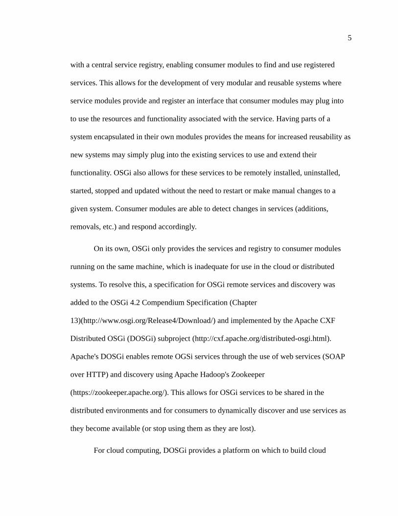
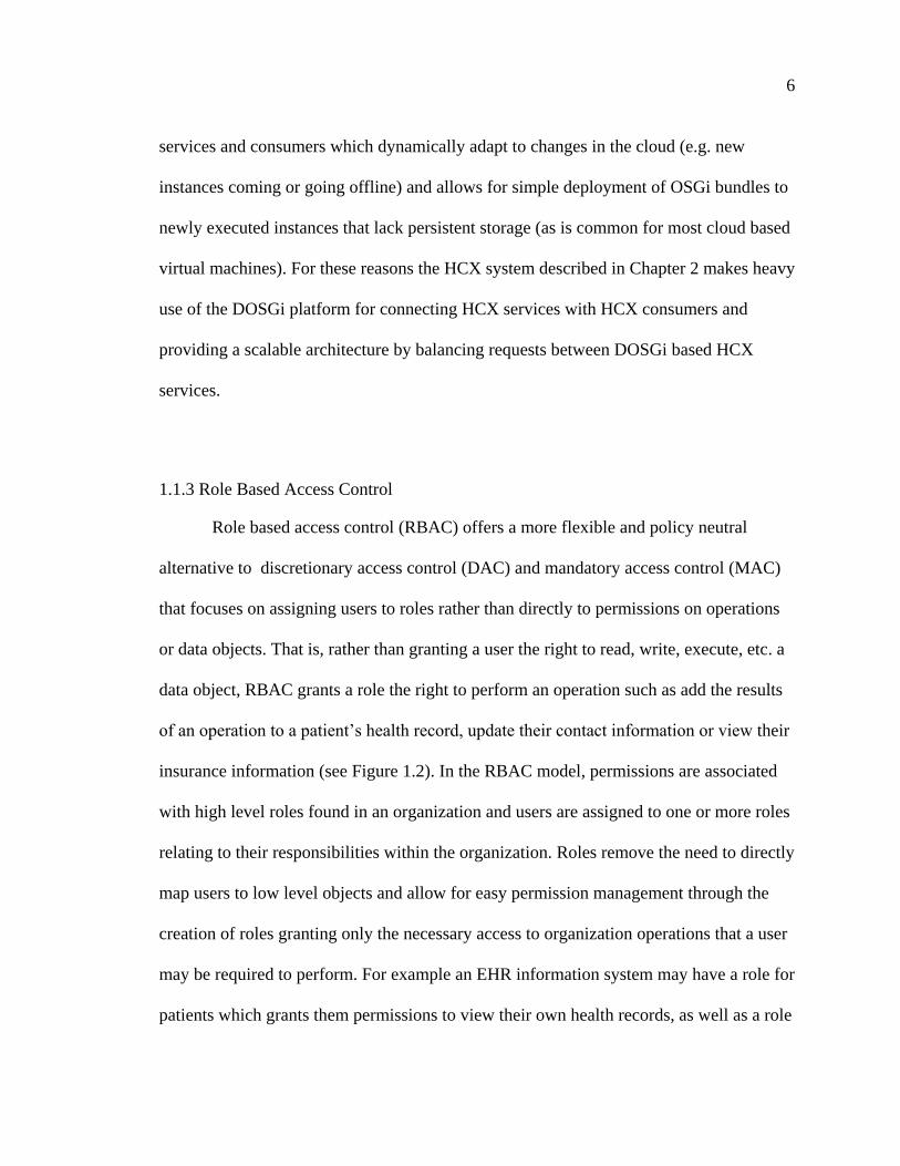
Role based access control (RBAC) offers a more flexible and policy neutral
alternative to discretionary access control (DAC) and mandatory access control (MAC)
that focuses on assigning users to roles rather than directly to permissions on operations
or data objects. That is, rather than granting a user the right to read, write, execute, etc. a
data object, RBAC grants a role the right to perform an operation such as add the results
of an operation to a patient’s health record, update their contact information or view their
insurance information (see Figure 1.2). In the RBAC model, permissions are associated
with high level roles found in an organization and users are assigned to one or more roles
relating to their responsibilities within the organization. Roles remove the need to directly
map users to low level objects and allow for easy permission management through the
creation of roles granting only the necessary access to organization operations that a user
may be required to perform. For example an EHR information system may have a role for
patients which grants them permissions to view their own health records, as well as a role
7
for doctors and health care professionals that grant them the ability to view and update
records for the patients under their care. This would be in direct contrast to the access
control list (ACL) model of access control which would have a user or group assigned
access rights to each individual data object (in this example a health record) rather than
enforcing a more abstract access control policy such as “patients can access an operation
to view their own health record” or “doctors can access an operation to view their
patients’ health records and an operation to update their patients’ health records”.
Figure 1.2: Basic RBAC model.
The RBAC model greatly simplifies the management of user permissions on large
systems and ensures that administrators can enforce the security principles of least
privilege and separation of duty/privilege (Saltzer & Schroeder, 1975) as they have a
very clear idea of the level of access a given user has by the roles they have been
assigned. RBAC also simplifies the problem of ensuring that users are given correct
access rights to a system. As users are assigned roles which map to permissions that in
turn map to abstract operations on an information system, an administrator would only
need to check that a user has been assigned the correct roles to ensure they have the
correct access rights (assuming the roles and permissions were created correctly).
Similarly, changing the level of access a role is given to match changes in organizational
8
policy or structure is trivial in RBAC as only the role-permission assignment would need
to be altered to affect the access rights of every user assigned to the role.
1.1.4 Identity and Attribute Based Cryptography
Identity based cryptography is a category of public key crypto systems where the
public key for a corresponding private key may be any publicly known string. This
allows for greatly simplified public key distribution as a user’s public key may be an
existing string associated with the user such as an e-mail address, physical address, or
host name. Most ID-based encryption schemes, such as that of Boneth and Fraklin
(2001), require a centralized trusted authority to act as a private key generator which
distributes private keys to users of the system. A more detailed and technical explanation
of identity based encryption is given in subsection 4.1.3 of Chapter 4.
Attribute Based Encryption (ABE) (first introduced by Sahai and Waters (2005))
builds on the concepts of ID-based encryption and allows a cipher text to be encrypted
such that only a user with a secret key containing the correct subset of attributes may
decrypt the document. More recent ABE schemes such as the Key Policy ABE (Goyal,
Pandey, Sahai, & Waters, 2006) and Cipher Text Policy ABE (Bethencourt, Sahai, &
Waters, 2007), allow for more complex attribute based access policies to be embedded in
the ciphertext or secret key. A more detailed and technical explanation of attribute based
encryption is given in Chapter 4 (particularly in subsection 4.1.3, 4.2.1, 4.2.2, and 4.2.3).
For the cloud, ABE offers the potential to have documents protected with an
access policy independent of the system holding them. Records encrypted with ABE are
protected both on and off the cloud with the same policy as well as both on and off line.
9
For the health care environment, such consistent protection that extends to records both
on and off line is critical when health services must be provided when access to EHR
systems may be unavailable (e.g. during a disaster which compromises online EHR
services) or in environments were a stable connection is not possible (e.g. remote areas).
1.2 The Cloud Problem
While cloud computing may offer potential cost savings and dynamically scalable
infrastructure, it also brings with it new security and privacy issues that need to be
addressed:
Confidentiality: Protecting cloud based storage and network transmissions from
possible unwanted access by cloud providers or data leakage to other cloud users.
Auditability: Maintaining logs of users’ actions with the system and ensuring that
no part of the system has been tampered with or compromised.
Security: Preventing user credentials, which may be used for multiple services on
and off the cloud, from being obtained by untrusted parties including the cloud
provider or other cloud users.
Legal: Complying with data privacy laws that may be in effect in given geographical
regions (eg. PIPEDA, HIPA, HIPAA, etc.).
Zhang, et al. list data security among one of the top open research problems in
cloud computing (Zhang, Cheng, & Boutaba, 2010) while Armbrust, et al. list data
10
confidentially and auditability among the top 10 obstacles for cloud computing
(Armbrust, et al., 2009) and for good reason; when utilizing a cloud based platform,
potentially sensitive information must be transmitted to, and stored on, a cloud provider’s
infrastructure. It is left to the cloud provider to properly secure their hardware
infrastructure and isolate customer’s processing and storage tasks. This transfer of trust
may be acceptable in most cloud use cases. However, in industries like healthcare that
must comply with data privacy laws such as PIPEDA, HIPA and HIPAA, allowing
sensitive information to be processed or stored on a public cloud directly may not be
feasible.
While many solutions for these issues exist for traditional systems, public cloud
infrastructure removes control of the physical infrastructure that makes it possible to
ensure a cloud provider properly secures their services and is not performing any
potentially malicious activities. It may seem unlikely that large public cloud operators
would intentionally violate their user’s privacy, but external factors in some regions (such
as legal pressure from local governments, e.g. USA PATRIOT Act) may force disclosure
of sensitive information. Hardware based solutions, such as Trusted Platform Module
(TPM), that would normally provide protection for a remote system, are difficult to
implement in cloud environments due to instances being created on a number of physical
servers that share the same hardware and lack of support from major cloud providers.
Additionally, cloud computing has several challenges related to taking full advantage of
the scalability gained from cloud infrastructure that limit potential solutions including:
11
Bottlenecks: The cloud may provide seemingly limitless scalability for virtual server
resources and storage, but any connections to systems outside of the cloud or lacking
the same scalability quickly become a new bottleneck for the system. For example, if
multiple machine instances are spawned to meet an increase in demand but all
connect to the same database or authentication backend provided by the same server,
a bottleneck will be formed that will limit the scalability of the whole system.
Distributed Design: While cloud computing is distinct from traditional distributed
computing, many of the same concepts apply and must be considered in the design of
a cloud application or platform. Cloud applications must be built to offer their
services from multiple machine instances distributed in the same cloud rather than a
traditional single server to client architecture.
Volatile Storage: Most cloud infrastructure solutions (such as Amazon’s EC2) do
not provide persistent storage by default to their machine instances. Applications
built upon such infrastructures need to take into account this static nature in their
design and use additional services or solutions (such as Amazon’s S3 or EBS) for
permanent storage.
Dynamic IPs: In most cases when cloud instances are launched, a public IP address
is dynamically assigned. While this may be selected from a list of static IP addresses,
autonomous cloud systems are often used which automatically create and destroy
instances, each obtaining an unused address when initialized. This can create issues
for traditional systems that expect static or unchanging addresses for servers.
12
There are still many legal questions regarding how cloud computing fits into, and
may comply with, the privacy laws present in most developed countries. Complicating
matters is the global nature of the cloud, a cloud provider may offer data centers in
multiple jurisdictions, while customers may be from another. In the European Union,
processing and security of personal data is mainly regulated by Directive 95/46/EC,
which outlines responsibilities of member states, data controllers (the one who
determines the means and processes of processing personal data) and data processors (the
one who processes personal data on behalf of the controller). In a cloud computing
environment it is not always straightforward which actor falls under which role (Balboni,
2010); cloud providers may have some level of control over the method in which data is
processed which would put them in more of a controller role than a pure processor role.
However, “regardless of whether the CSP [(cloud provider)] is to be considered a
Controller or a Processor, the customer will have to ensure that the CSP has appropriate
security measures in place” (Balboni, 2010). Under Directive 95/46/EC Article 17, this
requires implementing appropriate technical and organizational security measures to
protect personal data against accidental loss, alteration, unauthorised disclosure or access,
as well as any other form of unlawful processing. Article 17 also requires the controller to
choose a processor that provides sufficient guarantees with respect to the technical,
security, and organisational measures governing the processing to be carried out while
ensuring compliance with those measures.
In the United States of America data privacy falls under several acts, most notably
the Health Insurance Portability and Accountability Act (HIPAA) which regulates the use
and disclosure of identifiable health information by principal health care providers and
13
health plans. HIPAA requires that a covered entity must have a business associate
agreement (§§ 164.502(e), 164.504(e)) with the cloud provider and comply with the same
standards that apply to the entity. “A service provider cannot use or disclose health
records in a way that conflicts with the HIPAA standards. Thus, a HIPAA-covered entity
could violate HIPAA by storing patient records at a cloud provider with a terms of
service that allows the provider to publish any information stored on its facilities”
(Gellman, 2009). Additionally, many similar acts restrict the use of personal data in other
industries, including; the Gramm-Leach-Bliley Act (15 U.S.C. § 6802) which limits
financial institutions from disclosing financial information to third parties, the Video
Privacy Protection Act (18 U.S.C. § 2710) and Cable Communications Policy Act (47
U.S.C. § 551) that limit video rental records and cable television subscription records
from disclosure to third parties, tax preparation laws (e.g. 26 U.S.C. §§ 6713, 7216; 26
C.F.R. § 301.7216) which limit online tax preparers from sharing or storing personal
information (such as a social security number) with/on a foreign cloud without the
taxpayer’s consent, and federal agencies are prevented from disclosing personal
information to third parties such as cloud providers as it would likely violate the Privacy
Act of 1973 (U.S.C. § 552a) (Gellman, 2009). Furthermore, it is likely that the
Electronic Communications Privacy Act of 1986 (ECPA) provides some privacy
protection regulations for service providers (despite being originally drafted to give
protections against wiretapping telephone communications) and is further complicated by
the requirements set forth by the USA PATRIOT Act, requiring the FBI to have access to
any business record (including any record maintained by a cloud provider).
14
In Canada, standards for the private sector’s collection, use and disclosure of
personal information are established by the federal Personal Information Protection and
Electronic Documents Act (PIPEDA). Beyond giving individuals the right to request
details on what personal information relating to them an organization may have and how
it is used, the PIPEDA requires organizations to obtain consent when personal data is
collected, used or disclosed to a third party. This required consent would likely cause
issues when moving to the cloud unless prior consent was obtained from all parties or
steps were taken to ensure the data could not be accessed or disclosed to the cloud
provider. In addition to PIPEDA, four provincial privacy laws add provincial provisions
to protect personal information: An Act Respecting the Protection of Personal
Information in the Private Sector (Quebec), The Personal Information Protection Act
(Alberta), The Personal Information Protection Act (British Columbia) and The Personal
Health Information Protection Act (Ontario).
In Ontario the Personal Health Information Protection Act (PHIPA), requires that
a health information custodian (hospitals, doctors offices, etc.) and their agents (including
companies contracted for data storage and other IT tasks) comply with the custodian’s
information practices outlined in section 10(2) and “ensure that the records of personal
health information that it has in its custody or under its control are retained, transferred
and disposed of in a secure manner” (section 13 (1)). Additionally, information
custodians are made responsible for “tak[ing] steps that are reasonable in the
circumstance to ensure that personal health information in the custodian’s custody or
control is protected against theft, loss and unauthorized use of modification or disposal”
(section 12 (1)). This would seem to imply that in a cloud environment used for health
15
care, the consumer (acting as the health information custodian) and not the cloud provider
(acting as the custodian’s agent) would be made responsible for ensuring personal health
information on the cloud is properly secured and disposed of. If extra steps outside of the
services offered by the cloud provider are not taken, it is likely that meeting these
requirements would not be possible as the consumer has no way of ensuring true disposal
of electronic records or the security of the cloud provider’s data center or virtual
instances.
We categorize security on cloud based infrastructure into 6 levels, ranging from
totally unsecure but easy to implement and process data (level 0), to highly secure but
with a more complex implementation required (level 5):
Level 0: No encryption, authentication or security is used when
communicating with, processing data on, or storing data on cloud based
infrastructure.
Level 1: User authentication of some kind is required, however, no security or
encryption is required when communicating with the cloud application, storing
data on cloud based storage or processing data on cloud infrastructure.
Level 2: Same requirements as level 1 but a secure channel is required for
communications between the cloud based application and the user (e.g. SSL).
Level 3: Same requirements as level 2 but all data stored on the cloud must be
securely encrypted (e.g. encrypting data on S3 with AES encryption).
Level 4: Same requirements as level 3 but no unencrypted sensitive data
should be handled by any part of the system exposed to the cloud provider (i.e.
the cloud application/instances should not have access to the encryption keys
16
used to decrypt data stored on cloud based storage and no raw sensitive data
should be processed by the application or cloud providers network).
Level 5: Same requirements as level 4 but it should be impossible for the cloud
provider to identify the user of the system beyond an IP address and
anonymized user ID. (i.e. the cloud provider should be unable to determine any
potentially sensitive or identity revealing information about the user of the
system).
In most cases level 2 or 3 is enough to satisfy the requirements set forth by data
privacy laws and protect against an eavesdropper not associated with the cloud provider.
However, in cases where the cloud may not be trustworthy or could potentially become
compromised, a level of 4 or higher would be required to fully protect sensitive
information from an attacker with access to the cloud provider’s hardware and datacenter
resources. Level 5 is required to ensure both the privacy and confidentiality of the data
as well as some level of anonymity for the users of the system. This may be critical for
applications such as patient portals which enable patients to view and possibly modify
their health records and related medical information online.
1.3 Cloud Security Approaches and Techniques
While the problem of cloud security and confidentiality in a public cloud is still
largely open (Zhang, Cheng, & Boutaba, 2010), several efforts have put forth approaches
and techniques to either minimize the issue (Pearson, Shen, & Mowbray, 2009) or used
hardware based solutions (Itani, Kayssi, & Chehab, 2009), (Chow, et al., 2009) to regain
17
some level of control from cloud providers. To our knowledge, there is still no purely
software based solution for providing complete confidentiality of data stored on a public
cloud from a potentially untrustworthy cloud provider that remains scalable, distributed
and practical in a cloud based environment. The traditional and somewhat trivial solution
amounting to “throwing encryption at the problem” (commonly suggested as a potential
solution (Armbrust, et al., 2009)) falls short for standard symmetric encryption methods.
While sensitive data on cloud based storage may be encrypted, it may not be processed
by the same provider (e.g. to serve to clients via a web based interface) without
relinquishing the keys required to decrypt or access the data. Similarly, access policies
enforced by cloud based systems are vulnerable to compromised or untrustworthy cloud
providers as they ultimately control the hardware, network and virtualization resources.
1.3.1 Privacy as a Service: Privacy-Aware Data Storage and Processing in Cloud
Computing Architectures (Itani, Kayssi, & Chehab, 2009)
1.3.1.1 Summary
Itanit, et al. (2009) presents a set of security protocols, named PaaS (Privacy as a
Service), for providing privacy and security of user’s data in the cloud through the use of
cryptographic coprocessors. Their solution allows users to configure software and data
privacy mechanisms which dictate how their data will be protected in the cloud as well as
provide feedback on any potential risk that may affect the confidentiality and security of
their sensitive information.
Cryptographic coprocessors (Best, 1980) (Tygar & Yee, 1994) are isolated
“computer on a chip” systems dedicated to performing cryptographic operations separate
18
from the computer hardware/system they are installed in. Most coprocessors take the
form of small PCI-based hardware cards which contain an independent and complete
computing system including separate RAM, processor, networking adaptor and non-
volatile storage. The key feature that makes such coprocessors different from common
computing systems is a specialized tamper-resistant encasing that provides several
physical security measures against physical attacks (e.g. manually extracting data from
the non-volatile storage). These security measures commonly include automated
“zeroization” (overwriting memory with zeros such that it cannot be recovered) of
volatile and non-volatile storage, tamper-detection/reporting, and authentication of both
the software and operating system before loading/booting.
Itanit, et al. (2009) suggests that a trusted (to both cloud users and providers) third
party organization could configure, install, inspect, and distribute secure cryptographic
coprocessors to cloud providers. This trusted third party (TTP) would configure each
coprocessor such that it could be shared among multiple virtualized systems (as a single
coprocessor for each virtualized machine instance would quickly become
unmaintainable) and load the private/public key pairs (PUCID/PRCID) into the non-volatile
storage of each coprocessor as well as its own private key (KTTP). The TTP would then
become primarily responsible for allocating each key pair to a single customer as
requested and updating/replacing key pairs as necessary (this is possible through the use
of the private key KTTP to authenticate as the TTP with each coprocessor).
Cloud users are made responsible for configuring their software application to
support the coprocessor model by dividing their application into the logical components
of protected and unprotected. Protected components are executed within the coprocessor
19
while unprotected components are executed in the standard virtualized environment.
Protected components are encrypted with the customers credentials (based on
PUCID/PRCID) and stored on the cloud provider’s storage until executed on a coprocessor.
Data is secured based on one of three classifications; No Privacy: data is not encrypted
and no effort is made to protect it beyond possible transmission via SSL, Privacy with
Trusted Provider: data is encrypted with a key potentially known to the cloud provider
and is transmitted and stored in an encrypted state, and Privacy with Non-Trusted
Provider: data is encrypted using a secret key (KCID) shared only with the coprocessor
(shared by authenticating with coprocessor and starting a secure session with
PUCID/PRCID) and uploaded to standard cloud storage in the encrypted state (which may
be accessed only by protected parts of the application on the coprocessor using KCID).
Privacy feedback is provided through the use of a daemon executed on the same
coprocessor as protected application components which keeps a detailed encrypted (with
KCID) audit log of all privacy-related operations (e.g. execution of application
components, decryption of “Privacy with Non-Trusted Provider” data, etc.). A hash chain
of the encrypted audit log (Schneier & Kelsey, 1999) (Itani, Kayssi, & Chehab, 2005) is
then created by hashing the ith
record (HCi) and the chain entry of the last record (HCi-1),
making it possible to authenticate the integrity of all previous records simply by
authenticating HCi. The audit log and chain are made available to the cloud user via a
special application which polls and verifies the contents of the log periodically at set
intervals.
20
1.3.1.2 Criticisms
While Itanit, et al. (2009) present an effective means of securing cloud
applications and data using cryptographic coprocessors, they ignore the realities of
current cloud offerings and assume a rather optimistic view of the financial and technical
feasibility of incorporating large numbers of coprocessors in cloud infrastructure and
services. The largest issue is the lack of support for any kind of tamper- proof
coprocessor in the current cloud offerings. To date there are currently no cloud providers
which offer cryptographic coprocessors hardware or services that the PaaS protocol
requires. Additionally, there is little if any financial incentive for cloud providers to add
coprocessors hardware to their existing data center infrastructure and even less incentive
to give full access to their data centers to a third party for the required periodic
inspection, installation and maintenance of coprocessors.
Another issue with Itanit, et al. (2009)’s PaaS is moving a large part of a cloud
application’s execution from scalable cloud infrastructure to limited coprocessors
execution. Most modern coprocessors provide only limited processing, RAM and
persistent storage resources. However, large cloud application serving sensitive
information to clients (such as banking or EHR systems) will require heavy use of the
coprocessor to encrypt/decrypt data and transmit/receive it to/from clients. While the
PaaS system allows for a single coprocessor to be shared by multiple virtual systems,
sharing may not be technically feasible if applications make anything but occasional use
of protected components.
The sharing of coprocessors presents a potential point of attack against a cloud
application when a malicious user is sharing the same resources. Unlike cloud processing
21
and storage resources which are strictly isolated, resources on a shared coprocessor
would be accessible to all users on the system. While most sensitive data would be
protected with each user’s individual secret key (KCID) and applications isolated using the
ABYSS processor model (White & Comerford, 1990) a malicious user could still stage a
denial-of-service type attack by having their protected applications use as much
processing, network, storage and memory resources as possible to slow or even stop the
execution of other protected applications sharing the same coprocessor.
Finally, the heavy use of a trusted third party by PaaS simply shifts the control
from a cloud provider to the party managing and maintain the coprocessors. Since a third
party would have full control over each coprocessor they would easily be able to extract
the value of KCID from memory and decrypt sensitive data or simply extract the data as it
is being processed. It may be hard to find a party that could be realistically trusted more
than a cloud provider to perform this role.
1.3.2 A Privacy Manager for Cloud Computing (Pearson, Shen, & Mowbray, 2009)
1.3.2.1 Summary
S. Pearson, et al. (2009) introduces a privacy manager for cloud computing aimed
at reducing the potential risk of sensitive data being stolen or misused on the cloud. The
privacy manager obfuscates sensitive data for storage on the cloud and performs de-
obfuscation as needed when data is requested. This obfuscation is performed by
encrypting the data with a key chosen by the cloud user which is shared with the privacy
manger but not the cloud provider. The obfuscation is based on a process where for some
22
plain text x a cloud application may only compute f(x) for some function f when given the
cipher text but not the value of x itself.
This obfuscation is accomplished as follows: A key k and encryption functions o1,
.., om are picked (for some positive value of m) such that it is hard to determine x from the
tuple o1(k,x), .. om(k,x) without k and that there is a decryption function d such that d(k,
f1(o1(k,x)),…, fm(om(k,x))) = f(x) were f is the function for the desired calculation on x and
f1 to fm are calculations done by the application. Obfuscation is accomplished by first
encrypting x with each encryption function and a secret key k to produce o1(k,x), ..
om(k,x). This tuple is then sent to the cloud application which computes the values
f1(o1(k,x)),…, fm(om(k,x)) and sends them back to the client. The client may then use the
decryption function d and key k to obtain the result of the function f, f(x).
Examples are given of how to apply this method to obfuscating patient names in
health records (by having m=1, k being the map of patient IDs to pseudonyms o1 being
the application of k and d the inverse map), obfuscating SQL queries and several other
use cases.
1.3.2.2 Criticisms
The main issue with the obfuscation method proposed by S. Pearson, et al. (2009)
is that it only works for trust-worthy cloud providers who are unlikely to put the effort in
to de-anonymizing or de-obfuscating records. For example, in the use case of health
records presented where patient names are replaced with pseudonyms, it would be
somewhat trivial for a malicious or compromised cloud provider to de-anonymize records
by comparing the contents of the EHR to publicly available information. This could be
23
done by cross referencing emergency contact phone numbers with a phone book or
narrowing down owners of a given record by age, past conditions/ailments, and location
(from an address, or postal code). At a minimum, a k-Anonymity (Sweeney, 2002) type
approach would be required to properly anonymize sensitive information.
Secondly, this approach only deals with the case where a client of a cloud
application needs to send sensitive data to the application and receive the result of some
computation. As the data is encrypted with a key known only to the client, the encrypted
data is isolated to only that client and may not be shared or stored in a meaningful or
unanonymized form. Similarly, this approach may not be used to share secured sensitive
information stored on cloud storage as clients of the application would lack access to the
key used to obfuscate the data.
1.3.3 Towards Trusted Cloud Computing (Santos, Gummadi, & Rodrigues, 2009)
1.3.3.1 Summary
Santos, et al. (2009) proposes a design for a Trusted Cloud Computing Platform
(TCCP) which enables cloud providers to guarantee confidential execution of cloud user
provided virtual machines. Santos, et al. (2009) extends the idea of the trusted platform
module (TPM) to the cloud to prevent tampering with a virtualized machine instances
memory. TPMs are a type of cryptographic coprocessor proposed by the Trusted
Computing Group (http://www.trustedcomputinggroup.org/) with the ability to provide
“remote attestation” that a system is running a specified software package as its operating
system, BIOS, bootloader, etc. at boot time. This is accomplished as follows: initially
every TPM is assigned a public/private key pair by the manufacture for which the public
24
key is publicly known and verifiable. At boot time the TPM creates a measurement list
containing hashes of all software involved in the boot sequence of the system, which is
stored in the protected storage of the TPM. Once booted, a remote entity may request
attestation of the boot software by challenging the system with a random nonce, for
which the system must reply with the measurement list and nonce encrypted with the
TPM’s private key. The remote system may then verify that the measurement list was
sent by the TPM by decrypting the message with the TPM’s public key.
While this method serves to verify the boot sequence of server, it is not enough on
its own to secure the virtual machines executed upon it as a system administrator may
make changes to the system after the boot sequence, migrate the virtual machine, or
simply not run the virtual machine on a system protected by a TPM. To solve these
issues, Santos, et al. (2009) have created the TCCP which consists of a trusted virtual
machine monitor (TVMM) and trusted coordinator (TC). The TVMM consists of a host
operating system for executing guest virtual machines which prevents privileged users
from alerting or inspecting the state of running machine instances. The TVMM is
installed on the cloud providers nodes equipped with a TPM module capable of proving
attestation to the boot sequence. A trusted third party is required to run and maintain the
TC which manages the nodes running the TVMM, recoding their TPM’s public key
(EKpub
n) and expected measurement list (MLn) while publicly publishing its own TPM’s
public key (EKpub
tc), expected measurement list (MLtc), and trust key (TKpub
tc).
Node registration occurs when a node is booted and proceeds with both the node
and TC requesting attestation of the others boot sequence and the node generating a new
public/private key pair (TKpub
n / TKprv
n) of which the public key is sent to the TC and
25
registered, certifying that the node is trusted. To ensure the security of the system, TKprv
n
is to only be stored in memory on the node so that it may not be extracted from the
node’s hard drive when offline. Upon each reboot, the registration sequence is repeated
and a new TKpub
n / TKprv
n pair is generated.
To guarantee that a virtual machine is launched on a trusted node and that a
system administrator is unable to alter its contents, TCCP requires the following protocol
for registering and running a virtual machine. When a cloud user wishes to register a
virtual machine image (a), they first compute a hash of the image (a#) and generate a
session key (Kvm). They then proceed by encrypting a and a# with Kvm ({a, a#} Kvm) and
encrypting a random nonce (n) and Kvm with TKPub
TC ({n, Kvm}TKPub
TC)and sending both
to the cloud provider. The cloud provider may then store both ciphertexts for use when
the user wishes to execute the image on the cloud. When the user gives such an order, the
ciphertexts are sent to the trusted node on which the image is to be executed and the node
requests Kvm from the TC by sending it the ciphertext {n, Kvm}TKPub
TC, and a random
nonce (nn) encrypted with TKprv
n and appended with the nodes ID and further encrypted
with TKPub
TC. If the request is valid (i.e. the TC is able to decrypt the cipertext containing
nn and {n, Kvm}TKPub
TC using TKpub
n) it responds to the node with the values of nn, n, and
Kvm (which it decrypted using TKprv
TC) encrypted with TKpub
n . Finally the node is able to
decrypt the value of Kvm using TKprv
n and use Kvm to decrypt the machine image and hash,
a and a#, and run the instance. Santos, et al. (2009)’s TCCP also provides similar
methods for securing live virtual machine migration and protecting both the machine’s
state and image from inspection or alteration by a system administrator during migration.
26
1.3.3.2 Criticisms
Like Itanit, et al. (2009)’s PaaS approach (see section 1.3.1), Santos, et al.
(2009)’s TCCP is dependent on the presence and support of an additional hardware
component (in this case a TPM) that is not currently offered by any cloud provider. This
brings with it similar issues resulting from lack of support making it impossible to use at
the current time. However, unlike PaaS, TCCP does not have the same scalability and
sharing risks as only a single TPM is needed and is only used by each node directly
(rather than by the cloud user directly). Also, like Itanit, et al. (2009)’s approach, Santos,
et al. (2009)’s method is dependent on a trusted third party taking control of some part of
the cloud provider’s process/system. However, rather than simply shifting control to the
third party, TCCP properly divides trust between the cloud provider and third party such
that in theory, they would both need to be colluding to compromise the system.
One large issue with TCCP is that it is built on the assumption that a malicious
system administrator would not have access to the hardware components in a trusted
node. If the administrator had such access, or the whole cloud provider was
untrustworthy, there are several avenues of attack they could attempt. With the proper
tools, sophisticated attacks are possible to read the contents of RAM in an active system
with only access to the hardware (Samyde, Skorobogatov, Anderson, & Quisquater,
2003) and possibly more concerning “cold boot” attacks are possible against most types
of RAM for a few seconds after power is lost where data may be extracted even at room
temperature and without special tools (Halderman, et al., 2009). If a malicious
administrator or cloud provider were able to extract TKprv
n from the RAM of a node they
would be able to fake a trusted node and compromise the security of the whole system.
27
Furthermore, if a decrypted copy of the virtual machine image is being stored on a node’s
hard drive even temporarily it may be possible for an attacker to extract sensitive
information either by powering off the node while the virtual machine is active and
extracting the information from the hard drive or setting up a hot swappable disk in a
RAID 1 setup such that the main disk is mirrored to a second disk and may be removed
while the machine instance is active and read without disrupting service.
1.5 Towards Cloud Security and Privacy for Sharing EHRs
While the current hardware approaches for cloud security and confidentiality
(Itani, Kayssi, & Chehab, 2009) (Santos, Gummadi, & Rodrigues, 2009) are promising,
they rely on hardware components and support by cloud providers that is currently not
offered nor necessarily desired (there is little incentive for cloud providers to install
potentially expressive cryptologic coprocessors and hand over control to a third party).
Current software and encryption based solutions (Pearson, Shen, & Mowbray, 2009) only
offer partial security (e.g. data obfuscation or anonymization) and rely on a partially
trusted cloud provider (at least one that will not extract encryption keys from a running
virtualized machine instance). The approach presented in this thesis aims to overcome the
limitations of a hardware based approach (i.e. requiring support from the cloud provider
and investment in new cloud hardware infrastructure) and provide full protection of data
both on and off the cloud (including cases were no internet or network access is possible).
The research put forth is a step forward towards creating a system for ensuring
cloud security with the ultimate goal of securing an untrusted public cloud to the point
28
where it may be used for health care applications such as storing and processing EHRs.
Such protections in a cloud environment require that several design objectives be met in a
secure and reasonably efficient way:
Regulatory Compliance: A system that wishes to deal with EHRs of real
penitent’s personal and potentially sensitive information must often meet with
strict local laws governing the use, transmission and storage of personal health
information. In most cases this requires that at a minimum unanonymized records
be encrypted and protected from view by any unauthorized third party including
the cloud provider (for a more detailed description of laws applying to EHRs see
section 1.2).
Comprehensive Security: Sensitive data stored in the cloud needs to be protected
at all points in its use. This includes enforcing access policies during storage on
the cloud, processing in the cloud, transmission to, from and within the cloud and
off the cloud where users may store or transmit copies locally. The access policy
under which records are secured needs to be independent of the system on which
they are stored and processed and consistent on all systems to which it may be
transmitted.
Confidentiality: Both records and information on the system’s users should be
isolated from outside entities (e.g. the cloud provider) as much as possible to
avoid both the leakage of private information and the potential of an attacker
compromising user accounts. User credentials and authentication must be isolated
from the public cloud to avoid possible exploitation by a malicious cloud provider
or cloud system administrator (e.g. a malicious entity with control of an
29
authentication system on a public cloud may be able obtain user credentials from
the memory or storage of the virtual machine instance).
Role Based Access Policies: To provide simple administration of users and
protection of resources that models the real life policies of organizations, a role
based access control system is required. At a minimum, such a system should
allow for the creation of roles that may be mapped to a set of permissions that
dictate access to system resources. Similarly, users should be mapped to roles
related to their real life roles in an organization to enable system access.
Distributed: The nature of the cloud (i.e. multiple virtualized machine instances
which may be spawned and destroyed dynamically) requires a distributed model
to ensure scalability and reliability. However, more importantly, administration
and control of the system must be distributed in many scenarios. For example in
the case of sharing EHRs on the cloud, multiple organisations (e.g. hospitals,
doctor’s offices, labs, etc.) will have their own sets of users, administrators and
access policies which need to be supported and independent of other parties while
still enabling sharing when appropriate.
Scalable: One of the main advantages of cloud computing is its ability to be
dynamically scaled to meet changes in demand. In many cases this is
accomplished by spawning new virtual machine instances containing system
components as demand increases and destroying them as demand returns to
normal. A system for the cloud needs to be scalable in the same way, which is,
simply by adding more nodes. This requires at least linear scalability in the
majority of the system to be effective.
30
These objectives are accomplished with a variety of techniques including attribute based
encryption (to accomplish legal compliance, confidentiality of encrypted records, and
comprehensive enforcement of access policies), a DOSGi based framework (to provide
dynamic discovery and communication between EHR services such that they may be
properly scaled in a distributed environment), a role based access policy model (to enable
role based access policies on records and services) and a single sign-on protocol (to allow
for distributed access control and the confidentiality of user credentials).
1.6 Thesis Layout
This thesis presents four major components which, when combined, create a
novel system for securing a potentially untrustworthy public cloud to store and distribute
health records. These components include the Health Cloud eXchange (HCX)
architecture, the Role Based Access Control as a Service (RBACaaS) model and access
control system, the Role Based Single Sign-On (RBSSO) protocol and the Distributed
Multi-Authority Ciphertext-Policy Shared Attribute-Based Encryption (DMACPSABE)
scheme. The HCX architecture (presented in Chapter 2) provides a distributed OSGi
(DOSGi) based architecture for storing and sharing EHRs over a public, private or
federated cloud. The RBACaaS model and access control system (presented in Chapter
3) provides a model, service implementation and administration interface for providing
role based access control to cloud applications and platforms via webserver or DOSGi
calls. The RBSSO protocol (also presented in Chapter 3) provides a light weight and
31
scalable single sign-on protocol for cloud based applications with support for the
RBACaaS RBAC model/system and DMACPABE based encryption policies. Finally, the
DMACPSABE encryption scheme (presented in Chapter 4) provides extensions to the
Ciphertext-Policy Attribute-Based Encryption model proposed by Benthencourt, et al.
(2006) to add multiple distributed authorities which share a subset of attributes without
the need for a user to communicate with more than one authority (or any need for inter
authority communication). Additionally, a “not equals” operation and authority hierarchy
is incorporated.
This thesis is divided into five chapters including this introduction and
conclusion. Chapters two, three and four contain an introduction to the subject area
covered by the chapter, background information, a review of current and relevant
research in the area, and the presentation of at least one of the novel components which
comprise our solution. Chapter five details how these components may be combined to
produce a full solution to cloud security, discussion of our results, discussion of further
work needed in this area and concluding remarks. Chapter summaries are given in Table
1.1.
Chapter Summary/Contents
1. Introduction Introduction of “the cloud problem”, background information,
current approaches to cloud security, research goals and thesis
layout.
2. Constructing A
Cloud Based
Infrastructure for
Sharing Health Records
(HCX)
Review of existing EHR standards, presentation of the DOSGi
based HCX architecture for sharing health records and
implementation details for a cloud based environment.
3. Developing a Cloud
Based Role Based
Access Control and
Review of existing RBAC models, presentation of the
RBACaaS model and access control system, review of existing
single sign on protocols, presentation of the RBSSO protocol,
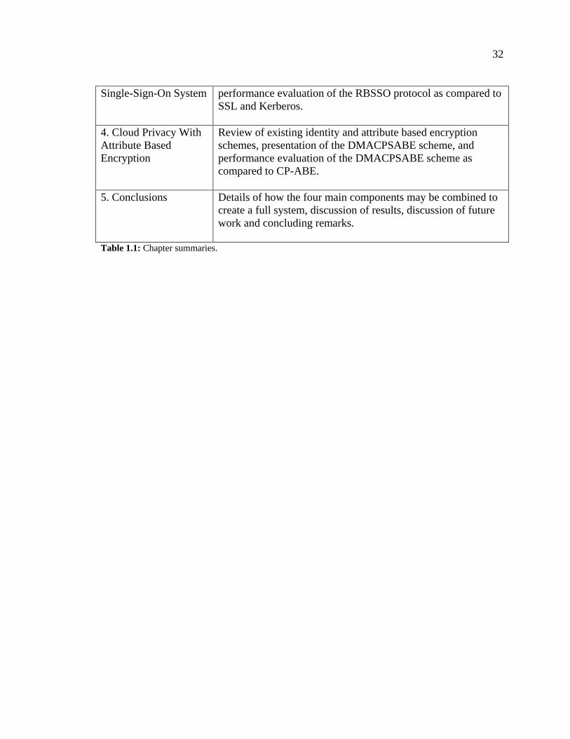
32
Single-Sign-On System performance evaluation of the RBSSO protocol as compared to
SSL and Kerberos.
4. Cloud Privacy With
Attribute Based
Encryption
Review of existing identity and attribute based encryption
schemes, presentation of the DMACPSABE scheme, and
performance evaluation of the DMACPSABE scheme as
compared to CP-ABE.
5. Conclusions Details of how the four main components may be combined to
create a full system, discussion of results, discussion of future
work and concluding remarks.
Table 1.1: Chapter summaries.
33
33
Chapter 2
2 Constructing A Cloud Based Infrastructure
for Sharing Health Records (HCX)
2.1 EHR Specifications
There are many notable EHR standards for storing, processing and transmitting
patient healthcare records such as HL7 CDA (DOLIN, ALSCHULER, BOYER, &
BEEBE, 2006), Continuity of Care Record (CCR) (ASTM International, 2005), HL7
Continuity of Care Document (CCD) (Health Level Seven International, 2007), DICOM
(ftp://medical.nema.org/medical/dicom/2011/) and openEHR(http://www.openehr.org).
The CCR and CCD standards have gained wide acceptance in the healthcare community
due in part to the support provided by major EHR vendors including Google (via Google
Health), and Microsoft (via Microsoft’s HealthVault(http://www.microsoft.com/en-
us/healthvault/)). With the growing number of EHR platforms, interoperability is
becoming a major issue which the CCR and CCD standards seek to solve through a
patient health summary which contains the most commonly used and required
information used and stored by EHR systems.
2.1.1 Continuity of Care Record
The Continuity of Care Record (CCR) is an XML based patient health summary
containing the “most relevant administrative, demographic, and clinical information facts
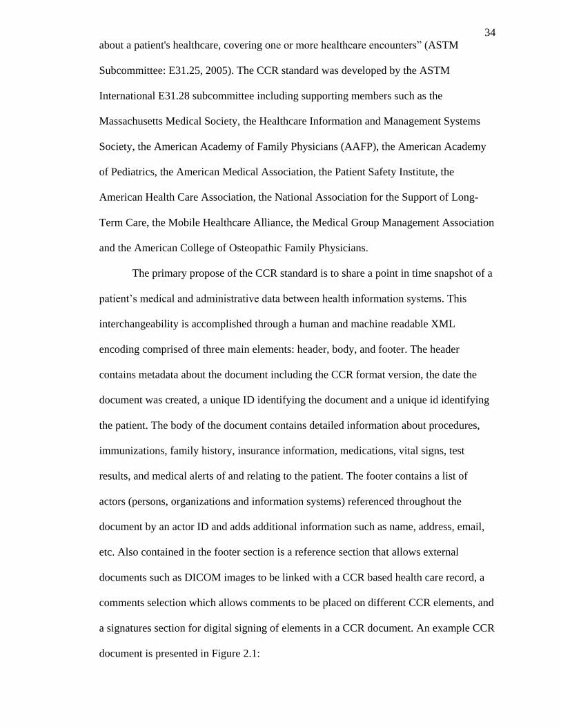
34
about a patient's healthcare, covering one or more healthcare encounters” (ASTM
Subcommittee: E31.25, 2005). The CCR standard was developed by the ASTM
International E31.28 subcommittee including supporting members such as the
Massachusetts Medical Society, the Healthcare Information and Management Systems
Society, the American Academy of Family Physicians (AAFP), the American Academy
of Pediatrics, the American Medical Association, the Patient Safety Institute, the
American Health Care Association, the National Association for the Support of Long-
Term Care, the Mobile Healthcare Alliance, the Medical Group Management Association
and the American College of Osteopathic Family Physicians.
The primary propose of the CCR standard is to share a point in time snapshot of a
patient’s medical and administrative data between health information systems. This
interchangeability is accomplished through a human and machine readable XML
encoding comprised of three main elements: header, body, and footer. The header
contains metadata about the document including the CCR format version, the date the
document was created, a unique ID identifying the document and a unique id identifying
the patient. The body of the document contains detailed information about procedures,
immunizations, family history, insurance information, medications, vital signs, test
results, and medical alerts of and relating to the patient. The footer contains a list of
actors (persons, organizations and information systems) referenced throughout the
document by an actor ID and adds additional information such as name, address, email,
etc. Also contained in the footer section is a reference section that allows external
documents such as DICOM images to be linked with a CCR based health care record, a
comments selection which allows comments to be placed on different CCR elements, and
a signatures section for digital signing of elements in a CCR document. An example CCR
document is presented in Figure 2.1:
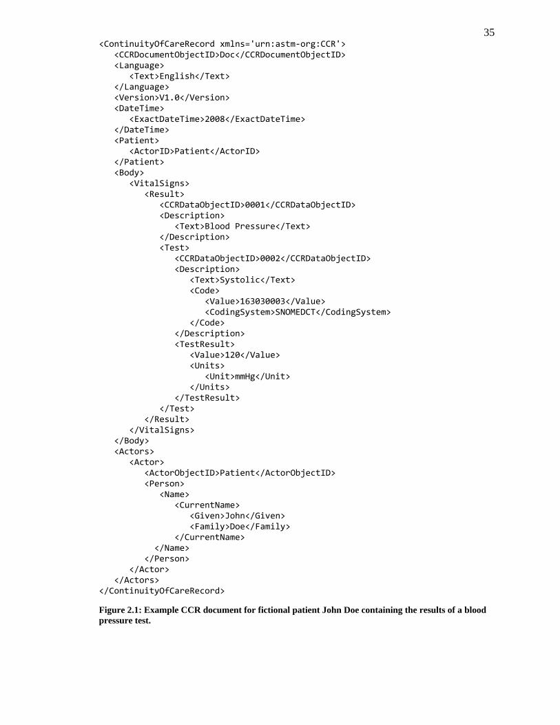
35 <ContinuityOfCareRecord xmlns='urn:astm-org:CCR'> <CCRDocumentObjectID>Doc</CCRDocumentObjectID> <Language> <Text>English</Text> </Language> <Version>V1.0</Version> <DateTime> <ExactDateTime>2008</ExactDateTime> </DateTime> <Patient> <ActorID>Patient</ActorID> </Patient> <Body> <VitalSigns> <Result> <CCRDataObjectID>0001</CCRDataObjectID> <Description> <Text>Blood Pressure</Text> </Description> <Test> <CCRDataObjectID>0002</CCRDataObjectID> <Description> <Text>Systolic</Text> <Code> <Value>163030003</Value> <CodingSystem>SNOMEDCT</CodingSystem> </Code> </Description> <TestResult> <Value>120</Value> <Units> <Unit>mmHg</Unit> </Units> </TestResult> </Test> </Result> </VitalSigns> </Body> <Actors> <Actor> <ActorObjectID>Patient</ActorObjectID> <Person> <Name> <CurrentName> <Given>John</Given> <Family>Doe</Family> </CurrentName> </Name> </Person> </Actor> </Actors> </ContinuityOfCareRecord>
Figure 2.1: Example CCR document for fictional patient John Doe containing the results of a blood
pressure test.
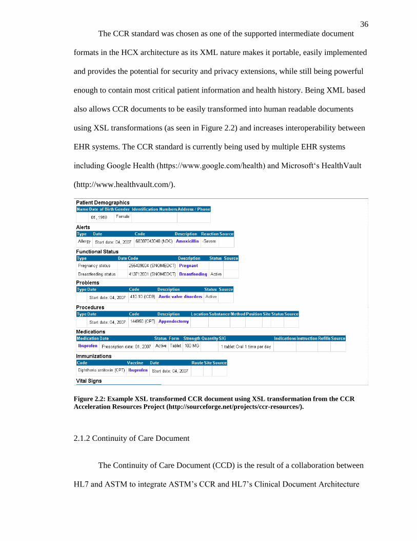
36
The CCR standard was chosen as one of the supported intermediate document
formats in the HCX architecture as its XML nature makes it portable, easily implemented
and provides the potential for security and privacy extensions, while still being powerful
enough to contain most critical patient information and health history. Being XML based
also allows CCR documents to be easily transformed into human readable documents
using XSL transformations (as seen in Figure 2.2) and increases interoperability between
EHR systems. The CCR standard is currently being used by multiple EHR systems
including Google Health (https://www.google.com/health) and Microsoft‘s HealthVault
(http://www.healthvault.com/).
Figure 2.2: Example XSL transformed CCR document using XSL transformation from the CCR
Acceleration Resources Project (http://sourceforge.net/projects/ccr-resources/).
2.1.2 Continuity of Care Document
The Continuity of Care Document (CCD) is the result of a collaboration between
HL7 and ASTM to integrate ASTM’s CCR and HL7’s Clinical Document Architecture
37
(CDA). The CCD specification, much like the CCR specification, describes a XML based
patient health summary which contains the most critical and commonly needed patient
medical and administrative information by modern EHR systems. Also akin to the CCR
specification, the XML nature of the CCD specification allows for easy implementation,
readability (by both humans and parsers) and interoperability between EHR systems.
However, the CCD format has several advantages over the CCR document including
supporting additional clinical documents outside of the patient summary (such as
Discharge Summary which is out of the scope of the CCR document), enhancements for
easy rendering and human readability, support of the Reference Information Model
(RIM), and greater acceptance including acceptance on the national level in countries
such as Canada, France, Greece, Finland, England, and Argentina as well as efforts in the
United States.
The CCD specification was chosen in addition to the CCR specification to
increase compatibility with existing EHR systems and to take advantage of the support of
additional clinical documents lacking in the CCR format. The XML nature of both
formats maintains portability and interoperability while also providing a human readable
that match well as an intermediate format for the goals of the HCX Architecture.
2.1.3 Others
There are multiple EHR specifications and formats in existence and used today
including HL7 CDA, openEHR, and e-MS Electronic Medical Summary for which
details have been omitted for space and complexity reasons. The CCR format is an ideal
use case for the research presented as it is simple, human readable, used by existing cloud
PHR systems and an open standard. However, in general, if the record can be stored,
transmitted and encrypted it may be used with the techniques introduced in the described
38
systems, models and schemes. In a real world implementation of the systems described in
this thesis, it is likely that some standardization in the EHRs shared would be required,
but, for simplicity sake it is assumed that the only standards being used are CCR and
CCD.
2.2 HCX Architecture
In this section we describe our Health Cloud eXchange (HCX) architecture for
both sharing and storing EHRs over a public, private or federated cloud. HCX can act
both as the middleware between existing EHR systems as well as an independent cloud
based EHR management and storage system with the possibility of web and application
based patient portals. Our architecture aims to accomplish the following goals in addition
to providing cloud base EHR services:
1. Modularity: To accommodate the changing nature of the cloud, with machine
instances being created and destroyed based on demand, the system should be
able to automatically adapt to HCX services coming and going off line. Also, the
consumers should be able to automatically discover and use any HCX service that
implements a standard interface.
2. Interoperability: HCX should function both as an independent EHR system and
as the middleware between existing EHR systems on and off the cloud. This
should be accomplished with minimal changes to existing systems through the
adoption of widely supported standards such as CCD and CCR.
3. Loosely Coupled: Service consumers should be able to use any HCX service
implementation assuming it follows a standard interface. From a consumer’s
stand point, services acting as a middleware between systems should be identical
39
to those serving records directly from the HCX system (i.e. from a cloud based
EHR repository).
4. Simplicity: The HCX architecture and service interface should be as easy to
implement as possible to allow for new HCX services and clients to be rapidly
created that connect existing EHR systems with little effort from developers.
5. Leverage Cloud Infrastructure: The system should take advantage of the
dynamic scalability of the cloud and automatically adapt to creation and
destruction on machine instances that contain HCX services.
6. Distributed: The system should be as distributed, with few centralized points of
failure. The failing of a single or multiple HCX services should have no effect on
consumers beyond making their records temporarily unavailable.
7. Extendibility: The HCX architecture should be extendable so that custom or third
party authentication, administration, and security modules may be used in
implementing systems. Note that HCX itself does not deal with security,
authentication or confidentiality and that these issues are dealt with in the
proceeding chapters (namely Chapters 3 and 4).
2.2.1 Services
The proposed HCX architecture provides several primitive service interfaces:
EHRProvider , EHRManager, EHRPortal, Administative and AuditLog. Any number of
services implementing these interfaces may run within the same cloud and are registered
upon execution with a central service registry for dynamic service discovery. Multiple
instances of the same service may be run simultaneously, balancing the load between
them (in cases where they provide the same services or records) and creating a shared
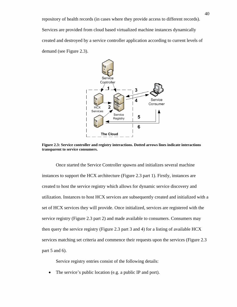
40
repository of health records (in cases where they provide access to different records).
Services are provided from cloud based virtualized machine instances dynamically
created and destroyed by a service controller application according to current levels of
demand (see Figure 2.3).
Figure 2.3: Service controller and registry interactions. Dotted arrows lines indicate interactions
transparent to service consumers.
Once started the Service Controller spawns and initializes several machine
instances to support the HCX architecture (Figure 2.3 part 1). Firstly, instances are
created to host the service registry which allows for dynamic service discovery and
utilization. Instances to host HCX services are subsequently created and initialized with a
set of HCX services they will provide. Once initialized, services are registered with the
service registry (Figure 2.3 part 2) and made available to consumers. Consumers may
then query the service registry (Figure 2.3 part 3 and 4) for a listing of available HCX
services matching set criteria and commence their requests upon the services (Figure 2.3
part 5 and 6).
Service registry entries consist of the following details:
The service’s public location (e.g. a public IP and port).
41
The protocol which is being used to communicate with the service (e.g. HTTP,
SOAP, etc.).
The HCX interface which the service implemented (e.g. EHRProvider).
The interface version being used (for forward support and future backwards
compatibility).
A unique ID for the service.
An operational ID which is identical for services of the same implementation and
operation on the same data store (i.e. clones of services used for load balancing
and fail over) but unique to other services. Consumers may use services with the
same operational ID interchangeably with the same effect.
Shared group ID and range. To further load balance services, records may be
divided among several services in the same shared group based on a record’s
unique identifying quality (e.g. a patient’s ID) fitting an assigned range. (e.g. all
IDs starting with 0-4 may be assigned to one service while 5-9 would be assigned
to another).
Name of the service implementation.
The mode the HCX service is operating in (CloudEHR or Middleware) in the case
of EHRProvider or EHRManager services. In the case of a service operating in
“Middleware” mode, the unique name of the external EHR system is also listed.
The date and time the service was launched into the cloud.
Minimum set of roles a client must have active in a session to use an operation of
this service (see Chapter 3 for details on the RBAC model being used).
ServiceToken (see Chapter 3 for details on the SSO model being used).
42
Details on how service registries may be effectively scaled are discussed in the HCX
implementation details (section 2.3 HCX Implementation). The proceeding subsections
describe each service interface supported by HCX in detail including the standard set of
supported operations.
2.2.1.1 EHRProvider
The EHRProvider interface is primarily designed for HCX services which provide
read only, partial or full CCR or CCD based EHR records to EHR clients or outside EHR
systems. An EHRProvider service may operate in one of two modes, “Middleware” or
“CloudEHR”. When operating in “Middleware” mode, the service acts as the
middleware between an EHRProvider consumer and an existing external (to HCX) EHR
system (e.g. Google Health), forwarding consumers requests to the outside system and
responding with a CCR or CCD formatted record or listing of records. While operating in
“CloudEHR” mode, no external EHR system is contacted and EHRs are made available
off scalable cloud storage within the HCX implementation. The mode of operation of the
service is transparent to the service consumer (beyond the listed mode of operation in the
service registry). The format of consumer’s requests and the interface used to access a
EHRProvider service running in “Middleware” mode are identical to those in
“CloudEHR” mode.
Interface
See appendix A.1.
Use Cases
The following are some potential use cases for EHRProvider based services:
43
1. Emergency Patient Health Summaries: In many cases of medical emergencies a
patient will arrive in critical condition and be unable to provide a necessary
history. EHRProvider based services would allow for EHR clients (including
mobile clients) to be created that may request a readonly limited health record
containing the most pertinent patient information (allergies, next of kin, blood
type, etc.) to emergency room workers and paramedics (possibly while still on
route through the use of mobile EHR clients). Such clients could connect to both
an HCX based Cloud EHR system as well as external EHR systems through
Middleware EHRProvider services, creating a network of emergency EHR
sharing between medial institutions, hospitals, doctors offices and clinics.
Limited read-only records reduce the chance of abuse and privacy concerns while
still providing emergency access to front line health workers.
2. Temporary and Limited Patient Records: In many cases segments of a
patient’s health record are required to complete some action. For example, a
receptionist in a doctor’s office may be required to view a patient’s insurance
information to process a claim but it would be undesired for them to have full
access to a patient’s health record. EHRProvider based services are ideal in such a
case as the receptionist could be authorized to use only the EHRProvider service
and access only the insurance segment of a resulting CCR or CCD document. The
read-only nature of the EHRProvider service would also limit potential abuse
resulting from unauthorized changes to health records.
3. Sharing Records Between Institutions: In some cases it may be desired to share
a patient’s health record between two EHR systems in a read-only fashion. For
example, if a patient has moved and is changing family doctors an EHRProvider
service could be used as the middleware between their existing EHR systems to
44
copy the record between systems while leaving an unaffected archival copy in the
original system. Another related example would be importing records into
personal EHR clients, that are starting to become more popular, so that patients
may view their own EHRs.
2.2.1.2 EHRManager
The EHRManager interface provides the same search and retrieve functionality as
the EHRProvider interface, however, it has the additional power to edit, append, delete,
move (between EHR systems) and create health records stored both on the cloud and in
existing outside systems. Much like the EHRProvider services, EHRManager services
may be operated in either “CloudEHR” or “Middleware” modes. When operating in
“CloudEHR” mode, EHRManager services provide access to health records stored on the
cloud which HCX is operating. While operating in “Middleware” mode, EHRManager
services are granted access to external EHR systems in accordance to service level
agreements between EHR systems. Retrieved records are sent to EHRManager
consumers as CCR or CCD formatted documents and changes or updates to records are
sent to the service as requests containing the CCR or CCD XML elements that have
changed. New records are sent as complete CCR or CCD documents which may
optionally include attachments such as DICOM images.
Interface
See appendix A.2.
Use Cases
The following are some potential use cases for EHRManager based services:
45
1. Full EHR System: The primary purpose and main use case of EHRManager
services is to operate as a full cloud-based EHR system. In such a setup a client
would be created to consume the EHRManager services offered on the cloud and
allow medical professionals to access and update the records stored on a public
cloud. Such a system would have advantages in terms of cost and scalability, not
requiring heavy investment in network infrastructure as services are hosted in a
pay per use manner on a public cloud, and being easily scaled when demand or
the amount of records increases. The large number of clinical documents covered
by the CCD specification, combined with the ability to include attached
documents, allows for support of fully featured EHR systems and backwards
compatibility with older systems.
2. EHR Middleware: The secondary purpose and second use case of EHRManager
services is to operate as the middleware between existing EHR systems. A
growing number of EHR related endeavours by governments and health care
organizations to modernize their management health records, have led to a large
number of isolated EHR systems. EHRManager services provide a means to
transparently access, update, and attach additional clinical documents to EHRs as
if they were part of the HCX cloud-based EHR system. This can greatly reduce
time involved in sending clinical documents and full health records between
systems as clients will have access to remote records as if they were local
(assuming they have the correct permissions).
2.2.1.3 EHRPortal
The EHRPortal service provides a patient portal in both the form of a web service
(corresponding to the interface detailed in the proceeding subsection) and web based
46
cloud application. Patient portals are becoming a popular trend in the healthcare industry
(Weingart, Rind, Tofias, & Sands, 2006), allowing patients to securely access their own
personal health records over the internet as well as enabling some level of immediate
interaction with their health care providers (e.g. messaging their family doctor, correcting
their patient history, filling in forms, etc.). Patient portals also allow health providers to
easily comply with freedom of information laws present in most countries that require
patients to have access to their personal records and the ability to issue corrections.
The EHRPortal service exposes the patient portal as both a web based application
and web service so that portal clients may be created which allow greater flexibility
including mobile applications. Patients are granted access to the portal via their health
care provider (the institution or person considered to be the owner of their health record
in the HCX system). EHRPortal services obtain patient records by consuming
EHRProvider services on the same cloud. This enables the EHRPortal service to provide
portals for not just the patients who have records stored within the HCX system but any
external system with middleware (EHRProviders operating as “Middleware”) available
as well.
Interface
See appendix A.3.
Use Cases
1. Providing Patient’s Access to Their Health Records: EHRPortal services
provide an easy means of allowing patients to view and request corrections to
their EHR as well as complying with freedom of information laws (access control
maybe based on the RBACaaS model in Chapter 3).
47
2. Centralized Patient Portal: Currently many patient portals are isolated to a
single health care provider, leaving patients who frequent multiple providers with
multiple portals, each showing an incomplete picture of their health history.
EHRPortal services offer a solution to this problem by accessing both the records
stored on the cloud as well as the external EHR systems via the middleware
provided by EHRProvider services.
2.2.1.4 Administrative
The Administrative interface contains operations relating to the management and
administration of the HCX implementation itself (e.g. creating new middleware
connections to outside systems, settings relating to load balancing and providing fail over
of services, etc.). This is largely left as an optional service and implementation detail
dependent on how the other HCX services are configured.
2.2.1.5 AuditLog
The AuditLog service is used to keep and store an uneditable audit log of all
actions that have been performed on the EHRs and services, including views, changes,
and removal of records. These logs keep a permanent record of user’s actions that can be
used as evidence in case an abuse of a user’s credentials occurs. The AuditLog service is
called directly from all HCX services and is not accessible to normal users directly. The
interface of the AuditLog has a single operation which takes the user’s request details and
session information (essentially the AuthToken, RequestToken and summary of the
user’s request upon the service from section 3.2 Single Sign On). Figure 2.4 shows the
interaction between a normal HCX service and the AuditLog service.
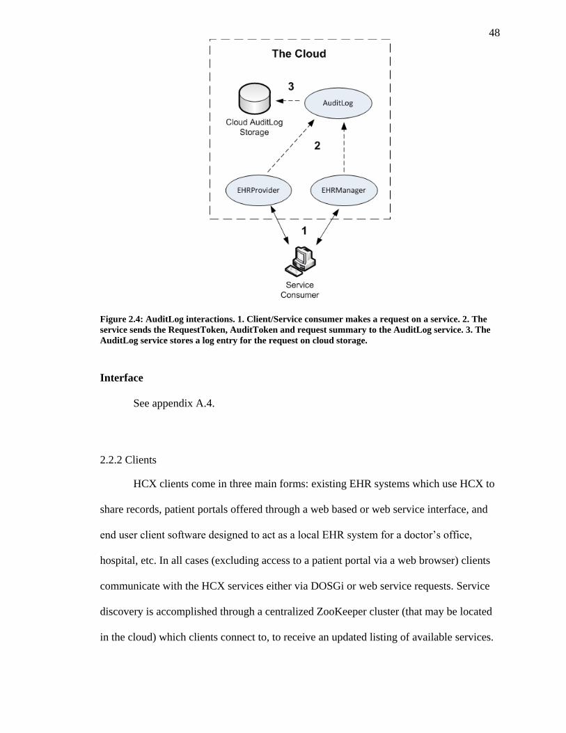
48
Figure 2.4: AuditLog interactions. 1. Client/Service consumer makes a request on a service. 2. The
service sends the RequestToken, AuditToken and request summary to the AuditLog service. 3. The
AuditLog service stores a log entry for the request on cloud storage.
Interface
See appendix A.4.
2.2.2 Clients
HCX clients come in three main forms: existing EHR systems which use HCX to
share records, patient portals offered through a web based or web service interface, and
end user client software designed to act as a local EHR system for a doctor’s office,
hospital, etc. In all cases (excluding access to a patient portal via a web browser) clients
communicate with the HCX services either via DOSGi or web service requests. Service
discovery is accomplished through a centralized ZooKeeper cluster (that may be located
in the cloud) which clients connect to, to receive an updated listing of available services.
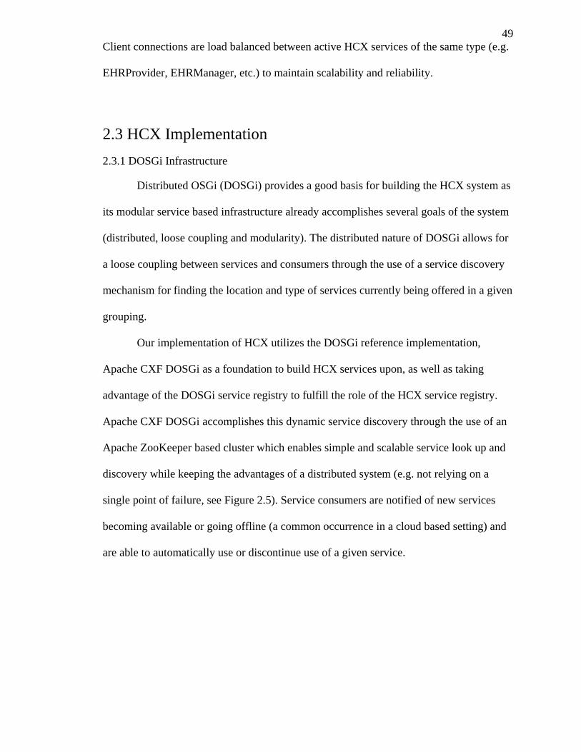
49
Client connections are load balanced between active HCX services of the same type (e.g.
EHRProvider, EHRManager, etc.) to maintain scalability and reliability.
2.3 HCX Implementation
2.3.1 DOSGi Infrastructure
Distributed OSGi (DOSGi) provides a good basis for building the HCX system as
its modular service based infrastructure already accomplishes several goals of the system
(distributed, loose coupling and modularity). The distributed nature of DOSGi allows for
a loose coupling between services and consumers through the use of a service discovery
mechanism for finding the location and type of services currently being offered in a given
grouping.
Our implementation of HCX utilizes the DOSGi reference implementation,
Apache CXF DOSGi as a foundation to build HCX services upon, as well as taking
advantage of the DOSGi service registry to fulfill the role of the HCX service registry.
Apache CXF DOSGi accomplishes this dynamic service discovery through the use of an
Apache ZooKeeper based cluster which enables simple and scalable service look up and
discovery while keeping the advantages of a distributed system (e.g. not relying on a
single point of failure, see Figure 2.5). Service consumers are notified of new services
becoming available or going offline (a common occurrence in a cloud based setting) and
are able to automatically use or discontinue use of a given service.
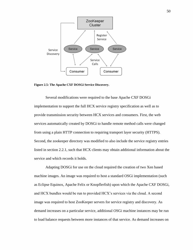
50
Figure 2.5: The Apache CXF DOSGi Service Discovery.
Several modifications were required to the base Apache CXF DOSGi
implementation to support the full HCX service registry specification as well as to
provide transmission security between HCX services and consumers. First, the web
services automatically created by DOSGi to handle remote method calls were changed
from using a plain HTTP connection to requiring transport layer security (HTTPS).
Second, the zookeeper directory was modified to also include the service registry entries
listed in section 2.2.1, such that HCX clients may obtain additional information about the
service and which records it holds.
Adapting DOSGi for use on the cloud required the creation of two Xen based
machine images. An image was required to host a standard OSGi implementation (such
as Eclipse Equinox, Apache Felix or Knopflerfish) upon which the Apache CXF DOSGi,
and HCX bundles would be run to provided HCX’s services via the cloud. A second
image was required to host ZooKeeper servers for service registry and discovery. As
demand increases on a particular service, additional OSGi machine instances may be run
to load balance requests between more instances of that service. As demand increases on
51
the service registry, more ZooKeeper machine instances may be run to add additional
ZooKeeper servers to the cluster. This set-up is shown in Figure 2.6 and Figure 2.7.
The OSGi machine image was created with Pax Runner
(http://team.ops4j.org/wiki/display/paxrunner/Pax+Runner) (a tool for provisioning OSGi
bundles in a range of OSGi frameworks), installed and configured to automatically start
an Equinox (http://eclipse.org/equinox/) OSGi console upon booting. Once started, the
Apache CFX’s DOSGi OSGi bundle and its dependencies were set to be automatically
loaded to support HCX services that would be run on this instance. Additionally several
custom scripts were installed to deal with the initialization data from the Service
Controller, download the appropriate HCX bundles (based on the Service Controller data)
and start their execution in Equinox. The ZooKeeper image simply contained an Apache
ZooKeeper install configured to join the ZooKeeper cluster and provide registry services
to the cloud.
Figure 2.6: Xen based machine images to support DOSGi on the cloud.
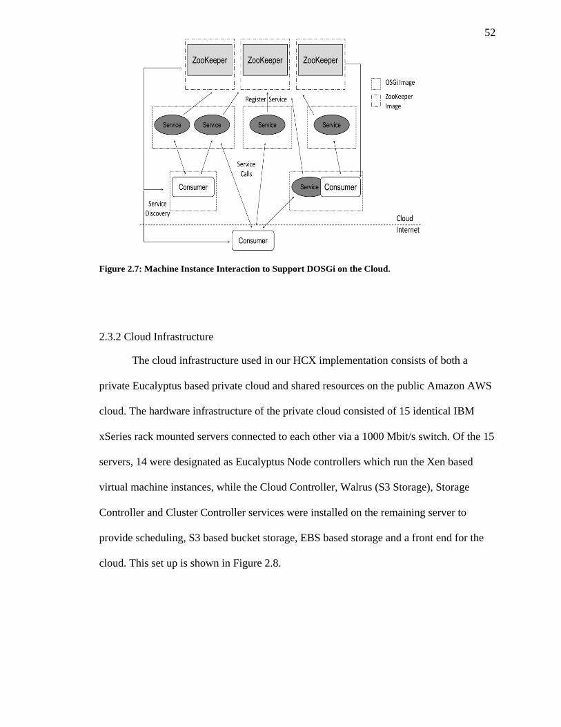
52
Figure 2.7: Machine Instance Interaction to Support DOSGi on the Cloud.
2.3.2 Cloud Infrastructure
The cloud infrastructure used in our HCX implementation consists of both a
private Eucalyptus based private cloud and shared resources on the public Amazon AWS
cloud. The hardware infrastructure of the private cloud consisted of 15 identical IBM
xSeries rack mounted servers connected to each other via a 1000 Mbit/s switch. Of the 15
servers, 14 were designated as Eucalyptus Node controllers which run the Xen based
virtual machine instances, while the Cloud Controller, Walrus (S3 Storage), Storage
Controller and Cluster Controller services were installed on the remaining server to
provide scheduling, S3 based bucket storage, EBS based storage and a front end for the
cloud. This set up is shown in Figure 2.8.
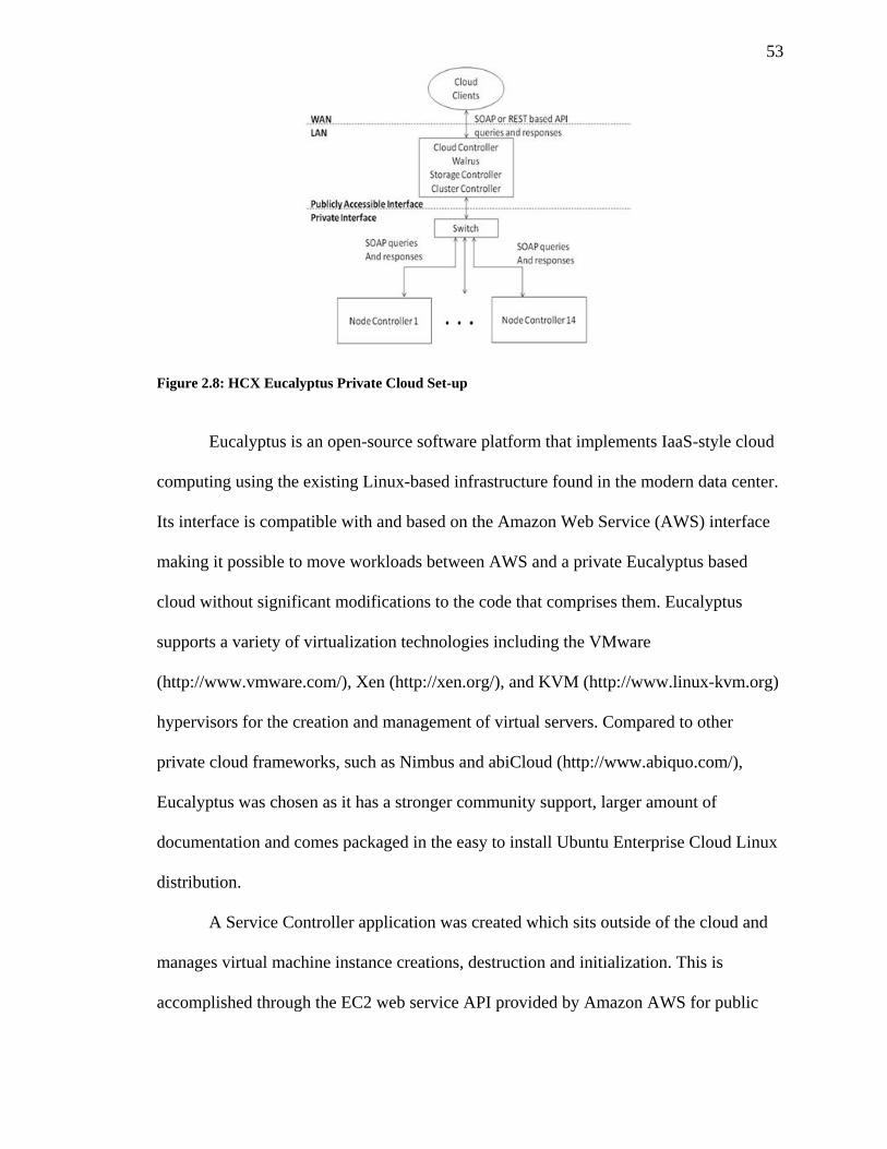
53
Figure 2.8: HCX Eucalyptus Private Cloud Set-up
Eucalyptus is an open-source software platform that implements IaaS-style cloud
computing using the existing Linux-based infrastructure found in the modern data center.
Its interface is compatible with and based on the Amazon Web Service (AWS) interface
making it possible to move workloads between AWS and a private Eucalyptus based
cloud without significant modifications to the code that comprises them. Eucalyptus
supports a variety of virtualization technologies including the VMware
(http://www.vmware.com/), Xen (http://xen.org/), and KVM (http://www.linux-kvm.org)
hypervisors for the creation and management of virtual servers. Compared to other
private cloud frameworks, such as Nimbus and abiCloud (http://www.abiquo.com/),
Eucalyptus was chosen as it has a stronger community support, larger amount of
documentation and comes packaged in the easy to install Ubuntu Enterprise Cloud Linux
distribution.
A Service Controller application was created which sits outside of the cloud and
manages virtual machine instance creations, destruction and initialization. This is
accomplished through the EC2 web service API provided by Amazon AWS for public
54
cloud instances and through the Eucalyptus EC2 based API for private cloud instances.
Further details on the role of the service controller are given in section 3.2.
2.4 Conclusions
While the DOSGi based HCX architecture presented in this chapter does not
provide the necessary security or data privacy we desire, it does offer a scalable
framework on which a more complex system that enforces role based security policies
may be built. We have shown how DOSGi may be adapted to a cloud based environment
by distributing services between machine instances and using a similar method for
creating a zookeeper cluster for service discovery. We have also described and
introduced a set of services for sharing EHRs, creating patient portals, maintaining an
audit log and offering administrative functions. The proceeding chapters take the cloud
environment and services introduced here and add systems for enforcing role based
access policies and data privacy through attribute based encryption.
55
Chapter 3
3 Developing a Role Based Access Control
and Single-Sign-On System for the Cloud
3.1 Role Based Access Control
Traditionally access control has been limited to discretionary access control
(DAC) and mandatory access control (MAC) models that use access control lists (ACLs)
to rigidly map users and groups to low level data objects. These approaches may perform
well for controlling access on simple local systems, such as a standalone computer’s file
system, however, it becomes increasingly difficult to maintain and manage user
permissions when they are applied to more complex and less rigid systems. Enterprise
and cloud environments require more flexible models of access control that are able to
more closely represent the organizational role a user plays in these environments. Role
based access control (RBAC) offers a more general solution that is flexible enough to
model the real life roles and responsibilities of the members of most organizations, in fact
it is even generic enough to enforce the traditional MAC and DAC access policies if
needed (Osborn, Sandhu, & Munawer, 2000).
Users of cloud based applications may require different levels of access to
multiple cloud based services, capable of performing various abstract operations on lower
level data objects. Managing permissions for accounts spanning services made available
via a cloud infrastructure, requires a model that can preserve the security of traditional
access control systems while providing a level of abstraction which allows administrators
56
to implement high level policies that are independent of the low level infrastructure that
compose the cloud.
3.1.1 RBAC Related Research
While much work has been done in the area of role based access control
(Ferraiolo, Sandhu, Gavrila, Kuhn, & Chandramouli, 2001) (Ferraiolo & Kuhn, 1992)
(Sandhu, Coyne, Feinstein, & Youman, 1996) (Yao, Moody, & Bacon, 2002) little has
been done in terms of adapting this model to the cloud computing paradigm. Based on the
identified challenges inherent to cloud computing (see section 1.2) we have identified the
following qualities needed in a RBAC model to meet the demands of the cloud:
1. Scalable: An RBAC system for the cloud needs to be designed to scale alongside
the cloud or the dynamic scalability advantages gained from using cloud
computing will be lost. This includes reducing or eliminating potential
bottlenecks including connections to systems outside of the cloud and centralized
services only offered from a single physical or virtual system.
2. Distributed: A cloud based RBAC system should match the distributed nature of
the cloud, offering services from multiple virtualized systems rather than a more
traditional centralized server setup. A clear namespace for identifying objects,
roles, users, etc. among different systems distributed throughout the cloud and
client systems are required. Ideally, such a system would be able to handle the
joining and parting of different nodes which compose the system (caused by
machine instances being created and destroyed to meet demand) with little
difficulty and transparently to the RBAC system’s end users.
57
3. Auditable: The RBAC systems should be capable of maintaining logs of users’
actions and role activations within the system and ensure that no part of the
system has been tampered with or compromised by a malicious user or
administrator.
4. Confidential: A user’s identity and personal details should be kept from services
using the RBAC system for authentication unless necessary for their function or
authentication method. This becomes more critical on a public cloud setting
where the cloud provider may not always be trusted.
5. Straightforward Administration: Proper administration of an RBAC system is
critical for ensuring the security of the systems which utilize it. Administration of
roles, users, rules, permissions, etc. should be reasonably straightforward and well
understood to RBAC administrators.
6. Reliable: To maximize reliability, centralized points of failure should be
eliminated or minimalized. Having cloud services dependent on a RBAC system
for authentication means any failure or downtime for that system translates to
downtime of all cloud services. If a RBAC system relies on a central server or
service, there should be some level of failover protection to diminish the effect of
downtime on end users and services.
The following section reviews two popular and relevant RBAC models and offers
criticism based on the qualities of an ideal cloud based RBAC system identified above.
58
3.1.1.1 The ANSI RBAC Standard
3.1.1.1.1 Summary
Several role based access control models have been developed in recent years that
have expanded on and standardized the core ideas behind RBAC. One of the most
notable is the effort by the National Institute of Standards and Technology (NIST)
(Ferraiolo, Sandhu, Gavrila, Kuhn, & Chandramouli, 2001) to create a standardized
template for which the majority of RBAC implementations can be based and expanded
upon. The NIST model integrates several previously published RBAC
models/frameworks (Sandhu, Coyne, Feinstein, & Youman, 1996) (Ferraiolo & Kuhn,
1992) into the standard for RBAC adopted as ANSI INCITS 359-2004 (InterNational
Committee for Information Technology Standards, 2004). This model divides RBAC into
four functional components: Core RBAC and three optional components (Hierarchical
RBAC, Static Separation of Duty Relations and Dynamic Separation of Duty Relations),
which may be combined to create the basis for implementing an RBAC package.
Core RBAC maps together the five basic elements of a role based access control
system (users, roles, objects, operations and permissions) to assign users to roles, and
roles to permissions, where permissions are in turn mapped between operations and
objects. User sessions are also present in the Core RBAC model, allowing users to
activate a subset of roles they have been assigned in a given session. Figure 3.1 illustrates
the many-to-many mapping between these basic elements.
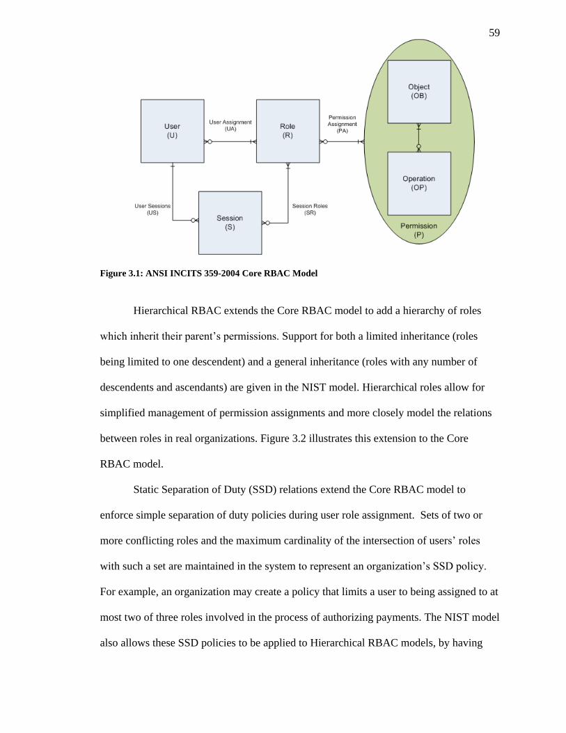
59
Figure 3.1: ANSI INCITS 359-2004 Core RBAC Model
Hierarchical RBAC extends the Core RBAC model to add a hierarchy of roles
which inherit their parent’s permissions. Support for both a limited inheritance (roles
being limited to one descendent) and a general inheritance (roles with any number of
descendents and ascendants) are given in the NIST model. Hierarchical roles allow for
simplified management of permission assignments and more closely model the relations
between roles in real organizations. Figure 3.2 illustrates this extension to the Core
RBAC model.
Static Separation of Duty (SSD) relations extend the Core RBAC model to
enforce simple separation of duty policies during user role assignment. Sets of two or
more conflicting roles and the maximum cardinality of the intersection of users’ roles
with such a set are maintained in the system to represent an organization’s SSD policy.
For example, an organization may create a policy that limits a user to being assigned to at
most two of three roles involved in the process of authorizing payments. The NIST model
also allows these SSD policies to be applied to Hierarchical RBAC models, by having
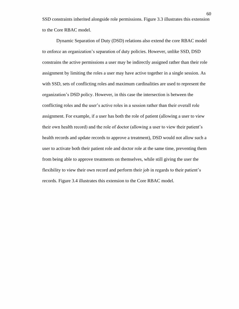
60
SSD constraints inherited alongside role permissions. Figure 3.3 illustrates this extension
to the Core RBAC model.
Dynamic Separation of Duty (DSD) relations also extend the core RBAC model
to enforce an organization’s separation of duty policies. However, unlike SSD, DSD
constrains the active permissions a user may be indirectly assigned rather than their role
assignment by limiting the roles a user may have active together in a single session. As
with SSD, sets of conflicting roles and maximum cardinalities are used to represent the
organization’s DSD policy. However, in this case the intersection is between the
conflicting roles and the user’s active roles in a session rather than their overall role
assignment. For example, if a user has both the role of patient (allowing a user to view
their own health record) and the role of doctor (allowing a user to view their patient’s
health records and update records to approve a treatment), DSD would not allow such a
user to activate both their patient role and doctor role at the same time, preventing them
from being able to approve treatments on themselves, while still giving the user the
flexibility to view their own record and perform their job in regards to their patient’s
records. Figure 3.4 illustrates this extension to the Core RBAC model.
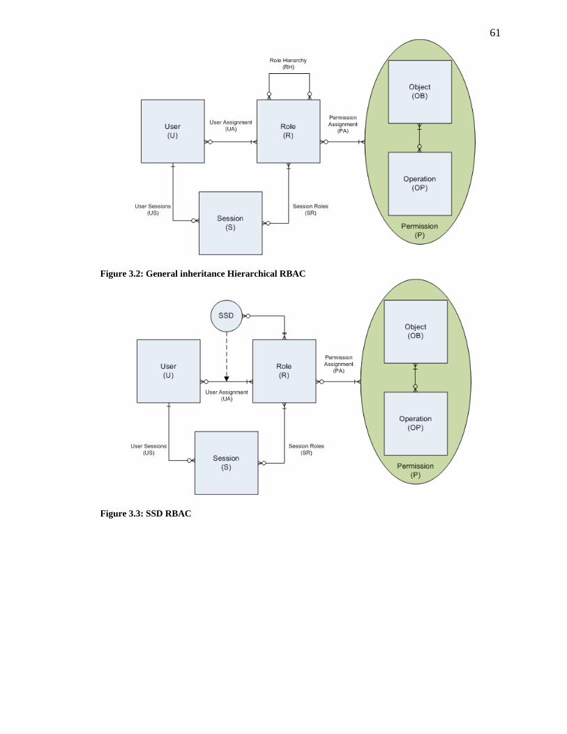
61
Figure 3.2: General inheritance Hierarchical RBAC
Figure 3.3: SSD RBAC
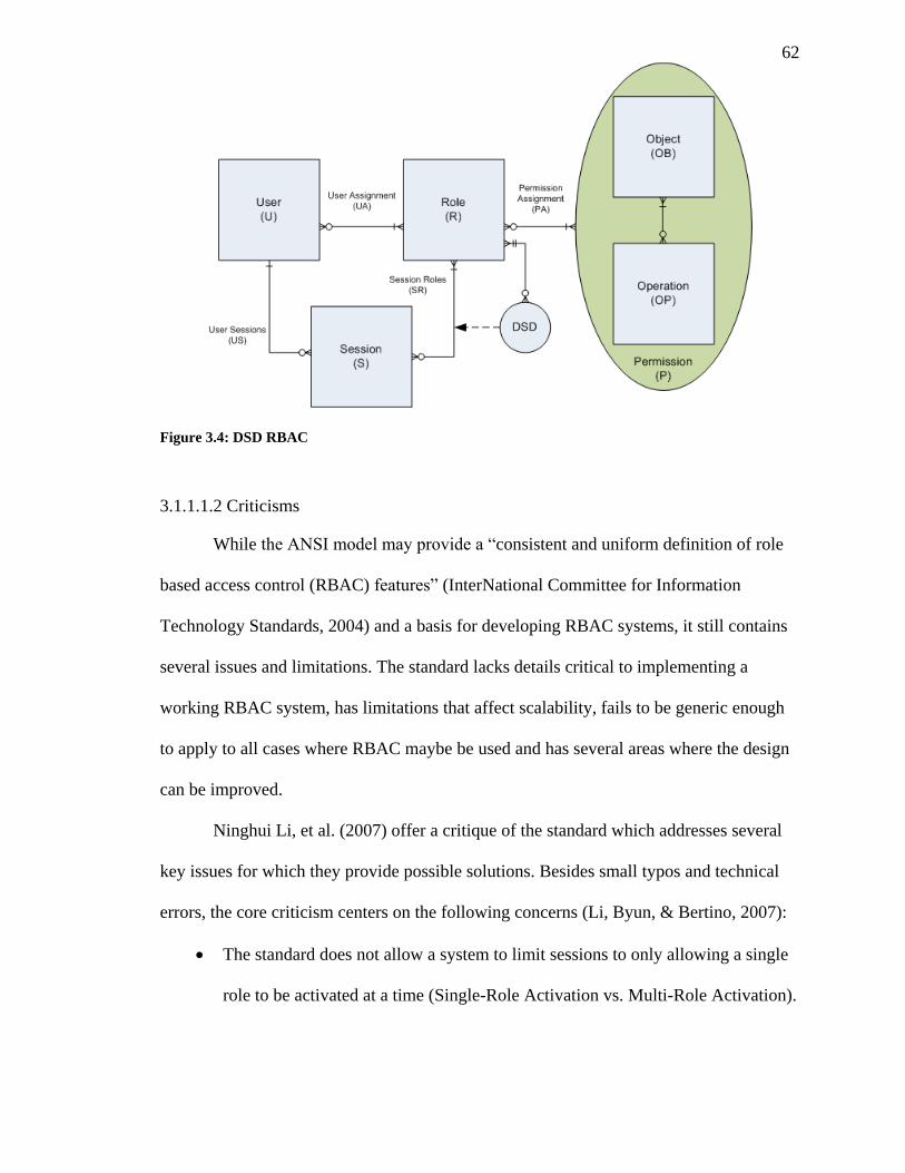
62
Figure 3.4: DSD RBAC
3.1.1.1.2 Criticisms
While the ANSI model may provide a “consistent and uniform definition of role
based access control (RBAC) features” (InterNational Committee for Information
Technology Standards, 2004) and a basis for developing RBAC systems, it still contains
several issues and limitations. The standard lacks details critical to implementing a
working RBAC system, has limitations that affect scalability, fails to be generic enough
to apply to all cases where RBAC maybe be used and has several areas where the design
can be improved.
Ninghui Li, et al. (2007) offer a critique of the standard which addresses several
key issues for which they provide possible solutions. Besides small typos and technical
errors, the core criticism centers on the following concerns (Li, Byun, & Bertino, 2007):
The standard does not allow a system to limit sessions to only allowing a single
role to be activated at a time (Single-Role Activation vs. Multi-Role Activation).
63
Having Hierarchical RBAC use a partial order creates issues when updating the
role hierarchy.
Ambiguity of the role hierarchy.
Single-Role Activation (SRA), limiting sessions to a single role, provides several
advantages over the Multi-Role Activation (MRA) endorsed by the standard. The most
apparent being the simplification of enforcing the principle of least privilege (as only one
role may be activated, it is not possible to activate conflicting roles simultaneously).
Alternatively, MRA requires the implementation and proper configuration of additional
mechanisms, such as dynamic separation of duty (as used in the standard), to support the
principle. Secondly, SRA requires roles to be explicitly created to allow users to have a
given set of permissions active at the same time. With MRA, roles must be explicitly
excluded from being activated simultaneously, requiring role administrators to review
each combination of roles for conflicts. This essentially boils down to a white list (SRA)
vs. black list (MRA) approach to least privilege, placing the standard’s use of a black list
methodology in conflict with the fail-safe defaults principle of “bas[ing] access decisions
on permission rather than exclusion” (Saltzer & Schroeder, 1975).
Ninghui Li, et al. (2007) argue that the use of a partial order to maintain role
hierarchies, such as is done in the ANSI and RBAC96 models, negatively effects the
excepted outcome of updates to the hierarchy in several cases. For example, in the case of
ANSI RBAC, the General Role Hierarchy (RH) is defined as follows (directly from
(InterNational Committee for Information Technology Standards, 2004)):
With the addition and deletion of inheritances being defined as:
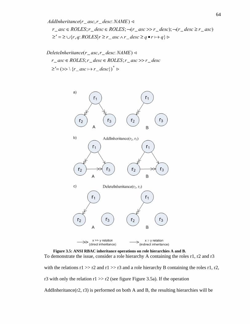
64
To demonstrate the issue, consider a role hierarchy A containing the roles r1, r2 and r3
with the relations r1 >> r2 and r1 >> r3 and a role hierarchy B containing the roles r1, r2,
r3 with only the relation r1 >> r2 (see figure Figure 3.5a). If the operation
AddInheritance(r2, r3) is performed on both A and B, the resulting hierarchies will be
Figure 3.5: ANSI RBAC inheritance operations on role hierarchies A and B.
65
equivalent and represented by the same partial order, with relations r1 >> r2, r2 >> r3 and
r1 ≥ r3 (as shown in figure Figure 3.5b). As the original relations that were explicitly
created are not persevered for further operations, this can lead to some what counter
intuitive results. For example, if the operation DeleteInheritance(r2, r3) is performed on
the resulting hierarchy in figure Figure 3.5b, to attempt to undo the last step, the resulting
hierarchy in both the cases of A and B will be that shown in figure Figure 3.5c, with only
the relation r1 >> r2. This could easily be seen as the excepted result for hierarchy B,
however the result for hierarchy A is not equivalent to the hierarchy before the
AddInheritance operation was performed (as shown in figure Figure 3.5c). This partial
order method for maintaining a role hierarchy fails to handle update operations in a way
that a role administrator would intuitively expect in many cases, leading to possible
unexpected loss of inheritance relations as was showing in figure Figure 3.5.
The last major issue raised by Ninghui Li, et al. (2007) relates to the ambiguity of
the ANSI standard’s general and limited role hierarchies. The current standard allows for
several different interpretations of the role hierarchy including those identified by
Ninghui Li, et al. (2007):
User Inheritance (UI): Users authorized for role r1 are also authorized for role
r2 given that r1 >> r2 (i.e. a user may activate any role that is inherited by a role
they are assigned).
Permission Inheritance (PI): Role r1 is authorized for all permissions role r2 is
authorized for, given that r1 >> r2 (i.e. a role is authorized for all permissions of
the roles which it inherits).
66
Activation Inheritance (AI): If role r1 is activated in a session then role r2 is
also activated given that r1 >> r2 (i.e. all roles inherited by an active role are also
activated in the given session).
Implementations are left to decide which interpretation (or set of interpretations) to use
without any standardization. However, picking the wrong interpretations can have
negative consequences on a system’s ability to enforce SSD and DSD rules. For
example, if PI is used without UI, users may bypass SSD rules excluding the use of roles
r1 and r2 by activating a role r3, where r3 >> r1 and r3 >> r2. Ninghui Li, et al.’s (2007)
analysis of the issue concludes with the recommendation of “[using] UI and PI at all
times and add AI whenever MRA is used.”.
In addition to the concerns raised by Ninghui Li, et al.’s (2007) critique, we have
identified several supplementary issues with the ANSI model that will have a significant
impact on RBAC systems both following this model and a distributed design (such as
those implemented for the cloud). These issues fall into the following categories:
1. Permission definition and operation-object mapping.
2. Lack of user groups or rule based groups.
3. Enforcing the principle of least privilege.
4. Issues for distrusted implementations.
5. User sessions.
6. Updating SSD constraints.
Permission Definition and Operation-Object Mapping
The ANSI standard defines a permission as approval to perform a given operation
on an object (“…any system resource subject to access control, such as a file, printer,
terminal, database record, etc.” (InterNational Committee for Information Technology
67
Standards, 2004)). However, this definition is somewhat simplistic for real world
applications. First, limiting an object to system resources would seem to exclude meta
structures, such as groupings of resources (e.g. a grouping of files not necessarily
contained in the same level of a file system hierarchy or with a common attribute) or
roles and permissions stored in the RBAC system, as well as possibly excluding
virtualized or remote resources such as virtual drive or a remote file share.
Second, the mapping of operations to objects largely ignores the properties of the
object or at a minimum requires many operations and many mappings to cover most
common permissions a system would need. For example, many file systems assign an
owner and group to files and directories as well as a set of permissible actions. To
emulate the same permissions with this operations-objects mapping, a permission for
each user/group would need to be created which contains the set of all mappings of
operations on files for which that user or group would have some level of access and
then mapped to the appropriate roles and users, resulting in many complex relations for
RBAC administrators to maintain. Alternatively, additional operations can be created to
check if a user meets some requirement of the underlying files system (e.g. that the user
is the owner of the file according to the file system), however, this removes the precise
knowledge of what resources a given user may have access to in the RBAC system and
breaks the operations-objects mapping as the permission only contains a set of
operations. Additionally, there may be cases where neither the object nor the local
system has knowledge of an object’s property for which it may be desired that
permissions be built around. For example, a printer in an office building has the physical
property of which floor of the building it is located on. It may be desired that a
permission be created that limits one role to only printing on a given floor but another
role to have full access to all printers. Traditionally, this would be accomplished by
68
creating a permission for each floor mapping the print operation to every printer on that
floor. However, if a RBAC system had the capability to map properties on-to objects and
contained more complex permissions, the permission could simply contain the rule that
the printing is allowed if the printer contains the property of being on the given floor.
This would allow for more natural RBAC administration, where administrators first map
properties on to objects and then create permissions by defining rules based on the
object’s properties and would also allow for greater reuse (e.g. if it was desired that a
permission be created to allow a role to stop a print job on a given floor).
The final issue with the standard’s permissions is the lack of detail on how
implementations will reference operations. The standard defines an operation as “…an
executable image of a program, which upon invocation executes some function for the
user” (InterNational Committee for Information Technology Standards, 2004) which
seems to suggest that the operation in the model’s permissions are a reference to a
specific executable program or service on the system and may vary for each object type.
For example, the edit operation listed for a file would be different from the edit operation
for a database. This requires the RBAC model to have some understanding of the
underlying system for which it provides access control and would increase the difficulty
of generating a list of users that have access to a standard operation such as “read” across
several different object types (e.g. a list of users that can view the content of a given set
of files and databases) as the operations would differ. A set of standard operations such
as “view”, “edit”, “copy”, “move”, “delete”, etc. with the option of manually adding
additional and more specific operations would greatly simplify permission
administration.
69
Lack of User Groups or Rule Based Groups
The next issue with the standard is the limited assignment of roles only to users.
Adding user groups to the model would allow for simpler RBAC administration when a
set of roles needs to be assigned to the same group of users, or if a group of users needed
to be temporarily assigned to a role, or required frequent changes in their assigned role.
Furthermore rule based user groups would allow for the assignment of roles based on
conditional rules. For example a group could be created whose members are based on an
IP address range allowing access to select resources based on a user’s IP, allowing a
network admin to limit access to critical objects to users on a trusted intranet.
Enforcing the Principle of Least Privilege
While the ANSI model complies with the principle of least privilege through its
support of per session role activation, it fails to enforce that the users of an implementing
system abide by the principle. Although the SSD and DSD components prevent users
from activating potentially conflicting roles, there are no mechanisms within the standard
which prevents or discourages users from constantly activating an assigned role with
higher than needed privileges for an assigned task. For example, if a user is assigned a
role with the permission granting it access to view a database record as well as a role with
permission to view and update the record, there is no mechanism to prevent or discourage
the user from using the second more powerful role for a task that only requires viewing a
record.
Issues for Distributed Implementations
The ANSI standard choses to omit implementation details for how RBAC
services might (or should) be provided in differing environments (e.g. distributed vs.
70
local), presumably to increase applicability of the model. However, many of the
administrative functions and formal operations would be extremely costly or difficult to
implement in anything but a centralized, server-client or local system. The administrative
functions for adding or changing an SSD constraint (CreateSsdSet, AddSsdRoleMember,
SetSsdSetCardinality, etc.) for example require that the resulting constraint is satisfied for
all related user-role assignments. In a distributed RBAC system it is likely that user
and/or roles would be distributed among multiple remote systems and such a check
would require querying every system for user-role assignments that may violate the new
constraint.
Also lacking in the standard is a standardized namespace for identifying objects,
roles, permissions and users across multiple remote systems. Such a standardized
namespace would be critical in a distrusted system so that elements of the RBAC could
be properly and uniquely identified and referenced, as well as easily located despite not
necessarily being local. Existing standards for locating and referencing resources, such as
the Uniform Resource Identifier (URI) (RFC 3986), Uniform Resource Locator (URL)
(RFC4266 and RFC4248), and Uniform Resource Name (URN)( RFC1737 and
RFC2141) could possibly serve this function, however, it may be more appropriate to
design or extend an existing naming standard around RBAC.
User sessions
Several of the administrative functions in the standard (including DeleteUser,
DeleteRole, AssignUser, DeassignUser, GrantPermission, and RevokePermission) leave
the handling of active sessions as implementation specific details. For example, if a user
has an active session when DeeleteUser is called, should the session be destroyed or
remain active until the user logs out of the system? Leaving these decisions as
71
implementation details causes several issues. First, this creates a large discrepancy
between systems implementing the same standard in terms of consistency when an
administrative function is performed, and second, the issue is deserving of further
discussion as the implications can be large for a system’s security. We have identified
three possible methods for dealing with active sessions after a direct (e.g.
GrantPermission, etc.) or indirect permission change (e.g. DeleteRole, AssignUser, etc.):
1. Leave all active sessions as they are.
2. Drop all affected user sessions.
3. Update sessions when possible (e.g. GrantPermission, RevokePermission, etc.),
drop when not (e.g. DeleteUser, DeassignUser, etc.).
The three options have various advantages and disadvantages in terms of easy to
implement, feasibility and security. The first option is the simplest to implement, works
in distributed or centralized systems, and is easily scaled, but any administrative function
which indirectly removes permissions from a user has the potential to leave an
opportunity for abuse if an active session exists for any user for whom the change effects.
For example, if a user may never be assigned roles R1 and R2 concurrently due to an
SSD restriction and an RBAC administrator changes a user’s assigned role from R1 to R2
while the user has an active session using role R1, the user will be able to create a second
session using R2 and bypass the SSD restriction as long as their first session remains
active. While Single-Role Activation or DSD could be used to prevent this case
(assuming all SSD rules were also DSD rules), the user would still have access to the
permissions granted to role R1 until the session expires despite the role being unassigned.
This could be a massive security issue in distributed RBAC systems where session
revocation is not possible or limited, and a malicious or compromised user needs to be
removed immediately. The second option removes the security issues of the first but has
72
the potential to inconvenience users with active sessions if a change is made to a live
system. Additionally, in distributed systems, revoking user sessions can be costly to
scalability if remote services need to be notified or need to be constantly checking a
session’s validity with a centralized server. The third option has the advantages of the
second while limiting any potential inconvenience users of the system may experience.
However, it would also present greater challenges and complexities for distributed
systems, requiring updated session information to be synchronised with all services in the
system.
3.1.1.2 OASIS Role-Based Access Control
3.1.1.2.1 Summary
OASIS role-based access control (Yao, Moody, & Bacon, 2002) provides an
architecture and model for secure service authentication and access with an open
distributed environment. Unlike most role based access control models, OASIS does
away with the traditional role hierarchy and does not use role delegation but instead an
appointment process. Rather than relying on a centralized role administrator to delegate
roles, the OASIS model uses a credential-based system for role activation whereby users
may activate roles based on the current credentials they possess and conditions relating to
the systems environment (e.g. current time, current task a user is performing, etc.).
Credentials are granted through appointments initiated by any user who is a member of
some role which grants the appointment ability for the given credential. For example, a
user may be granted a new credential upon obtaining a professional qualification which
will in turn grant access to a new set of roles in the system during role activation.
73
The OASIS model supports separation of duty constraints at the role activation
level (similar to dynamic separation of duty in the ANSI model) as a role activation rule.
Additional context based role activation rules beyond credentials and separation of duty
constraints are also supported through parameters in the extended model including time
based rules (roles only allowed during set dates or times of day), and role prerequisites (a
session with role r1 must be active before role r2 may be active). Furthermore, many
additional rules are supported through extensions to the basic RBAC model including
support for workflow systems, team-based systems, and content-based access control.
W. Yao, et al. (2002) argue that their model of appointment has several
advantages over the delegation model including well-defined and controlled privilege
propagation, prevention of cascading delegation, and the ability for a user to grant
privileges that they do not necessarily have to possess. Additionally, appointment can be
viewed as generifying delegation as delegation becomes a special case of appointment in
which a user grants a credential which in turn allows activation of the same role as the
granting user.
The model provides three methods of credential revocation which a system may
implement; appointer-only revocation, appointer-role revocation and system-managed
revocation. Appointer-only revocation allows only the appointer of a credential to revoke
it from a user; this tends to model how many organizations function in real world
scenarios. Appointer-role revocation allows any user with the ability to grant a credential
to also revoke it from a user; this is more preferable in cases where the original appointer
may not always be available to revoke a credential in cases of emergency (e.g. a
malicious user abusing the system). Finally system-managed revocation allows the
system to automatically revoke a credential under set conditions. Three possible
conditions for system-managed revocation are supported; time-based revocation, task-
74
based revocation and session-based revocation. Time-based system revocation forces an
appointment to expire at a set time, task-based system revocation revokes an appointment
once the user has completed some task (normally the task that required the appointment)
and session-based system revocation in which appointments are revoked once the user’s
session ends or when the appointer’s session ends.
3.1.1.2.2 Criticisms
The OASIS RBAC model provides a new take on the role based model, replacing
direct role delegation with automatic role appointments based on a set of rules, and a
user’s qualifications. However, we have identified several issues with the OASIS model
that would hinder its adoption in the cloud. These issues fall into the following
categories:
1. Rejection of the Role Hierarchy
2. Scalability
3. Appointment vs. Delegation
4. Security
Rejection of the Role Hierarchy
Yao, Moody, & Bacon (2002) reject the need for a role hierarchy, viewing them
as a violation of the principle of least privilege and questioning their utility in practice,
despite their acceptance in many common models (Ferraiolo, Sandhu, Gavrila, Kuhn, &
Chandramouli, 2001) (Nyanchama & Osborn, 1999) (Sandhu, Bhamidipati, & Munawer,
1999). They base this view mostly on the criticism offered by C. Goh and A. Baldwin
(1998) which argues that role hierarchies rarely accurately model the real world roles of
75
an organization (Goh & Baldwin, 1998). While the role hierarchy does add additional
complexities to a RBAC model and can in some cases affect the application of the
principle of least privilege, we believe it is critical for several key reasons, including
proper support of a distributed cloud RBAC.
First, while introducing a role hierarchy may add additional complexities during
the systems implementation, it often simplifies role administration once the system is in
use. Take for example the case where a system has a default user role that grants a set of
permissions to access various subsystems (such as viewing publicly available documents
shared by other users of the system), several other roles needing to contain all
permissions of the user role plus additional permissions to various sub systems (such as
viewing documents limited to select roles), and an administrator role containing the
privileges of all other roles. Without a RBAC hierarchy, an RBAC administer would be
left with two choices: either creating each role and manually adding the permissions of
the lower role (e.g. each role would manually be given the permissions of the user role
and the administrator role would be given the permissions of all other roles) or creating
each role missing the permissions of the lower role and requiring users to activate
multiple roles. The first choice is problematic for maintaining a role’s permission set (i.e.
when the user role changes, every other role needs its set updated manually) and the
creation of a large number of roles sharing the same subset of permissions is time
consuming and error-prone. The second choice, while avoiding issues of updating all
role’s permission sets when the user role changes, requires a RBAC system to support
multiple role activations (which is not always desired) and additionally requires that users
of the system activate the lower roles with the higher ones (e.g. the default user role
would need to be activated with any more privileged role). If not automated this would
76
lower the usability of the system, requiring that users know which set of roles need to be
activated in conjunction with a given role to perform a task.
Secondly, while the claim that a role hierarchy creates issues for enforcing the
principle of least privilege is true for some cases, such as would be the case if all system
administrators were assigned the max role (the role which inherits permissions from all
others), it is not necessarily the case when the role hierarchy/graph is properly managed.
In fact a hierarchy of roles can even aid in the automatic activation and deactivation of
roles as needed. Consider the following case where role hierarchy is created such that a
minimal role (containing only bare minimum permissions to use the system) is
extended/inherited by each subsequent role which is in turn extended/inherited by any
role whose permission set contains a subset equal to the permission set of another role
until a maximum role is reached that contains the set of all permissions such that there is
a path from the minimum role to the maximum role through all roles. In this case there is
a clear path that role escalation can follow such that a user may start by activating the
least privileged role (the minimum role) and move along the path of roles they are
assigned when a higher level of privilege is needed (reversely, roles may be switched
with lower privileged roles when the level of access is no longer needed). Proper creation
of roles (such that they do not contain unnecessary permissions for tasks of a member of
that role) and a mechanism to encourage users to only activate the minimum role required
for a given task can counter most violations of the principle of least privilege that may
occur from the use of a role hierarchy.
Finally, a lack of a role hierarchy may pose an issue for a distributed RBAC
system with equal domains. In some cases it may be desired that a certain domain or
entity “own” a role or permission, such that they are the only one authorized to make
changes to that role or assign that permission. For example, a hospital may divide their
77
RBAC system into domains represented by the real departments of the organization such
that the administration holds the main sets of permissions and common roles. The
administration could then allow certain roles to be extended/inherited by roles of other
specified domains such that they may assign their own permission upon it. For example,
the administration could create a role called “accounts” which enables the holder to
access the hospitals accounting records and grant the accounts department/domain the
right to extended it by having a set of roles inherit its permissions. The accounts
department could then add their own specific permissions to create fine grained access
control to their own department’s roles (this could be accomplished either with negative
permissions which remove permissions from a parent role or more likely by having the
accounting system require that a user has some subset of permissions from the “accounts”
role in addition to some subset of permissions from a child role created by the accounts
domain to access or perform an operation on a given resource). This enables the
administration domain to have ultimate control over their permissions while allowing
other domains to still add fine grade control and add their own roles (Note that we present
such a distributed RBAC system in section 3.1.2).
Scalability
Another issue with the OASIS model is the requirement to have a notification
system between RBAC systems, user credential database and the systems using their
access control services. In theory the notification system provides means to notify
services when a user’s credentials or other requirements (which determine a user’s role)
change, are removed or new credentials are added. Additionally, this mechanism allows
for the immediate revocation of a user’s sessions in the case of a compromised account or
malicious behavior. While notifications allow for quicker responses to changes in a user’s
78
role sets (via changes in their credentials), it creates scalability issues for large scale
distributed RBAC systems. In such systems, which might involve thousands of users and
RBAC service consumers, where user and credential database updates may trigger
notifications to a large set of services and each service needs to maintain a notification
channel with the role issuer, scalability may quickly become an issue. As there are
currently no large scale OASIS implementations and the notification specification is
somewhat vague, it is currently difficult to fully evaluate the model’s scalability.
Appointment vs. Delegation
Unlike more traditional RBAC models, OASIS uses a system of appointment
rather than role delegation. In the OASIS model any user active in an appointment role
may grant other users of the system credentials for which the appointment role
authorizes. This allows for cases such as a hospital administrator granting medical
credentials to other users (such as doctors) without themself having the given credential
(this in opposition to delegation models where a user must have role or permission to
further delegate it to another user). OASIS roles are then granted based on a rule set
listing the required credentials to activate a role. While this method simplifies role
administration (as no direct mapping of users to roles is required) it adds some
complexities in terms of calculating a user’s possible permission set, preventing
accidental role appointments and creating potentially complex rule sets for assigning
roles.
In RBAC models such as the ANSI standard, ARBAC’96, etc. calculating the
overall possible permission set of a user (i.e. the set of permissions a user may access
through role activation) is somewhat trivial; the set of all roles a user may activate are
found, and then the set of all permissions those roles are mapped to are found, which
79
together compose the user’s overall permission set. In OASIS, role appointment is based
on potentially complex rules involving both the user’s credentials and environment
variables such as the current date/time. This means that the set of possible permissions a
user may access through role activation is not static but is changing based on
environment variables that may be different on each system a user may have access to.
While the ability to accurately calculate such a set of permissions is not critical to the
function of such an RBAC system, it may be important for its administration (i.e.
allowing an RBAC administer to view what permissions a user may be granted through
role activation).
As no administrator is necessarily responsible for direct role assignment or
delegation, it may quickly become confusing as to what credential may indirectly grant
what role in large OASIS based RBAC system. A hospital administer with the ability to
grant medical based credentials in the system may not have a full understanding of the
effect they will have on set of roles a user may activate. In many cases a user of the
system may come to such an administer requesting access to a particular permission (e.g.
permission to sign off on a lab report while the normal supervisor is away), however, it
may not necessarily be clear what credential needs to be appointed to the user to access
this permission. This kind of role appointment also is largely dependent on an RBAC
administer correctly identifying what credentials and rules should grant every role. For
large organizations this may be a daunting task where simple mistakes may grant
normally unauthorized users powerful roles. Traditional role delegation requires an
RBAC administer to directly assign roles to users reducing the possibility of error and
limiting its effect to a single user (or single group if roles may be delegated to groups of
users at once).
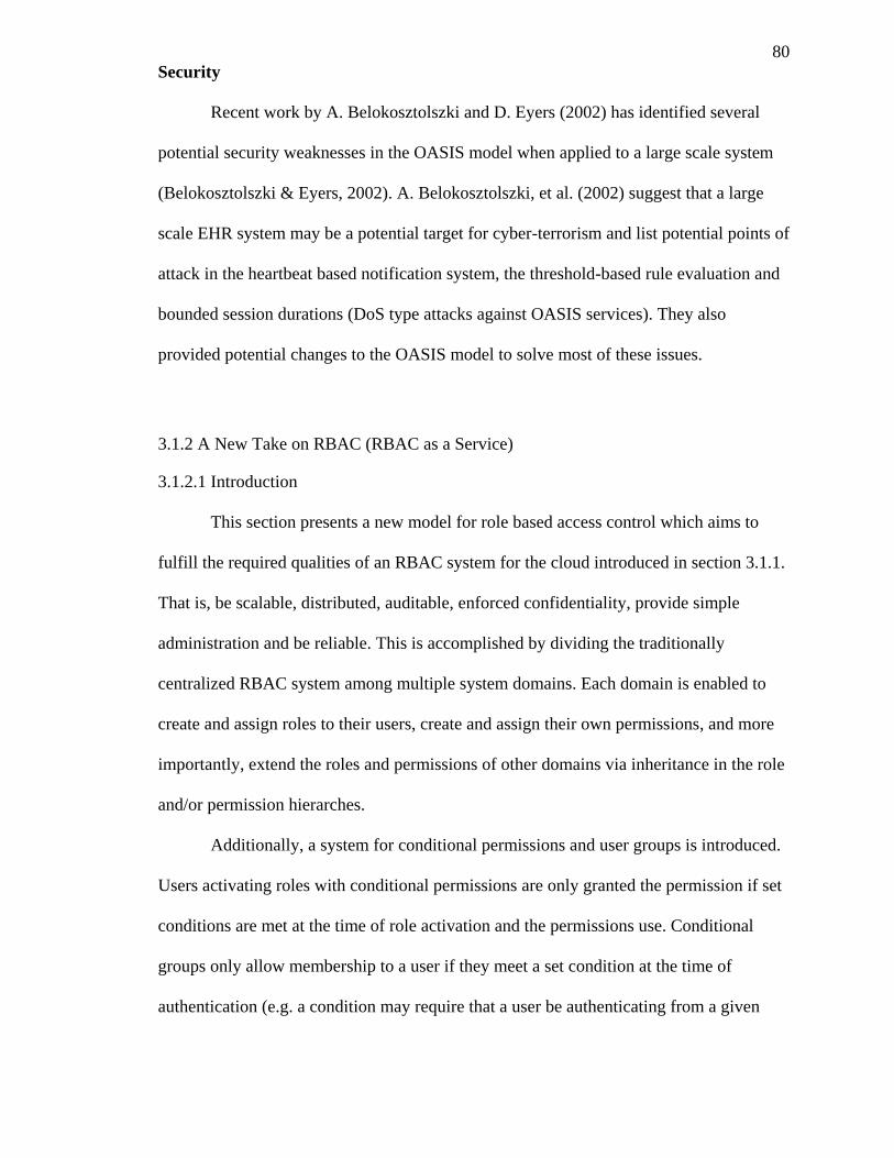
80
Security
Recent work by A. Belokosztolszki and D. Eyers (2002) has identified several
potential security weaknesses in the OASIS model when applied to a large scale system
(Belokosztolszki & Eyers, 2002). A. Belokosztolszki, et al. (2002) suggest that a large
scale EHR system may be a potential target for cyber-terrorism and list potential points of
attack in the heartbeat based notification system, the threshold-based rule evaluation and
bounded session durations (DoS type attacks against OASIS services). They also
provided potential changes to the OASIS model to solve most of these issues.
3.1.2 A New Take on RBAC (RBAC as a Service)
3.1.2.1 Introduction
This section presents a new model for role based access control which aims to
fulfill the required qualities of an RBAC system for the cloud introduced in section 3.1.1.
That is, be scalable, distributed, auditable, enforced confidentiality, provide simple
administration and be reliable. This is accomplished by dividing the traditionally
centralized RBAC system among multiple system domains. Each domain is enabled to
create and assign roles to their users, create and assign their own permissions, and more
importantly, extend the roles and permissions of other domains via inheritance in the role
and/or permission hierarches.
Additionally, a system for conditional permissions and user groups is introduced.
Users activating roles with conditional permissions are only granted the permission if set
conditions are met at the time of role activation and the permissions use. Conditional
groups only allow membership to a user if they meet a set condition at the time of
authentication (e.g. a condition may require that a user be authenticating from a given
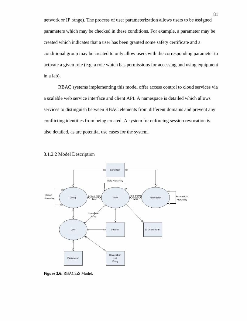
81
network or IP range). The process of user parameterization allows users to be assigned
parameters which may be checked in these conditions. For example, a parameter may be
created which indicates that a user has been granted some safety certificate and a
conditional group may be created to only allow users with the corresponding parameter to
activate a given role (e.g. a role which has permissions for accessing and using equipment
in a lab).
RBAC systems implementing this model offer access control to cloud services via
a scalable web service interface and client API. A namespace is detailed which allows
services to distinguish between RBAC elements from different domains and prevent any
conflicting identities from being created. A system for enforcing session revocation is
also detailed, as are potential use cases for the system.
3.1.2.2 Model Description
Figure 3.6: RBACaaS Model.
82
The Role Based Access Control as a Service (RBACaaS) model is based on the
NIST standard and aims to resolve several of the issues with the NIST standard and
provide distributed role based access control services from the cloud via a web service
interface. The core model (as shown in Figure 3.6) is composed of four main elements;
Users, Groups, Roles and Permissions. Users represent any actor in a system for which
access control may need to be applied (e.g. web services, real persons, third party
systems, etc.). Groups represent a subset of users which share the same roles based on
their membership in the group. Groups allow for simplified administration when it is
common for multiple users to fulfill the same set of roles in a system; our model also
enables the conditional mapping of users to roles based on user and system parameters.
All groups are part of the group tree (as shown in Figure 3.7) and inherit the roles of their
parent group node assuming the set conditions are met.
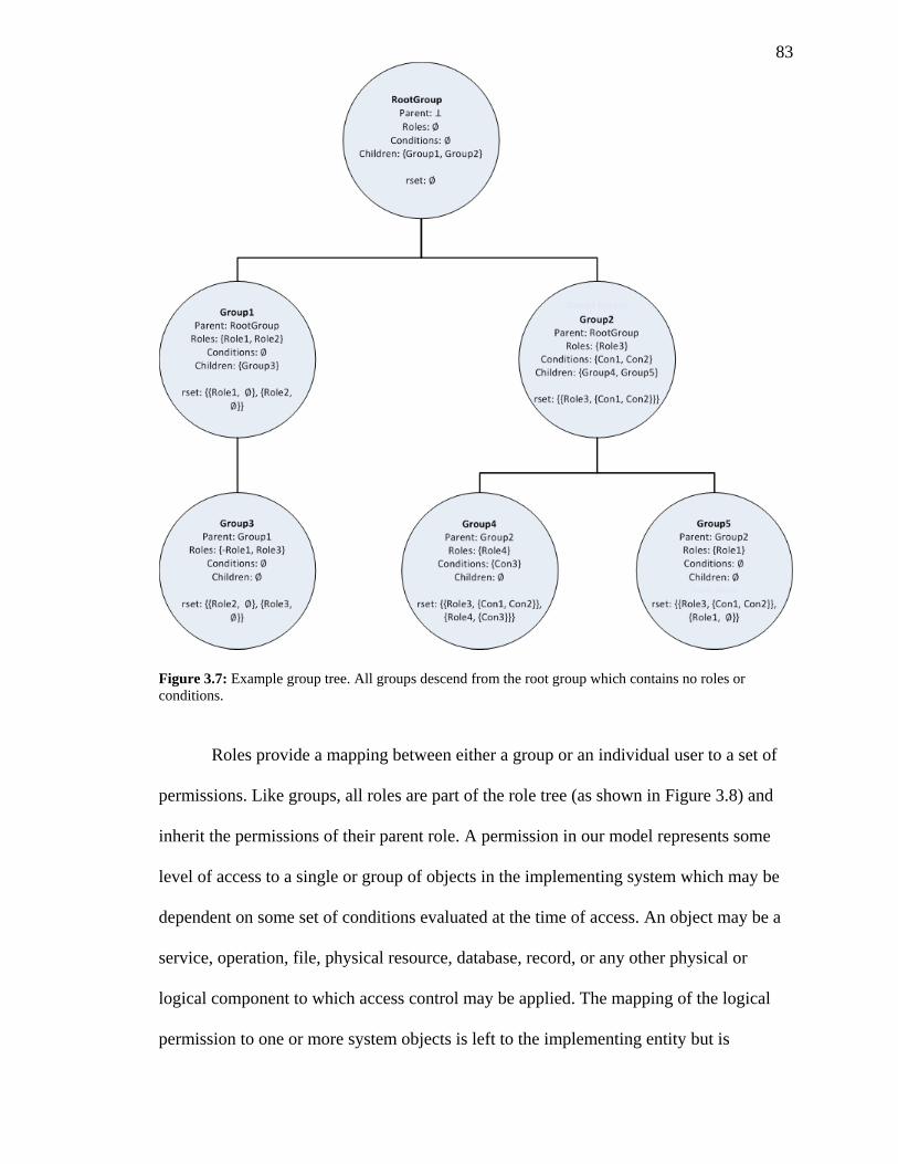
83
Figure 3.7: Example group tree. All groups descend from the root group which contains no roles or
conditions.
Roles provide a mapping between either a group or an individual user to a set of
permissions. Like groups, all roles are part of the role tree (as shown in Figure 3.8) and
inherit the permissions of their parent role. A permission in our model represents some
level of access to a single or group of objects in the implementing system which may be
dependent on some set of conditions evaluated at the time of access. An object may be a
service, operation, file, physical resource, database, record, or any other physical or
logical component to which access control may be applied. The mapping of the logical
permission to one or more system objects is left to the implementing entity but is
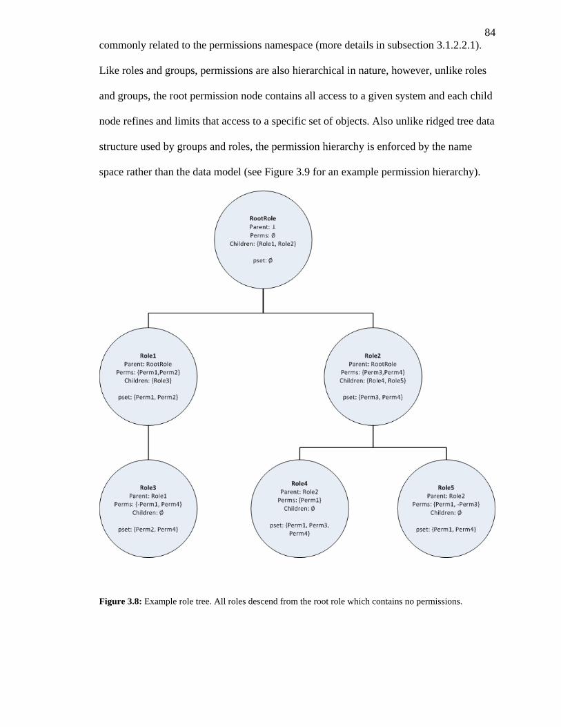
84
commonly related to the permissions namespace (more details in subsection 3.1.2.2.1).
Like roles and groups, permissions are also hierarchical in nature, however, unlike roles
and groups, the root permission node contains all access to a given system and each child
node refines and limits that access to a specific set of objects. Also unlike ridged tree data
structure used by groups and roles, the permission hierarchy is enforced by the name
space rather than the data model (see Figure 3.9 for an example permission hierarchy).
Figure 3.8: Example role tree. All roles descend from the root role which contains no permissions.
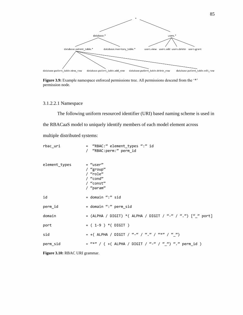
85
Figure 3.9: Example namespace enforced permissions tree. All permissions descend from the ‘*’
permission node.
3.1.2.2.1 Namespace
The following uniform resourced identifier (URI) based naming scheme is used in
the RBACaaS model to uniquely identify members of each model element across
multiple distributed systems:
rbac_uri = “RBAC:” element_types “:” id / “RBAC:perm:” perm_id
element_types = “user” / “group” / “role” / “cond” / “const” / “param” id = domain “:” sid perm_id = domain “:” perm_sid domain = (ALPHA / DIGIT) *( ALPHA / DIGIT / “-“ / “.”) [“_” port] port = ( 1-9 ) *( DIGIT ) sid = +( ALPHA / DIGIT / “-“ / “.” / “*” / “_”) perm_sid = “*” / ( +( ALPHA / DIGIT / “-“ / “_”) “.” perm_id )
Figure 3.10: RBAC URI grammar.
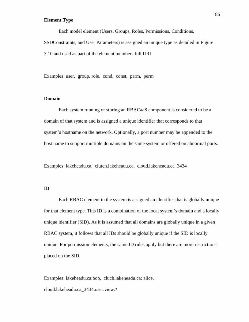
86
Element Type
Each model element (Users, Groups, Roles, Permissions, Conditions,
SSDConstraints, and User Parameters) is assigned an unique type as detailed in Figure
3.10 and used as part of the element members full URI.
Examples: user, group, role, cond, const, parm, perm
Domain
Each system running or storing an RBACaaS component is considered to be a
domain of that system and is assigned a unique identifier that corresponds to that
system’s hostname on the network. Optionally, a port number may be appended to the
host name to support multiple domains on the same system or offered on abnormal ports.
Examples: lakeheadu.ca, clutch.lakeheadu.ca, cloud.lakeheadu.ca_3434
ID
Each RBAC element in the system is assigned an identifier that is globally unique
for that element type. This ID is a combination of the local system’s domain and a locally
unique identifier (SID). As it is assumed that all domains are globally unique in a given
RBAC system, it follows that all IDs should be globally unique if the SID is locally
unique. For permission elements, the same ID rules apply but there are more restrictions
placed on the SID.
Examples: lakeheadu.ca:bob, cluch.lakeheadu.ca: alice,
cloud.lakeheadu.ca_3434:user.view.*
87
SID
The simple ID (SID) is a locally unique identifier for a member of an element
within that element’s namespace. The SID may be used to refer to the member within the
local domain, however, a full ID is required to refer to members from distributed
systems. For permissions, special restrictions apply to SIDs to create the permission
hierarchy such that every permission SID ends with “.*”, starts with a letter, digit or is
simply a single ‘*’, and contains at least one digit or letter between each set of ‘.’s.
Examples: bob, alice, user.view.*
3.1.2.2.1 Parameterization and Conditions
The RBACaaS model allows for both a static direct assignment of roles to users
and the dynamic assignment of roles to groups of users dependent on set conditions
evaluated at the time of session creation. Conditions are simple Boolean expressions
involving a constant value, user parameter or system parameter of the following
grammar:
condition = exp [ bool_op condition ] exp = var op var / [“!”] bool_var / [“!”] “(“ condition “)” var = const / user_param / system_param bool_var = boolean / user_param / system_param
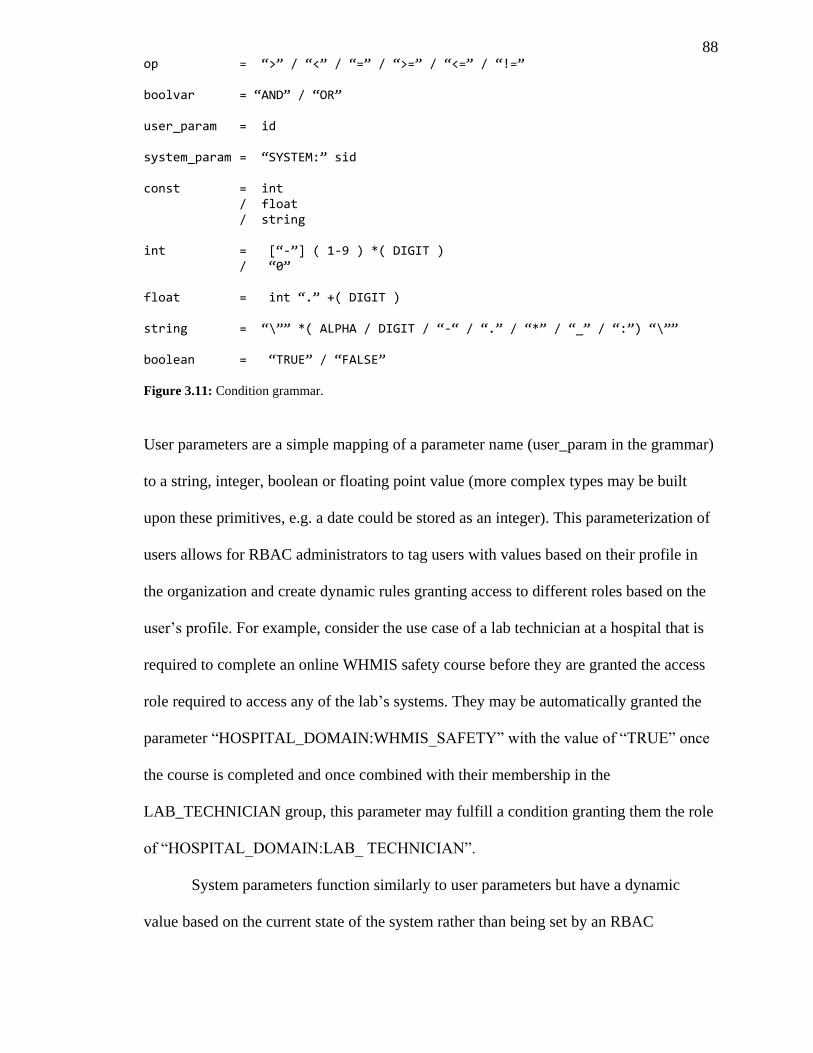
88 op = “>” / “<” / “=” / “>=” / “<=” / “!=” boolvar = “AND” / “OR” user_param = id system_param = “SYSTEM:” sid const = int / float / string int = [“-”] ( 1-9 ) *( DIGIT ) / “0” float = int “.” +( DIGIT ) string = “\”” *( ALPHA / DIGIT / “-“ / “.” / “*” / “_” / “:”) “\”” boolean = “TRUE” / “FALSE” Figure 3.11: Condition grammar.
User parameters are a simple mapping of a parameter name (user_param in the grammar)
to a string, integer, boolean or floating point value (more complex types may be built
upon these primitives, e.g. a date could be stored as an integer). This parameterization of
users allows for RBAC administrators to tag users with values based on their profile in
the organization and create dynamic rules granting access to different roles based on the
user’s profile. For example, consider the use case of a lab technician at a hospital that is
required to complete an online WHMIS safety course before they are granted the access
role required to access any of the lab’s systems. They may be automatically granted the
parameter “HOSPITAL_DOMAIN:WHMIS_SAFETY” with the value of “TRUE” once
the course is completed and once combined with their membership in the
LAB_TECHNICIAN group, this parameter may fulfill a condition granting them the role
of “HOSPITAL_DOMAIN:LAB_ TECHNICIAN”.
System parameters function similarly to user parameters but have a dynamic
value based on the current state of the system rather than being set by an RBAC
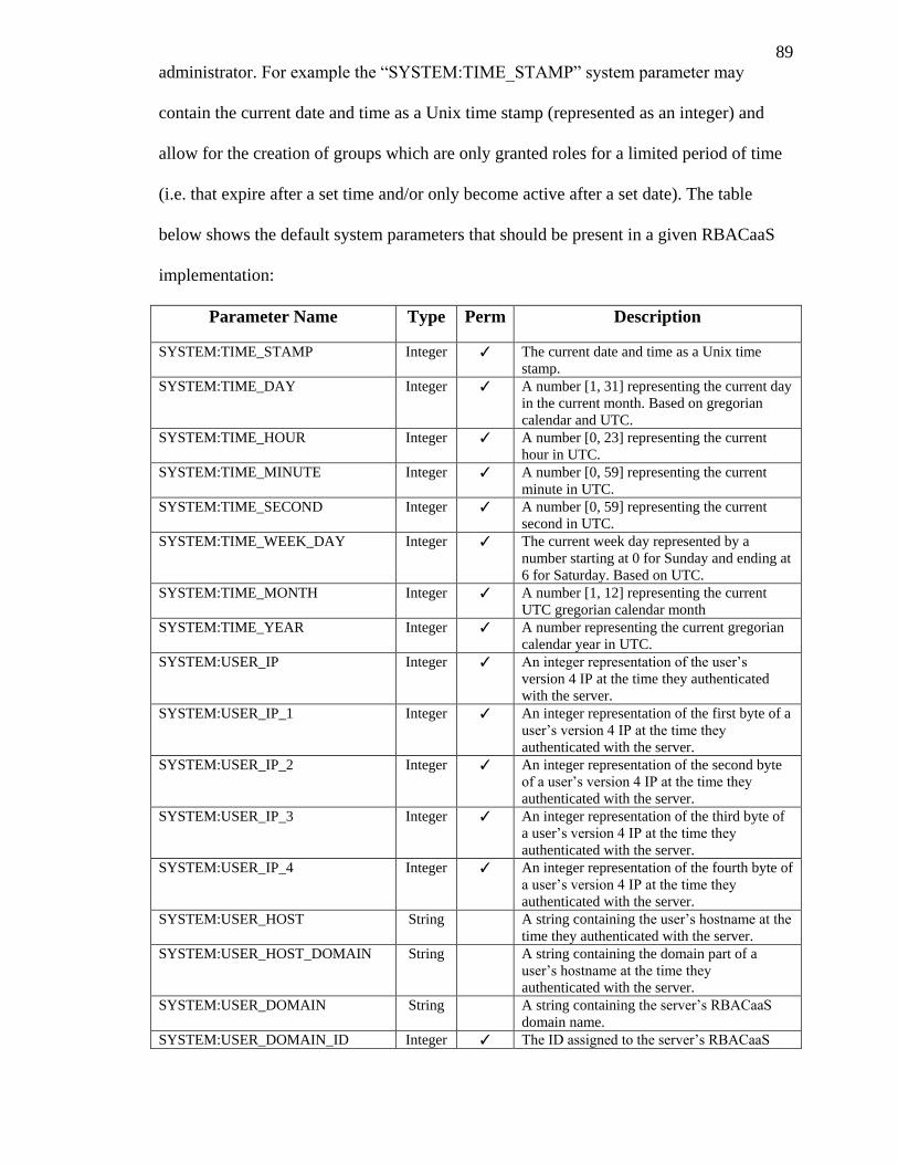
89
administrator. For example the “SYSTEM:TIME_STAMP” system parameter may
contain the current date and time as a Unix time stamp (represented as an integer) and
allow for the creation of groups which are only granted roles for a limited period of time
(i.e. that expire after a set time and/or only become active after a set date). The table
below shows the default system parameters that should be present in a given RBACaaS
implementation:
Parameter Name Type Perm Description
SYSTEM:TIME_STAMP Integer ✓ The current date and time as a Unix time
stamp.
SYSTEM:TIME_DAY Integer ✓ A number [1, 31] representing the current day
in the current month. Based on gregorian
calendar and UTC.
SYSTEM:TIME_HOUR Integer ✓ A number [0, 23] representing the current
hour in UTC.
SYSTEM:TIME_MINUTE Integer ✓ A number [0, 59] representing the current
minute in UTC.
SYSTEM:TIME_SECOND Integer ✓ A number [0, 59] representing the current
second in UTC.
SYSTEM:TIME_WEEK_DAY Integer ✓ The current week day represented by a
number starting at 0 for Sunday and ending at
6 for Saturday. Based on UTC.
SYSTEM:TIME_MONTH Integer ✓ A number [1, 12] representing the current
UTC gregorian calendar month
SYSTEM:TIME_YEAR Integer ✓ A number representing the current gregorian
calendar year in UTC.
SYSTEM:USER_IP Integer ✓ An integer representation of the user’s
version 4 IP at the time they authenticated
with the server.
SYSTEM:USER_IP_1 Integer ✓ An integer representation of the first byte of a
user’s version 4 IP at the time they
authenticated with the server.
SYSTEM:USER_IP_2 Integer ✓ An integer representation of the second byte
of a user’s version 4 IP at the time they
authenticated with the server.
SYSTEM:USER_IP_3 Integer ✓ An integer representation of the third byte of
a user’s version 4 IP at the time they
authenticated with the server.
SYSTEM:USER_IP_4 Integer ✓ An integer representation of the fourth byte of
a user’s version 4 IP at the time they
authenticated with the server.
SYSTEM:USER_HOST String A string containing the user’s hostname at the
time they authenticated with the server.
SYSTEM:USER_HOST_DOMAIN String A string containing the domain part of a
user’s hostname at the time they
authenticated with the server.
SYSTEM:USER_DOMAIN String A string containing the server’s RBACaaS
domain name.
SYSTEM:USER_DOMAIN_ID Integer ✓ The ID assigned to the server’s RBACaaS
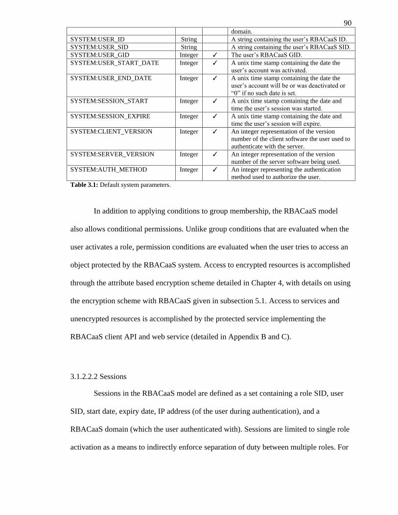
90 domain.
SYSTEM:USER_ID String A string containing the user’s RBACaaS ID.
SYSTEM:USER_SID String A string containing the user’s RBACaaS SID.
SYSTEM:USER_GID Integer ✓ The user’s RBACaaS GID.
SYSTEM:USER_START_DATE Integer ✓ A unix time stamp containing the date the
user’s account was activated.
SYSTEM:USER_END_DATE Integer ✓ A unix time stamp containing the date the
user’s account will be or was deactivated or
“0” if no such date is set.
SYSTEM:SESSION_START Integer ✓ A unix time stamp containing the date and
time the user’s session was started.
SYSTEM:SESSION_EXPIRE Integer ✓ A unix time stamp containing the date and
time the user’s session will expire.
SYSTEM:CLIENT_VERSION Integer ✓ An integer representation of the version
number of the client software the user used to
authenticate with the server.
SYSTEM:SERVER_VERSION Integer ✓ An integer representation of the version
number of the server software being used.
SYSTEM:AUTH_METHOD Integer ✓ An integer representing the authentication
method used to authorize the user.
Table 3.1: Default system parameters.
In addition to applying conditions to group membership, the RBACaaS model
also allows conditional permissions. Unlike group conditions that are evaluated when the
user activates a role, permission conditions are evaluated when the user tries to access an
object protected by the RBACaaS system. Access to encrypted resources is accomplished
through the attribute based encryption scheme detailed in Chapter 4, with details on using
the encryption scheme with RBACaaS given in subsection 5.1. Access to services and
unencrypted resources is accomplished by the protected service implementing the
RBACaaS client API and web service (detailed in Appendix B and C).
3.1.2.2.2 Sessions
Sessions in the RBACaaS model are defined as a set containing a role SID, user
SID, start date, expiry date, IP address (of the user during authentication), and a
RBACaaS domain (which the user authenticated with). Sessions are limited to single role
activation as a means to indirectly enforce separation of duty between multiple roles. For
91
example, if there existed some protected object which required permissions A and B to
access, and role 1 granted a user permission A, and role 2 granted a user permission B, a
user assigned to both roles 1 and 2 could access the object if they were allowed to
activate both roles simultaneously which is likely not the intention of the RBAC
administrator. While this issue may be solved to a degree with a dynamic separation of
duty system (such as the one described in the NIST model), it requires additional work by
RBAC administrators to enforce and provides little benefit to end users. As an
alternative, users may start multiple sessions containing different roles but may not
combine their permissions (i.e. the user in the last example could not access the projected
object but they would still have access to objects only protected with permissions A or B
but not both). Only allowing single role activation also helps enforce the principle of least
privilege; rather than activating multiple or all available roles simultaneously users may
start in their least privileged role and only activate higher roles when the privilege is
required.
Sessions are granted by RBACaaS authentication services to users in the same
domain upon presenting credentials and role activation. The authentication service issues
an auth token (as described in section 3.2) which contains the session set, the set of
permissions the role grants, and a digital signature ensuring it was issued by the stated
RBACaaS server. The authtoken is then used to authenticate with and share the session
with remote services for the stated role and permission set in accordance with the RBSSO
protocol (section 3.2).
92
3.1.2.2.3 Constraints
In addition to the separation of duty protection provided by signal role activation,
the RBACaaS model also provides tools for enforcing a static separation of duty (SSD)
constraint on what roles a user may be granted. RBAC administrators may create
constraints on a set of roles, limiting each user in the system to only holding at most a
fixed number of roles in the constraint set. SSD constraints are enforced at the time of
role assignment and include roles gained through group membership.
3.1.2.2.4 Negative Permissions and Roles
RBACaaS has limited support for negative permissions and roles. Negative
permissions allow RBAC administrators to remove permissions from roles that would
otherwise be inherited from a parent role. This allows for simplified role administration
as administrators may create roles which have the same permissions as an existing role
(by inheriting it) but with some set of permissions removed. Similarly, negative roles
allow for the removal of roles from a user group that would otherwise be inherited from a
parent group.
3.1.2.2.5 Revocation
While the RBACaaS authentication service for each domain keeps an updated
database of users and the required credentials to authenticate them, the distributed nature
of the system would still allow an active session to be used until the expiry date is met.
As it may be required for sessions to be terminated sooner when sensitive data is
involved, a revocation list is provided to list sessions which have become invalidated.
This is accomplished through each domain publishing a public list of active session IDs
93
which correspond to sessions which should be treated as expired (despite not yet reaching
the expiry date). The revocation of user’s attribute encryption keys is a more complex
issue detailed in section 4.3.2.9; more details on user sessions are given in section 3.2.
3.1.2.2.6 Distributed Function
To provide scalable RBAC services to remote systems and to allow for multiple
parties to control their own user credentials and access rights, the RBACaaS system uses
multiple distributed components. These components include the domain authentication
service, the domain RBAC service, the domain administrative service, RBAC clients, and
the user clients. Each organization or party with an independent set of users, services and
resources they wish to protect is considered to be a unique “domain” within the system.
For example, in a system for sharing health records a single hospital may be considered a
domain, as would a doctor’s office, clinic or research group. Every domain is assigned a
unique numeric ID and name string (as detailed in Figure 3.10 and normally
corresponding to the hostname of the domains RBAC service) at the time of creation (the
initial setup of the domain’s authentication and RBAC services).
Authentication Service
Each domain operates at least one authentication service that is responsible for
managing user records, credentials and user authentication within that domain. Each
authentication service handles user authentication requests (with the RBSSO protocol
detailed in section 3.2.2) based on matching user’s presented credentials with existing
user records in an organization’s database. The only requirements imposed by the
authentication service on the underlining user database is that each user be assigned a
94
unique numeric ID and RBAC URI (as detailed in Figure 3.10) within the domain. Upon
receiving a request for user authentication and role activation, the service first validates
the user’s credentials, and then connects to the domain’s RBAC service to verify that the
user possesses access to that role (and that all conditions are met if the role is available
only through a group) and retrieve the set of all permissions the role grants the user and
their conditions, as well as the set of the user’s parameters and their values. Finally, if all
group conditions and verifications are met the service starts a user session by issuing the
user an “auth token” containing the list of permissions, the list of parameters and a
DMACPSABE key (section 4.3).
Multiple authentication services may be run within the same domain to ensure
scalability and reliability so long as the underlining user database used is properly
synchronized within the domain (e.g. MySQL master/slave setup where services read
from different slaves and writes are only done to the master) or the same database is used
for all service instances.
RBAC Service
The RBAC service is a web service that provides the core RBAC operations for a
given domain in an RBACaaS system. The RBAC service stores the RBACaaS model
(Figure 3.6) data being used for the domain (i.e. roles, groups, conditions, permissions,
sessions, SSD constraints, user parameters and their maps to each other and users of the
domain) and responds to requests from both the domain’s authentication service and
systems implementing the RBACaaS API for protecting a resource, service or other
object. RBAC services are also responsible for requesting information from and
responding to requests from other domain’s RBAC services, for example each RBAC
service contains a mapping of parameter and permission RBAC URIs to DMACPSABE
95
attribute names (see section 4.3 and 4.3.2.8) that is made available to other RBAC
services upon request.
RBAC services are linked together in a hierarchical method similar to that used
by the Domain Name System (DNS). Each RBAC service may have a parent for which it
may extend any roles, groups or permissions (by creating new roles, groups, etc. which
inherit a role, group, etc. owned by the parent RBAC service) and assign users to groups,
roles and parameters owned by both itself and its ancestors. Similarly, each service may
also have 0 or more child services. Each domain may have multiple RBAC services (to
balance load, and increase readability) so long as they all descend from a signal RBAC
service also within that domain (as show in Figure 3.12). Each service keeps a list of
approved children that will receive notifications when an update is made to any RBAC
element and the permission and role cache need updating. Child RBAC services may also
directly request a listing of RBAC elements in their relations from their parent as well as
their parent’s ancestors.
For more details on the interface provided by RBAC services see Appendix B.
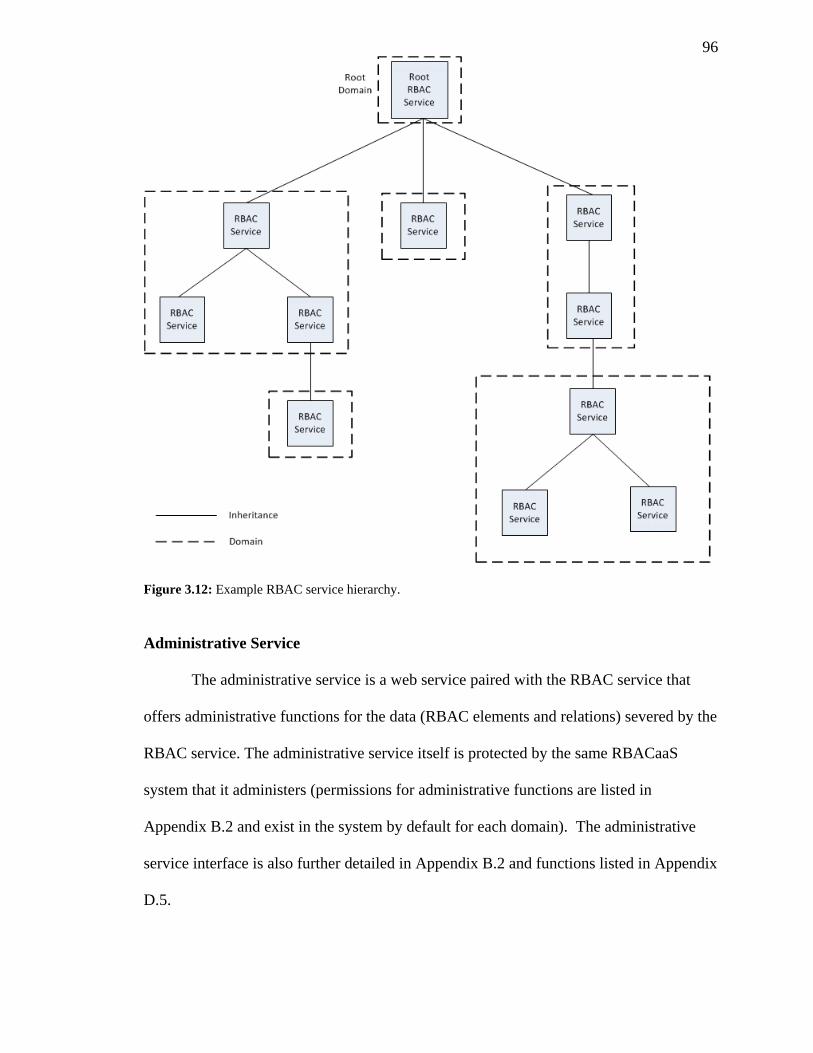
96
Figure 3.12: Example RBAC service hierarchy.
Administrative Service
The administrative service is a web service paired with the RBAC service that
offers administrative functions for the data (RBAC elements and relations) severed by the
RBAC service. The administrative service itself is protected by the same RBACaaS
system that it administers (permissions for administrative functions are listed in
Appendix B.2 and exist in the system by default for each domain). The administrative
service interface is also further detailed in Appendix B.2 and functions listed in Appendix
D.5.
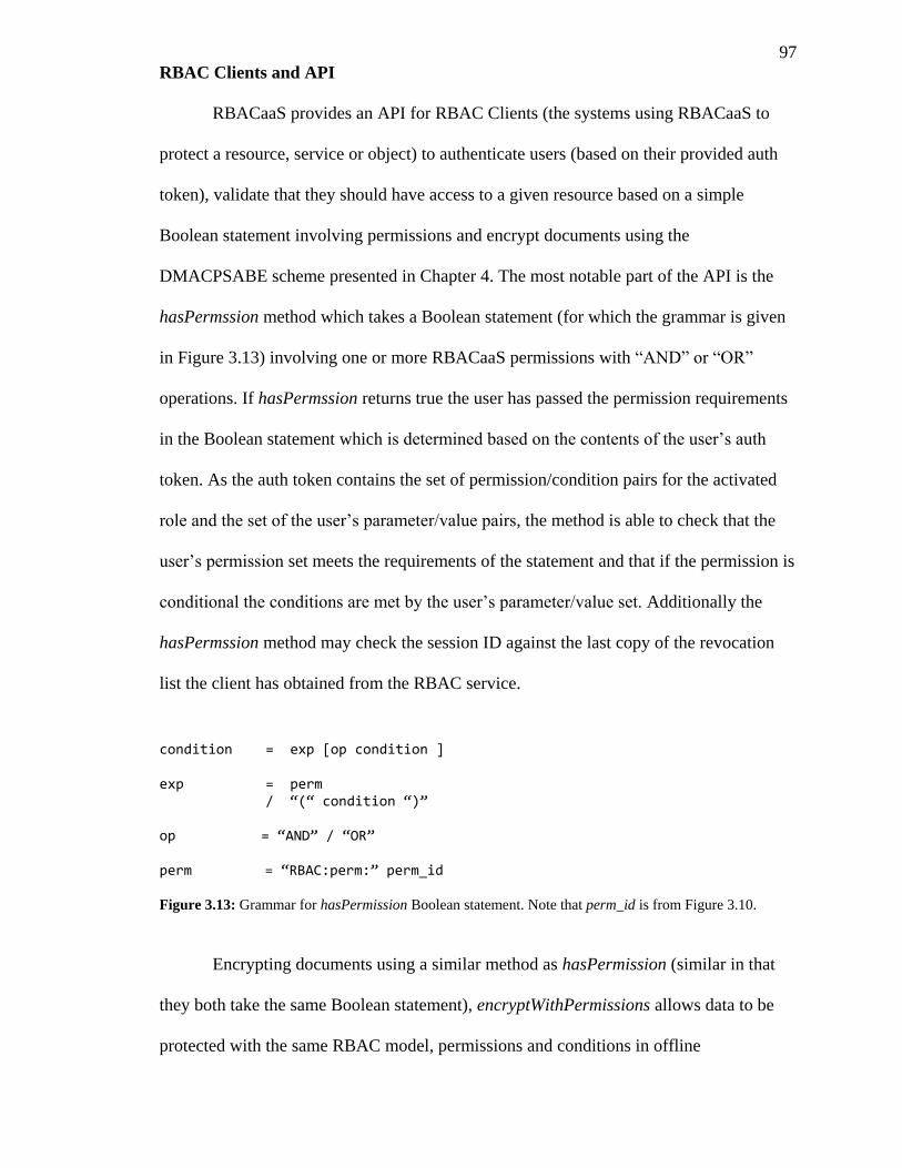
97
RBAC Clients and API
RBACaaS provides an API for RBAC Clients (the systems using RBACaaS to
protect a resource, service or object) to authenticate users (based on their provided auth
token), validate that they should have access to a given resource based on a simple
Boolean statement involving permissions and encrypt documents using the
DMACPSABE scheme presented in Chapter 4. The most notable part of the API is the
hasPermssion method which takes a Boolean statement (for which the grammar is given
in Figure 3.13) involving one or more RBACaaS permissions with “AND” or “OR”
operations. If hasPermssion returns true the user has passed the permission requirements
in the Boolean statement which is determined based on the contents of the user’s auth
token. As the auth token contains the set of permission/condition pairs for the activated
role and the set of the user’s parameter/value pairs, the method is able to check that the
user’s permission set meets the requirements of the statement and that if the permission is
conditional the conditions are met by the user’s parameter/value set. Additionally the
hasPermssion method may check the session ID against the last copy of the revocation
list the client has obtained from the RBAC service.
condition = exp [op condition ] exp = perm / “(“ condition “)” op = “AND” / “OR” perm = “RBAC:perm:” perm_id Figure 3.13: Grammar for hasPermission Boolean statement. Note that perm_id is from Figure 3.10.
Encrypting documents using a similar method as hasPermission (similar in that
they both take the same Boolean statement), encryptWithPermissions allows data to be
protected with the same RBAC model, permissions and conditions in offline
98
environments which may be isolated from the RBAC service for long periods of time or
even indefinitely. Rather than an active service which handles user authentication, the
access policy is embedded in the ciphertext and only decryptable once the user is given
the proper “attributes” in their DMACPSABE key which meet access policy (this is
accomplished with the ciphertext policy attribute based encryption scheme presented in
chapter 4 and details for its use and integration with RBACaaS are given in section 5.1).
The encryptWithPermissions function is responsible for translating the given Boolean
statement using permissions into a proper DMACPSABE access policy using attribute
names (which may require a request to the RBAC service to lookup). Additional details
on the Client API are given in Appendix C.
3.1.2.2.7 Web Service Interfaces, Client API and Formal Description
Appendix B details the RBAC web service and administrative interfaces for
RBACaaS. Appendix C gives details on the client API services use to enable RBACaaS
access controls. Appendix D gives a simplified formal description of the RBACaaS
model which omits the distributed function.
3.1.2.2.8 Permissions Set and Role List Caching
As the model in Figure 3.6 has multiple many-to-many relations between RBAC
elements, several performance improvements are required to make the model useable and
scalable. The first of these improvements is the permissions set cache (pset), which stores
an updated set of permissions/condition pairs calculated using comp_role_pset (see
Appendix D.4) when there has been an update to a role. The pset cache allows for a quick
look up of permissions for a given role and their corresponding conditions during role
99
activation and the creation of an auth token. The second cache based improvement is the
role list cache (rset), which stores an updated set of role/condition pairs, calculated using
comp_group_roles (see Appendix D.4) when there has been an update to a group. The
rset cache allows for quick look ups of roles granted by a group and the conditions that
must be met for them to be activated by a user.
3.1.2.2.9 Example Use Case
This section introduces a health care related use case for intrahospital EHR
protection using the RBACaaS system. In this case it is assumed that all initialization and
setup steps have been performed (e.g. creation of user credentials, set of the RBAC and
authentication services, DMACPSABE authority and master key generation, etc.) and the
health records in question have already been created with the policy stated in the case.
Intrahospital Protection of EHRs
For this case we assume a simplified view of a hospital which is divided into three
departments; medical (consisting of doctors seeing patients), lab (consisting of lab techs
doing work ordered by doctors) and billing/insurance (consisting of accounting clerks
processing insurance claims, sending invoices to patients, etc.). The goal is to provide
doctors in the medical department with access to all medical information in a given EHR
(including lab results) while limiting their access to insurance and billing information; to
allow lab technicians in the lab department to only view lab related parts of an EHR and
no identifying information, billing information or unneeded medical information, and to
allow accounting clerks to only view billing and insurance related information.
Additionally, we want to restrict the clerks to only accessing records during business
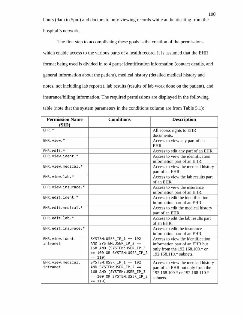
100
hours (9am to 5pm) and doctors to only viewing records while authenticating from the
hospital’s network.
The first step to accomplishing these goals is the creation of the permissions
which enable access to the various parts of a health record. It is assumed that the EHR
format being used is divided in to 4 parts: identification information (contact details, and
general information about the patient), medical history (detailed medical history and
notes, not including lab reports), lab results (results of lab work done on the patient), and
insurance/billing information. The required permissions are displayed in the following
table (note that the system parameters in the conditions column are from Table 5.1):
Permission Name
(SID)
Conditions Description
EHR.* All access rights to EHR
documents. EHR.view.* Access to view any part of an
EHR. EHR.edit.* Access to edit any part of an EHR. EHR.view.ident.* Access to view the identification
information part of an EHR. EHR.view.medical.* Access to view the medical history
part of an EHR. EHR.view.lab.* Access to view the lab results part
of an EHR. EHR.view.insurace.* Access to view the insurance
information part of an EHR. EHR.edit.ident.* Access to edit the identification
information part of an EHR. EHR.edit.medical.* Access to edit the medical history
part of an EHR. EHR.edit.lab.* Access to edit the lab results part
of an EHR. EHR.edit.insurace.* Access to edit the insurance
information part of an EHR. EHR.view.ident. intranet
SYSTEM:USER_IP_1 == 192 AND SYSTEM:USER_IP_2 == 168 AND (SYSTEM:USER_IP_3 == 100 OR SYSTEM:USER_IP_3 == 110)
Access to view the identification
information part of an EHR but
only from the 192.168.100.* or
192.168.110.* subnets.
EHR.view.medical. intranet
SYSTEM:USER_IP_1 == 192 AND SYSTEM:USER_IP_2 == 168 AND (SYSTEM:USER_IP_3 == 100 OR SYSTEM:USER_IP_3 == 110)
Access to view the medical history
part of an EHR but only from the
192.168.100.* or 192.168.110.*
subnets.
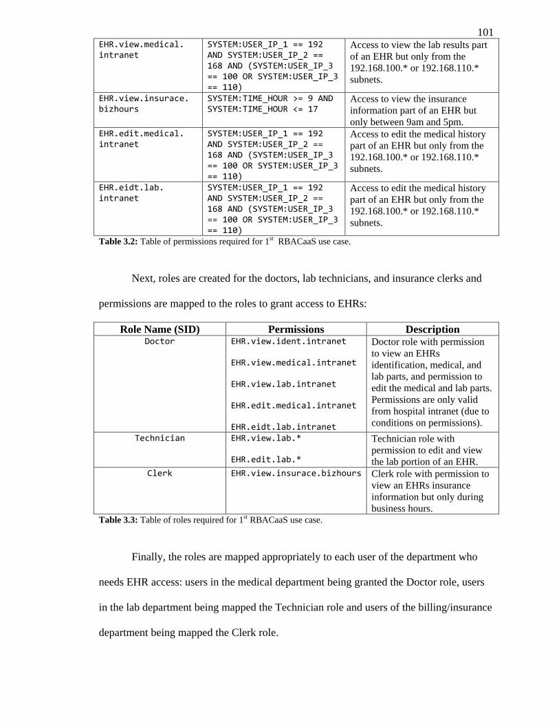
101 EHR.view.medical. intranet
SYSTEM:USER_IP_1 == 192 AND SYSTEM:USER_IP_2 == 168 AND (SYSTEM:USER_IP_3 == 100 OR SYSTEM:USER_IP_3 == 110)
Access to view the lab results part
of an EHR but only from the
192.168.100.* or 192.168.110.*
subnets.
EHR.view.insurace. bizhours
SYSTEM:TIME_HOUR >= 9 AND SYSTEM:TIME_HOUR <= 17
Access to view the insurance
information part of an EHR but
only between 9am and 5pm. EHR.edit.medical. intranet
SYSTEM:USER_IP_1 == 192 AND SYSTEM:USER_IP_2 == 168 AND (SYSTEM:USER_IP_3 == 100 OR SYSTEM:USER_IP_3 == 110)
Access to edit the medical history
part of an EHR but only from the
192.168.100.* or 192.168.110.*
subnets.
EHR.eidt.lab. intranet
SYSTEM:USER_IP_1 == 192 AND SYSTEM:USER_IP_2 == 168 AND (SYSTEM:USER_IP_3 == 100 OR SYSTEM:USER_IP_3 == 110)
Access to edit the medical history
part of an EHR but only from the
192.168.100.* or 192.168.110.*
subnets.
Table 3.2: Table of permissions required for 1st RBACaaS use case.
Next, roles are created for the doctors, lab technicians, and insurance clerks and
permissions are mapped to the roles to grant access to EHRs:
Role Name (SID) Permissions Description Doctor EHR.view.ident.intranet
EHR.view.medical.intranet EHR.view.lab.intranet EHR.edit.medical.intranet EHR.eidt.lab.intranet
Doctor role with permission
to view an EHRs
identification, medical, and
lab parts, and permission to
edit the medical and lab parts.
Permissions are only valid
from hospital intranet (due to
conditions on permissions).
Technician EHR.view.lab.* EHR.edit.lab.*
Technician role with
permission to edit and view
the lab portion of an EHR. Clerk EHR.view.insurace.bizhours Clerk role with permission to
view an EHRs insurance
information but only during
business hours. Table 3.3: Table of roles required for 1st RBACaaS use case.
Finally, the roles are mapped appropriately to each user of the department who
needs EHR access: users in the medical department being granted the Doctor role, users
in the lab department being mapped the Technician role and users of the billing/insurance
department being mapped the Clerk role.
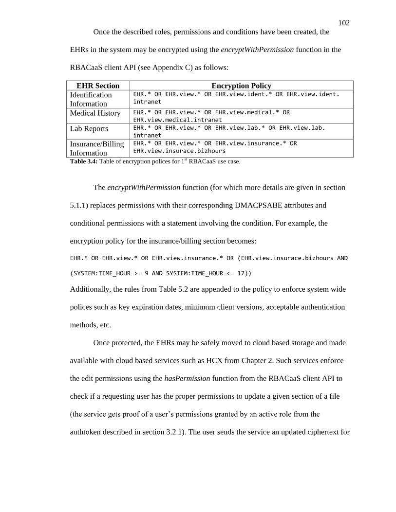
102
Once the described roles, permissions and conditions have been created, the
EHRs in the system may be encrypted using the encryptWithPermission function in the
RBACaaS client API (see Appendix C) as follows:
EHR Section Encryption Policy
Identification
Information
EHR.* OR EHR.view.* OR EHR.view.ident.* OR EHR.view.ident. intranet
Medical History EHR.* OR EHR.view.* OR EHR.view.medical.* OR EHR.view.medical.intranet
Lab Reports EHR.* OR EHR.view.* OR EHR.view.lab.* OR EHR.view.lab. intranet
Insurance/Billing
Information
EHR.* OR EHR.view.* OR EHR.view.insurance.* OR EHR.view.insurace.bizhours
Table 3.4: Table of encryption polices for 1st RBACaaS use case.
The encryptWithPermission function (for which more details are given in section
5.1.1) replaces permissions with their corresponding DMACPSABE attributes and
conditional permissions with a statement involving the condition. For example, the
encryption policy for the insurance/billing section becomes:
EHR.* OR EHR.view.* OR EHR.view.insurance.* OR (EHR.view.insurace.bizhours AND
(SYSTEM:TIME_HOUR >= 9 AND SYSTEM:TIME_HOUR <= 17))
Additionally, the rules from Table 5.2 are appended to the policy to enforce system wide
polices such as key expiration dates, minimum client versions, acceptable authentication
methods, etc.
Once protected, the EHRs may be safely moved to cloud based storage and made
available with cloud based services such as HCX from Chapter 2. Such services enforce
the edit permissions using the hasPermission function from the RBACaaS client API to
check if a requesting user has the proper permissions to update a given section of a file
(the service gets proof of a user’s permissions granted by an active role from the
authtoken described in section 3.2.1). The user sends the service an updated ciphertext for
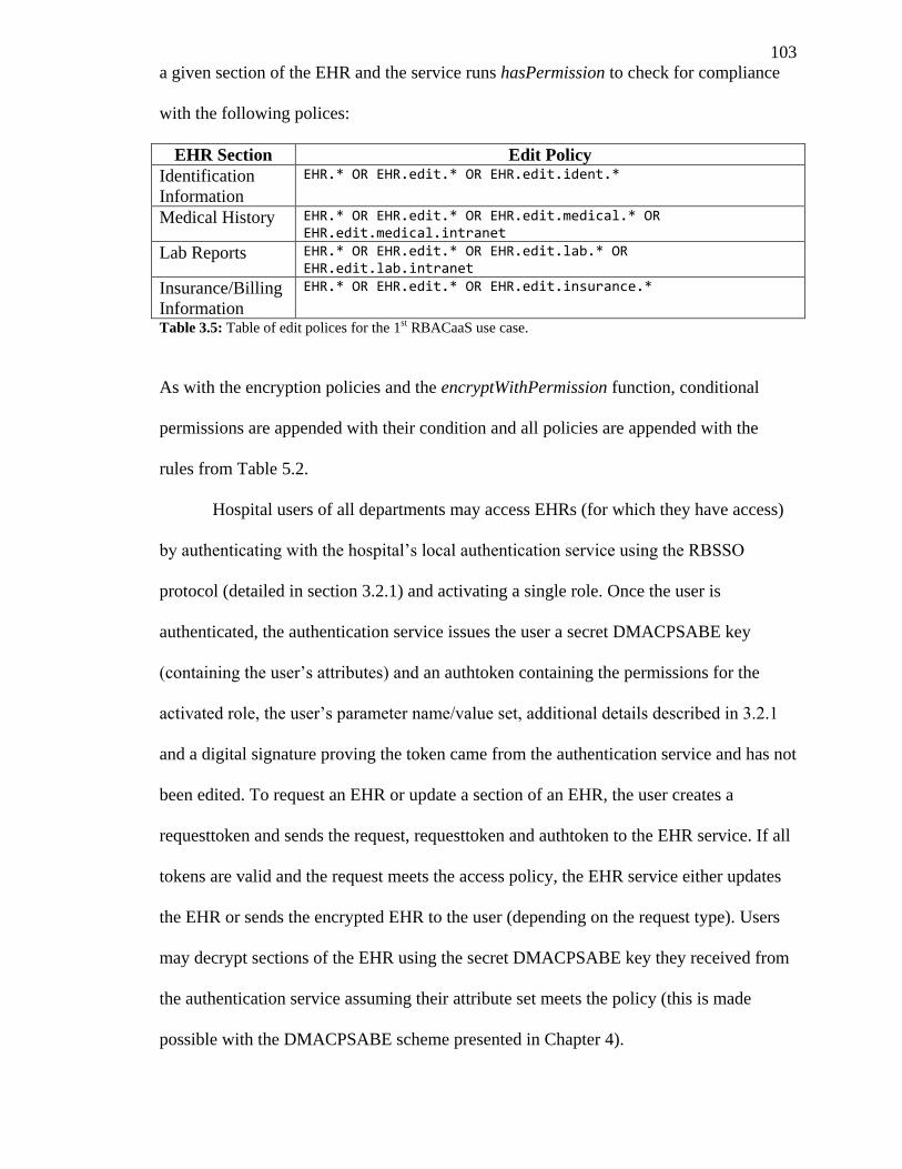
103
a given section of the EHR and the service runs hasPermission to check for compliance
with the following polices:
EHR Section Edit Policy
Identification
Information
EHR.* OR EHR.edit.* OR EHR.edit.ident.*
Medical History EHR.* OR EHR.edit.* OR EHR.edit.medical.* OR EHR.edit.medical.intranet
Lab Reports EHR.* OR EHR.edit.* OR EHR.edit.lab.* OR EHR.edit.lab.intranet
Insurance/Billing
Information
EHR.* OR EHR.edit.* OR EHR.edit.insurance.*
Table 3.5: Table of edit polices for the 1st RBACaaS use case.
As with the encryption policies and the encryptWithPermission function, conditional
permissions are appended with their condition and all policies are appended with the
rules from Table 5.2.
Hospital users of all departments may access EHRs (for which they have access)
by authenticating with the hospital’s local authentication service using the RBSSO
protocol (detailed in section 3.2.1) and activating a single role. Once the user is
authenticated, the authentication service issues the user a secret DMACPSABE key
(containing the user’s attributes) and an authtoken containing the permissions for the
activated role, the user’s parameter name/value set, additional details described in 3.2.1
and a digital signature proving the token came from the authentication service and has not
been edited. To request an EHR or update a section of an EHR, the user creates a
requesttoken and sends the request, requesttoken and authtoken to the EHR service. If all
tokens are valid and the request meets the access policy, the EHR service either updates
the EHR or sends the encrypted EHR to the user (depending on the request type). Users
may decrypt sections of the EHR using the secret DMACPSABE key they received from
the authentication service assuming their attribute set meets the policy (this is made
possible with the DMACPSABE scheme presented in Chapter 4).
104
3.2 Single Sign On
A critical component for a distributed authentication system not covered by our
RBAC as a Service model is the protocol and mechanism by which user sessions are
authorized and securely propagated to remote services. Centralizing this task as a single
authentication server or role server would create new bottle necks in the system and limit
the scalability gain from using a distributed model. To solve issues relating to sessions in
our disturbed RBAC model we have created an accompanying Single Sign On (SSO)
model, protocol and prototype called Role Based Single Sign On (RBSSO).
3.2.1 RBSSO Description
The RBSSO protocol attempts to accomplish the following goals in its design:
1. Distributed: a SSO system for the cloud should ideally be distributed rather than
centralized to match the distributed computing potential of most cloud computing
infrastructure. The systems overall functionality should be unaffected by nodes
coming and going on/offline at random intervals and scaled by simply adding
additional nodes. No or few centralized points of failure should be present in the
system.
2. Isolated: User credentials and personal details should be isolated from the public
and potently untrustworthy cloud. Cloud based services should only be granted
the minimum amount of information to authenticate a user and grant access to a
service.
3. Scalable: The SSO system should be scalable simply by adding additional nodes
to a public or private cloud. Costly operations such as communications between
105
virtual cloud resources and between users and cloud resources should be
minimized to prevent network bottle necks.
4. Secure: The SSO system should be secure enough to comply with data privacy
laws such as PIPEDA, HIPA and HIPAA, as well as provide a reasonable level of
assurance to users that their accounts are secure even when operating on a public
cloud.
5. Convenient: The system should provide maximum convenience and usability to
both the systems users and administrators. E.g. not requiring user to sign in to
each cloud based service individually.
6. Compatibility: Be compatible with most common cloud computing infrastructure
(i.e. Amazon web services and Eucalyptus) and take full advantage of the
RBACaaS mode described before.
The RBSSO model defines the following major components necessary for client
single sign on authentication with cloud based services:
1. Authentication Servers (AuthServers): Servers or nodes which handle user
authentication requests and issue AuthTokens. AuthServers are hosted on the
trusted network for an organization who wishes to access cloud services.
2. RBAC Service: RBACaaS RBAC service which stores the roles and relations for
the RBACaaS system. May be combined with an AuthServer.
3. Cloud Based Services: Services offered on a potentially untrusted cloud and
service clients of the RBACaaS system wishing to secure a resource.
4. Service Controllers: Systems located on a trusted network that are responsible
for spawning new machine instances on an untrusted cloud which run cloud base
services and initialize them with their initial data.
106
5. End User Clients: Clients of the system and their software and hardware
components.
3.2.1.1 Authentication Servers
To distribute the load of user authentication, isolate user credentials to their
organization and trusted network and keep administration of user accounts within an
organization authority, authentication servers are distributed among the organizations that
require access to the publicly hosted cloud based services and run on the organization’s
presumably trusted network. Using this model, organizations are made responsible for
their own user accounts and the scalability of their authentication services. For example,
if a set of cloud based services were created to share electronic health records between
hospital, clinics, doctors’ offices and emergency medical services, each would host their
own authentication server on their own network (see Figure 3.14).
Before use, Authentication Servers are first initialized with two public/private key
pairs, (AKsigpub, AKsigpri) and (AKencpub, AKencpri) which they will use through the
future course of their operation. Also before use, the keys AKsigpub and AKencpub must
be registered with the Service Controller network as a trusted AuthServer through a
secure channel. The key pair (AKsigpub, AKsigpri) is used for signing user AuthTokens
while the pair (AKencpub, AKencpri) is used as part of the encrypted communications
with the client during an AuthRequest. Before authenticating with an AuthServer, clients
must first obtain the keys AKsigpub and AKencpub from the service controller network.
Once initialized, both the AuthServer and Client need not perform these steps again
unless the AuthServer’s keypairs are compromised and revoked.
Authentication servers may serve as a front end to existing credential stores for an
organization (e.g. LDAP, Kerberos, MySQL database, etc.) to provide authentication
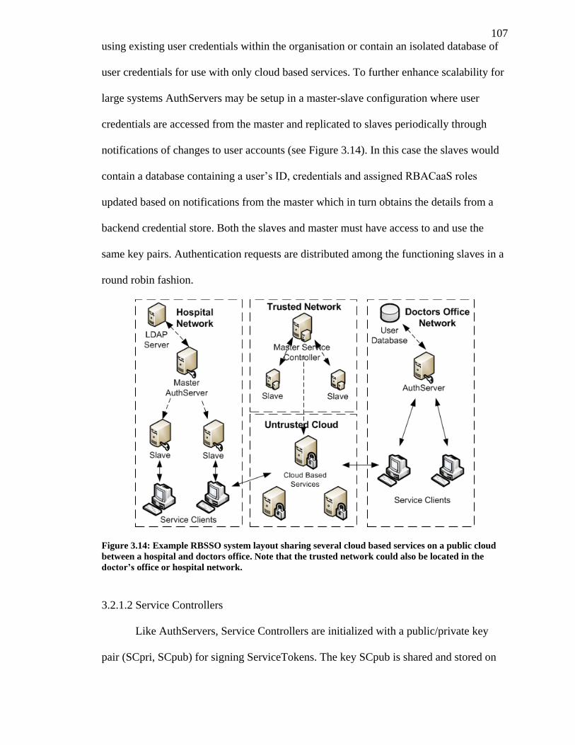
107
using existing user credentials within the organisation or contain an isolated database of
user credentials for use with only cloud based services. To further enhance scalability for
large systems AuthServers may be setup in a master-slave configuration where user
credentials are accessed from the master and replicated to slaves periodically through
notifications of changes to user accounts (see Figure 3.14). In this case the slaves would
contain a database containing a user’s ID, credentials and assigned RBACaaS roles
updated based on notifications from the master which in turn obtains the details from a
backend credential store. Both the slaves and master must have access to and use the
same key pairs. Authentication requests are distributed among the functioning slaves in a
round robin fashion.
Figure 3.14: Example RBSSO system layout sharing several cloud based services on a public cloud
between a hospital and doctors office. Note that the trusted network could also be located in the
doctor’s office or hospital network.
3.2.1.2 Service Controllers
Like AuthServers, Service Controllers are initialized with a public/private key
pair (SCpri, SCpub) for signing ServiceTokens. The key SCpub is shared and stored on
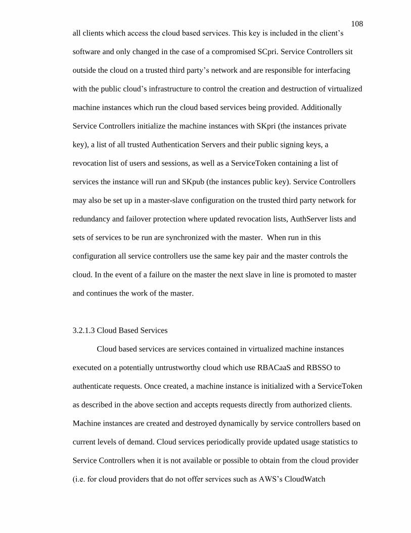
108
all clients which access the cloud based services. This key is included in the client’s
software and only changed in the case of a compromised SCpri. Service Controllers sit
outside the cloud on a trusted third party’s network and are responsible for interfacing
with the public cloud’s infrastructure to control the creation and destruction of virtualized
machine instances which run the cloud based services being provided. Additionally
Service Controllers initialize the machine instances with SKpri (the instances private
key), a list of all trusted Authentication Servers and their public signing keys, a
revocation list of users and sessions, as well as a ServiceToken containing a list of
services the instance will run and SKpub (the instances public key). Service Controllers
may also be set up in a master-slave configuration on the trusted third party network for
redundancy and failover protection where updated revocation lists, AuthServer lists and
sets of services to be run are synchronized with the master. When run in this
configuration all service controllers use the same key pair and the master controls the
cloud. In the event of a failure on the master the next slave in line is promoted to master
and continues the work of the master.
3.2.1.3 Cloud Based Services
Cloud based services are services contained in virtualized machine instances
executed on a potentially untrustworthy cloud which use RBACaaS and RBSSO to
authenticate requests. Once created, a machine instance is initialized with a ServiceToken
as described in the above section and accepts requests directly from authorized clients.
Machine instances are created and destroyed dynamically by service controllers based on
current levels of demand. Cloud services periodically provide updated usage statistics to
Service Controllers when it is not available or possible to obtain from the cloud provider
(i.e. for cloud providers that do not offer services such as AWS’s CloudWatch
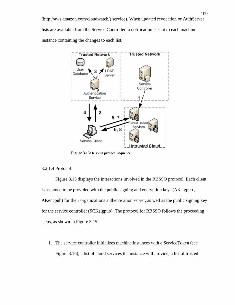
109
(http://aws.amazon.com/cloudwatch/) service). When updated revocation or AuthServer
lists are available from the Service Controller, a notification is sent to each machine
instance containing the changes to each list.
3.2.1.4 Protocol
Figure 3.15 displays the interactions involved in the RBSSO protocol. Each client
is assumed to be provided with the public signing and encryption keys (AKsigpub ,
AKencpub) for their organizations authentication server, as well as the public signing key
for the service controller (SCKsigpub). The protocol for RBSSO follows the proceeding
steps, as shown in Figure 3.15:
1. The service controller initializes machine instances with a ServiceToken (see
Figure 3.16), a list of cloud services the instance will provide, a list of trusted
Figure 3.15: RBSSO protocol sequence.
110
authentication servers and their set of public keys, a list of globally black listed
users and the instances private key, SKpri.
2. The service client authenticates with their organization’s authentication server by
generating a secret key CKsec and an AuthRequest (see Figure 3.17). The
AuthRequest, containing the user’s credentials, the RBACaaS role they wish to
activate and a public client key from the client public/private key pair created
when the client program is initialized, is then transmitted to the authentication
server.
3. The authentication server decrypts the AuthRequest using AKencpri and CKsec,
validates the user’s credentials, and checks that the time stamp and request ID are
acceptable. Credentials may be validated against a local database of user
credentials or existing authentication infrastructure on the same trusted network
(eg. LDAP).
4. The authentication server then makes a request on the domain’s RBAC service to
validate that the user may activate the requested role, obtain the set of
permission/conditions pairs, obtain the set of parameter name/value pairs and start
an RBACaaS session.
5. Once the user is validated, the authentication server issues and signs an
AuthToken (see Figure 3.18), containing the permission and parameter sets, with
AKsigpri for the client’s session with the cloud services. This transmission is
appended with the DMACPSABE (see section 4.3) key for the user’s current
111
attributes and encrypted with CKsec to protect the user’s privacy (i.e. so the user
may not be identified by outside observers).
6. Before the service consumer makes a normal request upon a service it first
extracts the DMACPSABE key from the end of the AuthToken and requests the
service’s ServiceToken from the instance on which it resides. The service
consumer then validates the service controller’s signature using SCKpub and
ensures that the service is listed in the service listing and is connecting from the
stated IP or hostname.
7. The consumer may now authenticate and make a request upon any cloud service
on the instance by generating the secret session key SEKsec and using it to
encrypt its AuthToken, the request and a newly generated RequestToken (see
Figure 3.20) together. SEKsec is appended with a delimiter and random number
and encrypted with SKpub (obtained from the ServiceToken) .The ciphertexts are
appended and transmitted to the service (see Figure 3.19).
8. The service decrypts SEKsec using SKpri and decrypts the request, RequestToken
and AuthToken using SEKsec. The service then proceeds to validate the
signatures contained in AuthToken and RequestToken using AKsigpub and
CKpub (from the AuthToken) and validate the fields they contain (time stamp has
not expired, etc.). If valid, SEKsec and the AuthToken are temporarily stored for
future requests with the instance until the session expires.
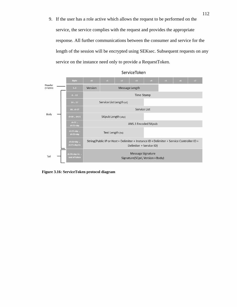
112
9. If the user has a role active which allows the request to be performed on the
service, the service complies with the request and provides the appropriate
response. All further communications between the consumer and service for the
length of the session will be encrypted using SEKsec. Subsequent requests on any
service on the instance need only to provide a RequestToken.
Figure 3.16: ServiceToken protocol diagram
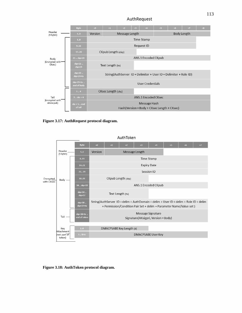
113
Figure 3.17: AuthRequest protocol diagram.
Figure 3.18: AuthToken protocol diagram.
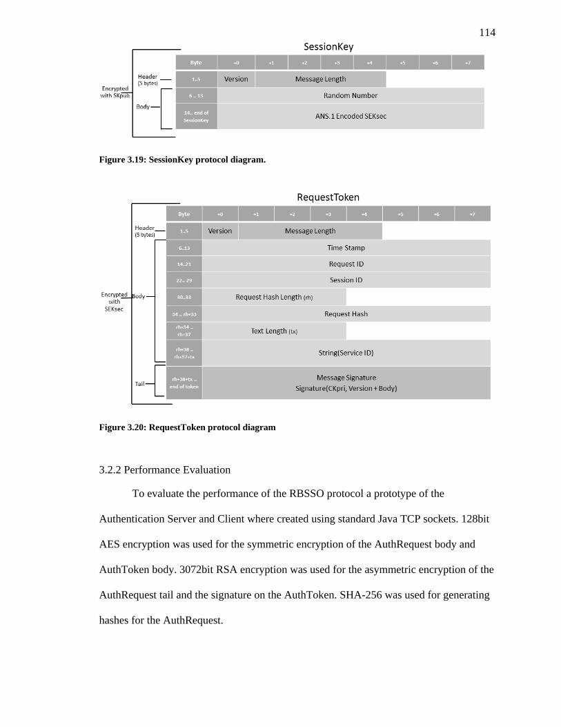
114
Figure 3.19: SessionKey protocol diagram.
Figure 3.20: RequestToken protocol diagram
3.2.2 Performance Evaluation
To evaluate the performance of the RBSSO protocol a prototype of the
Authentication Server and Client where created using standard Java TCP sockets. 128bit
AES encryption was used for the symmetric encryption of the AuthRequest body and
AuthToken body. 3072bit RSA encryption was used for the asymmetric encryption of the
AuthRequest tail and the signature on the AuthToken. SHA-256 was used for generating
hashes for the AuthRequest.
115
Two controls, a simple SSL based connection and Kerberos
(http://web.mit.edu/kerberos/) (a popular SSO system), where tested under the same
conditions for a basis of comparison. For the first control, an authentication server was
created that replaced the encryption of the body and signature of the AuthRequest with an
SSL connection (the tail containing CKsec and the token hash were removed from the
SSL implementation). Secondly the RBSSO protocol was also compared against the
performance of a Java based Kerberos client and the MIT Kerberos 5 implementation
which retrieved a ticket granting ticket and a service ticket (somewhat equivalent to an
AuthToken in RBSSO). The performance of all three protocols (measured in average
time per request) was measured on both a private isolated low latency local area network
and over a higher latency and more noisy wide area connection. Each protocol was tested
with 10,000 authentication requests for each network in sequential runs of 1000 requests.
The results on these tests are shown in Figure 3.21, Figure 3.22 and Figure 3.23.
The RBSSO protocol performed approximately 38% faster on average than the
SSL implementation on the LAN and 66% faster over the WAN connection. This is
likely a result of the decreased number of requests involved in the RBSSO protocol (no
handshake is required and only a single request is made containing the AuthRequest) and
explains the difference between the LAN and WAN connections (the cost per request
being higher on the connection with increased latency). Similarly RBSSO performed
25% faster than Kerberos over an WAN connection but performed 21% slower over a
LAN connection. This is also likely a result of the number of requests, Kerberos requiring
a connection to both to a Kerberos authentication server and a ticket granting server
before it can make a request on a service.
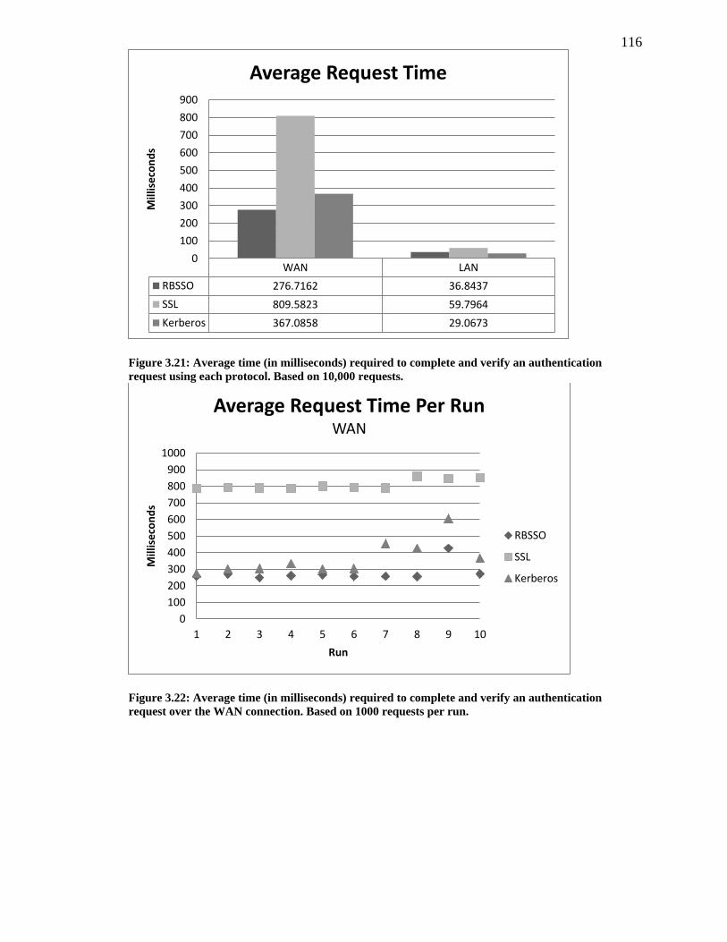
116
Figure 3.21: Average time (in milliseconds) required to complete and verify an authentication
request using each protocol. Based on 10,000 requests.
Figure 3.22: Average time (in milliseconds) required to complete and verify an authentication
request over the WAN connection. Based on 1000 requests per run.
WAN LAN
RBSSO 276.7162 36.8437
SSL 809.5823 59.7964
Kerberos 367.0858 29.0673
0
100
200
300
400
500
600
700
800
900
Mill
ise
con
ds
Average Request Time
0
100
200
300
400
500
600
700
800
900
1000
1 2 3 4 5 6 7 8 9 10
Mill
ise
con
ds
Run
Average Request Time Per Run WAN
RBSSO
SSL
Kerberos
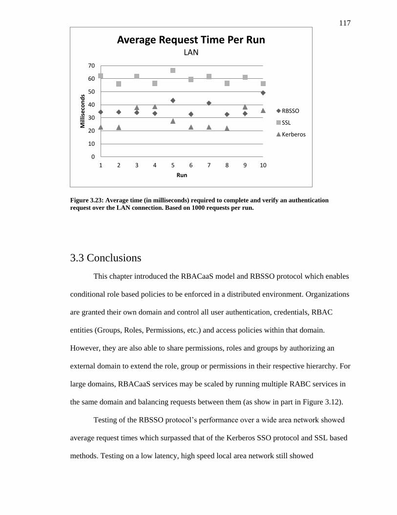
117
Figure 3.23: Average time (in milliseconds) required to complete and verify an authentication
request over the LAN connection. Based on 1000 requests per run.
3.3 Conclusions
This chapter introduced the RBACaaS model and RBSSO protocol which enables
conditional role based policies to be enforced in a distributed environment. Organizations
are granted their own domain and control all user authentication, credentials, RBAC
entities (Groups, Roles, Permissions, etc.) and access policies within that domain.
However, they are also able to share permissions, roles and groups by authorizing an
external domain to extend the role, group or permissions in their respective hierarchy. For
large domains, RBACaaS services may be scaled by running multiple RABC services in
the same domain and balancing requests between them (as show in part in Figure 3.12).
Testing of the RBSSO protocol’s performance over a wide area network showed
average request times which surpassed that of the Kerberos SSO protocol and SSL based
methods. Testing on a low latency, high speed local area network still showed
0
10
20
30
40
50
60
70
1 2 3 4 5 6 7 8 9 10
Mill
ise
con
ds
Run
Average Request Time Per Run LAN
RBSSO
SSL
Kerberos

118
performance gains over the SSL based method and only a minor disadvantage compared
to Kerberos. Additional details on integrating RBACaaS and RBSSO with the HCX
services described in Chapter 2 and the DMACPSAE encryption scheme of Chapter 4 are
given in section 5.1. Future work, new areas of research and possible improvements are
detailed in section 5.2.
119
Chapter 4
4 Cloud Privacy Through Attribute Based
Encryption
4.1 Introduction
4.1.1 Data Privacy on the Cloud
Ensuring data privacy on a potentially untrustworthy public cloud is still one of
the open research problems in cloud computing (Zhang, Cheng, & Boutaba, 2010),
(Armbrust, et al., 2009). Common data privacy methods amounting to “throwing
encryption at the problem” are ineffective on the cloud platform and many current
research efforts require additional trust computing or cryptographic coprocessors
hardware (Itani, Kayssi, & Chehab, 2009), (Chow, et al., 2009) not yet offered by any
public cloud provider.
Traditional public and symmetric key encryption methods quickly run into
problems when an untrusted third party (such as a cloud provider) is given control of all
hardware and network resources, leaving cloud application developers to either use the
cloud purely as a semi-public hard drive for storing encrypted data (losing most
scalability advantages of the cloud and limiting cloud applications to simply retrieving an
encrypted file) or handing over some level of trust and control to the cloud provider to
enable their cloud based applications to process potentially sensitive data. Even when
information on persistent cloud storage (such as the S3 or EBS services offered by
Amazon’s AWS) is encrypted, cloud based applications which process and rely on the
data may be vulnerable when run on hardware or virtual instances operated by an
120
untrustworthy cloud provider. It would be trivial for such a provider to extract sensitive
data (including the encryption keys themselves from a virtual instance’s hard drive,
memory or network connections. Additionally, man-in-the-middle type attacks would be
trivial for the cloud provider as they operate both the network, hardware and IP ranges for
the virtualized services.
This chapter outlines a novel take on attribute encryption for protecting records both
on and off the cloud. Several improvements over traditional ABE schemes are added,
including distributed attribute authorities with shared subsets of attributes. Subsections
4.1.2 and 4.1.3 provide a background on the concepts involved in attribute based
encryption while subsections 4.2 details current research related to attribute based
encryption and cloud privacy. Subsection 4.3 and 4.4 detail our attribute encryption
system, implementation and evaluation, and subsection 4.5 outlines how it may be used
with RBACaaS, RBSSO and HCX.
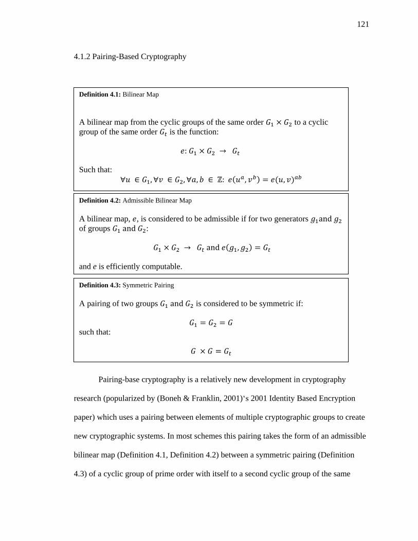
121
4.1.2 Pairing-Based Cryptography
Pairing-base cryptography is a relatively new development in cryptography
research (popularized by (Boneh & Franklin, 2001)‘s 2001 Identity Based Encryption
paper) which uses a pairing between elements of multiple cryptographic groups to create
new cryptographic systems. In most schemes this pairing takes the form of an admissible
bilinear map (Definition 4.1, Definition 4.2) between a symmetric pairing (Definition
4.3) of a cyclic group of prime order with itself to a second cyclic group of the same
( ) ( )
Definition 4.1: Bilinear Map
A bilinear map from the cyclic groups of the same order to a cyclic
group of the same order is the function:
Such that:
( )
Definition 4.2: Admissible Bilinear Map
A bilinear map, , is considered to be admissible if for two generators
of groups :
and e is efficiently computable.
Definition 4.3: Symmetric Pairing
A pairing of two groups is considered to be symmetric if:
such that:
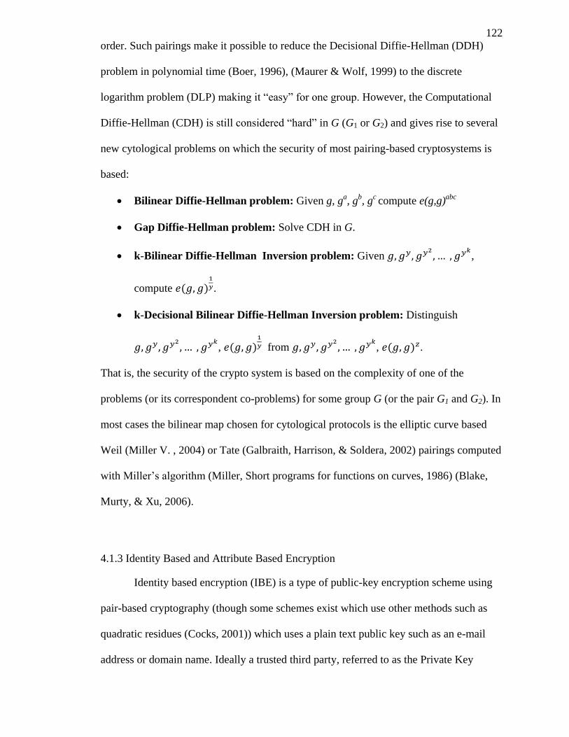
122
order. Such pairings make it possible to reduce the Decisional Diffie-Hellman (DDH)
problem in polynomial time (Boer, 1996), (Maurer & Wolf, 1999) to the discrete
logarithm problem (DLP) making it “easy” for one group. However, the Computational
Diffie-Hellman (CDH) is still considered “hard” in G (G1 or G2) and gives rise to several
new cytological problems on which the security of most pairing-based cryptosystems is
based:
Bilinear Diffie-Hellman problem: Given g, ga, g
b, g
c compute e(g,g)
abc
Gap Diffie-Hellman problem: Solve CDH in G.
k-Bilinear Diffie-Hellman Inversion problem: Given
,
compute ( )
.
k-Decisional Bilinear Diffie-Hellman Inversion problem: Distinguish
, ( )
from
, ( ) .
That is, the security of the crypto system is based on the complexity of one of the
problems (or its correspondent co-problems) for some group G (or the pair G1 and G2). In
most cases the bilinear map chosen for cytological protocols is the elliptic curve based
Weil (Miller V. , 2004) or Tate (Galbraith, Harrison, & Soldera, 2002) pairings computed
with Miller’s algorithm (Miller, Short programs for functions on curves, 1986) (Blake,
Murty, & Xu, 2006).
4.1.3 Identity Based and Attribute Based Encryption
Identity based encryption (IBE) is a type of public-key encryption scheme using
pair-based cryptography (though some schemes exist which use other methods such as
quadratic residues (Cocks, 2001)) which uses a plain text public key such as an e-mail
address or domain name. Ideally a trusted third party, referred to as the Private Key
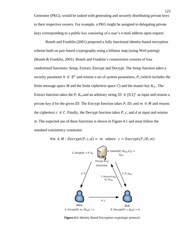
123
Generator (PKG), would be tasked with generating and securely distributing private keys
to their respective owners. For example, a PKG might be assigned to delegating private
keys corresponding to a public key consisting of a user’s e-mail address upon request.
Boneh and Franklin (2001) proposed a fully functional identity-based encryption
scheme built on pair-based cryptography using a bilinear map (using Weil pairing)
(Boneh & Franklin, 2001). Boneh and Franklin’s construction consists of four
randomized functions: Setup, Extract, Encrypt and Decrypt. The Setup function takes a
security parameter and returns a set of system parameters, P, (which includes the
finite message space M and the finite ciphertext space C) and the master key Km . The
Extract function takes the P, Km and an arbitrary string as input and returns a
private key d for the given ID. The Encrypt function takes P, ID, and and returns
the ciphertext . Finally, the Decrypt function takes P, c, and d as input and returns
m. The expected use of these functions is shown in Figure 4.1 and must follow the
standard consistency constraint:
( ) ( )
Figure 4.1: Identity-Based Encryption cryptologic protocol.
124
Like many other pairing-based ciphers, identity-based encryption’s security is
dependent on the “hardness” of the Bilinear Diffie-Hellman Problem and has been proven
semantically secure under the Bilinear Diffie-Hellman assumption (Boneh & Franklin,
2001). Additionally, Boneh and Franklin prove how the technique from Fujiaski and
Okamoto (1999) can be used to convert their construct to provide a chosen ciphertext
secure IBE system in the random oracle model.
Several cryptosystems have been built on the concept of IBE including the
Attribute Based Encryption (ABE) scheme first introduced by Sahai and Waters (2005)
as part of their Fuzzy Identity-Based Encryption cryptosystem (Sahai & Waters, 2005).
ABE allows an entity to encrypt a document such that only users with a specific set of
attributes may decrypt the document. For example, a hospital may wish to limit access to
a document to employees with the set of attributes {“doctor”, “ethics-committee”,
“staff”}. This is made possible through ABE by issuing a private key (their “identity”) to
each employee composed partially of their set of assigned attributes in such a way that
collusion between multiple employees does not grant a key containing a larger or
combined set of attributes. Employees are then limited to decrypting only messages
encrypted with some subset of their attributes. For the cloud, and other untrusted storage
environments, ABE is a significant development as it allows for the enforcement of
access policies via the encryption used on the document rather than the system holding
the documents. Additionally, ABE ensures that documents are protected with the same
access policies and same level of security both on and offline, offering the potential for
documents to be moved seamlessly from an online storage environment (e.g. a cloud
storage service) to an offline storage environment without compromising their security
and still allowing access to users matching the set access policy.
125
Recent research in ABE has led to several improved schemes which enhance the
complexity possible in ABE access policies including; enabling a limited form of role
based access control. Key-Policy Attribute-Based Encryption (KP-ABE) (Goyal, Pandey,
Sahai, & Waters, 2006) enables attribute based policies to be embedded in the user’s
private key, allowing them to decrypt documents encrypted with attributes matching their
key’s policy. Ciphertext-Policy Attribute-Based Encryption (CP-ABE) expands on ABE
to add variable attributes (attributes which may be assigned a value) and access policies
embedded in the cihpertext which support fuzzy Boolean operations including greater
than, less than, less than or equals, and greater than or equals, as well as other Boolean
statements (equals, x of set of Boolean statements are true, AND, OR, etc.). For example,
one user may be assigned the attribute “room = 5020” corresponding to their office
number, while another user “room = 4005” and a document may then be encrypted with
the policy “room > 5000 AND room < 6000” to allow only users on the 5th
floor
(assuming room numbers start with a floor number) to decrypt the document. Expanded
descriptions of these cryptosystems and technical details are provided in the literature
review in section 4.2.
4.2 Attribute Based Encryption Related Research
4.2.1 Fuzzy Identity-Based Encryption (Sahai & Waters, 2005)
4.2.1.1 Summary
Unlike traditional IBE schemes which use a string of characters as a user’s ID (or
pubic key), Fuzzy Identity-Based Encryption (FIBE) (Sahai & Waters, 2005) views a
user’s identity as a set of descriptive attributes. Users with an assigned a set of attributes
which composes their “identity”, w, may decrypt a given ciphertext encrypted with the
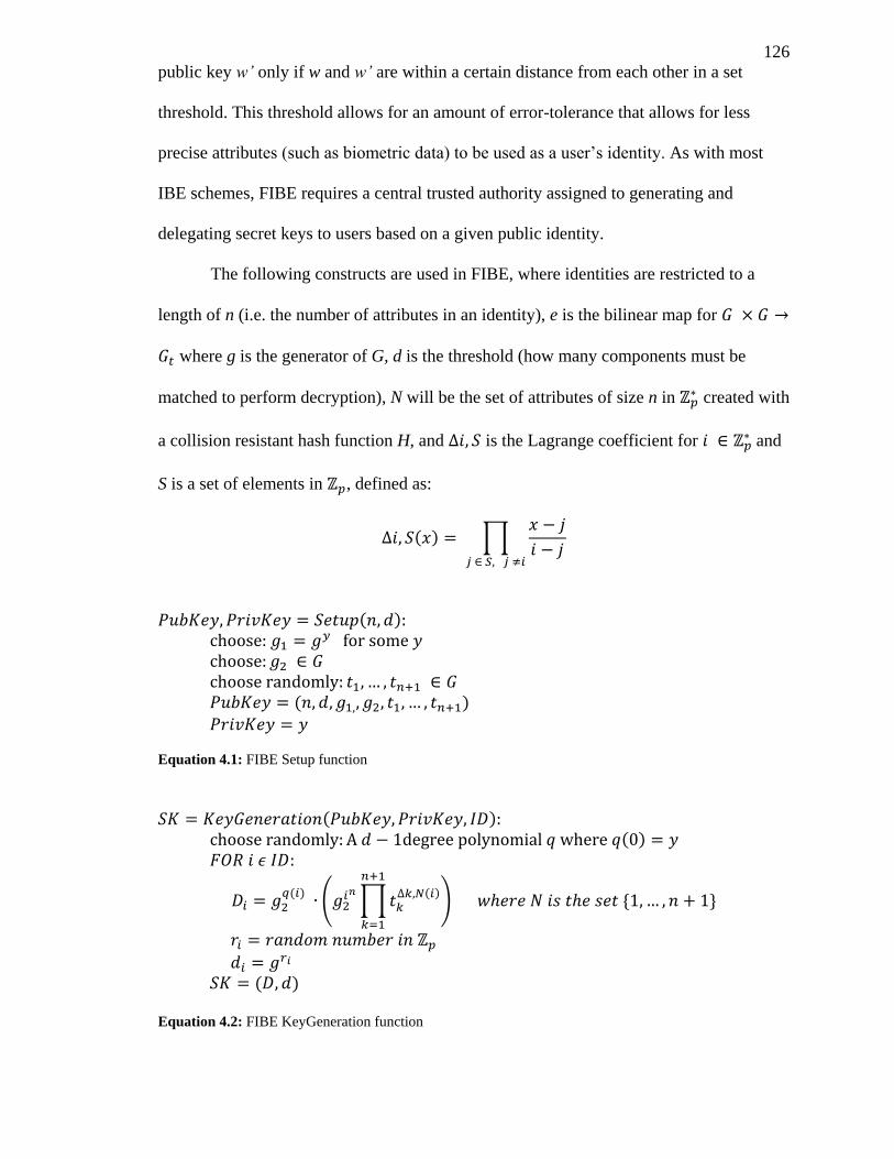
126
public key w’ only if w and w’ are within a certain distance from each other in a set
threshold. This threshold allows for an amount of error-tolerance that allows for less
precise attributes (such as biometric data) to be used as a user’s identity. As with most
IBE schemes, FIBE requires a central trusted authority assigned to generating and
delegating secret keys to users based on a given public identity.
The following constructs are used in FIBE, where identities are restricted to a
length of n (i.e. the number of attributes in an identity), e is the bilinear map for
where g is the generator of G, d is the threshold (how many components must be
matched to perform decryption), N will be the set of attributes of size n in created with
a collision resistant hash function H, and is the Lagrange coefficient for and
S is a set of elements in , defined as:
( ) ∏
( )
( )
Equation 4.1: FIBE Setup function
( ) ( )
( )
( ∏
( )
)
( )
Equation 4.2: FIBE KeyGeneration function
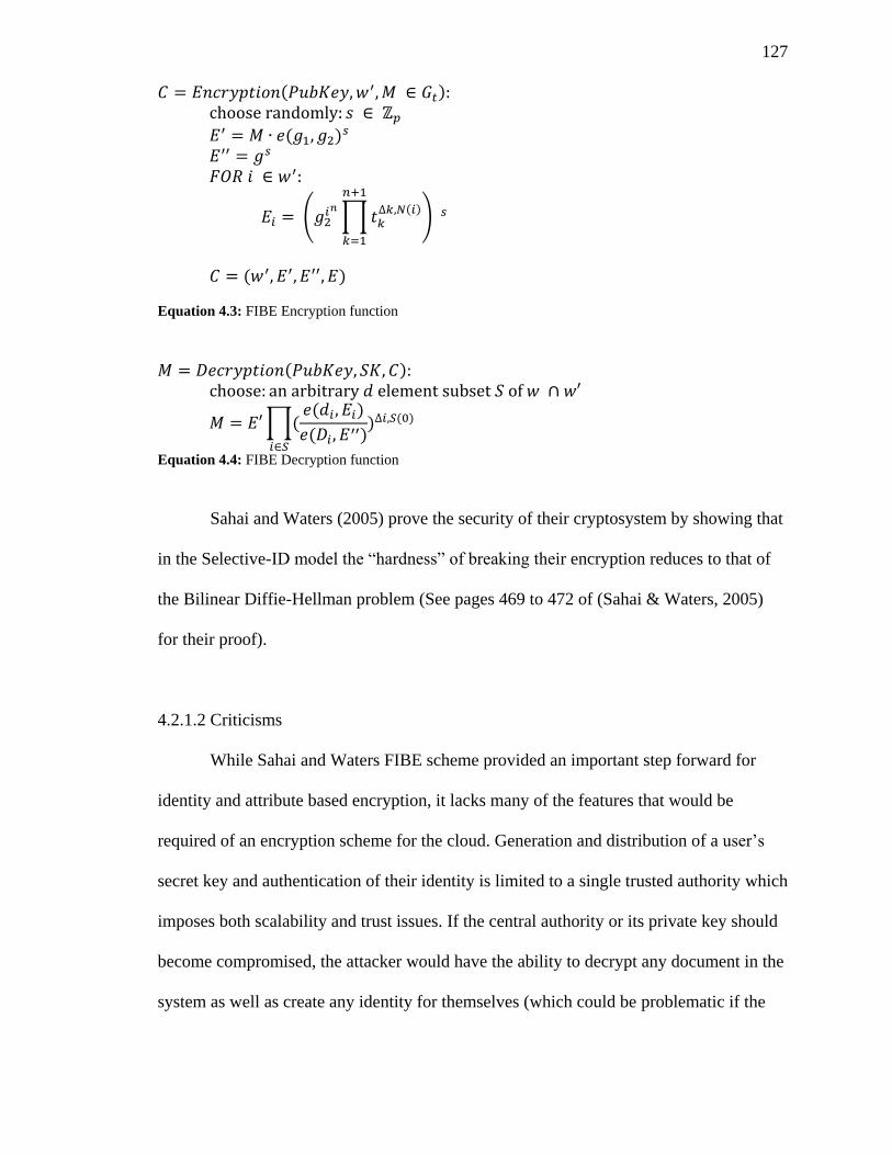
127
( )
( )
( ∏
( )
)
( )
Equation 4.3: FIBE Encryption function
( )
∏( ( )
( )
) ( )
Equation 4.4: FIBE Decryption function
Sahai and Waters (2005) prove the security of their cryptosystem by showing that
in the Selective-ID model the “hardness” of breaking their encryption reduces to that of
the Bilinear Diffie-Hellman problem (See pages 469 to 472 of (Sahai & Waters, 2005)
for their proof).
4.2.1.2 Criticisms
While Sahai and Waters FIBE scheme provided an important step forward for
identity and attribute based encryption, it lacks many of the features that would be
required of an encryption scheme for the cloud. Generation and distribution of a user’s
secret key and authentication of their identity is limited to a single trusted authority which
imposes both scalability and trust issues. If the central authority or its private key should
become compromised, the attacker would have the ability to decrypt any document in the
system as well as create any identity for themselves (which could be problematic if the
128
system is used for creating signatures or proving a user’s identity). A central authority
also significantly limits scalability in systems that require a large number of user keys
generated (for example a system which creates a new user key every session or has keys
set to expire at a regular interval). Copying the master private key to multiple systems
will increase scalability (by distributing user secret key generation requests among them)
at the cost of severely compromising security (if any of the multiple key generation
systems are compromised the whole system is compromised as the same master key is
used).
An additional complication with the security in FIBE, is the lack of a revocation
mechanism. If a user’s secret key is compromised, there is no easy way of revoking their
key or notifying users of the system that the user’s identity has been compromised. This
is made worse by the fact that a user’s identity may not be easily changed (e.g. if
biometric data is used) and would forever be compromised unless every key in the system
is disregarded and a new master private key and set of secret user keys is created for
every user. The use of biometric data as a public key (as suggested in the paper) is also
worrisome. The FIBE scheme may only ensure that a user with a given biometric identity
may possesses it’s corresponding secret key, however, it still discloses that biometric
identity in the form of a public key which may affect the security of other systems that
rely on the secrecy of such data that is unchangeable (as it is physically part of the user).
Another issue with FIBE is the lack of fine grained access control. FIBE offers
only a simple d attributes out of n based policy for encrypting documents. In real life
such a simplistic access policy cannot fully represent organizational security policies or
conditional role based access control. For example, a hospital may wish to encrypt a
health record such that a patient (to whom the record belongs), a doctor who is both an
active employee of the hospital and has a current medical licenses, a lab technician with
129
recent certification and no one in a set of persons the patient has specified, have access.
Unless an extremely large number of attributes is created (at least one for every patient
and possible requirement) this sort of access policy is not possible in FIBE. While
simplistic role based access control is possible with FIBE, where each role or permission
is simply mapped to an attribute and documents are encrypted based roles which should
have access to the file. More modern RBAC systems which have conditional or more
complex mappings of permissions to roles or roles to users (for example a user may only
activate one role at a time, SSD and DSD constraints or other conditions a user must pass
before activating a role) are not possible with FIBE.
Finally FIBE uses a fixed value of d, the threshold in |w ∩ w’| > d (how many
components in the identity must be matched to allow decryption), which limits the access
policies that maybe used. The solution to this issues presented by Sahai and Waters is
limited to creating multiple master private keys and sets of secret keys for each user or
adding a very large amount of “dummy” attributes that would be assigned to every user
in the system (thus vastly increasing the size of every user’s secret key and the time to
decrypt and encrypt a given message).
4.2.2 Attribute-Based Encryption for Fine-Grained Access Control of Encrypted Data
(Goyal, Pandey, Sahai, & Waters, 2006)
4.2.2.1 Summary
Key-Policy Attribute-Based Encryption (KP-ABE) (Goyal, Pandey, Sahai, &
Waters, 2006) is an ABE scheme which embeds access control policies in the user’s key
rather than incorporating them into the ciphertext during encryption. KP-ABE builds
upon the attribute encryption applications of FIBE and replaces the simplistic “d of n
attributes” threshold access policy with a tree access structure consisting of AND and OR
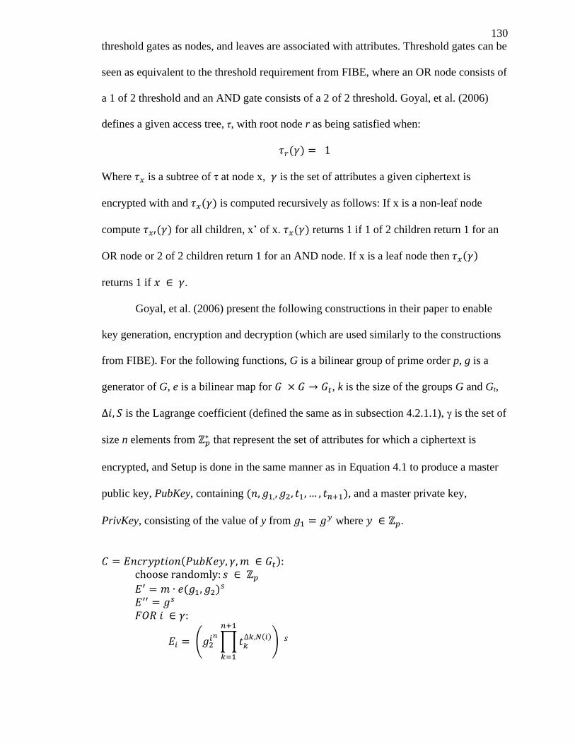
130
threshold gates as nodes, and leaves are associated with attributes. Threshold gates can be
seen as equivalent to the threshold requirement from FIBE, where an OR node consists of
a 1 of 2 threshold and an AND gate consists of a 2 of 2 threshold. Goyal, et al. (2006)
defines a given access tree, τ, with root node r as being satisfied when:
( )
Where is a subtree of τ at node x, is the set of attributes a given ciphertext is
encrypted with and ( ) is computed recursively as follows: If x is a non-leaf node
compute ( ) for all children, x’ of x. ( ) returns 1 if 1 of 2 children return 1 for an
OR node or 2 of 2 children return 1 for an AND node. If x is a leaf node then ( )
returns 1 if .
Goyal, et al. (2006) present the following constructions in their paper to enable
key generation, encryption and decryption (which are used similarly to the constructions
from FIBE). For the following functions, G is a bilinear group of prime order p, g is a
generator of G, e is a bilinear map for , k is the size of the groups G and Gt,
is the Lagrange coefficient (defined the same as in subsection 4.2.1.1), γ is the set of
size n elements from that represent the set of attributes for which a ciphertext is
encrypted, and Setup is done in the same manner as in Equation 4.1 to produce a master
public key, PubKey, containing ( ), and a master private key,
PrivKey, consisting of the value of y from where .
( )
( )
( ∏
( )
)
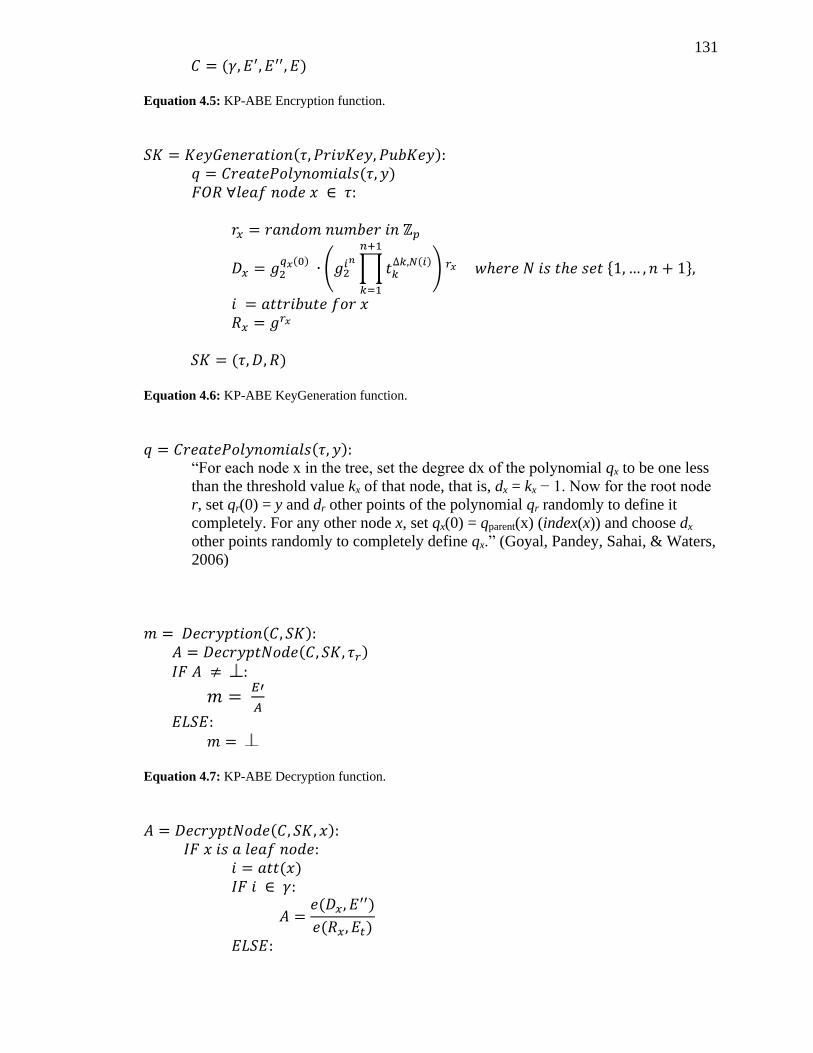
131
( )
Equation 4.5: KP-ABE Encryption function.
( ) ( )
( ) (
∏ ( )
)
( )
Equation 4.6: KP-ABE KeyGeneration function.
( ) “For each node x in the tree, set the degree dx of the polynomial qx to be one less
than the threshold value kx of that node, that is, dx = kx − 1. Now for the root node
r, set qr(0) = y and dr other points of the polynomial qr randomly to define it
completely. For any other node x, set qx(0) = qparent(x) (index(x)) and choose dx
other points randomly to completely define qx.” (Goyal, Pandey, Sahai, & Waters,
2006)
( ) ( )
Equation 4.7: KP-ABE Decryption function.
( )
( )
(
)
( )
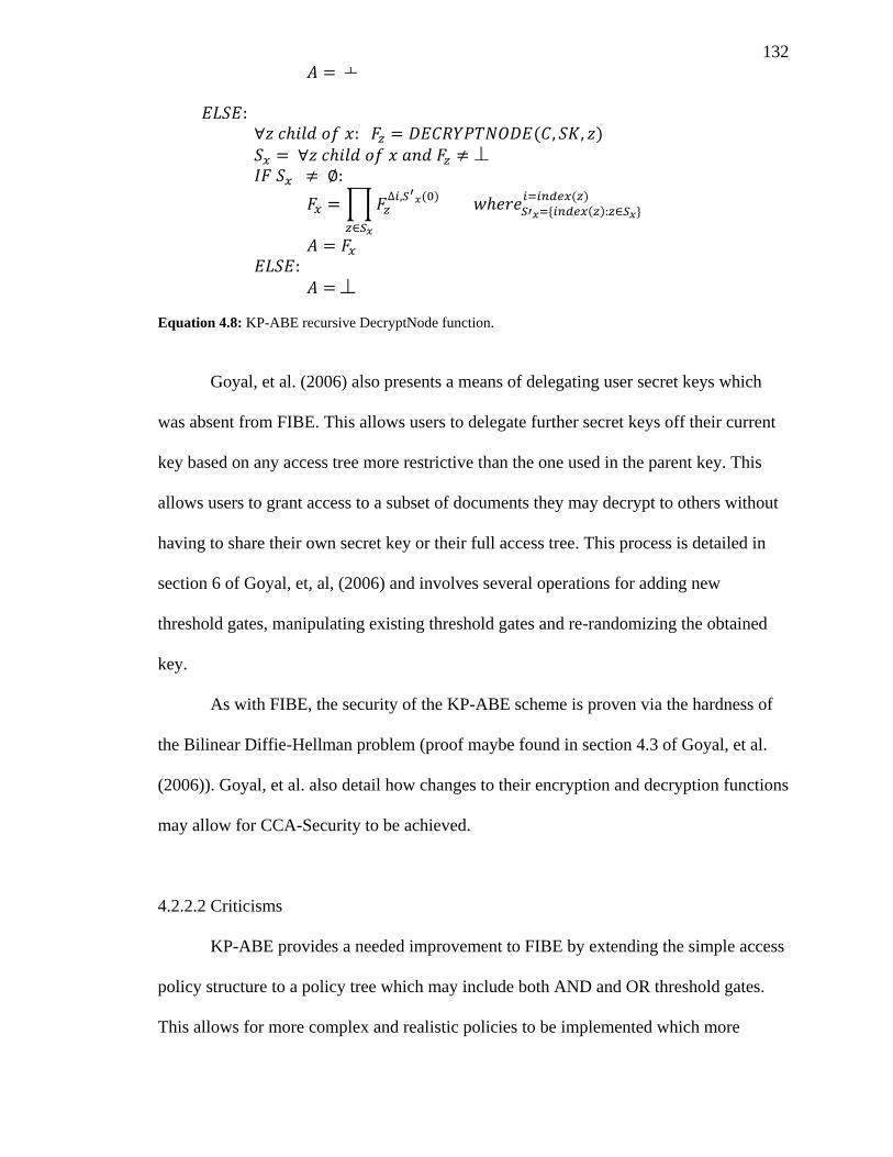
132
( )
∏
( )
( ) ( )
Equation 4.8: KP-ABE recursive DecryptNode function.
Goyal, et al. (2006) also presents a means of delegating user secret keys which
was absent from FIBE. This allows users to delegate further secret keys off their current
key based on any access tree more restrictive than the one used in the parent key. This
allows users to grant access to a subset of documents they may decrypt to others without
having to share their own secret key or their full access tree. This process is detailed in
section 6 of Goyal, et, al, (2006) and involves several operations for adding new
threshold gates, manipulating existing threshold gates and re-randomizing the obtained
key.
As with FIBE, the security of the KP-ABE scheme is proven via the hardness of
the Bilinear Diffie-Hellman problem (proof maybe found in section 4.3 of Goyal, et al.
(2006)). Goyal, et al. also detail how changes to their encryption and decryption functions
may allow for CCA-Security to be achieved.
4.2.2.2 Criticisms
KP-ABE provides a needed improvement to FIBE by extending the simple access
policy structure to a policy tree which may include both AND and OR threshold gates.
This allows for more complex and realistic policies to be implemented which more
133
closely resemble organizational policies in the real world. However, as KP-ABE is
closely based on FIBE it shares many of the criticisms noted of FIBE. A single central
trusted authority is still required for user key creation, which acts as both a scalability and
trust bottle neck. Again there is no easy means of revocation for user keys; in fact the
issue is made worse by enabling a user to further delegate their keys (a compromised key
could make an unlimited number of new keys for the same or more restrictive access
policy).
Having the access policy embedded in the key rather than the ciphertext also has
some potential issues. Encrypting documents with a set of attributes may inadvertently
leak potentially sensitive information about the document. For example, if a hospital
wished to encrypt some sensitive medical document about a patient’s chemotherapy
treatment such that only that patient, doctors belonging to the hospital staff, or a
technician/nurse who gives the chemotherapy treatments, they may encrypt the document
with the following set of attributes {“staff”, “patient:john doe”, “doctor”,
“technician:chemo”}. While such attributes maybe necessary to enforce the policies in
the user keys (for example a chemo technician in the hospital may have the policy
amounting to “technician:chemo AND staff”, a doctor may have “staff AND doctor”, and
the patient John Doe may have “patient:john doe”) it also leaks the sensitive information
that the document details records about John Doe involving chemotherapy (or at least
involving a chemotherapy technician).
Additionally, the key policy based access policy also has potential issues when
designing the access policies for a system. During the encryption of documents, the
encryptor is required to have a good understanding of all policies currently assigned to
users to determine the set of attributes that should be used. Even assuming the encryptor
has a list of all attributes used in all key policies, they are left adding all possible
134
attributes that may be relevant and hoping for the best. In the alterative, a ciphertext
policy based system, the encryptor would set the access policy on each message it
encrypts and is only left trusting that the authority has correctly assigned attributes to
users. It stands to reason that the encryptor would have a better understanding of what
access policy is needed at the time of encryption than the key generator, possibly months,
if not years, in advance.
Finally, while KP-ABE greatly increases the possible complexity of the access
policies used over FIBE, it is still not a complete solution. KP-ABE introduces the use of
AND and OR gates, allowing policies such as “is_teacher OR (is_student AND has_
departmental_approval_to_use_lab)” but it is still incapable of policies that require
variable attributes (attributes that may be assigned a value rather than a user merely
having them) and compressions between them, for example “is_teacher OR (is_student
AND year_level = 4 AND credits > 20)”. Variable attributes and the Boolean
comparisons between them allow for even more complex policies which come even
closer to modeling policies of real world organizations.
4.2.3 Ciphertext-policy attribute-based encryption (Bethencourt, Sahai, & Waters, 2007)
4.2.3.1 Summary
Ciphertext-policy attribute-based encryption (CP-ABE) (Bethencourt, Sahai, &
Waters, 2007) offers a new encryption scheme which continues the work on attribute
based encryption to enable a complex tree based access policy to be embedded in the
ciphertext rather than the key as with KP-ABE. CP-ABE also introduces “variable
attributes” which use a set of traditional attributes to represent a value that can be
evaluated with more complex operations (including >, <, <. > and =). This is
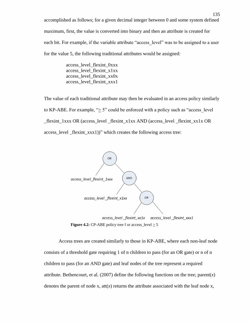
135
accomplished as follows; for a given decimal integer between 0 and some system defined
maximum, first, the value is converted into binary and then an attribute is created for
each bit. For example, if the variable attribute “access_level” was to be assigned to a user
for the value 5, the following traditional attributes would be assigned:
access_level_flexint_0xxx
access_level_flexint_x1xx
access_level_flexint_xx0x
access_level_flexint_xxx1
The value of each traditional attribute may then be evaluated in an access policy similarly
to KP-ABE. For example, “> 5” could be enforced with a policy such as “access_level
_flexint_1xxx OR (access_level _flexint_x1xx AND (access_level _flexint_xx1x OR
access_level _flexint_xxx1))” which creates the following access tree:
Access trees are created similarly to those in KP-ABE, where each non-leaf node
consists of a threshold gate requiring 1 of n children to pass (for an OR gate) or n of n
children to pass (for an AND gate) and leaf nodes of the tree represent a required
attribute. Bethencourt, et al. (2007) define the following functions on the tree; parent(x)
denotes the parent of node x, att(x) returns the attribute associated with the leaf node x,
Figure 4.2: CP-ABE policy tree f or access_level > 5
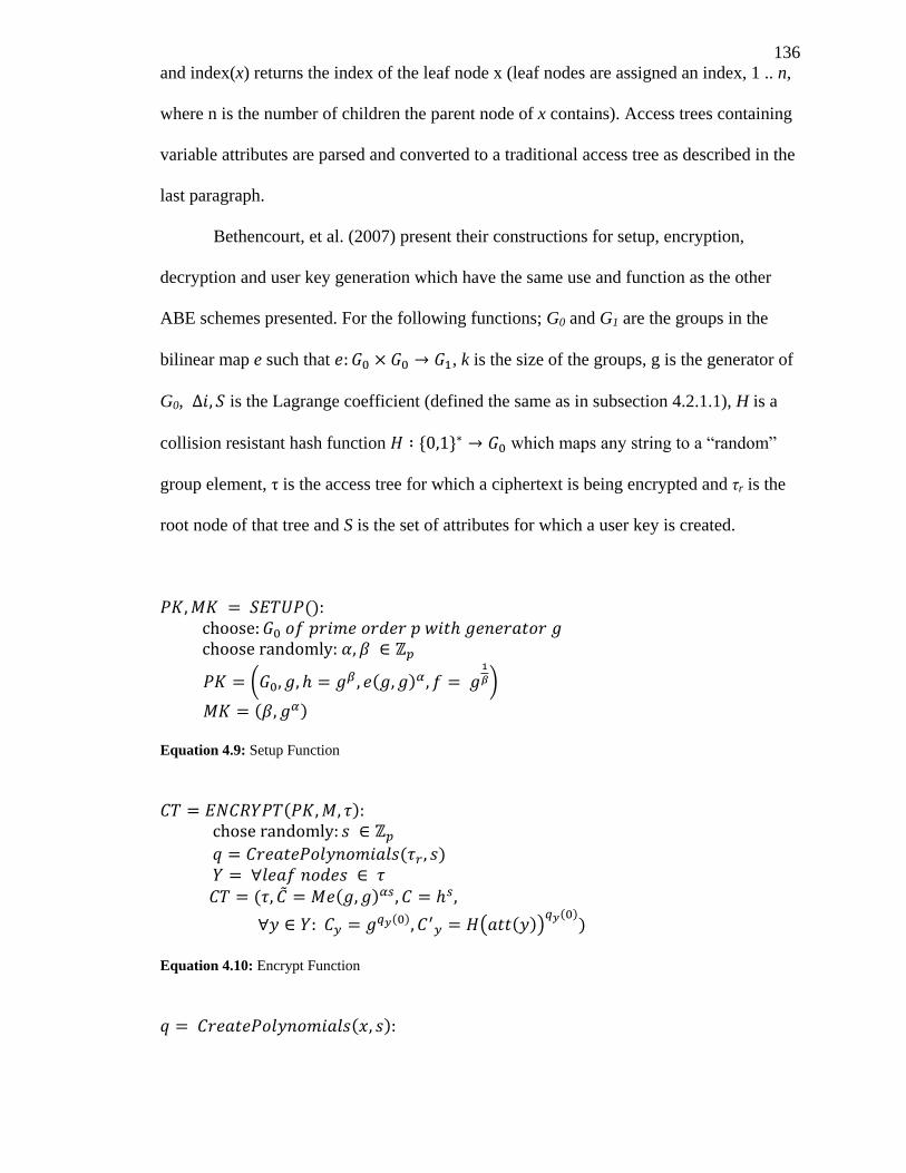
136
and index(x) returns the index of the leaf node x (leaf nodes are assigned an index, 1 .. n,
where n is the number of children the parent node of x contains). Access trees containing
variable attributes are parsed and converted to a traditional access tree as described in the
last paragraph.
Bethencourt, et al. (2007) present their constructions for setup, encryption,
decryption and user key generation which have the same use and function as the other
ABE schemes presented. For the following functions; G0 and G1 are the groups in the
bilinear map e such that , k is the size of the groups, g is the generator of
G0, is the Lagrange coefficient (defined the same as in subsection 4.2.1.1), H is a
collision resistant hash function which maps any string to a “random”
group element, τ is the access tree for which a ciphertext is being encrypted and τr is the
root node of that tree and S is the set of attributes for which a user key is created.
():
( ( )
)
( ) Equation 4.9: Setup Function
( )
( )
( ( )
( ) ( ( ))
( ))
Equation 4.10: Encrypt Function
( )
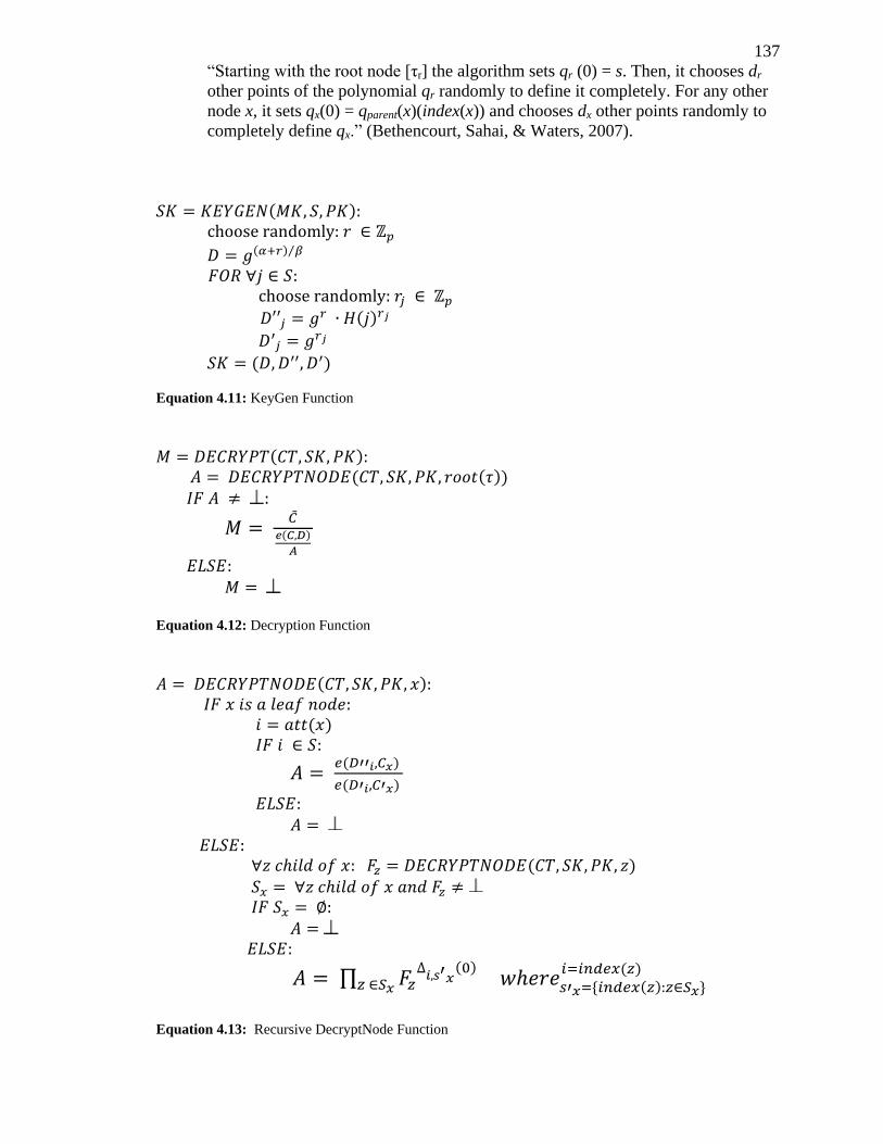
137
“Starting with the root node [τr] the algorithm sets qr (0) = s. Then, it chooses dr
other points of the polynomial qr randomly to define it completely. For any other
node x, it sets qx(0) = qparent(x)(index(x)) and chooses dx other points randomly to
completely define qx.” (Bethencourt, Sahai, & Waters, 2007).
( )
( ) ⁄
( )
( )
Equation 4.11: KeyGen Function
( ) ( ( ))
( )
Equation 4.12: Decryption Function
( ) ( )
( )
( )
( )
∏
( ) ( )
( )
Equation 4.13: Recursive DecryptNode Function
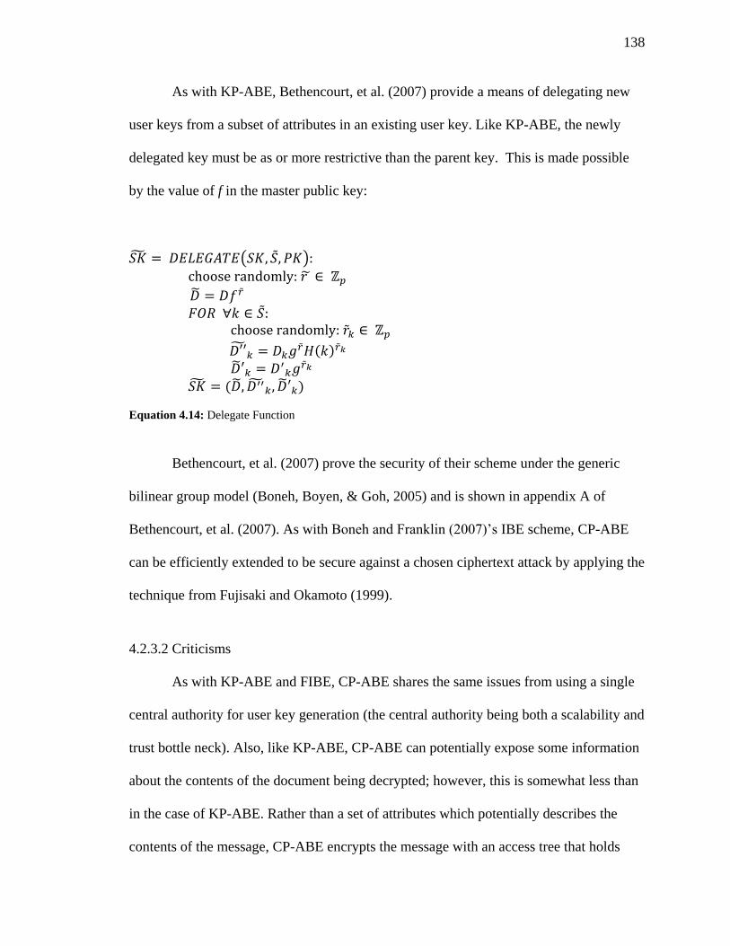
138
As with KP-ABE, Bethencourt, et al. (2007) provide a means of delegating new
user keys from a subset of attributes in an existing user key. Like KP-ABE, the newly
delegated key must be as or more restrictive than the parent key. This is made possible
by the value of f in the master public key:
( )
( )
( )
Equation 4.14: Delegate Function
Bethencourt, et al. (2007) prove the security of their scheme under the generic
bilinear group model (Boneh, Boyen, & Goh, 2005) and is shown in appendix A of
Bethencourt, et al. (2007). As with Boneh and Franklin (2007)’s IBE scheme, CP-ABE
can be efficiently extended to be secure against a chosen ciphertext attack by applying the
technique from Fujisaki and Okamoto (1999).
4.2.3.2 Criticisms
As with KP-ABE and FIBE, CP-ABE shares the same issues from using a single
central authority for user key generation (the central authority being both a scalability and
trust bottle neck). Also, like KP-ABE, CP-ABE can potentially expose some information
about the contents of the document being decrypted; however, this is somewhat less than
in the case of KP-ABE. Rather than a set of attributes which potentially describes the
contents of the message, CP-ABE encrypts the message with an access tree that holds
139
potentially less sensitive information in some cases. For example, the case used in section
4.2.2.2; a hospital wishing to encrypt some sensitive medical document about a patient’s
chemotherapy treatment such that only doctors belonging to the hospital staff or a
technician/nurse who gives the chemotherapy treatments, may encrypt the document with
the following access policy:
“ (staff AND (doctor OR (technician AND department > 120 AND department <
125))) OR (patient AND user_id = 304831)”
In this case only the patient’s user_id and the fact that technicians from departments 120
to 124 may access the document is disclosed. In some cases this may still be too much
information and it may be possible to map the user_id back to a full name.
Another improvement on KP-ABE and FIBE is the possibility of User Key
revocation which is made possible in CP-ABE through the use of variable attributes. A
user key may be created with an expiry date (e.g. “expire = 1278176400” the unix time
stamp for July 3rd
, 2010 at noon) and files may be encrypted with an access tree structure
containing a limit on the expiry date (e.g. “expire > 1310187600”, time stamp for July 9th
2011 at midnight). If a CP-ABE based system is made to set this limit to the current date
and time of the file’s encryption and the key issuer creates user keys with an expiry
attribute at a set time in the future, it would limit users of the system to only decrypting
documents created before the expiry date. After the expiry date, a user would be forced to
obtain a new key or be unable to access any future documents in the system.
While CP-ABE adds new operations to the access tree, including greater than, less
than, greater than or equals, less than or equals, and equals, it does not provide a not
equals operation. Such an operation may seem unnecessary, as an attribute in a user’s key
may simply be omitted to limit their access to a file. However, there are cases where such
functionality is required. For example, many privacy laws (as detailed in section 1.2)
140
require that a person be able to limit access to who has access to their sensitive
information (e.g. a patient may wish to prevent a particular doctor from accessing their
health record which he/she would otherwise have access to). A not equals operation
would enable this and allow for the creation of access policies such as “is_staff AND
is_doctor AND user_id ≠ 81037”.
Finally, the security of CP-ABE has only been proven with the generic group
model. Meaning that if any security vulnerability exists in the scheme, it would have to
exploit the cryptographic hash functions used or a mathematical property of elliptic curve
groups used in the scheme (see appendix A of Bethencourt, et al. (2007) for more
details). Recent work in ciphertext policy based ABE has resulted in CP-ABE schemes
proven secure under more common assumptions (Waters, 2011) without significantly
impacting the efficiency of the system.
4.2.4 Self-Protecting Electronic Medical Records Using Attribute-Based Encryption
(Akinyele, Lehmann, Green, Pagano, Peterson, & Rubin, 2010)
4.2.4.1 Summary
J. Akinyele et al. (2010) present one of the first attempts at using CP-ABE for
protecting electronic health records in their 2010 technical report “Self- Protecting
Electronic Medical Records Using Attribute-Based Encryption”. Their approach uses the
somewhat naive method of directly applying an existing KP-ABE or CP-ABE scheme to
XML formatted health records (specifically the CCR and CCD format). The novel
contribution comes in the form of automated policy generation and visualization of EHRs
for a KP-ABE system and extending the CCR and CCD formats to support ABE based
encryption. J. Akinyele et al.’s (2010) policy engine is initialized with configuration
options determining the ABE scheme to be used and a rule set dictating a high level view
141
of the encryption policies to be applied to records based on the contents. As records are
passed to the engine, ABE policies are chosen based on the contents of each node in the
XML record and encrypted with the specified scheme if the records’ contents are deemed
sensitive.
User key generation and assignment is done through an entity entitled the “ABE
master controller”. The ABE master controller is essentially an offline version of the user
key generator required by most ABE schemes, in which an authorized user manually
generates and distributes keys to hospital patients and staff. In cases where the rule set
used by the policy engine requires both KP-ABE and CP-ABE encryption policies,
multiple keys may be distributed to each user by the ABE master controller.
J. Akinyele et al. (2010) also detail how their system may be used with a mobile
platform for decrypting and using ABE encrypted CCR/CCD health records. A python
based implementation of their policy engine and an implementation of their iPhone
“iHealthEMR” client is presented. Finally, it is suggested that this system could be used
with cloud based services such as Google Health for safe online record storage.
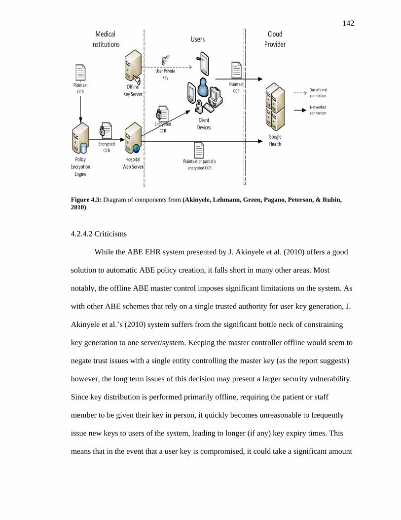
142
Figure 4.3: Diagram of components from (Akinyele, Lehmann, Green, Pagano, Peterson, & Rubin,
2010).
4.2.4.2 Criticisms
While the ABE EHR system presented by J. Akinyele et al. (2010) offers a good
solution to automatic ABE policy creation, it falls short in many other areas. Most
notably, the offline ABE master control imposes significant limitations on the system. As
with other ABE schemes that rely on a single trusted authority for user key generation, J.
Akinyele et al.’s (2010) system suffers from the significant bottle neck of constraining
key generation to one server/system. Keeping the master controller offline would seem to
negate trust issues with a single entity controlling the master key (as the report suggests)
however, the long term issues of this decision may present a larger security vulnerability.
Since key distribution is performed primarily offline, requiring the patient or staff
member to be given their key in person, it quickly becomes unreasonable to frequently
issue new keys to users of the system, leading to longer (if any) key expiry times. This
means that in the event that a user key is compromised, it could take a significant amount
143
of time or effort to revoke it. As it is expected that user keys will be stored on mobile
devices in this system that can be easily lost or stolen, it seems likely that it would be
more probable that a user key could become compromised than a secured ABE master
controller system.
Additionally, an offline ABE master controller also constrains the usefulness of
the system. It seems unlikely that all patients would be able to meet with the person in
charge of the ABE master controller in person or have the necessary knowledge to utilize
the raw key. In an online system, a patient could download a client and supply personal
details to be authorized for the creation and delegation of a user key over a secure
channel (such as SSL). Such systems already exist and are used frequently which store
and process highly confidential information over the internet such as online banking and
tax filing software, so it would seem reasonable that with the proper security measures
any risk an online system possesses could be minimized. Furthermore, J. Akinyele et al.’s
(2010) system lacks any means for outside health providers to share encrypted health
records. In many cases doctors’ offices, hospitals, specialists, researchers and outside labs
need to communicate sensitive health information. The presented system has no means to
enable this without in-person key delegation and is largely localized to a single
institution.
While an effort is made to secure the ABE master controller from compromise by
limiting it to an offline system, little thought is given to the online policy engine system.
In many ways the policy engine is just as vulnerable to tampering as all health records are
processed, encrypted and sent from this system. An attacker who obtained access to the
policy engine could easily change the rules set being used, to create a “back door”
attribute requirement (e.g. “OR user_id = 12345” where 12345 is the attackers user_id) in
all future ciphertexts. Additionally, an attacker with access to the policy engine system
144
could simply eavesdrop on all records sent to the policy engine as they are sent in their
plain text CCR/CCD format. In effect, the potential vulnerabilities of a compromised
ABE master controller are simply shifted to the policy engine system, further
undermining the advantage of placing the controller offline.
Finally, the suggested use of GoogleHealth and other cloud services falls short as
it would amount to being solely an online storage system with no processing or viewing
capabilities when the records are encrypted and lose all privacy protections when the
records are sent unencrypted. Even when the records are stored fully encrypted on the
cloud there is still the potential of unintentional information leakage depending on the
attributes or policy used to encrypt the record. As shown with KP-ABE and CP-ABE (in
sections 4.2.3.2 and 4.2.2.2), attributes and access trees embedded in the cihpertext may
reveal some information about the contents of the file (e.g. if the name of the patient was
used as an attribute to encrypt the file in KP-ABE and attribute names were public).
4.3 Distributed Multi-Authority Ciphertext-Policy Shared
Attribute-Based Encryption (DMACPSABE)
4.3.1 Introduction
We present a distributed multi-authority ciphertext-policy shared attribute-based
encryption (DMACPSABE) scheme built on the work of Bethencourt, et al.’s (2007)
Ciphertext-policy Attribute-Based Encryption (CP-ABE). Our scheme adds support for
multiple distributed attribute authorities, capable of generating user keys, which share
some given subset of attributes for which they are authorized. We introduce a new
hierarchal authorization data structure (section 4.3.2.1) for attribute authorities which
dictate the private and shared set of constant and variable attributes a given authority will
have permission to delegate to users. A new not equals operation (section 4.3.2.6) for CP-
145
ABE is detailed and its implications described, performance improvements (section
4.4.2) are discussed and tested, and a means for creating policies based on a user’s origin
(to which attribute authority they belong) is detailed (section 4.3.2.7). Additionally, our
scheme provides a natural layer of anonymization for the attributes used in the access
trees embedded in the ciphertext (an issue with traditional CP-ABE and KP-ABE)
(section 4.3.2.8).
We present an implementation of our scheme (section 4.4.1) and evaluate its
performance against Bethencourt, et al.’s (2007) CP-ABE implementation. A security
evaluation and discussion is also presented in section 4.4.4.
4.3.2 Constructions
Our DMACPSABE encryption scheme extends the SETUP (Equation 4.9),
ENCRYPT (Equation 4.10), DECRYPT (Equation 4.12), DELEGATE (Equation 4.14)
and KEYGEN (Equation 4.11) functions from J. Bethencourt, et al.’s (2007) Ciphertext-
policy attribute-based encryption model to enable multi-authority user key assignment
and delegation. Each user authority is delegated a set of attributes for which it has
authority over (power to further delegate the attributes to users) from an offline master
authority. The master authority is only required during the initial creation of a new user
authority or attribute.
The following sub-sections outline the extensions to each function. As with the J.
Bethencourt, et al.’s (2007) constructions presented in 4.2.3, is a bilinear group of
prime order p and size k for which g is the generator of and denotes
the bilinear map.
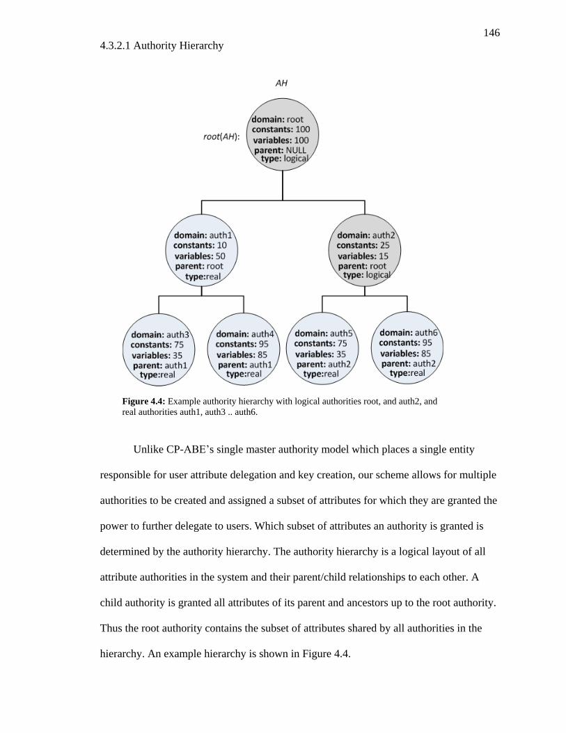
146
4.3.2.1 Authority Hierarchy
Unlike CP-ABE’s single master authority model which places a single entity
responsible for user attribute delegation and key creation, our scheme allows for multiple
authorities to be created and assigned a subset of attributes for which they are granted the
power to further delegate to users. Which subset of attributes an authority is granted is
determined by the authority hierarchy. The authority hierarchy is a logical layout of all
attribute authorities in the system and their parent/child relationships to each other. A
child authority is granted all attributes of its parent and ancestors up to the root authority.
Thus the root authority contains the subset of attributes shared by all authorities in the
hierarchy. An example hierarchy is shown in Figure 4.4.
Figure 4.4: Example authority hierarchy with logical authorities root, and auth2, and
real authorities auth1, auth3 .. auth6.
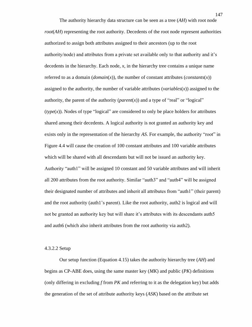
147
The authority hierarchy data structure can be seen as a tree (AH) with root node
root(AH) representing the root authority. Decedents of the root node represent authorities
authorized to assign both attributes assigned to their ancestors (up to the root
authority/node) and attributes from a private set available only to that authority and it’s
decedents in the hierarchy. Each node, x, in the hierarchy tree contains a unique name
referred to as a domain (domain(x)), the number of constant attributes (constants(x))
assigned to the authority, the number of variable attributes (variables(x)) assigned to the
authority, the parent of the authority (parent(x)) and a type of “real” or “logical”
(type(x)). Nodes of type “logical” are considered to only be place holders for attributes
shared among their decedents. A logical authority is not granted an authority key and
exists only in the representation of the hierarchy AS. For example, the authority “root” in
Figure 4.4 will cause the creation of 100 constant attributes and 100 variable attributes
which will be shared with all descendants but will not be issued an authority key.
Authority “auth1” will be assigned 10 constant and 50 variable attributes and will inherit
all 200 attributes from the root authority. Similar “auth3” and “auth4” will be assigned
their designated number of attributes and inherit all attributes from “auth1” (their parent)
and the root authority (auth1’s parent). Like the root authority, auth2 is logical and will
not be granted an authority key but will share it’s attributes with its descendants auth5
and auth6 (which also inherit attributes from the root authority via auth2).
4.3.2.2 Setup
Our setup function (Equation 4.15) takes the authority hierarchy tree (AH) and
begins as CP-ABE does, using the same master key (MK) and public (PK) definitions
(only differing in excluding f from PK and referring to it as the delegation key) but adds
the generation of the set of attribute authority keys (ASK) based on the attribute set
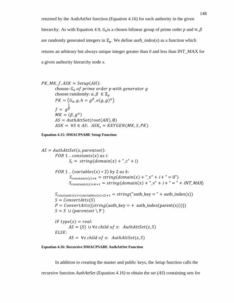
148
returned by the AuthAttSet function (Equation 4.16) for each authority in the given
hierarchy. As with Equation 4.9, is a chosen bilinear group of prime order p and
are randomly generated integers in . We define auth_index(x) as a function which
returns an arbitrary but always unique integer greater than 0 and less than INT_MAX for
a given authority hierarchy node x.
( )
( ( ) )
( )
( ( ) )
( )
Equation 4.15: DMACPSABE Setup Function
( ) ( )
( ( ) )
( ( ) ) ( ) ( ( ) )
( ) ( ( ) )
( ) ( ( ) ) ( ( ))
( )
( ( ( ( ))) )
( )
( ) ( )
( )
Equation 4.16: Recursive DMACPSABE AuthAttSet Function
In addition to creating the master and public keys, the Setup function calls the
recursive function AuthAttSet (Equation 4.16) to obtain the set (AS) containing sets for
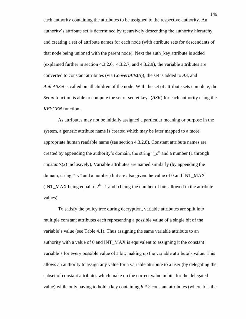
149
each authority containing the attributes to be assigned to the respective authority. An
authority’s attribute set is determined by recursively descending the authority hierarchy
and creating a set of attribute names for each node (with attribute sets for descendants of
that node being unioned with the parent node). Next the auth_key attribute is added
(explained further in section 4.3.2.6, 4.3.2.7, and 4.3.2.9), the variable attributes are
converted to constant attributes (via ConvertAtts(S)), the set is added to AS, and
AuthAttSet is called on all children of the node. With the set of attribute sets complete, the
Setup function is able to compute the set of secret keys (ASK) for each authority using the
KEYGEN function.
As attributes may not be initially assigned a particular meaning or purpose in the
system, a generic attribute name is created which may be later mapped to a more
appropriate human readable name (see section 4.3.2.8). Constant attribute names are
created by appending the authority’s domain, the string “_c” and a number (1 through
constants(x) inclusively). Variable attributes are named similarly (by appending the
domain, string “_v” and a number) but are also given the value of 0 and INT_MAX
(INT_MAX being equal to 2b - 1 and b being the number of bits allowed in the attribute
values).
To satisfy the policy tree during decryption, variable attributes are split into
multiple constant attributes each representing a possible value of a single bit of the
variable’s value (see Table 4.1). Thus assigning the same variable attribute to an
authority with a value of 0 and INT_MAX is equivalent to assigning it the constant
variable’s for every possible value of a bit, making up the variable attribute’s value. This
allows an authority to assign any value for a variable attribute to a user (by delegating the
subset of constant attributes which make up the correct value in bits for the delegated
value) while only having to hold a key containing b * 2 constant attributes (where b is the
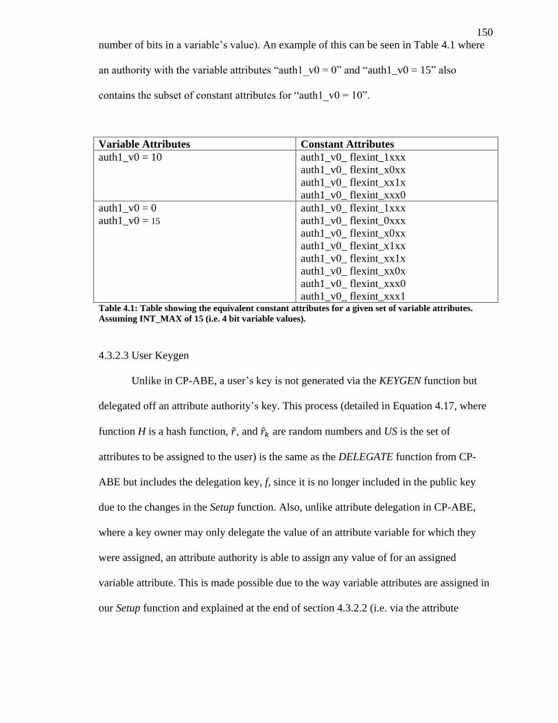
150
number of bits in a variable’s value). An example of this can be seen in Table 4.1 where
an authority with the variable attributes “auth1_v0 = 0” and “auth1_v0 = 15” also
contains the subset of constant attributes for “auth1_v0 = 10”.
Variable Attributes Constant Attributes
auth1_v0 = 10 auth1_v0_ flexint_1xxx
auth1_v0_ flexint_x0xx
auth1_v0_ flexint_xx1x
auth1_v0_ flexint_xxx0
auth1_v0 = 0
auth1_v0 = 15
auth1_v0_ flexint_1xxx
auth1_v0_ flexint_0xxx
auth1_v0_ flexint_x0xx
auth1_v0_ flexint_x1xx
auth1_v0_ flexint_xx1x
auth1_v0_ flexint_xx0x
auth1_v0_ flexint_xxx0
auth1_v0_ flexint_xxx1 Table 4.1: Table showing the equivalent constant attributes for a given set of variable attributes.
Assuming INT_MAX of 15 (i.e. 4 bit variable values).
4.3.2.3 User Keygen
Unlike in CP-ABE, a user’s key is not generated via the KEYGEN function but
delegated off an attribute authority’s key. This process (detailed in Equation 4.17, where
function H is a hash function, , and are random numbers and US is the set of
attributes to be assigned to the user) is the same as the DELEGATE function from CP-
ABE but includes the delegation key, f, since it is no longer included in the public key
due to the changes in the Setup function. Also, unlike attribute delegation in CP-ABE,
where a key owner may only delegate the value of an attribute variable for which they
were assigned, an attribute authority is able to assign any value of for an assigned
variable attribute. This is made possible due to the way variable attributes are assigned in
our Setup function and explained at the end of section 4.3.2.2 (i.e. via the attribute
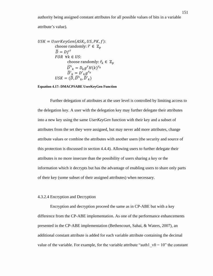
151
authority being assigned constant attributes for all possible values of bits in a variable
attribute’s value).
( )
( )
( )
Equation 4.17: DMACPSABE UserKeyGen Function
Further delegation of attributes at the user level is controlled by limiting access to
the delegation key. A user with the delegation key may further delegate their attributes
into a new key using the same UserKeyGen function with their key and a subset of
attributes from the set they were assigned, but may never add more attributes, change
attribute values or combine the attributes with another users (the security and source of
this protection is discussed in section 4.4.4). Allowing users to further delegate their
attributes is no more insecure than the possibility of users sharing a key or the
information which it decrypts but has the advantage of enabling users to share only parts
of their key (some subset of their assigned attributes) when necessary.
4.3.2.4 Encryption and Decryption
Encryption and decryption proceed the same as in CP-ABE but with a key
difference from the CP-ABE implementation. As one of the performance enhancements
presented in the CP-ABE implementation (Bethencourt, Sahai, & Waters, 2007), an
additional constant attribute is added for each variable attribute containing the decimal
value of the variable. For example, for the variable attribute “auth1_v0 = 10” the constant
152
attribute “auth1_v0_10” would be added. This allows for a performance increase when
the policy tree contains an equals requirement on a variable attribute (e.g. requiring that
auth1_v0 being equal to 10). As this would require each authority being assigned a
constant attribute for each possible value from 0 to INT_MAX (adding significantly to
the time to generate and the size of an authority key) we have omitted this enhancement
and a policy tree is created which requires all attributes that make up the value in binary
to be present (e.g. requiring that a key contains attributes for auth_flexint_1xxx,
auth_flexint_x0xx, flexint_xx1x and flexint_xxx0 rather than just the attribute
auth1_v0_10 being present).
4.3.2.5 Adding/Removing Authorities and Attribute Sets
New attribute authorities may be added to the hierarchy simply by using the
master authority to create the new attribute authority key containing the appropriate set of
constant and variable attributes. It is expected that this operation would be performed
offline manually and the new key would be installed on the new attribute authority
through a secure channel. Similarly, adding attributes or making additive changes to the
authority hierarchy may be performed by generating new attribute authority keys for the
affected authorities. As this is a costly operation (and time consuming if done manually
and offline) it is recommended that a large set of attributes be initially assigned to each
authority to avoid the need to frequently create new attributes. If the changes to an
authority’s key are purely additive (only adding new attributes and not remove any
existing attributes in the key) all current user keys and encrypted documents are still fully
functional and backwards compatible with the new authority key.
In an ideal environment, removing attributes from an authority would be done in a
similar manner (by issuing a new key) and removing an authority would simply involve
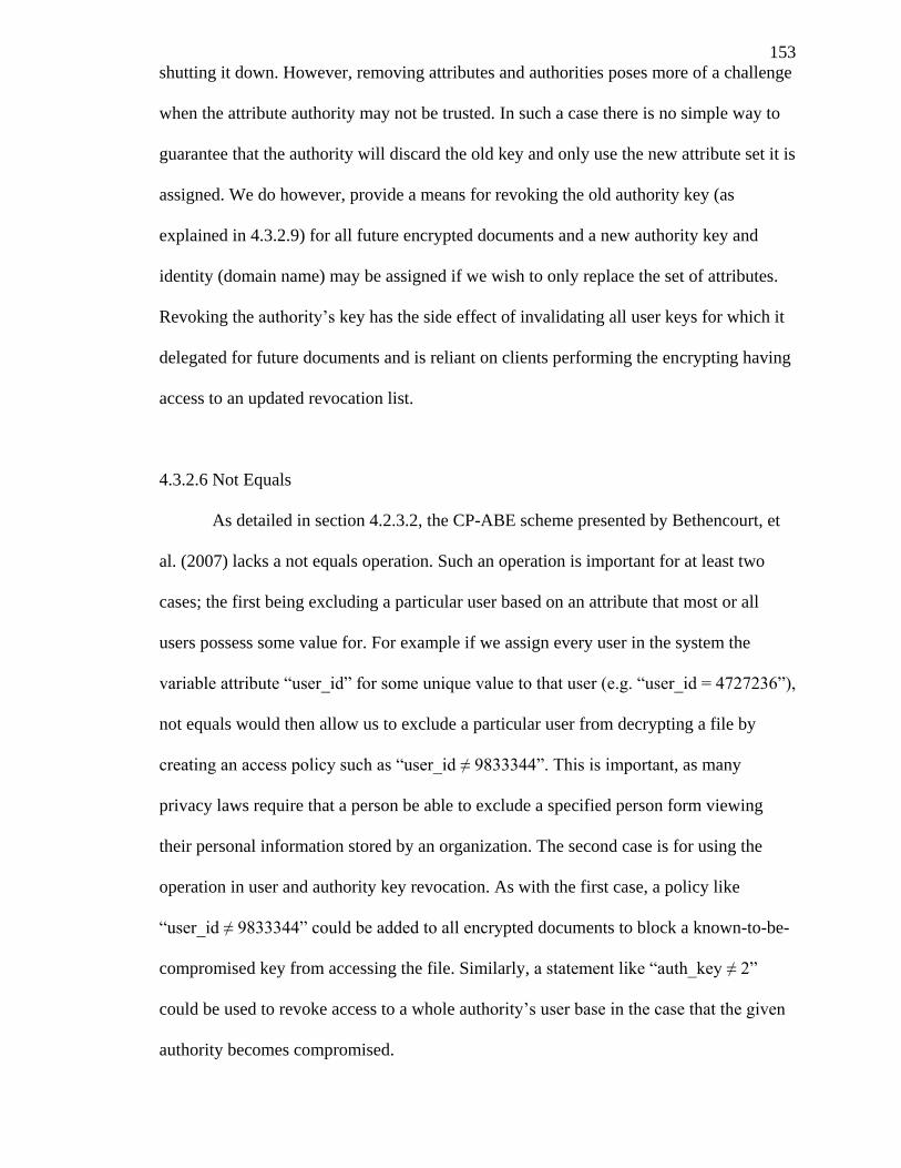
153
shutting it down. However, removing attributes and authorities poses more of a challenge
when the attribute authority may not be trusted. In such a case there is no simple way to
guarantee that the authority will discard the old key and only use the new attribute set it is
assigned. We do however, provide a means for revoking the old authority key (as
explained in 4.3.2.9) for all future encrypted documents and a new authority key and
identity (domain name) may be assigned if we wish to only replace the set of attributes.
Revoking the authority’s key has the side effect of invalidating all user keys for which it
delegated for future documents and is reliant on clients performing the encrypting having
access to an updated revocation list.
4.3.2.6 Not Equals
As detailed in section 4.2.3.2, the CP-ABE scheme presented by Bethencourt, et
al. (2007) lacks a not equals operation. Such an operation is important for at least two
cases; the first being excluding a particular user based on an attribute that most or all
users possess some value for. For example if we assign every user in the system the
variable attribute “user_id” for some unique value to that user (e.g. “user_id = 4727236”),
not equals would then allow us to exclude a particular user from decrypting a file by
creating an access policy such as “user_id ≠ 9833344”. This is important, as many
privacy laws require that a person be able to exclude a specified person form viewing
their personal information stored by an organization. The second case is for using the
operation in user and authority key revocation. As with the first case, a policy like
“user_id ≠ 9833344” could be added to all encrypted documents to block a known-to-be-
compromised key from accessing the file. Similarly, a statement like “auth_key ≠ 2”
could be used to revoke access to a whole authority’s user base in the case that the given
authority becomes compromised.
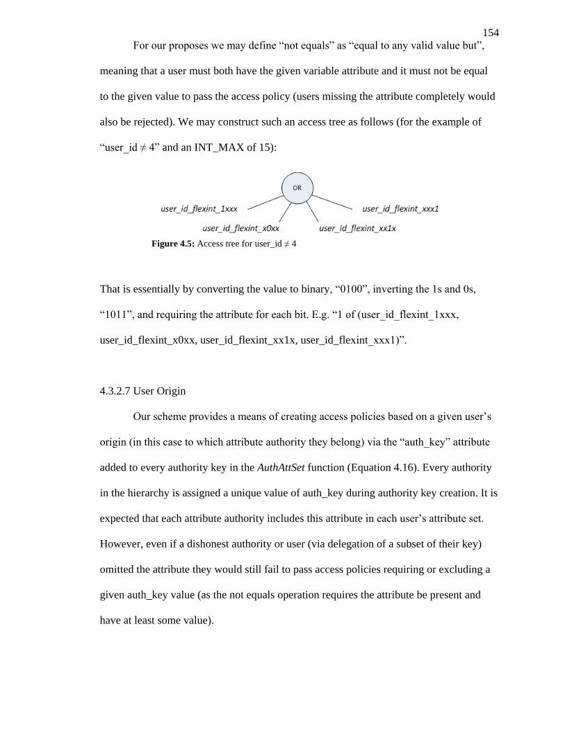
154
For our proposes we may define “not equals” as “equal to any valid value but”,
meaning that a user must both have the given variable attribute and it must not be equal
to the given value to pass the access policy (users missing the attribute completely would
also be rejected). We may construct such an access tree as follows (for the example of
“user_id ≠ 4” and an INT_MAX of 15):
That is essentially by converting the value to binary, “0100”, inverting the 1s and 0s,
“1011”, and requiring the attribute for each bit. E.g. “1 of (user_id_flexint_1xxx,
user_id_flexint_x0xx, user_id_flexint_xx1x, user_id_flexint_xxx1)”.
4.3.2.7 User Origin
Our scheme provides a means of creating access policies based on a given user’s
origin (in this case to which attribute authority they belong) via the “auth_key” attribute
added to every authority key in the AuthAttSet function (Equation 4.16). Every authority
in the hierarchy is assigned a unique value of auth_key during authority key creation. It is
expected that each attribute authority includes this attribute in each user’s attribute set.
However, even if a dishonest authority or user (via delegation of a subset of their key)
omitted the attribute they would still fail to pass access policies requiring or excluding a
given auth_key value (as the not equals operation requires the attribute be present and
have at least some value).
Figure 4.5: Access tree for user_id ≠ 4

155
As attribute authorities likely represent different institutions or departments in the
system, this feature is useful for limiting access to or from a given institution/department
when all other required attributes are shared and no existing attribute performs a similar
role. Additionally, the “auth_key” attribute is used as part of our revocation system for
revoking compromised authority keys (see section 4.3.2.9).
4.3.2.8 Human Readable Attributes
Unlike traditional CP-ABE and KP-ABE schemes which use a hash function to
map descriptive attribute names to attributes, our scheme delegates sets of attributes
before their purpose is known. The result is somewhat obscured attribute
names/identifiers being assigned to users and used in access trees such as “auth1_v1” or
“root_c5”. This actually may be seen as a security feature as it adds a level of anonymity
to attributes and helps prevent the information leakage possible in CP-ABE and KP-ABE.
However, this also presents a potential problem for the encryptors of documents as they
lack the details to determine which attributes to use in their policy.
The following are several potential solutions to this issue which provide, varying
levels of attribute anonymity:
Public Mapping of Attribute Names:
In this case an authority keeps an updated map of attribute names to identifiers
and publicly publishes it. Users of the system would download a copy of the map
periodically (possibly with each key request) and use it for creating access trees when
encrypting documents. This case would provide no attribute anonymity but would easily
allow for creating encrypted messages.
156
Private Mapping of Attribute Names:
In this case an authority keeps an updated map of attribute names to identifiers but
would only provide it to users who are granted the right to create new documents in the
system. Users only re-encrypting documents to make modifications would only need to
use the same access tree as for which the document was encrypted (which is embedded in
the ciphertext and no knowledge of the attributes is needed to use it). This case would
provide attribute anonymity so long as the subset of users who may add documents can
be trusted.
Automatic Policy Generation
In this case, a policy engine such as that presented by Akinyele, et al. (2010) is
used to automate policy creation during document encryption. Such an engine would be
initialized with a rule set containing the high level institutional policies and raw
anonymized attribute identifiers and create access tree policies based on the contents of
the record being encrypted. This case would help ensure the anonymity of attributes as
well as greatly simplify access tree creation, so long as a proper and reliable rule set
could be created.
Each attribute authority in the system and the organization/ institution/department
it represents may independently choose to implement a different method which best
matches their requirements as no one method of attribute name mapping is required to be
imposed on all authorities.
157
4.3.2.9 Revocation and Expiration
User Key Revocation and Expiration
As with the CP-ABE scheme presented by Bethencourt, et al. (2007), user keys
may be set to expire by including a variable attribute, an expiry date and ensuring that all
encrypted documents contain a policy requiring that attribute to be greater than the
current date. This would effectively limit expired user keys to decrypting documents
encrypted before the key expired (which may already have been decrypted/compromised
by the user). Revoking the user key then becomes simply a case of not renewing the key.
Additionally in cases where users have no need to view documents past a set date, a
lower limit may be placed on the expiry attribute to limit access to old documents.
As our scheme adds a not equals operation we are also given the option of
revoking access to a user by excluding an attribute value unique to that user. For
example, if all users are given a unique value for the variable attribute “user_id” one may
simply exclude a given user by adding a policy such as “user_id ≠ 123456” to deny a user
with the id 123456 the ability to decrypt the document. Even if the user removed the
“user_id” attribute from their key, they would still fail to pass the access policy due to the
way not equals is defined (see section 4.3.2.6).
Attribute Authority Revocation and Expiration
The addition of the “auth_key” attribute in AuthAttSet function (Equation 4.16)
allows us to deny access to users whose key was generated by a set authority (i.e. their
origin, see section 4.3.2.7) as we could an individual user via a “user_id” attribute. If an
attribute authority were to become compromised, a notice could be posted in a public
revocation list and future documents could be encrypted with the requirement that
“auth_key ≠ 5” for example, if the authority with an auth_index of 5was compromised.
158
This would effectively prevent any user from that authority from decrypting future
documents.
As with user keys, attribute authority keys could also be created with a set expiry
attribute which it would in turn delegate on to its users. However, unlike the user key
expiry date, which maybe set to only days or hours in the future an authority key would
have to be set to expire significantly longer in the future (possibly months or a year) as
the process for creating authority keys is more costly and involves some level of manual
intervention by a system administrator.
4.3.3 Protocol
The following sub-sections outline the cytological protocol and processes
involved in the setup of the master authority (labelled Trent), distribution of authority
keys (to attribute authorities labelled auth1, auth2, auth3 and auth4), distribution of user
keys (to users labelled Alice and Bob) and message encryption/decryption. The same
authority hierarchy shown in Figure 4.4 is assumed to be used in all given examples.
4.3.3.1 Master Initialization
Trent (the master authority) creates an authority hierarchy containing all attribute
authorities (in this case auth1, auth2, auth3, and auth4), the initial number of constant and
variable attributes for each authority and the parent/child relations between each. In this
case Trent creates the hierarchy (AH) from Figure 4.4 and assigns 1 variable and 1
constant attribute to each node which results in the following authority attribute sets for
159
Trent proceeds to create the public key (PK), master key (MK), delegation key (f) and set
of authority keys (ASK) by running the Setup function (Equation 4.15) with AH:
( )
Trent publishes PK publicly and stores MK offline in a secure location (only
needed for further authority and attribute creation). Trent sends each real authority in the
hierarchy their respective authority key ASKi and the delegation key f via a secure
channel (e.g. SSL tunnel, in person, via another secure communication system).
4.3.3.2 Authority User Key Delegation
Attribute authorities auth1, auth3, auth4, auth5, and auth6 receive ASKi and f from
Trent via the secure channel. Bob, a user of authority auth1, and Alice, a user of authority
auth6, are delegated user keys as follows:
( )
( )
For this case we will assume the following attribute sets are assigned to each user:
auth1 and auth6 responds to Bob and Alice’s request by sending their respective
user keys, USKBob and USKAlice, over the same secure channel.
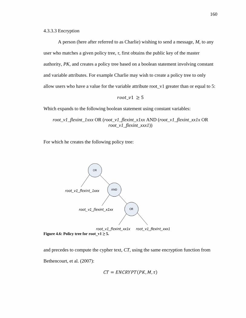
160
4.3.3.3 Encryption
A person (here after referred to as Charlie) wishing to send a message, M, to any
user who matches a given policy tree, τ, first obtains the public key of the master
authority, PK, and creates a policy tree based on a boolean statement involving constant
and variable attributes. For example Charlie may wish to create a policy tree to only
allow users who have a value for the variable attribute root_v1 greater than or equal to 5:
Which expands to the following boolean statement using constant variables:
root_v1_flexint_1xxx OR (root_v1_flexint_x1xx AND (root_v1_flexint_xx1x OR
root_v1_flexint_xxx1))
For which he creates the following policy tree:
Figure 4.6: Policy tree for root_v1 ≥ 5.
and precedes to compute the cypher text, CT, using the same encryption function from
Bethencourt, et al. (2007):
( )
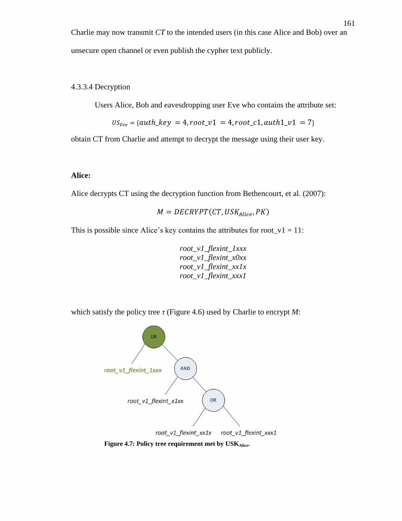
161
Charlie may now transmit CT to the intended users (in this case Alice and Bob) over an
unsecure open channel or even publish the cypher text publicly.
4.3.3.4 Decryption
Users Alice, Bob and eavesdropping user Eve who contains the attribute set:
obtain CT from Charlie and attempt to decrypt the message using their user key.
Alice:
Alice decrypts CT using the decryption function from Bethencourt, et al. (2007):
( )
This is possible since Alice’s key contains the attributes for root_v1 = 11:
root_v1_flexint_1xxx
root_v1_flexint_x0xx
root_v1_flexint_xx1x
root_v1_flexint_xxx1
which satisfy the policy tree τ (Figure 4.6) used by Charlie to encrypt M:
Figure 4.7: Policy tree requirement met by USKAlice.
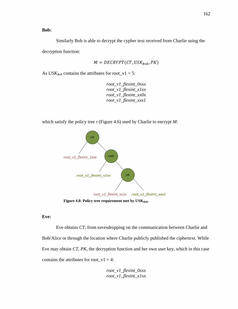
162
Bob:
Similarly Bob is able to decrypt the cypher text received from Charlie using the
decryption function:
( )
As USKBob contains the attributes for root_v1 = 5:
root_v1_flexint_0xxx
root_v1_flexint_x1xx
root_v1_flexint_xx0x
root_v1_flexint_xxx1
which satisfy the policy tree τ (Figure 4.6) used by Charlie to encrypt M:
Eve:
Eve obtains CT, from eavesdropping on the communication between Charlie and
Bob/Alice or through the location where Charlie publicly published the ciphertext. While
Eve may obtain CT, PK, the decryption function and her own user key, which in this case
contains the attributes for root_v1 = 4:
root_v1_flexint_0xxx
root_v1_flexint_x1xx
Figure 4.8: Policy tree requirement met by USKBob.
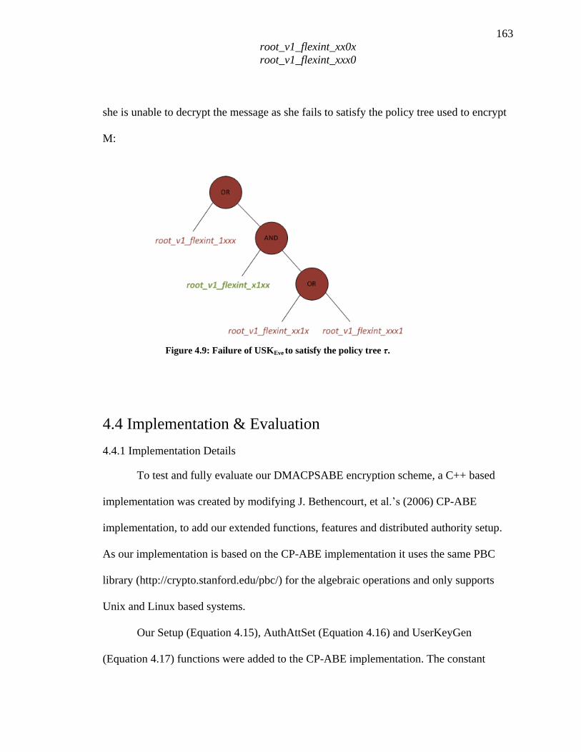
163
root_v1_flexint_xx0x
root_v1_flexint_xxx0
she is unable to decrypt the message as she fails to satisfy the policy tree used to encrypt
M:
4.4 Implementation & Evaluation
4.4.1 Implementation Details
To test and fully evaluate our DMACPSABE encryption scheme, a C++ based
implementation was created by modifying J. Bethencourt, et al.’s (2006) CP-ABE
implementation, to add our extended functions, features and distributed authority setup.
As our implementation is based on the CP-ABE implementation it uses the same PBC
library (http://crypto.stanford.edu/pbc/) for the algebraic operations and only supports
Unix and Linux based systems.
Our Setup (Equation 4.15), AuthAttSet (Equation 4.16) and UserKeyGen
(Equation 4.17) functions were added to the CP-ABE implementation. The constant
Figure 4.9: Failure of USKEve to satisfy the policy tree τ.
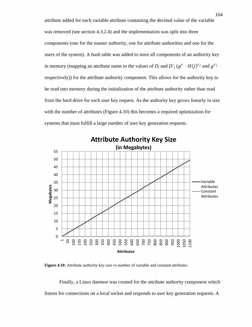
164
attribute added for each variable attribute containing the decimal value of the variable
was removed (see section 4.3.2.4) and the implementation was split into three
components (one for the master authority, one for attribute authorities and one for the
users of the system). A hash table was added to store all components of an authority key
in memory (mapping an attribute name to the values of Dj and D`j ( ( ) and
respectively)) for the attribute authority component. This allows for the authority key to
be read into memory during the initialization of the attribute authority rather than read
from the hard drive for each user key request. As the authority key grows linearly in size
with the number of attributes (Figure 4.10) this becomes a required optimization for
systems that must fulfill a large number of user key generation requests.
Figure 4.10: Attribute authority key size vs number of variable and constant attributes.
Finally, a Linux daemon was created for the attribute authority component which
listens for connections on a local socket and responds to user key generation requests. A
0
5
10
15
20
25
30
35
40
45
50
55
1
50
10
0
15
0
20
0
25
0
30
0
35
0
40
0
45
0
50
0
55
0
60
0
65
0
70
0
75
0
80
0
85
0
90
0
95
0
10
00
10
50
11
00
Me
gab
yte
s
Attributes
Attribute Authority Key Size (in Megabytes)
VariableAttributesConstantAttributes
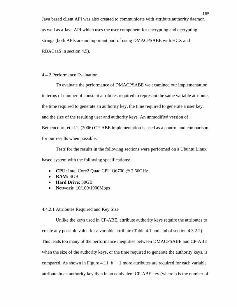
165
Java based client API was also created to communicate with attribute authority daemon
as well as a Java API which uses the user component for encrypting and decrypting
strings (both APIs are an important part of using DMACPSABE with HCX and
RBACaaS in section 4.5).
4.4.2 Performance Evaluation
To evaluate the performance of DMACPSABE we examined our implementation
in terms of number of constant attributes required to represent the same variable attribute,
the time required to generate an authority key, the time required to generate a user key,
and the size of the resulting user and authority keys. An unmodified version of
Bethencourt, et al.’s (2006) CP-ABE implementation is used as a control and comparison
for our results when possible.
Tests for the results in the following sections were performed on a Ubuntu Linux
based system with the following specifications:
CPU: Intel Core2 Quad CPU Q6700 @ 2.66GHz
RAM: 4GB
Hard Drive: 30GB
Network: 10/100/1000Mbps
4.4.2.1 Attributes Required and Key Size
Unlike the keys used in CP-ABE, attribute authority keys require the attributes to
create any possible value for a variable attribute (Table 4.1 and end of section 4.3.2.2).
This leads too many of the performance inequities between DMACPSABE and CP-ABE
when the size of the authority keys, or the time required to generate the authority keys, is
compared. As shown in Figure 4.11, more attributes are required for each variable
attribute in an authority key than in an equivalent CP-ABE key (where b is the number of
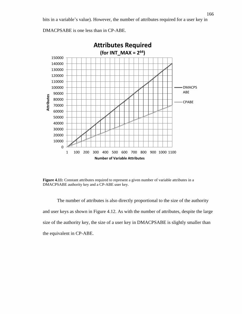
166
bits in a variable’s value). However, the number of attributes required for a user key in
DMACPSABE is one less than in CP-ABE.
Figure 4.11: Constant attributes required to represent a given number of variable attributes in a
DMACPSABE authority key and a CP-ABE user key.
The number of attributes is also directly proportional to the size of the authority
and user keys as shown in Figure 4.12. As with the number of attributes, despite the large
size of the authority key, the size of a user key in DMACPSABE is slightly smaller than
the equivalent in CP-ABE.
0
10000
20000
30000
40000
50000
60000
70000
80000
90000
100000
110000
120000
130000
140000
150000
1 100 200 300 400 500 600 700 800 900 1000 1100
Att
rib
ute
s
Number of Variable Attributes
Attributes Required (for INT_MAX = 264)
DMACPSABE
CPABE
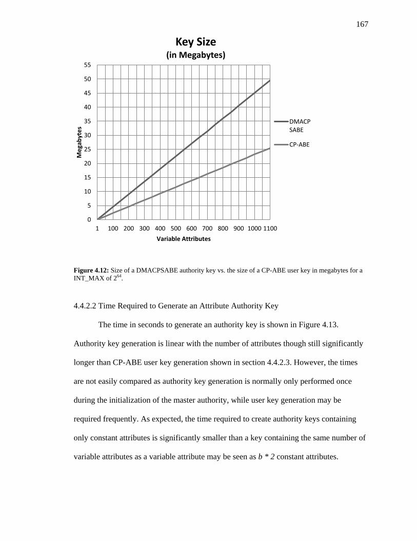
167
Figure 4.12: Size of a DMACPSABE authority key vs. the size of a CP-ABE user key in megabytes for a
INT_MAX of 264.
4.4.2.2 Time Required to Generate an Attribute Authority Key
The time in seconds to generate an authority key is shown in Figure 4.13.
Authority key generation is linear with the number of attributes though still significantly
longer than CP-ABE user key generation shown in section 4.4.2.3. However, the times
are not easily compared as authority key generation is normally only performed once
during the initialization of the master authority, while user key generation may be
required frequently. As expected, the time required to create authority keys containing
only constant attributes is significantly smaller than a key containing the same number of
variable attributes as a variable attribute may be seen as b * 2 constant attributes.
0
5
10
15
20
25
30
35
40
45
50
55
1 100 200 300 400 500 600 700 800 900 1000 1100
Me
gab
yte
s
Variable Attributes
Key Size (in Megabytes)
DMACPSABE
CP-ABE
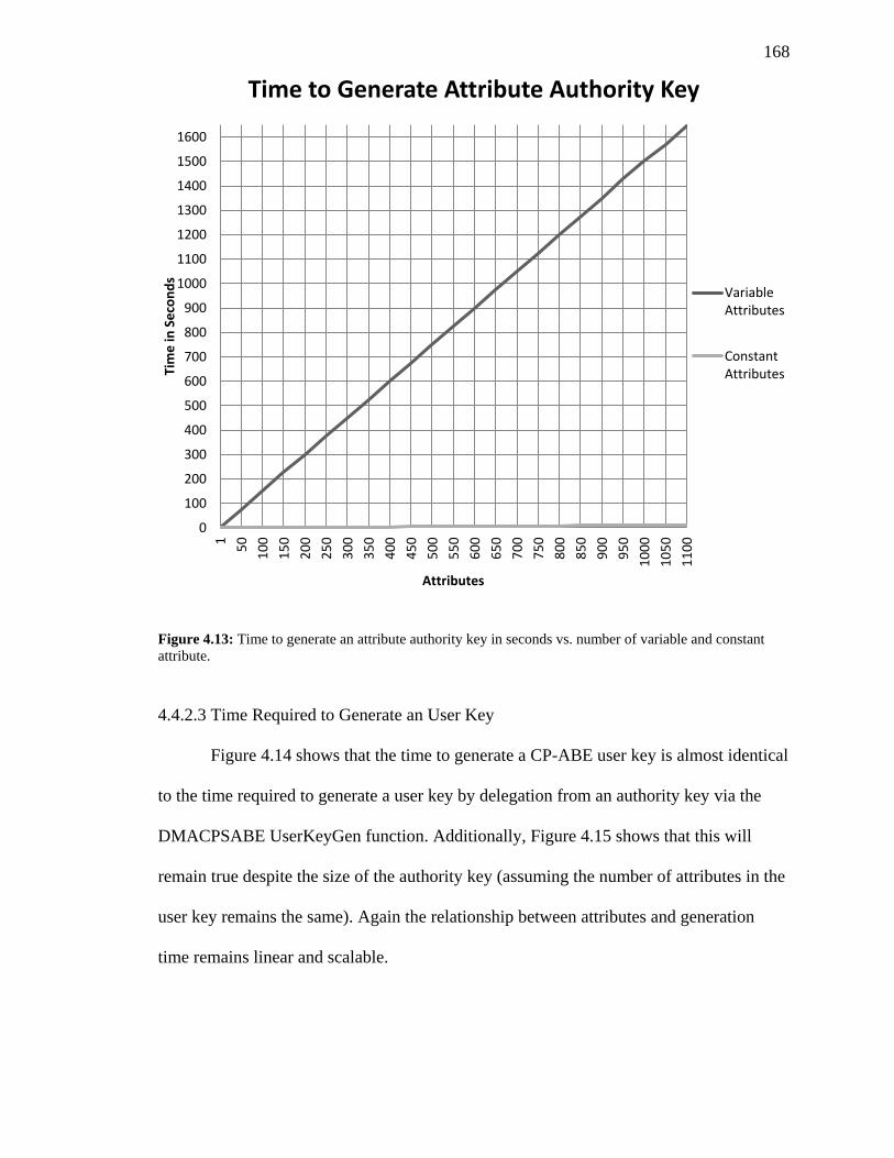
168
Figure 4.13: Time to generate an attribute authority key in seconds vs. number of variable and constant
attribute.
4.4.2.3 Time Required to Generate an User Key
Figure 4.14 shows that the time to generate a CP-ABE user key is almost identical
to the time required to generate a user key by delegation from an authority key via the
DMACPSABE UserKeyGen function. Additionally, Figure 4.15 shows that this will
remain true despite the size of the authority key (assuming the number of attributes in the
user key remains the same). Again the relationship between attributes and generation
time remains linear and scalable.
0
100
200
300
400
500
600
700
800
900
1000
1100
1200
1300
1400
1500
1600
1
50
10
0
15
0
20
0
25
0
30
0
35
0
40
0
45
0
50
0
55
0
60
0
65
0
70
0
75
0
80
0
85
0
90
0
95
0
10
00
10
50
11
00
Tim
e in
Se
con
ds
Attributes
Time to Generate Attribute Authority Key
VariableAttributes
ConstantAttributes
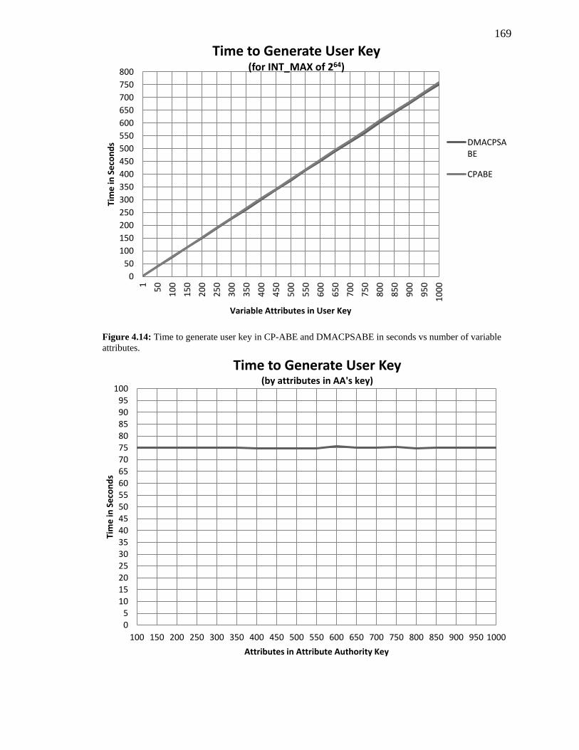
169
Figure 4.14: Time to generate user key in CP-ABE and DMACPSABE in seconds vs number of variable
attributes.
0
50
100
150
200
250
300
350
400
450
500
550
600
650
700
750
800
1
50
10
0
15
0
20
0
25
0
30
0
35
0
40
0
45
0
50
0
55
0
60
0
65
0
70
0
75
0
80
0
85
0
90
0
95
0
10
00
Tim
e in
Se
con
ds
Variable Attributes in User Key
Time to Generate User Key (for INT_MAX of 264)
DMACPSABE
CPABE
05
101520253035404550556065707580859095
100
100 150 200 250 300 350 400 450 500 550 600 650 700 750 800 850 900 950 1000
Tim
e in
Se
con
ds
Attributes in Attribute Authority Key
Time to Generate User Key (by attributes in AA's key)
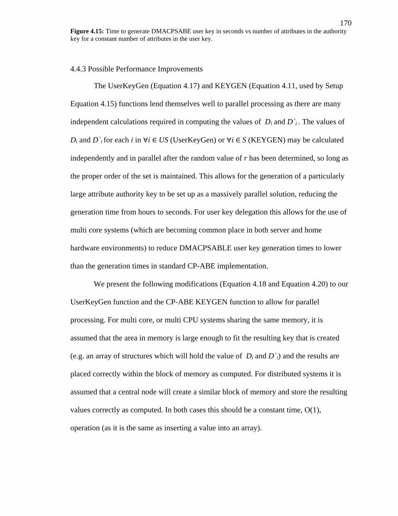
170 Figure 4.15: Time to generate DMACPSABE user key in seconds vs number of attributes in the authority
key for a constant number of attributes in the user key.
4.4.3 Possible Performance Improvements
The UserKeyGen (Equation 4.17) and KEYGEN (Equation 4.11, used by Setup
Equation 4.15) functions lend themselves well to parallel processing as there are many
independent calculations required in computing the values of Di and D`i . The values of
Di and D`i for each i in i US (UserKeyGen) or i S (KEYGEN) may be calculated
independently and in parallel after the random value of r has been determined, so long as
the proper order of the set is maintained. This allows for the generation of a particularly
large attribute authority key to be set up as a massively parallel solution, reducing the
generation time from hours to seconds. For user key delegation this allows for the use of
multi core systems (which are becoming common place in both server and home
hardware environments) to reduce DMACPSABLE user key generation times to lower
than the generation times in standard CP-ABE implementation.
We present the following modifications (Equation 4.18 and Equation 4.20) to our
UserKeyGen function and the CP-ABE KEYGEN function to allow for parallel
processing. For multi core, or multi CPU systems sharing the same memory, it is
assumed that the area in memory is large enough to fit the resulting key that is created
(e.g. an array of structures which will hold the value of Di and D`i) and the results are
placed correctly within the block of memory as computed. For distributed systems it is
assumed that a central node will create a similar block of memory and store the resulting
values correctly as computed. In both cases this should be a constant time, O(1),
operation (as it is the same as inserting a value into an array).
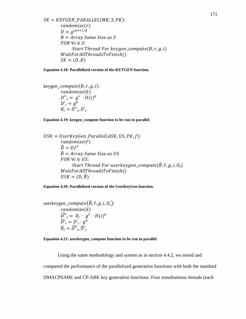
171
( ) ( )
( ) ⁄
( )
()
( )
Equation 4.18: Parallelized version of the KEYGEN function.
keygen_ ( ) ( )
( )
Equation 4.19: keygen_compute function to be run in parallel.
( ) ( )
( )
()
( )
Equation 4.20: Parallelized version of the UserKeyGen function.
userkeygen_ ( )
( )
( )
Equation 4.21: userkeygen_compute function to be run in parallel.
Using the same methodology and system as in section 4.4.2, we tested and
compared the performance of the parallelized generation functions with both the standard
DMACPSABE and CP-ABE key generation functions. Four simultaneous threads (each
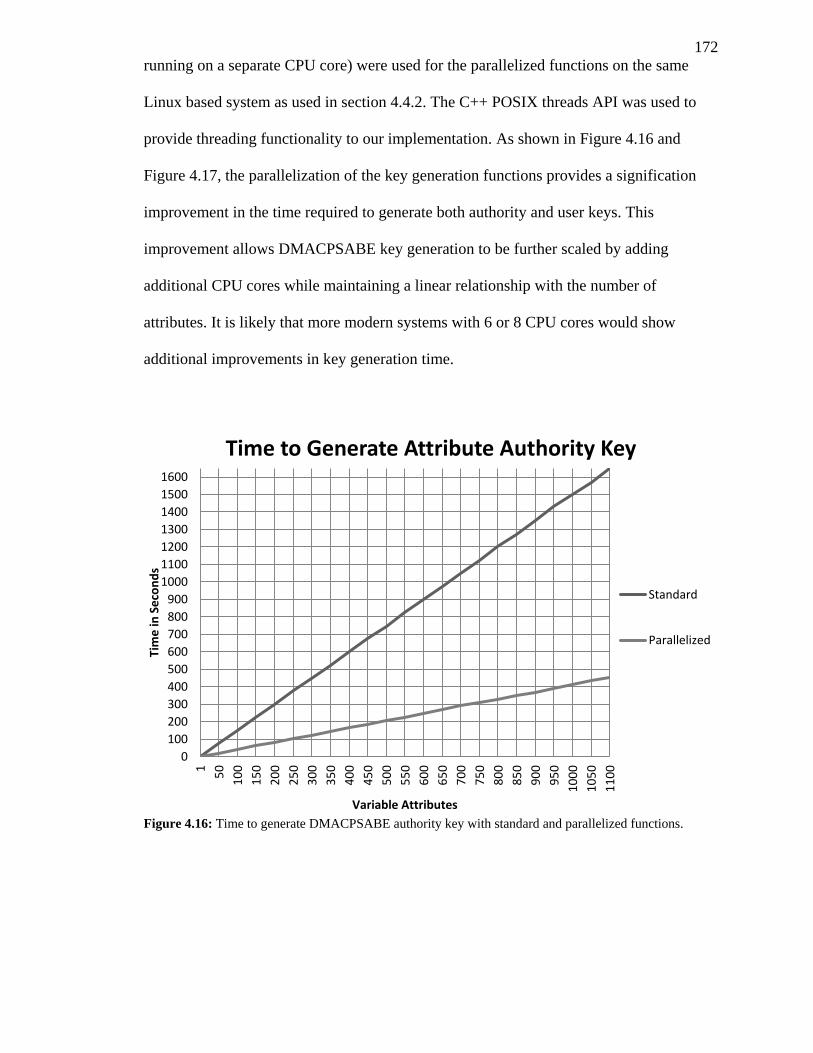
172
running on a separate CPU core) were used for the parallelized functions on the same
Linux based system as used in section 4.4.2. The C++ POSIX threads API was used to
provide threading functionality to our implementation. As shown in Figure 4.16 and
Figure 4.17, the parallelization of the key generation functions provides a signification
improvement in the time required to generate both authority and user keys. This
improvement allows DMACPSABE key generation to be further scaled by adding
additional CPU cores while maintaining a linear relationship with the number of
attributes. It is likely that more modern systems with 6 or 8 CPU cores would show
additional improvements in key generation time.
Figure 4.16: Time to generate DMACPSABE authority key with standard and parallelized functions.
0
100
200
300
400
500
600
700
800
900
1000
1100
1200
1300
1400
1500
1600
1
50
10
0
15
0
20
0
25
0
30
0
35
0
40
0
45
0
50
0
55
0
60
0
65
0
70
0
75
0
80
0
85
0
90
0
95
0
10
00
10
50
11
00
Tim
e in
Se
con
ds
Variable Attributes
Time to Generate Attribute Authority Key
Standard
Parallelized
173
Figure 4.17: Time to generate a DMACPSABE or CP-ABE user key with standard and parallelized
functions.
4.4.4 Security
As the encryption and decryption algorithms used in DMACPSABE remain the
same as presented in Bethencourt, et al. (2007), the security of DMACPSABE may also
be proven secure under the generic bilinear group model (Boneh, Boyen, & Goh, 2005)
(as is shown in appendix A of Bethencourt, et al. (2007) for the decryption and
encryption functions). As with Bethencourt, et al. (2007) and with Boneh and Franklin
(2007)’s schemes, DMACPSABE can be extended to be secure against a chosen
ciphertext attack by applying the techniques from Fujisaki and Okamoto (1999).
DMACPSABE also provides a level of privacy in addition to that of CP-ABE by
obscuring the names of the attributes in the system. In the CP-ABE scheme, the policy
under which a given plain text is encrypted is attached, in plain text, to the ciphertext.
This policy (containing multiple plain text attribute names) may inadvertently leak
0
50
100
150
200
250
300
350
400
450
500
550
600
650
700
750
1
50
10
0
15
0
20
0
25
0
30
0
35
0
40
0
45
0
50
0
55
0
60
0
65
0
70
0
75
0
80
0
85
0
90
0
95
0
10
00
Tim
e in
Se
con
ds
Variable Attributes in User Key
Time to Generate User Key
DMACPSABE
ParallelizedDMACPSABE
CPABE
174
additional information about the contents of the ciphertext. For example, if a health
record is encrypted with a policy such as “is_doctor OR is_ chemotherapy_technician”, it
is leaked that the record may have something to do with chemotherapy as the attribute
“is_ chemotherapy_technician” is involved.
4.6 Conclusions
This chapter introduces the DMACPSABE scheme for providing CP-ABE in a
disturbed form where multiple authorities are granted a set of constant and variable
attributes which they may further delegate to their users. Some subset of these attributes
may be shared with other authorities such that access policies may be created that allow
foreign users to decrypt documents. Additionally, a “not equals” operation is added to
CP-ABE as well as a means for creating policies based on the user’s origin (i.e. which
attribute authority delegated their key). Details on how revocation and expiration are
enforced are discussed as well as how human readable attributes may be provided and
how attribute authorities may be added or removed.
The performance of a prototype implementation based on CP-ABE was evaluated
and found to scale linearly with the number of attributes. An additional improvement to
the key generation and delegation algorithms to support distributed processing (e.g. on
multiple CPU cores) was presented which further improved the performance of
DMACPSABE to the point of matching the original CP-ABE implementation. The
proceeding chapter gives details on how DMACPSABE may be used with the RBACaaS
model to enforce role based access policies and discusses some future areas of work for
DMACPSABE.
175
Chapter 5
5 Conclusions
5.1 Putting it all Together
When combined, the HCX, RBACaaS, RBSSO and DMACPSABE components
create a system for securely sharing EHRs on an untrusted public cloud. However, to
fully integrate these components there are several considerations and issues that must be
addressed. This section gives additional details on how theses sub-systems may be
combined and an overview of the overall system they create.
5.1.1 RBACaaS Integration with DMACPSABE
To integrate the role based access control policies offered by RBACaaS
with the DMACPSABE scheme (such that role based policies may be used to encrypt
documents rather than Boolean statements involving attributes) it is first necessary to
map both the permissions and user parameters to attribute names (as shown in the
modified RBACaaS model in Figure 5.2). Each permission used to protect encryptable
objects is mapped to a unique constant attribute devoted solely to that permission, while
every user parameter that is involved in conditions which effect the protection of
encryptable objects is mapped to a variable attribute (also devoted solely to that
parameter). This mapping is performed at creation of the parameter or permission and the
attribute is assigned to the same domain as the parameter or permission.
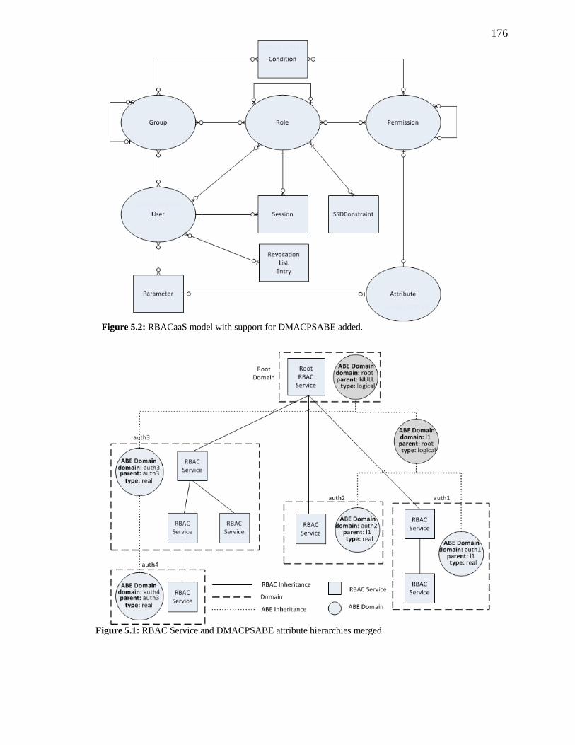
176
Figure 5.1: RBAC Service and DMACPSABE attribute hierarchies merged.
Figure 5.2: RBACaaS model with support for DMACPSABE added.
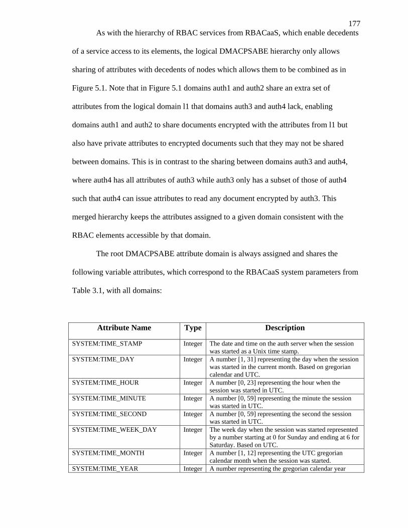
177
As with the hierarchy of RBAC services from RBACaaS, which enable decedents
of a service access to its elements, the logical DMACPSABE hierarchy only allows
sharing of attributes with decedents of nodes which allows them to be combined as in
Figure 5.1. Note that in Figure 5.1 domains auth1 and auth2 share an extra set of
attributes from the logical domain l1 that domains auth3 and auth4 lack, enabling
domains auth1 and auth2 to share documents encrypted with the attributes from l1 but
also have private attributes to encrypted documents such that they may not be shared
between domains. This is in contrast to the sharing between domains auth3 and auth4,
where auth4 has all attributes of auth3 while auth3 only has a subset of those of auth4
such that auth4 can issue attributes to read any document encrypted by auth3. This
merged hierarchy keeps the attributes assigned to a given domain consistent with the
RBAC elements accessible by that domain.
The root DMACPSABE attribute domain is always assigned and shares the
following variable attributes, which correspond to the RBACaaS system parameters from
Table 3.1, with all domains:
Attribute Name Type Description
SYSTEM:TIME_STAMP Integer The date and time on the auth server when the session
was started as a Unix time stamp.
SYSTEM:TIME_DAY Integer A number [1, 31] representing the day when the session
was started in the current month. Based on gregorian
calendar and UTC.
SYSTEM:TIME_HOUR Integer A number [0, 23] representing the hour when the
session was started in UTC.
SYSTEM:TIME_MINUTE Integer A number [0, 59] representing the minute the session
was started in UTC.
SYSTEM:TIME_SECOND Integer A number [0, 59] representing the second the session
was started in UTC.
SYSTEM:TIME_WEEK_DAY Integer The week day when the session was started represented
by a number starting at 0 for Sunday and ending at 6 for
Saturday. Based on UTC.
SYSTEM:TIME_MONTH Integer A number [1, 12] representing the UTC gregorian
calendar month when the session was started.
SYSTEM:TIME_YEAR Integer A number representing the gregorian calendar year
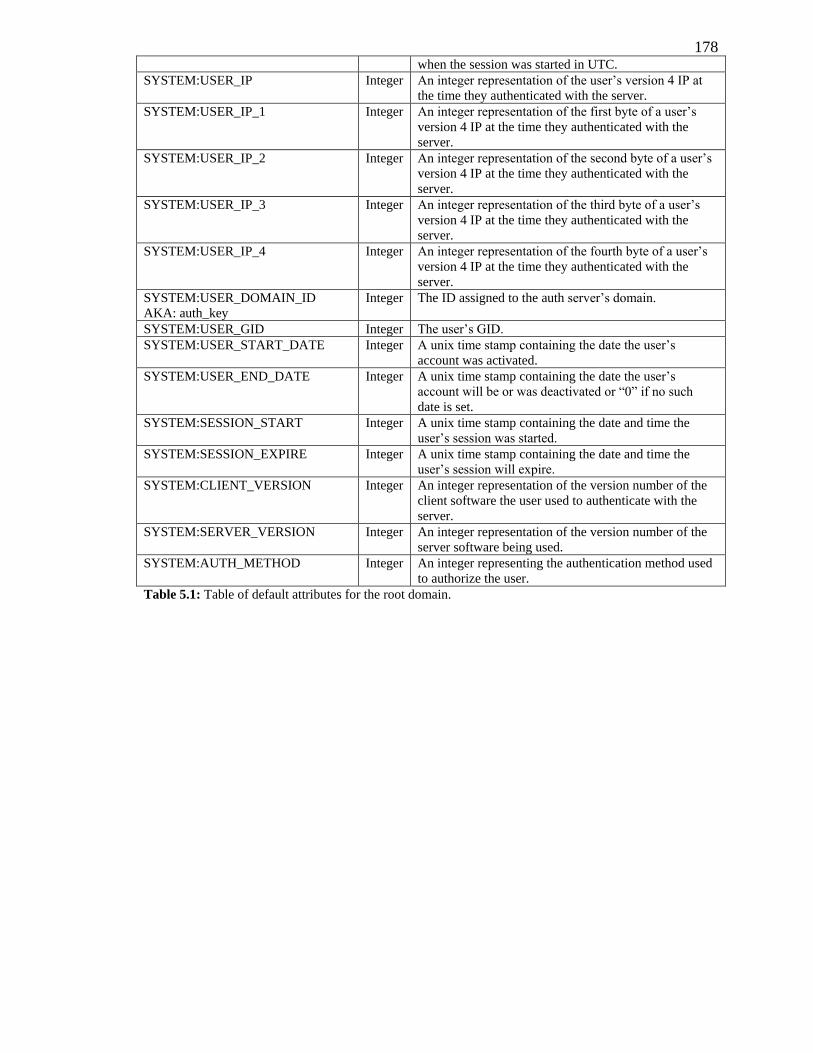
178 when the session was started in UTC.
SYSTEM:USER_IP Integer An integer representation of the user’s version 4 IP at
the time they authenticated with the server.
SYSTEM:USER_IP_1 Integer An integer representation of the first byte of a user’s
version 4 IP at the time they authenticated with the
server.
SYSTEM:USER_IP_2 Integer An integer representation of the second byte of a user’s
version 4 IP at the time they authenticated with the
server.
SYSTEM:USER_IP_3 Integer An integer representation of the third byte of a user’s
version 4 IP at the time they authenticated with the
server.
SYSTEM:USER_IP_4 Integer An integer representation of the fourth byte of a user’s
version 4 IP at the time they authenticated with the
server.
SYSTEM:USER_DOMAIN_ID
AKA: auth_key
Integer The ID assigned to the auth server’s domain.
SYSTEM:USER_GID Integer The user’s GID.
SYSTEM:USER_START_DATE Integer A unix time stamp containing the date the user’s
account was activated.
SYSTEM:USER_END_DATE Integer A unix time stamp containing the date the user’s
account will be or was deactivated or “0” if no such
date is set.
SYSTEM:SESSION_START Integer A unix time stamp containing the date and time the
user’s session was started.
SYSTEM:SESSION_EXPIRE Integer A unix time stamp containing the date and time the
user’s session will expire.
SYSTEM:CLIENT_VERSION Integer An integer representation of the version number of the
client software the user used to authenticate with the
server.
SYSTEM:SERVER_VERSION Integer An integer representation of the version number of the
server software being used.
SYSTEM:AUTH_METHOD Integer An integer representing the authentication method used
to authorize the user.
Table 5.1: Table of default attributes for the root domain.
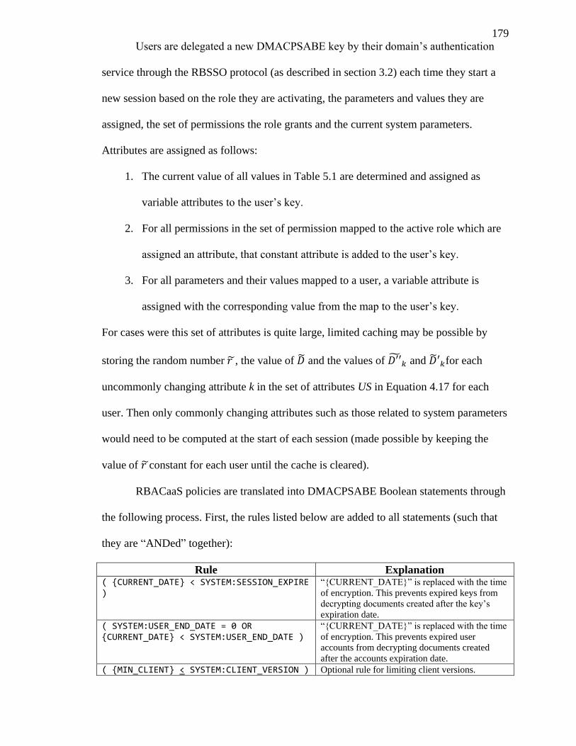
179
Users are delegated a new DMACPSABE key by their domain’s authentication
service through the RBSSO protocol (as described in section 3.2) each time they start a
new session based on the role they are activating, the parameters and values they are
assigned, the set of permissions the role grants and the current system parameters.
Attributes are assigned as follows:
1. The current value of all values in Table 5.1 are determined and assigned as
variable attributes to the user’s key.
2. For all permissions in the set of permission mapped to the active role which are
assigned an attribute, that constant attribute is added to the user’s key.
3. For all parameters and their values mapped to a user, a variable attribute is
assigned with the corresponding value from the map to the user’s key.
For cases were this set of attributes is quite large, limited caching may be possible by
storing the random number , the value of and the values of and for each
uncommonly changing attribute k in the set of attributes US in Equation 4.17 for each
user. Then only commonly changing attributes such as those related to system parameters
would need to be computed at the start of each session (made possible by keeping the
value of constant for each user until the cache is cleared).
RBACaaS policies are translated into DMACPSABE Boolean statements through
the following process. First, the rules listed below are added to all statements (such that
they are “ANDed” together):
Rule Explanation ( {CURRENT_DATE} < SYSTEM:SESSION_EXPIRE )
“{CURRENT_DATE}” is replaced with the time
of encryption. This prevents expired keys from
decrypting documents created after the key’s
expiration date.
( SYSTEM:USER_END_DATE = 0 OR {CURRENT_DATE} < SYSTEM:USER_END_DATE )
“{CURRENT_DATE}” is replaced with the time
of encryption. This prevents expired user
accounts from decrypting documents created
after the accounts expiration date.
( {MIN_CLIENT} < SYSTEM:CLIENT_VERSION ) Optional rule for limiting client versions.
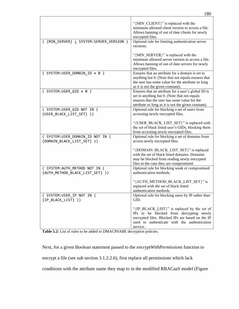
180
“{MIN_CLIENT}” is replaced with the
minimum allowed client version to access a file.
Allows banning of out of date clients for newly
encrypted files.
( {MIN_SERVER} < SYSTEM:SERVER_VERSION ) Optional rule for limiting authentication server
versions.
“{MIN_SERVER}” is replaced with the
minimum allowed server version to access a file.
Allows banning of out of date servers for newly
encrypted files.
( SYSTEM:USER_DOMAIN_ID ≠ 0 ) Ensures that an attribute for a domain is set to
anything but 0. (Note that not equals ensures that
the user has some value for the attribute so long
as it is not the given constant).
( SYSTEM:USER_GID ≠ 0 ) Ensures that an attribute for a user’s global ID is
set to anything but 0. (Note that not equals
ensures that the user has some value for the
attribute so long as it is not the given constant).
( SYSTEM:USER_GID NOT IN ( {USER_BLACK_LIST_SET} ))
Optional rule for blocking a set of users from
accessing newly encrypted files.
“{USER_BLACK_LIST_SET}” is replaced with
the set of black listed user’s GIDs, blocking them
from accessing newly encrypted files.
( SYSTEM:USER_DOMAIN_ID NOT IN ( {DOMAIN_BLACK_LIST_SET} ))
Optional rule for blocking a set of domains from
access newly encrypted files.
“{DOMAIN_BLACK_LIST_SET}” is replaced
with the set of black listed domains. Domains
may be blocked from reading newly encrypted
files in the case they are compromised.
( SYSTEM:AUTH_METHOD NOT IN ( {AUTH_METHOD_BLACK_LIST_SET} ))
Optional rule for blocking weak or compromised
authentication methods.
“{AUTH_METHOD_BLACK_LIST_SET}” is
replaced with the set of black listed
authentication methods.
( SYSTEM:USER_IP NOT IN ( {IP_BLACK_LIST} ))
Optional rule for blocking users by IP rather than
GID.
“{IP_BLACK_LIST}” is replaced by the set of
IPs to be blocked from decrypting newly
encrypted files. Blocked IPs are based on the IP
used to authenticate with the authentication
service.
Table 5.2: List of rules to be added to DMACPSABE decryption policies.
Next, for a given Boolean statement passed to the encryptWithPermissions function to
encrypt a file (see sub section 3.1.2.2.6), first replace all permissions which lack
conditions with the attribute name they map to in the modified RBACaaS model (Figure
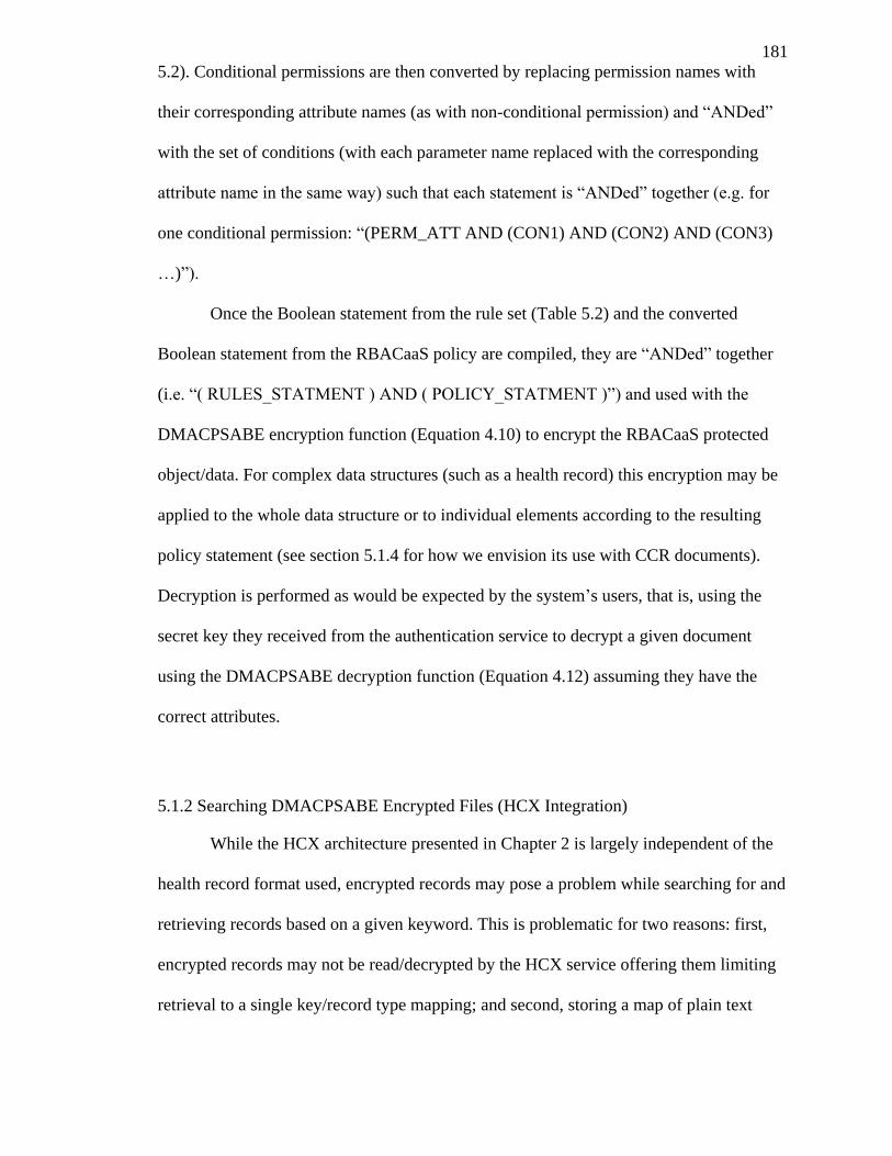
181
5.2). Conditional permissions are then converted by replacing permission names with
their corresponding attribute names (as with non-conditional permission) and “ANDed”
with the set of conditions (with each parameter name replaced with the corresponding
attribute name in the same way) such that each statement is “ANDed” together (e.g. for
one conditional permission: “(PERM_ATT AND (CON1) AND (CON2) AND (CON3)
…)”).
Once the Boolean statement from the rule set (Table 5.2) and the converted
Boolean statement from the RBACaaS policy are compiled, they are “ANDed” together
(i.e. “( RULES_STATMENT ) AND ( POLICY_STATMENT )”) and used with the
DMACPSABE encryption function (Equation 4.10) to encrypt the RBACaaS protected
object/data. For complex data structures (such as a health record) this encryption may be
applied to the whole data structure or to individual elements according to the resulting
policy statement (see section 5.1.4 for how we envision its use with CCR documents).
Decryption is performed as would be expected by the system’s users, that is, using the
secret key they received from the authentication service to decrypt a given document
using the DMACPSABE decryption function (Equation 4.12) assuming they have the
correct attributes.
5.1.2 Searching DMACPSABE Encrypted Files (HCX Integration)
While the HCX architecture presented in Chapter 2 is largely independent of the
health record format used, encrypted records may pose a problem while searching for and
retrieving records based on a given keyword. This is problematic for two reasons: first,
encrypted records may not be read/decrypted by the HCX service offering them limiting
retrieval to a single key/record type mapping; and second, storing a map of plain text
182
keywords to encrypted records (or even sending the keywords to the service) would leak
information about the contents of that record. Several solutions to this problem (searching
encrypted files on remote systems) already exist and have been explored in detail in
recent literature (Chang & Mitzenmacher, 2005) (Li, Wang, Wang, Cao, Ren, & Lou,
2010) (Wang, Cao, Li, Ren, & Lou, 2010) (Ballard, Green, Medeiros, & Monrose, 2005).
As many of these solutions are independent of the encryption system used and suitable
for (or in many cases made for) searching encrypted files on remote systems (such that
the remote system may not determine the keyword or hints at the files contents) we leave
this as an implementation detail for practical systems and consider it out of the scope of
the presented research. In cases where an additional key or map is required to be
distributed to the system’s clients, to enable search functionality, the authentication
service may be extended to provide this as it is isolated from the cloud and considered
secure.
For our prototype, a trivial, but efficient solution of simply hashing each keyword
with a salt was used to provide some level of obscurity to keywords. In this method every
encrypted element of a record was mapped to a set of hashes paired with an integer
representing the hash’s relevance to that cipher text. When a user encrypted an element of
a record, they would be responsible for generating the hashes and relevance integer based
on some metric such as word count, and including the map in the appropriate plain text
section of the record. When requesting a list of records based on a given keyword (or set
of keywords), the user would compute the hash of the keyword + salt and send it in the
request to the HCX service. The HCX service would respond with a list of the top records
containing the hash ordered by total relevance. While this method provides a simple
means of performing the search, it is not correlation-resistant and fails to stop a malicious
cloud provider or system administrator from finding identifying common keyword hashes
183
either by analyzing their use or guessing words that might appear in a health record and
generating the corresponding hash (assuming they have the correct salt). As such this
method is not recommended for a practical implementation on an untrusted cloud.
5.1.3 HCX Integration with RBACaaS and RBSSO
The main task in integrating HCX with the RBACaaS system is simply creating
permissions for each task a user may perform and using the service client API provided
by RBACaaS to check if a requesting user has permission to perform the request. Per file
permissions may be embedded in a given document (as described in section 5.1.4) by
listing the Boolean permission statements for different levels of access within that
document and only allowing authorized users to update that section of the file (i.e.
rejecting requests which change the line without the user having the correct permission in
their authtoken). When a record is requested, its permission statement may be checked
against the user’s active role’s permission set and the request may be accepted or rejected
accordingly.
Integration with the RBSSO protocol may be accomplished by having each
request to an HCX service accept a Request Token (as detailed in section 3.2.2.4) and
having a simple HCX service for authenticating users as explained in section 3.2.2.4 (i.e.
via an authtoken from the domain’s authentication service). The HCX service may then
examine the user’s authtoken to determine the permission set their active role grants and
the conditions on those permissions (resulting from group conditions). Additionally, the
machine instance running HCX may occasionally query a central trusted third party (e.g.
the service controller or authentication services) for revocation lists of users, domains,
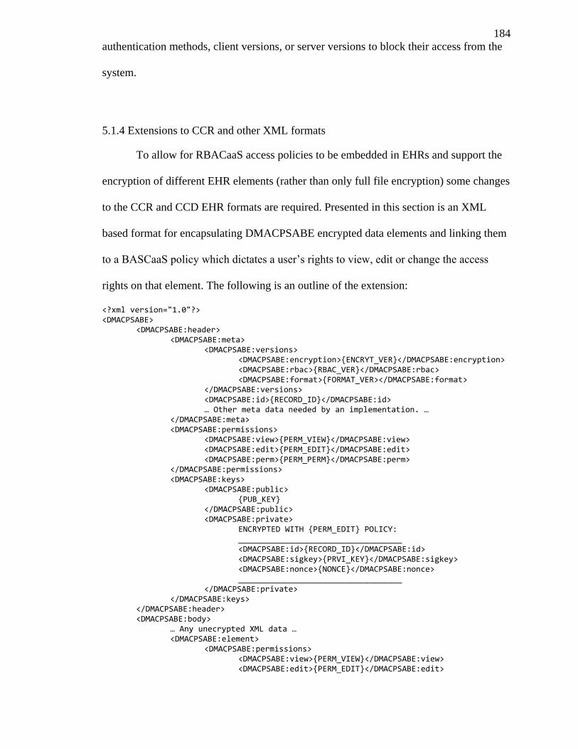
184
authentication methods, client versions, or server versions to block their access from the
system.
5.1.4 Extensions to CCR and other XML formats
To allow for RBACaaS access policies to be embedded in EHRs and support the
encryption of different EHR elements (rather than only full file encryption) some changes
to the CCR and CCD EHR formats are required. Presented in this section is an XML
based format for encapsulating DMACPSABE encrypted data elements and linking them
to a BASCaaS policy which dictates a user’s rights to view, edit or change the access
rights on that element. The following is an outline of the extension:
<?xml version="1.0"?> <DMACPSABE> <DMACPSABE:header> <DMACPSABE:meta> <DMACPSABE:versions> <DMACPSABE:encryption>{ENCRYT_VER}</DMACPSABE:encryption> <DMACPSABE:rbac>{RBAC_VER}</DMACPSABE:rbac> <DMACPSABE:format>{FORMAT_VER></DMACPSABE:format>
</DMACPSABE:versions> <DMACPSABE:id>{RECORD_ID}</DMACPSABE:id> … Other meta data needed by an implementation. … </DMACPSABE:meta> <DMACPSABE:permissions> <DMACPSABE:view>{PERM_VIEW}</DMACPSABE:view> <DMACPSABE:edit>{PERM_EDIT}</DMACPSABE:edit> <DMACPSABE:perm>{PERM_PERM}</DMACPSABE:perm> </DMACPSABE:permissions> <DMACPSABE:keys> <DMACPSABE:public> {PUB_KEY} </DMACPSABE:public> <DMACPSABE:private> ENCRYPTED WITH {PERM_EDIT} POLICY: ___________________________________ <DMACPSABE:id>{RECORD_ID}</DMACPSABE:id> <DMACPSABE:sigkey>{PRVI_KEY}</DMACPSABE:sigkey> <DMACPSABE:nonce>{NONCE}</DMACPSABE:nonce> ___________________________________ </DMACPSABE:private> </DMACPSABE:keys>
</DMACPSABE:header> <DMACPSABE:body>
… Any unecrypted XML data … <DMACPSABE:element> <DMACPSABE:permissions> <DMACPSABE:view>{PERM_VIEW}</DMACPSABE:view> <DMACPSABE:edit>{PERM_EDIT}</DMACPSABE:edit>
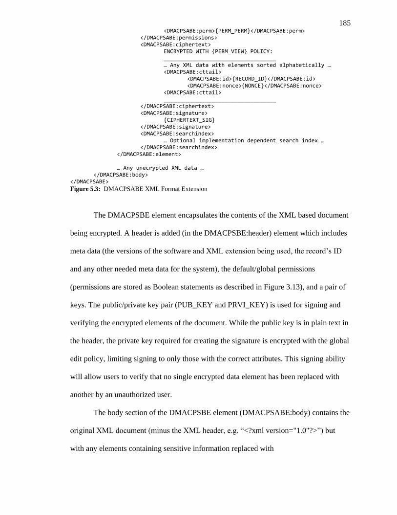
185 <DMACPSABE:perm>{PERM_PERM}</DMACPSABE:perm> </DMACPSABE:permissions> <DMACPSABE:ciphertext>
ENCRYPTED WITH {PERM_VIEW} POLICY: ___________________________________ … Any XML data with elements sorted alphabetically …
<DMACPSABE:cttail> <DMACPSABE:id>{RECORD_ID}</DMACPSABE:id>
<DMACPSABE:nonce>{NONCE}</DMACPSABE:nonce> <DMACPSABE:cttail>
___________________________________ </DMACPSABE:ciphertext> <DMACPSABE:signature> {CIPHERTEXT_SIG}
</DMACPSABE:signature> <DMACPSABE:searchindex> … Optional implementation dependent search index … </DMACPSABE:searchindex>
</DMACPSABE:element>
… Any unecrypted XML data … </DMACPSABE:body>
</DMACPSABE>
Figure 5.3: DMACPSABE XML Format Extension
The DMACPSBE element encapsulates the contents of the XML based document
being encrypted. A header is added (in the DMACPSBE:header) element which includes
meta data (the versions of the software and XML extension being used, the record’s ID
and any other needed meta data for the system), the default/global permissions
(permissions are stored as Boolean statements as described in Figure 3.13), and a pair of
keys. The public/private key pair (PUB_KEY and PRVI_KEY) is used for signing and
verifying the encrypted elements of the document. While the public key is in plain text in
the header, the private key required for creating the signature is encrypted with the global
edit policy, limiting signing to only those with the correct attributes. This signing ability
will allow users to verify that no single encrypted data element has been replaced with
another by an unauthorized user.
The body section of the DMACPSBE element (DMACPSABE:body) contains the
original XML document (minus the XML header, e.g. “<?xml version="1.0"?>”) but
with any elements containing sensitive information replaced with
186
DMACPSABE:element. DMACPSABE:element contains an optional permissions
element (DMACPSABE:element) which overrides the documents default permissions, a
DMACPSABE:ciphertext element that contains the encrypted XML element, a
DMACPSABE:signature element containing a signature of the XML element using the
PRIV_KEY from the header, and an optional DMACPSABE:searchindex element which
contains a protected index of keywords relating to the encrypted text (as discussed in
5.1.2). Before encryption of the protected XML element, the DMACPSABE:cttail
element is appended to the plain text such that the authenticity of the text may be verified
(i.e. that the nonce matches the encrypted nonce in the header and the record ID matches
the ID used to retrieve the record).
For the case of a HCX service, the default view access policy in the header
determines if a user may request the file. The edit policy of a given section determines if
a user may update that section. The perm policy of a given section determines if a user
may change the permissions of that section or the policy under which the data is
encrypted. These policies are enforced by the HCX service (using the RBACaaS service
client API), however, the ability to view a protected part of a file (i.e. decrypt it) is
enforced by the DMACPSABE encryption scheme (such that a user must have a key
granted by an attribute authority that meets the access policy used during encryption)
using the view policy for a given DMACPSABE:element. The creation of the original
policies embedded in the document is the responsibility of the document’s original
creator (as is the generation of the private/public signing key pair and nonce). However, it
would be trivial to create an HCX service such that a minimal access policy is enforced
(e.g. by rejecting weak policies based on some set criteria or policies that do not enforce
rules detailed in section 5.1.1). In a real world implementation, the appropriate default
policies would likely be encoded into the client application, or document creation would
187
be performed by a policy engine capable of converting existing health records and/or
automatically determining the correct policy (as described in the work by Akinyele, et al.
(2010)).
While this format protects a given record from a malicious cloud provider
changing a single protected element (or any number of elements so long as not all
encrypted elements including the private key in the header), it does not protect against the
provider completely changing the whole document (and generating their own private key
and nonce). However, such an attack would not likely succeed because the provider
would have no knowledge of the contents of the document or to whom it may pertain,
making such changes immediately noticeable. For example, if an EHR was requested
with an ID corresponding to John Doe, but the received EHR contained a fake record for
the patient Joe Bloggs (note that it would not be possible to switch the EHR with another
real EHR in the system as the record ID is included in the ciphertext) it would be
immediately evident that the EHR had been compromised. Extending the DMACPSABE
scheme to also support signing of documents would provide a potential fix for this
problem (and is listed among the future areas of work in section 5.2), as would having the
authentication authority distributing signing keys to users such that they may be used to
authenticate documents.
5.1.5 System Overview
The diagram presented in Figure 5.4 displays an overview of the complete system
with all components functioning together. For any given domain, the RBAC service,
attribute authority and authentication service would likely be combined in one server
software package in an implementation of the system that connects to an existing
188
database with user credentials for the organization (e.g. LDAP{_footer_}). The trusted
third party (which may be a domain trusted by the other domains to perform the role or
an completely independent entity) would only primarily be responsible for running the
service controller which dynamically creates and destroys the machine instances running
the HCX services according to current levels of demand. Additionally, the trusted third
party is responsible for the initial creation of the DMACPSABE authority keys, initial
creation of the root roles and permissions and for publishing the public keys and
revocation lists.
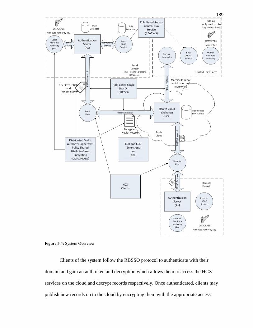
189
Figure 5.4: System Overview
Clients of the system follow the RBSSO protocol to authenticate with their
domain and gain an authtoken and decryption which allows them to access the HCX
services on the cloud and decrypt records respectively. Once authenticated, clients may
publish new records on to the cloud by encrypting them with the appropriate access
190
policy and uploading them to a HCX service. Reversely, clients may obtain records by
requesting the encrypted file from a HCX service and decrypting the elements of the
record for which they have access. Updates to records are performed by requesting the
record, decrypting the relevant section, making the desired changes, generating a new
keyword map (if applicable for the search method being used), and encrypting the section
with the same access policy (a different access policy may only be used if the user has the
correct permissions active), and finally reuploading the record to the HCX service. If the
HCX service determines that the client has the appropriate permissions active for the
given changes, the record is updated.
5.2 Future Work
While the presented research is a step towards cloud privacy and security for
EHRs, there are still many areas for improvement, future research, and open problems to
be solved. This section identifies several of these areas and suggests potential directions
for future research.
5.2.1 Automated Policy Discovery/Creation
While RBACaaS, RBSSO and DMACPSABE provide the tools for creating and
enforcing role based access policies, it is still left to the policy administrator to ensure the
proper policies are created for a given origination’s needs and that they are correctly
applied. Automating the process of policy discovery based on an overall set of criteria for
an organization would indirectly improve the security of the system (if implemented
correctly) by simplifying administration and ensuring that access policies correctly
correspond to the requirements of the organization. Some limited research in this
191
direction currently exists for other systems (Akinyele, Lehmann, Green, Pagano,
Peterson, & Rubin, 2010), however, creating such an automated system for RBACaaS
would likely introduce additional challenges to support its distributed nature and
potentially complex policies.
5.2.2 Automated Role and Permission Discovery
As with automated policy discovery and creation, a system for automatically
identifying roles and permissions within an organization would lead to simplified
administrator and indirectly a potentially securer system. Such discovery would likely be
a prerequisite for accurate automated policy discovery and would require some initial
information about the organization’s users, protected objects/services and access policy
requirements. Recent research into role mining, discovery and migration (Vaidya, Atluri,
& Guo, 2007) (Kuhlmann, Shohat, & Schimpf, 2003) (Guo, Vaidya, & Atluri, 2008)
presents a promising start for the basis of implementing such a system for RBACaaS,
however, the automation of the discovery of RBACaaS based permissions may prove
more challenging due to their potentially conditional nature.
5.2.3 Automatic Role Activation
In the current RBSSO protocol a user is able to activate a single role for which
they have been granted access at the time of authentication. However, there are many
cases where a user using the system may wish to escalate their role to one with a greater
or different set of permissions. Similarly, once a user has completed a task that required
some elevated privilege they may wish to reduce their access in accordance with the
principle of least privilege. Currently, this would require starting a new session with the
192
authentication service, which while functional may not be ideal in all cases. A system by
which a user may seamlessly switch between roles as needed may be desired.
Techniques, such as the “smartaccess” system proposed by R. Adaikkalavan, et al.
(2006), may prove to increase usability of the system and reduce the occurrence of users
running the most privileged role to avoid having to deal with multiple role activations.
5.2.4 Explore Alternative Hierarchy Structures
For simplicity reasons and to help facilitate the distributed nature of the
RBACaaS model (by making it easy to transverse the complete set of roles and calculate
their permission sets), a tree based data structure was used for role, group and permission
hierarchies. However, it is likely that a superior graph-based hierarchy that would offer
more flexibility could be adapted to the RBACaaS model. Current graph-based RBAC
models (Nyanchama & Osborn, 1999) (Wang & Osborn, 2006) (Wang & Osborn, 2011)
may provide an appropriate starting point for such improvements to the RBACaaS
hierarchy model.
5.2.5 Explore Alternative Access Control Models
Traditionally access control has largely been limited to discretionary, mandatory
and role based models. However, in recent years several new promising models have
emerged in access control literature, one of the most notable being usage control (Park &
Sandhu, 2004) (Zhang, Park, Parisi-Presicce, & Sandhu, 2004). Usage control (UCON)
enables more flexible access policies based on a user’s attributes and usage of resources.
For example, a policy could be created with a user’s right to access an object is
“consumed” once used, limiting them to viewing its contents only a set number of times.
193
Such dynamic access policies would be fitting for a health care setting, were it may be
desired to give some (such as a lab tech) only temporary access to an EHR that is
consumed after the access right is used.
Either extending or replacing the current RBACaaS and RBSSO system
components with usage based access controls could provide more flexibility to the
system. As the current RBACaaS model already incorporates many UCON like aspects
(conditions, user attributes, etc.) the UCON model would be a reasonable extension in the
same direction as the presented research. Another possibly interesting application of
UCON for the presented research would be incorporating its use with attribute based
encryption and the DMACPSABE scheme presented in Chapter 4. As most UCON
models are heavily attribute based (applying attributes to both objects and subjects), ABE
could coincide nicely with UCON policies.
5.2.6 Removal of the Master Attribute Authority
Currently the DMACPSABE scheme relies on a cauterized authority to generate
the initial master key and maintain each attribute authorities’ attribute set. While the
master authority is not needed for the normal function of the system (after initialization)
it is needed when a new attribute authority is created or updates are needed to the set of
attributes an authority may delegate. Ideally, attribute authorities should be able to create
their own attributes and share them with other authorities without relying on a master.
Such an improvement would be a large step to creating a more fully distributed system.
194
5.2.7 Human Readable Attribute Names
As the master attribute authority must assign sets of attributes to each attribute
authority before the purpose or meaning may be fully realized, the attributes in the
DMACPSABE scheme are represented by an alpha numeric string consisting of the
assigned authority’s name, a letter representing their type (variable or constant) and a
number. This string then needs to be mapped to a more meaningful name/purpose by the
attribute authority. A system by which each individual attribute authority could directly
name their attributes without such a map may increase the usability of the system and
allow searching encrypted files by attribute names and required values. However, it may
also decrease the privacy of a system by potentially leaking information about the
encrypted document in the access policy (normally embedded in plain text with the
ciphertext).
5.2.8 Searchable DMACPSABE
As brought up in section 5.1.2, a secure means for searching DMACPSABE
encrypted documents on a remote system for a given keyword (or Boolean statement
involving multiple keywords) may be needed for practical applications of the system.
Recent research literature (Chang & Mitzenmacher, 2005) (Li, Wang, Wang, Cao, Ren,
& Lou, 2010) (Wang, Cao, Li, Ren, & Lou, 2010) (Ballard, Green, Medeiros, &
Monrose, 2005) has presented several methods to accomplish this kind of search on a
remote system that is independent of the encryption cipher used, however, it is likely
additional extensions to the HCX services described or DMACPSABE scheme would be
needed to properly support them. Which method may be most suitable for DMACPSABE
and HCX or EHRs in general is left for future work on the system.
195
5.2.9 DMACPSABE Based Signing
While the DMACPSABE scheme provides a means for documents to be
encrypted based on given Boolean access policy involving constant and variable
attributes, a system for signing documents based on the same set of attributes the user is
granted in their key is not available. Such a signing system would allow for proof to be
attached to DMACPSABE encrypted EHRs that the user who last modified a given
section was authorized to edit that section (by attaching a signature of the plain text using
the set of attributes meeting the edit policy). Additionally if a variable attribute
containing a user ID was assigned to each user, such a signing system would allow a user
to attach proof of their identity to documents they sign. Several attribute based signature
schemes currently exist (Shaniqng & Yingpei, 2008) (Li, Au, Susilo, Xie, & Ren, 2010),
however, incorporating a similar scheme into DMACPSABE such that it may be used for
both encryption and signing may prove challenging.
5.2.10 Fully Secure XML Extensions
The current XML extensions for applying DMACPSABE encryption to XML
based records presented in section 5.1.4 provides data confidentiality and assurance that a
subset of protected elements have not been replaced or switched with another record.
However, it does not protect from a malicious cloud provider or administrator from
completely replacing the contents of the whole record. Potential solutions to this issue
range from distributing signature keys to all users of the system, to creating a new
DMACPSABE based signing mechanism to prove that data was created by an authorized
user. As the issue is relatively minor (randomly replacing a whole health record would be
196
almost immediately noticeable, as the provider has no knowledge as to whom the record
pertains) determining which method is most appropriate and adjusting the XML
extensions (and possibly authentication service) to match is left to future work on the
system.
5.2.11 Mobile Support
While many of the DMACPSABE based operations (namely encryption,
decryption, delegation and key generation) scale linearly with the size of the attribute set
and document being encrypted/decrypted, the computations may still be too resource
intensive for mobile applications. Creating a DMACPSABE prototype for mobile
handsets may provide valuable for determining if the scheme is feasible for mobile
applications. Additionally, the encryption/decryption overhead in the RBSSO protocol
may prove challenging for limited mobile devices.
5.2.12 Real World Implementation and Use
While prototypes of the system components presented in this research (HCX,
RBACaaS, RBSSO, and DMACPSABE) have been created and evaluated individually,
there is still a need for a large scale prototype to be created to evaluate the overall
systems use for real world EHR applications. A limited trial of such a prototype in real
life situations would provide valuable information about usability and user acceptance of
the role activation paradigm in a health care setting. Additionally, such a trial may
provide valuable data about the costs associated with a cloud based EHR solution v.s. a
traditional centralized data center approach.
197
5.3 Conclusions
In the introduction of this thesis we presented a set of design objectives (section
1.5) that any cloud based EHR system would have to fulfill to ensure security, preserve
privacy and be feasible in a large scale distributed environment. We believe that the
presented system accomplishes these objectives through a variety of techniques used in
each system component. The HCX architecture provides a DOSGi based framework for
sharing health records that enables dynamic discovery and communication between EHR
services such that they may be properly scaled in a distributed environment. The
RBACaaS model and system enable conditional role based access policies on records and
services based on user parameterization and role assignment. The RBSSO protocol
allows for distributed access control and the confidentiality of user credentials while
connecting the other components and the DMACPSABE encryption scheme presents a
means of embedding RBACaaS access policies in documents to accomplish legal
compliance, confidentiality of encrypted records, and a comprehensive enforcement of
access policies both on and off the cloud.
The performance of these components was evaluated and determined to meet or
even surpass the performance of existing systems and scale linearly. For the RBSSO
protocol, testing of the prototype implementation (see section 3.2.4) showed performance
over a wide area network which surpassed that of Kerberos and SSL based methods,
while testing on a faster and lower latency local area network still showed performance
gains over the SSL based method and only a minor disadvantage compared to Kerberos.
Testing of the DMACPSABE scheme (see section 4.4) showed that key generation and
delegation times scaled linearly with the number of attributes with only a minor drop in
performance when compared to CP-ABE. However, this drop in performance was
198
overcome when performance enhancements were added, including utilizing the threaded
DMACPSABE algorithm, which made key generation time closely match that of CP-
ABE.
The research presented in this thesis is an important step towards secure and
confidentiality preserving usage of cloud infrastructure under an assumption where the
cloud provider may not be trusted. Unlike most recent research into the issues which
utilizes hardware based crypto coprocessors that are currently unavailable in almost all
current cloud offering, the presented solution is solely software based and implementable
on any cloud infrastructure or platform which supports DOSGi (i.e. most offerings that
support running java applications). Once minor usability, EHR formatting and searching
issues are resolved, we believe that this system will make storing, sharing and processing
health records on the cloud as safe and as efficient as traditional local data center
solutions but without the large initial investment of time and resources, making EHRs
more accessible to smaller medical offices and healthcare facilities.
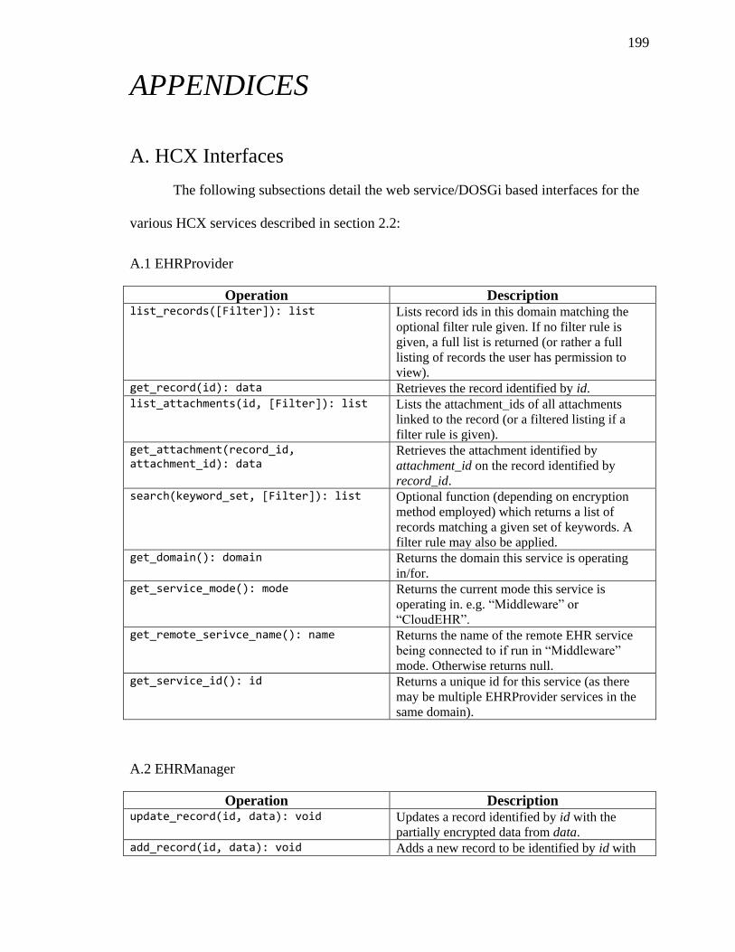
199
APPENDICES
A. HCX Interfaces
The following subsections detail the web service/DOSGi based interfaces for the
various HCX services described in section 2.2:
A.1 EHRProvider
Operation Description list_records([Filter]): list Lists record ids in this domain matching the
optional filter rule given. If no filter rule is
given, a full list is returned (or rather a full
listing of records the user has permission to
view). get_record(id): data Retrieves the record identified by id. list_attachments(id, [Filter]): list Lists the attachment_ids of all attachments
linked to the record (or a filtered listing if a
filter rule is given). get_attachment(record_id, attachment_id): data
Retrieves the attachment identified by
attachment_id on the record identified by
record_id. search(keyword_set, [Filter]): list Optional function (depending on encryption
method employed) which returns a list of
records matching a given set of keywords. A
filter rule may also be applied. get_domain(): domain Returns the domain this service is operating
in/for. get_service_mode(): mode Returns the current mode this service is
operating in. e.g. “Middleware” or
“CloudEHR”. get_remote_serivce_name(): name Returns the name of the remote EHR service
being connected to if run in “Middleware”
mode. Otherwise returns null. get_service_id(): id Returns a unique id for this service (as there
may be multiple EHRProvider services in the
same domain).
A.2 EHRManager
Operation Description update_record(id, data): void Updates a record identified by id with the
partially encrypted data from data. add_record(id, data): void Adds a new record to be identified by id with
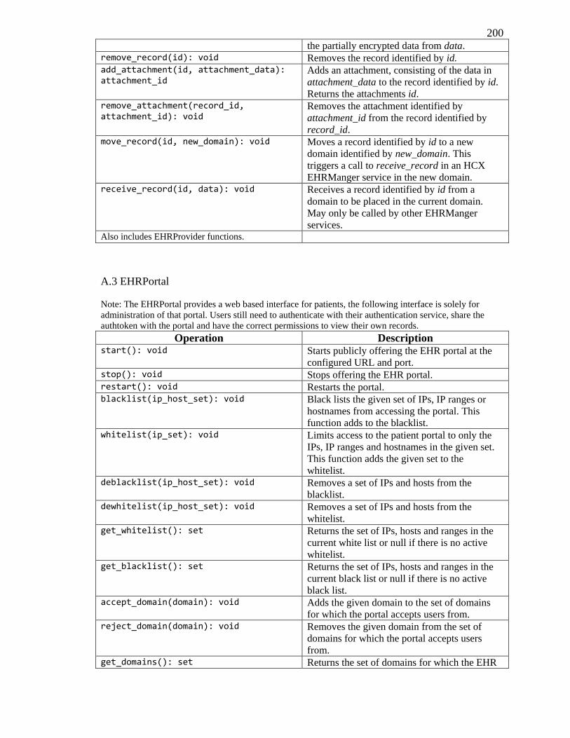
200 the partially encrypted data from data.
remove_record(id): void Removes the record identified by id. add_attachment(id, attachment_data): attachment_id
Adds an attachment, consisting of the data in
attachment_data to the record identified by id.
Returns the attachments id. remove_attachment(record_id, attachment_id): void
Removes the attachment identified by
attachment_id from the record identified by
record_id. move_record(id, new_domain): void Moves a record identified by id to a new
domain identified by new_domain. This
triggers a call to receive_record in an HCX
EHRManger service in the new domain. receive_record(id, data): void Receives a record identified by id from a
domain to be placed in the current domain.
May only be called by other EHRManger
services. Also includes EHRProvider functions.
A.3 EHRPortal
Note: The EHRPortal provides a web based interface for patients, the following interface is solely for
administration of that portal. Users still need to authenticate with their authentication service, share the
authtoken with the portal and have the correct permissions to view their own records.
Operation Description start(): void Starts publicly offering the EHR portal at the
configured URL and port. stop(): void Stops offering the EHR portal. restart(): void Restarts the portal. blacklist(ip_host_set): void Black lists the given set of IPs, IP ranges or
hostnames from accessing the portal. This
function adds to the blacklist. whitelist(ip_set): void Limits access to the patient portal to only the
IPs, IP ranges and hostnames in the given set.
This function adds the given set to the
whitelist. deblacklist(ip_host_set): void Removes a set of IPs and hosts from the
blacklist. dewhitelist(ip_host_set): void Removes a set of IPs and hosts from the
whitelist. get_whitelist(): set Returns the set of IPs, hosts and ranges in the
current white list or null if there is no active
whitelist. get_blacklist(): set Returns the set of IPs, hosts and ranges in the
current black list or null if there is no active
black list. accept_domain(domain): void Adds the given domain to the set of domains
for which the portal accepts users from. reject_domain(domain): void Removes the given domain from the set of
domains for which the portal accepts users
from. get_domains(): set Returns the set of domains for which the EHR
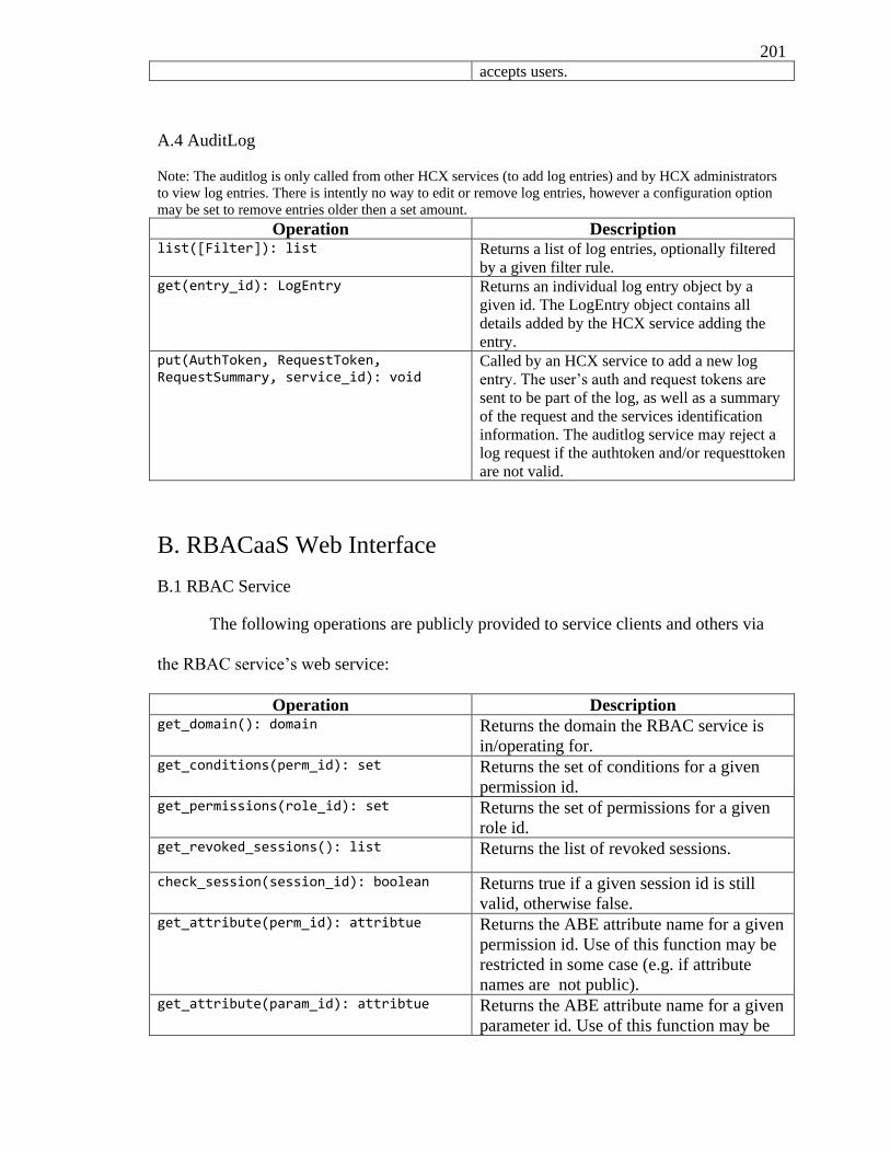
201 accepts users.
A.4 AuditLog
Note: The auditlog is only called from other HCX services (to add log entries) and by HCX administrators
to view log entries. There is intently no way to edit or remove log entries, however a configuration option
may be set to remove entries older then a set amount.
Operation Description list([Filter]): list Returns a list of log entries, optionally filtered
by a given filter rule. get(entry_id): LogEntry Returns an individual log entry object by a
given id. The LogEntry object contains all
details added by the HCX service adding the
entry. put(AuthToken, RequestToken, RequestSummary, service_id): void
Called by an HCX service to add a new log
entry. The user’s auth and request tokens are
sent to be part of the log, as well as a summary
of the request and the services identification
information. The auditlog service may reject a
log request if the authtoken and/or requesttoken
are not valid.
B. RBACaaS Web Interface
B.1 RBAC Service
The following operations are publicly provided to service clients and others via
the RBAC service’s web service:
Operation Description get_domain(): domain Returns the domain the RBAC service is
in/operating for. get_conditions(perm_id): set Returns the set of conditions for a given
permission id. get_permissions(role_id): set Returns the set of permissions for a given
role id. get_revoked_sessions(): list Returns the list of revoked sessions.
check_session(session_id): boolean Returns true if a given session id is still
valid, otherwise false. get_attribute(perm_id): attribtue Returns the ABE attribute name for a given
permission id. Use of this function may be
restricted in some case (e.g. if attribute
names are not public). get_attribute(param_id): attribtue Returns the ABE attribute name for a given
parameter id. Use of this function may be
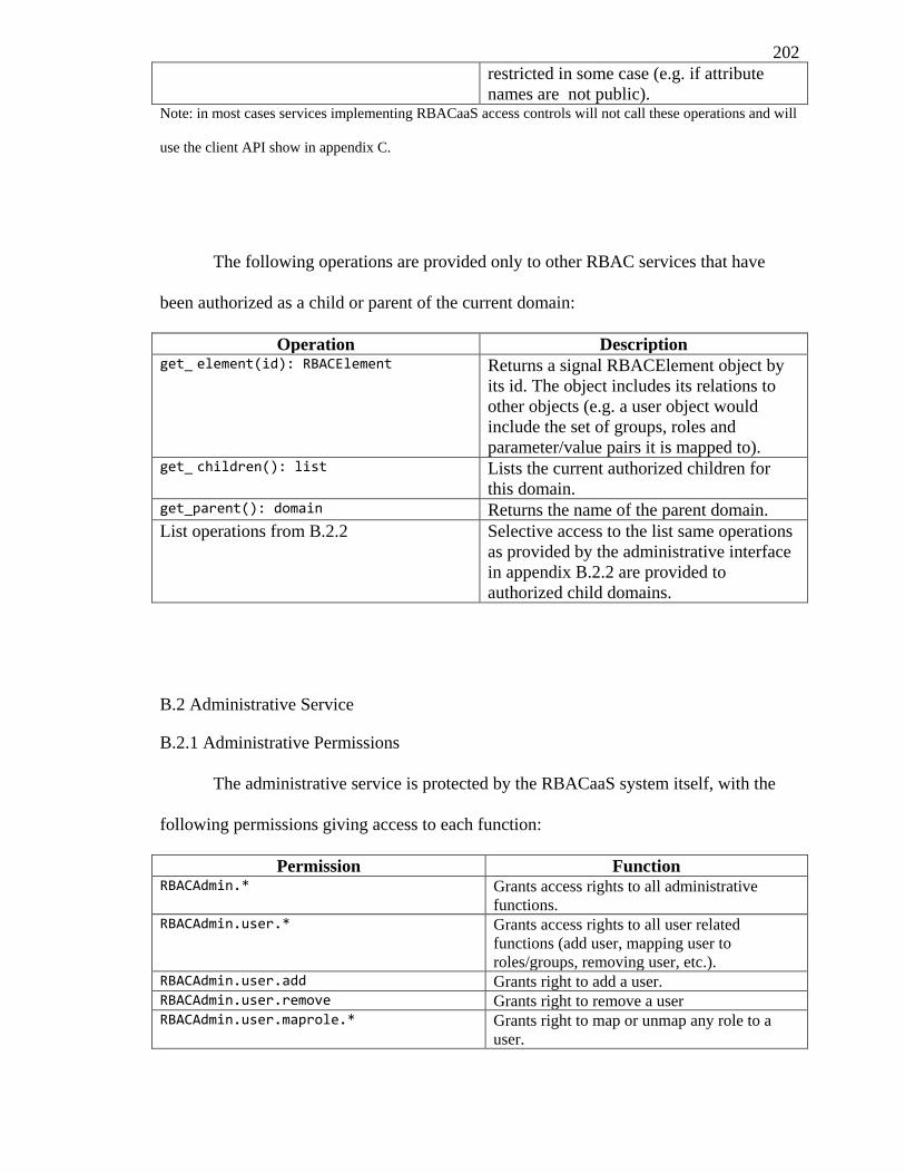
202
restricted in some case (e.g. if attribute
names are not public). Note: in most cases services implementing RBACaaS access controls will not call these operations and will
use the client API show in appendix C.
The following operations are provided only to other RBAC services that have
been authorized as a child or parent of the current domain:
Operation Description get_ element(id): RBACElement Returns a signal RBACElement object by
its id. The object includes its relations to
other objects (e.g. a user object would
include the set of groups, roles and
parameter/value pairs it is mapped to). get_ children(): list Lists the current authorized children for
this domain. get_parent(): domain Returns the name of the parent domain.
List operations from B.2.2 Selective access to the list same operations
as provided by the administrative interface
in appendix B.2.2 are provided to
authorized child domains.
B.2 Administrative Service
B.2.1 Administrative Permissions
The administrative service is protected by the RBACaaS system itself, with the
following permissions giving access to each function:
Permission Function RBACAdmin.* Grants access rights to all administrative
functions. RBACAdmin.user.* Grants access rights to all user related
functions (add user, mapping user to
roles/groups, removing user, etc.). RBACAdmin.user.add Grants right to add a user. RBACAdmin.user.remove Grants right to remove a user RBACAdmin.user.maprole.* Grants right to map or unmap any role to a
user.
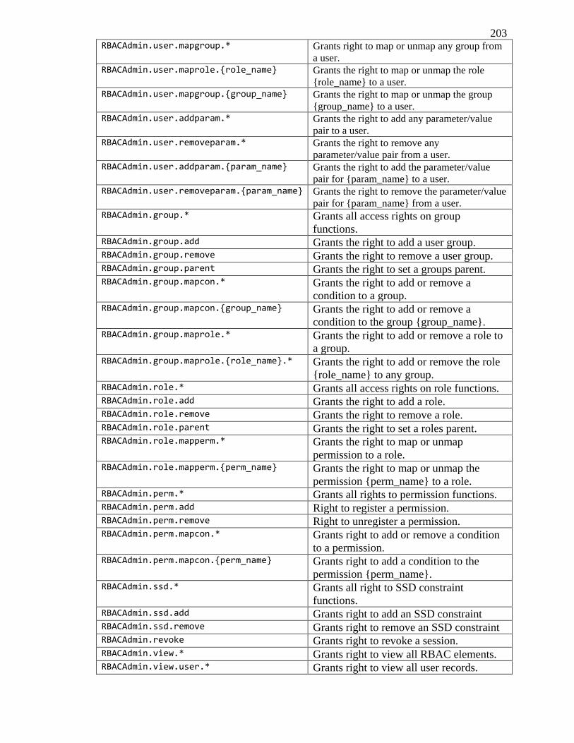
203 RBACAdmin.user.mapgroup.* Grants right to map or unmap any group from
a user. RBACAdmin.user.maprole.{role_name} Grants the right to map or unmap the role
{role_name} to a user. RBACAdmin.user.mapgroup.{group_name} Grants the right to map or unmap the group
{group_name} to a user. RBACAdmin.user.addparam.* Grants the right to add any parameter/value
pair to a user. RBACAdmin.user.removeparam.* Grants the right to remove any
parameter/value pair from a user. RBACAdmin.user.addparam.{param_name} Grants the right to add the parameter/value
pair for {param_name} to a user. RBACAdmin.user.removeparam.{param_name} Grants the right to remove the parameter/value
pair for {param_name} from a user. RBACAdmin.group.* Grants all access rights on group
functions. RBACAdmin.group.add Grants the right to add a user group. RBACAdmin.group.remove Grants the right to remove a user group. RBACAdmin.group.parent Grants the right to set a groups parent. RBACAdmin.group.mapcon.* Grants the right to add or remove a
condition to a group. RBACAdmin.group.mapcon.{group_name} Grants the right to add or remove a
condition to the group {group_name}. RBACAdmin.group.maprole.* Grants the right to add or remove a role to
a group. RBACAdmin.group.maprole.{role_name}.* Grants the right to add or remove the role
{role_name} to any group. RBACAdmin.role.* Grants all access rights on role functions. RBACAdmin.role.add Grants the right to add a role. RBACAdmin.role.remove Grants the right to remove a role. RBACAdmin.role.parent Grants the right to set a roles parent. RBACAdmin.role.mapperm.* Grants the right to map or unmap
permission to a role. RBACAdmin.role.mapperm.{perm_name} Grants the right to map or unmap the
permission {perm_name} to a role. RBACAdmin.perm.* Grants all rights to permission functions. RBACAdmin.perm.add Right to register a permission. RBACAdmin.perm.remove Right to unregister a permission. RBACAdmin.perm.mapcon.* Grants right to add or remove a condition
to a permission. RBACAdmin.perm.mapcon.{perm_name} Grants right to add a condition to the
permission {perm_name}. RBACAdmin.ssd.* Grants all right to SSD constraint
functions. RBACAdmin.ssd.add Grants right to add an SSD constraint RBACAdmin.ssd.remove Grants right to remove an SSD constraint RBACAdmin.revoke Grants right to revoke a session. RBACAdmin.view.* Grants right to view all RBAC elements. RBACAdmin.view.user.* Grants right to view all user records.
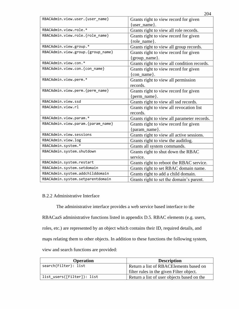
204 RBACAdmin.view.user.{user_name} Grants right to view record for given
{user_name}. RBACAdmin.view.role.* Grants right to view all role records. RBACAdmin.view.role.{role_name} Grants right to view record for given
{role_name}. RBACAdmin.view.group.* Grants right to view all group records. RBACAdmin.view.group.{group_name} Grants right to view record for given
{group_name}. RBACAdmin.view.con.* Grants right to view all condition records. RBACAdmin.view.con.{con_name} Grants right to view record for given
{con_name}. RBACAdmin.view.perm.* Grants right to view all permission
records. RBACAdmin.view.perm.{perm_name} Grants right to view record for given
{perm_name}. RBACAdmin.view.ssd Grants right to view all ssd records. RBACAdmin.view.rl Grants right to view all revocation list
records. RBACAdmin.view.param.* Grants right to view all parameter records. RBACAdmin.view.param.{param_name} Grants right to view record for given
{param_name}. RBACAdmin.view.sessions Grants right to view all active sessions. RBACAdmin.view.log Grants right to view the auditlog. RBACAdmin.system.* Grants all system commands. RBACAdmin.system.shutdown Grants right to shut down the RBAC
service. RBACAdmin.system.restart Grants right to reboot the RBAC service. RBACAdmin.system.setdomain Grants right to set RBAC domain name. RBACAdmin.system.addchilddomain Grants right to add a child domain. RBACAdmin.system.setparentdomain Grants right to set the domain’s parent.
B.2.2 Administrative Interface
The administrative interface provides a web service based interface to the
RBACaaS administrative functions listed in appendix D.5. RBAC elements (e.g. users,
roles, etc.) are represented by an object which contains their ID, required details, and
maps relating them to other objects. In addition to these functions the following system,
view and search functions are provided:
Operation Description search(Filter): list Return a list of RBACElements based on
filter rules in the given Filter object. list_users([Filter]): list Return a list of user objects based on the
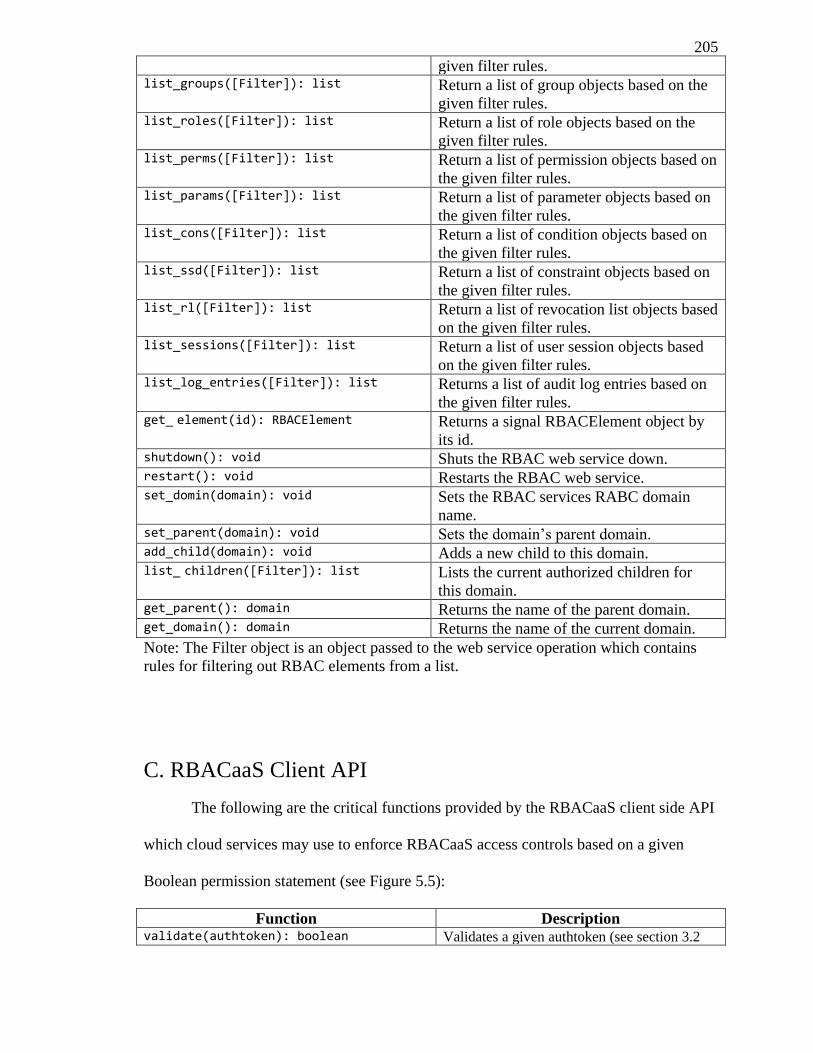
205
given filter rules. list_groups([Filter]): list Return a list of group objects based on the
given filter rules. list_roles([Filter]): list Return a list of role objects based on the
given filter rules. list_perms([Filter]): list Return a list of permission objects based on
the given filter rules. list_params([Filter]): list Return a list of parameter objects based on
the given filter rules. list_cons([Filter]): list Return a list of condition objects based on
the given filter rules. list_ssd([Filter]): list Return a list of constraint objects based on
the given filter rules. list_rl([Filter]): list Return a list of revocation list objects based
on the given filter rules. list_sessions([Filter]): list Return a list of user session objects based
on the given filter rules. list_log_entries([Filter]): list Returns a list of audit log entries based on
the given filter rules. get_ element(id): RBACElement Returns a signal RBACElement object by
its id. shutdown(): void Shuts the RBAC web service down. restart(): void Restarts the RBAC web service. set_domin(domain): void Sets the RBAC services RABC domain
name. set_parent(domain): void Sets the domain’s parent domain. add_child(domain): void Adds a new child to this domain. list_ children([Filter]): list Lists the current authorized children for
this domain. get_parent(): domain Returns the name of the parent domain. get_domain(): domain Returns the name of the current domain.
Note: The Filter object is an object passed to the web service operation which contains
rules for filtering out RBAC elements from a list.
C. RBACaaS Client API
The following are the critical functions provided by the RBACaaS client side API
which cloud services may use to enforce RBACaaS access controls based on a given
Boolean permission statement (see Figure 5.5):
Function Description validate(authtoken): boolean Validates a given authtoken (see section 3.2
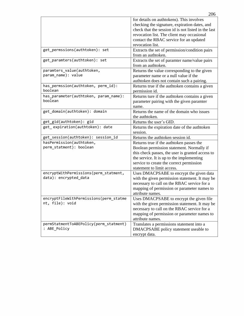
206 for details on authtokens). This involves
checking the signature, expiration dates, and
check that the session id is not listed in the last
revocation list. The client may occasional
contact the RBAC service for an updated
revocation list. get_permssions(authtoken): set Extracts the set of permission/condition pairs
from an authtoken. get_paramters(authtoken): set Extracts the set of paramter name/value pairs
from an authtoken. paramters_value(authtoken, param_name): value
Returns the value corresponding to the given
parameter name or a null value if the
authtoken does not contain such a pairing. has_permssion(authtoken, perm_id): boolean
Returns true if the authtoken contains a given
permission id. has_parameter(authtoken, param_name): boolean
Returns ture if the authtoken contains a given
parameter pairing with the given paramter
name. get_domain(authtoken): domain Returns the name of the domain who issues
the authtoken. get_gid(authtoken): gid Returns the user’s GID. get_ expiration(authtoken): date Returns the expiration date of the authtoken
session. get_session(authtoken): session_id Returns the authtoken session id. hasPermission(authtoken, perm_statment): boolean
Returns true if the authtoken passes the
Boolean permission statement. Normally if
this check passes, the user is granted access to
the service. It is up to the implementing
service to create the correct permission
statement to limit access. encryptWithPermissions(perm_statment, data): encrypted_data
Uses DMACPSABE to encrypt the given data
with the given permission statement. It may be
necessary to call on the RBAC service for a
mapping of permission or parameter names to
attribute names. encryptFileWithPermissions(perm_statment, file): void
Uses DMACPSABE to encrypt the given file
with the given permission statement. It may be
necessary to call on the RBAC service for a
mapping of permission or parameter names to
attribute names. permStatmentToABEPolicy(perm_statment): ABE_Policy
Translates a permissions statement into a
DMACPSABE policy statement useable to
encrypt data.
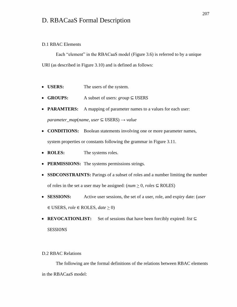
207
D. RBACaaS Formal Description
D.1 RBAC Elements
Each “element” in the RBACaaS model (Figure 3.6) is referred to by a unique
URI (as described in Figure 3.10) and is defined as follows:
USERS: The users of the system.
GROUPS: A subset of users: group ⊆ USERS
PARAMTERS: A mapping of parameter names to a values for each user:
parameter_map(name, user ⊆ USERS) → value
CONDITIONS: Boolean statements involving one or more parameter names,
system properties or constants following the grammar in Figure 3.11.
ROLES: The systems roles.
PERMISSIONS: The systems permissions strings.
SSDCONSTRAINTS: Parings of a subset of roles and a number limiting the number
of roles in the set a user may be assigned: (num > 0, roles ⊆ ROLES)
SESSIONS: Active user sessions, the set of a user, role, and expiry date: (user
USERS, role ROLES, date > 0)
REVOCATIONLIST: Set of sessions that have been forcibly expired: list ⊆
SESSIONS
D.2 RBAC Relations
The following are the formal definitions of the relations between RBAC elements
in the RBACaaS model:
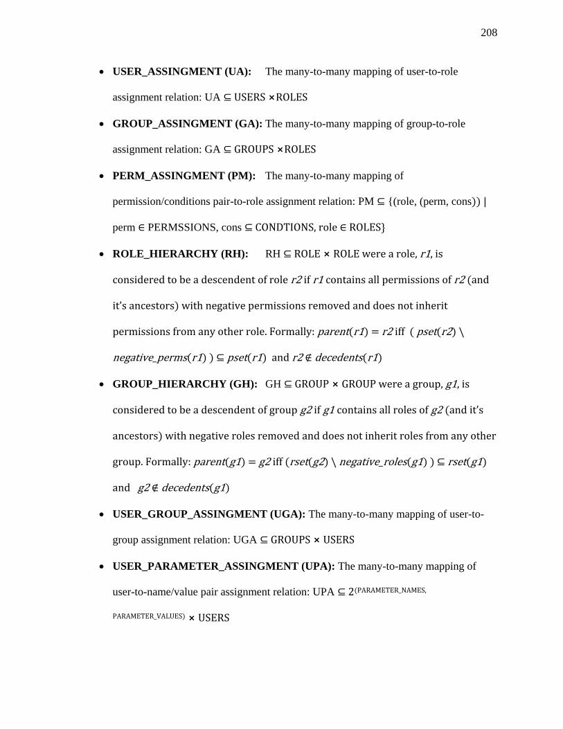
208
USER_ASSINGMENT (UA): The many-to-many mapping of user-to-role
assignment relation: UA ⊆ USERS ⨯ROLES
GROUP_ASSINGMENT (GA): The many-to-many mapping of group-to-role
assignment relation: GA ⊆ ROU S ⨯ROLES
PERM_ASSINGMENT (PM): The many-to-many mapping of
permission/conditions pair-to-role assignment relation: PM ⊆ {(role, (perm, cons)) |
perm PERMSSIONS, cons ⊆ CO D O S ROLES}
ROLE_HIERARCHY (RH): RH ⊆ ROLE ⨯ ROLE r1, is
considered to be a descendent of role r2 if r1 contains all permissions of r2 (and
’ )
permissions from any other role. Formally: parent(r1) = r2 iff ( pset(r2) \
negative_perms(r1) ) ⊆ pset(r1) and r2 ∉ decedents(r1)
GROUP_HIERARCHY (GH): GH ⊆ ROU ⨯ ROU g1, is
considered to be a descendent of group g2 if g1 contains all roles of g2 ( ’
ancestors) with negative roles removed and does not inherit roles from any other
group. Formally: parent(g1) = g2 iff (rset(g2) \ negative_roles(g1) ) ⊆ rset(g1)
and g2 ∉ decedents(g1)
USER_GROUP_ASSINGMENT (UGA): The many-to-many mapping of user-to-
group assignment relation: UGA ⊆ ROU S ⨯ USERS
USER_PARAMETER_ASSINGMENT (UPA): The many-to-many mapping of
user-to-name/value pair assignment relation: UPA ⊆ (PARAMETER_NAMES,
PARAMETER_VALUES) ⨯ USERS
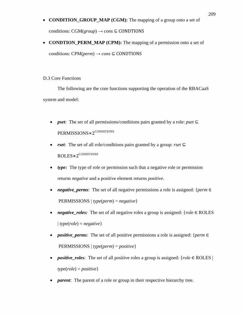
209
CONDITION_GROUP_MAP (CGM): The mapping of a group onto a set of
conditions: CGM(group) → cons ⊆ CO D O S
CONDTION_PERM_MAP (CPM): The mapping of a permission onto a set of
conditions: CPM(perm) → cons ⊆ CO D O S
D.3 Core Functions
The following are the core functions supporting the operation of the RBACaaS
system and model:
pset: The set of all permissions/conditions pairs granted by a role: pset ⊆
PERMISSIONS⨯ CONDITIONS
rset: The set of all role/conditions pairs granted by a group: rset ⊆
ROLES⨯ CONDITIONS
type: The type of role or permission such that a negative role or permission
returns negative and a positive element returns positive.
negative_perms: The set of all negative permissions a role is assigned: {perm
PERMISSIONS | type(perm) = negative}
negative_roles: The set of all negative roles a group is assigned: {role ROLES
| type(role) = negative}
positive_perms: The set of all positive permissions a role is assigned: {perm
PERMISSIONS | type(perm) = positive}
positive_roles: The set of all positive roles a group is assigned: {role ROLES |
type(role) = positive}
parent: The parent of a role or group in their respective hierarchy tree.
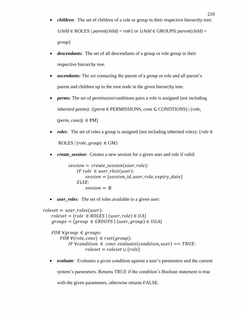
210
children: The set of children of a role or group in their respective hierarchy tree:
{child ROLES | parent(child) = role} or {child GROUPS| parent(child) =
group}
descendants: The set of all descendants of a group or role group in their
respective hierarchy tree.
ascendants: The set contacting the parent of a group or role and all parent’s
parent and children up to the root node in the given hierarchy tree.
perms: The set of permission/conditions pairs a role is assigned (not including
inherited perms): {(perm PERMISSIONS, cons ⊆ CONDTIONS) | (role,
(perm, cons)) PM}
roles: The set of roles a group is assigned (not including inherited roles): {role
ROLES | (role, group) GM}
create_session: Creates a new session for a given user and role if valid:
( ) ( )
user_roles: The set of roles available to a given user:
( ) | ( ) | ( )
( ) ( )
( )
evaluate: Evaluates a given condition against a user’s parameters and the current
system’s parameters. Returns TRUE if the condition’s Boolean statement is true
with the given parameters, otherwise returns FALSE.
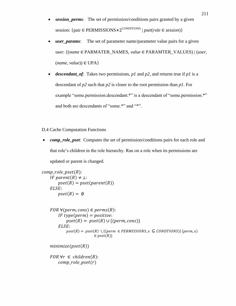
211
session_perms: The set of permission/conditions pairs granted by a given
session: {pair PERMISSIONS⨯ CONDITIONS | pset(role session)}
user_params: The set of parameter name/parameter value pairs for a given
user: {(name PARMATER_NAMES, value PARAMTER_VALUES) | (user,
(name, value)) UPA}
descendant_of: Takes two permissions, p1 and p2, and returns true if p1 is a
descendant of p2 such that p2 is closer to the root permission than p1. For
example “some.permission.descendant.*” is a descendant of “some.permission.*”
and both are descendants of “some.*” and “*”.
D.4 Cache Computation Functions
comp_role_pset: Computes the set of permission/conditions pairs for each role and
that role’s children in the role hierarchy. Ran on a role when its permissions are
updated or parent is changed.
( ) ( )
( ) ( ( ))
( )
( ) ( ) ( )
( ) ( ) ( )
( ) ( ) ( ⊆ )| ( ) ( )
( ( ))
( ) ( )
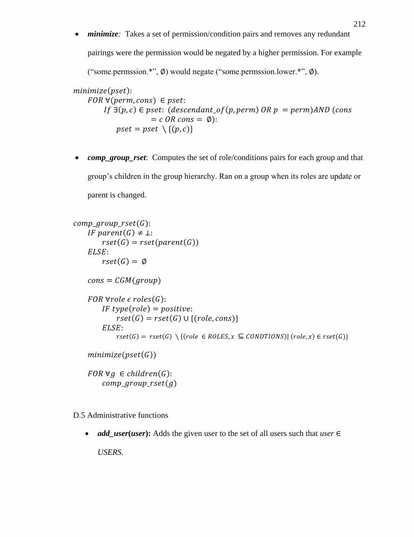
212
minimize: Takes a set of permission/condition pairs and removes any redundant
pairings were the permission would be negated by a higher permission. For example
(“some.permssion.*”, ) would negate (“some.permssion.lower.*”, ).
( ) ( )
( ) ( ( ) ) ( )
( )
comp_group_rset: Computes the set of role/conditions pairs for each group and that
group’s children in the group hierarchy. Ran on a group when its roles are update or
parent is changed.
( ) ( )
( ) ( ( ))
( )
( )
( ) ( )
( ) ( ) ( )
( ) ( ) ( ⊆ )| ( ) ( )
( ( ))
( ) ( )
D.5 Administrative functions
add_user(user): Adds the given user to the set of all users such that user
USERS.
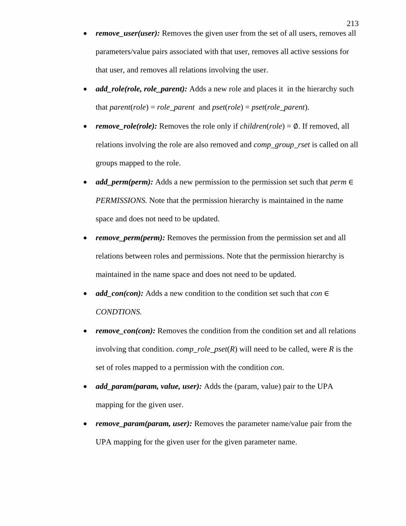
213
remove_user(user): Removes the given user from the set of all users, removes all
parameters/value pairs associated with that user, removes all active sessions for
that user, and removes all relations involving the user.
add_role(role, role_parent): Adds a new role and places it in the hierarchy such
that parent(role) = role_parent and pset(role) = pset(role_parent).
remove_role(role): Removes the role only if children(role) = . If removed, all
relations involving the role are also removed and comp_group_rset is called on all
groups mapped to the role.
add_perm(perm): Adds a new permission to the permission set such that perm
PERMISSIONS. Note that the permission hierarchy is maintained in the name
space and does not need to be updated.
remove_perm(perm): Removes the permission from the permission set and all
relations between roles and permissions. Note that the permission hierarchy is
maintained in the name space and does not need to be updated.
add_con(con): Adds a new condition to the condition set such that con
CONDTIONS.
remove_con(con): Removes the condition from the condition set and all relations
involving that condition. comp_role_pset(R) will need to be called, were R is the
set of roles mapped to a permission with the condition con.
add_param(param, value, user): Adds the (param, value) pair to the UPA
mapping for the given user.
remove_param(param, user): Removes the parameter name/value pair from the
UPA mapping for the given user for the given parameter name.
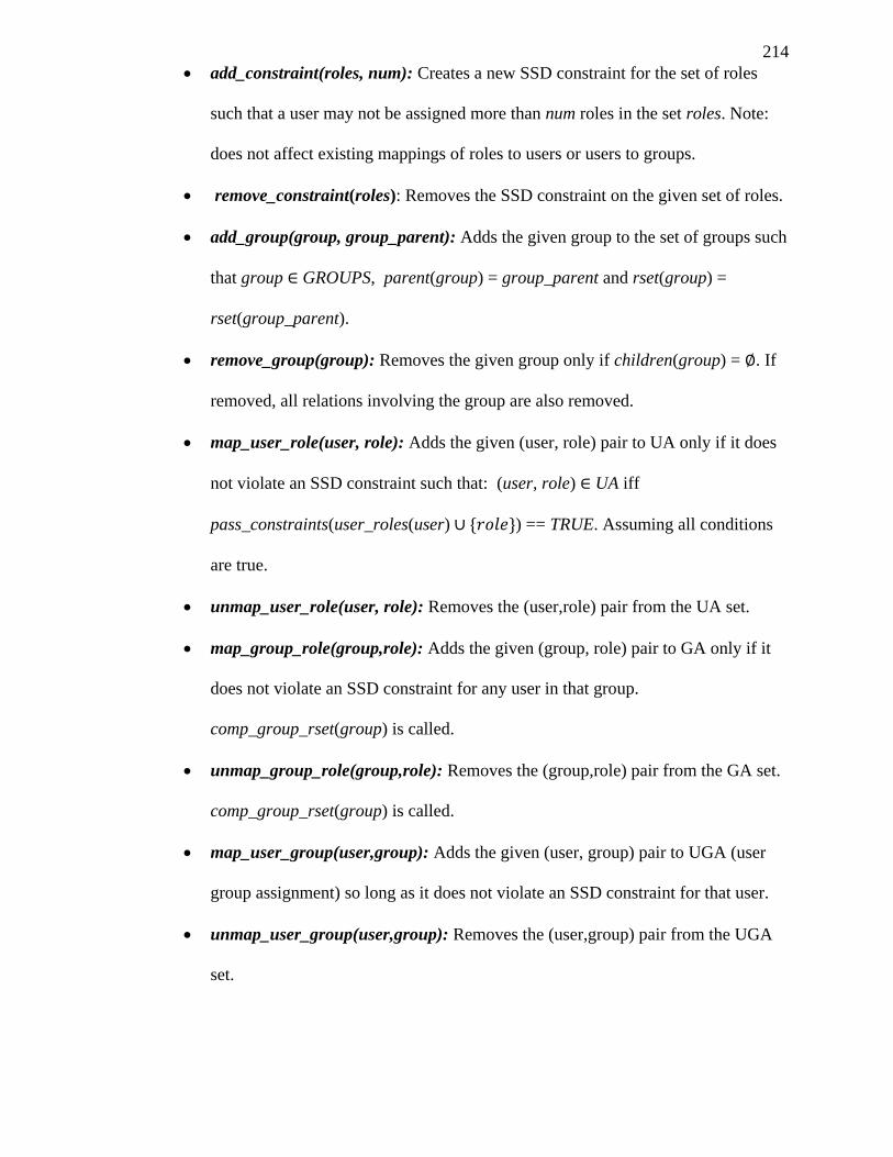
214
add_constraint(roles, num): Creates a new SSD constraint for the set of roles
such that a user may not be assigned more than num roles in the set roles. Note:
does not affect existing mappings of roles to users or users to groups.
remove_constraint(roles): Removes the SSD constraint on the given set of roles.
add_group(group, group_parent): Adds the given group to the set of groups such
that group GROUPS, parent(group) = group_parent and rset(group) =
rset(group_parent).
remove_group(group): Removes the given group only if children(group) = . If
removed, all relations involving the group are also removed.
map_user_role(user, role): Adds the given (user, role) pair to UA only if it does
not violate an SSD constraint such that: (user, role) UA iff
pass_constraints(user_roles(user) ) == TRUE. Assuming all conditions
are true.
unmap_user_role(user, role): Removes the (user,role) pair from the UA set.
map_group_role(group,role): Adds the given (group, role) pair to GA only if it
does not violate an SSD constraint for any user in that group.
comp_group_rset(group) is called.
unmap_group_role(group,role): Removes the (group,role) pair from the GA set.
comp_group_rset(group) is called.
map_user_group(user,group): Adds the given (user, group) pair to UGA (user
group assignment) so long as it does not violate an SSD constraint for that user.
unmap_user_group(user,group): Removes the (user,group) pair from the UGA
set.
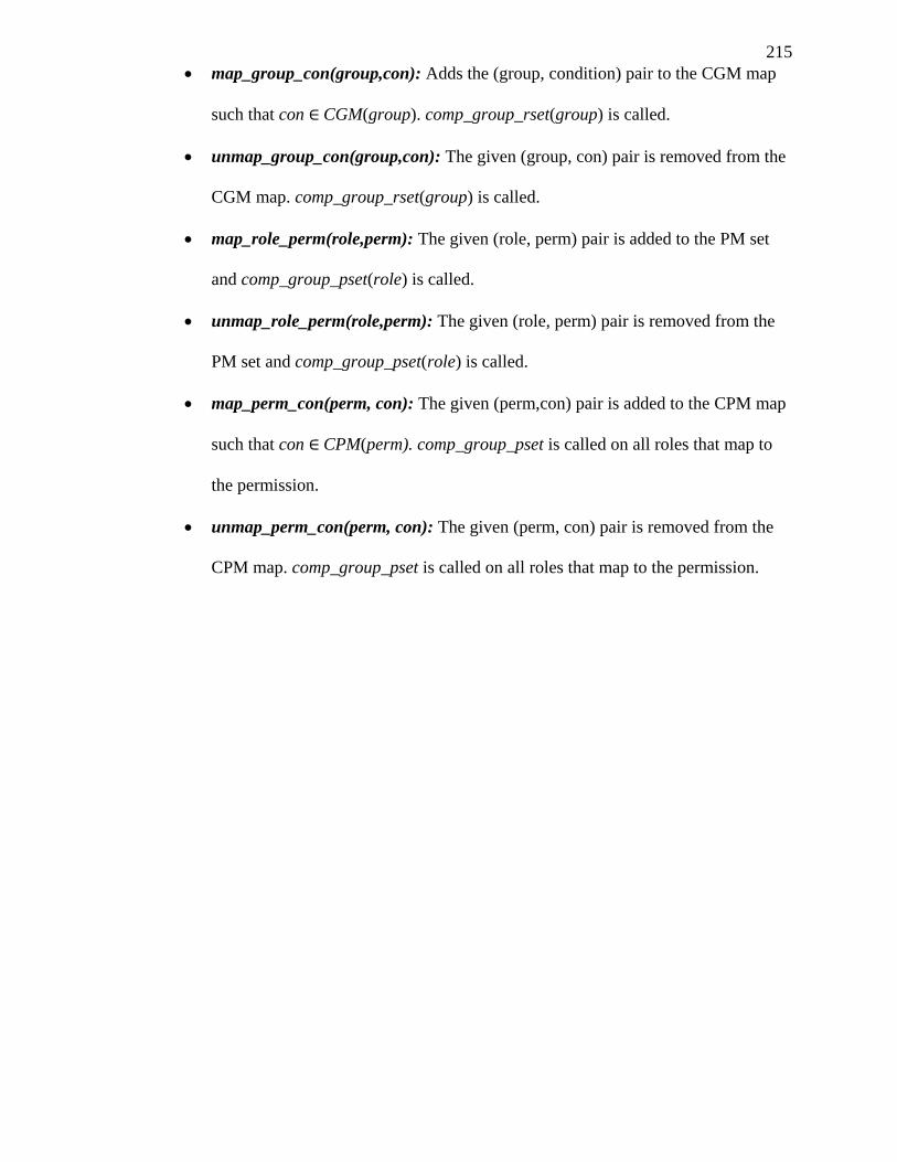
215
map_group_con(group,con): Adds the (group, condition) pair to the CGM map
such that con CGM(group). comp_group_rset(group) is called.
unmap_group_con(group,con): The given (group, con) pair is removed from the
CGM map. comp_group_rset(group) is called.
map_role_perm(role,perm): The given (role, perm) pair is added to the PM set
and comp_group_pset(role) is called.
unmap_role_perm(role,perm): The given (role, perm) pair is removed from the
PM set and comp_group_pset(role) is called.
map_perm_con(perm, con): The given (perm,con) pair is added to the CPM map
such that con CPM(perm). comp_group_pset is called on all roles that map to
the permission.
unmap_perm_con(perm, con): The given (perm, con) pair is removed from the
CPM map. comp_group_pset is called on all roles that map to the permission.

216
217
REFERENCES
Adaikkalavan, R., & Chakravarthy, S. (2006). Discovery-based role activations in role-
based access control. Performance, Computing, and Communications Conference, 2006.
IPCCC 2006. 25th IEEE International (p. pp. 8). Phoenix: IEEE.
Akinyele, J. A., Lehmann, C. U., Green, M. D., Pagano, M. W., Peterson, Z. N., &
Rubin, A. D. (2010). Self-Protecting Electronic Medical Records Using Attribute-Based
Encryption. Cryptology ePrint Archive, Available from http://eprint.iacr.org.
Armbrust, M., Fox, A., Griffith, R., Joseph, A. D., Katz, R., Konwinski, A., et al. (2009).
Above the Clouds: A Berkeley View of Cloud. Berkeley: UC Berkeley Reliable Adaptive
Distributed Systems Laboratory.
ASTM International. (2005). ASTM Standard E2369 - 05e2 Standard Specification for
Continuity of Care Record (CCR). West Conshohocken, PA.
ASTM Subcommittee: E31.25. (2005). ASTM E2369 - 05e1 Standard Specification for
Continuity of Care Record (CCR). In ASTM, ASTM Book of Standards vol. 14.01.
Balboni, P. (2010). Data Protection and Data Security Issues Related to Cloud
Computing in the EU. Tilburg: Tilburg University Legal Studies Working Paper Series.
Ballard, L., Green, M., Medeiros, B. d., & Monrose, F. (2005). Correlation-Resistant
Storage via Keyword-Searchable Encryption. Cryptology ePrint Archive.
Belokosztolszki, A., & Eyers, D. (2002). Shielding the OASIS RBAC infrastructure from
cyber-terrorism. Proceedings of the IFIP WG 11.3 Conference.
Best, R. (1980). Preventing Software Piracy with Crypto-Microprocessors. Proceedings
of IEEE Spring COMPCON 80, pp. 466-469.
Bethencourt, J., Sahai, A., & Waters, B. (2007). Ciphertext-Policy Attribute-Based
Encryption. 2007 IEEE Symposium on Security and Privacy (SP '07) (pp. p.321-334).
Oakland: IEEE.
Bethencourt, J., Sahai, A., Waters, B., & B. (2006, December 1). Retrieved November 8,
2011, from Advanced Crypto Software Collection: Ciphertext-Policy Attribute-Based
Encryption: http://acsc.cs.utexas.edu/cpabe/
Blake, I. F., Murty, V. K., & Xu, G. (2006). Refinements of Miller's algorithm for
computing the Weil/Tate pairing. Journal of Algorithms, v. 58 i. 2 p. 134 - 149.
Boer, B. d. (1996). Diffie-Hellman is as strong as discrete log for certain primes.
Advances in Cryptology.
Boneh, D., & Franklin, M. (2001). Identity-Based Encryption from the Weil Pairing.
Advances in Cryptology.
218
Boneh, D., Boyen, X., & Goh, E.-J. (2005). Hierarchical identity based encryption with
constant size ciphertext. EUROCRYPT, volume 3494 of Lecture Notes in Computer
Science, p. 440–456.
Buyya, R., Yeo, C. S., & Venugopal, S. (2008). Market-Oriented Cloud Computing:
Market-Oriented Cloud Computing:Vision, Hype, and Reality for Delivering IT Services
as Computing Utilities. Proceedings of the 10th IEEE International Conference on High
Performance Computing and Communications. Los Alamitos.
Chang, Y.-C., & Mitzenmacher, M. (2005). Privacy Preserving Keyword Searches on
Remote Encrypted Data. Applied Cryptography and Network Security, vol. 3531 pp. 391.
Chow, R., Golle, P., Jakobsson, M., Masuoka, R., Molina, J., Shi, E., et al. (2009).
Controlling Data in the Cloud: Outsourcing Computation without Outsourcing Control.
Proceedings of the 2009 ACM workshop on Cloud computing security (pp. 85-90).
Chicago: ACM.
Cocks, C. (2001). An Identity Based Encryption Scheme Based on Quadratic Residues.
In Proceedings of the 8th IMA International Conference on Cryptography and Coding,
(pp. p. 360-363). London.
DOLIN, R. H., ALSCHULER, L., BOYER, S., & BEEBE, C. (2006). HL7 Clinical
Document Architecture, Release 2. Journal of the American Medical Informatics
Association, pp. 30.
Ferraiolo, D. F., & Kuhn, D. R. (1992). Role-Based Access Controls. 15th National
Computer Security Conference, (pp. 554 - 563). Baltimore.
Ferraiolo, D., Sandhu, R., Gavrila, S., Kuhn, D., & Chandramouli, R. (2001). Proposed
NIST standard for role-based access control. ACM Transactions on Information and
System Security (TISSEC), 224–274.
Freudenthal, E., Pesin, T., Port, L., Keenan, E., & Karamcheti, V. (2002). dRBAC:
distributed role-based access control for dynamic coalition environments. Distributed
Computing Systems, 2002. Proceedings. 22nd International Conference on (p. pp. 411).
Vienna, Austria: IEEE.
Fujisaki, E., & Okamoto, T. (1999). Secure integration of asymmetric and symmetric
encryption schemes. CRYPTO '99 Proceedings of the 19th Annual International
Cryptology, (pp. p. 537-554). California.
Galbraith, S. D., Harrison, K., & Soldera, D. (2002). Implementing the Tate Pairing.
Algorithmic Number Theory - Lecture Notes in Computer Science, v. 2369 p. 69 - 86.
Geelan, J. (2008). Twenty-One Experts Define Cloud Computing. Retrieved Febuary 5,
2010, from Cloud Computing Journal: http://cloudcomputing.sys-
con.com/node/612375/print
Gellman, R. (2009). Privacy in the Clouds: Risks to Privacy and Confidentiality from
Cloud Computing. World Privacy Forum.
219
Goh, C., & Baldwin, A. (1998). Towards a more complete model of role. In Third ACM
Workshop on Role-Based Access Control, (p. pp. 55). Fairfax, Virginia.
Goyal, V., Pandey, O., Sahai, A., & Waters, B. (2006). Attribute-based encryption for
fine-grained access control of encrypted data. Proceedings of the 13th ACM conference
on Computer and communications security (CCS '06) (p. p. 89). Alexandria: ACM Press.
Guo, Q., Vaidya, J., & Atluri, V. (2008). The Role Hierarchy Mining Problem: Discovery
of Optimal Role Hierarchies . Computer Security Applications Conference, 2008. (p. pp.
237). Anaheim: ACSAC.
Halderman, J. A., Schoen, S. D., Heninger, N., Clarkson, W., Paul, W., Calandrino, J. A.,
et al. (2009). Lest we remember: cold-boot attacks on encryption keys. Communications
of the ACM - Security in the Browser, vol. 52, i. 5.
Health Level Seven International. (2007). Continuity of Care Document (CCD) Release
1.
InterNational Committee for Information Technology Standards. (2004). RBAC
Standard, ANSI INCITS 359-2004.
Itani, W., Kayssi, A., & Chehab, A. (2005). PATRIOT – a Policy-Based, Multi-level
Security Protocol for Safekeeping Audit Logs on Wireless Devices. Proc. of IEEE
SecureComm’05. Athens, Greece: IEEE.
Itani, W., Kayssi, A., & Chehab, A. (2009). Privacy as a Service: Privacy-Aware Data
Storage. Eighth IEEE International Conference on Dependable, Autonomic and Secure
Computing (pp. 711 - 716). Chengdu: IEEE.
Kuhlmann, M., Shohat, D., & Schimpf, G. (2003). Role mining - revealing business roles
for security administration using data mining technology. SACMAT '03 Proceedings of
the eighth ACM symposium on Access control models and technologies . New York:
ACM.
Li, J., Au, M. H., Susilo, W., Xie, D., & Ren, K. (2010). Attribute-based signature and its
applications. ASIACCS '10 Proceedings of the 5th ACM Symposium on Information,
Computer and Communications Security (p. pp. 60). New York: ACM.
Li, J., Wang, Q., Wang, C., Cao, N., Ren, K., & Lou, W. (2010). Fuzzy Keyword Search
over Encrypted Data in Cloud Computing. INFOCOM, 2010 Proceedings IEEE (p. pp.
1). San Diego, CA: IEEE.
Li, N., Byun, J.-W., & Bertino, E. (2007). A Critique of the ANSI Standard on Role-
Based Access Control. IEEE Security & Privacy Magazine, vol. 6, pg 41-49.
Lynn, B. (2011). Retrieved November 8, 2011, from PBC Library - Pairing-Based
Cryptography: http://crypto.stanford.edu/pbc/
Lynn, B. (n.d.). The Pairing-Based Cryptography Library. Retrieved November 8, 2011,
from PBC Library: http://crypto.stanford.edu/pbc/
220
Maurer, U., & Wolf, S. (1999). The relationship between breaking the Diffie-Hellman
protocol and computing discrete logarithms. SIAM Journal on Computing, v. 28 p. 1689-
1731.
Miller, V. (2004). The Weil Pairing, and Its Efficient Calculation. Journal of Cryptology,
v. 17 i. 4 p. 235-261.
Miller, V. S. (1986). Short programs for functions on curves. unpublished manuscript.
Nyanchama, M., & Osborn, S. (1999). The Role Graph Model and Conflict of Interest.
ACM Transactions on Information and System Security (TISSEC) - Special issue on role-
based access control, vol. 2, i. 1.
Osborn, S., Sandhu, R., & Munawer, Q. (2000). Configuring role-based access control to
enforce mandatory and discretionary access control policies. ACM Transactions on
Information and System Security, vol. 3, pp. 85.
Park, J., & Sandhu, R. (2004). The UCONABC usage control model. ACM Transactions
on Information and System Security (TISSEC), vol. 7, i. 1, pp. 128.
Pearson, S., Shen, Y., & Mowbray, M. (2009). A Privacy Manager for Cloud Computing.
Lecture Notes in Computer Science, vol. 5931, pp. 90-106.
Sahai, A., & Waters, B. (2005). Fuzzy Identity-Based Encryption. Advances in
Cryptology – EUROCRYPT 2005, (pp. vol. 3494, pp. 457-473). Aarhus.
Saltzer, J., & Schroeder, M. (1975). The protection of information in computer systems.
Proceedings of the IEEE, vo. 63 pg. 1278-1308.
Samyde, D., Skorobogatov, S., Anderson, R., & Quisquater, J.-J. (2003). On a New Way
to Read Data from Memory. Security in Storage Workshop, 2002. Proceedings. First
International IEEE (pp. pp. 65 - 69). Greenbelt, Maryland: IEEE.
Sandhu, R. S., Coyne, E. J., Feinstein, H. L., & Youman, C. E. (1996). Role-Based
Access Control Models. IEEE Computer, 38 - 47.
Sandhu, R., Bhamidipati, V., & Munawer, Q. (1999). The ARBAC97 model for role-
based administration of roles. ACM Transactions on Information and System Security
(TISSEC) - Special issue on role-based access control, vol. 2, i. 1, pp. 3.
Santos, N., Gummadi, K. P., & Rodrigues, R. (2009). Towards Trusted Cloud
Computing. Proceedings of the 2009 conference on Hot topics in cloud computing . San
Diego.
Schneier, B., & Kelsey, J. (1999). Secure Audit Logs to Support Computer Forensics.
ACM Transactions on Information and System Security 2, pp. 159-196.
Shaniqng, G., & Yingpei, Z. (2008). Attribute-based Signature Scheme. Information
Security and Assurance, 2008. ISA 2008. International Conference on (p. pp. 509).
Busan: ISA.
221
Sweeney, L. (2002). k-anonymity: A model for protecting privacy. International Journal
of Uncertainty, Fuzziness and Knowledge-Based Systems, pp. 557-570.
Tygar, J. D., & Yee, B. (1994). Dyad: A system for using physically secure coprocessors.
In Proc. of IP Workshop.
Urowitz, S., Wiljer, D., Apatu, E., Eysenbach, G., DeLenardo, C., Harth, T., et al. (2008).
Is Canada ready for patient accessible electronic health records? A national scan. BMC
Medical Informatics and Decision Making, p. 33.
Vaidya, J., Atluri, V., & Guo, Q. (2007). The role mining problem: finding a minimal
descriptive set of roles. SACMAT '07 Proceedings of the 12th ACM symposium on Access
control models and technologies . New York: ACM.
Vaquero, L., & al., e. (2008). A break in the clouds: towards a cloud definition. ACM
SIGCOMM Computer Communication Review, vol.39, pg.50-55.
Wang, C., Cao, N., Li, J., Ren, K., & Lou, W. (2010). Secure Ranked Keyword Search
over Encrypted Cloud Data. Distributed Computing Systems (ICDCS), 2010 IEEE 30th
International Conference on (p. pp. 253). Genoa, Italy: IEEE.
Wang, H., & Osborn, S. (2006). Delegation in the role graph model. SACMAT, (pp. pp.
91-100).
Wang, H., & Osborn, S. L. (2011). Static and Dynamic Delegation in the Role Graph
Model. IEEE Trans. Knowl. Data Eng. 23(10), pp. 1569-1582.
Waters, B. (2011). Ciphertext-Policy Attribute-Based Encryption: An Expressive,
Efficient, and Provably Secure Realization. Public Key Cryptography - PKC 2011,
Lecture Notes in Computer Science, v. 6571 p. 53-70.
Weingart, S. N., Rind, D., Tofias, Z., & Sands, D. Z. (2006). Who Uses the Patient
Internet Portal? The PatientSite Experience. Journal of the American Medical Informatics
Association, vol. 13, i. 1, pp. 91.
White, S., & Comerford, L. (1990). ABYSS: An Architecture for Software Protection.
IEEE Transactions on Software Engineering, vol. 16, pp. 619-629.
Yao, W., Moody, K., & Bacon, J. (2002). A Model of OASIS Role-Based Access Control
and its Support for Active Security. ACM Transactions on Information and System
Security, pp. 492-54.
Zhang, Q., Cheng, L., & Boutaba, R. (2010). Cloud computing: state-of-the-art and
research challenges. Journal of Internet Services and Applications, v. 1, i. 1, p. 7-18.
Zhang, X., Park, J., Parisi-Presicce, F., & Sandhu, R. (2004). A logical specification for
usage control. SACMAT '04 Proceedings of the ninth ACM symposium on Access control
models and technologies. New York: ACM.

222

223