A review on hot stamping
16
Journal of Materials Processing Technology 210 (2010) 2103–2118 Contents lists available at ScienceDirect Journal of Materials Processing Technology journal homepage: www.elsevier.com/locate/jmatprotec A review on hot stamping H. Karbasian ∗ , A.E. Tekkaya Institute of Forming Technology and Lightweight Construction, Dortmund University of Technology, Baroper Str. 301, D-44227 Dortmund, Germany article info Article history: Received 29 October 2009 Received in revised form 15 July 2010 Accepted 19 July 2010 Keywords: Hot stamping High strength steel 22MnB5 abstract The production of high strength steel components with desired properties by hot stamping (also called press hardening) requires a profound knowledge and control of the forming procedures. In this way, the final part properties become predictable and adjustable on the basis of the different process parameters and their interaction. In addition to parameters of conventional cold forming, thermal and microstruc- tural parameters complicate the description of mechanical phenomena during hot stamping, which are essential for the explanation of all physical phenomena of this forming method. In this article, the state of the art in the thermal, mechanical, microstructural, and technological fields of hot stamping are reviewed. The investigations of all process sequences, from heating of the blank to hot stamping and subsequent further processes, are described. The survey of existing works has revealed several gaps in the fields of forming-dependent phase transformation, continuous flow behavior during the whole process, correlation between mechanical and geometrical part properties, and industrial appli- cation of some advanced processes. The review aims at providing an insight into the forming procedure backgrounds and shows the great potential for further investigations and innovation in the field of hot sheet metal forming. © 2010 Published by Elsevier B.V. 1. Introduction Due to the demand for reduced vehicle weight, improved safety, and crashworthiness qualities, the need to manufacture auto- mobile structural components from ultra high strength steels is apparent (Åkerström, 2006). Hot stamping was developed and patented (GB1490535, 1977) by a Swedish company (Plannja), that used the process for saw blades and lawn mower blades. In 1984 Saab Automobile AB was the first vehicle manufacturer who adopted a hardened boron steel component for the Saab 9000 (Berglund, 2008). The number of produced parts increased from 3 million parts/year in 1987 to 8 million parts/year in 1997. Since the year 2000 more hot stamped parts have been used in the cars and the number of produced parts/year has gone up to approxi- mately 107 million parts/year in 2007 (Aspacher, 2008). The applied hot stamped parts in the automotive industry are chassis compo- nents, like A-pillar, B-pillar, bumper, roof rail, rocker rail and tunnel (Fig. 1). The hot stamping process currently exists in two different main variants: the direct and the indirect hot stamping method. In the direct hot stamping process, a blank is heated up in a furnace, trans- ferred to the press and subsequently formed and quenched in the closed tool (Fig. 2a). The indirect hot stamping process is character- ∗ Corresponding author. Tel.: +49 231 7557430; fax: +49 231 7552489. E-mail address: [email protected] (H. Karbasian). ized by the use of a nearly complete cold pre-formed part which is subjected only to a quenching and calibration operation in the press after austenitization (Fig. 2b) (Merklein et al., 2008). Full marten- site transformation in the material causes an increase of the tensile strength of up to 1500 MPa. This paper includes the review over the research on hot stamp- ing. This starts with the description of the workpiece material used in hot stamping. Then, the special characteristics of the process steps in the process chain of hot stamping are described. Finally, the subsequent processing of the hot stamped parts and the manufac- ture of the parts with tailored properties are presented. The paper includes both the experimental and numerical investigations in the field of hot stamping. 2. Material and coating The investigations on ultra high strength steels by Naderi have shown that boron alloys of 22MnB5, 27MnCrB5, and 37MnB4 steel grades (Table 1) are the only steel grades which produce a fully martensitic microstructure after hot stamping when a water- cooled tool is used (Naderi, 2007). Here, 22MnB5 steel grade is the most commonly used steel grade in hot stamping processes. Ini- tially, the material exhibits a ferritic–pearlitic microstructure with a tensile strength of about 600 MPa. After the hot stamping pro- cess, the component finally has a martensitic microstructure with a total strength of about 1500 MPa (Fig. 3a). In order to achieve such a microstructure and hardness transformation, the blank has 0924-0136/$ – see front matter © 2010 Published by Elsevier B.V. doi:10.1016/j.jmatprotec.2010.07.019
-
Upload
eddy-castro -
Category
Documents
-
view
327 -
download
6
description
Â
Transcript of A review on hot stamping
A
HI
a
ARRA
KHH2
1
amapt1a(3tamhn(
vdfc
0d
Journal of Materials Processing Technology 210 (2010) 2103–2118
Contents lists available at ScienceDirect
Journal of Materials Processing Technology
journa l homepage: www.e lsev ier .com/ locate / jmatprotec
review on hot stamping
. Karbasian ∗, A.E. Tekkayanstitute of Forming Technology and Lightweight Construction, Dortmund University of Technology, Baroper Str. 301, D-44227 Dortmund, Germany
r t i c l e i n f o
rticle history:eceived 29 October 2009eceived in revised form 15 July 2010ccepted 19 July 2010
eywords:ot stamping
a b s t r a c t
The production of high strength steel components with desired properties by hot stamping (also calledpress hardening) requires a profound knowledge and control of the forming procedures. In this way, thefinal part properties become predictable and adjustable on the basis of the different process parametersand their interaction. In addition to parameters of conventional cold forming, thermal and microstruc-tural parameters complicate the description of mechanical phenomena during hot stamping, which areessential for the explanation of all physical phenomena of this forming method.
In this article, the state of the art in the thermal, mechanical, microstructural, and technological fields
igh strength steel2MnB5
of hot stamping are reviewed. The investigations of all process sequences, from heating of the blank tohot stamping and subsequent further processes, are described. The survey of existing works has revealedseveral gaps in the fields of forming-dependent phase transformation, continuous flow behavior duringthe whole process, correlation between mechanical and geometrical part properties, and industrial appli-cation of some advanced processes. The review aims at providing an insight into the forming procedurebackgrounds and shows the great potential for further investigations and innovation in the field of hot
sheet metal forming.. Introduction
Due to the demand for reduced vehicle weight, improved safety,nd crashworthiness qualities, the need to manufacture auto-obile structural components from ultra high strength steels is
pparent (Åkerström, 2006). Hot stamping was developed andatented (GB1490535, 1977) by a Swedish company (Plannja),hat used the process for saw blades and lawn mower blades. In984 Saab Automobile AB was the first vehicle manufacturer whodopted a hardened boron steel component for the Saab 9000Berglund, 2008). The number of produced parts increased frommillion parts/year in 1987 to 8 million parts/year in 1997. Since
he year 2000 more hot stamped parts have been used in the carsnd the number of produced parts/year has gone up to approxi-ately 107 million parts/year in 2007 (Aspacher, 2008). The applied
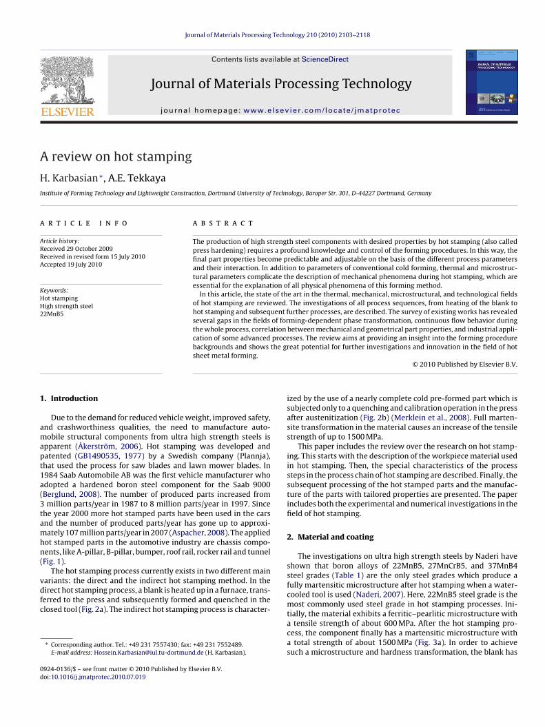
ot stamped parts in the automotive industry are chassis compo-ents, like A-pillar, B-pillar, bumper, roof rail, rocker rail and tunnelFig. 1).
The hot stamping process currently exists in two different main
ariants: the direct and the indirect hot stamping method. In theirect hot stamping process, a blank is heated up in a furnace, trans-erred to the press and subsequently formed and quenched in thelosed tool (Fig. 2a). The indirect hot stamping process is character-∗ Corresponding author. Tel.: +49 231 7557430; fax: +49 231 7552489.E-mail address: [email protected] (H. Karbasian).
924-0136/$ – see front matter © 2010 Published by Elsevier B.V.oi:10.1016/j.jmatprotec.2010.07.019
© 2010 Published by Elsevier B.V.
ized by the use of a nearly complete cold pre-formed part which issubjected only to a quenching and calibration operation in the pressafter austenitization (Fig. 2b) (Merklein et al., 2008). Full marten-site transformation in the material causes an increase of the tensilestrength of up to 1500 MPa.
This paper includes the review over the research on hot stamp-ing. This starts with the description of the workpiece material usedin hot stamping. Then, the special characteristics of the processsteps in the process chain of hot stamping are described. Finally, thesubsequent processing of the hot stamped parts and the manufac-ture of the parts with tailored properties are presented. The paperincludes both the experimental and numerical investigations in thefield of hot stamping.
2. Material and coating
The investigations on ultra high strength steels by Naderi haveshown that boron alloys of 22MnB5, 27MnCrB5, and 37MnB4steel grades (Table 1) are the only steel grades which produce afully martensitic microstructure after hot stamping when a water-cooled tool is used (Naderi, 2007). Here, 22MnB5 steel grade is themost commonly used steel grade in hot stamping processes. Ini-
tially, the material exhibits a ferritic–pearlitic microstructure witha tensile strength of about 600 MPa. After the hot stamping pro-cess, the component finally has a martensitic microstructure witha total strength of about 1500 MPa (Fig. 3a). In order to achievesuch a microstructure and hardness transformation, the blank has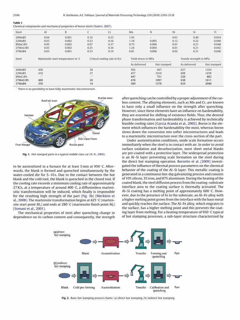
2104 H. Karbasian, A.E. Tekkaya / Journal of Materials Processing Technology 210 (2010) 2103–2118
Table 1Chemical components and mechanical properties of boron steels (Naderi, 2007).
Steel Al B C Cr Mn N Ni Si Ti
20MnB5 0.04 0.001 0.16 0.23 1.05 – 0.01 0.40 0.03422MnB5 0.03 0.002 0.23 0.16 1.18 0.005 0.12 0.22 0.0408MnCrB3 0.05 0.002 0.07 0.37 0.75 0.006 0.01 0.21 0.04827MnCrB5 0.03 0.002 0.25 0.34 1.24 0.004 0.01 0.21 0.04237MnB4 0.03 0.001 0.33 0.19 0.81 0.006 0.02 0.31 0.046
Steel Martensite start temperature in ◦C Critical cooling rate in K/s Yield stress in MPa Tensile strength in MPa
As delivered Hot stamped As delivered Hot stamped
20MnB5 450 30 505 967 637 135422MnB5 410 27 457 1010 608 14788MnCrB3 –* –* 447 751 520 88227MnCrB5 400 2037MnB4 350 14
* There is no possibility to have fully martensitic microstructure.
twwbt2sfas(
d
a higher melting point grows from the interface with the base metal
Fig. 1. Hot stamped parts in a typical middle class car (N. N., 2009).
o be austenitized in a furnace for at least 5 min at 950 ◦C. After-ards, the blank is formed and quenched simultaneously by theater-cooled die for 5–10 s. Due to the contact between the hot
lank and the cold tool, the blank is quenched in the closed tool. Ifhe cooling rate exceeds a minimum cooling rate of approximately7 K/s, at a temperature of around 400 ◦C, a diffusionless marten-itic transformation will be induced, which finally is responsibleor the resulting high strength of the part (Fig. 3b) (Merklein etl., 2008). The martensite transformation begins at 425 ◦C (marten-
ite start point Ms) and ends at 280 ◦C (martensite finish point Mf)Somani et al., 2001).The mechanical properties of steel after quenching change inependence on its carbon content and consequently, the strength
Fig. 2. Basic hot stamping process chains: (a) dire
478 1097 638 1611580 1378 810 2040
after quenching can be controlled by a proper adjustment of the car-bon content. The alloying elements, such as Mn and Cr, are knownto have only a small influence on the strength after quenching.However, since these elements have an influence on hardenability,they are essential for shifting of existence fields. Thus, the desiredphase transformation and hardenability is achieved by technicallyfeasible cooling rates (Garcia Aranda et al., 2002). Boron is the ele-ment which influences the hardenability the most, whereas boronslows down the conversion into softer microstructures and leadsto a martensitic microstructure over the cross-section of the part.
Under austenitization conditions, oxide scale formation occursimmediately when the steel is in contact with air. In order to avoidsurface oxidation and decarburization, most sheet metal blanksare pre-coated with a protective layer. The widespread protectionis an Al–Si layer preventing scale formation on the steel duringthe direct hot stamping operation. Borsetto et al. (2009) investi-gated the influence of thermal process parameters on the chemicalbehavior of the coating of the Al–Si layer. This metallic coating isgenerated in a continuous hot-dip galvanizing process and consistsof 10% silicon, 3% iron, and 87% aluminum. During the heating of thecoated blank, the steel diffusion process from the coating–substrateinterface area to the coating surface is thermally activated. TheAl–Si coating has a melting point of approximately 600 ◦C. How-ever, due to the presence of Fe in the substrate, an Al–Fe alloy with
and quickly reaches the surface. The Al–Fe alloy, which migrates tothe surface, has a higher melting point and this prevents the coat-ing layer from melting. For a heating temperature of 950 ◦C typicalof hot stamping processes, a sub-layer structure characterized by
ct hot stamping, (b) indirect hot stamping.

H. Karbasian, A.E. Tekkaya / Journal of Materials Processing Technology 210 (2010) 2103–2118 2105
and C
a(tfisspfcmhwolble(iatpbtca
iansamo
3
upbmLaa
Fig. 3. Mechanical properties of 22MnB5
n alternating variation of the chemical Al–Fe percentages appearsBorsetto et al., 2009). In the direct hot stamping process, this pro-ective layer prevents the formation of scales. Due to the lowerorming limits of the Al–Si layer compared to the base materialn the initial state at room temperature, the hot-dip aluminizedheets cannot be used for the indirect process and they are notuitable for cold forming. This coating does not provide cathodicrotection, like zinc, but a high barrier protection. Similar to coldormed parts, a cathodic protection is desirable for hot stampedomponents. These demands of the automotive industry could beet by metallic coatings with cathodic protection, e.g. zinc. During
eating and hot stamping, the hot-dip galvanized zinc layer reactsith the base material to form intermetallic zinc–iron-phases. In
rder to minimize the propagation of microcracks in the coatingayer into the base material, hot-dip galvanized 22MnB5 can onlye used for indirect hot stamping. After hot stamping, the oxide
ayer must be removed by shot peening to avoid a bad paint adher-nce. Another established protective coating for 22MnB5 is x-tec®
Goedicke et al., 2008) which is applied as a varnish in a coil coat-ng process for the direct and indirect hot stamping process withdditional active corrosion protection. This coating is based onhe combination of �m-scaled materials according to the sol–gelrocess. Inorganic and organic materials are linked together andlended with aluminum particles to form a protective coating. Theribological behavior of this 7 �m thick protective coating in theold forming operation allows a controllable material flow withoutdditional lubrication (Paar et al., 2008).
The latest method for the prevention of oxidation involves coat-ng the sheets with preventive oil, as described in the work of Morind Ito (2009). The oxidation of heated sheets in an electrical fur-ace could be prevented and the effect of two different oils wastudied. The effect of the oxidation preventive oil was evaluated incooling experiment without forming and in a hot bending experi-ent. The analysis of the sheet surface has shown that the number
f lubrications (up to 4 times) reduces the surface oxidation.
. Heating
The hot stamping process begins with the heating of the blankp to the austenitization temperature. For the determination of therocess window regarding a homogeneous austenitization of the
lanks during hot stamping as a pre-condition for the desired fullyartensitic transformation, annealing tests were performed byechler and Merklein (2008) considering austenitization temper-ture and time. In these tests, the samples were quenched throughfull metallic contact pressure of 40 MPa on both sides. To evaluate
CT diagram (Garcia Aranda et al., 2002).
the occurring phase transformations, the hardness of the quenchedblanks were measured according to Vickers HV10. The minimumaustenitization time at different austenitization temperatures anddifferent sheet thicknesses to achieve the maximum hardness of470 HV are shown in Fig. 4.
The results of this study show the significant dependency ofthe austenitization temperature (Fig. 4a) and the sheet thickness(Fig. 4b) on the minimum heat treatment time with respect to ahomogenous austenitization of the quenchable steel 22MnB5. At afurnace temperature of 950 ◦C, a dwell time of 3 min was found tobe sufficient to obtain the maximum martensitic content in thequenched samples with a maximum hardness of approximately470 HV. With decreasing furnace temperature, the austenitizationduration time increases. The upper time limit of Al–Si pre-coatedblanks is determined by means of the thickness of the alloyingternary Al–Si–Fe layer (Austerhoff and Rostek, 2002) during heattreatment with the objective to ensure a sufficiently accurate weld-ability (Stopp et al., 2007) of the hot stamped parts during postprocessing. According to the experiences from industry (Stopp etal., 2007), a layer thickness of approximately 40 �m should not beexceeded during austenitization in the furnace.
The investigations of Lechler (2009) have shown that the heatingprocedure of the blank has a great influence on the part properties,the process time, and the cost-efficiency of hot stamping. Therefore,a homogenous blank temperature and a short heating time are themain demand on the heating system. The blank can be heated usingdifferent thermal phenomena: radiation in a furnace, induction, andconduction (Fig. 5).
3.1. Roller hearth furnace
On the existing lines, the blank is usually heated in roller heathfurnaces or walking beam furnaces. The size and connected load ofthese furnaces depend on the through-put and the material to beheated. Al–Si coated materials used for preventing scale formationrequire a special heating curve due to a necessary diffusion processbetween base material and the coating (Suehiro et al., 2003).
The furnaces of the existing hot stamping lines already reachlengths of 30–40 m. The high space requirement and the risinginvestment costs show the need for alternative approaches to heatthe blanks.
The cycle time for press-hardened parts is mainly dependent
on the die closing time and the furnace residence time required toaustenitize the material and, in the case of coating, to achieve therequired through-alloying. With regard to die closing time, opti-mization of die cooling or the tool steels used could provide areduction in cycle time. A reduction in furnace residence time can
2106 H. Karbasian, A.E. Tekkaya / Journal of Materials Processing Technology 210 (2010) 2103–2118
F the ma
oelt
3
htmpJcotitoi2
eriuaol
ig. 4. Influence of austenitization temperature, time (a), and sheet thickness (b) onnd Merklein, 2008).
nly be achieved by the following faster heating concepts (Lenzet al., 2008a,b). These methods are in the development phase, andaboratory investigations must verify them for industrial applica-ion.
.2. Conduction heating
An alternative heating system is conduction heating. For theeating process, a blank is clamped between the two pairs of elec-rodes (Mori et al., 2009). The current flows through the sheet
etal part. The resistance of the material causes the heating of theart. The conduction heating of the metallic substances is based on
oule’s Law, according to which the heat generated in an electricircuit is proportional to the power of the electric circuit. The lossf power due to the electrical resistance of the conductors results inhe conductors themselves being heated. A low surface quality andnsulating pollution layers on the component increase the resis-ance and thus the heat generation in the contact area. The designf these contacts and the control of the contact pressure are crit-cal for the homogenous heating of the component (Kolleck et al.,008).
An important basis for the use of conduction heating is thefficiency factor. This parameter directly depends on the part’sesistance. Because of the higher resistance of long components
n comparison to short components, conduction heating is mainlysed for components with a favorable length/diameter ratio, suchs pipes, rods, wires, and bands (Kolleck et al., 2008). Disadvantagef this heating system is the inhomogeneous temperature along theength of the component. Another problem for the industrial appli-Fig. 5. Heating systems: (a) roller hearth furnace, (
inimum austenitization time to achieve the maximum hardness of 470 HV (Lechler
cation of this heating method is the difficulty of heating blanks withcomplex geometries homogeneously (Behrens et al., 2008).
3.3. Induction heating
The last heating system is the inductive heating of the blank. Inprinciple, all electrically conducting or semiconducting substancescan be heated by induction, and the resulting area of application iscorrespondingly large for this technology: melting of metals, bulkforming and tempering, and assembly and packaging industry. Thegeometry of the inductor determines the position of the magneticfield relative to the workpiece, which causes different degrees ofefficiency. The distance between inductor and sheet also has aninfluence on the efficiency of the heating system. On the one hand,the electrical insulation between inductor and sheet must be guar-anteed; on the other hand, shaped blanks tend to go out of shapewhile being heated. A small distance to the inductor can cause thejamming of the heated blank with the risk of damaging the heatingsystem (Kolleck et al., 2009a,b). Compared to roller heath furnaces,the energy efficiency of induction heating is up to two times higher,because of the higher losses of the roller heath furnace by exhaustgases and the rollers.
4. Forming
In order to avoid cooling of the part before forming, the blankmust be transferred as quickly as possible from the furnace to thepress. Furthermore, forming must be completed before the begin-ning of the martensite transformation. Therefore, a fast tool closing
b) induction heating, (c) conduction heating.

H. Karbasian, A.E. Tekkaya / Journal of Materials Pr
aciIhs
mfontttLppalafbw
mtae2(t
4
npdrtflnhwFc
Fig. 6. Tool design for the hot stamping process.
nd forming process are the precondition for a successful processontrol. After forming, the part is quenched in the closed tool, whichs cooled by water ducts to transfer the heat out of the tool system.n order to avoid the quenching of the blank between the blankolder and the die during the forming process, most of the hottamping tool systems work with a distance blank holder (Fig. 6).
Another process variant is hot stamping by means of workingedia. The use of temperature as a process parameter in hot gas
orming and a simultaneous quenching of the formed parts offer thepportunity to increase the application field of this innovative tech-ology (Neugebauer et al., 2009). The forming procedure starts withhe positioning of the profile or the blank. After the tool is closed,he forming step is performed using the working media (Fig. 7). Inhe work of Neugebauer et al. (2009), nitrogen, and in the work ofindkvist et al. (2009), air is used as the working medium with aressure of up to 600 bar. The advantage of hot gas forming in com-arison to conventional hot stamping is the free forming of the partt the beginning of the forming process. In addition, because of theower contact time between the part and the tool during forming,homogenous blank temperature distribution leads to a uniform
orming of the blank. Another interesting field in gas forming maye the application of thermally insulating and/or incompressibleorking media.
The current strong demand for a higher efficiency of hot sheetetal forming processes inevitably leads to the question of how
o shorten the process cycle. Cooling can be accelerated by thepplication of tool steels with improved heat conductivity (Casast al., 2008) and/or more efficient cooling systems (Hoffmann et al.,007). By the application of the tool steels developed by Casas et al.2008) with a thermal conductivity of up to 66 W/mK, the holdingime could be reduced from 10 to 2 s.
.1. Cooling ducts
The quenching operation during the hot stamping process doesot only influence the economy of the process but also the finalroperties of the component. The objective of the cooling ductsesign is to quench the hot part effectively and to achieve a coolingate of at least 27 K/s while martensite forms. The die cooling sys-em is economical if a fluid coolant, such as water, is used, whichows through cooling ducts around the contours of the compo-
ent. The heat flow in the formed component is dependent on theeat transfer from the component to the tool, the heat conductivityithin the tool, and the heat transfer from the tool to the coolant.or an optimum heat transfer between component and tool, theontact surface should not exhibit a scale or a gap. The heat conduc-
ocessing Technology 210 (2010) 2103–2118 2107
tivity within the tool can be considerably influenced by the choiceof the tool material. Another important factor with respect to heatdrain is the design of the cooling ducts, which is defined by the size,location, and distribution of the cooling ducts. The heat drain can beaccelerated by using a coolant with a low temperature in order toincrease the temperature difference between the coolant and thetool and therefore the resulting heat flux (Steinbeiss et al., 2007).
The cooling holes can be drilled in the forming tool. For thismethod, the machining restrictions should be considered in thedesign of the hole position (Steinbeiss et al., 2007). Therefore, anoptimal design of the cooling system as to heat transfer is notpossible. Another alternative is to provide the cooling holes aspipes in the casting mold of the tool (Kuhn and Kolleck, 2006).The unrestricted design of the cooling system is the advantage ofthis method. Alternatively, the tools can be manufactured usingthe lasered blank segments, which are screwed and form the toolsurface with integrated cooling holes (Freieck, 2007). This methodis very cost-effective, but the lamellar design can have negativeeffects on the part surface and the heat transfer within the tool.
4.2. Wear of the tool surface
The wear resistance of the tool has been measured by Dessain etal. (2008) using a strip drawing equipment which is adapted to hightemperature tests. The resistance heating device allows heating upthe Al–Si coated 22MnB5 strip. The heated strip slides over the dieradius. For this test, the contact surface was made of abrasion andadhesion areas. The die abrasion was predominant and adhesion ofAl–Si was observed at the end of the contact area with the blank.These built layers, formed very early at the beginning of the test, areknown to form compacted layers on the tool surface during slidingof the strip (Hardell and Prakash, 2008) and exhibited low wear.
The exposure of the tool steel to high temperatures in a hot form-ing operation can result in large variations in friction due to changesin the surface topography, removal of oxide layers and excessivewear of the tool. One approach to overcome friction problems is toapply suitable surface treatments and/or coatings to the tool steelwith. Tribological studies by Hardell and Prakash (2008) at roomtemperature and 400 ◦C on one plasma nitrided tool steel and twoPVD coatings (CrN and TiAlN) sliding against UHSS were carried outusing a pin-on-disc machine. The best results as to wear resistancewere achieved by the TiAlN coating.
Comparable studies for another sheet coating do not exist. Fur-thermore, the austenitization time and its influence on the surfacetexture must be considered in design of experiments for furtherinvestigations.
5. Quenching
After the forming of the heated blank in the austenitic temper-ature range, the part is quenched in the closed tool until the entiremartensite transformation of the part structure is completely. Acooling rate of more than 27 K/s is necessary for a full marten-site microstructure of 22MnB5. Martensite evolution leads to anincrease of the flow stress (Fig. 8). The transformation from austen-ite (fcc) into martensite (bct) causes an increase in volume, whichinfluences the stress distribution during quenching. Only the com-plete description of the transformation behavior allows a predictionof the resulting material properties, the volume fraction of differentphases, the residual stresses, and the distortion of the workpiece
after cooling (Neubauer et al., 2008).For the modeling of the thermoplastic transformation behavior,the strain increment can be described by the sum of elastic, plastic,thermal, and isotropic transformation and transformation-inducedplasticity strains (Table 2). Due to the different lattice structures of

2108 H. Karbasian, A.E. Tekkaya / Journal of Materials Processing Technology 210 (2010) 2103–2118
f profi
anttlosotaa
mutui(tfpTit
iug
Fig. 7. Gas forming o
ustenite and the resulting microstructures ferrite, pearlite, bai-ite and martensite, a volume change occurs during the phaseransformation that can be described by means of the isotropicransformation strains. This effect causes only a change in volume,ike the thermal strain increment. Additionally, the morphologiesf these microstructural components are very different, and con-equently their mechanical properties differ. Therefore, the studyf material macroscopic behavior becomes a difficult homogeniza-ion problem due to the fact that new phases continuously evolvend the deformation history must be accounted for (Åkerström etl., 2007).
If the phase transformation occurs without applied stress, theaterial response is purely volumetric and an increase in vol-
me is observed due to the compactness difference betweenhe parent and product phase. When the transformations occurnder an external stress, transformation-induced plasticity causes
rreversible deformation. The Greenwood–Johnson mechanismGreenwood and Johnson, 1965) describes the transformation plas-icity which depends on the austenite and the resulting phaseraction. Therefore, micro-stresses are introduced that generatelastic strains in the austenite when deviatoric stress is applied.he commonly used model considering the transformation plastic-ty is the model by Leblond et al. (1989), which was further applied
o numerical modeling by Åkerström (2006).The described analytical model for the flow behavior can be ver-fied using the continuous cooling transformation diagrams (CCT)nder different forming modes. To determine the forming CCT dia-ram (FCCT), the heated specimen is formed until it reaches the test
Fig. 8. Flow curves and microstructure
le (a) and sheet (b).
forming condition and is subsequently cooled at a predeterminedrate. The degree of transformation is measured.
6. FE simulation
Hot stamping is a thermo-mechanical forming process withintended phase transformation. Depending on the temperaturehistory and mechanical deformation, different phases and phasemixtures evolve. During the solid-state phase transformations,heat is released, which influences the thermal field. Further-more, depending on the mixture of micro constituents, both themechanical and thermal properties vary with temperature anddeformation. Consequently, a realistic FE model for process simu-lation must consider interaction between the mechanical, thermal,and microstructural fields (Fig. 9). This requires process character-istics like the heat transfer coefficient, the material flow behavior,and the phase transformation under process-relevant conditions(Oldenburg, 2008). Due to the transfer of microstructural evolu-tion data within the process simulation, final properties, such ashardness and tensile strength, can be properly modeled (Jeswiet etal., 2008).
For a consistent analysis of coupled thermo-mechanical defor-
mations of metals, Ghosh and Kikuchi (1988) developed a finiteelement method, which models the flow behavior of metals atelevated temperatures. The proposed model considers the initialanisotropy and temperature dependence of metals for large-deformation forming processes.of 22MnB5 during hot stamping.

H. Karbasian, A.E. Tekkaya / Journal of Materials Pr
Table 2Strain rate components in hot stamping.
Total strain rate εij = εelij
+ εplij
+ εthij
+ εtrij
+ εtpij (1)
εelij
: elastic component, εplij
: plastic
component, εtpij
: trans. plasticity, εthij
, εtrij
:thermal and isotropic transformationcomponent
Thermal and isotropictransformation component(Olle et al., 2008)
dεth+trij
= dεthij
+ dεtrij
=(at+�t
n
(Tt+�t
)at
n (Tt )− 1
)ıij (2)
an: lattice constant, �t: time step, ıij:Kronecker delta, T: temperature
Transformation plasticity rate(Åkerström, 2006)
εtpij
= −3�εth
1−2h(
��y
)z ln (z)
�y1
(εp
1, T) sij (3)
h
(�
�y
)=⎧⎪⎨
⎪⎩1
�
�y≤ 1
2
x + 3.5
(�
�y− 1
2
)�
�y>
12
�εth1−2: difference in compactness between
austenite and the resulting phase, �y1:
current yield stress of austenite, z: volumefraction of resulting phase, sij: deviatoricstress, h: correction function according tothe nonlinearity in the applied stress, �:current effective stress, �y: current globalyield stress
Volume fraction of martensite(Koistinen and Marburger,
zM (t) = 1 − e
(−a(TMS−T)�
)(4)
shatccwitaiF
F(
1959)TMS: martensite start temperature, a, �:coefficients
In recent years, several concepts of coupling two FE programspecializing in their own respective domains for the performance ofot stamping have been developed. The coupled systems considerthermal and a mechanical model, which are linked to achieve the
ransfer of geometrical and physical data. Because of the separatealculation of thermal and mechanical phenomena, the couplingoncepts are very flexible and efficient for parameter adjustmentsithin the FE models. The disadvantage of this method is the lim-
ted data transfer between the two FE models, which can influence
he accuracy of the results of the simulation (Hein, 2005; Tekkaya etl., 2007). Another alternative for the FE simulation of hot stampings the application of special purpose programs: LS-DYNA, Auto-orm, and PamStamp. The FE models vary in the existing options forig. 9. Interaction between thermal, mechanical, and microstructural fieldsBergman, 1999).
ocessing Technology 210 (2010) 2103–2118 2109
the definition and description of the physical processes. For exam-ple, the analysis with the FE software LS-DYNA can be performedusing thermal shell elements coupled with mechanical shell ele-ments for the metal sheet (Bergman and Oldenburg, 2004). Thethermal problem is solved by the implicit time integration whilethe mechanical problem is processed by the explicit time integra-tion method. This feature within LS-DYNA allows to combine theadvantages of each integration rule and, at the same time, over-come contact solution stability and thermal convergence. The toolscan be modeled as rigid bodies with thermal behavior (Karbasianet al., 2008a,b).
The prediction of the temperature distribution in the blank andthe tools plays a very important role in this process. A temperature-dependent hardening function is also required to characterize theplastic deformation and to take into account the heat between theblank and the tools as well as heat loss due to convection andradiation from the blank. The phase transformation from austen-ite to martensite must also be considered in order to simulate thehot forming process (Åkerström et al., 2007). In the following, thethermo-mechanical properties and their determination for the FEsimulation of hot stamping are described.
6.1. Thermal characteristics
The prediction of the mechanical properties of hot stampedparts by means of FE simulation requires an accurate modeling ofthe thermal phenomena during forming and quenching. The heattransfer coefficient h is responsible for the thermal behavior andthe respective cooling of the blanks throughout the whole form-ing operation and can be influenced by the contact pressure andthe temperature of the steel sheet as well as the surface condition(scale thickness, roughness, coating thickness, etc.) (Forstner et al.,2007). As the mechanical properties of the base material 22MnB5are strongly dependent on the temperature, this is one of the mostimportant parameters to be taken into account regarding FE mod-eling of thermally assisted forming.
For the determination of the heat transfer coefficient, a quench-ing tool has been developed by Hoff (2007). The heated blank wasquenched between two water-cooled plates at a defined contactpressure. During the test, the temperatures of the blank and of bothcontact plates were recorded. On the basis of the measured param-eters, the heat transfer coefficient was calculated in dependenceon the contact conditions using an analytical method according toNewton’s cooling law.
T(t) = (T0 − T∞)e(−h(A/cp�V)t) + T∞ (5)
A: contact surface, cp: heat capacity, h: heat transfer coefficient, V:volume, t: time, T0: initial temperature, T∞: environmental tem-perature, �: density
The evaluation of the heat transfer coefficient h as a function ofthe increasing contact pressure shows the significant influence ofthe applied load on the heat exchange between workpiece and die(Fig. 10). Increasing the contact pressure leads to an increase of theheat transfer. This effect is related to the rise in the effective con-tact surface between the two contact partners through smoothing,in particular of the case in the Al–Si coated sheets. Consequently,more and more real metallic–metallic contact areas occur enforc-ing direct heat conductance effects, through which more thermalenergy between the two contact bodies is transferred (Karbasian etal., 2008a,b).
6.2. Flow behavior
The flow behavior of steel 22MnB5 was characterized usinga conductive hot tensile test by Merklein and Lechler (2006)to determine the material thermo-mechanical properties underprocess-relevant conditions (Fig. 11). This investigation showed

2110 H. Karbasian, A.E. Tekkaya / Journal of Materials Processing Technology 210 (2010) 2103–2118
fficie
ta2
rtcopa
6
oshodTodept(
tmsN
Fig. 10. Heat transfer coe
hat not only strain but also strain rate temperature and temper-ture rate have the greatest influence on the flow properties of2MnB5 at elevated temperatures in the austenitic state.
Apart from the significant impact of the temperature and strainate on the thermo-mechanical properties in the conductive tensileests, the dependency of the temperature on the plastic anisotropyould be detected (Merklein and Lechler, 2008). At a temperaturef about 800–850 ◦C, the sheet metal exhibits an almost isotropiclastic behavior. Because of austenitization, the influence of thenisotropy can be neglected (Merklein and Lechler, 2008).
.3. Material models
For the thermo-mechanical forming processes, a large varietyf semi-empirical as well as physically based models for the flowtress have been proposed. The existing models in Table 3, thatave shown a good capability of representing the flow behaviorf 22MnB5 in recent publications, are fitted to the experimentalata by Hochholdinger et al. (2009) and Durrenberger et al. (2009).he experimental data for the determination of the flow stress arebtained by an upsetting test, which was conducted in a high-speedeformation dilatometer (Hochholdinger et al., 2009). The param-ter estimation of some of the material models in Table 3 are notublished in the cited references. But the other material data likehose of Johnson–Cook and Norton–Hoff can be found in Åkerström2006) and Lechler (2009).
Hochholdinger et al. (2009) have shown that the best fit ofhe experimental data can be achieved with the Tong–Wahlen
odel. Fig. 12a shows the failure in the saturation of the flowtress increases at higher values of the effective plastic strain inorton–Hoff and the Nemat–Nasser model.
Fig. 11. (a) Experimental setup and (b) flow
nts in hot sheet forming.
The values of the flow stress at relatively large strains representthe main disadvantage of the Johnson–Cook model in the work ofDurrenberger et al. (2008, 2009) (Fig. 12b). The predictions of theVoce–Kocks relation are in good agreement with the experimentaldata, the model predicts an early saturation of the flow stress at astrain of about 0.06, while a slight strain-hardening is still observedin experiments. The Molinari–Ravichandran model has the capac-ity to reproduce history effects, such as rapid changes in strain rateor temperature history, by means of the evolution law of the inter-nal parameter. However, for the material 22MnB5 analyzed in thisstudy, the Molinari–Ravichandran model predicts an early satu-ration of the flow stress after a plastic strain of about 0.10. Thepredictions of the Ghost model are in good agreement with theexperimental data of 22MnB5 up to a plastic strain of about 0.05.
A continuous model of the flow behavior, which includes anddescribes the phase transformation up to the end of the martensiteevolution, is developed and implemented in a finite element simu-lation by Åkerström et al. (2007). The created model describes thethermo-mechanical material properties on the basis of the actualphase structure considering latent heat, volume change and trans-formation plasticity during phase transformation (Åkerström et al.,2005). The comparison of the material models with the experimen-tal data has shown that the realistic modeling of the flow behaviorof 22MnB5 in the austenite condition is possible.
6.4. Forming limit curve
The description of the material formability by sheet metal form-ing is traditionally achieved through the approach of forming limitcurves FLC. This curve shows necking and fracture in the deformedsheet at different stress states on sheet samples from balanced
curves (Merklein and Lechler, 2006).

H. Karbasian, A.E. Tekkaya / Journal of Materials Processing Technology 210 (2010) 2103–2118 2111
Table 3Material models for 22MnB5.
Åkerström (2006) Nemat-Nasser (1999) �f = �0
{1 −[
− kT
G0
(ln
ε
ε0+ ln f (εp, T)
)]1/q}1/p
f (εp, T) + �0a εn
p (6)
f (εp, T) = 1 + a0
[1 −(
TTm
)2]
ε1/2p
�0: effective stress, k: Boltzmann constant p, q: shape of energy barrier, ε0: referencestrain, G0: magnitude of activation energy, T: temperature
Johnson and Cook (1983) �f = (A + Bεn)
[1 + C ln
(ε
ε0
)][1 −(
T − T0
Tf − T0
)m]with T ≥ T0 (7)
A, B, C, n, m: coefficients of the model, ε0: reference strain rate, T: temperature, T0:reference temperature, T: melting temperature
Hochholdinger et al. (2009) Norton (1929) and Hoff (1954) �f = K(b + ε)n0 exp[−cn(T−T0)]εm0 exp[cm(T−T0)] exp
(ˇ
T
)(8)
K, ˇ, b, n0, m0, cn , cm: coefficients of the model, T: temperature, T0: reference temperature
Tong et al. (2005) �f = A
[εm1(T−T0) exp
(m2Q
RT
)][1 − ˇ exp
(−Nεn
p
)](9)
A, m1, m2, N, ˇ: constants of the model, R: gas constant, Q: activation energy, T:temperature, εp: strain rate
Durrenberger et al. (2009) Ghost (Bouaziz et al., 2004) � =(
�0 + Ma�b√
�)(
1 + kT
b3vaarsh
[ε
ε0exp
(Q
RT
)])(10)
M: Taylor factor, ˛: dislocation parameter, �: shear modulus, b: Bürgers vector, �0:dislocation density, k: Boltzmann constant, R: gas constant, �0: friction resistance, va:shear stress, ε0: reference strain rate
Molinari and Ravichandran (2005) �f = �0
(ε
ε0
)1/m
with �0 = � (d)
(ı0
ı
)(11)
ε: strain rate, ε0: reference strain rate, �0: intrinsic resistance, m: instantaneous materialsensit
�S +atura
bvnm2
pcmmdibs
iH
rate
Voce–Kocks (1976) �f =�s: s
iaxial to pure shear. However, when forming take places at ele-ated temperatures, the material formability is greatly influencedot only by the strain but also by temperature, strain rate, andicrostructural evolution during deformation (Pellegrini et al.,
009).Several tests have been developed and applied for this pur-
ose, with the Marciniak and the Nakajima tests being the mostommonly applied ones. In both tests, the sheet metal – in theetastable austenitic phase – undergoes thermo-mechanical treat-ents, that are carried out at different temperatures and follow
ifferent paths of strain and strain rate until the onset of neck-ng and fracture occurs (Bariani et al., 2008). The main difference
etween these tests is the shape of the punch, which is either hemi-pherical or flat (Dahan et al., 2007).Forming limit curves of the material 22MnB5 were measuredn the Nakajima tests at elevated temperatures in different studies.ere, for the determination of the temperature-dependent form-
Fig. 12. Flow curves of different models
ivity, d: grain size, T: temperature[(�0 − �S) exp
(− ε
εr
)](12)
tion stress, �0: initial yield stress, εr: relaxation strain
ing limit curves, the traditional test equipment has to be modified.Therefore, special heating cartridges have to be introduced in thepunch, the die, and the blank holder to control the temperature ofthe setup.
Pellegrini et al. (2009) have shown that the thermally inducedimprovement of the material and higher values of the slip systemsof austenite in comparison to the initial ferrite-pearlite microstruc-ture are the cause of the evolution of the mechanical propertiesduring hot stamping (Fig. 13). The main reasons for the scatteringof the analyzed results are the different procedure and the evalua-tion tests at elevated temperatures. The heating method by Lechler(2009) ensures a uniform distribution of the blank temperature
during the heating phase in the furnace, but implies a more dif-ficult control of the temperature during cooling due to the manualtransfer to the press. The induction heating of Pellegrini et al. (2009)leads to a less uniform distribution of the temperature but also toa good cooling control.for 22MnB5 and the experiments.

2112 H. Karbasian, A.E. Tekkaya / Journal of Materials Pr
(bs
aLdHdhlgttpfaur2
6
stac
testing machine consists of a furnace and a drawing device with an
Fig. 13. Forming limit curves of 22MnB5.
Similar to cited works of Pellegrini et al. (2009) and Lechler2009), Chastel et al. (2008) have shown that the higher the initiallank temperature or the sheet thickness, the higher the criticaltrain in plane strain.
In the existing works, heating and cooling of the blank areccomplished by different methods. On the one hand, in the work byechler (2009), the heating method ensures a uniform temperatureistribution on the blank during the heating phase in the furnace.owever, this implies a more difficult control of the temperatureuring cooling due to the manual transfer to the press. On the otherand, the induction heating used in the work by Bariani et al. (2008)
eads to a less uniform distribution of temperature but allows aood cooling control, ensuring very high cooling rates. Therefore,he difficulty in carrying out tests under real isothermal condi-ions at high enough cooling rates to ensure the avoidance of anyhase transformation is evident. The issue of evaluating sheet metalormability at elevated temperatures can be accomplished throughn alternative approach, based on the application of a proper fail-re criterion that can be developed as a function of strain, strainate, temperature, and microstructural evolution (Pellegrini et al.,009).
.5. Friction coefficient
The friction characteristics of the coated material used in hot
tamping can be evaluated by different test methods (Fig. 14). Theesting methods vary in the contact condition between the sheetnd the tool, which is important for the determination of the frictionoefficient and must be similar to hot stamping conditions.Fig. 14. Principle of the test methods for the
ocessing Technology 210 (2010) 2103–2118
An experimental–analytical–numerical evaluation method wasused by Stöhr et al. (2008) to determine the friction coefficientunder process-relevant conditions. Here, the cup deep drawingtest (Fig. 14a), following the time–temperature profile of the hotstamping process, acted as experimental basis. To reveal differ-ent thermal conduction rates during the experiments with theobjective to investigate the impact of the temperature on thetribological conduction rates, the temperature of the tool wasvaried. In this work, the friction values determined for Al–Sicoated 22MnB5 specimens were calculated by Siebel’s approach(Siebel and Beisswänger, 1955). The results (Fig. 15) show asignificant decrease of the friction coefficient with rising tem-perature, with the values ranging from 0.6 to 0.3 (Stöhr et al.,2008).
The pin-on-disc test (Fig. 14b) was performed by Ghiotti et al.(2009a,b) and by Hardell and Prakash (2008) to investigate theinfluence of the process parameters (i.e. temperature, pressure,sliding velocity and roughness) on the friction at the interfacebetween the sheet metal blank and the dies. The analysis hasshown that the interaction between the temperature and thepressure is the most relevant one for the friction coefficient inhot stamping. Both studies have shown that the friction valueof the interface decreases with increasing temperature and nor-mal pressure. This fact may be explained by the formation of theintermetallic Fe–Al, which is responsible for the friction reduc-tion when increasing normal pressure is applied (Ghiotti et al.,2009a,b). The contact condition between the blank and the toolin the pin-on-disc method is different from the contact conditionin sheet metal forming. Therefore, the determined values of up to0.8 (Fig. 15) using this method are not suitable for the applicationin sheet metal forming under the corresponding surface contactcondition.
Another method for the determination of the friction is thedrawing test (Fig. 14c), which was carried out by Dessain et al.(2008). The heated sheet is drawn through the convex contactarea of the tool with a simultaneous measurement of the forces indifferent directions. The friction coefficient is calculated from themeasured forces according to Pawelski (1964). A comparison of theresults for the friction coefficient at a constant pressure of 10 MPaand a constant austenitization time in the furnace of 390 s revealsthat different temperature values have only a small influence on thefrictional behavior of the tribological system (Fig. 15). The same istrue for a higher surface pressure value of 25 MPa (Dessain et al.,2008).
The last method used to evaluate the friction coefficient is stripdrawing (Fig. 14d), applied by Yanagida and Azushima (2009). The
integrated blank holder. The friction coefficient is calculated fromthe blank holder force and the tension force. In contrast to othercited investigations, the calculated friction coefficient of 0.5 up to0.6 increases with increasing temperature at a constant pressure of
evaluation of friction characteristics.

H. Karbasian, A.E. Tekkaya / Journal of Materials Pr
1ao2
ficvcdh
7
tfmiimfp
t(sct
rflat
suitable for the direct process. One of the goals is to combine the
Fig. 15. Friction coefficient against temperature.
0 MPa (Fig. 15). The variation of the contact pressure between 7nd 14 MPa has shown that the friction coefficient is independentf the contact pressure within this range (Yanagida and Azushima,009).
The results of the different investigations on the friction coef-cient of Al–Si coated 22MnB5 (Fig. 15) show that the contactondition during the test has a great influence on the calculatedalues. In comparison to the real hot stamping process, the contactonditions are similar to those in deep drawing (Fig. 14a) and striprawing under bending (Fig. 14e). The strip drawing under bendingas not been used for the determination of the friction coefficient.
. Final properties
The martensite evolution during quenching causes an increasedensile strength of up to 1500 MPa, which is verified in dif-erent works using tensile tests (Naderi, 2007) and hardness
easurements (Åkerström, 2006). The subsequent microstructurenvestigations have shown that the full martensite transformations the precondition for the increased mechanical strength of the
aterial. Due to the effect of the cooling rate and the phase trans-ormation, the final mechanical properties are dependent on therocess control.
In a continuous cooling process, cooling rate and hardness arehe relevant parameters. In a practical approach, Erhardt and Böke2008) used the cooling gradients, calculated in the hot formingimulation, to determine a value of hardness and other mechanicalharacteristics of the part. The mechanical properties depend onhe thermal and forming history of the part.
The flow curves of 22MnB5 at different temperatures and strain
ates show the strong influence of these process parameters on theow behavior of the material. Although temperature and strain ratere varied along the part surface and process in the course of theime, the studies of Yanagimoto and Oyamada (2007) and KusumiFig. 16. B-pillar with tailored proper
ocessing Technology 210 (2010) 2103–2118 2113
et al. (2009) have shown the high shape accuracy of the hot stampedparts with minimal springback.
For the description of the thermo-mechanical phenomena dur-ing hot stamping and their background, the analysis of residualstress is required. In further investigations, the analysis of thestress fractions due to thermo mechanical and microstructuralprocedures can be the dominant process parameters with regardto the part properties. This knowledge is also essential for thedistortion-free manufacturing of hot stamped parts with tailoredproperties.
7.1. Corrosion
The same cathodic protection of cold formed parts is desirablefor hot stamped parts. The surface of the Fe–Al alloy phase of hot-dip aluminized sheets after the heat treatment is rough, and thanksto an anchoring effect of the surface, its paintability is good withoutchemical treatment. The Fe–Al alloy phase exhibits a better corro-sion resistance than a steel sheet without surface treatment andan almost equivalent corrosion resistance to that of a galvannealedsteel sheet (Suehiro et al., 2003). It must be pointed out that theAl–Si coating does not provide cathodic protection like zinc but ahigh barrier protection.
For the corrosion tests with x-tec coated blanks, it has been clar-ified that the corrosion does not come from the steel basic materialand is not produced by iron diffused into the coating during theannealing process (Goedicke et al., 2008). To ensure weldabilityand paint adherence, the x-tec® coating has to be removed afterpress hardening by shot blasing (Paar et al., 2008).
The measured protection against perforation corrosion of aphs-ultraform® (Zn–Fe coated) blank shows that the Zn–Fe coat-ing performs significantly better than conventional zinc coatings.This is due to a slightly higher electrochemical potential in thiscoating and more stable corrosion products (Faderl et al., 2008).Also in terms of paint delamination, the discussed Zn–Fe coat-ing is superior to conventional galvanized coatings as long asthe surface is properly conditioned. Red-colored corrosion prod-ucts (yellow rust) may occur as a result of the iron content inthe protective coating, analogously to galvannealed coatings. Thecross-section of the corroded sample clearly demonstrates that thebase steel has not been attacked for a very long time (Faderl et al.,2009).
The subject of the current investigations is the continuousimprovement of established coatings and the development of newor modified metallic coatings with an active corrosion protection
high thermal stability of Al–Si coatings with the cathodic protec-tion of Zn coatings for the direct and indirect process. Another goalis to avoid intercrystalline cracks during hot stamping by usingprealloyed zinc coatings (Paar et al., 2008).
ties (Erhardt and Böke, 2008).
2114 H. Karbasian, A.E. Tekkaya / Journal of Materials Processing Technology 210 (2010) 2103–2118
mping
8
paIqa
8
aic
8
lsntitbpm
8
scsscceoaptic
s
et al., 2008).The most cost-effective cutting method is pre-developed blank-
ing. This method requires a certain blank design to achieve thedesired part outline after forming (Kolleck et al., 2009a,b). The tol-
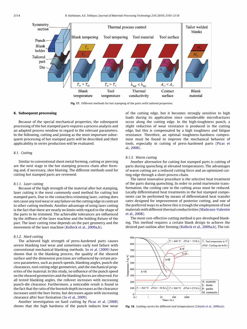
Fig. 17. Different methods for hot sta
. Subsequent processing
Because of the special mechanical properties, the subsequentrocessing of the hot stamped parts requires a process analysis andn adapted process window in regard to the relevant parameters.n the following, cutting and joining as the most important subse-uent processing of hot stamped parts will be described and theirpplicability in series production will be evaluated.
.1. Cutting
Similar to conventional sheet metal forming, cutting or piercingre the next stage in the hot stamping process chain after form-ng and, if necessary, shot blasting. The different methods used forutting hot stamped parts are reviewed.
.1.1. Laser cuttingBecause of the high strength of the material after hot stamping,
aser cutting is the most commonly used method for cutting hottamped parts. Due to the contactless trimming laser, cutting doesot cause any tool wear or any failure on the cutting edge in contrasto other cutting methods. Another advantage of using laser cuttings the fact that there are nearly no limits with regard to the shape ofhe parts to be trimmed. The achievable tolerances are influencedy the stiffness of the laser machine and the holding fixture of theart. The laser cutting time depends on the part geometry and theovement of the laser machine (Kolleck et al., 2009a,b).
.1.2. Hard cuttingThe achieved high strength of press-hardened parts causes
evere blanking tool wear and sometimes early tool failure withonventional mechanical blanking methods. So et al. (2009) havehown that in the blanking process, the quality of the shearedurface and the dimension precision are influenced by certain pro-ess parameters, such as punch speeds, blanking angles, punch-dielearances, tool cutting edge geometries, and the mechanical prop-rties of the material. In this study, no influence of the punch speedn the sheared geometries and the blanking forces are observed. Forll tested blanking angles, the rollover increases with increasingunch-die clearance. Furthermore, a noticeable result is found in
he fact that the ratio of the burnish depth increases as the clearancencreases until the burr forms, but decreases again with increasinglearance after burr formation (So et al., 2009).Another investigation on hard cutting by Picas et al. (2008)hows that the high hardness of the punch induces low wear
of the parts with tailored properties.
of the cutting edge, but it becomes strongly sensitive to highloads during its application since considerable microfracturesoccur along the cutting edge. In the high-toughness punch, aslight reduction of wear resistance is produced in the cuttingedge, but this is compensated by a high toughness and fatigueresistance. Therefore, an optimal toughness-hardness compro-mise must be found to improve the mechanical behavior oftools, especially in cutting of press-hardened parts (Picas etal., 2008).
8.1.3. Warm cuttingAnother alternative for cutting hot stamped parts is cutting of
parts during quenching at elevated temperatures. The advantagesof warm cutting are a reduced cutting force and an optimized cut-ting edge through a short process chain.
The latest innovative procedure is the selective heat treatmentof the parts during quenching. In order to avoid martensite trans-formation, the cooling rate in the cutting areas must be reduced.Locally differentiated heat treatments in the hot stamped compo-nents can be performed by means of differentiated heat transferrates designed for improvement of posterior cutting, and one ofthe preferred ways to achieve this is trough the employment of toolmaterials with different thermal conductivities (Maikranz-Valentin
Fig. 18. Cooling curves for different tool temperatures (Ghiotti et al., 2009a,b).

H. Karbasian, A.E. Tekkaya / Journal of Materials Processing Technology 210 (2010) 2103–2118 2115
austen
ef
8
owaitar
hape
wpbaoas(
Fig. 19. Mechanical properties at different
rances that can be achieved are smaller than with cutting after hotorming.
.2. Joining
Because of the low formability, the joining by forming meth-ds cannot be applied for joining hot stamped parts. Therefore,eldability of the hot stamped parts is the precondition for the
pplication of the parts in practice. The coating layer and its chem-cal composition can cause failures during welding. In the following,he investigations on resistance spot welding, laser and gas metalrc welding of the material 22MnB5 with different coatings areeviewed.
The aluminum plating layer of the product is transformed duringeating before being press-formed into a Fe–Al alloy phase havinghigh melting point, and, thanks to this, the spot-weldability of theroduct is not affected by the presence of coating layers (Suehirot al., 2003).
The first generation scale protection, e.g. x-tec®, is not spot-eldable and must therefore be removed by sandblasting from theress-hardened parts before further processing. The reason for thisehavior is that the electric resistance of the anti-scaling coating
fter the hot stamping process is too high to permit a sufficient flowf welding current. The test of second and third generation x-tec®nti scaling coatings by the integration of magnesium particles hashown the suitability of the coatings for resistance spot weldingGoedicke et al., 2008). Resistance spot welding (RSW) of x-tec®
Fig. 20. Hot stamped parts in autom
itization temperatures (Stöhr et al., 2009).
coated blanks has shown that the applied atmosphere inside thefurnace while heating the blanks has a great influence on the spot-weldability. The O2 content was found to be the main driver here.Heating in air causes the formation of oxide layers so that spotwelding cannot be applied. Applying a nitrogen atmosphere leadsto very low oxide percentages inside the coated layer after heatingand forming, and thus supports spot welding (Braun and Fritzsche,2009).
For Zn–Fe coatings, the best resistance spot welding results areproduced with the double-pulse technology in combination witha DC source (Faderl et al., 2009). The other methods of joining arealso possible, such as SG welding, SG brazing, laser and stud welding(Faderl et al., 2009).
For laser and gas metal arc welding, the cross-sections of thejoints of the tested combinations show that the x-tec® coating hadno influence on the welding behavior. No pores or other defectswere detected inside the joints with and without overlap. This coat-ing will flexibly work also with different substrates, e.g. H430LA formanufacturing tailor welded blanks (Braun and Fritzsche, 2009). Inorder to avoid the diffusion of Al and Si into the weld seam, whenthe hot-dip aluminized sheets are used, the coated layer must beremoved about 2 mm along the weld seam.
9. Hot stamped parts with tailored properties
The fully martensitic transformation during hot stamping of theparts leads to a tensile strength of up to 1500 MPa and a low elon-
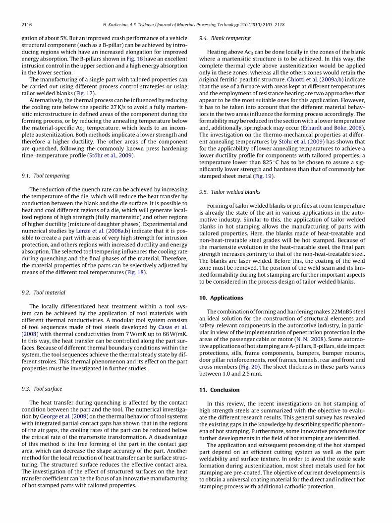
otive industry (N. N., 2008).
2 ials Pr
gsdeii
bt
tsftptat
9
tchionspadtm
9
tdo(Ifsfp
9
ctwotoamtTto
116 H. Karbasian, A.E. Tekkaya / Journal of Mater
ation of about 5%. But an improved crash performance of a vehicletructural component (such as a B-pillar) can be achieved by intro-ucing regions which have an increased elongation for improvednergy absorption. The B-pillars shown in Fig. 16 have an excellentntrusion control in the upper section and a high energy absorptionn the lower section.
The manufacturing of a single part with tailored properties cane carried out using different process control strategies or usingailor welded blanks (Fig. 17).
Alternatively, the thermal process can be influenced by reducinghe cooling rate below the specific 27 K/s to avoid a fully marten-itic microstructure in defined areas of the component during theorming process, or by reducing the annealing temperature belowhe material-specific Ac3 temperature, which leads to an incom-lete austenitization. Both methods implicate a lower strength andherefore a higher ductility. The other areas of the componentre quenched, following the commonly known press hardeningime–temperature profile (Stöhr et al., 2009).
.1. Tool tempering
The reduction of the quench rate can be achieved by increasinghe temperature of the die, which will reduce the heat transfer byonduction between the blank and the die surface. It is possible toeat and cool different regions of a die, which will generate local-
zed regions of high strength (fully martensitic) and other regionsf higher ductility (mixture of daughter phases). Experimental andumerical studies by Lenze et al. (2008a,b) indicate that it is pos-ible to create a part with areas of very high strength for intrusionrotection, and others regions with increased ductility and energybsorption. The selected tool tempering influences the cooling rateuring quenching and the final phases of the material. Therefore,he material properties of the parts can be selectively adjusted by
eans of the different tool temperatures (Fig. 18).
.2. Tool material
The locally differentiated heat treatment within a tool sys-em can be achieved by the application of tool materials withifferent thermal conductivities. A modular tool system consistsf tool sequences made of tool steels developed by Casas et al.2008) with thermal conductivities from 7 W/mK up to 66 W/mK.n this way, the heat transfer can be controlled along the part sur-aces. Because of different thermal boundary conditions within theystem, the tool sequences achieve the thermal steady state by dif-erent strokes. This thermal phenomenon and its effect on the partroperties must be investigated in further studies.
.3. Tool surface
The heat transfer during quenching is affected by the contactondition between the part and the tool. The numerical investiga-ion by George et al. (2009) on the thermal behavior of tool systemsith integrated partial contact gaps has shown that in the regions
f the air gaps, the cooling rates of the part can be reduced belowhe critical rate of the martensite transformation. A disadvantagef this method is the free forming of the part in the contact gaprea, which can decrease the shape accuracy of the part. Another
ethod for the local reduction of heat transfer can be surface struc-uring. The structured surface reduces the effective contact area.he investigation of the effect of structured surfaces on the heatransfer coefficient can be the focus of an innovative manufacturingf hot stamped parts with tailored properties.
ocessing Technology 210 (2010) 2103–2118
9.4. Blank tempering
Heating above Ac3 can be done locally in the zones of the blankwhere a martensitic structure is to be achieved. In this way, thecomplete thermal cycle above austenitization would be appliedonly in these zones, whereas all the others zones would retain theoriginal ferritic-pearlitic structure. Ghiotti et al. (2009a,b) indicatethat the use of a furnace with areas kept at different temperaturesand the employment of resistance heating are two approaches thatappear to be the most suitable ones for this application. However,it has to be taken into account that the different material behav-iors in the two areas influence the forming process accordingly. Theformability may be reduced in the section with a lower temperatureand, additionally, springback may occur (Erhardt and Böke, 2008).The investigation on the thermo-mechanical properties at differ-ent annealing temperatures by Stöhr et al. (2009) has shown thatfor the applicability of lower annealing temperatures to achieve alower ductility profile for components with tailored properties, atemperature lower than 825 ◦C has to be chosen to assure a sig-nificantly lower strength and hardness than that of commonly hotstamped sheet metal (Fig. 19).
9.5. Tailor welded blanks
Forming of tailor welded blanks or profiles at room temperatureis already the state of the art in various applications in the auto-motive industry. Similar to this, the application of tailor weldedblanks in hot stamping allows the manufacturing of parts withtailored properties. Here, the blanks made of heat-treatable andnon-heat-treatable steel grades will be hot stamped. Because ofthe martensite evolution in the heat-treatable steel, the final partstrength increases contrary to that of the non-heat-treatable steel.The blanks are laser welded. Before this, the coating of the weldzone must be removed. The position of the weld seam and its lim-ited formability during hot stamping are further important aspectsto be considered in the process design of tailor welded blanks.
10. Applications
The combination of forming and hardening makes 22MnB5 steelan ideal solution for the construction of structural elements andsafety-relevant components in the automotive industry, in partic-ular in view of the implementation of penetration protection in theareas of the passenger cabin or motor (N. N., 2008). Some automo-tive applications of hot stamping are A-pillars, B-pillars, side impactprotections, sills, frame components, bumpers, bumper mounts,door pillar reinforcements, roof frames, tunnels, rear and front endcross members (Fig. 20). The sheet thickness in these parts variesbetween 1.0 and 2.5 mm.
11. Conclusion
In this review, the recent investigations on hot stamping ofhigh strength steels are summarized with the objective to evalu-ate the different research results. This general survey has revealedthe existing gaps in the knowledge by describing specific phenom-ena of hot stamping. Furthermore, some innovative procedures forfurther developments in the field of hot stamping are identified.
The application and subsequent processing of the hot stampedpart depend on an efficient cutting system as well as the part
weldability and surface texture. In order to avoid the oxide scaleformation during austenitization, most sheet metals used for hotstamping are pre-coated. The objective of current developments isto obtain a universal coating material for the direct and indirect hotstamping process with additional cathodic protection.
ials Pr
otrmaco(f
iftbtm
tommctstbm
rthbsstwp
fisof
R
Å
Å
Å
A
A
B
B
B
B
H. Karbasian, A.E. Tekkaya / Journal of Mater
The cycle time for press-hardened parts is mainly dependentn the die closing time and the furnace residence time requiredo austenitize the material and, as to the coating, to achieve theequired through-alloying. With regard to die closing time, opti-izing the cooling of the die or the tool steels used could providereduction in cycle time. A reduction in furnace residence time
an only be achieved by faster heating concepts, like conductiver inductive heating. Therefore, the alternative heating systemsconduction and induction heating) exhibit a great potential for theuture.
Hot stamping is a thermo-mechanical forming process withntended phase transformation. Consequently, a realistic FE modelor the process simulation must consider the interaction betweenhe mechanical, thermal, and microstructural fields. This can onlye achieved by means of process characteristics, like e.g. the heatransfer coefficient, the material flow behavior and phase transfor-
ation under process-relevant conditions.The comparison of the material models with the experimen-
al data has shown that a realistic modeling of the flow behaviorf 22MnB5 in the austenitic condition is possible. The continuousodel of the flow behavior must consider the thermo-mechanicalaterial properties on the basis of the actual phase structure
onsidering latent heat, volume change and transformation plas-icity up to the end of the martensite evolution. Furthermore, theheet metal formability at elevated temperatures can be evaluatedhrough the application of an appropriate failure criterion, that cane developed as a function of strain, strain rate, temperature, andicrostructural evolution.The flow curves of 22MnB5 at different temperatures and strain
ates show the strong influence of these process parameters onhe flow behavior of the material. Several studies have shown theigh shape accuracy of the hot stamped parts with minimal spring-ack within an optimized process window of conventional hottamping. However, for the distortion-free manufacturing of hottamped parts with tailored properties it is also essential to inves-igate the influence of different phase transformation proceduresithin the tailored parts on the geometrical and mechanical partroperties.
This thorough survey of the existing works on novel process con-gurations has shown the great potential for the application of hightrength steels using hot stamping. Furthermore, basic knowledgef the physical phenomena during hot stamping is the preconditionor an optimal process design.
eferences
kerström, P., 2006. Modeling and simulation of hot stamping. Doctoral Theses,Luleå University of Technology, Sweden.
kerström, P., Wikman, B., Oldenburg, M., 2005. Material parameter estimation forboron steel from simultaneous cooling and compression experiments. Mod-elling and Simulation in Materials Science and Engineering 13, 1291–1308.
kerström, P., Bergman, G., Oldenburg, M., 2007. Numerical implementation of aconstitutive model for simulation of hot stamping. Materials Science and Engi-neering 15, 105–119.
spacher, J., 2008. Forming hardening concepts. In: 1st International Conferenceon Hot Sheet Metal Forming of High-Performance Steel, Kassel, Germany, pp.77–81.
usterhoff, N., Rostek, W., 2002. Hot Stamping und Wärmebehandlung von höch-stfesten Stählen am Beispiel von Karosserie- und Fahrwerksbauteilen. In:Stahl-Spaceframes contra Schalenbauweise, Tagungsband zur 5, EuropäischenKarosserie-Leichtbau-Konferenz, Bad Neuheim, Germany, pp. 1–10.
ariani, P.F., Bruschi, S., Ghiotti, A., Tureta, A., 2008. Testing formability in the hotstamping of HSS. CIRP Annals—Manufacturing Technology 57, 265–268.
ehrens, B.A., Hübner, S., Demir, M., 2008. Conductive heating system for hot sheetmetal forming. In: 1st International Conference on Hot Sheet Metal Forming of
High-Performance Steel, Kassel, Germany, pp. 63–68.ergman, G., 1999. Modeling and Simultaneous forming and quenching. DoctoralTheses, Luleå University of Technology, Schweden.
ergman, G., Oldenburg, M., 2004. A finite element model for thermo-mechanicalanalysis of sheet-metal forming. International Journal for Numerical Methodsin Engineering 59, 1167–1186.
ocessing Technology 210 (2010) 2103–2118 2117
Berglund, G., 2008. The history of hardening of boron steel in northern Sweden. In:1st International Conference on Hot Sheet Metal Forming of High-PerformanceSteel, Kassel, Germany, pp. 175–177.
Borsetto, F., Ghiotti, A., Bruschi, S., 2009. Investigation of the high strength steel Al–Sicoating during hot stamping operations. Key Engineering Materials 410–411,289–296.
Bouaziz, O., Quidort, D., Feuillu, D., 2004. An unified description of non-steady statedeformation for steels in the austenitic temperature range. In: 41st Thermo-mech. Proc. of Steels, Belgium.
Braun, M., Fritzsche, Ch., 2009. Joining of hot-formed steel. In: 2nd International Con-ference on Hot Sheet Metal Forming of High-Performance Steel, Luleå, Sweden,pp. 313–322.
Casas, B., Latre, D., Rodriguez, N., Valls, I., 2008. Tailor made tool materials for thepresent and upcoming tooling solutions in hot sheet metal forming. In: 1st Inter-national Conference on Hot Sheet Metal Forming of High-Performance Steel,Kassel, Germany, pp. 23–35.
Chastel, Y., Dahan, Y., Massoni, E., Duroux, P., Wilsius, J., Hein, P., 2008.Formability of quenchable steels in hot stamping. In: The 9th Inter-national Conference on Technology of Plasticity, ICTP, Gyeongiu, Korea,pp. 678–683.
Dahan, Y., Chastel, Y., Duroux, P., Wilsius, J., Hein, P., Massoni, E., 2007. Procedurefor the experimental limit curve for USIBOR 1500 P. International Deep DrawingResearch Group IDDRG, Gyor, Hungary, pp. 125–132.
Dessain, Ch., Hein, P., Wilsius, J., Penazzi, L., Boher, Ch., Weikert, J., 2008. Experi-mental investigation of friction and wear in hot stamping of usibor 1500P. In:1st International Conference on Hot Sheet Metal Forming of High-PerformanceSteel, Kassel, Germany, pp. 217–227.
Durrenberger, L., Saeed-Akbari, A., Bleck, W., 2008. The effects of non-isothermaldeformation on martensitc transformation in 22MnB5 steel. Materials Scienceand Engineering A 478, 445–455.
Durrenberger, L., Wilsius, J., Hein, P., 2009. Impact of the constitutive model on thehot-forming numerical predictions of usibor 1500P. In: 2nd International Con-ference on Hot Sheet Metal Forming of High-Performance Steel, Luleå, Sweden,pp. 51–58.
Erhardt, R., Böke, J., 2008. Industrial application of hot forming press simulation. In:1st International Conference on Hot Sheet Metal Forming of High-PerformanceSteel, Kassel, Germany, pp. 83–88.
Faderl, J., Manzenreiter, T., Radlmayr, M., 2008. Press hardening of hot-dip gal-vanized 22MnB5: a stable and reproducible process. In: 1st InternationalConference on Hot Sheet Metal Forming of High-Performance Steel, Kassel, Ger-many, pp. 199–205.
Faderl, J., Kolnberger, S., Kurz, T., Luckeneder, G., Martenreiter, T., Rosner, M., 2009.phs-ultraform®—continuous galvanizing meets press-hardening. In: 2nd Inter-national Conference on Hot Sheet Metal Forming of High-Performance Steel,Luleå, Sweden, pp. 283–292.
Forstner, K., Strobich, S., Buchmayr, B., 2007. Heat transfer during press hard-ening. International Deep Drawing Research Group IDDRG, Gyor, Hungary,609–613.
Freieck, U., 2007. In zwei Wochen zum Serienwerkzeug. Blech 2, 46–47.Garcia Aranda, L., Chastel, Y., Fernández Pascual, J., Dal Negro, T., 2002. Experiments
and simulation of hot stamping of quenchable steels. Advanced Technology ofPlasticity 2, 1135–1140.
George, R., Bardelcik, A., Worswick, M., 2009. Localized die temperature controlfor tailored properties in hot forming of boron steels—numerical study. IDDRG,Golden, CO, USA, 131–139.
Ghiotti, A., Borsetto, F., Bruschi, S., 2009a. Investigation of the high strengthsteel Al–Si coating during hot stamping operations. Key Engineering Materials410–411, 289–296.
Ghiotti, A., Pellegrini, D., Bruschi, S., 2009. Feasibility of producing tailoredmicrostructures in hot stamped sheet components. IDDRG, Golden, CO, USA,941–950.
Ghosh, A., Kikuchi, N., 1988. Finite element formulation for the simulation of hotsheet metal forming processes. International Journal of Engineering Science 26(2), 143–161.
Goedicke, S., Sepeur, S., Frenzer, G., Breyer, Ch., 2008. Wet chemical coating materialsfor hot sheet forming—anti scaling and corrosion protection. In: 1st InternationalConference on Hot Sheet Metal Forming of High-Performance Steel, Kassel, Ger-many, pp. 37–44.
Greenwood, G.W., Johnson, R.H., 1965. The deformation of metals under smallstresses during phase transformations. Proceedings of Royal Society 283,405–422.
Hardell, J., Prakash, B., 2008. High temperature friction and wear behavior of differ-ent tool steels during sliding against Al–Si-coated high strength steel. TribologyInternational 41 (7), 663–671.
Hein, P., 2005. A global approach of the finite element simulation of hot stamping.Advanced Materials Research 6–7, 763–770.
Hochholdinger, B., Grass, H., Lipp, A., Hora, P., 2009. Modeling and determinationof flow curves for the simulation of hot forming. International Deep DrawingResearch Group IDDRG, Golden, CO, USA, 659–669.
Hoff, N.J., 1954. Approximate analysis of structures in the presence of moderately
large creep deformations. Q. Appl. Math. 12, 49–55.Hoff, C., 2007. Untersuchung der Prozesseinflussgrößen beim Presshärten des höch-stfesten Vergütungsstahls 22MnB5. Dr.-Ing. Dissertation, LFT, University ofErlangen-Nuremberg.
Hoffmann, H., So, H., Steinbeiss, H., 2007. Design of hot stamping tools with coolingsystem. CIRP Annals—Manufacturing Technology 56, 269–272.
2 ials Pr
J
J
K
K
K
K
K
K
K
K
K
L
L
L
L
L
L
L
M
M
M
M
M
M
118 H. Karbasian, A.E. Tekkaya / Journal of Mater
eswiet, J., Geiger, M., Engel, U., Kleiner, M., Schikorra, M., Duflou, J., Neugebauer, R.,Bariani, P., Bruschi, S., 2008. Metal forming progress since 2000. CIRP Journal ofManufacturing Technology 1, 2–17.
ohnson, G.R., Cook, W.H., 1983. A constitutive model and data for metals subjectedto large strains, high strain-rates and high temperature. In: The 7th Symposiumon Ballistic, pp. 541–547.
arbasian, H., Brosius, A., Tekkaya, A.E., Lechler, J., Merklein, M., 2008a. Numericalprocess design of hot stamping processes based on verified thermo-mechanicalcharacteristics. In: Materials Science and Technology (MS&T), Pittsburgh, Penn-sylvania, pp. 1733–1743.
arbasian, H., Klimmek, Ch., Brosius, A., Tekkaya, A.E., 2008b. Identification ofthermo-mechanical interaction during hot stamping by means of design ofexperiments for numerical process design. In: Numisheet, Interlaken, Switzer-land, pp. 575–579.
ocks, U.F., 1976. Laws for strain-hardening and low-temperature creep. Journal ofEngineering Materials and Technology 98, 76–85.
oistinen, D.P., Marburger, R.E., 1959. A general equation prescribing the extentof the austenite-martensite tansformation in pure iron-carbon alloys and plaincarbon steels. Acta Metallurgica 7, 59–60.
olleck, R., Veit, R., Hofmann, H., Lenze, F.J., 2008. Alternative heating concepts forhot sheet metal forming. In: 1st International Conference on Hot Sheet MetalForming of High-Performance Steel, Kassel, Germany, pp. 239–246.
olleck, R., Aspacher, J., Veit, R., 2009a. Efficienty of hot forming processes. In:2nd International Conference on Hot Sheet Metal Forming of High-PerformanceSteel, Luleå, Sweden, pp. 173–179.
olleck, R., Veit, R., Merklein, M., Lechler, J., Geiger, M., 2009b. Investiga-tion on induction heating for hot stamping of boron alloyed steels. CIRPAnnals—Manufacturing Technology 58, 275–278.
uhn, D., Kolleck, R., 2006. Warmumformung – den höheren Festigkeiten folgend.MM das IndustrieMagazin 17, 86–87.
usumi, K., Yamamoro, S., Takeshita, T., Abe, M., 2009. The effect of martensitictransformation on the spring-back behavior of the hot stamping. In: 2nd Inter-national Conference on Hot Sheet Metal Forming of High-Performance Steel,Luleå, Sweden, pp. 97–104.
eblond, L.B., Devaux, J., Devaux, J.C., 1989. Mathematical modeling of transforma-tion plasticity in steels. I: case of ideal-plastic phases. International Journal ofPlasticity 5, 551–572.
echler, J., Merklein, M., 2008. Hot stamping of ultra strength steels as a key technol-ogy for lightweight construction. In: Materials Science and Technology (MS&T),Pittsburgh, Pennsylvania, pp. 1698–1709.
echler, J., 2009. Grundlegende Untersuchungen zur Beschreibung und Mod-ellierung des Werkstoffverhaltens von presshärtbaren Bor-Manganstählen.Dr.-Ing. Dissertation, LFT, University of Erlangen-Nuremberg.
echler, J., Merklein, M., Geiger, M., 2009. Determination of thermal and mechanicalmaterial properties of ultra-high strength steels for hot stamping. Steel ResearchInternational 79 (2), 98–104.
enze, F.J., Banik, J., Sikora, S., 2008. Applications of hot formed parts for body inwhite. International Deep Drawing Research Group IDDRG, 511–519.
enze, F.J., Sikora, S., Banik, J., Sauer, D., 2008b. Development tendencies as to pro-cessing of press hardening under application of coated steel. In: 1st InternationalConference on Hot Sheet Metal Forming of High-Performance Steel, Kassel, Ger-many, pp. 15–21.
indkvist, G., Häggblad, H.Å., Oldenburg, M., 2009. Thermo-mechanical simulationof high temperature formblowing and hardening. In: 2nd International Confer-ence on Hot Sheet Metal Forming of High-Performance Steel, Luleå, Sweden, pp.247–254.
aikranz-Valentin, M., Weidig, U., Schoof, U., Becker, H., Steinhoff, K., 2008. Compo-nents with optimised properties due to advanced thermo-mechanical processstrategies in hot sheet metal forming. Steel Research International 79 (2),92–97.
erklein, M., Lechler, J., 2006. Investigation of the thermo-mechanical properties ofhot stamping steels. Journal of Materials Processing Technology 177, 452–455.
erklein, M., Lechler, J., 2008. Determination of material and process characteristicsfor hot stamping processes of quenchable ultra high strength steels with respectto a FE-based process design. SAE World Congress: Innovations in Steel andApplications of Advanced High Strength Steels for Automobile Structures, PaperNo. 2008–0853.
erklein, M., Lechler, J., Stöhr, T., 2008. Characterization of tribological and ther-mal properties of metallic coating for hot stamping boron-manganese steels.In: Proceedings of the 7th International Conference Coatings in ManufacturingEngineering, Chalkidiki, Greece, pp. 219–228.
olinari, A.M., Ravichandran, G., 2005. Constitutive modeling of the high-strain-ratedeformation in metals based on the evolution of an effective microstructurallength. Mechanics of Materials 37, 737–752.
ori, K., Maki, S., Tanaka, Y., 2009. Warm and hot stamping of ultra tensile strengthsteel sheets using resistance heating. CIRP Annals—Manufacturing Technology54 (1), 209–212.
ocessing Technology 210 (2010) 2103–2118
Mori, K., Ito, D., 2009. Prevention of oxidation in hot stamping of quenchable steelsheet by oxidation preventive oil. CIRP Annals—Manufacturing Technology 58(1), 267–270.
Naderi, M., 2007. Hot stamping of ultra high strength steels. Doctoral Theses, RWTHAachen.
Nemat-Nasser, S., 1999. Experimentally-based micromechanical modeling of metalplasticity with homogenization form micro-to-macro-scale properties. In:IUTAM Symposium on Micro- and Macrostructural Aspects of Thermoplasticity,pp. 101–113.
Neubauer, I., Hübner, K., Wicke, T., 2008. Thermo-mechanically coupled analysis: thenext step in sheet metal forming simulation. In: 1st International Conferenceon Hot Sheet Metal Forming of High-Performance Steel, Kassel, Germany, pp.275–283.
Neugebauer, R., Göschel, A., Sterzing, A., Schieck, F., 2009. Gas forming with inte-grated heat treatment for high performance steel—a solution approach for presshardened tubes and profiles. In: 2nd International Conference on Hot SheetMetal Forming of High-Performance Steel, Luleå, Sweden, pp. 181–188.
N. N., 2008. Steels for hot stamping—very high strength steels. ArcelorMittal.www.arcelormittal.com.
N. N., 2009, Stahl-Informations-Zentrum. Stahl im Automobil, Leicht und sicher.www.stahl-info.de.
Norton, F.H., 1929. Creep of Steel at High Temperatures. McGraw-Hill, New York.Oldenburg, M., Åkerström, P., Bergman, G., 2008. Simulation of the microstructure
evolution in a press hardened component. In: 1st International Conference onHot Sheet Metal Forming of High-Performance Steel, Kassel, Germany, pp. 3–13.
Olle, P., Behrens, B.A., Weilandt, K., Lange, F., 2008. Numerical modeling of phasetransformation in hot stamping and deep drawing. In: The 9th InternationalConference on Technology of Plasticity, CIRP, pp. 1937–1942.
Paar, U., Becker, H.H., Alsmann, M., 2008. Press-hardened components fromkassel—chances and challenges. In: 1st International Conference on Hot SheetMetal Forming of High-Performance Steel, Kassel, Germany, pp. 153–163.
Patent GB1490535, 1977. Manufacturing a hardened steel article, Norrbottens Jaern-verk AB.
Pawelski, O., 1964. Ein neues Gerät zum Messen des Reibungsbeiwertes bei plastis-chen Formänderungen. Stahl und Eisen, Nr. 20, 1233–1243.
Pellegrini, D., Lechler, J., Ghiotti, A., Bruschi, S., Merklein, M., 2009. Interlaboratorycomparison of forming limit curves for hot stamping of high strength steels. KeyEngineering Materials 410–411, 297–304.
Picas, I., Hernández, R., Casellas, D., Negona, C., Valls, I., 2008. Tool performance incutting of hot stamped steels. In: 1st International Conference on Hot SheetMetal Forming of High-Performance Steel, Kassel, Germany, pp. 179–189.
Siebel, E., Beisswänger, H., 1955. Tiefziehen. Hanser-Verlag, München.So, H., Hoffmann, H., Golle, R., 2009. Blanking of press hardened ultra high strength
steel. In: 2nd International Conference on Hot Sheet Metal Forming of High-Performance Steel, Luleå, Sweden, pp. 137–145.
Somani, M.C., Karjalainen, L.P., Eriksson, M., Oldenburg, M., 2001. Dimensionalchanges and microstructural evolution in a B-bearing steel in the simulatedforming and quenching process. ISIJ International 4, 361–367.
Steinbeiss, H., So, H., Michelitsch, T., Hoffmann, H., 2007. Method for optimizingthe cooling design of hot stamping tools. Production Engineering—Research andDevelopment 1 (2), 149–155.
Stöhr, T., Merklein, M., Lechler, J., 2008. Determination of frictional and thermalcharacteristics for hot stamping with respect to a numerical process design. In:1st International Conference on Hot Sheet Metal Forming of High-PerformanceSteel, Kassel, Germany, pp. 293–300.
Stöhr, T., Lechler, J., Merklein, M., 2009. Investigations on different strategiesfor influencing the microstructural properties with respect to partial hotstamping. In: 2nd International Conference on Hot Sheet Metal Forming of High-Performance Steel, Luleå, Sweden, pp. 273–281.
Stopp, R., Schaller, L., Lamprecht, K., Keupp, E., Deinzer, G., 2007. Warmblechum-formung in der Automobil-Serienfertigung: Status, Trends und Potenziale.Tagungsband 2. Erlanger Workshop Warmblechumformung, Erlangen, Ger-many, 23–36.
Suehiro, M., Kusumi, K., Miyakoshi, T., Maki, J., Ohgami, M., 2003. Properties ofaluminium-coated steels for hot-forming, Nippon Steel Technical Report No.88, 16–21.
Tekkaya, A.E., Karbasian, H., Homberg, W., Kleiner, M., 2007. Thermo-mechanicalcoupled simulation of hot stamping components for process design. Annals ofWGP XIV (1), 85–89.
Tong, L., Stahel, S., Hora, P., 2005. Modeling for the FE simulation of warm metal form-ing processes. In: The 6th International Conference and Workshop on Numerical
Simulation of 3D Sheet Metal Forming Processes, pp. 625–629.Yanagida, A., Azushima, A., 2009. Evaluation of coefficients of friction in hot stampingby hot flat drawing test. CIRP Annals—Manufacturing Technology 58, 247–250.
Yanagimoto, J., Oyamada, K., 2007. Mechanism of springback-free bend-ing of high-strength steel sheets under warm forming conditions. CIRPAnnals—Manufacturing Technology 56, 265–268.