A review of the protection for the multi-terminal VSC-HVDC ...
11
REVIEW Open Access A review of the protection for the multi- terminal VSC-HVDC grid Bin Li, Jiawei He * , Ye Li and Botong Li Abstract The multi-terminal VSC-HVDC grid is believed to be widely applied in the future power system. The dc line protection is the key technique for operation security and power supply reliability of the dc grid. In this paper, the single-ended protections, namely, the traveling-wave based protection and transient-variable based protection, as well as the pilot protections, mainly including the directional pilot protection and current differential protection, are discussed in detail. With the analyzed protections, the effective main and back-up protection strategy can be configured for the dc line in multi-terminal VSC-HVDC grid. Keywords: Multi-terminal VSC-HVDC grid, Traveling-wave based protection, Transient-variable based protection, Directional pilot protection, Current differential protection 1 Introduction The voltage source converter (VSC) based HVDC system has outstanding advantages on the large-scale renewable power generation integration, inter-connection between the non-synchronous AC power systems, power supply for passive network and so on [1–3]. At present, the two- terminal VSC-HVDC system has been researched and practically applied widely. For higher power supply reliabil- ity, the multi-terminal VSC-HVDC grid, in which the dc lines are directly inter-connected via the dc bus, will be the developing trend of the VSC-HVDC technique [4, 5]. For example, in China, the Wudongde 800 kV three-terminal HVDC system and the Zhangbei 500 kV four-terminal DC Grid, as shown in Fig. 1, are both under design and con- struction [6, 7]. However, it must be noted that, in the future multi- terminal VSC-HVDC grid, the overhead line will be widely applied to replace the dc cable [8], for the eco- nomic consideration. As we know, the fault probability on the overhead line is much higher than the dc cable. Therefore, the effective dc fault handling scheme must be configured for the dc grid. Similar to the AC power system, the dc fault handling mainly includes the dc protection and dc fault isolation. After a dc fault, the dc protection should act quickly to identify the fault line, and then the corresponding DCCBs are tripped to cut off the fault line. But differ- ently, the fault propagation speed in the dc grid is much faster compared with the AC system [9], so it requires the dc protection and dc fault isolation to act quickly in several milliseconds after the fault [5]. The dc fault isolation can be divided to two kinds of techniques, namely, the fault-current self-eliminating converter technique and the dc circuit breaker (DCCB) technique. The conventional half-bridge sub-module (HBSM) of the MMC does not have the fault current eliminating capability. So in recent years, the improved SM topologies, such as the full-bridge SM (FBSM), the clamp double SM, the three-level SM and so on [10–12], which have dc fault current eliminating capability, are proposed. Figure 2 (a) shows the working principle of the FBSM when eliminating the dc fault current. As Fig. 2 (a) showing, by turning off all the IGBTs in the FBSM, the capacitor is connected in the fault current path with reverse polarity, so the fault current can be eliminated to zero quickly. In Wudongde three-terminal HVDC system, the FBSMs are introduced to construct the hybrid converter with the HBSMs, for the Liubei Station and Longmen Station. Therefore, the dc fault current can be eliminated by blocking the converter. In addition, the DCCB is another promising dc fault isola- tion technique, because it can cut off the fault line with selectivity by cooperating with the selective protection © The Author(s). 2019 Open Access This article is distributed under the terms of the Creative Commons Attribution 4.0 International License (http://creativecommons.org/licenses/by/4.0/), which permits unrestricted use, distribution, and reproduction in any medium, provided you give appropriate credit to the original author(s) and the source, provide a link to the Creative Commons license, and indicate if changes were made. * Correspondence: [email protected] School of Electrical and Information Engineering, Tianjin University, Tianjin 300072, China Protection and Control of Modern Power Systems Li et al. Protection and Control of Modern Power Systems (2019) 4:21 https://doi.org/10.1186/s41601-019-0136-2
Transcript of A review of the protection for the multi-terminal VSC-HVDC ...

REVIEW Open Access
A review of the protection for the multi-terminal VSC-HVDC gridBin Li, Jiawei He* , Ye Li and Botong Li
Abstract
The multi-terminal VSC-HVDC grid is believed to be widely applied in the future power system. The dc lineprotection is the key technique for operation security and power supply reliability of the dc grid. In this paper, thesingle-ended protections, namely, the traveling-wave based protection and transient-variable based protection, aswell as the pilot protections, mainly including the directional pilot protection and current differential protection, arediscussed in detail. With the analyzed protections, the effective main and back-up protection strategy can beconfigured for the dc line in multi-terminal VSC-HVDC grid.
Keywords: Multi-terminal VSC-HVDC grid, Traveling-wave based protection, Transient-variable based protection,Directional pilot protection, Current differential protection
1 IntroductionThe voltage source converter (VSC) based HVDC systemhas outstanding advantages on the large-scale renewablepower generation integration, inter-connection between thenon-synchronous AC power systems, power supply forpassive network and so on [1–3]. At present, the two-terminal VSC-HVDC system has been researched andpractically applied widely. For higher power supply reliabil-ity, the multi-terminal VSC-HVDC grid, in which the dclines are directly inter-connected via the dc bus, will be thedeveloping trend of the VSC-HVDC technique [4, 5]. Forexample, in China, the Wudongde 800 kV three-terminalHVDC system and the Zhangbei 500 kV four-terminal DCGrid, as shown in Fig. 1, are both under design and con-struction [6, 7].However, it must be noted that, in the future multi-
terminal VSC-HVDC grid, the overhead line will bewidely applied to replace the dc cable [8], for the eco-nomic consideration. As we know, the fault probabilityon the overhead line is much higher than the dc cable.Therefore, the effective dc fault handling scheme mustbe configured for the dc grid.Similar to the AC power system, the dc fault handling
mainly includes the dc protection and dc fault isolation.After a dc fault, the dc protection should act quickly to
identify the fault line, and then the correspondingDCCBs are tripped to cut off the fault line. But differ-ently, the fault propagation speed in the dc grid is muchfaster compared with the AC system [9], so it requiresthe dc protection and dc fault isolation to act quickly inseveral milliseconds after the fault [5].The dc fault isolation can be divided to two kinds of
techniques, namely, the fault-current self-eliminatingconverter technique and the dc circuit breaker (DCCB)technique. The conventional half-bridge sub-module(HBSM) of the MMC does not have the fault currenteliminating capability. So in recent years, the improvedSM topologies, such as the full-bridge SM (FBSM), theclamp double SM, the three-level SM and so on [10–12],which have dc fault current eliminating capability, areproposed. Figure 2 (a) shows the working principle ofthe FBSM when eliminating the dc fault current. AsFig. 2 (a) showing, by turning off all the IGBTs in theFBSM, the capacitor is connected in the fault currentpath with reverse polarity, so the fault current can beeliminated to zero quickly. In Wudongde three-terminalHVDC system, the FBSMs are introduced to constructthe hybrid converter with the HBSMs, for the LiubeiStation and Longmen Station. Therefore, the dc faultcurrent can be eliminated by blocking the converter. Inaddition, the DCCB is another promising dc fault isola-tion technique, because it can cut off the fault line withselectivity by cooperating with the selective protection
© The Author(s). 2019 Open Access This article is distributed under the terms of the Creative Commons Attribution 4.0International License (http://creativecommons.org/licenses/by/4.0/), which permits unrestricted use, distribution, andreproduction in any medium, provided you give appropriate credit to the original author(s) and the source, provide a link tothe Creative Commons license, and indicate if changes were made.
* Correspondence: [email protected] of Electrical and Information Engineering, Tianjin University, Tianjin300072, China
Protection and Control ofModern Power Systems
Li et al. Protection and Control of Modern Power Systems (2019) 4:21 https://doi.org/10.1186/s41601-019-0136-2

Fig. 1 The typical topologies of the multi-terminal HVDC grids
Fig. 2 The typical dc fault isolating methods
Li et al. Protection and Control of Modern Power Systems (2019) 4:21 Page 2 of 11

[13]. Figure 2 (b) shows the typical topology of the hy-brid DCCB, which is the most promising DCCB forVSC-HVDC grid. The hybrid DCCB consists of theparallel-connected bypass current path and mainbreaker. In Zhangbei four-terminal dc grid, the DCCBsare installed on each line terminal as shown in Fig. 1 (b).In this paper, another key technique of the dc fault
handling, namely, the dc line protection, will be dis-cussed in detail. In the multi-terminal VSC-HVDC grid,the protection for the transmission line should identifythe fault line reliably and quickly. At present, the protec-tion methods for the dc line in VSC-HVDC grid aremainly borrowed from the line protection in the LCC-HVDC system, including the traveling-wave based pro-tection and the current differential protection. However,for using in the VSC-HVDC grid, the key properties ofthe traditional dc protection should be improved further,such as the acting speed, the capability against high tran-sition resistance, and so on. Recently, novel (or im-proved) dc protection principles and schemes for VSC-HVDC grid have been proposed, which will be intro-duced detailedly in this paper.This paper is organized as follows. In Section 2, the
single-ended protections, including the traveling-wavebased protection and transient-variable based protectionare discussed. Their working principle and applicabilityin multi-terminal VSC-HVDC grid are introduced. Thenthe pilot protections, namely, the directional pilot pro-tection and current differential protection, are discussedin Section 3. Finally, in Section 4, the conclusions of thepaper are given.
2 The protection based on single-endedinformationIn the VSC-HVDC grid, the fault line is required to beidentified as soon as possible. Therefore, the single-ended protection, which only uses the local signals, isapplied as the main protection.
2.1 Traditional traveling-wave based protection2.1.1 Traveling wave on the transmission lineFigure 3 shows the distributed parameter model of dctransmission line in frequency domain, where Zs, Zm, Ysand Ym respectively represent the series-connected selfimpedance, series-connected mutual impedance, parallel-connected self admittance, and parallel-connected mutualadmittance of the unit-length line respectively.According to Fig. 3, the wave equation in frequency
domain can be obtained as
−d2
dx2UP
UN
� �¼ ZsY s þ ZmYm ZsYm þ ZmY s
ZsYm þ ZmY s ZsY s þ ZmYm
� �
� UP
UN
� �ð1Þ
−d2
dx2IPIN
� �¼ ZsY s þ ZmYm ZsYm þ ZmY s
ZsYm þ ZmY s ZsY s þ ZmYm
� �
� IPIN
� �ð2Þ
After decoupling calculation, eqs. (1) and (2) can beexpressed as
−d2
dx2U0
U1
� �¼ Zs þ Zmð Þ Y s þ Ymð Þ 0
0 Zs−Zmð Þ Y s−Ymð Þ� �
U0
U1
� �
ð3Þ
−d2
dx2I0I1
� �¼ Zs þ Zmð Þ Y s þ Ymð Þ 0
0 Zs−Zmð Þ Y s−Ymð Þ� �
I0I1
� �
ð4Þ
where U0, U1 are the ground-mode and line-modevoltage, I0, I1 are the ground-mode and line-modecurrent. Then the solutions of (3) and (4) can be calcu-lated as
Fig. 3 The distributed parameter model of transmission line
Li et al. Protection and Control of Modern Power Systems (2019) 4:21 Page 3 of 11

U0 xð Þ ¼ F0e−γ0x þ B0e
γ0x
I0 xð Þ ¼ F0
Zc0e−γ0x−
B0
Zc0eγ0x
8<: ð5Þ
U1 xð Þ ¼ F1e−γ1x þ B1e
γ1x
I1 xð Þ ¼ F1
Zc1e−γ1x−
B1
Zc1eγ1x
8<: ð6Þ
where Zc0 = √(Zs + Zm)/(Ys + Ym), γ0 = √(Zs + Zm)·(Ys +Ym), Zc1 = √(Zs Zm)/(Ys Ym), γ1 = √(Zs Zm)·(Ys Ym).According to (5) and (6), on the transmission line, the
voltage and current both consist of the forward travelingwave and backward traveling wave. After the dc fault,the fault source generates a traveling wave, which movesas an electromagnetic wave. Moreover, at the initialstage of the fault, the traveling wave generated by thefault point is a backward traveling wave for the protec-tion installed at the line terminals. Therefore, thetraveling-wave based protection can detect the fault ac-cording to the change of the backward traveling wave.
2.1.2 Traveling-wave based protection in LCC-HVDC systemIn the LCC-HVDC system, the filters and smoothing re-actors are installed on the line terminals, which becomethe natural boundary for the propagation of travelingwave. Due to the attenuation caused by the boundary el-ements, the traveling wave after internal fault is muchlarger than that after external fault, which can be usedto distinguish the internal and external faults.According to the characteristics analyzed above, the
ABB company proposed the traveling-wave based pro-tection as follows [14]:
dP=dt > Δ1
ΔP > Δ2
dG=dt > Δ3
ΔG > Δ4
8>><>>: ð7Þ
where P is defined as idcp·Zcp udcp for positive poleand idcn·Zcn udcn for negative pole. idcp, udcp and Zcp
refer to the dc current, voltage and wave impedance ofpositive pole, while idcn, udcn and Zcn refer to the dccurrent, voltage and wave impedance of negative pole. Gis defined as idc0·Zc0 udc0, where Zc0 is the ground-mode wave impedance, and the ground-mode voltageudc0 = udcp + udcn. In theory, the ground-mode currentidc0 can be calculated as idcp + idcn, similar to theground-mode voltage. However, in the practical LCC-HVDC system, the filter is installed at each converter dcport. This means the ground-mode current fed by theconverter consists of two parts, i.e., the current flowingbetween the pole line and the grounding line, and thecurrent flowing from the filter to the ground. Under thiscondition, idcp + idcn only represents the current flowingbetween the pole line and the grounding line, which
cannot reflect the complete ground-mode current.Therefore, in practical engineering, the ground-modecurrent idc0 is calculated as the sum of all the measuredcurrents in the grounding system, instead of idcp + idcn.In addition, Δ1~Δ4 are the threshold value. Obviously,after the internal fault, the values of dP/dt and ΔP arelarger than those after external fault, so the internal andexternal faults can be identified reliably with a suitablethreshold value. In addition, the value of dG/dt and ΔGare different after different kinds of faults (positive pole-to-ground, negative pole-to-ground, pole-to-pole), whichcan be used to select the fault pole.In some practical engineering, the single-ended pro-
tection for dc line is designed based on du/dt, Δu, andΔi directly, namely,
du=dt > Δ1
Δu > Δ2
Δi > Δ3 rectifier sideð ÞΔi < Δ4 inverter sideð Þ:
8>><>>: ð8Þ
In (8), the criteria based on du/dt and Δu are used toidentify the internal and external faults, while the criter-ion based on Δi is used to identify the fault direction.Actually, the characteristics of du/dt, Δu, and Δi are alsocaused by the propagation of the fault traveling wave.Therefore, it can be considered that the protection de-scribed as (8) also belongs to the traveling-wave basedprotection.
2.1.3 Application of traveling-wave based protection in theVSC-HVDC gridAs discussed above, in the LCC-HVDC system, the at-tenuation of the fault traveling wave caused by theboundary elements, such as the filter and the smoothingreactor, is used to identify the internal fault and externalfault. In VSC-HVDC grid, the filters are absent, but thedc reactors are still installed on both terminals of eachdc line. Therefore, the protection based on the boundarycharacteristics can still be applied.As analyzed in Reference [15], the amplitude of the re-
actor voltage, under the internal fault condition, is largerthan that under the forward external fault condition, dueto the attenuation of the traveling wave caused by thereactor. So in [15], the amplitude of the reactor voltageis used to identify the internal fault and forward externalfault. In addition, the first wave front of the reactor volt-age is observed to identify the fault direction, becauseunder the forward fault condition, the first front of thereactor voltage is positive, while it is negative under thebackward fault condition.Reference [16] proposed to use the change rate of the
dc reactor voltage with pre-defined threshold values to
Li et al. Protection and Control of Modern Power Systems (2019) 4:21 Page 4 of 11

detect the fault in multi-terminal HVDC grid, which hashigh acting speed, accuracy and robustnessReference [17] analyzed the difference of the voltage
and current between the internal fault and external fault.Then the voltage derivative, undervoltage and currentderivative criteria are used to detect and discriminatethe dc faultIn conclusion, the idea of using the characteristics
caused by the line boundary can still be applied in theVSC-HVDC grid. And the acting speed of the traditionaltraveling-wave based protection is realizable to be in-creased to several-milliseconds level, satisfying the re-quirement of the VSC-HVDC grid. However, due tohigher requirement on the acting reliability, the protec-tion for the VSC-HVDC grid must have strong capabilityagainst high transition resistance. And it is a pity thatthe traditional traveling-wave based protections cannotreliably act under the high-transition-resistance faultcondition, which is the core problem of the research onthe protection in VSC-HVDC grid.
2.2 The protection based on single-ended transientinformationAs analyzed in [18], only the high-frequency compo-nents of the voltage can distinguish the internal faultfrom the external fault, especially for the high-transition-resistance fault condition. And at low fre-quency, the voltage component value under internal re-mote high-resistance fault condition may be smallerthan that under the external nearby metallic fault condi-tion. This is the essential reason why the traditionaltraveling-wave based protection, which uses the time-domain measured signals (namely full-band signals),cannot distinguish the internal weak fault from the ex-ternal serious fault.To improve the capability against high transition re-
sistance, the transient-variable based protections are
proposed [18–20]. The basic idea of transient-variablebased protection is to extract the high-frequency tran-sient components of the dc voltage or current, foridentifying the internal fault and external fault. In gen-eral, the high-frequency transient component decaysextremely fast in time domain. Therefore, the wavelettransform can be applied to extract the high-frequencytransient component of the measured signals, becausethe wavelet transform has a good time-domain reso-lution at high-frequency range as shown in Fig. 4.In practical engineering, the Mallat wavelet transform
algorithm is widely used, whose basic principle can beexpressed as
( ajðkÞ ¼Xn
a j−1ðnÞh0ðn−2kÞ
d jðkÞ ¼Xn
a j−1ðnÞh1ðn−2kÞð9Þ
where aj(k) and dj(k) are the approximation coefficientand detail coefficient at the level j. When j = 0, aj(k),namely, a0(k) refers to the measured discrete signal (dcvoltage or current). In addition, h0 and h1 represent thelow-pass and high-pass filter arrays respectively.Then the transient voltage energy can be calculated to
identify the internal and external faults, namely,
internal fault : E j > Eset
external fault : E j≤Eset
�ð10Þ
where Ej = (max|dj(k)|)2. And Eset is the threshold
value of the transient voltage energy. The value of Esetshould be larger than the largest value of Ej which mayoccur under the external fault conditions, and smallerthan the smallest value of Ej which may occur under theinternal fault conditions. Generally, this value is deter-mined according to the simulation.
Fig. 4 The time-domain and frequency-domain characteristic of the wavelet transform
Li et al. Protection and Control of Modern Power Systems (2019) 4:21 Page 5 of 11

The transient-variable based protection can act inseveral milliseconds after the fault [18, 20]. Moreover,compared with the traditional traveling-wave based pro-tections, it has stronger capability against high-transitionresistance, thus being more suitable for VSC-HVDCgrid, which can be used as the main protection for thedc line.
3 The pilot protectionIn dc grid, the single-ended protection requires no com-munication, thus having higher acting speed and gener-ally being used as the main protection. For higherreliability, the back-up protection for dc line is alsoneeded. It should be pointed out that, in dc grid, themain and back-up concept mainly refers to the timeaspect, not the space aspect. In dc grid, the pilot protec-tions based on the communication, such as the direc-tional pilot protection and current differentialprotection, are suggested to be used as the back-upprotection.
3.1 The directional pilot protection3.1.1 Traditional direction criteria based on change value ofcurrent or based on current derivativeObviously, the fast and reliable direction criterion is thekey technique for the directional pilot protection. Andin dc system, the traditional direction criteria are basedon the change value of current or current derivative.The direction criterion based on the change value of
dc current identifies the fault as forward when thechange value of dc current increases to exceed a positivethreshold value [21]. To avoid the influence of systemdisturbance, such as the system oscillation, the thresholdvalue cannot be too small. However, after the forwardfault with high transition resistance, the dc fault currentmay be very small, which means the criterion cannotidentify it as forward correctly.The current derivative based direction criterion identi-
fies the fault as forward when the value of dc current de-rivative is larger than zero or a positive threshold value[17]. But due to the distributed capacitors of the trans-mission line, the dc current derivative oscillates betweenpositive and negative values [18], whether in the case offorward or backward faults. It means the criterion mayidentify the backward fault as forward by mistake.Therefore, the novel direction criterion with higher reli-ability still needs to be researched.
3.1.2 The direction criterion based on the boundarycharacteristicSimilar to the single-ended protection, the boundarycharacteristics can be used to identify the fault direc-tion. As analyzed in [18], under the forward faultcondition as shown in Fig. 5 (a), the high-frequency
transient voltage at the line side of dc reactor is lar-ger than that at the bus side. On the contrary, underthe backward fault condition as shown in Fig. 5 (b),the high-frequency transient voltage at the line sideof dc reactor is smaller than that at the bus side.Moreover, the higher the frequency of the extractedcomponents is, the more obvious the above character-istic will be.Therefore, reference [18] proposed to identify the fault
direction according to the ratio between the reactorline-side transient voltage and bus-side transient voltage.The detailed criterion can be expressed as
(forward fault : max j d j lineðkÞ j = max j d jbusðkÞ∣ > kset
backward fault : max j d jlineðkÞ j = max j d jbusðkÞ ∣≤kset
ð11Þ
where dj_line(k) represents the detail coefficient of thereactor-line-side dc voltage at the level j, while dj_bus(k)represents the detail coefficient of the reactor-bus-side dcvoltage at the level j. In addition, kset is the reliability coef-ficient. Generally, it is set to be slightly bigger than 1.Compared with the traditional direction criteria, the
characteristic used in the proposed criterion considersthe line distributed parameter characteristics. So the cor-responding negative influence can be avoided, and theproposed criterion has higher acting reliability. Inaddition, the high-frequency transient component of thevoltage is extracted for the criterion, leading to a stron-ger capability against high transition resistance.However, it should be pointed out that, in some
multi-terminal HVDC grid, the reactor may be notinstalled on the line terminals. For example, theWudongde three-terminal HVDC system shown asFig. 1, only installs the dc reactors at the converterdc ports, and there are no dc reactors on the dc lineterminals. Under this condition, the boundary charac-teristic is absent, and the criterion not based on theboundary should be researched.
3.1.3 The traveling-wave based direction criterionFor the condition without line boundary elements, thetraveling-wave based direction criterion has a good ap-plicability [22]. Figure 6 shows the propagating char-acteristics of the voltage traveling wave under forwardfault and backward fault conditions (taking the protec-tion M for instance). After the forward fault as shownin Fig. 6 (a), during the time period t0~t0 + 2 l2/v (t0 isthe time when the initial fault traveling wave arrives,and v represents the propagating speed of the travelingwave), the forward traveling wave ΔuM
+ and backwardtraveling wave ΔuM at M satisfy
Li et al. Protection and Control of Modern Power Systems (2019) 4:21 Page 6 of 11

Fig. 5 The frequency-domain fault superposition equivalent circuits of forward and backward faults
Fig. 6 The Bewley-lattice diagram of the forward fault and backward fault
Li et al. Protection and Control of Modern Power Systems (2019) 4:21 Page 7 of 11

k ¼ ΔuþMΔu−M
¼ ΔuþM1 þ ΔuþM2 þ ΔuþM3 þ⋯Δu−M1 þ Δu−M2 þ Δu−M3 þ⋯
¼ krΔu−M1 þ krΔu−M2 þ krΔu−M3 þ⋯Δu−M1 þ Δu−M2 þ Δu−M3 þ⋯
¼ kr
ð12Þ
where kr refers to the reflection coefficient at the lineterminal, which is generally smaller than 1.Differently after the backward fault (for protection M)
as shown in Fig. 6 (b), during the time period t0~t0 + 2l1/v, the traveling waves ΔuM
+ and ΔuM satisfy
k ¼ ΔuþMΔu−M
¼ ΔuþM1 þ ΔuþM2 þ ΔuþM3 þ⋯0
→∞: ð13Þ
According to the analysis above, it can be concludedthat, during the time period t0~t0 + min (2 l1/v, 2l2/v)after a fault, the ratio k of forward and backward travel-ing waves is smaller than 1 under the forward fault con-dition, while much larger than 1 under the backwardfault condition. This characteristic is the theoretical basisfor the traveling-wave based direction criterion, whichcan be expressed as
( forward fault : k ¼ Δuþ
Δu−< kset
backward fault : k ¼ Δuþ
Δu−≥kset
ð14Þ
where kset is the threshold value, which is set as 1~2generally.According to the theoretical analysis, the above criter-
ion is reliable only during t0~t0 + min (2 l1/v, 2l2/v). InVSC-HVDC grid, the length of the dc transmission lineis about hundreds of kilometers. It means only the datain the initial several-milliseconds time window after be-ing quickly started can be used by the criterion. For theexisting dc protection hardware platform, it is easy tocapture the data in this time window. So the traveling-wave based direction criterion is feasible in the dc grid.And this character is exactly in accordance with the re-quirement of the VSC-HVDC system on the actingspeed of dc protection. In addition, in Fig. 6, althoughthe traveling-wave based direction criterion is discussedin a three-terminal dc system, it is also suitable for otherdc systems with different topologies, such as the point-to-point topology and the meshed topology.However, it should be noted that, in dc grid, the fault
traveling wave contains different frequencies compo-nents, but in (14), only a certain line parameter (refer-ring to the wave impedance) can be used. It means thefrequency-dependent characteristic of the transmissionline will cause the calculated traveling wave to be notequal to the actual traveling wave. Therefore, the actingreliability and sensitivity of the criterion are reduced
drastically. In other words, for application in the dc grid,the improved method, which can avoid the negative in-fluence of the line parameter frequency-dependent char-acteristic, should be researched.
3.2 The current differential protection3.2.1 The traditional current differential protection in LCC-HVDC systemIn the LCC-HVDC system, the current differential pro-tection is applied as the back-up protection for dc line,which is expressed as(
jidi f f j≥ Iset1t≥T set
ð15Þ
where the differential current idiff is directly calculatedas the sum of the measured currents at two terminals ofthe line (the directions of the measured currents areboth set as bus-to-line).During system normal operation or external fault, the
current flows through the whole line, so idiff is equal tozero in theory (neglecting the current of the line distrib-uted capacitors). On the contrary, after the internal fault,idiff increases to exceed the threshold value quickly be-cause both the two terminal currents flow toward thefault point. Therefore, the internal and external faultscan be distinguished according to idiff quickly. Thecurrent differential protection can reliably act evenunder high-resistance fault condition, thus being used asthe back-up protection for dc line in LCC-HVDCsystem.Nevertheless, in HVDC system, the dc transmission
line is very long (hundreds of kilometers at least), and alarge line-distributed-capacitor current will occur duringany transient process, such as the external fault, con-verter start-up and so on. In another word, due to theinfluence of the line distributed capacitor, the differentialcurrent idiff may also be larger than the threshold valueeven not under the internal fault condition, resulting inthe protection mal-operation. To avoid this negative in-fluence, a long time delay (Tset), which is hundreds-of-milliseconds level, is introduced as shown in (15) [23]. Itleads the current differential protection to require a longacting time. Obviously, this acting speed (hundreds-of-milliseconds level) cannot be accepted in the VSC-HVDC system.
3.2.2 The current differential protection based on BergeronmodelThe Bergeron model of transmission line reflect thedistributed characteristic of the line parameter, so thecurrent differential protection based on Bergeron modelcan avoid the influence of distributed capacitor signifi-cantly [24].
Li et al. Protection and Control of Modern Power Systems (2019) 4:21 Page 8 of 11
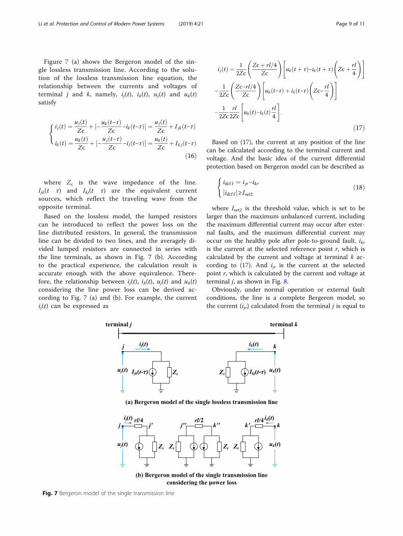
Figure 7 (a) shows the Bergeron model of the sin-gle lossless transmission line. According to the solu-tion of the lossless transmission line equation, therelationship between the currents and voltages ofterminal j and k, namely, ij(t), ik(t), uj(t) and uk(t)satisfy
(i jðtÞ ¼ ujðtÞ
Zcþ ½− ukðt−τÞ
Zc−ikðt−τÞ� ¼ ujðtÞ
Zcþ I jkðt−τÞ
ikðtÞ ¼ ukðtÞZc
þ ½− ujðt−τÞZc
−i jðt−τÞ� ¼ ukðtÞZc
þ Ik jðt−τÞð16Þ
where Zc is the wave impedance of the line.Ijk(t τ) and Ikj(t τ) are the equivalent currentsources, which reflect the traveling wave from theopposite terminal.
Based on the lossless model, the lumped resistorscan be introduced to reflect the power loss on theline distributed resistors. In general, the transmissionline can be divided to two lines, and the averagely di-vided lumped resistors are connected in series withthe line terminals, as shown in Fig. 7 (b). Accordingto the practical experience, the calculation result isaccurate enough with the above equivalence. There-fore, the relationship between ij(t), ik(t), uj(t) and uk(t)considering the line power loss can be derived ac-cording to Fig. 7 (a) and (b). For example, the currentij(t) can be expressed as
i jðtÞ ¼ 12Zc
Zcþ rl=4
Zc
!"ukðt þ τÞ−ikðt þ τÞ
Zcþ rl
4
!#
−1
2Zc
Zc−rl=4
Zc
!"ukðt−τÞ þ ikðt−τÞ
Zc−
rl4
!#
−1
2Zcrl2Zc
"ukðtÞ−ikðtÞ rl4
#:
ð17ÞBased on (17), the current at any position of the line
can be calculated according to the terminal current andvoltage. And the basic idea of the current differentialprotection based on Bergeron model can be described as(
idi f f ¼ i jr−ikr
jidi f f j≥ Iset2ð18Þ
where Iset2 is the threshold value, which is set to belarger than the maximum unbalanced current, includingthe maximum differential current may occur after exter-nal faults, and the maximum differential current mayoccur on the healthy pole after pole-to-ground fault. ikris the current at the selected reference point r, which iscalculated by the current and voltage at terminal k ac-cording to (17). And ijr is the current at the selectedpoint r, which is calculated by the current and voltage atterminal j, as shown in Fig. 8.Obviously, under normal operation or external fault
conditions, the line is a complete Bergeron model, sothe current (ijr) calculated from the terminal j is equal to
Fig. 7 Bergeron model of the single transmission line
Li et al. Protection and Control of Modern Power Systems (2019) 4:21 Page 9 of 11

the current (ikr) calculated from the terminal k. And idiffis equal to zero. Differently, if a fault occurs on the line,the line is divided to two Bergeron models by the faultpoint. So ijr is not equal to ikr anymore. It means idiff willnot be equal to zero anymore. In fact, according to thefurther analysis, after internal fault, the value of idiff ishighly related to the current (if) flowing to the faultpoint. In addition, it should be noted that, to eliminatethe coupling effect between the positive and negativepoles, the above calculated should be carried out afterbeing decoupled, and then the differential currents ofeach pole line can be obtained by inverse transformationfrom the mode variables.According to the above analysis, the Bergeron model
reflects the line distributed capacitor characteristic, sothe current differential protection based on Bergeronmodel can avoid the influence of the distributed capaci-tors completely, and the time delay in (15) can be can-celled, which means the acting speed is increasedsignificantly.However, the Bergeron model has fixed distributed
parameters, which does not consider the frequency-dependent characteristics of the line parameters. Aftera dc fault, the fault current and voltage contain vari-ous frequencies components. Therefore, the time-domain calculation based on the fixed line parameterswill lead to a non-negligible error [25]. To improvethe acting reliability of the protection, the improvedalgorithm, which can avoid the influence of the lineparameter frequency-dependent characteristic, needsto be researched.In addition, it should be pointed out that, for the
dc line protection in dc grid, the main and back-upconcept refers to the time aspect, not the spaceaspect. In fact, the pilot protections can also protectthe whole line. In some practical projects, the lineboundary elements may be absent, leading thesingle-ended protection to be ineffective. Under thiscondition, the pilot protections, which are not basedon the boundary characteristics, can be consideredas the main protection. Due to the communicationdelay, the acting speed of the pilot protection isslower than the single-ended protection. Therefore,the fault current limiting method with strongercurrent limiting capability must be configured for
the system, to limit the fault current fast increasingand reduce the requirement on the acting speed ofthe protection.
4 ConclusionsThe dc protection is the key technique for operation se-curity and power supply reliability of the multi-terminalVSC-HVDC grid. At present, different kinds of dc pro-tections have been researched.(1) The traveling-wave based protection (single-ended)
can still be used in the VSC-HVDC grid, due to the ex-istence of the dc reactor on both terminals of each line.However, its capability against high transition resistancestill needs to be improved.(2) The transient protection uses high-frequency com-
ponents of the voltage (or current) to identify the in-ternal and external faults, thus having stronger capabilityagainst high transition resistance. Moreover, its actingspeed is fast enough for VSC-HVDC grid, thus can beused as the main protection.(3) The directional pilot protection or current differen-
tial protection is suggested to be used as the back-upprotection for dc line in the multi-terminal VSC-HVDCgrid. However, for enough acting reliability, the im-proved schemes still need to be researched for both thedirectional pilot protection (traveling-wave based) andcurrent differential protection, to avoid the negative in-fluence of the transmission line parameter frequency-dependent characteristic.(4) Generally, in the multi-terminal VSC-HVDC grid,
the single-ended protection is suggested to be used asthe main protection, while the pilot protection to beused as the back-up one. Differently, under the condi-tion when the single-ended protection is ineffective, thepilot protections, which are not based on the boundarycharacteristics, can be considered as the main protec-tion. But the dc fault current limiting method withstronger limiting capability must be configured.
AcknowledgementsNot applicable.
Authors’ contributionsB. Li, as the first author, contributed significantly to analysis and research ofthe paper, J. W. He, as the corresponding author, contributed significantly tothe research, writing and submission of the paper. Y. Li and B. T. Li also
Fig. 8 The schematic diagram of the reference point
Li et al. Protection and Control of Modern Power Systems (2019) 4:21 Page 10 of 11

helped to improve the paper quality. All the authors read and approved thesubmitted manuscript.
Authors’ informationB. Li, J. W. He, Y. Li and B. T. Li are all with the School of Electrical andInformation Engineering, Tianjin University, Tianjin, China.
FundingThis work was supported by the National Natural Science Foundation ofChina (No. U1866205).
Availability of data and materialsNot applicable.
Competing interestsThe authors declare that they have no competing interests.
Received: 6 September 2019 Accepted: 10 October 2019
References1. Ooi, B. T., & Wang, X. (1991). Boost type PWM HVDC transmission system [J].
IEEE Transactions on Power Delivery, 6(4), 1557–1563.2. Flourentzou, N., Agelidis, V. G., & Demetriades, G. D. (2009). VSC-based HVDC
power transmission systems: An overview [J]. IEEE Trans Power Electron,24(3), 592–602.
3. Lesnicar, A., & Marquardt, R. (2003). An innovative modular multilevelconverter topology suitable for a wide power range [C]. Bologna, Italy: In IEEEPower Tech. Conf.
4. Rahman, M. H., Xu, L., & Yao, L. Z. (2016). Protection of large partitionedMTDC networks using DC-DC converters and circuit breakers [J]. Protectionand Control of Modern Power Systems, 1(2).
5. He, J. W., Li, B., & Li, Y. (2018). Analysis of the fault current limitingrequirement and design of the bridge-type FCL in the multi-terminal DCgrid [J]. IET Power Electron, 11(6), 968–976.
6. Yang, Y., Lin, Y., Xu, W., & Zuo, Z. M. (2017). Influence of Wudongde multi-terminal HVDC on security and stability of Guangdong power grid [J].Guangdong Electric Power, 30(11), 44–50.
7. Tang, G. F., Pang, H., He, Z. Y., & Wei, X. G. (2018). Research on keytechnology and equipment for Zhangbei 500kV DC grid [C]. In 2018international power electronics conference (pp. 2343–2351). Japan: Niigata.
8. Li, X. Q., Song, Q., Liu, W. H., Rao, H., et al. (2013). Protection ofnonpermanent faults on DC overhead lines in MMC-based HVDC systems[J]. IEEE Transactions on Power Delivery, 28(1), 483–490.
9. Li, B., He, J. W., Tian, J., et al. (2017). DC fault analysis for modular multilevelconverter-based system [J]. Journal of Modern Power Systems and CleanEnergy, 5(2), 275–282.
10. Marquardt, R. (2011). Modular multilevel converter topologies with DC-shortcircuit current limitation [C]. In 8th Int. Conf. Power Electron (pp. 1425–1431).ECCE Asia.
11. Zhang, J., & Zhao, C. (2015). The research of SM topology with DC faulttolerance in MMC-HVDC [J]. IEEE Transactions on Power Delivery, 30(3), 1561–1568.
12. Li, R., Fletcher, J. E., Xu, L., Holliday, D., & Williams, B. W. (2015). A hybridmodular multilevel converter with novel three-level cells for DC faultblocking capability [J]. IEEE Transactions on Power Delivery, 30(4), 2017–2026.
13. Hassanpoor, A., Hafner, J., & Jacobson, B. (2015). Technical assessment ofload commutation switch in hybrid HVDC breaker [J]. IEEE TransactionsPower Electronic, 30(10), 5393–5400.
14. Zheng, W., Zhang, N., & Yang, G. Y. (2015). Comparative and improvementinvestigation on the DC transmission line traveling wave protections ofSiemens and ABB [J]. Power System Protection and Control, 43(24), 149–154.
15. Descloux, J., Raison, B., & Curis, J.-B. (2014). Protection algorithm based ondifferential voltage measurement for MTDC grids [C]. In In 12th IETInternational Conference on Developments in Power System Protection (DPSP2014), Copenhagen, Denmark (pp. 1–5).
16. Li, R., Xu, L., & Yao, L. Z. (2017). DC fault detection and location in meshedmultiterminal HVDC systems based on DC reactor voltage change rate [J].IEEE Transactions on Power Delivery, 32(3), 1516–1526.
17. Leterme, W., Beerten, J., & Hertem, D. V. (2016). Nonunit protection of HVDCgrids with inductive DC cable termination [J]. IEEE Transactions on PowerDelivery, 31(2), 820–828.
18. Li, B., Li, Y., He, J. W., & Wen, W. J. A novel single-ended transient-voltage-based protection strategy for flexible DC grid [J]. IEEE Transactions on PowerDelivery. Early Access. https://doi.org/10.1109/TPWRD.2019.2910390.
19. Liu, J., Tai, N. L., & Fan, C. J. (2017). Transient-voltage-based protectionscheme for DC line faults in the multiterminal VSC-HVDC system [J]. IEEETransactions on Power Delivery, 32(3), 1483–1494.
20. Xiang, W., Yang, S. Z., Xu, L., et al. (2019). A transient voltage-based DC faultline protection scheme for MMC-based DC grid embedding DC breakers [J].IEEE Transactions on Power Delivery, 34(1), 334–345.
21. Epameinondas Kontos, Rodrigo Teixeira Pinto, Pavol Bauer. (2013). Controland protection of VSC-based multi-terminal DC networks [N]. LAP LAMBERTAcademic Publishing, ISBN: 978-3659486630.
22. Li, Z., Zou, G. B., Tong, B. B., et al. (2015). Novel traveling wave protectionmethod for high voltage DC transmission line [C] (pp. 1–5). Denver, USA: InIEEE Power &Energy Society General Meeting.
23. Zhou, H. Y., Yu, J., Huang, J. Y., et al. (2008). Issues over DC line differentialprotection [J]. Southern Power System Technology, 2(3), 17–21.
24. Li, B., Chang, W. H., He, J. L., & Bo, Z. Q. (2009). Special problems in currentdifferential protection based on Bergeron model [C] (pp. 1–4). Wuhan, China:Asia-Pacific Power and Energy Engineering Conference.
25. Song, G. B., Cai, X. L., Gao, S. P., et al. (2011). Novel current differentialprotection principle of VSC-HVDC considering frequency-dependentcharacteristic of cable line [J]. Proceedings of the CSEE, 31(22), 105–111.
Li et al. Protection and Control of Modern Power Systems (2019) 4:21 Page 11 of 11