A Review of High Thrust, High Delta-V Options for
14
A Review of High Thrust, High Delta-V Options for Microsatellite Missions David B. Scharfe * ERC Incorporated, Edwards AFB, CA, 93524 Andrew D. Ketsdever † Air Force Research Laboratory, Edwards AFB, CA, 93524 Microsatellites have been suggested as a means of enhancing a variety of proposed space missions, ranging from low Earth orbit to Solar System exploration. With improvements in propulsion technology geared toward microsatellites, the ultimate delta-V (ΔV ) capabilities of some microsatellite systems are now in the range of several km/s, opening the doors to a variety of high ΔV , fast response scenarios. This paper provides a brief overview of propulsion technologies currently available for microsatellites, and an evaluation of each technology for potential use in a demanding mission. The sample mission is that of a microsatellite inspector which, starting in a 200 km parking orbit, must be diverted to rendezvous with another satellite in orbit at a different altitude and inclination. It is found that existing bipropellant microrocket designs provide a high thrust value, combined with a 300 s specific impulse, allowing for response times of only a few hours for such an inspector mission with ΔV requirements over 1 km/s. Miniaturized electrostatic thrusters provide the largest ultimate ΔV capability, approaching 10 km/s, but with a very low thrust level and therefore a response time capability of several months. Newly developed micro-solar thermal systems fill in the middle ground of these two options, providing the moderate thrust levels and specific impulse values necessary for a response time on the order of one day and a ΔV of several km/s. I. Introduction L ight-weight (100 kg class and smaller) microsatellites, combined with miniaturized spacecraft compo- nents, are a well-established technology proven to reduce the costs and enhance the capabilities of certain space missions. Though the capabilities of microsatellites are traditionally more limited than those of their larger counterparts, the relatively small mass of microsatellites could allow for drastically reduced launch costs; reduced development times for microsatellites may also result in the use of more modern technology, which can enhance capabilities and mitigate some of the compromises made to reduce system mass. 1 Ad- ditionally, the concept of producing several similar or identical microsatellites provides another avenue for targeting the needs of specific missions; such a group of microsatellites could be flown in a cluster to replace a single large satellite, or flown separately to perform various aspects of a mission requiring presence at mul- tiple locations or at various times. Further, if a satellite were to become damaged while in orbit, replacing a single microsatellite is fairly trivial when compared to replacing an entire, traditionally-sized satellite: a single, smaller satellite can be constructed and launched on shorter notice, and likely with decreased expense, when compared to the process required for a full-sized satellite. The above-listed advantages of microsatellite missions are well known, but as yet, microsatellite capa- bilities in terms of the ultimate velocity increment (ΔV ) available for station keeping, orbit transfers, and other maneuvers have been viewed as somewhat limited. However, newer technologies, by way of advanced micro-chemical and micro-electric propulsion systems, present the opportunity to remove that limitation, * Staff Scientist, Advanced Propulsion Concepts, 10 E. Saturn Blvd., Edwards AFB, CA 93524, AIAA Member. † Program Manager, Advanced Propulsion Concepts, 10 E. Saturn Blvd., Edwards AFB, CA 93524, AIAA Assoc. Fellow. 1 of 14 American Institute of Aeronautics and Astronautics Distribution A: Approved for public release; unlimited distribution. 45th AIAA/ASME/SAE/ASEE Joint Propulsion Conference & Exhibit 2 - 5 August 2009, Denver, Colorado AIAA 2009-4824 This material is declared a work of the U.S. Government and is not subject to copyright protection in the United States.
Transcript of A Review of High Thrust, High Delta-V Options for

A Review of High Thrust, High Delta-V Options for
Microsatellite Missions
David B. Scharfe∗
ERC Incorporated, Edwards AFB, CA, 93524
Andrew D. Ketsdever†
Air Force Research Laboratory, Edwards AFB, CA, 93524
Microsatellites have been suggested as a means of enhancing a variety of proposed spacemissions, ranging from low Earth orbit to Solar System exploration. With improvements inpropulsion technology geared toward microsatellites, the ultimate delta-V (∆V ) capabilitiesof some microsatellite systems are now in the range of several km/s, opening the doorsto a variety of high ∆V , fast response scenarios. This paper provides a brief overview ofpropulsion technologies currently available for microsatellites, and an evaluation of eachtechnology for potential use in a demanding mission. The sample mission is that of amicrosatellite inspector which, starting in a 200 km parking orbit, must be diverted torendezvous with another satellite in orbit at a different altitude and inclination. It is foundthat existing bipropellant microrocket designs provide a high thrust value, combined with a300 s specific impulse, allowing for response times of only a few hours for such an inspectormission with ∆V requirements over 1 km/s. Miniaturized electrostatic thrusters providethe largest ultimate ∆V capability, approaching 10 km/s, but with a very low thrust leveland therefore a response time capability of several months. Newly developed micro-solarthermal systems fill in the middle ground of these two options, providing the moderatethrust levels and specific impulse values necessary for a response time on the order of oneday and a ∆V of several km/s.
I. Introduction
Light-weight (100 kg class and smaller) microsatellites, combined with miniaturized spacecraft compo-nents, are a well-established technology proven to reduce the costs and enhance the capabilities of certain
space missions. Though the capabilities of microsatellites are traditionally more limited than those of theirlarger counterparts, the relatively small mass of microsatellites could allow for drastically reduced launchcosts; reduced development times for microsatellites may also result in the use of more modern technology,which can enhance capabilities and mitigate some of the compromises made to reduce system mass.1 Ad-ditionally, the concept of producing several similar or identical microsatellites provides another avenue fortargeting the needs of specific missions; such a group of microsatellites could be flown in a cluster to replacea single large satellite, or flown separately to perform various aspects of a mission requiring presence at mul-tiple locations or at various times. Further, if a satellite were to become damaged while in orbit, replacinga single microsatellite is fairly trivial when compared to replacing an entire, traditionally-sized satellite: asingle, smaller satellite can be constructed and launched on shorter notice, and likely with decreased expense,when compared to the process required for a full-sized satellite.
The above-listed advantages of microsatellite missions are well known, but as yet, microsatellite capa-bilities in terms of the ultimate velocity increment (∆V ) available for station keeping, orbit transfers, andother maneuvers have been viewed as somewhat limited. However, newer technologies, by way of advancedmicro-chemical and micro-electric propulsion systems, present the opportunity to remove that limitation,
∗Staff Scientist, Advanced Propulsion Concepts, 10 E. Saturn Blvd., Edwards AFB, CA 93524, AIAA Member.†Program Manager, Advanced Propulsion Concepts, 10 E. Saturn Blvd., Edwards AFB, CA 93524, AIAA Assoc. Fellow.
1 of 14
American Institute of Aeronautics and AstronauticsDistribution A: Approved for public release; unlimited distribution.
45th AIAA/ASME/SAE/ASEE Joint Propulsion Conference & Exhibit2 - 5 August 2009, Denver, Colorado
AIAA 2009-4824
This material is declared a work of the U.S. Government and is not subject to copyright protection in the United States.
0 5 10 150
500
1000
1500
2000
Inclination Change, degreesR
equi
red
Vel
ocity
Incr
emen
t, m
/s
(b)
200 km500 km1000 km2000 km4000 km
0 2000 40000
500
1000
1500
2000
Altitude Change, km, from 200 km orbit
Req
uire
d V
eloc
ity In
crem
ent,
m/s
(a)
Figure 1. (A): Required velocity increment to alter the altitude of the initial 200 km circular orbit. A Hohmanntransfer is assumed. (B): ∆V required for inclination change at various altitudes.
providing a combination of high thrust, high specific impulse, and high propellant throughput suitable fortotal velocity changes on the order of kilometers per second. Proposed microsatellite missions now includetransfers from low Earth orbit (LEO) to geostationary orbit (GEO), transfers to lunar orbits, and eventransfers beyond Earth orbit to explore other planets and various near-Earth objects (NEO’s).2–12
It is the goal of this paper, therefore, to explore the feasibility of various technologies for achieving thegoals of a novel, high-∆V , fast-response mission using microsatellite technology. The proposed mission isthat of a microsatellite inspector that can, on short notice, be diverted from its orbit to rendezvous withanother satellite. The purpose of this rendezvous may range from a simple close-range optical inspection oranalysis of the destination satellite, to physical contact for purposes of increasing the target satellite’s missionlife via maintenance, refueling, or other such operations.11,13 Although many such inspector satellites couldpotentially be launched into varying initial orbits to yield flexibility and redundancy, and to limit the ∆Vrequirements on any one inspection mission, ∆V requirements are expected to be on the order of 1 km/s.In the interest of response time, thrust requirements will be placed at 10 mN or higher, though thrust levelsover 1 N are ideal to ensure that required orbit alterations can be achieved in under one day.
II. Generalized Calculations
A microsatellite inspector, like that described above, would require a significant velocity increment toachieve the inclination change and altitude alteration necessary to rendezvous with another satellite (orseveral other satellites) in LEO. Additional ∆V requirements for slight rephasing of the orbit, or for aprecise rendezvous with a target satellite, are neglected in this analysis.
Assuming an initial circular orbit at an altitude of 200 km, the ∆V required to alter the orbit altitudeto various degrees (via Hohmann transfer) is illustrated in the plot provided in Figure 1(a). Limiting themicrosatellite to a maximum velocity increment of 1.5 km/s, an increase in altitude of 3500 km (to a 3700 kmorbit altitude) could potentially be achieved.
Likewise, the ∆V ’s required for various levels of inclination change at the altitudes the microsatellite mightachieve are illustrated in Figure 1(b). Again limiting the microsatellite to a maximum velocity increment of
2 of 14
American Institute of Aeronautics and AstronauticsDistribution A: Approved for public release; unlimited distribution.

0 500 1000 15000
20
40
60
80
100
Velocity Increment, m/sP
rope
llant
Mas
s, k
g
(b)
Isp
= 50 s
Isp
= 100 s
Isp
= 200 s
Isp
= 500 s
Isp
= 1500 s
0 2000 4000 60000
5
10
15
20
5001000
1500
1500
2000
2000
2500
2500
2500
3000
3000
3500
3500
4000
Altitude Change, km, from 200 km orbit
Incl
inat
ion
Cha
nge,
deg
rees
(a)
Figure 2. (A): Color map and contours indicating the required ∆V values required to achieve a given combinationof altitude increase and inclination change. Units of the ∆V are m/s. (B): Required propellant mass for a 100 kgmicrosatellite to achieve a desired velocity increment utilizing thrusters with various Isp values.
1.5 km/s, and keeping the altitude at 200 km, an inclination change of 11◦ is possible.Combining the calculations used to produce the plots in Figure 1, and assuming the inclination change is
performed after circularizing the orbit at the higher altitude, Figure 2(a) was produced. Combined altitudeand inclination changes could be optimized to reduce the total ∆V required, but performing the calculationin the manner described will provide an upper limit to the total required velocity increment, and allow forsmaller, less certain, ∆V components such as minor orbit rephasing, attitude control, and precise rendezvousapproach. Again limiting the craft to a total ∆V of 1.5 km/s, one can, for example, estimate that raisingthe orbit altitude to 2000 km (an 1800 km increase in altitude) requires 880 m/s ∆V , allowing for just over5◦ of inclination change to the final orbit.
The required propellant mass for a 100 kg microsatellite, as a function of desired ∆V and thruster Isp,is illustrated in Figure 2(b); calculations were performed using the idealized rocket equation. Whereas ahigher Isp thruster requires less propellant, it would also generally require an electric propulsion system witha larger power supply and solar array, impinging on some (or all) of the mass benefit associated with reducedpropellant consumption. Note also that in such systems, a higher specific impulse typically indicates reducedthrust, which will affect the transfer time capabilities of the microsatellite. Nonetheless, with any of theIsp ranges indicated in the plot, and achieved by various miniaturized thruster technologies, a microsatellitewith a 1.5 km/s (or greater) ∆V capability is technically feasible. However, if a propellant fraction of 80%or less is required to allow for a useful payload capacity, then only those systems with Isp values in excess of100 s will likely be suitable for the proposed mission.
III. Microsatellite Propulsion Technologies
A previous, exhaustive review of microsatellite propulsion technologies was completed by Mueller adecade ago.14,15 In the discussion to follow, we seek to survey the more recent developments in the field,while focusing on the high thrust and high ∆V needs of a rendezvous mission.
Multiple microsatellite propulsion technologies that may be suitable or adaptable to a satellite-rendezvousmission have been described recently in the literature. These technologies range from arrays of solid-
3 of 14
American Institute of Aeronautics and AstronauticsDistribution A: Approved for public release; unlimited distribution.

Table 1. Summary of propulsion technologies available for microsatellites. Data has been omitted where it is unavailablein the literature (spaces left blank) or is effectively irrelevant (marked with –). Note that some systems such as solarthermal and electric rockets require additional mass for power systems, which is not included in the thruster mass.
Thruster Type References Thrust Isp [s] Power [W] Thruster Mass
Hall/Ion 11,22–24,26–34 0.4–20 mN 300–3700 14-300 ≤ 1 kgFEEP/colloid 11,25,26 0.1 µN–1.5 mN 450–9000 1-100 0.1–1 kg
Electromagnetic 11,22,26,35 0.03–2 mN 200-4000 ≤ 10 0.06–0.5 kgElectrothermal 6,11,26,36–39 ≤ 220 mN 50–250 3–300 0.1–1 kg
Cold Gas 16,26,40 0.5 mN–3 N 40–80 – 0.01–1 kgMonopropellant 4,11,25,26,41–43 1 µN–1.5 N 100-230 ≤ 6 0.01–0.5 kg
Bipropellant 4,6, 11,16,19,25,26,44 1 µN–45 N 100-320 ≤ 6 0.01–0.5 kgDecomposing Solid 45 230
Laser Micro. (ablation) 18 1 µN 100–300 2Laser Micro. (ignition) 18 1–10 mN 37–100 –
Laser Plasma 3,46 0.1–1 mN 500–1000 2 ≤ 1 kgHollow Cathode 47 1 µN–10 mN 50–1200 5–1000Solar Thermal 4,8, 9, 20,48–50 56 mN – 1 N 200–1100 – ≤ 10 kg
propellant digital microthrusters16–18 through bipropellant microrockets with 10’s of newtons of thrust andIsp values over 300 s.19 Non-chemical technologies include solar thermal propulsion mechanisms offeringseveral hundred seconds of Isp while producing newtons of thrust,9,10,20 and electric propulsion technologiesfor microsatellites that offer low thrust but up to several thousand second specific impulse values.7,21–25
A partial survey of existing microsatellite propulsion technologies was completed by Stein, et al. in2008.26 An updated and augmented version of this compilation, including specifications of more advancedand higher-thrust miniaturized designs, is provided in Table 1.
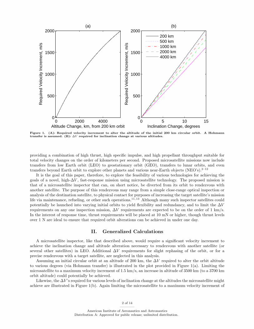
When analyzing the details of Table 1, it is important to note that the specifications indicate traits ofindividual thrusters, whereas many of the technologies listed lend themselves well to satellite designs withmultiple identical thrusters working in unison. Small-size, low-power thrusters are ideal for this type ofoperation, and a microsatellite designed with multiple small propulsive units of any of the types listed inTable 1 (except perhaps the higher-powered electric rockets) can be imagined. This is a common assumption,for example, in the design of microelectromechanical (MEMS) based bipropellant chips.6,16,19 This strategyof design lends itself to an enhancement over the performance (thrust) of a single thruster, and also yieldsincreased redundancy (and therefore reliability) relative to a single, larger thruster. As an example of sucha configuration, a clear illustration of this concept is provided by Marcu, et al.,19 and it is reproduced hereas Figure 3.
Table 2. Propellant mass fraction required to achieve a 1.5 km/s velocity increment using select microthruster tech-nologies. The Isp values assumed for each technology are typical, selected from within the ranges provided in Table1.
Thruster Type Assumed Isp [s] Propellant Fraction [%]
Bipropellant 320 38Monopropellant 230 49
Cold Gas 60 92Solar Thermal (H2) 1000 14
Solar Thermal (NH3) 400 32Electrothermal 100 78
Electrostatic (Hall) 1000 14Electrostatic (Ion) 3000 5
4 of 14
American Institute of Aeronautics and AstronauticsDistribution A: Approved for public release; unlimited distribution.
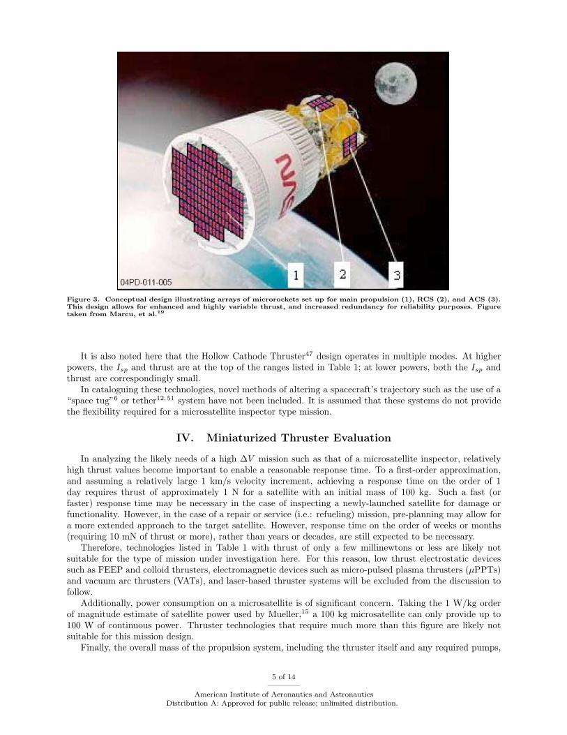
Figure 3. Conceptual design illustrating arrays of microrockets set up for main propulsion (1), RCS (2), and ACS (3).This design allows for enhanced and highly variable thrust, and increased redundancy for reliability purposes. Figuretaken from Marcu, et al.19
It is also noted here that the Hollow Cathode Thruster47 design operates in multiple modes. At higherpowers, the Isp and thrust are at the top of the ranges listed in Table 1; at lower powers, both the Isp andthrust are correspondingly small.
In cataloguing these technologies, novel methods of altering a spacecraft’s trajectory such as the use of a“space tug”6 or tether12,51 system have not been included. It is assumed that these systems do not providethe flexibility required for a microsatellite inspector type mission.
IV. Miniaturized Thruster Evaluation
In analyzing the likely needs of a high ∆V mission such as that of a microsatellite inspector, relativelyhigh thrust values become important to enable a reasonable response time. To a first-order approximation,and assuming a relatively large 1 km/s velocity increment, achieving a response time on the order of 1day requires thrust of approximately 1 N for a satellite with an initial mass of 100 kg. Such a fast (orfaster) response time may be necessary in the case of inspecting a newly-launched satellite for damage orfunctionality. However, in the case of a repair or service (i.e.: refueling) mission, pre-planning may allow fora more extended approach to the target satellite. However, response time on the order of weeks or months(requiring 10 mN of thrust or more), rather than years or decades, are still expected to be necessary.
Therefore, technologies listed in Table 1 with thrust of only a few millinewtons or less are likely notsuitable for the type of mission under investigation here. For this reason, low thrust electrostatic devicessuch as FEEP and colloid thrusters, electromagnetic devices such as micro-pulsed plasma thrusters (µPPTs)and vacuum arc thrusters (VATs), and laser-based thruster systems will be excluded from the discussion tofollow.
Additionally, power consumption on a microsatellite is of significant concern. Taking the 1 W/kg orderof magnitude estimate of satellite power used by Mueller,15 a 100 kg microsatellite can only provide up to100 W of continuous power. Thruster technologies that require much more than this figure are likely notsuitable for this mission design.
Finally, the overall mass of the propulsion system, including the thruster itself and any required pumps,
5 of 14
American Institute of Aeronautics and AstronauticsDistribution A: Approved for public release; unlimited distribution.

power systems, high-pressure tanks, or other such components, is of crucial concern for a mass-limitedmicrosatellite. With a high-Isp thruster that can achieve a large ∆V using relatively little propellant, asystem weighing up to several kilograms may be acceptable; for a system requiring more propellant toachieve the same ∆V , the system mass will be more critical to allow for the extra required propellant mass.To illustrate the necessity of this trade-off, the propellant mass fractions required for select microsatellitethruster technologies to achieve a 1.5 km/s ∆V are listed in Table 2. Note, for example, that achieving a1.5 km/s change in velocity with a cold gas jet may require over 92 kg of propellant on a 100 kg microsatellite.
Based on the evaluation metrics discussed above, the miniaturized thruster technologies with the mostpotential utility in a microsatellite inspector type mission are: Bipropellant, Monopropellant, Cold Gas,Solar Thermal, Electrothermal, and Electrostatic (Hall/Ion) thrusters. These technologies will be furtherexplored below. It is noted here that while the term “microthruster” is often used to denote a thruster whichproduces thrust in the sub-millinewton range, the thrusters under consideration here are notable for theirsmall size and power consumption, but are intended to produce large enough thrust to impart a significantvelocity increment to the microsatellite in a short amount of time.
IV.A. Bipropellant Microrockets
Figure 4. (A): Design of a 3–10 lb thrust MEMS bipropellant rocket. (B): Photograph of MEMS-fabricated bipropellantrocket nozzle; plumbing and cooling detail is evident. Figures taken from Marcu, et al.19
Bipropellant microrockets are advanced MEMS devices, effectively integrating the necessary valves,pumps, combustion chamber, and nozzle onto a single microfabricated chip or assembly. Perhaps the mostnotable of the present options available in the literature is the design proposed by Marcu, et al.,19 which isestimated to produce up to 10 lb (45 N) of thrust per chip at an Isp of 300 s. The thrust-to-weight ratioof the chip is roughly 1000:1, indicating that the thruster mass, including turbopumps, valves, sensors, thecombustion chamber, and the nozzle, weighs in at well under 100 grams. Further, the use of the turbopumpsto pressurize the fuel is suggested as a means to save system mass by eliminating the need for a high-pressurepropellant storage tank.25 Each microrocket chip is fabricated from several layers of silicon and has a totalvolume of less than 2 cm3. This thruster design is illustrated in Figure 4.
The cost per newton of thrust for a chip-based propulsion system is expected to be a factor of 5–10 lessthan that of a traditional upper stage bipropellant engine.19 These chip-based engines consume very littlepower, and can be operated in clusters (see Figure 3) to enhance mission flexibility and reliability. Individualchips can still be throttled to vary thrust, and differing numbers of chips can be operated to further vary thethrust output. The chip-based bipropellant engines can still operate at hundreds of atmospheres of internalpressure with Isp values similar to those of their full-scale counterparts, so the performance penalty relativeto full-sized conventional rockets is believed to be minimal.
Other, similar miniaturized bipropellant thruster technologies have been presented,4,6, 11,16,25 all pro-viding roughly 300 s of Isp with thrust levels well above 1 N, and consuming only a few watts of power.
6 of 14
American Institute of Aeronautics and AstronauticsDistribution A: Approved for public release; unlimited distribution.

While much smaller bipropellant engines have also been designed, offering millinewtons of thrust,11,44 largeefficiency losses due to heat loss and resistance to the flow are likely to occur in these very small bipropellantengines (i.e.: true microthrusters producing millinewtons or micronewtons of thrust). No such losses seem tobe apparent at thrust levels greater than 1 N; the exhaust velocity (Isp) of these MEMS microrockets shouldbe equivalent to that of a full-sized thruster operating with the same propellants and combustion cycle.19
With multi-newton thrust values available to a microsatellite, fast response time for even a large ∆V isquite feasible. At 45 N of thrust, a ∆V of 1 km/s could be achieved in well under an hour for a 100 kgmicrosatellite. Clustering of several of these MEMS microrockets can be used to further enhance the thrustand response time, possibly achieving the thrust level required to approximate an instantaneous ∆V for aHohmann-type orbit transfer.
Additionally, as can be seen via Figure 2(b), with an Isp value of 300 s, well under 50 kg of propellantwould be required to provide a 1.5 km/s ∆V , leaving enough mass budget on board the microsatellite forpurposes such as payload mass or other satellite subsystems.
IV.B. Monopropellant Microrockets
Figure 5. (A): Laboratory model of a monopropellant thruster. (B): Cross section thereof showing the internal assemblywith the catalyst. Figures taken from Scharlemann, et al.25
Miniaturized monopropellant rockets, like that illustrated in Figure 5, are very similar to their bipropel-lant counterparts, but with a simpler design due to the need for only a single propellant feed. Monopropellantdesigns also generally require a catalyst bed to ignite the propellant,11,25,41–43 which is typically hydrazineor hydrogen peroxide. Additionally, the development of monopropellant designs for main propulsion systemson microsatellites benefits from the wide-scale use of small hydrazine thrusters for attitude control on largersatellites.41
As with the bipropellant engines, the propellant can be stored in a pressurized tank (with the thrusteroperating in blowdown mode), or a miniaturized turbopump could be used to pressurize the fuel. Addition-ally, much like the bipropellant engines discussed above, small monopropellant thrusters are compact enoughand consume little power so that they can be clustered to increase thrust, redundancy, and flexibility.
The miniaturized monopropellant thrusters catalogued in Table 1 have maximum thrust values only onthe order of 1 N,11,25,41–43 which is notably lower than the bipropellant thrusters. However, this deficiencyis likely non-technological and merely an artifact of individual engineering goals or mission requirements.Many of the proposed thrusters are, in fact, intended for use on nanosatellites 10 kg or smaller. In many
7 of 14
American Institute of Aeronautics and AstronauticsDistribution A: Approved for public release; unlimited distribution.

cases, MEMS fabricated chemical propulsion systems are being developed due to the effective miniaturizationof thruster designs using this technique.43 Combustion research plays a critical role in the success of thesemicroscale thrusters with researchers attempting to design efficient, high temperature chemical propulsionsystems.52 The effects of miniaturization on the fluid mechanics, heat transfer, and combustion characteris-tics involved in micro-chemical devices will act to limit the efficiency of these systems. Research is requiredto investigate the effects of viscous boundary layers, microscale heat transfer, and large species gradients inorder to improve the performance of micro-chemical propulsion systems.
A monopropellant microrocket would be simpler than a bipropellant system, requiring only a single fuelpump and one propellant tank. Whereas the monopropellant systems have notably lower Isp values (230 svs. 300 s for bipropellant engines), the simplicity and potential mass savings of such a system (only onepropellant tank, etc. required) may outweigh this performance deficit. A propellant mass of 50 kg could stillprovide 1.5 km/s of ∆V , allowing for a highly capable microsatellite. However, some researchers have runinto lifetime issues with the catalyst bed required to ignite the monopropellant, noting a decrease in reactivityafter several kilograms of propellant throughput;42 this issue should be overcome via design optimizations.
IV.C. Miniature Cold Gas Thrusters
Figure 6. (A): 80 g Moog model 50X802 gas regulator assembly. (B): 3.5 N thrust, 22 g Moog model 58-118 SAFERthruster, including internal valves. Figures taken from Bzibziak.40
Recent work in cold gas thrusters suitable for microsatellites, especially that by Moog Inc.,40 has shownthrust levels of several newtons from thrusters weighing only a few grams. As an entire assembly, includingminiaturized pressure regulators, valves, and thruster nozzles, but neglecting the high-pressure propellanttank, the system mass would be under 1 kg. All components have been designed to operate with highpressures and very low leak rates. Samples of these miniaturized components are illustrated in Figure 6.
Whereas the thrust level of such a cold gas microthruster is suitable for a relatively fast response, the Isp
value of a cold gas thruster is generally only 40-80 s, which significantly hampers the performance. Achievinga 1.5 km/s ∆V with such a cold gas thruster would require a propellant mass fraction of over 80%, leavinglittle mass budget available for other purposes.
It is noteworthy, however, that these thrusters from Moog Inc.40 were tested running nitrogen and xenonas the propellant gas; switching to a lighter propellant (such as hydrogen) would significantly increase theexhaust velocity (Isp), but would also likely increase the mass of the tank required to store the propellant.With a similar volume flow rate, a lighter propellant gas would also result in decreased thrust.
IV.D. Solar Thermal Thrusters
Solar thermal thrusters, which concentrate solar rays to heat a compressed gas propellant, offer a step up fromcold gas microthrusters. Whereas such designs require additional mass in the form of solar collectors, theIsp can reach over 1000 s, with up to 1 N of thrust, operating on hydrogen propellant;4,9 heavier propellantssuch as ammonia can still produce Isp values of 300–400 s,4,8, 9, 20,50 rivaling the capabilities of bipropellantengines in a very robust system. Two configurations, utilizing fiber optic lines to direct the collected solar
8 of 14
American Institute of Aeronautics and AstronauticsDistribution A: Approved for public release; unlimited distribution.
Figure 7. Basic schematics of fiber-coupled solar thermal propulsion systems. (A): On-axis solar collection. (B):Off-axis collection. Figures taken from Nakamura, et al.9
flux, are illustrated in Figure 7; the solar flux can also be reflected directly onto the propellant heatingchamber.
Whereas it may seem that a solar thermal propulsion system would have strict limitations due to times ofeclipse or strict thrust-vector pointing requirements based on the orientation of sun, this is not necessarily thecase. Solar thermal systems have been designed with thermal storage capabilities, allowing for augmentedthrust (beyond that of a cold gas jet) in times of eclipse.49,50 Further, thrust-vector pointing relative toincoming sunlight can be varied by changing the orientation of solar concentrator arrays; additional flexibilityin this regard can be offered via fiber optic cables used to pass sunlight from the concentrator focal point tothe propellant heating cavity.8,9, 49,50
The mass of the collection system can be fairly large, possibly requiring several square meters of solarconcentrator and a significant mass of fiber optic cables to carry the equivalent intensity of several thousandsuns.9 A system mass of over 20 kg to achieve 1 N of thrust and 1000 s of Isp on hydrogen is a possibility, butswitching to (heavier) ammonia propellant at a similar thrust level and 400 s Isp would significantly decreasethe mass of the solar thermal propulsion system to roughly 7 kg, excluding the propellant.9 Additionally,this system design assumes several kilograms of fiber optic lines and couplings; reflecting sunlight directlyonto the propellant heating zone could eliminate this mass, albeit at the cost of some system flexibility.
Even with a 20 kg solar thermal system, however, at an Isp of 1000 s, only 20 kg of propellant would berequired to achieve a 1.5 km/s ∆V , resulting in an entire propulsion system, including propellant, with amass less than 50% that of a highly-capable microsatellite. With a 7–8 kg ammonia system with a 300–400 sIsp, 40–50 kg of propellant would be required for such a ∆V , resulting in a similar fraction of the satellitemass being taken up by the propulsion system. At 1 N of thrust, this ∆V would be achievable in under oneday, providing a reasonable response time for a microsatellite inspector or rendezvous type mission.
IV.E. Electrothermal Microthrusters
Electrothermal rockets, such as arcjets and resistojets, utilize electric power to heat a propellant gas. Formicrosatellite purposes, the amount of power that can be supplied (and therefore the maximum optimal gasflow rate) is limited by the power bus of the satellite; for a 100 kg satellite, this limit is likely around 100 Wof continuous power.15
Small resistojets, like that illustrated in Figure 8, have been shown to operate on a wide variety ofpropellants, including ammonia, butane, hydrogen, nitrogen, and noble gases.38 In the microsatellite powerrange, small resistojets producing up to 220 mN of thrust operating on up to 80 W of augmenting power havebeen demonstrated.11 Two examples include a 13.7 W resistojet operating on butane propellant to produce100 mN of thrust at 100 s of Isp
11,38 and an 80 W resistojet with xenon propellant producing 220 mN ofthrust at an Isp of 50 s.11 Both of these devices weigh approximately 200 g.11
A typical resistojet, by increasing the temperature of the gas by several hundred kelvin, provides up to a70% increase in the Isp value relative to a cold gas jet.38 Even in that case, however, the Isp value is still ina relatively inefficient range for producing large ∆V values in a microsatellite. For example, Gibbon, et al.
9 of 14
American Institute of Aeronautics and AstronauticsDistribution A: Approved for public release; unlimited distribution.
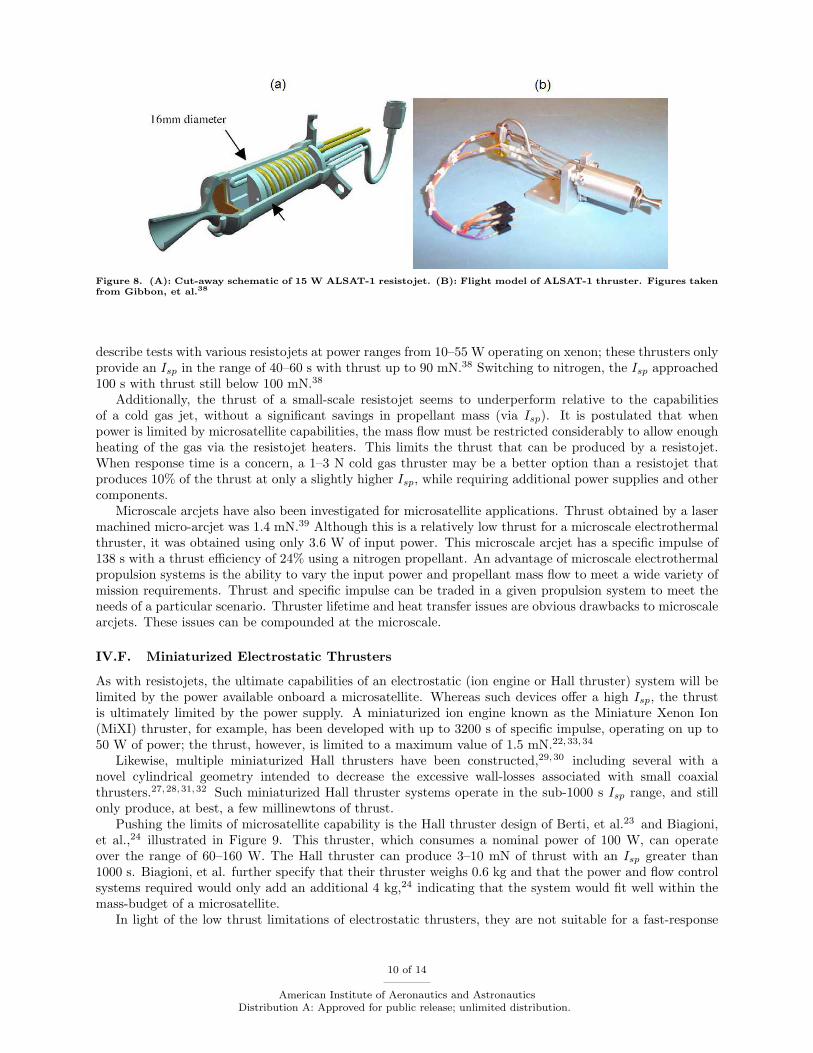
Figure 8. (A): Cut-away schematic of 15 W ALSAT-1 resistojet. (B): Flight model of ALSAT-1 thruster. Figures takenfrom Gibbon, et al.38
describe tests with various resistojets at power ranges from 10–55 W operating on xenon; these thrusters onlyprovide an Isp in the range of 40–60 s with thrust up to 90 mN.38 Switching to nitrogen, the Isp approached100 s with thrust still below 100 mN.38
Additionally, the thrust of a small-scale resistojet seems to underperform relative to the capabilitiesof a cold gas jet, without a significant savings in propellant mass (via Isp). It is postulated that whenpower is limited by microsatellite capabilities, the mass flow must be restricted considerably to allow enoughheating of the gas via the resistojet heaters. This limits the thrust that can be produced by a resistojet.When response time is a concern, a 1–3 N cold gas thruster may be a better option than a resistojet thatproduces 10% of the thrust at only a slightly higher Isp, while requiring additional power supplies and othercomponents.
Microscale arcjets have also been investigated for microsatellite applications. Thrust obtained by a lasermachined micro-arcjet was 1.4 mN.39 Although this is a relatively low thrust for a microscale electrothermalthruster, it was obtained using only 3.6 W of input power. This microscale arcjet has a specific impulse of138 s with a thrust efficiency of 24% using a nitrogen propellant. An advantage of microscale electrothermalpropulsion systems is the ability to vary the input power and propellant mass flow to meet a wide variety ofmission requirements. Thrust and specific impulse can be traded in a given propulsion system to meet theneeds of a particular scenario. Thruster lifetime and heat transfer issues are obvious drawbacks to microscalearcjets. These issues can be compounded at the microscale.
IV.F. Miniaturized Electrostatic Thrusters
As with resistojets, the ultimate capabilities of an electrostatic (ion engine or Hall thruster) system will belimited by the power available onboard a microsatellite. Whereas such devices offer a high Isp, the thrustis ultimately limited by the power supply. A miniaturized ion engine known as the Miniature Xenon Ion(MiXI) thruster, for example, has been developed with up to 3200 s of specific impulse, operating on up to50 W of power; the thrust, however, is limited to a maximum value of 1.5 mN.22,33,34
Likewise, multiple miniaturized Hall thrusters have been constructed,29,30 including several with anovel cylindrical geometry intended to decrease the excessive wall-losses associated with small coaxialthrusters.27,28,31,32 Such miniaturized Hall thruster systems operate in the sub-1000 s Isp range, and stillonly produce, at best, a few millinewtons of thrust.
Pushing the limits of microsatellite capability is the Hall thruster design of Berti, et al.23 and Biagioni,et al.,24 illustrated in Figure 9. This thruster, which consumes a nominal power of 100 W, can operateover the range of 60–160 W. The Hall thruster can produce 3–10 mN of thrust with an Isp greater than1000 s. Biagioni, et al. further specify that their thruster weighs 0.6 kg and that the power and flow controlsystems required would only add an additional 4 kg,24 indicating that the system would fit well within themass-budget of a microsatellite.
In light of the low thrust limitations of electrostatic thrusters, they are not suitable for a fast-response
10 of 14
American Institute of Aeronautics and AstronauticsDistribution A: Approved for public release; unlimited distribution.

Figure 9. 100 W miniaturized Hall thruster designed to operate at 100 W nominal power, producing up to 10 mN ofthrust with a maximum Isp of 1000 s.23,24 Figure taken from Berti, et al.23
mission in low Earth orbit. The high Isp value of these systems provides the capability to deliver a 1.5 km/svelocity increment to a microsatellite with 10–20 kg of propellant. However, this would require at least 100days of thruster operation. Provided that suitable power was available, and that time response was not anissue, an electrostatic thruster might be ideal for the scheduled maintenance or refueling of several satellites,to occur over the course of many months to several years.
IV.G. Other Noteworthy Technologies
A thruster design termed a “micronozzle with decomposing solid”45 may also be of interest for this analysis.For this thruster type, only Isp data (230 s) is currently published, but the technology offers the advantageof long-term, high-density storage.45 This could be suitable for a microsatellite launched into a LEO parkingorbit, then hibernating for years or decades until its inspection capabilities are needed.
V. Discussion
An additional note worth making is that the ultimate lifetime or propellant throughput capability ofa microthruster does not often accompany its other performance data in the literature. While lifetimegoals of at least several hours of operation are listed for some miniaturized chemical thrusters,25 actuallifetime test data is not available for most of the thruster designs. Whereas simple cold gas thrusters, solarthermal, electrothermal, and electrostatic systems can generally be expected to run for thousands of hours,some questions remain as to whether certain MEMS-based chemical microthruster devices could provide apropellant throughput of several 10’s of kilograms.
Another note on miniaturized chemical thrusters, however, is that the listed thrust values in no wayrepresent a maximum for this technology – clearly, there exist monopropellant and bipropellant engines withmany orders of magnitude greater thrust, and it is plausible that the microrocket versions could be scaledup slightly to produce higher thrust and still remain within the mass and power limits for a microsatellite.Other technologies (i.e. electrothermal or electrostatic devices that require electric power to generate orenhance thrust) may not be able to scale up and still remain within the microsatellite power budget limits.
Nonetheless, the state of the art appears promising for microsatellites with rendezvous or inspectioncapabilities. Relatively high thrust miniaturized monopropellant and bipropellant chemical thrusters existthat should provide fast response times with ∆V capabilities over 1 km/s. Solar thermal systems designedfor microsatellites provide moderate thrust at a high Isp level that could provide for an even greater ∆Vcapability, but with some extra penalty in terms of the mass required to collect, concentrate, and direct
11 of 14
American Institute of Aeronautics and AstronauticsDistribution A: Approved for public release; unlimited distribution.

the sunlight. Miniaturized electrostatic thrusters, with Isp values well over 1000 s, could provide for totalvelocity increments approaching 10 km/s on a microsatellite system, albeit at very low thrust levels yieldinglikely response times on the order of several months.
VI. Conclusion
Ultimately, for the Department of Defense and other parties that may be interested in the type ofrendezvous or inspection mission discussed here, a relatively fast response time will likely be a strong decidingfactor in selecting the propulsion technology for such a microsatellite.
With this in mind, the miniaturized monopropellant and bipropellant engines estimated to produce sev-eral newtons of thrust are likely ideal. With these systems, a ∆V over 1 km/s would be achieved in roughlyan hour. The small size and low power consumption of these systems also allows for the option to clustermultiple thrusters to further increase a microsatellite’s capabilities and flexibility. However, these miniatur-ized chemical rockets are yet to be exhaustively tested to precisely measure critical characteristics such asthrust, total propellant throughput, and thruster lifetime. Acceptable capabilities and longevity would needto be experimentally verified before the technology could be flown on-board a critical microsatellite mission.
Proposed solar thermal propulsion systems can exceed the Isp of a chemical system, with a relativelysmall sacrifice in system thrust and response time. Potentially capable of a 1.5 km/s ∆V in less than oneday, rendezvous could still be achieved on a relatively short time scale. While the robustness and reliabilityof such a simple system is likely high, the development of these thrusters specifically for microsatellites,including options such as fiber-optic coupling and thermal storage, appears to be at a relatively early stageof development. Nonetheless, a previous study carried out by the Surrey Space Center8 confirmed thefeasibility of utilizing miniaturized solar thermal propulsion systems for high performance microsatellites.Further research and development of this technology is recommended, as solar thermal propulsion is anotherstrong candidate for microsatellite inspector systems.
References
1Eshel, D., “Small Satellites Provide Low-Cost Entree,” Aviation Week & Space Technology, April 2009.2Jason, S., da Silva Curiel, A., Gomes, L., Phipps, A., Ward, J., Sun, W., and Sweeting, M., “Low Cost Planetary
Exploration: Surrey Lunar Minisatellite and Interplanetary Platform Missions,” Acta Astronautica, Vol. 48, No. 5–12, 2001,pp. 669–680.
3Spores, R. A. and Birkan, M., “Overview of USAF Electric Propulsion Program,” 38th AIAA/ASME/SAE/ASEE JointPropulsion Conference, American Institute of Aeronautics and Astronautics, July 2002, AIAA-2002-3558.
4Kennedy, F. G. and Palmer, P. L., “Preliminary Design of a Micro-Scale Solar Thermal Propulsion System,” 38th
AIAA/ASME/SAE/ASEE Joint Propulsion Conference, American Institute of Aeronautics and Astronautics, July 2002,AIAA-2002-3928.
5Walker, R., Wells, N., Green, S., and Ball, A., “The SIMONE Mission: Low-Cost Exploration of the Diverse NEOPopulation via Rendezvous with Microsatellites,” 54th International Astronautical Congress, The International AstronauticalFederation, the International Academy of Astronautics, and the International Institute of Space Law, Sept. 2003, IAC-03-Q.5.05.
6Baker, A. M., da Silva Curiel, A., Schaffner, J., and Sweeting, M., “Advanced Low Cost Propulsion Concepts for SmallSatellites Beyond LEO,” 55th International Astronautical Congress, The International Astronautical Federation, 2004, IAC-04-IAF-S.1.08.
7Walker, R., Wells, N., Green, S., and Ball, A., “The SIMONE Mission: Close Reconnaissance of the Diverse NEO Pop-ulation as a Precursor to Impact Mitigation,” 2004 Planetary Defense Conferece: Protecting Earth from Asteroids, AmericanInstitute of Aeronautics and Astronautics, Feb. 2004, AIAA-2004-1483.
8Kennedy, III, F. G., Palmer, P., and Paul, M., “Results of a Microscale Solar Thermal Engine Ground Test Campaignat the Surrey Space Centre,” 40th AIAA/ASME/SAE/ASEE Joint Propulsion Conference, American Institute of Aeronauticsand Astronautics, July 2004, AIAA-2004-4137.
9Nakamura, T., Sullivan, D., McClanahan, J. A., Shoji, J. M., Partch, R., and Quinn, S., “Solar Thermal Propulsionfor Small Spacecraft,” 40th AIAA/ASME/SAE/ASEE Joint Propulsion Conference, American Institute of Aeronautics andAstronautics, July 2004, AIAA-2004-4138.
10Nakamura, T., Krech, R. H., McClanahan, J. A., Shoji, J. M., Partch, R., and Quinn, S., “Solar Thermal Propulsionfor Small Spacecraft - Engineering System Development and Evaluation,” 41st AIAA/ASME/SAE/ASEE Joint PropulsionConference, American Institute of Aeronautics and Astronautics, July 2005, AIAA-2005-3923.
11Barley, S. Z., Palmer, P. L., Wallbank, J. R., and Baker, A. M., “Characterization of a Monopropellant Microthruster Cat-alytic bed,” 41st AIAA/ASME/SAE/ASEE Joint Propulsion Conference, American Institute of Aeronautics and Astronautics,July 2005, AIAA-2005-4544.
12 of 14
American Institute of Aeronautics and AstronauticsDistribution A: Approved for public release; unlimited distribution.

12Hoyt, R. P., “Responsive Launch of Small Spacecraft Using Reusable In-Space Tether and Air-Launch Technologies,”Space 2006 , American Institute of Aeronautics and Astronautics, Sept. 2006, AIAA-2006-7278.
13Moser, R. L., Stallard, M. J., Carlin, D., and Das, A., “Low Cost Microsatellites: Innovative Approaches to BreakingThe Cost Paradigm,” AIAA Space 2000 Conference, American Institute of Aeronautics and Astronautics, Sept. 2000, AIAA-2000-5195.
14Mueller, J., “Thruster Options for Microspacecraft: A Review and Evaluation of Existing Hardware and Emerging Tech-nologies,” 33rd AIAA/ASME/SAE/ASEE Joint Propulsion Conference, American Institute of Aeronautics and Astronautics,July 1997, AIAA-1997-3058.
15Mueller, J., Micropropulsion for Small Spacecraft, Progress in Astronautics and Aeronautics, Vol. 187, American Instituteof Aeronautics and Astronautics, Inc., Reston, Virginia, 2000, pp. 45–137.
16A. M. Baker, D. Gibbon, C. U., “Micropropulsion from SNAP to PALMSAT: When does MEMS Become the WayForward?” NanoTech 2002 - “At the Edge of Revolution”, American Institute of Aeronautics and Astronautics, Sept. 2002,AIAA-2002-5759.
17Ketsdever, A. D., “Microfluidics Research in MEMS Propulsion Systems,” 41st Aeroscpace Sciences Meeting, AmericanInstitute of Aeronautics and Astronautics, Jan. 2003, AIAA-2003-0783.
18Koizumi, H., Inoue, T., Arakawa, Y., and Nakano, M., “Dual Propulsive Mode Microthruster Using a Diode Laser,”Journal of Propulsion and Power , Vol. 21, No. 6, 2005, pp. 1133–1136.
19Marcu, B., Prueger, G., Epstein, A. H., and Jacobson, S. A., “The Commoditization of Space Propulsion: ModularPropulsion Based on MEMS Technology,” 41st AIAA/ASME/SAE/ASEE Joint Propulsion Conference, American Institute ofAeronautics and Astronautics, July 2005, AIAA-2005-3650.
20Sahara, H. and Shimuzu, M., “Solar Thermal Propulsion System for Microsatellite Orbit Transferring,” 40th
AIAA/ASME/SAE/ASEE Joint Propulsion Conference, American Institute of Aeronautics and Astronautics, July 2004,AIAA-2004-3764.
21Norris, S., “Commerical Applications for Microsatellites,” AIAA Space 2001 Conference, American Institute of Aero-nautics and Astronautics, Aug. 2001, AIAA-2001-4743.
22Mueller, J., Marrese, C., Ziemer, J., Green, A., Yang, E.-H., Mojarradi, M., Johnson, T., White, V., Bame, D., Wirz, R.,Tajmar, M., Hruby, V., Gamero-Castaiio, M., Schein, J., and Reinicke, R., “JPL Micro-Thrust Propulsion Activities,” NanoTech2002 - “At the Edge of Revolution”, American Institute of Aeronautics and Astronautics, Sept. 2002, AIAA-2002-5714.
23Berti, M., Biagioni, L., Cesari, U., Saverdi, M., and Andrenucci, M., “Development and Preliminary Characterization ofa Low Power Hall Thruster Prototype,” 40th AIAA/ASME/SAE/ASEE Joint Propulsion Conference, American Institute ofAeronautics and Astronautics, July 2004, AIAA-2004-3944.
24Biagioni, L., Cesari, U., Saverdi, M., and Andrenucci, M., “Development Status of the HT-100 Miniaturized Hall Ef-fect Thruster System,” 41st AIAA/ASME/SAE/ASEE Joint Propulsion Conference, American Institute of Aeronautics andAstronautics, July 2005, AIAA-2005-3875.
25Scharlemann, C. and Tajmar, M., “Development of Propulsion Means for Microsatellites,” 43rd
AIAA/ASME/SAE/ASEE Joint Propulsion Conference, American Institute of Aeronautics and Astronautics, July 2007,AIAA-2007-5184.
26Stein, W. B., Alexeenko, A. A., and Hrbud, I., “Performance Modeling of a Coaxial Radio-Frequency Gas-DischargeMicrothruster,” Journal of Propulsion and Power , Vol. 24, No. 5, 2008, pp. 1007–1017.
27Raitses, Y., Fisch, N. J., Ertmer, K., and Burlingame, C. A., “A Study of Cylindrical Hall Thruster for Low PowerSpace Applications,” 36th AIAA/ASME/SAE/ASEE Joint Propulsion Conference, American Institute of Aeronautics andAstronautics, July 2000, AIAA-2000-3421.
28Smirnov, A., Raitses, Y., and Fisch, N. J., “Performance Studies of Miniaturized Cylindrical and annular Hall Thrusters,”38th AIAA/ASME/SAE/ASEE Joint Propulsion Conference, American Institute of Aeronautics and Astronautics, July 2007,AIAA-2002-3823.
29Ito, T., Gascon, N., Crawford, W. S., and Cappelli, M. A., “Further Development of a Micro Hall Thruster,” 42nd
AIAA/ASME/SAE/ASEE Joint Propulsion Conference, American Institute of Aeronautics and Astronautics, July 2006,AIAA-2006-4495.
30Ito, T., Gascon, N., Crawford, W. S., and Cappelli, M. A., “Experimental Characterization of a Micro-Hall Thruster,”Journal of Propulsion and Power , Vol. 23, No. 6, 2007, pp. 1068–1074.
31Raitses, Y., Smirnov, A., Granstedt, E., and Fisch, N. J., “Optimization of Cylindrical Hall Thrusters,” 43rd
AIAA/ASME/SAE/ASEE Joint Propulsion Conference, American Institute of Aeronautics and Astronautics, July 2007,AIAA-2007-5204.
32Diamant, K. D., Pollard, J. E., Raitses, Y., and Fisch, N. J., “Low Power Cylindrical Hall Thruster Performanceand Plume Properties,” 44th AIAA/ASME/SAE/ASEE Joint Propulsion Conference, American Institute of Aeronautics andAstronautics, July 2008, AIAA-2008-4998.
33Wirz, R., Goebel, D., Marrese, C., and Mueller, J., “Development of Cathode Technologies for a Miniature Ion Thruster,”39th AIAA/ASME/SAE/ASEE Joint Propulsion Conference, American Institute of Aeronautics and Astronautics, July 2003,AIAA-2003-4722.
34Wirz, R. E., Discharge Plasma Processes of Ring-Cusp Ion Thrusters, Ph.D. thesis, California Institute of Technology,Pasadena, California, 2005.
35Simon, D. H. and Land, H. B., “Pulsed Plasma Thrusters for Micropropulsion,” 39th AIAA/ASME/SAE/ASEE JointPropulsion Conference, American Institute of Aeronautics and Astronautics, July 2003, AIAA-2003-5170.
36Bayt, R. and Breuer, K., “Systems Design and Performance of Hot and Cold Supersonic Microjets,” 39th AIAA AerospaceSciences Meeting, American Institute of Aeronautics and Astronautics, Jan. 2001, AIAA-2001-0721.
13 of 14
American Institute of Aeronautics and AstronauticsDistribution A: Approved for public release; unlimited distribution.
37Kappenstein, C., Botonneau, Y., and Ford, M., “Chemical micropropulsion. State of the art and catalyst surface require-ments.” 41st AIAA/ASME/SAE/ASEE Joint Propulsion Conference, American Institute of Aeronautics and Astronautics,July 2005, AIAA-2005-3920.
38Gibbon, D., Baker, A., Nicolini, D., Robertson, D., and Dye, C., “The design, development and in-flight performance of alow power resistojet thruster,” 39th AIAA/ASME/SAE/ASEE Joint Propulsion Conference, American Institute of Aeronauticsand Astronautics, July 2003, AIAA-2003-4548.
39Horisawa, H., Onodera, K., Noda, T., and Kimura, I., “Optimum operational conditions and microfabrications with UVlasers of very low-power DC micro-arcjets,” Vacuum, Vol. 80, 2006, pp. 1244–1251.
40Bzibziak, R., “Update of Cold Gas Propulsion at Moog,” 36th AIAA/ASME/SAE/ASEE Joint Propulsion Conference,American Institute of Aeronautics and Astronautics, July 2000, AIAA-2000-3718.
41Darnon, F., LeDeuff, Y., and Pillet, N., “DEMETER and PARASOL Micro-satellites: Flight Performances of the 1N Hy-drazine Propulsion System,” 41st AIAA/ASME/SAE/ASEE Joint Propulsion Conference, American Institute of Aeronauticsand Astronautics, July 2005, AIAA-2005-3953.
42An, S., Lim, H., and Kwon, S., “Hydrogen Peroxide Thruster Module for Microsatellites with Platinum Supportedby Alumina Catalyst,” 43rd AIAA/ASME/SAE/ASEE Joint Propulsion Conference, American Institute of Aeronautics andAstronautics, July 2007, AIAA-2007-5467.
43Hitt, D. L., Zakrzwski, C. M., and Thomas, M. A., “MEMS-based satellite micropropulsion via catalyzed hydrogenperoxide decomposition,” Smart Materials and Structures, Vol. 10, 2001, pp. 1163–1175.
44Volchko, S. J., Sung, C.-J., Huang, Y., and Schneider, S. J., “Catalytic Combustion of Methane/Oxygen Mixtures for Mi-cropropulsion Applications,” 41st AIAA/ASME/SAE/ASEE Joint Propulsion Conference, American Institute of Aeronauticsand Astronautics, July 2005, AIAA-2005-3924.
45Reed, B., de Groot, W., and Dang, L., “Experimental Evaluation of Cold Flow Micro-Nozzle Performance,” 37th
AIAA/ASME/SAE/ASEE Joint Propulsion Conference, American Institute of Aeronautics and Astronautics, July 2001,AIAA-2001-3521.
46Phipps, C., Luke, J., and Marquis, J., “Diode Laser-based Microthrusters: A New Departure in High Isp, Long-LifeEngines,” 36th AIAA/ASME/SAE/ASEE Joint Propulsion Conference, American Institute of Aeronautics and Astronautics,July 2000, AIAA-2000-3477.
47Grubisic, A. N. and Gabriel, S. B., “Hollow Cathodes as a Plasma Propulsion Device,” 46th AIAA Aerospace SciencesMeeting, American Institute of Aeronautics and Astronautics, Jan. 2008, AIAA-2008-1082.
48Sahara, H. and Shimizu, M., “Solar Thermal Propulsion System for a Japanese 50kg-Class Microsatellite,” 39th
AIAA/ASME/SAE/ASEE Joint Propulsion Conference, American Institute of Aeronautics and Astronautics, July 2003,AIAA-2003-5032.
49Henshall, P. R., Palmer, P., and Baker, A. M., “Solar Thermal Propulsion Augmented with Fiber Obtics: -A Sys-tem Design Proposal,” 41st AIAA/ASME/SAE/ASEE Joint Propulsion Conference, American Institute of Aeronautics andAstronautics, July 2005, AIAA-2005-3922.
50Henshall, P. and Palmer, P., “Solar Thermal Propulsion Augmented with Fiber Optics: - Technology Development,”42nd AIAA/ASME/SAE/ASEE Joint Propulsion Conference, American Institute of Aeronautics and Astronautics, July 2006,AIAA-2006-4874.
51Mosher, T. J., Kwong, J., Florian, B., Lin, C., Mitchell, M., Quiroz, R., Ringler, S., and Segal, Y., “Analysis and Design ofa Tether Boost Facility for Martian Satellite Transfer,” 39th AIAA/ASME/SAE/ASEE Joint Propulsion Conference, AmericanInstitute of Aeronautics and Astronautics, July 2003, AIAA-2003-4445.
52Yetter, R. A., Yang, V., Aksay, I. A., and Dryer, F. L., “Chemical Microthrusters: Combustion Issues and Approaches,”Proceedings of the International Symposium on Space Propulsion, Shanghai, China, 2004.
14 of 14
American Institute of Aeronautics and AstronauticsDistribution A: Approved for public release; unlimited distribution.