A Review of Bilateral Teleoperation Algorithms · A Review of Bilateral Teleoperation Algorithms...
18
Acta Polytechnica Hungarica Vol. ??, No. ?, 20?? A Review of Bilateral Teleoperation Algorithms Riccardo Muradore and Paolo Fiorini Riccardo Muradore and Paolo Fiorini are with the Department of Computer Science, University of Verona, Strada Le Grazie 15, 37134 Verona, Italy. [email protected], paolo.fi[email protected] Abstract: Bilateral Teleoperation is a key technology to allow humans to interact with remote environments by providing the operator with haptic feedback. Haptic feedback from the one hand improves human perception and therefore the quality of the human-robot interaction, on the other hand it can tamper with the stability of the system when the communication between the master side (where the operator is) and the slave side (where the remote robot interacts with the environment) is not instantaneous but affected by delay and packet drops. In the last 40 years many algorithms have been developed to guarantee the stability of haptic teleoperation in the presence of time delay, many of them based on passivity theory. In this paper we review and compare a few algorithms that are representative of the tools in the frequency or in the time domains that have been used to develop a safe and transparent physical human-robot interaction with unknown environments. Keywords: Bilateral teleoperation, Passivity, Communication delay, Haptics, Force reflec- tion. 1 Introduction Teleoperation of mechanical arms marked the beginning of robotics development and it has been an important component of this field ever s ince. Teleoperation sys- tems allow humans to interact with remote environments by providing the operator with sensory feedback similar to that s/he would experience as if they were at the remote site. To achieve full sensory feedback, teleoperation systems should commu- nicate also use contact force/torque information, from the slave to the master side to improve human perception and understanding, improve task performance and achieve the telepresence. The specific teleoperation configuration, in which, the kinesthetic coupling between operator and environment is enhanced by dynamic coupling, is referred to as bilateral teleoperation, since it provides force feedback. This has been one of the fields p ioneered by A ntal (Tony) B ejczy and t his review aims at showing the wide legacy of his initial research. Current examples of teleoperation span from space applications [1, 2] to rehabilita- tion, to surgery [3] and to Unmanned Air/Ground Vehicles (UAV, UGV). –1–
Transcript of A Review of Bilateral Teleoperation Algorithms · A Review of Bilateral Teleoperation Algorithms...
Acta Polytechnica Hungarica Vol. ??, No. ?, 20??
A Review of Bilateral Teleoperation Algorithms
Riccardo Muradore and Paolo FioriniRiccardo Muradore and Paolo Fiorini are with the Department of Computer Science,University of Verona, Strada Le Grazie 15, 37134 Verona, [email protected], [email protected]
Abstract: Bilateral Teleoperation is a key technology to allow humans to interact with remoteenvironments by providing the operator with haptic feedback. Haptic feedback from the onehand improves human perception and therefore the quality of the human-robot interaction,on the other hand it can tamper with the stability of the system when the communicationbetween the master side (where the operator is) and the slave side (where the remote robotinteracts with the environment) is not instantaneous but affected by delay and packet drops.In the last 40 years many algorithms have been developed to guarantee the stability of hapticteleoperation in the presence of time delay, many of them based on passivity theory. In thispaper we review and compare a few algorithms that are representative of the tools in thefrequency or in the time domains that have been used to develop a safe and transparentphysical human-robot interaction with unknown environments.
Keywords: Bilateral teleoperation, Passivity, Communication delay, Haptics, Force reflec-tion.
1 Introduction
Teleoperation of mechanical arms marked the beginning of robotics development and it has been an important component of this field ever s ince. Teleoperation sys-tems allow humans to interact with remote environments by providing the operator with sensory feedback similar to that s/he would experience as if they were at the remote site. To achieve full sensory feedback, teleoperation systems should commu-nicate also use contact force/torque information, from the slave to the master side to improve human perception and understanding, improve task performance and achieve the telepresence. The specific teleoperation configuration, in which, the kinesthetic coupling between operator and environment is enhanced by dynamic coupling, is referred to as bilateral teleoperation, since it provides force feedback. This has been one of the fields pioneered by Antal (Tony) Bejczy and this review aims at showing the wide legacy of his initial research.
Current examples of teleoperation span from space applications [1, 2] to rehabilita-tion, to surgery [3] and to Unmanned Air/Ground Vehicles (UAV, UGV).
– 1 –
T
Typewriter
T
Typewriter
T
Typewriter
T
Placed Image
T
Typewriter
Vol. 13, No. 1, 2016
T
Typewriter
T
Typewriter
T
Typewriter
T
Typewriter
T
Typewriter
T
Typewriter
T
Placed Image
T
Typewriter
T
Typewriter
T
Typewriter
T
Typewriter
– 191 –
T
Typewriter
T
Typewriter
T
Typewriter
T
Typewriter
T
Typewriter
T
Typewriter

Riccardo Muradore and Paolo Fiorini A Review of Bilateral Teleoperation Algorithms
A large number of papers have been written on the various aspects of teleoperationas shown in many survey papers [4, 5, 6], thus indicating a significant interest inthe field; however these survey papers present mostly the analytical aspects of thereviewed algorithms without comparison and discussion of experimental results.To fill this gap, we have added to our research in teleoperation, a series of experiments to analyse in detail the most common teleoperation algorithms with the goal of developing a unified classification of the field and of formalising a curriculum in teleoperation studies that could be of benefit to the whole robotics community. We focus this review on bilateral teleoperation systems in which the master and the slave devices are connected through a packet-based communication channel which delivers the signals, such as commands from the masters and measurements from the slave. Although this architecture is not the most commonly used in real systems, because of the potential instability due to force feedback in the presence of commu-nication time delay, it surely must be analyzed and discussed because it provides the operator the full perception of the remote side [7, 8, 9].In this paper, we present the initial results of our classification and analysis of the hundreds of teleoperation algorithms available in the scientific literature. We focus on algorithms that guarantee stability of the bilateral teleoperation system and we group them according the time delay present in the communication channel. For each algorithm we show its block diagram and its basic equations.
In section 2 we discuss one algorithm for the communication without time delay. In section 3 we present two algorithms that compensate an unknown but constant communication time delay. Finally, in Section 4, we present three algorithms that support force feedback in the presence of variable communication time delay and of data packet losses. Section 5 describes the experimental set-up on which we com-pare the performance of the various algorithms, some of the hardware calibration details and the results of some experiments. It must be noted that the experimental data presented, were the results of the work of the students following the course in Advanced Robotics offered at our University. Finally, Section 6 summarizes the paper and presents our plans to continue the analysis of teleoperation algorithms.
2 Bilateral teleoperation with no communication delay
Even if most teleoperation algorithms face communication delays, there are many important applications where the teleoperated system uses dedicated communica-tion channels (e.g. Da Vinci surgical robot, ESA system), without any time delay noticeable by the user.
2.1 Four channel teleoperation architecture
Among the many algorithms that consider the bilateral teleoperation without com-munication delay we analyse the one proposed by Lawrence in 1993, the Four chan-nel architecture [10].
– 2 –
T
Placed Image
T
Typewriter
– 192 –
T
Placed Image
T
Typewriter
R. Muradore et al.
T
Typewriter
T
Typewriter
T
Typewriter
T
Typewriter
T
Typewriter

Acta Polytechnica Hungarica Vol. ??, No. ?, 20??
The teleoperation system is completely transparent if the operator feels that s/he isdirectly interacting with the remote environment (equal forces fm = fs and velocitiesvm = vs). Transparency requires that the transmitted impedance Zt is equal to theenvironment impedance Ze =
fsvs
. According to the block diagram in Figure 1 wehave to design the blocks Cs,Cm,C1, . . . .C4 in such a way that the hybrid matrix H[
fm(s)vm(s)
]=
[H11(s) H12(s)H21(s) H22(s)
][vs(s)fs(s)
](1)
is equal to the matrix[
0 I−I 0
]. This implies
Zt =fm
vm= (H11−H12Ze)(H21−H22Ze)
−1 = Ze. (2)
To achieve this goal it is necessary to have very accurate models of the master and slave robots, otherwise the transparency condition will not be satisfied. However it is worth highlighting, that good transparency is important mainly at low frequencies, i.e. where the operator is working and where, fortunately, the mathematical models are more accurate.
Zh
Z−1m
Cm
C3
C1
C4
C2
Cs
Z−1s
Ze
−
+
−−
+
−f ⋆h
fcm
vm +
−−
fcs
vs
Master SlaveCommunicationchannel
fm
f ⋆efs +
+
Figure 1Four channel force-velocity architecture. Legend: Zh operator arm impedance, Z−1
m master robot ad-mittance, Ze environment impedance, Z−1
s slave robot admittance; Cm master local controller, Cs slavelocal controller, C1, . . . ,C4 communication link transfer functions; f ?h operator intentional force, fm,vmforce and velocity at the master side, fs,vs force and velocity at the slave side, f ?e exogenous force at theremote site, fcm, fcs force controls at the master and slave side, respectively.
2.1.1 Discussion
The main tasks when using this algorithm are:
Analyse the impact of the discretisation on transparency
– 3 –
T
Placed Image
T
Placed Image
T
Typewriter
T
Typewriter
T
Typewriter
T
Typewriter
T
Typewriter
Vol. 13, No. 1, 2016
T
Typewriter
– 193 –

Riccardo Muradore and Paolo Fiorini A Review of Bilateral Teleoperation Algorithms
Identify the real values of the elements in H by using time series of velocities and forces, and compare them with the ideal values
Consider the effects of model uncertainty and static friction
3 Bilateral teleoperation with constant and unknowncommunication delay
In several teleoperation systems the communication delay cannot be neglected butit can be assumed constant but unknown. The following approaches exploit the con-stant delay hypothesis to design control architectures that guarantee the stability ofthe system independently of the delay and the interaction with passive environments.
3.1 Wave variables and Scattering transformation
The architecture proposed in [11] transmits wave variables {um,wm},{us,ws} in-stead of power variables { fm,vm},{ fs,vs} to guarantee the passivity of the system.The wave transformation relating wave and power variables is given by
um =1√2b
( fm +bvm), us =1√2b
( fs−bvs), (3)
wm =1√2b
( fm−bvm), ws =1√2b
( fs +bvs) (4)
where b is the characteristic impedance. The value of b is a design parameter. Fig-ure 2 shows the architecture where we exploit the fact that the wave transformationis invertible and so the power variables can be retrieved from the wave variables
fm =
√b2(um +wm), fs =
√b2(us +ws), (5)
vm =1√2b
(um−wm), vs =−1√2b
(us−ws). (6)
Due to the communication delay τ , we have
ws(t) = um(t− τ) (7)wm(t) = us(t− τ). (8)
It is worth remarking that when τ = 0, transmitting wave variables is the same totransmit power variables.
The control architecture consists also of a velocity controller at the slave side whereasthe force measured fs is sent to the haptic devices for force rendering.
The solution of the time delay problem proposed in this algorithm shows why timedelay may generate energy (and so destabilise the system) and how the wave trans-formation solves this problem [11].
– 4 –
T
Placed Image
T
Typewriter
– 194 –
T
Placed Image
T
Typewriter
R. Muradore et al.
T
Typewriter
T
Typewriter
T
Typewriter
T
Typewriter
Acta Polytechnica Hungarica Vol. ??, No. ?, 20??
um
wm
ws
us
Communicationchannel
Master Slave
1b
vs
fs
+
+
−
−
+
+
+
+
1√2b
vm
fm
b√2b
1√2b
√2b
τ
τ
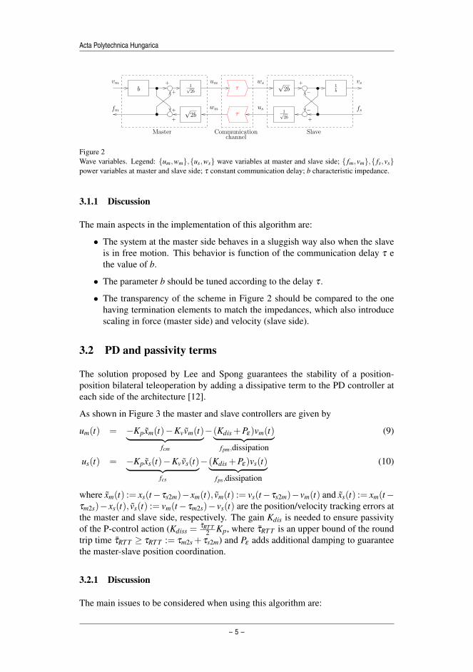
Figure 2Wave variables. Legend: {um,wm},{us,ws} wave variables at master and slave side; { fm,vm},{ fs,vs}power variables at master and slave side; τ constant communication delay; b characteristic impedance.
3.1.1 Discussion
The main aspects in the implementation of this algorithm are:
• The system at the master side behaves in a sluggish way also when the slaveis in free motion. This behavior is function of the communication delay τ ethe value of b.
• The parameter b should be tuned according to the delay τ .
• The transparency of the scheme in Figure 2 should be compared to the onehaving termination elements to match the impedances, which also introducescaling in force (master side) and velocity (slave side).
3.2 PD and passivity terms
The solution proposed by Lee and Spong guarantees the stability of a position-position bilateral teleoperation by adding a dissipative term to the PD controller ateach side of the architecture [12].
As shown in Figure 3 the master and slave controllers are given by
um(t) = −Kpxm(t)−Kvvm(t)︸ ︷︷ ︸fcm
−(Kdis +Pε)vm(t)︸ ︷︷ ︸fpm,dissipation
(9)
us(t) = −Kpxs(t)−Kvvs(t)︸ ︷︷ ︸fcs
−(Kdis +Pε)vs(t)︸ ︷︷ ︸fps,dissipation
(10)
where xm(t) := xs(t−τs2m)−xm(t), vm(t) := vs(t−τs2m)−vm(t) and xs(t) := xm(t−τm2s)−xs(t), vs(t) := vm(t−τm2s)−vs(t) are the position/velocity tracking errors atthe master and slave side, respectively. The gain Kdis is needed to ensure passivityof the P-control action (Kdiss =
τRT T2 Kp, where τRT T is an upper bound of the round
trip time τRT T ≥ τRT T := τm2s + τs2m) and Pε adds additional damping to guaranteethe master-slave position coordination.
3.2.1 Discussion
The main issues to be considered when using this algorithm are:
– 5 –
T
Placed Image
T
Placed Image
T
Typewriter
Vol. 13, No. 1, 2016
T
Typewriter
– 195 –

Riccardo Muradore and Paolo Fiorini A Review of Bilateral Teleoperation Algorithms
−
−
+
+
+
+
+
− +
fcs
+
fs
xsdvsd
xs Z−1s
+
+
Kp
Kv
Kdis
Pε
fps
vs
xs
vs
fm
+
+
−
−vmd
xmd
vm
xm
+
+
+
+
fpm
fcm
+ +
−+vm
xm
Pε
Kdis
Kv
Kp
Z−1m
Communicationchannel
SlaveMaster
τm2s
τs2m
Figure 3PD and passivity terms. Legend: Z−1
m master robot admittance, Z−1s slave robot admittance; Kp,Kv
position and velocity gains of the PD controller; Kdis,Pε dissipative terms; fm,xm,vm force, position andvelocity at the master side, fs,xs,vs force, position and velocity at the slave side; fcm, fcs force controlsat the master and slave side, fpm, fps passivity-related forces.
• The effect of the discretization and of the velocity estimation.
• The speed of the system response as a function of Kdis (and so of Kp andτRT T ).
• The effect of the values of Kp and Kv at the master and slave sides.
• The effect of Pε on the level of transparency.
• The on-line adaptation of Kdis according to the measured delay.
3.3 Adaptive algorithm
The algorithm presented in this section for the constant communication delay sce-nario makes use of adaptive control to guarantee the passivity of the system [13].In this algorithm, the PD controllers of the previous approach are replaced by anequivalent proportional controller on the new variables:
rm(t) := vm(t)+λxm(t) (11)rs(t) := vs(t)+λxs(t) (12)
where λ > 0 is a tuning parameter. The overall architecture is shown in Figure 4where the Adaptive Estimation blocks estimate the inertia and damping parametersof the DC motor at the slave and master side using an adaptive algorithm.[
˙Jm(t)˙Bm(t)
]= ΓmY T
m (xm(t),rm(t))rm(t) (13)[˙Js(t)˙Bs(t)
]= ΓsY T
s (xs(t),rs(t))rs(t) (14)
– 6 –
T
Placed Image
T
Typewriter
– 196 –
T
Placed Image
T
Typewriter
R. Muradore et al.

Acta Polytechnica Hungarica Vol. ??, No. ?, 20??
where Γm,Γs are constant positive definite matrices and Ym,Ys are the regressionmatrices.
The overall master and slave controls are computed as:
um(t) = fmc(t)− Jm(t)λvm(t)− Bm(t)λxm(t) (15)us(t) = fsc(t)− Js(t)λvs(t)− Bs(t)λxs(t) (16)
where fmc(t) and fsc(t) are the coordinating torques
fmc(t) = K(rm(t)− rs(t− τs2m)) (17)fsc(t) = K(rs(t)− rm(t− τm22)). (18)
τm2s
τs2m
Communicationchannel
SlaveMaster
Z−1m
fm
−+
λvm
xmrm
AdaptiveEstimation
+
−K
rmdrm
+
+
+
λrs
+
−K
+
+ fsvsxs
fps
fcsrsrsd
+
+
+ fpm
fcm
Z−1s +
−
AdaptiveEstimation
Figure 4Adaptive-based algorithm. Legend: Z−1
m master robot admittance, Z−1s slave robot admittance; K gain
of the controller; fm,xm,vm force, position and velocity at the master side, fs,xs,vs force, position andvelocity at the slave side; λ tuning parameter; fcm, fcs force controls at the master and slave side, fpm,fps passivity-related forces.
3.3.1 Discussion
The main steps for the practical implementation of this algorithm are:
• The effect of the discretization on the adaptive estimation.
• System transparency as a function of K, λ , Γm,Γs.
• The computation of the value of K, assuming to exactly know the dynamicparameters of the motors, and of λ to ensure the equivalence of this algorithmto the algorithm presented in the previous section.
4 Bilateral teleoperation with time-varying communi-cation delay
In this section we address the case of bilateral teleoperation when the communica-tion delay is time-varying and unknown. We present three solutions that share the
– 7 –
T
Placed Image
T
Placed Image
T
Typewriter
Vol. 13, No. 1, 2016
T
Typewriter
– 197 –

Riccardo Muradore and Paolo Fiorini A Review of Bilateral Teleoperation Algorithms
same idea: the passivity is guaranteed in the time domain by computing the energybalance at run time.
4.1 Time Domain Passivity Approach
The Time Domain Passivity Approach (TDPA) proposed in [14] uses two tools toevaluate the energy and to cope with energy shortage:
• The passivity observers PO compute the monotonically increasing energy leav-ing or entering the master and the slave side
E∗in(k) =
{E∗in(k−1)+TsP∗(k), if P∗(k)> 0E∗in(k−1), if P∗(k)≤ 0 (19)
E∗out(k) =
{E∗out(k−1)−TsP∗(k), if P∗(k)< 0E∗out(k−1), if P∗(k)≥ 0 (20)
where ∗ = m,s, P∗(k) = f∗(k)v∗(k) is the actual discrete-time power com-puted at time t = kTs, with Ts the sample time.
• The passivity controllers PC intervene any time an unstable behavior is goingto be applied by activating dissipative elements
βk =
{∆Es(k)Ts f 2
sdif ∆Es(k)> 0 and fsd 6= 0
0 if ∆Es(k)≤ 0(21)
αk =
{∆Em(k)Tsv2
mdif ∆Em(k)> 0 and vmd 6= 0
0 if ∆Em(k)≤ 0(22)
where
∆Es(k) := Esout(k)−Em
in(k− τm2s(k)) (23)∆Em(k) := Em
out(k)−Esin(k− τs2m(k)). (24)
Figure 5 shows this architecture where also low pass filters F are implemented in abi-directional fashion (to preserve passivity) to reduce bumps and oscillations at theoperator side.
4.1.1 Discussion
The following are important considerations that a designer using this algorithmshould consider:
• How conservative is this “distributed” energy control.
• The effect of the communication delay on the performance of the TDPA al-gorithm.
• If and how to implement a position-position teleoperation instead of the pro-posed position-force scheme.
– 8 –
T
Placed Image
T
Typewriter
– 198 –
T
Placed Image
T
Typewriter
R. Muradore et al.

Acta Polytechnica Hungarica Vol. ??, No. ?, 20??
τm2s
τm2s
Z−1s
τs2m
Esout
Communicationchannel
SlaveMaster
Z−1m Cs
+ +
βk
PO
PO
Emin
Esin
τs2mEmout
fs+
vsd vs
fscfsc
vsd
−
βk
+−
+
fm
−
αk
F
F
αk
+
+ fmdfmc
vm vlpm
fmd
Figure 5TDPA algorithm. Legend: Z−1
m master robot admittance, Z−1s slave robot admittance; Cs velocity
controller; fm,vm force and velocity at the master side, fs,vs force and velocity at the slave side;vsd(t) = vl p
m (t − τm2s) desired velocity at the slave side with vl pm = F(s)vm, vsd modified velocity ref-
erence, fmd(t) = fsc(t− τs2c) desired force, fmd modified force reference with fmd = F(s) fmd .
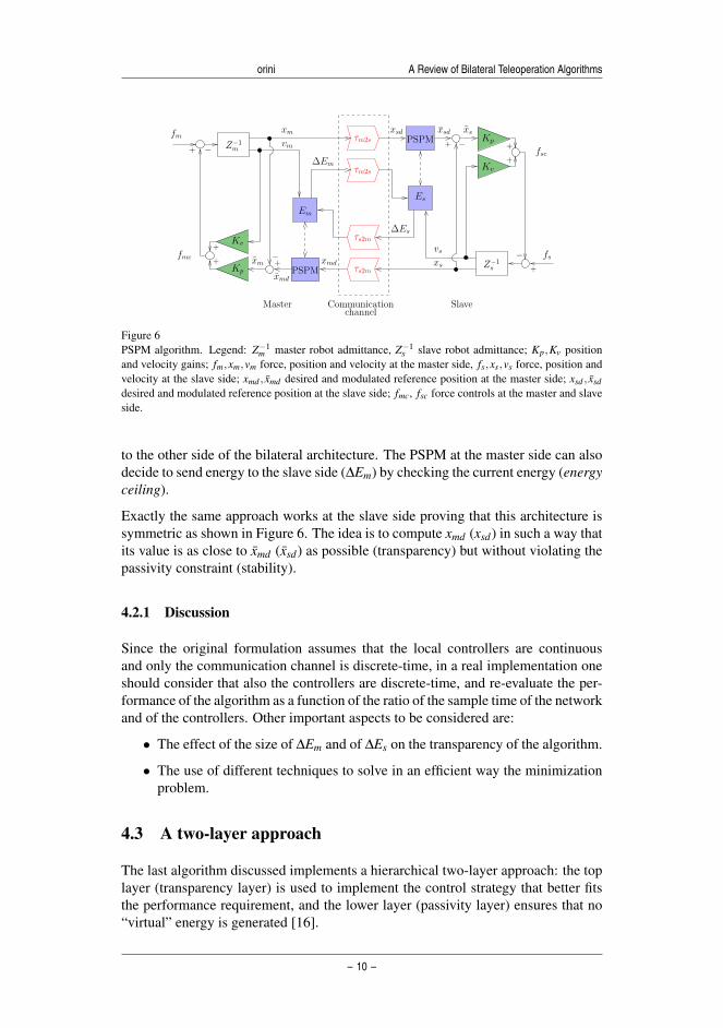
4.2 Passive Set-Position Modulation
The Passive Set-Position Modulation (PSPM) algorithm is another approach to mod-ify the value of the reference signal received from the master or the slave to complywith the passivity constraint.
The scheme proposed in [15] is a position-position teleoperation architecture wherethe original set-position signal (xmd or xsd ) is modulated in such a way that the new value (x¯md or x¯sd ) satisfies the passivity constraint when applied to a springKp(x∗(t)− x∗d(k)) with damping injection Kvv∗, ∗= m,s.
The novelty of this approach is to explicitly consider the possibly of passivity-breaking due to spring energy jumps at the switching instances. The scheme isshown in Figure 6 where Em is the virtual energy reservoirs at the master, and thePSPM block solves the following minimization problem any time a new referencevalue is received:
minxmd(k) ‖xmd(k)− xmd(k)‖ (25)s.to Em(k−1)+∆Es(k)+Dm(k−1)−∆Pm(k)≥ 0
where Em(k−1) is the available energy, ∆Es(k) is the energy received by the slave(energy-shuffling), Dm(k−1) is the causal approximation of the damping dissipation(energy reharvesting, 1
2 Kvx2m(k)) and ∆Pm(k) is the spring energy jump
∆P(k) =12‖xm(k)− xmd(k)‖2
Kp −12‖xm(k)− xmd(k−1)‖2
Kp (26)
In this algorithm, the local controllers are assumed continuous: in real implementa-tion we can only assume that the local controllers have a sample time Ts smaller thanthe sample time at which the slave and master send their commands/measurements
– 9 –
T
Placed Image
T
Placed Image
T
Typewriter
Vol. 13, No. 1, 2016
T
Typewriter
– 199 –
Riccardo Muradore and Paolo Fiorini A Review of Bilateral Teleoperation Algorithms
τm2s
τm2s
τs2m
τs2m
Es
PSPM
Z−1m
Em
Communicationchannel
SlaveMaster
Kv
Kp
xsd xsd
fsc
∆Es
vsxs
fs+
−
−+
xs
Z−1s
fm
−+
fmc xmd
+
+
Kv
Kp
xmvm
xm
xmd
−+
∆Em+
+PSPM
Figure 6PSPM algorithm. Legend: Z−1
m master robot admittance, Z−1s slave robot admittance; Kp,Kv position
and velocity gains; fm,xm,vm force, position and velocity at the master side, fs,xs,vs force, position andvelocity at the slave side; xmd , xmd desired and modulated reference position at the master side; xsd , xsddesired and modulated reference position at the slave side; fmc, fsc force controls at the master and slaveside.
to the other side of the bilateral architecture. The PSPM at the master side can alsodecide to send energy to the slave side (∆Em) by checking the current energy (energyceiling).
Exactly the same approach works at the slave side proving that this architecture issymmetric as shown in Figure 6. The idea is to compute xmd (xsd) in such a way thatits value is as close to xmd (xsd) as possible (transparency) but without violating thepassivity constraint (stability).
4.2.1 Discussion
Since the original formulation assumes that the local controllers are continuousand only the communication channel is discrete-time, in a real implementation oneshould consider that also the controllers are discrete-time, and re-evaluate the per-formance of the algorithm as a function of the ratio of the sample time of the networkand of the controllers. Other important aspects to be considered are:
• The effect of the size of ∆Em and of ∆Es on the transparency of the algorithm.
• The use of different techniques to solve in an efficient way the minimizationproblem.
4.3 A two-layer approach
The last algorithm discussed implements a hierarchical two-layer approach: the toplayer (transparency layer) is used to implement the control strategy that better fitsthe performance requirement, and the lower layer (passivity layer) ensures that no“virtual” energy is generated [16].
– 10 –
T
Placed Image
T
Typewriter
– 200 –
T
Placed Image
T
Typewriter
R. Muradore et al.

Acta Polytechnica Hungarica Vol. ??, No. ?, 20??
The scheme is reported in Figure 7 for a position-force configuration. It is inter-esting to see that the approach of this algorithm is similar to the one of the twoprevious solutions but the passivity verification is done after the computation of thecommands and not before.
τm2s
τm2s
τs2m
Es
Z−1s
τs2m
EmUpperBound
UpperBound
Communicationchannel
SlaveMaster
Z−1m
xm
Kv
Kp−+
xs
+
+
+
−
fm
−+
fs
fmc
fmd
∆Em
∆Es
fsd
fscvsxs
xsd
Figure 7Hierarchical two-layer approach. Legend: Z−1
m master robot admittance, Z−1s slave robot admittance;
Kp,Kv position and velocity gains; fm,xm,vm force, position and velocity at the master side, fs,xs,vsforce, position and velocity at the slave side; fmd , fmc desired and modulated forces at the master side;fsd , fsc desired and modulated force at the slave side.
The level of the energy tank Em (the same hold for Es) consists of three terms
Em(k) = Em(k−1)+Es2m(k)−EH(k) (27)
where Em(k− 1) is the past value of the energy, Es2m(k) = ∆Es(k− τs2m) is theenergy received by the slave side and EH(k) is the energy exchange between thediscrete-time controller and physical world. It is computed as
EH(k) = um(k)(xm(k)− xm(k−1)) (28)
where um(k) is the torque applied to the motor over the interval [k−1,k].
This energy is used to compute an upper bound for the command to guarantee thestability of the teleoperated system, e.g. umax
m = Em(k)vm(k)Ts
where Ts is the sample timeof the local controller and vm(k) is an estimation of the future velocity.
If Em(k) is large enough the master sends energy Em2s(k) to the slave side and up-dates Em(k) accordingly
Em(k)← Em(k)−Em2s(k). (29)
The same architecture is implemented at the slave side as shown in Figure 7.
– 11 –
T
Placed Image
T
Placed Image
T
Typewriter
Vol. 13, No. 1, 2016
T
Typewriter
– 201 –

Riccardo Muradore and Paolo Fiorini A Review of Bilateral Teleoperation Algorithms
4.3.1 Discussion
Additional points to be considered are:
• The implementation of a position-position structure within the hierarchicaltwo-layer approach.
• The use of different policies for the master-slave energy exchange.
• The amount of energy present “in the network” as a function of τm2s,τm2s andthe energy transfer policy.
5 Experimental setup
The experimental setup is shown in Figure 8 and it supports the implementation ofC++ different types of control architecture in a real time middleware. This teleop-eration architecture has one degree of freedom: this simplifies the analysis becausewe can avoid the complication of nonlinear control of multi-input multi-output ma-nipulators, and is also more suitable to educational purpose and to compare thealgorithms’ characteristics.
Figure 8Bilateral teleoperation test bench.
The hardware consists of two DC motors, a gear at the master side with ratio equalto 4, two single axis force sensors mounted on rods, and a control board. The boardhas an interface to a BeckhoffTM EtherCAT R© controller. The motor controllers arelogically separated at software level sharing only the physical communication bus.
The software is developed in OROCOS [17], an open source component-based frame-work for robotic applications developed by K.U. Leuven, Belgium, in collaboration with LAAS Toulouse, France, and KTH, Sweden. It allows program flexibility (in C++), real time performance and code reusability.
– 12 –
T
Placed Image
T
Typewriter
– 202 –
T
Placed Image
T
Typewriter
R. Muradore et al.
Acta Polytechnica Hungarica Vol. ??, No. ?, 20??
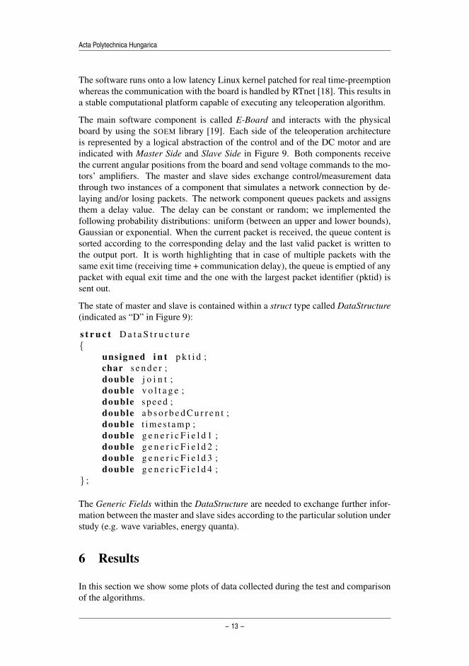
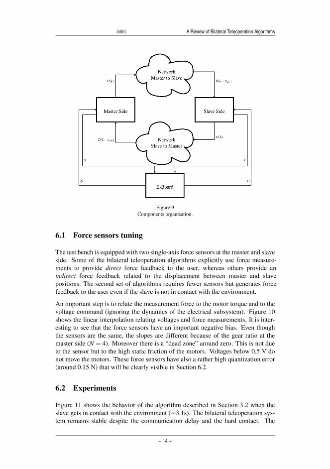
The software runs onto a low latency Linux kernel patched for real time-preemptionwhereas the communication with the board is handled by RTnet [18]. This results ina stable computational platform capable of executing any teleoperation algorithm.
The main software component is called E-Board and interacts with the physicalboard by using the SOEM library [19]. Each side of the teleoperation architectureis represented by a logical abstraction of the control and of the DC motor and areindicated with Master Side and Slave Side in Figure 9. Both components receivethe current angular positions from the board and send voltage commands to the mo-tors’ amplifiers. The master and slave sides exchange control/measurement datathrough two instances of a component that simulates a network connection by de-laying and/or losing packets. The network component queues packets and assignsthem a delay value. The delay can be constant or random; we implemented thefollowing probability distributions: uniform (between an upper and lower bounds),Gaussian or exponential. When the current packet is received, the queue content issorted according to the corresponding delay and the last valid packet is written tothe output port. It is worth highlighting that in case of multiple packets with thesame exit time (receiving time + communication delay), the queue is emptied of anypacket with equal exit time and the one with the largest packet identifier (pktid) issent out.
The state of master and slave is contained within a struct type called DataStructure(indicated as “D” in Figure 9):
s t r u c t D a t a S t r u c t u r e{
unsigned i n t p k t i d ;char s e n d e r ;double j o i n t ;double v o l t a g e ;double speed ;double a b s o r b e d C u r r e n t ;double t imes t amp ;double g e n e r i c F i e l d 1 ;double g e n e r i c F i e l d 2 ;double g e n e r i c F i e l d 3 ;double g e n e r i c F i e l d 4 ;
} ;
The Generic Fields within the DataStructure are needed to exchange further infor-mation between the master and slave sides according to the particular solution understudy (e.g. wave variables, energy quanta).
6 Results
In this section we show some plots of data collected during the test and comparisonof the algorithms.
– 13 –
T
Placed Image
T
Placed Image
T
Typewriter
Vol. 13, No. 1, 2016
T
Typewriter
– 203 –
Riccardo Muradore and Paolo Fiorini A Review of Bilateral Teleoperation Algorithms
Figure 9Components organisation.
6.1 Force sensors tuning
The test bench is equipped with two single-axis force sensors at the master and slave side. Some of the bilateral teleoperation algorithms explicitly use force measure-ments to provide direct force feedback to the user, whereas others provide an indirect force feedback related to the displacement between master and slave positions. The second set of algorithms requires fewer sensors but generates force feedback to the user even if the slave is not in contact with the environment.
An important step is to relate the measurement force to the motor torque and to thevoltage command (ignoring the dynamics of the electrical subsystem). Figure 10shows the linear interpolation relating voltages and force measurements. It is inter-esting to see that the force sensors have an important negative bias. Even thoughthe sensors are the same, the slopes are different because of the gear ratio at themaster side (N = 4). Moreover there is a “dead zone” around zero. This is not dueto the sensor but to the high static friction of the motors. Voltages below 0.5 V donot move the motors. These force sensors have also a rather high quantization error(around 0.15 N) that will be clearly visible in Section 6.2.
6.2 Experiments
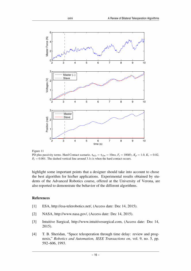
Figure 11 shows the behavior of the algorithm described in Section 3.2 when theslave gets in contact with the environment (∼3.1s). The bilateral teleoperation sys-tem remains stable despite the communication delay and the hard contact. The
– 14 –
T
Placed Image
T
Typewriter
– 204 –
T
Placed Image
T
Typewriter
R. Muradore et al.

Acta Polytechnica Hungarica Vol. ??, No. ?, 20??
0 0.5 1 1.5 2 2.5 3 3.5−1
−0.5
0
0.5
1
1.5
2
2.5
3
3.5
Voltage (V)
Fo
rce
(N
)
Master
Slave
Figure 10Calibration of the force sensors.
voltages at the master and slave side have very similar values (in absolute value butopposite signs) and are strongly correlated to the force measurements at the masterside.
After the contact, the position of the slave does not change whereas the master force is proportional to the difference between the master and slave positions. The temporal misalignment that can be seen in the master and slave voltages is mainly due to the round trip time τm2s + τs2m and partially on the haptic paddle dynamics and the control parameters (Kp,Kv and Kdis,Pε ). High values for τm2s,τs2m imply a high value for Kdis: the system behaves in a sluggish manner. This is the price to pay to have the system passive with high round trip time.
The plots in Figure 12 show how the PSPM algorithm of Section 4.2 modulates thedesired reference position xsd when the energy level Es is close to zero. In this casethere is no contact but the instability arises due to the discretization and the fastmovement compared with the energy shuffling and reharvesting. Any time there isa lack of energy (positive energy in the bottom plot in the figure) the minimizationproblem (25) determines the proper modulated reference position xsd to satisfy thestability constraint.
ConclusionsIn this paper we reviewed classic and more recent algorithms that guarantee the stability of bilateral teleoperation systems. The crucial concept of passivity is im-plemented in each algorithm in different forms to safely interact with unknown en-vironment despite communication delay from the master and slave sides. We list the assumptions behind each algorithm, their advantages and disadvantages, and we
– 15 –
T
Placed Image
T
Placed Image
T
Typewriter
Vol. 13, No. 1, 2016
T
Typewriter
– 205 –
Riccardo Muradore and Paolo Fiorini A Review of Bilateral Teleoperation Algorithms
2 3 4 5 6 7 8 9 100
2
4
6
Maste
r F
orc
e (
N)
2 3 4 5 6 7 8 9 100
1
2
3
Voltages (
V)
Master (−)
Slave
2 3 4 5 6 7 8 9 100
1
2
3
Positio
n (
rad)
time (s)
Master
Slave
Figure 11PD plus passivity terms. Hard Contact scenario, τm2s = τs2m = 10ms, Fs = 100Hz, Kp = 1.0, Kv = 0.02,Pε = 0.001. The dashed vertical line around 3.1s is when the hard contact occurs.
highlight some important points that a designer should take into account to chose the best algorithm for his/her applications. Experimental results obtained by stu-dents of the Advanced Robotics course, offered at the University of Verona, are also reported to demonstrate the behavior of the different algorithms.
References
[1] ESA, http://esa-telerobotics.net/, (Access date: Dec 14, 2015).
[2] NASA, http://www.nasa.gov/, (Access date: Dec 14, 2015).
[3] Intuitive Surgical, http://www.intuitivesurgical.com, (Access date: Dec 14,2015).
[4] T. B. Sheridan, “Space teleoperation through time delay: review and prog-nosis,” Robotics and Automation, IEEE Transactions on, vol. 9, no. 5, pp.592–606, 1993.
– 16 –
T
Placed Image
T
Typewriter
– 206 –
T
Placed Image
T
Typewriter
R. Muradore et al.

Acta Polytechnica Hungarica Vol. ??, No. ?, 20??
42 42.5 43 43.5 44 44.5 45 45.5−1.5
−1
−0.5
0
0.5
1
Positio
n (
rad)
Master Position
Slave Reference
Slave Position
42 42.5 43 43.5 44 44.5 45 45.50
0.1
0.2
0.3
0.4
Time (s)
Sla
ve E
nerg
y (
Joule
)
Slave Energy
Figure 12PSPM algorithm. τM2S = τS2M = 10ms, Fctrl
s = 500Hz, Fnetworks = 100Hz, Kp = 1.0, Kv = 0.01.
[5] P. F. Hokayem and M. W. Spong, “Bilateral teleoperation: An historical sur-vey,” Automatica, vol. 42, no. 12, pp. 2035–2057, 2006.
[6] E. Nuno, L. Basanez, and R. Ortega, “Passivity-based control for bilateralteleoperation: A tutorial,” Automatica, vol. 47, no. 3, pp. 485–495, 2011.
[7] Aliaga, I., A. Rubio, and E. Sanchez, “Experimental quantitative compari-son of different control architectures for master-slave teleoperation,” ControlSystems Technology, IEEE Transactions on, vol. 12, no. 1, pp. 2–11, 2014.
[8] De Gersem, G., H. Van Brussel, and F. Tendick, “Reliable and enhanced stiff-ness perception in soft-tissue telemanipulation,” The International Journal ofRobotics Research, vol. 24, no. 10, pp. 805–822, 2005.
[9] Malysz, P. and S. Sirouspour, “Nonlinear and filtered force/position map-pings in bilateral teleoperation with application to enhanced stiffness dis-crimination,”, Robotics, IEEE Transactions on, vol. 25, no. 5, pp. 1134–1149,2009.
[10] D. Lawrence, “Stability and transparency in bilateral teleoperation,” Roboticsand Automation, IEEE Transactions on, vol. 9, no. 5, pp. 624–637, 1993.
[11] G. Niemeyer and J.-J. E. Slotine, “Stable adaptive teleoperation,” OceanicEngineering, IEEE Journal of, vol. 16, no. 1, pp. 152–162, 1991.
[12] D. Lee and M. W. Spong, “Passive bilateral teleoperation with constant timedelay,” Robotics, IEEE Transactions on, vol. 22, no. 2, pp. 269–281, 2006.
– 17 –
T
Placed Image
T
Placed Image
T
Typewriter
Vol. 13, No. 1, 2016
T
Typewriter
– 207 –
Riccardo Muradore and Paolo Fiorini A Review of Bilateral Teleoperation Algorithms
[13] N. Chopra, M. W. Spong, and R. Lozano, “Synchronization of bilateral tele-operators with time delay,” Automatica, vol. 44, no. 8, pp. 2142–2148, 2008.
[14] J.-H. Ryu, J. Artigas, and C. Preusche, “A passive bilateral control schemefor a teleoperator with time-varying communication delay,” Mechatronics,vol. 20, no. 7, pp. 812–823, 2010.
[15] D. Lee and K. Huang, “Passive-set-position-modulation framework for inter-active robotic systems,” Robotics, IEEE Transactions on, vol. 26, no. 2, pp.354–369, 2010.
[16] M. Franken, S. Stramigioli, S. Misra, C. Secchi, and A. Macchelli, “Bilateraltelemanipulation with time delays: A two-layer approach combining passiv-ity and transparency,” Robotics, IEEE Transactions on, vol. 27, no. 4, pp.741–756, 2011.
[17] OROCOS, http://www.orocos.org, (Access date: Dec 14, 2015).
[18] RTnet, http://www.rtnet.org/, (Access date: Dec 14, 2015).
[19] SOEM, http://openethercatsociety.github.io/, (Access date: Dec 14, 2015).
– 18 –
T
Placed Image
T
Typewriter
– 208 –
T
Placed Image
T
Typewriter
R. Muradore et al.