A Review of Anthropomorphic Robotic Hand Technology and ... · iii A Review of Anthropomorphic...
141
A Review of Anthropomorphic Robotic Hand Technology and Data Glove Based Control Stephen Arthur Powell Thesis submitted to the faculty of the Virginia Polytechnic Institute and State University in partial fulfillment of the requirements for the degree of Master of Science In Mechanical Engineering Shashank Priya, Chair Andrew Kurdila Reza Mirzaeifar July 19, 2016 Blacksburg, VA Keywords: humanoid, anthropomorphic, hand, mechatronics, rapid prototyped, manipulation, data glove, human-machine interfaces, piezoluminescence Copyright © 2016 Stephen Arthur Powell
Transcript of A Review of Anthropomorphic Robotic Hand Technology and ... · iii A Review of Anthropomorphic...

i
A Review of Anthropomorphic Robotic Hand Technology and Data Glove
Based Control
Stephen Arthur Powell
Thesis submitted to the faculty of the Virginia Polytechnic Institute and
State University in partial fulfillment of the requirements for the degree of
Master of Science
In
Mechanical Engineering
Shashank Priya, Chair
Andrew Kurdila
Reza Mirzaeifar
July 19, 2016
Blacksburg, VA
Keywords: humanoid, anthropomorphic, hand, mechatronics, rapid
prototyped, manipulation, data glove, human-machine interfaces,
piezoluminescence
Copyright © 2016 Stephen Arthur Powell

ii
A Review of Anthropomorphic Robotic Hand Technology and Data Glove Based Control
Stephen Arthur Powell
For over 30 years, the development and control of anthropomorphic robotic hands has
been a highly popular sub-discipline in robotics research. Because the human hand is an
extremely sophisticated system, both in its mechanical and sensory abilities, engineers
have been fascinated with replicating these abilities in artificial systems. The applications
of robotic hands typically fall under the categories of standalone testbed platforms,
mostly to conduct research on manipulation, prosthetics, and robotic end effectors for
larger systems. The teleoperation of robotic hands is another application with significant
potential, where users can control a manipulator in real time to accomplish diverse tasks.
In controlling a device that seeks to emulate the function of the human hand, it is intuitive
to choose a human-machine interface (HMI) that will allow for the most intuitive control.
Data gloves are the ideal HMI for this need, allowing a robotic hand to accurately mimic
the human operator’s natural movements. In this paper we present a combined review on
the critical design aspects of data gloves and robotic hands. In literature, many of the
proposed designs covering both these topical areas, robotic hand and data gloves, are cost
prohibitive which limits their implementation for intended tasks. After reviewing the
literature, new designs of robotic hand and data glove technology are also presented,
introducing low cost solutions that can serve as accessible platforms for researchers,
students, and engineers to further the development of teleoperative applications.

iii
A Review of Anthropomorphic Robotic Hand Technology and Data Glove Based Control
Stephen Arthur Powell
For over 30 years, the development and control of anthropomorphic robotic hands has
been a highly popular sub-discipline in robotics research. Because the human hand is an
extremely sophisticated system, both in its mechanical and sensory abilities, engineers
have been fascinated with replicating these abilities in artificial systems. The applications
of robotic hands typically fall under the categories of standalone testbed platforms,
mostly to conduct research on manipulation, prosthetics, and robotic end effectors for
larger systems. The teleoperation of robotic hands is another application with significant
potential, where users can control a manipulator in real time to accomplish diverse tasks.
In controlling a device that seeks to emulate the function of the human hand, it is intuitive
to choose a human-machine interface (HMI) that will allow for the most intuitive control.
Data gloves are the ideal HMI for this need, allowing a robotic hand to accurately mimic
the human operator’s natural movements. In this paper we present a combined review on
the critical design aspects of data gloves and robotic hands. In literature, many of the
proposed designs covering both these topical areas, robotic hand and data gloves, are cost
prohibitive which limits their implementation for intended tasks. After reviewing the
literature, new designs of robotic hand and data glove technology are also presented,
introducing low cost solutions that can serve as accessible platforms for researchers,
students, and engineers to further the development of teleoperative applications.

iv
I would like to thank everyone who has helped me achieve my goals during my
educational journey here at Virginia Tech. I could not have done it without all of you.
A big thank you to my advisor, Dr. Shashank Priya, for giving me the
opportunity to pursue my dream of working in the field of robotics and his support over
my graduate school career.
I would also like to thank all of my lab mates for their assistance, advice, and
friendship.
Finally, I cannot forget to thank my family and friends who I have always been
able to count on for encouragement and love during this journey.

v
ABSTACT (Academic) .......................................................................................... ii
General Audience Abstract .................................................................................... iii
Acknowledgements ................................................................................................ iv
Attributions ........................................................................................................... xv
1. Introduction ..................................................................................................... 1
2. Overview of anthropomorphic hand designs in literature ............................... 3
2.1 Actuator Location ........................................................................................... 13
2.2 Actuator Configuration ................................................................................... 13
2.2.1. M < N ......................................................................................................... 14
2.2.2. M = N ......................................................................................................... 14
2.2.3. M > N ......................................................................................................... 14 2.2.3.1. M = 2N .............................................................................................................14 2.2.3.2. M = N + 1 .........................................................................................................14
2.3 Overview of Actuation Technology ................................................................ 15
2.3.1. DC Motors .................................................................................................. 15 2.3.1.1. Brushed DC motors ..........................................................................................15 2.3.1.2. Brushless DC (BLDC) motors ..........................................................................15
2.3.2. Pneumatic Air Muscles ............................................................................... 16
2.3.3. Hydraulics ................................................................................................... 16
2.4 Overview of Sensing Technology ................................................................... 16
2.4.1. Position Sensing ......................................................................................... 16 2.4.1.1. Hall Effect ........................................................................................................16 2.4.1.2. Optical ..............................................................................................................16 2.4.1.3. Potentiometers ..................................................................................................17
2.4.2. Force and Torque Sensing .......................................................................... 17 2.4.2.1. Strain Gauge Based ..........................................................................................17 2.4.2.2. Force Sensing Resistors ....................................................................................18
2.4.3. Tactile Sensing ........................................................................................... 18
2.5 Number of Fingers .......................................................................................... 18
2.6 Total number of joints, actuated DoF, and actuators ...................................... 18
2.7 Force Transmission Hardware ........................................................................ 19
2.7.1. Tendon Driven ............................................................................................ 19 2.7.1.1. Tendon-Sheath ..................................................................................................19 2.7.1.2. Tendon-pulley ..................................................................................................19
2.7.2. Gears ........................................................................................................... 20
2.7.3. Linkages...................................................................................................... 20
2.7.4. Belts ............................................................................................................ 21
2.7.5. Elastic elements .......................................................................................... 21
2.8 Design Purpose ............................................................................................... 22
2.9 Wrist, Forearms, and Integration .................................................................... 22
2.10 Cost ................................................................................................................. 22
2.11 Discussion of Select Designs .......................................................................... 23
2.11.1. Shadow Dexterous Hand (2005) ............................................................... 23
2.11.2. DART Hand (2011) .................................................................................. 24
2.11.3. Modular Prosthetic Limb (2011) .............................................................. 26
2.11.4. DLR Hand-Arm System (2012) ............................................................... 27

vi
2.11.5. Robonaut 2 Hand (2012) .......................................................................... 29
2.11.6. DEXMART Hand (2014) ......................................................................... 31
2.11.7. Sandia Hand (2014) .................................................................................. 32
3. The development and design of a low cost dexterous robotic hand ............. 34
3.1 The Human Hand ............................................................................................ 34
3.1.1. Anatomy ..................................................................................................... 34
3.1.2. Human Hand Kinematics ............................................................................ 35
3.2 Forearm Design ............................................................................................... 36
3.2.1. Actuation Methodology .............................................................................. 37 3.2.1.1. CAFSE Advantages Over Bi-directional Cables ..............................................38 3.2.1.2. CAFSE Advantages Over Direct Drive ............................................................39 3.2.1.3. CAFSE Limitations ..........................................................................................39
3.2.2. Actuator Selection ...................................................................................... 39
3.2.3. Motor Placement ......................................................................................... 40 3.2.3.1. Wrist .................................................................................................................40 3.2.3.2. Proximal finger phalanges and thumb phalanges .............................................40 3.2.3.3. Distal finger phalanges .....................................................................................40
3.2.4. Tendon-pulley and tendon-sheath network ................................................ 41
3.2.5. Elbow attachment to humanoid platform ................................................... 42
3.2.6. Wrist Design ............................................................................................... 44
3.3 Initial Hand Design ......................................................................................... 47
3.3.1. Dimensions and Range of Motion .............................................................. 47
3.3.2. Sensor Selection ......................................................................................... 50
3.3.3. Kinematics .................................................................................................. 51
3.3.4. Finger Design ............................................................................................. 53
3.3.5. Palm Design ................................................................................................ 54
3.3.6. Electronics and Control .............................................................................. 55
3.4 Testing of the Initial Design............................................................................ 57
3.4.1. Grasping Tests ............................................................................................ 57
3.4.2. Teleoperation via data glove ....................................................................... 58
3.4.3. Conclusions of Testing ............................................................................... 59
3.5 Updated Hand Design ..................................................................................... 60
3.5.1. Shaft-less Joints .......................................................................................... 61
3.5.2. Integrated Pulley ......................................................................................... 62
3.5.3. Tendon path routing .................................................................................... 63
3.5.4. Torsion Springs ........................................................................................... 64
3.5.5. Improved durability .................................................................................... 65
3.5.6. Improved Anthropomorphism and Modularity .......................................... 66
3.5.7. Grasp testing ............................................................................................... 68
3.5.8. Future work................................................................................................. 68
3.6 Impedance Control .......................................................................................... 69
3.6.1. Introduction ................................................................................................ 69
3.6.2. Overview of Impedance control ................................................................. 70
3.6.3. Need for impedance control in the sensor .................................................. 70
3.6.4. Proposed ‘Sensorless’ Impedance Control Methodology ........................... 70
3.6.5. Limitations of the Proposed Method .......................................................... 71
3.6.6. Experimental Setup ..................................................................................... 71
3.6.7. Control Law ................................................................................................ 72
3.6.8. Control Results ........................................................................................... 73
4. Review of Data Glove Control ..................................................................... 73

vii
4.1 Need for Teleoperation ................................................................................... 73
4.2 Current Control Options.................................................................................. 74
4.3 Data Glove Technology .................................................................................. 75
4.4 Sensing Methods ............................................................................................. 79
4.4.1. Spatial tracking ........................................................................................... 79 4.4.1.1. Visual ...............................................................................................................80 4.4.1.2. Magnetic ...........................................................................................................80 4.4.1.3. Optical ..............................................................................................................81
4.4.2. Indirect tracking .......................................................................................... 81 4.4.2.1. Magnetic sensing ..............................................................................................81 4.4.2.2. Inertial sensing .................................................................................................82
4.4.3. Direct angle measurement .......................................................................... 82 4.4.3.1. Rotary encoders and potentiometers .................................................................83 4.4.3.2. Fiber optic bend sensors ...................................................................................83
5. The Design of a Low Cost Data Glove ......................................................... 85
5.1 Sensor Analysis ............................................................................................... 85
5.2 Sensor Placement ............................................................................................ 86
5.3 Glove Selection ............................................................................................... 87
5.4 Testing the Data Glove ................................................................................... 90
5.5 Results ............................................................................................................. 92
5.6 Noted issues and Future Fixes ........................................................................ 94
5.7 Method to Control the Robot .......................................................................... 94
5.8 Labview Code ................................................................................................. 95
5.9 Future Work .................................................................................................... 98
5.10 Exploration of a PZL Based Data Glove ........................................................ 99
5.10.1. Piezoluminenscence .................................................................................. 99
5.10.2. Fabrication of PZL rubber ........................................................................ 99
5.10.3. A working basis of proposed system ...................................................... 100
5.10.4. Additional PZL-based sensor concepts .................................................. 102
5.10.5. Current challenges of PZL material in a data glove design .................... 103
6. Summary and Conclusion ........................................................................... 104
7. Future Work ................................................................................................ 105
References ........................................................................................................... 106
Appendix A: Copyright Permissions .................................................................. 120

viii
List of Figures
Figure 1. The Shadow Dexterous Hand (Shadow, 2013). Used under fair use, 2016 (see
Appendix A).............................................................................................................. 24
Figure 2. The DART Hand (Thayer & Priya, 2011). Used under fair use, 2016 (see
Appendix A).............................................................................................................. 26
Figure 3. The Modular Prosthetic Limb (Wester et al., 2013). Reprinted with permission,
© 2013 IEEE (see Appendix A). .............................................................................. 27
Figure 4. The DLR Hand-Arm System (a) hand and (b) forearm. (Grebenstein et al.,
2011). Reprinted with permission, © 2011 IEEE (see Appendix A). ....................... 29
Figure 5. The Robonaut 2 Hand (NASA, 2010). Reprinted from NASA (see Appendix
A). ............................................................................................................................. 30
Figure 6. The DEXMART Hand (Palli et al., 2014). Reprinted with permission, © 2014
SAGE Publications (see Appendix A). ..................................................................... 32
Figure 7. The Sandia Hand (Sandia National Laboratories, 2015). Used under fair use,
2016 (see Appendix A). ............................................................................................ 33
Figure 8. The bones and joints of the human hand (wpclipart). Used under fair use, 2016
(see Appendix A). ..................................................................................................... 34
Figure 9. Cutkosky’s Taxonomy of human hand grasps (Cutkosky & Howe, 1990). Used
under fair use, 2016 (see Appendix A). .................................................................... 36
Figure 10. (a) Wrist rotation is accomplished through the use of two parallel motors
which can be driven separately or simultaneously, producing two DoF. (b) The
upper chassis contains the motors to actuate proximal DoF for each of the fingers
and the flexion DoFs for the thumb. (c) The four motors that actuate the distal DoF
for the fingers, along with the elbow rotation motor, are contained in the lower
motor chassis. ............................................................................................................ 40
Figure 11. (a) Pulley network which is routed through channels inlaid in forearm surface.
(b) Upon reaching the tip of the forearm, the tendons flow through the u-joint into
the hand via tendon sheaths which reduce friction and possibility of uncommanded
finger actuation. (c) Due to relatively straight path of tendons on the bottom of the
forearm, Tendon sheaths are sufficient to transmit the power of the distal motors. . 42
Figure 12. The DASH hands attached to an 8 DoF robotic upper body system. .............. 43

ix
Figure 13. The assembly of the elbow rotation mechanism is comprised of the following
components (from left to right): servo with two gear train, elbow hub, needle thrust
bearing, radial bearing, elbow cap, needle thrust bearing, elbow mounting bracket.44
Figure 14. The Pololu Mini-Maestro servo controller located in the elbow of the forearm.
................................................................................................................................... 44
Figure 15. The evolution of the wrist U-Joint (a) in-plane wide u-joint, (b) split-plane thin
member u-joint, (c) split-plane thickened member u-joint, and (d) final split-plane u-
joint 3D printed in stainless steel and sintered bronze (Stevens, 2013). Reprinted
with permission (see Appendix A). .......................................................................... 45
Figure 16. Differential actuation method provides 2 DoF in the wrist. Metal rods connect
the servo horns to the base of the palm with ball joints. ........................................... 46
Figure 17. The wrist of the DASH Hand supporting a 2.56 kg weight (Stevens, 2013).
Reprinted with permission (see Appendix A). .......................................................... 46
Figure 18. Human hand critical dimensions for the average male of 40 years of age
(NASA, 2000). Reprinted from NASA (see Appendix A). ...................................... 48
Figure 19. DASH hand design with proximal, medial and distal links of the fingers shown
light blue, green and red respectively. The palm is shown in dark blue and each of
the fingers attaches to the palm via the pink u-joints (Stevens, 2013). Reprinted with
permission (see Appendix A).................................................................................... 49
Figure 20. (a) Abduction of index is 25° for the fingers and up to 80° for the thumb. (b)
Actual measurements for index and pinky abduction were measured closer to 31°.
(c) Final model shows the same range of motion was achieved. Reprinted from
"Design and Teleoperative Control of Humanoid Robot Upper Body for Task-driven
Assistance" by M. Stevens, 2013. Reprinted with permission (see Appendix A). ... 50
Figure 21. The integrated Flexpoint bend sensors (Stevens, 2013). Reprinted with
permission (see Appendix A).................................................................................... 51
Figure 22. Kinematic model of hand. Each blue cylinder represents a rotational degree of
freedom. The distal and medial joints are coupled for each of the fingers. The wrist
is driven by a differentially actuated mechanism design (Stevens, 2013). Reprinted
with permission (see Appendix A). .......................................................................... 51

x
Figure 23. Finger flexion of medial phalange coupled with distal phalange using a four
bar linkage mechanism (Stevens, 2013). Reprinted with permission (see Appendix
A). ............................................................................................................................. 52
Figure 24. (a) Full finger flexion is possible with the use of 11 actuated degrees of
freedom. (b) Widening the grip size is accomplished with the three servos located in
the hand responsible for abduction. (c) The neutral position shown is the condition
where none of the motors were actuated (Stevens, 2013). Reprinted with permission
(see Appendix A). ..................................................................................................... 53
Figure 25. (a) the DASH hand is compared to a human hand to give a sense of
dimensional accuracy. (b) Intrinsic motor placement for abduction of the thumb,
index and pinky joints. (c) Palm design of intrinsic motors including the
microcontroller and tendon routing (Stevens, 2013). Reprinted with permission (see
Appendix A).............................................................................................................. 55
Figure 26. Arduino-based Teensy board measuring 35.5mm in width and 17.8mm in
length (Stevens, 2013). Reprinted with permission (see Appendix A). .................... 55
Figure 27. Voltage Divider where Vin = 3.3V, R1= Bend Sensor, Vout = Analog Reading,
and R2 = fixed resistor. ............................................................................................. 56
Figure 28. Simplified circuit diagram showing the first four flexion sensors with cascaded
voltage dividers (Stevens, 2013). Reprinted with permission (see Appendix A). .... 57
Figure 29. The DASH Hand demonstrating the grasps of Cutkosky’s Taxonomy,
accomplishing 15 of the 16 grasps. ........................................................................... 58
Figure 30. The DASH Hand teleoperated by data glove. ................................................. 59
Figure 31. Damage of the plastic structure of the DASH Hand. Damage prone areas
included the locations of the revolute pin joints, as well as the screws that secure the
tendons. ..................................................................................................................... 60
Figure 32. The deformed spring steel after repeated use. ................................................. 60
Figure 33. An exploded view of the finger, showing the shaft-less joint design, comprised
of cantilevered hubs with radial bearings. ................................................................ 61
Figure 34. A cutaway view of the finger, showing the tendon channel of the proximal
phalange. ................................................................................................................... 62
Figure 35. The integrated pulley of the MC joint of the proximal phalange. ................... 62

xi
Figure 36. The tendon routing of both the (a) proximal and (b) medial phalange in the
fully extended as well as in the (c) proximal and (d) medial phalanges in the fully
flexed positions. ........................................................................................................ 64
Figure 37. A press fit section of the integrated pulley is slid away to allow the torsion
spring to be released.................................................................................................. 65
Figure 38. Mechanical limits restrict the flexion range of motion to 90°. ........................ 66
Figure 39. The encapsulated four bar linkage mechanism that is responsible for coupling
the PIP and DIP movement. ...................................................................................... 66
Figure 40. The updated hand design, featuring more a more anthropomorphic form which
contributes to enhanced functionality and robustness. ............................................. 67
Figure 41. The updated hand performing the grasps of Cutkosky’s Taxonomy. ............. 68
Figure 42. An analog Hall Effect sensor with magnet shown on a phalange prototype. .. 69
Figure 43. A schematic for the experimental setup of the ‘sensorless’ impedance
controller. .................................................................................................................. 72
Figure 44. Experimental results of the impedance control of the servomotor. ................. 73
Figure 45. The DASH Hand, shown in comparison with an adult male hand (Stevens,
2013). Reprinted with permission (see Appendix A). .............................................. 74
Figure 46. Flexpoint bend sensors, in 1", 2", and 3” lengths (Saggio, et al., 2014). Used
under Open Access. .................................................................................................. 84
Figure 47. Voltage divider diagram. R1 is the sensor, and R2 is the static reference
resistor. ...................................................................................................................... 86
Figure 48. Circular grip (left) and power grip (right) are ideal grips for a number of
teleoperative purposes. (Online Digital Education Connection, 2011). Used under
fair use, 2016 (see Appendix A). .............................................................................. 87
Figure 49. Data schematic (above) and the physical data glove prototype (below), with
sensors attached to dual lock tabs, but without wires. Note that the proximal sensors
are free to slide beneath the distal sensors to prevent sensor buckling (Paluszek,
2013). Reprinted with permission (see Appendix A). .............................................. 89
Figure 50. Tracking points on the data glove. A net total of five points were needed to
accomplish tracking, having one dot along the palm of the hand, the proximal

xii
knuckle, the proximal digit, the medial knuckle, and the medial digit (Paluszek,
2013). Reprinted with permission (see Appendix A). .............................................. 90
Figure 51. Data Glove with tracking points (above) and link segment model (below).
Each dot is recorded as a series of x and y coordinate pixels, which were used to find
the relative positions of each link (Paluszek, 2013). Reprinted with permission (see
Appendix A).............................................................................................................. 91
Figure 52. Proximal Angle vs. voltage with linear fit (above), Distal Angle vs. voltage
with linear fit (below) (Paluszek, 2013). Reprinted with permission (see Appendix
A). ............................................................................................................................. 93
Figure 53. Data glove in the extended position (left) and at 25 degrees of flexion (right).
Note the sensor is not in contact with the proximal knuckle in the extended position,
but is in contact in the flexed position (Paluszek, 2013). Reprinted with permission
(see Appendix A). ..................................................................................................... 93
Figure 54. Simple flow chart explaining the process of obtaining, parsing and using
signals to control the robotic hand (Paluszek, 2013). Reprinted with permission (see
Appendix A).............................................................................................................. 95
Figure 55. Neutral Hand Position (top), distal finger flexion (middle), proximal finger
flexion (bottom) (Paluszek, 2013). Reprinted with permission (see Appendix A). . 96
Figure 56. Thumb distal flexion (top) and thumb proximal flexion (bottom) (Paluszek,
2013). Reprinted with permission (see Appendix A). .............................................. 97
Figure 57. Piezoluminescent rubber (a) and (b) piezoluminescence under stretching-
releasing motion, (c) and (d) piezoluminescence rubber applied on cotton glove. 100
Figure 58. A photodiode array designed to function as a camera (Nayar, et al., 2015).
Reprinted with permission, © 2015 IEEE (see Appendix A). ................................ 101
Figure 59. Photodiode arrays arranged to sense the PZL light emission. ....................... 101
Figure 60. (a) A data glove design with PZL rubber element located at each joint,
providing direct joint measurement. (b) A data glove design where the majority of
the PZL rubber elements are located on the dorsum of the hand and the motion of
the PIP joints are transmitted through tension elements. (c) A data glove concept
featuring PZL elements of unique colors to easily distinguish the different joints of
the fingers. Color coding can be used in the other concepts as well. ..................... 102

xiii
Figure 61. Schematics of energy band structure and driving mechanisms of PZL ZnS:Cu
material. .................................................................................................................. 104

xiv
List of Tables
Table 1. Anthropomorphic Robotic Hands - Mechanical Design. ...................................... 4
Table 2. Anthropomorphic Robotic Hands – Sensing, Purpose, and Other Details. .......... 9
Table 3. A comparison of the potential robotic hand actuation methods. ........................ 37
Table 4. Selected extrinsic actuators. ................................................................................ 39
Table 5. Commercially available and research data gloves, with their respective sensing
methods, degrees of freedom, sensitivity, and cost. ................................................. 75
Table 6. Feasible data gloves for robot control, based on degrees of freedom, sensitivity,
and reliability. ........................................................................................................... 77
Table 7. Series of flexed and extended 12-bit values, observed bit values from the maple,
translated values from governing equations, and values after stopper program
(Paluszek, 2013). Reprinted with permission (see Appendix A). ............................. 98

xv
This thesis provides a comprehensive review of anthropomorphic robotic hand
designs and data glove technology for their control. The two subjects are very closely
related in their applications, in fact depend on each other, and thus needs to be discussed
together. There is currently no published literature that discusses both the subjects of
anthropomorphic robotic hands and data gloves together, despite the two being designed
to operate each other. In this thesis an initial design of an anthropomorphic robotic hand
platform is presented. The initial design of the robotic hand was a joint effort between
myself and Mike Stevens, where I designed the forearm unit and he designed the hand
portion. The hand portion is the design that is featured in his thesis entitled, “Design and
Teleoperative Control of Humanoid Robot Upper Body for Task-driven Assistance.”
Upon his graduation, it became my responsibility to test the complete system. In
conducting extensive tests, I uncovered the need for improvement in several aspects of
the design in order to make progress in the goals that our group set out to accomplish in
the project. With Mike’s permission, some pertinent sections of his thesis appear in the
manuscript. The low-cost data glove design presented in this paper was developed by my
colleague, Matthew Paluszek, for his thesis entitled, “Methods and Applications for
Controlling Biomimetic Robotic Hands.” In our research group’s project scope, the data
glove was created to be the input device for the anthropomorphic robotic hand platform.
Integrating the concept of remote control of the robotic hand with the data glove
technology was key overall goal of the program. In order to complete this goal, I was
involved in extensive testing of the glove to control the robotic hand and provide
understanding of the limitations of the current system. With Matt’s permission, some
pertinent sections of his thesis appear in the manuscript. For this thesis, a comprehensive
review is presented for both technologies, covering the progress made in design,
fabrication and implementation of low-cost robotic hand and data glove based remote
control. I would like to acknowledge the contributions of my co-authors in providing
input to this review. Gregory Krummel and Min Gyu Kang assisted in the compilation of
data glove literature, and Michael Okyen assisted in making suggestions for the design of
the impedance control of the hand. In order to overcome the limitations of the present
design, a new type of data glove that utilizes a piezoluminescent (PZL) rubber material
was developed. In collaboration with Min Gyu Kang, I was able to propose an
implementation scheme for the non-contact PZL glove. Combined together, this review
provides an important compilation of design approaches for robotic hand with various
degree of freedom, range of motion and control schemes. I believe this extensive review
will serve two purpose: (i) facilitate the transition of the low-cost robotic hand designs
into research labs and practical applications, and (ii) provide opportunity for
implementing data gloves in various control scenarios. The low cost robotic hand design
that I have developed will provide easy entry point for other graduate students and early
stage researchers around the world to experiment with various controls schemes in
implementing the intended robotic tasks.

1
The human hand is an extremely sophisticated system allowing one to interact and
manipulate objects in their environment, and also to gather information to arrive at
intelligent decisions. In the field of robotics, anthropomorphism has been a large thrust in
robotic end effectors to achieve high dexterity in imitating the human hand’s kinesthetic
and sensory abilities. Additionally, in applications where a robot is functioning in a
human environment, it is intuitive to design an end effector to have a human-inspired
form factor. For applications where a human will be operating or programming a robotic
end effector system, designing an anthropomorphic system will allow for intuitive
control. The use of data gloves allows for the most intuitive control of any human-
machine interface, as the operator can function as naturally as they would if they were
completing a task with their very own hands.
Over the past two decades, review papers have been published on both subjects of
data gloves (Sturman & Zeltzer, 1994; Dipietro, Sabatini, & Dario, 2008) and robotic
hands (Pons, Ceres, & Pfeiffer, 1999; Saliba & Ellul, 2013; Sousa, Couceiro, Barbosa,
Figueiredo, & Ferreira, 2013); however, both these topics have been presented
independent of each other. The goal of this paper is to provide an integrated overview of
progress in the design of robotic hands and their control using data gloves. The design of
these systems is highly dependent upon each other. In this paper we also explore the
current strengths and limitations of the designs for both these systems, and propose our
own new designs that reduces the operational complexity and cost significantly. The
designs presented include a 16 degree of freedom (DoF) robotic hand, a 10 DoF data
glove, and a novel concept for future data glove that utilizes piezoluminescent (PZL)
materials. All of these designs were developed to lower the barriers of entry in the data
glove controlled robotics hand research.
In many instances there are tasks in which human lives are put at risk. Replacing
humans with robots in these situations can allow these tasks to be carried out safely. In
the line of duty of law enforcement and military personnel, explosives are encountered
and must be handled and disarmed with very careful dexterity. Scenarios in which
dangerous chemicals or radioactive materials must be handled can also benefit from
telerobotics. Teleoperated robotics can allow people to work in extreme environments,
without the need of enduring them in person. Extreme environments can include
locations that are alkaline, acidic, extremely hot/cold, hypersaline, under high pressure,
radioactive, without water, without oxygen, and polluted. The exploration of space as
well as the deep sea has attracted the attention of roboticists. NASA has created two
generations of their teleoperated humanoid robot, Robonaut, which are designed to work
onboard of the International Space Station (ISS), utilizing the same areas that human
astronauts occupy. Operators equipped with data gloves and virtual reality headsets can
operate the system to perform tasks both inside and outside of the ISS (Berka & Goza,
2012).
A teleoperated robotic hand can be applied to allow users to access equipment,
navigate facilities, and provide specialized expertise without the need to physically travel
to a location. Often times, a research lab will have specialized tools or equipment that are
not commonly available in other labs due to cost or space restrictions. Typically in these
situations, the individual who desires to use them must travel to the other location in
order to carry out their work, which requires a great deal of time and expense. This

2
inconvenience can be alleviated through the use of a teleoperated robotic system. A
platform with humanoid hand end effectors can help to create a telepresence that can be
intuitively controlled. Additionally, unique professional skills can be shared as well, such
as those of a medical doctor. Doctors possess extremely specialized skills which can save
people’s lives if applied in a timely manner. If a robotic hand can possess the necessary
dexterity and the doctors have a data glove that is precise enough, medical treatment can
be conducted remotely. In situations and locations where medical personnel may not be
readily present or able to be dispatched quickly, availability of remote controlled robotic
manipulator could be critical. Locations such as this could include airplane flights, oil
rigs, and secluded research stations in remote locations. Another specific example of a
potential application would be emergency medical response in a hostile warzone, where a
medic might not be immediately be able to access the injured in fear of causing further
casualties. Likewise, first responders such as emergency medical technicians (EMT) are
sometimes delayed in performing their duties upon arriving on the scene due to potential
threats to their own safety, sometimes resulting in the injured individual’s death. In these
cases, a robot can be teleoperated by the EMT to attempt to provide medical treatment,
until the scene has been assessed as safe for intervention from human personnel.
Social robotics is another sub-discipline in robotics, where the focus is to develop
robots that can interact with humans meaningfully, often times providing a companion-
like presence. In many cases, these robots are designed for a therapeutic use, such as
helping autistic child with learning and practicing social skills (Dautenhahn et al., 2009).
The hands are very expressive in human body language, so it is a desirable feature in
robots that are designed to emulate human behavior, such as in the Robovie R3 platform
developed to teach sign language through its use of facial expressions and articulated
hands and arms (Uluer, Akalın, & Köse, 2015). Other purposes for social robots include
helpers which can assist people particularly the elderly and disabled with tasks of daily
living, such as cleaning or retrieving items for them. An example of similar available
technology is the JACO 3 Fingers system, a non-anthropomorphic gripper and arm
system mounted to a wheelchair, designed to help handicapped individuals in performing
activities of daily living which allows them to retain independence in spite of their
afflictions (Maheu, Archambault, Frappier, & Routhier, 2011). Robotic end effectors that
can function in a human occupied environment is very important, so a system will
certainly benefit from human-like end effectors.
It has long been a dream of the general public that there will come a day when
personal robots will perform domestic duties in the home, such as cleaning, doing
laundry, washing dishes, etc. Such assistance could allow people to have more time to
themselves, improve their quality of life, and help them be more productive. In 1998, the
Humanoid Robots Project was created by the Ministry of Economy, Trade and Industry
(METI) of Japan, as a thrust project to develop humanoid robots that can assist humans in
industry and domestically, producing the HRP-2 platform (Cheng, 2014). More recently,
robotic platforms such as PR2 (Willow Garage), Baxter (Rethink Robotics, 2015), and
Care-O-Bot (Graf et al., 2009) have been developed and sold as a platforms for the
development and implementation of applications of performing tasks in human
environments. The PR2 has been shown folding towels (Miller et al., 2012), retrieving
and serving beverages (Bohren et al., 2011), and playing the game of pool (Willow
Garage, 2010). In tasks involving manipulation, data gloves could allow a user to “teach”

3
a robot new chore or manipulate a new item with learning through demonstration
(Dillmann, 2004). In research labs and industry this has been a practiced method of robot
programming, and for the average untrained user this would be quite intuitive and won’t
require a background in engineering, programming, or robotics (Aleotti & Caselli, 2006).
Additionally, another possibility would be to put a data glove onto a robotic hand, and
allow a robot to heuristically learn how to handle objects and perform tasks.
In a research environment, an anthropomorphic hand can serve as an output
device to provide useful physical feedback for a variety of applications. There have been
many robotic hands developed to serve as standalone testbeds for implementing new
sensors, control systems, and grasping strategies. Data gloves have been used by human
operators in teaching robotic hands new grasp synergies, which are analogous to how
humans can activate multiple muscles simultaneously in a specified pattern to perform
complex actions (Geng, Lee, & Hülse, 2011). This biomimetic approach can teach robots
new skills and simplify the control of motors. Additionally, often times the robotic hand
systems serve as end effectors, attached to humanoid robotic platforms, where tasks and
experiments are carried out with full upper body articulation (Kim et al., 2014; Roccella
et al., 2004; Schmitz et al., 2010).
The advancement of prosthetic technology is a practical motivation for the
development of anthropomorphic robotic systems. The loss of a limb either through an
accident or from amputation is a debilitating event in that it affects a person’s ability to
function in performing necessary tasks in their daily life. Prosthetic hands in particular
can benefit greatly from the development of robotic solutions. In recent years, there has
been a push for the development of more sophisticated robotic prostheses, such as the
creation of DARPA’s Revolutionizing Prosthetics program (Sanchez) where actuator and
sensing technology as well as controls engineering are pushed to their limits. However,
advances in prosthetic hardware is outpacing the progress of controlling the devices. In
the field of prosthetic hands, most conventional products are mechanically simple, with
few degrees of freedom, and limited in their functionality. Most typical prosthetic hands
fall under the categories of body-operated, where the user controls the device with the
movement of their remaining upper extremity, and myoelectric control which senses
electrical signals from the muscle of the remaining extremity. Controllability with EMG
signals, however, is also limited in its ability, resulting in many devices that utilize at
least two EMG inputs. Data gloves have proven to be useful in contributing to the
advancement of prosthetic technology, and in the creation of the NINAPRO database
where the EMG and kinematic data was collected from users (Atzori et al., 2012). With
this data, researchers hope to further the understanding of the relationship between the
two in order to improve EMG prostheses controllability.
A survey of anthropomorphic robotic hands reported in literature is provided here.
In this survey, only anthropomorphic designs have been covered, cataloging systems with
at least 3 fingers and a thumb-like finger. Though many robotic gripper systems have
been developed, their function is often limited to a specific task and they lack dexterity.
Beginning with the classic designs of the early 1980’s and proceeding up to 2015, key
mechanical design details are covered in Table 1, and then in Table 2 the sensing, design
purpose, integration, and other parameters are covered.

4
Table 1. Anthropomorphic Robotic Hands - Mechanical Design.
Extrinsic
/
Intrinsic
# of
Finger
s
Total
Hand
Joints
Active
Hand
DoF
Wrist
DoF
Total
Actuators
Actuation and
Transmission
Stanford/JPL
Hand 1 2 (1982)
E 3 9 9 - 12 DC, Tendon,
Pulleys, Sheath
UTAH/MIT 3
(1986)
E 4 16 16 - 32 Pneumatic,
Tendon, Pulleys
Belgrade/USC
Hand 4 (1988)
E 5 18 4 - 4 DC, Linkages
NTU 5 Hand
(1996)
I 5 17 17 - 17 micro DC, Gear
train
DIST Hand 6
(1998)
E 4 16 16 - 20 DC, Tendons,
Pulleys, Sheaths
DLR Hand 1 7
(1998)
I 4 16 12 - 12 BLDC, Tendon,
Pulleys
LMS Hand 8
(1998)
E 4 17 16 - 16 DC servo,
Tendons
Gifu Hand 9
(1999)
I 5 16 16 - 16 DC servo,
Differential
bevel gears,
Linkages
Manus Hand 10
(1999)
I 5 9 2 1 2 DC, Tendons,
gears
Robonaut Hand 11 (1999)
E 5 20 12 2 12 BLDC, Tendons,
linkages
TUAT/Karlsruhe
Hand 12 (2000)
E 5 20 1 - 1 Ultrasonic
motors, Linkages
1 (Pellerin, 1991) 2 (Salisbury & Craig, 1982) 3 (Jacobsen, Iversen, Knutti, Johnson, & Biggers, 1986) 4 (Bekey, Tomovic, & Zeljkovic, 1990) 5 (Lin & Huang, 1998) 6 Caffaz, Casalino, Cannata, Panin, & Massucco, 2000) 7 (Butterfass, Hirzinger, Knoch, & Liu, 1998) 8 (Gazeau, Zehloul, Arsicault, & Lallemand, 2001) 9 (Mouri, Endo, & Kawasaki, 2011) 10 (Pons et al., 2004) 11 (Lovchik & Diftler, 1999) 12 (Fukaya, Toyama, Asfour, & Dillmann, 2000)

5
DLR Hand II 13
(2001)
I 4 17 13 - 13 BLDC, Timing
belts, Bevel
gears
Harada Hand 14
(2001)
I 5 14 5 - 5 DC, Tendon,
Pulleys, Springs
Gifu hand II 15
(2002)
I 5 20 16 - 16 DC servo, Bevel
gears, Linkages
(PIP-DIP)
Gifu Hand III 16
(2002)
I 5 20 16 - 16 DC servo, Bevel
gears, Linkages
(PIP-DIP)
Shadow Hand 17
(2002)
E 5 23 23 - 36 Pneumatic,
Tendons, sheath
RCH-1 18 19
(2003)
I & E 5 16 6 - 6 DC, Tendons,
Pulley, Torsion
springs
RTR II Hand 20
(2004)
I 3 11 2 - 2 DC, Tendons,
pulleys
Shadow
Dextrous Hand 21 22 (2005)
E 5 23 23 - 36 Pneumatic,
Tendons
MAC Hand 23
(2005)
I 4 22 12 - 16 DC, Tendons
NAIST Hand 24
(2005)
I 4 16 12 - 12 DC w/ harmonic
drive, Bevel
gears, Linkages
UB Hand 3 25
(2005)
E 5 20 20 - 20 DC servo,
Tendons, sheaths
Cyber Hand 26
(2006)
I 5 16 6 - 6 DC, Tendons
DLR-HIT Hand 27 (2006)
I 4 13 13 - 13 BLDC, DC,
Belts, Gears,
Linkages
13 (Butterfass, Grebenstein, Liu, & Hirzinger, 2001) 14 (Keymeulen & Assad, 2001) 15 (Kawasaki, Komatsu, & Uchiyama, 2002) 16 (Mouri, Kawasaki, Yoshikawa, Takai, & Ito, 2002) 17 (Tuffield & Elias, 2003) 18 (Roccella et al., 2004) 19 (Zecca et al., 2013) 20 (Zecca et al., 2004) 21 (Kochan, 2005) 22 (Shadow Robot Company, 2013) 23 (Cannata & Maggiali, 2005) 24 (Ueda, Ishida, Kondo, & Ogasawara, 2005) 25 (Lotti et al., 2005) 26 (Carrozza et al., 2006) 27 (Liu et al., 2007)

6
HRP-3P Hand 28
(2007)
I 4 17 13 - 13 DC servo,
harmonic drive,
Linkages
SKKU II Hand 29
(2006)
I 4 16 10 - 10 DC, Bevel gears,
Timing belt &
Pulley, Linkages
University of
Tokyo Hand 30
(2006)
I 5 12 12 3 12 DC servo,
Tendons,
Sheaths, Springs
DLR/HIT II
Hand 31 32 (2008)
I 5 20 15 - 15 flat BLDC,
harmonic drives,
Belts
Dong-Eui Hand 33 (2008)
I 5 15 6 - 6 DC, Tendons,
Pulleys,
Linkages
FRH-4 Hand 34
(2008)
E 5 11 11 - 12 Flexible fluidic
actuators, Direct
drive, Elastic
elements
iCub Hand (low
cost) 35 (2008)
E 5 22 18 2 18 DC, Tendons,
Springs
SmartHand 36
(2008)
I 5 16 4 - 4 DC, Tendons,
Pulleys, Springs
iLimb 37 (2009) I 5 11 6 - 6 DC, Tendons
Meka H2 38
(2009)
I 4 12 5 - 5 SEA, Elastic
elements
NAIST Hand 2 39 (2009)
E 5 21 16 1 16 DC servo,
Tendon, Linkage
(PIP-DIP)
TWENDY-ONE
Hand 40 (2009)
I 4 16 13 - 13 DC, Linkages
28 (Kaneko, Harada, & Kanehiro, 2007) 29 (Choi, Lee, Choi, & Kang, 2006) 30 (Arieta, Katoh, Yokoi, & Wenwei, 2006) 31 (Liu et al., 2008) 32 (Zhang, Liu, Jin, & Liu, 2010) 33 (Jung & Moon, 2008) 34 (Gaiser et al., 2008) 35 (Davis, Tsagarakis, & Caldwell, 2008) 36 (Cipriani, Controzzi, & Carrozza, 2011) 37 (Belter & Segil, 2013) 38 (MekaBot, 2009) 39 (Kurita, Ono, Ikeda, & Ogasawara, 2009) 40 (Iwata & Sugano, 2009)

7
ARTS Hand 41
(2010)
E & I 5 20 12 2 12 DC, Tendons,
Pulleys
GCUA Hand II 42 (2010)
I 5 14 10 - 10 DC, Tendon,
Pulleys, Springs
Dexterous iCub
Hand 43 (2010)
E & I 5 19 9 2 9 DC, Tendons,
Pulleys
iLimb Pulse 44
(2010)
I 5 11 6 - 5 DC, Tendons
OCU Hand 45
(2010)
I 5 19 12 3 15 DC, DC Servo,
Bevel gears,
Linkages (PIP-
DIP)
BeBionic 46
(2011)
I 5 11 6 - 5 DC, Linkage
DLR
DEXHAND 47
(2011)
I 4 16 12 - 12 DC, Harmonic
drive, Tendons,
Pulleys
Modular
Prosthetic Limb 48 (2011)
I 5 26 17 3 17 BLDC, Direct
drive
DART Hand 49
(2011)
E 5 19 16 2 19 DC Servo,
Tendons, Springs
DLR Hand Arm
System 50 (2011)
E 5 19 19 2 42 DC Servo,
Tendons, Pulleys
KIST Hand 51
(2011)
I 4 15 9 - 9 DC, Linkages,
Ball Joints
ZJUT Hand 52
(2011)
I 5 20 20 - 20 Pneumatic
Adroit MK2
Manipulator 53 54
(2012)
I 3 10 4 - 4 Linkages
41 (Controzzi, Cipriani, Jehenne, Donati, & Carrozza, 2010) 42 (Che & Zhang, 2010) 43 (Schmitz et al., 2010) 44 (Belter & Segil, 2013) 45 (Mahmoud, Ueno, & Tatsumi, 2010) 46 (Belter & Segil, 2013) 47 (Chalon et al., 2011) 48 (Johannes et al., 2011) 49 (Thayer, & Priya, 2011) 50 (Grebenstein et al., 2011) 51 (Kim, Lee, & Lee, 2011) 52 (Wang, Zhang, Bao, Qian, & Yang, 2011) 53 (HDT, 2015) 54 (RoboticsTomorrow, 2012)

8
KITECH Hand 55
(2012)
I 4 16 16 - 16 DC Servo, Spur
geartrain
Michelangelo
Hand 44 (2012)
I 5 6 2 - 2 DC, Cam
mechanism,
Gears
Robonaut 2
Hand 56 (2012)
E 5 20 12 2 16 BLDC, Tendons,
Linkages, Ball
Screw
Vanderbilt Hand 57 58 (2012)
I 5 9 4 - 4 Brushless DC,
Clutches,
Tendons, Pulleys
Low-cost and
Modular Hand 59
(2013)
E 5 20 20 - 40 Pneumatic,
Tendons
TUAT/Karlsruhe
Hand (updated) 60 (2013)
I 5 24 6 - 6 DC Servo,
Linkages
UB Hand IV 61 62
(2013)
E 5 20 16 2 24 DC, Tendons
CEA Dexterous
Hand 63 (2014)
I 5 24 20 2 20 DC, Leadscrew,
Tendons, Pulley
DEKA Arm 64 65
(2014)
I 5 12 6 2 6 DC, Gears,
Linkages, Belts
DEXMART
Hand 66 (2014)
E 5 24 24 2 24 DC, Tendons,
Pulleys
Dextrus Hand
(Open Hand
Project) 67 (2014)
I 5 15 6 - 6 DC, Tendons,
Pulleys
IRIS Hand 68
(2014)
E & I 5 16 6 - 6 DC, Tendons,
Linkages
Low-Friction
Tendon-Driven
Robot Hand 69
(2014)
E 5 19 11 - 12 Pneumatic,
Tendons,
Pulleys, Elastic
elements
55 (Bae et al., 2012) 56 (Bridgwater et al., 2012) 57 (Bennett, Dalley, Truex, & Goldfarb, 2015) 58 (Dalley, Bennett, & Goldfarb, 2012) 59 (Xu, Kumar, & Todorov, 2013) 60 (Fukaya, Asfour, Dillmann, & Toyama, 2013) 61 (Ficuciello, Palli, Melchiorri, & Siciliano, 2011) 62 (Melchiorri, Palli, Berselli, & Vassura, 2013) 63 (Martin & Grossard, 2014) 64 (Perry et al., 2012) 65 (Resnik, Klinger, & Etter, 2014) 66 (Palli et al., 2014) 67 (Open Hand Project, 2014) 68 (Casley et al., 2014) 69 (Treratanakulwong, Kaminaga, & Nakamura, 2014)

9
RoboRay Hand 70 (2014)
E & I 5 20 12 2 14 DC, BLDC,
Tendons, Pulleys
Sandia Hand 71
(2014)
I 4 12 12 - 12 BLDC, Tendons,
Pulleys
UT Hand 1 72
(2014)
I 5 12 3 - 3 BLDC, DC,
solenoids,
Tendon, Pulleys,
Linkages,
Torsion springs
Schunk SVH 73
(2014)
I 5 20 9 - 9 DC servo, Direct
drive, Linkages
Ambi-Hand 74
(2015)
E 5 15 14 - 17 Pneumatic,
Tendon, Pulley
Tact 75 (2015) I 5 11 6 - 6 DC, Tendons,
Linkage
Table 2. Anthropomorphic Robotic Hands – Sensing, Purpose, and Other Details.
Name Sensing Purpose
Forearm /
Integration
3D
Printed
Stanford/JPL Hand 1 2
(1982)
Tendon tension,
Position/Velocity
Research N / Y N
UTAH/MIT 3 (1986) Tendon tension, Tactile,
Joint position
Research Y / Y N
Belgrade/USC Hand 4
(1988)
Position, Tactile Platform
End Effector
N / Y N
NTU Hand 5 (1996) Position, Tactile Platform
End
Effector,
Prosthesis
N / Y N
DIST Hand 6 (1998) Position, Tactile, Fingertip
force
Platform
End Effector
N / Y N
DLR Hand 1 7 (1998) Joint position, Joint
torque, Tactile, Motor
position, Temperature,
Vision, Force-torque
Research N / Y N
LMS Hand 8 (1998) Motor encoders, Joint
position
Research Y / N N
Gifu Hand 9 (1999) Motor position Research N / N N
70 (Kim et al., 2014) 71 (Quigley, Salisbury, Ng, & Salisbury, 2014) 72 (Peerdeman et al., 2014) 73 (Schunk) 74 (Kalganova et al., 2014) 75 (Slade, Akhtar, Nguyen, & Bretl, 2015)

10
Manus Hand 10 (1999) Joint position Prosthesis N / Y N
Robonaut Hand 11
(1999)
Joint position, Motor
position, Tactile
Platform
End Effector
Y / Y N
TUAT/Karlsruhe Hand 12 (2000)
- Platform
End Effector
Y / Y N
DLR Hand II 13 (2001) Joint torque, Joint
position, Force-torque,
Motor position
Platform
End Effector
N / Y N
Harada Hand 14 (2001) -
Prosthesis N / Y N
Gifu hand II 15 (2002) Fingertip force-torque,
Tactile, Motor position
Platform
End
Effector,
Research
N / Y N
Gifu Hand III 16 (2002) Fingertip force, Tactile,
Motor position
Platform
End
Effector,
Research
N / Y N
Shadow Hand 17
(2002)
Joint position Research,
Platform
End Effector
Y / Y N
RCH-1 18 19 (2003) Tactile, Force Platform
End Effector
Y / Y N
RTR II Hand 20 (2004) Joint position, Tendon
tension, Fingertip force
Prosthesis N / Y N
Shadow Dextrous
Hand 21 22 (2005)
Joint position Research Y / Y N
MAC Hand 23 (2005) Joint Position, Force,
Tactile
Platform
End Effector
N / N N
NAIST Hand 24 (2005) Motor Position, Tactile Platform
End Effector
N / Y N
UB Hand 3 25 (2005) Tendon tension, Joint
position
Research Y / - Y
Cyber Hand 26 (2006) Joint position, Tendon
tension, Tactile, Motor
position
Prosthesis N / Y N
DLR-HIT Hand 27
(2006)
Joint position, Joint
torque, Motor position,
Force, Temperature
Platform
End
Effector,
Research
N / Y N
HRP-3P Hand 28
(2007)
Joint position, Force Platform
End
Effector,
Research
N / Y N
SKKU II Hand 29
(2006)
Force Research N / - N
University of Tokyo
Hand 30 (2006)
Motor Position Prosthetic Y / Y N

11
DLR/HIT II Hand 31 32
(2008)
Joint position, Joint
torque, Force, Motor
Position, Temperature
Platform
End
Effector,
Research
N / Y N
Dong-Eui Hand 33
(2008)
-
Prosthesis N / Y Y
FRH-4 Hand 34 (2008) Joint position, Tactile Platform
End Effector
N / Y N
iCub Hand (low cost) 35 (2008)
Joint Position, Tendon
tension, Motor torque
Platform
End Effector
Y / Y Y
SmartHand 36 (2008) Motor current, Tendon
tension, Tactile
Prosthesis N / Y N
iLimb 37 (2009) - Prosthesis N / Y N
Meka H2 38 (2009) Tendon position, SEA
displacement, Motor
current, Motor
temperature, Electronics
temperature
Platform
End Effector
N / Y N
NAIST Hand 2 39
(2009)
Joint Position Research,
Platform
End Effector
N / N N
TWENDY-ONE Hand 40 (2009)
Joint position, Tactile,
Force-torque
Platform
End Effector
N / Y N
ARTS Hand 41 (2010) - Prosthesis Y / Y N
GCUA Hand II 42
(2010)
- Platform
End Effector
N / Y Y
Dexterous iCub Hand 43 (2010)
Joint Position, Tactile Platform
End Effector
Y / Y N
iLimb Pulse 44 (2010) - Prosthesis N / Y N
OCU Hand 45 (2010) Joint position Prosthesis,
Research
N / - Y
BeBionic 46 (2011) - Prosthesis N / Y N
DLR DEXHAND 47
(2011)
Joint position, Joint
torque, Temperature
Platform
End
Effector,
Research
N / Y N
Modular Prosthetic
Limb 48 (2011)
Joint temperature, Joint
torque, Joint position,
Motor current, Motor
position, Tactile, Force-
torque
Prosthesis N / Y N
DART Hand 49 (2011) Joint position Research Y / Y Y
DLR Hand Arm
System 50 (2011)
Joint Position Research,
Platform
End Effector
Y / Y N

12
KIST Hand 51 (2011) Motor/Joint position,
Tactile
Research N / N N
Adroit MK2
Manipulator 53 54
(2012)
Joint position, Joint
torque, Joint temperature,
Motor current
Platform
End Effector
N / Y N
KITECH Hand 55
(2012)
Motor position Research N / Y -
Michelangelo Hand 44
(2012)
- Prosthesis N / Y N
Robonaut 2 Hand
(2012)
Joint position, Force-
torque, Tactile, Tendon
tension, Motor position,
Motor current
Platform
End Effector
Y / Y N
Vanderbilt Hand 57 58
(2012)
Tendon position, Tendon
force
Prosthesis N / Y Y
Low-cost and Modular
Hand (2013)
Tactile Research N / N Y
TUAT/Karlsruhe Hand
(updated) (2013)
Motor position Research N / N N
UB Hand IV 61 62
(2013)
Joint position, Tendon
tension, Tactile
Research Y / Y Y
CEA Dexterous Hand 63 (2014)
Tendon tension, Position
sensor
Research Y / N N
DEKA Arm 64 65
(2014)
Joint position, Tactile Prosthesis Y / Y N
DEXMART Hand
(2014) 66
Motor force, Motor
position, Tendon tension,
Tactile, Joint position
Research Y / Y Y
Dextrus Hand (Open
Hand Project) 67
(2014)
- Prosthesis N / Y Y
IRIS Hand 68 (2014) Motor position, Vision Prosthesis Y / - Y
Low-Friction Tendon-
Driven Robot Hand 69
(2014)
Joint position Research Y / N Y
RoboRay Hand 70
(2014)
Force, Current Platform
End Effector
Y / Y N
Sandia Hand 71 (2014) Motor position, Tactile,
Inertial, Joint force-
Torque, Vision
Platform
End Effector
N / Y N
UT Hand 1 72 (2014) Tactile Prosthesis N / Y N
Schunk SVH 73 (2014) Fingertip force Platform
End Effector
N / Y N

13
Ambi-Hand 74 (2015) Position Research N / N Y
Tact 75 (2015) - Prosthesis N / N Y
In the designing of robotic hands, the actuation locations are classified as either
extrinsic or intrinsic. Intrinsic robotic hands have their actuators located typically inside
of the volume of the palm and fingers of the system. Conversely, in an extrinsic robotic
hand, the actuators are located outside of the volume of the palm and fingers, in many
cases they are placed in the volume of the forearm. Both configurations have their own
advantages and disadvantages, and their selection depends upon the intended application.
Intrinsic robotic hands make for a more modular compact system compared to an
extrinsic robotic hand. Because of this advantage, in most cases prosthetic hands fall
under the intrinsic category, allowing them to be adapted to differing levels of upper limb
amputation which can range from wrist disarticulation (amputation of hand at the wrist)
to a forequarter amputation (the removal of the shoulder, clavicle, and scapula).
Disadvantages of intrinsic designs include the limited amount of space for actuators,
motion transmission components, and sensors as everything must be packaged into a
small volume, often times a human-like form factor in the case of anthropomorphic
robotic hands. Frequently there exists a trade-off between human-like size and human-
like grasping strength, due to the aforementioned reasons (Melchiorri & Kaneko, 2008).
Additionally, because of the limited volume, intrinsic robotic hands typically have less
active DoF than their extrinsic counterparts due to the limit of the number of actuators
that can be integrated. It is worth mentioning that in designing a robotic hand, the weight
of the hand must be considered as increasing weight will affect the dynamics and
performance of the total system (Melchiorri & Kaneko, 2008).
Extrinsic robotic hands, typically are not used in prosthetic applications, due to
the issues mentioned in the previous paragraphs, though there have prostheses where the
motors are located outside of the hand (Johannes, Bigelow, Burck, Harshbarger,
Kozlowski, & Van Doren, 2011; Scott, 2013). Extrinsic robotic hands allow for more
flexibility in actuator selection due to availability of extra space to package components.
Along with the common choice of DC motors, there have been robotic hands that are
actuated with hydraulic actuators and pneumatic air muscles (Akyüreket al., 2014;
Shadow, 2013). Extrinsic systems must transmit force over the distance between the
actuators and the actuated links in the system, adding some more complexity to the
design. Typically this is accomplished through the use of flexible tendons which are
routed through sheaths, pulley networks, or a combination of both.
In robotic hand design there are many configurations of the number of actuators
relative to the number of joints they must control. Depending upon the design goals
regarding system size, power, complexity, application, control, etc. one particular
configuration might be more desirable over the other.

14
The M < N configuration, corresponds to when there are fewer actuators than
there are joints, is typically referred to as under-actuated. This type of system usually has
the advantage of being simple in that there are a reduced amount of actuators that reduces
complexity in both the physical design and the control system. Under-actuated systems
can be designed with the ability to perform self-adaptive gripping, where the links of the
system will move until they make contact with an object. The remaining links in the
chain can continue to move until contact is made, eventually allowing all links to
conform around an object. Four bar linkage mechanisms are commonly used in the
design of under-actuated manipulators (Robotiq, 2014). Many robotic grippers have been
designed in this configuration, featuring an impressive amount of compliance (Dollar &
Howe, 2010). Prosthetic hands are also commonly designed in the M < N configuration
for the aforementioned advantages (Belter, 2013).
A fully actuated N actuation scheme is classified by having a single actuator to
drive each joint. In the case of a double-acting actuator, the joint can be driven in either
direction. In the case of tendon-based force transmission, special care must be taken to
keep the length and tension of the tendons constant. If these conditions are not
maintained, backlash can affect the performance of the system. Often to maintain tension,
additional hardware such as cams, springs, etc. are required, introducing additional
complexity to the design. Another case of an N actuation scheme is having an actuator
that applies force in one direction, and relies on an elastic element, such as a spring, to
passively provide the return force in the opposite direction. This arrangement requires an
actuator that can be back-driven and the elastic elements must provide adequate return
force for a quick response.
Systems that possess more actuators than joints are classified as M > N systems,
or also referred to as redundantly actuated.
A fully actuated 2N actuation scheme is designed with two actuators per joint,
allowing for the joint to be controlled in either direction. Analogously, this is very similar
to biological muscles which only provide force in tension, so antagonistic-agonistic pairs
of muscles are necessary to provide movement in opposite directions of each other. In
robotic systems, one motor acts as the antagonistic actuator and the other as the agonistic
actuator. Controllability of the system is very good in this arrangement. The clear
disadvantage of this actuation scheme, in comparison to the others, is the increased size
and weight due to the additional actuation, as well as the increased complexity of the
control system.
The N + 1 actuation is considered to be the most biomimetic schemes as it most
closely emulates the tendon system of the human hand (Melchiorri, 2008). In the simple

15
case of two consecutive links and joints, there is an actuator for each that pulls in one
direction, and then on the distal most link, there is an actuator applying force in the
opposite direction. In this configuration, the motions of the actuators are all coupled. Due
to the coupled movements, the control system must compensate for this. This
arrangement has the disadvantage of some added complexity, in both mechanical design
and control, over some of the other schemes. Due to the coupled nature of the system, in
the event of one of the actuators failing, the system will not be able to function.
Actuator type is a very crucial design parameter in robot hand design, as
performance, cost, size, and controllability are all dependent on this choice. For the
majority of robotic hand designs, the actuators typically are either DC motors, hydraulic,
or pneumatics. In our survey of 58 designs, brushed DC motors were the most prevalent
of the four.
Electric DC motors are an extremely popular choice for robotic actuation. DC
motors operate with approximately 90% efficiency, provide a decent power density, and
are considered reliable. Position and velocity control of DC motors is very good making
them the logical choice for applications demanding precise control. Additional hardware,
such as gearheads or harmonic drives, as well as force transmission components are often
necessary.
Brushed DC motors are one of the most common actuator choices in robotic hand
actuation. Some of the key advantages of this motor type is that they are considered to be
reliable, inexpensive, and easy to implement and control. The disadvantages of this type
of actuator stems from moving contact of the brushes requiring maintenance for the
mechanical wear from extended use. From a performance standpoint, as speeds increases,
torque suffers due to the friction between the commutator and brushes. Other
disadvantages also include heat dissipation which occurs because the armature produces
heat which is insulated by the air gap between the stator and itself. Arcing in the brushes
can occur causing electromagnetic interference (EMI).
Brushless DC motors differ from brushed motors in that they have contactless
commutation, which is controlled electronically. This motor type offers superior torque-
speed characteristics over brushed DC, where a loaded motor can run continuously, up to
its rated speed and torques. Additionally, the issues stemming from mechanical wear are
eliminated with the brushless design. The operation of a BLDC is quieter than a brushed
DC motor. Because of superior heat dissipation from the windings being on the stator, the
size of a BLDC motor is reduced compared to a similar brushed motor. BLDC motors are
at a disadvantage over brushed DC motors when cost is an issue, as they are more
expensive to manufacture and the controllers can also be equally expensive. Control of
BLDC motors is more complex than it is for brushed DC motors.

16
Pneumatic air muscles (PAMs), sometimes called McKibben muscles, are a
common actuator type that mimic the function of human muscles. The actuators are
typically comprised of a bladder surrounded by a woven mesh shell. The PAMs are
connected to a system complete with control valves and an air supply. When inflated, the
PAM expands radially and contracts axially. With two PAMs, antagonistic and agonistic
movement can be created to move a joint in two directions. PAMs themselves are
lightweight and can provide substantial force. Because of the compressible nature of air,
these actuators have compliancy which makes them safe for use around humans
(Tuffield, P., & Elias, H., 2003). However, PAMs have shortcomings such as difficulty in
accurate position control and friction and stiction due to the non-linearity due to the
compressibility of the air (Ahn & Yokota, 2005). Portability is a shortcoming of systems
containing PAMs because of the necessity of being connected to an air supply and valves.
Hydraulic actuators are similar in principle to pneumatic actuators, except they
utilize a pressurized incompressible liquid as the working fluid. Hydraulic actuators can
apply much more force than pneumatic actuators, possessing the highest power to weight
ratio of the mentioned actuation methods. Because they are mechanically stiff systems,
the system response is good, but they have very little compliancy. Like pneumatics,
additional hardware such as pumps, reservoirs, hoses, cylinders, control valves, etc. are
necessary for actuation, making portability difficult. Maintenance is important as the
hydraulic fluid can leak as well as become contaminated, resulting a loss in performance.
Position sensors are necessary for providing position and velocity
feedback in a control system, allowing the position of the robot’s joints as well as the
motor shaft position to be known.
Hall Effect sensors output a change in voltage proportional to changes in the
magnetic field as a permanent magnet is displaced, either in an angular or linear fashion.
In most cases, this sensor type is used for the absolute angular position of a joint, where a
magnet is mounted to the joint rotational center of one link and a Hall Effect IC is
positioned onto another link. Hall Effect based ICs can be digital or analog. This sensing
is contactless as the magnet and the sensor do not touch which eliminates the concern for
physical wear and tear. The friction is only limited to that of the bearing friction in the
joint. Because of its precision and low profile size, it is one of the most popular choices
for position sensing in robotic hands.
A popular choice for position measurements is the optical encoder. Optical
encoders are sold in linear and rotary configurations, with rotary optical encoders being

17
the most popular, especially for measuring motor shaft position. A rotary optical encoder
consists of a code disc that spins with the shaft of the motor, an LED, and a photosensor.
The code disc has radial markings or patterns which create an interruption of the LED
light to the photosensor, as the disc rotates. These interruptions are counted in order to
resolve shaft position. Typically, optical encoders are incremental, which only measures
relative position. The position is indexed from a starting position. Absolute encoders are
available, where the code disc has several unique patterns and several photosensors to
measure the absolute positon. Unlike incremental encoders, homing the sensor to a
starting reference position is unnecessary. Encoders for the most part are used for motor
position measurements. Because of the nonlinearities due to force transmission
component such as friction, tendon slack, etc., a direct joint position alone may not be
completely reliable. More recently, researchers have created simple, low cost
optoelectronic position sensors, from a conventional LED and phototransistor pair, which
provides direct absolute joint position of a finger (Melchiorri et al, 2013). These sensors
possess good linearity and are impervious to electromagnetic interference. Optical based
sensors require very little conditioning as well, making them easy to implement.
Potentiometers, which measure a change in resistance, are commonly used for
low-cost position feedback. The implementation of potentiometers is quite simple and
they offer a high amplitude output signal. The integration into a system can be
complicated, as they must be rigidly connected to the joint that will be measured. For this
reason, potentiometers can incorporate additional friction into the system. Though
considered reliable, potentiometers can physically wear out, requiring replacements.
Additionally, the size of the potentiometer can be an issue when integrating them onto a
joint, because even low profile potentiometers are typically larger than the setup of a Hall
Effect based sensing system.
In robotic hand design, many strain gauge based sensors have been devised and
implemented for detecting force and torque. They are inexpensive, compact, and precise,
measuring up to 0.1 degrees of deflection (Konux). Disadvantages of strain gauges
include needing to be manually applied and frequently recalibrated. The basis for many
designs is the application strain gauges to an elastic element that is subjected to force
and/or torque. The deformation of the element is then correlated to a change in resistance,
and a Wheatstone bridge circuit can be devised to output a voltage. In the design of
tendon driven robotic hands, monitoring tendon tension is commonly practiced. Often
times, tension sensors are fabricated by bonding strain gauges onto an elastic element,
and placing the element in series with the tendons (Bridgwater et al., 2012). In other
designs, the strain gauges are placed onto the support structures of an idler pulley
(Jacobsen et al., 1986), and the support structure will deflect in response to the change in
tendon tension. In combined force-torque sensors, typically used as fingertip sensors,
special elements structures are designed containing several strain gauges, allowing for 6
DoF of force and torque sensing (Butterfass, Hirzinger, Knoch, & Liu, 1998).

18
Force sensing resistors (FSR) are sensors made from a polymer thick film or an
ink, which changes its resistance when an external pressure is applied. Because of their
thin profile, ability to be fabricated in various shapes, and low cost, FSRs are an attractive
option for sensing force in robotic systems. FSRs are known to have low accuracy.
Similar to how the skin on the human hand provides sensory feedback, tactile
sensing allows a robotic system to better perceive objects during manipulation as well as
environmental conditions. Sensing vibration, pressure, temperature, texture, object
presence, object shape and size, slip, and grasp stability and force are components of the
sense of touch. Traditional synthetic tactile sensor designs are based on a wide variety of
transduction principles: piezoresistive, piezoelectric, capacitive, resistive, optoelectric,
magnetic, inductive, and the quantum tunneling effect. The sense of touch is so complex,
that there is not just one type of transduction that can accomplish all of the components of
touch (RobotCub, 2005). More comprehensive reviews on tactile sensing in robotic hands
can be found in (Yousef, Boukallel, & Althoefer, 2011) and (Saudabayev & Varol, 2015).
In robotic hand design, there are several key mechanical, kinematic, and sensory
system features that contribute to a design’s dexterity and degree of anthropomorphism.
Kinematic properties such as the total number of fingers, joints, active DoF, active wrist
DoF are documented in Table 1. The number of fingers in a design are a key metric in
anthropomorphism and dexterity, where obviously the hands that possess 5 fingers best
mimic the human hand. However, it is not an end-all and be-all criterion, as many
anthropomorphic designs feature fewer fingers. Two of the most classic and well-studied
anthropomorphic hand designs, the Stanford/JPL hand (Pellerin, C., 1991) and the
UTAH/MIT Hand (Jacobsen et al., 1986), possess 4 and 3 fingers, respectively. Even
years after their development, studies were being carried out using them as platforms in
manipulation research (Challoo, Johnson, McLauchlan, & Omar, 1994; Wright &
Stanisic, 1990). Hand designs such as the DLR Hand 1, DLR Hand II, and DLR-HIT
Hand were developed with 4 fingers in order to meet a goal of miniaturizing all of the
sensory and actuation components to fit in a system that closely approaches the
performance and overall size of a human hand (Butterfass, Grebenstein, Liu, & Hirzinger,
2001; Butterfass, Hirzinger, Knoch, & Liu, 1998; Liu et al., 2007). Additionally, by
omitting a finger or two, an entire system can be simplified, not only physically but also
in terms of the control system. The inventor of the Stanford/JPL Hand, John Salisbury,
points out that “giving a robot more fingers and motion freedoms does not solve
problems of planning and perception in the face of uncertainty,” meaning that emphasis
on sensory systems and controls are imperative in hand development (Pellerin, 1991).

19
Among the surveyed hands, the total number of joints, number of actuated DoF,
and actuators are key mechanical parameters that differentiate the designs from each
other in their dexterous capacity. In general, increasing the number of each of these will
lead to more capable and dexterous hand, however, there are often alternate objectives in
robotic hand design. Some robotic hands designs aim to replicate the human hand
functionality as closely as possible such as the 5 fingered Shadow Dexterous Hand by the
Shadow Robotics Company, which features 36 pneumatic air muscles and has 20 active
DoF in the hand almost matching the 22 DoF of the human hand (Kochan, 2005). The
Robotics Institute at Carnegie Mellon developed a highly anatomically correct robotic
hand called the Anatomically Correct Testbed (ACT) Hand (Weghe, Rogers, Weissert, &
Matsuoka, 2004) that recreates the complex web structure of the human tendon network,
requiring 6 actuators each for the middle and index fingers and 8 for the thumb. Often
times, these numbers are indicative of the type of application of the hand. For example,
prosthetic hands (Belter & Segil, 2013; Pons et al., 2004; Zecca et al., 2004) can only
accept a small number of signals from EMG, so they tend to have a fewer joints in total
and fewer actuators. The TUAT/Karlsruhe Hand (Fukaya, Toyama, Asfour, & Dillmann,
2000) contains a total of 20 joints that are actuated by a single motor, seeking to create a
highly self-adapting grasping hand. Finally, as mentioned previously regarding the
number of fingers, the goal of the some systems is to do more with less, placing an
emphasis on the development of other aspects of design.
Extrinsically actuated robotics hands are commonly tendon-sheath driven in order
to transmit motion over a distance (Caffaz, Casalino, Cannata, Panin, & Massucco, 2000;
Lotti et al., 2005; Salisbury & Craig, 1982). The attractiveness of the system lies in the
ability to locate the actuators outside of the boundary of the hand, allowing for more
flexibility in the finger and palm design. A tendon cable is affixed to an actuator and
routed through a tubular, flexible conduit called a sheath, which terminates near the
actuated link. Special care must be taken when implementing tendon-sheath transmission
as to minimize sharp bends in the routing. Nonlinear behavior, such as hysteresis and
backlash, due to tendon compliance as well as friction between the tendon and sheath are
inherent (Kaneko, Yamashita, & Tanie, 1991). These issues, however can be overcome
through compensation in the control system (Palli & Melchiorri, 2006).
Similar in principle to tendon-sheath transmission, the tendon can be routed over
network of pulleys which serve to reduce friction. This transmission method is most
commonly found in extrinsic designs (Jacobsen, Iversen, Knutti, Johnson, & Biggers,
1986), but is featured in several intrinsic designs (Che & Zhang, 2010; Martin &
Grossard, 2014; Quigley, Salisbury, Ng, & Salisbury, 2014; Zecca et al., 2004). Networks
of idler pulleys can be designed and optimized to reduce friction and improve
performance. While often times, pulleys are constrained to a particular cartesian plane,

20
Treratanakulwong, Kaminaga, and Nakamura created an optimized orientation of idler
pulleys inside the 3D space palm of their underactuated design to minimize friction in
their underactuated design (Treratanakulwong, Kaminaga, & Nakamura, 2014). While
pulleys offer the benefits as shown, design complexity often increases proportionally with
their integration, as seen in the UTAH-MIT Hand (Jacobsenet al., 1986) which contains a
total of 184 pulleys in its hand and wrist. Coupling between serial joints is occasionally
an issue associated with tendon-pulleys that must be overcome in control, but through
careful design, pulleys can be arranged to overcome the issue, as done in the RoboRay
Hand wrist design (Kim et al., 2014).
The use of gears is simple approach to force transmission. It is common practice,
especially in intrinsic hand designs, to use a differential bevel gear arrangement
(Butterfass, Grebenstein, Liu, & Hirzinger, 2001; Choi, Lee, Choi, & Kang, 2006;
Mahmoud, Ueno, & Tatsumi, 2010; Mouri, Endo, & Kawasaki, 2011; Ueda, Ishida,
Kondo, & Ogasawara, 2005). In the effort to allocation space most efficiently, motors are
typically placed longitudinally with their driven finger segments or in the palm and bevel
gears redirect the motion by 90°. The NTU Hand (Lin & Huang, 1998) is a gear driven
intrinsic design that utilizes a gear train rather than a differential bevel gear setup, which
allows decoupled actuation of its finger segments. In a case such as this, the complexity
of the system is quite high as each segment contains at least 10 gears inside. Geared
systems have a very high stiffness, which depending on the application may or may not
be advantageous. An advantage of gears is their potential for bidirectional operation.
However, backlash is an inherent issue with gear driven systems, where bevel gears have
a large amount (Namiki, Imai, Ishikawa, & Kaneko, 2003). With high quality gears and a
capable control system, the effects can be minimized. Other potential issues to consider
with gear transmission, is their weight and in some cases the noise during operation. In an
application such as prostheses, noise could be an unpleasant to a user.
Linkage systems are a simple and robust method of force transmission. Linkages
commonly are synthesized into four bar linkage mechanisms, which are typically used for
coupling the motion between links. Typically four bar linkage mechanisms are used to
couple PIP and DIP finger DoF to emulate the behavior seen in the human finger (Kurita,
Ono, Ikeda, & Ogasawara, 2009; Mouri, Endo, & Kawasaki, 2011; Thayer & Priya,
2011; Ueda, Ishida, Kondo, & Ogasawara, 2005). Linkages can be synthesized to fit into
a specified form factor, as well as be synthesized to follow a specified trajectory. Razo
and Sanchez developed a 3 DoF mechanical finger comprised of a slider-crank
mechanism and two serial four bar linkage mechanisms, synthesized from the ranges of
motion and dimensions of a human finger (Prudencio, Morales, García, & Lozano, 2014).
The design is able to closely match the trajectory of a flexing finger. Self-adaptive
grasping is another design objective that can be accomplished through the use of
linkages. Complex branching linkages are also featured in the palms of self-adaptive,
underactuated grasping hands, such as the Belgrade/USC Hand (Bekey, Tomovic, &
Zeljkovic, 1990) and the TUAT/Karlsruhe Hands (Fukaya, Toyama, Asfour, & Dillmann,
2000; Fukaya, Asfour, Dillmann, & Toyama, 2013). Self-adaptive systems allow finger

21
segments to stop upon making contact with an object, while allowing the others to
continue moving until contact is made. The resulting pose will envelop the object in a
secure grasp. Hands such as these have among the lowest number of active DoF.
Belt driven transmission is accomplished through the use of toothed pulleys with
their motion coupled by timing belts with matching teeth. One pulley is driven by the
actuator and the other is driven. In our survey of the literature, belt driven designs are far
less common than the other methods. Similar to gear transmission and tendon-pulley
transmission, the speed reduction can be modified based on the size of the pulleys. Belts
are lightweight and occupy less space than gears and linkages. In the SKKU Hand II
(Choi, Lee, Choi, & Kang, 2006), the PIP and DIP joints motion are coupled using a
timing belt, and because of the low volume of the belt, plenty of space is available for
sensorization. In the designs of the DLR/HIT Hand I (Liu et al., 2007), DLR/HIT Hand II
(Liu et al., 2008), and the DLR Hand II (Butterfass, Grebenstein, Liu, & Hirzinger, 2001)
the actuator and the harmonic drives could only be packaged in the finger in a parallel
arrangement, necessitating the use of timing belts. In a case such as this, belts are
advantageous in their quiet operation, compliance, and weight reduction over linkage and
gear alternatives.
Elastic elements such as extension springs, torsion springs, strips of rubber, etc.
are typically found in robotic hand design to passively provide return force in finger
flexion, as well as compliance. By utilizing an elastic element in this manner, both
physical designs and control can be simplified. Torsion springs are a common elastic
element which are compact and can be placed directly at the joint center of rotation. The
RCH-1 (Roccella et al., 2004), GCUA Hand II (Che & Zhang, 2010), Low Friction
Tendon Driven Robot Hand (Treratanakulwong, Kaminaga, & Nakamura, 2014), iCub
Hand (low cost) (Davis, Tsagarakis, & Caldwell, 2008), and the DART Hand (Thayer &
Priya, 2011) are designs that utilize torsion springs in this manner. The Meka H2
compliant hand used a strip of rubber along the top of each finger (Meka, 2009). In the
UB Hand III, coiled spring sheaths routed along the length of fingers, also cleverly served
as elastic hinges at each joints (Lotti et al., 2005). Because the joints were not constrained
transversely, the fingers would unintentionally move in this plane, under transverse loads.
In the development of the UB Hand IV, living hinges were considered at each joint in
spiral and helical geometries, reducing the need for individual components as well as
assembly (Melchiorri, Palli, Berselli, & Vassura, 2013).
In traditional robotic design, stiff systems have been desirable for precise, stable,
and high bandwidth control, however, these systems do little to absorb energy in the
event of unexpected collisions, have high inertia, and can pose a danger to people and
objects (Pratt & Williamson, 1995). Elastic elements are frequently implemented to
create Series Elastic Actuators (SEAs) which introduce compliance into a robotic system
through the integration of an elastic element, often a spring, between the motor and the
driven link. The Meka H2 Compliant Hand (Meka), the IRIS Prosthetic Hand (Casley et
al., 2014), and the hand of the DLR Hand Arm System (Grebenstein et al., 2011) utilize
elastic elements to provide series elastic actuation.

22
In this survey, the designs are classified in one or more of the main design
purposes: research platform, prosthesis, or platform end effector. Many designs serve as
research platforms in order to test control and grasping schemes. Often times, the system
does not need to be compact in size, have a human-like appearance, or have a method or
interface to be integrated with a larger system. A research platform frequently is a device
that stands alone, so human-like appearances and size are not prioritized. Conversely, a
prosthetic hand design will typically aim to embody all of those characteristics. Robotic
end effectors will function as a subsystem of a larger platform, requiring the ability to
integrate with another system, both structurally and electronically. They will need to
have a compact enough design to some degree as the hardware must fit onto the larger
platform, but does not necessarily need have a humanlike appearance.
The presence of wrists and forearms in a design, and mechanical integration with
other systems, are often interrelated. The presence of articulated wrists in designs was
examined, as they increase the level of functionality and anthropomorphism. The
majority of designs in the survey did not feature a wrist. Some robotic hand designs, such
as the Schunk SVH (Schunk), are commercially available end effectors that are not
designed with articulated wrists, because they intended to be integrated with industrial
robots that typically will have the wrist DoF built-in. In many cases, a robotic hand
designs does not necessitate an articulated wrist nor integration such as standalone
research platforms investigating grasping techniques because it is an unnecessary
addition of complexity. In the field of prosthetics, there is a paucity of designs that
incorporate articulated wrists, most likely because the control of prosthetics is not
sophisticated enough to process the wrist movement (Resnik, Klinger, & Etter, 2014). In
literature only two prosthetic devices featured articulated wrists, with the Modular
Prosthetic Limb (Johannes et al., 2011) possessing flexion/extension, radial/ulnar
deviation, and forearm pronation/supination and the DEKA Arm Hand (Resnik, Klinger,
& Etter, 2014) with flexion/extension and radial/ulnar deviation. Many robotic hands
were designed to be integrated with other systems, such as humanoid and industrial arm
platforms. The Dexterous iCub Hand (Schmitz et al., 2010) as well as its low cost
counterpart (Davis, Tsagarakis, & Caldwell, 2008), were designed as end effectors for the
iCub humanoid platform, which was modeled after a 2 year old child, for researching
cognitive processes. In 1999 (Lovchik & Diftler, 1999) and then again in 2012 (
Bridgwater et al., 2012 ), NASA developed robotic hands, complete with articulated 2
DoF wrists, capable of human-like strength for their Robonaut platform which was
designed to work alongside humans as well as perform tasks deemed too dangerous for
humans.
Data regarding the cost of robotic hand systems is not presented in this survey due
to how few authors and designers report it. However the magnitude of cost can be
inferred by examining a design. The use of BLDC motors, harmonic drives, machined
metal fabrication, and number and type of sensors, for example, can all imply a high cost.

23
With the advances of rapid prototyping in the past several years, there have been several
low cost designs found in literature (Davis, Tsagarakis, & Caldwell, 2008) (Open Hand
Project, 2014) (Slade, Akhtar, Nguyen, & Bretl, 2015). Many of these designs possess a
low number of active DoF, typically less than 10 and rely on under actuated grasping.
Low cost systems also typically employ COTS actuators and sensor components. Some
designs attempt to reach a high level of performance, with high DoF designs (Palli et al.,
2014; Thayer & Priya, 2011).
Out of the 68 designs that are covered in Table 1 and Table 2 there are several key
designs which embody the state of the art and are discussed in more detail this section.
These selected designs each embody the state of the art in anthropomorphic robotic hand
technology.
The Shadow Dexterous Hand (Figure 1) by the Shadow Robot Company is a
well-known robotic hand platform that is commercially available. According to the
official documentation for the Shadow Dexterous Hand, it has been utilized in the
research of grasping and manipulation research, brain-computer interfaces, neural
control, the handling of dangerous materials, as well as quality control (Shadow, 2013).
Initially designed to closely replicate the size and kinematics of an average human
male’s hand, it features 20 actuated DoF and 4 underactuated DoF. Finger
flexion/extension motions are provided with an N + 1 tendon-sheath actuation system.
The index, middle, ring, and pinky possess 2 flexion DoF and 1 extension DoF for the
MP and PIP joints, as well as an abduction/adduction DoF. The motion of the DIP joint is
kinematically coupled to the actuated PIP joint. To simplify the design, the fingers are
identical modules but offset along the palm to locate the fingertips at the proper
anthropomorphic locations. With 5 active DoF, the thumb very closely mimics the
movements of the human thumb. A unique feature of the Shadow Dexterous Hand is an
actuated DoF of the palm that mimics the function of the opponens digiti minimi muscle,
which allows the metacarpal of the pinky to oppose the thumb. The forearm unit is
equipped with a 2 DoF wrist, to increase potential dexterity in manipulation.
The Shadow Dexterous hand and forearm unit contains a total of 129 sensors
(Shadow, 2013). Hall Effect sensors located in each finger joint precisely measures the
absolute joint position. The fingertip of each digit is standardly equipped with pressure
sensors, though the integration of the SynTouch BioTac fingertip (Fishel, Lin, & Loeb,
2013), which senses force, vibration, and temperature, is offered as a premium option.
The hand can be controlled using PID position, force, or torque control. Strain gauge
based tendon tension sensors provide feedback for force control. In the DC motor
actuated version of the system, sensors monitor the operating temperature and current of
the motors. For applications demanding compliant operation, the Shadow Dexterous
Hand is also sold with the option of pneumatic air muscles for actuation, where 40 air
muscles drive the hand movements using pressure or position control. Being an extrinsic
design, all actuation hardware as well as electronics such as drivers and controllers are
constrained within a non-anthropomorphic forearm. The entire system is capable of being
integrated with common industrial robotic arm systems. The Shadow Dexterous Hand

24
can be purchased in left and right hand configurations. A 4 fingered version called the
Hand-Lite is also offered, as a smaller and more inexpensive alternative to the full
fingered version. However, at a price of around £100,000 ($133,128.00) (Shadow Robot:
Wave Hello, 2010) the Shadow Dexterous Hand is quite expensive.
Figure 1. The Shadow Dexterous Hand (Shadow, 2013). Used under fair use, 2016 (see
Appendix A).
The DART hand (Figure 2), is a low cost, high DoF robotic hand prototype that
was developed by the Center of Intelligent Systems and Structures (CIMSS) at Virginia
Tech in 2011. As a preliminary objective, the DART hand was designed to type words on
a computer keyboard, with future aspirations of expanding its application into assisting
elderly or disabled people with activities of daily living. The dexterity of the DART hand
has been demonstrated through typing 20 words per minute on a computer keyboard,
compared to a human’s 33 words per minute (Thayer & Priya, 2011).
As an extrinsically actuated design, there are 19 low cost servomotors packaged
into the forearm. The hand possesses 4 actuated DoF for the thumb, 3 actuated DoF for
each fingers, a 2 DoF wrist, and 1 DoF for elbow rotation. Each finger is capable of

25
flexion/extension of the MCP and PIP joints. The function of the metacarpal joint was
replicated using a universal joint, to enable a flexion/extension and adduction/abduction.
The flexion of the PIP joint is actuated by one tendon, while the extension DoF is
completed using a torsion spring. The DIP joint of each finger is kinematically coupled to
the PIP joint, allowing for the elimination of a motor and simplifying the control scheme
of the hand. This underactuation is accomplished with a four bar linkage mechanism that
was synthesized to follow the trajectory of a human fingertip. In order to carry out the
task of typing words onto a keyboard, the hand was outfitted with analog Hall Effect
sensors for joint position of the DIP joints and pressure sensors at the fingertips. The
hand operates with a closed-loop control scheme in which the hand uses the Denavit-
Hartenberg parameters to locate the desired keyboard key.
The DART Hand embodies one of the few high DoF, rapid prototyped robotic
hands that have been developed. Though the cost is not explicitly reported, the structural
components are rapid prototyped, and COTS servomotors are used for actuation, which
indicate a lower cost when compared to other robotic hands. The DART Hand has
demonstrated very impressive kinematic capabilities in its typing demonstration, but in
the inspection of the design, it appears that it would be fragile in applications more
physically demanding than typing.

26
Figure 2. The DART Hand (Thayer & Priya, 2011). Used under fair use, 2016 (see
Appendix A).
The Modular Prosthetic Limb (MPL), shown in Figure 3, was a complete
prosthetic arm and hand system developed under the Revolutionizing Prosthetics program
sponsored by DARPA (Johannes et al., 2011). The goal of the program was create a state
of the art prosthetic limb for maimed veteran patients with upper limb amputations. The
MPL system is perhaps one of the most sophisticated and anthropomorphic hand designs
to date. The MPL is not commercially available, and is primarily a research tool.
The total arm system is comprised of 4 upper arm motor drives and 3 wrist drives.
The amount of joints in the limb can be altered to accommodate patients with varying
levels of amputation. The complete system features 17 active DoF, and 26 DoF in total
(Johannes et al., 2011). The thumb contains 4 active DoF and all other fingers have an
active flexion/extension DoF with passively coupled, adaptive PIP and DIP movements.
In the default hand configuration, the index finger has an abduction/adduction DoF, and
there is a combined abduction/adduction DoF for the ring and pinky fingers.
Significant effort was taken to create component level standardization such as
common motor drives and mechanical/electrical connections to simplify the fabrication
and assembly, as well as maximize modularity of the system. The BLDC motor drives

27
were cleverly designed as self-contained units with their own embedded controllers, and
packaged directly at each joint. The complete system has over 100 integrated sensors,
including absolute position, contact, torque, joint temperature, 3 DoF accelerometers, and
3 DoF force sensors (McGee et al., 2014).
The Modular Prosthetic Limb has been the subject of two groundbreaking studies
at Johns Hopkins Applied Physics Lab. In one experiment, a bilateral shoulder amputee
subject was fitted with two MPL units and was able to control them by thought to
complete tasks (Hopkins, 2014). This was made possible with a new surgical procedure
called targeted muscle reinnervation that allows the nerves that used to control the
missing limbs to be reassigned to existing nerves. In a second high profile experiment, a
paralyzed subject, with microelectrode implants connected directly to the motor cortex of
the brain, controlled the hand via a brain-machine interface (Bensmaia & Miller, 2014).
Figure 3. The Modular Prosthetic Limb (Wester et al., 2013). Reprinted with permission,
© 2013 IEEE (see Appendix A).
Developed by the Institute of Robotics and Mechatronics at the German
Aerospace Center in 2012, the DLR arm is an extremely sophisticated humanoid limb
research platform designed to meet the objectives of human-like size and performance.
The system is comprised of a 3 DoF shoulder, a 2 DoF wrist, and 19 DoF hand. A highly
bioinspired variable stiffness actuation scheme was developed that mimics the elasticity
of human muscle, tendons, and ligaments. Such elasticity will allow the robotic system to
store energy which can serve as a protective measure in impacts to the system, by
effectively decoupling the actuation from the driven link. In grasping and manipulation
tasks, collisions with objects in the environment is unavoidable and often the downfall of
many stiff robotic hands. Secondly, the ability to store energy can enhance the dynamic
performance of the system, by using the stored energy to create acceleration on top of the
motor’s efforts, which can exceed the rated dynamic performance that would be achieved
by the actuators.
The designers of the DLR Hand Arm sought to recreate the functionality of the
human hand’s anatomy as closely as possible, but modified with discretion to create a
practical engineering solution. For instance, the MCP joints of the hand are classified as

28
condyloid joints, but due to the difficulty in practically creating and implementing this
geometry, the approximate functionality can be derived from a hyperboloid shaped joint
(Grebenstein et al., 2012 ). The hand kinematics are made up of a 4 DoF thumb, index,
middle, and little finger and a 3 DoF ring finger. When the finger segments of the hand
are overloaded, dislocation occurs in order to prevent further damage. Preliminary testing
of the compliance has shown the hand’s fingers withstanding blows from a 500g hammer,
as well as a demonstration where the hand grasps a hammer and hammers nails into a
board (Grebenstein et al., 2012). A unique 2 DoF wrist design provides flexion/extension
and radial/ulnar deviation, actuated with 4 actuators. The wrist is a spherical anti-
parallelogram linkage mechanism, which allows for the tendons to be routed with
minimal friction and elongation.
The hand of the DLR Hand Arm System is an extrinsically actuated design, with
an extremely advanced forearm system that houses the actuators, force transmission
hardware, and electronics. Similar to human muscles, antagonistic and agonistic (M=2N
actuation) actuation provides the finger joint movements with two actuators, each with its
own nonlinear compliant elastic element, which allow for the stiffness of the joints to be
altered. In total, there are 42 ServoModules and 42 compliance mechanisms contained
within the forearm. Each ServoModule is a miniaturized package containing the motor,
harmonic drive wave generator, position sensors, motor controllers, and communications
hardware. Due to the large amount of electronics packaged so tightly together in the
forearm, a water cooling system is necessary for heat dissipation.
The design of the DLR Hand Arm system is one of the most advanced and robust
extrinsic robotic hand designs to date. As a research tool, the DLR Hand Arm system is
not available for purchase and the cost to build one is very high, estimated between
70,000 and 100,000 euros (Guizzo, 2011).

29
Figure 4. The DLR Hand-Arm System (a) hand and (b) forearm. (Grebenstein et al.,
2011). Reprinted with permission, © 2011 IEEE (see Appendix A).
Robonaut is a teleoperated humanoid robot platform designed by NASA to work
on the International Space Station, with its first generation developed in 1998 and then a
second generation in 2012. For each generation of Robonaut, an anthropomorphic robotic
hand was designed with the capability to perform tasks and manipulate tools that an
astronaut would have to operate during a space mission, with human-like strength.
Designed as a joint effort between NASA and GM, the latest generation
Robonaut Hand has 12 DoF in the hand and 2 DoF in the wrist. The design is an
extrinsically actuated, packaging all of the motors and electronics in the forearm. The
fingers of the hand are made up of a dexterous set of fingers for fine manipulation and a
grasping set, which provide secure grasping on tools or other objects to be held. The
dexterous fingers, comprised of the index and middle finger have 3 actuated DoF, made
up of MCP abduction/adduction and flexion/extension and PIP flexion. The grasping

30
fingers have 2 actuated DoF, and the joints are underactuated using a 7 bar mechanism.
The thumb of the Robonaut 2 Hand contains 4 actuated DoF. An N + 1 actuation
configuration is utilized for the fingers. To allow for easy maintenance, each finger is a
removable module that can quickly be removed and replaced. Each finger is also non-
backdrivable so that in the case of power loss, the hand will retain its grasp on the objects
or tools it is holding. The effectiveness of this design’s kinematics has been proven
through demonstrating 15 of the 16 grasps found in Cutkosky’s Taxonomy (Bridgwater et
al., 2012).
Within the forearm of the Robonaut 2 Hand, there are 16 actuators for the hand,
and 2 for the wrist, and 50 different sensors for joint position, tactile, and tendon tension
sensing (Bridgwater et al., 2012). The actuation of the fingers are provided by DC
brushless rotary motors with a lead screw to convert the rotary motion to linear. A
flexible cable is attached from the actuator to the actuated link, providing a robust and
easily maintainable method of force transmission. Each cable is equipped with a strain
gauge based tendon tension sensor. The 2 DoF wrist of the system is a universal joint
with offset axes that allows the flexible cables to pass through to the hand. The absolute
joint position sensing is accomplished using a novel method involving an ellipsoidal
shaped magnet that provides a linear signal between position and magnetic field, as
opposed to the sinusoidal signal provided by a conventional ring magnet. On each
phalange, strain gauge based tactile sensors provide 6 DoF force-torque sensing.
The Robonaut 2 Hand is an exceptionally robust and capable design in order to
fulfil its duties as the end effectors of a platform involved in a highly demanding
application. Because the Robonaut system was designed for a very specific purpose, it is
a one-off system unavailable for purchase. The cost of the hand system alone is not
published, but it can be assumed to be expensive as the Robonaut 2 system cost about
$2.5 million to fabricate (First Steps: ISS's Robonaut, 2014)
Figure 5. The Robonaut 2 Hand (NASA, 2010). Reprinted from NASA (see Appendix
A).

31
The DEXMART Project Hand (Figure 6) is one of the more prominent examples
of low cost robotic hand platforms that seeks to replicate the function of the human hand.
The design philosophy was to utilize FDM 3D printing to create an affordable,
reprogrammable system that eliminates the need of traditional mechanical hardware such
as bearing, fasteners, etc. This minimizes the time required for fabrication, assembly, and
maintenance. It is the DEXMART Hand designers’ opinion that a simplified yet capable
robotic hand would be able to benefit from a high number of experimental trials (Palli et
al., 2014). The designers believes that the users of more complex robotic hands must plan
more carefully and ultimately resulting in less experimentation, for fear of damaging their
systems which could result in long periods of down time and high expense.
The DEXMART hand is extrinsically actuated, with the motors being contained
in the forearm. In total, there are 24 DC motors in located in the forearm to actuate the
system: 4 to actuate the wrist, and 4 for each finger. The tendons route from the forearm
to their termination points in the hand. In order to minimize motion coupling between the
wrist and fingers, an offset was designed between the flexion/extension DoF and the
ulnar/radial deviation DoF which allows the tendons to route through the center
untouched. An N+1 approach is used for the finger tendons, where there is a tendon each
for the flexion of the proximal and medial phalanges, and then single tendon that
performs extension for the whole finger. The medial and distal phalanges are
kinematically coupled by a fixed length tendon and there is an antagonistic tendon to
provide flexion. In the fingers, the tendons are routed closely to the center of each joint to
minimize the coupling of serial joints. The design of the MCP joint allows for the fingers
to dislocate when overloaded, in an effort to protect the rest of the hand system.
Additionally, all 4 fingers have an abduction/adduction DoF, which is uncommon among
most designs. Because of the friction associated with sliding tendons, the designers
implement low level controllers for friction compensation (Palli & Melchiorri, 2006).
One of the more unique features of the DEXMART hand is its “twisted string”
actuation. In this method of tendon actuation, two or more tendons are affixed to the shaft
of a rotary motor, and as the shaft rotates the twisting strings results in linear motion
(Palli et al., 2014). This method is advantageous as it functions as a speed reducer for the
motors, thus simplifying the design and reducing cost as a motor gearhead is no longer
necessary. It is considered virtually non-backdrivable due to the method’s inherent high
gear ratio. The sensory system of the hand is also particularly innovative, utilizing novel
joint position, motor force, and tactile sensors developed from COTS photodetectors and
LEDs. Optoelectronic sensors were decided on because of their resistance to EMI and
their ease of signal conditioning.

32
Figure 6. The DEXMART Hand (Palli et al., 2014). Reprinted with permission, © 2014
SAGE Publications (see Appendix A).
The Sandia Hand (Figure 7) is 12 degree of freedom intrinsic robotic hand that
was developed as part of the DARPA Autonomous Robotic Manipulation (ARM)
program to create low-cost dexterous robot hands for completion of tasks in dangerous
environments. Modularity was a key design focus in order to simplify the design, as well
as allow the user the ability to configure it based on the desired application. The hand is
made up of 4 identical finger modules attached to a base that serves as a palm, with one
module serving the role of the thumb. Each finger module attaches to the palm by the use
of magnets and springs contacts. In the event of an excessive external load on the fingers,
the module can detach itself to prevent damage to the system. The hand can continue
operating the hand until a new module is replaced into the palm. The connection interface
for the module and the palm contains spring contact connections for power and
communications, eliminating the need for wires. Each finger module provides 2 actuated
DoF, for flexion/extension as well as abduction/adduction. The finger is under-actuated
with the PIP and the DIP flexion/extension DoFs kinematically coupled to the proximal
via internal steel cables and pulleys.
Rather than using convention joint sensing hardware that often occupies valuable
structural space directly at the joint, the finger modules utilize MEMS 3D accelerometers
in the base of the finger module, the proximal phalange and the distal phalange. The

33
information from these accelerometers is used in tandem with the signal of the motor
encoders to control the position fingers.
For tactile sensing on the grasping surfaces of the finger, a novel method of
embedding photosensors (LED-phototransistor pair) underneath multi-layer silicone skin
was utilized. A clear layer of silicon covers the PCB (Quigley et al., 2014), followed by a
white reflective layer. As force is applied, the displacement of the reflective layer varies
the photocurrent, allowing for the detection of normal forces on the skin. Additionally, a
strain gauge is located at the DIP joint of the finger, which gives a simple indication of
external loads being applied at a location such as the back of the finger.
Another unique feature of the Sandia Hand is its visual sensing that allows the
hand to sense objects to grasp and then how to do it. To minimize the position estimate
errors over a long distance and the possibility of occlusion, the hardware is located
directly on the hand as opposed to conventional locations such as the head of a robot
(Quigley et al., 2014). Using a laser speckle generator, unstructured light is emitted onto
the object allowing for the quick collection of depth data.
In an experimental evaluation, the Sandia hand was found to be very dexterous
and capable in teleoperated manipulation. Grasping and in-hand manipulation testing was
carried out with ordinary items and tools, such as a key, hammer, drill, screwdriver, wire
cutters, a 15 lb. dumbbell, to name a few. For a cost of about $10,000, the Sandia Hand
has great potential as a commercial product as well as an accessible research tool.
Figure 7. The Sandia Hand (Sandia National Laboratories, 2015). Used under fair use,
2016 (see Appendix A).

34
In this section, we present the development and design of the DASH (Dexterous
Anthropomorphic Sensor-Driven Hybrid-Actuation) hand and forearm system. The
design goals were to create a low cost, dexterous robotic hand platform, while
maintaining an anthropomorphic scale. As discussed previously, many robotic hand
systems are quite expensive to purchase, and expensive and time consuming to develop
and fabricate a custom design. With the increasing availability of rapid prototyping
technology in the past several years, there have been a few low cost robotic hand designs
to date. Many of these designs, however, fail to possess a high level of dexterity and
contain a low number of degrees of freedom. Our design concept utilizes both extrinsic
and intrinsic actuation, providing at total of 16 actuated degrees of freedom. The system
is capable of being integrated with a humanoid robot platform. The DASH Hand serves
as a low cost platform serving as a testbed for research in light duty teleoperation,
manipulation, and sensor development, which will make robotic hand technology more
accessible to prospective researchers.
To achieve an anthropomorphic design, human hand anatomy was investigated.
The hand is made up of 27 bones, which are classified by three groups: the carpals, the
metacarpals, and the phalanges, shown in Figure 8. The 8 carpal bones are arranged in 2
rows and form the wrist, allowing for radial and ulnar deviation and flexion and
extension. Proximal to the carpals, are the 5 metacarpals which make up the palm of the
hand. Attached to the metacarpals are the phalangeal bones which make up the digits of
the hand. Each finger is made up of a proximal, middle, and distal phalanges. The thumb
is made up of a metacarpal bone and 2 phalanges.
Figure 8. The bones and joints of the human hand (wpclipart). Used under fair use, 2016
(see Appendix A).

35
The articulations of the hand and wrist provide a total of 21 degrees of freedom.
The metacarpophalangeal joints (MP) of the finger is basically a universal joint, having 2
DoF that allow for adduction/abduction as well as flexion/extension movements. The
proximal interphalangeal (PIP) and the distal interphalangeal (DIP) joints are simple
hinge joints that can only perform flexion/extension. The PIP and DIP joints of the
fingers exhibit a linearly coupled motion (Nimbarte et al., 2008). The thumb has unique
and complex articulations, in comparison to the fingers, which allows it to move into
opposition with the fingers. The metacarpal of the thumb articulates at the
carpometacarpal (CM) joint which has 2 degrees of freedom, like the MP, but also
performs an axial rotational movement (Jones & Lederman, 2006).
There are a total of 29 muscles that are responsible for the movements of the hand
and wrist. These muscles can be categorized as either extrinsic or intrinsic muscles. The
majority of the muscles that control the hand are extrinsic muscles which are located
within the forearm. These muscles attach to the two bones that form the forearm and are
classified as extensor or flexor muscles. Approaching the wrist, the tendons extend from
these muscles and attach onto the bony and ligamentous structures located in the hand
(Taylor & Schwarz, 1955). The intrinsic muscles are the muscles contained in the hand
and they are responsible for the movements of the thumb, little finger,
adduction/abduction in the fingers, and extension in the fingers.
Human hands are extremely capable in forming a wide variety of different grasps
in order to meet the need for manipulating and handling objects of varying geometry and
with differing levels of precision and grasp security. Human hand grasping has been
extensively investigated in the realm of human hand robotics. An iconic benchmarking
method of robotic hand kinematics is Cutkosky’s Taxonomy which was developed in the
1980’s through the study of machine shop workers’ grasps when handling different
materials and tools in their daily work (Cutkosky & Howe, 1990). The grasps of
Cutkosky’s Taxonomy are shown in Figure 9. In designing a robotic hand, simply
mimicking the human hand as closely as possible is not the most efficient method, as the
human hand is incredibly complex. Often times, hand designs are suggested to create a
kinematic model and constraints that will be able to best accomplish the functions of the
human hand (Grebenstein, Chalon, Herzinger, & Siegwart, 2010).
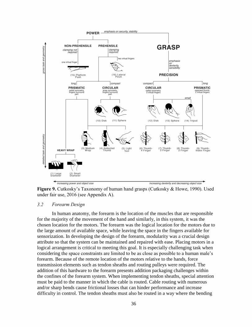
36
Figure 9. Cutkosky’s Taxonomy of human hand grasps (Cutkosky & Howe, 1990). Used
under fair use, 2016 (see Appendix A).
In human anatomy, the forearm is the location of the muscles that are responsible
for the majority of the movement of the hand and similarly, in this system, it was the
chosen location for the motors. The forearm was the logical location for the motors due to
the large amount of available space, while leaving the space in the fingers available for
sensorization. In developing the design of the forearm, modularity was a crucial design
attribute so that the system can be maintained and repaired with ease. Placing motors in a
logical arrangement is critical to meeting this goal. It is especially challenging task when
considering the space constraints are limited to be as close as possible to a human male’s
forearm. Because of the remote location of the motors relative to the hands, force
transmission elements such as tendon sheaths and routing pulleys were required. The
addition of this hardware to the forearm presents addition packaging challenges within
the confines of the forearm system. When implementing tendon sheaths, special attention
must be paid to the manner in which the cable is routed. Cable routing with numerous
and/or sharp bends cause frictional losses that can hinder performance and increase
difficulty in control. The tendon sheaths must also be routed in a way where the bending

37
is minimized by routing through the joint center of rotation of the universal joint of the
wrist.
The presented design is designed to for versatility and capability, so it serves
functions beyond containing the actuation for the hand portion. A fully articulated wrist
with the strength to be able to support the weight of the objects being grasped. It was also
desired that the forearm be able to attach rigidly to the upper body of a humanoid robot
platform, serving as a dexterous end effector.
Consideration was given not only to the physical architecture of the system, but as
well as the method of fabrication. Many designs are conventionally fabricated from
machined metal, which can be both time consuming and expensive, especially in the
event of changing design features. In the past several years with the increasing advances
and availability of rapid prototyping machines, robotics designers can iteratively create,
build, test, and redesign robots with very little turnaround. Because of this project’s
intended purpose as a research platform, rapid prototyping is a very advantageous
fabrication method. The platform presented in this publication, was created primarily
using an Objet Eden 260V 3D Printer. This particular printer is capable of printing in
several different materials. In this project, VeroWhite and VeroClear plastics were
chosen for the structural pieces, and TangoPlus rubber was also used. The design
presented is versatile enough to be adapted for the more traditional fabrication operations
of machining and casting, if so desired.
In order to maintain a compact human form factor, the use of tendon sheaths were
considered. A tendon-sheath is a method of force transmission where a cable tension
element is routed through a flexible outer tube. The ends of the outer tube can be fixed in
a desired location. This method of force transmission provides a higher level of flexibility
in actuator placement for a designer over other methods such as direct drive, gears, etc.
The robotic hand was designed with almost all of the joints being actively
actuated by cables pulling only in the flexion direction while springs force the joint to
extend back to the neutral position (here forth referred to as CAFSE for Cable Active
Flexion Spring Extension). Several other drive technologies were considered, including
single motor bi-directional cables (SMBC), dual motor bi-directional cables (DMBC),
and directly driving with motors placed at the joints (DD). Most human hand motions
only require flexion of the finger joints, as seen in the Figure 9, and CAFSE allows the
achievement of each of these grips. CAFSE was selected because it allowed the design to
be simplified while still achieving all the functionality required. However, four joints in
the hand require bi-directional motion and therefore do no use CAFSE: thumb rotation,
index finger ab/adduction, pinky finger ab/adduction, and wrist movement. The first three
are all driven by servos directly connected to the joint. The wrist, discussed in 3.2.6, is
unique because the joint has two degrees of freedom and therefore uses a pair of motors
connected to the hand using rods to produce motion. A comparative summary of the
actuation methods is shown in Table 3.
Table 3. A comparison of the potential robotic hand actuation methods.

38
CAFSE SMBC DMBC DD
Required
number of
actuators
= = - =
Size of motors
possible = = = -
Backlash = - - - Software
complexity = = - +
Actuating a joint using two cables, one for flexion and one for extension, can
most simply be achieved by using one or two motors per joint. In the SMBC method,
both cables would be connected to the motion of a single motor. Therefore, when the
motor moves, one cable is pulled while the other relaxes. Alternatively, the DMBC
method uses a separate motor to actuate the cables individually.
CAFSE overcomes several of the largest difficulties when using bi-directional
cables. In both SMBC and DMBC, twice the number of cables is required for each joints
which greatly escalates the complexity of routing the cables to the hand, especially
through the wrist where it is important to reduce volume to avoid interferences from wrist
motion. Both bi-directional methods can also suffer from issues with backlash due to the
need to continuously keep tension in each cable for a joint. Without this tension, the
finger would be susceptible to uncommanded motion and lag when changing motion
direction. Moreover, the cables can be over tensioned, in which case the non-active in a
motion (e.g. the extension cable during flexion movement) is constantly fighting the
active cable, reducing the max joint torque and increasing the current needed to maintain
the position. In SMBC, the two cables must be precisely tensioned through the
mechanical structure and changes in that structure, including cable stretch or component
wear, can degrade the tension over time. Because the cables are independently actuated,
DMBC requires that the motors be tightly calibrated and controlled to avoid lash or over
tensioning. CAFSE can be effectively zero backlash since the springs are always pulling
in opposition of the motor. Strictly speaking, the servo has internal backlash in its
gearing, the cables can stretch, and the Bowden cables can introduce backlash, but all
three of these are minimal and are counteracted by the springs. Calibration of joints is
also simple using CAFSE, as the most important datum is the first actuator position that
will cause joint motion.
Perhaps the greatest advantage of CAFSE over DMBC is the need for half the
actuators. The motors account for a large portion of the design weight and cost, both of
which are critical parameters to decrease in achieving the project goals. Each motor also
requires additional wiring and electronics which add volume and cost. Finally, more
actuators requires more sophisticated software, both in calibration and in active control.

39
The major advantages of CAFSE over DD are derived from having additional
space. A tendon-based hand allows the motors to be mounted in the forearm. This
provides more room to incorporate motors larger and higher-torque (assuming the same
types of motors were used) to be used than when employing DD. Furthermore, the space
in the forearm allows commercial motor controllers to be incorporated instead of custom,
smaller electronics that would drive up cost. Additionally, because of the limited space
for actuators at the joint, gearing with high reductions may be necessary to achieve
acceptable torque. This gearing adds additional backlash to the joint, which, as previously
discussed, is not an issue in CAFSE.
The CAFSE method does have several limitations as compared to other actuation
strategies. Because the finger is only actuated in one direction, outside forces can cause
uncontrollable extension motion. In order to cause flexion, the motor must also
continuously overcome the spring force which increases proportionally to the bend of the
joint. CAFSE places motors in the forearm and therefore could not be designed for the
hand to be used independently of the forearm, unlike DD which can have this capability.
Finally, the hand would be unable to perform any motions requiring extension, such as
flicking, unless the springs along are able to generate all the needed force.
In order to meet the goal of producing a low-cost platform, only commercial-off-
the-shelf (COTS) actuators were considered. Servomotors were selected due to their size,
price, form factor, versatility, and power density (Thayer & Priya, 2011). The built in
potentiometers for position control was also an attractive feature. Motor manufacturer
Hitec offers motors in a variety of torque output and sizes. Each motor is a self-
contained, ready to use unit that can be easily integrated into a platform, and replaced and
reconfigured easily if necessary. The selected Hitec motors and their specifications are
shown in Table 4. Selected extrinsic actuators.
Table 4. Selected extrinsic actuators.
Actuated DoF Model Torque at 6.0 V
(kg-cm)
Weight
(g)
Volume
(cm3)
Proximal/Thumb
Flexion
HS-
645MG 9.6 55 29.7
Medial-Distal Flexion HS-
225MG 4.8 27.94 16.8
Wrist HS-
7980TH 44 78.2 39.2

40
In designing the actuation of the wrist, a large range of motion and high strength
were desired for the wrist joint. To produce flexion/extension and radial/ulnar deviation
while minimizing the amount of motors and maintaining a compact form, a differentially
actuated spatial mechanism driven by two motors was designed. The motors are placed
adjacent to each other and each drives a linkage connected to the hand’s palm. The
motors can be driven individually or simultaneously, resulting in a degree of freedom
similar to that of a ball and socket joint.
The motors responsible for actuating each of the proximal joints of the four
fingers, as well as the three thumb flexion degrees of freedom are located behind the
wrist motors, in the upper chassis. These motors are Hitec HS-645MG which can output
9.6 kg-cm of torque when operated at 6V. These seven motors are organized such that
they line the length of the forearm, with their power cables routing out to the sides and
the servo shaft positions alternating from the preceding one, as seen in Figure 10b. This
arrangement was chosen because it was the most compact, and it allows the motors to be
independently inserted or removed from forearm without interfering with the other
motors.
The motors responsible for actuating the distal joints of the four fingers are
located on the underside of the forearm assembly, shown in Figure 10c. For this degree of
freedom, Hitec HS-225MG motors, rated at 4.8 kg-cm of torque when supplied 6V of
power, were selected. This cluster was located more towards the elbow, giving the entire
forearm a tapering shape similar to a human forearm. This also aids to move the center of
mass of the entire system towards the elbow, in order to decrease the moment arm on the
elbow of the robotic platform. The servo shafts face inwards to allow for the tendons to
route compactly along the center of the forearm. This lower chassis also contained the
HS-7980TH motor that drives the elbow rotation via a gear.
Figure 10. (a) Wrist rotation is accomplished through the use of two parallel motors
which can be driven separately or simultaneously, producing two DoF. (b) The upper
chassis contains the motors to actuate proximal DoF for each of the fingers and the

41
flexion DoFs for the thumb. (c) The four motors that actuate the distal DoF for the
fingers, along with the elbow rotation motor, are contained in the lower motor chassis.
In designing an extrinsically actuated hand, force transmission hardware must be
integrated in a manner which minimizes performance losses such as friction, but also
meets the goals of fitting into a compact humanlike form. In the design of the forearm, a
combination of tendon-pulley and tendon-sheath actuation was selected. Each of the two
transmission techniques has unique advantages over the other, but exclusively utilizing
one method over the other would not be optimal for this application. The finalized
physical arrangement of the motors allows for the motors to be removed independently
from each other, while fitting into a humanlike volume. A flexion tendon is anchored
onto a pulley which is rigidly attached to the servomotor shaft. Because the
proximal/thumb phalange flexion motors are intended to be removed from the top of the
forearm, the tendon routing is redirected to sides of the forearm system, seen in Figure
11c. Sharp bends in tendon-sheath routing must be avoided in design, because
performance is severely hindered by the high amount of distributed friction inside the
sheath. To redirect the direction of the force, a network of idler pulleys allow the tendons
to route along the length of the forearm, with lower friction loss than a tendon-sheath.
The tendon path and idler pulleys are inlaid into the side of the forearm to produce a
sleek design as well as to protect the tendons from external interference. At the wrist,
where the tendons must leave the forearm and enter the articulated wrist, the use of a
tendon-pulley system becomes complicated and impractical. Developing a pulley
network that decouples the tendon motion from the motion of the wrist would create a
great deal of added complexity to the design. To avoid this complication, tendon-sheath
transmission is utilized from the forearm to the palm of the hand. The tendon-sheaths can
be routed through the center of rotation of the wrist (Figure 11b), eliminating the chance
of interference from the wrist movements. The distal phalange flexion motors are located
on the underside of the forearm assembly. The orientation in which the distal motors are
arranged does not necessitate the use of a tendon-pulley actuation. Because the path to
the wrist is fairly straight forward and the distance is short, the tendon-sheath
arrangement is used, shown in Figure 11a.

42
Figure 11. (a) Pulley network which is routed through channels inlaid in forearm surface.
(b) Upon reaching the tip of the forearm, the tendons flow through the u-joint into the
hand via tendon sheaths which reduce friction and possibility of uncommanded finger
actuation. (c) Due to relatively straight path of tendons on the bottom of the forearm,
Tendon sheaths are sufficient to transmit the power of the distal motors.
The elbow attachment on the forearm allows the user to integrate the robotic hand
as an end effector manipulator on a pre-existing robotic system, shown in Figure 12. The
mechanism was devised to provide rotation at the elbow, in order to mimic wrist
pronation/supination. It is actuated by a HS-7980TH servo with a 1:1 gear ratio. The
driving gear is attached to the motor contained in the lower motor chassis. The driven
gear is rigidly attached to a machined hub using four screws. The system can be
integrated with any robotic platform using a matching hole pattern. As the motor
actuates, the forearm rotates itself about the rigid gear on the elbow.

43
Figure 12. The DASH hands attached to an 8 DoF robotic upper body system.
Much of the mechanism is contained within a structure of the elbow cap. The cap
joins with the upper chassis of the forearm with an interlocking geometry, similar to a
jigsaw puzzle piece. This allows the interlocking material to bear the cantilevered load,
rather than only the screws. When the cap is joined with the lower chassis, the tabs of the
elbow rotation motor is locked between the cap and the chassis. Screws from the cap pass
through the holes in the tab and thread into the chassis.
The minimize friction of rotation within the elbow cap a radial bearing was
selected and implemented. To withstand the axial loads in the elbow, a needle thrust
bearing is placed between the hub’s base and the elbow cap, and another is located
between the outside of the elbow cap and the elbow.
Figure 13 shows the exploded view of the elbow rotation mechanism.

44
Figure 13. The assembly of the elbow rotation mechanism is comprised of the following
components (from left to right): servo with two gear train, elbow hub, needle thrust bearing,
radial bearing, elbow cap, needle thrust bearing, elbow mounting bracket.
Additionally, the elbow cap serves as the location of the Pololu Mini-Maestro
servomotor controller, shown in Figure 14. The servomotor wires are routed in channels
down the length of the arm chassis, and attach to the connectors soldered to the
controller. This allows for the quick replacement of a defective motor during
maintenance.
Figure 14. The Pololu Mini-Maestro servo controller located in the elbow of the forearm.
The wrist design of the hand is based on the universal joint (U-joint), which
provides flexion/extension and radial/ulnar deviation, as well as allowing tendon-sheaths
to pass through. In the development of the wrist, several designs were prototyped and
evaluated. Each design allowed the tendons pass through the center of the U-joint to

45
ensure the least change in length of tendons as the wrist actuates. The first design
featured a central cross with a 20mm diameter hole in the center to allow for multiple
tendon sheaths to pass from the forearm to the palm without interference. This design
was to be assembled from a milled aluminum central cross, four milled aluminum
brackets, and four 3D printed plastic bushings. The major issue with this design was
potential interference between the palm of the hand with the supporting brackets if the
wrist was fully actuated to one extreme in either direction. In this special case, the
supporting bracket would be rotated in line with the hole in which the tendon-sheaths
enter the palm thus making unwanted contact with the tendon-sheaths. The next iteration
mitigated this issue by offsetting the axes of the U-joint by 12mm and decreasing the
bracket height to compensate for the offset. This allows the U-joint to be actuated in any
extreme position without making contact with the tendon system on the support brackets.
This new design is 3D printed to achieve the desired precision as well as produce its
irregular shape. Tensile strength became an issue in this demanding application, as 3D
printed plastic is brittle with a yield stress of 58 MPa. The final design uses the thickened
offset geometry printed in a stainless steel infused with bronze to produce a more robust
wrist joint at 682 MPa. This increased the tensile strength by a factor of 11 and still
allows for a large amount of tendons to pass freely through the wrist without interference
shown in Figure 15.
Figure 15. The evolution of the wrist U-Joint (a) in-plane wide u-joint, (b) split-plane
thin member u-joint, (c) split-plane thickened member u-joint, and (d) final split-plane u-
joint 3D printed in stainless steel and sintered bronze (Stevens, 2013). Reprinted with
permission (see Appendix A).
The actuation of the wrist is accomplished using a differential linkage mechanism
actuated by two motors. The U-joint serves as the junction of the palm and forearm and is
driven by linkage rods that connect at the wrist motors and extend to the palm of the
hand, shown in Figure 16. Each connection point of the linkage rods is a ball and socket
joint. In this mechanism, motors can be driven individually or together, to create a 2 DoF
motion that provides flexion/extension and radial/ulnar deviation. Actuated by two Hitec
HS-7980TH servomotors, which provide 44 kg-cm of torque each, the wrist is capable of
supporting a 2.56 kg load shown in Figure 17. This load exceeds the maximum
requirements established by the initial design specifications.

46
Figure 16. Differential actuation method provides 2 DoF in the wrist. Metal rods connect
the servo horns to the base of the palm with ball joints.
Figure 17. The wrist of the DASH Hand supporting a 2.56 kg weight (Stevens, 2013).
Reprinted with permission (see Appendix A).
The kinematics of the wrist were more challenging due to the differential
actuation method in the wrist. Typically most robotic systems are serial links in nature
with a dedicated actuated for each DoF, but such an arrangement would not be suitable in
this application because of the limited space. By having the motors arranged in parallel to

47
create the differential mechanism, they are able to be packaged in the humanlike form as
the design requires. The wrist design also allows for the tendons to pass through the
center of the wrist for smooth rotation and reduction in friction. Rotation matrices were
used to calculate the required angle of revolution of the two servo joints based on the
desired angle inputs of yaw, pitch and roll. The roll angle should be zero if the forearm is
not rotation about the elbow joint. The rotation matrices for roll, pitch and yaw are:
𝑅𝑜𝑡𝑎𝑡𝑖𝑜𝑛 (𝑥) = [1 0 00 cos 𝛾 −sin 𝛾0 sin 𝛾 cos 𝛾
]
𝑅𝑜𝑡𝑎𝑡𝑖𝑜𝑛 (𝑦) = [cos 𝜃 0 sin 𝜃
0 1 0−sin 𝜃 0 cos 𝜃
]
𝑅𝑜𝑡𝑎𝑡𝑖𝑜𝑛 (𝑧) = [cos 𝜃 − sin 𝜃 0sin 𝜃 cos 𝜃 0
0 0 1]
where the concatenation of the three rotations forms:
R = Rx×Ry×Rz
This final rotation matrix is multiplied by the neutral positions of palm side ball
joints to give the ball joint positions of JointR and JointL.
In this section, the design of the Dexterous Anthropomorphic Sensor-Driven
Hybrid-Actuation (DASH) hand is presented. The design focused on a hybrid approach
of combining intrinsic and extrinsic actuation in a human-like form factor. The
requirement of the hand and forearm maintaining biomimetic dimensions was enforced
during the design process. The entire system had to accommodate the required drivers,
motors, sensors and other electronics within the confined anatomical geometry.
Modularity of the fingers, palm, tendons and forearm were crucial to reduce the
maintenance and repair time. Robust positional feedback at the joints was necessary to
achieve accurate feedback without relying solely on the servomotor potentiometers.
Additionally, high power density ratios, high DoF, humanlike RoM, and low cost were
driving goals in the design. The final product seeks to be achieve a system that was
dexterous, sufficiently strong, and modular with a cost factor of at least one order of
magnitude smaller than any commercially available equally-capable systems. The final
design cost less than $1500 per hand system.
The design specifications for the humanoid hand and forearm required the
geometry to fit within the geometry of a 50th percentile adult male shown in Figure 18.
This constrained the design to be 193mm x 89.6mm x 42.6mm in length, width and
height of the humanoid hand. Humanlike digit lengths for the distal, medial, and proximal
phalanges were taken into consideration for each finger. DASH hand, shown in Figure

48
19, features the ring finger and index finger measuring 96 mm in length from fingertip to
proximal joint, while the pinky and middle finger measured 76mm and 101mm
respectively.
Figure 18. Human hand critical dimensions for the average male of 40 years of age
(NASA, 2000). Reprinted from NASA (see Appendix A).
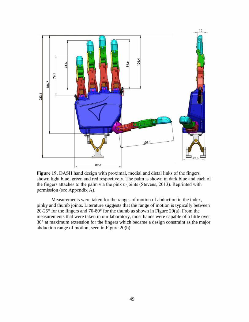
49
Figure 19. DASH hand design with proximal, medial and distal links of the fingers
shown light blue, green and red respectively. The palm is shown in dark blue and each of
the fingers attaches to the palm via the pink u-joints (Stevens, 2013). Reprinted with
permission (see Appendix A).
Measurements were taken for the ranges of motion of abduction in the index,
pinky and thumb joints. Literature suggests that the range of motion is typically between
20-25° for the fingers and 70-80° for the thumb as shown in Figure 20(a). From the
measurements that were taken in our laboratory, most hands were capable of a little over
30° at maximum extension for the fingers which became a design constraint as the major
abduction range of motion, seen in Figure 20(b).

50
Figure 20. (a) Abduction of index is 25° for the fingers and up to 80° for the thumb. (b)
Actual measurements for index and pinky abduction were measured closer to 31°. (c)
Final model shows the same range of motion was achieved. Reprinted from "Design and
Teleoperative Control of Humanoid Robot Upper Body for Task-driven Assistance" by
M. Stevens, 2013. Reprinted with permission (see Appendix A).
The addition of sensors in each actuated joint was desired for additional feedback
to assist in position control over the flexion motions. Secondly, the inclusion of sensors at
each actuated joint monitors the absolute joint position, rather than solely relying on the
motors’ potentiometers. This is highly desired in cases when the hand was obstructed by
a foreign object during extension movements. Additionally, absolute position feedback is
desirable over the motor position, because of the nonlinearities that result from tendon
actuation, such as friction and tendon elongation. Bend sensors shown in Figure 21 were
chosen over typical potentiometers or encoders because of the size, cost-effectiveness,
and resistance to mechanical degradation. The Flexpoint bend sensor is a conductive ink
based material laminated on a substrate and used to measure the deflection by change of
resistance. Essentially, the sensor is a variable resistor that is used to measure the
bending. These sensors are offered in a various lengths but are slim enough to fit in the
width of a typical human finger. They were attractive for DASH because they do not
occupy large area yet they can measure joint angles effectively.

51
Figure 21. The integrated Flexpoint bend sensors (Stevens, 2013). Reprinted with
permission (see Appendix A).
The kinematics of the hand were assumed to have a fixed-base joint located at the
center of the palm. Each of the links connecting the thumb were assumed to be in parallel
to this initial base joint. The MCP joints of the index and pinky fingers, as well as the
thumb’s CMC joint, can be approximated as a universal joint with two degrees of
freedom. Each of the other revolute MCP joints are 1 DoF. The motion of the proximal
interphalangeal (PIP) and the distal interphalangeal (DIP) are coupled via a four bar
linkage mechanism, to mimic the actual human finger movement.
Figure 22. Kinematic model of hand. Each blue cylinder represents a rotational degree of
freedom. The distal and medial joints are coupled for each of the fingers. The wrist is
driven by a differentially actuated mechanism design (Stevens, 2013). Reprinted with
permission (see Appendix A).

52
The extension movement of the joints relies on a passive actuation to provide a
counteracting force to return the joint to its neutral position. Spring steel was
implemented to provide this return force instead of torsional springs to allow for more
design freedom in sensor and tendon placement. In human anatomy, the motion of the
distal and medial is very closely coupled, so a four bar linkage mechanism was used to
couple the PIP and DIP flexion motions into one actuated motion, shown in Figure 23.
The tendon attaches to the medial phalange and coupled with a rigid rod, the distal
phalange actuates simultaneously with the medial phalange. This allows for a passively
actuated joint that still produces a natural human motion and eliminates the need for an
additional actuator.
Figure 23. Finger flexion of medial phalange coupled with distal phalange using a four
bar linkage mechanism (Stevens, 2013). Reprinted with permission (see Appendix A).
The abduction components of the humanoid hand play an important role in
performing different grip articulations. Of all the digits in the hand, the opposable thumb
is the most crucial abduction joint. It is the thumb that allows the formation of the c-
shaped-grip, power-grip, and the precision-grip. Widening the span of the finger allows
for the ability to grasp larger diameter objects in a “C-Shape” fashion. Precision grasps
allow for finer dexterity. The capability of these different grasp strategies into the design
allowed for versatility over multiple manipulation scenarios. After careful analysis, it was
found that the abduction/adduction of the middle and ring finger MP joints are less useful
for the different grasp strategies because they do not widen the grasp size but merely
make the hand look more realistic by providing equal spacing when abducting each of the
fingers in unison. This design choice to exclude these two DoF in the new hand design
was also motivated by the availability of space to package the actuators.

53
Figure 24. (a) Full finger flexion is possible with the use of 11 actuated degrees of
freedom. (b) Widening the grip size is accomplished with the three servos located in the
hand responsible for abduction. (c) The neutral position shown is the condition where
none of the motors were actuated (Stevens, 2013). Reprinted with permission (see
Appendix A).
Each individual finger is an endoskeletal structure consisting of four main pieces:
the knuckle, the proximal phalange, the medial phalange, and the distal phalange. The
majority of the components were designed to be fabricated using rapid prototyping in
order to allow for quick fabrication as well as to provide easily available replacement
parts during maintenance of the system.
The metacarpophalangeal (MCP) joints, or the knuckle of the index, middle, ring,
and pinky fingers were designed as a universal joint in order to mimic the flexion/
extension as well as abduction/adduction of the proximal phalange. The proximal
phalange rotates about X axis of the U-joint. For the index and pinky fingers, the entire
finger assembly rotates along the Y axis, which is joined to the palm, for
adduction/abduction. The middle and ring fingers do not ab/adduct, so the Y axis is
rigidly fixed to the palm. Much of the design of the knuckle component was derived as a
result of the decision to utilize bend sensors for joint position sensing. The bend sensor
was integrated as closely to center of the joint, in order to measure the angular position of
the phalanges. Additionally, the tendon responsible for actuating the medial phalange is
routed closely to the center of rotation of the MP. The MP universal joints were rapid
prototyped in bronze infused stainless steel to create a compact, yet strong part.
The proximal phalange structure rotates in flexion/extension about the MP joint.
This is accomplished using a tendon that is routed from the palm structure into a small
tunnel inside of the phalange. This tendon is terminated by pinning it into place using a
screw, allowing for quick installation and removal. The bend sensors extend from the MP
joint into the center of proximal phalange, seen in Figure 21. Also located in the proximal
phalange is another tendon tunnel through which the tendon that is responsible for PIP-

54
DIP actuation is routed through. A strip of spring steel is rigidly fixed at the MP joint,
and the strip extends over the top of the phalange. An attachable piece of plastic serves as
a sheath over the spring steel, allowing it to slide along the top of the phalange during
flexion and extension.
The medial phalange is attached to the proximal phalange by a 1.6 mm metal pin
at the PIP joint. Similarly to the proximal phalange, a single tendon is used for the flexion
of the joint and spring steel provides passive extension of the phalange. As previously
mentioned, the PIP and DIP joints are kinematically coupled via a four bar linkage
mechanism. The ground link of the mechanism is located at the PIP joint on the proximal
phalange. The distal phalange serves as the crank link, spanning from the PIP joint to the
DIP joint. A thin flat rod makes up the follower linkage and also connects to both the PIP
on the proximal phalange and DIP joint on the distal phalange. The distal phalange acts
as the coupler link to the mechanism. As the medial phalange’s tendon is pulled, the
phalange flexes and simultaneously drives the rotation of the distal phalange.
The DASH hand possesses a unique combination of extrinsic and intrinsic
actuation. The placement of the majority of the motors in the forearm allows for the
tendons to be routed through into the palm but also leaves a large volume available
within the hand. Motivated by the anatomy of the human hand, it was logical to place the
abduction actuators inside the hand, instead of the forearm (Figure 25). This arrangement
also eliminated the need for additional motors in the forearm, helping to maintain
anthropomorphic dimensions. The rotation of the thumb and the abduction of the index
and pinky proximal joints are driven with a bidirectionally driven, compact servomotor
which reduces the need of another motor and maximizes the space shown in Figure 25b.
The two motors responsible for driving the index and pinky abduction/adduction DoF
were connected to the U-joint via a linkage equipped with a ball joint. This allowed for
actuation of the flexion DoF of the joint without drastically interfering with the abduction
portion and vice versa. As seen in Figure 25c, the thumb was directly interfaced to the
servo without any other force transmission hardware or mechanism. Since each of these
motors was integrated into the palm and did not require a set of tendons passing through
the actuated wrist, it was confidently assumed that the servomotor position alone was
reliable. As a result, these DoF did not necessitate additional position feedback.

55
Figure 25. (a) the DASH hand is compared to a human hand to give a sense of
dimensional accuracy. (b) Intrinsic motor placement for abduction of the thumb, index
and pinky joints. (c) Palm design of intrinsic motors including the microcontroller and
tendon routing (Stevens, 2013). Reprinted with permission (see Appendix A).
Modularity was an essential design requirement to allow for repair and
modification with ease. This design goal led to the creation of an enclosed sensor housing
in the palm with a microcontroller that processed the joint positions of each of the
actuated fingers. Due to geometric constraints and number of analog pins needed, the
Teensy 3.0 microcontroller was chosen. The Teensy 3.0 packs 34 I/O, where 10 of which
are PWM channels and 14 are analog inputs, shown in Figure 26. An ARM Cortex chip
runs at 48 MHz and is powered by the micro USB. The entire device measures 35.5mm x
17.8mm and costs around $20. Overall, this device met the requirements of the
application in terms of size, speed, ease of use, cost and sufficient input for the 11 analog
bend sensors in the hand.
Figure 26. Arduino-based Teensy board measuring 35.5mm in width and 17.8mm in
length (Stevens, 2013). Reprinted with permission (see Appendix A).

56
In order to characterize the analog signal of each joint measurement, a voltage
divider was used to find the change in resistance for the angle shown in Figure 27. The
bend sensor can be approximated as a variable resistor with an increased resistance
proportional to its deflection. The optimal voltage divider, or the one that produces the
maximum sensitivity to the change in resistance, can be calculated by finding the
minimum and maximum resistance in order to optimize for the correct pull-down resistor.
The following voltage divider schematic shows how the sensor input would be
implemented.
Figure 27. Voltage Divider where Vin = 3.3V, R1= Bend Sensor, Vout = Analog Reading,
and R2 = fixed resistor.
The minimum and maximum resistance of the sensor for 0 to 90° was measured
with an ohmmeter to be 10-200 KΩ, respectively. Given the range of R1, the maximum
and minimum voltages that the board will read can be calculated as:
𝑉𝑜𝑢𝑡𝑚𝑖𝑛 =𝑅2 ∗ 𝑉𝑖𝑛
𝑅2 + 𝑅1𝑚𝑎𝑥
𝑉𝑜𝑢𝑡𝑚𝑎𝑥 =𝑅2 ∗ 𝑉𝑖𝑛
𝑅2 + 𝑅1𝑚𝑖𝑛
The derivative of the voltage ranges was taken with respect to R2 giving the
following equation:
By solving for zero and R2 as a positive value, the final equation becomes:
𝑅2 =
√−𝑅1𝑚𝑎𝑥2 ∗ 𝑅1𝑚𝑖𝑛 + 𝑅1𝑚𝑖𝑛
2 ∗ 𝑅1𝑀𝑎𝑥
√−𝑅1𝑚𝑎𝑥 + 𝑅1𝑚𝑖𝑛

57
which for the chosen bend sensors produces a fixed resistance of 39 kΩ. The
wiring diagram for the 4 voltage dividers in the flexion of the fingers is shown in Figure
28.
Figure 28. Simplified circuit diagram showing the first four flexion sensors with
cascaded voltage dividers (Stevens, 2013). Reprinted with permission (see Appendix A).
After producing the prototype of the initial design, grasping tests were conducted
to evaluate the kinematics. Previously mentioned, the Cutkosky’s Taxonomy (Cutkosky
& Howe, 1990) of grasps was used. The taxonomy is comprised of grasps of varying
levels of grasping power and precision, demonstrated on objects of varying size and
geometry. The potential dexterity of many high profile robotic hands, such as the
Robonaut hands, have been evaluated through the demonstration of the hands ability to
achieve the grasps in Cutkosky’s Taxonomy. The DASH hand was tested using a variety
of different objects, such as spheres, discs, and cylinders of varying diameters, seen in
Figure 29. The DASH Hand was capable of achieving 15 of the 16 grasps, demonstrating
a respectable amount of potential dexterity.

58
Figure 29. The DASH Hand demonstrating the grasps of Cutkosky’s Taxonomy,
accomplishing 15 of the 16 grasps.
The preliminary DASH hand was interfaced with a low cost glove design, which
is presented later in this paper. Because of the glove’s lack of finger abduction/adduction
and thumb rotation DoF, these were not controlled on the robotic hand. However, both
systems worked as intended. From a teleoperation standpoint, the thumb rotation servo of
the robotic hand can be adjusted by the user in the LabVIEW interface in order to meet
the need of the desired application.

59
Figure 30. The DASH Hand teleoperated by data glove.
In the testing of the initial DASH hand, the kinematic design of the hand was
found to be quite satisfactory and capable in manipulation. However, in the repeated use
of the hand, some shortcomings were revealed that required correction in order for the
system to function reliably as a platform.
The physical structure of the hand was found to be more fragile than initially
expected, shown in Figure 31. Thin walled features printed in the VeroWhite material
fractured after repeated use and in the occurrence of accidental collisions. The amount of
force being transmitted through the finger caused damage at the locations of the thin
1.6mm stainless steel pin joints, cracking the bearing surfaces of these revolute joints.
Additionally, the method of anchoring the tendons in the finger segments was susceptible
to failure when experiencing high amounts of transmitted force, resulting in the fracture
of the material surrounding the screw that secures the tendon.

60
Figure 31. Damage of the plastic structure of the DASH Hand. Damage prone areas
included the locations of the revolute pin joints, as well as the screws that secure the
tendons.
After repeated use, the spring steel used for providing the passive finger extension
would plastically deform, preventing the finger from returning to the fully extended
position, which can be seen in Figure 32. The small bend radius at the location of each
joint, also contributed to the spring steel deforming. This resulted in a diminished range
of motion for each finger, which consequently resulted in diminished performance in the
tendon driven actuation as the tendons rely on the quick extension response to maintain
tendon tension. The spring steel mechanism also provided a large amount of friction, as
the strip slides within a sheath on the phalange, which impedes the flexion motion.
Figure 32. The deformed spring steel after repeated use.
The design of the internal tendon paths led to issues with coupled joint movement,
as well as damage to the tendons due to friction. The tendon responsible for actuating the
coupled medial-distal phalange was routed through the MP joint, however was not routed
closely enough to the center of rotation of the joint. Because of this, when the proximal
phalange would move in flexion, the tendon for the medial-distal phalanges, would be
pulled as well, creating uncommanded movement. This coupled motion cannot be
corrected with the control system with the M=N actuation scheme. An N + 1 actuation
scheme would mitigate this issue but would require an extra actuator in the system,
increasing weight and complexity, thus a redesign is required for the fingers.
Finally, in most of the grasps found in Cutkosky’s Taxonomy, the fingers were
able to achieve the correct postures, however, security and stability of the grasps was
precarious. The slender structures of the fingers lacked substantial contact area with the
manipulated objects, making it impossible to envelope slender and small objects.
Additionally the smooth surfaces on the palmar surface of the hand effected grasp
security, as objects could slip out of grasp easily.

61
In this section, several design changes are presented that were made to the DASH
Hand design in order to address the shortcomings covered in section 3.4.3. The updated
design, maintains most of the basic dimensions, ranges of motion, and DoF as the DASH
Hand. In its current form, it lacks the abduction/adduction DoF for the index and pinky
finger, as well as the position sensors. These missing features can be easily be
reintegrated as a minor update.
The design of the revolute joints between the knuckles and phalanges was
changed from a shaft based joint to a shaft-less joint. In this design, the preceding finger
segment contains a radial bearing on each side and the succeeding segment features a
cantilevered hub on the outside surface that fits into the radial bearing, as shown in
Figure 33. The key advantage of this joint design over the previous one is that it allows
for the tendons to pass through the center of rotation of the joint (see Figure 34), which
will eliminate any coupling effect between the consecutive MP joint and the PIP- DIP
joints. With no shaft passing through the center of the whole joint, space is available for
components such as torsion springs to be integrated. Additionally, with the integration of
bearings, friction in the joints will be greatly reduced, allowing the spring elements to
perform the extension movement of each segment with less resistance.
Figure 33. An exploded view of the finger, showing the shaft-less joint design,
comprised of cantilevered hubs with radial bearings.

62
Figure 34. A cutaway view of the finger, showing the tendon channel of the proximal
phalange.
For each actuated finger segment, a pulley is integrated into the body of the
phalange, as seen in Figure 35. The tendon wraps around the pulley and is routed through
a channel that leads to a termination point. This design keeps the tendon constantly
tangent to the pulley, providing a constant joint torque.
Figure 35. The integrated pulley of the MC joint of the proximal phalange.

63
The integrated pulley diameters, servo horn diameters, and the motor torque are
the governing variables for the force output of the robotic hand. In the goal of
maintaining an anthropomorphic form, space constraints play a large role in the
determination of each of these, so pulleys in the MP joint and the PIP joints were
designed to be 18 mm and 15 mm, respectively. In future iterations, the pulley sizes can
be modified if so desired.
The internal tendon routing design was designed in order to reduce friction and
wear in the tendons evident in the initial design. This was accomplished through
providing the straightest and shortest path as well as minimizing the contact on the
tendon. The tendon to actuate the MCP joint leaves the sheath cable in the palm and
enters the knuckle component that is attached to the palm. This tendon is wrapped around
the integrated pulley of the proximal segment (see Figure 36a and Figure 36c).
As previously mentioned, the shaft-less joint design allows the tendons to pass
through the center of rotation of the joints of the proximal segments. To allow this, a 90
degree cutout is present in order to allow the finger segment to rotate without influencing
the movement of the tendon for the entire 90 degree ROM. This contact point between
the joint center and the tendon is a corner in reality, but is filleted in the design because a
sharp corner would result in friction, as well as cause wear on the tendon. The path
beyond the proximal joint center is a direct, straight path to the integrated pulley of PIP
joint. Inside the bounds of the finger, there are only two points of contact if the tendon is
taut: at the approximate joint center fillet and the groove of the integrated pulley of the
PIP joint, shown in Figure 36(b) and (d).
The tendon terminates by being wrapped around the integrated pulley and exiting
at a notch that is located at the 12 o’clock position at the top surface of the phalange. The
end of the tendon has a small metal nut tied to the end and the nut sits in the notch. The
motor horn position is adjusted to provide the correct tension on the tendon.

64
Figure 36. The tendon routing of both the (a) proximal and (b) medial phalange in the
fully extended as well as in the (c) proximal and (d) medial phalanges in the fully flexed
positions.
Due to the deformation and fatigue issues encountered in the use of strips of
spring steel, COTS torsion springs were selected to provide a more reliable means of
providing return force for the flexion movement of the fingers. A torsion spring is located
at the center of both the MP and PIP joints. In an effort to efficiently allocate space in
each finger phalange, the torsion spring is located in the center of the phalange’s
integrated pulley, as seen in Figure 35. In order to insert or remove the spring, a small
portion of the integrated pulley, secured by press fit, can be slid in and out of the shell of
the segment. This disassembly procedure is shown in Figure 37.

65
Figure 37. A press fit section of the integrated pulley is slid away to allow the torsion
spring to be released.
In the updated design, efforts were made to increase the durability of the hand, as
fragility of the initial DASH Hand design proved to be problematic. The shaft-less joint
design, presented in Section 3.5.1, offers significant robustness over the simple pin
design of the initial design. Wall thicknesses at critical locations such as the bearing
surfaces of the segments have been increased. The addition of more robust mechanical
limits at each joint restrict the movement of the segment to its prescribed range of
motion, protecting the joint in the event of the motor continuing to actuate beyond
desired (Figure 38).
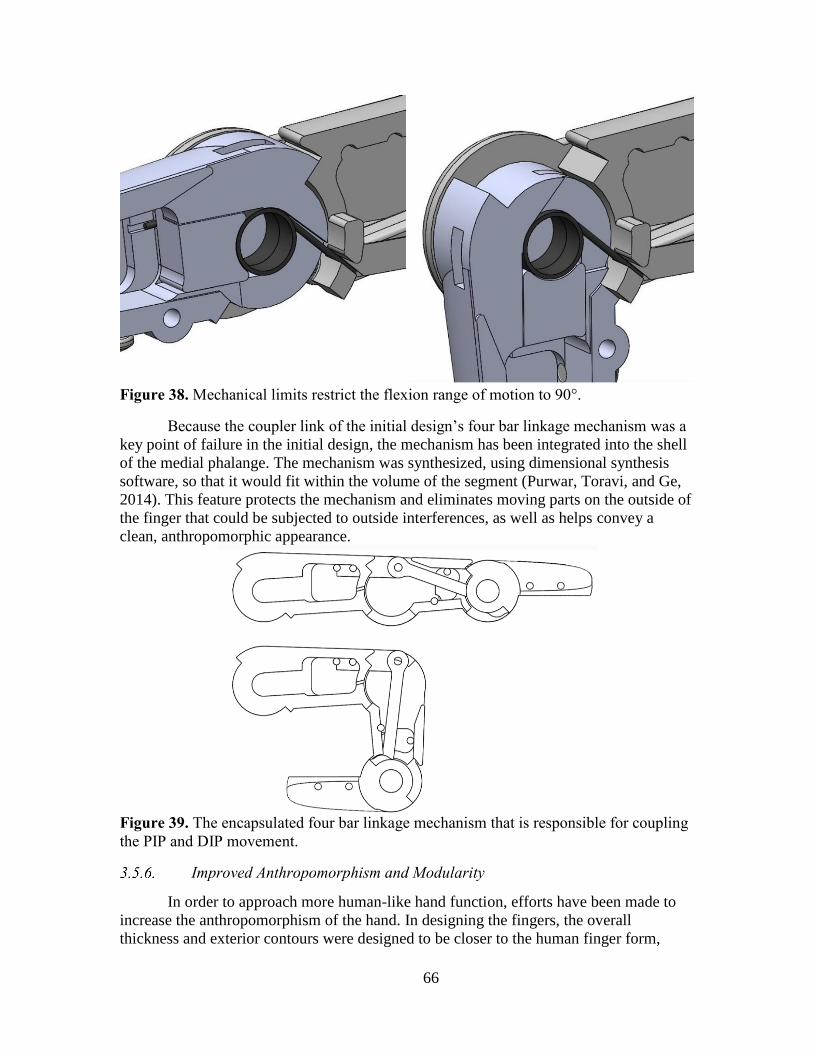
66
Figure 38. Mechanical limits restrict the flexion range of motion to 90°.
Because the coupler link of the initial design’s four bar linkage mechanism was a
key point of failure in the initial design, the mechanism has been integrated into the shell
of the medial phalange. The mechanism was synthesized, using dimensional synthesis
software, so that it would fit within the volume of the segment (Purwar, Toravi, and Ge,
2014). This feature protects the mechanism and eliminates moving parts on the outside of
the finger that could be subjected to outside interferences, as well as helps convey a
clean, anthropomorphic appearance.
Figure 39. The encapsulated four bar linkage mechanism that is responsible for coupling
the PIP and DIP movement.
In order to approach more human-like hand function, efforts have been made to
increase the anthropomorphism of the hand. In designing the fingers, the overall
thickness and exterior contours were designed to be closer to the human finger form,

67
allowing it to perform more closely like a human hand (Figure 40). The new form of the
fingers provides additional surface area to aid in the secure and stable grasping of objects.
The fingers have been fitted with removable rubber pads that attach on the palmar side,
where contact during grasping occurs. These pads are rapid prototyped on an Objet Eden
260V 3D printer using the flexible, soft Tango material. The rubber pads provide
additional gripping friction during grasps, reducing the chances of an object slipping out
of the grasp of the hand.
Secondly, the slightly larger thickness provides more space for sensors to be
incorporated at the discretion of the user. Each segment contains a hollow cavity inside,
which can serve as the location of future sensorization of the hand. The CAD file for the
finger module was designed in a “top-down” work flow, meaning that a master part file
can be changed using a few parameters in a spreadsheet, mainly the length and width of
each segment and the diameter of the joint. New features that may be conceived later on
can be applied easily to create an updated finger version.
Figure 40. The updated hand design, featuring more a more anthropomorphic form
which contributes to enhanced functionality and robustness.

68
Virtual testing of the design’s grasping ability was completed in SolidWorks
where the hand demonstrated the grasps featured in Cutkosky’s Taxonomy (shown in
Figure 41. The updated hand design was capable of performing all of the grasps in the
taxonomy, including the “small diameter” grasp that was unable to be performed by the
initial design of the hand. Based on this virtual modelling of the grasps, it is believed that
the increased thickness of the fingers, the more human-like form, and the rubber finger
pads, will greatly improve the performance by providing more secure grasps.
Figure 41. The updated hand performing the grasps of Cutkosky’s Taxonomy.
Due to the design changes made between the initial design and the updated one,
the bend sensors used for position feedback control were not integrated. Currently direct
feedback at the joints is not available. In the next phase of the hand, the addition of
analog Hall Effect sensors is desired, due to their low-profile, good reliability, and low
cost. A low-profile diametric magnet can be mounted at the joint center and the sensor

69
placed very closely by on the preceding phalange as shown in Figure 42. These sensors
provide contactless sensing. Alternatively, there is available interior space in each
phalange, so locating the sensor internally is also a viable option.
Figure 42. An analog Hall Effect sensor with magnet shown on a phalange prototype.
Additionally, the palm does not include the abduction/abduction motors,
eliminating two active DoF. In an incremental update, slight modifications of the palm
and the knuckles of the index and pinky fingers can be made to accommodate the
mechanism featured in the initial design of the DASH Hand.
Lastly, as was intended by the nature of the design, additional experimentation
with sensors and control systems is desired and anticipated. Users can augment the
capability of the hand as they see fit for their applications. In the next two following
sections, the creation of a tactile sensor is presented, as well as a method of impedance
control that minimizes the need for extra sensors.
The primary use of a human hand is to grip and manipulate objects, and robotic
hands seek to achieve the same goals. In order to achieve this, the later attempts to mimic
the methodologies of the former. In addition to controlling the joints on the hand to the
desired position, humans are able to control the amount of force applied to an object
using both the proprioceptive and somatosensory systems. The proprioceptive system is
the ability for the body to feel the relative position of the finger joints and the amount of
effort being exerted by the hand muscles. The somatosensory system is responsible for
the sense of touch, including the ability to feel pressure (both axial and sheer), texture,
vibration, temperature. Robotics are limited in the ability to mimic the somatosensory
systems because they are typically not completely covered in sensors, while the human
hand is covered in skin. If a force is applied to a point on the hand without a touch sensor,
the robot is unaware of the location or direction of the force. Additionally, many of the
sensors used on the robotic hands cannot sense both sheer and axial forces, leaving the
control system with an incomplete set of kinetic data. Therefore, many robotic systems
seek to mimic the proprioceptive system using impedance control.

70
Impedance control seeks to control the force of resistance to external motions that
are imposed by the environment. In other words, a joint will be commanded to a specific
position and velocity. If an external force is applied that resists the joint achieving this
goal, the impedance control attempts to alter force the joint applies against the external
force. Impedance control is typically implemented using kinematic and force/torque data.
Position sensors on the actuator and/or the joints of the finger are used to measure
kinematic data, and some robots use torque or force sensors on the joints to directly
measure the external forces.
Impedance control provides two primary advantages for this system: the ability to
control the force of the grasp or touch of an objects, and the ability to protect the hand
itself from damage caused either by grasping/pushing with too much force or from an
collisions with the hand. The former would provide the hand with greater dexterity. Both
advantages would be extremely useful when using the data glove to control the hand.
Since the user would primarily be controlling the hands using visual feedback, the
impedance control would allow the robot to compensate for user error or the lack of user
knowledge of the object being manipulated. Additionally, the force data could be
provided to the user in an effort to improve user performance.
With the goal of this robotic hand to be a low-cost system, hobby servomotors are
implemented as the actuators. These motors are operated in an open loop control system,
where the motor is provided a desired position which it then attempts to achieve using its
internal electronics. The user is not provided the actual motor position. Additionally, the
hand does not currently include any sensors to measure the position of the finger or wrist
joints. This means that the kinematic data is not available without additional hardware.
However, the current applied to the motor is proportional to the torque applied by the
motor. Therefore, the proposed method employs a ‘sensorless’ methodology, analogous
to sensorless FOC used in the control of permanent magnet synchronous motors using
only current sensors to negate the need for a rotor speed or velocity sensor (Akin,
Bhardwaj, and Warriner, 2013). This method uses only the current supplied to the
servomotor to interpolate any external forces being applied to the finger. No position
sensors would be added to the design. Although the servomotor has an internal
potentiometer, it cannot be accessed without significantly modifying the motor. Not
including position or velocity sensors provides several key advantages:
Less complex mechanical design.
Less expensive.
Simpler assembly due to fewer parts and the lack of need to calibrate each
position sensor.
The use of current sensors provides additional advantages. The chips used
to measure the servomotor current are physically small. The current sensing can also be

71
placed away from the actuator with the control electronics. This keeps the sensing
protected, both physically and electromagnetically. Finally printed circuit boards are
inexpensive and relatively easy to produce.
Despite the proposed method being simple and inexpensive, a number of
challenges also exist:
Lack of finger torque/force feedback.
Without directly measuring the force at the joint, the impedance algorithm
must interpolate the external forces applied to a finger from other information
instead of the true force.
Lack of finger position feedback.
Without measuring the position of the joint, the impedance algorithm cannot
determine if the finger is moving due to external, uncommanded forces.
Lack of servo position feedback.
o Cannot determine if a change in current is due to a motor action or
external forces.
o Cannot tell the direction that the motor is being moved.
o Attempting to perform a closed loop impedance control around a nested
closed loop system that cannot be observed.
o The only information on motor movement is the command to the
servomotor, meaning the time when the commanded position has been
achieved is unknown.
Single direction of controlled actuation.
Because the hand is tendon-based and uses springs to passively return the joints to
straight, the controller cannot impact the finger if the external force is applied in the
retract direction.
Current applied to the servomotor is only in one direction.
The servomotor’s internal circuitry determines the direction in which the current
is applied to the motor, but the current always flows in the same direction into the motor.
Therefore, the impedance controller cannot determine which direction the current is
attempting to make the motor move, only the amplitude.
Servomotor analog position controller.
The servomotor includes analog electronics that drive the motor to the desired
position. The dynamics of the analog controller are unknown, and without the motor
position from the internal position sensor it wouldn’t be useful.
To develop the sensorless impedance controller, the servomotor was initially
tested independently of the hand. The Hitec HS-645MG, which is one of the servomotors
used for many joints in the hand, was controlled by an Arduino Mega 2560. An Allegro
ACS712 Hall Effect current sensor was used to measure the current into the servomotor.
A schematic of the experimental setup is shown in Figure 43.

72
Figure 43. A schematic for the experimental setup of the ‘sensorless’ impedance
controller.
The impedance controller has two goals:
Devise a simple, tunable algorithm with parameters that hold real-world meaning.
Stable performance.
The impedance controller works by subtracting an offset from the commanded
position in an effort to decrease the applied motor effort. This offset is initially zero until
the measured current rises above the offset increase threshold. Then the offset begins to
increase as long as the current remains above the increase threshold. This moves the
finger away from its commanded position toward the fully retracted position. A second
threshold, the offset decrease threshold which is lower than the increase threshold, is used
to determine when the offset can begin to decrease. However, to reduce the joint limit
cycling, the current must remain below the offset decrease threshold for a set period of
time before the offset begins to decrease. This then moves the finger toward the
commanded position. The rate in which the offset increases is separately tunable from the
rate at which it decreases.
1. 𝜃𝑑𝑒𝑠 = 𝜃𝑐𝑚𝑑 − 𝜙
2. 𝜙 = {
𝜙𝑝𝑟𝑒𝑣 + 𝛼, 𝑖𝑓 𝐼 > 𝐼𝛼
𝜙𝑝𝑟𝑒𝑣 , 𝑖𝑓 (𝐼 < 𝐼𝛽) & (𝑇 < 𝑇𝛽)
𝜙𝑝𝑟𝑒𝑣 − 𝛽 , 𝑖𝑓 (𝐼 < 𝐼𝛽) & (𝑇 < 𝑇𝛽)
3. 𝜙𝑚𝑖𝑛 < 𝜙 < 𝜙𝑚𝑎𝑥
Where 𝜃𝑑𝑒𝑠 is the desired position that is sent to the servo after the impedance
control is applied, 𝜃𝑐𝑚𝑑 is the commanded servo position, 𝜙 is the offset from the
commanded position generated by the impedance control. 𝜙𝑝𝑟𝑒𝑣 is the pervious offset, 𝛼

73
is the offset increase per cycle, 𝛽 is the offset decrease per cycle, 𝐼 is the measured
current into the servo, 𝐼𝛼 is the current threshold to start increasing the offset, 𝐼𝛽 is the
current threshold to start decreasing the offset, 𝑇 is the time since the current decreased
below the decrease threshold, 𝑇𝛽 is the time threshold for how long the current must
remain below the decrease current threshold before the offset begins decreasing, 𝜙𝑚𝑖𝑛 is
the minimum offset (which is always zero), and 𝜙𝑚𝑎𝑥 is the maximum allowable offset.
At 7.3 seconds, an external torque was applied to the servomotor, as seen in
Figure 44. The current then increased, and the impedance controller began decreasing the
desired position (the position command sent to the servomotor). This continued until 9.3
seconds, when the external force was removed and the current decreased below the offset
decrease threshold. The desired position then increased until it 10.6 seconds, when it
again equaled the commanded position.
Figure 44. Experimental results of the impedance control of the servomotor.
There are numerous application domains that require human operators to regularly
expose themselves to dangerous situations and environments in the line of duty, such as
-20
0
20
40
60
80
100
120
140
0
10
20
30
40
50
60
70
80
90
100
6.7 7.7 8.7 9.7 10.7 11.7 12.7
Mea
sure
d C
urr
ent
(sen
sor
cou
nts
)
Serv
om
oto
r P
osi
toin
(d
egre
es)
Time
Impedance Control Experimental Results
CmdPos DesPos Current Counts

74
Explosive Ordinance Disposal (EOD) technicians, the agents tasked with containing the
leakage during the Fukushima disaster, and even the astronauts. All of these tasks could
ideally be performed by robots, and remove humans from harm’s way. However, current
control schemes for robotic automation have limitations as they cannot match a human’s
expertise, and thus humans must still risk life and limb to accomplish these dangerous
tasks. In recent years, teleoperated robots have increasingly become available, but still
lack full implementation into the wider world due to prohibitively high costs. If these
robotics and their controllers could be made affordable, there would be an increased
demand for human controlled robotics that function at the same level as a human
technician. This scenario of humans remotely controlling the robot with the same degrees
of freedom and range of motion as a human being will open many new possibilities.
A human-like robotic manipulator provides an excellent compromise between
strength and dexterity. However, the question that needs to be answered is “how to
control the robotic manipulator?” In its ideal form, a human hand is comprised of 22
degrees of freedom, though this is often reduced using coupled motions to more simple
versions such as the 16 degrees of freedom DASH hand, shown in Figure 45. However,
more complex versions of robotic hands have been demonstrated, such as the Shadow
Hand, which comprises of 22 fully actuated degrees of freedom.
Figure 45. The DASH Hand, shown in comparison with an adult male hand (Stevens,
2013). Reprinted with permission (see Appendix A).
When selecting a robotic controller the key concern is user familiarity. For
example, a computer mouse is a simple two degree of freedom controller that is
commonly utilized. Only, in some cases it requires specialized training for new users,
particularly children who have not been trained on those specific motor skills (Joiner,
Messer, Light, & Littleton, 1998). However, even with certain non-traditional mice that
are used for gaming or other technical purposes, the maximum degrees of freedom that
can be operated by one hand would be limited. Another controller option is a multi-axis
mouse or joystick, which has become popular for Computer Assisted Drafting (CAD)

75
programs. These controllers allow for an object to be rotated, panned, zoomed, and tilted
in 3-D space using a single hand. These tools require some training, as they are not as
familiar to the average user as a simple mouse, though they allow for more complex
control of a system.
While these tools have suitable features desired in a variety of applications, they
fail to take advantage of one of the key features of a human-like manipulator and that is
familiarity. Using a human-like hand for robotic teleoperation not only provides the
capability of using many human tools that are essential but it also allows for a very clear
association from the user to operate said manipulator as the user can use the manipulator
to effectively mimic their own methods of using tools. As such, it would be ideal to give
the user a controller that capitalizes on this inherent familiarity with a user’s own hand to
apply to the robotic manipulator.
A human-like user control interface could be developed using a data glove. A data
glove, which is also called a wired glove or sensor glove, is a fabric glove worn by a
human user that utilizes sensors to detect the positions of the user’s digits, and translate
them to an external program to be further used to control or record hand positions. Using
a data glove, it would be possible for a human user to effectively control a biomimetic
robotic manipulator by directly mimicking their own motions, creating a seamless
meshing of human teleoperative control.
One of the first data gloves invented was the “Sayre Glove,” in 1977 as part of
virtual reality simulations in an era where instrumentation and processing were in their
infancy. The Sayre Glove used an early version of fiber-optic sensors consisted of small
illuminated tubes whose light intensity varied based on the angle of bending in the finger
(Sturman & Zeltzer, 1994). Since this initial foray into sensing hand positioning, there
has been a keen interest in virtual reality applications in the 1990’s (Carlson, 2003),
which began to flow over into the commercial world, particularly with the Nintendo
Power Glove (Sturman & Zeltzer, 1994). However, due to the difficulties in reading and
processing analog signals, typical consumer applications remained limited due to
prohibitive costs for accurately sensing and reading information. In the end, data glove
technology ended as something of a gimmick.
Despite this initial setback into commercial realms, data glove technology
continues to be explored, but in a limited scope. From a brief survey of the available data
gloves, it becomes quickly apparent that typical data gloves are not affordable for the
average consumer, as noted in Table 5.
Table 5. Commercially available and research data gloves, with their respective sensing
methods, degrees of freedom, sensitivity, and cost.
Name Degrees of
Freedom(DOF)
Sensing Method Sensitivity Cost(USD)
5DT 5 Ultra 76 5 Fiber Optic < 1 degree $1,000
5DT 14 Ultra 76 14 Fiber Optic < 1 degree $5,500
76 (Fifth Dimension Technologies, 2005)

76
Cyber Glove 77 18, 22 Resistive 0.5 degree $10000-15000
Cyber Glove 2 78 18, 22 Resistive < 1 degree $12000-$18000
Cyber Glove III 79
18, 22 Resistive 0.5 degree $15,000
VMG Lite 80 11 Resistive <1 degree $600
DG5 VHand 2.0 81
10 Resistive <1 degree $400
P5 82 5 Resistive 0.5 degree $79.00
Didjiglove 83 10 Capacitive <1 degree $5000
Pinch Glove 84 4 Contact Switch Digital $2000
Dextrous Hand
Master 85
20 Hall Effect < 1 degree $5000-$10000
DataGlove 85 20 Fiber Optic 1 degree $5000-$10000
Power Glove 86 8 Resistive 3 steps $75
Color Glove 87 9 Color tracking Unknown $5 + optics
TCAS Glove 84 8, 11, 16 Resistive Unknown $7000+
As is evident from the majority of the listed data gloves, obtaining an accurate
data glove with more than 5 degrees of freedom is exceedingly expensive. In order to
properly control most dexterous operations for anthropomorphic robotic hands, at least
two degrees of freedom per finger must be independently measured and the thumb should
have an additional degree of freedom for adduction and abduction. While 104 discrete
data gloves have been developed for rehabilitation, entertainment, and virtual reality,
only 34 have the proper number of measured degrees of freedom for grasping, reliability
of not losing readings due to occlusion or other errors, and sensitivity for fine dexterous
control (around 1 degree of sensitivity). A majority of camera-based methods were not
included due to the risk of occlusion and loss of tracking, which would be catastrophic in
medical or industrial applications where constant tracking is a safety issue. These final
gloves have been detailed in Table 6, with details about their sensing technology and
degrees of freedom measured. The feasible gloves for robotics applications, with
considerations of cost, sensitivity and error, user friendliness, and implementation, are
ranked and reported in best-first ordered. Thus one of the objectives of this study was to
determine a methodology to create a data glove that (i) allows for at least 10 degrees of
freedom, (ii) is user friendly, and (iii) can be used by numerous hand sizes. The goal was
to achieve all of these features while keeping the costs of production below $250.
77 (Cyber Glover Systems, LLC, 2011) 78 (Tom's Hardware, 2005) 79 (Cyber Glover Systems, LLC., 2011) 80 (Virtual Realities, 2016) 81 (DG5 VHand 2.0, 2008) 82 (Cyberworld Inc., 2013) 83 (Didjiglove, 2008) 84 (Youngblut, Johnston, Nash, Wienclaw, Will, 1996) 85 (Caldwell, Andersen, Bowler, Wardle, 1995) 86 (Gardner, 1989) 87 (Lamberti, Camastra, Tecnico, Enrico, 2011)

77
Table 6. Feasible data gloves for robot control, based on degrees of freedom, sensitivity,
and reliability.
Glove Name Institution Sensing Technology
Degrees of
Freedom
Measured
VMG 30 88 Virtual
Motion Labs
Bending (Ambiguous)
Hand, Wrist 6DoF (IMU)
28
Tyndall/University
of Ulster Glove 89
University
College Cork
Resistive bending (Flexpoint)
3DoF Accelerometers
23
SIGMA 90 Sheffield
University
Resistive bending (carbon ink) 30
CyberGlove 2 91 Cyberglove
Systems,
LLC
Resistive bending 18, 22
CyberGlove Data
Glove 92
Cyberglove
Systems,
LLC
Resistive bending (thin foil strain gauge) 18, 22
MoCap Glove 93 Cyberglove
Systems,
LLC
Resistive bending 18, 22
SuperGlove 84 Nissho
Electronics
Resistive bending 10
5DT Data Glove
14 Ultra 94
Fifth
Dimension
Technologies
Inc.
Fiber Optics 14
Unnamed 95 National
Taipei
University
IMU 16
TU-Berlin
SensorGlove 96
Technical
University of
Berlin
Inductive length encoder
3D Spatial tracking
15
Unnamed 97 University of
Dong-Eui
Resistive bending
(Abrams Gentile Co)
11
HITEG-glove 98 University of
Rome “Tor
Vergata”
Resistive bending (Flexpoint) 15
88 (VMG 30) 89 (O’Flynn et al., 2013) 90 (Williams, 1997) 91 (Cyberglove Systems, 2009) 92 (Cyberglove Systems, 2007) 93 (Cyberglove Systems, 2010) 94 (Fifth Dimension Technologies) 95 (Lin, Lee, Hsiao, Yang, & Chou, 2014) 96 (Hofmann & Henz, 1995) 97 (Park, Bae, & Moon, 2009) 98 (Saggio, Bocchetti, Pinto, & Orengo, 2010)

78
Unnamed 99 Saliwanchik
Lloyd &
Saliwanchik
Resistive bending
(electrode resistance strain-related with
separating conductive rubber)
24
TCAS Glove 84 TCAS
Effects
Limited
Resistive bending 8, 11, 16
Unnamed 100 Mahidol
University
Conductive polymer strain gauges 10
PERCRO Data
Glove 101
Scuola
Superiore
Sant’Anna
(PERCRO)
Magnetic (Goniometric) 11
3D Imaging Data
Glove 102
University of
East Anglia
University of
Newcastle
upon Tyne
Magnetic
(inductive sensor in magnetic field)
11
Unnamed 103 Arthur D.
Little, Inc.
Hall effect 10
Humanglove 104 Humanwave Hall effect 20
SuperGlove Jr 105 Nissho
Electronics
Resistive bending 10
The Sensing
Glove 106
University of
Pisa, Italy
Resistive bending
(conductive elastomer, piezoresistive)
10
Unnamed 107 Stanford Resistive bending (strain gauge) 14
Unnamed 108 Modern
Cartoons, Ltd
Resistive bending 12
Unnamed 109 The Waikato
Polytechnic
Potentiometer
IR Deflection
22
Rutgers Master II
- New Design 110
Rutgers
University
Magnetic (Hall Effect)
Infrared reflective distance
15
Dextrous Hand
Master 84
Exos Hall effect 20
Unnamed 111 Pioneer
Electronic
Corporation
Ultrasonic or Infrared distance sensors 21
99 (Daum, Gunther, Husert, & Scherr, 2002) 100 (Tongrod, Lokavee, Watthanawisuth, Tuantranont, & Kerdcharoen, 2013) 101 (Portillo-Rodriguez et al., 2007) 102 (Su et al., 2003) 103 (Marcus, Lawrence, & Churchill, 1991) 104 (Dipietro, Sabatini, & Dario, 2003) 105 (Ishikawa & Matsumura, 1999) 106 (Tognetti, Carbonaro, Zupone, & De Rossi, 2006) 107 (Kramer, Lindener, & George, 1991) 108 (Walker & Baheshti, 2000) 109 (Iredale, Farrington, & Jaques, 1997) 110 (Bouzit, Burdea, Popescu, & Boian, 2002) 111 (Araki, 1996)

79
Rutgers Master II 112
Rutgers
University
Infrared reflective distance
Magnetic (Hall Effect)
Hand 6DoF (Polhemus)
21
Sensor Glove 2 113 University of
Tokyo
Rotary encoders 20
Z-Glove 114 Visual
Programming
Language
Research
Ultrasonic positioning/orientation
Optical flex sensors (Fiber optic)
20
DataGlove 114 Visual
Programming
Language
Research
Magnetic Position/orientation (Polhemus)
Optical flex sensors (Fiber optic)
20
Stringlove 115 Kyoto
University
Hospital
Magnetic (inductocoders) 22
Unnamed 116 National
Taiwan
University
of Science
and
Technology
Magnetic induction 10
Data Glove Input
System 85
University of
Salford
Hall effect 9
One of the most important factors when designing a data glove is determining the
method through which the finger positions will be sensed. In the past 30 years of research
on data glove development multiple methods for sensing have been investigated. The
most prevalent methods for finger joint tracking are visual, magnetic, and infrared spatial
tracking; direct measurement using resistive bend sensors, fiber-optic bend sensors, and
rotary encoders; and indirect tracking using magnetic inductance, Hall effect sensors, and
accelerometers.
The bulk motion of the hand, as well as the motion of the fingers, can be tracked
in the space of an operating environment. Once the coordinates and orientations of each
joint or link location are determined, forward and inverse kinematics can be used to form
the model of the hand in space or relative to the back of the hand.
112 (Gomez, 1997) 113 (Tsagarakis, Kenward, Rosander, Caldwell, & von Hofsten, 2006) 114 (Zimmerman, Lanier, Blanchard, Bryson, & Harvill, 1987) 115 (Kuroda, Tabata, Goto, Ikuta, & Murakami, 2004) 116 (Fahn & Sun, 2005)

80
The motion of the hand can be tracked in the operating volume while using an
external camera system and landmarks or discrete trackers on the hand. The cost
effective solution for commercial applications, such as the P5 glove (Lam, Zou, &
Komura, 2004), utilizes an infrared locating system for reflective markers on the data
glove. However, the resolution and repeatability of this method is lower than desired for
precision tasks. The simplest forms of visual tracking include using a single camera with
markers along the user’s hand to determine joint locations (Han, 2010) or using a
combination of a traditional camera and depth-mapping camera to give a 3D image of the
hand (Biswas, 2011). These markers can be discrete reflective trackers, such as with
VICON systems, or simple painted patterns around the glove the can be tracked using an
RGB camera (Wang & Popović, 2009; Lamberti, Camastra, Tecnico, & Enrico, 2011).
This method is popular because it is very inexpensive, only requiring a camera and
relatively simple software. Furthermore, the user is not tethered to any machinery,
allowing for mostly uninhibited movement. However, there are some distinct flaws in this
method. Namely, using markers along each joint of a human hand requires a significant
amount of time to place each marker in their designated spot. Furthermore, if any marker
falls off or becomes hidden from the viewing cameras, the software will not be able to
recognize the position of the hand. As such, this method is typically limited to academic
settings or entertainment due to the availability of large operating volumes, multiple
cameras, and several sizes of tracking markers that circumvents the problems of
occlusion and freedom of movement. However, usage of depth mapping and traditional
cameras is quickly becoming a more popular method of tracking joint locations. This
system has already been available on a larger scale for tracking human limbs in the
Microsoft Kinect (Microsoft, 2013; Zhang, 2011), while a smaller system called the Leap
Motion (Leap Motion, 2013) is available to consumers for the purpose of tracking hand
movements and gestures for computer user interfaces. Still, like traditional cameras, the
Kinect and Leap Motion are limited to what is visible in the camera’s field of view, and
as such, lacks portability for users and scale for industrial operations.
By attaching magnetic sensing coils to the hand, fingers, and arm, an external
magnetic field source can be utilized to triangulate the position and orientation of
landmarks in space. The most popular devices for magnetic tracking of objects in space
are the Polhemus (Burdea, Zhuang, Roskos, Silver, and Langrana, 1992; Polhemus
Navigation Sciences Division, 1987; Gomez, 1997; Hong and Tan, 1989) and Ascension
Flock of Birds systems (Kallmann & Thalmann, 1999; Oz & Leu, 2005). As mentioned
before, the spatial coordinates can be reduced to angular positions relative to the arm or
hand (Su, Allen, Geng, Burn, Brechany, Bell, & Rowland, 2003). However, similar
issues of portability and scale are limiting for widespread applications of magnetic
tracking systems. In addition, magnetic field tracking, especially in close proximity of
other tracking systems and the earth’s magnetic field, has inherent interference that may
need additional calibration and filtering.

81
For accurate and more sensitive photosensitive systems with affordable cost,
several optical sensor based data glove techniques have been suggested in recent years.
An optoelectronic joint angular sensor that consists of LED (light source) and photodiode
(detector) couple mounted to two continuous phalanges of robotic hands have been
considered to track the joint angles in data glove. When the finger joints are flexed, the
angle between LED and photodiode is changed, leading to changing irradiated light
intensity to the photodiodes. The angular displacement can be determined by the
measured photocurrent of the photodiodes in this system (Cavallo, De Maria, Natale, &
Pirozzi, 2009). This system was reported to have good repeatability and linearity, and low
noise of data signal with low cost for system construction. In similar way for an
alternative optical based data glove technique, a novel sensor based on optical linear
encoder have been introduced (Li, Chen, & Yeo, 2010; Li, Chen, Yeo, & Lim, 2011; Lim
et al., 2008). The optical linear encoder is a small size optical sensor that generates a
pulse signal as it detects an interruption to its reflective path. It consists of an infrared
emitter and a receiver couple in a single module. The infrared light from the emitter is
reflected off a reflective linear code strip, which is fabricated using a photo-plotter
engraved with parallel lines onto reflective linear code strips, and the reflected light is
detected by the receiver. When the finger joints are flexed, the light is reflected and the
receiver outputs two electrical pulses that are 90° out of phase. The out of phase electrical
pulses indicate the direction of travel of the fingers as the encoder moves over the linear
code strip. This technique enables capturing multi-finger motion in data glove device
with compact size, light weight, and low power consumption. Furthermore, good linearity
and accuracy of the digital output signal of optical linear encoder provide high
repeatability and reliability in both the gripped and flat hand positions.
Although direct sensing of the position of the fingers and hand is desired for
accuracy and limited processing, mechanical means for angular measurements typically
increase resistance for the operator and rely on mechanical phenomena that may lose
accuracy over time due to fatigue and wear. In addition, the housings for mechanical
sensing methods add additional weight to the glove, which increases strain on the user
with prolonged use. Therefore, indirect measurements allow lower strain on the user with
minimal reduction in accuracy.
Instead of spatially tracking the position of magnetic elements in space, magnetic
inductance and Hall Effect sensors can be used for tracking local magnetic landmarks.
Magnetic coils fixed on the hand can generate a local magnetic field at a prescribed
frequency, and sensor coils at the tips of the fingers can generate a voltage proportional to
the distance and angle from the generator (Fahn & Sun, 2010). In addition, by isolating
the magnetic signal at different frequencies the position and orientation from other
generators can provide feedback for adduction and abduction in the fingers. As with
magnetic spatial tracking, magnetic interference can add additional noise or biasing that
requires filtering and calibration.

82
As a compromise between low resistance on movement and the accuracy of direct
sensing, Hall Effect sensors are integrated into multiple unique sensor packages for data
gloves. The most popular application is the measurement of rotary joints in line with the
finger joints or in parallel in a linkage structure. By using magnets that are coupled with
the sensor but rotate in opposition during joint movement, the relative motion is sensed
and relayed in a feedback signal from the Hall sensor (Bouzit, Burdea, Popescu, & Boian,
2002; Gomez, 1997; Marcus, Lawrence, & Churchill, 1991). Similar to the magnetic
coils application, the relative motion of a Hall sensor on one link of a joint and a magnet
on the opposite link of a joint causes relative translation and rotation during finger joint
deflection, which in turn generates an electric signal (Caldwell, Andersen, Bowler, &
Wardle, 1995). As a non-resistive alternative to bending sensors, a Hall Effect sensor can
be placed at the base of a finger or a link with a proximal magnet attached to a flexible
element or string. Instead of the flexion of the finger changing the direction and distance
of a sensing element, the deflection causes displacement of the magnet due to the cable
stretching or pulling and in turn initiate a signal due to relative displacement (Kuroda,
Tabata, & Goto, 2004; Portillo-Rodriguez et al., 2007). The low cost and small size of
these sensors, with discrete sensors and magnetic elements embedded in the gloves,
enables low computation and setup time for sensing multiple degrees of freedom.
Due to the low cost, size, and weight of MEMS accelerometers and inertial
measurement units, one of the most popular sensing methods for data gloves are
gravitational and relative movement sensing. Static poses can be sensed by measuring the
distribution of gravitational acceleration between the two or three axes of the
accelerometer (Hernandez-Rebollar, Kyriakopoulos, & Lindeman, 2002; Lin, Lee, Hsiao,
Yang, and Chou, 2014; Perng, Fisher, Hollar, & Pister, 1999). This can be resolved to the
orientation of the sensor, and the relative orientation of the finger tips and links can be
calculated to find joint angles. Since it is low cost and low interference to integrate 3 DoF
accelerometers or full inertial measurement units, more sensors can be integrated on the
glove. This also means that fewer sensors can determine multiple degrees of freedom in
the hand due to physical constraints of link and joint positions. Many data gloves that
utilize inertial sensing have too few degrees of sensing to function as robot control
gloves, but they have enough readings to act as gesture identification data gloves.
However, data gloves that use alternative sensing methods integrate accelerometers,
gyroscopes, and IMUs in key locations such as the back of the hand to provide
redundancy in the sensing of other sensors and establish a coordinate frame for the hand
or forearm (O’Flynn et al., 2013).
Directly measuring the angle of the finger joints based on physical deflection is
the most reliable method for measuring finger position due to less computational
requirements for decoupling and isolating joint angles, as well as physical constraints to
the sensors. This enables onboard calculations and wireless data relaying to the home
station of the robotic devices, which greatly improves usability as well as generalizability
for different discrete applications in industry.

83
Rotary encoders or potentiometers in line with the joints or linked with joint
movement through mechanical apparatus greatly reduce the error, cost, electrical setup,
and computational power for correlation or acquisition. Rotary encoders directly measure
the rotation of a joint by optically sensing openings in a slotted disk, which in turn sends
a pulse from a series of photo diodes to a microcontroller that can be converted into a
fraction of a full rotation or a discrete position. Non-directional rotary encoders require
rotational reference calibration and a way to measure direction, while directional rotary
encoders include a direction and zero reference when rotated. Potentiometers also directly
measure the rotational location of a joint by rotating a wiper along a resistive path. Since
angular deflection changes the resistance of the potentiometer, both position and direction
can be determined with a single low-cost device. The response of potentiometers,
especially if manufactured with higher quality control, are typically linear and can be
easily correlated to rotary position. However, the physical wiper contact adds friction to
the movement of the joint, and the wiper can wear out over time. While these parts are
low cost and reliable, they still need mechanical fixtures to convert joint position into a
rotation of the measuring input axis, and repair of worn potentiometers decreases the
long-term usability of the sensors.
From the very onset of data glove technology, fiber optic bend sensors have been
used in data gloves, highlighted in the Sayre Glove, which was noted to be the first of its
kind (Sturman & Zeltzer, 1994). Fiber optic cables operate using thin glass or plastic
tubes to project light along the length of the wire with little or no losses over long
distances using total internal reflection along the interior of the cable. These cables have
become popular in recent years due to their applications for transmitting data over long
distances (Data Connect Enterprise, 2013). Fiber optics are also used for non-destructive
evaluation as they can detect small deformations. As the change occurs in radius along
the length of the cable there is modulation of the intensity at the end of the cable, which
can be detected by a simple photosensitive cell. The change in light intensity can be
further amplified using series of Fiber-Bragg gratings along the length of the wire located
directly on the platform subjected to bending. As these gratings are rotated or shifted
relative to the incoming light beam, the resultant change in light intensity is read by the
photosensitive cell.
Despite this being one of the oldest technologies used by the data gloves, this
method still remains popular for a number of reasons. Using specialized Fiber-Bragg
gratings allows for very sensitive readings of joint locations, while minimizing the
interference from outside sources, namely temperature dependence seen in some resistive
sensors. It entirely eliminates the electromagnetic interference at the location of the
sensor (Baek, Jeong, & Lee, 2002). As such, these sensors are the exclusive option for
researchers intending to perform studies nearby large magnets, such as those of an fMRI
used to assess a stroke patient’s motor skills. However, these sensors are quite expensive,
as producing a custom fiber optic sensor with the correct fiber-Bragg grating
specifications makes the sensors themselves expensive, while also requiring a suitably
sensitive photosensitive system to read varying light intensity from the sensors.

84
A third method that was selected for the design of the data glove in this study was
resistive based strain sensors. Resistive sensors are common, inexpensive, and simple to
use as they require a conventional circuit and small input voltage to return the relevant
data. They have a large variety of uses, which range from detecting small deflections in
structural elements of bridge (Kang, Schulz, Kim, Shanov, & Shi, 2006), to large
deflection purposes such as observing changes in finger position (Gentner & Classen,
2009). Regardless of the application platform, the operation of resistive strain sensors
remains the same. At their core, resistive sensors consist of conductive material that
changes its resistance due to the volumetric changes under external strain. Since the
sensor is placed above the finger joint, the deflection will be above the neutral axis and
initiate tension in the sensor. Resistivity rules dictate that resistance 𝑅 = 𝜌𝐿/𝐴, where 𝜌
is the resistivity of a specific material, L is the length of the element, and A is the cross
sectional area. Since resistivity is constant, resistance scales by L/A. As a material is put
under tension the length will increase and the cross sectional area decrease, thus
increasing resistance. The Poisson’s ratio of the material will dictate whether length or
cross sectional change will dominate in the behavior, and hence the strain characteristics
of materials as a sensor. When the sensor is placed in a voltage divider, the voltage drop
across the increasing resistance will increase and hence the output voltage between the
divider elements will decrease. Resistance matching of the divider resistor to the
operating range resistance of the sensor can tune the sensitivity and linearity of the sensor
output voltage. The voltage change can then be correlated with the magnitude of strain
observed by the sensor.
Figure 46. Flexpoint bend sensors, in 1", 2", and 3” lengths (Saggio, et al., 2014). Used
under Open Access.
One of the most common resistive based strain sensors are simple wired strain
gages that are used in various industrial applications. However, these sensors are
typically limited to relatively small strains, such as bending and stretching of metal
samples, which are very small (Kramer, Lindener, & George, 1991; Sturman & Zeltzer,
1994). These gauges can be adapted to larger strains by developing the shapes out of
polymer materials (Tongrod, Lokavee, Watthanawisuth, Tuantranont, & Kerdcharoen,
2013), graphene nanopaper (Yan et al., 2014), Velostat carbon film (Jeong, Lee, & Kim,
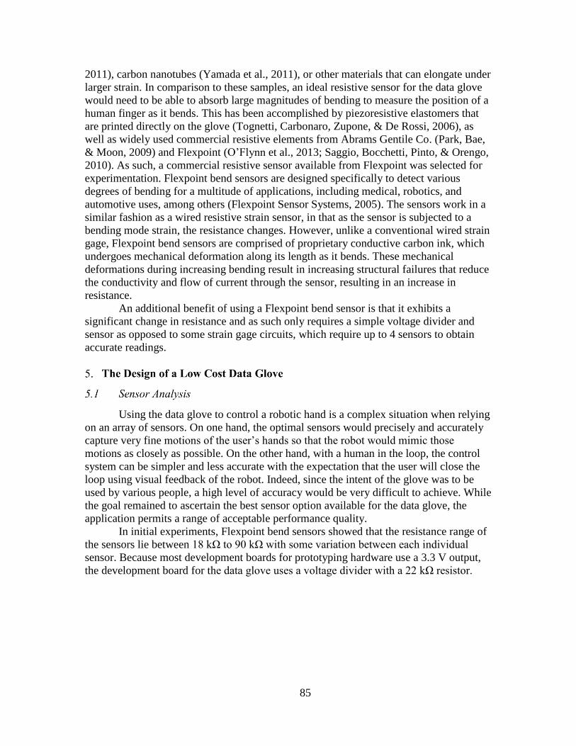
85
2011), carbon nanotubes (Yamada et al., 2011), or other materials that can elongate under
larger strain. In comparison to these samples, an ideal resistive sensor for the data glove
would need to be able to absorb large magnitudes of bending to measure the position of a
human finger as it bends. This has been accomplished by piezoresistive elastomers that
are printed directly on the glove (Tognetti, Carbonaro, Zupone, & De Rossi, 2006), as
well as widely used commercial resistive elements from Abrams Gentile Co. (Park, Bae,
& Moon, 2009) and Flexpoint (O’Flynn et al., 2013; Saggio, Bocchetti, Pinto, & Orengo,
2010). As such, a commercial resistive sensor available from Flexpoint was selected for
experimentation. Flexpoint bend sensors are designed specifically to detect various
degrees of bending for a multitude of applications, including medical, robotics, and
automotive uses, among others (Flexpoint Sensor Systems, 2005). The sensors work in a
similar fashion as a wired resistive strain sensor, in that as the sensor is subjected to a
bending mode strain, the resistance changes. However, unlike a conventional wired strain
gage, Flexpoint bend sensors are comprised of proprietary conductive carbon ink, which
undergoes mechanical deformation along its length as it bends. These mechanical
deformations during increasing bending result in increasing structural failures that reduce
the conductivity and flow of current through the sensor, resulting in an increase in
resistance.
An additional benefit of using a Flexpoint bend sensor is that it exhibits a
significant change in resistance and as such only requires a simple voltage divider and
sensor as opposed to some strain gage circuits, which require up to 4 sensors to obtain
accurate readings.
Using the data glove to control a robotic hand is a complex situation when relying
on an array of sensors. On one hand, the optimal sensors would precisely and accurately
capture very fine motions of the user’s hands so that the robot would mimic those
motions as closely as possible. On the other hand, with a human in the loop, the control
system can be simpler and less accurate with the expectation that the user will close the
loop using visual feedback of the robot. Indeed, since the intent of the glove was to be
used by various people, a high level of accuracy would be very difficult to achieve. While
the goal remained to ascertain the best sensor option available for the data glove, the
application permits a range of acceptable performance quality.
In initial experiments, Flexpoint bend sensors showed that the resistance range of
the sensors lie between 18 kΩ to 90 kΩ with some variation between each individual
sensor. Because most development boards for prototyping hardware use a 3.3 V output,
the development board for the data glove uses a voltage divider with a 22 kΩ resistor.

86
Figure 47. Voltage divider diagram. R1 is the sensor, and R2 is the static reference
resistor.
𝑉𝑜𝑢𝑡 =𝑅2
𝑅1 + 𝑅2∗ 𝑉𝑖𝑛
By applying the theoretical equation to the initially observed resistances, a change
from 1.72 volts to .78 volts accounting for a change of roughly 1 volt difference was
observed. This range could be further increased using an operational amplifier.
Having selected the sensor for the data glove, the next step was to consider how
many sensors were necessary in order to control a human-like hand. For this data glove,
10 degrees of freedom were decided to be necessary to successfully control the DASH
robotic hand and generate the desired grips in order to manipulate a number of tools.
These degrees of freedom include finger proximal flexion, distal-medial flexion, thumb
distal flexion, thumb medial flexion, and thumb proximal flexion. With sensors
measuring these joints, the data glove was capable of differentiating between crucial
grips, such as the power grip, precision pinch, and circular grip, which would encompass
a majority of typical objects to be handled during teleoperation. Several other degrees of
freedom were considered for the data glove but were not included due to difficulty in
implementation. These degrees of freedom include finger abduction, wrist
flexion/extension, and wrist ulnar and radial deviation.

87
Figure 48. Circular grip (left) and power grip (right) are ideal grips for a number of
teleoperative purposes. (Online Digital Education Connection, 2011). Used under fair
use, 2016 (see Appendix A).
Placing the sensors required selecting two distinct contact points near the joint in
question to track the desired degree of freedom. In typical data gloves, the sensors are
sewn into the fabrics, allowing the sensor to bend naturally about the joint. However, one
of the objectives of this data glove was to make it user friendly, and as such having
sensors sewn into the fabric would be difficult to replace or troubleshoot components in
the event of failure. Rather than try to fabricate a custom fabric glove, it was far more
efficient to find a method to retrofit an existing glove.
A variety of gloves were tested for both user comfort as well as adequacy for
mounting sensors. Among several key factors is how well the glove fits multiple users, if
the glove allowed full range of motion for the user, if the sensors would mount to the
glove fabric, and if the glove was comfortable. Some gloves, such as thick rubber kitchen
gloves, fit multiple users, allow for full range of motion, and support the sensors.
However, the glove is exceedingly uncomfortable for a user, due to the lack of

88
breathability of the rubber. Other gloves, such as a thin cotton glove, fit multiple users
comfortably, but the sensor was not suitably fixed to the glove, and would move from its
fixed base, causing inconsistent readings from the bend sensors.
Considering several options, the best glove for retrofitting into a data glove was a
battling glove from Under Armor. Consisting of a spandex and nylon weave with leather,
the glove is both comfortable and flexible enough to fit a variety of hands. The fingertips
were cut off from the glove to aid in comfort for the wearer as well as to allow for larger
hand sizes to fit into the glove by not limiting the glove based on finger length alone. The
sensors were attached using simple plastic dual lock connectors made by 3M (similar to
hook and loop fasteners), which allowed for sensors to be moved with respect to the
user’s fingers to provide a more ideal fit and better bending angles for the sensors, while
also providing the necessary stiffness to fix the sensors on the glove.
The other end of the sensor was slid into a small plastic slot. By folding the slot
into quarters and then gluing the resultant slot, the binder unit becomes an excellent
method to allow the sensor to bend, while also allowing the sensor to move axially along
the finger. However, some problems arose with this method for the proximal sensors, as
any slight abduction of the fingers would cause the sensor to buckle, creating
unintentional bending and thus creating error in the readings. However, a solution was
devised that involved using a wider slot, allowing the user to abduct their finger, while
leaving the sensor free of buckling. Using the same hook and loop connectors, these slots
were connected to the glove to allow for bending. Another potential issue is that the
sensors for the proximal digits overlap with the sensors for the PIP-DIP joints while the
user’s fingers are fully extended. To solve this, the PIP-DIP sensor was attached directly
to the slot to flex the proximal sensor, allowing the proximal sensor to pass beneath the
medial-distal sensor without causing any issues. With that system laid out, dual lock tabs
were attached directly to the glove fabric, eight two-inch sensors and three three-inch
Flexpoint bend sensors were attached to the glove.

89
Figure 49. Data schematic (above) and the physical data glove prototype (below), with
sensors attached to dual lock tabs, but without wires. Note that the proximal sensors are
free to slide beneath the distal sensors to prevent sensor buckling (Paluszek, 2013).
Reprinted with permission (see Appendix A).
Each sensor needs a voltage in and out to obtain a reading, requiring a total of 22
wires to run along the glove. To address concerns of wire clutter and tangles, it was
determined necessary to use a 25-port D-Sub connector to act as an intermediary between
the sensors and development board, which would allow the gloves to be independent of
the board and enable the gloves to be interchangeable with different boards.
A Maple microcontroller board was chosen, which appears to be an ideal option
for wiring a data glove. Powered by an STM32 processor, the Maple has 15 A/D ports
with 12 bit conversion, allowing for a resolution of 0.8 mV. Since the observed change of
Pl
astic Slot

90
voltage from a bent sensor is about 1V, the microcontroller is able to resolve roughly
1175 individual values. Furthermore, the Maple board costs only $45, consistent with the
goal of producing a cost-effective data glove.
Once the data glove prototype was built and wired, the next step was to determine
the effectiveness of the data glove from a usability standpoint. With the developed glove
and circuit the goal was to be able to observe a sensitivity of less than one flexion DoF in
each digit. The testing was conducted using a National Instruments data acquisition
system (DAQ) with a 16 bit A/D converter over a ±10 V range. This data acquisition
system provides a minimum sensitivity of 0.3 mV, which is even more precise than the
0.8 mV resolution of the Maple. Ideally, it will be possible to compare the data glove
sensor’s change in resistance (by measuring the output of the voltage divider) to the
actual current finger position. To accomplish this, a high-speed camera in tandem with
the DAQ was used. To successfully use the camera to track the joint angles, several
distinct marks were placed on the side of the data glove being filmed, seen in Figure 50.
Because the objective was to track the joint, three points were placed along the side of the
glove, near the finger. Using white acrylic paint, a dot is placed before the knuckle, at the
knuckle, and after the knuckle, which allowed an angle to be processed from the finger
positions. Then, using a high-speed camera filming at 60 FPS, simple flexing motion was
performed with the distal and proximal index joints.
Figure 50. Tracking points on the data glove. A net total of five points were needed to
accomplish tracking, having one dot along the palm of the hand, the proximal knuckle,
the proximal digit, the medial knuckle, and the medial digit (Paluszek, 2013). Reprinted
with permission (see Appendix A).
The next step was to find a method for synchronizing the camera frames to the
recorded data. Because the camera and voltage data were recorded separately, a new

91
method must be used to synchronize the two sets of data. To accomplish this, the circuit
had a small flip switch between the voltage divider and DAQ. By flipping the switch in
front of the camera, the exact frame can be determined where the voltage jump
corresponds to the switch being flipped.
Once the switch was flipped, the degree of freedom was gradually flexed from
fully extended to fully flexed, held for half a second, and then returned to the starting
position. Then, using a freeware image processing program ImageJ, each of the dots
along the data glove were manually marked in each frame to produce a series of
coordinates of the marked pixels. Then using these points to determine two lines and the
respective angle between them gives the angle of flexion. Using these two data sets,
correlation can be made between the angle of flexion and the voltage output from the
voltage divider.
Figure 51. Data Glove with tracking points (above) and link segment model (below).
Each dot is recorded as a series of x and y coordinate pixels, which were used to find the
relative positions of each link (Paluszek, 2013). Reprinted with permission (see Appendix
A).
P1
P2
P3

92
Using a linear fit to the data, a reasonably linear correlation between degree of
flexion and voltage output was visible, with a residual norm for the distal joint at 0.21
and the proximal joint at 0.13. While ideally a residual norm of 0.05 or fewer would be
preferable, there was little observed improvement in the fit by attempting higher
polynomial fits. Even using a 4th order polynomial to fit to the data, the residual norm for
the distal and proximal joints were 0.098 and 0.049, which did not account for enough of
an improvement to justify the increased difficulty of future attempts at calibration for a
user.

93
Figure 52. Proximal Angle vs. voltage with linear fit (above), Distal Angle vs. voltage
with linear fit (below) (Paluszek, 2013). Reprinted with permission (see Appendix A).
Of particular interest is the behavior of the proximal bend sensor. Upon observing
the data plot, there appear to be two different linear slopes, which transition after the 25-
degree flexion mark, seen in Figure 52. Upon further investigation, there was a change in
the bending of the sensor due to contact with the proximal knuckle. From 0-25 degrees of
flexion, the sensor is not in contact with the proximal knuckle, 25 degrees on the sensor is
in contact (Figure 53). This may explain the two distinctly different linear trends.
Figure 53. Data glove in the extended position (left) and at 25 degrees of flexion (right).
Note the sensor is not in contact with the proximal knuckle in the extended position, but

94
is in contact in the flexed position (Paluszek, 2013). Reprinted with permission (see
Appendix A).
However, this experimentation method was not without error. Due to the
flexibility of the glove around the user’s hand, the tracked points do not always
accurately reflect the true position of the user’s joint. Typically, marking points for
tracking assumes a rigid and unmoving marker, which is not possible with this glove.
Furthermore, because the points were tracked manually, some error is to be expected
during the process, especially since relatively small errors, such as selecting the edge of a
dot rather than the center, can significantly skew data. The tracking data presented here is
the result of several attempts, and appears to be adequate.
While the data glove appears to perform well for a low-cost solution, there are
several issues which should be accounted for in future versions. First and foremost, while
the design of fixing sensors to the outside of the glove made troubleshooting and
attaching sensors user friendly, it produced other concerns, such as sensor buckling and
external influences to the sensors. The proximal digit sensors would occasionally be
obstructed by the dual lock pads, resulting in the sensors producing a high resistance,
which would be interpreted as a high angle of flexion. Ideally, the next generation of this
glove would follow the methods of other data glove groups and use an inlaid sensor
design to mount the sensors directly onto to the hand, without the possibility for external
interference.
Furthermore, additional degrees of freedom on the data glove would be necessary
to track a user’s hand for other hand positions. Most importantly would be to add a sensor
to detect thumb rotation and abduction, which would allow for inclusion of a key or card
grip. Finger abduction sensors would also be able to take advantage of additional degrees
of freedom on the robotic hand described earlier. Also, it would be ideal to eventually
track wrist position on the data glove. This could be performed with IMUs, but this
would substantially increase the cost of the glove, which would conflict with the goal of
making the glove as cost efficient as possible. Thus, alternative solutions for sensing
should be explored.
Although the goal would be to teleoperate the system, the software development
in this study focused around implementation of the communication between the
microcontroller on the glove and the robotic hand via a shared computer. The Maple
microcontroller communicates with a LabVIEW application running on a computer via a
serial connection and the computer is also connected to the robotic hand via a second
serial connection. There are several necessary steps in order to go from obtaining a
voltage reading from the data glove’s sensors to controlling the robotic hand. First, the
computer must obtain and parse a string of values from the Maple board corresponding to
readings from the bend sensors, and then take these values to relay an angular position
interpreted from these values. These angular positions are then translated and relayed to
the robotic hand, which will then mimic these positions to give control using the data
glove. In Figure 54, the steps of the process to control the robotic hand is shown.

95
Figure 54. Simple flow chart explaining the process of obtaining, parsing and using
signals to control the robotic hand (Paluszek, 2013). Reprinted with permission (see
Appendix A).
Having obtained an array of 12-bit values from the Maple board, it is necessary to
translate these values into angular position that is interpreted from the user’s hand. The
previous section established that while a linear fit is not a wholly accurate approximation
of the response of the bend sensors with changes in finger position, but having a user
closing the loop permits this linear fit to be acceptable. As such, two points are needed to
create a linear fit, which can be most easily accomplished by using the start and end
position corresponding to 0° and 90° of flexion. While a human’s hand has variations in
degrees of flexion, 0° and 90° act as an approximation. This convention breaks each
degree of freedom into a fully flexed (90°) and fully extended position (0°). Because the
data glove encompasses proximal and distal flexion of both the fingers and thumb for a
total of 10 DoF, it would not be ideal to calibrate each individual position. Instead, there
will be a series of hand poses, which will be used to determine the fully flexed and
extended positions. The initial hand pose is the whole hand fully extended, also called
“Neutral”, which acts as the first value for both the proximal and distal sensors for the
fingers and thumb. In determining the additional pose, it is important to select sensors
whose motion will not impede or otherwise affect another sensor that is being recorded.
With this in mind, the next pose is titled “Distal Flex”, in which the index, middle, ring
and pinky distal medial joints are flexed, and the values from the corresponding sensors
are recorded. This is repeated for “Proximal flex”, in which the four fingers are flexed
Data glove mounted sensors are moved by user
Voltage from voltage divider sent to A/D port on Maple board
Maple sends voltage value in string to computer with Labview
Labview Parses bit values into hand positions
Labview converts hand positions into servo positions
Servos control hand

96
from the proximal joint. Because full range of motion in the thumb can impede the range
of motion of other fingers, these portions were split into another set of poses, called
“Thumb Distal” and “Thumb Proximal”. In our test for each of these poses, a pose can be
selected from a drop-down menu on the LabVIEW application. A button titled
“Calibrate” commands Labview to save the calibration values for the corresponding
sensors depending upon the drop down menu option that has been selected. This allows
the calibration options to be performed in any order, and allows for easy re-calibration.
This calibration process of the finger joints is shown in Figure 55, and the calibration
process for the thumb joints is shown in Figure 56.
Figure 55. Neutral Hand Position (top), distal finger flexion (middle), proximal finger
flexion (bottom) (Paluszek, 2013). Reprinted with permission (see Appendix A).

97
Figure 56. Thumb distal flexion (top) and thumb proximal flexion (bottom) (Paluszek,
2013). Reprinted with permission (see Appendix A).
Upon full calibration, Labview now has a 2x10 matrix of 12-bit integers, with one
column being the “Neutral” values, and the other being the corresponding values from the
flexed position calibrations. With these values, a linear calibration will translate the
values from the maple board into a value between 0 and 90, which will correlate to a
flexed and extended set of positions.
𝑃 =90
𝑉𝑓 − 𝑉𝑒(𝑥 − 𝑉𝑓)
where P is position, Vf is flexed bit value, Ve is extended bit value, and x is current sensor
bit value.
However, noise and variation in the sensor resistances can result in values
exceeding the calibration limits, so values were bound to a range of 0-90°. Once these
calibrations were completed, a series of bars on the front panel allowed the user to
visualize the output of the data glove following the prescribed conversion, while a
constant readout of the bit values coming from the hand prior to conversion allows for

98
additional troubleshooting. Once the calibration is complete, the user can push a button
labelled “Control” on the front panel, which will initialize the control of the robotic hand.
With this control setup, the user is able to determine whether or not the data glove is
sending the correct information to the robotic hand prior to actually controlling the hand,
reducing risks of sending unexpected or incorrect values and causing potential damage to
the motors or joints.
Table 7. Series of flexed and extended 12-bit values, observed bit values from the maple,
translated values from governing equations, and values after stopper program (Paluszek,
2013). Reprinted with permission (see Appendix A).
Extended Bit
Value
Flexed Bit
Value Bit Value In Translated With Stopper
2632 1687 2011 59.14 59.14
2985 1917 2556 36.15 36.15
2500 651 1232 61.72 61.72
1526 752 702 95.81 90
2125 887 2021 7.56 7.56
2118 917 2098 1.50 1.5
2226 1185 2326 -8.65 0
2359 821 2278 4.74 4.74
2265 966 1203 73.58 73.58
2011 455 1956 3.18 3.18
This full system allows usage of the data glove to control the robotic hand.
However, there have been instances of failures in the data glove, namely when sensors
become detached, or in cases where the motion of the sensor may be impeded. To deal
with these issues, the front panel of the controller can enable the individual degrees of
freedom of the robotic hand to be controlled through a series of LabVIEW slider controls.
This also allows a user to produce hand poses that are typically difficult be generated or
otherwise maintain. Furthermore, several degrees of freedom that are not tracked by the
data glove can be controlled using this method, including thumb rotation, pinky
abduction, and index abduction.
While the current data glove controller appears to be effective, there are numerous
improvements that could be implemented. Our studies in this paper focused around the
development of data glove, thus the data glove and the robotic hand were connected to
the same computer. Moving forward, in addition to glove development the focus would
shift toward teleoperation control, in which the glove could be in a different location than
the robot. This would provide a number of challenges, including latency and difficulty in
receiving visual feedback of the environment. Additionally, it would be useful to have the
ability to include readings from the fingertip sensors as part of the LabVIEW code to
provide feedback to the user. As this code would develop, semi-autonomous control

99
could also be developed, such as setting in force limits on the fingertips or creating
routines to maintain a grip on an object without input from a user.
Many of the data gloves designs found in literature have inherent difficulty in user
operation due to presence of wires, requirement of precisely placed markers and sensors,
and need for expensive hardware such as IMUs. The optical sensing gloves have been
shown to possess acceptable repeatability, linearity, accuracy, and resistance to
disturbance yet they also suffer from some pitfalls. The optical sensing based data glove
technique is based on light source and detector coupled system that is electrically wired
with a power source. However, this complicated system tends to increase not only weight
but also the cost of the data glove system. In order to overcome this complexity, we
introduce a novel wireless optical sensing technique based on stretchable
piezoluminescence (PZL) phenomena. The principle of PZL is described in the following
section.
The PZL effect refers to light emission phenomena induced by mechanical stress
enabling a high resolution dynamic strain sensing. The PZL phenomena has usually
appeared in coupling of energy conversion between electroluminescence effect (light
emission induced by electric field) and direct piezoelectric effect (electric field
generation induced by stress). For example, doped ZnS, a well-known PZL material, has
been used as an electroluminescent phosphor in displays and light sources and has
piezoelectric properties since it has asymmetric crystal structure. Once a mechanical
strain is applied to the doped ZnS, the electric potential is induced by the direct
piezoelectric effect leading to light emission by electroluminescence effect. This
phenomena is attractive for wireless control.
PZL ceramic materials are brittle under stress. To mitigate this obstacle, a PZL
rubber material can be fabricated where PZL micro-particles are simply mixed with the
elastomer polydimethylsiloxane (PDMS) solution along with the curing agent in a weight
ratio of 10:1. This is followed by stirring for 5 minutes to obtain a well-dispersed
mixture. Next, vacuum evacuation is carried out for 20 min to remove air bubbles in the
well dispersed PZL+PDMS solution in a vacuum desiccator. For solidification, the
PZL+PDMS solution is cured at 80°C for 30 min in a conventional oven. The PZL rubber
with high strain sensitivity and flexibility can be easily synthesized though this simple
fabrication process flow (Jeong et al., 2014; Jeong, Song, Lee, and Choi, 2013). The PZL
rubber generates light under strain without damaging (Figure 57(a) and (b)). Furthermore,
the PZL rubber can be applied onto any surface of materials. Figure 57(c) and (d) shows
PZL rubber applied on the cotton glove. As the wearer of the glove clenches their hand
into a closed fist, the material is strained and emits light.
Some of the key merits of the flexible PZL rubber is that it is easy to manipulate
color of a single light wavelength depending on the doping elements, and the intensity of
PZL is determined by strain and acceleration of the motion. In ZnS based PZL materials,

100
the doping elements and concentration of the doping change the defect induced energy
band structure in the materials. This defect engineering results in changing wavelength of
the light emission (e.g. Mn doped ZnS: Orange and Cu doped ZnS: Green or Blue) and
the PZL color can be simply manipulated by ionic substitutions. This is a very significant
capability for design of a wireless optical emission based data glove.
Figure 57. Piezoluminescent rubber (a) and (b) piezoluminescence under stretching-
releasing motion, (c) and (d) piezoluminescence rubber applied on cotton glove.
The PZL rubber patches emitting different colors can be mounted on the joints of
the data glove, then the degree of strain, motion speed, and coordinates of strained points
can be detected using photo diode arrays placed around the glove.
In camera based sensing, additional cameras must be set up in the work space to
expand the system’s sight in order to minimize the occurrence of occlusion. This adds
additional variables to the system and requires increased data processing. In methods
such as Kinect and Leap Motion, the system’s sight originates from a single device, also
increasing the chances of occlusion. In literature, photodiode arrays have been used for
image processing. In one of the prior studies, a camera was devised from a 30x40 array of
photodiodes, like the one shown in Figure 58 (Nayar, Sims, & Fridberg, 2015). In a
similar fashion, arrays of photodiodes can be fabricated and arranged in a three-
dimensional space, encompassing the workspace of the PZL based gloves, such as in
Figure 59. Such system is simple and the components to fabricate it are relatively
inexpensive as photodiodes cost around few cents per unit. Resolving a kinematic model
from the multiple arrays can be accomplished through transformation calculations by
using the measurements from the active photo diodes like a coordinate system. Because
the light emission center of PZL materials usually exhibits a single wavelength, the photo
diode arrays can distinguish color signal at each joint with extremely low noise. This
wireless data glove system can provide a simple structure of glove for better mobility,
zero power consumption of light source, and low cost compared to other sensing method.

101
Figure 58. A photodiode array designed to function as a camera (Nayar, et al., 2015).
Reprinted with permission, © 2015 IEEE (see Appendix A).
Figure 59. Photodiode arrays arranged to sense the PZL light emission.
In testing the PZL rubber for data glove, it will be necessary to create a patterned
glove design on which the PZL rubber can be applied in a calculated geometry. A typical
off-the-shelf glove such as the cotton glove shown in Figure 57(b) and (c) is much too
loose fitting, where the entirety of the glove fabric can slide along the length of the hand.
A design to isolate the discrete area of the measured joint is necessary. We propose three
basic concepts of glove design a shown in Figure 60(a)-(c). The first PZL based glove
concept is a glove that has segments of PZL rubber placed directly at the hand joints to be
measured, shown in Figure 60a. This design concept leads to one of the simpler designs
for the glove apparatus itself. However with the placement of PZL elements, the sensing
procedure to detect the location, and intensity of the PZL’s light emission may be more
complicated. In the second glove concept, seen in Figure 60b, the majority of the PZL
elements are consolidated to the dorsum of the hand. The PIP joint positions are
measured indirectly in this concept. The PZL elements are remotely located on the
dorsum and the PIP joint motion is transmitted to the PZL element via tension elements,
such as a tendon-sheath transmission, which displaces the element linearly. The MP joint
102
positions can be measured either directly or indirectly like the PIP joint positions. The
advantage of this arrangement is that the consolidation of the PZL elements to a general
location may aid in easier visual tracking. However, there is a trade-off as the glove
design does become more complex with the integration of the tension elements. The last
glove concept introduces a method of color coding each joint. As mentioned previously,
it is possible to create the PZL rubber with different color emission. Because of the vast
amount of colors that can be created, each joint can be represented by its own color,
simplifying the need to interpret which joint is being activated. Color coding can be
applied to both of the other two concepts as well. This concept is shown in Figure 60c.
Figure 60. (a) A data glove design with PZL rubber element located at each joint,
providing direct joint measurement. (b) A data glove design where the majority of the
PZL rubber elements are located on the dorsum of the hand and the motion of the PIP
joints are transmitted through tension elements. (c) A data glove concept featuring PZL
elements of unique colors to easily distinguish the different joints of the fingers. Color
coding can be used in the other concepts as well.
The contactless, wireless sensing capabilities of PZL-based materials can also be
utilized in the development of force and position sensors, as well as a hybrid sensor types
where PZL capabilities can be combined with a conventional sensor.
We propose the concept of a hybrid sensor that combines the PZL rubber material
with another more conventional sensor. In the context of data glove designs, a PZL
rubber coating can be applied to the resistive bend sensors discussed earlier in this paper.
A designer might find the versatility of a hybrid sensor type desirable because one
function of the sensor may be more favorable in certain instances. For example, in a
primarily PZL-based data glove design, there might be a DoF that is more difficult to
sense using PZL, so the designer can utilize the resistive bend sensing functionality to
mitigate the issue of occlusion. Conversely, in applications where wired sensors are
predominantly used, the PZL functionality can be activated in order to reduce the number
of wires on the system.
In literature, there have been low cost optical sensing technology based on source-
sensor combinations, such as LEDs coupled with photodiodes. These sensors offer an
inexpensive method of sensing. Similarly in principle, the luminescence of a PZL
material can serve as the light source in an optoelectronic sensor type. This would

103
eliminate a wired source component, the LED, simplifying the sensor design. In
literature, many of the sensor designs involved attaching an LED and photodiode onto a
compliant structure. Forces applied to the compliant structure create a relative
displacement, where the distance between the LED and photodetector is altered, resulting
in a change in the photodiode’s output. In the proposed method, a compliant structure can
be coated with the PZL rubber or cast from it, and the photodiode will be able to detect
the luminescence intensity to determine the force. Additionally, the PZL rubber can be
suited for tactile sensing applications. A PZL based taxel can be fabricated comprising of
a photodiode array on a flexible PCB which is covered in a layer of PZL based rubber. As
pressure is applied to the sensor assembly, the PZL rubber layer will deflect and
illuminate. The intensity and the location of the pressure can be sensed by the photodiode
array.
The PZL material is a promising choice towards demonstrating a novel wireless
data glove technique with high sensitivity and low cost. However, many challenges still
remain for practical deployment. In the current generation of materials, the PZL is
invisible under a bright external light because of its low light emission intensity. To
realize enhanced brightness, here we discuss the mechanisms of the PZL phenomena and
suggest future design approaches. The PZL phenomena is the coupling between
electroluminescence and piezoelectricity as mentioned above. For example, in Cu-doped
ZnS (ZnS:Cu), ZnS wurtzite crystal has piezoelectricity which generates electric potential
under strain. The ZnS:Cu particles includes a defect states with trapped electrons in the
donor state and trapped holes in the acceptor state. Once a mechanical strain is applied to
the ZnS:Cu, the conduction and valence band of the ZnS are tilted due to the piezoelectric
potential. Owing to the internal electric field in ZnS:Cu, the trapped electrons are
detrapped into conduction band and then recombination occurrs to Cu induced acceptor
level with light emission (Figure 61).
The PZL intensity is mainly contributed to by the electron-hole recombination
process. Based upon the operating mechanism of PZL, we can suggest two different ways
to enhance the intensity. First, the enhancement of piezoelectricity of PZL materials
increases detrapping and recombination rate of the electrons resulting from the increased
internal electric field. Since, the PZL materials usually have low piezoelectric
coefficients (e.g. longitudinal piezoelectric coefficient (d33) of ZnS: ~3.3 pC/N), the
strain induced internal electric field is not sufficient to excite all trapped electrons.
Second, rising number of trapped electrons in the defect donor level can increase the
electron-hole recombination pairs leading to high PZL brightness. The concentration of
trapped electrons usually generated by anion defects in the PZL materials can be
increased by doping and intrinsic vacancies. The doping elements and their concentration
in the PZL determines not only number of trapped electrons but also color. Therefore,
optimization of the defect structure of the PZL materials through defect engineering is
one of the ways to obtain highly enhanced PZL light.

104
Figure 61. Schematics of energy band structure and driving mechanisms of PZL ZnS:Cu
material.
The PZL phenomena is dependent on only change of strain which provides some
obstacles in its application. In cases where the material is not experiencing a change of
strain, such as if the joints of a finger are stationary while holding a grasp or if the hand is
in a neutral position (all finger joints extended), then there will be no piezoluminescent
response. The sensing will not be completely continuous and the finger will be assumed
to be in the last recorded position from the previous measurement. It would be similar in
principle to an incremental encoder. Another obstacle with the PZL for a data glove is the
lack of directional information. The PZL emits light proportional to strain, but the
response will be the same if that strain is in tension or contraction. With only amplitude
of the change without directionality, methodologies or mechanisms would have be
implemented to determine if the finger was bending or straightening. Incremental
encoders overcome this by using a pair of offset sensors to interpret direction. Using
multiple PZLs for each joint may provide a similar solution.
In this paper, a combined and comprehensive survey of anthropomorphic robotic
hand design and data glove technology has been presented. Both technologies are often
designed and implemented independent of each other. However, combining the two
technologies in implementing practical teleoperated applications has great potential for
assisting personnel’s in medical, military, and domestic environments. Treatment of two
technologies together will lead to platform specific metrics that will guide the further
development of joint technology. Continuous advancement in the technology of
actuators, sensing, and controls is necessary in order to improve the design, control, and
precision of robotic hand and data gloves. A thorough review of the design of low-cost
data glove and robotic hand hardware was presented, in order to accelerate the
development of technology across multiple spectrum of application platforms.
In our efforts of exploring low-cost data glove based teleoperation of
anthropomorphic robotic hands, a robotic hand-forearm platform, the DASH Hand, was
developed at a cost of approximately $1500. The hand-forearm system possesses a total
of 16 active DoF, maintains a human-like size and appearance, and can be integrated as
the end effector for a humanoid robot platform. All the characterization was conducted on
a 3D printed robotic hand. The robotic hand had low cost COTS bend-sensors for

105
position feedback control. Thorough testing led to few iterations of the hand with
continued improvement in the functionality and reliability. A unique impedance based
control method was introduced allowing the system to sense external resistance on the
fingers. This provides the hand with feedback during grasping and senses external forces
from the environment. This control technique requires minimal sensing hardware which
results in low cost method of control.
In pursuit of a cost-effective and intuitive method of teleoperative robotic hand
control, a low-cost data glove was designed and fabricated. The resulting design was a 10
DoF glove that cost around $300, making it a fraction of the cost of available data glove
products. The design’s sensing was accomplished through the use of COTS resistive bend
sensors which are reconfigurable to accommodate a wide range of user hand sizes.
Through careful analysis, the sensors of the glove were found to be adequately linear and
sensitive for robotic hand control. Using the glove, teleoperation of the DASH robotic
hand was successfully performed. With continued development, both devices have great
potential for adoption by early stage researchers and graduate students in the robotics
field.
With much of the development of the low-cost data glove and robotic hand
hardware complete, both systems can be improved to offer enhanced functionality and
reliability to pursue exciting applications. Increasing the number of sensors on the data
glove, such as adding an additional thumb DoF as well as abduction/adduction DoFs, can
greatly enhance its ability to control high DoF robotic hand systems. Additional
experimentation in teleoperation of the DASH robotic hand will be pursued, to explore
new applications for robotic hands and control methods. In this paper, a new iteration of
the DASH Hand was presented, where the design changes served to address issues with
the initial prototype but to also expand its functionality as a research platform. Some
features of the initial prototype must be reintegrated to the current version such as the
index and little finger abduction/adduction DoF as well as absolute position sensing in
the joints. Further sensorization of the robotic hand is anticipated to enable the system to
more adeptly perform manipulation tasks. Additionally, further development of the novel
PZL data glove concept will be pursued, to create a wireless, unpowered data glove. The
PZL material also possesses great potential to be implemented in the creation of new
hybrid technology sensors, and force and position sensing.

106
Atwell, C. (2012, Oct. 15). Are gesture-sensing interfaces set to replace your mouse
and keyboard? ms digit and leap motion say yes. Retrieved from
http://www.element14.com/community/community/news/blog/2012/10/15/are-
gesture-sensing-interfaces-set-to-replace-your-mouse-and-keyboard-ms-digit-
and-leap-motion-say-yes
Ahn, K., & Yokota, S. (2005). Intelligent switching control of pneumatic actuator
using on/off solenoid valves. Mechatronics, 15(6), 683-702.
Akin, B., Bhardwaj, M., & Warriner, J. (2013). Sensorless Field Oriented Control of 3-
Phase Permanent Magnet Synchronous Motors. Texas Instruments, Application
Notes.
Akyürek, E., Kalganova, T., Mukhtar, M., Paramonov, L., Steele, L., Simko, M.,
Kavanagh, L., Nimmo, A., & Huynh, A. (2014). Design and development of
Low cost 3D printed ambidextrous robotic hand driven by pneumatic muscles.
Aleotti, J., & Caselli, S. (2006, May). Grasp recognition in virtual reality for robot
pregrasp planning by demonstration. In Proceedings 2006 IEEE International
Conference on Robotics and Automation, 2006. ICRA 2006. (pp. 2801-2806).
IEEE.
Araki, Y. (1996). Three Dimensional Coordinates Input Apparatus. US Patent
5512919.
Atzori, M., Gijsberts, A., Heynen, S., Hager, A. G. M., Deriaz, O., Van Der Smagt, P.,
... & Müller, H. (2012, June). Building the Ninapro database: A resource for the
biorobotics community. In 2012 4th IEEE RAS & EMBS International
Conference on Biomedical Robotics and Biomechatronics (BioRob) (pp. 1258-
1265). IEEE.
Bae, J. H., Park, S. W., Park, J. H., Baeg, M. H., Kim, D., & Oh, S. R. (2012, October).
Development of a low cost anthropomorphic robot hand with high capability. In
2012 IEEE/RSJ International Conference on Intelligent Robots and Systems
(pp. 4776-4782). IEEE.
Baek, S., Jeong, Y., & Lee, B. (2002). Characteristics of Short-Period Blazed Fiber
Bragg Gratings for Use as Macro-Bending Sensors. Applied Optics, 41(4), 631-
636.
Bekey, G. A., Tomovic, R., & Zeljkovic, I. (1990). Control architecture for the
Belgrade/USC hand. In Dextrous robot hands (pp. 136-149). Springer New
York.
Belter, J. T., & Segil, J. L. (2013). Mechanical design and performance specifications
of anthropomorphic prosthetic hands: a review. Journal of rehabilitation
research and development, 50(5), 599.
Bennett, D. A., Dalley, S. A., Truex, D., & Goldfarb, M. (2015). A multigrasp hand
prosthesis for providing precision and conformal grasps.
Berka, R., & Goza, S. M. (2012). Telerobotics on Robonaut2. Journal of the Robotics
Society of Japan, 30(6), 565-567.
Biswas, K. (2011). Gesture recognition using Microsoft Kinect. Automation, Robotics
and Applications(ICARA) (pp. 100-103). Wellington: IEEE.

107
Bohren, J., Rusu, R. B., Jones, E. G., Marder-Eppstein, E., Pantofaru, C., Wise, M.,
Mosenlechner, L., Meeussen, W., & Holzer, S. (2011, May). Towards
autonomous robotic butlers: Lessons learned with the pr2. In Robotics and
Automation (ICRA), 2011 IEEE International Conference on (pp. 5568-5575).
IEEE.
Bouzit, M., Burdea, G., Popescu, G., & Boian, R. (2002). The Rutgers Master II - New
design force-feedback glove. IEEE/ASME Transactions on Mechatronics, 7(2),
256–263.
Bridgwater, L. B., Ihrke, C. A., Diftler, M. A., Abdallah, M. E., Radford, N. A.,
Rogers, J. M., Yayathi, S., Askew, R.S., & Linn, D. M. (2012, May). The
robonaut 2 hand-designed to do work with tools. In Robotics and Automation
(ICRA), 2012 IEEE International Conference on (pp. 3425-3430). IEEE.
Burdea, G., Zhuang, J., Roskos, E., Silver, D., & Langrana, N. (1992). A portable
dextrous master with force feedback. Presence: Teleoper. Virtual Environ.,
1(1), 18–28.
Butterfass, J., Grebenstein, M., Liu, H., & Hirzinger, G. (2001). DLR-Hand II: Next
generation of a dextrous robot hand. In Robotics and Automation, 2001.
Proceedings 2001 ICRA. IEEE International Conference on (Vol. 1, pp. 109-
114). IEEE.
Butterfass, J., Hirzinger, G., Knoch, S., & Liu, H. (1998, May). DLR's multisensory
articulated hand. I. Hard-and software architecture. In Robotics and
Automation, 1998. Proceedings. 1998 IEEE International Conference on (Vol.
3, pp. 2081-2086). IEEE.
Caffaz, A., Casalino, G., Cannata, G., Panin, G., & Massucco, E. (2000). The DIST-
hand, an anthropomorphic, fully sensorized dexterous gripper. IEEE
Humanoids.
Caldwell, D. G., Andersen, U., Bowler, C. J., & Wardle, A. J. (1995). A high power /
weight dexterous manipulator using ’ Sensory Glove ’ based motion control and
tactile feedback. Trans Inst MC, 17(5).
Cannata, G., & Maggiali, M. (2005, December). An embedded tactile and force sensor
for robotic manipulation and grasping. In 5th IEEE-RAS International
Conference on Humanoid Robots, 2005. (pp. 80-85). IEEE.
Carlson, W. (2003). A Critical History of Computer Graphics and Animation.
Retrieved April 10, 2013, from Ohio State Department of Design:
http://design.osu.edu/carlson/history/lesson17.html
Carrozza, M. C., Suppo, C., Sebastiani, F., Massa, B., Vecchi, F., Lazzarini, R., ... &
Dario, P. (2004). The SPRING hand: development of a self-adaptive prosthesis
for restoring natural grasping. Autonomous Robots, 16(2), 125-141.
Casley, S., Choopojcharoen, T., Jardim, A., Ozgoren, D., Onal, C., & Padir, T. (2014).
IRIS Hand Smart Robotic Prosthesis.
Cavallo, A., De Maria, G., Natale, C., & Pirozzi, S. (2009). Optoelectronic joint
angular sensor for robotic fingers. Sensors and Actuators A: Physical, 152(2),
203-210.
Chalon, M., Wedler, A., Baumann, A., Bertleff, W., Beyer, A., Butterfaß, J., ... &
Landzettel, K. (2011, May). Dexhand: a space qualified multi-fingered robotic

108
hand. In Robotics and Automation (ICRA), 2011 IEEE International
Conference on (pp. 2204-2210). IEEE.
Challoo, R., Johnson, J. P., McLauchlan, R. A., & Omar, S. I. (1994, October).
Intelligent control of a Stanford JPL hand attached to a 4 DOF robot arm. In
Systems, Man, and Cybernetics, 1994. Humans, Information and Technology.,
1994 IEEE International Conference on (Vol. 2, pp. 1274-1278). IEEE.
Che, D., & Zhang, W. (2010, November). A humanoid robot upper limb system with
anthropomorphic robot hand: GCUA hand II. In International Conference on
Social Robotics (pp. 182-191). Springer Berlin Heidelberg.
Cheng, G. (Ed.). (2014). Humanoid Robotics and Neuroscience: Science, Engineering
and Society. CRC Press.
Choi, B., Lee, S., Choi, H. R., & Kang, S. (2006, October). Development of
anthropomorphic robot hand with tactile sensor: SKKU Hand II. In 2006
IEEE/RSJ International Conference on Intelligent Robots and Systems (pp.
3779-3784). IEEE.
Cipriani, C., Controzzi, M., & Carrozza, M. C. (2011). The SmartHand transradial
prosthesis. Journal of neuroengineering and rehabilitation, 8(1), 1.
Cohen, D., & Halgren, E. (2004). Magnetoencephalography. In B. S. G. Adelman,
Encyclopedia of Neuroscience. Amsterdam: Elsevier.
Cutkosky, M. R., & Howe, R. D. (1990). Human grasp choice and robotic grasp
analysis. Dextrous robot hands, 1, 5-31.
Cyber Glover Systems, LLC. (2011). Cyber Glove III. Retrieved Sept 2011, from
Cyber Glove Systems web site:
http://www.cyberglovesystems.com/products/cyberglove-III/overview
Cyberglove Systems (2007). CyberGlove Data Glove User Guide.
Cyberglove Systems (2010). MoCap Glove.
Cybergloves Systems. (2009). CyberGlove ® II. http://www.cyberglovesystems.com
Cyberworld Inc. (2013). P5 - Virtual Reality Data Glove. Retrieved Sept 2011, from
Cyber World Store web site:
http://www.cwonline.com/store/view_product.asp?Product=1179
Dalley, S. A., Bennett, D. A., & Goldfarb, M. (2012, August). Preliminary functional
assessment of a multigrasp myoelectric prosthesis. In 2012 Annual
International Conference of the IEEE Engineering in Medicine and Biology
Society (pp. 4172-4175). IEEE.
Data Connect Enterprise. (2013). Fiber Optics: The Basics of Fiber Optic Cable.
Retrieved Feb 18th, 2013, from Data-Connect Web Site: http://www.data-
connect.com/Fiber_Tutorial.htm
Daum, W., Gunther, T., Husert, J., & Scherr, P. (2002). Data Glove. US 2002/0075232
A1.
Dautenhahn, K., Nehaniv, C. L., Walters, M. L., Robins, B., Kose-Bagci, H., Mirza, N.
A., & Blow, M. (2009). KASPAR–a minimally expressive humanoid robot for
human–robot interaction research. Applied Bionics and Biomechanics, 6(3-4),
369-397.
Davis, S., Tsagarakis, N. G., & Caldwell, D. G. (2008, December). The initial design
and manufacturing process of a low cost hand for the robot icub. In Humanoid

109
Robots, 2008. Humanoids 2008. 8th IEEE-RAS International Conference on
(pp. 40-45). IEEE.
Dillmann, R. (2004). Teaching and learning of robot tasks via observation of human
performance. Robotics and Autonomous Systems, 47(2), 109-116.
Dipietro, L., Sabatini, A. M., & Dario, P. (2003). Evaluation of an instrumented glove
for hand-movement acquisition. Journal of Rehabilitation Research and
Development, 40(2), 179–189.
Dipietro, L., Sabatini, A. M., & Dario, P. (2008). A survey of glove-based systems and
their applications. IEEE Transactions on Systems, Man, and Cybernetics, Part
C (Applications and Reviews), 38(4), 461-482.
Dollar, A. M., & Howe, R. D. (2010). The highly adaptive SDM hand: Design and
performance evaluation. The international journal of robotics research, 29(5),
585-597.
Englehart, K., & B., H. (2003). A Robust, Real-Time Control Scheme for
Multifunction Myoelectric Control. IEEE TRANSACTIONS ON
BIOMEDICAL ENGINEERING, 50(7), 848-854.
Fahn, C. S., & Sun, H. (2010). Development of a fingertip glove equipped with
magnetic tracking sensors. Sensors, 10(2), 1119-1140.
Fahn, C., & Sun, H. (2005). Development of a data glove with reducing sensors based
on magnetic induction. In Industrial Electronics, IEEE Transactions on (Vol.
52, pp. 585–594).
Ficuciello, F., Palli, G., Melchiorri, C., & Siciliano, B. (2011, September).
Experimental evaluation of postural synergies during reach to grasp with the
UB Hand IV. In 2011 IEEE/RSJ International Conference on Intelligent Robots
and Systems (pp. 1775-1780). IEEE.
Fifth Dimension Technologies. (2005). 5DT Data Glove 5 Ultra. Retrieved Sept 2011,
from Fifth Dimension Technologies web site:
http://www.5dt.com/products/pdataglove5u.html
Fifth Dimension Technologies. 5DT Data Glove Ultra Series.
First steps: ISS's 'Robonaut' gets new legs for Easter. (2014, April 21). RT. Retrieved
from https://www.rt.com/news/iss-robonaut-new-legs-760/
Fishel, J., Lin, G., & Loeb, G. (2013). BioTac® Product Manual. SynTouch LLC,
February.
Flexpoint Sensor Systems, Inc. (2005). About the Bend Sensor. Retrieved Dec 2011,
from Flexpoint flexible sensor systems:
http://www.flexpoint.com/companyInfo/bendSensor.htm
Fukaya, N., Asfour, T., Dillmann, R., & Toyama, S. (2013, November). Development
of a five-finger dexterous hand without feedback control: The TUAT/Karlsruhe
humanoid hand. In 2013 IEEE/RSJ International Conference on Intelligent
Robots and Systems (pp. 4533-4540). IEEE.
Fukaya, N., Toyama, S., Asfour, T., & Dillmann, R. (2000). Design of the
TUAT/Karlsruhe humanoid hand. In Intelligent Robots and Systems,
2000.(IROS 2000). Proceedings. 2000 IEEE/RSJ International Conference on
(Vol. 3, pp. 1754-1759). IEEE.
Gaiser, I., Schulz, S., Kargov, A., Klosek, H., Bierbaum, A., Pylatiuk, C., Oberle, R.,
Werner, T., Asfour, T., Bretthauer, G., & Dillmann, R. (2008, December). A

110
new anthropomorphic robotic hand. In Humanoids 2008-8th IEEE-RAS
International Conference on Humanoid Robots (pp. 418-422). IEEE.
Gantz, B., Turner, C., Gfeller, K., & Lowder, M. (2005). Preservation of Hearing in
Cochlear Implant Surgery: Advantages of Combined Electrical and Acoustical
Speech Processing. Laryngoscope, 796-802.
Gardner, D. L. (1989). Inside story on: The power glove. Design News, 45(23), 63.
Gazeau, J. P., Zehloul, S., Arsicault, M., & Lallemand, J. P. (2001). The LMS hand:
force and position controls in the aim of the fine manipulation of objects. In
Robotics and Automation, 2001. Proceedings 2001 ICRA. IEEE International
Conference on (Vol. 3, pp. 2642-2648). IEEE.
Geng, T., Lee, M., & Hülse, M. (2011). Transferring human grasping synergies to a
robot. Mechatronics, 21(1), 272-284.
Gentner, R., & Classen, J. (2009). Development and evaluation of a low-cost sensor
glove for assessment of human finger movements in neurophysiological
settings. Journal of Neuroscience Methods, 178(1), 138-147.
Gomez, D. H. (1997). A dextrous hand master with force feedback for virtual reality.
Rutgers University.
Graf, B., Reiser, U., Hägele, M., Mauz, K., & Klein, P. (2009, November). Robotic
home assistant Care-O-bot® 3-product vision and innovation platform. In 2009
IEEE Workshop on Advanced Robotics and its Social Impacts (pp. 139-144).
IEEE.
Grebenstein, M., Albu-Schäffer, A., Bahls, T., Chalon, M., Eiberger, O., Friedl, W., &
Höppner, H. (2011, May). The DLR hand arm system. In Robotics and
Automation (ICRA), 2011 IEEE International Conference on (pp. 3175-3182).
IEEE.
Grebenstein, M., Chalon, M., Herzinger, G., & Siegwart, R. (2010, October). A method
for hand kinematics designers. In 1st International conference on applied
bionics and biomechanics.
Guizzo, E. (2011, January 25). Building a Super Robust Robot Hand. IEEE Spectrum.
Retrieved from spectrum.ieee.org/automaton/robotics/humanoids/dlr-super-
robust-robot-hand
Han, Y. (2010). A low-cost visual motion data glove as an input device to interprety
human hand gestures. Consumer Electronics, 56(2), 501-509.
HDT Global. Adroit MK2 Systems Robotic Arm and Manipulator. Retrieved from
http://www.hdtglobal.com/wp-
content/uploads/2015/01/HDT_MK2robotics_16.pdf
Hernandez-Rebollar, J. L., Kyriakopoulos, N., & Lindeman, R. W. (2002). The
AcceleGlove. Siggraph, 259.
Hofmann, F., & Henz, J. (1995). The TU Berlin SensorGlove. http://pdv.cs.tu-
berlin.de/forschung/SensorGlove2_engl.html
Hong, J., & Tan, X. (1989). Calibrating a VPL DataGlove for Teleoperating the
Utah/MIT Hand. In 1989 IEEE International Conference on Robotics and
Automation (pp. 1752–1757).
Hopkins, J. (2014, December). Amputee Makes History with APL's Modular Prosthetic
Limb. Retrived from
www.jhuapl.edu/newscenter/pressreleases/2014/141216.asp

111
Iredale, F., Farrington, T., & Jaques, M. (1997). Global, Fine and Hidden Sports Data:
Applications of 3-D Vision Analysis and a Specialized Data Glove for an
Athlete Biomechanical Analysis System. In Mechatronics and Machine Vision
in Practice (pp. 260–264).
Ishikawa, M., & Matsumura, H. (1999). Recognition of a hand-gesture based on self-
organization using a dataglove recognition. In ICONIP99 ANZIIS99 ANNES99
ACNN99 6th International Conference on Neural Information Processing
Proceedings Cat No99EX378 (Vol. 2, pp. 739–745).
Jacobsen, S. C., Iversen, E. K., Knutti, D. F., Johnson, R. T., & Biggers, K. B. (1986,
April). Design of the Utah/MIT dextrous hand. In Robotics and Automation.
Proceedings. 1986 IEEE International Conference on (Vol. 3, pp. 1520-1532).
IEEE.
Jeong, E., Lee, J., & Kim, D. (2011). Finger-gesture Recognition Glove using Velostat
( ICCAS 2011 ). 11th International Conference on Control, Automation and
Systems, (Iccas), 206–210.
Jeong, S. M., Song, S., Joo, K. I., Kim, J., Hwang, S. H., Jeong, J., & Kim, H. (2014).
Bright, wind-driven white mechanoluminescence from zinc sulphide
microparticles embedded in a polydimethylsiloxane elastomer. Energy &
Environmental Science, 7(10), 3338-3346.
Jeong, S. M., Song, S., Lee, S. K., & Choi, B. (2013). Mechanically driven light-
generator with high durability. Applied Physics Letters, 102(5), 051110.
Jeong, S. M., Song, S., Lee, S. K., & Ha, N. Y. (2013). Color Manipulation of
Mechanoluminescence from Stress‐Activated Composite Films. Advanced
Materials, 25(43), 6194-6200.
Johannes, M. S., Bigelow, J. D., Burck, J. M., Harshbarger, S. D., Kozlowski, M. V., &
Van Doren, T. (2011). An overview of the developmental process for the
modular prosthetic limb. Johns Hopkins APL Technical Digest, 30(3), 207-216.
Joiner, R., Messer, D., Light, P., & Littleton, K. (1998, September). It is best to point
for young children: a comparison of children's pointing and dragging.
Computers in Human Behavior, 14(3), 513-529.
Jones, L. A., & Lederman, S. J. (2006). Human hand function. Oxford University
Press.
Kallmann, M., & Thalmann, D. (1999). Direct 3D interaction with smart objects.
Proceedings of the ACM Symposium on Virtual Reality Software and
Technology (VRST), 124–130.
Kaneko, K., Harada, K., & Kanehiro, F. (2007, April). Development of multi-fingered
hand for life-size humanoid robots. In Proceedings 2007 IEEE International
Conference on Robotics and Automation (pp. 913-920). IEEE.
Kaneko, M., Yamashita, T., & Tanie, K. (1991, June). Basic considerations on
transmission characteristics for tendon drive robots. In Advanced Robotics,
1991.'Robots in Unstructured Environments', 91 ICAR., Fifth International
Conference on (pp. 827-832). IEEE.
Kang, I., Schulz, M., Kim, J., Shanov, V., & Shi, D. (2006). A carbon nanotube strain
sensor for structural health monitoring. Smart Materials and Structures, 737.

112
Kawasaki, H., Komatsu, T., & Uchiyama, K. (2002). Dexterous anthropomorphic robot
hand with distributed tactile sensor: Gifu hand II. Mechatronics, IEEE/ASME
Transactions On, 7(3), 296-303.
Kim, E. H., Lee, S. W., & Lee, Y. K. (2011). A dexterous robot hand with a bio-
mimetic mechanism. International Journal of Precision Engineering and
Manufacturing, 12(2), 227-235.
Kim, Y. J., Lee, Y., Kim, J., Lee, J. W., Park, K. M., Roh, K. S., & Choi, J. Y. (2014,
May). RoboRay hand: A highly backdrivable robotic hand with sensorless
contact force measurements. In Robotics and Automation (ICRA), 2014 IEEE
International Conference on (pp. 6712-6718). IEEE.
Kochan, A. (2005). Shadow delivers first hand. Industrial robot: an international
journal, 32(1), 15-16.
Konux. An Alternative to Sensors with Strain Gauge. Retrieved from
(https://www.konux.com/sensors-with-strain-gauge/
Kramer, J., Lindener, P., & George, W. (1991). Communication system for deaf, deaf-
blind, or non-vocal individuals using instrumented glove. US Patent 5,047,952.
Kurita, Y., Ono, Y., Ikeda, A., & Ogasawara, T. (2009, October). NAIST hand 2:
Human-sized anthropomorphic robot hand with detachable mechanism at the
wrist. In Intelligent Robots and Systems, 2009. IROS 2009. IEEE/RSJ
International Conference on (pp. 2271-2276). IEEE.
Kuroda, T., Tabata, Y., Goto, A., Ikuta, H., & Murakami, M. (2004, September).
Consumer price data-glove for sign language recognition. In Proc. of 5th Intl
Conf. Disability, Virtual Reality Assoc. Tech., Oxford, UK (pp. 253-258).
Lam, W.C., Zou, F., & Komura, T. (2004). Motion editing with data glove.
Proceedings of the 2004 ACM SIGCHI International Conference on Advances
in Computer Entertainment Technology - ACE ’04, 337–342.
Lamberti, L., Camastra, F., Tecnico, I., & Enrico, I. (2011). Real-Time Hand Gesture
Recognition Using a Color Glove, 365–373.
Leap Motion, Inc. (2013). Leap Motion: Our Device. Retrieved Feb 16th, 2013, from
Leap Motion Web site: https://www.leapmotion.com/product
Li, K., Chen, I. M., & Yeo, S. H. (2010, May). Design and validation of a multi-finger
sensing device based on Optical linear encoder. In Robotics and Automation
(ICRA), 2010 IEEE International Conference on (pp. 3629-3634). IEEE.
Li, K., Chen, I. M., Yeo, S. H., & Lim, C. K. (2011). Development of finger-motion
capturing device based on optical linear encoder. Journal of Rehabilitation
Research & Development, 48(1), 69-83.
Lim, K. Y., Goh, F. Y. K., Dong, W., Nguyen, K. D., Chen, I. M., Yeo, S. H., Duh,
H.B.L., & Kim, C. G. (2008, May). A wearable, self-calibrating, wireless
sensor network for body motion processing. In Robotics and Automation, 2008.
ICRA 2008. IEEE International Conference on (pp. 1017-1022). IEEE.
Lin, B. S., Lee, I. J., Hsiao, P. C., Yang, S. Y., & Chou, W. (2014). Data glove
embedded with 6-DOF inertial sensors for hand rehabilitation. Proceedings -
2014 10th International Conference on Intelligent Information Hiding and
Multimedia Signal Processing, IIH-MSP 2014, 25–28.
Lin, L. R., & Huang, H. P. (1998). NTU hand: A new design of dexterous hands.
Journal of Mechanical Design, 120(2), 282-292.

113
Liu, H., Meusel, P., Seitz, N., Willberg, B., Hirzinger, G., Jin, M. H., Liu, Y.W., Wei,
R., & Xie, Z. W. (2007). The modular multisensory DLR-HIT-Hand.
Mechanism and Machine Theory, 42(5), 612-625.
Liu, H., Wu, K., Meusel, P., Seitz, N., Hirzinger, G., Jin, M. H., Liu, Y.W., Fan, S.W.,
Lan, T. & Chen, Z. P. (2008, September). Multisensory five-finger dexterous
hand: The DLR/HIT Hand II. In 2008 IEEE/RSJ international conference on
intelligent robots and systems (pp. 3692-3697). IEEE
Lotti, F., Tiezzi, P., Vassura, G., Biagiotti, L., Palli, G., & Melchiorri, C. (2005, April).
Development of UB hand 3: Early results. In Proceedings of the 2005 IEEE
International Conference on Robotics and Automation (pp. 4488-4493). IEEE.
Lovchik, C. S., & Diftler, M. A. (1999). The robonaut hand: A dexterous robot hand
for space. In Robotics and Automation, 1999. Proceedings. 1999 IEEE
International Conference on (Vol. 2, pp. 907-912). IEEE.
Lucarotti, C., Oddo, C. M., Vitiello, N., & Carrozza, M. C. (2013). Synthetic and bio-
artificial tactile sensing: A review. Sensors, 13(2), 1435-1466.
Maheu, V., Archambault, P. S., Frappier, J., & Routhier, F. (2011, June). Evaluation of
the JACO robotic arm: Clinico-economic study for powered wheelchair users
with upper-extremity disabilities. In 2011 IEEE International Conference on
Rehabilitation Robotics (pp. 1-5). IEEE.
Mahmoud, R., Ueno, A., & Tatsumi, S. (2010, December). Dexterous mechanism
design for an anthropomorphic artificial hand: Osaka City University Hand I. In
2010 10th IEEE-RAS International Conference on Humanoid Robots (pp. 180-
185). IEEE.
Marcus, B., Lawrence, W. T., & Churchill, P. (1991). Hand position/measurement
control system. US Patent 4,986,280.
Martin, J., & Grossard, M. (2014). Design of a fully modular and backdrivable
dexterous hand. The International Journal of Robotics Research, 33(5), 783-
798.
McGee, T. G., Para, M. P., Katyal, K. D., & Johannes, M. S. (2014, October).
Demonstration of force feedback control on the Modular Prosthetic Limb. In
2014 IEEE International Conference on Systems, Man, and Cybernetics (SMC)
(pp. 2833-2836). IEEE.
MekaBot. (2009). H2 Compliant Hand Datasheet. (2009).
Melchiorri, C., & Kaneko, M. (2008). Robot hands. In Springer Handbook of Robotics
(pp. 345-360). Springer Berlin Heidelberg.
Melchiorri, C., Palli, G., Berselli, G., & Vassura, G. (2013). Development of the ub
hand iv: Overview of design solutions and enabling technologies. IEEE
Robotics & Automation Magazine, 20(3), 72-81. [UB Hand IV]
Microsoft. (2013). Kinect. Retrieved Feb 16th, 2013, from Xbox Website:
http://www.xbox.com/en-US/kinect
Miller, S., van den Berg, J., Fritz, M., Darrell, T., Goldberg, K., & Abbeel, P. "A
geometric approach to robotic laundry folding." The International Journal of
Robotics Research 31.2 (2012): 249-267.
Mouri, T., Endo, T., & Kawasaki, H. (2011). Review of gifu hand and its application.
Mechanics based design of structures and machines, 39(2), 210-228.

114
Mouri, T., Kawasaki, H., Yoshikawa, K., Takai, J., & Ito, S. (2002, October).
Anthropomorphic robot hand: Gifu hand III. In Proc. Int. Conf. ICCAS (pp.
1288-1293).
Namiki, A., Imai, Y., Ishikawa, M., & Kaneko, M. (2003, October). Development of a
high-speed multifingered hand system and its application to catching. In
Intelligent Robots and Systems, 2003.(IROS 2003). Proceedings. 2003
IEEE/RSJ International Conference on (Vol. 3, pp. 2666-2671). IEEE.
NASA, J. (2000). ANTHROPOMETRY AND BIOMECHANICS. Retrieved from
Man-System Integration Standards :
http://msis.jsc.nasa.gov/sections/section03.htm
NASA, J. (2000). ANTHROPOMETRY AND BIOMECHANICS. Retrieved from
Man-System Integration Standards :
http://msis.jsc.nasa.gov/sections/section03.htm
NASA,. "Robonaut 2 (R2) Overview". 2010. Presentation.
Nayar, S. K., Sims, D. C., & Fridberg, M. (2015, April). Towards Self-Powered
Cameras. In Computational Photography (ICCP), 2015 IEEE International
Conference on (pp. 1-10). IEEE.
Nimbarte, A. D., Kaz, R., & Li, Z. M. (2008). Finger joint motion generated by
individual extrinsic muscles: A cadaveric study. Journal of orthopaedic surgery
and research, 3(1), 1.
O’Flynn, B., Sanchez, J. T., Angove, P., Connolly, J., Condell, J., Curran, K., &
Gardiner, P. (2013). Novel smart sensor glove for arthritis rehabiliation. 2013
IEEE International Conference on Body Sensor Networks, BSN 2013.
Online Digitial Education Connection. (2011). The Human Story: The Hands.
Retrieved from http://www.odec.ca/projects
Open Hand Project, Bristol (United Kingdom), Dextrus Hand, 2014.
Oz, C., & Leu, M. C. (2005). Recognition of Finger Spelling of American Sign
Language with Artificial Neural Network Using Position / Orientation Sensors
and Data Glove. In Second International Symposium on Neural Networks (pp.
157–164).
Palli, G., & Melchiorri, C. (2006, May). Model and control of tendon-sheath
transmission systems. In Proceedings 2006 IEEE International Conference on
Robotics and Automation, 2006. ICRA 2006. (pp. 988-993). IEEE.
Palli, G., Melchiorri, C., Vassura, G., Scarcia, U., Moriello, L., Berselli, G., Cavallo,
A., De Maria, G., Natale, C., Pirozzi, S., May, C., May, C., Ficuciello, F., &
Siciliano, B. (2014). The DEXMART hand: Mechatronic design and
experimental evaluation of synergy-based control for human-like grasping. The
International Journal of Robotics Research, 33(5), 799-824.
Paluszek, M. A. (2014). Methods and Applications of Controlling Biomimetic Robotic
Hands (Master's Thesis, Virginia Tech). Retrieved from
http://hdl.handle.net/10919/25335
Park, C. P. C., Bae, J. B. J., & Moon, I. M. I. (2009). Development of wireless data
glove for unrestricted upper-extremity rehabilitation system. In 2009 Iccas-Sice
(pp. 790–793).

115
Peerdeman, B., Valori, M., Brouwer, D., Hekman, E., Misra, S., & Stramigioli, S.
(2014). UT hand I: A lock-based underactuated hand prosthesis. Mechanism
and machine theory, 78, 307-323.
Pellerin, C. (1991). The salisbury hand. Industrial Robot: An International Journal,
18(4), 25-26.
Perng, J. K., Fisher, B., Hollar, S., & Pister, K. S. J. (1999). Acceleration sensing glove
(ASG). Digest of Papers. Third International Symposium on Wearable
Computers, (Figure 2), 2–4.
Perry, N. C., Evans, C. O., Van der Merwe, D. A., Coulter, S. M., Vlolette, K. D., &
Doyon, T. A. (2012). U.S. Patent Application No. 13/566,736.
Polhemus Navigation Sciences Division (1987). SpaceIsotrak user’s manual.
Colchester, VT.
Pons, J. L., Ceres, R., & Pfeiffer, F. (1999). Multifingered dextrous robotics hand
design and control: a review. Robotica, 17(06), 661-674.
Pons, J. L., Rocon, E., Ceres, R., Reynaerts, D., Saro, B., Levin, S., & Van
Moorleghem, W. (2004). The MANUS-HAND dextrous robotics upper limb
prosthesis: mechanical and manipulation aspects. Autonomous Robots, 16(2),
143-163.
Portillo-Rodriguez, O., Avizzano, C. A., Sotgiu, E., Pabon, S., Frisoli, A., Ortiz, J., &
Bergamasco, M. (2007). A wireless Bluetooth Dataglove based on a novel
goniometric sensors. Proceedings - IEEE International Workshop on Robot and
Human Interactive Communication, 1185–1190.
Pratt, G. A., & Williamson, M. M. (1995, August). Series elastic actuators. In
Intelligent Robots and Systems 95.'Human Robot Interaction and Cooperative
Robots', Proceedings. 1995 IEEE/RSJ International Conference on (Vol. 1, pp.
399-406). IEEE.
Prudencio, A., Morales, E., García, M. A., & Lozano, A. (2014, December).
Anthropometric and anthropomorphic features applied to a mechanical finger.
In International Conference on Intelligent Robotics and Applications (pp. 254-
265). Springer International Publishing.
Quigley, M., Salisbury, C., Ng, A. Y., & Salisbury, J. K. (2014). Mechatronic design of
an integrated robotic hand. The International Journal of Robotics Research,
33(5), 706-720.]
Resnik, L., Klinger, S. L., & Etter, K. (2014). The DEKA Arm: Its features,
functionality, and evolution during the Veterans Affairs Study to optimize the
DEKA Arm. Prosthetics and orthotics international, 38(6), 492-504.
Rethink Robotics. (2015, October). Baxter Datasheet. Retrieved from
http://www.rethinkrobotics.com/wp-
content/uploads/2015/11/Baxter_Datasheet_Oct2015.pdf
Robotcub. (2005). Analysis and Pre-selection of the Sensor and Actuator
Technologies. Retrieved from
http://www.robotcub.org/index.php/robotcub/more_information/deliverables/de
liverable_7_2_pdf
Robotiq. (2014, August). Robotiq Adaptive Gripper 3-Finger Specifications. Retrieved
from http://robotiq.com/wp-content/uploads/2014/08/Robotiq-3-Finger-
Adaptive-Gripper-Specifications-ES.pdf

116
Roccella, S., Carrozza, M., Cappiello, G., Dario, P., Cabibihan, J. J., Zecca, M., Miwa,
H., Itoh, K., Matsumoto, M., & Takanishi, A. (2004, September). Design,
fabrication and preliminary results of a novel anthropomorphic hand for
humanoid robotics: RCH-1. In Intelligent Robots and Systems, 2004.(IROS
2004). Proceedings. 2004 IEEE/RSJ International Conference on (Vol. 1, pp.
266-271). IEEE.
Saggio, G., Bianchi, L., Castelli, S., Santucci, M. B., Fraziano, M., & Desideri, A.
(2014). In vitro analysis of pyrogenicity and cytotoxicity profiles of flex
sensors to be used to sense human joint postures. Sensors, 14(7), 11672-11681.
Saggio, G., Bocchetti, S., Pinto, C. A., & Orengo, G. (2010). Wireless data glove
system developed for HMI. In 2010 3rd International Symposium on Applied
Sciences in Biomedical and Communication Technologies, ISABEL 2010 (pp.
0–4).
Saliba, M. A., & Ellul, C. (2013). Dexterous actuation. Mechanism and Machine
Theory, 70, 45-61.
Salisbury, J. K., & Craig, J. J. (1982). Articulated hands force control and kinematic
issues. The International journal of Robotics research, 1(1), 4-17.
Sanchez, J., Revolutionizing Prosthetics. Retreived from
http://www.darpa.mil/program/revolutionizing-prosthetics
Sandia National Laboratories. (2015). Lifelike, cost-effective robotic Sandia Hand can
disable IEDs. Retrieved from
https://share.sandia.gov/news/resources/news_releases/robotic_hand/#.V8NUc
TVTWir
Saudabayev, A., & Varol, H. A. (2015). Sensors for Robotic Hands: A Survey of State
of the Art. IEEE Access, 3, 1765-1782.
Schmeder, A. (2008, August 08). Optimizing the voltage divider pullup / pulldown
circuit for resistive analog sensing. Retrieved from http://cnmat.berkeley.edu/:
http://cnmat.berkeley.edu/user/andy_schmeder/blog/2008/08/08/optimizing_vol
tage_divider_circuit_resistive_analog_sensing
Schmitz, A., Pattacini, U., Nori, F., Natale, L., Metta, G., & Sandini, G. (2010,
December). Design, realization and sensorization of the dexterous icub hand. In
Humanoid Robots (Humanoids), 2010 10th IEEE-RAS International
Conference on (pp. 186-191). IEEE.
Schunk. Servo-electric 5-Finger Gripping Hand Technical data. Retrieved from
http://mobile.schunk-
microsite.com/fileadmin/user_upload/broshures/SCHUNK_Technical_data_SV
H.pdf
Scott, K. W. (2013). The Scott Hand: A Decoupled Solution to Robotic Prosthetics
(Doctoral dissertation, Idaho State University).
Shadow Robot Company. (2013, 01 01). Shadow Dexterous Hand Technical
Specification. Retrieved from shadowrobot.com:
http://www.shadowrobot.com/wp-
content/uploads/shadow_dexterous_hand_technical_specification_E1_2013010
1.pdf

117
Shadow Robot: Wave hello to my little friend. (2010, December 28). Independent.
Retrieved from http://www.independent.co.uk/life-style/gadgets-and-
tech/features/shadow-robot-wave-hello-to-my-little-friend-2170947.html
Slade, P., Akhtar, A., Nguyen, M., & Bretl, T. (2015, May). Tact: Design and
performance of an open-source, affordable, myoelectric prosthetic hand. In
Robotics and Automation (ICRA), 2015 IEEE International Conference on (pp.
6451-6456). IEEE.
Sousa, I. M., Couceiro, M. S., Barbosa, A. R., Figueiredo, C. M., & Ferreira, N. M.
(2013, May). Exploiting the development of robotic hands. In SeGAH (pp. 1-
7).
SOUVR. (2008). DG5 VHand 2.0. Retrieved from
http://en.souvr.com/product/200808/1399.html
SOUVR. (2008). Didjiglove. Retrieved from
http://en.souvr.com/product/200712/292.html
Stevens, M. A. (2013). Design and Teleoperative Control of Humanoid Robot Upper
Body for Task-driven Assistance (Master's thesis, Virginia Tech). Retrieved
from http://hdl.handle.net/10919/23108
Sturman, D. J., & Zeltzer, D. (1994). A survey of glove-based input. Computer
Graphics and Applications, IEEE, 14(1), 30–39.
Su, Y., Allen, C. R., Geng, D., Burn, D., Brechany, U., Bell, G. D., & Rowland, R.
(2003). 3-D motion system (“data-gloves”): Application for Parkinson’s
disease. IEEE Transactions on Instrumentation and Measurement, 52(3), 662–
674.
Taylor, C. L., & Schwarz, R. J. (1955). The anatomy and mechanics of the human
hand. Artificial limbs, 2(2), 22-35.
Thayer, N., & Priya, S. (2011). Design and implementation of a dexterous
anthropomorphic robotic typing (DART) hand. Smart Materials and Structures,
20(3), 035010.
The Human Story: The Hands. (2011). Retrieved from Online Digital Education
Connection
Tognetti, A., Carbonaro, N., Zupone, G., & De Rossi, D. (2006). Characterization of a
novel data glove based on textile integrated sensors. In Annual International
Conference of the IEEE Engineering in Medicine and Biology - Proceedings
(pp. 2510–2513).
Tom's Hardware. (2005) 'CyberGlove key to more realistic movies and games?'.
Retrieved from http://www.tomshardware.com/news/immersion-
cyberglove,1739.html
Tongrod, N., Lokavee, S., Watthanawisuth, N., Tuantranont, A., & Kerdcharoen, T.
(2013). Design and development of data glove based on printed polymeric
sensors and Zigbee networks for Human-Computer Interface. Disability and
Rehabilitation. Assistive Technology, 8(2), 115–20.
Treratanakulwong, T., Kaminaga, H., & Nakamura, Y. (2014, May). Low-friction
tendon-driven robot hand with carpal tunnel mechanism in the palm by optimal
3D allocation of pulleys. In 2014 IEEE International Conference on Robotics
and Automation (ICRA) (pp. 6739-6744). IEEE.

118
Tsagarakis, N. G., Kenward, B., Rosander, K., Caldwell, D. G., & Hofsten, C. von.
(2006). “ BabyGlove ”: A Device to study Hand Motion Control Development
in Infants. EuroHaptics.
Tuffield, P., & Elias, H. (2003). The shadow robot mimics human actions. Industrial
Robot: An International Journal, 30(1), 56-60.
Ueda, J., Ishida, Y., Kondo, M., & Ogasawara, T. (2005, April). Development of the
NAIST-Hand with vision-based tactile fingertip sensor. In Robotics and
Automation, 2005. ICRA 2005. Proceedings of the 2005 IEEE International
Conference on (pp. 2332-2337). IEEE.
Uluer, P., Akalın, N., & Köse, H. (2015). A New Robotic Platform for Sign Language
Tutoring. International Journal of Social Robotics, 7(5), 571-585.
Venkataraman, S. T., Iberall, T., & SpringerLink (Online service). (1990). Dextrous
robot hands. New York, NY: Springer New York. doi:10.1007/978-1-4613-
8974-3
Virtual Motion Labs. VMG 30.
Virtual Realities, LLC. (2016). Data Gloves. Retrieved from
www.vrealities.com/products/data-gloves
Walker, C., & Baheshti, B. (2000). U.S. Patent No. 6,049,327. Washington, DC: U.S.
Patent and Trademark Office.
Wang, R. Y., & Popović, J. (2009). Real-time hand-tracking with a color glove. ACM
Transactions on Graphics, 28(3), 1.
Wang, Z. H., Zhang, L. B., Bao, G. J., Qian, S. M., & Yang, Q. H. (2011). Design and
control of integrated pneumatic dexterous robot finger. Journal of Central South
University of Technology, 18, 1105-1114.
Wester, B. A., Para, M. P., Sivakumar, A., Kutzer, M. D., Katyal, K. D., Ravitz, A. D.,
Beaty, J.D., McLoughlin, M.P., & Johannes, M. S. (2013, November).
Experimental validation of imposed safety regions for neural controlled human
patient self-feeding using the modular prosthetic limb. In 2013 IEEE/RSJ
International Conference on Intelligent Robots and Systems (pp. 877-884).
IEEE.
Williams, N. W. (1997). The virtual hand: The pulvertaft prize essay for 1996. Journal
of Hand Surgery: European Volume, 22(5), 560–567.
Willow Garage. (2010, June 15). The PR2 Plays Pool. Retrieved from
http://www.willowgarage.com/blog/2010/06/15/pr2-plays-pool
Willow Garage. (n.d.). PR2. Retrieved from
http://www.willowgarage.com/pages/pr2/overview
Wolpaw, J., & al., E. (2002). Brain-Computer Interfaces for Communication and
Control. Clinical Neurophysiology, 113, 767-791.
Wright, A. K., & Stanisic, M. M. (1990, August). Kinematic mapping between the
EXOS Handmaster exoskeleton and the Utah/MIT dextrous hand. In Systems
Engineering, 1990., IEEE International Conference on (pp. 101-104). IEEE.
Xu, Z., Kumar, V., & Todorov, E. (2013, October). A low-cost and modular, 20-DOF
anthropomorphic robotic hand: Design, actuation and modeling. In Humanoid
Robots (Humanoids), 2013 13th IEEE-RAS International Conference on (pp.
368-375). IEEE.

119
Yamada, T., Hayamizu, Y., Yamamoto, Y., Yomogida, Y., Izadi-Najafabadi, A.,
Futaba, D. N., & Hata, K. (2011). A stretchable carbon nanotube strain sensor
for human-motion detection. Nature Nanotechnology, 6(5), 296–301.
Yan, C., Wang, J., Kang, W., Cui, M., Wang, X., Foo, C. Y., Chee, K.J., & Lee, P. S.
(2014). Highly stretchable piezoresistive graphene-nanocellulose nanopaper for
strain sensors. Advanced Materials, 26(13), 2022–2027.
Youngblut, C., Johnston, R. E., Nash, S. H., Wienclaw, R. A., & Will, C. A. (1996).
Review of Virtual Environment Interface Technology.
Yousef, H., Boukallel, M., & Althoefer, K. (2011). Tactile sensing for dexterous in-
hand manipulation in robotics—A review. Sensors and Actuators A: physical,
167(2), 171-187.
Zecca, M., Cappiello, G., Sebastiani, F., Roccella, S., Vecchi, F., Carrozza, M. C., &
Dario, A. P. (2004). 15 Experimental Analysis of the Proprioceptive and
Exteroceptive Sensors of an Underactuated Prosthetic Hand. In Advances in
Rehabilitation Robotics (pp. 233-242). Springer Berlin Heidelberg.
Zecca, M., Roccella, S., Cappiello, G., Ito, K., Imanishi, K., Miwa, H., Carrozza, M.C.,
Dario, P., & Takanishi, A. (2013). Biologically-Inspired Approach for the
Development of RoboCasa Hand#1. ROMANSY 16: Robot Design, Dynamics
and Control, 487, 287.
Zhang, Y. F., Liu, Y. W., Jin, M. H., & Liu, H. (2010, November). Design of a finger-
tip flexible tactile sensor for an anthropomorphic robot hand. In International
Conference on Intelligent Robotics and Applications (pp. 762-773). Springer
Berlin Heidelberg.
Zhang, Z. (2011). Robust Hand Gesture Recognition Based on Finger- Earth Mover ’ s
Distance with a Commodity Depth Camera. Hand The, 1093–1096.
Zimmerman, T. G., Lanier, J., Blanchard, C., Bryson, S., & Harvill, Y. (1987). A hand
gesture interface device. ACM SIGCHI Bulletin, 17(SI), 189–192.

120
Permission to use material from (Paluszek, 2013) and (Stevens, 2013)

121
Figure 3.

122
Figure 4.

123
Figure 5.
Figure 6.

124
Figure 7.

125
Figure 59.

126