A Reproduced Copy - NASA · A Reproduced Copy ~ -. OF Reproduced for NASA ... Willard Taub and...
140
- . - , -- !< .... ---.'" -- NASA-CR-171832 19850008679 •• '?".-- .. - . A Reproduced Copy OF Reproduced for NASA by the NASA Scientific and Technical Information Facility FFNo 672 Aug 65 1111111111111 1111 111111111111111 11111 11111111 NF01600 https://ntrs.nasa.gov/search.jsp?R=19850008679 2018-07-18T13:14:03+00:00Z
Transcript of A Reproduced Copy - NASA · A Reproduced Copy ~ -. OF Reproduced for NASA ... Willard Taub and...

- . ~, ~.
- ,
--
!< ....
---.'" --NASA-CR-171832 19850008679
\~"":-:-•• '?".--~-,-~ .. ~ - . A Reproduced Copy
OF
Reproduced for NASA
by the
NASA Scientific and Technical Information Facility
FFNo 672 Aug 65 1111111111111 1111 111111111111111 11111 11111111
NF01600
https://ntrs.nasa.gov/search.jsp?R=19850008679 2018-07-18T13:14:03+00:00Z

CtoLI.-Ci.-l1JIJJ.q ... :rAt,., t.! LUU:· ;.l<j t~A~~:lLl ~.J~:L~~ w~ lN~ ~~llL ~lA~.uJ l~ ....... ,",,, .. ott t ... · •• jc £:. ... u.c .. ,,;:,_. ~I;C.)
1 .. 1 ... :l (; It:' 1/ r.!' .. i:i 1 ..: .;j~ L
t 1\;'1 RIPORI ,< 1\ 1.\ tBi R 21. Iqa·~
RIIl()}'!J '0. H·: ~r){)
Utt.: !o1:: tJ .. .!.!
r', f
Vinal P.e~rt
I~ct of Luner ltnd P1Qftctary 'UG31oruJ
on the SvSC0 Gtatlon
rrcp-!lrcd tor tho
Planetary ExplorAtion DlviG1o~
Johnson Sr~ce Center
by £491e En9ineerin9
~cport Nu=.ber C4-GSD
Contract UL:.:lber tmS!i-1717G '
~:ovecl>er 21, 1984

• • '·1 i
f " I ,~
r. "''\ '. ;;
f .j ,"
r '~~
" · ~t .~ ::~
..... ,.~ l~. •
";1 : >
" .. it )
-'" ~" '.,. : .~ :.":6 • '4
'~
f",,:', 'A
-::': .. . J,..
-;:. . <~
, , ,i-
Table of Contento
1.0 E:ecutlve Suenary ---------------------------------- 1
2.0 Introduction --------------------------------------- 3
1.0 Groun~[ulcn ~nd AGnu~ptJonn------------------------- 4
4.0 LUnQf ttlaslonn ------------------------------------- 6
4.1 Intr~duct1on ---------------------------------- 6
4.2 I.un~r D~co Do~crlption ------------------------ 7
4.3 Lun~r na~o Ouild-up Sch~~c -------------------- 9
4.4 Lun~r Trannportation Sche~Q ------------------- 23
4.4.1 SI:1n9 Th~ OTV - ftultl-Stcsgc Rationalo - 23
4.5
4.4.2 niGGion Scen~rion ---------------------- 27
".4.3 E.uth L:lunch Hcqui r(!l'!lcntn -------------- 28
4.4.4 E~ternal Tank Aft C~rgo Co~part~cnt ---- 39
Su~~ary of Lunar n~CQ I~pactG ----------------- 40
4.5.1
4.5.2
Su~ary -------------------------------- 40
Sp:occ StOltion Uarchlar\! Required -------- 41
4.5.3 Space Stat. Manpower and Funct. Rcq. --- 43
4.5.4 AOTV Stack ----------------------------- 43
4.5.S Ti~elincs for Space Stat. Cap~bl1iticg - 46
4.6 S~n&itivlty Studios --------------------------- 47
4.7 Other Sche~cs---------------------------------- 47
s.o Planetary fiissions --------------------------------- 49
S.l Introduction ---------------------------------- 49
5.2 Mission Design -------------------------------- 49
-1-
..... -- ...

-: -{
5.3
5.4
5.5
Mara
5.3.1
5.3.2
5.3.3
5.3.4
Comet
5.4.1
5.4.2
5.4.3
5.4.4
Cercs
5.5.1
5.5.2
5.5.3
5.5.4
Sample Return ---------------------------- 62
GenQrlll Description--------------------- 62
Sp.;scccr~ft HaDn Egti~ateG--------------- 63
Delta V·n------------------------------- 63
SP.lCC Stlltion Ippactc------------------- 66
Kopft Sa!!lplc Return --------------------- 79
General Oeccription--------------------- 79
Spacecraft HallG EGtimaten--------------- 02
Delta V's------------------------------- 82
Space Station Impacto------------------- 83
Samplc Return --------------------------- 87
Gencrlll Description--------------------- 07
Sp~cccr.lft HaaG Estimates--------------- 87
Delta V'a------------------------------- 87
Space Stlltion I~pacts------------------- 88
5.6 Mercury Orbiter ------------------------------- 93
5.6.1
5.6.2
5.6.3
5.6.4
5.7 Saturn
5.7.1
5.7.2
5.7.3
5.7.4
Generlll Description--------------------- 93
Spllcccraft Mass E5timates--------------- 93
Delta V's------------------------------- 93
Space Stlltion Impacts------------------- 93
Orbiter/Multiple Titan Probes ---------- 99
General Dezcription--------------------- 99
Spacecraft Mass Estimates--------------- 99
Delta V's-------------------------------102
Space Station Impacts-------------------102
-ii-
... -- ....

, . " .
:·1 L . \. ,"t • . ,
. \~
rJ ~
•
5.8 Scnaitivity StudieD ___________________________ 106
5.9 Planetary HiGsionn from Lunnr Orbit -----------100
6.0 Dincuooion of Individual Irnp~ctG--------------------II0 6.1 Uangara _______________________________________ 110
6.2 Pro~~llnnt Storage and Trannfer ---------------113 6.3 Stacking Gantry _______________________________ 116
6.4 Quar~ntine Module _____________________________ 117
6.5 OTV Kaintcn~ncc and Rcfurbinhrnont -------------124
7.0 Concluoiona and Rccomrnendationo --------------------127
8.0 Definitions of Terma nnd Acronyma ------------------129 9.0 Rcfcrcnccc _________________________________________ 131
-iii-
.... :I
.. "~
'.'
.;; ... ~
. ;+ ,. 'l~ -;..
.~. .j
.;} : -,'':;'
, .-, ~~! ',-ir
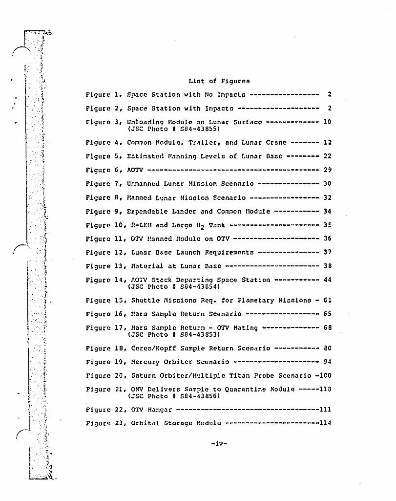
Lint of Figures
Figure 1, Sp.lce Station with Ho Irnp:1cta ----------------- 2
Figure 2, SpacQ Station with Impacta -------------------- 2
Figure 3, Unlo~ding Module on Lunar Surface ------------- 10 (JSC Photo I 504-43855)
Figure 4, Corn::lon Hodule, Trailer, and Lunar Crane ------- 12
Figure 5, Esti~ated Hanning Lavelo of Lunar Dane -------- 22
Figure 6, ~OTV ------------------------------------------ 29
Figure 7, U~~~nned Lunar Minoion Scenario --------------- 30
Figure 8, Manned Lun~r Hinoion Scenario ----------------- 32
Figure 9, Exp:mdable Lander and Common Hodule ----------- 34
Figure 10, R-LEM and Large "2 Tank ---------------------- 3~
Figure 11, ON Hanned Module on OTV --------------------- 36
Figure 12, Lunar Dase Launch Requirements --------------- 37
Figure 13, Material at Lunar Base ----------------------- 33
Figure 14, AO~V Stack Departing Space Station ----------- 44 (JSC Photo 0 S04-43054)
Figure IS, Shuttle "iosiona Req. for Planetary Hisoiona - 61
Figure 16, Mnrs Sa~ple Return Scenario ------------------ 6S
Figure 17, Mars Sample Return - OTV Hating -------------- 68 (JSC Photo I S84-43853)
Figure 18, Ceres/Kopff Sample Return Scenario ----------- 80
Figure 19, Mercury Orbiter Scenario --------------------- 94
Figure 20, Saturn Orbiter/Multiple Titan Probe Scenario -100
Figure 21, OMY Delivers Sample to Quarantine Module -----118 (JSC Photo 0 S84-43856)
Figure 22, OTV Hangar -----------------------------------111 Figure 23, Orbital Storage Hodule -----------------------114
-iv-

.... -. [ .. ~ . .:
rIl··········,-····.···· ~l r
1 i .-
:J ! '-1
.' .J ·1 .:~
;.]
.. ~ .... '1
:.", ." ~ :." . ' .... ;.
, I L
I .• i .. ~.:" • i
... J '.'. . ... j - ~.
'-." '"-'j
Figure 24~ orbiting 8urifant!ne ~aeiiitr ~=~=~~~~=~~=~~=~~12a Figure 25~ IntJriof of tatiokStory H8dui~ ::~:::::~:::;~:~i2i Fl~ur~ ~6; tIfe Sci~~~&~ Lab Hoa~le ~----~::~~-~::::~::~-i23
OR!GtNAL PAGE rs OF PC<:Al QUAlfN.
II r \ _.i . -!
r
lj l)
, • ~ .. >
.-','
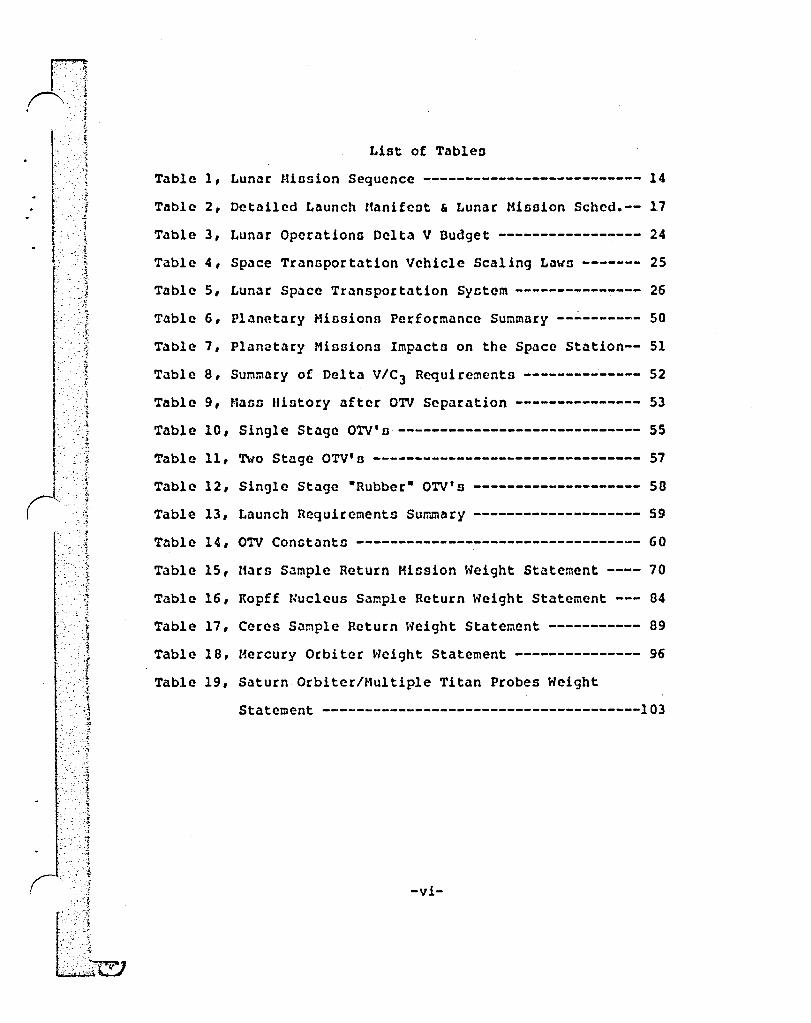
List of TableD
Table 1, Lunar IHnsion Sequence -------------------------- 14
Table 2, Detailed Launch Manifeot & Lunar Mission Sched.-- 17
Table 3, Lunar Operations Delta V Budget ----------------- 24
Table 4, Space Transportation Vehicle Scaling Lawo ------- 25
Table 5, Lunar Space Transportation Syctem --------------- 26
Table 6, Planetary HissionD Performance Summary ---------- 50
Table 7, Plan~tary Missions ImpactD on the Space Station-- 51
Table 8, Summary of Delta V/C 3 Requirements -------------- 52
Table 9, MallO lliDtory after OTV Separation --------------- 53
Table 10, Single Stage OTV's ----------------------------- 55
Table 11, Two Stage OTV's -------------------------------- 57
Table 12, Single Stage -Rubber- OTV's -------------------- 58
, .~ Table 13, Launch Requirements Summary -------------------- 59 .: -~~
. . ... ,~" ,
Table 14, OTV Conotants ---------------------------------- 60
Table 15, Mars Sample Return Mission Weight Statement ---- 70
Table 16, Kopff Nucleus Sample Return Weight Statement --- 84
Table 17, Ceres Sample Return Neight Statement ----------- 89
Table 18, Hercury Orbiter Height Statement --------------- 96
Table 19, Saturn Orbiter/Multiple Titan Probes Weight
Statement --------------------------------------103
-vi-

;:-r ... -.. : .-:_,.3.:' ." . . . ' :i
- . - . :.~l···. '~ .'. ~
. -, ~,.
_ 1 .'. _r
-J ;l
~.
Foreword
Thi~ study was conducted between June and November of 1984 by Eagle Engineering for the Planetary Exploration Division of the Johnson Space Center. The purpose of the ~tudy was to assist Space Station designers in planning for future needs, and to ~ee what a conservative design Space Station/O'lV inf rastructure can do for a lunar base build-up and for advanced pl ane ta ry r:li os iono. Three other inter 1m reports \/ere produced in this study. This report includes all the material from all three. A slide presentation nnd technical paper were also produced for the Symposium on Lunar Bases and Space Activities of the 21st Century, held in Washington D.C. in October, 1904.
Gus R. Dabb served as the study leader for this effort. Significant contributions were also made by the following Eagle team members. Paul G. Phillips and William R. Stump made up the engineering staff for this project. R. Patrick Rawlingn and Mark W. Dowman executed the airbrush art and other graphics. Eric franklin provided graphics support. Willard Taub and Richard B. Ferguson designed the propellant storage modules. Hubert P. Davis and W. B. Evans provided technical and editorial supervision.
-vii-
~ ..: I '.' .
1.0 Executive Summary
The impacto upon the growth Space Station of ceveral advanced planetary mission~ and a populated lunar baGe are examined. Planetary missions examined include oample returns from Hars, the Comet Kopff and the main belt asteroid Ceres, a Mercury Orbiter, and a Saturn Orbiter with multiple Titan Probes. A manned lunar bane build-up Gcenario io defincd, encompassing preliminary lunar surveyo, ten years of construction, and eoti!blishment of a permanent 10 person facility with the capability to produce oxygen propellant.
The spacecraft maos departing from the Space Station, missiQn Delta V requirements, and scheduled departure date for each payload outbound from Low Earth Orbit (LEO) are determined for both the planetary missions and for the lunar bas~ build-up. Large aerobra~ed Orbital Tranofer Vehicles (OTV'o) arc used, similar in concept to those now being designed for geosynchronous orbit missions. Two 42 metric ton propellant capacity OTV's are required for each of the 68 lunar sorties ()f the base build-up scenario. The two most difficult planetary misoions (Kopff and Ceren) also require two of these OTV'n.
An expendable lunar landcr and ascent stage and a reusable lunar lander which will usc lunar produced oxygen arc sized to deliver 18 rretric tons to the lunar surface.
For the lunar base, the Space Station must hangar ~t least two non-preosurized OTV'o, store 100 metric tons of cryogcns, and oupport an average of 14 OTV launch, re~urn, and refurbishment cycles per year. Planetary sample return missions require a dedicated Quarantine Module.
An average of 630 metric tons per year must be launched from the Kennedy Space Center (KSC) to the Space Station for lunar base support during the ten years of base constructiQn. Approximately 70\l of this cargo from Earth is OTV hydrogen/o~ygen propellant. An Unmanned Launch Vehicle (ULV) cap~blc of lifting 100 metric tons net useful payload is considered necessary to deliver this propellant. An average launch rate of one shuttle and one ULV every ten weeks to the Growth Space Station will provide the required 630 metric tons per year.
Figures 2 and 1 show the Space Station with and without impacts from the lunar and planetary missions. Figure 1 shows the Space Station without OTV hangars or propellant storagp. and transfer facilities. The entire OTV infrastructure should not necessarily be considered dedicated to the lUnar ~nd planetary missions. It is more likely the OTV infrastructure will be put in place earller to support revenue-generating missions to geosynchronous orbit.
I

-.' l,
-;; c', ~-J
.. :; , ",~
-'{ :.
- ';;
"
",
ce Station Sp~ h Impacts Wit
--,-:
2
.' •• <
"--,' :";- -.:~ , -l
'~f"-' > :\ ",,,,';(:'1:' ,-~>,
-," • > .~:...). "- ~ •• -
--. ,.. ~-
FigurA 1
t" n Space Sta 10
,- with No Impacts -",,'t - I
ORIGtNAl PAO:;Z fS OF POOR QUAlllY
~~1
'6f?'1 • •
~~"5.~:.' .!
- ... ;; .. J.
,~ .;
"
.~
". ! , J , ?
." .... .. ' . .:;.:-
,',' ,f .. , '" ... . ,
.: "l.A '\ 1;., . ~ .::' ; ;.-.
. :-y .~ ,
2.0 Introduction
NASA and contractor a are now working on the conceptual design of the Low Earth Orbit (LEO) Space S~ation. The designers must include in their thinking, for the early (Initial Operational Capability, or IOC) Space Station, the requirements of th~ turn of the century -Growth- Space Station. This study, performed by Eagle Engineering, In~. for the Johnson Space Center (JSC) Planetary Exploration Division, examincn the impactn of advanced lunar and planetary minsions upon the Growth Space Station.
HasG ~stimates were conGtructed for a science-emphasis lunar base using lunar produced oxygen, a transportation system sized to land its clements on the lunar surface. ~ ten year flight schedul~ was developed, including weights, propellants, crew size, etc. and then the impacts upon the Space Station ~'erc estimated.
In a similar manner, five advanced planetary missions were examined - three sample returns and two orbiter/probe missions. tieight statements and trajectories for each of these were tabulated. The propellanc loads, configurations, and mission plans of single and two stage stacks of conceptually designed standard OTV's (Orbital Transfer Vehicles) were also developed at this time. From these requirements the impacts on the Space Station were then estimated.
3

<"
L
_iZ
; .'
3.0 Groundrul~a G.Ao6umptiono
The follo~ing groundrulco and ansucptions were used in thio study:
1.
2.
3.
4.
s. 6.
7.
8.
9.
10.
11.
12.
13.
The Space Station c~n otoro and tranafer L02 and Lij2 to the Orbital Transfer Vehicle (OTV) 1n orbit. See section 6.2 for il dincuesion of the ntate of the art in thin c.echnology.
Aerobrakiny will be a mature technology and io incorporated in the OTV design.
The OTV will usc L02/UJ2 propellant.
OTV lap • 460 aec with 1% atGrt/stop lOGses yielding an effective OTV lsp D 455 nec. fo: cry~genics (from Ref. 2).
lsp = 340 sec. effective for ntornblc f~el0.
All stageo, Lunar Lnndern, etc., will be L02/tH2 u.lcss stLQn~ contr~-indicated.
Jlitc~tiOD - E::pendal;)le aocent stago wll1 uce otorables.
Boil-off rate for cryogenic stages io 55 kg/day o~ LH2 p~r stage. (R~f. 2)
Cargo unitn for the lunar bane weigh a mDxi~um of 17.5 metric tonne Thin is the estimated voight for a Space Station Common Hodule.
OTV elements can be lIotacJ:ed,1'I i. e. used as two identical stages, one staging before the other ignitea.
Lunar surface otorage, tran~fer (into Landers), and rerefrigeration of cryogenics, both L02 and LH2' is assumed aft~r 02 production commences.
The lander can be ma!ntained at the lunar base.
For the purpone of this study: Lunar O2 will beconle availab'-e after delivery of the production plant to lunar surfac.e. This O2 will be used in the reusable Lunar Lander, but delivery of Lunar 02 to Earth orbit will not be examined in this study.
The OTV will be sized to perform any of three reference missions:
A. Deliver 9 metric tons to geosynchronous orbit, returning empty using a single atage.
4
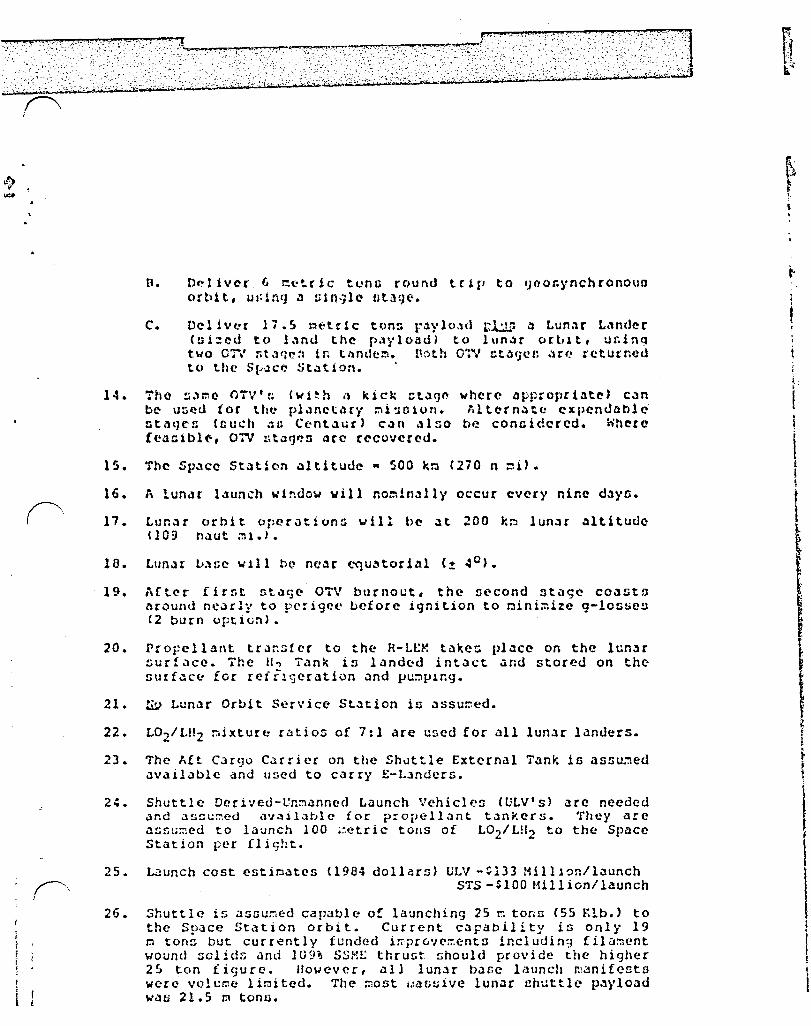
~ -fl. D~11v~r 6 c~trjc tuno round trip to ~oo&ynchronoun
orbit, u~lnq ~ ~ln~l~ nt1ge.
C. Del ivt-r 17.S !!It:-tdc ton:. f.lylo,ld r..J...1...": .:l Lunne L.,ndcr ( !i i :!: edt () 1 ~ n d the p ., 1" loa d ) t 0 1 \I n ~ r (1 r tJ " t, u r. i n q two OTV r.t;vlc-:l in tl'lndc!:l. n:':lth O'l'V !:tlH)CI! .Hf! returned to the S~JC~ St~tion. .
14. Tho ~."r.lC- (lTV' t; (wi~h .1 kick :::t.lCJO where lIpp::opril1t~) Coln be- u:)~d tor tht: pl.lnetl,ry !:li'1Clon. '.lt~rnolt(J expendable Dt.1qC!l (nuch ~i.l Cent.1ur) coln <11:'0 b~ concidered. ohera !c~~lbl~, 07V ut~~~n ~rc rccovcr~d.
IS. The Sp.1ce St~tiDn .lltltudc " 500 k~ (270 n =1).
16. A lunar l.1unch wlndo~ viII no~in~11y occur evcry nine d3YO.
17. Lun:lr orbit operation:.; will be .It 200 k~ lun.lr .lltituue (109 fl.}ut ~1.'.
19. ,\£ter firr.t Gt.'HjC OTV burnout, the !It:'cond !It'lgc COolstfl around nc~rly to perigee before ignition to nini~ize q-loGUCS (2 burn option).
20. Propellant tr~~s[cc to the R-LE~ takec pl~ce on the IcnJr !;Ur!.lce. The II., Tank is lilndcd intact .:lOU stored on the Gurf~cc ior rcfrlgeration ~nd V~~p"r.g.
21. !i.:) Lunar Orbit Ser .... icc St.ltion is .:lssu~ed.
22. L02 /I.t!2 ::oixturc rlitios of 7:1 are ur.ed for all lunar landers.
23. The I,it Cargo C.urier on the Sh~ttle External Tank is a55u~ed available dnd used to carry E-L.lnders.
24. Shuttle Dcrived-Vn~anned Launch Vehicles (ULV's) olce needed <lno .:1sc\;~ed <l'J311.:ltJlc for p:opellant t.lnkers. They arc ')!;fa;:r!cd to launch 100 ~=.etric tous of L02/L!l2 to the Space Station per flight.
25. Wunch cost estio<ltes (1984 dollars) ULV -~133 Milll~n/launch STS -SlOO fHllion/launch
26. Shuttle is :tsDu!7icd capable of launching 25 :':l tons (55 Klb.) to the Space Station orbit. Current capability is only 19 r.J ton~ but currently funded irrprovc=ents including filament wound solidG and 109' SSME thruGt Ghould pro .... ide the higher 25 ton i igur-e. However, elll lunar base launch r:;~nife!ltn wcre volt;t:w lir:lited. The ::lost i.!ilGuive lunar 1!huttle payload waf; 21.5 p tonu.
~ r ~l
\ .
I
\ I • . t t I,

)l ...... ,.i .' .. -........• _. ," , .
.. .. . -:~
". ":.-, ~ ','-:'
; -0 • f,
4.1 Introduction
Thin ncetion ot tho Dvcr~ll otudy Invcutig~tco the icp~ct on tho Sp~cc Gt~tjon of nupportlnq 4 ~~nned return to the lunAr nurt~cu. The env~91onftd return ~nt411o tho conntruction and opor4tion ot a largo, PCf~~r.cnt b~att cleulqnod to c=ph401:o lun~r uc1cnco ~nd lun~r rCfiource utl1iz~t1on.
ElIeIler ,1SC in-hauDo ntudl<!{l !He!. 1) on the "lun~r 1nlt1:ativc· h~vn Dhown th~t a tc~nnpoct~tlon nyntca cacpoced of ~ Sp~ce St~tlon co~bln~d with ACfobr4klnq Orblt~l Tran~!er Vchiclca CAOTV'nJ, deotgnod for round trip delivery to 9co~y~chronoun orbit, Citn fl',HHly prOVide tcanlJportl1tlon !ro~ 10'l0I !:.:2tth orhit to lunar orbit itnd bJC~. What h3~ not br~n prevloucly ~x~=lned 10 thQ i~p~ct upon the current up~c~ at~tion conccptG o! tho routine, contlnuln9, large ocalQ tc~n&port4tlon noedo of ~ ocrlouu lun~r pro9f.ln.
Thin utudy !G to ~neenn thtl rcpre:wntlltivo tr(.iflnportation r('..,u1re~cnttl of ouch ., progr~~. To en:lble thl0, (1 roprc:\!f1t.:\tlvo lun~r b~Ge °cod~l· and build-up ochedulQ vore defined.
'rhc ei::Gion ~odcl prC6cnt(NJ 10 b~~cd upvn thil lun.1r bam: buildup d~acrlhed 1n Ro!arence 1, vhich wan produced In-houae "t JSC. Thin ".'Hi .:H!q~('ntetl \11th oper~tionG t:ccn~r 100 fro~ t~r. (jecne! Roberto of JSC'~ $y5tc~tl £ngincorln9 Divlo1on. The rcnult va~ u~cd .1~ the tr~nnport~tion obJcctive.
A net of necen511ry r;p,ll.C! tr.lnnpocto!ltion elc:!~ntu ~crc defined l1nd nl:ed, includin9 OTV ele~ento, lander!), cnnned ::lodulca, etc.
Vehicle inert weight Bealing foroulae for this exereize ~rc taken tro~ Reference 2, (Scc Table 4). Lunar L4ndcra hnve an inert weight increpcnt cqu~l to 2\ of the n~xi~uo 14od~d ca~~ for landinq gO.1r.
The lunar delta V budget in b<lsed upon Apollo 11 data (Reference 3) olltered to reflect the different opcr~tional altitudes. Hidcourse budgetB vece enlolrged to yield plane change c~p3bility of 25 0 4t the Qravitational field interface between the Earth and the Moon. The Apollo 11 ~icslon usee 11 f~st, 2 1/2 day trann 1 t, f ree- rcturn traj eetory. Later Apollo Dicsions used slover (up to .: doli') non-iree-return trajectories. Thene yielded nignificant delta V reductions, particularly in the Lunar Cibit Insertion (LOll and Trans-Earth Injection (TEI> maneuvers. The c.,p~bility for the faster flight tirne has been built into the delta V budget for this st~dy so that flight ti~e can be varied as necessary to allow launch windows that are several days long at nine day intervals.
The ninc day ~iGsion opportunity interval is created by the requir~~ent to depart frc~ the Space Station orbit. Reasonable transfer opportunities occur only when the r-leon is in, or ncar, the plane of the Space Station orbit. ~his occurs every 9 days as the Hoon revolve~ around the Earth and the Space Station orbit prece~ses in the oppoGite direction.
6
18 f
I .
; -
I'
r-" I
4.2 l'Jnl1f Dnne Dcccrlption
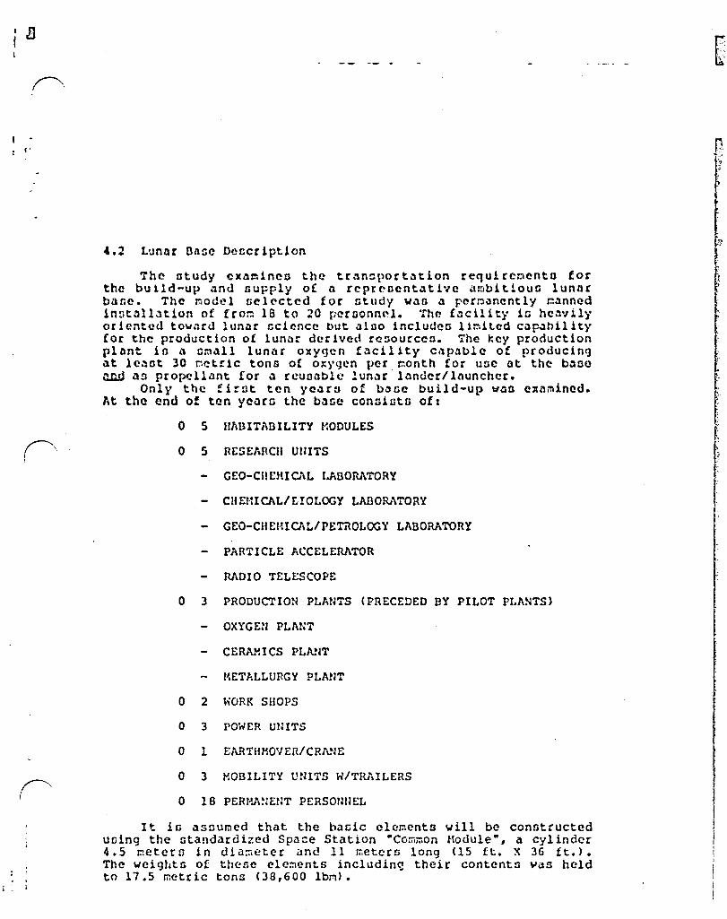
The atudy cx~~lnc(l the tr~ncportation requircoento for the bUlld-up ~nd (lupply or n reprcncnt~tlvc ~mbitlouG lunnr bl1tc. The ::lodel nelcctcd for ntudy WolO l1 pcrp.Jnently r.:.'1nncd InDtnll.ltion of !rop 18 to 20 FNGOnnol. The (~cilitl ie hc~vlll' oriented tow~rd lun~r ~cienee but ~lno ineludea 11~itcd Cap<1hility {or the production ot lunar derived rc~ourccn. The key production pltnt io l1 eml1l1 lunnr oxygen f~cl1ity c~p~blc of producing l1t lCl1Gt 30 petrie tons ot o~ygen per month for uuc at the b.'1oe rullJ l1!l propelll1nt ror .l rcuDl'lblc !unlJr lllndcr/inuncher.
Only the !lrot ten yel1rn of b~ne build-up Vlln e~amincd. At the end of ten ycnrn the bl1se conniot6 oft
o S I~UITADILITY MODULES
GEO-CIIEHIC'\L I.ADORATORY
CHEHICAL/r.IOLOGY LABORATORY
GEO-CIIEMICAt./PE'mOLOGY LAeORATORY
PARTICLE ACCELERATOR
RADIO TELESCOPE
o 3 PRODUCTION PLANTS (PRECEDED BY PILOT PLANTS)
OXYGEN PLANT
CERAHICS PLN~T
r~ETALLURGY PLNlT
a 2 WORK SHOPS
o 3 POWER UNITS
a I EARTHMOVER/CRANE
a 3 MOBILITY maTS W/TRAILERS
o 18 PERHA:jEr~T PERsmmEL
It is assu~ed that the bacic clements will be constructed u01n9 the standardized Spa=e Station "Cor.i~on Hodule B
, a cylinder 4.5 r.letern in dia::1eter and 11 meters long (15 ft. X 36 ft.). The weights of these ele~ents includin~ their contents ~as held to 17.5 metric tons (38,600 Ibm).
. " .6
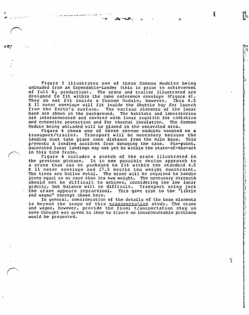
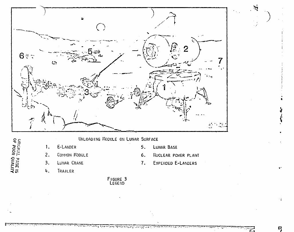
Figure 3 illuntraten on~ of theGe Common Modulen being unloaded froll! an E:cpcndablc-Landcr (thin in prior to .lchic .... c::'\ent of full 02 production). The crane and trailer illuntr~ted arc deniqned to f it within the name rcfcrenc~ envelope (Fiqurc 4). They do not fit !nnide 11 Common HJdule, hovever. Thin 4.5 X 11 neter onv~lopc will fit inside the Shuttle bay for launch from the Earth'n our!ace. The varioun clements of the lun~r b~Ge arc nhow" in the background. The habit~t!l and laboratoricn arc interconnected .lnd covered with lunar regolith for radiation ;lnd J:)<!teorite protection <lnd for th~rr::cll inoulation. The Co~on Module being unlL.ldod will be placed in tho excavated area.
Figure 4 shows one of these com~on moduleB mounted on a transport/tr;liler. Transport will be nccenDary becaune the l;lnding mUGt take placc nome diot.lncc from the main b~ne. This p:cventn a l~nding accident from d~~aging the banc. Pin-point, ilu~o:nl;tcd Iuniu lilndingn I:!ay not yet be within the llt\itc-of-the-,ut in thin tine fra~e.
Figure 4 includcs il nketch of the crane illuntratcd in thc previous picture. It in onc possible denign approach to a cr~ne that can be packaged to fit within the st~ndard ~.S X 11 Dcter envelope and 11.5 metric ton weight constraint. The tiren are hollow metal. The crune will be required to hilndle itc:ns equal to or pore than its oun weight. The necessary strength should not be difficult to achieve, considering the low lunar gJ:.lvitj', but balance will be difficult. Transport using just the crane appears impractical. This gave rise to the Dlittlc red wagon- concept shown here.
In general, consideration of the details of the base clements is bt"yond the ocope of this trjl05portil.~ study. The crane and wagon, however, provide the final t:ansportation step so some thought was given to thel:! to i~aure no insurmountable problems would be presented.
" .,
, .

r·'·
! . I
I ..
• It ..
4.3 Lun~r n~oc Ouild-up Scheme
The lunar b~GC ~inoion oequcnce baginn with prcli~inary orbit~l gco-che~icnl mapping via n ontcllite placed in a low lunnr polar orbit, {ollo\JcJ by S )'CHlrn of rCf:lotc -lunar roverourfncc invcntigationn and oite Gelection. Starting in the yc~r 2005, the actual ~uild-up of the lunar bane begina. The bane in fully operational by the year 2r,1~.
'l'hin build-up requi reli del ivery of the following:
Major Lunar Bane Elc~entsl (17.5 metric ton cargo unitn)
o Enrthoover/Crane - 1 o Power Unit - 3 o Ifabitllt - 5 o Lunar L02 Pilot Plant - 1 o Lunar LO~ Production Plant - 2 o Unpresnurizcd Mobility Unit & ReillY Station - 1 o Prensurized MObillty Unit - 2 o Geo-Chc~ical Lab - I o Geo-Chemical - Petrology L<lb/Oboervation Equipment -1 o Work Shop - 2 o Ceramics Pilot Plant - I o Metallurgy Pilot Plant -1 o Particle ~ccelerator - I o Chemical/Biology Lab - 1 o Cera~icG Plant - Operational - 1 o Metallurgy Plant - Operational - 1
Plus Light Units: (9 metric ton cargo units delivered during crew rotation flights)
o Ground Relay Station - 1 o Radio Telescope - 1 o Power Converter - 1
Starting with the year 2005, Gome 3 to 5 major elements per year ar~ delivered to the lunar surface; manned sorties occur every 3 to 4 months. Each del ivery or manned mission requires a two-stage OTV sortie plus an expendable lander and, for the manned mission, an expendable launcher. The manned missions also require a reusable manned module to carry men on the OTV, an OTV Manned Module (OHM), and a manned module to carry men on the landers, the Lunar Lander Manned Module (LLHH). This last element may be expendable initially, but will be reused and stored at the lunar base once lunar produced oxygen and the reusable lunar lander become operaticnal.
During 2005, the fir~t year of bane build-up, a power unit, crane, trailer, and one laboratory ar~ deliverud On unmanned flights. Two manned sorties of approximately one lUnar daylight period each, 14 days, arc then flown to prepare the base and
r
.. I
" i 1
1 I i i t ] ~
i ,.
) ;
,.
(')
., . ) /~. // ~ .
;'
I) ;;
.-.-....... ,-, ~ .. --- .. -.... -
\" ., .. i"-/ -.:.--.....'
6
'-.. ' J . '\ . ~"
:.: _~. _."~ ;~.c.,:~' "," 5 _.~ I,' '~ .• ' , ' ~, y" . .•• ,'C::; .,,= - ',r.-'i' " '} -' -:1-'''- t.') r-:;;;~~ .u .' / -" '\:~:ij: "r.: ' . .' 2 , • • . ,. • -'J . • __ ' 0.: .
I ~ ~ 7'';;' . ./ . ' ~ .,. __ • '. ~1_JJ" .. - 7 .... : \".'~'" /.- .- ."..... .. ~) ~."-'1' 1?t: I.' --- ~--- .... , .....,." - /I • - - -~ --....- .•• .. '-J' Z -"'" ",.,. • .' -?" ..... ~. ~ ,-,
" r ~ ;r-• .;:;:C:-1 • .... ,-;,.! - .n"';. '- ~\ II ... co:;;;;..· . /../ ...... -".--"
. 1 ' . ~~ '. ',' -. '''''' ,r , . · - -" "'~"""'. .. _, " _ ., " . '3' - ... ,. . - ( , I' . '-~ , ." _, " • ...... .. .. ., ../" '.' 1 \ -r- .-'-. f', . -
• ! ., ._" .. ' '. .,,_ . ' ", 1 \. I
• ,. '. ~. ;" ... ,. <;.-;-" """.' .' , I . , _. ~, > .' "'''''~ I ~. , '- ., ~. -, . --.. -~- " . ... ,:--LJ-. _.... fl.-' ~-- ..... ~r,:..9 :,,' ..... ,,~\ . . .-.~ c: J ,_ • ~, ". , /' J.., ..... , " · ~ ~ ,'....,., / .... /, .....
4 I . ~.~:.,~ - • ''j,'./ ~''';J.!' ,I . \ 11'.. / ."", ~~/" I ,: ;,.\i ~.- . "
I, .~~~
...... _.- .... -........ -,/'0
l' .~ i~\ ' I · ~ '::'~":Il • ;;" J . \ ' ,,'')If
• #I t. .. ••
4' •
Oc "11:.1
8~ ~ i:;
10-0 c: J'" ~ (.) r-M
~Ui
"
1.
2.
3.
4.
--UNLOAD I NG r'~ODUL E OU LUNAR SURF ACE
E-LANDER
CO:·U·\ON MODULE
LUflAR CRANE
TRAILER
FIGURE 3 LEGEIlD
5. 6.
7.
LUUAR BASE
NUCLEAR Po.'IER PLAtH
EXPENDED E-LANOERS
...... ~ ... ,
~ . . .)
f;)~0"~' ':' ~": .... .; ," ;. " :-" .,' d ,"'n'·"'-'~R •.. , ,,,,h .. .',( .J.""~~"~t:c'.;., ,,,"" .... J ..... ;i:"-;;,i";'.,,,,,,.of "':>,,, •• ' ~~";";""Y , .• ,;,.." 1-:-'->""" .. ",~"""~\,,,,,,.,,,T.,, ... ,,-,r, ·l'.":",~\"i'T, ., .+",., '\." .... ~ ... , j," "" .,..'.' s,. t" t'N~, '"."';,,:,.;, ~;.::;I a_'!I
,
~
~ ..
...
. i
~

.... ..
..... , .;,
•
Figure 3
"
. .. . .
..
.'.
j .. j
~! .j
J ! t

• .r,.. ,'.
, ~
I -0-----'"
~ \ ~----..:>j
(
;
!
< '. - ·t
\. ~
" i '" .j~'
" ... f.
c
F'fnllrA .d.
.-.~ ',-~.. .' ; .... ~ ... ~(~
I , .... :.~.< ;1': /.:.~ ;.,.
"
" . \
" '-.: ."'" ';' a'. '.\ . J.
:~ .~ 'f
0
Q) t: ct1 t.. O I..-«1 e ::J
...J
~ '.
0) -:J "0 0 :2 c: 0 E E 0 ()
.r::. <-' 0-
~ t-
~ .- i CO
, l..-r-
: .
cU
~ .
... ; ~. ~
.1· ';- t
~J 11
'O-f
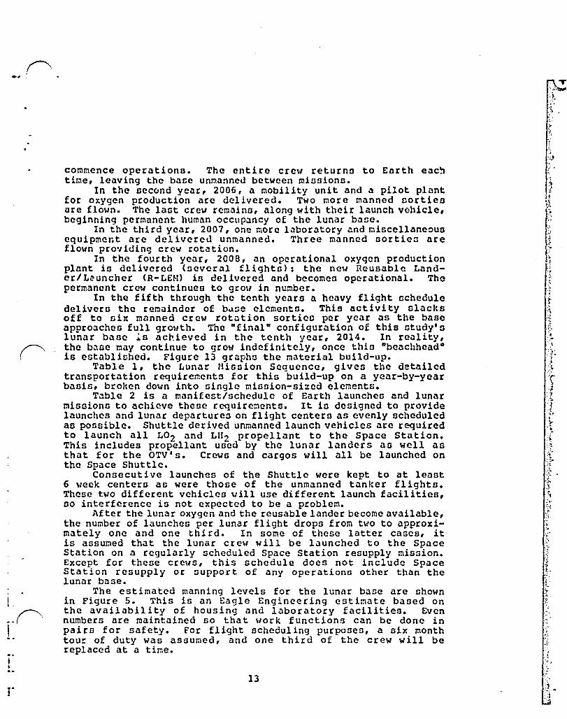
commence operations. The entire crew returns to Earth eac~ time, leaving the base unmanned between miosionn.
In the second year, 2006, a mObility unit and a pilot plant for oxygen production arc delivered. Two more manned sortieo are flown. The last crew rcmaino, along with their launch vohicle, beginning permanent human occup~ncy of the lunar baoe.
In the third year, 2007, one more laboratory and mi6cellane~us equipment arc delivereu unmanned. Three manned oortieD are flo~n providing crew rot~tion.
In the fourth year, 200B, an operational oxygen production plant io delivered (ncveral flights): the new Reusable Landcr/Leuncher (R-L£H) is delivered and becomcll operational. The permanent crew continues to grow in number.
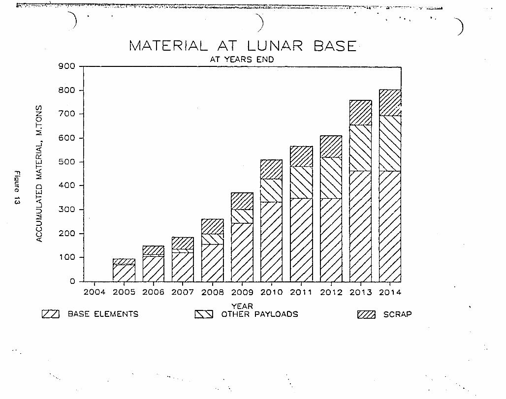
In the fifth through the tenth years a heavy flight schedule delivers the remainder of b~se clements. This activity slacks off to six manned crew rotation sortieD per year as the base approachco full growth. The -final- configuration of this study'o lunar baoe ~B achieved in the tenth year, 2014. In reality, the base may continue to grow indefinitely, once this Dbeachhead D
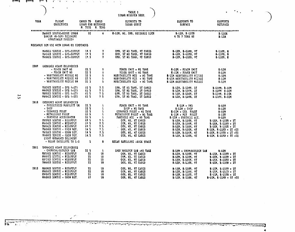
is establiohed. Figure 13 graphs the material build-up. Table 1, the Lunar Hission Sequence, given the detailed
transportation requirements for this build-up on a year-by-year basis, broken down into oingle mission-sized clements.
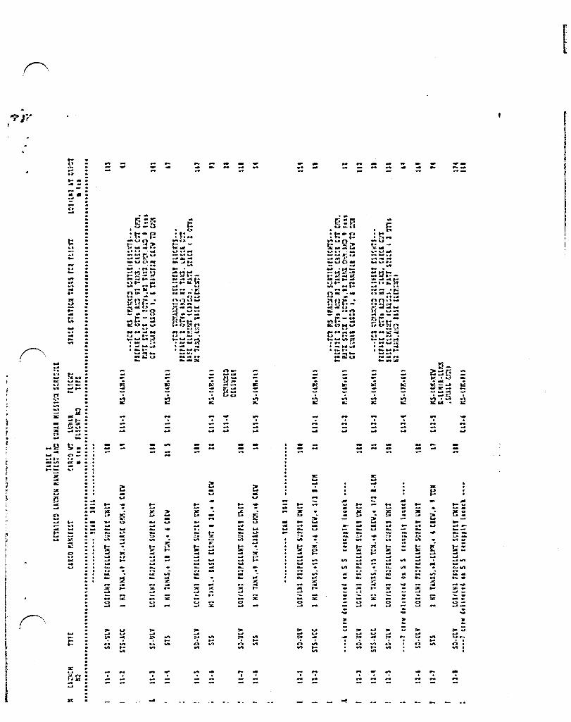
Table 2 is a manifest/ochedule of Earth launchen and lunar misaiono to achieve thene rcquire~ents. It in denigncd to provide launches and lunar departures on flight centera as evenly scheduled as possible. Shuttle derived unmanned launch vehicles are required to launch all L02 and LU2 propellant to the Space Station. This includes propellant used by the lunar landers aD well aa that for the OTV's. Crewa and cargos will all be launched on the Space Shuttle.
Consecutive launches of the Shuttle were kept to at least 6 week centera as were those of the unmanned tanker flighta. These two different vehicles uill use different launch facilities, so interference is not expected to be a problem.
After the lunar oxygen and the reusable lander become available, the number of launches per lunar flight drops from two to approximately one and one thi rd. In some of these latter cases, it is assUI:led that the lunar creu will be launched to the Space Station on a regularly scheduled Space Station resupply mission. Except for these crews, this schedule does not include Space Station resupply or support of any operations other than the lunar base.
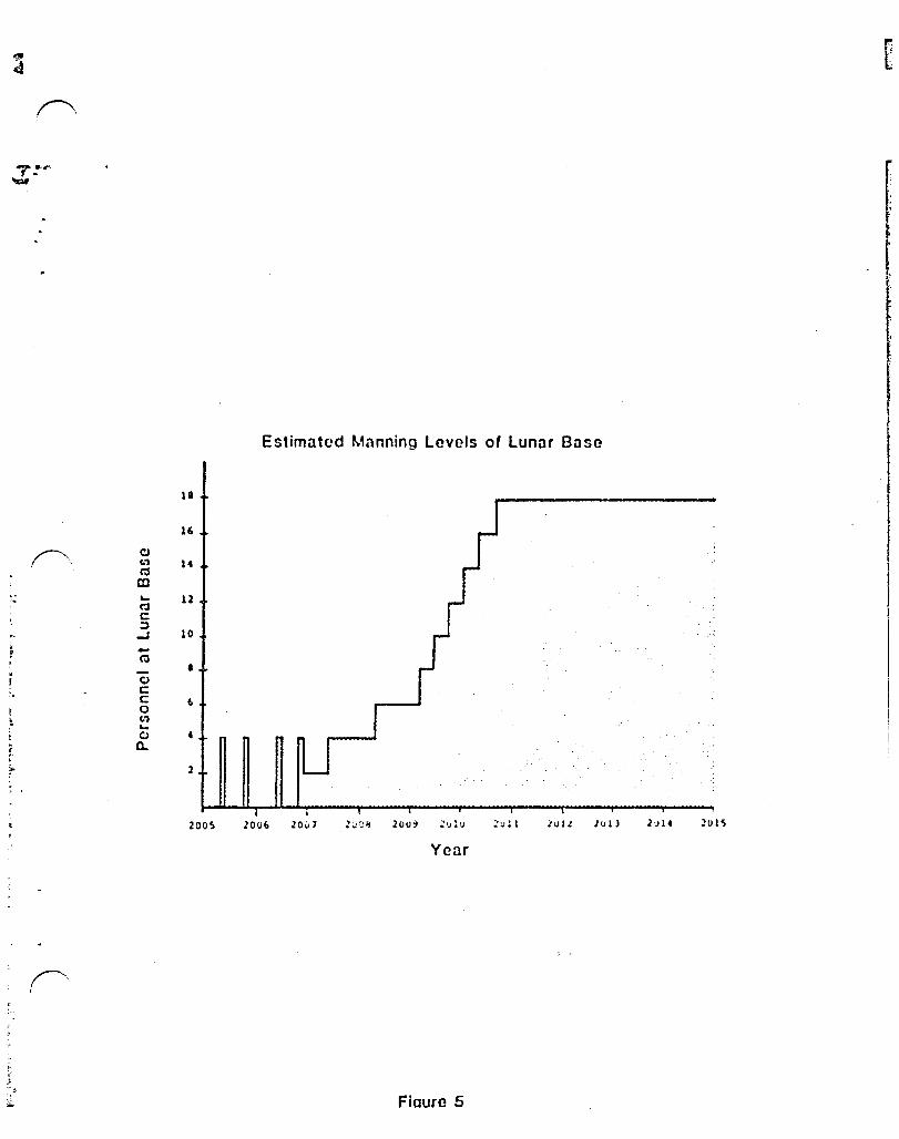
The estimated manning levels for the lunar base are ahown in Figure 5. This is an Eagle Engineering estimate based on the availability of housing and laboratory facilities. Even numbers are maintained so that work functions can be done in pairB for safety. For flight acheduling purposes, a six month tour of duty was assumed, and one third of the crew will be replaced at a time.
13
.. > ~,
:.) .< •
'.
:.;..
T

-j ) ') TUlt I
LVflU HISSIC1t stQ~tKCl
lUI rLICKT CUCO TO cuco tl t,it:1i5 TO U omrrs 'ro nnmrrs OBJECTIVES L~,}UIl o!a ltTUl'JItD m(lll emT S1IlUCt ImutD
n, TOllS n. TiliU •••• ,la.I~.a.~.I.I •• 2.1 •••••••••• II •••• II •••••• I •••••••••••••••• 1' •• " •••••••••••••••••••••••••••••••••••••••••••••••••••••••••••••••••••••••••••
ItIl CILIVU !;to· U CtO·n1Pfl! Sl~lllTt ~fPtl SlTtltlTt
un IltLIVtl ~~\}I.m\tD 4 • SURflCE IO.tl/tIPlCltl·l/tl 1rel IOYU PLUS SlUll Llf:lltl Tliia~CK SUi£lCt tlPLeital le:.l n: fUll HU PoOHa I Pta 11.
t:on: tum.'Jl TlPt IUSSICit
STllT L~l 51St aUILD~p
1m ~~~KXtO RE1Yt OELIVtlltS • tARrH~QVtllt!lHt lS , E·lll::n • tl1l1E tUllE - rO:iCi L'llIT II 3S 0 t·UJa:tI t rUII J\o'l. ~"lIIT 11 - lU61TlT II 15 0 [·UIOn • F".i!1l lUX. V.1EIT1T 11 • eta Ciltll lU lS 0 t·LlXJtl • CtO tKIM til CtO.Clltit til
I'!lk'lltD SCiTlt·USt SET·UP n on·lUtoC:tD rlmtt (Or:;tltt\l'iUl LLli:1 t t·1SCOIT Lt~ t L~I Sl~lt .... lJ.;;:m.:c r • .H:.1!:l r.:JD, (Ll!:1) or:.. • t·w:~n • t·lseEm • 1 lOll rL
KUiXtO SOiTIE·llSt OPS 11 C~. LLI'JI. [·UJ:llU. [·lSWIT •• IT LOO • I·HcM tLJOt • L~'UI soon
1m 1m1UC([O HU.t DtllVtllltS - U~f~tSS~llltO ~JilllTT
UXIT • ~tlAt STATION 15 • [·LllQtl • cmo l.':1lT fiOllLtn tnlT - nOI mOT 'lOO n • t·LUUln t u.neo t':IlT LtOI PILOT PlUff
IUtilitO SORTI t 11 l om, lllC!. E·UKDtl. t·l~wrr •• IT 111-:1 • [.lSWo.,. tOO • l1.1U1 !innt I'J..~UO SeliTi E n , onn. 1Lf.J. t·LlY.DtR.t·AScEKT,.IT lml • E·lswrr LLI"'JI • l!;'lUl S11t7 II
tel? Plltt L·l ltllT SlTtlLITt '.5 ltLl! SlTELLltl Ire L-l rOSITIOX)
~1:lU101IO HmT llELIvnttS - etOI tNt!1 Ptn.OlCCY UB n • t·lllmERtC1RCO tlt~tHT CtO·CRt~ FtiiQlCCt
um SG!\£ :15, [aPT. tlD fLwl CJSt'Yl!Clt
- 1I1);;itO somt II/1UMRl n , OnM. Ll!\.'l. l·tlk"DtlI.t·l5e[~rr •• 1T tLl'J1 • t·iSetr.T • n PlL 111!."l - ~lKAtD selTlt IIINtTVOil 11 , 0;:1. LLm, t·l~ta,t·HCtl:r •• 1T lllil1 • t·1SttlriT • 1Y ill - IUHatO SOlTIE IIINtii~ll n , C~, lL~4, t-l~tl,t·1SttH,.,.lT
1m \i'lOlJJOlt~ HUvt OUIVERT - LUNll CROIT SPlct S71TI lS • lOSS • LLOI PRoc~eTIOX UWIT II n • t·LUeltl t LOI ftCOCCTIC~ rL~~ LLOI rROu~CTlon PllXT - ltC' PlnC~CTIOK UNIT 11 n • E·L~tl • LOI 'ROQUeTIC~ 'LlSiT • L01DI~; £lCILITI
f'-4 ~ !-- , .. . ~)
nut I ) .. .) L~1aa HISSIC~ SLau,
Ull fLICHT CilICO Ttl ClitO tlt~UiiS Ttl nomm TO ELtl1ms OiJtCTIV£S LUlUiI en .mallto maa amT S1.ilUtt Rtilri.!itO
II. TOllS K TCliS .s ••••• :I~I •••••••••• s •••••••••••••• I.I.' ••• I ••••• I.I • ••••••••••••••••• s ••••••••••••••••••••••••••••••••••• 1 •••••••••• ,' •• ' ••••••••• , •• ro •• c •••••
ltlieitO SCiTlt.itUS£ ltooll 11 I·ltll. Ht. C~. 'I~Slil£ ll~ I·ltn. l-ll~ l-llr.ll L1KDti (I·LtM) Ct:IVtRt , TO 1 TOllS HI l·ltR
(PAiTI1LLl rUIlIO)
RIUS1llE LIII U5C VITH l~1I1R 01 CG~IKCtS
1I1KXt~ SOiTI£ • OPS.SUFPlt ".5 7 Cl'JI. 5T HI TU:I. 'T tllCO I·LIII. I·Ll~. 'T I·LLI':II. I IU!GHD SORTIC . CPS.SUPHI It 5 7 or~. 5T HI TiKI. 'T eil~O I·ltll. l·lllC'. 'T l·lll'Jl. I 1I~~tD SO£Tlt • ors.SUPPll ItS 7 QXM. ST HI TiKI. 'T tllCO I·Ltll. l·ll~. 'T I-UI'J'I. I
un ~~KNIO N£lV! D£LlvtRltS • fOHll Ulm 11 11 5 pevtl ~~IT • HI Tlh~ I·Ltll - 'O.tR ~~IT I·UR . poon ~'NIT 11 11 5 fc .. 'n UIIIT • Hl 'U1l! I·LtII • POVEI \1I1T l-lllI
• HABITABILITI MODULt 11 11 5 H1BITA.ILITl ~oo • 111 j1l>il I-WI KlilTUILITl rm~lE I·LEII • K1BIT1Bll[TY !lOOULt tl 11 ~ IIAB[TABILITY n"~ • 111 TL'Il I·LUI K19ITUlLlTI rI~:UU I-LUI · ~~iIT13ILlrY nO~~L£ It 11 ~ H1BIT1BILITl ~o • Hl UKX l-ltA KlalTla[LITI ~~Ult I·Lt"
~JJ:~[D SQRTIE • eps (.ITl \1 5 U CI'J!. n 111 TA!<X. 1T (11'0 I·Lt~. a-ll~. IT I·UI':.'1, I·ttll IIA~£O seRTIE • QPS (.IT) \1 5 7 S C~J!. 5T HI T1Kl. 1T C~RCO I-Ltft. I·LLY-X. Ij l-LL!'.:'! a-Ul! IUNlitO scanE • CPS (.,11 11 5 7 5 CY.II. ST Kl TA~l. IT tliCO I·Ltl1. I·LL~. IT I· UIQ!. I-WI ,... ~l~~tD seRTIE • OrS (.ITl 11 5 U C~~. ST HI TANI. IT Cla~o I-UR. I·LL!'J\. IT I·Ll~. I-un V1
HID ~rlGUh.'I(D N;:.m DtLtVIR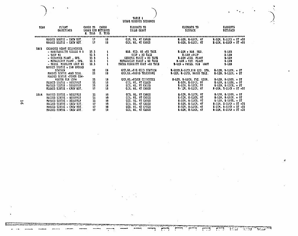
.... C7\
.) )
tEll ftlCI!! OBJrtTlVIS
CARCO TO CllCO LUX11 caB ItTti~tn II. TOllS rI. TOllS
TlUt I )
LClAI nlSSlO~ Sta~tKtE
ELtl1tliTS TO Lv;lU CUlT
m:Ulmro mneE
nmms Ul"~L ... tll
••••••• ~ •••• Z •• ~ •••••••••••••••••••••••• I ••• I ••••••••••••••••••• ~ •••••••••• I •• I •••• I •••••••••••••••••• I ••••• ••••••••••••••••••••••••••• , •••••••••
IUI:::Ill SOillt • CUV lor. 17 to 0;.:1, Rl. CT tnco I-L01. l-lU::l. n I-tot I-LLr.:t • IT .01 1I1)01£1l somE - catil lOT. 11 10 Or..1. 111. 4Y CUCO I-LIlt. I-U."G1. n I-Ult. I-Llr.:t • 1T .01
lin IllCUKlltll HtlVY DIt.lVUlts • 1I1&IT11IL:TI "~&UlE I S 11.5 BAi. ~~. IS .nl TlY.! I-Lm • lUI. roo . I-Lllt • SHOP U 11.5 Si:Jl .111 Tm 11. ttn .!llCP R-UR - Ct&l~ICS flAki , OPS. 11. S CEmuc m:rr • 111 TZ.!l1 I·L01 .etl. PLUrr I-UK - IIEiillUi,! Pll~ • CPS. 11. S HtTlllt.':CI Hl.!lT • 111 Uli:l l·lEtt • nET. rLl~ I·UR - rRESS 1I0DILITt ~11\T 11 n.s rlltsS.t;o~lLm \;,I\T .Ul Tlt:l I· lIlt • raESS. r~a. ~1IIT I·LEA
"'.lOltn somt • r II tRO\rllll SUTlOl! 11 II Cr.1,III •• rI2 m:l STlTICl I·Ltrl)l,I·lLl:t.rll t.':l. SU. I·Ltll. l·tL~, • IT
".unitD SORTIE .UD.'ttLE. J1 11 O:l:i,IIl,.UD!O TtLtSeOfE I-LL'. U-LL~. 11010 TtLt. 1,L~. I·L~ •• 1T lUIC<ED SOnTI t .FOVEA COil·
vtaTn rCR LOfll 11 11 Cl::t, HI, .rC'JtJ! cc:rm'!itll I·Ltn. I·Ll~, ri:o tCln. I·LIII. '-Ll~, • 1T nLXNtO ~Olilt • RtS~f~lt 11 10 C~, Ht. 'T C!~CO I-un. I· LlI: ... n I·LEn. I·Ll~ •• 2T Im::\tD ~omt • IltSU1PLI 11 \I O~, N1. '1 Cl~CO I·Lt:1. l-lLI:", tT I-ttl!, l·lLI .. .., •• 1T 1'.!l!XtD smlt - CUll lOT. 17 11 0;,,1. HI. 4T CllltD I· '.:''!. I·LUZt. n I·LElI. a-LL~ • IT .01
10 It nA}~tQ SO .. ilt • lESU?PLt n 11 O~. HI. 1T CllCO I·trll. I·ll~, 1T I·WI, I-U~1. t 1T ru.:mo saRTIt • ItS'JPHt 11 \Q c~,. HI. 'T CiRCa I·UlI, i-t.U!I. tT I-Ul1, I-Ur-I •• IT ftl~EO seRTlt - _lsuprLI n \I t/.n, HI. 'T Claco K-LEK, R-lL~. 'T i-lEA, S-llKn •• It IIJJ:{tD ~om t • (;. .. J tOT. 17 10 0,,1. lil. 4T CUCO I-Ul'!. I-U!:!. n a·ll/I. jl·ur.t • IT .01 ilmm scant - Cl\tII £OT. 17 11 C~, "1. 4T C~iCO I-Lt~. l-Llron, .r i·LIll. I-LL~ • IT .01 nllilltll ~ClTlt • m:,. iOT. 17 IQ Oi~. HI •• T ClIce I-LtIt. l·mC'!, 4T l-ltK, I·Llr~ • IT .01
..
'J ~ .. ' "
t::::..:..:~~..,;;,;~ ... :.:.... ...... :t:;:::~ ... __ ....... __ w~~ .... : .. , ... , , •••• I. •• ••• i ...... " ... "., i.""'~"::::':" .. tv'· . .,Jt .. n*.- , ,J3 .. , ".":-h;:"l"~"" M' ",., .. ~", ~ .. r~-~'l'" ... !'"~~~ '·"""r4'···'·'· t-:'.'~:::J ..• ! ... L": .. : .. jf._t.~':.::.;.i.:,.,:!1
:!

) nDltl --)510:1 SClItD'JU DtTllLlD LIVKCS ~lt[St ~ t . , -) mm UUNCK THt (nto IUIiUtST cuta V1. L\I,,1I rLlCI!T SPltt STlTICK TAStS tOI tLICHT LO%/LKI 1T DtPOT
Ito. D In tLI el!T c;J_ TIlt aln aa~:ss~ •• &Z: ••• 2 ••• a ••• &~, ••••••••• , ••••••••••••••••••••••••••••• 11 •••••••••• , •••••••••••••••••• '1 ••••••• , •••••• II ••••••••••••••••••• SI ••••••••••••••••••••••••••
----------••• ftAi 210S •••• -.---•••••
J1II S·l SO·lllY Lol/L81 'lOPtLLlXT SUPPLY tNlT m m rEB S·2 STS·lce [·Llklltll, .US[ tLtlltUT U 11 tS·l ~~OttD 'It'll[ ItBttl OUT , FutL) 1 Oiis 1Kn
DtLlYtU t·L~tl.C~tCt O~~ C11'0; , P~it ST1CI IUllCH S·l Sil-VLY LOl/Llll PlOPtLL1\1t~ SIlPPLI 1IXIT 110 -( 1 OTls.[·L1K:tl.lND B1St t~~~ta71 lit
HUL s·, STS-1Ct [·L1KOta,.11St tltlltNT 11 11 15-2 mJ1l~tD ,atrllt ICHttl 01T , futLI 1 Oiis 1~1l cnlvtit t-UJma;CHtCl on Clk(;Q; , IUn snet
lUI s·s SO-tLY Lot/LRI paoPtlL1HT SUPPLY UNIT m .( 2 Olll.t·Ll~tl.l~ i1St tLtr.tnTl 111
So, SiS·ACe t-LANOtR,.E1SE tLtntMT Il 11 LS·1 U~"'l(to ntult "Y-tt( O~~ , r;m 2 OTis lID CtLIV£U l·LL~ti.Cr.tCl O~~ OiCO. l r,ut sut(
JVLY s· 7 Stl-ULV LQl/lKl PiO~t~L1Ki SUPPLY ~IT 100 .\ 1 on •• t-ull:U.1.I0 uS[ ntf.th71 1U
lUC S-I SiS-1Ct [-Ll~Dta,.11SE ELtr.tNT 14 11 LS-' \:~JU~tO fltrliE \CHtCl Cat , [~tLI 1 Cry, l~ , DtLI'fUY t·LlliDtR.(?tcl O\.7 Cli.~i), , !'.An SilC1
StPT s·, SD-ULV LQl/lKl fKOPtLLlWT surrLt wltlT lit -\ lon,. [-Wilm. 00 BHt tLtlltKTI !U .... OCT S-IO STS·lec t·LlIi:ltR, .t·UI'JI/1SttNi, .OYI. •• 4 Clt'ol, 2~ LS·S 1U~:;4tO Pit?llt 1 arYl LXO t·tl~:ta. CRt,t Q~i , -..J
• 1 Tall PL !.01iI t CrJl.t-LLr.'I/asmrr, r.1tt STHl -\ 10Tls, KO'" S·II SD-ULY LoI/LIlI fROPtlLUIT S'~FPLY IHIIT IU Cr.l.t-LLl'IlI/l~Ctl(f,' [·uten I.llt;) TlIlXS- lit
Dtc S-\1 SiS·1Ct t-L1KDtl,.t-LL~IASCtHT,.O~ •• 4 Cltv 10 Hi< (WI TO Cr.>!
LS·' "S· ((lit 1l Pit?ut 1 CTh J.lO t-llX!t!. CHtCi C~'T • 1 Tal( rL lot 14 4&,SI CI'JU-Ui"J'!/lSctNi. P..ltt SHU ·1 1 elll,
Cr.J\.t-LUt"l/ASctNi.l t-u}~n I ;L'<ll nllls· --••• _ •••• -.- Yt11 ICI' .--..• ---•. --. ttl Ci til 10 Cf.'1
Jllt '·1 SD-ULY LOt/Llll P10PtLLlXT SUrPLY UNIT lID III
ttB '-2 SiS-lCC t·L1NDtl,.iASt tLtlltH! IS 21 U·I ~~l~tO 'ItPllt (CKtCl o~ 1 tUtLI 1 OTTs l~ • OtL IVtll l-lLHOtl.CRtCl O~1r Cll~O. , ftliE Siltl JU1CK .( 1 OrYs,t-llS:tl,L~ FiSt tLtntKTl
APill '·l Sll-ULY lOt/LKl ,.OPtLLlKT SUPPlt UNIT lit 111
JUt ,-, SiS·lCC t·LlIiDtI,.t·LLr.'I/1SCtllT,., cnv,.l tOIl 11 U·l liS· It lit 1\ P1EPlit 1 OTis, t-Ll~tl, l~ ~~ , tKtCI P . L. " , totl 01 lOrY tUlItlITS 101 It hys) O~1r t·LU~/1SWfT; !Uit SilCt -I 1 onl,
J1;ltt OK.'{,t·LLr.:.'tIlSttltT., [-LOOn l;l.I-:ll nw· JULY '-5 S~-ULY lOt/LHl PiOPtLLlMT SUrPLY WdlT
ttl (ltv TO c.1QI lQI 111
lUt; ,., SiS·1CC E·Ll~Otl,.B1St tLtr.tKr I' 11 U·3 ~~KKtO PRtlllt (CRtCl OUT , rUlL) 1 Oils l~ CELlVLiI t·L~tl.t~ttl err Cll(;o; , PJit STltl
StPT -( 1 ons, l·u.x~n, lIlIl USE tUl'\tlCl'1
OCT '-1 SD-ULY LOI/LSI 'lOPllL1NT SUPPLY UNIT 111 111
Hav '-I SiS-lce E·Llttlll,.t·LLf\l!llsttlCt' ,.4 UN, .1 tOll 11 u-c KS·((lltlt lIEFll£ 1 Oils. t·Ll~tl, lKa onn ; CBtCt P . L. " , \01 of lOrY tLtlmrrs lor H ('II) OJT t·Ul'\l1/1SCtlIT; !Un Siltt -( 1 OTVs,
DtC Cr.'I,t-LLr-IIlSCtlo.i,' t-lL~tl );00 TiW-rn CltV T1l om
~':""" .... ~ .. ~ ... , .. ~~ .. ~2:.:;:::~;~'-;';,.'. l:·'-'.--I"';~T:;:'~l·.·~", .'. , i'''~.;';1:,,~~('{~; ... ;i;~;·;';''~·oii )'~4~~'''·i;1;'~ ..... \0.0001-'';'':'':'~~-'''' ., ,.-; -T···i--;;-~~ __ ~"':':';';~T' -li,;-~~ .. ..;....:...:... •. jL? '- • _il·,ri.~7'···.·-":;-,,~;;.,, t· .... !'..w.'J~_2i_~ ;;.YIPIIt.p.Y,,":..t.:z::::::t!:i3

-) nBLt ) 1115SIOII SCiltDULt
lOllLKI 11 mOl)
DtT1ILtD l1UXCK KlNtrtST !
MOim! m1lCK mE ClICO lUKmST CARtO vr. LII'J(U mell1 SPlCt ST1TtOX T1St5 tCI rLICHT IiO. 1l.IOI rLICIIT tlO_ Tnt 1l.lea
'Z'.:'I •• '~SIClt ••• I&I ••• C.&'.Z.tl •••• I •• II"I'I'I'.11 , •••••••• 1&1 •• &1 •••• 1 •••••• & ••••••••••••• 211 ••••• , •• 11 ••••••••••• , •••••••••••••••••••••••••••••••••••••••••
------------- ttl' 2g07 --------------JllI 7·1 SD·ULV LOIILKI paOPELL1NT SUPPLt UNIT \00 til
rEB 7-2 SiS-ACC t-WIDta.tBASt EltllEki t7 11 U-1 lIlClI~lD .1£Pl1£ (CHICI Owi , FUEL I 2 OiVs lAD • DtLlVElt t·LLICU;CHtCI on ClllCO. , l'.nE STlet lURCH -( 1 orh.t·lllOtl.1!m USE lltImm
lPlll 1-1 SD-VLV LOllLHl PiOPELUKT SUPPLY I1I(IT 111 111
IIAY 7-4 STS-1CC E-L1KDtR,.t-lLKKllSCEKT,.4 CR~,.2 loa 10 U-1 ftS- (t1l.H I .It.llt I OTVs. t·Ll~tl. l~ O~ ; CKtCI • PL .•• 4 Ion 01 lOry tLE~£NtS o;rr t-Ll!t111SCtl:i; lUTE snct .( 10iV1. JUlit O~,t-LU"Jm5COO,' E-Lllitti I;um nus-
m Cltll TO Ol~ JUlY 7-5 SD·ULV lOIlLHI UQPELUNt SVPFLt L'lIIT 111 m
lVG 7-' STS·1CC t·LlMD£I •• E-LL!'!111 lsCthi ,.4 ca~ •• 1 In 11 17-1 ftS·l4n.111 fZEPlit 1 Oile. t·Ll~tl, lKO C~ ; CheCI • P . L. •• • 101 0 I 10n ELUltl<TS O\'i E·LLlt'lIISCtlCT; !UTE ~TlCI -( lOn" SUT Ohll.t-LlrJ'\ll~a!lT.' E·lOOIl 1;00 TilllS-
Ftl Cl!r~ TO Ct:ri OCT 7-1 SD-VLV LOllLH1 PlOPtlLllIT surHt lallT 111 lCI
.... I(~, 1·1 STS·1CC t·Ll~OtR,.t-llY.MI1SCEh~ •• 4 Cp.r~.+l 101 11 l7-4 ftS-U1hll ) lit'lll 1 OTYs. t·ll~tl. L~ C~ ; :P.ECI I (Xl P.L •• a·LLI'JI on [·LLi"JIl \SCth"T; rtlU SHtl -( 1 ani.
DEC 7-9 STS·lCC I·Ltll tLIrmrrS.IstcOlO a·LL!I1I,.Hl Tl){l ID C1C1,t·UI"::.lSCtl(!.' E·ll.:c.U 1.110 nlllS-1-10 SO·VLV LOIILR2 FiOPtLLlHT SUPPlt UNIT III ttl cm; 10 Cl'.ll 111
------------- ttli IDOl --------------
JlK I-I ST:i·lC~ t.;LlJiDtR •• USt tltlltNT II 11 ta-l U'~AIC(ED PIEPllt (CHtCI OUT , fUlL) 1 OTYs L~ • nmvm E·Ll~tl;CKECl C~i CllCO; , r~TE Silll rta 1-1 SO·ULV LOlllijl PiQPtLLlAi !7P1Lt UNIT m -( 1 OTYI. E-LUelEP.!J(l) US' ILtlUll!l tID
HUCH 1·1 STS-lCC t·L1NDER.ISASE ELtMENt It 11 11-1 UlntlXl;[O .ltPlaE (CHtCI CUT , r~tLI 1 OTYs AKa • DtLlitn E-Llh-:m,CHEtt OUT c:~r'" , IiUt STlet APRIL 1-4 SD·ULV LellLHl PROPElLlNT surnt mUl \I" -( 1 Oris.t·L~j!I,.,~ Il~t lLtnt~il 111
101.--- lanlr clew d.liltre' 10 SPlct S!llioD on ,(bedel.d rllippi, STS Ilaltb IUt lI-1 FS·(!-Ltn •• itrllE 1 OTYI. I-LIft •• 1 TAXI. Cr.M. 1[j 11
41t t 1-LUQlI l-lLr.l ; lUTE SHCl -( 10ril,Cr.M,I·LLI'JI. JUNE I-S SO·'JI V LOlltKl P~OPtLL1Nt SUFPLt ~lI1T lat lKJ I·LtM I. , i1!XSt!R CiCY TO Cr.M III
JULY I· , S:S 1 HI TUaS •• \8 Ions c I LUIUI CUCO. 11 La-4 ftS-ICIhHI flItFUE IOns 110111 TI.)(1; CK[el on Cr.:t; 47 • 4 CiCY PolU STAtl ( 'OTis.HI TUa,OtCl.UJl , teu
Aue 1-7 Sll·1!~V lOIILHl UCFtLUlCT !UP"U 1:1UT 111 or U::Ul ClICO I; , TilXSrU UtV TO Cl"OX tu ·---4 t"tV 4tlileltd aa S.S. r.s~ppl, II~ncb ---- TS lauch
~HT LI-S KS-WItHI .2EPlIE 1 ons ~~ HI 11Kl; CR!el cur C~; II r~Tt ST1tl ( IOTVs.Hl Tl~.C~,lKJ , lorl
OCT I-I STS 2 HI Tlr~S •• 11 I~II 01 L~1a1 ClICO. 14 or Willi cuea I. , noonl CRtv to Cl"JI • 4 CaEV
KOV Lt-, ftS-l4lh HI fltP Ut 1 OUs L"lll Hl Tll(l; CKtCI alii Ol'tl{. 11 ~TE ST1Cl ( IOiVl,HI TAKl,Or.n.lt~ , lonl
~tC or L\;iUl clIce I; , Tll:urta cml TO 01'J1

JrrO]I'~l~ (~r "J~~~~~~1,·:1 'i'~<''i i4l~)c; 1"~~~··1:~~~j'r~0~,~: "[~i't;~:J ;".f~"J7~;·';..,;,;:i":·~~:::~~:';~~·~~~~.h'i;.;~·:~·";·!t";·, ~~'1,~ ",' \:·\~:i\.: t' l· ,0." ",' .:: "',' •.• ';'iI" ~ '. "':"'~'
n U~O c:I
'(tH
'j )-11!lt 1
ttT~IL[' Ll~·~~K Po'.lltSf It) l~l ":1SI:1 S:%t:;.t
(U~O 1'llllltST CHc..o.,. 1n1l nl~*"I' srlcr rrITI:~ tIS'S r:1 rl'~tr • I,. rL;trr ~ TTft
"4 .'
mttt:z 1'1 tu:1 • III
.~ •••••••• at •• " ••• tt •• , •• t".'I".""""""""'.' ., ••••••• f.' •• t ••••••••••••••• I •••••• , •••••••••••••••• t •••••••••••• ,t •• ,t •••••••• ,.' •••• I' •••••••••••• ••••••••••••• Itll lie, •••••••••••••••
• '·1 so·elY LOI/LHI "OptLL1~ 1~1'Lf '~IT 111 ••••• tltv fll"ttl~ II S S III",;, 1"" ••••• • '·1 ~TS HI T1KI .• Il!t tLtr.CKT • 10 II S
a '-J S:l·~l' lO1ll1l1 mmur. Smtf ~1iIT In
1:' '.4 m J Ml TlhlS •• 6 Tel svrrLTS ••• Cltv II
. f '·S S!)·lIl' LOlll~1 rlOPtlllXT sur,,! ~IT III
I ,., m MI Tl~t .• fist 'l[~LKT • II II S
J ,., 515 hI TlKl .• 11St tLt"tXY • 11 ••• Cltv It 5
" I-I Si)·\ll¥ lOI/LMl rlcFtlllKT s~r'LT tl:T ... T .-t S:I·\:LY LCI/lY2 flOFClL1UT 5.r"1 ~IT III
t '·lI SU 11.1 mil.. I1$C tltHhi • U., • Cltv " , " '-II !1l·t;LV lCI/lXI 1iCrtlll.1r s,rrll ~~IT au :t '·Il sn III TiKI .• 11St Iltr.~" • It II ,
••••••••••••• Itll III' •••••••••••••••
I 11·1 m 1 III mas .• U 1'011 •• , tltv II
:I 11·1 til· liLY LOIILIiI n:rtLlUIT tmu tillT no I II·J STS HI TIKI •• 11St (t~r~ • I~ ••• Cltv If ,
11·4 SO·tLY lOllLMI F1CFtL1lXT svriLt ~~IT In IlL
U·S ST5 I NI WilS .• 12 TCi!. I 4 clr~ u 11 II·' ~ll·lll' tCl/LHl 1icPtLllXT s.rrLI ~~IT In
1% n·' :r:; IU HM .• un tll":['tl' • " \I S
.1 11·1 ns ;n nn .• lut lUr.OO • 17 ••• eUiI If S
C 11 , 10·VL¥ LOIHKI mmun mm PIIT III
'f 11·11 SfS 1 II T1.1S •• IJ ~~ .•• Cltv U 11·11 l~·UU LOl/1MI ri~tllllrT S~fFlT ~IT let
:r 11·11 sn Hl TU!I.. USE taw,,. I II •• 4 CI tv It S
" ,,·u to·t:, LOIILKI IlortlllKT S:"'f ~IT III
t II·U 5TS HI TiKI .• &lSt tl[~[~1 • I' II ,
tt·1 ,J.t c~.lt I ···r:'1 r.s tr.l!.:!" S!tTlt!ft::m· •• L'·1 ~~~l~.I' rl(lJJf 1 eTTI 11' It T'tl. C'I~' :71 ~~.
:umn rJn Sf'" , ImS.u TlJl.~~ ,L.O , flu or L~~:J CJt~ I. , nlZHU ur. ~ WI
Lt·, IU· 1Cl1o 1 \I .•• j:1 ~~~~~ ~tll'rlr fLI:r;s·· •
"tun I CTh A.I:l U Ttt:l. (UCI err UtI ran.:n-r ml:"~ •• r.nl ~~,:, I , 01'71 Lt·, l~JIC:" 1U iL:l.t::l un Hum.
t-L~IHU U·1 ,..;. Hil. 2 CI
Lt·, roJ..Gt:l NUtUf
n·T ;;So "'hit I
U·' re.1~:tI~ camu
U·' t::;," j !.;.:r j ~alH1Y
LII· , IO·Ul"U' ···r:. r.l I;~r.) sclTltlrlICl~~···
fHrU[ : ITh l::: 51 Wil. CH:t N1r 0C1. r~H tTL:; I lCTh.t1 '1tm,::~.C'~ , In.
tII·1 'J·lt,.,., tr L~:1.Zl cu:a J. , nu-..sru CU',; ~~ t;1;1t
m·' r;:".u:~':l tunUI ···r::~ \'7.!:::tt3 umm Ul:li~··· m·, r"s·HiMII '!t'll' 1 arl, ~~ II tltl. C!itl c:r
uu l~t';;n "L.U.:I. F'.1il 7Il~t , I an. til·, r;~.tt;;rl) III Tc.;x.UJ U~t l:.ttt;::, tlLtHU m·, Vol" t:t." I
111·' r:.7.1!::'iIl~ ttlllUt
tit·, r..;.U .. l.UI
LII·' t~!,CI:) taunt
t 1I·1t p,;. (~.t II
tII·ll \W<lot~ tum,,,
111 ., 1
til
n lU
11
U
J2
Ul
an m n
11
m n
111 us us n
" n II
III n II
11
,. r.~ J-=
f
r
I r i l t
I
... -!' :.:: ... ~, ... r: .... ... ii: -... "" ,,. ..
_t! -... ..... _ ..... .... .. -
f" ..
;; ... '"' ~ !! ... .. ~ ..
· · ~::
: ~.: -,. ....
_. --:.! .... ::t ... t·
~ .. ... ~ ... ... ... -... !; ... u_ -...... ...
!; .. 0'::: .~
:-....
"" ... .: <=> ~> ... ... v
-::
· · · · · · · ·
· · · ·
· · · · · . --..
... ::
--
-... ... -~,. ....
.. C> ...
-.
--
:.
-·
2: -u -· ~ 0;, ... .. : ... ... u ...
.. X
OJ V -... t....
-· ::
-..
--
-... --'" ... E .. oJ ... -, .. ... --'-' ...
... ,
...
... ..
. t'!
-.:. ... ;:
~ -u
... ... "" -t-.. :c
.. . ::
-.. -
--
-oJ .. 0-~ ..... to -... ... ... -C> .. -.. "" ... -u ...
.. ... ~ <:> ...
-,
:.
...
.:
... .
... -..
... on
.. ..: .. t-
..... .. ....
.. .
-...
-.. ... -
-... ... -'" u>
!; ... ... ... ... ... ", .. ... .. "" ... -o ...
.. ... ::> ", ...
-• ::
... --...
2: .. OJ
~ u ... ~ ... -...
.. :0:
.. . ::
-.c .. ...
--
--
-... -... , . ... t; ... ::! ... -~ ...
-CJ ...
-.
--
:. r. ...
;:
-= ~ -oj .. .
... ... :i t--X
OJ ... . ." ... ....
. ...
-... "" ...
.. · -:::
~ .. ...
-... .. -.. ."
'"
.. -,. .. .. · ·
.. ::
--
-... -... ~. VI
t; -... ... ... ... --.. "" .. .. "" ...
. ..
-...
:: . .: .. ... a:
. .. -...
.. :.:
--
-... --~ . .... !i< .. ... ... .. -<> -... .. ".. ... .. o ...
... , ..
-..
.. . -:::
... .. .. .. .. .. :: .. ... ... .. .. .. .. .. -
-..
-..
~ .c ... ... .... ... n -... -o ...
-...
... .. ::: ... -
i! .. OJ
or
-X
." ... ...
... . ..
-...-
-..
-. :;
.. .
.. .... - .. ~: -... -----~ .... onw .. 1;= -... ...... ... ... '" 0:> -.. ... --'" -... -- .. --0-...-.. -
~ .. .. ... !;;> •• . . c:I ....

. f"".
r .
i
... .. to U .... ... ... .... ." u
-9 ... ....... _ .... ..... t-:: ... a!
... .. ... -... ..... -.. ... ----... ~ H ... -.. c ... ~ .. ... r.: ;: -t; ... ... .. ... ....
t; ... ... ----... o.
· · · · · · · · · · · · · · · · ·
: fl...
EE: ~- . ... -: ~:: 0_: ., ::-...
... '" ... "" ~ ., .. .. .. ...
-... ... ... ... ...
--
... -_ .. -.-'" '" =0 ~~
;;
... .
---t-on
Q ... ... -
'" t-...
. .. ... .. ~
... ~ ... .... ... -::. .. , 3 .... .... ... ... <> ... -
-...
... .......... _ .. ... - __ w.,_
... ~ . i.1
--i! -.... -E a: ... .. ... '" .. -
.. .
= a:
::: .. = .,.. ..... _ .. ---...
~
'" .~ -.... s .... .... ... -o
'" ...
. .. ..! .. --
......... 2: -....
~E_F.;: '"' - -~ ... .. -4 ......... ....... .~!;;~!;; .....................
::;!;~ti~ -~ .. ... ...... ... .
~11 -J .......... ...
-~ ........ '" ... -... -~ • LJo .. c:a..~ -...,_.- . ..
;r ...... - ... _;#.;. A~;;It t ........ - __
_~t-;:t-;:';'0_0'"
..... x_%
..... > :.............
.. :::>"":JI VIt • • t-- • .-"" ....... ""0.,.
t- "'. ..... on
.... ... ~- .. · ... . ~--------
... #. ,~ ...
--
... --..
E .... .... ... -... --o ..
.. ". ...
-· .. :::
... . ... -... .... ------· .... t!~ ... 1..1'" ....... .... _ .... -:~~
{;t.1I;:
~sa .... !: =~": .... -... _0 ... --VI- • -~- .... ... ':11".:l1li t- __
_ ;;t,:.J:.e,,-.... '" ... .... :-..... ... 4 ... :> ..,
• '0-w> n '" .. '" .,..
· .. ---tOJ .:.
-...
.. .. ~ ... &: .... .... ... ... ..... ... ..
.... .... .,.
-..
. ...
~ .... -:~ .,.
E .... .... ... ... C> .. -... o ....
.... ... U
-... ... ... .... ...
:::
!:: ~ ... .. --~, '" ~ ... ... .... ... .... <.> --... 3 .. co ...
... ..
---II: ...
..
...
-. ..,. ... "" ... ..
-... ...
-
--!'l · i2
... · --...
~ .. :
--.. -.. ... ... • .. .. ..
-·
.. ... ..
... -
--
-... --=> ... !; ~ ... .... ... -u -... .. ~
'7 -... .... -=
--
· i2
· -:::
:! ... ... ... ... :..r. .... .... ... ,.
-·
... ..
!:: ii -... -... : .. ... E ... ... ... -.. .. -.. ., ..
.... . -
--U; -. ;;!
.. u -.. ---.. .. .. ." ... • --.. .. .. .. -! -.
., ... ::~ p.... ...... .,.
:::
... -:;
...
i ... ....
.,.. -:.c: ... ... ... ""
'" ... '"
. -
--
~ .. .... ... ... ... co --... ~ -C> ...
... . -
.. -
· 12 .. .;. -..
.. ~ .. .. --.. .. .. ... ... • --.. -.. • .. :. .. · · · ·
u ... .,.
•
/
('.) Co., C':l
CD ,: .. '-
C':l C :J -J -CO
(;) C C 0 (I) ... C)
Cl.
r ,
11
16
14
12
10
• 6
4
:1
200S
Estimated Manning Lavels of Lunar Base
2006 20;,1
Year
Fiaurc 5
2:.114 201'.;
E. l
!

',~
iI' ! I'
~ -'f
4.4 Lunar Space Transportation SYBte~
A Get o! vchiclc~ deoigned to perform the lun~r sp~ce transportation function was defined and robed. The elcr.lents of the nyntem were thoBe defined in the JSC Lun~r study (Reference 1).
The systen was decigncd to deliver a 17.5 metric ton unmanned payload module to the lunar 9urface, or to deliver a manned rnodul e pl us iln ascent vc.'hicl e to the sur! ace. The 07V's nll return to low E ... .Irth orbit. It was ilfiBumed that man-rated aerobraking orbital transfer vehicleB arc available.
The Delta-V budget for the sizing exercise is given in Table 3.
The 5caling lawB for eBtimating inert weightB of propuloive ntages ilre given in Table 4. These were provided by JSC (Ref. 2) as an agreed upon representative ~et of inert weights. In addition to the inert weightc, each propulsive stage was considered to have 2.S% of its propellant weight left at burnout for reserves and residuals. ThiB W~3 compoGed of 1\ of the propellant as trapped and unavailable and 1.5' as hardware reserves for such items as mixture ratio errors, I5p vnriation, etc. Hission reserveB arc included in the delta V budget.
The Expendable Lunar L~nder was first sized to deliver the 17.5 metric ton baGe ~lement fror.l lunar orbit to the lunar surface. Then the AOTV's were zized to deliver the fueled lander plus payload to lunar orbit using two stages and returning empty via aerobraking. 'l'he other elements were then sized to accordingly.
The resul tant set of elementt' of the lunar space transportation system are given in Table 5.
4.4.1 Sizing The OT''' - Hulti-Stage Rationale
The Aerobraking Orbital Transfer Vchicle COTV) along with the Shuttle, the Space Station, and the small OBV will be preexisting elements of a generalized space transportation syster.l. The OTV's are sized initially for delivery and retrieval of satellites to Geosynchronous Earth Orbit (GEO).
Such an OTV is well suited to lunar transport since the delta V from the Space Station to GEO is almost exactly that f rom the Space Station to lunar orbi t. Returning f rom the /1oon with aerobraking actually takes less dc:lta V than the same return fro:n GEO.
Lunar operations, however, generally req_ire payloads in lunar orbit that arc several times as large as the equivalent GEO payload, because half the mass in lunar orbit is lander weight. Therefore, an OTV sized for GEO operations may be only half as large as one designed for single Btage lunar operations. One solution is to use more than one OTV at a time for e~ch lunar mission.
If the 01V's are de~igned to be ·stacked" into a multi-stage vehicle, then almost any size payload can be delivered to almost any delta V desired (such as for high energy planetary missions)
23
•
r"-. !
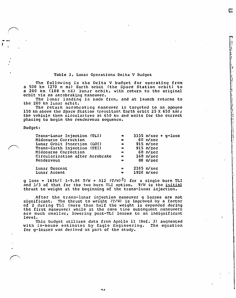
Table 3, Lunar Operbtionn Delta V Budget
The following in the Delta V budget for operating from n 500 km (270 n mt) £<1rth orbit (the Space Station orbit) to a 200 km (lOa n nil lUn.Jr orbit, with return to the original orbit via an aerobraking maneuver.
The lunar landing in made from, and at launch rcturnD to the 200 km lunar orbit.
The return acrobraking maneuver in targeted to an apogee 150 km above the Spacc Station (reDultan~ Earth orbit 25 X 650 km) 1 the vehicle then circularizes at 650 krn and waits for the correct ph~nin9 to begin the rendezvous sequence.
Dudget:
':rans-Lunar Injection (TLl) .. 3155 m/ncc + 9-10n8 Midcourne Correction • 60 mlnec Lunar Orbit I!'lsertion (LOr) .. 915 mlzec Trans-Earth Injection ('i'EI) a 915 mlscc Midcourse Correction a 60 r.Vscc Circularization after Aerobrake .. 160 mlsec Rendezvoun a aD mlnec
Lunar Descent 0: 2165 r.Vsec Lunar Ascent .. 1920 mlnec
9 loss II 16351 [ 1-9.85 T/H + 512 (T/h') 2) for a single burn TLI and 1/3 of that for the two burn TLI option. TIN in the initial thrust to weight at the beginning of the trans-lunar injection.
After the trans-lunar injection maneuver g losses are not significant. The thrust to weight (TIN) is improved by a factor of 2 dur i ng TLI (more than hal f the weight is expended during the firnt maneuver) while at the same tir:1c subsequent maneuvers are much smaller, lowering post-TLI losses to an insignificant level.
This budget utilizes data from Apollo 11 (Ref. 3) augmented with in-house estimates by Eagle Engineering_ The equation for g-losses was derived as part of the study.
i.
t: .~
?: L.
I~ ., ., i
','
I l

,
f'"
, ,
. . \
. -,
: .
, -L
r
Table 4, Space Tr~nsportation Vchicleo Scaling Laws
The inert weight for the Orbital Transfer Vehiclen COTV's) and the variouu propulsive elements of the lunar operations transportation oyntcm are given ao follown:
Stage Inert Weight s (6 + n • Hnl + ~D • PLaero \ 010
(l - 'D) Where
and:
A ..
A os
A ...
Wp a Stage Propellant Capacity (in kg).
PLaero • the maximum amount of payload that will be carried through the aerobraking maneuver <in ',g).
AS a thc ae:obrake mass fraction.
a .15 for this study.
2279 kg, D = .04545 for cryogenic otagcs
2352 kg, S a .0228 for pump fed storable stages
2454 kg, D a .04253 for pressure fed storable stages
The above are for space-based vehicles. For Lunar Landers an additional 2\ of the maximum landed weight (including paylo~J) must be added for landing gear.
These data are from Reference 2. Sections 4.6 and 5.8 examine the sensitivity of some of this study's conclusions to changes in some of these numbers, such as Isp and inert weight •
25
l' . ~ ~
:) '.' ,0

~. r
STS tltlltHTS
TAItt 5
L~1U1 SP1C[ T11~srClTITla~ 5TSTt"
[Lt~thi CtStEIPTICK tLtllrk~ r~tTIC. IKj CtSltK COlLS
•••••••••••••••• , ••••••••••••••• c •••••••••••••••••••••••••••• " ••••••••••••• 1 •••••••••••••••••••••••• ,
ElSE [tlP.t~i cc~ ReOULE
t~1 L1~OIHC K1~t~ "~'~lr IlLIt'II
[·U.-xCKti
ltIC!211!KC 0!81TIL Tl1KSr[1 YtHICl[ IlOrYl
Ul1sutE L~1U1 wl1lu/m'XCl!tl II - WI!
ItUSllt[ tl1tl1 tlKnlKC ""NNtD ~ODUL[ (i· L~I
niCE Or.'!
Kl TUKSrEl TAn
t •• ,\~ • II I • Cillelil • , 'I. CC~OM lVXll HOUSIN: LAj/CI V'I~kl .1' S a II. LltOllTeI! ~XIT
01 ••• 1., • I 2 a • K'I~'I • 1 I VfI~~1f
elll Ocl • 1 I a 101 UI.~lt rr',llllll • 11 , a 10. LOlltMl 1lOrtlll~1
UHI.-'ULt LL1lU wnu O[SI'KtO TO CtllVtI If S 8 101 TO l~NlI S\;IUCl
It!;1~ • , 'a . Dlu.ltr • 1 'a ~~~'!LE TO ClUT Cltv or , TO Vtlibl • 1 IS I I •• (~IIt • crt~1 l~Kl. S~!rlCt, l~' lrrJ.N ••
L:IIIT[O Llrt surfelT
DI.I,ltr • 1 , 10 5 • 1!'I;hI • 1. V.I;U,
eara C,\ • 1 , S ICD U,.lll 'r."II.DI • 5 • lei n')!, ftD,SteIULE Pro,.llnl
Llt,l. I 1 'a ; DiaDlltr • 1 • Dlluttr • i •
V.I;.I • $.5 D lei (VII. 4 crlv)
DIII,I.r I 11 1. (A,ro S~I.14) lUlth • 5 D
Vti;U. : E:ID Oal • 1 C • tCI USI.I. Pre,elilftl • 41 • tOft
LOI/1H1 'ICi,ll.ftt
Olll,\.r I 10 I ; N'I~'I • 1 D. VII;hh:
S,re Cal. 5 1 • 101 UI.bll PIOF.III~I • 11 1.loe
LOI/LH1 PrcJ.III~1
L.t;n • S. ; !lllstltr • 2 , Il. V'I~bl IS. 101 IVllh , CltV)
L'D~I •• 4. ; Dill.tel • ] • Vllqhl • I • IOD (~Ith , cl.vl
Vllett • 57 co • V, i ,hi I
rapl, vI .\ • teft fvll ~I • 5 I to:
··1i0T KEeStD··
tl'[~~111t ~At~tHtR TO ClllT ll~ FI" S Ion ;\YLOlC rlc~ LtHll SUlfACE TO lUHll CRIIT
CRrw r.~OUl[ fca crv, TO Cl!lf rtRSc~tl fl:'" 011 IT 11 CIIIT ·~!fIlT strut [VJr.OXl'!!l,~ ···REilSULt···
or. SIltO TO CHit£! 15 • tea TO LUlU!! calT l .. :l it1n:>l [IIFTY USI~C TVO orv, !07~ ~[7~?'.tD IT ItROiilllNC •• It~Sl&LE··
Ll1l1i Ilst~ '[HIClt rca TllKSrOKT fp.cn LUhlR SURf ACt TO l.1l11 CiSlT 'Xl UCt • CSllt~ lll"..lR flOC~Cto OlYC[~ ttSlc~tD fCI 17.~ 11ft PL tCVM, Q UP ··01·U Ion FL t{)'r"ll, 7 I ~l l'l . • 1 S tin Tl~ Of lHZ IS 1LSO C1tRIEO nv~~ eM [lCY Ll~jIHC
L~1UK 51stD ~~~~tD ~'~ULt f~! CSt VITH I·L[ft. n:iHAl CREV '.~jl 10
URCtR Cit'! REfUctPlUIT. rOI au lill TRAl\SFGn or CH"S IX IU~JIt LI:!1IR USE CfEP.lTIOKS HCR~Al tRtw •• f~l I.
TAKl cr LIOUID HTCROCtN FurL rOI R·W! (\11TH Llr!HP. 011 • CSE t£llvtltD TO lr~lR SURFAct STOR1C[ [lCH fLICr.i
•••••••••••••••••• L1UNCH VEHICltS •••.••.••••..•..••
~K111TU I STSI
SHUTTLE/1rT C1geO CIllltR (STS·ACC)
PL 10 SPice Stat len • 15 a lOB
fL 10 Spat. Stillea • ZI • lo~
SHUTTLE Dmvro lrll."I!lID!t:l LH1iCH UtllIl lOIIL!!! to SPiel YEHICLE (SO·ULV) St.llca • 1:0 • tca
26
1[~5AElt LAUNCH VtHICLt rCR VALUABLE CA~COS AND FtlSOKXtL
SKliiLt VITH I CUCO CC!!PUnl["~ ON AfT [~O or [ITt~~AL TA~l ·fe! OV[RSIZE Cllces·
,~"I!l"~rO llI:NCH[R OESlc~r~ USINC SH~TTL[ tLth.his,··\:sro rOR LA~NCHIHC LClltH! fIOr[tLlh~ TO O~JITAL STOllcr CEfor
.':

f~ 1. ! .
by simply stacking a suf!icicnt number of ntagcs. Lunar base operations provid~ enough traffic so that some
OTV resizing is justified and cost effective. The OTV'n designed for G£O have tended to be nized at around 30 metric tons of propellant CL02/LH2)' The name banic vehicle could be sized to support the dcsireo lunar operation!; in a two st.lgc configuration simply by enl.lrging the propellant tanks by about 30'. This could be done for the JSC concept illustrated in this study (Fig. G) uithout chclnging either the aeroshell or engines and with tanks that are still deliverable within thc shuttle bay.
Trying to enlarge the OTV to support lunar operations with single stagen uould require il new deGign. For this size range, two stage operationn appeclr to be more efficient thcln single stage.
Consequently, the AOTV was resized to perform the lunar mission model with two (tandem) utages. The result was a vehicle of 42 metric ton propellant capacity.
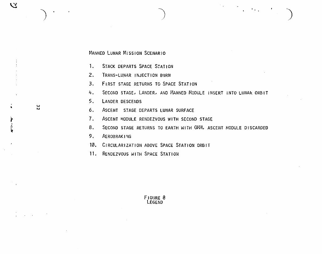
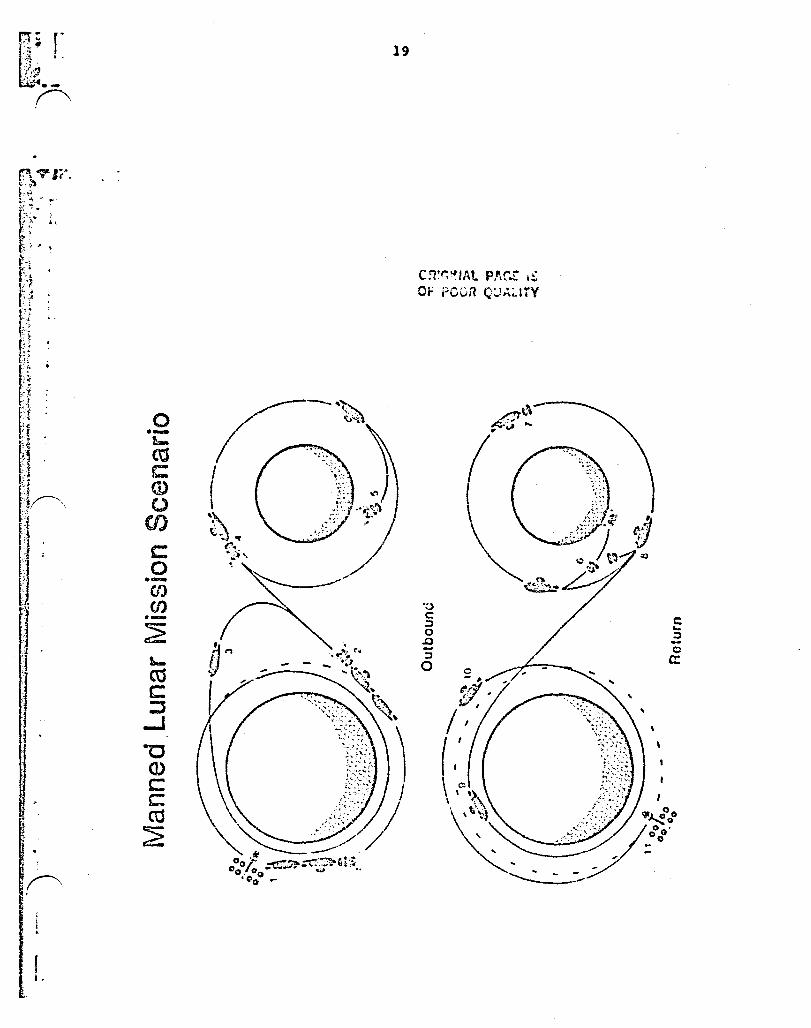
4.4.2 Mission Scenarios
The mission scenarios divide into two sets once lUnar base construction begins. These are unmanned heavy delivery missions, and manned rotation/resupply missions. These are illustrated in Figures 7 and 8 respectively.
The unreanned heavy delivery missions (Fig- 7) deliver the major base elements to the lunar surface. Two large aerobraking reusable OTV vehicles, used in tandem as a two stage rocket deliver the 17.5 metric ton base element, mounted on an Expendable Lander, to a 200 km lunar orbit. The lander then provides transport to the lunar surface where it remains (Fig. 9). The OTV stage returns to earth at first opportunity.
For a manned mission (Fig. 8) two OTV's deliver an OTV Manned Module (OMM) containing the crew plus an Expendable Lunar Lander loaded with a Lunar Lander Manned Module and an ascent stage all to lunar orbit. The OTV and OTV Manned Module remain in orbit while the lander descends to the lunar surface carrying the Lunar Lander Manned Module with crew and the ascent stage. After the appropriate mission stay time (7 to 14 days) the ascent stage returns the Lunar Lander Manned Module to lunar orbit. The vehicle performs a rendezvous with the OTV and the crew transfers back to the OTV Manned Module for return to Earth via aerobr aki ng. The Expendabl e Luna r Lander, ascent stage, and the Lunar Lander Manned Module are all discarded.
After lunar ourface 02 production haG bct.Jun, one or more r~usable single stage Lander/Launchers are delivered to the lunar surface. The scenario is then changed such that only the payloads and a large tank of liquid hydrogen fuel for the Lander is brought from earth orbit.
27
:.-.;.. .. :
: ~ ~
:'1 I. , ;
'~i ., , ...... :> .. ,
•. ,,!
; -~
<~ ,
x .. -:~
·.·:l ;;~~ .. , ~ .,
,. ·:t" .,
y
" :}'
, :f-.;.~
~ -,
"' ;;; t
":~ ;;
j "j , 1 'I 1 ! 1 1
i ,
The Lander is kept on the lunar surface and provided with liquid oxygen (6/7 of the propellant ..... eight) from the lunar oxygen plant. This reduces the trans-lunar transport requirement by nearly half. The OTV delivers the payload and a full H? tank to lunar orbit. The reusable Lander CR-LEM) then launchei and rendezvous with the OTV. The payload, OTV and H2 tank are tranoferrcd to the R-LEM and the OTV returns to Earth. The R-LEH lands and the HZ tank io removed to a storage depot from where it is used to fuel the R-LEM for the next flight.
A reusable Lunar Lander Manned Module (LLMM) is kept at the lunar base. For manned missions it is mounted on the R-LEH to transport personnel to and from the lunar surface. For a manned fl ight the OTV del ivers crew ir:. an ONM plus an H2 tank and any extra payload to lUnar orbi t. 'rhe R-LE~1 wi th LLHM aboard launches to lunar orbit carrying the crew to be rotated and rendezvous with the OTV. The cre ..... s ~3ch transfer from capsule to capsule and the payload and H2 tank are transferred to the R-LEM. The fl-LEM then lands with the replacement crew and the OTV returnn to earth with the OHH and the returning personnel. An H2 tank is delivered for everv R-LEM mission.
The R-LEH, LLMM, and H2 iank arc illustrated in flight f'" configuration in Figure 10. . . The OTV carrying the OMM is shown in J:"igure 11. liott! Lhe
position of the OHM within the entry shado ..... of the aeroshell. All payloads and material carried through the aerobrake phase will be mounted in this position.
4.4.3 Earth Launch Requirements
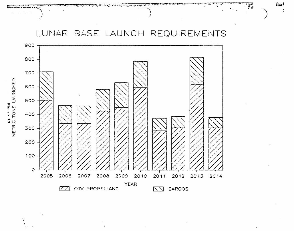
Figure 12 sho ..... s the amount of material that must be delivered to the Space Station each year to support the given lunar base build-up scenario. Figure 13 sho ..... s the resultant build-up of material on the lunar surface. Note that the vast majority of the mass involved is LOZ/L1h. This includes the propellant for the lunar lander as ..... ell as that for the OTV. Using the shuttle as a tanker to launch such massive amounts of cryogenics to orbit is neither prudent nor cost effective. At 25 metric tons per flight, 16 to 30 tanker shuttle launches a year would be required to support this effort.
An Unmanned Launch Vehicle designed using shuttle elements (a shuttle derived unmanned launch vehicle or ULV) should be developed as a tanker. Such a vehicle with a stretched External Tank and lengthened Solid Rockets Boosters should be able to deliver a propellant depot module of about 100 metric tons propellant r.:apaci ty. This would reduce the lunar base Earth launch requirements by between 12 and 22 launches per year at an annual savings of from I to 2 billion dollars. In addition, the total launch rate is reduced to the much more manageable level of approximately
~,ne per month rather than one every two ..... eeks.
28
. !
" ,'-1 :~~ ? ~ '~, r\·
{ \ !. , >.'
".: .. . . . . ,~ "'"7'\" .~
~! , I: -'
.;'!
1\ '.',..
.~~-7 ;; . . -~
, ~; ::;,~ . ., .~ -j
:1 -~ -j 1 ~
J
';", I .~ ..
f i I ,
Figure 6 AOTV
29

w o
"
) )
UNMANNED LUNAR MISSION SCENARIO
1. STACK DEPARTS SPACE STATION
2. F,RST STAGE BURN
3. SECOND STAGE BURN
4. FIRST STAGE RETURNS TO SPACE STATION
5. C,RCULAR,ZED IN LUNAR ORBIT
6. EXPENDABLE LANDER PLACES COllJ.toN MODULE ON THE LUNAR SURFACE
7. SECOND STAGE RETURNS TO EARTH
8. AEROBRAK I NG EARTH ORB I T I NSERT I ON .
9. C,RCULAR,ZED ABOVE SPACE STATION ORBIT
10. SECOND STAGE RETURNS TO SPACE STATION
FIGURE 7 LEGEND
.. ')
• ';";'::":'J;28..:.~".~,;.:_,~~~· .. ::.::::::.~:w.,::, .. :",~:;~:::".~~.~>\;~';'~'.,.~".;:~;.;:.~/ .. ;;.\,:;;.;,.c.;.,.,';:~";":"~;':""';'~;"'':';f:''''~~'':.l'~;:::;;';';~;·\''·';'''·''· .. >I;"'~';'·;"';";;"';;',:··i ... ,··::'·;:.~,.·~. ··':·'·{i':'/·;'·''"'~·:).:·.;:·;t''3

0 --t.-ea C <D 0
CJ)
r:: 0 --(J)
f"'. rlJ . .,-2 l-ctS C ::J -' -c (!) c t: C\1 E c:
::>
r-\ I
O~ .... ("4
"C C :J 0 .0 -:J 0
c':;· .. · • .:. OF h ... ·-·\
Figure 7
31
c ':J -(I,)
ex:
1-..~ .... .~ :; , <t
.. (
,'';'
~
"J
w II IV
't . ~
) • t
MANNED LUNAR MISSION SCENARIO
1.
2.
3.
4.
5.
6.
7. 8.
9.
10.
11.
STACK DEPARTS SPACE S7ATION
TRANS-LUNAR INJECTION BURN
FIRST STAGE RETURNS TO SPACE STATION
SECOND STAGE, LANDER, AND MANNED MODULE INSERT INTO LUNAk ORBIT
LANDER DESCENDS
ASCENT STAGE DEPARTS LUNAR SURFACE
ASCENT MODULE RENDEZVOUS WITH SECOND STAGE
SECOND STAGE RETURNS TO EARTH \'lITH or:Ii~, ASCENT f.lODULE DISCARDED
AEROBRAKI~G
CIRCULARIZATION ABOVE SPACE STATION ORBIT
RENDEZVOUS WITH SPACE STATION
F I GIJRE 8 LEGEND
-)
r t.
o .-!0-ro r= (J) o
CI)
c o --en en --~
19
C:t~~IAt p}\r.r .:: Of PC0i"l Q~~~ITY
~ C :l o .0
:l o
c: ~
:l -~ c:

I r-,: t~~ .. f-
,.
f -.. -, . , • t •
20
o
o ~~ __ ~ __ ~~ ______ ~~ ______ ~-J _____ ~
J" ••• -y!..,~
: /'f .r .. ~ !. ,r-
,".:- ..... : .~~ . . ",. .. (.:
'.t. ,-' .i'''''('1-.. t;~ fl.·'/~ ___ .
:",.~ .,-.,.
Expendable Lander and Common Module
Figure 9
I
20'

;~, - ,
1-
!
••
I 23'
I !
R-LEl\~ and Large H2 Tank
Fiouro 10

-.... ~
". ;".:._.,,; \I""·~.~ •• "
OTV w IManned Module
Figure 11
i.Ji ~--:..:!:_ .. .:,::.::~~4. t~,~~~ ... ""c.m., ,f ", f •• 'II;"".':.' ... ,s.".~.f;,.JP*'*J:'..; {_~ ... ~. t, ... ~'~.,-:..:~J~.~~~ .... ....,.,.~, ........ -;\.:I.!~~~.;...;..;,i ... "'i~.; .• ",*f""~I~"'\.r::rr.:r) ..... "".~1,·,..,w;:t,J;"(4 .. '2,{; ... IKl' r;;$H·:.:::v:· .. Y.',~ .I;"$'!'" . """' ... ~ 0 t ~ --i~!." i '5 t .• ~~ L:'h~i
j) ", ''')
"
o w I () Z :::l 5
5' (j) : Z D 0
I-.. \)()
a:: IW ::!
\ ,
LUf\JAR BASE LAUNCH REOUIREMEf\JTS
900 ,---------------------------------------------------------~
800
700 h < . i
600
500 -J ~. ) ~
400
300
200
100
O [// [e'/ r,'? [L/ [LL [LL /L ['/ 'd' t//-J j r iii , iii i
2005 2006 2007 2008 2009 2010 2011 2012 2013 2014
YEAR lZ2J OTV PROPELLANT ls:sJ CARGOS
\
If"'L"":):~. ,~,M<. ~-I,J •• ( ,', t~·~.,,:wt '~! 'v?'"'''' ... ,1 :of ti. ,<*::t·~.~~·>~.;--t .. !"_'7f'~r:s; ... '""k~1,':.."j}·,,; ... ·:h .f .. <'f ... ,C;i..c~~;.:w~"'12l: ..... " .~,..t .... ~""~:..tw:.."! .. 1I6ld..w .. ~~!l.'~;t,l;~;,,, .:: . __ ::J..'''::';L ~-... f:r"'7.'~~ti':l.ii~--;:::c-~-r--· ... ·,,~--~ ,:-.,-- "'- r, ., .~~~ ',.~~
.." :c c ... ('.)
..... (..)
(/) z o t-: ::!
.. ...J 4: n:::: w ~ == o W t~ ...J :) ::: :)
) ") t\~ATERIAL AT LUNAR BASE
AT YEARS END 900.-----------------------------~------------------------~
800
700
600
500
400
300
t3 200 4:
100
o If?' fiL './ LlL /f' 'i' '.< 'If (I' ',I'
2004 2005 2006 2007 2008 2009 2010 2011 2012 2013 2014
YEAR
..
tzZ] BASE ELEM ENTS ISSl OTHER PAYLOADS ~ SCRAP
.. ")

, r ~
'.,,-z ;. ~\ ; • r 1 i ,
.1 ." . ,-,
. ;
:j -I ,I \
;j
H ,1 :1 ~ .
.
!
A second, but important factor i~ safety: the risk of many launches of a billion dollar manned Shuttle with a cargo bay full of cryogenic propellant. The loss of a ULV full of L02/LH2 would be spectacular but not catastrophic •
The large 100 metric ton propellant units delivered by ULV could be plug-in-depot units so that extensive propellant transfer from the tanker to the depot would not be required. Section 6.2 discusses propellant storage and transfer in more detail.
4.4.4 External Tank - Aft Cargo Compartment CET-ACC)
The first 16 or 17 lunar missions use ~n Expendable Lunar Lander that cannot readily be designed for delivery within the shut tIe Col rgo bolY. The flight frequency of those missions is high enough that assembly of the vehicle at the Space Station might produce an unreasonably heavy workload. In addition, the Shuttle payload bay threatenn to become so seriously volume limited that an extra Shuttle launch per lUnar mission becomes a real possibility.
O~er the last several years various studies have been carried out under the guidance of Harshall Space Flight Center CMSrC) on the possibility of an External Tank Aft Cargo Carrier (ET-ACC), a cargo space attached to the rear of the Shuttle External Tank to enolbl e del ivery of oversized cargo elements. This rcqui res that the ET be carrice into a stable orbit and deorbited at a later time rolther thiln dropped sub-orbitally af, is nominally done. A pre-assem~led E-Lander can thus be launched, and the payload bay is free for other cargo. There is, however, a loss in shuttle payload capolbility of about 3 metric tons.
The E-Lander design illustrated (Figure 9) fits within this aft cargo compartment. The number of flights (16) justifies the development cost of the ET-ACC and the savings in shuttle launches should more than pay for those development costs.
An alternate solution would be to launch the E-Lander on the ULV flights. This did not manifest as nicely but may be more cost effective.
39

\ . I: f" I,
t r~ ,
t
4.5 Impact of the Lunar Missions Upon the Growth Sp~ce Station.
4.5.1 Summary
During the 10 year period of lunar operations examined the Space Station supports 68 lunar sortie3, 43 of them manned, requiring:
o 102 launches - half of them Shuttles and half unmanned tanker launches.
o 136 AOTV sorties.
o 270 OMV sorties.
The Space Station must provide propellant storage and transfer facilities (propellant depot), assembly of the mission stack, payload checkout & integration into mission stacks, maintenance and checkout of veticlcs stored on orbit (OTV's, OMV's, OHM's), flight control (rendezvous, proximity operations (. docking), personnel billeting, and temporary payload storage.
Hardware required to be added to the growth Space Station includes:
o
o
o
Permanent basing (hangars, storage and shops) for 4 OTV's, 2 OHM's and 2 OMV's.
Gantries and docks for preparing mission stacks, up to 40 meters in length, of 2 OTV's plus a Lunar Lander, plus various manned and unmanned lunar cargo elements.
A propellant depot for cryogenic L02/LH2 propellant with capacity of at least 2 tanker uniEs of 100 metric tons each.
° A propellant transfer capability to perform a measured propellant transfer from the depot to various venicles in the mission stack at the assembly docks. A rate of 5 metric tons/per hour is required to complete transfer in one 24 hour period.
o Tempor a ry stor age for lU'la r Ifehicl es and 20 to 3 a tons of lunar payload.
o An addi tional habitat module as housing for the oddi tional Space Station crew and temporary billeting for 4 to 6 transient lunar base personnel.
40
I I .
'.

l ' 1 i '.
~. . I • I.
!I
i :; , ! •
:,. ~ ; .
" (t ,.
o An estimated 20 kw of continuoua additional power with related or greater heat rejection. 10 kv depot cryogcnic refrigcration, 5 k~ for the extra habitat, and 5 kw or more for gantries.
Space Station identified ollnpouer requi rementa are 14 manweet:a per lunar Dortie. Thia brcaka down into 5 manweeks of OTV aupport, 5 mnnweeka atack aSflembly & fuel ing, 1 rnanueelt (l1Ver~ge) for manned vehicle (OmU cupport, and 3 manweeks for flight operations l1nd oav Dupport. Thece operations require a minimu."ll extra crC',l complement of 2 persona. This could be doubled by uniuentified required taska.
4.5.2 Space Station Hl1rdware Required.
The lunar missiono require 2 OTV's per aortie uhile llvoraging one such Dortie every eight ueeka. A minimum of one e~tra OTV will be required for replacement to maintain a regular schedule. If tvo e:ttrl1a arc used, t\-10 otllcka could be aoacmblcd oirnultnneou61y for those periods \~ith very cornpt"csned mianion achcdulcs. Thin gives rise to an operational OTV fleet sizc of 4. Such a fleet would also allow time for e~tensive scheduled maintenance and overhaul while still protecting against unschedulod flight cancellation. Schedule will be much more ioportnnt in the oupport of a manned lunar base than in present STS operations. In addition to lunar missions, this fleet \lould b~ involved in planetary, GEO, and other missions.
Similarly, at least 2 Omt I s are needed for schedule protection as well as for possiblc rescue operations. rne small OFtV units will be used up at a rapid rate and they viII probably make the round trip to Earth at a fairly rcgular rate. However, at least 2 should be on station at all times.
Permanent basing for these vehicles should include han9ar facilities for meteoroid and orbital debris protection, thermal control, and routine mission preparation. Shop and m~intenance equip~ent for a complete overhaul of the OTV vehicles and at least routine repair of the other vehicles will be necessary. The OHM'S and OMV'a can be returned to earth for major repair but the OW's would be too bulky for routine Shuttle transport.
Gantries and docks will be needed for preparing mioGion stacks. These stacks will typically consist of 2 OTV's, a base ele~ent and an Expendable Lunar Lander. For the manned mission the base element will be replaced by a Lunar Lander Manned Module (LLI-t'1) on the lander and an OHM carried on the ON. Thece atacka will be up to 40 meters long and when fueled mass as much as 133 metric tons.
A propellant depot for cryogenics propellant (L02/LH2) will be necessary. The proposed technique is 100 metriC ton depot units launched on unmanned tankers. The depot \'Iould need the capacity to handle two of these units at once, since even a half emptied unit would have to be supplemented by a second full one before a lunar Bortie could be supported.
41
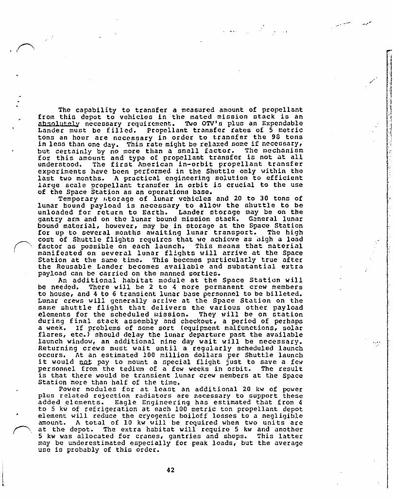
.. ~
I , l
The capability to transfer a measured amount of propellant from this depot to vehicleo in the mated misoion otack io an abllolut.e.l..¥ necessary requirc:ment. Two O'lV's plus an Expendable Lander must be filled. Propellant transfer rates of 5 metric tons an hour are neceosary in order to transfer the 90 tons in le09 than one day. This rate might be rela:ted aome if necesoary, but certainly by no more than a omall factor. The mechanism for this amount and type of propellant tranofer is not at all understood. The first American in-orbit propellant transfer experiments have been performed in the Shuttle only within the last two months. A practical engineering solution to efficient large scale propellant transfer in orbit is crucial to the use of the Space Station ao an operations base.
Temporary "tor age of lunar vehicles and 20 to 30 tone of lunar bound payload i9 neccosary to allow the ohuttle to be unloaded for. return to Earth. Lander storage may be on the gantry arm and on the lunar bound mission stack. Ganeral lunar bound material, however, may be in otorage at the Space Station for up to several months awaiting lunar transport. The high cost of Shuttle flights requires that \Ie achieve as ,1igh a load factor as possible on each launch. This m~ano that material manifested on several lunar flights will arrive at the Space Station at the s~e time. This becomes particularly true after the Reusable Lander becomes available and substantial extra payload can be carried on the manned sorties.
An additional habitat module at the Space Station will be needed. There will be 2 to 4 more permanent crew members to house, and 4 to 6 transient lunar base personnel to be billeted. Lunar crews will generally arrive at the Space Station on the same shuttle flight that delivers the various other payload elements for the scheduled ~ission. They will be on station during final stack assembly and checkout, a period of perhaps a week. If problems of sorne sort (equipment malfunctions, solar flares, etc.) should delay the lUnar departure past the available launch window, an additional nine day wait will be necessary. Returning crews must wait until a regularly scheduled launch occurs. At an estimated 100 million dollars per Shuttle launch it would o..o..t pay to mount a special flight just to save a few personnel from the tedium of a few weeks in orbit. The result is that there would be transient lunar crew members at the Space Station rnore than half of the time.
Power modules for at least an additional 20 kw of power plus related rejection radiators are necessary to support these added ~lements. Eagle Engineering has estimated that from 4 to 5 kw of refrigeration at each 100 metric ton propellant depot element will reduce the cryogenic boiloff losses to a negligible amount. A total of 10 kw will be required when two uni ts are at the depot. The extra habitat will require 5 kw and another 5 kw was allocated for cranes, gantries and shops. This latter may be underestimated especially for peak loads, but the average use is probably of this order.
42
-.-
/
j
1 :j ; "I
1 I 1 ., I j
_l 4
.1 ,j
:, ~
";
r

I . i . .
\
! ~
'f" ..
L .. I
j C
,
4.5.3 Space Station Manpower and Functions Required.
The schedule requires a lunar sortie every eight weeks on the average. Manpower estimates per lunar sortie includes the following:
o
o
Total OTV turnaround and maintenance of 24 man Qn~B per lunar mission.
OTV turnaround operation - 70 manhours per OTV.
OTV scheduled maintenance - 70 manhours for every 5 OTV sorties.
OTV unscheduled maintenance - 90 manhours for every 10 OTV sorties.
Trafflc control a 8 man days per lunar sortie - 4 major arrivals/departures requiring OMV sorties per lunar mission. Each will require 2 crC\<1 members for at least one shift or 2 man d~ys each.
o Stack assembly - 3 or 4 days operations for 2 crew members - 8 maD days.
o Propellant transfer - 24 hours for 2 crew members - 6 man Cays.
Total = 9 man wecks per 8 week period.
This requires at least 2 extra crew members for identified tasKs. This will probably at least double for unidentified tasks.
4.5.4 AOTV Stack.
The stack of two AOTV's carrying an Expendable Lunar Lander and a Common Base Element is illustrated in Figure 14 departing the Space Station. Note the om returning to the Space Station alter having maneuvered the stack to a safe distance. The AOTV illustrated is the JSC concept in which the tankage and support structure is tucked inside the aerobrake shell and the engine thrust is applied edgewise. JSC estimates that such a design would yield structure weights as low as those anticipated for the inflatable aerobrake structures, while still giving the reliability, controllability, and longer lifetime of the rigid structures.
The Space Station is shmm in the background with the required hardware addition including two propellant depot elements in place.
43
" >.' ~ . ~t " .,. , , -; ' ..

~.~' ...... ., .. " •... ,. Ii"\. ).- •.
ot>. ot>.
")r------- ••
(-
1""-'\
t, ) c.
4
~// .-" .,.",
AOlV STACK DEPART I NG SPACE STATI ON
oc "':;c
"8 02 0)::0 ;;Or-
D"Tl c ):' ):J c.j .N
~ti.
'., ....... " ......
1. STACK~D AOlVs 5. QUARANT I NE MODULE
2.
3.
4.
E-LANDE' R \~ I TH COf.1t-.10N MODULE
CAiN
GROWTH SPACE STATION
FIGURE 14 LEGEND
6.
7.
8.
osr" (PROPELLANT STORAGE NODULES)
OlV STACK I NG F AC I L ITY
AOlV HANGAR
.;;I.
"")
," .F .• ''" .J •. f ·'.:;~.~d'~;"·': .,.' .. ' ',:,!~l"(:-' ~;<-. ".; .. \.~".:,..:..;! .. :.;",' .... (.·'t' ... ~.-;".;, .• · •. J.:".' .. ;:~\ .. ~ .. -~~>.-.... ;~:;.,~~-.. y.t
.--\
,

; !-~:
,
~, (
f •
i
~-
I ~1 L
.l.J • H .• ,._"
.:,:' .
". '.' ' .... ~ ,
Figure 14
4S
OR:Cr- ::. '-OF PCCi1 (~.:(;- ••
-"
, ',-: ,"
;7--"5 ~,,-<l>
-~. ;
-' . ;:-
t ',-
~. ", "
•
:~ ,-'
" ;.
;. "'-. .','
.~' .
. ~

4.5.5 Timelines for Space Station Capabilities.
No real Space Station requirements were posed by the unmanned exploration prior to the base construction start-up in 2005, so this period was not examined in detail. These early unmanned operations coulu be flown from the shuttle using expendable Centaur class vehicles if necessary.
The fully mature capability for l'Jnar operations, however, needs to be in place at tile beginning of the lunar base build-up in 2005. The development of these capabilities in a reasonably gradual manner needs to be addressed in the context of other scheduled developments.
46

:, . ,
4.6 Sen~itivity Studien.
FigilfC 8
33
A brief ~n3lynln of the ccnnitivity of conto ~nd oper~tionnl rcqulre~entn to ch"ngc8 in \'~hicle pertor1:lolnce puar:etcro (lop. int-rt \icight3, and thru!;t,} v.tn p~r forned to GC(; if any signif ic"mt ch.lnqcn re:Jultod. OTV tockat engine lGP W.:\tl incrc.lGed fro::l 4SS nce effective to 480 cae effective. Inert voight W~G reduced by ."l third .lnu thru!lt V.l:; doubled. 'The rC3ult. even when <tll three were done together, W.lll n reduction in tho nu:~bcr of unm.3nned t.lnker l.lunchcn by n fourth (or D."lvingo of one to tvo launcheo pcr yenr), but little or no chnnge 1n any of th~ other operations. At .ln cnti~nted t.lnter l~unch cost of 133 0111ion dollnrn per lolunch 0\ er n ten ye.lr pt'!r l....ld thin 4l::1ountG to .In nvcr.lgc llnnu.:al zh'lVingn of 173 l~i.lllon doll.lro. 'Thi:. io not .l trivial nu::! l1nd in well worth pur:;uing. Itoll f cf H.ene 5.!wing3 can b~ obtained through the lop i.ncrease to 480 nocondo, ~n i~prove=ent con~idercd canil ... achiev<1t>lc. However. when one con~lders thnt the t..!l.tAl "''''l''tJgC .)nnll.}l l.~ cost in 1.17 bill ien 0011",:3, and that thu rcct of the operations are basically unch~nged, it in obvious that the scale of the opcr~tion5 ~nd cost has been only oodar~tely affected.
The same co~ocnts hold true when propcll~nt losnes and storage problc~s arc considered. It in .lcceptcd that for vehicle .lnd Gtor~ge elc~cnts of the 8i:o considered over the periods of tioe involved (two or three weeks for the OTV's and tvo or thrce r:lonths for the depct), tholt losses c.:ln be kept to ~ fev percent. Again such percentages, while they represent a fa1rly lar9c num of ~cney, arc ~ a critic.3l percentage of the tot.ll, either in costs or in operational co~plexity.
4.7 ethcr Sche~es
A conservative straight-forward approach was taken with thin study. The only unconventional assumptions were tne une of aerobraking and lunar prvduced oxygen for the Lunar Lander. This apP:03ch will support the lunar operations at an average launch cost of slightly over one billion dollars per year. No costing was perfor~ed on the other elements used for trannport but it is to be expected that these launch costs will be the bulk of the ~ctual tr.lnsportation costs.
Other scncmCb for lun3r oper.ltions have becn proposed ~nd more viII undoubtedly develop in the future. So=e of these may offer significant periorr.lance gaino and, if they ~re not overly constrained operationally, m31 prove to be superior.
Generally, perforrn~nee gains are obtained at the cost of operational flexibility, but for a large, long ter~ project such as the lunar base it may well pay to give up sorne general capability and more fully optimize for the special lunar miscions.
For example, Dr. Buzz Aldrin has propoaed a schc~e whereby the outbound vehicle rendC;:VOUB wi th the Ll!nar Lander in a free return trans-lunar orbit rather than in lov lunar olbit. 'The ---..'.,..4 ..... 1 • ..1 ••• ft".",a a .. __ a "',.. h .... " ....... ha _ •• nh..A~" AnAa .. ,.. ..

-.-
h~ve to br.1ke in ~nd out of lun.)r orbit. ,-,1 no, nuch II nyntem ~3y h~ve the potentilll of ningle-Dt~qc opcrationn tro~ the nhuttlc no Ullil the Space Stlltion llfwint in not required. However, b~l~nccd aqain~t this in the difficulty of performing ~ rundczvoun in .!l trann-lun.1c orbit and the potcnti.:11 lonncn of adding one ~ore conutr<'lint (the tr.lnn-lunOlr orbit) to <l given flight. Such constraintn uDu~lly crcate .1 pcrfor~llncc losa.
The eff ic.lcy ot. p.lny ouch propoGillo will in p3rt dc~nd upon which flight techniqucn arc developed to ntlltc-of-thc-art within the next twcnty yearD.
,

i
bt~~l
T "1"
s.o Planetary HinGi~nG
5.1 Introduction
The five pl~nct~ry rniD~ions shown in T~ble 6 were examined to d~terminc their lmpActn on the growth Sp.'lce St"tion. T.lblc 7 GUr.lmari:.!cn their ir.:pactu on the Sp.lce Stlltion. Thin flct of m!noion~, including three s~~plc rcturn~ ~nd two orbiter/probeD, wan choGC!n to uh"w ho.., the 5p.'1ce Station/Reu~:llble-OTV infrl1ntructurc might enl1blc ~ore .lpbitioul) pll1net<lry cxplor<ltion <lnd aloo to eX4mine how the une of this orv infr40tructure for planetary explor<ltion would l1£fect the growth configuration of the SPl1CC Station. Thin net of m15sionn is an example net and not a propened addition to the NASA planetary exploration program. The current core r.lizsions, proponed by the Solar SYGtcm Exploration Committeo of the tu\sA J\dvi50ry COL:ncil, (reference 7) <lre designed for single ~huttle launch and hl1ve negligible impact on the Space Stcltion.
The five missions studied illustrate what can be done with ningle and t .... o-stage spact:-bascd crvls designed under the groundruleD of Section 3.0 ~nd the rJtion~le of ~.4.1.
5.2 Mission DeSign
Conccptu~l designs ~nd in SO:':lC c~nes det~iled .. eight ntatements for all of the spacecraft and missions existed prior to this ntudy. Delt~ V's ~ere taken froc p!cvioUS work in some c~seG, and calculated in a few. Table 8 su~~ari=es the orbital r.lechanics data for each of the ~issions. The sectionz on individual missions provide references .lnd sp.:lcecraft .... eight stater.\t~nts (Tables 15 through 19).
Using th~ level of detail available, mass and burn histories were prepared for the individual missions. T.lble 9 shows the mans/burn history of each of the five missions fro~ the tranc-planetary. r.lidcour~e burn on. The midcourse mass before burn in the l<.st rut of 'X'.lble 9, plus <ldaptcrs and other jetsam, must be carried to the required C3• This .... eight i5 !~~damentally the planetary sp.lcccraft that the OTV ::lUSt launch.
We assume that a space-based, reusable, aerC'braked-OTV syste!'J with ::1any other uners is .:wailable. Such a system .... ould not be built only for planetary r.lissions. A 42 r.:etric ton propellant OTV design (see figure 6) was used. Section 4.4.1 discusses the rationale tor this particular size olr,d configuration. The desi red ;r.ooe of operation of this systC;:l would be a single-stclge launch fro~ LEO and an aerobraked return of the OTV to the Space Station. This mode of operation is applied to each of the five missions in Table 10. Table 10 shows that the Kopff, Ceres, and Titan missions require over 42 metric tons of propellant and therefore cannot be flo"'n in the single-stage, aerobraked-return mode. A second net of calculations at the bottom of. Table 10 shows that the Titan pinsion can be flo .... n with a single, 42 metric ton stage if the aerobrakc is removed and the OTV doen

.<-
1";,. ~
; h
." i
.. ' ....
T,"lDIE 6 PU.J~ MISSICl~S PERFO?JWo: stlt'l.JtY
C3 'I}rpc of Pilylood UO Total erN Pr~llllnt CJN* out of Depurturc Pro~lltlIlt + P.lj'lo..,d
UO H.ls3 lood (Lift Rcq.)
(k:lVSec,2 rretric metric rretric ~tric ton3 tons tonn tons
~ilrG S.:c::-,tlle 1 Stage Return 9.0 Hcuzablc 8.83 44.03 27.76 36.65
Kopff £...-wrplc 2 Stage, lteturn SO.7 1st Stag~ 8.38 92.49 11.51 79.89
Returns
Ceres &....,-:plc 2 Stage, Hctutn 9.9 lst Stage 43.57 131.59 75.47 119.04
Returns
~!crc:ury 1 Stage Orbiter 18.7 Reusable 5.63 41.62 28.90 34.53
Tit.1n Prober;/ 1 St.:lgc Saturn Orbiter 50.5 Ex"pcndlble 6.34 53.54 41.81 48.15
~ Isp <: 4S5.4 sec., all ctages have a toW pro{:Cl1<mt capacity of 42 r.-etric tOM. A = 3,731 kg, B = .0785. Stages that do not return have the aerobrake r~cd.
50

, L
TJ\DU: 7 PLN;f:rM.'f KISSICt:S IHPM.'TS m TIlE SPi\CE SI'J\TICN
P..cquir~.!flts
o Space Staticn Harc} .. arc Rcq.
tk>. of CJI.VI s Expended (not returned)
lb. of CJI.V Fe!urb. Kits
O1cckout equip. for bJo fitagc Gtack
Quarantine r-b:!ule
t\C3di ticrcl fC...er, Jo.~
Additio~ therr.~ control, no. of !:It.mdard r.'c:xk.les
o Space Station r~~u,s Roq.
cnv P.cfurbi~~t
Jl.erobrake Reroval
OTV/Payloud Integration & C/O
Fuel, Rclea.ce, and L<1~nch
Rendez/Rctrieve ON using CJ:-'N
Shuttle Rcndez/P~yl~d ~~al
ULV Fuel Delivery
sa:rple RctricoJal using CM"
~~le Ar~ysis & Shipment
o
1
yes
5
1
52
11
24
12
3
7
8
24
138
51
Kopff s.....-.orple Return
1
2
yes
5
1
103
21
21
36
12
2
17
8
16
236
Ceres &1:tllle Return
1
2
yes
5
1
103
21
21
36
12
12
18
8
16
247
Hercury Tit.-:ln O:biter Proben!
o 1
52
11
24
12
2
7
106
Saturn Orbiter
1
1
52
21
11
24
2
10
119

;.;i';;,:~",c~-;.~ ":' . . ,ow,;?rr"'-")""i .. ""
.'
. , .. , f .. ,"J;", .. -,:;r::,,'·.'~··J,tt""'t"'.;·"·)"7'~~~~~·~~-~,T~;·)~f~.-·~~:.b;~'~";~~"~~';;~'''I:~~~~~.~~'~'';~';~J:.'~:'.'~)+1~\I"j~, ... ".~_~~ ... t;""""~d'''''''':':':::f,(.*.:V;'ff"II:,,;,.:i}*;·j~r"'Ij.··-.i''''''''~~:~ . .:\:\.~;r:"..iS.:'"l;.l:"~lf'!"'fS:"jo"":<;;.Ji:r~
TADLE 8 SL..'mo<lry of Delta V/C3 Rcquircr..cnts
Mission C3 V Durn fran Llunch Ti~ Decl. Rem. ~..id-Cr5 Earth Earth
(kIiVSCC) 2 Infinity 200nrn un lllte Enrcut.c launch Delta V Corrl~tn P~turn Inzcrtion kr.v'scc kin/sec d..:!ys dcg. k.r./scc k;r/SCC kr.Vscc kr.Vzcc
1. Molrs surrp1c 9 3 3.59 11118196 304 CUt 30.58 0.125 0.2 2.027 1.929 return 401 Stay N::.rr,in:u ca ce 326 P..!;turn
2. t-l.:lrn s.::tnp1e 10 3.16 3.63 1111196 0.1:5 0.2 2.2 1.929 return Worst case
U1 3. Kopff @:q)lc 80.662 8.98 6.41 7/12103 1,29B Out 5.27 1.651 3.047 0.213 N rcturn SO Stay
eS4 Return 4. Hercury 10.7 4.32 4.01 6/30194 859 Out 18 3.38 0.15
orbi tf..!! Best case
5. 11crcury 27.4 5.23 4.j8 11118/94 900 Qjt 28 3.96 0.15 orbiter ',orst ColGe
6. Cc r C!l s.:ur.pl c 9.859 3.14 3.63 10/29/94 1,654 CUt 31.734 3.829 0.481 5.292 0.213 return with 30 Stny lours assist 375 Return
7. Ti tan Prol~1 50.537 7.11 5.30 4/29/93 2,656 OUt -18.005 2 0.773 Saturr. Orbiter D\-u:;A Traj.
')
\ - ... ,', , ......
\ \
' ...
\
~ • "
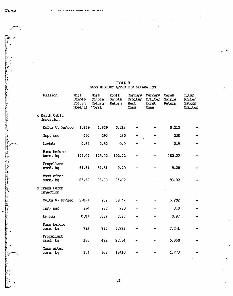
f'\
f1i\~ . .( r'
·rr':. ~ :} . ,
.' . ,
'L'\BI£ 9 ,..~ HISTORY lnER C1I.V SEPARATION
llission Klrs Mars F.opff Hercury Hercury Ceres Titan Sitt1ple S • .1:r:ple Sa~1.e Orbiter Orbiter Saor:ple Probel Return Return Return I3cst h:Orst Heturn SJ.turn Ncxninal Wor'st case cane Orbiter
o Earth Orbit Insertion
Dcl ta V, krnI sec 1.929 1.929 0.213 0.213
Isp, sec 290 290 230 230
La:rhdl 0.82 0.82 0.9 0.9
Hass before burn, kg 125.02 125.02 102.22 102.22
Propellunt used, kg 61.51 61.51 9.20 9.20
Mass after burn, kg 63.50 63.50 93.02 93.02
o Tr.:ms-E.lrth Injection
Delta V, kmlsec 2.027 2.2 3.047 5.292
Isp, sec 290 290 298 310
Iil:rtxil 0.87 0.87 0.85 0.97
Mass before burn, kg 722 7BS 3,993 7,241
Propellant used, kg 368 422 2,584 5,968
Hass after burn, kg 354 362 1,410 1,273
53
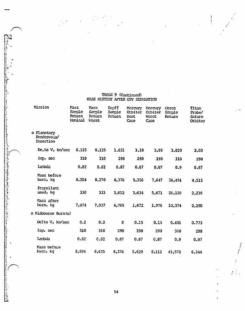
TlIBIE 9 <Continued) M.!\ss HlSIORY /\FTER (]IV SEI'Ar-ATION
H.i!>sion Klrs Ham Kopff P.ercury Hercury CerC5 Titan S<rr:ple &.."'"T'pl. e s.:.rrple Orbiter Orbiter ~e Probe! Return Return Return Best WorGt Return Saturn tminal Horst Colse cane Orbiter
o Planetary Rendezvous! Insertion
De ... ta V, krrl sec 0.125 0.125 1.651 3.38 3.96 3.029 2.00
Isp, sec 310 310 29B 29B 29B 310 298
l.il:Wda 0.62 0.82 0.87 0.87 0.87 0.9 0.87
Mass before burn, kg 8,204 8,270 B,376 5,306 7,647 35,494 4,515
Propellant used, kg 330 333 3,612 3,634 5,671 26,120 2,236
l-'.ass after burn, kg 7,874 7,937 4,765 1,672 1,976 10,374 2,280
o Midcourse Burn(s)
Del ta V, krnI sec 0.2 0.2 0 0.15 0.15 0.481 0.773
Isp, sec 310 310 298 298 298 310 298
L<m:xia 0.82 0.82 0.B7 0.B7 0.B7 0.9 0.87 I
,,:ass before I burn, kg 8,894 9,635 8,376 5,629 8,112 43,570 6,344 I ,
~ . ~~, f:. ( , .
54

(\
~ ']
1
J :1 -. TlIBIE 10 d . '-'I
SIN:iLE STl..GE (J'N's ~
'-. i f-tission M.lr5 !-lars Kopff Hercury l'~ercury Ceres Titan
Sa:iiple Sa:r.plc 5...-vrple Orbiter Orbiter &-""rlp1c Probel P.cturn Return Return Best Wornt Return Saturn fbninal h"orst casc ca~ Orbitcr
T o r..m DeparturC', 42 metric ton rrax propellant single stage OTV with acrobrw(e
J "'Any of the5C st..lges sh(1Wing morc thm 42,000 kg o! propellant will require il 2nd stilge and the nur.ix>rs here should be disregarded
·.-1
<! Delta V, knv'sec 3.59 3.63 6.41 4.01 4.38 3.63 5.30 !I --'1 ~inite burn
j 105s, kr.'/zec 0.1 0.1 1.4 0.06 0.07 0.35 1.4 -.
-.--~ 'l'.>t. Delta V, :, knVsec 3.69 3.73 7.B1 4.07 4.45 3.9B 6.70 i r'j f ~ P.cturn Del ta V,
i \t.':Vsec 1.45 1.50 6.19 1.89 2.32 1.78 4.91
L 0 Isp, r,cc 455.4 455.4 455.4 455.4 455.4 455.4 455.4 ~ ~
Klss ilt return burn, kg 9,712 9,823 2B,045 10,715 I1,B03 10,459 21,070
--
~'1 P.eturn Prop., ::1 kg 2,684 2,795 21,017 3,687 4,775 3,431 14,042
1 O-!ttcund Pass before
--:;1 burn, kg 44,031 46,466 214,204 41,619 55,116 133,702 125,755 >) -0
-" Propellant * * * .:}~ ;g "I
used, kg 24,398 25,941 173,304 24,512 34,195 77,634 95,799
-" ,.lass after ,.~~
fe- burn, kg 19,634 20,524 40,900 17,107 20,921 56,06B 29,956 ~.
r ;7i o LEO Departure, 42 metric ton max propellant single stage OTV, no aerobr ake }1 no return, delta Vs and other par~ters the ~ as rcturned vehicles .;;' . ~ .. Inert mv rrass, ':1 ~ '~l kg 5,243 5,243 5,243 5,243 5,243 5,243 5,243 , '5~ . . ~' ~ a OJtbound :j~, .it I·ass before t!~, burn, kg 33,687 35,757 80,636 27,811 37,0% 120,818 53,541 :~',; 1 Propellant }'i "~I used, kg 18,666 19,963 65,240 16,380 23,016 70,153 40,787 ;'j .1"
"I l-ttss i fter
'.j. burn, kg:ns 15,021 15,794 15,397 11,432 14,OB1 50,665 ] 2,754 ,
" :,', 55

:~ :;::
not ret.urn. More calculation has :"..50 sho .... n that this Titan mission can be flown .... ith a 42 metric ton OTV .... ith the aerobrake on, if no OTV return is required.
The Kopff and Ceres mi~sion9 still require too much propellant and must either use additional propellant tanks, with total capacity in the 70 metric ton range, on a oingle stage or a second stage. Table 11 shows the mass breakdown for the two stage LEO launch of the Kopff and Ceres missions. Both OTV otages retain their aerobrar.es, but only the first stage returns. Return of the second stages requires over 42 metric ton~ of propellant in each ca~e. OTV's at or ncar the end of their useful life could be used for the second stages on these missions and for the single stage of the Titan mission.
Tablp. 12 shows t.he mass breakdown for a single-st.:lge expendable ftrubber R OTV. These OTV's, though not really options, give an idea of the mass of a design optimized for a Single given mission. A small kick stage woul d probably be used to further reduce launch mass on the Kopff and Ceres missions.
Table 13 summarizes the Earth launch requirements for each mission in terms of Shuttle and ULV loads required. The hard .... are required for each mission, except for the Ceres sample return, is in the range of 20 to 40 % of a shuttle load to the Space Station orbit. The number of Shuttles requir€d to carry hardware only, and propellant only, and the number of ULV's required to carry propelldnt only are all tabulated. Figure 15 is a bar chart of the Earth launch requirements for payloads and propellants. This is shown for shuttle only missions because the number of missions required to support planetary flights do not justify the develop:nent of ULV. It is likely however, that if the OTV infrastruct'Jre postulated exists, a ULV to fuel the OTV will also exist, paid for by some program other than the planetary.
Table 14 shows all the constants used to size the planetary mission OTV's. These come from reference 2 and Eagle Engineering estimates.
56

;~~ ,.
~:. i ..
" 7:~ .i..~
.r.~ ... r ~ . ;'-
TABU:; 11 'Th'O STl\GE arv's
~lission Hars Hars Kopff Mercury 5.:::nple Sample S.1:nple Orbiter Feturn Ret~rn Return Best fJcminal Worst case
o rID Departure, two Gtage (]IV,
each with 42,000 kg prop. ~1pacity and an aerobrake. Only the 1st stage returns.
2nd Stage Del ta V, kr:v'sec nfa nla 6.17 nla
Isp, sec 455.4
Tanks,& engines, kg 5,243
Mass before burn, kg 55,739
Propellant used, kg 40,950
f/ass after burn, kg 14,789
l.nt Stage Delta V, kmlsec 1.64
Feturn Delta V, lor/sec 0.365
Isp, sec 455.4
f1ass at return burn, kg 7,626
Return prop., kg 598
t-lass before wrn, k.g 92,489
Propellant used, kg 28,218
"'.ass after burn, kg 64,270
Total (]IV Prop. loaded, 1st & 2nd stages, kg 71,510
57
\ \ ,
fIlcrcury Orbiter \iorst Case
nla
Ceres Titan Sample Probed Return Saturn
Orbiter
2.72 nla
455.4
5,243
90,885
40,950
49,935
1.26
0.365
455.4
7,626
598
131,591
32,079
99,512
75,467
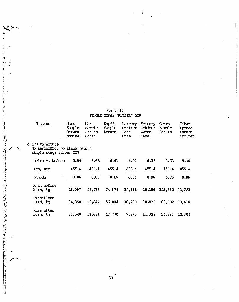
'.-
:;. ..
TABlE 12 Snl;LE ST/i;E "RUBBER" (JlV
Mission Mars Hars Y.opff ttercury l~rcury Ceres Titan &.--r.p1e &..'""'l':p1e Sa:np1e Orbit:er Orbiter &ll1ple Probel Return Return Return i32st Horst Return Saturn Ncminal Worst case case Orbiter
o LID IRparture N':> aerobra:<e, no stage return single stage rubber aIV
Delta V, kmlsec 3.59 3.63 6.41 4.01 4.38 3.63 5.30
Isp, sec 455.4 455.4 455.4 455.4 455.4 455.4 455.4
La:rbda 0.86 0.86 0.86 0.86 0.86 0.86 0.86
Bass before burn, kg 25,997 28,473 74,574 18,568 30,156 123,438 33,722
Propellant used, kg 14,350 15,842 56,804 10,998 18,829 68,602 23,418
Mass ilf te r burn, kg 11,648 12,631 17,770 7,570 11,328 54,836 10,304
58

J j f"\
t J
I '1 i '. ~ T1\BLE 13
L\l.Jl'Ol RmUIRU!EN'fS
Hission MatS Mars Kapff r-'.ercuty r-'ercury Ceres Titan Sample S<m:ple Sample Orbiter Orbiter Sc1mple Probel Return Return Return Best Worst Return Saturn Naninal \'jorst case case Oebiter
o S~ of Launch Requirancnts, from the surface
Shuttle only scenario
Shuttle capacity, less }\SE, kg 25,000 25,000 25,000 25,000 25,000 25,000 25,000
(55,000 1bs) * Total hardware to
be 1aunched,kg 9,312 10,052 8,523 5,779 8,262 43,668 6,492
lb. of Shuttles req. for hardware 0.37 0.40 0.34 0.23 0.33 1.75 (:.26
Total IfJ2IH2 to be launched,kg 27,759 29,455 71,510 28,904 39,945 75,467 41,807
Reusah1e Rausab1e 2 Stage Reusable Reusable 2 Stage lbo-reuse. 1 stage 1 stase 1 stage 1 stage 1 stage
Tankage for ID2IH2, kg 1,262 1,339 3,250 1,314 1,815 3,430 1,900
lb. of Shuttles req. for IJ:J2/H2 1.16 1.23 2.99 1.21 1.67 3.16 1.75
Total No. of Shuttles req. 1.53 1.63 3.33 1.44 2.00 4.90 2.01
Shuttle Derived Vehicle WrN> Available to carry UlXIH2
Capacity of ULV, kg 113,636 113,636 113,636 113,636 11J,636 113,636 113,636
(250,000 1bs) l'li. of ULV's req. for L02IH2 0.24 0.26 0.63 0.25 0.35 0.6f 0.37
* This includes all propellants for the planetary sp:lcecraft and launch adapters. It does nat include the CfNs which are assu:red to be space based.
59

TABLE 14 VJV can'STNlTS
Hission Hars Mars Kopff Mercury Mercury Ceres Tita., &Jmp1e San:p1e Sa:nple Orbiter Orbiter sample ProteI Return Return Return Best Worse Return Saturn Naninal Norst Case Case Orbiter
~ o OTV Constraints, Total dry rrass = A + B* (Propellant ~';eight) . ~. A = AI. + /12, B= Bl + 132 + B3 + 84 ~: ~ . Al, Dasic, kg 2,284 2,2B4 2,284 2,284 2,284 2,284 2,284 t ,-~, /12, Aerobr ake, '" '1 kg 1,447 1,447 1,447 1,447 1,447 1,447 1,447 .\ .,.
't ., A, Total, kg 3,731 3,731 3,731 3,731 3,731 3,731 3,731 of
~' :!- BI, Basic 0.04545 0.04545 0.04545 0.04545 0.04545 0.04545 0.04545 .~ ., .1 ~ 132, Aerobrake 0.00B05 0.00B05 0.00B05 0.00B05 0.00B05 0.00B05 0.00B05 ;~ .:,. ~:; 83, Residuals 0.01 0.01 0.01 0.01 C.Ol 0.01 0.01 " -'. 84, Hixture ratio & ", Isp vari ation 0.015 0.015 0.015 0.015 0.015 0.015 0.015 :/. I .....
;-8, Total 0.0785 0.0785 0.0785 0.0785 0.0785 0.0785 0.0785 ;~
~ .- r-lax alla-rab1e ~.
propellant, kg 42,000 42,000 42,000 42,000 42,000 42,000 42,000 ;. , .. '.-
,'i~ ,
'i . ' . . "
.,<
f' ' . . , -~ ;
::;: 60 I') ; i ~:
[.-

\ ., tlZOI-w\t.aO:....,.,.'-·;..A ....... $.>.....:3 )='" . . .
.'T"\'I :;'j,;e .", .• f,if\!,~ F, '-OJ i •.. ,#.",3,'1 •. ;q~ .-..... ':.",", -S·".,}: :'[ ,.":', '.-: . .c<'7?,~~ \ .... "'"""._'. ·a~ . ..,Oo6"'''''''''''''_,i,. - ... ,; .. ,_J.'-".\':~"'._""'''~.~~~~~''r.:-J~ """ ...... ,~ ... I.~.
/::;::;"'T":;,~.-:.)Ji""."'''!'-:';:::''',·~~4.f·\''·~. 1;.~." ... ,::b"'::hJ~·~~:':S1J
".-.. .... ~
c: 1.0 N .......... .0 ..::.: :.") 1.0 ......., (f)
C .. c.: ....J
W .....: l= ::> I if,
C. ..J
4
3 -
2
S rl UTTLE f'y'l iSSIOi\JS REQU IR ED FOR P~.NET.1RY '"ISSIONS
1 -V'//"/"j Y /"./ /" J V././ /" J v./././ j V././ /" J V././ ...... 1 V/"'/ /"1
o MSR r~om r.~SR Wor5l Kopff SR MO Best MO Worst Ceres SR TP ISO
PLANETARY MISSION tZZJ L02/LH2 for OT\/ cs:sJ PAYLOAD
)'i.", ",
.
~~lojr.,J1,.N·~ __ t
V
-- )
\
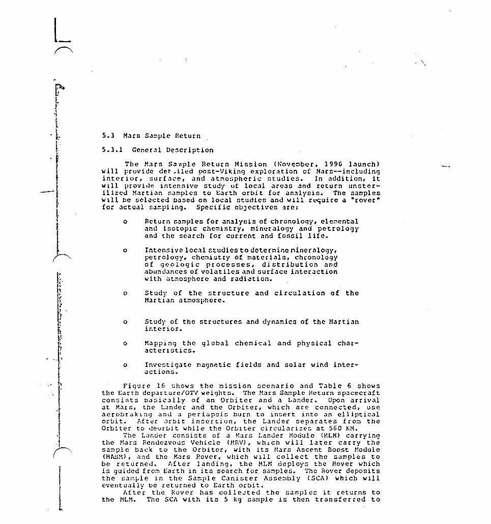
~' .
1
L f
-1 E
o~
t
l
5.3 H~ro Saoplc Return
5.3.1 Gcncr31 D~5cription
The t-~.Hn S.,'lIplc Rcturn Minnion (t,o'/c::lber, 1996 l.lunch) will provide det' .oiled pont-Viking cxplor~tlon of t-t.lrn--includlng intl.'rior, !>urf.'1ce, <lnt! .'lt~or.pheric ntudieo. In addition, it wl11 provide intcnolvc ntudy uf local ~rc.,s ~nd rcturn un~terill%cd H.'1rti.ln samplen to E~rth orbit for an31ynin. Thc B~rnpleG wl11 be ficl~ctcd based on local ntud1cc and will rL~uire a -roverCor actu~l r.3~plinCJ. Spccific o~Jectiveo ~re:
o Return t;ar.lple:; for an.llysin of chronology, elcr.lental and iaotopic che~i5try, mineralogy and petrology and the search for current and (090il life.
o lntcn:;ive local studies to determine niner41ogy, 1-'CtcoI09j', chemistry of rnater i..'11!l, ch(onology of 9t:'ologic proceGses, distribution and .lbu:oldolnces of volatiles and surf.lce interaction with at~osphere .lnd radi~tion.
o Study of the structure and circulation of the Martian atmosphere.
o Study of the structures and dynamics of the Martian ir.terior.
o "tapping the global chel':\ical and physical cha[acterlstics.
o Inve~tigate ~agnetic fields and solar wind interactions.
figure 16 shows the ~ission scenario and Table 6 shows the EiJrth dep.:Hture/OTV weights. 'rhe Mars Sa:nple Return sp.lcecraft consists b.Jsic.Jlly of an Orbiter and a Lander. Upon arrival at Mars, tht:' L;)nder and the Orbiter, which arc: connected, use aerobraklng and a periapsi~ burn to in~ert into an elliptical orbit. Aft~r orbit in~ertion, the Lander separates £ro;':l the Orbiter to Jeurbit while the Orblter circulari~es at 560 KM.
The Lander consists of a ~ars Lander Module (HLH) carryin~ the Mars Rendezvous Vehicle (MRV), whJ.ch vill l.lter carry the sample back to the Orbiter, with its HarD Ascent Boost ~odule (HfillM), and the Mars Rover, which will collect the samples to be returned. lifter landing, the 1-IL"1 deploys the Rover which is guided from Earth in its search for samples. The Rover deposits the 5a~~le in the Sa~ple Canister Assembly (SeA) which will eventually be returned to Earth orbit.
After the Rover has colle~ted the samplen it returns to the MLM. The SeA with its 5 kg sample iG then transferred to
\

T l
~. . '
',. [. "-
I --
the Hnv vith a crnnc-likc ~c~haniun on the MLH. oolid roc~eto on the MRV ~nd MA~M booster arc into Mars orbit. Once the rffiV <lchicvcn orbit Vehicle (HOV) ~AneUVerG to [cnd~ZVOU5 with it.
Th.! Gtcrili;.:cd used for l.lunch tht: Harn Orbiter
The Orbiter, known all tilt.: Molrn Orbit Vehicle (MOV) contnins the E.lrth Return Vehicle (t;RV). The ERV in turn houGen the Earth Orbit C.lpnule (~OC) which orbits E~rth w~itin1 to be picked up for processing at the Space Station.
After the docking in Molrn orbit of the MOV with the MRV, the Sample Canister io placed into the Edrth Orbit Capcule. Thin is its iin.ll position for return Lo the Earth S~ace Station. When thin transecr has been completed, the Earth Return Vehicle, detaches f rom the MHV .:md MOV. The ERV protccta the EOC with the SCt\ during the tr.lns-E.lrth voyaCJe and in jett150ned just before arriv.::l. The EOC firnt in:;erto into Earth orbit, and then carries and protects the SCA and sample while they arc w.li ti ng to be pi cited up by an O'l"V <Orbi t Transfer Vehicle) 0" OMV (Orbit H4neuvering Vehicle). This general description was derived fro~ references 4 and 5.
5.3.2 Spacecraft Mans Estimates
As dencribed previously, th~ Hars S.l~ple Return spacecraft consists of several discrete modules. The weights of these modules are given in Table 15. The sum::lary sep:Hates the sFacecs:aft into thr~e systems: Earth Return Syst~~: L<lnder/ Rendezvous System .lnd Orbite::/Earth Dep3rture S~'stems.
The E<lrth Return System includes the Sample Canister. Earth Orbit Capsule and the Earth ncturn Vehicle. The Lander/Rendezvous Vehicle includc~ the Mars Lander Module and the Hars Rendezvous Vehicle along with the HAEM booster. The Orbiter/Earth Departure Systc:n is the Hars Orbit Vehicle which serves as the Earth Departure System as well.
A separate section is included for miscellaneous adapters vhich includes the departure ~ioshield and the adapter for the Orbital Transfer Vehicle for insertion into trans-Hars orblt fro~ Low Earth Orbit.
This ::tass properties infor::tation was der ived f rom Reference 5.
5.3.3 Delta ViS
The Delta ViS used for the Mars 9ample ret~'n mission also come from reference 5. The baseline trajectory includes an aerocapture into Hars orbit, a perigee raising maneuver, a lander deployment, a circulariz<ltion naneuver, a Mars orbit rendezvous with the fiample carrying ascent stage, trans-Earth injection of the fia~~le and carrier, and propulsive earth orbit insertion into an orbit from which the Spac~ Station can capture the sample with the OHV or OTV. The sample in inserted into a 280 km perigee,

f'\ ,:"\'t' -'- .. t!, .. U Y f fa-tip
C\ .:.
,~f~;, .... -.~,~,'~,.,!.f..' ";,,",,, .. \ P""lr,··.,,~,:.·~~:;:'lr-:r~~'f~.~·,::r~?~iJ:-""~l~:J~-;J~~~~~~~~;.;~ ·)'.:'"':L.:i:~:~.f:- : .. :j;: .. 2f~;·-:' ,( ..• ,-., "r,-. ,.:.. ),i:.. .. i;~:- .,.,t"":..-~!l"'H,;;r~;.;';';;:]
r·l;'\RS S,\t.\PLE RE TURI. SC£lMR I 0
1. STACK lEAVES SP/,CE STATIOU
2. TRMS-j,1.AHS I UJECT IOU
3. FIRST STAGE RETURNS
1+. T'UUlS-r~,\RS VOYf,Gf.
5. AERCCAP TURE Mi:J /·1:'f{S OHU I T I NSERT IOU
6. JETT I sor~ r/,ov AHWSH(Ll
7. LI\I,OER AND ORB I TER SEPAR/~TE
8. LJ\NDEP. EtHERS r"ARS 1\ T/·WSPHERE
9. LANDING ON MARTIAN SURFACE
10. COllEe. SJ\!·lPlES
11 • LAurlCH F RO~-1 MARS
12. r,ll\RS RErmEZVOUS VEHICLE INJECTION nHO r·1.\RS ORBIT
13. r·tt'l.RS ORB ITER VEH I CLE 'ltAr.UEVERS TO RErmEZVOUS \-11 TH ,·':.:vJ
14. TRANS-EARTH INJECT ION
15. TRANS-EARTH VOYAGE
16. EARTH ORBIT CJ\PSUlE INSERTION INTO EARTH ORBIT
17 • OVN REfiDZVOUS vII TH EOC
18. or,w RETURNS EOC WITH SN·\PlE TO SPACE STATIOU QUAR,\fHINE t'~ODULE
FIGURE 16 LEGEfm
) I$~Q
I

OF POOR Q~ALn'
Figure 16
~I Ii' . I
.... - ..
.'
c ... :J -Cl 0:
-. "
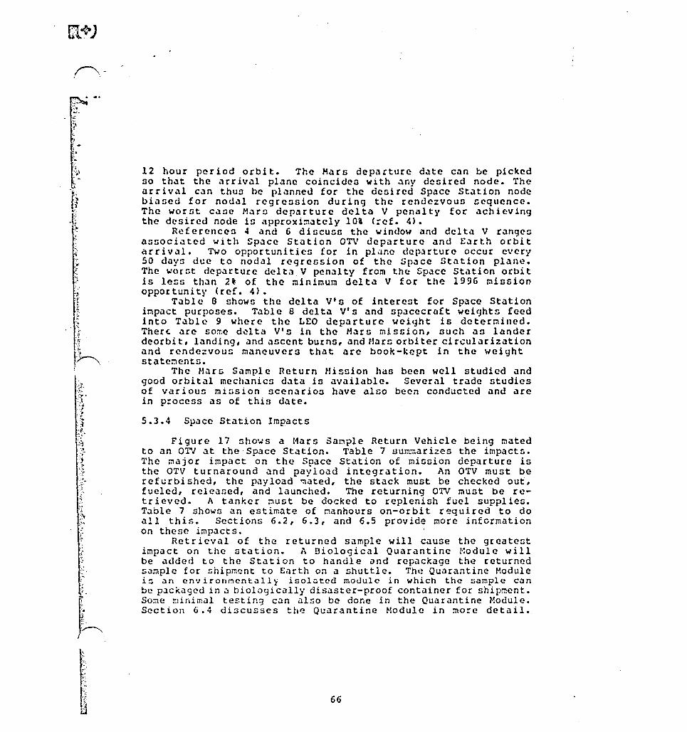
('\-
.. 1
" :"t
;-'.
12 hour period orbit. The Mara departure d~te can be picked so tholt the arrivoll plane coincides wlth .lny desired node. The arrival can thu~ be planned for the defiired Space Station node biased for nodal regression during the rendezvoua Gcquence. The worst cane Marc dep.:trture delta V penalty for achieving the desired node in approxi~ately 10\ (:ef. 4).
References 4 and 6 discuss the window and delta V rangen llnGociated with Space Station OTV departure and Earth orbit arrivol!. Two opportunities for in pl.1nc dep,Hture occur every 50 day5 due to nodal regression of the Space Station plane. The worGt departUre delta V penalty from the Space Station orbit is less than 2~ of the minimum delta V for the 1996 mission opportunity (ref. 4) •
Table a shown the delta V'o of interest for Space Station impact purposes. Table 8 delta V's and spacecraft weights feed into Table 9 where the LEO departure weight is determined. Ther~ arc so~e d~lta V's in the Marn mission, ouch an lander deorbit, Itmding, and <Incent burns, and Hars orbiter circularization and rendezvous maneuvers that arc book-kept in the weight statements.
The Hars Sample Return Mission hdG been well studied and good orbital mechanics data is available. Several trade studies of various miGsion scenarios have alno been conducted and are in p:occss as of this date.
5.3.4 Space Station Impacts
Figure 17 shows a Hars Sample Return Vehicle being mated to an OTV at the Space Station. Table 7 su~~arizes the impacts. 'l'he major impact on the Space Station of mission departure is the OTV turnaround and payload integration. An OTV must be refurbished, the p<lyload 'l1ated, the stack must be checked out, fueled, released, and launched. The returning OTV must be retr ieved. A tanker must be docked to replenish fuel supplies. T~ble 7 shows an estimate of manhours on-orbit r~quired to do all this. Sections 6.2, 6.3, and 6.5 provide more infcrmation on these imp<lcts.
Retrieval of the returned s<lmple will cause the greatest impact on ~he station. A Biological Quarantine Module will be added to the Station to handle and rep<lCK<lge the returned sample for shipment to Earth on a shuttle. The Quarantine Module i~ an anvironnantall~ isolutcd module in which the sample can be packaged in a biologically disaster-proof container for shipment. Some minimal testin~ c~n also be done in the Quarantine Module. Section 6.4 discusses the Quarantine Hodule in mocc detail.
66

'" J'.
THIS Pl\GE IIITEHTIOUl\.LLY
LEPT DIJU-m
67
I

- ...........
f"\ .
, v,:'
~ :$.i ~ .
.,1, ,.1.,
)J ~ ,'41
:th
, .
r,L\RS SN·\PLE RETURH SPACECRAFT - OTV t'lATING
1.
2.
3.
4.
S.
/' .. 0 TV
;.1ARS S/J.\PLE RETURfl SPACECRAFT (I NS I DE AEROSHELU
OTV t-::'I!IGAR
osr,1 (PROPELU\fn STORAGE r·mOULES)
FIGURE 17 LEGUm
:

·',J.,
\h .. :\ .,';1 , f :,".
!i
~;J' .'J "~" . . 'i;~ .. :'~
.~-!."> I
',~::i "
-I.
, < :.. ":' ~ " -
l-I
0.'\::'" ' .. , ''" ~ _ .... ,j II ,t,_ (~.:.. "-_ •... ~:,
OF POOR Qi';,,\UTY - ~ .-: ,"'"
, ... ~ .. :
./ .
/
I
Figure 17
69

-j-
-:.? -::; . t. ., ii' ~ "~ ,.'!t.
.. ~~ . ", ;, -~.:;: Y'-"\ ,
-)0,
.~ '. :~ ~,
2. :T ':f--i; •
{~ ~t ::
TABLE: 15 Mus Sa:rple Return Miesion Weight Statement
Daacription Item (kg) Totals (kg)
EM'll1 RE'l.URN SYST"'cl'S SNiPLE CANISTI::R ASSmlLY
SCA 15.0 SJ\."fi'LE 5.0
'I:r:1rJIL SCA 20.0
EAA'lH amIT G\PSULE <n<l!'iJ?l'I CATlrns 1.6 RliER ASSO"l3LY 3.B 'lHERHAL (XNffiOL 3.0 SRH IGNITER J\SSflIiBLY 0.3 GAAPPLIl'G & REaJllXl 1.2 SCA tON rroR 'lU
OllI'ACI' ASSEl'aLY 1.4 BUS smucruru=; 10.2 CXJlER J\SSEriaLY 2.4 HEQiJ\,'USHS (MISC.) 0.7 RETEl-1I'ICN PillS 0.6
SUB'I'OTi\L 25.2 CXlll'Il'GllO 4.8 VEli. 'IOTlIL {DRY} 30.0
+SCA 20.0 'lOTAL 50.0
EAA'lH OR3IT lliSmI'ICN PH)P.: SR-! ffiOPELLANT (3 S:;:'S) 61.5 290 Isp SRH STruCIURE D.5
'roT1\L EOC 125.0
70

TABlE 15 "'ars Sa:rple Return l-tission Weight Stat~ent (Continued)
==::z:.=-===========r==== Description Item (kg) TOtals (kg)
==
c::::=======rr:==r-- -~=====-=-""'====="'=-':::-==-=-'-=-=n=:r:=T==r:=-=:;--===:a:=.c:::::;.::
EM'll1 REIU~ VEHICLE TU.EClJM 19.5 ro ..... rn 20.4 ax~ll ... ~ & Ot\TJ\ (WIDLIt!; 14.0 lUTrruDE & ron-trnl; Cl'RL 13.7 roc UITC}!lUNLATCH 2.9 roc SEP SPRn,x:;s 1.0 SR.\1 SAFE/ P.ru1 OOX 2.2 PYRO UNITS (2) & SQUIBS 1.9 BUS /\'~1) 9..lProRT 27.0
SIRUCl'URE IDU> cnmoL 8.9 C/ill w,x:; 11.0
SillTCTJ\L 121.3 ro~ENCY 11.2
'lUI' At. (LRi) 132.5 RCS: WOOS 10.0
9..lPFffiTS 1.2 PROl'ELI..N 11' U!2N4) 30.6
VElI I Cl..E 'IOl'AL 174.3 TOTAL rnCL UN+illC 299.3
'IRJ\NS F.AR'IH lllSERI'Irn ProP.: SR."l PROP 367.6 290 Isp SRM STFUClURES 54.9
'lOTAL rnCL. rnIJ+'I'EI FROP 596.9
'IDTJ\L F.J\RnJ RElUrn S'iS'IEM 721.8 (ERV+'I'EI rnDP+mc)
71
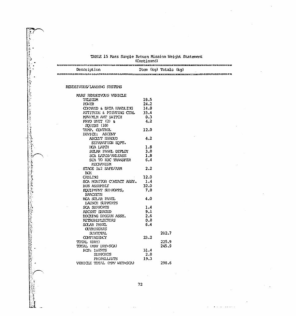
W·,· "f", .
.. :~~'- -'.;:
:.~ .
X .... ·-.14 • :1 " "'"J"
!..-
f . .
; .. :c. .~.
TJ'\DLE 15 Mus Sa:nple Return Mission Weight Statement (Continued)
===-====:.::r::;...:;~===:.z:~~,,=:==.,.===============.=...-:=::===
Description Item (kg) Totals (kg)
IIDIDEZ\WSlU.rIDIN:J SYSIDtS
l"JI.RS lmIDEZVOOS VEllla..E TEl£a::t1 18.5 ro ... rn 24.2 m::-v ... "ID £. [}\T/\ m\;\'DLuJ:; 14.0 l\Tl'I'l'UDE & ronrrut; crru. 33.4 MIN/WI 1 ... \.T S';ITCH 0.3 FRYO UUIT (2) & 4.2
rollInS (30) TE.'1P. CD.\rrn.a. 12.0 DC.VIa:: ASffi'f
ASru.'T smUJD 4.2 SEP1'\..~ICN mPI'.
lGA U\l'01 1.8 SCLAH PNJfL DEP"~ 3.0 SCA Lt\'lUV RU.EASE 1.8 sa 'IO me ~FER 6.4 ~fr..UIN'HSM
Srt"{;E 1&2 &\FE/A.ttl.! 2.2 00<
C\BLI~Ki 12.0 SCA r-nnro1 c:rm\cr ASSY. 1.4 BUS ASSmBLY 32.0 muIPHP.'tr SJl'roRTS, 7.0
8Rt\Q\E'1S lGA sa.AR PANEL 4.0
LAL'Nffi suproR'I'S seA SJ?ffiR'IS 1.4 ASClliT ~lP.ClJD 9.1 rxx.~nx; DRa;UE 1SS'l. 2.6 RE'ffiOREFLECIDRS 0.8 saJ\R. PN~EL 6.4 a.rrn.m:;EFS
SJB'IOTAL 202.7 aNrU,GENCY 23.2
'TOTAL (DRY) 225.9 TJrJ\L (MR\T DRY+SCA) 245.9
RCS: WERTS 31.4 SUPIv.'1TS 2.0 PROPELU ... \"!S 19.3
VflUQl; 'IDl'AL (MRV Wl:."l'+SCJ\) 298.6
72

T!~LE 15 l-Ur~ S<.:mple P.eturn ttission Height Statanent (Continued)
=c=====ca======.=============~~=====================~~=================~c===~
c= Description
:-~=-==================
ST1£iE 2 PROPl.[.S I CN: S~' PROPEl.J..N':T srut BUR..aJr HASS SRM SUProRT
'lUrA!. ST/;GE 2 VClIIC!.E 'TOTAL
(HRV+SCA+ffiOP STlGE 2)
S'TJ"{;E 1 nm:RST1GE ADFl'R SEPAAATICN DEVICES CJ\BLn~
PROPl.[.S I CN: SRM FROPELI.r>,NT SRM BUF:.Joor 11ASS SRM stirroRT
'IOTAL STi'..GE 1 ClJMULl\TIVE h'EIGHI'
Iron (kg) Totaln (kg) =================================-~-
228.5 31.5 7.3
30.2 4.0 2.0
1142.7 138.8 32.0
267.3 565.9
1349.8 1915.7
280 Isp
280 Isp
(MRV + SCA + Sl'AGE 2 + srl(;E 1)
HAAS ASCElrr BOOST I-OIlJLE SJPRRT TRlSS SAFE/ARH BOX SEPAAATICN DEVICES MLM RELFASE HEQI CABLU-l; IIFAT+ PLUME: SH IELI:6
'lUrAL (D.~)
PROFULSlOO : Sre1 ffiOPEI..LrlNl'S SRM ~rur MASS SRM SUProRIS
OJmUaIVE 'IDTlIL WEIGln' (MRV + SCA + srliiE 1 + SI'liiE 2 + l-Nl.' .. n
58.4 2.2 9.0 2.8 3.6 8.5
515.4 76.8 17 .7
73
84.5
694.4
2610.1
280 Isp
",'
"" \ "
( I'
.. :
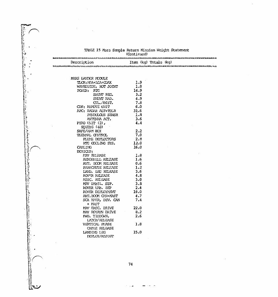
~
!:r!, ("'\ [\ '
I\~ t· j' o
f~ .. ~ t·P
•
\~.~ . ... ~ , .. . ~
'. '. '"
-;,; .
TABLE 15 Ham Sample Return Hission Weight Statement (Continued)
===-=---- -- =========== Descri~ion
-::-====--:::. -
MARS IA'IDER r-oOOLE 'ILG1: fC.A+ IGA+ID\x WAVEriUIDE, lUI' JOINT pa·;m: R'lC
SHUln' R.U:;.
SHUNT R.'\D. CI'L./DIST.
CIlI: RElVI'E UNIT ~: RJ\n<\R AL~'IDLR
PrnDULOJS SfliSR A. ... nU.lJ,\ Acr.
PYRO UNrr (2), 9;2UmS (~O)
SAFE/ARM OOX n:Em·W,. aWIRor..
PLtr.!£ DEfLECTORS R'IG <X'CLll.;c SYS.
CN3Ln~ DEVICLS:
~'JN RELEl\$E AEROSiELL RELEASE NIT. rro1 RU.fASE Pl\lU\Onn'E RELF.IISE IA\U. LEt; RELEASE ROJ~ R1:l.EASE msc. RI'LEi\SE MRIJ UmIL. SEP. ROJER 1..,'1''3. SEP ROJER DEPLOYl-1lliT l'Nf. BXl1 O\N+f>'AST SCA XFER, m .. v. CAN
+ W..sT HRI rnEC. DRIVE NRV lUl'ATN DRIVE FWD. TIECOlN,
LA..rnoll RELEASE VERTICAL HlASE
CAEI..E RELEASE IA\1J)Il{; Lill
DEPLOY/AIlJ usr
Item (kg) Totals (kg)
74
1.9 1.8
14.9 3.2 4.9 7.B 6.0
31.6 l.B 3.6 4.4
2.2 7.0 2.8
12.0 16.0
1.8 1.6 0.6 1.2 3.6 4.8 3.0 3.8 2.4
18.0 4.7 7.4
22.0 8.2 2.6
1.8
15.0
===

- • t"
, ,
,I
r'guru 1:)
61
' ..
TNU.£ 15 KU5 5.l."'iUC f~turn P-ir-...:lion Wci(jht St.lt~t (Cont1na::'d)
ro~l.~: S(%J\..q r'i'~m..s wmt
sm ... "'lF.!\'n: B.\1TC.:>tU:S BA1Ti-m' Otr'UGER <n>!)lTIWI~t.; mrs.a. DlSlHllmlaJ
17.0
25.2 3.4 7.6 3.8
;"TrrR'Dr: 'lU roL'r.I!G s--:~ S!2Sm (2)
~: ... q S[~~lJH (2) IP.u (2) ACO: l.!::R':l'::"'"!"f..'q
mma.: 1.0 5.4 6.4 0.7
ACCU.u·:J~£.·r~ !ucr ~,";:n~~:.A f,(,:W;UORS (2)
NIT. <..-:1.. lU:cn-.-:K:S ~·~\!~r;,T!, ii.Nal~J:S:
C!ll ~~:; r:. L~~IT (2) n\Tt\ ~;'!'C?i':;:; (2)
T/ a ... v.:l\t\ Wlt1.Ec:lFClaCS n:~.J'?f~1\.j HE (t.\'."IR(L:
U~S~ ... '\TICti LU.·/i?.S H:::AT'::::~
P'l'RO v:aTC2J, XUlBS!20) H.f!J)U'JClJS+ l.lX:K m:; G,a m:.
FIJrT. SPI~~ '1J\BI..E W.rRIVE P.:..U!l.:ac,\L r~:.'1a:s:
S:Li ... '{ f,-'::El. [£i1_~. sa.l_~ rt:-n:t. ... lG\
r~\:·:;~.:.HS
i~\ B:..l:=>~ L;~"C'rV H:l..i:.>\SE
'1'.' G~l:~.l\ llo....'V!i UID:HI Iill.lJ .. SE
m.: P3'll.5ElSEP,\R. B!C6!1a:I.o hELF:.r.sr; [tU L:!-'IH L. ru..--:W\Cf fR: P.:,.::: .... 'iE/s!.:? [IXKl!~ CU;£ f<ILE1SE
G-"!3U}{'
2.3 3.6 3.2
11.6 2.4 3.0
7.6 6.8 1.8 ';.0
12.0
10.4
4.2 3.4
2.2
1.0
4.2 3.3 1.2 4.2 2.0
Hi .0

TNH.!: 15 !"aUll &!::?lc r~turn H.i~ion Weight St.'ltc.r.t!nt (Contint..'t.~j)
{)~:;Crli'ti(Q ItC1:l (kg) Tot.llr. (le'l) ali;'Z.~~-DEt':"'."'~':'--iJ~~~~a-.';; ... "*,-Dl:Qr=c..:::r.un~~O..Jl,.~$1a:L".~Jt. ... -:ai:'~~u....;;;~_MU~mr2il'8f:8~".-;!!!.DG..I:'lS~
s!K'l"l';:·:~!; : t~:r!:~:.;\ ;:';PIUfi'S i~i-T ~i'rs+ I'.P .... '.QJ:r5 IrJ. i\..U'i '"N C.· ... ~:PA [I..(Ui
SCL ... .R i'i·:;[L o. !":mCX;!jS
oc.oa:c u: i!: iii SPTS
~·i·K·~·~ RW:; ijJt.' ~t;:-iCj~ J~J)
GJlD~'" Bt:...<i :-:oc l.B!~ I: Ul) SJ?rS
mu·J. !t)! (C~Y) !-o/ iJ:·:.:;,;.m~.L F:{O:t:l~~ll'!l wro/}-~~!):
511!.;C':'.:I.E ,".::J &:i:W;<IS
f:-.'CH:l.!.··: .. r .... ID! Pr-D?:: :J"':;1'-~! PFc:~:u ... wr-a'Err QHC. 5urn::rr .. ..r.. P;-.... :)P!:1ll.:ns
a.:~';..1.;\J''''!E J:":JJ.i~
(t.!.!. SYST~'GJ
BI0s:mw
5.2 13.6 3.6 2.4 4.8
9.S 3.6
16.4
58.0 104.6
44.3
617.2
176.6
565.5 330.0 116.9
146.7
271.2
453.9
498.2
1012.5
2304.5
8893.7
9040.4
9311.6
310 Isp 310 Isp 310 Isp
2.5% CF Lh!~n~ VUira.E P .. \SS
3.0~a;- nUD:."TED I'J\ss

~ ~
.;>'
. '
.. /
5.4 Co~ct Kopf! Nucleun S~mple Return
5.4.1 General OCDcription
The Comet Kopff Nucl~~s Sample return ncheduled for launch in July, 2003, wl11 be a follow-on to previous comet flyby and rende:voun rnl$sionG. The return of .l comet nucleun !lample will enable detailed ntudicn of what arc probably the mont chemically primitive bodien in the solnr syntem. The mission will utilize information from the previouu mincionn for preliminary Ga~ple site selection and S~~plcr con:iguration selection.
ThQ specific obJectives of this mission arc similar to tho3e of a comet rendezvoun mission with one notable exception:
o
o
o
o
o
o
Return of narnpleG for analysiG of molecular and elenental abundances, concentration~ of vater and carbon dioxide icen, physical state of aurface material, local inhomogeneity, and critical i!lotopic ratioG.
Produce high level topographic map of nucleus.
Characterize change in nucleus, coma and t.1il through perihelion pdusaye from both the nucleus surface and from orbit around the nucleus.
Study in detail the size, mass, shape, and rotation of the nucleus.
Study in detail the hydrodynamics of gas and dust flow.
Study in detail chemical kinetics of parent and daughter molecules in the coma •
o Study in detail the solar wind interactions.
To acco~plish many of the detailed characterizations, a long duration Lander will be rc~uired in addition to the Samplers. Two Sa:r.plers .... ill be used, one .... ith a Land·:!r. which will stay on the nucleus and one .... ithout .3 Lander. The configuration for the icc surface shown in reference 8 is the heaviest and will be used as a basellne.
Figure 18 illustrates the scenario fo: both the Kopff and Ceres Sample Return Missions. A stack of two 42 metric ton propellant capacity OTV's departs the Space Station. Table 6 surr~"!iarizes the mass breakdo .... n and Table 11 provides detail. The second ~tage does not return and its aerobrake is re~oved prior to launch.

~.~-""-",,.,..., .... ~,:~~ ~."; .... ~\"'.:'!'I''''.'''''''''''It·''!.!'I'.l'''. -.",.,~, .",:.:,!j,~ .. ",~.",,",:,:! :".:,;:,7'~:!:-~~~J-;.J::':'~"",,7 .. . !"'~ ..... '~~7;:;-... 'j'-~1i-:;,:,~:-:,,7:"; ...... ';;';":i '':'~~-.;':.i'~''~:· ·;:~:':;irt;::·,<0'j. -) , .. , ...~ ..... .",,:, .. ~,.:{'; ., .. ,;:,' •• t .. "J ........ ,/~ ...... ,,,, ".£":,,-:;: ,',' .. ;k "<~~~!"I".o'r£~~
C[RE.S OR KOPrF SM.~PLE I'~L TUf~:1 SC:EtJ.iRIO
1. ST/'.O~ DI:.I'MHS SPMl S r /~ r 10:i
2. FIRSl Sl/,GE OLJRU, SEP/H~."'T1orj t.~.u RETURU 10 SPACE STATIO:.
3. SECO:_D ST:~GE OURr~, 1;V\j~5-C£RtS/KoPFr VO'U' .. G£
1+. SP,'\CECR~iFT RErmEZVCuS MlO A~TEROIl)/C01lET SURVEY
5. LArmER ON SURFACE, SPACECRi~FT Hi ORBIT
6. SPACECR'~FT R[COVER5 sr.~.:PLfRS flrlO DEPt,RTS FOR Et.iHH
7. TRAliS-EARTH VOY,'\GE
8. CARt< I ER MOO L~RTH QiW I T Cr.?SULE SEPt~R,\TE :;. EOC AEROCAPTURE FOR Er.RTH uRB I T II.SERT I au
~o. CIRCULARIZATICN ABOVE SPACE STATIO~ ORBIT
11. (J..1V RErwEzVOUs ~/ITH EOC AriD RETURN TO SPiKE STATION QUARATINE l"ODULE
FIGURE 18 LEGEND
) 1l~:U
I
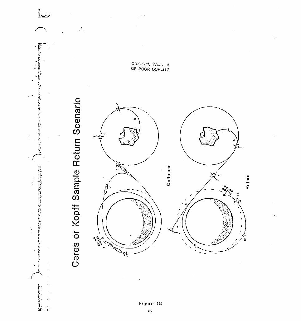
f"\
o --t-eu s:: (J) o
(J)
C !-::;,
-c-Cl> c: Q) -c. E ctS
CI)
I-o en <D L-
<D o
Figure 18
Q1
'0 c: :::l o .D -:::l o
\
"
c: ... :::l -o a:

.~
'w
:~
'Itt '.'.': .' .> '-;,,-,
o
, '
., ,
~~d fipacecr~ft will rendezvous with the cornet ~nd oelect ~ampling sites for undisturbed subsurface material. After sample !l i te nel ect i on the Sampl er / Lander it> deployed. An addi tional site is then ~electcd for the second Sampler and it is deployed. Once a s~mpJe has been taken, the sample return ~ehicle returno to the Orbiter leaving the Lander or landing gear on the nucleus. The LLnder continues to function as a ueather station on the comet.
The spacecc aft will prov ide thermal .lnd env ironmental protection for the sampleR during the trans-Earth voyage and as in the M~r5 Sample Return mission, it will be jettisoned prior to Earth orbit insertion leaving only a sample assembly in the Earth Orbit Capsule. The Earth Orbit Capsule aerobrakeG into Earth orbit and is retrieved to the Space Station with an OMV and placed in the Quarantine Module.
The general description of this mission comes from reference 8.
5.4.2 Spacecr~ft Mass Estimates
The mass statements for this mission are found in Table 16. As with the Mars Sample Return Mission, the masses arc broken down into systems:
o Barth Return System is the Earth Orbit Capsule (Ref. 17).
o La nder / Rendcz veus Systems incl ude the Nucl eus Lander and Sa:np.',ers (Ref. 8).
o Orbiter/Earth Departure System includes a Mariner Hark II Spacecraft configured for a comet rendezvous mission (reference 9) and adapted for the Samplers and Lander. This is a round trip spacecraft as it will also serve as the Earth Return Vehicle.
5.4.3 Delta V's
The delta V's used for the Kopff sample return were provided by Alan Friedlander of Science l\pplications. The Kopff sample return mission has not been extensively studied. As a result no window data is avail..1ble. Window data from reference 6 indicates a vari~tion of lO~ in total delta V required over a 20 day Space Station launch window for a 1994 Tempe1/2 rendezvous. Variation in total delta V over 360 degrees of possible station nodal locations WdS 3%, assuming best date launch •
Table 8 shows the Delta V's required. This is a ballistic trajector~. Aerocapture into Earth orbit with a circularization burn is used on the return. Kopff has a period of 6.4 years. A rendezvous mission to Kopff on its orbit prior to thi s one, launching in July 1990, has been studied.
82
: ... '
~
~: !1 . .
'~
:.
1 ~
I t
i • L
~
·t',-~
5.4.e Space Station Impacts
Two OTV' s muot be 3tacked, integrated, checked out, and fueled for this mission. The aerobrake must also be removed fro~ the second stage, which does not return. Table 7 nummarizes the impacts and the on-orbit manhours. Section!> 6.2,6.3, and 6.S provide more information on some of these operations.
As with the MarD Sample return misnion, the Quarantine Module caunen the biggest impact on the Space Station. The environmentally isolated Quarantine Module will be added to the Station to handle and ~epackage the returned sample in a biologically disaster-proof container for shipment. Section 6.4 provides more information on the Quarantine Module.
83

--
.. :;. ~:.t
• t>
It: . o !
'fable lii I Kopff N\Jcle~ Sa:r.plc Return Weight St..ltment
Dc3cription
EM'ltJ RL":'JP~I SYS'l'F.!·! El .. f;'lH W;: IT C\.fSl1.F.
St\.V.PLS rR~ ~~ ISSE!'ru;{ n~<"l.L'L'€S 1 0 KG s.r .. '{PLE
fJ:':I{mWu-::; :XIHlD
'lD'Ii\!.. COlI' I ~ (;!-! iC"!
?RO}tiLS1U:: S11!.:elUru: Pj{Ol-'!~LL .. \·'T
Rlli-:JEZVaJSI I .. ·..r;llHr. S,,)'S'I'f.H CRIll .. :!r. !-),\.'WLEH
SCI::::Q; ax:.':..',:;;) N.:TJ [W!'A I!A\'lLn~ 'I1:.:Ll:D)~:·'t:~;ICATICN t'.l\(:::::' PJ::N;r' rc~1 m=:-mor... SYS'lEM l-'(W·:R/ PYFO S'rnIJCIt'H..!:: :m:RYJ\L CU.:l'ROL CAI3Ll!'},; DE.VICES
~l.'b'!V!·N.
mTr{cx;!:~~ "mp£I.J..t'\.'l'T Q)!rrm:;r~~CY 13m)
D:< IlL I~ ;(; Sf ... ".PLL':{/ I ...... '-tT£R SCU;;cr. OJ~':>~l\!:O l\!J) DATA 11l' .. 'lDLINV 'l'1:l.:-:a::(:";'JNl eRr ION t ... r..cs REl\CfIU~ <Xlil'HOL SYS'IDI ro·mVpYRO S1HJC:n;;I.E 'l' 1 U~!'~\L ill: 'mar .... CAELIllj DEVIO'.s
84
Item (kgi Totals (kg)
60.0
28.0
88.0 4.0
92.0
1.0 9.2 230 Isp
102.2
0.0 1.5 1.2 1.6 2.4 3.8
13.0 2.5 0.5 5.B
32.3 0.9 9.7
42.9
14 16
11.2 0 0
30 42.5 9.6
5 10.5
-"
I
J
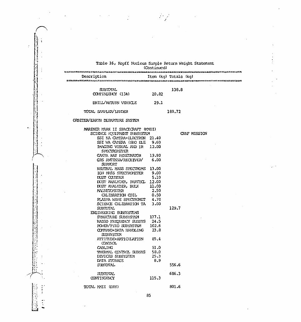
-
I
Table 16, Kopff Nucleus S • .1!T'P1e Return Height Statement (Contin~d)
Description Item (kg) Totals (kg)
ruD'IOTJlL alll'ur;E}JC'{ <1:5%)
DRlIliru.-WR-1 VDnCl.E
ORBITERlEAR'l11 DEPrumJRE SYS'Irn
20.82
29.1
MARINER r·~ II SPACEQW"T (f.lM!I) SCIf1~CE r.l'.1JIF:mlI' SlBSYS'IEM
55 I NA Cl\I>'"".r.RJ\+ I:LtO'Rrn 21.40 551 \';A CN'.EP.J\ (SilO I:LE 9.60 IM.';GIf~ VISUAL NJ) IR 12.00
S PEC'IRO!·!E'fER GN-C'A PNi PENf:IRA'IDR 19.90 GRS A."1I'~WRECEIVERI 6.00
SJProRT Nill'IRl1!.. HASS SPEC"lR)!I£ 13.00 IO~ /·V\SS SPECI"ncI1F:I'ER 9.00 rosr <XlP.ll'ER 5.10 rom' J\..>.U\LY<:ER, PARTlCl. 12.00 roSl' ANALYZER, BULK 11.00 Ml..GNE'l\y'~'l'ER 2.50
Cl\L IBRATICN ill I L 0.50 PLJ\S!.~ \"lINE SPECI'RCl-lliT 4.70 SClma: ClILIBRATICN TA 3.00 SUB'IDTJlL
EN:;INEERHC SlBSYSIEHS smucruRE SUBSYS'IU1 177.1 RJ\I)IO FRHJUlli"'Ll' stBSYS 24.5 IU'lf.R/PYRO SUBSYSID·1 102.6 ro·U>iFI."ID+-lY\TA HANDL IN::; 23.8
SUBSYSTrn A'I'l'I'illDE+ARI'I CUIMION 85.4
o::Nl'Ra.. CABI.HU 51.0 'lliF1~AL OJmI<Q. SJDSYS 58.0 DEVICES SffiSYSIU1 25.3 IY\TA S'lDRl'(;E 8.9 StB'IDTAL
SUB'IDTAL OlrrnCEl¥.:Y 115.3
'IDTlu.. z.rnI (DRY)
85
138.8
189.72
OW' MI55IOO
129.7
556.6
686.3
801.6

.. ~
Table 16, Kopff Nucleus Sample Return Weight Statencnt (COntinued)
---- .. =-==========:::=-===== Oescr i l-t i on Item (kg) Totals (kg)
========-===:::;=- - ---====
PRopur..srm: PIOPL'ISICN S'lWCIURE J{Q) IhJF'f-..l...Ltwr Dl-l..:JA V PRDPELI..At1l'
'ID'li\L !-Z1II (y., 1:.~'l
995.6 50.0
6195.3
= ==
8042.5
IDrloJ .. ll~H:crED \'iEIGIIl' 8376.4
AUl\PfERSi!'Hsa:;..w ..... u·n;s mUIPMEl1l'
l}\!.nD! VHlrCl.E l~ 146.3
'lOTtu. arv SEPARATION h'EIGIIl' 8522.7
86
rr=--========-=
2SB I!-1'

5.5 Ceres Rendezvou~/Sample Return
5.5.1 General DeDcription
The Ce r es Rendez \'ou~ / Sample Return Hi ssion (October, 1994 launch) mav be ambitious for 1994, but is included here to demonstrate cal)abil itj'. Al though their origins may be different, asteroids, like comets, represent relutively primitive bodies. A sample return will allow detailed analysis which should provide insight into solar system evolution.
The specific objectives of thi~ mission are as follows:
o
o
o
Return sample~ for analysis of moleculur and elemental abundances, conc.::ntrations ~f ices, physical state of surface material, local homogeneity, and critical isotopic ratios.
Produce high resolution topographic map.
Characterize the asteroid including size, rotation, albedo, mass, density, magnetic field, and solar wind interaction.
ThiH mission, including samplers and carrier spacecraft, will be the same as a Co~et Kopff Sample Return Mission, except the carrier will be configured for an asteroid. Figure 18 shows the scenario. Table 6 summar i~es the OTV/launch weight breakdown. More details are found in Table 11. Sampler details are found in reference a and MMII Carrier details in reference 9.
5.5.2 Spacecraft Mass Estimates The spacecraft is similar to the Kopff sample return spacecraft
except that the Mariner Mark II is configured for asteroid rendezvous instead of comet rendezvous. Table 17 is the spacecraft weight summary.
o
o
o
Earth Return Systems are the same as Comet Earth Return System described previously and in Reference 17.
Rendezvous/Landing System~ again are the same as the Comet missions. (Reference 8)
Orbiter/Earth Departure System is the Mariner Hark II ::;pacecraft configured for main belt asteroid observation ~s described in reference 9. This system is also the Earth Return Vehicle.
87
5.5.3 Delta V's Ceres trajectory information was provided by Science Applica
tions, Inc. (SAl>. A study of outbound trajectories was available off the shelf, but the return trajectory had to be run. Ceres outbound ballistic trajectories with no Mars gravity assist typically requi red 5 to 7 km/sec delta V's to rendezvous with Ceres as well as initial C3 's of 40 to 164. The best no-Maes-assist trajectory required it total delta V of 10 km/sec. These high delta V requirements, along with a sample return, produced unreasonably large vehicles, so the double-Mars-gravity-assint trajectory which han a much lower total outbound delta V requirement was chosen. Return trajectl'ries using Single and dual Mars swingbys were searched but the be~t trajectory found was only around 200 m/scc better than the optimum direct return, at the expense of 700 days added trip time. The departure date for a Mars assist return for the given outbound leg is in July 2000, meaning a 1.2 year stay time. 've therefore chose a direct return. Mars gravity assist trajectories exist for Ceres return legs, but not for our given outbound leg (ref. 10). Hore analysis might uncover a mission with practical outbound and return Mars gravity assist trajectorien.
Earth orbit insertion will use aerocapture with a circularization burn and Space Station or Shuttle rendezvous. An OTV or OMV would bring the s~mple to the Space Station. Return launch date would be adjusted to insert the sample into the Space Station plane.
5.5.4 Space Station Impacts
This mission requires a two stage stack and is very similar to the Kopff mission in terms of its' impacts on the Space Station. Table 7 summarizes the impacts. As with the other two sample return missions, the two OTV's must be retrieved, refurbished, stacked, integrated, checked out, fueled, and launched. The aerobrake must be removed from the second stage OTV, which will not return. Sections 6.2, 6.3, and 6.5 discuss these operations in more detail.
The returned ~ample will be retrieved to a Quarantine Modul~ as discussed in the previous missions. Section 6.4 discusses the Quarantine Mo~ule.
8a
""
",
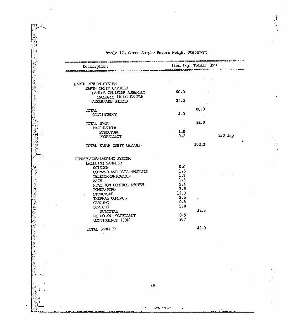
-,~ : ;.~Y--\ ~ . " .-"\' ~
1: -f l " ~'-~
'.- : .
·'f:·
;~.
Table 17, Ceres Sa:nple Return Weight Stat(!llcnt
====-======-=:;.;.:..::.;.::.:;:. __ ::--===---=:-==::.::.:::=---z:=.::=-=-= Description Item (kg) Totals (kg)
__ ========--=-===-crs:::c::::=:c r-- =--=-x=-=~-=::=::::--==::::r;=
EJ\.R'llJ RE'ltl~ SYST"...M FJ..P.'ru C!m1T CAPStJLE
SAHf'LE CJ\NISTrn JlSSEl-'BLY n~a..um:s lO KG St'\J~.PU;
ArnCl3AAKE SH I E::D
'lOTAL CCNI' ur; uo
'roT1\L (DRY) PROPlIlSlm:
SIRUCl'URE PROPElLl''!-;'T
TOTlIL EM'lll crullT CAFSULE
RENDEZVOJSlUI.\'DI~ SYS'IY.M DRILLI~.r; SAMPLER
SCIENCE ro.o.HJ\.':O J\.\D rRrJ\ HNIDLnx.; TELfXX)!,z.rumCATlO~
MCS REt.cTION <DN'ffiCL SiS'ffiM PO'lER/PYRO srnuCTURE 'IHERIW.. aNIROL 0\BLnK; DFNICES
SUBTOTAL NI'lRCX;m rn:JPWJ'\o.~ CDNTllKimcY (30% j
TOTAL SAHPLrn
to
89
60.0
28.0
4.0
1.0 9.2
0.0 1.5 1.2 1.6 2.4 3.8
13.0 2.5 0.5 5.8
0.9 9.7
88.0
92.0
230 Isp \
102.2
32.3
42.9
-=nPX;- syr""'l"ft
i • \ ,
f .
•
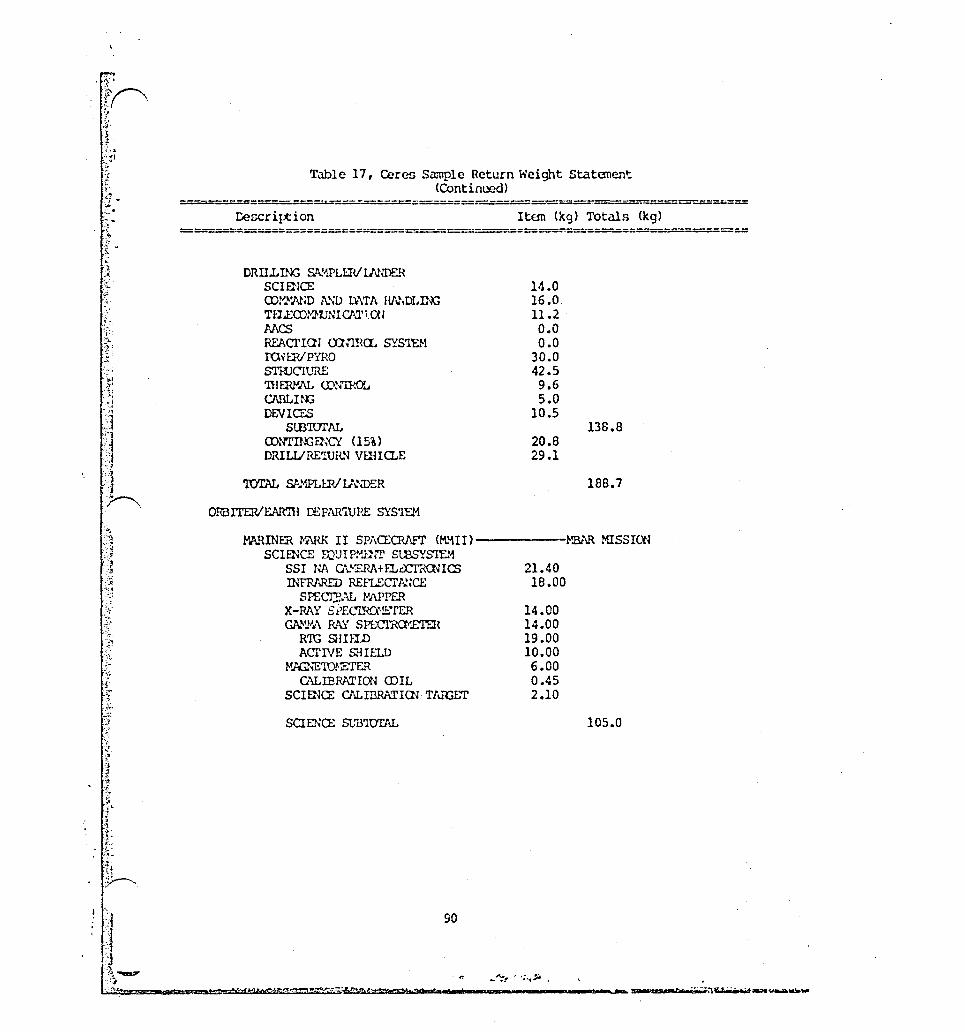
(; l' if '01
"'.
r l \; t .. ?: '';4
.~
T.m1c 17, Ceres Sample Return Weight Statenent . (Continued)
------r:====--==-----::;===~--__== __ ======
DRILLL~ S.~1PLrnI U'\N!)I-':'~ SCIEllCE mx.'lll.ND A."'D L\;\TA HN.DLIN; Tfl..E()}~LTNI CATi. W MCS REACl'IOJ firma.. SYS1El-i ro.·H:r<l PYRO SYNlC'IURE 'lllffilll\L CD~'1ROL Cl\llLUli DE.Vlcr.s
StB'IDI'l\L mNTn~FJ~Ci <15%) DIUu/REWHN vunQ..E
ORDITERlEAR'IH DEPA.'l'illHE SYS'lU1
Item (kg) Totals (kg)
14.0 16.0 11.2 0.0 0.0
30.0 42.5 9.6 5.0
10.5
20.8 29.1
13S.8
18B.7
l-'A.-qINER foi\HK II SPACEQWT (M.'\II)-------~!Bt\R MISSlOO SCIENCE mUIWJ1-rr SU3SYS'lE!1
S5! NA G\'~:EI'\A+F.LcX:I'RClncs
Th'fRAAED REFIECl'!':'~CE SPECJ:?,AL PAPPER
X-RAY St>EcrRCN!:.~rER Gk~l!}.\ R.A:i SPE;crna.lETER
RTG SHIEll) AC"l'IVE SHIELD
"'JilNE'ID1'~fER CALIBRa.TION COIL
SClma; G\LIBRATIrn TIUCET
SCIENa; SJ,,'B1DTAL
21.40 18.00
14.00 14.00 19.00 10.00 6.00 0.45 2.10
105.0
_c---- -:=
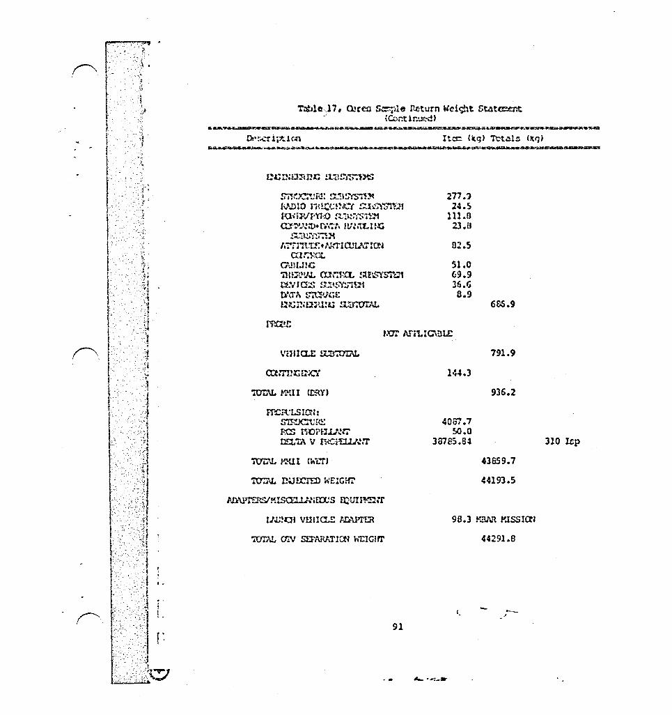
r-".,
:1 ;
". ~.
',} ~le}7, ~rez ~le r...cturn Weic;ht Stllte.:er.t (Co~tir.\,l!;.-d)
!i.,,\DIO liHt{;n.JC( !U1;"t~Jf rOim/f'U-';> !~·'H.!;-i$n~ C:l',!:".;tlw.r;\~-:. f1i:otLlrG
!Ul!.:~7IDt 1.'!"Z'l't11':.! ... ;"TIOJUJ:ct~
m::1-.'Ct C\Hl.m::: -nu~vJ. cn::,t!L !U\S'iSTh.~ r::t:ll Q.:'S !,Ul!;'l'!.o' ~]1 t5\Tt\ !.m'j(;t u;c~,mu:~ !l:;r.t:TU~
Imn~LSIO:: S"I!~Jcru ru-; Res rroi'f1.u'!~ D!L "rA V flt':r~:r
91
217.") 24.5
111.6 23. fJ
02.5
51.0 G9.9 J6.G 8.9
144.3
4067 .7 SO.O
3B7S5.B~
6&5.9
791.9
936.2
43£159.7
44193.5
96.3 Y.BI,,~ foussra:
'.
44291.8
-.'
.• ~ ·,,_a·
310 up

f'\
!"'.
r---. !
F
I .. I-I- . 1-'
r r. [ r t· r
.:~':'*:
.' . ", '-~ . . . "; .
,','":""
. '.'-
""1 '.~ "
", .J --, .. ~
. >i . " :r
.. i~
'.; .;
5.6 Mercury O~biter
5.6.1 Genecoll V-e!!crLption
The Hercury Orbiter nlGuLon (June 1994 l~unch) I!! n !ollcv-cn ::1o:;lon to the MilOner 10 £11'1.>,11 in 1974. An otblting np .. lcec:h!t .)110\01:1 c! one :It udj' of I'!crcur-," II topal ogy, !::orphol oqj', ~lner"'loqy, ~nd ~~qnetlc !ield ~nd ltn lntcrnctlon With the Gol~r wind. A dot~11ed nur!~ce =cp c~n ~lso be produced.
No retcrenccG wcre loc~tcd ptovlding apcclfic nclentl!lc objectlvon tor n Heleuri' Oebito! ~lonlon.
rlljure 19 ahowa the ::\1:~:l10n scen.Hi0. The :'!ll!l!lion c.-sn be tlown with one O~ which relurnn.
The wc19ht ct~tcoent Cor the Mercury Orbiter In cont~!nod In T.1ble Hl. ,\q..,ln the :,,!,'w!>cn Me d1vlclr.:-d into nyote~c. There in no Earth Return or nende~voun/Lnndlnq Sy~te~ for thiS 010010n • The Orbiter/Earth Ocp.'lrtlJrc Sy:;tc::J 1:: .., K.Hlner H.lrk II n~cccr.'l!t. SincQ there dtC no det..,lll"u tlcicnt1!1c obJcctlvco, no uP't,cH1c lnGtru=-ont~tion h~a b~Qn cclectcd. The veight ou~ary 1ncludcn 011 o! tho inutrt!~cnt~tlon chown in rdcrc'lc{t 9.
S.G.l Delta Via
Tho Oclt~ V'a u~cd for the Mercury Orbiter ~ir.nion co~o fro~ re!ercnce 6. Window d~ta !ro~ rc!crcnce 6 allows un to Del ect .l vor Gt C.1:;C. The wcr fit Cll&e cho:lcn ~r,su::e& launch at the worst posciblc ntl1tion nodlll 1oc~t1on, ~ut I1t tho opt1o~l launch dl1te. Table B ZhOW5 the no~ir.al dnd worst C4~C deltn V'G.
5.6.4 Spl1ce Stlltlon I=pl1ctG
Tho onl~' lelpl1ct of thi ~ ~l&Gion on the Sp,lce Station in the effort (!lho",n in Table 7) required to rcfurbinh, intcgroltc, checkout, fue!, 1 aunch. 11.,d retr iC'Je one 0'lV. Thin tll1kcs the Mercury Orbiter mission virtulllly the aJ~e as any Geosynchronous O~J ninoion. Sccticns ~.2, 6.3, I1nd 6.S dincuns these operationn in core det<lil.
93
.... _--

") -) 'J . /
~~~'-...... .....--"...,,~-- --~-,-. , ~'-~~""'''--'''':''''''-''''''''' "----~-~---,-~--.--.,.....,.,.-....... ~ ,I ," , "', )' I ... ", "r, ' ." .. '. '. . • , ' , l
':.. , ' , .. , ~ . ' , . , . . ' . . ' . . .
, , . . ~ »:,:)':,~';. "L:;' ~::" l)..;'!i-oi., :i""","1t'>'J':"~~ t ... I ... .;.;.~ .. ~~~· • :.. • .. , .' \~.p'.. ".', • ." >'~ ., , •• ,> • ~(( ". ~~;;,c.q,~~·.~-4I'~'~~"""*"'':j,.I'W~I;~> __ ~""" ___ ')_:",,,.,~,, .;. ... " ... ~~ .... ..,v.~ ~,....t~o;t,.o:o:.~,""f ~11o/.,.., .~"'J. ~ ~ .. -:,..1: en! ~ ~.~-{, "' .. .w. f1.; ...n- .. ;! ,f; I '-i'''' 01 f .... t.-.-« .... ,'/ .... ~.>.,~:~ .
J ___ . I', .. ,...... ... .., •
'j' ..
ID ..,.
MERCURY ORBITER SCENARIO
1.
2.
3.
4.
5.
6.
STACK DEPARTS SPACE STATIO~
TRANS-MERCURY INJECTION
OTV RETURNS TO SPACE STAT IOU
TRAt,S-frl£RCURY VOYAGE
MERCURY ORBIT INSERTION
DATA COLLECTIOt4
F,GURE 19 lEGEtm

0'1" ':
r· t I . 7 ,,'
l..
o e_
'-co c: Q) CJ
CJ)
Figure 19
95
..... -- ...

",rJ- . , Ie 'jj ,J,
- " ~
..
1_,
r: f .
l:" , .- ..
. ~.
! '
1 • r-\[, " , I , I >.
t.-;. :
, '" ,;11
., .. ,
. '~I ",J
- P:
: ,,'!-, ..
- ~~;.
; '·t
Table 19, t'.crcury Orbiter Height Stat~..cnt
~..cription It~ (kg) 'l'ot.:Wi (kg)
lm APPLIC"illLE
r':"Jill~ Hl ... G.lt I I SP.\crQ'?lJ'7 Ct.zU I) SCU2~ UXJI PHlln' Sl~S"I'U1
SSI N.l\ G.HE?Jt+fllX:lnanCS SSI H" Gl..IIJ¥,,\ (UlO u.n:::r) IPl.Gn:c VISU1\l~ NJ) IR
Sf":.'CrnO:·e.t.:fi:R n~'PAlill) ru:FLEcrI\!;a:
Srt;C1RAL I';,WPER 'IHO'J?J. IR SFZcrRl'...L
PJ\DIO:zn:R X - P.NJ. SI'ECI'R\I·:£."rr.ll G'U'.;~' PAY Si'EC"mJ1-:::rER
Rro ~IIEI.D l\crrvc. mam
GI\!'~·Q\ p!\Y PWi:WJUOR GRS l~nu~W'fu:.-U:IVmI
ruPro!n' NIlnpJ\L g,'\...~ SFECmaerrn 1m PJ~ SPEC"IIa~J.t:R rosr <IJU!lIrn IlJS1' 1~W.'iZ EP., PARl'I Cl.E tuSl' AN .. \L'iZ En, BtlLK Il.lST a::ILCIDR EltER:;E:!'IC PA.trrIa..E IX."I'EX:'!OR K.l!G\£"fCX~ fo'l{;NE:IU ... .!:.*l t..~
Ct"..LIBP.ATlm (D IL PU..s""A WAVE SPECI'P.QJ.E."n.lt PL1\S. ... .A N U'..L'iZ ER KJ\S!-,~ rilNE Nw-yzrn ffiO'IDHETER RAn\R rAPPER PADro scrma; SCIUlCE CALIBRl\TICt~ 'l11ffiE:!'
96
21.40 9.60
12.00
18.00
8.00
14.00 14.00 19.00 10.CO 19.90 6.00
13.00 9.00 S.lO
12.00 11.00 5.00 9.00 6.00 2.50 0.45 4.70
10.00 6.~0 5.00
28.00 5.00 2.10

(' .•...
1 . ,d:
-', }: .
":'" ..
Table 18, ~\cr\!Ury Orbit~r ";el<j.~t Stlltar..cnt (Continut'd)
OCIO~ C\LIDRATI(l~ 'U\.t{;IT SCIUK.:E ClLID.RATIOJ TI\IGl::r P;J)IO f<iV,¥ II.A.Gll/M<.E
ru:a;IVER P.t"IDIO HilA¥ IW{O'l'f.JU::
Ntrf!::,,\ SCIU;a: !lI'Il'IUrAL
SlVL'CIt:HE &,'BS'i~'1ut R.\DIO f1U.l)Ut:O StDSYS"I1:tt roi~./PYRO S}!J,!,i'S1Ut CD. ... !.'W~flI\T" HNi!ll.UJ:;
s"'USY sn:. .... ,'\TrITh1."€ of f.HTI aJucr I eN
<Xrlffi01 ... Clill Ll:l;; 'niER."'JJ. ro:I'na.. stnsYSlDi Df.VICY.S st:E~lSTh."i I}\TA !>"'ItF1C,E fl'~nlWU!.G SJ'DTC1Ii'\L
'l'CJlJ\L P.Ml I CDRY) l-roPULSlm:
SIRUCIURE Rei roDPflll ... \'T rE!:m y mo?ELI.J ... 'tl'
97
Item (kg) TctalG (kg)
3.00 3.20
20.08
3.06
315.1
207.7 s::Jrr! MISSION 20.0 rorP mSSIa~
102.6 OUI.F MISS!a~ 23.8 Gl1CmAL
85.4 ~p rUSSICN Ch'C)
52.0 SOl'P mssra~ Cl'>'1:) 76.S m'JP lUSSlal n,"C) 36.6 I!'N..F lUSSICN H'.\:) 8.9 GfltERAL
613.5
928.6
150.0 CASSmIDJ)
1078.6
585.1 50.0
3915.6
5629.2
299 I!;p
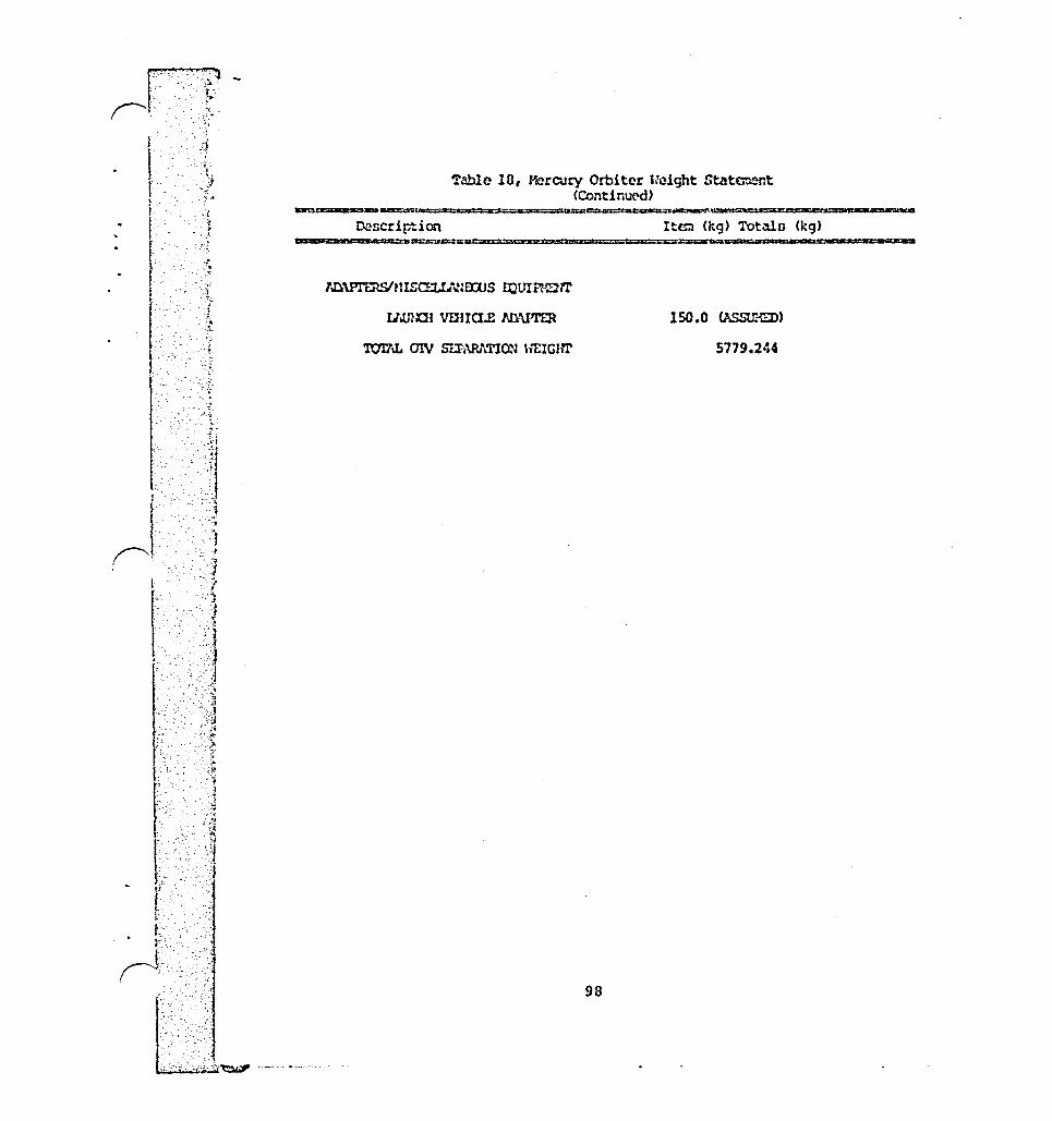
I r I f
f t, i,
I
t,
I ('.
l
i'"
'. ~;;: , .. ,)
~:
., . . " I'·'····· I -:ij
(' :. ',.1
~£cription
Table 10, ~rcury Orbiter "eight Statement (Continut'd)
Item (kg) Totaln (kg)
5779.244
98
. c:: . ".1.1
.:: ,.
I:
t [ ......... .
re'
5.7 Saturn Orbiter/Multiple Titan Probes
5.7.1 General DeGcription
The Saturn Orbiter/Multiple Titan ProbeG mission (Apr'.l 1993 launch) will provide detailed infornation on both Satur: and Titan. The Saturn Orbiter portion of this ~isnion wil. help us better underotand this a5se~bly of satellites, fiel. phenomena, rings, and giant plunet.
The npccific nbjectives incllAde:
o Deternine three-dimensional ring structure.
o Characterize natellite compooitions.
o Measure three-dimensional magn~toGphere ntructur~.
o Study the behavior of Saturn's at:nosphere at the cloud level.
o Detailed studien of Dome of the satellites including regional mapping of Titan's surface.
The Titan probes will be used to study the atrnonphcre 0 Titan at various locations. This atmosphere io believed t· resemble the pre-life Earth atmosphere.
The npecific objectives of each probe include:
o Determine the structure and chemical co~poGitior. of the atmosphere.
o Study the exchange and deposition of energy with the atmosphere.
o Characterize the surface morphology on a lccal basis.
References 9 and 11 contain details of the science objectives Figure 20 shows the mission scenario and Table 6 shows the OTV/launc weight breakdown.
S.7.2 Sp:~cecraft Nass Eo;timates
Again, a Mariner Mark II spacecraft will be used. Referenc 9 shows the configuration of the spacecraft and reference 1 provides the d~tails of the first probe. The additional probe will be the same except that they will have the propulSion require for deorbit. Table 19 contains the spacecraft weight breakdown The Earth Return System is not used for this ~ission. The Rendez vous/Landing System includes the probes, and the Orbiter/Eart Departure System is the HMII spacecraft.
99

) . . ~ \., ,', '\,' • ">t,'/f, • .... ,~, .. '" . '.. ::. .'. ",<, ""', "~'. ". • .:,". ,.' ,~ .. ~
[I ......... -.~-,-. .,....--..-, -'. :or. .-~-.......;.,-.,.....;,;-- . :':",-~-,~"""""""" , ...., ------
:. ',; .~··~i~':·" '<~...: ,.~:/.:;:·\,~:.>".:.:":~.;:<.~:..,::.i.)~~.';':'.i"'.;r"",~ • ...;......:.~;.;...:...,;.;;; .. _.:.... ',;" ,'",' :,.,: ;.;...;;~~~ .. .;:~;..:;,:,,-,,;;> ..... ,;,;'t';:";'>;"""":;":<'::l.~;::::.;::!· ~.;;:;t:/;;;,(.,·· I
.... 0 0
SATURN ORBITER / TITAN PROBES SCENARIO
1.
2.
3.
4 .
5.
6.
7.
STACK DEPARTS SPACE STATIO~
TRANS-SATURN INJECTION AND OTV SEPARATION
TRANS-SATURN TRANSFER VOYAGE
RELEASE OF FIRST PROBE FOR DIRECT ENTRY
SATURN ORSIT INSERTION AND ENTRY OF FIRST TITAU PROBE
ORBIT SATURN
RELEASE SUBSEQUENT TITAN PROBE
FIGURE 20 LEGEND

o lO-t-m c C) o en
Cf) Q) .0 o t=-o. C C\S ~ ...... t-
~~/ w . " ..
~" ~ (\I , .. ,>-
~'~
....
,
\
I
?~ .. ~~~() •.. ~~._. o~
_ . ,-:,~.l- ..... 0
Figure 20
101
1
1
1
1
1
1
1
1
1
1
1
1
1
1
1
1
1
1
1
1
1
1
1
1
1
1
1
1
1
1
Al . "
5.7.3 Delt~ V's
Titan Probe/Saturn Orbiter trajectory information was supplied by SAl. No window data was available. Reference 12 contains other potential mission daten.
The Saturn Orbiter was placed in a 1.51 x 105 by 24.4 x 105 km orbit around Saturn with a periapsia burn. More study of this ar~ival is required to insure the timing will work out. 1.51 x lO~ km ia 2.5 x the radius of Saturn. 24.4 x l~~ km is the ~:bital altitude of Titan. Insertions int~ circular orbitn at these two altitudes were also considered but required much higher delta V's.
5.7.4 Space Station Impacts
The aerobrake of the single, one-way OTV boosting this minnion must be removed. The mission can alno be flovn with the aerobralte on \lith some payload penalty. The OTV must also be refurbished, stac~ed, integrated with the payload, checked out, fueled, and launched. More discusaion of these impacts in found in sectionn 6.2, 6.3, and 6.5. Since the OTV does not return, another must be launched and assembled. This last operation should not be charged entirely to thin mission hO\/ever, since the reusable OTV's can only be used a limited number of times, and will have to be disposed of at the end of their lifetime.
102
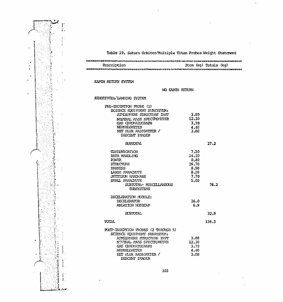
- . - ~
. r - .. ,~
Table 19, Saturn Orbitcr/Multipl~ Titan Probes Weight StatcmE'nt
""" O::?scription Item (kg) Totals (kg)
==::z:==:z:::==:::::::;:=:co:::.=:::: ............ ==e=-.::::=:::==u:::::==========;===·,====
EAA'IH RE'IUFN SYSTE.,{
PRE-n:~ERTJctl mooE (1) SClmCE EX;UIPHENT StBS'ISl'E'1:
!a:"OSmrm; S'IP.ucruRE n~Sl' NE1J'IRAL H:\SS sPECIPO!€I'ER GAS QIIO'A'I{X;Rl\PU NEfliELQ'\XI'EH NlIT FLUX .Rl..DIC»!ETER /
IJfScmr nt!GER
SUB'mIT\!'
ro~~·lJNIQ\TION n\TA HlINDLI!~ FaVER STmC'ruRE HJ\RNESS I.J\ffiE P,'\AAOn..'TE JF.Tl'ISc:r: l!t'1R!l':ARE SlWL PAHAO!tll'E
SUBTCJrAlr- MISCELLANmJS SlBSYSTEHS
DECELEl<ATION mOOLE: DECELrnA'roR AaU\TION U::lSOCAP
SL'B'lU1'AL
PQSl\-lNSERTION ffiOOlS (2 'nmaxm 5) SCIENCE muIPHENl' StBSYS'I'.E2'l:
lmDSFHrnE S'lFlJcruRE rnsr N?"l'IRAL HASS SPEcrroHE.'1'ER GAS QUn~ATO:;MPH NEPHElDMETER NF..T n.UX RADIo.'1E'l'EH /
DESCENl' n%ER
103
3.BO 12.30 3.70 4.40 3.00
7.20 14.20 8.40
16.70 8.90 8.10 7.70 5.00
26.0 6.9
3.80 12.30 3.70 4.40 3.00
27.2
76.2
32.9
136.3

\
: . ~;
'. \',- '.'~ ;
.'.," -. ..~ ',j - ..
~.", . ~:
t " '~~i .~!
Table !9, Saturn Orbiter/Multiple Titan PrOOes Height Statement (Continued)
================== ====-~=====z<====::c.===~==== Description
CD:"UNlo\TION Ik\TA HANDLUJ::i roiER STf1JL~E UAPJm3S ~ PMAonm; Jf:lTISm ll~ARE SHAlL P1\R1\Olt1l'E
SUB'IDTAIr- HISCE:LI..ANroJS SUBSYSTEr1S
DECELERATION r·OOOLE: DECl'l..ERATOR ABU1TlOi'l ImfAAP
SUB'llJ'Ij"IL
DOOPBIT FROFULSla~ SJB'1Ur1\L (BUrGET 10~ OF mmr HEIGm')
'ro'rAL OF 4 ~rnSERTION ffiCBES
ORBITERlFJvmI DEPAR'lURE SYSTIl-t
l'.i\RINER W>llR II SCIEl~CE mU1PHENr stBSYS'IEl<iS
SS1 NA Q\h"ERA+ELOCl'RClUCS 'IHERHJIL 1R SPEC'mAL
RADIO:1ETER OOSI' n.:.~R ENER:'-E1'IC PAm'ICl.E nsTECroR MAGNm:or1ETER
CI\r,IBPATlrn roIL PLf..Sl·v\ J\N1\LYZER PIASMA'rlAVE A"U\LYZER PHaro..v.ETEt'l RADt\R I'TU'PER AADIO SCIENCE
104
Item (kg) Total!l (kg)
7.20 14.20 8.40
16.70 8.90 0.10 7.70 5.00
2f: .0 o.~
21.40 8.00
5.00 9.00 6.00 0.45
10.00 6.00 5.00
28.00 5.00
27.2
76.2
32.9
136.3
272.6
1090.4
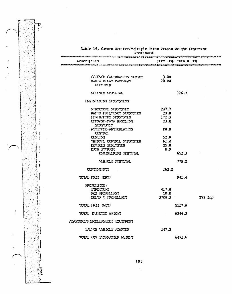
"
][ ·;1 [
'rwlc 19, ~~'tl.!In Om!t(':/~ltlr-16 Tit.l.'l ?:(0e3 V.c1t)ht StatC't!!rnt (Ccr.t lnUl'd)
x: ma: c\t.:rmt:rretl ~JCL7 R. \fJl 0 )zll" '( t!J\.t1.};Aj'.!:
fUu:r:tJ"t
~m~~~~,,~H!: !:"'!~J~:!'1
Rl':'>lO fHt!!!~Jl..~ ::t,~!<1 iUil1VP'tiO !l..!lSl"$7U1 OJ:r-J~~)t t';\.~ ItN~t.I:.c
h'l'Tn .... ,.'t£. ;\.I.,-rl an.lJ la~ 0l::r.0.:.
a,,!.J1 •• :!~ 'nU~J.t. car.1-l.~l. !:~\;.":i~.1i UNI\J';:; s"!I!i)'S'rUl n\7~ S7Q>,J'1GC
f~.t; n. ~Jtm:; &tr:ttr:"J.
ffiC?n.s:cr:: S!!1J'C':\: ii£ Fa; Iro?:l.J),..!n' DEL'l? V n1<..)a:u.I"ur
IDS
3.00 :co.oa
2v7.7 2"0.0
172.3 23.0
eo.s S2.0 61.0 25.0 0.9
162.2
417.8 ~.O
3709.3
147.3
652.3
779.2
941.4
2sa I.tp
5117.6
6344.3
6491.6

r '\'~i ¢r;t
f'1.··.·.· ..••. ·······} t -"·r I
L ;....,..
I .'J
I, I '~ 1 . . ~'J-[ ;~ t .~
r·~ , . "r
r:·.:.· .-~ ~ . /~
!L,;~~ ,--~ r , i· I'
I···.· ! l t~
t i I , .' I' r----. !' ( '. r L r
,-. .. -- ,-
'.
s.a Sennltivlty Studlcn
The nenaitivity of the Earth taunch WQlght ror each of the five bent C~tl~ pl~net~'y ~1D6ionu to 13p, inert weight, and propclllsnt C.'1P.lCl ty W.lfl cX.1:'>lncd. E.lrth ltlunch contD .lee the 1~rgc3t nU~b~r in eany cvcr~ll nyntc~a of thin n4turc and their relatlonnhip to other p.lr~~et~ru 1n the upper ct~gea ot the nyntco in .'1 quod firet-cut indication of tho doll.lr vlsluc of devclo~ent week.
Tho b.'ltH!'llno Itlp ullcd for tho Oi:'J L02I112 e-nqinca 1n thin Gtud~' \of.,!) .l cont>~r ... .,tl ... t' 45:' oeconi.lo '!ro~ Re!. 2). n.li!:lnq thlu lop to 4aO cecont!:1 reduced tho totol 4\·er.lgc f:.uth launch [(-quire!'!~nt for .111 five r.lir:Ulona bj' s.,n. The tot<ll .'1vero9t: propell.3nt lO.ld for thQ !lve :::1tH.lonil thllt could tH~ lounchcd by it ULV <lropo by 9 •. ". The nUH:.lon!l with the hlghcnt C)'3, tht' !\opU .lnd 'iit ... n ~lr.nlonG, \Jere ll!fcctcd tho ~O!lt, w1th propoll.lnt lo~d rcductlonu ot 11.3 ~nd 10.5 'rcup~ctlvely. Thene propellant cQductlonu do not n1gnl(icantly ~!tcct the ovcr~ll Gccn~r10 or J.tu l~p.lct on the Spolce St:1tion. 'Tho nueber of nt~gea, thd r oppro~l~atc nl:~, nnd the opcratlonu that ouct be done roooin tho O.l~c.
Th~ total prop~llont required for ~11 fiva mianiona vac 221.1 ~etrlc lonn. Gl~en a ULV Cop~blc ot l~unchlnq 100 petri~ tonn of propcll~nt ~nd cODting 13l cl11ion dollofn por launch, tho COGt to launch 221.1 netric tonn of pfop~llant lu 294 million dollarc. An lncrc.lOe in OTI Inp to ~BO &econdn would reduce thin 9.4 , (or thcne elVe ~i~Dions, cdvir.g 27.6 pillion dollarG, which could be utied for engine dcvclo~cnt. The 3",:::e calculation::; uuing only the Shuttle (or tranGport renult in a 75 oilllon doll.'2r sa"'inq!l. The ~uch tiore nu:::erous OT': miZ3ion!l to GEO And the Moon wlll produce other ::;~vinga fro~ lap incre~ne, wl.ich will be the do~in~nt nu=bers.
An -Inert Weight • A + oe(Prope11.lnt Weight)- equntion fro~ reference 2 was uned to deter~lne inert weight tor the OTVt~. The A ter:n includes the weight of the aerobrake, en~ineG, And other non-propellant-dependent structure. The 0 ter~ accounts for the tanks and other propell~nt-dependent structure. To check the censitivity of Earth-launch weiqht to OTV inert weight, the A nu:ber was :educed by 1/3 from 3,731 kgts to 2,487 kg'S. The average total-Earth-launch weight for all five missions went dovn 7.1 ,. In terms of cost benefits thin reduction is sir.:Har to the prc':iously discussed lap reduction. 'ihe launch weight reductionu for the individual ~i£sions were MSR - 7.5 \, r.opf! - 9.6 %, Ceres - 2.1 \, Xcrcury - 10.4 \, and Titan - 5.7 \. I'\S .... ith ttle Inp change, this inert weight reduction did not change the Space Station inpacts.
The baseline OTV propellant capacity ~a5 40 netric tons when this nennitivity study .... as don(>. Late" in the t;tfJdy the baseline was changed to 42 ~etric tons as the vehicles were refined. All the tables and figures no.., reflect this change to 42 netric tons, but the scnsiti'Jity nU::!ben; do not. Since the change frc~ 40 to 42 r:etric tons ~akes no significant difference
106
....... __ ..... - --- ~ ........... ,
in any of the conciuuiono d:awn 1n thin aoetion it "'3D not neccnnary to r~run the nu~bcrn.
To detcr~in~ the ct!cct of ~ niqnlfic~nt ch~nge in pror~llllnt c-lp~clty, the pl.'1nct.lry n1on1on nuobcrn were rerun wlth " )0 I!\ctric ton propcll.lht C.1P~Clty OTV. Thin ch.,nqo :=.,de a n1gni!ic4nt d1!!ctt'ncr.. The "opt! llnd Ceres Sa:~plc Return tHaalonll both rc-qu1 rcd three M4qt:U 1 nr;tcJd of tvo, and tho 71 tan r-robC:J/Saturn Orbiter Minnion r~qulred tva ntagen lnote~d of onc. Since tho lncre4ccd co:::pl ",xl tj' of thin llrr,'lnqcoent V.ln ~ercc1vcd no undcnir,\ble, the etllc~ dcu191'\ wlln not purllucd. ,\pproxi\':1ate totnl E~rth launch weight lcductlonD (paylo~d nnd propell~nt onl;,') verc, hO\iC'Vcr, cillcul.'ltcd in the r,'lngo of 3'.
107

~- .. , . '., ' ...
. : .!
5.9 Planetary Hinniono fro~ ~Jn~r Orbit
It in ~ widely held belief th~t there are cubntantial performance bcneiit5 dGcociAtcd with departing fro~ the ~oon u&ln9 lunar produced propellant to r..cricrr.: pl~nctllry exploration due to the nh~llow lun~r qr~vity well. Thin in not necennarily true {or thC! C.3IJC where the fuel (1!2) ~unt be brought fro::\ Earth. Connider the following:
1) Tho t'loat eff tcicnt rcogull.r dep.lrture t:'\ode (or trono!e: {rom lunar orbi t to lin interplanctllry C3 in vi., low £~rth orbit flyby with a mlnl~u~ delta V lun~r to £l1rth tr.lnsCer ontS a burn fro::l a parllbollc to hyperbolic Earth orbit at perigee. Thic yields II total ccp.:lt'ture delta V f[o~ the Moon a conntant 2 k~/o~c below that fro m 1 0.... c icc u 1 ."i r E.lr tho r bit ( w her e the t ran G fer io from the circle onto the na=~ hyperbola).
2) To dcp.ut feor.! lunar orbit, hC1Iever, one munt firnt get there and ~ takeD a total of 4 k~nec. In2f~ct~ for a cargo orlglnating at E~rth, a C3 of 30 k~ /scc can be reached for the n~=e delta V au 901n9 to lunar orb! t.
3) If lunLlC oxygen i5 avail.lble for propellant with terrC:ltrial hydrogen fuel .It a 711 mixturc r[ltio, it t<lkeo approximately 3/4 of a kg of propellant in low Earth orbit to provide the fuel (hydrogen) portion of one kg of pro?ellJnt in lunar oroit. This is co~posQd of the hydrogen UGcd in launching the lunar O~, the U2 to be burned with the lunar 02 to dapart fror:t lunolr orbi t, and the L02/LH2 propellant to transport that hydrogen to the Koon.
4) Because ~or~ total delta V is needed if interplanetary departure of an Earth-supplied payload is made via the Moon, ~nd because lunar derived propellant expended in lunar orbit requires 3/~ths as much propellant to be expe~ded in low Edrth orbit, all of the unmanned minsions exa~ined in this study rcquired more total propellant expended in low Earth orbit if lunar departure was used than for direct derarture from LEO.
This proven true for any Ea~th supplied cargo until C3 is at least above 80 (km/sec) • There if:> a theoretical breakeven point for -rubber- stages at a C3 of between 80 and 100 where the mass in LEO becomes less for lunar departure. Thi5 C3 range is above the energy of the missions of this study.
5) This docs D.O..t dincount the posf:>ibility of oupplying
106
t ! I·
t
lunar O2 to low Earth orbit. Thin option mny be attractive to reduce tne ~an6 rl~ulred to be launched froo the Earth'n uurface.
6) Only if a ciqnif iCllnt perccntolql} of tho interplanetary cargo itoelt in lunar-produced doen any adv~ntage appear. Th i 5 now appf':ar 0 to be the cane onl y for npacecrllft utilizing L02/L.U2 propellant for ?O:i.t inncrtion ~"nucvcrn.
~n cxa~plc of thin in tho caGe of a ISO ~etric ton manned H''1r3 minsion c\'\-Jule proposed by Gordon Hoodcock an an clement in ono ~:~po~ed HarD mi~~ion nccn~rio. If that woight includod oufficicnt cryogonicn for Harn orbit innertion and trana-Earth injectiun, then 3/4 of the na&n might be propell~nt with 65\, or 96 metr ic tonn being oxygen. I! the vchicl e dCpllrted fro::l Earth, a total of 360 metric tona <including PJyload) aro nceded in lov Earth orbit.
If the na~e vehicle departn from lunar orbit via Earth flyby trajectory and UDen lunar produced Q~ for the 95 tonG an well ao for interplanet~ry inject10n, then only 276 ~etric tonG arc nceded In E~rth orbit including the U2..., nhlppcd to tho Koon for the lunar lcl~ncher, etc. Inc savings i5 90 cetric tonG in Earth orbit, or 01 ightly over 25\. To Olchievc this, a total of 230 ~ctric tons of lunOlr O? must be produced and u~ed and 5 50rtie~ of the reucaole lunar lander floun to deliver the 140 tons of lunar oxygen to lun~r orbit.
Whether it in possible to produce 230 tons of O2 on the Hoon and fly 5 nor ties of the lunar launch vehlcle le~s c~pensivcly than producing 90 tona of O2 on Earth and launching one un~anned launch vehicle tanker is an unanswered question.
There oay be sorne cost advantage to lunar operations in this instance but it is certainly lUl.t overwhelming.
If a suitable lunar fuel can be developed to go with the lunar O2 , then this relationship may change sharply. A lower Isp might be acceptable if all of the propellant could be produced from lunar resources, but this possibility requires further study.
If a source of lunar hydrogen, such as the postulated lunar poll! "cold traps· can be located, the need to transport hydrogen from Earth to support lunar and planetary mission operations c~m be eliminated. In thin case, the use of lunar-produced 02/112 propellantn becomeG a ~ attractive option.
109

r \ I I /"
. -.t. )
, 1:" "';4-
. "".':
"
" ,":-t ... -- ~ ... ~
"'
" .. ::(
6.0 D!ncuoslon of Individual t~p~ct9
The ~ajor i~pacta of luna! and planetary miG~ion8 on the Gp~ce Station can be c1cscribed an relatively dificrctc elements and effectn. Although oany of theDe i~pacto have been dencribcd previol!oly, neveral rcqui ref ur ther dincuooion, npec if ically: the O'IV hllng<lt' and maintenance !l2cll ity, the propell.:lnt storage nnd trllnnfer facility, the O'lV rn,Hing .1nd ntackirig g..'1ntry, the Quarantine Module, and O'IV r.lllinten,'lnce .. Jnd refurbit;hrnl!nt 0Fcrationg. The follo .... ing paragraphs deccribe e.lch of thou'?
The OTV infr~ntructure in ito entirety nhould not be connidcred an inpilct on the Station. Tile np.lce bllced, rcutlllble O'lV nynte::l molY vell be put in plllce firnt to cervice gconynchronoun orbit missionn. The lunar baoe may ntrongly influence the Wily tht' Di'otem in built, but will hopeCully not have to pily for it llli or even the maJority of it.
6.1 OTV Uoln tJolrn
An OTV hangar is she .... n in Figure 22. The molln truDs, shelter, and ohelter ntructure arc clcolrly visible. A OM" in seen in the lower left portion of the hang~r and the Remote Workztoltion in in use parforming a visucll ior-pection. The OTV U.lngolr in perhaps the nost visible of all the imp~cts on the Sp~cc Station. Thin fc1cility is olsnuned to be located on the Spc1ce Station keel just beloy the transverse boo~ consistent with th~ JSC -reference· Growth Space Station. It is attached to the starboard side of the keel to allow full mobility of the Space Station Mobile RHS. The hangar itself is really not an impact of lunar and pl.:lnctary missions, but its abil ity to accomklodate t"'·o OW's is required by these missions. For that reason the hangar io described here in its entirety_
The h.:lngil r has severoll major features including the main truss, the shelter, s~c1ren storolge capabilities, and maintenance control station capabilities.
The main truss structure is connected to the Space Station keel and is constructed of the same material and with the same basic configuration as the Space Station truss structure. The hangar main truss is attached to the keel in two locationn, spaced approximoltely 15 meten., the length of one OTIJ, apart. From the attach po;;nts, the trusses extend away from the keel approximately 15 ~eter3 or sufficient distance to acco~~odate two OTV's. The ends of the tw~ truszen arc connected by another truss ma~ing the hangar molin truss structure ·U· shaped.
110
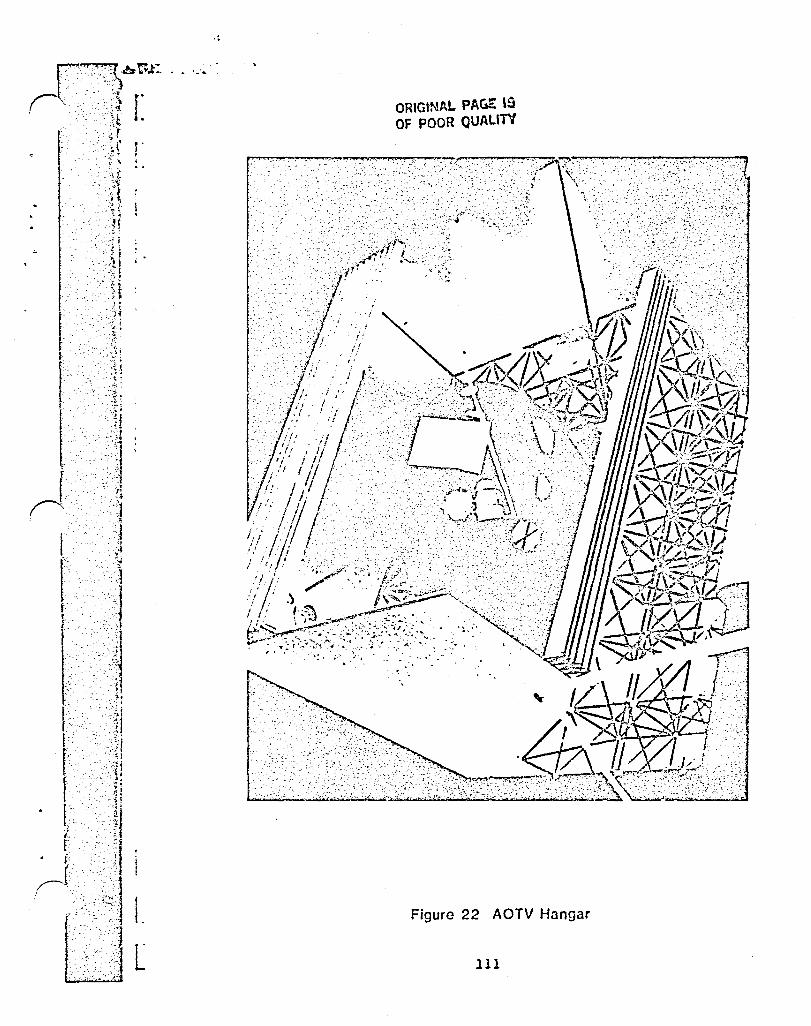
[
r I ~.
ORIGlNAl.. PAGl:: '5 OF POOR QUALITV
,'j,:,;','?'? \: .. ... .. ........... . ··'1 r' _'
Figura 22 AOTV Hangar
III
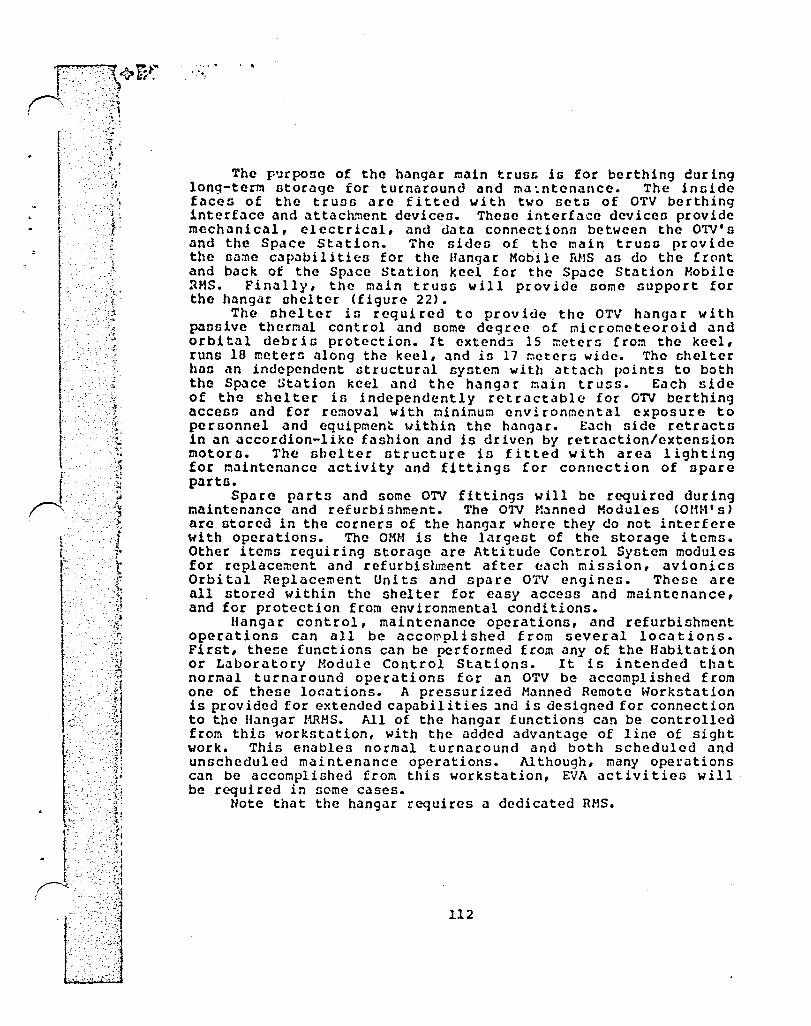
j.
rl···
·- . 0. ~;
, ' , . t-
. : ..
The p~rpose of the h~ngar main truss is for berthing euring long-term Dtorage for turnaround and rna ~ntenance. The inside f~cen of the trUOG arc fitted with two sets of OTV berthing interface and attachment deviceo. Theile interfa·.:e deviceo provide mechanical, electrical, and data connectionn between the OTVIs and the Space Station. The sides of the rn~in truss provide the same capilbil Hies for the Hangar Hobile mls ~n do the ! rClnt and back of the Space Station keel for the Space Station Mobile ~MS. Finally, the main trusn will provide some support for the hangar shelter (figure 22).
The shelter in required to provide the OTV hangar with passive thermal control and Dome degree of microt:1eteoroid and orbital debris protection. It extend3 15 ~ctern Crom the keel, runs 16 meters along the keel, and is 17 meters wide. The shelter hall ,'tn independent :;tructural system with ilttach points to both the Space ~t~tion keel and the hangclr !:lain truss. Each side of the ~helter is independently retractable Cor OTV berthing access and for removal with minimum environmental exposure to personnel clnd equipment within the h.lngar. E.lch sice retracts 1n an accordion-like fashion and is driven by rctrclction/extension motoro. The shelter structure is fitted with area lighting for m.lintenance activity and fittings for connection of spclre pllrts.
Spare pllrts clnd some OTV fittings will be required during maintenance and refurbishment. The O'IV Hanned Modules <om·!' 5)
arc stored in the corners of the hangar where they do not interfere with operations. The OliN is the largest of the storage items. Other items requiring storage are Attitude Control System modules for replacement and refurbisl~ent after ~ach mission, avionics Orbi till Replacement Uni ts and spare OTV engines. These are 1111 stored within the shelter for easy access and maintenance, and for protection from environmental conditions.
Hangar control, maintenance operations, and refurbishment operations can all be acco~plished from several locations. First, the~e functions can be performed from any of the Habitation or Laboratory Module Control Stations. It is intended that normal turnaround operations for an OTV be accomplished from one of these locations. A pressurized Manned Remote Workstation is provided for extended capabilities :lnd is deSigned for connection to the Hangar HlUlS. All of the hangar functions can be controlled from this workstation, with the added advant.lge of line of sight work. This enables normal turnaround and both scheduled and unscheduled maintenance operations. Although, many operations can be accomplished from this workstation, ~~A activities will be required in some cases.
Note that the hangar requires a dedicated RMS.
112

.' . '.~ I l .. ~-
" .. ~
"
. , ...•...... :'.~ I ,~". - :t:
r . ,·t I , ~ .
<J .' :: [.
'. -, .. . ~ " '
-, .... . '.
6.2 Propellant Storage and Trannfer
The S~ce Station must be able to ntore and transfer large quantities of cryogenic propellants to support ambitious lunar and planetary minsions. The lunar missionn discussed in previous nectiono require a Propellant Storage and Tranofer Facility. Our conceptual design for thin fncility consintn of two Orbital Storage Modules (OSH'n) and two Cryogenic Liquefaction and TranDfer Unito CCLTU's). The Oruital Storage Modules are brought to the Spac~ Station full and arc diopoGed of af ter uoe. On the other hand the CLTU'o arc pcrmanently attachcd to the Space Station and arc not din carded. 'I'hc CLTU aloo nerven ao the attacr_'nt:nt interface for the OSH.
The CLTU'n can tranofer propellants into and out of the Ol'V' o. During propellant loading the CLTU' s should be capabl e of a transfer rate of 5 metric tons per hour. This allows fueling of an 04 metric ton propellant stack, typical of a lunar GorHe, in an 18 hour period. Following OTV berthing, after misnion completion, the CLTU can off-load and liquify residual OTV propellants and return them to the Orbi tal Storage Hodules. The CLTU can both pnmp and liquify. The 1 iquifying system not only provides liquefaction for off-loaded, gaoeoua propellants but also cooling required to maintain the OSH at cryogenic ternperaturen. The CLTU liquefaction system provides this service only during periods of e~p05Ute to sunlight. A prel~minary design has n~t been performed on the CLTU, hO\~ever, several options are available for the liquefaction system. For example, a mechanical refrigeration system may be used. A mechanical refrigeration system would require 3.9 kw of electrical power for each CLTU. In addition, a corresponding load would be imposed on the Space Station heat rejection subsystem. Another option would be to use the hydride sorption refrigeration system currently under development at JPL. This system is likely to be more reliable as it requires no rotating equipment and in addition, only thermal energy is required to drive the compressor CRef. 19).
The Orbital Storage Module is dcnigncd to be launched within an unmanned shuttle derived launch vehicle with the payload positioned vertically above the external tank. The OSH has the capacity to store 100 metric tons of usable liquid hydrogen and liquid oxygen propellants. It contains one 23 metric ton hydrogen tank and one 85 metric ton oxygen tank e~ch covered by approximately 45 layers of MLI. For orbital injection the OSM is fitted with either a Trans-Stage Uppe~ Stage or an upper sta~e using existing Shuttle OMS engines. The OSH inert mass is approximately 12.4 metric tonG dry and is deorbited after use.
Figure 23 shows several tentative designs for this propellant storage module with the liquid hydrogen tanks fo~ward of the oxygen tank. The modules indicated in Figure 17 have the oxygen tanks forward. As shown in Figure 17, these modules are attached to the Space Station keel on the starboard side just above the keel extension.
113
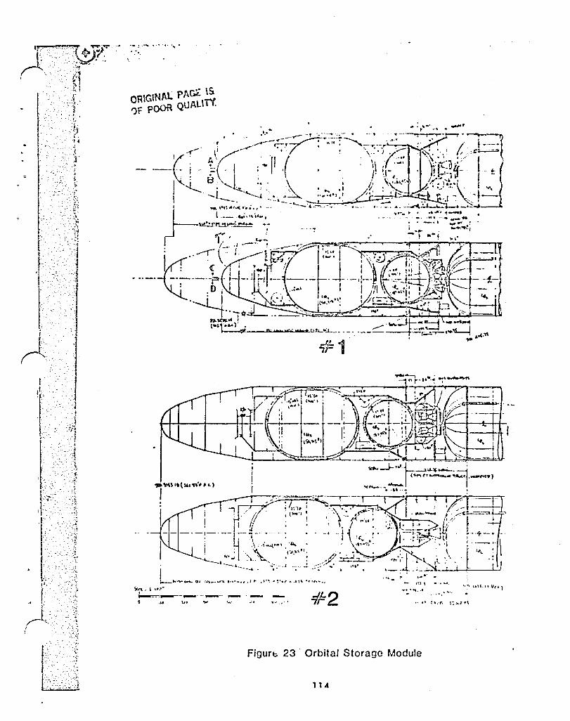
\.:
...
, -'-- ' .~
-._".i .. ..
, ,; .. "
.• !"- ...... "" •
.. ,"~.
y-:--~! -
I'~ I
~~L'"'''' I--=--c __ -_---._-. o .» lou ...... ,,,. ,"
Figurb 23
-IL2 7r .... ., ..... c
Orbital Storage Module
114
.t.· .. ··

r '. [.
~ . .
t .. ' .. ' ; ,::~j f'-' '-I
·r ., :'r:
.';"
r·· ;-.. ' . -.-~'~~ l
' c • .:-.~
.~ .. rt ;'!
A flight experiment regarding on-orbit hydrogen storage and transfer is currently in preparation at Lewis Rcnearch Center. This experiment, ncheduled for 1988, will trannfer 100 lb. of liquid hydrogen. The results of thin experi~ent arc likely to be a strong influence on the method3 of on-orbit cryogenic propellant ntorage and transfer.
115

, c-t· ,
','
--;j. -··r·
.: -+ . ,:,.:, .. :···~t
_. ·:··,)t-
~ - :- ~,:~~:~.~t .:.-.~ . ..=- ~.
, '~~' . ... - '>. , .. ~ , ;,~. '..;,:~,f
,.,. '"t: l' - .... "
)~~A:]t
6.3 Stacking Gantry
The OTV Stacking Gantry is a facility located on the lower keel just above the keel extension. This facility is used during normal flight preparation to mate payloads with OTV's and to mate OTV's when a two stage mission is in preparation.
Each gantry arm extends from the Space Station lower keel and attaches to the OTV at the front or back. The facility can handle two, two stage OTV otacks including the payloads. The two stacks will be held in parallel along the keel while being processed.
Propellant loading and off-loading is accomplished when the OTV is berthed at this facility.
In addition to proce~sing, the Stacking Gantry can provide ohort-term OTV storage in the event the OTV hangar is fully occupied. For protection against the space environment, a cover may be deployed over the underside of the OTV •
Figure 17 shows an OTV berthed in the Stacking Gantry and the Mars Sample Return mission spacecraft being mated to it.
116

. - .-' ~,~ ',,::.
", :}.: ~.-: . ' .. ' .
'. ·-.t,
6.4 Space Station Planetary Sample Quarantine Facility
Proposalu for the quarantine of samples returned by unmanned probes from Mars and other bodies in the solar system range from direct entry into the Earth's atmosphere (no quarantine in space), which has nome perfo~ance advantages, to a billiondollar mini-space station quarantine facility entirely Deparate from any other npace station. A middle ground option might une one modul e of the proposed NASA Space Station to serve as a quarantine facility for planetary samples in addition to other duties. This module would have its own life support system, but use Space Station power and thermal control. It would not be connected via any pressurized pathway to the rest of the station. In Figure 21 an OMV dcllve':'s a returned sample to thin single module.
The selection of overall approach to the quarantine problem i9 directly influenced by the real probability of returning some sort of replicating organism. A careful assessmcnt of this probability in light of recent da~a, and for thc comets and aoteroids as well as ~Iars and the Hoon is required prior to making thc final decioion and is beyond the scope of thin study. It nOh' appears hO\Y'ever, as though the probubility of finding life in returned samples is low. Some rink, however, docs exint and life that could exist in the temperature, prcssure, and radiation e~tremes of the Martian ourface or in the interior of a comet might be difficult to control. A degree of caution is therefore requirp.d. Reference 13 provides a preliminary deoign of a separate space station designed especially for sample quarantine that might be appropriate if the probability of finding life was thought to be significant. Figure 24 shows the whole facility and a weight statement. The power requirement of this configuration is estimated to be 25 to 35 kw (Ref. 13). Figure 25 shows the interior of the Laboratory Module for this design. Both figures were taken from reference 13.
A ncaled down, simplified version of the laboratory module in reference 13, attached structurally, but not e~vironmentally to the current NASA baseline Space Station, may be the most cost effective solution. This Quarantine Modulc w~uld be more of a way station than a major laboratory, though emergency equipment to isolate the module and one or more crewman for l0n9 periods of time would be available should the improbable occur. Figure 21 shows a conceptu~l Quarantine Module and its' mounting and operation on the NASA baseline space station.
117

~ ...... -....r -~ .... '~-'\o .• ...- .... OF' '[" • :.'.: R .' .... '~ "" .. ... • . __ . ' .'. :- •.. ,. .0:)1
0·"·····~1'
:- '. ".' :~ , .
":. . ;~: .
. '11 -'-"" . . -
.. .;..-.- .i~
. ;; .. , '>.
. _ ...... ----. ~ , ..
~IjV DELIVERS SAMPLE TO QUARANTINE MODULE
1.
2. 3.
4.
QUARANTINE MODULE 5.
O~W 6.
RETURNED PLANETARY SAMPLE 7.
AI RLoCK/OfljlJ HAP.D DOCK
FIGURE 21 LEGEND
118
OTHER MODULES OF GROI'lTH SPACE STh TI ON
MOB I LE RJ·1S
RADIATORS
ORIGINP.!.. P ,:J,-;": l~ OF POOR Qt.:f..LlT'i

..
/",
t1j ." ~,
._;'!.o <.:i
\1
. ,
Figure 21
0/' l~ ••.
OF PU01 0'" ;' .. ~" r ...... ,"\ ... I I.
119

~. f'\ r---<j .
{ :.:~ ",
, , " , .. "\. ~~.
;;j
~ , . ~,
tiAA!' A' I(-... WOOOVII
Orbiting Q . (f
uarantme Facility rom Ref. 13)
t~"M ... n:n M ... ·iS • CO"U'O!'L,"rs OF TIn: OQF
Figure 24
120
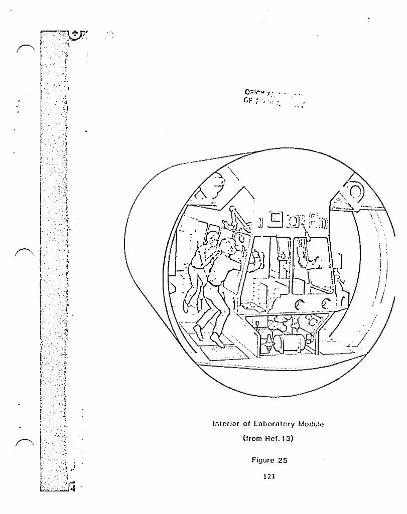
. '.
(.F :::.', '.,' , . . . '. -, - ....
f"\
Interior of Laboratory Module
, -','!~ .. }! ~ - ~ .," j.: (trom Ref. 13)
. ··t·
Figure 25
121
: , I '
\ ; I :
I I f J J ' I ! I I I !
;' I :

A otandllrd, 11 r."Icter (36 tt) long r.lodule, fluch 110 10 currently envisioned for the Life Sclcnceu L.1borl1tory in recent UI\SA Sp~ce Stl1tion studiefl (reL 113) in the beot rcodel .'1v..lill1blc. Tho Life Sciencca L.'1b, chown in figure 26 (\.:<lken fcor.! ref. 18), unoo approxir.liltely 25 Yow of electric.l1 power, requiren 30 kv of hC..lt rejection, and han II volur.le of 3,704 cubic feet. I\n cnvicioncd In reference 18, thin r.lodulc hlll; <tn intcrnlll ·O.:1(e haven" thllt w111 oupport two men (or twenty-two d.lYo, luoilltcd from the reot of the &tation. Tho fin~l dc~ign of the QU.lrantinc Dod'llo would probably not requl co 1l:J r.luch continuouc power and hCllt rcjt'ction .'1:1 the Life Sciencen l.ab, vhich h.lo l\ oellied anir::111 rCGcclrch llrea with ito' o ... n cnviron::'lcntal control llnd life nupport c~'ntcm (ECLSS). If the final con! igur..ltion includcn juct 11 large glove box, and an independent ECLSS capilblc of nupporting t~o indlvldualo for never.ll monthn under cccrgency conditions, the power requirement might go dovn ~n lo~ ~n 5 kv.
Individunl r~di~tor~ on e~ch ~odule arc now planned, with a ·ther~~l bun", utilng a:n.:1'IOnill aG the workln9 fluid, interconnecting all the module!>. Though inolation ot environ=ental and life support functions tHiy be required, the Quacclntine module could prObably still be 11nr.cd to the other ~odulen with the ar:.onia thermal bus, and the electric~l powf!r "1Od dolt,) lines.
The Quarantine Module would be denigned to acco~~odatc auto~ated docking of the O~ carrying the s3!':lple to ~n airlock attached to ~ glove box. Upon arrivoJl of .J s<ll"'ple, a biologist would u~c the glove box to re!':love a s!':lclll na~ple that would thon be examined quickly for any oigns of life. or ·stcrili:cd· by some means and sent to Earth. The main sample would be sealed in a ·super box", with the desired environmental control to await conclusions from the small sample. Given no signs of life or other dangers in the small sample, the main sample could then be shipped to Earth [or further exa~inatlon in a laboratory sitlilar the Center for Disease Control (CDC) high-hazard contair.;nent facility. Anothcr r.lcthod for dealing with the satlple would be to seal the entire sample in a ·super box· upon arrival at the Quarantine Module and ship it to E~rth in this secure container to be examined in a CDC type facility.
The ·super box· would be a rugged container capable of withstanding a Shuttle crash without rupture. Thernal control for the sample would be required. A Mara samplc might r£~uire maintenanc~ of -40 degrees C. Reference 14 indicates passive thermal control (insulation) can be used to keep the Mars sample cold while in Earth orbit. 1\ comet nucleus sample might be kept at a temperature as low as 100 degrees Kelvin (-173 degrees C).
122
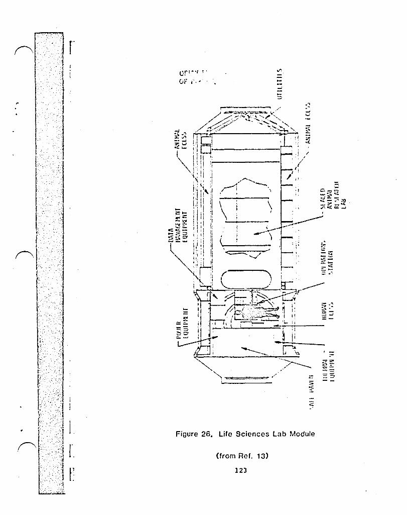
O!,,:-'l !'
or .-. ~ <. ---:::
Figure 26. Life Sciences Lab Module
(from Ref. 13)
123

, ~r:'_
--A . - -~ ~
'r". -'" . ",:~} -),
>
-":;. "
.z·-
"-- -~-
--).
-.':. ", - - ':.~: .. -;i~"
f' f~~~~j;lj
. '.
The impact to the Space Station would therefore conoint of accor.~od3ting one module designed for oample reception and quarantine. Duc to ita phynical iaolation from the reot of the Station it rni,)ht not be of much use foc other tanka. EVA woul d be rcqui red to enter it. The rcqui rcr=:cnt to nuntai none or more individuals in emergency iaolation for long periodn rnight make the Quarantine Module u!leful a3 a backup syntem or lifeboat, or 010 part of the ntation medical facilities. A nick individual could be effectively quarilntined. Prcvioions could !lloo be matlc to attilch it Viol a preG6urizcd paooagewily to the rent of the ntation during the expected long periodn between nample h~ndling ilod required quarantine. Thin would significantly incre~se ito utility.
The Hara nample will be either acrobraked or propulnively innected into lew Ellrth orbit with Golid rockets. Hare launch will be timed to place ~he sample in the Space Station plane at the time of rcndczvou~. Referenceo 14 and 15 ouggcst a 870 km (470 1'\::1) ci rcular orbl t ao the 1: inoll dentinatic.n. Reference 16 indicateo the OHV can easily retrieve the entire 63.6 kg <140 lb) Ea rth orbi t Capsul e from orbi tal al ti tudes ao high olG 2,777 krn (1,500 nm) circular, or can lsccommodoltc retrievcll with ~ s~~ll plane chnnge from lower altitudes.
The Kopif and Ceres sample return mis~ion3 both aerobrake into LEO. Refcr~nce 5 suggests the aerobraked samples cnn be circularize~ at 370 km (200nm) in the Space Station plane if desired. Recent Sp.Jce Station designs use a 463 km (250) to 500 km (270 ~~) :ltitudc. The samples could also be aerobraked olnd circular ized into 870 km (470 nm) in-plane orbi ts as wi th the Hars Sample return Vehicle. Only the 93 kg (205 lb) Eclrth Orbit Capsules ar~ aerobraked into Earth orbit. The Mariner Hark II opacecraft also return to the vicinity of Earth but fly by after releasing their Earth Orbit capsules.
6.5 OTV Maintenance and Refurbishment Operations
OTV maintenance and refurbishment operations at the Space Station consist of several classifications of work. These include Normal Turnaround, Scheduled and Unscheduled Maintenance and Refurbishment, and Secondary Support Activities. Table 7 lists the Space Station crew manhour reqUirements for these activities as they relate to Planetary missions. The classifications mentioned above have become somewhat mixed in this table as each mission has been charged with prorated shares of the manhour rcquire~ents for scheduled maintenance operations.
Normal OTIJ turnaround is def ined as the operations sur rounding cheCKout, integration, and launch and retrieval. This is distinct from l:Iaintenance operations which can be either scheduled preventive maintenance or unscheduled repair of faulty components. Table 7 lists four separate operations which are clas5ified as Hormal turnaround operations. These are as follows:
o OTV Refurbishment
124

.' .:".;
" '\::'·1 . '.'
L:
. i
( ;. ': ~ ::1 i.
. r·' ... : r . , r -
o OTV/Payload Integration and Checkout o Fuel, Release and Launch o Rendezvouo and Retrieve OTV using OMV
OTV re!urbiohrnent includes the normal turnaround or~ration. of visual inoycction, removal and replaccment of ACS modules and a uyntem tcot. Also, part of the rnanhours required fo; ocheduled mainter.ance han been charged to each miooion. II io assumed th.Jt Dchcduled maintenance will be performed on al OTV after five minsiono. necause of this, one fifth of th( manhcur rcquirpmcnts have becn included. Normal turnaroun( requireD two ere..., meml'era for execution while somo of the maintenzlnc( operations rcqui re four. For a Single stage' OTV niooion, thh operations phase requires approximatrly 52 manhouro, half of which are th. result of maintenance vork.
orl to ~ylo~d integration and checkout involveD the tranofer of the OTV from the hangar to chc stacking facility, the transfer of the payload from its holding location to the otacking facility, the ~ating of the OTV and the payload, and finally the integrated system teot. This phase includeo only normal turnaround opcrationo and no rnaintenance operations. The integrl1ted teat is anticipated to be accomplished with ON and payload oclf teot ca~bl1itieo and will conoequently not rcqui re a significant nU!:lber of rlanhourD. Thia operational phase requireD two crew mem~erD and approxioately 11 ennhours.
The fuel, release and launch phase includeD ON fueling, release fro~ the stacking g~ntry, tranafer by the Space Station RUS to the launch location, mating with the mw, and launch. This pha~e also includes only normal OTV turnaround operations and requires two crew members. The manhour requirements for a one stage mission ~re approximately 24 manhours, while a two stage mission requires about 36 manhourD. The two stage mission does not require twice the crew manhourD since prelaunch and launch operations are not performed twice for the mission while the fueling operations are.
Rendezvous and retrieval operations involve deployment of the OMV, rendezvous of the OMV and OTV, berthing, and safing of the OTV. Again, this phase includes only normal operations. Two crew members are required and a total of about 12 manhours will be expended.
Table 7 also lists variouD Secondary Support Activities and appro~irndte manhour requirements for ~ach. The removal of an aer~brake has been included for missions that have an expended orv. Shuttle rendezvous and payload rcmoval reprcsents the del ivery of a mission pay load or pI anetary spacecr af t. ULV propellant delivery involves the arrival and replacement of one of the Orbital Storage Modules. The manhour requi rements given for the propellant operations are prorated to the amount of propellant used for each mission. The sample retrieval operations if,sted apply only to the three sample return rnissiono listed.
In addition to normal turnaround operations and secondary Dupport activities, maintenance operations are included, as
125

. "
" ". "."'.
discuaGed previously, in Table 7. OTV maintenance can be divided into three basic levels. Level I maintenance involves both scheduled and unscheduled functionn that take place on the vehicle ao it in berthed in the Space Station sheltered maintenance facility. Level 2 maintenance is repair of replaceable ON parts at the Space Station or on Earth if test equipment, opares availnbllity, nnd economic constraints dictate. Level 3 maintenance includes Earth based repair of 01V components. For the purposes of this ntudy, only Level I ncheduled maintenance is considered.
Two specific op~rationD are included in OTV refurbishment. The first io the removal and replacement of a fuel cell and battery. 'Ihis operation requireD t\iO crew mC!:lbecn and approximately 5 manhouro. Second in the removal and replacement of two OTV engines. This operation requireD four crew memberD working a total of 65 hours per engine. It is mont likely that EVA activity will be required for these unscheduled operations.
TheDe manhour and operations requirements were derived from reference 20. This reference aloo provides additional details on scheduled and unscheduled maintenance operations, and initial delivery operationo.
126
7.0 Conclusions and Recommendations
An Operational Space Station with large high energy (cryogenic propellant) orbital transfer vehicles can support an extremely wide range of space transportation options. The following conclusions and rccomlnendations outline somc of the areas requiring significant additional study:
1) The Space Station must include a cryogenic propellant depot with large scale (hUndreds of oetric tons) on-orbit propellar.t transfer capabili ty. This in central to any large space trannportation operations. The abil ity to trannfer and Dtore cryogcl'ic propellants in theoe quantities must be developed.
2) The OTV vehicles must be ·stackable· to provide multistage capability. With this capability a larger payload or a high delta V can always be accommodated by adding another propuloion stage (although eventually this becomes impractical). Without this capability, the systcm is constrained to the performance cnvelope of a single OTV.
3) For practical high density round trip operation to LUnar Orbit (and Geosynchronous orbits) acrobraking is required of the OTV's. Dcvelo~ent of aerobraking technology should be undertaken.
4) In order to support the high flight rate lunar program a large shuttle derived-unmanned launch vehicle with payload in the 100 metric ton class should be developed as a cryogenic propellant tanker vehicle. Such a vehicle would reduce the average launch rate for lunar support from 25 shuttle launches a year (one every two weeks) to 10 a year (one every 5 weeks). The average annual savings in launch costs alone should be around 1.4 billion dollars, enough to recover development costs in the first two years.
5) The External Tank, Aft-Cargo Compartment proposed by Marshall Space Flight Center for use on shuttle launches should be developed for carrying the Expendable Lunar Lander. With at least 16 launches required in the first four years of heavy lunar traffic, this could also be easily amortized.
6) tor lunar base support, the Space Station must be capable of substantial operational support such as flight control, storage and prepa(ation of payloads and mission stacks, propellant tra!'.sfer operations, and routine OTV cheCKout and maintenance. This meano
127
....
-: ., - ~.
the baoic Space Station operationo will be shifted toward support of trannportation. This will require some enlargement of the Space St~tion.
This emphasio, however, does Wlt preclude heavy uti! ization of the Space Station aa a acientific research and facilities base. Even with the lunar base, large traffic arrivals or departures only occur appro~imately once every two weeks.
7) Interplanetary depa~ture from lunar orbit using only lunar derived O? for propellant docs ~ appear to be oignificantlj advantageous as long ao all lunar fuel (11 2) must be brought from Earth. tl.o advantage wan found if the total outbound cargo must come from Earth. The case using lunar derived fuel, aD well as lunar oxygen should be studied.
8) The economics of lunar surface to lunar orbit .~erry operationo with a reusable lander should be studied to determine approximately what it costa to fly ouch a mission with and without lunar produced propellants. This coot number is nceded to aoseoo :he economics of a number of schemeo using lunar reoources. The general economico of a round-trip two-stage OTV sortie from LEO to lunar orbit aloo needs to be determined.
9) Any exploration, research, or engineering cevelopment that might result in a source of lunar hydrogen should be pursued.
10) The rcqui rements that manned Mars, Mars moon, or asteroid missions would impose on the Space Station snould be de te rmi ned. Rumor s of Russian ef forts exi st. Such a program might occur sometime during the Space Station's lifetime.
11) The design of and rationale for the Quarantine Module require more definition. A sample return mission is quite likely to occur during the lifetime of the Space Station and the IOC design should take this into account. As a part of this effort, special attention needs to be paid to the sample return container, particular ly its env i ronmental control system and packaging for Earth return.
128
8.0 Definitions of Terms and Acronyms
Aerobrake
CLTU
De-lta V
E-Ascent
ECLSS
E-Lander
EOC
ERV
ET
ET-ACC
Free Return Trajectory
Geosynchronous Orbit
9 losses
Iap
JSC
LEO
LH2
LLMM
LOI
LOSS
The portion of a stage that creates drag when the atmosphere is used to slew the stage down
Cryogenic Liquefaction and Transfer Unit
Change in velocity required
Expendable Ascent Stage, propulsion stage to return personnel from lunar surface
Environment~l Control and Life Support System
Expendable Lander, large one way lunar lander
Earth Orbit Capsule
Earth Return Vehicle
External Tank
External Tank - Aft Cargo Compartment
Earth to Moon orbit that loops around the moon and returns to earth without any rOCKet firings
An equatorial orbit at the altitude (35,810 km) at which the satellites revolution and the earth's rotation are the same so the satellite appears to remain stationary over fixed point on the earth
Difference between theoretical and actual space maneuver requirements due to altitude changes during the time the rocket is firin~
Specific impulse - measure of engine performance
Johnson Space Center
Low Earth Orbit
Liquid Hydrogen
Lunar Landing Manned Module - to be carried on E-Lander and E-Ascent
Lunar Orbit Injection
Lunar Orbit Service Station
129

.... " "'", '" ....
.... '. - '- .. :.~?
LOX
MABM
HLM
loiRV
OMM
OIN
OSH
OTV
PL
PLaero
R-LEH
R-LLEl-t
SCA
TLl
T/W
ULV
Wp
Liquid Oxygen
Mars Ascent Booot Module
Mars Lander Module
Mars Rendezvous Vehicle
OTV manned :nodul e - manned n.odul e to be rna ted to OTV Orbit Maneuvering Vehicle
Orbital Storage Module
Orbit Transfer Vehicle
Payload
Payload carried through an aerobrake maneuver
Reusable Lunar Excursion Module - single stage lunar lander/launch vehicle - reusable
Reusable Lunar Landing Manned Module
Sample Canister Assembly
Trans-Lunar Injection
Thrust to weight ratio
Unmanned Launch Vehicle
Propellant weight (capacity of a stage)
130
~ •.• k.···· o
f'.: f-:
.F· , ~~" ..
r:"
, :\~
. ~.:
. -;-: ~
j.
9.0 References
1. Lunar Surface Return Report - In-house JSC study, presente March 1984.
2. Roberts, Barney B., OTV rleight Estimates, JSC Memorandu ET4/8401-11 L.
3. Apollo 11 Minnion Report, prepared by the Mission Evaluatio Team, NASA Report No. N71-25042.
4. Bourke, Blanchard, and DeVriea, Mars Sample Return Mission FY 84 Study Report to OSSA, 'JSC and JPL, July 26, 1984
s. Bourke, Friedlander, DeVries, Norton, and Blanchard, Co~plet Report, Advanced Planetary Studies, Mars Sample Return Quarterly Review, FY 1984, May 15, 1984.
6. Friedlander, Soldner, and Niehoff, Performance Assessmen of Planetary t1issions as Launched f rom an Orbi ting Spac Station, Science Applications, Inc. Report No. SAl 1-120 340-T19, September, 1982.
7. Planetary Exploration Through Year 2000, A Core Program Executive Summary, Part One of a repnrt by the Solar Syste Exploration Committee of the NASA Advisory Council, Gov. Print· ing Office, Washington D.C., 1983.
a. ~omet Nucl eus Sampl. e Return Mission, Science Appl ication. Report No. 83/1152, Presentation to Solar System Exploratiol Committee Summer Study, Snowmass, Colorado, August 2, 1983.
9. Draper, R. F., The Mariner Hark II Program, AlAA-84-0214 presented at the AlAA 22nd Aerospace Sciences Meeting January 9-12, 19B4/Reno, Nevada.
10. Private communication from John Soldner, SAl.
11. Swenson, Hascy, and Edsinger, A New Sytitem Concept fOI a Titan Atmospheric Probe, NASA Ames, AlA!\-84-04 56, AIf~i 22nd Aerospace Sciences Meeting, January 9-12, Reno, Nevada.
12. Calendar of Planetary Mission Opportunities, SAl
13. DeVincenzi, Donald L., Bagby, John R., Orbiting Quarantin( Facili ty, NASA SP-454, NASA Scientific and Technical lnformatior Branch, Washington, D. C., 1981.
14. Presenta tl on Package from Joi nt JSC-JPL-SAl Meeting or Mars Sample Return, Mcrch 27, 1984.
131
"
, "
15. Bourke, R. D., Blanchard, D., and DeVries, J. P., Hars Sample Retu~n Minnion (Presentation Hateriai..>, FY 84 Study Report to OSSA, JPL D-1690, July 26, 1904.
16.
17.
Teleoperator Maneuvering System ~tudy, Mission Requirements and System Definition, Study l1eview, Prp.pared by Vought Corp. for the NASA Marshall S}ace Flight Center, December 16, 1982.
~omet Nucleus Sample Return with Aerocapture, Presentation Package, no date, Science Applications Inc.
18. Space Station Reference Configuratio~ Description, Systems Engineering and Integration, Space Sta~ion Program Office, JSC-19989, NASA Johnson Space Center, Houston, Texas, AUgU3t, 1984.
19. Advanced Thermal Control Technology for Cryogenic Propellant Storage, NASA-OAST Final Report F.Y., Gail Klein, 1983.
20. Definition of Technology Development Minsions for Early Space Station's Orbit Transfer Vehicle Servicing. Phase III, Tas.; 1 Space Station. Support of Operational O'l:V Servicing, Contract No. NAS8-3S039, General Dynamics, December 1983, Report No. GDC-SP-83-067.
132
/

End of Document


![A Reproduced Copy - NASA · skylab rescue spacevehicle countdown. ths tcp contawsi - hazardous operathiis . nasa concurrence/approval. tes inegr tion branch (la-pln-1] man sr te s](https://static.fdocuments.us/doc/165x107/5e55deef0501c72bd41098e2/a-reproduced-copy-nasa-skylab-rescue-spacevehicle-countdown-ths-tcp-contawsi.jpg)