A REPORT TO 1361605 ONTARIO LTD. A SOIL INVESTIGATION …
39
A REPORT TO 1361605 ONTARIO LTD. A SOIL INVESTIGATION FOR PROPOSED RESIDENTIAL DEVELOPMENT 13576 AND 13584 COLERAINE DRIVE TOWN OF BOLTON Reference No. 1006-S045 MAY 2013 DISTRIBUTION 4 Copies - Calder Engineering Ltd. 1 Copy - Soil Engineers Ltd. (Toronto) 1 Copy - Soil Engineers Ltd. (Newmarket)
Transcript of A REPORT TO 1361605 ONTARIO LTD. A SOIL INVESTIGATION …

A REPORT TO 1361605 ONTARIO LTD.
A SOIL INVESTIGATION FOR PROPOSED
RESIDENTIAL DEVELOPMENT
13576 AND 13584 COLERAINE DRIVE
TOWN OF BOLTON
Reference No. 1006-S045
MAY 2013 DISTRIBUTION 4 Copies - Calder Engineering Ltd. 1 Copy - Soil Engineers Ltd. (Toronto) 1 Copy - Soil Engineers Ltd. (Newmarket)

Reference No. 1006-S045 ii
TABLE OF CONTENTS
1.0 INTRODUCTION .................................................................................... 1
2.0 SITE AND PROJECT DESCRIPTION .................................................. 2
3.0 FIELD WORK .......................................................................................... 3
4.0 SUBSURFACE CONDITIONS .............................................................. 4
4.1 Topsoil and Topsoil Fill .............................................................. 4 4.2 Earth Fill ...................................................................................... 5 4.3 Silty Clay Till .............................................................................. 6 4.4 Compaction Characteristics of the Revealed Soils .................... 8
5.0 GROUNDWATER CONDITIONS ......................................................... 11
6.0 DISCUSSION AND RECOMMENDATIONS ...................................... 13
6.1 Foundations ................................................................................. 15 6.2 Engineered Fill ............................................................................ 17 6.3 Underground Services................................................................. 20 6.4 Backfilling in Trenches and Excavated Areas ........................... 21 6.5 Garages, Driveways and Landscaping ....................................... 23 6.6 Pavement Design ........................................................................ 24 6.7 Soil Parameters ........................................................................... 25 6.8 Excavation ................................................................................... 26
7.0 LIMITATIONS OF REPORT ................................................................. 28
Reference No. 1006-S045 iii
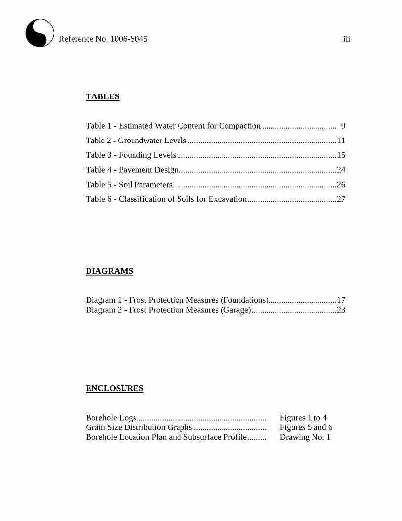
TABLES
Table 1 - Estimated Water Content for Compaction ................................... 9
Table 2 - Groundwater Levels ...................................................................... 11
Table 3 - Founding Levels ........................................................................... 15
Table 4 - Pavement Design .......................................................................... 24
Table 5 - Soil Parameters ............................................................................. 26
Table 6 - Classification of Soils for Excavation .......................................... 27
DIAGRAMS Diagram 1 - Frost Protection Measures (Foundations)................................ 17 Diagram 2 - Frost Protection Measures (Garage) ........................................ 23 ENCLOSURES Borehole Logs ............................................................. Figures 1 to 4 Grain Size Distribution Graphs .................................. Figures 5 and 6 Borehole Location Plan and Subsurface Profile ......... Drawing No. 1

Reference No. 1006-S045 1
1.0 INTRODUCTION
In accordance with instructions from Mr. Ted Minor, P.Eng., Project Manager, of
Calder Engineering Ltd., and written authorization dated June 5, 2010, from
Mr. Peter Halmos of 1361605 Ontario Ltd., a soil investigation was carried out at a
parcel of land which is the east half of Lot 8, Concession 5 and Part of Block 307,
Registered Plan 43M-1324 in the Town of Bolton, for a proposed Residential
Development.
The purpose of the investigation was to reveal the subsurface conditions and to
determine the engineering properties of the disclosed soils for the design and
construction of the proposed project.
The findings and resulting geotechnical recommendations are presented in this
Report.

Reference No. 1006-S045 2
2.0 SITE AND PROJECT DESCRIPTION
The site is situated on Halton-Peel till plain where drift dominates the soil
stratigraphy. In places, the drift has been modified by the water action of the glacial
lake known as Peel Ponding and filled with lacustrine clay, silt, sand and/or
reworked till.
The subject site is located east of Jack Kenny Court, west of Coleraine Drive and
north of Grapevine Road in the Town of Bolton. The investigated area is located in
the backyard of the existing residences. The site is generally grass-covered with
part of the site being wooded.
The site is bounded on the east side by the properties at 13576 and 13584 Coleraine
Drive and on the north, south and west by a residential subdivision.
It is understood that the proposed project will consist of a residential development,
and will be provided with municipal services and roadways meeting urban
standards.

Reference No. 1006-S045 3
3.0 FIELD WORK
The field work, consisting of 4 boreholes to a depth of 6.6 m, was performed on
June 22 and 23, 2010, at the locations shown on the Borehole Location Plan and
Subsurface Profile, Drawing No. 1.
The holes were advanced at intervals to the sampling depths by a track-mounted,
continuous-flight power-auger machine equipped for soil sampling. Standard
Penetration tests, using the procedures described on the enclosed “List of
Abbreviations and Terms”, were performed at the sampling depths. The test results
are recorded as the Standard Penetration Resistance (or ‘N’ values) of the subsoil.
The relative density of the granular strata and the consistency of the cohesive strata
are inferred from the ‘N’ values. Split-spoon samples were recovered for soil
classification and laboratory testing.
The field work was supervised and the findings recorded by a Geotechnical
Technician.
The elevation at each of the borehole locations was determined with reference to the
site bench mark shown on Drawing No. 1, which is the top of the back door sill of
the property at 13576 Coleraine Drive. It has been given an assumed elevation of
100.00 m.

Reference No. 1006-S045 4
4.0 SUBSURFACE CONDITIONS
Detailed descriptions of the encountered subsurface conditions are presented on the
Borehole Logs, comprising Figures 1 to 4, inclusive. The revealed stratigraphy is
plotted on the subsurface profile on Drawing No. 1, and the engineering properties
of the disclosed soils are discussed herein.
The investigation has disclosed that beneath a topsoil veneer or, in 3 locations, a
layer of topsoil fill and earth fill, the site is underlain by a stratum of silty clay till.
4.1 Topsoil (Borehole 4) and Topsoil Fill (Boreholes 1, 2 and 3)
The topsoil and topsoil fill are 4 cm and 15 cm thick. They are dark brown in
colour, indicating they contain appreciable amounts of roots and humus. These
materials are unstable and compressible under loads; therefore, the topsoil and
topsoil fill are considered to be void of engineering value. Due to their humus
content, they may produce volatile gases and may generate an offensive odour under
anaerobic conditions. Therefore, they must not be buried within the building
envelope or deeper than 1.2 m below the finished grade so they will not adversely
impact the environmental well-being of the developed areas.
Since the topsoil and topsoil fill are considered void of engineering value, they can
only be used for general landscaping and landscape contouring purposes. Fertility
analyses can determine their suitability as planting material.

Reference No. 1006-S045 5
4.2 Earth Fill (Boreholes 1, 2 and 3) A layer of earth fill was encountered in 3 of the 4 boreholes and was found
extending to depths ranging from 1.5 to 3.0 m below the prevailing ground surface.
It is amorphous in structure and consists predominantly of silty clay with variable
amounts of gravel and occasional topsoil inclusions.
The original topsoil was detected beneath the earth fill in Borehole 3 at a depth of 2.0+ m below the prevailing ground surface, and may have been obscured by the augering in the remaining boreholes.
The water content of the samples was determined, and the results are plotted on the
Borehole Logs; the values range from 15% to 36%, with a median of 22%,
indicating that the fill is in a moist to wet, generally wet condition. The high water
content values are likely due to the concentrated topsoil inclusions in the fill.
The obtained ‘N’ values range from 6 to 44, with a median of 10 blows per 30 cm
of penetration. This shows that the fill has generally self-consolidated. The high
‘N’ value of 44 is probably due to the presence of gravel and wood, plant and other
debris found in the fill.
The earth fill likely originates from vicinal construction, contains topsoil inclusions
and other deleterious material, and its density is non-uniform; therefore, it is
unsuitable for supporting structures. In using the fill for structural backfill, or in
pavement and slab construction, it should be subexcavated, inspected, sorted free of
topsoil inclusions and any deleterious material, and properly recompacted.
A grain size analysis was performed on 1 representative sample of the earth fill; the
result is plotted on Figure 5.

Reference No. 1006-S045 6
As noted, the fill is amorphous in structure; it will ravel and is susceptible to sudden
collapse in steep cuts, particularly if it is in a wet condition. Where the earth fill is
free of deleterious materials, its engineering properties are generally similar to those
of the silty clay till, described in the following section.
One must be aware that the samples retrieved from boreholes 10 cm in diameter
may not be truly representative of the geotechnical and environmental quality of the
fill, and do not indicate whether the topsoil beneath the earth fill was completely
stripped. This should be further assessed by laboratory testing and/or test pits.
4.3 Silty Clay Till (All Boreholes)
The clay till is the predominant soil on the property and it extends to at least the
maximum investigated depth in all boreholes. The particle sizes range from clay to
gravel, with the clay fraction exerting the dominant influence on the soil properties.
Occasional sand and silt seams and layers were detected in the clay till mantle. The
till is heterogeneous in structure, indicating it is a glacial deposit.
Sample examinations show that fissures permeate the upper layer of the till within a
depth of 0.8± m from the prevailing ground surface in the vicinity of Borehole 4,
becoming less prevalent with depth. This shows that the upper layer has been
fractured by the weathering process.
Hard resistance was encountered during augering, showing that the clay till is
embedded with occasional cobbles and boulders.

Reference No. 1006-S045 7
The obtained ‘N’ values range from 12 to 64, with a median of 32, indicating that the consistency of the clay till is stiff to hard, being generally very stiff. In places, the obtained ‘N’ values decrease with depth where the soil colour changes from brown to grey. This indicates that in these areas, the till has been reworked by the water action of the glacial lake; above the reworked till, a harder soil layer has been formed by soil desiccation. The Atterberg Limits of 4 representative samples and the natural water content of all the samples were determined; the results are plotted on the Borehole Logs and summarized below: Liquid Limit 29%, 31%, 32% and 33% Plastic Limit 17%, 18% and 19% Natural Water Content 12% to 21% (median 15%) The results show that the clay till is a cohesive material with low to medium plasticity. The natural water content generally lies below its plastic limit, confirming the consistency as determined from the ‘N’ values. Grain size analyses were performed on 4 representative samples of the clay till. The results are plotted on Figure 6. The deduced engineering properties related to the project are as follows:
• Moderate frost susceptibility and soil-adfreezing potential.
• Low water erodibility.
• Low permeability, with an estimated coefficient of permeability of
10-7 cm/sec, and runoff coefficients of:

Reference No. 1006-S045 8
Slope
0% - 2% 0.15
2% - 6% 0.20
6%+ 0.28
• A cohesive soil, its shear strength is primarily derived from consistency
which is inversely related to its moisture content. It contains sand; therefore,
its shear strength is augmented by internal friction.
• It will generally be stable in a relatively steep cut; however, prolonged
exposure will allow the fissures in the weathered zone and the wet sand and
silt seams and layers to become saturated, which may lead to localized
sloughing.
• A poor pavement-supportive material, with an estimated California Bearing
Ratio (CBR) value of 3%.
• Moderate corrosivity to buried metal, with an estimated electrical resistivity
of 4000 ohm·cm.
4.4 Compaction Characteristics of the Revealed Soils
The obtainable degree of compaction is primarily dependent on the soil moisture
and, to a lesser extent, on the type of compactor used and the effort applied.
As a general guide, the typical water content values of the revealed soils for
Standard Proctor compaction are presented in Table 1.

Reference No. 1006-S045 9
Table 1 - Estimated Water Content for Compaction
Water Content (%) for Standard Proctor Compaction
Soil Type
Determined Natural Water Content (%)
100% (optimum)
Range for 95% or +
Earth Fill 15 to 36 (median 22)
17 13 to 22
Silty Clay Till 12 to 21 (median 15)
17 and 18 14 to 23
Based on the above findings, the silty clay till is generally suitable for a 95% or +
Standard Proctor compaction. The majority of the earth fill is either too wet or on
the wet side of the optimum and will require aeration or mixing with drier soils
prior to structural compaction. The aeration can be effectively carried out by
spreading the fill thinly on the ground in dry, warm weather.
The earth fill must be sorted free of concentrated topsoil inclusions and other
deleterious materials prior to structural use.
The earth fill and silty clay till should be compacted using a heavy-weight,
kneading-type roller. The lifts for compaction should be limited to 20 cm, or to a
suitable thickness as assessed by test strips performed by the equipment which will
be used at the time of construction.
When compacting the very stiff to hard silty clay till on the dry side of the optimum,
the compactive energy will frequently bridge over the chunks in the soil and be
transmitted laterally into the soil mantle. Therefore, the lifts of this soil must be
limited to 20 cm or less (before compaction). It is difficult to monitor the lifts of
backfill placed in deep trenches; therefore, it is preferable that the compaction of

Reference No. 1006-S045 10
backfill at depths over 1.0 m below the road subgrade be carried out on the wet side
of the optimum. This would allow a wider latitude of lift thickness. Wetting of the
sound till will be necessary to achieve this requirement.
If the compaction of the soils is carried out with the water content within the range
for 95% Standard Proctor dry density but on the wet side of the optimum, the
surface of the compacted soil mantle will roll under the dynamic compactive load.
This is unsuitable for road construction since each component of the pavement
structure is to be placed under dynamic conditions which will induce the rolling
action of the subgrade surface and cause structural failure of the new pavement.
The foundations or bedding of the sewer and slab-on-grade, on the other hand, will
be placed on a subgrade which will not be subjected to impact loads. Therefore, the
structurally compacted soil mantle with the water content on the wet side or dry side
of the optimum will provide an adequate subgrade for the construction.
The presence of boulders will prevent transmission of the compactive energy into
the underlying material to be compacted. If an appreciable amount of boulders over
15 cm in size is mixed with the material, it must either be sorted, or must not be
used for construction of engineered fill and/or structural backfill.

Reference No. 1006-S045 11
5.0 GROUNDWATER CONDITIONS Groundwater seepage encountered during augering was recorded on the field logs. The boreholes were checked for the presence of groundwater and/or the occurrence of cave-in upon their completion and the levels are plotted on the Borehole Logs. The data are plotted on the Borehole Logs and summarized in Table 2. Table 2 - Groundwater Levels
Borehole
Soil Colour Changes
Brown to Grey
Seepage Encountered
During Augering
Measured Groundwater/ Cave-in* Level On Completion
BH No. Depth (m) Depth (m) Depth (m) Amount Depth (m) El. (m)
1 6.6 4.5 - - Dry -
2 6.6 4.5 5.0 Slight 4.9 91.5
3 6.6 4.5 3.0 Moderate 3.0 93.1
4 6.6 4.5 - - Dry -
Groundwater and groundwater seepage were measured at depths of 3.0 m and
4.9± m below the prevailing ground surface (El. 93.1 m and El. 91.5± m) in 2 out of
the 4 boreholes. The relatively shallow groundwater level in Borehole 3 is likely
due to infiltrated precipitation trapped in the voids of the earth fill, rendering
perched groundwater at shallower depths, particularly in wet seasons.
The colour of the soil changes from brown to grey at a depth of 4.5 m below the
prevailing ground surface. This indicates that the upper soil has oxidized; the
groundwater regime of the site is inferred to occur in the saturated grey soils and
will fluctuate with the seasons.

Reference No. 1006-S045 12
The yield of groundwater from the silty clay till, due to its low permeability, will be
small and limited, and can be controlled by normal pumping from sumps.

Reference No. 1006-S045 13
6.0 DISCUSSION AND RECOMMENDATIONS
The investigation has disclosed that beneath a topsoil veneer or, in 3 locations, a
layer of topsoil fill and earth fill, the site is underlain predominantly by a stratum of
stiff to hard, generally very stiff silty clay till. The stiff silty clay till is restricted to
the weathered zone which extends to a depth of 0.8± m below the prevailing ground
surface in the vicinity of Borehole 4.
Groundwater was detected in 2 out of the 4 boreholes at depths of 3.0 m and 4.9 m
below the prevailing ground surface (El. 93.1 m and El. 91.5 m). The groundwater
regime of the site is inferred to lie in the saturated grey soils which occur at a depth
of 4.5 m below the prevailing ground surface, and will fluctuate with the seasons.
The groundwater yield from the encountered soil, due to its low permeability, will
be small and limited, and can be controlled by normal pumping from sumps.
The geotechnical findings within the investigated depth of 6.6± m which warrant
special consideration are presented below:
1. The topsoil and topsoil fill are highly compressible and must be stripped as
they are unsuitable for engineering applications. Due to their high humus
content, they will generate volatile gases under anaerobic conditions. For the
environmental as well as the geotechnical well-being of the future
development, the topsoil and topsoil fill should not be buried within the
building envelope, or deeper than 1.2 m below the exterior finished grade.
2. The earth fill found at the site extends to depths of 1.5 m, 2.3 m and 3.0 m
below the prevailing ground surface, and appears to be spoil from vicinal
construction. The density of the fill is non-uniform and consists of topsoil

Reference No. 1006-S045 14
inclusions and other deleterious material, rendering the fill unsuitable for
supporting foundations. For other structural use, the fill must be
subexcavated, inspected, assessed, sorted free of topsoil inclusions and
deleterious materials, aerated and properly compacted. If it is impractical to
sort the topsoil and other deleterious material from the fill, then the fill must
be wasted and replaced with properly compacted inorganic earth fill.
3. Due to the presence of topsoil, topsoil fill, earth fill and weathered soil, the
footing subgrade must be inspected by a geotechnical engineer, or a
geotechnical technician under the supervision of a geotechnical engineer, or
by a building inspector who has geotechnical experience, to assess its
suitability for bearing the designed foundations.
4. The sound natural soils are suitable for normal spread and strip footing
construction.
5. Earth fill will be required for the site grading. It is generally more
economical to place engineered fill for normal footing, sewer and road
construction.
6. Depending on the design grade of the basement, perimeter and floor
subdrains and dampproofing of the foundation walls will be required for the
basement construction. The subdrains should be shielded by a fabric filter to
prevent blockage by silting. This can be further assessed at the time of
basement excavation.
7. Excavation into the very stiff to hard silty clay till containing boulders may
require extra effort and the use of a heavy-duty backhoe. Boulders larger
than 15 cm in size are not suitable for structural backfill.
The recommendations appropriate for the project described in Section 2.0 are
presented herein. One must be aware that the subsurface conditions may vary
between boreholes. Should this become apparent during construction, a

Reference No. 1006-S045 15
geotechnical engineer must be consulted to determine whether the following
recommendations require revision.
6.1 Foundations
Based on the borehole findings, the footings should be placed below the topsoil,
topsoil fill, earth fill and weathered soil onto the sound natural soil. As a general
guide, the recommended soil pressures for the design of the spread and strip footings,
and the corresponding suitable founding level, are presented in Table 3.
Table 3 - Founding Levels
Recommended Maximum Allowable Soil Pressure (SLS)/ Factored Ultimate Soil Bearing Pressure (ULS) and
Corresponding Founding Level
250 kPa (SLS) 420 kPa (ULS)
350 kPa (SLS) 580 kPa (ULS)
Borehole No. Depth (m) El. (m) Depth (m) El. (m)
1 2.4 or +* 99.1 or -* - -
2 1.7 or +* 94.7 or -* - -
3 3.2 or +** 92.9 or -** - -
4 1.0 or + 99.1 or - 1.6 or + 98.5 or - * Due to the decrease of ‘N’ values with depth, the 250 kPa (SLS) and 420 kPa (ULS) pressures must be linearly reduced to 150 kPa (SLS) and 250 kPa (ULS), respectively, from a depth of 5.0 to 6.0 m below the prevailing ground surface, and the footing size for spread and strip footings should not be greater than 1.6 m and 1.1 m, respectively. ** Due to the decrease of ‘N’ values with depth, the 250 kPa (SLS) and 420 kPa (ULS) pressure must be linearly reduced to 150 kPa (SLS) and 250 kPa (ULS), respectively, from a depth of 3.6 to 4.6 m below the prevailing ground surface, and the footing size for spread and strip footings should not be greater than 1.6 m and 1.1 m, respectively. The recommended soil pressures (SLS) for the foundations incorporate a safety
factor of 3 against shear failure of the underlying soils. The total and differential
settlements of the foundations are estimated to be 25 mm and 15 mm, respectively.

Reference No. 1006-S045 16
Due to the presence of topsoil, topsoil fill, earth fill and weathered soil, the footing
subgrade and the subgrade of the foundation must be inspected by a geotechnical
engineer, or a geotechnical technician under the supervision of a geotechnical
engineer, or by a building inspector who has geotechnical experience, to ensure that
the revealed conditions are compatible with the foundation design requirements.
The footings should meet the requirements specified in the Ontario Building Code
2006, and the buildings must be designed to resist a minimum earthquake force
using Site Classification ‘D’ (stiff soil).
Foundations exposed to weathering and in unheated areas must have at least 1.2 m
of earth cover for protection against frost action.
The earth fill and weathered soil can be upgraded to engineered status suitable for
normal footing construction. Where earth fill is required to raise the site or where
cut and fill is required for site grading, it is generally more practical and economical
to place engineered fill for normal footing construction designed with a Maximum
Allowable Soil Pressure (SLS) of 150 kPa and a Factored Ultimate Soil Bearing
Pressure (ULS) of 250 kPa. The requirements and procedures for engineered fill
construction are discussed in Section 6.2.
As noted, the silty clay till has moderate frost heave and soil-adfreezing potential.
If excavated till is to be used for the foundation backfill, the foundation walls
should be shielded by a polyethylene slip-membrane for protection against soil
adfreezing. The recommended measures are schematically illustrated in Diagram 1.

Reference No. 1006-S045 17
Diagram 1 - Frost Protection Measures (Foundations)
1.2m
Covered with 19-mm Clear StoneSubdrain Encased in Fabric Filter
Slip-Membrane (Closed End Up)Folded Heavy Polyethylene
The membrane will allow vertical movement of the heaving soil (due to frost) without
imposing structural distress on the foundations. The external grading should be such
that runoff is directed away from the foundation.
The necessity to implement the above recommendations should be further assessed
by a geotechnical engineer at the time of construction.
6.2 Engineered Fill
Where earth fill is required to raise the site, it is generally more economical to place
engineered fill for normal footing, slab-on-grade, underground services and
pavement construction.
The engineering requirements for a certifiable fill for pavement construction,
municipal services, and footings designed with a 150 kPa Maximum Allowable Soil
Pressure (SLS) and a 250 kPa Factored Ultimate Soil Bearing Pressure (ULS) are
presented below:
Vapour Barrier (If subgrade is wet)

Reference No. 1006-S045 18
1. All of the topsoils, organics and earth fill must be removed, and the subgrade
must be inspected and proof-rolled prior to any fill placement. Badly
weathered soil must be subexcavated, sorted free of topsoil inclusions and
deleterious materials, if any, aerated and properly compacted.
2. Inorganic soils must be used, and they must be uniformly compacted in lifts
20 cm thick to 98% or + of their maximum Standard Proctor dry density up
to the proposed lot grade and/or road subgrade. The soil moisture must be
properly controlled on the wet side of the optimum. If the foundations are to
be built soon after the fill placement, the densification process for the
engineered fill must be increased to 100% of the maximum Standard Proctor
compaction.
3. If imported fill is to be used, the hauler is responsible for its environmental
quality and must provide a document to certify that the material is free of
hazardous contaminants.
4. If the engineered fill is to be left over the winter months, adequate earth
cover or equivalent must be provided for protection against frost action.
5. The engineered fill must extend over the entire graded area, and the fill
envelope must be clearly and accurately defined in the field and be precisely
documented by qualified surveyors. Foundations partially on engineered fill
must be reinforced and designed by a structural engineer to properly
distribute the stress induced by the abrupt differential settlement (estimated
to be 15± mm) between the natural soils and engineered fill.
6. The engineered fill must not be placed during the period from late November
to early April, when freezing ambient temperatures occur either persistently
or intermittently. This is to ensure that the fill is free of frozen soils, ice and
snow.
7. Where the ground is wet due to subsurface water seepage, an appropriate
subdrain scheme must be implemented prior to the fill placement.

Reference No. 1006-S045 19
8. Where the fill is to be placed on a bank steeper than 1 vertical:3 horizontal,
the face of the bank must be flattened to 3 + so that it is suitable for safe
operation of the compactor and the required compaction can be obtained.
9. The fill operation must be inspected on a full-time basis by a technician
under the direction of a geotechnical engineer.
10. The footings and underground services subgrade must be inspected by the
geotechnical consulting firm that inspected the engineered fill placement.
This is to ensure that the foundations are placed within the engineered fill
envelope, and the integrity of the fill has not been compromised by interim
construction, environmental degradation and/or disturbance by the footing
excavation.
11. Any excavation carried out in certified engineered fill must be reported to the
geotechnical consultant who inspected the fill placement in order to
document the locations of excavation and/or to inspect reinstatement of the
excavated areas to engineered fill status. If construction on the engineered
fill does not commence within a period of 2 years from the date of
certification, the condition of the engineered fill must be assessed for
re-certification.
12. Despite stringent control in the placement of engineered fill, variations in
soil type and density may occur in the engineered fill. Therefore, the strip
footings and the upper section of the foundation walls constructed on the
engineered fill may require continuous reinforcement with steel bars,
depending on the uniformity of the soils in the engineered fill and the
thickness of the engineered fill underlying the foundations. Should the
footings and/or walls require reinforcement, the required number and size of
reinforcing bars must be assessed by considering the uniformity as well as
the thickness of the engineered fill beneath the foundations. In sewer
construction, the engineered fill is considered to have the same structural
proficiency as a natural inorganic soil.

Reference No. 1006-S045 20
13. If engineered fill exceeds 5.0 m in depth, construction of the foundations
must not begin until 1 year after completion of the engineered fill placement.
6.3 Underground Services
The subgrade for the underground services should consist of natural soils or
compacted organic-free earth fill. Where topsoils, loose earth fill and weathered till
are encountered, these materials must be subexcavated and replaced with properly
compacted organic-free earth fill or bedding material.
A Class ‘B’ bedding is recommended for construction of the underground services.
The bedding material should consist of compacted 20-mm Crusher-Run Limestone,
or equivalent.
In order to prevent pipe floatation when the trench is deluged with water, a soil
cover with a thickness equal to the diameter of the pipe should be in place at all
times after completion of the pipe installation.
Openings to subdrains and catch basins should be shielded with a fabric filter to
prevent blockage by silting.
Since the silty clay till has moderate corrosivity to buried metal, the ductile iron
pipes and metal fittings should be protected against corrosion. In determining the
mode of protection, an electrical resistivity of 4000 ohm·cm should be used. This,
however, should be confirmed by testing the soil along the water main alignment at
the time of underground services construction.
Reference No. 1006-S045 21
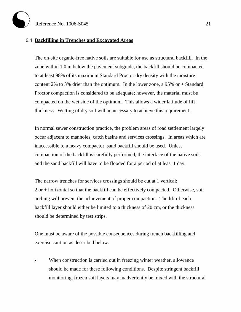
6.4 Backfilling in Trenches and Excavated Areas
The on-site organic-free native soils are suitable for use as structural backfill. In the
zone within 1.0 m below the pavement subgrade, the backfill should be compacted
to at least 98% of its maximum Standard Proctor dry density with the moisture
content 2% to 3% drier than the optimum. In the lower zone, a 95% or + Standard
Proctor compaction is considered to be adequate; however, the material must be
compacted on the wet side of the optimum. This allows a wider latitude of lift
thickness. Wetting of dry soil will be necessary to achieve this requirement.
In normal sewer construction practice, the problem areas of road settlement largely
occur adjacent to manholes, catch basins and services crossings. In areas which are
inaccessible to a heavy compactor, sand backfill should be used. Unless
compaction of the backfill is carefully performed, the interface of the native soils
and the sand backfill will have to be flooded for a period of at least 1 day.
The narrow trenches for services crossings should be cut at 1 vertical:
2 or + horizontal so that the backfill can be effectively compacted. Otherwise, soil
arching will prevent the achievement of proper compaction. The lift of each
backfill layer should either be limited to a thickness of 20 cm, or the thickness
should be determined by test strips.
One must be aware of the possible consequences during trench backfilling and
exercise caution as described below:
• When construction is carried out in freezing winter weather, allowance
should be made for these following conditions. Despite stringent backfill
monitoring, frozen soil layers may inadvertently be mixed with the structural

Reference No. 1006-S045 22
trench backfill. Should the in situ soil have a water content on the dry side of
the optimum, it would be impossible to wet the soil due to the freezing
condition, rendering difficulties in obtaining uniform and proper compaction.
Furthermore, the freezing condition will prevent flooding of the backfill
when it is required, such as when the trench box is removed. The above will
invariably cause backfill settlement that may become evident within 1 to
several years, depending on the depth of the trench which has been
backfilled.
• In areas where the underground services construction is carried out during
winter months, prolonged exposure of the trench walls will result in frost
heave within the soil mantle of the walls. This may result in some settlement
as the frost recedes, and repair costs will be incurred prior to final surfacing
of the new pavement.
• To backfill a deep trench, one must be aware that future settlement is to be
expected, unless the side of the cut is flattened to at least 1 vertical:
1.5+ horizontal, and the lifts of the fill and its moisture content are
stringently controlled; i.e., lifts should be no more than 20 cm (or less if the
backfilling conditions dictate) and uniformly compacted to achieve at least
95% of the maximum Standard Proctor dry density, with the moisture
content on the wet side of the optimum.
• It is often difficult to achieve uniform compaction of the backfill in the lower
vertical section of a trench which is an open cut or is stabilized by a trench
box, particularly in the sector close to the trench walls or the sides of the
box. These sectors must be backfilled with sand. In a trench stabilized by a
trench box, the void left after the removal of the box will be filled by the
backfill. It is necessary to backfill this sector with sand, and the compacted
backfill must be flooded for 1 day, prior to the placement of the backfill
above this sector, i.e., in the upper sloped trench section. This measure is

Reference No. 1006-S045 23
necessary in order to prevent consolidation of inadvertent voids and loose
backfill which will compromise the compaction of the backfill in the upper
section. In areas where groundwater movement is expected in the sand fill
mantle, seepage collars should be provided.
6.5 Garages, Driveways and Landscaping
As noted, the encountered soils are moderately frost susceptible, with moderate soil-
adfreezing potential; therefore, the ground is expected to heave during cold weather.
The driveway at entrances to the garages must be backfilled with non-frost-
susceptible granular material, with a frost taper at a slope of 1 vertical:1 horizontal.
The garage floor slab and interior garage foundation walls must be insulated with
50-mm Styrofoam, or equivalent. The recommended scheme is illustrated in
Diagram 2.
Diagram 2 - Frost Protection Measures (Garage)
Weeper Encased in Fabric Filter
Non-Frost-SusceptibleGranular
1.0
1.0
Insulation Granular Base
Driveway Garage Floor Slab
Insulation

Reference No. 1006-S045 24
The slab-on-grade in open areas should be designed to tolerate frost heave, and the
grading around the slab-on-grade must be such that it directs runoff away from the
structure.
In areas where ground movement due to frost heave cannot be tolerated, the
slab-on-grade, sidewalks and interlocking stone pavement must be constructed on a
free-draining granular base, 0.3 to 1.2 m thick, depending on the degree of tolerance
for settlement. Alternatively, the slab-on-grade, sidewalks and interlocking stone
pavement should be insulated with 50-mm Styrofoam, or equivalent.
6.6 Pavement Design
Based on the borehole findings, the pavement subgrade will consist mainly of silty
clay till. Accordingly, the recommended pavement design for local and collector
roads is presented in Table 4.
Table 4 - Pavement Design
Thickness (mm)
Course Local Collector OPS Specifications
Asphalt Surface 40 40 HL-3
Asphalt Binder 65 90 HL-8
Granular Base 150 150 Granular ‘A’
Granular Sub-base 300 450 Granular ‘B’
Prior to placement of the granular bases, the subgrade surface should be proof-
rolled, and any soft subgrade should be subexcavated and replaced by properly
compacted inorganic earth fill or granular material. All the granular bases should
be compacted to their maximum Standard Proctor dry density.

Reference No. 1006-S045 25
The earth fill in the zone within 1.0 m below the pavement must be compacted to
98% or + of its maximum Standard Proctor dry density, with the moisture content
2% to 3% drier than the optimum. In the lower zone, a 95% or + Standard Proctor
compaction is considered adequate.
The pavement subgrade will suffer a strength regression if water is allowed to
infiltrate prior to paving. The following measures should therefore be incorporated
in the construction procedures and pavement design:
• If the roads construction does not immediately follow the trench backfilling,
the subgrade should be properly crowned and smooth-rolled to allow interim
precipitation to be properly drained.
• The areas adjacent to the roads should be properly graded to prevent the
ponding of large amounts of water during the interim construction period.
• Curb subdrains will be required. The subdrains should consist of filter-
sleeved weepers to prevent blockage by sitting.
• If the pavement is to be constructed during the wet seasons and extensively
soft subgrade occurs, the granular sub-base may require thickening. This can
be assessed during construction.
6.7 Soil Parameters
The recommended soil parameters for the project design are given in Table 5.

Reference No. 1006-S045 26
Table 5 - Soil Parameters
Unit Weight and Bulk Factor
Unit Weight (kN/m3)
Estimated Bulk Factor
Bulk Loose Compacted
Earth Fill 20.5 1.20 0.98
Silty Clay Till 22.0 1.30 1.05
Lateral Earth Pressure Coefficients
Active Ka
At Rest Ko
Passive Kp
Earth Fill 0.50 0.60 2.22
Silty Clay Till 0.35 0.45 2.85
Maximum Allowable Soil Pressures (SLS) For Thrust Block Design (kPa)
Engineered Fill 100
Sound Natural Soil 150
6.8 Excavation
Excavation should be carried out in accordance with Ontario Regulation 213/91.
The sides of the excavation should be cut at 1 vertical:1 or + horizontal and may
need to be flattened to 1 vertical:1.5 or + horizontal in the earth fill. The spoil from
the excavation and/or trenches must be placed at a distance from the edge of the
excavation equal to twice the depth of the excavation.
For excavation purposes, the types of soils are classified in Table 6.

Reference No. 1006-S045 27
Table 6 - Classification of Soils for Excavation
Material Type
Sound Natural Soil 2
Earth Fill and weathered Till 3
The groundwater yield from the encountered soil, due to its relatively low
permeability, will be small and can be controlled by pumping from sumps.
Excavation into the hard silty clay till containing boulders will require extra effort
and the use of a heavy-duty, properly equipped backhoe.
Prospective contractors must be asked to assess the in situ subsurface conditions for
soil cuts by digging test pits to at least 0.5 m below the intended bottom of
excavation. These test pits should be allowed to remain open for a period of at least
4 hours to assess the trenching conditions.


Soil Engineers Ltd. Reference No: 1006-S045
U.S. BUREAU OF SOILS CLASSIFICATION
COARSE
UNIFIED SOIL CLASSIFICATION
COARSE
Project: Proposed Residential Development
Location: 13576 and 13584 Coleraine Drive, Town of Bolton Liquid Limit (%) = -
Plastic Limit (%) = -
Borehole No: 1 Plasticity Index (%) = -
Sample No: 3 Moisture Content (%) = 21
Depth (m): 1.8 Estimated Permeability
Elevation (m): 99.7 (cm./sec.) = 10-7
Classification of Sample [& Group Symbol]: EARTH, Fill
silty clay, some sand and a trace of gravel
SILT & CLAY
Figure: 5
COARSE
MEDIUM
FINE
CLAY
SAND
MEDIUMFINE
GRAVEL
GRAIN SIZE DISTRIBUTION
SAND
V. FINE
GRAVELSILT
COARSE FINEFINE
3" 2-1/2" 2" 1-1/2" 1" 3/4" 1/2" 3/8" 4 8 10 16 20 30 40 50 60 100 140 200 270 325
0
10
20
30
40
50
60
70
80
90
100
0.0010.010.1110100
Perc
ent P
assi
ng
Grain Size in millimeters

Reference No: 1006-S045
U.S. BUREAU OF SOILS CLASSIFICATION
COARSE
UNIFIED SOIL CLASSIFICATION
COARSE
Project: Proposed Residential Development BH./Sa. 1/5 2/4 3/6 4/4
Location: 13576 and 13584 Coleraine Drive, Town of Bolton Liquid Limit (%) = 31 32 33 29
Plastic Limit (%) = 18 19 19 17
Borehole No: 1 2 3 4 Plasticity Index (%) = 13 13 14 12
Sample No: 5 4 6 4 Moisture Content (%) = 16 14 21 12
Depth (m): 3.3 2.5 4.8 2.5 Estimated Permeability Elevation (m): 98.2 93.9 91.3 97.6 (cm./sec.) = 10-7 10-7 10-7 10-7
Classification of Sample [& Group Symbol]: SILTY CLAY, Till
a trace of sand to sandy, a trace of gravel
GRAIN SIZE DISTRIBUTION
SAND
V. FINE
GRAVELSILT
COARSE FINEFINE
SILT & CLAY
Figure: 6
COARSE
MEDIUM
FINE
CLAY
SAND
MEDIUMFINE
GRAVEL
3" 2-1/2" 2" 1-1/2" 1" 3/4" 1/2" 3/8" 4 8 10 16 20 30 40 50 60 100 140 200 270 325
0
10
20
30
40
50
60
70
80
90
100
0.0010.010.1110100
Perc
ent P
assi
ng
Grain Size in millimeters
BH.3/Sa.6
BH.2/Sa.4
BH.1/Sa.5
BH.4/Sa.4

BOREHOLE LOCATION PLAN AND SUBSURFACE PROFILE Ref. No.: 1006-S045 Date: May 2013 Drawing No.: 1 Scale: Vert.: 1:100 Horiz.: 1:400 SOIL ENGINEERS LTD.
BH.3
LEGEND
TOPSOIL/TOPSOIL FILL
EARTH FILL
SILTY CLAY TILL
WATER LEVEL
BH.2
BH.1
BH.4
N
B.M. El. 100.00 m (assumed)