A refractive index comparator for the · PDF fileA refractive index comparator for the ... and...
9
438 A refractive index comparator for the microscope. By A. T. J. DOLLAR, Ph.D., B.Sc., A.K.C. Department of Geology, University of Glasgow. [Exhibited March 10, 1938.] T HIS stage-attachment simplifies microscopic comparison of refrac' tire indices of small transparent grains by the immersion-liquid methods of O. Maschke, 1 Schroeder van der Kolk, ~ and other workers. It was designed in 1938 for use in mineralogy and petrology, but has applications in several branches of pure and applied chemistry, patti- cularly for determining the relative purities of numerous raw materials and refined products of the chemical industry and in checking the constituents of glasses, slags, refractories, and cements. It can be used with advantage, also, in the optical study of soils. The device enables the composition of a suitable liquid to be changed by small increments of any desired magnitude between certain limits, in a nearly closed transparent vessel under the microscope, until there is little or no significant difference between the refractive index of this liquid and either the refractive index, or a refractive index, of grains immersed in it, as judged by the Becke method of central illumination 3 or the van der Kolk method of oblique illumination. 4 A suitable refracto- meter is then used for finding the refractive index of this final liquid. With due care the value of the refractive index so derived can have an accuracy of about +0.002, or better, if monochromatic light is used throughout and appropriate temperature corrections are applied. The aim of the instrument is to increase the rate and convenience with which immersion-liquid refractive index comparisons can be made by providing simpler and more efficient means for mixing the necessary liquids than is involved in the method of stirring together drops of liquids of known refractive indices on a plane glass slip, or in a small 10. Maschke, Pogg. Ann., 1872, vol. 145, pp. 565-568; Niedemann's Ann. Physik, 1880, vol. 11, pp. 722-734. 2 j. L. C. Schroeder van der Kolk, Kurze Anleitung z.ur mikroskopischen Kry- stallbestimmung. Wiesbaden, 1898, pp. 11-14. Tabellen zur mikroskopischen Bestimmung der Mineralien nach ihren Brechungsindex. Wiesbaden, 2 Aufl., 1906. a F. Beeke, Sitz.-ber. Akad. Wiss. Wien, 1893, vol. 102, Abt. I, pp. 358-378. 4 j. L. C. Schroeder van der Kolk, Zeits. wiss. Mikroskopie, 1892, vol. 8, pp. 456- 458.
Transcript of A refractive index comparator for the · PDF fileA refractive index comparator for the ... and...

438
A refractive index comparator for the microscope.
By A. T. J. DOLLAR, Ph.D., B.Sc., A.K.C.
Depar tment of Geology, Universi ty of Glasgow.
[Exhibited March 10, 1938.]
T HIS stage-at tachment simplifies microscopic comparison of refrac ' t i r e indices of small t ransparent grains by the immersion-liquid
methods of O. Maschke, 1 Schroeder van der Kolk, ~ and other workers. I t was designed in 1938 for use in mineralogy and petrology, but has applications in several branches of pure and applied chemistry, pa t t i - cularly for determining the relative purities of numerous raw materials and refined products of the chemical industry and in checking the constituents of glasses, slags, refractories, and cements. I t can be used with advantage, also, in the optical s tudy of soils.
The device enables the composition of a suitable liquid to be changed by small increments of any desired magnitude between certain limits, in a nearly closed t ransparent vessel under the microscope, until there is li t t le or no significant difference between the refractive index of this liquid and either the refractive index, or a refractive index, of grains immersed in it, as judged by the Becke method of central i l lumination 3 or the van der Kolk method of oblique illumination. 4 A suitable refracto- meter is then used for finding the refractive index of this final liquid. With due care the value of the refractive index so derived can have an accuracy of about +0.002, or better, if monochromatic light is used throughout and appropriate temperature corrections are applied.
The aim of the instrument is to increase the rate and convenience with which immersion-liquid refractive index comparisons can be made by providing simpler and more efficient means for mixing the necessary liquids t h a n is involved in the method of stirring together drops of liquids of known refractive indices on a plane glass slip, or in a small
10 . Maschke, Pogg. Ann., 1872, vol. 145, pp. 565-568; Niedemann's Ann. Physik, 1880, vol. 11, pp. 722-734.
2 j . L. C. Schroeder van der Kolk, Kurze Anleitung z.ur mikroskopischen Kry- stallbestimmung. Wiesbaden, 1898, pp. 11-14. Tabellen zur mikroskopischen Bestimmung der Mineralien nach ihren Brechungsindex. Wiesbaden, 2 Aufl., 1906.
a F. Beeke, Sitz.-ber. Akad. Wiss. Wien, 1893, vol. 102, Abt. I, pp. 358-378. 4 j . L. C. Schroeder van der Kolk, Zeits. wiss. Mikroskopie, 1892, vol. 8, pp. 456-
458.
REFRACTIVE INDEX COMFARATOI~ 4 3 9
glass cell. More especially it enables the whole process of comparison to be carried out, step by step, in a single dust-free container, to be observed continuously under the microscope, and to be controlled closely throughout. Further, at the end of this process of comparison any tendency for a slight change to occur in the refractive index of the final mixture of liquids, due to differential evaporation, is minimized by the fact that the main vessel is "sealed except for a pin-hole at one point.
The material and form of the instrmnent as a whole give a combina- tion of lightness with the necessary mechanical strength (fig. 1). Further, its size is such that it can be accommodated On the stage and rotated through 360 ~ about the objective of any modern petrographic micro- scope (fig. 2). I t is noteworthy that, without losing these advantages, the instrument could be made nearly half as large again than it is at present, thereby increasing the range of certain of its cgpabiiities. The highest power of objective which can be used in conjunction with the device is determined by the fact that a minimum separation of 3.5 mm. must be maintained between the lower surface of this objective and the upper surface of the microscope stage if the objective is to be Prevented from touching the liquid mixing-chamber of the instrument. The shape and internal dimensions of the main vessel have been so chosen that clogging by wedged particles of test material is. unlikely unless the particles are more than 1.5 ram. in maximum diameter. Finally, appro- priate parts of the device can be assembled, filled, emptied, separated, and cleaned with ease and rapidity.
In use, the two most "important advantages of the instrument are: (i) that it enables the desired refractive index comparison to be made as a simple progressive operation not involving, for'example, repeated transfer of a minute grain, or grains, from a volume of one liquid to that of another, with consequent manipulative and optical complica- tions ; and (ii) that relatively small total volumes of immersion liquids (less than 0-6 c.c.) can be employed while retaining adequate accuracy in the values of refractive indices so obtained. Additional optical advantages are that any desired grains can be centred in the field of view and then rotated completely on the microscope stage, and that a platy particle can be tilted and held thus (on its edge, if desired), for microscopic study, by means of controlled air bubbles in the immersion liquid, as is described below.
Though it involves an immersion liquid mixing-chamber comparable with the open glass cell employed by some workers, this instrument differs from the latter in being a nearly closed main vessel carrying a
440 A . T . J . DOLLAR ON
small detachable reservoir from which drops of a suitable immersion liquid can be introduced into the main vessel at will, and in using a pneumatic method for thoroughly mixing these drops, one or more at a
L
J
G
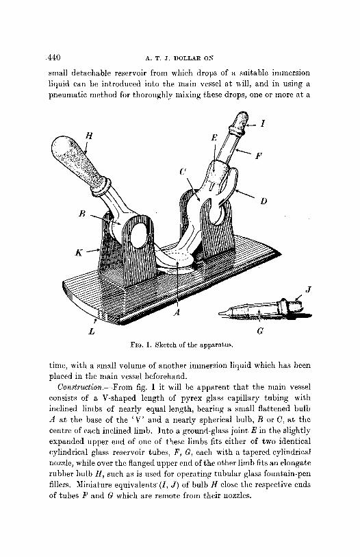
FIG. 1. Sketch of the apparatus.
time, with a small volume of another immersion liquid which has been placed in the main vessel beforehand.
Construction.--From fig. 1 it will be apparent that the main vessel consists of a V-shaped length of pyrex glass capillary tubing with inclined limbs of nearly equal length, bearing a sm,~ll flattened bulb A at the base of the ' V' and a nearly spherical bulb, B or 0, at the centre of each inclined limb. Into a ground-glass joint E in the slightly expanded upper end of one of these limbs fits either of two identical cylindrical glass reservoir tubes, F, G, each with a tapered cylindrical nozzle, while over the flanged upper end of the other limb fits an elongate rubber bulb H, such as is used for operating tubular glass fountain-pen fillers. Miniature equivalents (I, J) of bulb H close the respective ends of tubes F and G which are remote from their nozzles.

REFRACTIVE 1NDEX COMFARATOR 441
Glass bulb A is the chamber in which par t of the mixing of immersion liquids occurs and where subsequent refractive iudex comparisons are ntade. Its upper and lower walls are parallel and have a thickness of about 0.5 ram. The external depth of the chamber is 2"5 ram.
The glass bulbs B and C serve not only as terminal reservoirs and mixing-chambers for immersion liquids but also as retarding devices to check any tendency for a rapid rise of these liquids into contact with the nozzle of either tube F or tube G (whichever is being used in the instru- ment at the time), or with the rubber of bulb H. Bulb C has a short cylindrical branch tube D, fused into it a t a point on the surface of the bulb near its upper junction with the main tube. This branch tube is curved upwards, away from the bulb, into approximate parallelism with the main tube aud its upper end is level with the top edge of the latter. Here D is closed except for a circular hole, nearly three- quarters of a millimetre in diameter, which allows air to enter or leave bulb C and its associated parts of the main tube when an immersion liquid is withdrawn from or forced into bulb C by manipulat ion of rubber bulb H, but minimizes the chance of loss of any such liquid tha t might rise high in bulb C. Further , evaporation through such a vent at normal laboratory temperatures is so small as to be negligible for any but long periods of time. Tiffs means tha t over the usual duration of a laboratory determination, changes in the refractive index of an immersion liquid in the main tube due to differential evaporation and loss of a more volatile component from a less volatile one can be neglected in practice.
Each of the identical cylindrical glass reservoir tubes F, G has at one end a smooth-edged, cylindrical nozzle, 0"9 ram. in external diameter, carefully shaped to give small drops of refractive index liquid, while at the other end is a miniature rubber bulb, I or J , for expelling these drops. Such a bulb is made from the closed end of a fountain-pen ink- sack. On the exterior of the tube immediately above the nozzle is a conical surface which has been ground to make a very close union with a complement ' l ry ground surface E in the main tube. The uniformity of drops generated from these nozzles must be preserved by keeping the la t ter scrupulously clean and not allowing them to become chipped as a result of careless handling.
To ensure rapid recovery of form after compression, bulb H is com- posed of heavy resilient rubber, while its open end is of such a diameter and so thickened tha t i t makes a thoroughly air t ight union with the surface of the main tube. Care must be taken to prevent any of the immersion liquids which react with rubber from reaching the interior
Ff

442 A . T . J . D O L L A R ON
of this bulb or the refractive index of the liquid in the mahl tube may be changed by admixture with such solutions and the walls of the bulb
caused to stick together when the latter is compressed between the fingers.
The phosphor bronze springoclip K has two pairs of nearly vertical members with circular holes cut in them of a size such that they receive and grip the nearly spherical glass bulbs B and C when the main tube is pressed down between these members. One of the four members is modified to accommodate the small vent-tube D projecting from bulb C. This simple spring-clip serves not only as a convenient holder for the main tube, accept- ing or releasing it in a moment, but also acts as a double ball-pivot which allows the main tube to be swung through 5 ~ either side of the vertical position about a horizontal axis joining the centres of bulbs B and C. Among other advantages this last possibility enables grains of material under examination in bulb A to be segregated, by suitable tilting of the main tube, in a part of the bulb where they will not be
Fro. 2. The apparatus in operating swept into the main stream of im- position on the mierosc.ope stage, mersion liquids which are circulated with the bulbs and reservoir tube through A (luring the nfixing of
partly filled with liquid. these liquids.
The base plate L of the whole device is a small rectangular strip of stiff bakelite tibre, little more than twice the thickness of most glass specimen slides. I t has a central hole through which light reaches bulb A front below when the instrument is attached to a microscope. This plate is held in position on the microscope stage by the usual pair of clips provided for holding specimen slides (fig. 2). Consequences of

REFRACTIVE INDEX COMPARATOR 443
this mode of attachment are that the contents of bulb A can be explored, or any desired grain centred for optical tests, by appropriate small movements of L under the slide-clips. While using the instrument, the microscope stage should be maintained in the horizontal position throughout.
Opera2ion.--As a preliminary to the refractive index determination of constituents in a solid sample a representative piece is crushed, but not ground, and then screened to provide particles preferably between 0.5 and 1 ram. in diameter. Should it bc necessary, the instrument can accommodate particles up to 1"5 nun. in diameter. I f the sample is a detrital sediment or other type of granular material, any initial treat- ment must be followed by screening, to remove grains greater than ] '5 ram. in diameter.
This is followed, if necessary, by a determination of the approximate refractive index or refractive indices of grains of this screened material, made with a set of immersion liquids differing in refringence by, say, 0.01.
A small amount of the screened material is then introduced into the lower part of bulb B with a spatula made from a short length of lleavy- gauge platinum wire 1 flattened into a minute blade at, one end, and from here the sample is introduced into bulb A by suitable tapping.
Any grains remaining in B are washed into ,4 (luring the subsequent addition of a definite number of drops of immersion liquid x (say, of a refractive index lower than that of the sample) from reservoir tube G.
The body of liquid resulting from the coalescence of these drops may fill part or all of bulb A and more or less of the main tube connecting ,4 with B. I f this last is the case, to prevent accumulation of liquid in the tube when further drops of liquid are added to bulb B, air is displaced from bulb H by squeezing the bulb--which air passes through A into C in the form of bubbles and thereby allows the level of liquid to fall in the tube connecting A With B and rise proportionately in the tube connecting A with C.
Reservoir tube F is nearly rifle(1 with immersion liquid y (which has a higher refractive index than that of the sample and is miscible with immersion liquid x in all proportions) and careflfily inserted in ground joint E.
The main tube is then pressed into spring-clip K and the whole device placed on the stage of a petrographic microscope with the slide-clips of the latter gripping the base plate L. The stage is then set horizontally
1 No. 19 S.W.G. is suitable, and the length may be fused into one end of a small glass rod fur greater manipulative convenience.

4 ~ A.T.J . 1)OLLAB. ON
and the apparatus manipulated under the clips to centre any required grain, or group of grains, in the field of view.
A drop of li<tuid y is expelled from F into the lower part of bulb C by means of the left hand, after which gentle pressure on bulb H between finger and thumb of the right hand causes a column of the liquid x to rise into the lower part of bulb C, followed by a train of bubbles of air from bulb H, thereby mixing this liquid to some extent with the drop of liquid y. On relaxing the pressure on H, the still relatively inhomo- geneous mixture of x and y retreats into and through A, followed by a series of air bubbles drawn from bulb C, which bubbles thoroughly agitate and stir the mixture. On repeating this oscillatory circulation of the mixture and bubbles four or five times in rapid succession, by alternate increases and decreases of pressure on blllb H, the essential optical homogeneity of the mixture is attained very rapidly and con- veniently, after which a refractive index comparison can be made between it and a chosen grain by either the method of central illumina- tion or that of oblique illumination, using monochromatic light.
There.after additional drops of liquid y 'ire expelled from F, one at a time, each mixed in the manner already described, and a corresponding refractive index comparison made with the grain or grains at each step until optical match is obtained. Should one or more drops of y be added in excess of what is rc(tuired for match, reservoir tube F is replaced by reservoir tube G, containing liquid x, and from it is added to the mixture of liquids the necessary number of drops to rectify the error.
If, during the mixing process described, grains tend to be swept from bulb A into either bulb B or bulb C, or both, by the stream of immersion liquid, the main tube can be swung in its spring-clip through approxi- mately 5 ~ either side of its normal vertical position about an axis joining the centrcs of bulbs B and C, so that test grains fall, or rise, 1 to the side of A remote from the main tube, i.e. into a 'backwater ' out of the main stream of liquid, until the mixing process is completed.
By suitable manipulation of bulb H, trains of a few large air bubbles (or a larger number of small air bubbles) can be induced in the main column of liquid. With a little practice such bubbles can be used to tilt and hold platy grains on edge, for optic'~l examination, aided by a slight cant of the main tube in its spring-clip to help to introduce such grains into the bubble-train which may then be caused to circulate round
I)epending upon the direction of tilt of the main tube and upon whether the specific gravities of the grains are greater or less than the specific gravity of the immersion liquid.

I~EFRACTIVE INDEX COMI)AI~AT()I)~ 445
only one side of bulb A. In use this technique is as simple and effective as tha t described by E. S. Larsen 1 for turning small mineral plates in a relatively viscous immersion liquid to s tudy their optics.
As SQOn as the final liquid mixture is obtained the whole device is removed from the microscope stage, tube F is withdrawn, and a drop of the liquid expelled onto a refractometer prism for direct refractive index measurement at a known temperature, using monochromatic light. I f i t is not convenient to make this measurement immediately, the final mixture of x and y can be left in the instrument for a con- siderable period of t ime without fear of any significant change of com- position and therefore of refractive index, due to differential evaporation, provided F is left in position throughout, or replaced by a small well- fitting ground-glass stopper immediately the matching process is complete.
After use the main tube and reservoir tubes of the instrument should be cleaned with benzene, or sonle other solvent appropriate to the immersion liquid employed, using bulb H for circulating the solvent thoroughly in the main tube, but carefully preventing the solvent from wetting this bulb.
Uti l i ty . - -Experience gained with this apparatus over the past ten years has shown tha t it is especially suitable for refractive index deter-
m i n a t i o n s on small detr i tal particles, crushed fragments of minerals, and such microscopic crystals and crystalline aggregates as occur in some soils and in a number of raw and manufactured industrial materials.
Most commonly the device serves as a convenient aid in measuring one refractive index of a given material, bu t two or three refractive indices of the same material, or of an association of different materials, can be determined successively and during one and the same main operation if the greatest numerical difference between the refringences concerned is sufficiently small and appropriate immersion liquids are employed.
From a relationship discussed by C. Christiansen 2 i t can be shown that , for light of a chosen wave-length, and at a given temperature, the refractive index n of a mixture of two immersion liquids x and y is given by the expression:
n = (vx n~ + v , ~,~)/(v~ +v, , ) ,
where v~, v V are the volumes of liquids having refractive indices n~ and
1 E. S. Larsen, Bull. U.S. Geol. Surv., 1921, no. 679, pp. 22-23. 2 C. Christial~cn, Niedcmann's Ann. Physik, 1884, vol. 22, p. 298; 1885,
vol. 24, p. 439.

446 A.T.J . DOLLAR ON REFRACTIVE INDEX COMPARATOR
nv respectively, for light of the chosen wave-length and at the tempe- rature concerned.
In the apparatus here described the total effective volume of either reservoir tube is 0"15 c.c., and that of the main tube is 0.45 e.c., i.e. a volume ratio of 1 : 3 is afforded. The significant unit of volume, however , is not the cubic centimetre but the drop of any given immersion liquid which is obtainable from the nozzle of either F or G, since this determines the magnitude of each successive change of refractive index t h a t can be produced when two immersion liquids of different refractive indices are mixed in the instrument. From a clean smooth nozzle of the form shown in fig. 1, and for a given gaseous environment, the volumes of successive drops of a chosen liquid are sensibly equal, bu t differ in this respect from one liquid to another, since at a given temperature the volumes are functions of the surface tensions of the liquids concerned. 1
Experiment shows t h a t an average of 12 drops of liquid can be obtained from a single filling of either reservoir tube and ther.efore a maximum of about 36 drops can be accommodated in the main tube of the device. This gives possible extreme ratios vx:v~ = 1:35 or 35:1, and proportionate values of n.
These are not the limiting ratios obtainable, however, since the drops discussed hitherto are what may be termed 'full ' drops, which form and fall naturally from the nozzle of F or G on compressing bulb I or J sufficiently, whereas drops of about half this volume, or less, can be derived from the same nozzles by expressing the necessarily smaller amounts of liquid and then causing the hanging droplets to separate and fall to the bottom of bulb C by a light tap with the finger-nail, or a pencil, on the outside of ground joint E. Such 'half-drops' can change the ratio v~:v v to extreme values of the order 1:70 or 70:1, thereby reducing the effective magnitude of the change of n in proportion. I t will be evident that such half-drops, or still smaller drops, need to be employed only when the refractive index of a liquid mixture and that of its immersed grains are very nearly equal.
The author is grateful to the late Mr. F. Niedergersass for shaping the necessary glass parts of the first model of this apparatus, and to Mr. A. N. Lanham, chief laboratory assistant in the Department of Mineralogy and Petrology, University of Cambridge, for making its base plate.
1 W. D. Harkins and F. E. Brown, Journ. Amer. Chem. Soc., 1919, vol. 41, pp. 499-524.