A Reference Manual - Humanitarian Library
24
A Reference Manual Disaster Resistant Construction Practices
Transcript of A Reference Manual - Humanitarian Library

A Reference Manual
Disaster Resistant Construction Practices
Disaster Resistant Construction Practices
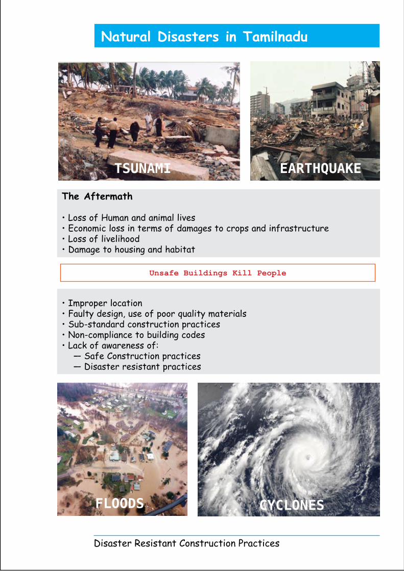
Natural Disasters in Tamilnadu
The Aftermath
• Loss of Human and animal lives• Economic loss in terms of damages to crops and infrastructure• Loss of livelihood• Damage to housing and habitat
• Improper location• Faulty design, use of poor quality materials • Sub-standard construction practices• Non-compliance to building codes• Lack of awareness of: — Safe Construction practices — Disaster resistant practices
FLOODS
TSUNAMI EARTHQUAKE
CYCLONES
Unsafe Buildings Kill People

Disaster Resistant construction practices are as important as disaster resistant structrual designs. Infact the methodology for construction also should be designed for disaster resistance. We should have proper implemenation of the structural details so as to let the structure behave as envisiged.
The quality and methodology of construction is equally important. For example we use cover blocks. If the cover blocks are not cast properly in good quality concrete then they facilitate concrete deterioration. Ultimately this affects durability and serviceablity of the structure.
The Durability and serviceablity are the key elements of any structure. Ensuring Quality in construction will enable achieving durability and serviceablity as a desired end result.
Usually a building comprises of:
1. Walls2. Openings3. Foundation4. Plinth5. Beams/Columns6. Roof / Slabs
Parts of aBuilding
Disaster Resistant Construction Practices
Introduction
Deficient Bond at corners
Differential settlement due to soft soil
Use of Cut Lintels
Too high and long
walls
Openings too close to corners
Vulnerable Parts of a Building

PROVIDE- Separation of wings into different rectangles in plan is preferable
PROVIDE- Shorter wall facing wind direction
AVOID- Longer wall facing the direction of wind
PROVIDE- Clustered (zigzag) planning avoids tunneling effect and reduces susceptibility to disaster
AVOID- Row house settlement with roads leading to Sea
PROVIDE- Simple Square/Rectangular and Symmetrical plan is Suitable- Length of Building ≤ 2xWidth
Disaster Resistant Construction Practices
Settlement pattern and Design Considerations
1.1
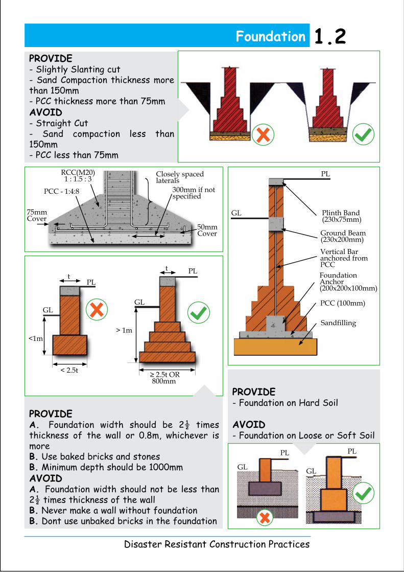
PROVIDEA. Foundation width should be 2½ times thickness of the wall or 0.8m, whichever is moreB. Use baked bricks and stonesB. Minimum depth should be 1000mmAVOIDA. Foundation width should not be less than 2½ times thickness of the wallB. Never make a wall without foundationB. Dont use unbaked bricks in the foundation
PROVIDE- Foundation on Hard Soil
AVOID- Foundation on Loose or Soft Soil
PROVIDE- Slightly Slanting cut- Sand Compaction thickness more than 150mm- PCC thickness more than 75mmAVOID- Straight Cut- Sand compaction less than 150mm- PCC less than 75mm
t
<1m
< 2.5t
GL
PL
≥ 2.5t OR 800mm
> 1m
t PL
GL
PLPL
GL GL
}Closely spaced laterals
RCC(M20)1 : 1.5 : 3
PCC - 1:4:8 300mm if not specified
75mm Cover
50mm Cover
Plinth Band (230x75mm)
Ground Beam (230x200mm)
Foundation Anchor(200x200x100mm)
PCC (100mm)
Sandfilling
PL
GL
Vertical Bar anchored from PCC
Disaster Resistant Construction Practices
1.2Foundation

PROVIDE- Average wall height should be 2700 to 3000mm
AVOID- Too High Walls
PROVIDE- The length of the wall should not exceed 8 times the thickness- Addition of a buttress wall reduces L/H Ratio
AVOID- Walls that are too high or too long
Stone Masonry
A. Through stone should be placed horizontally at a minimum spacing of 1200mm center-to-centerB. Through stone should be placed vertically at a minimum-spacing of 600mm
Vertical Corner Reinforcement embedded in M20 Concrete
A C
1200
1200
450
600
600
1200
1200
PlanBSection Plan
Disaster Resistant Construction Practices
1.3 Walls
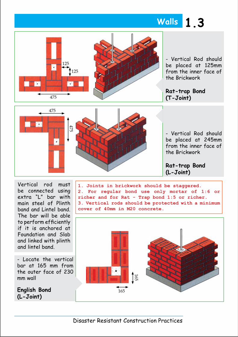
- Locate the vertical bar at 165 mm from the outer face of 230 mm wall
English Bond (L-Joint)
- Vertical Rod should be placed at 245mm from the inner face of the Brickwork
Rat-trap Bond (L-Joint)
- Vertical Rod should be placed at 125mm from the inner face of the Brickwork
Rat-trap Bond(T-Joint)
Vertical rod must be connected using extra “L” bar with main steel of Plinth band and Lintel band. The bar will be able to perform efficiently if it is anchored at Foundation and Slab and linked with plinth and lintel band.
1. Joints in brickwork should be staggered.2. For regular bond use only mortar of 1:6 or richer and for Rat - Trap bond 1:5 or richer. 3. Vertical rods should be protected with a minimum cover of 40mm in M20 concrete.
125
125
475
475
475
165
165
Disaster Resistant Construction Practices
1.3Walls
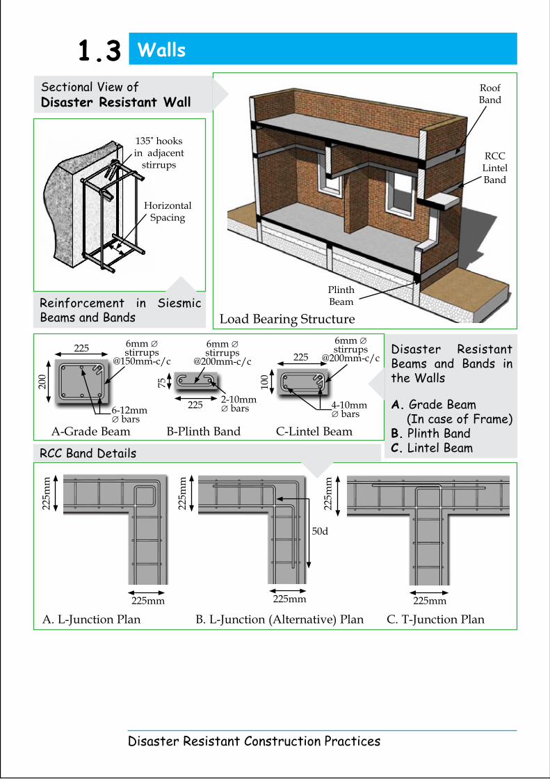
RCC Band Details
Disaster Resistant Beams and Bands in the Walls
A. Grade Beam (In case of Frame)B. Plinth BandC. Lintel Beam
Reinforcement in Siesmic Beams and Bands
Sectional View of Disaster Resistant Wall
225m
m
225mm
225m
m
225mm
6mm ∅ stirrups
@200mm-c/c
4-10mm ∅ bars
100
225
225
75
6mm ∅ stirrups
@200mm-c/c
2-10mm ∅ bars
6mm ∅ stirrups
@150mm-c/c
200
225
6-12mm ∅ bars
225m
m
225mm
50d
Disaster Resistant Construction Practices
Walls1.3
Plinth Beam
RCC Lintel Band
Roof Band
135˚ hooks in adjacent
stirrups
Horizontal Spacing
Load Bearing Structure
A-Grade Beam B-Plinth Band C-Lintel Beam
A. L-Junction Plan B. L-Junction (Alternative) Plan C. T-Junction Plan
Design Considerations
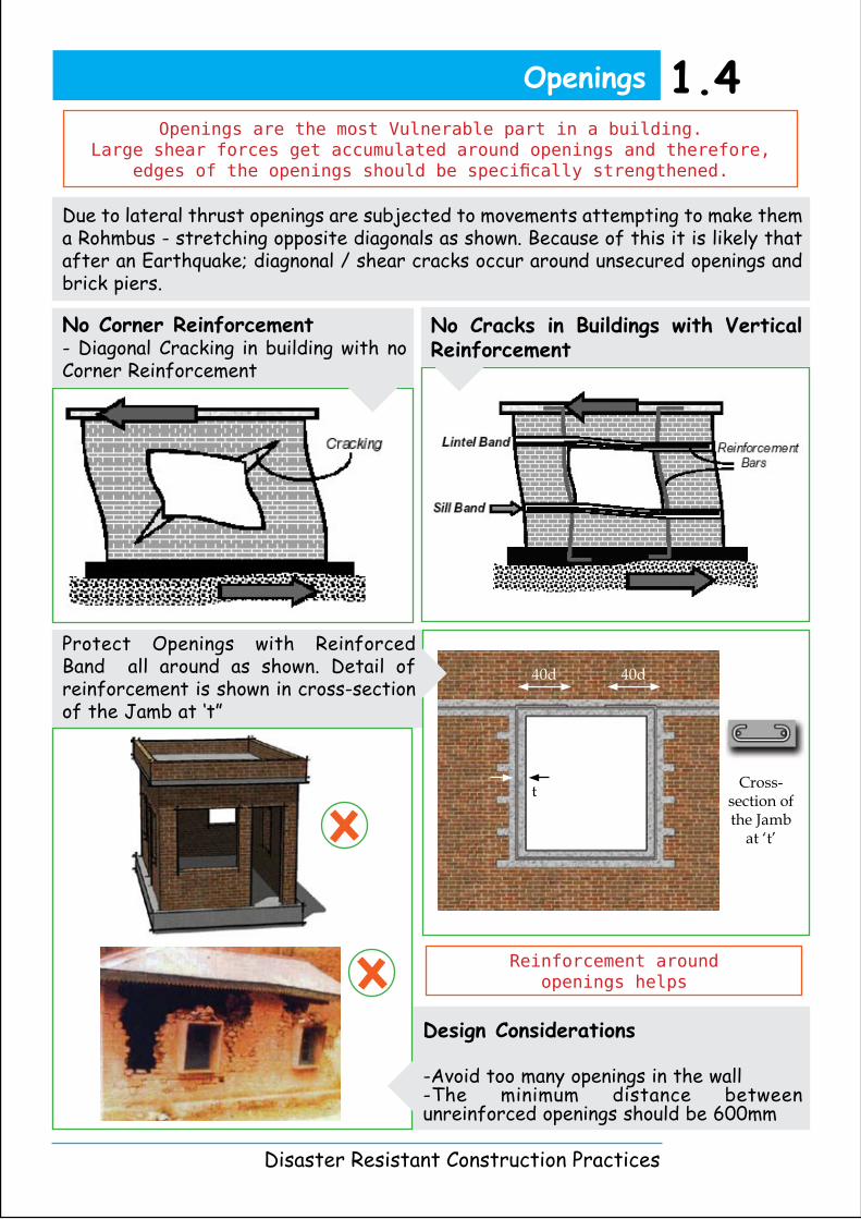
-Avoid too many openings in the wall-The minimum distance between unreinforced openings should be 600mm
Due to lateral thrust openings are subjected to movements attempting to make them a Rohmbus - stretching opposite diagonals as shown. Because of this it is likely that after an Earthquake; diagnonal / shear cracks occur around unsecured openings and brick piers.
No Cracks in Buildings with Vertical Reinforcement
No Corner Reinforcement- Diagonal Cracking in building with no Corner Reinforcement
Protect Openings with Reinforced Band all around as shown. Detail of reinforcement is shown in cross-section of the Jamb at ‘t”
Disaster Resistant Construction Practices
Openings 1.4Openings are the most Vulnerable part in a building.
Large shear forces get accumulated around openings and therefore, edges of the openings should be specifically strengthened.
Reinforcement around openings helps
40d 40d
t Cross-section of the Jamb
at ‘t’
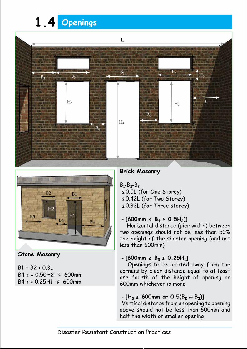
Stone Masonry
B1 + B2 < 0.3LB4 ≥ = 0.50H2 ≮ 600mmB4 ≥ = 0.25H1 ≮ 600mm
Brick Masonry
B1+B2+B3
≤ 0.5L (for One Storey) ≤ 0.42L (for Two Storey) ≤ 0.33L (for Three storey)
- [600mm ≤ B4 ≥ 0.5H2)] Horizontal distance (pier width) between two openings should not be less than 50% the height of the shorter opening (and not less than 600mm)
- [600mm ≤ B5 ≥ 0.25H1] Openings to be located away from the corners by clear distance equal to at least one fourth of the height of opening or 600mm whichever is more
- [H3 ≤ 600mm or 0.5(B2 or B3)] Vertical distance from an opening to opening above should not be less than 600mm and half the width of smaller opening
Disaster Resistant Construction Practices
B1B2
H1H2
B4B4B5
Openings1.4L
B1 B2B3
H3
H2
H1
H2
B4
B4
B5
B5
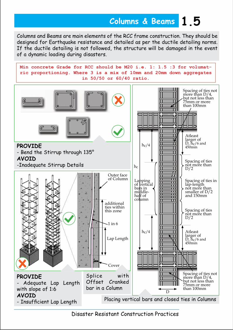
Splice with Offset Cranked bar in a Column
PROVIDE- Bend the Stirrup through 135°AVOID-Inadequate Stirrup Details
PROVIDE- Adequate Lap Length with slope of 1:6AVOID- Insufficient Lap Length
Columns and Beams are main elements of the RCC frame construction. They should be designed for Earthquake resistance and detailed as per the ductile detailing norms. If the ductile detailing is not followed, the structure will be damaged in the event of a dynamic loading during disasters.
Placing vertical bars and closed ties in Columns
Min concrete Grade for RCC should be M20 i.e. 1: 1.5 :3 for volumat-ric proportioning. Where 3 is a mix of 10mm and 20mm down aggregates
in 50/50 or 60/40 ratio.
Disaster Resistant Construction Practices
Columns & Beams 1.5
Outer face of Column
1 in 6
Lap Length
Cover
additional ties within this zone
}}}Spacing of ties in
lap-lengthnot more than smaller of D/2 and 150mm
Spacing of ties not more than D/2
Spacing of ties not more than D/2
D
Spacing of ties not more than D/4, but not less than 75mm or more than 100mm
Spacing of ties not more than D/4, but not less than 75mm or more than 100mm
}Lapping of vertical bars in middle-half of column
Atleast larger of D, hc/6 and 450mmhc/4
hc/4 Atleast larger of D, hc/6 and 450mm
hc

Reinforcement Detail of Beam
Beam bars bent in joint region overstress the core concrete adjoining the bends
A. Reinforcement Detail of Beam-Column Joint at Roof Level
B. Reinforcement Detail of Beam-Column Joint at Floor Level
Disaster Resistant Construction Practices
Column & Beam Junctions
Column should have minimum four 12 diameter bars. It is
preferable to use TMT bars near the coast line.
1.6
}}
2 times depthclosely spaced stirrups ≤ d/4
or db
2 times depthclosely spaced
stirrups}
bottom lapping position
not more than d/2
top lapping position
d
2 times depthclosely spaced
stirrups
bottom lapping position
slab depth
}
2 times depthclosely spaced
stirrups
COLUMN
BEAM
BEAM
COLUMN
BEAM COLUMN BEAM
BEAMCOLUMN
BEAM
d= Depth of Beamdb = Diameter of Bar
BEAM & COLUMN SECTION
BEAMBEAM
COLUMN

Steps Details
A. Stair with Brick StepsB. Stair with RCC Steps
Showing Main Reinforcement OF Stair Supported at Ends of Flights
Staircase 1.7
A B
nosing reinforcementbrick steps
row of chairs
row of chairsLap length
L
150mm
row of chairs
PLfooting
x
x=Greater of 0.15L or Ld
LANDING
reinforcement as per design
Greater of Ld or 0.3L
main steel
dist. steeldist. steel
main steel
150mm
row of chairs
row of chairs
Disaster Resistant Construction Practices

Anchor the vertical tie into the roof slab
Detail for Sun-shade or any cantilever starting from top-edge of the support of the Beam
A, B :
Alternative Details for sunshed or any cantilever slab starting from bottom edge of the support beam
Chair to maintain negative steel in position
L
beam designed for torsional bending
moment
75m
m
Ld
BEAM
CANTILEVER
Disaster Resistant Construction Practices
Cast-in-situ RCC Slab at the support should be reinforced at both top and bottom
Roof band should be provided within the roof-slab
Overhangs and Slabs
A B
Chair
PROVIDEProper weathering course with pressed tile layer to protect RCC Slab.
pressed tile
weathering course
roof slab
100m
m
50d
100m
m
50droof band
CANTILEVERCANTILEVER
BEAM

One-way Slab simply supported on Brickwork without torsional steel.
DD
l
BB
A
A
0.1l
main barsdistribution bars
details of bars along this line
SEC
TIO
N A
A
SPECIFY THICKNESSS
IN PLAN
SECTION BB
PLAN
deta
ils o
f bar
s al
ong
this
line
D
D
A
A
BB lx
ly
0.1lx
0.1ly
Disaster Resistant Construction Practices
Slabs 1.9
Two-way Slab simply supported on Brickwork without torsional steel.
SPECIFY THICKNESSS
IN PLAN
SECTION BB
SEC
TIO
N A
A
distribution bars(2 bars Min.)
Bars in shorter direction shall be placed below bars placed in longer direction
cover(15cm Min.)
PLAN

Disaster Resistant Construction Practices
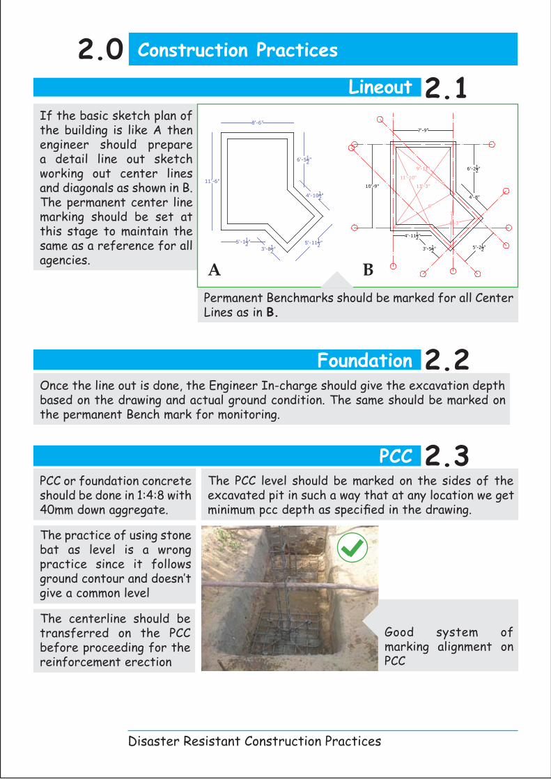
Good quality of concrete in foundation
Footing2.4Footing mat should also have minimum cover of 50mm below and should be installed as per the detail given in section 2.1
While erecting column cage care should be taken so as to start the first link correctly as shown in sketch Starting the first stirrup correctly
Footing Concrete2.5Should be done in line and level as specified in the drawing. The slope of footing is very important and that should be concreted as specified.
Columns are the key structural members for any structure.
It is very important that• Concrete is of good Quality • Columns are properly Aligned.• Dimensional accuracy is maintained
It is a good practice to start the column by first casting the starter for column.
But it is very important that starter concrete quality should be treated with equal seriousness as of main column concrete in terms of quality, alignment and other standard procedures.
Column Starter2.6
Reduction in Grade Beam due to bad formwork
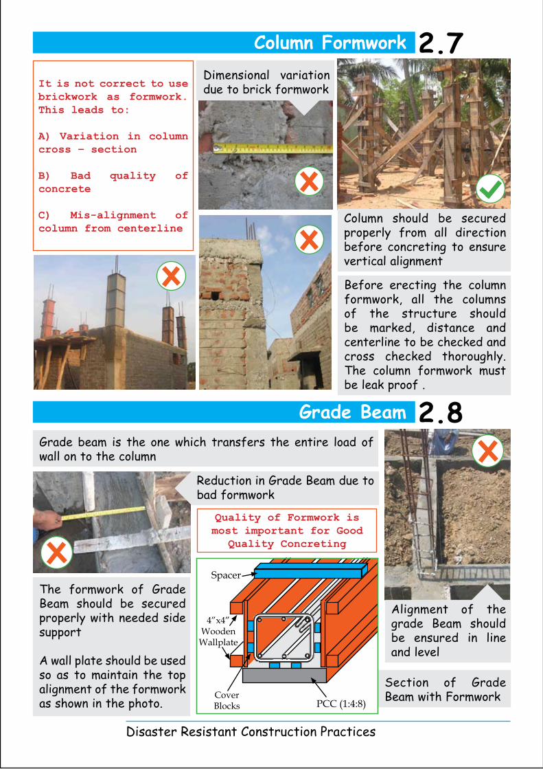
Grade beam is the one which transfers the entire load of wall on to the column
The formwork of Grade Beam should be secured properly with needed side support
A wall plate should be used so as to maintain the top alignment of the formwork as shown in the photo.
Alignment of the grade Beam should be ensured in line and level
Dimensional variation due to brick formwork
Before erecting the column formwork, all the columns of the structure should be marked, distance and centerline to be checked and cross checked thoroughly. The column formwork must be leak proof .
Column should be secured properly from all direction before concreting to ensure vertical alignment
Section of Grade Beam with FormworkPCC (1:4:8)
Spacer
4”x4” Wooden
Wallplate
Cover Blocks
Disaster Resistant Construction Practices
It is not correct to use brickwork as formwork. This leads to:
A) Variation in column cross – section
B) Bad quality of concrete
C) Mis-alignment of column from centerline
Column Formwork 2.7
Quality of Formwork is most important for Good
Quality Concreting
Grade Beam 2.8

Good system of batching
Plank used for walking while concreting
Disaster Resistant Construction Practices
As per IS 456 : 2000 Mininum Grade for any Reinforced concrete construction
is M20. Note that 20N/mm. sq. is not the average strength but is the
characteristic strength.
Concrete is on site manufactured material and hence its quality is highly dependent not only on quality of raw material used but also on methodology and compliances in the batching, mixing, placing and curing of concrete.
Water cement ratio plays a crucial role in the ultimate strength of the concrete. The lower the Water cement ratio, higher the strength.
• M20 in volumetric mix can be achieved by a general proportion of Cement:Sand:Aggregate as 1:1.5:3• For a good quality concrete 3 share of aggregate is to be divided into 10mm and 20mm down jelly. •To ensure quality testing concrete cubes and keeping a record is a must.
Concreting2.9
Cover is one of the most important element of any RCC member. Cover concrete quality is responsible for durability of the concrete and hence ensures the health and long life of RCC members
Cover Blocks Casting : Cover should be cast in the same grade as the slab concrete since it is ultimately a part of slab concrete. It should be cured and treated as importantly as any other insitu RCC member.
Cover block cast with binding wire to be places on vertical face of members like columns and fastened before concreting.
Not ensuring the cover will affect durability of concrete and make it vulnerable to climatic
deteriorations. It can also facilitate the twisting of reinforcement while concreting;
which hampers structural performance.
Nominal cover:Slab : 15mm, Beam : 20 mm, Column : 40mm and Footing : 50mm. The cover may vary depending upon the exposure condition of structure and also fire safety norms required
Cover Concrete2.10
Use of cover blocks and sealant tape in formwork

Brick
- Colour should be reddish brown and Uniform- Edges should be sharp, straight and at right angles to faces- Water absorption should be less than 20% by weight after soaking for 24 Hrs.- The breakage should not exceed 5% of the lot- The brick should not break when dropped on their flat face from a height of 60 cms
Cement
- The date, month and year of manufacture on the bag reveals the freshness of the cement- Silky when rubbed between fingers- When hand is pushed in a cement bag, chillness should be felt. Warmth indicates that hydration has started and cement has aged
The Quantity / Quality of Water
- Never add water without measuring- A marked bucket is the simplest measuring tool- Never use salty water- Water should be potable (drinkable)- pH value should be approximately 7.0
AVOID use inferior Quality of Bricks
Disaster Resistant Construction Practices
Field Tests 2.11
Cement
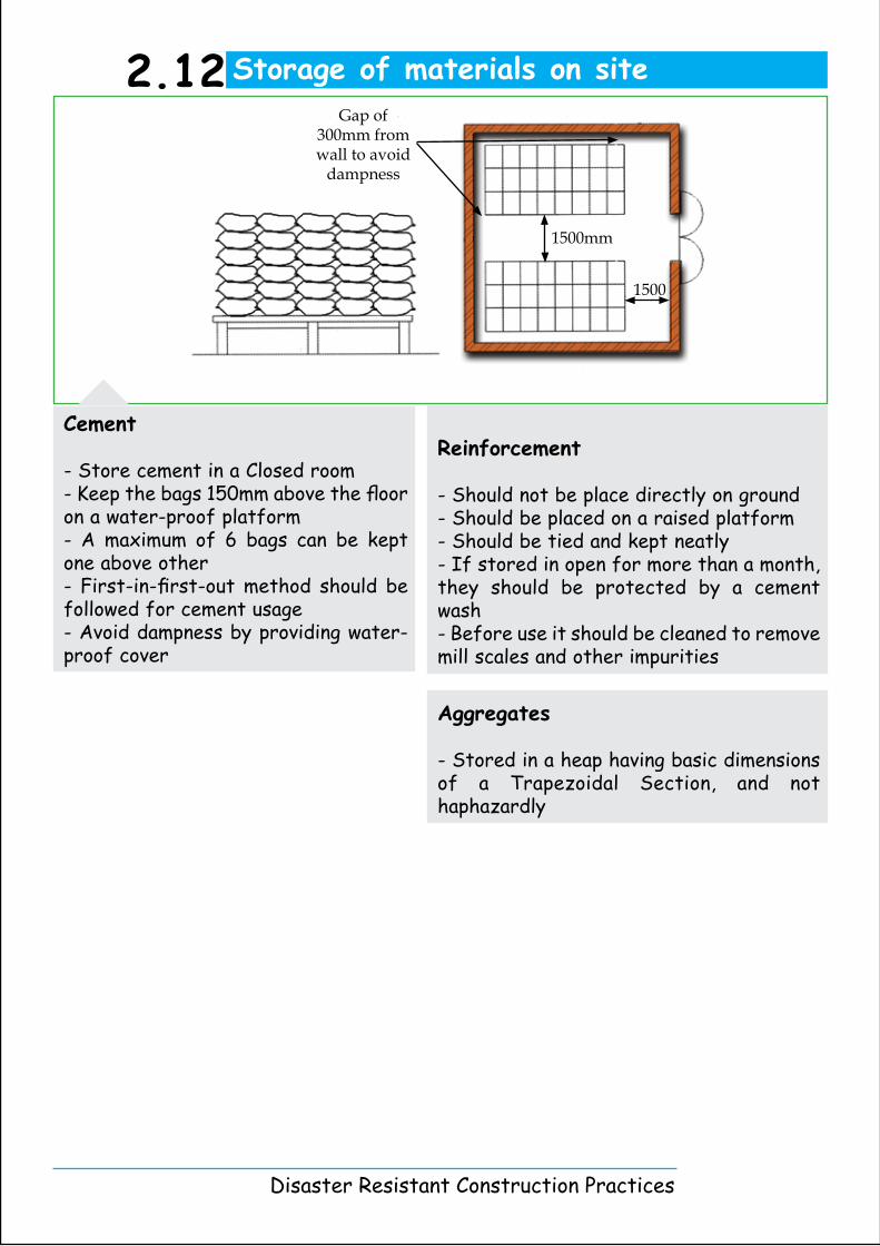
- Store cement in a Closed room- Keep the bags 150mm above the floor on a water-proof platform- A maximum of 6 bags can be kept one above other- First-in-first-out method should be followed for cement usage- Avoid dampness by providing water-proof cover
Reinforcement
- Should not be place directly on ground- Should be placed on a raised platform- Should be tied and kept neatly- If stored in open for more than a month, they should be protected by a cement wash - Before use it should be cleaned to remove mill scales and other impurities
Aggregates
- Stored in a heap having basic dimensions of a Trapezoidal Section, and not haphazardly
Disaster Resistant Construction Practices
Storage of materials on site2.12
1500mm
1500
Gap of 300mm from wall to avoid
dampness
Disaster Resistant Construction Practices
4.0 Appendices
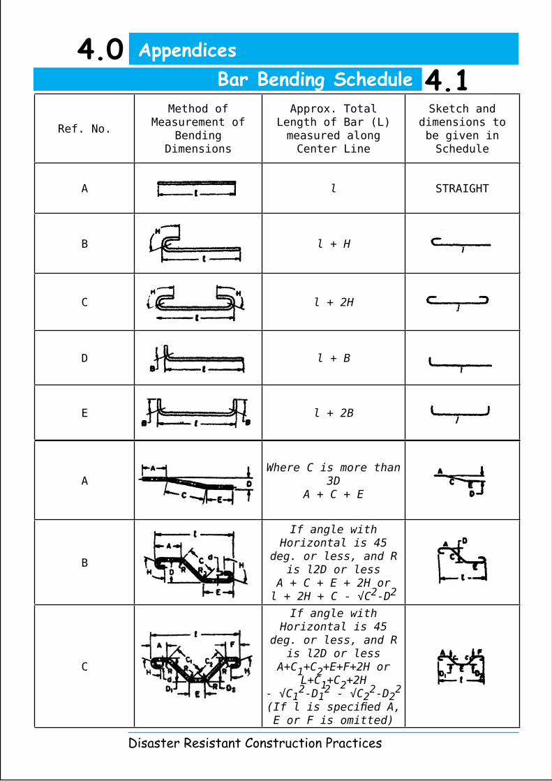
Ref. No.
Method of Measurement of
Bending Dimensions
Approx. Total Length of Bar (L) measured along Center Line
Sketch and dimensions to be given in Schedule
A l STRAIGHT
B l + H
C l + 2H
D l + B
E l + 2B
AWhere C is more than
3DA + C + E
B
If angle with Horizontal is 45
deg. or less, and R is l2D or less
A + C + E + 2H orl + 2H + C - √C2-D2
C
If angle with Horizontal is 45
deg. or less, and R is l2D or less
A+C1+C2+E+F+2H orL+C1+C2+2H
- √C12-D1
2 - √C22-D2
2
(If l is specified A, E or F is omitted)
Bar Bending Schedule 4.1
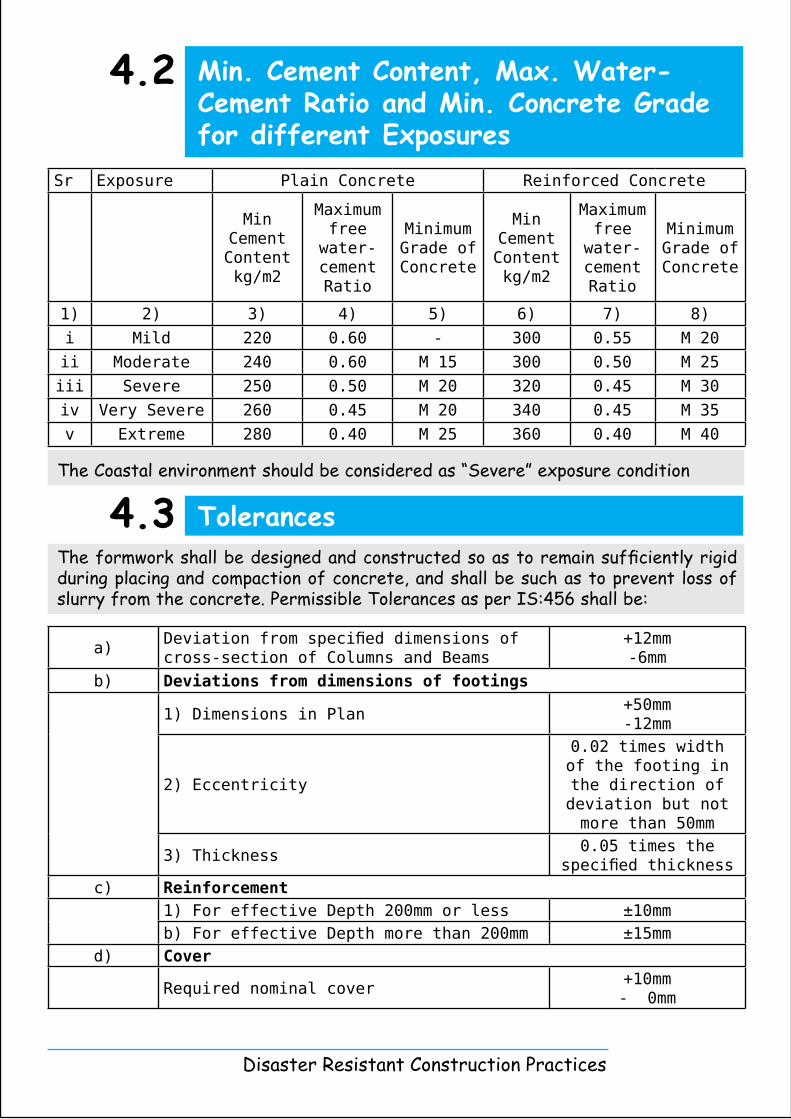
The formwork shall be designed and constructed so as to remain sufficiently rigid during placing and compaction of concrete, and shall be such as to prevent loss of slurry from the concrete. Permissible Tolerances as per IS:456 shall be:
a)Deviation from specified dimensions of cross-section of Columns and Beams
+12mm-6mm
b) Deviations from dimensions of footings
1) Dimensions in Plan+50mm-12mm
2) Eccentricity
0.02 times width of the footing in the direction of deviation but not more than 50mm
3) Thickness0.05 times the
specified thicknessc) Reinforcement
1) For effective Depth 200mm or less ±10mmb) For effective Depth more than 200mm ±15mm
d) Cover
Required nominal cover+10mm- 0mm
The Coastal environment should be considered as “Severe” exposure condition
Disaster Resistant Construction Practices
Min. Cement Content, Max. Water-Cement Ratio and Min. Concrete Grade for different Exposures
4.2
Sr Exposure Plain Concrete Reinforced Concrete
Min Cement Content kg/m2
Maximum free
water-cement Ratio
Minimum Grade of Concrete
Min Cement Content kg/m2
Maximum free
water-cement Ratio
Minimum Grade of Concrete
1) 2) 3) 4) 5) 6) 7) 8)
i Mild 220 0.60 - 300 0.55 M 20
ii Moderate 240 0.60 M 15 300 0.50 M 25
iii Severe 250 0.50 M 20 320 0.45 M 30
iv Very Severe 260 0.45 M 20 340 0.45 M 35
v Extreme 280 0.40 M 25 360 0.40 M 40
Tolerances4.3

This Handbook has been prepared for the benefit of technical supervisors and masons as a part of Information Education and Communication Campaign in the post Tsunami shelter reconstruction. This is a joint initiative of Government of Tamil Nadu and UNDP. This handbook is prepared with technical assistance from Society for Environment Protection (SEP) and Orissa Development Technocrat Forum (ODTF) under the guidance of Prof. A. R. Santhakumar.
Contact :Er. Alok Patnaik, Project Officer, Shelter and Habitat, UNDP E-mail : [email protected]
UNDP, United Nations team for Tsunami Recovery Support,Apex Towers, 54, 2nd Main Road, RA Puram, Chennai – 600 028Tel : +91 4442 303 551Website :www.un.org.in/untrs
Flyash Brick MasonryFlorida Construction-UNDP
Compressed Stabilized Earth Block Auroville Earth Institute and UNDP
Rat – Trap Masonry COSTFORD and UNDP Hands on Mason Training
Office of the Special Commissioner and Commissioner for Revenue Administration,
Disaster Management & Mitigation Department, Chepauk, Chennai 600 005; Email : [email protected]; Website : www.tn.gov.in/tsunami
Sep 07
Retrofitting technology demonstration unitby SEP and UNDP