
a comparison of discrete cosine transform and discrete wavelet transform algorithm in

A Recognition Algorithm of VGPO Jamming Basedon Discrete Chirp-Fourier TransformChuanzhang Wu
Xidian UniversityBaixiao Chen ( [email protected] )
Xidian University https://orcid.org/0000-0001-7320-327X
Research
Keywords: Deceptive jamming, Discrete chirp-Fourier transform, Jamming recognition, Feature extraction
Posted Date: June 24th, 2020
DOI: https://doi.org/10.21203/rs.3.rs-21374/v2
License: This work is licensed under a Creative Commons Attribution 4.0 International License. Read Full License
Version of Record: A version of this preprint was published on August 17th, 2020. See the publishedversion at https://doi.org/10.1186/s13634-020-00694-3.
Wu and Chen
RESEARCH
A Recognition Algorithm of VGPO JammingBased on Discrete Chirp-Fourier TransformChuanzhang Wu and Baixiao Chen*
Abstract
This paper addresses the recognition problem of velocity gate pull-off (VGPO) jamming from the target echosignal for the velocity-based tracking system. The discrete chirp-Fourier transform (DCFT) is studied in thispaper to jointly estimate the chirp rates and frequencies of the target and jamming signals. Firstly, the scalingcharacteristic of the DCFT algorithm is explored. Then we focus on the quantitative effect of the VGPOjamming signal by analyzing the jointly estimated results in each pulse. The quantitative effect indicates that,as long as the estimated frequency is unchanged, the relationship between the estimated chirp rate and thepulse numbers is similar to the relationship between the frequency offset of VGPO jamming and the time.Finally, by utilizing the joint estimated results in each pulse repetition interval and calculating the mean squareto variance ratio (MSVR) of the normalized estimated chirp rate, the VGPO jamming can be recognized.Simulation results show that the jamming signal and the target echo become distinguishable with the proposedfeature. Comparing to the existing works, the proposed method can correctly recognize the jamming signalwith lower jamming-to-noise ratio (JNR) 5dB with less data needed, which means it can work effectively in theearly stage of interference implementation and shows great potential in practical applications.
Keywords: Deceptive jamming; Discrete chirp-Fourier transform; Jamming recognition; Feature extraction
1 IntroductionElectronic countermeasure (ECM) has always been animportant research direction in radar [1, 2]. As a typ-ical category, the deceptive jamming is often used todeceive a hostile radar system by generating a largenumber of active false targets in terms of direction,position, and velocity [3]. With the widespread appli-cation of the digital radio frequency memory (DRFM)technique, the interference effect of ECM is furtherreinforced. In a DRFM system, the intercepted radarsignal is firstly down-shifted in frequency. And thenit is sampled with an analog-to-digital converter andstored in a high-speed digital memory where the sam-ples can be manipulated in amplitude, frequency, andphase to produce desired deceptive signals. When be-ing recalled, the stored samples are processed by adigital-to-analog converter, and then transmitted backto the victim radar [4].Over several decades, with the continuous develop-
ment of ECM, the electronic counter-countermeasures(ECCM) are also studied by more and more researcher-
*Correspondence: [email protected]
National Laboratory of Radar Signal Processing, Xidian University, Taibai
South Road, 710071, Xi’an, China
Full list of author information is available at the end of the article
s. Many methods for recognizing and countering decep-tive jamming are studied based on the DRFM tech-nique. In 2006, Maria analyzed the phase and delayquantization effect of the DRFM device in detail [5].In [6], she further defined the difference between thedeceptive jamming and the target echo in the frequen-cy domain as the jamming signal error angle whichis introduced by the DRFM system and proposed adetection method.Furthermore, many researchers counter the jamming
signal from the aspect of jamming detection. In [7], theauthors presented the adaptive detection schemes andthe enhanced adaptive sidelobe blanking algorithms,which consider the scenario in realistic when a mis-matched signal is present in the data. In [8], they pro-posed an new algorithm to detect the coherent signalsfrom noise, clutter and noise-like interference. For thesame problem, two dataset are utilized at the designstage to get receiver adaption, and a two-stage detec-tor is recommended [9]. In [10], the authors conceiveda multiple-stage adaptive architectures to detect thetarget, and shows a better performance compared tothe two-stage detector in [9].What’s more, the jamming signal can also be distin-
guished from the target according to their difference

Wu and Chen Page 2 of 10
in various domains. In [11], the authors found the d-ifference between the deceptive jamming and the tar-get echo by calculating their product spectrum ma-trix. In [12], the deceptive jamming is analyzed inthe spatial frequency domain in the multiple-inputmultiple-output system with frequency diverse arrayand suppressed in the joint transmit-receive domain.Moreover, the deceptive jamming and its anti-jammingmethods in some new radar systems are also studied[13, 14].Although the range gate-pull off (RGPO) in DRFM
devices has been studied by many researchers [15, 5],not many published literature on the velocity gate pull-off (VGPO) jamming about the recognition and coun-tering problem are available. In [16], the authors pro-posed an approach to suppress the velocity deceptionjamming by designing adaptive initial phases in thepulse repetition interval (PRI) domain. This methodis further applied in the cognitive radar system [17]. In[18], a VGPO jamming countermeasure is proposed byutilizing the front-back-edge tracking gate, while it hasto judge the jamming pulling off direction first. Thesemethods are based on waveform design and radar sys-tems respectively. By drawing on the texture feature inimage recognition, Yang converted the time-frequencyimage of the jamming signal into a gray image, andthen extracted the image feature based on the Zernikemoments and recognize the jamming signal [19]. Al-though this method can recognize various jamming sig-nals in a single pulse, it requires that there are somedistinct differences in the time-frequency domain a-mong various kinds of jamming signals. In other word-s, it can only be effective after the pull-off jamminghas been implemented for a long time.The purpose of this paper is to approach a recog-
nition algorithm towards the VGPO jamming. Tothis end, the joint estimation algorithm of the chirprate and frequency is introduced. Different from themethod in [19], we analyze the theoretical estimationresults of chirp rate and frequency in each pulse, andthen extract the feature about the estimated chirp rateto distinguish the VGPO jamming and target.Currently, many methods are available on joint es-
timation, such as maximum-likelihood [20], adaptivechirplet transform [21] and phase function [22]. Howev-er, the theoretical value of the rate of frequency of thejamming signal is far less than the minimum interval inthe chirp rate domain in a general way. Consequently,most of these methods will lose efficacy. For the dis-crete chirp-Fourier transform (DCFT) algorithm[23],it is generalized from the discrete Fourier transform(DFT). Besides matching the multiple frequency sim-ilar to the DFT algorithm, it uses the multiple chirpcomponents to match the chirp rates. Most important
of all, it can increase the resolution in the chirp rate do-main by introducing a scaling factor, which is termedas the scaling property and will be analyzed in this pa-per. As a result, it is still applicable in this situation.Nowadays, it has applied in many cases [24, 25].This paper is organized as follows. In Section 2, the
received signal models of both real target echo and VG-PO jamming are first formulated, then we introducethe modified DCFT and analyze its scaling property,and derive the estimated chirp rate and frequency ineach pulse repetition interval (PRI), and further definea new feature parameter. Section 3 shows the simula-tion results. Section 4 is the concluding remarks.
2 MethodsIn this section, we elaborate on the theory andthe method of jamming signal recognition. First, wepresent the signal models for VGPO jamming and tar-get echo. Second, we introduce the modified DCFTand study its scaling property. Then, the quantitativeeffect is analyzed when performing the joint estimationwith the DCFT algorithm, and it is also discussed inthe non-linear scenario. Finally, we define a feature todistinguish the VGPO jamming and the target echo.
2.1 Signal ModelThe whole process that a jammer implements VGPOinterference can be divided into three steps: pull-offhalting, pulling off, and closing [3]. After the radarsignal is intercepted, the jammer retransmits the signalwith a Doppler frequency shift inflicted on. To deceivethe radar effectively, the power of the jamming signalis always greater than that of the real target echo.Therefore, the tracking loop of the radar would trackthe false Doppler frequency, and be slowly pulled awayfrom the velocity gate of the real target.Assume the signal transmitted by radar is s(t). Then
the signal reflected by a hypothetical target in the far-field can be modeled as [16]
sr(t) = Ars(t− tr)ej2πfd(t−tr) + n(t) (1)
where Ar and tr denote the reflection coefficient andthe time delay of the hypothetical target respectively,and fd is its Doppler frequency.Comparing with the real target echo, the VGPO jam-
ming has a pseudo-Doppler frequency shift based onfd. For convenience, we consider the scenario that on-ly one interference exits, and the jamming signal canbe expressed as
sJ(t) = AJs(t− tJ)ej2πfdj(t−tJ ) + n(t) (2)
where AJ denotes the equivalent reflection coefficientof the interfering source, tJ = tr +∆td is the jamming
Wu and Chen Page 3 of 10
propagation delay, and ∆td is the time delay of jammerrelay which is often far less than tr, fdj = fd +∆fd isthe modulated pseudo-Doppler frequency. Here, we de-fine jamming-to-noise ratio (JNR) A2
J/σ2, and signal-
to-noise ratio (SNR) A2r/σ
2, where σ2 is the variance ofGaussian noise n(t), and jamming-to-signal ratio (JS-R) is defined as JNR-SNR.Similar to the RGPO system described in [5, 26],
a VGPO system should linearly increase the frequen-cy offset to create a series of constant velocity-ratefalse targets. This scenario is also the one we often usewhen analyzing VGPO [19, 27, 28], and is equivalentto the constant acceleration profile in the range do-main. Then the fdj at the mth PRI can be expressedas [28]:
fdj = Vf [t+ (m− 1)Tr] + fd (3)
where Vf denotes the slope of fd with respect to twhich is also called acceleration, Tr denotes the pulserepetition period.To enable radar accurately capture and track the ve-
locity loop of the jamming signal, Vf won’t be greaterthan the maximum trackable acceleration of a targetto radar [1]. On the other side, Vf won’t be partic-ularly small for implementing interference effectivelyand protecting the real target. In a word, Vf has areasonable value range.Substitute (3) into (2), and we can find that, despite
the signal form, the VGPO jamming signal is a chirpfunction with a chirp rate of Vf . This is the inspirationfor the jamming identification in this paper.As the specific form of s(t) is not assumed, we may
have to do some preprocessing to prevent the influenceof the potential time-varying frequency components insignal form on chirp rate estimation. The preprocess-ing may be different for various kinds of signals. Takethe widely used linear frequency modulation (LFM)signal as an example, it has a quadratic term in termsof t, i.e., the inherent chirp rate. Generally speaking,the acceleration Vf of the VGPO jamming (three timesthe acceleration of gravity in X-band is about 2kHz/s)is much smaller than the chirp rate of LFM signal (typ-ical value 1010 − 1014 Hz/s, [1]). As a result, the de-chirping processing should be performed first in therecognition procedure for the radar that emits LFMsignal.After being sampled with discrete-time t = nTs
where Ts denotes the sampling interval, and perform-ing some appropriate preprocessing, the jamming sig-nal s′J(t) in mth PRI can be expressed as
sJ(n) = s′J(t)∣
∣
∣
t=nTs
= AJexp{j2π(Vfn2T 2
s + f ′
djnTs) + jϕj},(4)
where
f ′
dj = fd + (m− 1)VfTr − Vf tJ + fd0, (5)
ϕj = −2π(fd + (m− 1)VfTr)tJ + ϕ0, (6)
where fd0 and ϕ0 separately denote the time-invariantfrequency and constant phase term in sJ(n).The phase of the discretized jamming signal in (4)
contains three components, a quadratic item with re-spect to nTs with a coefficient Vf , a linear item withrespect to nTs with a coefficient f ′
dj and a time-independent item ϕj . Ignoring the time-independentphase item, the coefficient f ′
dj of the linear item is d-ifferent in various PRIs, while the coefficient of thequadratic phase items are the same. However, the fol-lowing analysis indicates that the quantization in thefrequency domain will influence the estimated resultin the chirp rate domain when performing joint esti-mation to the jamming signal.
2.2 Discrete Chirp-Fourier Transform and its ScalingProperty
The discrete chirp-Fourier transform algorithm is usedto jointly estimate the chirp rate and the frequency ofa chirp-type signal. For an analog chirp signal x(t) =exp[j2π(k0t+l0t
2)] (0 ≤ k0, l0 ≤ N−1), its discretizedform with sample rate 1/N is
xI(n) = W−(k0n+l0n
2/N)N (7)
where WN = exp(−j2π/N). The corresponding N -point DCFT of signal xI(n) is defined as [29]
Xc(k, l) =1√N
N−1∑
n=0
xI(n)Wkn+ln2/NN , 0 ≤ k, l ≤ N−1
(8)
where k and l represent the frequency and chirp ratevariable respectively.In (7), the duration of the signal is normalized as
1, which makes both of k and l are less equal thanthe length of signal N . In radar signal processing, theDoppler frequency of the signal is less than the sam-pling frequency of fs, and the chirp rate is less thanf2s correspondingly. After sampling with discrete-timet = nTs, the discretized form of x(t) is rewritten as
x(n) = exp[j2π(k0nTs + l0n2T 2
s )] (9)
where 0 ≤ k0 < fs, 0 ≤ l0 < f2s . To maintain the
consistency between the estimated values of frequency
Wu and Chen Page 4 of 10
and chirp rate and the actual ones, the correspondingform of DCFT should be modified as
Xmc(k, l) =1√N
N−1∑
n=0
x(n)W kn+ln2
N , 0 ≤ k, l ≤ N−1
(10)
Each bin in frequency domain and chirp rate do-main represents fs/N and f2
s /N respectively. When|Xmc(k, l)| maximizes, the estimated values of k and lare
k = k0NTs, l = l0NT 2s (11)
respectively, and the corresponding estimated valuesof frequency and chirp rate are k0 and l0 respectively.Essentially, the time delay of a signal is equivalent
to zero-padding in front of the signal. It changes thephase of the signal’s DFT result, while the estimat-ed frequency and the envelope of DFT results are un-changed. In a very short timestamp, the positions oftarget and jammer are usually considered to be locatedin the same range cell. Under this assumption, both ofthe time delay tr and tJ are constant, which means thenumber of zero paddings in each PRI is the same dur-ing this period. In other words, the time delay in thesePRIs won’t influence the estimated value of frequencythrough DFT. As the DCFT algorithm is a generalizedform of the DFT algorithm, this conclusion is applica-ble for jointly estimating the values of chirp rate andfrequency with the DCFT algorithm.From (10), one can see that the chirp rate variable
only appears in the factor W ln2
N . It means that thechirp rate domain of DCFT can be broadened or com-pressed after dividing the variable l by a scaling factorC, which equivalently increases or decreases the mini-mum interval in the chirp rate axis. According to thescalability of the DCFT algorithm in the chirp rate do-main, we further define the modified DCFT as follows
X ′
mc(k, l) =1√N
N−1∑
n=0
x(n)Wkn+ln2/CN (12)
At this time, the maximum value in the chirp rateaxis changes from f2
s to f2s /C, and the corresponding
minimum interval decreases to f2s /NC. Similarly, for
the chirp signal in (9), the peak position in the modi-fied DCFT domain is located at
k = k0NTs, l = l0NCT 2s , (13)
and the corresponding values of frequency and chirprate are k0 and l0 respectively. It indicates that the
estimated values of chirp rate and frequency are un-changed in the modified DCFT compared with the D-CFT in (10).As mentioned above, the value of Vf is in a rea-
sonable range. What’s more, the sampling frequencyfs is always known as prior information. As a result,the scaling factor C has a rough estimation for theradar side. The bigger the scaling factor C, the small-er the minimum interval in the chirp rate domain forthe modified DCFT algorithm. In fact, if C is big e-nough or much bigger than N , the DCFT result fordifferent l is almost the same. In this case, the DCFTalgorithm is considered as degenerating into the DFTalgorithm and could cause a huge estimation error tothe chirp rate at low SNR.
2.3 The Analysis of Quantitative EffectIn this part, we analyze the influence of a small fre-quency offset on the DCFT estimation results. In theDFT algorithm, we estimate the constant frequencyfn0 of a signal by matching it with a quantitative val-ue in frequency domain, i.e., fn0 = n0fs/N , whereN isthe total number of DFT, n0(0 ≤ n0 < N−1) is a cer-tain nonnegative integer. When the signal’s frequencyfn1 has an offset ∆f based on fn0, i.e.,
fn1 = fn0 +∆f, (14)
the peak still exhibits at the position f = fn0 onlyif |∆f | < fs/2N . It means the frequency offset ∆fis ignored due to the quantization in the frequencydomain.Similarly, the quantization error must occur in the
DCFT algorithm as well. From [23], it is pointed outthat, for a discrete chirp signal
x̃(n) = W−(k̃0n+l̃0n
2)N , (15)
its DCFT result has the similar peak property as the
signal x(n) = W−(k0n+l0n
2)N , where k̃0 and l̃0 close to
integers l0 and k0 respectively, i.e.
|l̃0 − l0| < ǫ and |k̃0 − k0| < η (16)
where ǫ and η are two arbitrary positive values. Howev-er, this conclusion is drawn based on the condition thatl̃0 and k̃0 are close enough to l0 and k0, i.e., ǫ, η ≈ 0.As the process of pulling off a velocity gate is contin-uous, the pseudo Doppler frequency of the jammingsignal changes in each PRI. Moreover, the minimuminterval in the chirp rate axis decreases after adoptingthe modified DCFT in (12). As a result, it becomesvery necessary to analyze the quantitative effect of theDCFT algorithm in this paper.

Wu and Chen Page 5 of 10
For a discrete VGPO jamming in (4), its modifiedDCFT after ignoring the time-independent phase itemϕj can be calculated by
X ′
mc(k, l) =1√N
N−1∑
n=0
sJ(n)Wkn+ln2/CN
=AJ√N
N−1∑
n=0
ej2π(Vfn2T 2
s +f ′
djnTs−kn/N−ln2/NC)
(17)
Let the Doppler frequency
f ′
dj = f̃dj +∆fm (18)
where f̃dj is an integer multiple of fs/NC, and ∆fmdenotes the remainder Doppler frequency besides f̃dj inmth PRI. Here, we assume the total number of pulsesis M when the estimated frequency through the modi-fied DCFT is fixed as f̃dj . Then we have 0 ≤ m ≤ M−1and 0 ≤ ∆fm < ∆fM < fs/NC.
For the convenience of representation, we let f̃dj =fd − Vf (Tr + tJ) + fd0, and ∆fm = mVfTr accordingto (5) and (18). Then (17) can be rewritten as follows
X ′
mc(k, l) =AJ√N
N−1∑
n=0
ej2πφ1ej2πφ2 , (19)
where φ1(n) = (VfT2s − l
NC )n2 + mnVfTrTs and
φ2(n) = (f̃djTs − k/N)n.
Let
P =
∣
∣
∣
∣
∣
N−1∑
n=0
ej2πφ1ej2πφ2
∣
∣
∣
∣
∣
. (20)
In the complex coordinates system, each complex ex-ponential can be regarded as a unit vector. Conse-quently, P can be considered as the modulus of a vec-tor summed by N unit vectors, and it reaches to max-imum of N when all of the vectors point in the samedirection. According to [23], P maximizes when the fre-quency variation of DCFT matches to the quantizedfrequency f̃dj , i.e. φ2 = 0. Then we have
k = Nf̃dj/fs (21)
On the other side, φ1(n) differs by an integer to var-ious n,
φ1(n1) = φ1(n2) + ϕ0n (22)
where n1 and n2 are two arbitrary different integersbetween 0 and N − 1, ϕ0n is an integer. Substitutingthe expression of φ1 into (22), we can yield
(VfT2s − l
NC)(n1+n2)+mVfTrTs =
ϕ0n
n1 − n2(23)
Let α1 = ϕ0n/(n1 − n2), and α2 = n1 + n2. Then, ifP reaches to maximum N , it implies that the variablel to arbitrary n1 and n2 in (23) is solvable, i.e.,
l = NC(VfT2s +
mVfTrTs − α1
α2) (24)
The effective value of φ1 only exists in the fractionalpart from 0 to 1 due to the periodicity of the expo-nential function. Correspondingly, the true value of lis the remainder after dividing by N in (24). In oth-er words, for a fixed m, the true value of l should befixed, too.From (24), one can see that l and m are linearly re-
lated. In general, not all vectors in (20) point in thesame direction, and P can not reach to maximum N .ϕ0n in (22) is not an integer anymore to a fixed pair ofintegers n1 and n2, which changes the estimated chirprate of jamming signal in mth PRI. Among variousPRIs, m is the unique determining factor that influ-ences the value P , and the estimated chirp rate l. Fromthis point, ϕ0n is not an integer either for various pairsof n1 and n2. However, it can be found from the for-mulation of φ1 that, ϕ0n is linearly related to m forfixed n1 and n2. It means l is still proportional to m.As
mnVfTrTs = nTs∆fm <n
NC≤ n2
NC, (25)
the influence of m to φ1(n) and l is small. Once Vf isfixed, all integer pairs n1 and n2 that makes P reach tothe maximum value (not N) are basically determined.Therefore, the slope between l andm can be consideredto be unchanged at this time.More generally, ∆f includes an extra frequency in-
dependent of m (part of f̃dj) which results in ϕ0n isnot an integer either. Then the estimated chirp rate ofVGPO jamming in mth PRI may differ form the onein (24), while the linear relationship between l and mstill exists.It can be seen that, when a joint estimation of the
VGPO jamming with the DCFT algorithm is per-formed, the quantization in frequency domain will af-fect the estimated value of the chirp rate, and the es-timated chirp rate is linearly related to the residue ofthe quantized frequency item.
Wu and Chen Page 6 of 10
Unlike in (3), we next discuss a more general scenariothat the false target is maneuvering, which means fdjhas a non-linear correlation with time t. Taking thequadratic relation as an example, fdj changes as fol-lows over time t:
fdqj = Af [t+(m−1)Tr]2+Vf [t+(m−1)Tr]+fd, (26)
where Af is the cubic coefficient of time t.Substituting the fdj in (2) with fdqj , and following
the same derivation from (4)∼6 and (17)∼(19), we cancalculate the modified DCFT of the jamming signal innon-linear scenario. Similar to (5), the frequency itemof the preprocessed jamming signal f ′
dqj can be ex-pressed as follows
f ′
dqj = Afn2T 2
s + [Vf + 2Af (m− 1)Tr −Af tJ ]nTs
+∆f ′
m + fd − Vf tJ
(27)
where
∆f ′
m = Af (m−1)2T 2r +(Vf −2Af tJ)(m−1)Tr (28)
Still, we let φ′
1(n) be the function that includes highorder terms of n and ∆f ′
m, i.e.,
φ′
1(n) =Afn3T 3
s + [Vf + 2(m− 1)AfTr]n2T 2
s
+∆f ′
mnTs − ln2/NC.(29)
Obviously, besides a cubic item of nTs, there is aquadratic item of n with respect to m, and a lin-ear item of n with respect to m2 in φ′
1(n). With thesame condition as in (22), we can find that there is aquadratic relation between l and m in this situation.More generally, the relationship between l and m issame with that between fdj and t. Here, we term thisphenomenon as a quantitative effect.Therefore, it can be concluded that, a series of small
offsets in frequency would increase the values of thechirp rate in joint estimation. The quantitative effectcan be interpreted as, within the timestamp when theestimated quantized frequency is unchanged, the esti-mated chirp rate of the VGPO jamming through themodified DCFT algorithm increases with a tendencythat is the same as the relationship between fdj and t.
2.4 Feature ExtractionIn this part, we use an identification parameter tobenchmark the quantitative effect. As the pull-off stageof VGPO jamming continues for several seconds [1],the quantitative effect will appear periodically. For thereal target echo, the estimated chirp rate through the
modified DCFT algorithm is essentially the estimationerror caused by thermal noise. Its value equals 0 in anideal case, and randomly changes under noisy environ-ment. By utilizing the distinctive quantitative effect,the VGPO jamming can be distinguished from the realtarget echo.Here, we define the feature, the mean square to vari-
ance ratio (MSVR) of the normalized estimated chirprate, and utilize it to distinguish the VGPO jammingand the real target echo. Let Ce(m) represent the esti-mated chirp rate in mth PRI, and its normalized formis yield by
C ′
e(m) =Ce(m)− Cmin
e
Cmaxe − Cmin
e
(30)
where Cmaxe and Cmin
e represent the maximum andminimum of Ce, respectively.Let C′
e = [C ′
e(1) C′
e(2) · · ·C ′
e(m)], and the MSVR isdefined as
MSVR =µ2c
σ2c
(31)
where µc and σc stand for the mean and the varianceof C′
e respectively.From the aforementioned content, it is concluded
that Ce(m) of VGPO jamming linearly (or nonlinear-ly) increases in M PRIs. Although the estimated chirprate is normalized from 0 to 1, its variance becomessmaller and smaller as the JNR increases. On the con-trary, all of the elements in Ce of real target echocan be regarded as random, which means its MSVR issteady. Consequently, the VGPO jamming signal andthe real target echo can be recognized by setting aproper threshold.The flowchart of the identification procedure to VG-
PO jamming based on the DCFT algorithm is providedin Fig. 1. After being sampled, the received signal ispreprocessed. Then the chirp rate of the signal is es-timated by the modified DCFT in each pulse. Finally,by calculating the value of MSVR with the estimatedresults in M PRIs, the VGPO jamming can be identi-fied from the target signal.
3 Results and DiscussionIn this section, we conduct some simulation experi-ments to illustrate the performance of the proposedmethod in this article. We assume the waveform of thetransmitted signal is LFM. It is worth noting that thepulse numbers is set relatively large in some simula-tions which is similar with [18]. This is because ourmethod is performed from the time when the interfer-ence begins to implement, and the shifted frequencyis small at the early pull-off stage and even within asingle frequency interval.
Wu and Chen Page 7 of 10
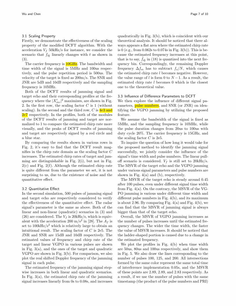
3.1 Scaling PropertyFirstly, we demonstrate the effectiveness of the scalingproperty of the modified DCFT algorithm. With theacceleration Vf 50kHz/s for instance, we consider thescenario that fdj linearly changes with t as shown in(3).The carrier frequency is 10GHz. The bandwidth and
time width of the signal is 5MHz and 100us respec-tively, and the pulse repetition period is 500us. Thevelocity of the target is fixed as 200m/s. The SNR andJNR are 5dB and 10dB respectively and the samplingfrequency is 10MHz.Both of the DCFT results of jamming signal and
target echo and their corresponding profiles at the fre-quency where the |X ′
mc|2 maximizes, are shown in Fig.2. In the first row, the scaling factor C is 1 (withoutscaling). In the second and the third row, C is 4e3 and2e7 respectively. In the profiles, both of the modulesof the DCFT results of jamming and target are nor-malized to 1 to compare the estimated chirp rate morevisually, and the peaks of DCFT results of jammingand target are respectively signed by a red circle anda blue star.By comparing the results shown in various rows in
Fig. 2, it’s easy to find that the DCFT result mag-nifies in the chirp rate domain as the scaling factor Cincreases. The estimated chirp rates of target and jam-ming are distinguishable in Fig. 2(i), but not in Fig.2(c) and Fig. 2(f). Although the estimated chirp rateis quite different from the parameter we set, it is notsurprising to us, due to the existence of noise and thequantitative effect.
3.2 Quantitative EffectIn the second simulation, 500 pulses of jamming signaland target echo are respectively considered to verifythe effectiveness of the quantitative effect. The radarsignal’s parameter is the same as above. Both of thelinear and non-linear (quadratic) scenarios in (3) and(26) are considered. The Vf is 20kHz/s, which is equiv-alent with the acceleration 200 m/s2 in [28]. The Af isset to 100kHz/s2 which is relatively large to obtain anintuitional result. The scaling factor of C is 2e5. TheJNR and SNR are 15dB and 10dB respectively. Theestimated values of frequency and chirp rate of thetarget and linear VGPO in various pulses are shownin Fig. 3(a), and the ones of the target and quadraticVGPO are shown in Fig. 3(b). For comparison, we alsoplot the real shifted Doppler frequency of the jammingsignal in each pulse.The estimated frequency of the jamming signal step-
wise increases in both linear and quadratic scenarios.In Fig. 3(a), the estimated chirp rate of the jammingsignal increases linearly from 0s to 0.08s, and increases
quadratically in Fig. 3(b), which is coincident with ourtheoretical analysis. It should be noticed that there al-ways appears a flat area where the estimated chirp rateis 0 (e.g., from 0.062s to 0.074s in Fig. 3(b)). This is be-cause the estimated frequency increases at this point,that is to say, f̃dj in (18) is quantized into the next fre-quency bin. Correspondingly, the remaining Dopplerfrequency ∆fm has to subtract fs/N , which causesthe estimated chirp rate l becomes negative. However,the value range of l is form 0 to N −1. As a result, theestimated chirp rate l becomes 0 which is the closestone to the theoretical value.
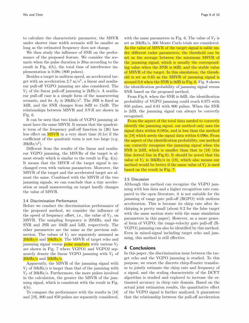
3.3 Influence of Difference Parameters to DCFTWe then explore the influence of different signal pa-rameters, pulse numbers, and SNR (or JNR) on iden-tifying the VGPO jamming by utilizing the proposedfeature.We assume the bandwidth of the signal is fixed as
5MHz, and the sampling frequency is 10MHz, whilethe pulse duration changes from 20us to 100us withduty cycle 20%. The carrier frequency is 15GHz, andthe scaling factor C is 2e5.To inquire the question of how long it would take for
the proposed method to identify the jamming signalsuccessfully, we jointly consider the influence of thesignal’s time width and pulse numbers. The linear pull-off scenario is considered. Vf is still set to 20kHz/s.The MSVR of the target echo and the VGPO jammingunder various signal parameters and pulse numbers areshown in Fig. 4(a) and (b), respectively.The MSVR of the target echo is steady around 0.45
after 100 pulses, even under different signal time widthfrom Fig. 4(a). On the contrary, the MSVR of the VG-PO jamming is various under different time width anddifferent pulse numbers in Fig. 4(b), and its maximumis about 2.96. By comparing Fig. 4(a) and Fig. 4(b), wecan find that the MSVR of jamming signal is alwaysbigger than that of the target echo.Overall, the MSVR of VGPO jamming increases as
the number of pulses increases until the estimated fre-quency changes. The wider the time width, the fasterthe value of MSVR increases. It should be noticed thatthe ladder-shaped portion is caused due to a change inthe estimated frequency.We plot the profiles in Fig. 4(b) when time width
are 50us, 80us and 100us respectively, and show themin Fig. 5. We also draw the lines corresponding to thenumber of pulses 100, 125, and 200. All intersectionsformed by the same color represent the same total timeof interference implementation 0.05s, and the MSVRof these points are 2.89, 2.89, and 2.83 respectively. Asa result, if we use the number of pulses with the sametimestamp (the product of the pulse numbers and PRI)
Wu and Chen Page 8 of 10
to calculate the characteristic parameter, the MSVRunder shorter time width scenario will be smaller aslong as the estimated frequency does not change.We then study the influence of SNR on the perfor-
mance of the proposed feature. We consider the sce-nario when the pulse duration is 20us according to theresult in Fig. 4(b), the total time of interference im-plementation is 0.08s (800 pulses).Besides a target in uniform speed, an accelerated tar-
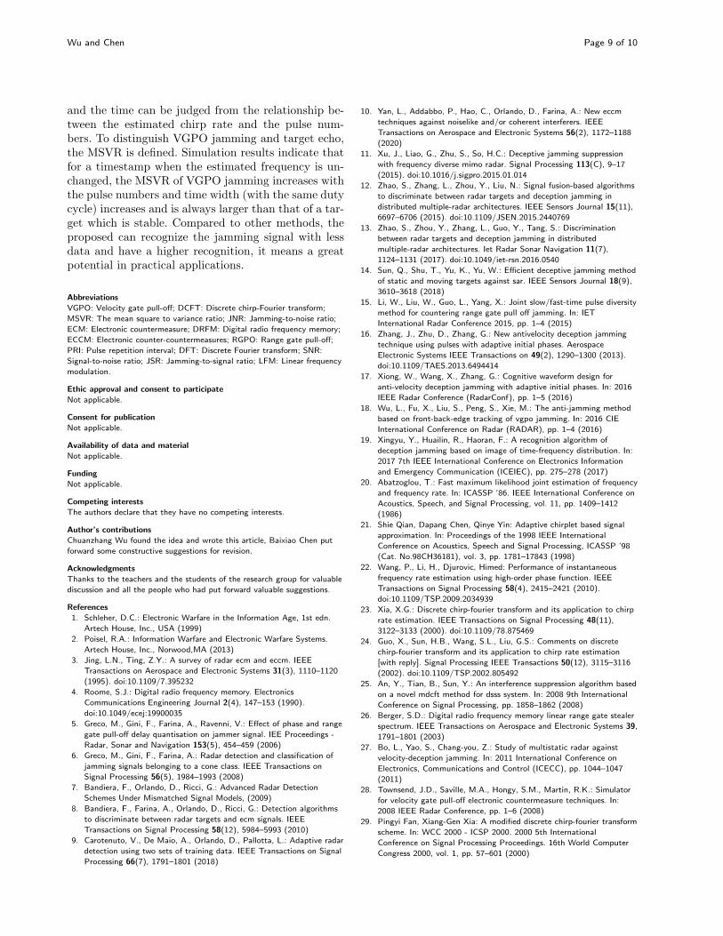
get with an acceleration 2.7 m/s2, a linear and nonlin-ear pull-off VGPO jamming are also considered. TheVf of the linear pull-off jamming is 2kHz/s. A nonlin-ear pull-off case is a simple form of the maneuveringscenario, and its Af is 20kHz/s2. The JSR is fixed as3dB, and the SNR changes from 0dB to 15dB. Therelationships between MSVR and SNR are shown inFig. 6.It can be seen that two kinds of VGPO jamming al-
most have the same MSVR. It means that the quadrat-ic term of the frequency pull-off function in (26) hasless effect on MSVR in a very short time (0.1s) if thecoefficient of the quadratic term is not too large (e.g.20kHz/s2).Different from the results of the linear and nonlin-
ear VGPO jamming, the MSVRs of the target is al-most steady which is similar to the result in Fig. 4(a).It means that the MSVR of the target signal is un-changed even with various parameters. Moreover, theMSVR of the target and the accelerated target are al-most the same. Combined with the MSVR of the twojamming signals, we can conclude that a tiny acceler-ation or small maneuvering on target hardly changesthe value of MSVR.
3.4 Discrimination PerformanceBefore we conduct the discrimination performance ofthe proposed method, we consider the influence ofthe speed of frequency offset, i.e., the value of Vf , onMSVR. The sampling frequency is 20MHz, and theSNR and JSR are 10dB and 5dB, respectively. Theother parameters are the same as the previous sub-section. The values of Vf are separately assumed as20kHz/s and 50kHz/s. The MSVR of target echo andjamming signal versus pulse numbers with various Vf
are shown in Fig. 7 where VGPO1 and VGPO2 sep-arately denote the linear VGPO jamming with Vf of20kHz/s and 50kHz/s.Apparently, the MSVR of the jamming signal with
Vf of 50kHz/s is larger than that of the jamming withVf of 20kHz/s. Furthermore, the more pulses involvedin the calculation, the greater the MSVR of the jam-ming signal, which is consistent with the result in Fig.4(b).To compare the performance with the results in [18]
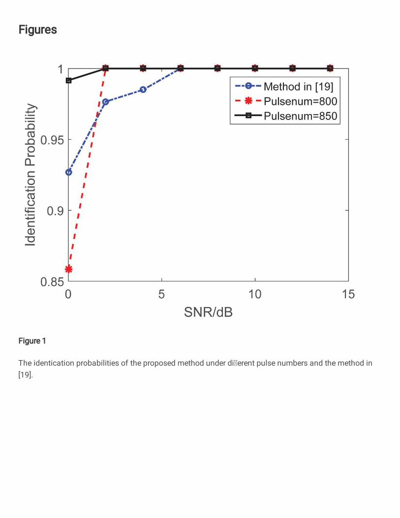
and [19], 800 and 850 pulses are separately considered,
with the same parameters in Fig. 6. The value of Vf isset as 20kHz/s, 300 Monte Carlo trials are considered.As the value of MSVR of the target signal is sable un-der different radar parameters, the threshold can beset as the average between the minimum MSVR ofthe jamming signal, which is usually the correspond-ing value when the SNR is 0dB, and the stable valueof MSVR of the target. In this simulation, the thresh-old is set as 0.65 as the MSVR of jamming signal isaround 0.8 when the SNR is 0dB in Fig. 6. Fig. 8 showsthe identification probability of jamming signal versusSNR based on the proposed method.From Fig.8, when the SNR is 0dB, the identification
probability of VGPO jamming could reach 0.975 with850 pulses, and 0.81 with 800 pulses. When the SNRis 2dB, the jamming signal can always be correctlyrecognized.From the aspect of the total data needed to correctly
identify the jamming signal, our method only uses thesignal data within 0.085s, and is less than the methodin [18] which needs the signal data within 0.096s. Fromthe aspect of the identification probability, our methodcan correctly recognize the jamming signal when theSNR is 2dB, which is smaller than that in [18] (theblue dotted line in Fig.8). It should be noted that thevalue of Vf is 50kHz/s in [18], which also means ourmethod would be better if the same value of Vf is usedbased on the result in Fig. 7.
3.5 DiscussionAlthough this method can recognize the VGPO jam-ming with less data and a higher recognition rate com-pared to the open literature, it is not suitable for thejamming of range gate pull-off (RGPO) with uniformacceleration. This is because its chirp rate after de-chirping is pretty small (about 0.2 for the false targetwith the same motion state with the same simulationparameters in this paper). However, as a more gener-al form of VGPO, the range-velocity gate pull-off (R-VGPO) jamming can also be identified by this method.Even in mixed-signal including target echo and jam-ming, this method is still effective.
4 ConclusionsIn this paper, the discrimination issue between the tar-get echo and the VGPO jamming is studied. To thispurpose, we resort the discrete chirp-Fourier transfor-m to jointly estimate the chirp rate and frequency ofa signal, and the scaling characteristic of the DCFTalgorithm is studied and explored to increase the es-timated accuracy in chirp rate domain. Based on theactual joint estimation results, the quantitative effectof the VGPO signal is further analyzed, it guaranteesthat the relationship between the pull-off acceleration
Wu and Chen Page 9 of 10
and the time can be judged from the relationship be-tween the estimated chirp rate and the pulse num-bers. To distinguish VGPO jamming and target echo,the MSVR is defined. Simulation results indicate thatfor a timestamp when the estimated frequency is un-changed, the MSVR of VGPO jamming increases withthe pulse numbers and time width (with the same dutycycle) increases and is always larger than that of a tar-get which is stable. Compared to other methods, theproposed can recognize the jamming signal with lessdata and have a higher recognition, it means a greatpotential in practical applications.
Abbreviations
VGPO: Velocity gate pull-off; DCFT: Discrete chirp-Fourier transform;
MSVR: The mean square to variance ratio; JNR: Jamming-to-noise ratio;
ECM: Electronic countermeasure; DRFM: Digital radio frequency memory;
ECCM: Electronic counter-countermeasures; RGPO: Range gate pull-off;
PRI: Pulse repetition interval; DFT: Discrete Fourier transform; SNR:
Signal-to-noise ratio; JSR: Jamming-to-signal ratio; LFM: Linear frequency
modulation.
Ethic approval and consent to participate
Not applicable.
Consent for publication
Not applicable.
Availability of data and material
Not applicable.
Funding
Not applicable.
Competing interests
The authors declare that they have no competing interests.
Author’s contributions
Chuanzhang Wu found the idea and wrote this article, Baixiao Chen put
forward some constructive suggestions for revision.
Acknowledgments
Thanks to the teachers and the students of the research group for valuable
discussion and all the people who had put forward valuable suggestions.
References
1. Schleher, D.C.: Electronic Warfare in the Information Age, 1st edn.
Artech House, Inc., USA (1999)
2. Poisel, R.A.: Information Warfare and Electronic Warfare Systems.
Artech House, Inc., Norwood,MA (2013)
3. Jing, L.N., Ting, Z.Y.: A survey of radar ecm and eccm. IEEE
Transactions on Aerospace and Electronic Systems 31(3), 1110–1120
(1995). doi:10.1109/7.395232
4. Roome, S.J.: Digital radio frequency memory. Electronics
Communications Engineering Journal 2(4), 147–153 (1990).
doi:10.1049/ecej:19900035
5. Greco, M., Gini, F., Farina, A., Ravenni, V.: Effect of phase and range
gate pull-off delay quantisation on jammer signal. IEE Proceedings -
Radar, Sonar and Navigation 153(5), 454–459 (2006)
6. Greco, M., Gini, F., Farina, A.: Radar detection and classification of
jamming signals belonging to a cone class. IEEE Transactions on
Signal Processing 56(5), 1984–1993 (2008)
7. Bandiera, F., Orlando, D., Ricci, G.: Advanced Radar Detection
Schemes Under Mismatched Signal Models, (2009)
8. Bandiera, F., Farina, A., Orlando, D., Ricci, G.: Detection algorithms
to discriminate between radar targets and ecm signals. IEEE
Transactions on Signal Processing 58(12), 5984–5993 (2010)
9. Carotenuto, V., De Maio, A., Orlando, D., Pallotta, L.: Adaptive radar
detection using two sets of training data. IEEE Transactions on Signal
Processing 66(7), 1791–1801 (2018)
10. Yan, L., Addabbo, P., Hao, C., Orlando, D., Farina, A.: New eccm
techniques against noiselike and/or coherent interferers. IEEE
Transactions on Aerospace and Electronic Systems 56(2), 1172–1188
(2020)
11. Xu, J., Liao, G., Zhu, S., So, H.C.: Deceptive jamming suppression
with frequency diverse mimo radar. Signal Processing 113(C), 9–17
(2015). doi:10.1016/j.sigpro.2015.01.014
12. Zhao, S., Zhang, L., Zhou, Y., Liu, N.: Signal fusion-based algorithms
to discriminate between radar targets and deception jamming in
distributed multiple-radar architectures. IEEE Sensors Journal 15(11),
6697–6706 (2015). doi:10.1109/JSEN.2015.2440769
13. Zhao, S., Zhou, Y., Zhang, L., Guo, Y., Tang, S.: Discrimination
between radar targets and deception jamming in distributed
multiple-radar architectures. Iet Radar Sonar Navigation 11(7),
1124–1131 (2017). doi:10.1049/iet-rsn.2016.0540
14. Sun, Q., Shu, T., Yu, K., Yu, W.: Efficient deceptive jamming method
of static and moving targets against sar. IEEE Sensors Journal 18(9),
3610–3618 (2018)
15. Li, W., Liu, W., Guo, L., Yang, X.: Joint slow/fast-time pulse diversity
method for countering range gate pull off jamming. In: IET
International Radar Conference 2015, pp. 1–4 (2015)
16. Zhang, J., Zhu, D., Zhang, G.: New antivelocity deception jamming
technique using pulses with adaptive initial phases. Aerospace
Electronic Systems IEEE Transactions on 49(2), 1290–1300 (2013).
doi:10.1109/TAES.2013.6494414
17. Xiong, W., Wang, X., Zhang, G.: Cognitive waveform design for
anti-velocity deception jamming with adaptive initial phases. In: 2016
IEEE Radar Conference (RadarConf), pp. 1–5 (2016)
18. Wu, L., Fu, X., Liu, S., Peng, S., Xie, M.: The anti-jamming method
based on front-back-edge tracking of vgpo jamming. In: 2016 CIE
International Conference on Radar (RADAR), pp. 1–4 (2016)
19. Xingyu, Y., Huailin, R., Haoran, F.: A recognition algorithm of
deception jamming based on image of time-frequency distribution. In:
2017 7th IEEE International Conference on Electronics Information
and Emergency Communication (ICEIEC), pp. 275–278 (2017)
20. Abatzoglou, T.: Fast maximum likelihood joint estimation of frequency
and frequency rate. In: ICASSP ’86. IEEE International Conference on
Acoustics, Speech, and Signal Processing, vol. 11, pp. 1409–1412
(1986)
21. Shie Qian, Dapang Chen, Qinye Yin: Adaptive chirplet based signal
approximation. In: Proceedings of the 1998 IEEE International
Conference on Acoustics, Speech and Signal Processing, ICASSP ’98
(Cat. No.98CH36181), vol. 3, pp. 1781–17843 (1998)
22. Wang, P., Li, H., Djurovic, Himed: Performance of instantaneous
frequency rate estimation using high-order phase function. IEEE
Transactions on Signal Processing 58(4), 2415–2421 (2010).
doi:10.1109/TSP.2009.2034939
23. Xia, X.G.: Discrete chirp-fourier transform and its application to chirp
rate estimation. IEEE Transactions on Signal Processing 48(11),
3122–3133 (2000). doi:10.1109/78.875469
24. Guo, X., Sun, H.B., Wang, S.L., Liu, G.S.: Comments on discrete
chirp-fourier transform and its application to chirp rate estimation
[with reply]. Signal Processing IEEE Transactions 50(12), 3115–3116
(2002). doi:10.1109/TSP.2002.805492
25. An, Y., Tian, B., Sun, Y.: An interference suppression algorithm based
on a novel mdcft method for dsss system. In: 2008 9th International
Conference on Signal Processing, pp. 1858–1862 (2008)
26. Berger, S.D.: Digital radio frequency memory linear range gate stealer
spectrum. IEEE Transactions on Aerospace and Electronic Systems 39,
1791–1801 (2003)
27. Bo, L., Yao, S., Chang-you, Z.: Study of multistatic radar against
velocity-deception jamming. In: 2011 International Conference on
Electronics, Communications and Control (ICECC), pp. 1044–1047
(2011)
28. Townsend, J.D., Saville, M.A., Hongy, S.M., Martin, R.K.: Simulator
for velocity gate pull-off electronic countermeasure techniques. In:
2008 IEEE Radar Conference, pp. 1–6 (2008)
29. Pingyi Fan, Xiang-Gen Xia: A modified discrete chirp-fourier transform
scheme. In: WCC 2000 - ICSP 2000. 2000 5th International
Conference on Signal Processing Proceedings. 16th World Computer
Congress 2000, vol. 1, pp. 57–601 (2000)

Wu and Chen Page 10 of 10
Figures
Figure 1 The flowchart of recognition process to VGPOjamming signal.
Figure 2 The DCFT results of the target echo and VGPOjamming signal with various scaling factor C. (a) Jamming(without scaling). (b) Target (without scaling). (c) Profiles of(a) and (b) after normalization. (d) Jamming (C=4e3). (e)Target (C=4e3). (f) Profiles of (a) and (b) afternormalization. (g) Jamming (C=2e7). (h) Target (C=2e7).(i) Profiles of (g) and (h) after normalization.
Figure 3 The estimated frequencies and chirp rates of targetecho and jamming signal versus time. (a) Linear scenario. (b)Non-linear scenario.
Figure 4 The MSVR of target echo and VGPO jammingunder different time width and pulse number.
Figure 5 Profiles of Fig. 4(b).
Figure 6 The MSVR of target echoes and VGPO jammingversus SNR.
Figure 7 The MSVR of the target echo and two kinds ofjamming signals versus pulse number.
Figure 8 The identification probabilities of the proposedmethod under different pulse numbers and the method in[19].
Figures
Figure 1
The identi cation probabilities of the proposed method under dierent pulse numbers and the method in[19].

Figure 2
The MSVR of the target echo and two kinds of jamming signals versus pulse number.
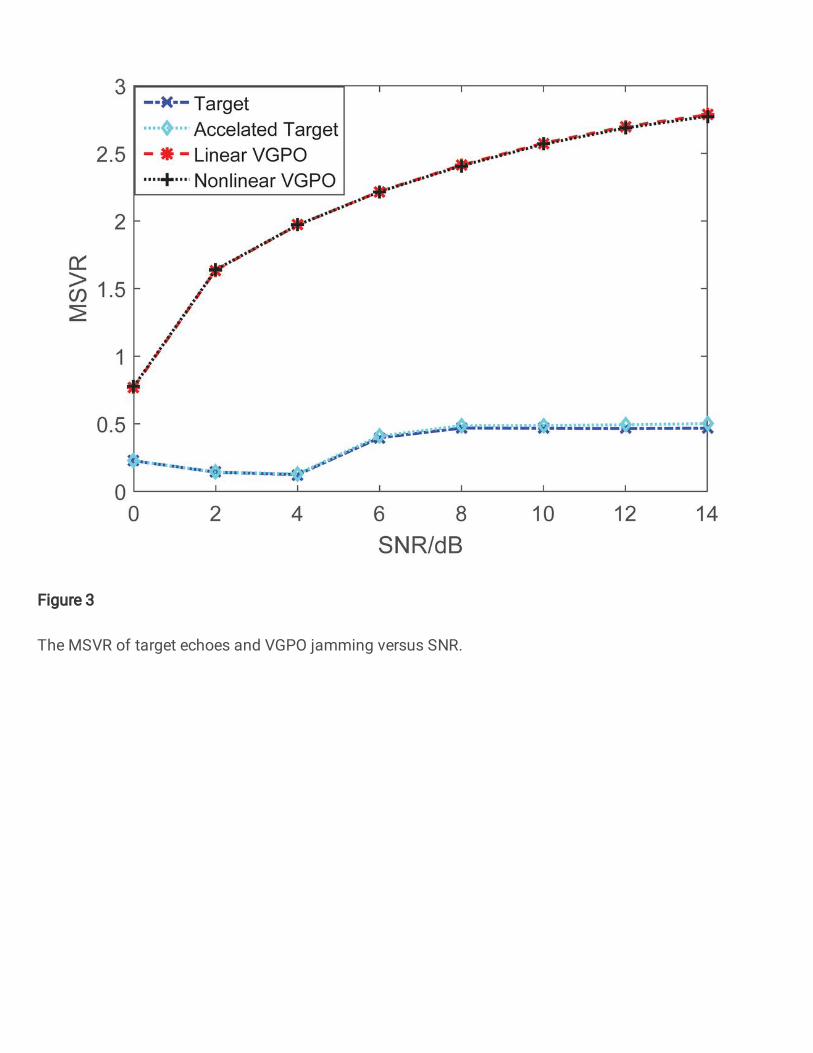
Figure 3
The MSVR of target echoes and VGPO jamming versus SNR.
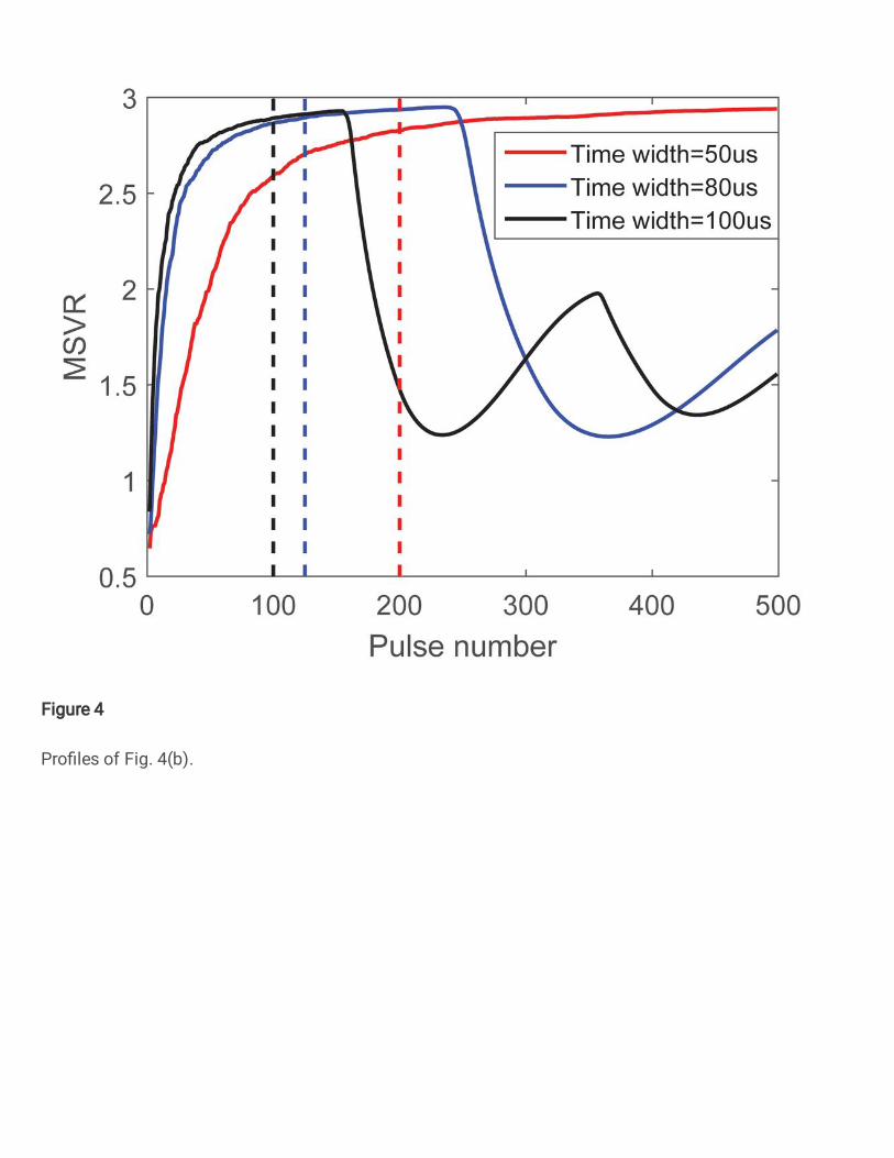
Figure 4
Pro� les of Fig. 4(b).

Figure 5
The MSVR of target echo and VGPO jamming under dierent time width and pulse number.
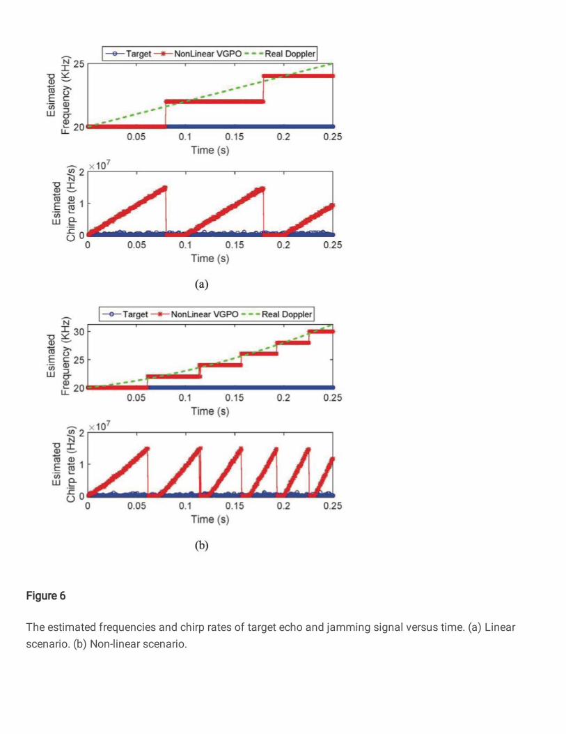
Figure 6
The estimated frequencies and chirp rates of target echo and jamming signal versus time. (a) Linearscenario. (b) Non-linear scenario.

Figure 7
The DCFT results of the target echo and VGPO jamming signal with various scaling factor. (a) Jamming(without scaling). (b) Target (without scaling). (c) Pro�les of (a) and (b) after normalization. (d) Jamming(C=1e3). (e) Target (C=1e3). (f) Pro�les of (a) and (b) after normalization. (g) Jamming (C=2e6). (h)Target (C=2e6). (i) Pro�les of (g) and (h) after normalization.

Figure 8
The �owchart of recognition process to VGPO jamming signal.
Supplementary Files
This is a list of supplementary �les associated with this preprint. Click to download.
Supp.zip


![A Discrete Subexponential Algorithm - umu.se · A Discrete Subexponential Algorithm ... Recently [6,1], we discovered that another subexponential randomization scheme for linear programming](https://static.fdocuments.us/doc/165x107/5e4fccefb756f36e8a3a171d/a-discrete-subexponential-algorithm-umuse-a-discrete-subexponential-algorithm.jpg)


![A Discrete Global Minimization Algorithm for …sjg/papers/tr-14-04.pdfthe global discrete minimal path using Dijkstra’s algorithm [5] (see Figure 1). Contribution In particular,](https://static.fdocuments.us/doc/165x107/5f9eec1065ed726ca96733a2/a-discrete-global-minimization-algorithm-for-sjgpaperstr-14-04pdf-the-global.jpg)

