A Real-Time Operating System for PICmicro …ww1.microchip.com/downloads/en/AppNotes/00585b.pdf ·...
40
1997 Microchip Technology Inc. DS00585B-page 5-105 INTRODUCTION Ever dream of having a Real-Time Kernel for the PIC16CXXX family of microcontrollers? Or ever won- der what Multitasking or Threads are all about? Then this article is for you. We will explore how to implement all of the features of a large Real-Time Multitasking Kernel in much less space, with more control, and with- out the large overhead of existing kernels. By planning ahead, and using the techniques outlined here, you can build your own fast, light, powerful, flexible real-time kernel with just the features needed to get the job done. Included in this article are two large examples: one on the PIC16C54, and the other on the more powerful PIC16C64. A “Remote Alarm” is implemented on the PIC16C54 as an example of a Non-Preemptive Kernel, with two asynchronous serial input sources capable of running up to 19,200 Baud along with seven sensors needing to be debounced as inputs. One more input line is monitored and causes an internal software recount. For output, this example has an LED that shows eight different internal states of the “Remote Alarm”, blinking at different rates and different sequences. Last but not least, is an asynchronous serial output capable of running at 38,400 Baud, pass- ing the inputs to the next remote alarm station. Several short and long timers are included to round out the nine cooperating tasks in this example. Please refer to Figure 2 and Appendix B. The second example is implemented on an PIC16C64 featuring an interrupt driven Semi-Preemptive Kernel. This example has the serial input and output routines of the first example moved into Interrupt Service Routines (ISR) for more speed and accuracy. The interrupt capa- bilities of the PIC16C64 will be explored, and a Real- Time Multitasking Kernel framework will be developed. Please refer to Figure 5 and Appendix C. Author: Jerry Farmer Myriad Development Company Why do I Need a Real-Time Kernel? Real-time design techniques allow the engineer/ designer to break-up large, complicated problems into smaller simpler tasks or threads. These more manageable units of code allow faster response to important events, while prioritizing the jobs to be done in a structured well-tested format. The kernel does the job of keeping the time, the peace between tasks, and keeping all the tasks’ communication flowing. More activities can be performed in the same amount of time by allowing other tasks to work while other tasks are waiting for some event to occur. Smaller code is also the result of using State-Driven techniques because much information is condensed into the state variables and code structure. If you need an example, look at the PIC16C54’s “Remote Alarm” code. What is Multitasking Anyway? This is the appearance of several tasks working at the same time. Each task thinks that it owns the CPU, but this appearance is controlled by the kernel. Only one task can be running at a time, but there is undone work that can be done by other tasks not blocked. Multitasking is the orchestration of interrupts, events, communication, shared data, and timing to get a job done. Real-Time Programming is just a bunch of ideas, concepts, and techniques that allow us to divide problems into units of code that are based on units of time, or events that drive a task from one state to another. AN585 A Real-Time Operating System for PICmicro™ Microcontrollers
Transcript of A Real-Time Operating System for PICmicro …ww1.microchip.com/downloads/en/AppNotes/00585b.pdf ·...
AN585A Real-Time Operating System for PICmicro™ Microcontrollers
INTRODUCTION
Ever dream of having a Real-Time Kernel for thePIC16CXXX family of microcontrollers? Or ever won-der what Multitasking or Threads are all about? Thenthis article is for you. We will explore how to implementall of the features of a large Real-Time MultitaskingKernel in much less space, with more control, and with-out the large overhead of existing kernels. By planningahead, and using the techniques outlined here, you canbuild your own fast, light, powerful, flexible real-timekernel with just the features needed to get the job done.
Included in this article are two large examples: one onthe PIC16C54, and the other on the more powerfulPIC16C64. A “Remote Alarm” is implemented on thePIC16C54 as an example of a Non-Preemptive Kernel,with two asynchronous serial input sources capable ofrunning up to 19,200 Baud along with seven sensorsneeding to be debounced as inputs. One more inputline is monitored and causes an internal softwarerecount. For output, this example has an LED thatshows eight different internal states of the “RemoteAlarm”, blinking at different rates and differentsequences. Last but not least, is an asynchronousserial output capable of running at 38,400 Baud, pass-ing the inputs to the next remote alarm station. Severalshort and long timers are included to round out the ninecooperating tasks in this example. Please refer toFigure 2 and Appendix B.
The second example is implemented on an PIC16C64featuring an interrupt driven Semi-Preemptive Kernel.This example has the serial input and output routines ofthe first example moved into Interrupt Service Routines(ISR) for more speed and accuracy. The interrupt capa-bilities of the PIC16C64 will be explored, and a Real-Time Multitasking Kernel framework will be developed.Please refer to Figure 5 and Appendix C.
Author: Jerry FarmerMyriad Development Company
1997 Microchip Technology Inc.
Why do I Need a Real-Time Kernel?
Real-time design techniques allow the engineer/designer to break-up large, complicated problems intosmaller simpler tasks or threads. These moremanageable units of code allow faster response toimportant events, while prioritizing the jobs to be donein a structured well-tested format. The kernel does thejob of keeping the time, the peace between tasks, andkeeping all the tasks’ communication flowing. Moreactivities can be performed in the same amount of timeby allowing other tasks to work while other tasks arewaiting for some event to occur. Smaller code is alsothe result of using State-Driven techniques becausemuch information is condensed into the state variablesand code structure. If you need an example, look at thePIC16C54’s “Remote Alarm” code.
What is Multitasking Anyway?
This is the appearance of several tasks working at thesame time. Each task thinks that it owns the CPU, butthis appearance is controlled by the kernel. Only onetask can be running at a time, but there is undone workthat can be done by other tasks not blocked.Multitasking is the orchestration of interrupts, events,communication, shared data, and timing to get a jobdone. Real-Time Programming is just a bunch of ideas,concepts, and techniques that allow us to divideproblems into units of code that are based on units oftime, or events that drive a task from one state toanother.
DS00585B-page 5-105
AN585
CONCEPTS
We will cover the basic concepts of kernels here so thatwe are using the same definitions when talking aboutthis difficult topic. This article is a very quick survey onReal-Time Kernel concepts. I hope to get you thinking,reading more, and hopefully writing RT OperatingSystems for your current and future projects. Manygreat books have been written about this very broadand interesting subject. We will refer to some of thesebooks which have a different point of view other thanthose expressed in this paper.
Critical Section
A critical section is a shared data structure, or a sharedresource, or a critical time section of code, or a non-re-entrant section of code that can have only one ownerthat is allowed to view/change/use that section at anyone time. These sections must not be interruptedduring the update process. They must be protected sothat other tasks can not get in and change the pointers/data or modify the hardware at the same time. Remem-ber that if two tasks can get into a critical section, at thesame time, then data WILL be corrupted. Make surethat critical sections are small, with time for pendinginterrupts to get serviced. Not understanding criticalsections is where the beginning RT programmers getinto the most trouble. Even without interrupts, you mustprotect variables that are changing over time, such asthe byte sized variable xmt_byte used in thePIC16C54 example. This variable changes each timethe STATE changes for the Serial Out Task.Semaphores, and Disabling Interrupts are two of thetechniques used to coordinate between different taskswanting to control a critical section. Task #4 is devotedto the proper feeding of the shared Serial Out Resourcein the PIC16C54 example. Note the use of the binarysemaphore “OState_B” to control Task #4, Task #1,and the variable xmt_byte. There are several moreexamples of critical sections in the PIC16C64 exampledue to the use of interrupts. We disable interrupts forvery short time periods to protect these areas. Also inthe PIC16C64 example, all critical sections are finishedbefore checking to see if the kernel wants another taskto start running instead of the current task. We will dis-cuss in more detail how to protect critical sections laterin this article.
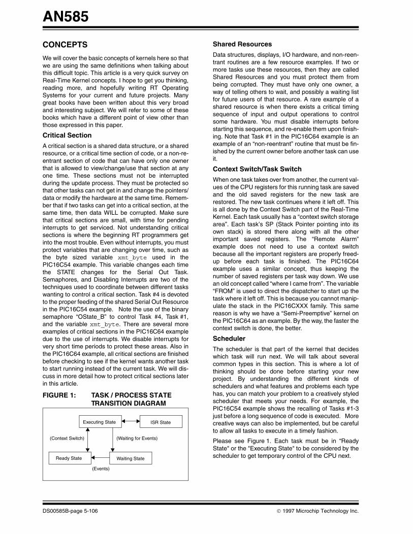
FIGURE 1: TASK / PROCESS STATE TRANSITION DIAGRAM
(Context Switch) (Waiting for Events)
Executing State ISR State
Ready State Waiting State
(Events)
DS00585B-page 5-106
Shared Resources
Data structures, displays, I/O hardware, and non-reen-trant routines are a few resource examples. If two ormore tasks use these resources, then they are calledShared Resources and you must protect them frombeing corrupted. They must have only one owner, away of telling others to wait, and possibly a waiting listfor future users of that resource. A rare example of ashared resource is when there exists a critical timingsequence of input and output operations to controlsome hardware. You must disable interrupts beforestarting this sequence, and re-enable them upon finish-ing. Note that Task #1 in the PIC16C64 example is anexample of an “non-reentrant” routine that must be fin-ished by the current owner before another task can useit.
Context Switch/Task Switch
When one task takes over from another, the current val-ues of the CPU registers for this running task are savedand the old saved registers for the new task arerestored. The new task continues where it left off. Thisis all done by the Context Switch part of the Real-TimeKernel. Each task usually has a “context switch storagearea”. Each task’s SP (Stack Pointer pointing into itsown stack) is stored there along with all the otherimportant saved registers. The “Remote Alarm”example does not need to use a context switchbecause all the important registers are properly freed-up before each task is finished. The PIC16C64example uses a similar concept, thus keeping thenumber of saved registers per task way down. We usean old concept called “where I came from”. The variable“FROM” is used to direct the dispatcher to start up thetask where it left off. This is because you cannot manip-ulate the stack in the PIC16CXXX family. This samereason is why we have a “Semi-Preemptive” kernel onthe PIC16C64 as an example. By the way, the faster thecontext switch is done, the better.
Scheduler
The scheduler is that part of the kernel that decideswhich task will run next. We will talk about severalcommon types in this section. This is where a lot ofthinking should be done before starting your newproject. By understanding the different kinds ofschedulers and what features and problems each typehas, you can match your problem to a creatively styledscheduler that meets your needs. For example, thePIC16C54 example shows the recalling of Tasks #1-3just before a long sequence of code is executed. Morecreative ways can also be implemented, but be carefulto allow all tasks to execute in a timely fashion.
Please see Figure 1. Each task must be in “ReadyState" or the "Executing State" to be considered by thescheduler to get temporary control of the CPU next.
1997 Microchip Technology Inc.

AN585
Non-Preemptive Kernel
The Non-Preemptive Kernel is also called a“Cooperative Kernel” because the tasks only give-upcontrol when they want/need to in coordination withother tasks, and events. The “Remote Alarm” exampleuses a Non-Preemptive Kernel type, showing thatdespite its reputation as being a simple kernel type, alot can be done with it. The Non-Preemptive Kerneltype is well suited for the non-interrupt typePIC16C5Xs. The heart beat of the PIC16C54 exampleis the internal TMR0 counter crossing over from a highvalue to a low value of the counter. Use the prescaler toadjust the time units. The very fast tasks continuallyread the TMR0 directly comparing the delta of time tosee if it should fire.
Preemptive Kernel
In a Preemptive Kernel, a running task can be swappedout for a higher priority task when it becomes ready.The Preemptive Kernel relies much more on interruptsas its driving force. The context switch is at the heart ofthis type of kernel. To implement a true Preemptive Ker-nel, you must be able to manipulate the stack. This iswhy we implemented a “Semi-Preemptive” kernel onthe PIC16C64, with some of the best features of bothtypes of kernels. We moved some of the tasks in thePIC16C54 example into ISRs to handle the I/Os. Thisworks very well as the ISRs are very short and do mostof the real work in this example. The TIMER0 interruptis the heart beat for the PIC16C64 example. You musthave a clock interrupt in order to make a truePreemptive kernel.
Round Robin Scheduler
When the scheduler finds tasks on the ready queuethat have the same priorities, the scheduler often usesa technique called Round Robin scheduling to makesure each task gets its day in the sun. This means morehousekeeping to get it right. This is part of the creativeways you can tailor the scheduler to fit your needs. Inthe PIC16C54 example, all tasks will get to run shortlyafter their appointed time. This means that no task willdominate all others in this simple approach. In the“olden” days of the first Real-Time Operating Systemsthe term was used to mean the same as “time slicing”.The Preemptive Kernels of today are a major stepforward, with their priority schemes, and intertaskcommunication capabilities.
1997 Microchip Technology Inc.
Preemptive vs. Non-Preemptive
The Preemptive Kernel is harder to develop, but is eas-ier to use, and is sometimes used incorrectly. You mustspend more upfront time with the Non-Preemptive Ker-nel but it is better for more cramped microcontrollers.You get much better response time between a cause/event and the response/action for that event with aNon-Preemptive Kernel. The Preemptive Kernel ismore predictable in the response times, and can be cal-culated as to the maximum time to complete a givenjob. Often the Preemptive Kernel is more expensive.
Reentrancy
In a Preemptive Kernel, two or more tasks may want touse the same subroutine. The problem is that you cannot control when a task is swapped out and whenanother takes its place. Thus, if a subroutine uses onlylocal or passed variables that are stored only in eachtasks’ stack, then it is call reentrant or a pure routine.No global variables or hardware may be used in such apure routine. A way around this reentrancy requirementis to treat the whole subroutine as a critical section.
Appendix D is an example of reentrant code segmentas might have been used in the PIC16C54 codeexample.
Task Priority
Some tasks are not created equal. Some jobs must bedone on time or data will be lost. Make the tasks thatmust get done the highest priority and go down thescale from there. Some kernels make you have adifferent priority for each task. This is a good idea andrequires some thought before coding to make thedesign work.
Static vs. Dynamic Priorities and Priority Inversions
For most embedded Real-Time Kernels, both staticpriorities and static tasks are used. Dynamic prioritiesare sometimes used to solve deadlock and othercomplex situations that arise from not understandingthe problem and not understanding Real-TimeTechniques. If the need for dynamic priorities seem tooccur, you should relook at how you divided the prob-lem, and divide less so as to include the resources inquestion under one semaphore. You could divide theproblem more to have more tasks not needing two ormore resources to complete its job, and have the newtasks talk more together.
DS00585B-page 5-107

AN585
As for Dynamic tasks, you should define the problem soas to know, ahead of coding, the continuous use of alltasks. You will need more upfront time in the planningstage to get all tasks talking, but it is well worth it tokeep Dynamic Priorities and Dynamic Tasking out ofthe kernel design.
Priority Inversions is a trick used to get past a poorlydesigned system by inverting the priorities to allowlower tasks to run that were previously blocked. This isa cheap trick, and is best kept out of a Real-Time Ker-nel. Use the other techniques outlined in this section tosolve this kind of problem.
Semaphores
There are basically two types: binary and countingsemaphores. The binary semaphore allows only oneowner, and all other tasks wanting access are made towait. The counting semaphore keeps a list of users thatneed access. Semaphores can be used in many ways.We will illustrate most of them in the following para-graphs. Note that you can implement counting sema-phores using binary semaphores.
Mutual Exclusion
We have touched on the subject of Mutual Exclusionearlier (a method to exclude other tasks from gainingaccess to critical sections). Mutual Exclusion is theprocess of excluding others from access to the sharedresources. To make a semaphore is a very complicatedprocess. The semaphore’s construction must beatomic. That means that once the process has started,it can not be interrupted until it has saved the name ofthe new owner. From there on, it knows that no one elsecan break-in and change owners. We haveimplemented a binary semaphore using bits and kernelfunctions to mutually exclude access in the PIC16C54example.
In the PIC16C64 example, we also disable interrupts toget the same effect. There are at least two good waysof implementing a binary semaphore. The first andoldest way was discovered by a Dutch mathematiciannamed Dekker. We will refer you to a book that talksmore about this algorithm. The second method ofimplementing a binary semaphore was also discoveredby another Dutchman named Dijkstra. This methoduses the “testandset” type instruction and is much moreimportant to us. We used the dec & jump if notzero instruction (see PIC16C64 example).
Deadlock
Deadlock is a condition where two or more tasks ownresources that other tasks need to complete thereassignment but will not release their own resourcesuntil the other tasks release theirs. Talk aboutcooperation. Please read section, "Static vs. DynamicPriorities and Priority Inversions" for a discussion aboutsuch problems and ways to solve them. The root ofsuch problems is not understanding the originalproblem.
DS00585B-page 5-108
Synchronization
Semaphores can be used to synchronize tasks so thatmessages can be passed between them. Also taskscan be started up by semaphores, stopped bysemaphores, or started together. They are thefoundation blocks for Real-Time Programming. Onceyou have built a binary semaphore for your kernel, youcan build very complex semaphores to synchronizeanything. In the PIC16C54 example, data from severalsources are passed out the Serial Port Resource.Task #4 synchronizes the other tasks trying to senddata out and synchronizes with task #1 to get it done.When task #1 is running, then task #4 can not run untiltask #1 is ready for more data to send out.
Intertask Communication
We have touched on this topic already, but for large ker-nels, one can include more complex communicationmethods to pass data/messages between tasks. Muchof the handshaking is done for you inside the kernel.This takes a lot more space and execution speed toimplement them in a kernel.
Event Flags
We implemented Event Flags as simple bits having twostates (on and off). More info can be stored per EventFlag such as time it was recorded, by who, and who theevent belongs to, and whether data was lost.
Message Mailboxes
This is a nice feature to have if you have the ram space.Mailboxes allow the designer to pass messagesbetween tasks, and allows messages to be looked atwhen the task is ready, and to reply telling the senderthat the message was received. One message can besent to many tasks at the same time.
Message Queues
This again is a very nice feature if you have the execu-tion time, and the ram to implement them. This featureis related to Mailboxes, in that you can store severalmessages even after reading, to be processed later. Ifyou want to only operate on the highest prioritizedmessages before handling the rest, this is allowed. Youcan be very fancy with the Mailboxes and Queues. Ifyou have them, use them.
1997 Microchip Technology Inc.

AN585
Interrupts
Interrupts are one of the best inventions to come alongfor solving Real-Time problems. You can get very quickresponse to the need, and then go back to what youwere doing. The only problem is that they can and dohappen at the worst times. That means that you mustlearn how to turn them on and off to protect your criticalsections. Note that before an interrupt can be handled,you must save all important registers so that you canrestore them so that the kernel can restart the taskwhere it left off. This is much like the context switchissue, but for interrupts, you must always save andrestore. In the PIC16C64 example, the Status, W, andFSR registers are saved in RAM because of theinterrupt. The PC register is saved onto the stack byhardware.
Interrupt Latency, Response and Recovery
Interrupt Latency is defined as the largest time periodthat interrupts are disabled, plus the time it takes for theISR to start to execute.
The Interrupt Response Time is defined for a Non-Preemptive system as Interrupt Latency plus the“context saving time.” For a Preemptive system, addthe execution time for the kernel to record the interrupt.
Interrupt Recovery Time for a Non-Preemptive systemis defined as the time to restore the saved context andfor the restarting of the task that was interrupted.Interrupt Recovery Time for a Preemptive system is thesame as for the Non-Preemptive system plus the timethe kernel takes in the scheduler deciding which task torun next. These measurements are how most kernelsare compared with each other. The PIC16C64 exampledoes very well in these measurements. That isbecause of the PIC16CXXX processor and that theyare mostly a Non-Preemptive system. You must keepthe time you disable interrupts to a minimum in any ker-nel you write or any task that you write. You shouldbreak-up long sequences of instructions to allow forinterrupts that are already waiting to execute.
1997 Microchip Technology Inc.
ISR Processing Time
ISR (Interrupt Service Routine) Processing Time isdefined as the time an ISR keeps control of the CPU.This amount of time should be short, and if a lot ofprocessing needs to be done in a ISR, then break upthe ISR. The new ISR should now just store the newdata and return. Next, create a new task and move theextra code from the old ISR into the new task.Remember that the longer you are in one interrupt, thelonger you can not answer another pressing interrupt.
Nesting interrupts are where the interrupt with a higherpriority can interrupt a lower priority interrupt. Caremust be used, as different interrupts may have criticalsections too, and disabling interrupts must be usedhere too to protect critical sections. Nesting ofinterrupts may not exist on all microcontrollers, such asthe PIC16CXXX family.
Non-Maskable Interrupts
On some microprocessors, you can enable/disableselected interrupts, such as on the PICmicro family.This is a great tool to control the flow of data into thesystem and out. Some systems have what is calledNon-Maskable Interrupts. Here you can not turn themoff by software masking. These NMIs as they are callfor short, are used as clock Ticks, because you do notwant problems with complex critical sections on ainterrupt that you can not turn off. The PIC16CXXXfamily does not have any NMIs. NMIs are not as usefulas maskable interrupts.
Clock Tick
The Clock Tick, is the heart beat of the system. This ishow the kernel keeps time (relative & absolute). This ishow the kernel is restarted to see if there is a delay thathas finished, so that the task can be moved into theready state. In the PIC16C54 example, the Timer0clock is used. In the PIC16C64 example, Timer0 isused. You must have a clock interrupt in order to makea true Preemptive kernel. This is the other reason whywe implemented a Non-Preemptive Kernel on thePIC16C54 - no clock interrupt.
DS00585B-page 5-109

AN585
ANALYSIS OF CODE EXAMPLES
These sections are the real meat of this article. In thesesections we will explain how the concepts are put topractical use line by line in each of the two mainexamples - PIC16C54 (Appendix C) and PIC16C64(Appendix D).
We will also examine a short reentrant code example inAppendix B. We will give some ideas on how to expandthe examples and how far and how fast the examplescan be pushed. Be sure to read both sections on thetwo examples.
The “Remote Alarm” application has many interestingfeatures. The concept is to have as many tiers of unitslike a tree feeding into the lower level units the status ofeach of the larger branches to one central point. Eachunit can detect any changes in status before theintruder shuts that unit down, or tampers with it. If anyunit’s power or wires connecting it down the tree arecut, the lack of the flow of status and passwords wouldbe noticed in five seconds and reported down the line.The two Serial Input lines per unit receive the statusand passwords from it’s two larger branches, checkingthe data and passing the info down the line by its ownSerial Output line. The seven input status lines aredebounced in these examples, showing the technique.
The LED on each unit reports the status at that node asto the importance of its own seven input status linesand the status flowing down the line. The levelindication outputted on the LED continues at the lasthighest level until either a reset is received on the“Reset State” line or five minutes of no new activity onthe seven input status lines are received. When eitherof these two events occur, the level of the LED output isadjusted to the current level of input. Some of the fea-tures are changed for this article (Figure 2 andFigure 5).
Another Embedded System use of this type of “RemoteAlarm” application is that of placing the unit on theoutside of a safe. Hopefully the intruder would bedetected before arriving at the unit itself. Thecontinuous stream of status and passwords to thelarger unit inside would slow down any simple theft.
PIC16C54 - “Remote Alarm” Example
This example is a cross between a true application andan attempt to show new concepts and some extrafeatures for show. Some of the application specificcode has been removed to show more clearly thepossibilities of a Real-time Operating System on thePICmicro family. We chose the Baud rate for the Serialoutput to be twice the speed of the two Serial inputsbecause it is harder to accurately output a preciseSerial Output than it is to monitor Serial inputs.
DS00585B-page 5-110
FIGURE 2: REMOTE ALARM-PIC16C54 EXAMPLE
This example operates at 4 Mhz. By simply increasingthe crystal speed to 8 MHz, the two Asynchronousinput Serial Baud rates increase from 4800 Baud to9600 Baud. The Serial Output Baud rate increasesfrom 9600 Baud to 19,200 Baud. By increasing thecrystal speed to 16 MHz, it will increase the Baud ratesto 19,200 Baud for the two independent Asynchronousinputs, and increase the baud rate for theAsynchronous Serial output to 38,400 Baud. Byadjusting the constants in the code for the Serialroutines, other Baud rates can be achieved at othercrystal speeds. Note that you must use a very stablecrystal setup and NOT an RC combination to run theseexamples.
We will now give a quick outline of the PIC16C54 codeexample. Lines 1-85 are the equates for this program.Lines 88-95 are simple jump tables so as to save someof the precious “first 256 bytes” of each page. TheSerial Output Routines - Task #1 are in lines 97-159.Task #7’s subroutines start at line 160 and continue toline 277. In this section, the LED output is controlled.The subroutine QCheck_T123, lines 278-301, is usedto allow the checking of Tasks #1-3 to see if they areready to execute before a long section of code in aslower Task is about to be executed. This is a creativeway for the Kernel’s Scheduler to makes sure that thehighest Prioritized Tasks get serviced before the lessimportant tasks get executed. Task #2 starts at line302. This task reads the Serial Input #1 forAsynchronous data. Task #2 can be described as aState Machine for outputting a byte Serially. Task #3interrupts the code of Task #2 at line 333 and continuesuntil line 362. Task #3 also reads the Serial Input but oninput #2. Task #2’s subroutines continue at line 363 andcontinue until line 423. Task #3’s subroutines continueat line 424 and continue until line 484 is reached. Themain or starting code is started at line 485. From thatline to line 515, all variables are initialized, and all tasksare initialized at this time also. The Main Loop is startedat line 516 and ends at line 665. This is where the realaction is done. Each task checks the time to see if theconditions are correct for it to run. The tasks that arenot Blocked, and have a job to do now are in a ReadyState. In the Main Loop, we check the current state of
Serial IN 1
Serial IN 2
7 Sensors IN
Reset State
LED Level
Serial OUT
PIC16C54
RemoteAlarm
1997 Microchip Technology Inc.
AN585
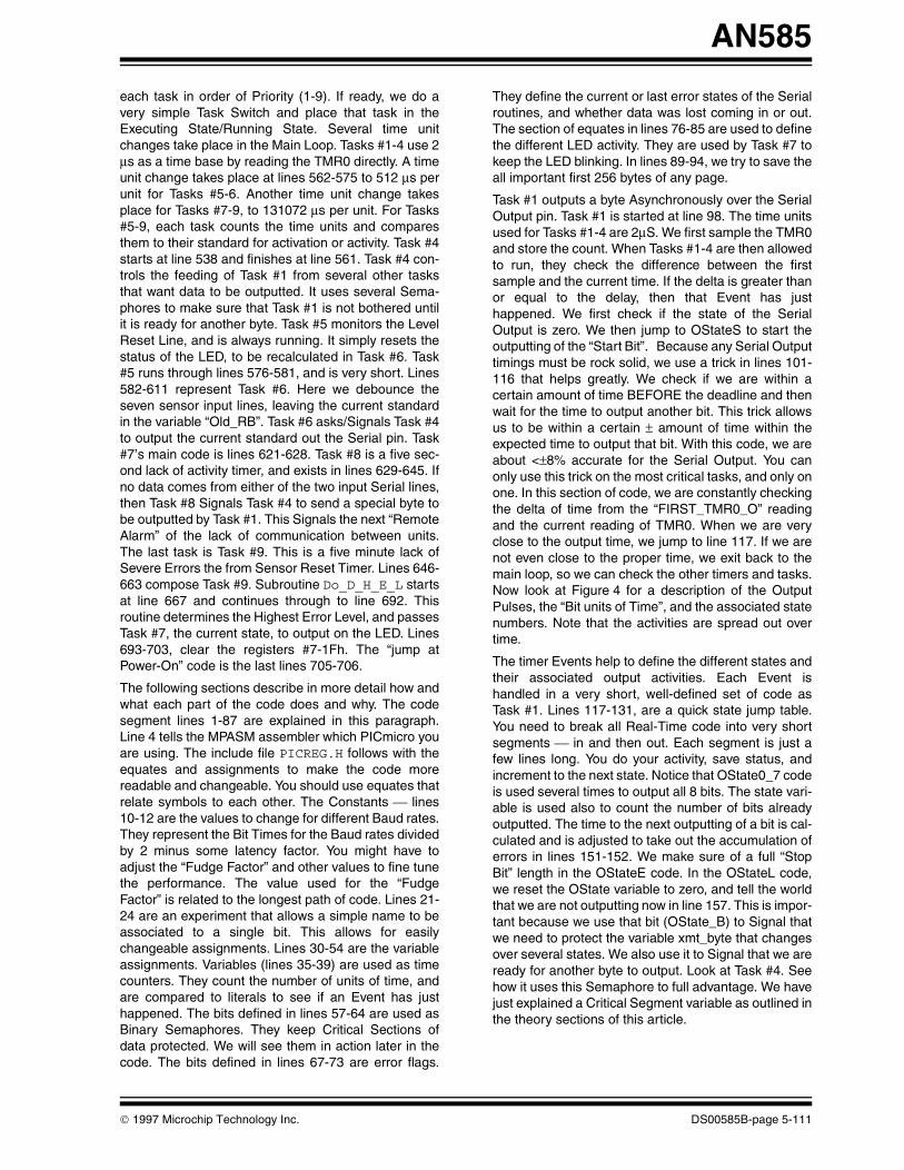
each task in order of Priority (1-9). If ready, we do avery simple Task Switch and place that task in theExecuting State/Running State. Several time unitchanges take place in the Main Loop. Tasks #1-4 use 2µs as a time base by reading the TMR0 directly. A timeunit change takes place at lines 562-575 to 512 µs perunit for Tasks #5-6. Another time unit change takesplace for Tasks #7-9, to 131072 µs per unit. For Tasks#5-9, each task counts the time units and comparesthem to their standard for activation or activity. Task #4starts at line 538 and finishes at line 561. Task #4 con-trols the feeding of Task #1 from several other tasksthat want data to be outputted. It uses several Sema-phores to make sure that Task #1 is not bothered untilit is ready for another byte. Task #5 monitors the LevelReset Line, and is always running. It simply resets thestatus of the LED, to be recalculated in Task #6. Task#5 runs through lines 576-581, and is very short. Lines582-611 represent Task #6. Here we debounce theseven sensor input lines, leaving the current standardin the variable “Old_RB”. Task #6 asks/Signals Task #4to output the current standard out the Serial pin. Task#7’s main code is lines 621-628. Task #8 is a five sec-ond lack of activity timer, and exists in lines 629-645. Ifno data comes from either of the two input Serial lines,then Task #8 Signals Task #4 to send a special byte tobe outputted by Task #1. This Signals the next “RemoteAlarm” of the lack of communication between units.The last task is Task #9. This is a five minute lack ofSevere Errors the from Sensor Reset Timer. Lines 646-663 compose Task #9. Subroutine Do_D_H_E_L startsat line 667 and continues through to line 692. Thisroutine determines the Highest Error Level, and passesTask #7, the current state, to output on the LED. Lines693-703, clear the registers #7-1Fh. The “jump atPower-On” code is the last lines 705-706.
The following sections describe in more detail how andwhat each part of the code does and why. The codesegment lines 1-87 are explained in this paragraph.Line 4 tells the MPASM assembler which PICmicro youare using. The include file PICREG.H follows with theequates and assignments to make the code morereadable and changeable. You should use equates thatrelate symbols to each other. The Constants lines10-12 are the values to change for different Baud rates.They represent the Bit Times for the Baud rates dividedby 2 minus some latency factor. You might have toadjust the “Fudge Factor” and other values to fine tunethe performance. The value used for the “FudgeFactor” is related to the longest path of code. Lines 21-24 are an experiment that allows a simple name to beassociated to a single bit. This allows for easilychangeable assignments. Lines 30-54 are the variableassignments. Variables (lines 35-39) are used as timecounters. They count the number of units of time, andare compared to literals to see if an Event has justhappened. The bits defined in lines 57-64 are used asBinary Semaphores. They keep Critical Sections ofdata protected. We will see them in action later in thecode. The bits defined in lines 67-73 are error flags.
1997 Microchip Technology Inc.
They define the current or last error states of the Serialroutines, and whether data was lost coming in or out.The section of equates in lines 76-85 are used to definethe different LED activity. They are used by Task #7 tokeep the LED blinking. In lines 89-94, we try to save theall important first 256 bytes of any page.
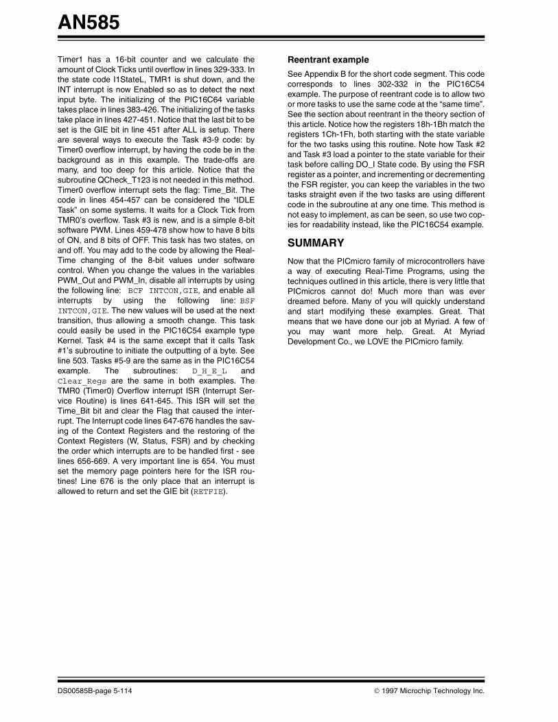
Task #1 outputs a byte Asynchronously over the SerialOutput pin. Task #1 is started at line 98. The time unitsused for Tasks #1-4 are 2µS. We first sample the TMR0and store the count. When Tasks #1-4 are then allowedto run, they check the difference between the firstsample and the current time. If the delta is greater thanor equal to the delay, then that Event has justhappened. We first check if the state of the SerialOutput is zero. We then jump to OStateS to start theoutputting of the “Start Bit”. Because any Serial Outputtimings must be rock solid, we use a trick in lines 101-116 that helps greatly. We check if we are within acertain amount of time BEFORE the deadline and thenwait for the time to output another bit. This trick allowsus to be within a certain ± amount of time within theexpected time to output that bit. With this code, we areabout <±8% accurate for the Serial Output. You canonly use this trick on the most critical tasks, and only onone. In this section of code, we are constantly checkingthe delta of time from the “FIRST_TMR0_O” readingand the current reading of TMR0. When we are veryclose to the output time, we jump to line 117. If we arenot even close to the proper time, we exit back to themain loop, so we can check the other timers and tasks.Now look at Figure 4 for a description of the OutputPulses, the “Bit units of Time”, and the associated statenumbers. Note that the activities are spread out overtime.
The timer Events help to define the different states andtheir associated output activities. Each Event ishandled in a very short, well-defined set of code asTask #1. Lines 117-131, are a quick state jump table.You need to break all Real-Time code into very shortsegments in and then out. Each segment is just afew lines long. You do your activity, save status, andincrement to the next state. Notice that OState0_7 codeis used several times to output all 8 bits. The state vari-able is used also to count the number of bits alreadyoutputted. The time to the next outputting of a bit is cal-culated and is adjusted to take out the accumulation oferrors in lines 151-152. We make sure of a full “StopBit” length in the OStateE code. In the OStateL code,we reset the OState variable to zero, and tell the worldthat we are not outputting now in line 157. This is impor-tant because we use that bit (OState_B) to Signal thatwe need to protect the variable xmt_byte that changesover several states. We also use it to Signal that we areready for another byte to output. Look at Task #4. Seehow it uses this Semaphore to full advantage. We havejust explained a Critical Segment variable as outlined inthe theory sections of this article.
DS00585B-page 5-111

AN585
Task #2 reads the Serial Input line 1, running at 4800Baud. The code structure is very similar to that ofTask #1 (Figure 3). Notice that there are more statesthan the Serial Output Task #1. Once the “Start Bit” isdetected, we half step into the “Start Bit” to see if it wasa “False Start” or not. We then sample and store theincoming bits to form an 8-bit byte just like Task #1. Wesample the “Stop Bit” to see if it is a “Frame Error”. Wedelay another 1/2 bit to get to the end of the “Stop Bit”if there was an “Frame Error” before resetting Task #1’sstate to 0. Otherwise, we reset Task #1’s state to 0, andSignal that we are ready for another “Start Bit”. The justreceived byte is stored in variable “RCV_Storage”. Acheck is made to see if we already sent out the lastreceived byte before clobbering the old byte with thenew byte.
Task #3 reads the Serial Input line 2, running at 4800Baud. The code structure is the same as Task #2Figure 3). The received byte is also put into the samestorage variable as Task #2 - “RCV_Storage”. Wheneither Task #2 or Task #3 receives a valid byte, Task#8’s counter is reset. You can up the Baud rate of Task#2 and 3 if you lower the output Baud rate of Task #1.Note that for reading the Serial Input Lines, you can beoff by ±15% for each sampling, but not accumulatively.
DS00585B-page 5-112
Task #4 finds the next buffered byte to send out throughTask #1. Task #4 also controls the order of which bytegoes first over another less important byte of data. Itcan be said that Task #1 Blocks Task #4 from running.You can think of the Serial Output Line as a SharedResource. The use of Semaphores here allow theSynchronization of data and actions.
Task #5 monitors the Level Reset Input Line and willreset the LED state variable if the line ever goes low.This task is always in the Ready State. This task is saidto simply “pole the input line” when ever it can.
Task #6 debounces the seven sensor input lines,running every 20 ms. The variable “T_20_mS_CO” isincremented every 512 µs (Clock Tick) and is com-pared to the count needed to equal 20 ms. If it is time,the subroutine QCheck_T123 is called to see if Tasks#1-3 are in the Ready State. If any of the Tasks #1-3 areready, they are ran and we then continue with Task #6.We compare the current value of the input Port_B tosee if it stayed the same from the last reading 20 msback. If the two readings are the same, then Port_B isconsidered to be stable and the possibly new value isplaced in the variable “Old_RB” to be outputted by Task#1. The subroutine D_H_E_L is called to determine thenew LED state. We then check if Task #1 was too busyto output the last sensor status byte, if so then that erroris recorded.
FIGURE 3: SERIAL INPUT STATES vs. TIME DIAGRAM
FIGURE 4: SERIAL OUTPUT STATES vs. TIME DIAGRAM
Start 0 1 2 3 4 5 6 7 StopBit Bit
State 0 1 2 3 4 5 6 7 8 9 A B
1/2 1 1 1 1 1 1 1 1 1 1/2 (Bit unit of time)
First Detected
Start 0 1 2 3 4 5 6 7 StopBit Bit
State 0 1 2 3 4 5 6 7 8 9 A
1 1 1 1 1 1 1 1 1 1 (Bit unit of time)
1997 Microchip Technology Inc.
AN585
Task #7 outputs the Highest Severity Level Indicationon the LED. Do_LED starts at line 161, and continuesto 276. This task is also broken into small time units ofcode. It is constantly checking to see if it is time toswitch the on/off condition of the LED. The time units forTask #7 are regulated by the code in lines 613-619.131072 µS = time unit for Tasks #7-9. Task #7 hasmany state jump tables so it is included in the first 256bytes of the first page. Lines 168-175 explain the onand off sequences and offs that represent levels ofseverity of the input status lines. The variable“LED_Mode” has both Task #7’s current state numberand the sub-state-number for that state’s outputsequence.
Task #8 is a 5 second lack of input from either of the twoSerial input timers. Tasks #2 and #3 will reset the timecounter for Task #8, when either receives a full byte. Ifthe time counter “T_5_S_CO” equals 5 secs, then theLED’s state is bumped to the highest, and a specialbyte is sent down the line to the next “Remote Alarm”unit. The counter variable is reset, and count starts allover. We then check if Task #1 was too busy to outputthe last special status byte, if so then that error isrecorded.
Task #9 measures 5 minutes of calm on the 7 sensorlines and then resets the LED’s state. Task #9 needs 16bits of counter power to record 5 minutes of time. Thecounter variables are reset after being triggered.
Do_D_H_E_L determines the LED’s next state basedon the 7 sensor input status. This subroutine checkseach bit to see if it is active and then checks if a changein the LED’s current state needs changing.
Do_Clear_Regs clears registers 7-1Fh. It leaves theFSR register zeroed out. This is very important for thePIC16C57 chip.
PIC16C64 - “Remote Alarm64” Example
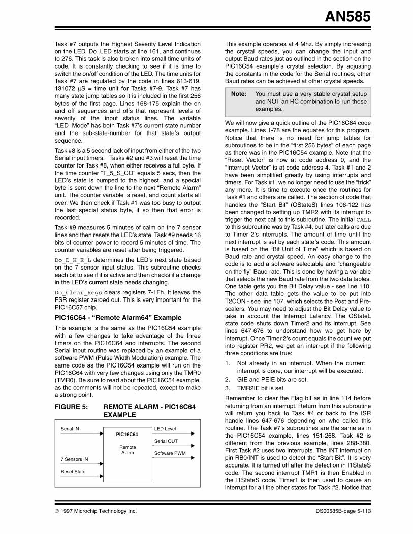
This example is the same as the PIC16C54 examplewith a few changes to take advantage of the threetimers on the PIC16C64 and interrupts. The secondSerial input routine was replaced by an example of asoftware PWM (Pulse Width Modulation) example. Thesame code as the PIC16C54 example will run on thePIC16C64 with very few changes using only the TMR0(TMR0). Be sure to read about the PIC16C54 example,as the comments will not be repeated, except to makea strong point.
FIGURE 5: REMOTE ALARM - PIC16C64 EXAMPLE
Serial IN
7 Sensors IN
Reset State
LED Level
Serial OUT
Software PWM
PIC16C64
RemoteAlarm
1997 Microchip Technology Inc.
This example operates at 4 Mhz. By simply increasingthe crystal speeds, you can change the input andoutput Baud rates just as outlined in the section on thePIC16C54 example’s crystal selection. By adjustingthe constants in the code for the Serial routines, otherBaud rates can be achieved at other crystal speeds.
We will now give a quick outline of the PIC16C64 codeexample. Lines 1-78 are the equates for this program.Notice that there is no need for jump tables forsubroutines to be in the “first 256 bytes” of each pageas there was in the PIC16C54 example. Note that the“Reset Vector” is now at code address 0, and the“Interrupt Vector” is at code address 4. Task #1 and 2have been simplified greatly by using interrupts andtimers. For Task #1, we no longer need to use the “trick”any more. It is time to execute once the routines forTask #1 and others are called. The section of code thathandles the “Start Bit” (OStateS) lines 106-122 hasbeen changed to setting up TMR2 with its interrupt totrigger the next call to this subroutine. The initial CALLto this subroutine was by Task #4, but later calls are dueto Timer 2’s interrupts. The amount of time until thenext interrupt is set by each state’s code. This amountis based on the “Bit Unit of Time” which is based onBaud rate and crystal speed. An easy change to thecode is to add a software selectable and “changeableon the fly” Baud rate. This is done by having a variablethat selects the new Baud rate from the two data tables.One table gets you the Bit Delay value - see line 110.The other data table gets the value to be put intoT2CON - see line 107, which selects the Post and Pre-scalers. You may need to adjust the Bit Delay value totake in account the Interrupt Latency. The OStateLstate code shuts down Timer2 and its interrupt. Seelines 647-676 to understand how we get here byinterrupt. Once Timer 2’s count equals the count we putinto register PR2, we get an interrupt if the followingthree conditions are true:
1. Not already in an interrupt. When the currentinterrupt is done, our interrupt will be executed.
2. GIE and PEIE bits are set.3. TMR2IE bit is set.
Remember to clear the Flag bit as in line 114 beforereturning from an interrupt. Return from this subroutinewill return you back to Task #4 or back to the ISRhandle lines 647-676 depending on who called thisroutine. The Task #7’s subroutines are the same as inthe PIC16C54 example, lines 151-268. Task #2 isdifferent from the previous example, lines 288-380.First Task #2 uses two interrupts. The INT interrupt onpin RB0/INT is used to detect the “Start Bit”. It is veryaccurate. It is turned off after the detection in I1StateScode. The second interrupt TMR1 is then Enabled inthe I1StateS code. Timer1 is then used to cause aninterrupt for all the other states for Task #2. Notice that
Note: You must use a very stable crystal setupand NOT an RC combination to run theseexamples.
DS00585B-page 5-113
AN585
Timer1 has a 16-bit counter and we calculate theamount of Clock Ticks until overflow in lines 329-333. Inthe state code I1StateL, TMR1 is shut down, and theINT interrupt is now Enabled so as to detect the nextinput byte. The initializing of the PIC16C64 variabletakes place in lines 383-426. The initializing of the taskstake place in lines 427-451. Notice that the last bit to beset is the GIE bit in line 451 after ALL is setup. Thereare several ways to execute the Task #3-9 code: byTimer0 overflow interrupt, by having the code be in thebackground as in this example. The trade-offs aremany, and too deep for this article. Notice that thesubroutine QCheck_T123 is not needed in this method.Timer0 overflow interrupt sets the flag: Time_Bit. Thecode in lines 454-457 can be considered the “IDLETask” on some systems. It waits for a Clock Tick fromTMR0’s overflow. Task #3 is new, and is a simple 8-bitsoftware PWM. Lines 459-478 show how to have 8 bitsof ON, and 8 bits of OFF. This task has two states, onand off. You may add to the code by allowing the Real-Time changing of the 8-bit values under softwarecontrol. When you change the values in the variablesPWM_Out and PWM_In, disable all interrupts by usingthe following line: BCF INTCON,GIE, and enable allinterrupts by using the following line: BSFINTCON,GIE. The new values will be used at the nexttransition, thus allowing a smooth change. This taskcould easily be used in the PIC16C54 example typeKernel. Task #4 is the same except that it calls Task#1’s subroutine to initiate the outputting of a byte. Seeline 503. Tasks #5-9 are the same as in the PIC16C54example. The subroutines: D_H_E_L andClear_Regs are the same in both examples. TheTMR0 (Timer0) Overflow interrupt ISR (Interrupt Ser-vice Routine) is lines 641-645. This ISR will set theTime_Bit bit and clear the Flag that caused the inter-rupt. The Interrupt code lines 647-676 handles the sav-ing of the Context Registers and the restoring of theContext Registers (W, Status, FSR) and by checkingthe order which interrupts are to be handled first - seelines 656-669. A very important line is 654. You mustset the memory page pointers here for the ISR rou-tines! Line 676 is the only place that an interrupt isallowed to return and set the GIE bit (RETFIE).
DS00585B-page 5-114
Reentrant example
See Appendix B for the short code segment. This codecorresponds to lines 302-332 in the PIC16C54example. The purpose of reentrant code is to allow twoor more tasks to use the same code at the “same time”.See the section about reentrant in the theory section ofthis article. Notice how the registers 18h-1Bh match theregisters 1Ch-1Fh, both starting with the state variablefor the two tasks using this routine. Note how Task #2and Task #3 load a pointer to the state variable for theirtask before calling DO_I State code. By using the FSRregister as a pointer, and incrementing or decrementingthe FSR register, you can keep the variables in the twotasks straight even if the two tasks are using differentcode in the subroutine at any one time. This method isnot easy to implement, as can be seen, so use two cop-ies for readability instead, like the PIC16C54 example.
SUMMARY
Now that the PICmicro family of microcontrollers havea way of executing Real-Time Programs, using thetechniques outlined in this article, there is very little thatPICmicros cannot do! Much more than was everdreamed before. Many of you will quickly understandand start modifying these examples. Great. Thatmeans that we have done our job at Myriad. A few ofyou may want more help. Great. At MyriadDevelopment Co., we LOVE the PICmicro family.
1997 Microchip Technology Inc.
AN585
BIBLIOGRAPHY
Foster, Caxton C.
Real Time Programming - Neglected Topics
Reading, Massachusetts
Addison-Wesley Publishing Company, 1981
Holt, R.C., Graham, G.S., Lazowska, E.D., Scott, M.A.
Structured CONCURRENT PROGRAMMING with Operating Systems Applications
Reading, Massachusetts
Addison-Wesley Publishing Company, 1978
Kaisler, Stephen H.
The Design of Operating Systems for Small Computer Systems
New York, NY
John Wiley & Sons, 1983
Labrosse, Jean J.
uC/OS - The Real-Time Kernel
Lawrence, Kansas
R & D Publications, 1992
Loeliger, R.G.
Threaded Interpretive Languages
Peterborough, NH
BYTE BOOKS, 1981
1997 Microchip Technology Inc. DS00585B-page 5-115

AN585
APPENDIX A:A Real-Time Vocabulary
ASYNCHRONOUS - An activity that can happen at any moment, at any time.
BLOCKING - The act of wanting to waiting for an EVENT before continuing.
CLOCK TICK - The heart beat that all time is based on.
CONTEXT/TASK SWITCH - Module that saves and restores the states of a task.
CRITICAL SECTION - Section of code or hardware - only one user at a time.
DEADLOCK - That is where two TASKs are waiting for each others resources.
DISPATCHING - The act of starting up a TASK to run from an RT Kernel.
DYNAMIC PRIORITIES - The ability for TASKs to have there PRIORITIES changed.
DYNAMIC TASKING - The creation and the killing of TASKs.
EMBEDDED SYSTEM - An internal system that operates all by itself.
ENABLING/DISABLING INTERRUPTS - Controlling the interrupting processing.
EVENT - Timer, communication, handshaking, interrupts, data, external events.
EVENT FLAGS - The storage of current states or info on what has happened.
INTERRUPT - A hardware event (external/internal) that triggers a jump to the ISR routines to handle that event.
INTERRUPT LATENCY - How long it takes once signaled to start an ISR.
INTERRUPT RECOVERY - How long it takes once interrupted to return back to code.
KERNEL - Module that controls TASKs, INTERRUPTs, and intertask communications.
MAILBOXES - Away to pass data from one TASK to another.
MASKABLE INTERRUPTS - The ability to control whether an ISR is called or not.
MULTITASKING - The act of several TASKs thinking they own the CPU.
MUTUAL EXCLUSION - The act of allowing only ONE owner to a RESOURCE.
NMI - NON-MASKABLE INTERRUPT - Can not be turned off by software.
READY STATE - Referring to a list of TASKs ready (having work to do NOW).
REENTRANT - Code that can be used by several TASKs at the same time.
RESOURCE - Data structures, display, I/O hardware, non-reentrant routines.
RUNNING STATE - Referring to the ONE task owning/using the CPU currently .
SCHEDULER - That part of a kernel that decides which TASK to run next.
SEMAPHORES - A protocol to control RESOURCES, SIGNAL EVENTS, synchronize tasks.
SIGNAL - The act of one task signaling another that something has happened.
STATE MACHINE - An important concept in dividing a job into TASKs & ISRs.
SYNCHRONIZATION - Were TASKs synchronize over data or at a special time.
TASK PRIORITY - Each TASK is ranked as to its importance to getting done.
TASK/THREAD - Code that is defined by a small coherent job/work to be done.
TIME SLICING - The act of giving the same amount of “time” to each TASK to run.
TRAP - A software caused interrupt, useful for system access.
WAITING STATE - Referring to a list of TASKs waiting for an EVENT(s).
DS00585B-page 5-116 1997 Microchip Technology Inc.

AN585
APPENDIX B:
MPASM 01.40 Released APP_B.ASM 1-16-1997 17:09:04 PAGE 1
LOC OBJECT CODE LINE SOURCE TEXT VALUE
00001 list p=16C54,t=ON,c=132 00002 ; 00003 ;***************************************************************** 00004 ; 00005 ; ‘Reentrant Code Example’ Designed by Myriad Development Co. - Jerry Farmer 00006 ; PIC16C54, 4MHz Crystal, WatchDog Timer OFF 00007 ; 00008 ; Program: APP_B.ASM 00009 ; Revision Date: 00010 ; 1-15-97 Compatibility with MPASMWIN 1.40 00011 ; 00012 ;******************************************************************* 00013 ; 00014 ; Register Files 00000018 00015 IState1 equ 18h ;Serial In #1 State 00000019 00016 First_TMR0_I1 equ 19h ;Starting time for next #1 Input event 0000001A 00017 nbti1 equ 1Ah ;Next Bit #1 In Time - variable time 0000001B 00018 rcv_byte_1 equ 1Bh ;Receive Serial #1 In byte 0000001C 00019 IState2 equ 1Ch ;Serial In #2 State 0000001D 00020 First_TMR0_I2 equ 1Dh ;Starting time for next #2 Input event 0000001E 00021 nbti2 equ 1Eh ;Next Bit #2 In Time - variable time 0000001F 00022 rcv_byte_2 equ 1Fh ;Receive Serial #2 In byte 00023 00024 INCLUDE <P16C5X.INC> 00001 LIST 00002 ;P16C5X.INC Standard Header File,Version 3.30 Microchip Technology,Inc. 00224 LIST 00025 00000007 00026 temp EQU 07h ;Temporary holding register - PIC16C54/56 00000010 00027 IStateS EQU 10H 00000011 00028 IStateS2 EQU 11H 00000012 00029 IState0_7 EQU 12H 00000013 00030 IStateE EQU 13H 00000014 00031 IStateL EQU 14H 00032 00033 ;****** ;Task 2,3 - Asynchronous 2400 Baud Serial Input (LOW=0)0000 00034 Do_IState 0000 0220 00035 movf INDF, F ;if IState2 == 0 0001 0643 00036 btfsc STATUS,Z ; then Do Start Bit 0002 0A10 00037 goto IStateS0003 0201 00038 movf TMR0,W ;Get current time 0004 0027 00039 movwf temp0005 02A4 00040 incf FSR, F ;Point to First_TMR0_I(1,2)0006 0200 00041 movf INDF,W ;Get elapsed time; Time Unit = 2 uS 0007 00A7 00042 subwf temp, F0008 02A4 00043 incf FSR, F ;Point to nbti(1,2)0009 0200 00044 movf INDF,W ;Past time for next input bit ? 000A 0087 00045 subwf temp,W000B 0703 00046 btfss STATUS,0000C 0A1E 00047 goto L1000D 00048 L0
Please check the Microchip BBS for the latest version of the source code. Microchip’s Worldwide Web Address: www.microchip.com; Bulletin Board Support: MCHIPBBS using CompuServe® (CompuServe membership not required).
1997 Microchip Technology Inc. DS00585B-page 5-117
AN585
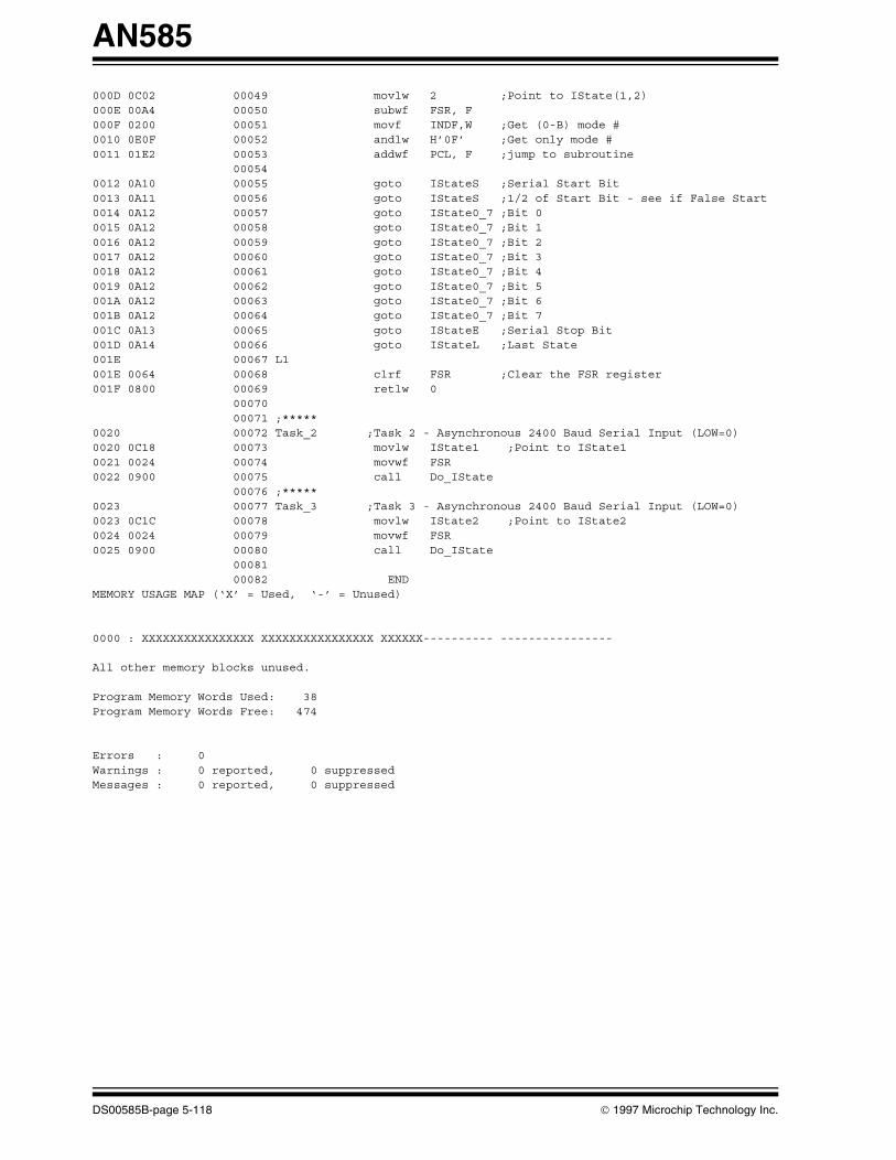
000D 0C02 00049 movlw 2 ;Point to IState(1,2) 000E 00A4 00050 subwf FSR, F000F 0200 00051 movf INDF,W ;Get (0-B) mode #0010 0E0F 00052 andlw H’0F’ ;Get only mode #0011 01E2 00053 addwf PCL, F ;jump to subroutine 00054 0012 0A10 00055 goto IStateS ;Serial Start Bit0013 0A11 00056 goto IStateS ;1/2 of Start Bit - see if False Start0014 0A12 00057 goto IState0_7 ;Bit 00015 0A12 00058 goto IState0_7 ;Bit 10016 0A12 00059 goto IState0_7 ;Bit 20017 0A12 00060 goto IState0_7 ;Bit 30018 0A12 00061 goto IState0_7 ;Bit 40019 0A12 00062 goto IState0_7 ;Bit 5001A 0A12 00063 goto IState0_7 ;Bit 6001B 0A12 00064 goto IState0_7 ;Bit 7001C 0A13 00065 goto IStateE ;Serial Stop Bit001D 0A14 00066 goto IStateL ;Last State001E 00067 L1001E 0064 00068 clrf FSR ;Clear the FSR register001F 0800 00069 retlw 0 00070 00071 ;*****0020 00072 Task_2 ;Task 2 - Asynchronous 2400 Baud Serial Input (LOW=0)0020 0C18 00073 movlw IState1 ;Point to IState10021 0024 00074 movwf FSR0022 0900 00075 call Do_IState 00076 ;*****0023 00077 Task_3 ;Task 3 - Asynchronous 2400 Baud Serial Input (LOW=0)0023 0C1C 00078 movlw IState2 ;Point to IState20024 0024 00079 movwf FSR0025 0900 00080 call Do_IState 00081 00082 ENDMEMORY USAGE MAP (‘X’ = Used, ‘-’ = Unused)
0000 : XXXXXXXXXXXXXXXX XXXXXXXXXXXXXXXX XXXXXX---------- ----------------
All other memory blocks unused.
Program Memory Words Used: 38Program Memory Words Free: 474
Errors : 0Warnings : 0 reported, 0 suppressedMessages : 0 reported, 0 suppressed
DS00585B-page 5-118 1997 Microchip Technology Inc.

AN585
APPENDIX C:MPASM 01.40 Released APP_C.ASM 1-16-1997 17:09:32 PAGE 1
LOC OBJECT CODE LINE SOURCE TEXT VALUE
00001 ;‘Remote Alarm’ V1.02 00002 ; Designed by Myriad Development Co/- Jerry Farmer 00003 ; PIC16C54, 4MHz Crystal, 00004 ; WatchDog Timer OFF, MPASM instruction set 00005 ; 00006 ; Program: APP_C.ASM 00007 ; Revision Date: 00008 ; 1-15-97 Compatibility with MPASMWIN 1.40 00009 ; 00010 ;***************************************************************** 00011 ; 00012 list p=16C54,t=ON,c=132 00013 00014 include “P16C5X.INC” 00001 LIST 00002 ;P16C5X.INC Standard Header File, Ver. 3.30 Microchip Technology,Inc. 00224 LIST 00015 00016 ; Constants 00000000 00017 INDIR equ 0 ;Indirect Register 00000033 00018 OUT_BIT_TIME equ 33h ;9600 Baud, 104uS Bit Rate 00000064 00019 IN_BIT_TIME equ 64h ;4800 Baud, 208uS Bit Rate 00000023 00020 FUDGE_TIME equ 23h ;Current Time within a Fudge Factor 00021 00022 ; B Register Definitions 00023 #define Level_Reset PORTB, ;Low will cause Past Level to reset 00024 ;RB.7 - RB.1 == Input from Sensors 000000FF 00025 RB_TRIS equ B’11111111’ ;RB TRIS at INIT State == all input 00000000 00026 RB_MASK equ B’00000000’ ;What is High/Low for RB at INIT State 00027 00028 ; A Register Definitions - Programmable Inputs 00029 #define Serial_IN_1 PORTA,0 ;Serial Input #1 - 8 bits 00030 #define LED PORTA,1 ;LED Output - Level/State Indicator 00031 #define Serial_Out PORTA,2 ;Serial Output - 8 bits + passwords 00032 #define Serial_IN_2 PORTA,3 ;Serial Input #2 - 8 bits 00033 000000F9 00034 RA_TRIS equ B’11111001’ ;RA TRIS at INIT State 00000000 00035 RA_MASK equ B’00000000’ ;What is High/Low for RA at INIT State 00036 00037 ; Register Files 00000007 00038 temp equ 07h ;Temporary holding register - PIC16C54/56 00000008 00039 Timer_Bits equ 08h ;Indicates which Timer(s) are Active = 1 00000009 00040 Flags equ 09h ;Error Flags 0000000A 00041 LED_Mode equ 0Ah ;(0-2)=Mode, 3=LED_B, (4-6)=Seq #, 7=NEW 0000000B 00042 OState equ 0Bh ;Serial Out State 0000000C 00043 T_5_M_LO equ 0Ch ;5 Min Timer Counter - Low 0000000D 00044 T_5_M_HI equ 0Dh ;5 Min Timer Counter - High 0000000E 00045 T_5_S_CO equ 0Eh ;5 Second Timer - lack of Serial Input 0000000F 00046 T_20_mS_CO equ 0Fh ;20 mS Timer - used for debouncing 00000010 00047 LED_C equ 10h ;LED Counter 00000011 00048 Last_TMR0 equ 11h ;Last value of the TMR0 00000012 00049 First_TMR0_O equ 12h ;Starting time for next Output event 00000013 00050 xmt_byte equ 13h ;Serial xmit byte - destroyed in use 00000014 00051 cc equ 14h ;256 * TMR0 time
Please check the Microchip BBS for the latest version of the source code. Microchip’s Worldwide Web Address: www.microchip.com; Bulletin Board Support: MCHIPBBS using CompuServe® (CompuServe membership not required).
1997 Microchip Technology Inc. DS00585B-page 5-119
AN585
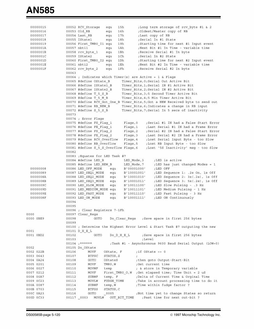
00000015 00052 RCV_Storage equ 15h ;Long term storage of rcv_byte #1 & 2 00000016 00053 Old_RB equ 16h ;Oldest/Master copy of RB 00000017 00054 Last_RB equ 17h ;Last copy of RB 00000018 00055 IState1 equ 18h ;Serial In #1 State 00000019 00056 First_TMR0_I1 equ 19h ;Starting time for next #1 Input event 0000001A 00057 nbti1 equ 1Ah ;Next Bit #1 In Time - variable time 0000001B 00058 rcv_byte_1 equ 1Bh ;Receive Serial #1 In byte 0000001C 00059 IState2 equ 1Ch ;Serial In #2 State 0000001D 00060 First_TMR0_I2 equ 1Dh ;Starting time for next #2 Input event 0000001E 00061 nbti2 equ 1Eh ;Next Bit #2 In Time - variable time 0000001F 00062 rcv_byte_2 equ 1Fh ;Receive Serial #2 In byte 00063 00064 ; Indicates which Timer(s) are Active = 1 & Flags 00065 #define OState_B Timer_Bits,0;Serial Out Active Bit 00066 #define IState1_B Timer_Bits,1;Serial IN #1 Active Bit 00067 #define IState2_B Timer_Bits,2;Serial IN #2 Active Bit 00068 #define T_5_S_B Timer_Bits,3;5 Second Timer Active Bit 00069 #define T_5_M_B Timer_Bits,4;5 Min Timer Active Bit 00070 #define RCV_Got_One_B Timer_Bits,5;Got a NEW Received byte to send out 00071 #define RB_NEW_B Timer_Bits,6;Indicates a change in RB input 00072 #define S_5_S_B Timer_Bits,7;Serial In 5 secs of inactivity 00073 00074 ; Error Flags 00075 #define FS_Flag_1 Flags,0 ;Serial #1 IN had a False Start Error 00076 #define FE_Flag_1 Flags,1 ;Last Serial #1 IN had a Frame Error 00077 #define FS_Flag_2 Flags,2 ;Serial #2 IN had a False Start Error 00078 #define FE_Flag_2 Flags,3 ;Last Serial #2 IN had a Frame Error 00079 #define RCV_Overflow Flags,4 ;Lost Serial Input Byte - too Slow 00080 #define RB_Overflow Flags,5 ;Lost RB Input Byte - too Slow 00081 #define S_5_S_Overflow Flags,6 ;Lost ‘5S Inactivity’ msg - too Slow 00082 00083 ;Equates for LED Task #7 00084 #define LED_B LED_Mode,3 ;LED is active 00085 #define LED_NEW_B LED_Mode,7 ;LED has just changed Modes = 1 00000008 00086 LED_OFF_MODE equ B’00001000’ ;LED OFF 00000089 00087 LED_SEQ1_MODE equ B’10001001’ ;LED Sequence 1: .2s On, 1s Off 0000008A 00088 LED_SEQ2_MODE equ B’10001010’ ;LED Sequence 2: 3x(.2s), 1s Off 0000008B 00089 LED_SEQ3_MODE equ B’10001011’ ;LED Sequence 3: 5x(.2s), 1s Off 0000009C 00090 LED_SLOW_MODE equ B’10011100’ ;LED Slow Pulsing - .3 Hz 0000009D 00091 LED_MEDIUM_MODE equ B’10011101’ ;LED Medium Pulsing - 1 Hz 0000009E 00092 LED_FAST_MODE equ B’10011110’ ;LED Fast Pulsing - 3 Hz 0000008F 00093 LED_ON_MODE equ B’10001111’ ;LED ON Continuously 00094 00095 00096 ; Clear Registers 7-1Fh 0000 00097 Clear_Regs 0000 0BE9 00098 GOTO Do_Clear_Regs ;Save space in first 256 bytes 00099 00100 ; Determine the Highest Error Level & Start Task #7 outputing the new 0001 00101 D_H_E_L 0001 0BD2 00102 GOTO Do_D_H_E_L ;Save space in first 256 bytes 00103 ;Level 00104 ;****** ;Task #1 - Asynchronous 9600 Baud Serial Output (LOW=0)0002 00105 Do_OState 0002 022B 00106 MOVF OState, F ;if OState == 0 0003 0643 00107 BTFSC STATUS,Z ; 0004 0A24 00108 GOTO OStateS ;then goto Output-Start-Bit0005 0201 00109 MOVF TMR0,W ;Get current time 0006 0027 00110 MOVWF temp ; & store in Temporary variable0007 0212 00111 MOVF First_TMR0_O,W ;Get elapsed time; Time Unit = 2 uS 0008 00A7 00112 SUBWF temp, F ;Delta of Current Time & Orginal Time0009 0C23 00113 MOVLW FUDGE_TIME ;Take in account processing time to do it000A 0087 00114 SUBWF temp,W ;Time within fudge factor ? 000B 0703 00115 BTFSS STATUS,C000C 0A23 00116 GOTO _0005 ;Not time yet to change States so return000D 0C33 00117 _0003 MOVLW OUT_BIT_TIME ;Past time for next out-bit ?
DS00585B-page 5-120 1997 Microchip Technology Inc.

AN585
000E 0087 00118 SUBWF temp,W 000F 0603 00119 BTFSC STATUS,C ;Do some delaying until it is time0010 0A15 00120 GOTO _0004 ;It is now time to out put a bit0011 0C04 00121 MOVLW H’04’ ;Account for loop delay 0012 01E7 00122 ADDWF temp, F0013 0000 00123 NOP ; make loop delay even0014 0A0D 00124 GOTO _0003 ;Wait for exact time to output bit0015 020B 00125 _0004 MOVF OState,W ;Get (0-A) mode #0016 0E0F 00126 ANDLW H’0F’ ;Get only mode # 0017 01E2 00127 ADDWF PCL, F ;jump to subroutine0018 0A24 00128 GOTO OStateS ;Serial Start Bit0019 0A2B 00129 GOTO OState0_7 ;Bit 0 001A 0A2B 00130 GOTO OState0_7 ;Bit 1 001B 0A2B 00131 GOTO OState0_7 ;Bit 2 001C 0A2B 00132 GOTO OState0_7 ;Bit 3 001D 0A2B 00133 GOTO OState0_7 ;Bit 4 001E 0A2B 00134 GOTO OState0_7 ;Bit 5 001F 0A2B 00135 GOTO OState0_7 ;Bit 6 0020 0A2B 00136 GOTO OState0_7 ;Bit 7 0021 0A31 00137 GOTO OStateE ;Serial Stop Bit0022 0A36 00138 GOTO OStateL ;Last State 0023 0800 00139 _0005 RETLW H’00’ 00140 0024 00141 OStateS 0024 0545 00142 BSF Serial_Out ;Serial Start Bit 0025 0201 00143 MOVF TMR0,W ;Store starting time 0026 0032 00144 MOVWF First_TMR0_O0027 0C0D 00145 MOVLW H’0D’ ;Fudge again 0028 00B2 00146 SUBWF First_TMR0_O, F0029 02AB 00147 INCF OState, F ;increment to next state 002A 0800 00148 RETLW H’00’ 00149 002B 00150 OState0_7 ;Bit 0 - 7 002B 0333 00151 RRF xmt_byte, F ;Move bit into C from right most bit 002C 0703 00152 BTFSS STATUS,C ; 002D 0445 00153 BCF Serial_Out ;002E 0603 00154 BTFSC STATUS,C ;002F 0545 00155 BSF Serial_Out ;0030 0A32 00156 GOTO OS_End0031 00157 OStateE 0031 0445 00158 BCF Serial_Out ;Serial Stop Bit 0032 0C33 00159 OS_End MOVLW OUT_BIT_TIME ;Adjust out the cumulation of error 0033 01F2 00160 ADDWF First_TMR0_O, F0034 02AB 00161 INCF OState, F ;increment to next state 0035 0800 00162 RETLW H’00’0036 00163 OStateL 0036 006B 00164 CLRF OState ;Ready to send next byte out 0037 0408 00165 BCF OState_B ;Serial Out not active 0038 0800 00166 RETLW H’00’ 00167 00168 ;****** ;Task #7 - Output Highest Level Indication on LED 0039 00169 Do_LED 0039 06EA 00170 BTFSC LED_NEW_B ;Initialize regs if change in modes 003A 0A4C 00171 GOTO LED_NEW003B 02B0 00172 INCF LED_C, F ;Inc Counter - Time Unit = 131072 uS 003C 020A 00173 MOVF LED_Mode,W ;Get (0-7) mode # 003D 0E07 00174 ANDLW H’07’ ;Get only mode #003E 01E2 00175 ADDWF PCL, F ;jump to subroutine 003F 0A48 00176 GOTO LED_OFF ;LED OFF 0040 0A64 00177 GOTO LED_SEQ1 ;LED Seq 1: 1 short pulse & pause 0041 0A67 00178 GOTO LED_SEQ2 ;LED Seq 2: 2 short pulses & pause0042 0A8A 00179 GOTO LED_SEQ3 ;LED Seq 3: 3 short pulses & pause 0043 0A50 00180 GOTO LED_SLOW ;LED Slow Pulsing - .3 Hz 0044 0A5E 00181 GOTO LED_MEDIUM ;LED Medium Pulsing - 1 Hz0045 0A61 00182 GOTO LED_FAST ;LED Fast Pulsing - 3 Hz 0046 0A4D 00183 GOTO LED_ON ;LED ON Continuously
1997 Microchip Technology Inc. DS00585B-page 5-121

AN585
0047 0800 00184 _0012 RETLW H’00’ 00185 ;------0048 00186 LED_OFF 0048 0425 00187 BCF LED ;Turn off LED 0049 046A 00188 BCF LED_B ;LED must be off 004A 0070 00189 CLRF LED_C ;Reset Counter - LED_C = 0 004B 0800 00190 RETLW H’00’ 00191 ;------004C 00192 LED_NEW 004C 04EA 00193 BCF LED_NEW_B ;Done initializing004D 00194 LED_ON 004D 0525 00195 BSF LED ;Turn on LED004E 0070 00196 CLRF LED_C ;Reset Counter - LED_C = 0 004F 0800 00197 RETLW H’00’ 00198 ;------0050 00199 LED_SLOW 0050 0C0C 00200 MOVLW H’0C’ ;.3Hz @ 50% Duty 0051 0027 00201 MOVWF temp0052 0207 00202 LED_S MOVF temp,W ;Check LED_C if time, .3Hz @ 50% Duty 0053 0090 00203 SUBWF LED_C,W0054 0743 00204 BTFSS STATUS,Z0055 0A47 00205 GOTO _00120056 0C10 00206 MOVLW H’10’0057 01AA 00207 XORWF LED_Mode, F ;Switch states 0058 078A 00208 BTFSS LED_Mode,4 ;Now make LED same state0059 0425 00209 BCF LED005A 068A 00210 BTFSC LED_Mode,4005B 0525 00211 BSF LED005C 0070 00212 CLRF LED_C ;Reset LED_C005D 0800 00213 RETLW H’00’ 00214 ;------005E 00215 LED_MEDIUM 005E 0C04 00216 MOVLW H’04’ ;1Hz @ 50% Duty 005F 0027 00217 MOVWF temp 0060 0A52 00218 GOTO LED_S ;Go do it 00219 ;------0061 00220 LED_FAST 0061 0C01 00221 MOVLW H’01’ ;3Hz @ 50% Duty 0062 0027 00222 MOVWF temp0063 0A52 00223 GOTO LED_S ;Go do it 00224 ;------0064 00225 LED_SEQ1 ;.2 ON, 1 OFF 0064 078A 00226 BTFSS LED_Mode,4 ;Skip if bit is high 0065 0A76 00227 GOTO ON1 ;Go do it 0066 0A82 00228 GOTO OFF3 ;Go do it 00229 ;------0067 00230 LED_SEQ2 ;.2 ON, .2 OFF, .2 ON, 1 OFF 0067 020A 00231 MOVF LED_Mode,W0068 0027 00232 MOVWF temp0069 0C30 00233 MOVLW H’30’ ;Get sequence # only 006A 0167 00234 ANDWF temp, F006B 03A7 00235 SWAPF temp, F ;swap nibbles 006C 0207 00236 MOVF temp,W ;get nibble for offset 006D 01E2 00237 ADDWF PCL, F ;Table jump calculation 006E 0A76 00238 GOTO ON1 ;LED is on, check if time to change 006F 0A7C 00239 GOTO OFF2 ;LED is off, check if time to change0070 0A76 00240 GOTO ON1 ;LED is on, check if time to change 0071 0A82 00241 GOTO OFF3 ;LED is off, check if time to change 00242 ;------0072 00243 LED_Exit 0072 0C10 00244 MOVLW H’10’ ;Inc Seq # 0073 01EA 00245 ADDWF LED_Mode, F0074 0070 00246 CLRF LED_C ;Reset LED_C 0075 0800 00247 RETLW H’00’0076 00248 ON1 0076 0C02 00249 MOVLW H’02’ ;Check LED_C if time, .2 sec-on
DS00585B-page 5-122 1997 Microchip Technology Inc.

AN585
0077 0090 00250 SUBWF LED_C,W0078 0743 00251 BTFSS STATUS,Z0079 0A47 00252 GOTO _0012007A 0425 00253 BCF LED ;Turn off LED 007B 0A72 00254 GOTO LED_Exit007C 00255 OFF2 007C 0C02 00256 MOVLW H’02’ ;Check LED_C if time, .2 sec-on007D 0090 00257 SUBWF LED_C,W007E 0743 00258 BTFSS STATUS,Z007F 0A47 00259 GOTO _00120080 0525 00260 BSF LED ;Turn on LED 0081 0A72 00261 GOTO LED_Exit0082 00262 OFF3 0082 0C08 00263 MOVLW H’08’ ;Check LED_C if time, 1 sec-off 0083 0090 00264 SUBWF LED_C,W0084 0743 00265 BTFSS STATUS,Z0085 0A47 00266 GOTO _00120086 0525 00267 BSF LED ;Turn on LED 0087 0CF0 00268 MOVLW H’F0’0088 012A 00269 IORWF LED_Mode, F ;Cause (Seq# & NEW) to overflow to 00089 0A72 00270 GOTO LED_Exit008A 00271 LED_SEQ3 ;.2 ON, .2 OFF, .2 ON, .2 OFF, .2 ON, 1 OFF 008A 020A 00272 MOVF LED_Mode,W ;Get LED info 008B 0027 00273 MOVWF temp008C 0C70 00274 MOVLW H’70’ ;Get sequence # only 008D 0167 00275 ANDWF temp, F 008E 03A7 00276 SWAPF temp, F ;swap nibbles008F 0207 00277 MOVF temp,W ;get nibble for offset 0090 01E2 00278 ADDWF PCL, F ;Table jump calculation 0091 0A76 00279 GOTO ON1 ;LED is on check if time to change 0092 0A7C 00280 GOTO OFF2 ;LED is off check if time to change 0093 0A76 00281 GOTO ON1 ;LED is on check if time to change0094 0A7C 00282 GOTO OFF2 ;LED is off check if time to change 0095 0A76 00283 GOTO ON1 ;LED is on check if time to change0096 0A82 00284 GOTO OFF3 ;LED is off check if time to change 00285 00286 ;**** Quick Check of Tasks #1, #2 and #30097 00287 QCheck_T123 00288 ;Task #1 - Asynchronous 9600 Baud Serial Output (LOW=0)0097 0708 00289 BTFSS OState_B ;if not outputing now then skip call0098 0A9A 00290 GOTO T20099 0902 00291 CALL Do_OState ;Go Do Task #1 00292 00293 ;Task #2 - Asynchronous 4800 Baud Serial Input (LOW=0) 009A 0628 00294 T2 BTFSC IState1_B ;if already started then call009B 0A9F 00295 GOTO _0029009C 0605 00296 BTFSC Serial_IN_1 ;if Start bit ? then call 009D 0A9F 00297 GOTO _0029009E 0AA0 00298 GOTO T3009F 09A7 00299 _0029 CALL Do_I1State ;Go Do Task #2 00300 00301 ;Task #3 - Asynchronous 4800 Baud Serial Input (LOW=0)00A0 0648 00302 T3 BTFSC IState2_B ;if already started then call00A1 0AA5 00303 GOTO _003100A2 0665 00304 BTFSC Serial_IN_2 ;if Start bit ? then call 00A3 0AA5 00305 GOTO _003100A4 0800 00306 RETLW H’00’00A5 09C2 00307 _0031 CALL Do_I2State ;Go Do Task #300A6 0800 00308 RETLW H’00’ 00309 00310 ;****** ;Task #2 - Asynchronous 4800 Baud Serial Input (LOW=0)00A7 00311 Do_I1State 00A7 0238 00312 MOVF IState1, F ;if IState1 == 0 00A8 0643 00313 BTFSC STATUS,Z ; then Do Start Bit 00A9 0ADD 00314 GOTO I1StateS00AA 0201 00315 MOVF TMR0,W ;Get current time
1997 Microchip Technology Inc. DS00585B-page 5-123

AN585
00AB 0027 00316 MOVWF temp00AC 0219 00317 MOVF First_TMR0_I1,W ;Get elapsed time; Time Unit = 2 uS 00AD 00A7 00318 SUBWF temp, F00AE 021A 00319 MOVF nbti1,W ;Past time for next input bit ? 00AF 0087 00320 SUBWF temp,W00B0 0703 00321 BTFSS STATUS,C00B1 0AC1 00322 GOTO _003300B2 0218 00323 MOVF IState1,W ;Get (0-B) mode #00B3 0E0F 00324 ANDLW H’0F’ ;Get only mode # 00B4 01E2 00325 ADDWF PCL, F ;jump to subroutine00B5 0ADD 00326 GOTO I1StateS ;Serial Start Bit 00B6 0AE6 00327 GOTO I1State2 ;1/2 of Start Bit - see if False Start00B7 0AEF 00328 GOTO I1State0_7 ;Bit 0 00B8 0AEF 00329 GOTO I1State0_7 ;Bit 1 00B9 0AEF 00330 GOTO I1State0_7 ;Bit 2 00BA 0AEF 00331 GOTO I1State0_7 ;Bit 3 00BB 0AEF 00332 GOTO I1State0_7 ;Bit 4 00BC 0AEF 00333 GOTO I1State0_7 ;Bit 5 00BD 0AEF 00334 GOTO I1State0_7 ;Bit 6 00BE 0AEF 00335 GOTO I1State0_7 ;Bit 7 00BF 0AF8 00336 GOTO I1StateE ;Serial Stop Bit 00C0 0B03 00337 GOTO I1StateL ;Last State - End of Stop Bit00C1 00338 _0033 00C1 0800 00339 RETLW H’00’ 00340 00341 ;****** ;Task #3 - Asynchronous 4800 Baud Serial Input (LOW=0)00C2 00342 Do_I2State 00C2 023C 00343 MOVF IState2, F ;if IState1 == 000C3 0643 00344 BTFSC STATUS,Z ;then Do Start Bit 00C4 0B10 00345 GOTO I2StateS00C5 0201 00346 MOVF TMR0,W ;Get current time00C6 0027 00347 MOVWF temp00C7 021D 00348 MOVF First_TMR0_I2,W ;Get elapsed time; Time Unit = 2 uS00C8 00A7 00349 SUBWF temp, F00C9 021E 00350 MOVF nbti2,W ;Past time for next input bit ? 00CA 0087 00351 SUBWF temp,W00CB 0703 00352 BTFSS STATUS,C00CC 0ADC 00353 GOTO _003500CD 021C 00354 MOVF IState2,W ;Get (0-B) mode #00CE 0E0F 00355 ANDLW H’0F’ ;Get only mode # 00CF 01E2 00356 ADDWF PCL, F ;jump to subroutine 00D0 0B10 00357 GOTO I2StateS ;Serial Start Bit 00D1 0B19 00358 GOTO I2StateS2 ;1/2 of Start Bit - see if False Start00D2 0B22 00359 GOTO I2State0_7 ;Bit 000D3 0B22 00360 GOTO I2State0_7 ;Bit 100D4 0B22 00361 GOTO I2State0_7 ;Bit 200D5 0B22 00362 GOTO I2State0_7 ;Bit 300D6 0B22 00363 GOTO I2State0_7 ;Bit 400D7 0B22 00364 GOTO I2State0_7 ;Bit 500D8 0B22 00365 GOTO I2State0_7 ;Bit 600D9 0B22 00366 GOTO I2State0_7 ;Bit 700DA 0B2B 00367 GOTO I2StateE ;Serial Stop Bit 00DB 0B36 00368 GOTO I2StateL ;Last State - End of Stop Bit 00DC 0800 00369 _0035 RETLW H’00’ 00370 00371 ;*** ;Subroutines for Task #200DD 00372 I1StateS ;Start Bit - Setup timing variables00DD 0528 00373 BSF IState1_B ;Serial Input Active 00DE 0201 00374 MOVF TMR0,W ;Store starting time00DF 0039 00375 MOVWF First_TMR0_I100E0 0C0D 00376 MOVLW H’0D’ ;Fudge again 00E1 00B9 00377 SUBWF First_TMR0_I1, F00E2 0C32 00378 MOVLW H’32’ ;Time delay = 1/2 bit time 00E3 003A 00379 MOVWF nbti100E4 02B8 00380 INCF IState1, F ;Increment to next state 00E5 0800 00381 RETLW H’00’
DS00585B-page 5-124 1997 Microchip Technology Inc.

AN585
00E6 00382 I1State2 ;Check if still a Start Bit00E6 0705 00383 BTFSS Serial_IN_1 ;False Start Error ? 00E7 0B06 00384 GOTO FS_Error_100E8 0409 00385 BCF FS_Flag_1 ;Start Bit OK 00E9 021A 00386 MOVF nbti1,W ;Adjust out the error00EA 01F9 00387 ADDWF First_TMR0_I1, F00EB 0C64 00388 MOVLW IN_BIT_TIME ;Time Delay = full bit time00EC 003A 00389 MOVWF nbti100ED 02B8 00390 INCF IState1, F ;increment to next state00EE 0800 00391 RETLW H’00’00EF 00392 I1State0_7 ;Bit 0 - 7 00EF 0705 00393 BTFSS Serial_IN_1 ;Move Input bit into C 00F0 0403 00394 BCF STATUS,C00F1 0605 00395 BTFSC Serial_IN_100F2 0503 00396 BSF STATUS,C00F3 033B 00397 RRF rcv_byte_1, F ;Move C into left most bit 00F4 021A 00398 MOVF nbti1,W00F5 01F9 00399 ADDWF First_TMR0_I1, F ;Adjust out the error00F6 02B8 00400 INCF IState1, F ;increment to next state 00F7 0800 00401 RETLW H’00’00F8 00402 I1StateE ;Check if we have a proper Stop Bit00F8 0605 00403 BTFSC Serial_IN_1 ;Frame Error00F9 0B09 00404 GOTO F_Error_100FA 0429 00405 BCF FE_Flag_1 ;Stop Bit OK00FB 006E 00406 CLRF T_5_S_CO ;Reset 5 Sec Timer - got a good byte 00407 ;Process the msg Here !00FC 021B 00408 MOVF rcv_byte_1,W ;Make a copy of just received byte 00FD 0035 00409 MOVWF RCV_Storage00FE 07A8 00410 BTFSS RCV_Got_One_B ;Report Lost data 00FF 0489 00411 BCF RCV_Overflow0100 06A8 00412 BTFSC RCV_Got_One_B0101 0589 00413 BSF RCV_Overflow0102 05A8 00414 BSF RCV_Got_One_B ;We Now have a RB Value to go out 0103 00415 I1StateL 0103 0078 00416 CLRF IState1 ;Ready to receive next byte0104 0428 00417 BCF IState1_B ;Serial In not currently active0105 0800 00418 RETLW H’00’0106 00419 FS_Error_1 ;False Start - Shut Down Checking0106 0428 00420 BCF IState1_B ;Serial Input NOT Active0107 0509 00421 BSF FS_Flag_1 ;False Start Error 0108 0B03 00422 GOTO I1StateL ;Start All Over 0109 00423 F_Error_1 ;Frame Error - Wait for End of Stop Bit 0109 021A 00424 MOVF nbti1,W ;Adjust out the error010A 01F9 00425 ADDWF First_TMR0_I1, F010B 0C32 00426 MOVLW H’32’ ;Time Delay = 1/2 bit time010C 003A 00427 MOVWF nbti1010D 0529 00428 BSF FE_Flag_1 ;Frame Error for this Byte ?010E 02B8 00429 INCF IState1, F ;Increment to next state010F 0800 00430 RETLW H’00’ 00431 00432 ;*** ;Subroutines for Task #30110 00433 I2StateS ;Start Bit - Setup timing variables0110 0548 00434 BSF IState2_B ;Serial Input Active 0111 0201 00435 MOVF TMR0,W ;Store starting time 0112 003D 00436 MOVWF First_TMR0_I20113 0C0D 00437 MOVLW H’0D’ ;Fudge again 0114 00BD 00438 SUBWF First_TMR0_I2, F0115 0C32 00439 MOVLW H’32’ ;Time delay = 1/2 bit time0116 003E 00440 MOVWF nbti20117 02BC 00441 INCF IState2, F ;Increment to next state0118 0800 00442 RETLW H’00’0119 00443 I2StateS2 ;Check if still a Start Bit0119 0765 00444 BTFSS Serial_IN_2 ;False Start Error ? 011A 0B39 00445 GOTO FS_Error_2011B 0449 00446 BCF FS_Flag_2 ;Start Bit OK 011C 021E 00447 MOVF nbti2,W ;Adjust out the error
1997 Microchip Technology Inc. DS00585B-page 5-125

AN585
011D 01FD 00448 ADDWF First_TMR0_I2, F011E 0C64 00449 MOVLW IN_BIT_TIME ;Time Delay = full bit time 011F 003E 00450 MOVWF nbti20120 02BC 00451 INCF IState2, F ;increment to next state0121 0800 00452 RETLW H’00’0122 00453 I2State0_7 ;Bit 0 - 7 0122 0765 00454 BTFSS Serial_IN_2 ;Move Input bit into C0123 0403 00455 BCF STATUS,C0124 0665 00456 BTFSC Serial_IN_20125 0503 00457 BSF STATUS,C0126 033F 00458 RRF rcv_byte_2, F ;Move C into left most bit 0127 021E 00459 MOVF nbti2,W0128 01FD 00460 ADDWF First_TMR0_I2, F ;Adjust out the error 0129 02BC 00461 INCF IState2, F ;increment to next state 012A 0800 00462 RETLW H’00’012B 00463 I2StateE ;Check if we have a proper Stop Bit012B 0665 00464 BTFSC Serial_IN_2 ;Frame Error012C 0B3C 00465 GOTO F_Error_2012D 0469 00466 BCF FE_Flag_2 ;Stop Bit OK 012E 006E 00467 CLRF T_5_S_CO ;Reset 5 Sec Timer - got a good byte 00468 ;Process the msg Here !012F 021F 00469 MOVF rcv_byte_2,W ;Make a copy of just received byte 0130 0035 00470 MOVWF RCV_Storage0131 07A8 00471 BTFSS RCV_Got_One_B ;Report Lost data 0132 0489 00472 BCF RCV_Overflow0133 06A8 00473 BTFSC RCV_Got_One_B0134 0589 00474 BSF RCV_Overflow0135 05A8 00475 BSF RCV_Got_One_B ;We Now have a RB Value to go out 0136 00476 I2StateL 0136 007C 00477 CLRF IState2 ;Ready to receive next byte 0137 0448 00478 BCF IState2_B ;Serial In not currently active 0138 0800 00479 RETLW H’00’0139 00480 FS_Error_2 0139 0448 00481 BCF IState2_B ;False Start - Shut Down Checking013A 0549 00482 BSF FS_Flag_2 ;False Start Error 013B 0B36 00483 GOTO I2StateL ;Start All Over013C 00484 F_Error_2 ;Frame Error - Wait for End of Stop Bit013C 021E 00485 MOVF nbti2,W ;Adjust out the error 013D 01FD 00486 ADDWF First_TMR0_I2, F013E 0C32 00487 MOVLW H’32’ ;Time Delay = 1/2 bit time 013F 003E 00488 MOVWF nbti20140 0569 00489 BSF FE_Flag_2 ;Frame Error for this Byte ? 0141 02BC 00490 INCF IState2, F ;Increment to next state 0142 0800 00491 RETLW H’00’ 00492 00493 ;****** ;Code Starting point0143 00494 Main 0143 0C00 00495 MOVLW H’00’ ;What is High/Low for RA at INIT State 0144 0025 00496 MOVWF PORTA0145 0C00 00497 MOVLW H’00’ ;What is High/Low for RB at INIT State 0146 0026 00498 MOVWF PORTB0147 0CF9 00499 MOVLW H’F9’ ;RA TRIS at INIT State 0148 0005 00500 TRIS 50149 0CFF 00501 MOVLW H’FF’ ;RB TRIS at INIT State 014A 0006 00502 TRIS 6014B 0C00 00503 MOVLW H’00’ ;TMR0/2 014C 0002 00504 OPTION014D 0900 00505 CALL Clear_Regs ;Clear Registers 7-1F - Same Memory Page014E 0061 00506 CLRF TMR0 ;Start timers 00507 00508 ;Initialize Tasks 00509 ;Task #1 waits for byte to output 00510 ;Task #2 waits for Serial IN Start Bit 00511 ;Task #3 waits for Serial IN Start Bit 00512 ;Task #4 runs when Task 1 is Not 00513 ;Task #5 is always running
DS00585B-page 5-126 1997 Microchip Technology Inc.

AN585
014F 0206 00514 MOVF PORTB,W ;Task #6 is Initialized here 0150 0036 00515 MOVWF Old_RB0151 0216 00516 MOVF Old_RB,W ;Make all the same initial value 0152 0037 00517 MOVWF Last_RB0153 05C8 00518 BSF RB_NEW_B ;Tell Task #4: RB byte ready to output0154 0C08 00519 MOVLW LED_OFF_MODE0155 002A 00520 MOVWF LED_Mode ;Task #7 is Started 0156 0568 00521 BSF T_5_S_B ;Task #8 is Started here 0157 0588 00522 BSF T_5_M_B ;Task #9 is Started here 00523 00524 ; Handle Task & Timer activities - Main Loop0158 00525 Task_1 ;Task #1 - Asynchronous 9600 Baud Serial Output (LOW=0)0158 0708 00526 BTFSS OState_B ;if not outputing now then skip call 0159 0B5B 00527 GOTO Task_2015A 0902 00528 CALL Do_OState ;Go Do Task #1 00529 015B 00530 Task_2 ;Task #2 - Asynchronous 4800 Baud Serial Input (LOW=0)015B 0628 00531 BTFSC IState1_B ;if already started then call015C 0B60 00532 GOTO _0053015D 0605 00533 BTFSC Serial_IN_1 ;if Start bit ? then call015E 0B60 00534 GOTO _0053015F 0B61 00535 GOTO Task_30160 09A7 00536 _0053 CALL Do_I1State ;Go Do Task #2 00537 0161 00538 Task_3 ;Task #3 - Asynchronous 4800 Baud Serial Input (LOW=0)0161 0648 00539 BTFSC IState2_B ;if already started then call 0162 0B66 00540 GOTO _00550163 0665 00541 BTFSC Serial_IN_2 ;if Start bit ? then call 0164 0B66 00542 GOTO _00550165 0B67 00543 GOTO Task_40166 09C2 00544 _0055 CALL Do_I2State ;Go Do Task #3 00545 0167 00546 Task_4 ;Task #4 - Finds next Buffered Byte to Send Out through Task 10167 0608 00547 BTFSC OState_B ;if outputing now then skip call0168 0B7D 00548 GOTO _00590169 07A8 00549 BTFSS RCV_Got_One_B ;Got a NEW Received byte to send016A 0B70 00550 GOTO _0057016B 0215 00551 MOVF RCV_Storage,W ;Send just received byte 016C 0033 00552 MOVWF xmt_byte016D 04A8 00553 BCF RCV_Got_One_B ;Clear need to send old byte 016E 0508 00554 BSF OState_B ;Start Task #1 & Lock Out Others 016F 0B7D 00555 GOTO _00590170 07C8 00556 _0057 BTFSS RB_NEW_B ;Indicates a change in RB input 0171 0B77 00557 GOTO _00580172 0216 00558 MOVF Old_RB,W ;Send New RB value 0173 0033 00559 MOVWF xmt_byte0174 04C8 00560 BCF RB_NEW_B ;Clear need to send out newest value 0175 0508 00561 BSF OState_B ;Start Task #1 & Lock Out Others0176 0B7D 00562 GOTO _00590177 07E8 00563 _0058 BTFSS S_5_S_B ;Serial In 5 secs of inactivity0178 0B7D 00564 GOTO _00590179 0CFF 00565 MOVLW H’FF’ ;Tell of inactivity of Serial In 017A 0033 00566 MOVWF xmt_byte017B 04E8 00567 BCF S_5_S_B ;Clear need to send msg 017C 0508 00568 BSF OState_B ;Start Task #1 & Lock Out Others 00569 00570 ;Heart Beat - Time unit = 512 uS for Tasks #5 & #6017D 0201 00571 _0059 MOVF TMR0,W ;Step-up time units * 512 017E 0027 00572 MOVWF temp017F 0211 00573 MOVF Last_TMR0,W ;Test to see if it overflowed 0180 0087 00574 SUBWF temp,W0181 0703 00575 BTFSS STATUS,C0182 0B86 00576 GOTO Inc_Time0183 0207 00577 MOVF temp,W ;unit error = < |+-512 uS| 0184 0031 00578 MOVWF Last_TMR00185 0B58 00579 GOTO Task_1
1997 Microchip Technology Inc. DS00585B-page 5-127
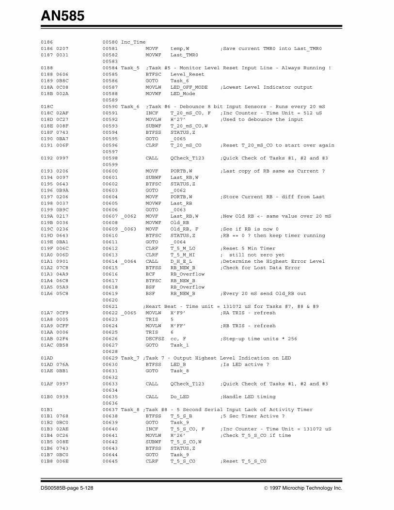
AN585
0186 00580 Inc_Time 0186 0207 00581 MOVF temp,W ;Save current TMR0 into Last_TMR00187 0031 00582 MOVWF Last_TMR0 00583 0188 00584 Task_5 ;Task #5 - Monitor Level Reset Input Line - Always Running ! 0188 0606 00585 BTFSC Level_Reset0189 0B8C 00586 GOTO Task_6018A 0C08 00587 MOVLW LED_OFF_MODE ;Lowest Level Indicator output018B 002A 00588 MOVWF LED_Mode 00589 018C 00590 Task_6 ;Task #6 - Debounce 8 bit Input Sensors - Runs every 20 mS 018C 02AF 00591 INCF T_20_mS_CO, F ;Inc Counter - Time Unit = 512 uS018D 0C27 00592 MOVLW H’27’ ;Used to debounce the input 018E 008F 00593 SUBWF T_20_mS_CO,W018F 0743 00594 BTFSS STATUS,Z0190 0BA7 00595 GOTO _00650191 006F 00596 CLRF T_20_mS_CO ;Reset T_20_mS_CO to start over again 00597 0192 0997 00598 CALL QCheck_T123 ;Quick Check of Tasks #1, #2 and #3 00599 0193 0206 00600 MOVF PORTB,W ;Last copy of RB same as Current ? 0194 0097 00601 SUBWF Last_RB,W0195 0643 00602 BTFSC STATUS,Z 0196 0B9A 00603 GOTO _00620197 0206 00604 MOVF PORTB,W ;Store Current RB - diff from Last0198 0037 00605 MOVWF Last_RB0199 0B9C 00606 GOTO _0063019A 0217 00607 _0062 MOVF Last_RB,W ;New Old RB <- same value over 20 mS 019B 0036 00608 MOVWF Old_RB019C 0236 00609 _0063 MOVF Old_RB, F ;See if RB is now 0 019D 0643 00610 BTFSC STATUS,Z ;RB == 0 ? then keep timer running 019E 0BA1 00611 GOTO _0064019F 006C 00612 CLRF T_5_M_LO ;Reset 5 Min Timer 01A0 006D 00613 CLRF T_5_M_HI ; still not zero yet 01A1 0901 00614 _0064 CALL D_H_E_L ;Determine the Highest Error Level01A2 07C8 00615 BTFSS RB_NEW_B ;Check for Lost Data Error 01A3 04A9 00616 BCF RB_Overflow01A4 06C8 00617 BTFSC RB_NEW_B01A5 05A9 00618 BSF RB_Overflow01A6 05C8 00619 BSF RB_NEW_B ;Every 20 mS send Old_RB out 00620 00621 ;Heart Beat - Time unit = 131072 uS for Tasks #7, #8 & #901A7 0CF9 00622 _0065 MOVLW H’F9’ ;RA TRIS - refresh 01A8 0005 00623 TRIS 501A9 0CFF 00624 MOVLW H’FF’ ;RB TRIS - refresh 01AA 0006 00625 TRIS 601AB 02F4 00626 DECFSZ cc, F ;Step-up time units * 256 01AC 0B58 00627 GOTO Task_1 00628 01AD 00629 Task_7 ;Task 7 - Output Highest Level Indication on LED01AD 076A 00630 BTFSS LED_B ;Is LED active ? 01AE 0BB1 00631 GOTO Task_8 00632 01AF 0997 00633 CALL QCheck_T123 ;Quick Check of Tasks #1, #2 and #3 00634 01B0 0939 00635 CALL Do_LED ;Handle LED timing 00636 01B1 00637 Task_8 ;Task #8 - 5 Second Serial Input Lack of Activity Timer01B1 0768 00638 BTFSS T_5_S_B ;5 Sec Timer Active ? 01B2 0BC0 00639 GOTO Task_901B3 02AE 00640 INCF T_5_S_CO, F ;Inc Counter - Time Unit = 131072 uS 01B4 0C26 00641 MOVLW H’26’ ;Check T_5_S_CO if time 01B5 008E 00642 SUBWF T_5_S_CO,W01B6 0743 00643 BTFSS STATUS,Z01B7 0BC0 00644 GOTO Task_901B8 006E 00645 CLRF T_5_S_CO ;Reset T_5_S_CO
DS00585B-page 5-128 1997 Microchip Technology Inc.

AN585
01B9 0C8F 00646 MOVLW LED_ON_MODE ;Highest Level Indicator output 01BA 002A 00647 MOVWF LED_Mode01BB 07E8 00648 BTFSS S_5_S_B ;Check if Lost Data Error 01BC 04C9 00649 BCF S_5_S_Overflow01BD 06E8 00650 BTFSC S_5_S_B01BE 05C9 00651 BSF S_5_S_Overflow01BF 05E8 00652 BSF S_5_S_B ;Send notice of 5 seconds of inaction 00653 01C0 00654 Task_9 ;Task #9 - 5 Min. Lack of Severe Error from Sensors Reset Timer01C0 0788 00655 BTFSS T_5_M_B ;5 Min Timer Active ? 01C1 0BD1 00656 GOTO Task_A01C2 02AC 00657 INCF T_5_M_LO, F ;Inc LO Counter; Time Unit = 131072 uS 01C3 0643 00658 BTFSC STATUS,Z ;See if carry needs to be passed on ?01C4 02AD 00659 INCF T_5_M_HI, F ;Inc HI Counter; Time Unit = 131072 uS01C5 0C08 00660 MOVLW H’08’ ;#2288< Check T_5_M_HI if time 01C6 008D 00661 SUBWF T_5_M_HI,W01C7 0743 00662 BTFSS STATUS,Z01C8 0BD1 00663 GOTO Task_A01C9 0CF0 00664 MOVLW H’F0’ ;#2288> Check T_5_M_LO if time 01CA 008C 00665 SUBWF T_5_M_LO,W01CB 0743 00666 BTFSS STATUS,Z01CC 0BD1 00667 GOTO Task_A01CD 006C 00668 CLRF T_5_M_LO ;Reset T_5_M_LO 01CE 006D 00669 CLRF T_5_M_HI ;Reset T_5_M_HI 01CF 0C08 00670 MOVLW LED_OFF_MODE ;Lowest Level Indicator output 01D0 002A 00671 MOVWF LED_Mode01D1 00672 Task_A 01D1 0B58 00673 GOTO Task_1 ;Loop Forever 00674 00675 ;****01D2 00676 Do_D_H_E_L ; Determine the Highest Error Level & Start Task #701D2 0C07 00677 MOVLW H’07’ ;Check top 7 bits 01D3 0027 00678 MOVWF temp01D4 0216 00679 MOVF Old_RB,W ;Get copy of 7 debounced Sensor Input01D5 0037 00680 MOVWF Last_RB01D6 0377 00681 _0070 RLF Last_RB, F ;Put top bit into C bit01D7 0603 00682 BTFSC STATUS,C ;Check if C bit is set 01D8 0BDE 00683 GOTO _007201D9 02E7 00684 DECFSZ temp, F ;Continue to check lesser bits01DA 0BD6 00685 GOTO _007001DB 0206 00686 _0071 MOVF PORTB,W ;Restore current value of RB 01DC 0037 00687 MOVWF Last_RB01DD 0800 00688 RETLW H’00’01DE 020A 00689 _0072 MOVF LED_Mode,W ;Get current Level Indicator 01DF 0E07 00690 ANDLW H’07’ ;Get only “ “ 01E0 0037 00691 MOVWF Last_RB ;Store into a temporary register 01E1 0207 00692 MOVF temp,W ;Check if already at this Level01E2 0097 00693 SUBWF Last_RB,W01E3 0603 00694 BTFSC STATUS,C01E4 0BDB 00695 GOTO _007101E5 0C88 00696 MOVLW H’88’ ;Start to build LED_Mode 01E6 0107 00697 IORWF temp,W ;Put new Level Indicator into reg 01E7 002A 00698 MOVWF LED_Mode ;Store new LED Mode 01E8 0BDB 00699 GOTO _0071 00700 01E9 00701 Do_Clear_Regs ; Clear Registers 7-1Fh01E9 0C1F 00702 MOVLW H’1F’ ;First regs to clear01EA 0024 00703 MOVWF FSR01EB 0060 00704 Loop_C CLRF INDIR ;Clear reg 01EC 00E4 00705 DECF FSR, F ;point to next reg to clear 01ED 0CE7 00706 MOVLW H’E7’ ;Dec temp, jump if not done01EE 0084 00707 SUBWF FSR,W01EF 0603 00708 BTFSC STATUS,C01F0 0BEB 00709 GOTO Loop_C01F1 0064 00710 CLRF FSR ;Lastly clear FSR reg 01F2 0800 00711 RETLW H’00’
1997 Microchip Technology Inc. DS00585B-page 5-129

AN585
00712 01FF 00713 ORG H’1FF’ ;RESET to Main01FF 0B43 00714 GOTO Main 00715 00716 ENDMEMORY USAGE MAP (‘X’ = Used, ‘-’ = Unused)
0000 : XXXXXXXXXXXXXXXX XXXXXXXXXXXXXXXX XXXXXXXXXXXXXXXX XXXXXXXXXXXXXXXX0040 : XXXXXXXXXXXXXXXX XXXXXXXXXXXXXXXX XXXXXXXXXXXXXXXX XXXXXXXXXXXXXXXX0080 : XXXXXXXXXXXXXXXX XXXXXXXXXXXXXXXX XXXXXXXXXXXXXXXX XXXXXXXXXXXXXXXX00C0 : XXXXXXXXXXXXXXXX XXXXXXXXXXXXXXXX XXXXXXXXXXXXXXXX XXXXXXXXXXXXXXXX0100 : XXXXXXXXXXXXXXXX XXXXXXXXXXXXXXXX XXXXXXXXXXXXXXXX XXXXXXXXXXXXXXXX0140 : XXXXXXXXXXXXXXXX XXXXXXXXXXXXXXXX XXXXXXXXXXXXXXXX XXXXXXXXXXXXXXXX0180 : XXXXXXXXXXXXXXXX XXXXXXXXXXXXXXXX XXXXXXXXXXXXXXXX XXXXXXXXXXXXXXXX01C0 : XXXXXXXXXXXXXXXX XXXXXXXXXXXXXXXX XXXXXXXXXXXXXXXX XXX------------X
All other memory blocks unused.
Program Memory Words Used: 500Program Memory Words Free: 12
Errors : 0Warnings : 0 reported, 0 suppressedMessages : 0 reported, 0 suppressed
DS00585B-page 5-130 1997 Microchip Technology Inc.

AN585
APPENDIX D:MPASM 01.40 Released APP_D.ASM 1-16-1997 17:10:05 PAGE 1
LOC OBJECT CODE LINE SOURCE TEXT VALUE
00001 list p=16C64,t=ON,c=132 00002 ; 00003 ;***************************************************************** 00004 ; 00005 ; ‘Remote Alarm64’ V1.00 00006 ; Designed by Myriad Development Co. - Jerry Farmer 00007 ; PIC16C64, 4MHz Crystal, WatchDog Timer OFF, MPASM instruction set 00008 ; PIC16C54, 4MHz Crystal, WatchDog Timer OFF 00009 ; Program: APP_D.ASM 00010 ; Revision Date: 00011 ; 1-15-97 Compatibility with MPASMWIN 1.40 00012 ; 00013 ;***************************************************************** 00014 ; 00015 00016 include “P16C64.INC” 00001 LIST 00002 ;P16C64.INC Standard Header File,Ver. 1.01 Microchip Technology, Inc. 00238 LIST 00017 00018 ; B Register Definitions 00000000 00019 Serial_IN_1 equ 0 ;Serial Input #1 - 8 bits - INT pin 00020 ;RB.7 - RB.1 == Input from Sensors 000000FF 00021 RB_TRIS equ B’11111111’ ;RB TRIS at INIT State == all input 00000000 00022 RB_MASK equ B’00000000’ ;What is High/Low for RB at INIT State 00023 00024 ; A Register Definitions - Programmable Inputs 00000000 00025 Level_Reset equ 0 ;PORTA.0 - Reset Level Indicator 00000001 00026 LED equ 1 ;LED Output - Level/State Indicator 00000002 00027 Serial_Out equ 2 ;Serial Output - 8 bits + passwords 00000003 00028 PWM_Out equ 3 ;PWM Output - 8 bits ON, 8 bits OFF 00029 000000F1 00030 RA_TRIS equ B’11110001’ ;RA TRIS at INIT State 00000000 00031 RA_MASK equ B’00000000’ ;What is High/Low for RA at INIT State 00032 00033 ; Register Files 00000020 00034 temp equ 20h ;Temporary holding register - PIC16C54/56 00000021 00035 tmp equ 21h ;Temporary reg 00000022 00036 Temp_W equ 22h ;Interrupt storage of W 00000023 00037 Temp_Stat equ 23h ;Interrupt storage of STATUS 00000024 00038 Temp_FSR equ 24h ;Interrupt storage of FSR 00000025 00039 T_B equ 25h ;Indicates which Timer(s) are Active = 1 00000026 00040 FLAGS equ 26h ;Error Flags 00000027 00041 LED_Mode equ 27h ;(0-2)=Mode, 3=LED_B, (4-6)=Seq #, 7=NEW 00000028 00042 OState equ 28h ;Serial Out State 00000029 00043 IState1 equ 29h ;Serial In #1 State 0000002A 00044 cc equ 2Ah ;256 * TMR0 time 0000002B 00045 T_5_M_LO equ 2Bh ;5 Min Timer Counter - Low 0000002C 00046 T_5_M_HI equ 2Ch ;5 Min Timer Counter - High 0000002D 00047 T_5_S_CO equ 2Dh ;5 Second Timer - lack of Serial Input 0000002E 00048 T_20_mS_CO equ 2Eh ;20 mS Timer - used for debouncing 0000002F 00049 T_PWM_CO equ 2Fh ;PWM Counter 00000030 00050 LED_C equ 30h ;LED Counter 00000031 00051 xmt_byte equ 31h ;Serial xmit byte - destroyed in use
Please check the Microchip BBS for the latest version of the source code. Microchip’s Worldwide Web Address: www.microchip.com; Bulletin Board Support: MCHIPBBS using CompuServe® (CompuServe membership not required).
1997 Microchip Technology Inc. DS00585B-page 5-131

AN585
00000032 00052 rcv_byte_1 equ 32h ;Receive Serial #1 In byte 00000033 00053 RCV_Storage equ 33h ;Long term storage of rcv_byte #1 00000034 00054 Old_RB equ 34h ;Oldest/Master copy of RB 00000035 00055 Last_RB equ 35h ;Last copy of RB 00000036 00056 PWM_ON equ 36h ;PWM ON Counter 00000037 00057 PWM_OFF equ 37h ;PWM OFF Counter 00000038 00058 PWM_tmp equ 38h ;PWM temporary counter 00059 00060 ; Indicates which Timer(s) are Active = 1 & Flags - T_B 00000000 00061 OState_B equ 0 ;Serial Out Active Bit 00000001 00062 IState1_B equ 1 ;Serial IN #1 Active Bit 00000002 00063 T_5_S_B equ 2 ;5 Second Timer Active Bit 00000003 00064 T_5_M_B equ 3 ;5 Min Timer Active Bit 00000004 00065 RCV_Got_One_B equ 4 ;Got a NEW Received byte to send out 00000005 00066 RB_NEW_B equ 5 ;Indicates a change in RB input 00000006 00067 S_5_S_B equ 6 ;Serial In 5 secs of inactivity 00000007 00068 T_PWM_B equ 7 ;PWM Activity Bit 00069 00070 ; Error Flags - FLAGS 00000000 00071 FS_Flag_1 equ 0 ;Serial #1 IN had a False Start Error 00000001 00072 FE_Flag_1 equ 1 ;Last Serial #1 IN had a Frame Error 00000002 00073 RCV_Overflow equ 2 ;Lost Serial Input Byte - too Slow 00000003 00074 RB_Overflow equ 3 ;Lost RB Input Byte - too Slow 00000004 00075 S_5_S_Overflow equ 4 ;Lost ‘5S Inactivity’ msg - too Slow 00000005 00076 Time_Bit equ 5 ;Indicate 512 uS has passed 00077 00078 ;Equates for LED Task #7 - LED_Mode 00000003 00079 LED_B equ 3 ;LED is active - LED_Mode.3 00000007 00080 LED_NEW_B equ 7 ;LED has just changed Modes = 1 00000008 00081 LED_OFF_MODE equ B’00001000’ ;LED OFF 00000089 00082 LED_SEQ1_MODE equ B’10001001’ ;LED Sequence 1: .2s On, 1s Off 0000008A 00083 LED_SEQ2_MODE equ B’10001010’ ;LED Sequence 2: 3x(.2s), 1s Off 0000008B 00084 LED_SEQ3_MODE equ B’10001011’ ;LED Sequence 3: 5x(.2s), 1s Off 0000009C 00085 LED_SLOW_MODE equ B’10011100’ ;LED Slow Pulsing - .3 Hz 0000009D 00086 LED_MEDIUM_MODE equ B’10011101’ ;LED Medium Pulsing - 1 Hz 0000009E 00087 LED_FAST_MODE equ B’10011110’ ;LED Fast Pulsing - 3 Hz 0000008F 00088 LED_ON_MODE equ B’10001111’ ;LED ON Continuously 00089 0000 00090 ORG 0 ;Reset Vector 00091 0000 28F7 00092 GOTO Main 00093 0004 00094 ORG 4 ;Interrupt Vector 00095 0004 29D4 00096 GOTO Interrupt 00097 00098 ;****** Task #1 - Asynchronous 9600 Baud Serial Output (LOW=0)0005 00099 Do_OState 0005 0828 00100 MOVF OState,W ;Get (0-A) mode #0006 390F 00101 ANDLW H’0F’ ;Get only mode # 0007 0782 00102 ADDWF PCL, F ;jump to subroutine0008 2814 00103 GOTO OStateS ;Serial Start Bit0009 2823 00104 GOTO OState0_7 ;Bit 0 000A 2823 00105 GOTO OState0_7 ;Bit 1 000B 2823 00106 GOTO OState0_7 ;Bit 2 000C 2823 00107 GOTO OState0_7 ;Bit 3 000D 2823 00108 GOTO OState0_7 ;Bit 4 000E 2823 00109 GOTO OState0_7 ;Bit 5 000F 2823 00110 GOTO OState0_7 ;Bit 6 0010 2823 00111 GOTO OState0_7 ;Bit 7 0011 2829 00112 GOTO OStateE ;Serial Stop Bit0012 2831 00113 GOTO OStateL ;Last State 0013 0008 00114 RETURN 00115 0014 00116 OStateS 0014 3000 00117 MOVLW H’00’ ;Post & Pre 1=1 & OFF
DS00585B-page 5-132 1997 Microchip Technology Inc.

AN585
0015 0092 00118 MOVWF T2CON0016 1683 00119 BSF STATUS,RP0 ;Point to BANK 10017 3053 00120 MOVLW H’68’ - H’15’ ;104uS - 9600 Baud & adjust to Latency Message[302]: Register in operand not in bank 0. Ensure that bank bits are correct.0018 0092 00121 MOVWF PR20019 1283 00122 BCF STATUS,RP0 ;Point to BANK 0001A 0191 00123 CLRF TMR2 ;Init to 0001B 108C 00124 BCF PIR1,TMR2IF ;Clear Timer 2 Flag so as to start fresh001C 1505 00125 BSF PORTA,Serial_Out;Output ‘Serial Start Bit’ starting Now001D 1512 00126 BSF T2CON,TMR2ON ;Start Timer 2001E 0AA8 00127 INCF OState, F ;inc to next state BEFORE allowing interrupt 00128 001F 1683 00129 BSF STATUS,RP0 ;Point to BANK 1Message[302]: Register in operand not in bank 0. Ensure that bank bits are correct.0020 148C 00130 BSF PIE1,TMR2IE ;Allow for Timer 2 interrupts0021 1283 00131 BCF STATUS,RP0 ;Point to BANK 00022 0008 00132 RETURN 00133 0023 00134 OState0_7 ;Bit 0 - 7 0023 0CB1 00135 RRF xmt_byte, F ;Move bit into C from right most bit0024 1C03 00136 BTFSS STATUS,C ;Output C bit 0025 1105 00137 BCF PORTA,Serial_Out ;0026 1803 00138 BTFSC STATUS,C ;0027 1505 00139 BSF PORTA,Serial_Out ;0028 282A 00140 GOTO OS_End0029 00141 OStateE 0029 1105 00142 BCF PORTA,Serial_Out ;Serial Stop Bit 002A 108C 00143 OS_End BCF PIR1,TMR2IF ;Clear Timer 2 Flag so as to start fresh002B 1683 00144 BSF STATUS,RP0 ;Point to BANK 1002C 306C 00145 MOVLW H’68’ + H’4 ;104uS - 9600 Baud & adjust to LatencyMessage[302]: Register in operand not in bank 0. Ensure that bank bits are correct.002D 0092 00146 MOVWF PR2002E 1283 00147 BCF STATUS,RP0 ;Point to BANK 0002F 0AA8 00148 INCF OState, F ;increment to next state 0030 0008 00149 RETURN0031 00150 OStateL 0031 1683 00151 BSF STATUS,RP0 ;Point to BANK 1Message[302]: Register in operand not in bank 0. Ensure that bank bits are correct.0032 108C 00152 BCF PIE1,TMR2IE ;Do NOT Allow Timer 2 interrupts0033 1283 00153 BCF STATUS,RP0 ;Point to BANK 0 00154 0034 108C 00155 BCF PIR1,TMR2IF ;Clear Timer 2 Flag so as to start fresh0035 1112 00156 BCF T2CON,TMR2ON ;Stop Timer 20036 01A8 00157 CLRF OState ;Ready to send next byte out 0037 1025 00158 BCF T_B,OState_B ;Serial Out not active 0038 0008 00159 RETURN 00160 00161 ;****** Task #7 - Output Highest Level Indication on LED 0039 00162 Do_LED 0039 1BA7 00163 BTFSC LED_Mode,LED_NEW_B;Initialize regs if change in modes 003A 284C 00164 GOTO LED_NEW003B 0AB0 00165 INCF LED_C, F ;Inc Counter - Time Unit = 131072 uS 003C 0827 00166 MOVF LED_Mode,W ;Get (0-7) mode # 003D 3907 00167 ANDLW H’07’ ;Get only mode #003E 0782 00168 ADDWF PCL, F ;jump to subroutine 003F 2848 00169 GOTO LED_OFF ;LED OFF 0040 2864 00170 GOTO LED_SEQ1 ;LED Seq 1: 1 short pulse & pause 0041 2867 00171 GOTO LED_SEQ2 ;LED Seq 2: 2 short pulses & pause0042 288A 00172 GOTO LED_SEQ3 ;LED Seq 3: 3 short pulses & pause 0043 2850 00173 GOTO LED_SLOW ;LED Slow Pulsing - .3 Hz 0044 285E 00174 GOTO LED_MEDIUM ;LED Medium Pulsing - 1 Hz0045 2861 00175 GOTO LED_FAST ;LED Fast Pulsing - 3 Hz 0046 284D 00176 GOTO LED_ON ;LED ON Continuously 0047 0008 00177 _0012 RETURN 00178 ;------0048 00179 LED_OFF
1997 Microchip Technology Inc. DS00585B-page 5-133

AN585
0048 1085 00180 BCF PORTA,LED ;Turn off LED 0049 11A7 00181 BCF LED_Mode,LED_B ;LED must be off 004A 01B0 00182 CLRF LED_C ;Reset Counter - LED_C = 0 004B 0008 00183 RETURN 00184 ;------004C 00185 LED_NEW 004C 13A7 00186 BCF LED_Mode,LED_NEW_B ;Done initializing004D 00187 LED_ON 004D 1485 00188 BSF PORTA,LED ;Turn on LED004E 01B0 00189 CLRF LED_C ;Reset Counter - LED_C = 0 004F 0008 00190 RETURN 00191 ;------0050 00192 LED_SLOW 0050 300C 00193 MOVLW H’0C’ ;.3Hz @ 50% Duty 0051 00A0 00194 MOVWF temp0052 0820 00195 LED_S MOVF temp,W ;Check LED_C if time, .3Hz @ 50% Duty 0053 0230 00196 SUBWF LED_C,W0054 1D03 00197 BTFSS STATUS,Z0055 2847 00198 GOTO _00120056 3010 00199 MOVLW H’10’0057 06A7 00200 XORWF LED_Mode, F ;Switch states 0058 1E27 00201 BTFSS LED_Mode,4 ;Now make LED same state0059 1085 00202 BCF PORTA,LED005A 1A27 00203 BTFSC LED_Mode,4005B 1485 00204 BSF PORTA,LED005C 01B0 00205 CLRF LED_C ;Reset LED_C005D 0008 00206 RETURN 00207 ;------005E 00208 LED_MEDIUM 005E 3004 00209 MOVLW H’04’ ;1Hz @ 50% Duty 005F 00A0 00210 MOVWF temp 0060 2852 00211 GOTO LED_S ;Go do it 00212 ;------0061 00213 LED_FAST 0061 3001 00214 MOVLW H’01’ ;3Hz @ 50% Duty 0062 00A0 00215 MOVWF temp0063 2852 00216 GOTO LED_S ;Go do it 00217 ;------0064 00218 LED_SEQ1 ;.2 ON, 1 OFF 0064 1E27 00219 BTFSS LED_Mode,4 ;Skip if bit is high 0065 2876 00220 GOTO ON1 ;Go do it 0066 2882 00221 GOTO OFF3 ;Go do it 00222 ;------0067 00223 LED_SEQ2 ;.2 ON, .2 OFF, .2 ON, 1 OFF 0067 0827 00224 MOVF LED_Mode,W0068 00A0 00225 MOVWF temp0069 3030 00226 MOVLW H’30’ ;Get sequence # only 006A 05A0 00227 ANDWF temp, F006B 0EA0 00228 SWAPF temp, F ;swap nibbles 006C 0820 00229 MOVF temp,W ;get nibble for offset 006D 0782 00230 ADDWF PCL, F ;Table jump calculation 006E 2876 00231 GOTO ON1 ;LED is on, check if time to change 006F 287C 00232 GOTO OFF2 ;LED is off, check if time to change0070 2876 00233 GOTO ON1 ;LED is on, check if time to change 0071 2882 00234 GOTO OFF3 ;LED is off, check if time to change 00235 ;------0072 00236 LED_Exit 0072 3010 00237 MOVLW H’10’ ;Inc Seq # 0073 07A7 00238 ADDWF LED_Mode, F0074 01B0 00239 CLRF LED_C ;Reset LED_C 0075 0008 00240 RETURN0076 00241 ON1 0076 3002 00242 MOVLW H’02’ ;Check LED_C if time, .2 sec-on 0077 0230 00243 SUBWF LED_C,W0078 1D03 00244 BTFSS STATUS,Z0079 2847 00245 GOTO _0012
DS00585B-page 5-134 1997 Microchip Technology Inc.

AN585
007A 1085 00246 BCF PORTA,LED ;Turn off LED 007B 2872 00247 GOTO LED_Exit007C 00248 OFF2 007C 3002 00249 MOVLW H’02’ ;Check LED_C if time, .2 sec-on007D 0230 00250 SUBWF LED_C,W007E 1D03 00251 BTFSS STATUS,Z007F 2847 00252 GOTO _00120080 1485 00253 BSF PORTA,LED ;Turn on LED 0081 2872 00254 GOTO LED_Exit0082 00255 OFF3 0082 3008 00256 MOVLW H’08’ ;Check LED_C if time, 1 sec-off 0083 0230 00257 SUBWF LED_C,W0084 1D03 00258 BTFSS STATUS,Z0085 2847 00259 GOTO _00120086 1485 00260 BSF PORTA,LED ;Turn on LED 0087 30F0 00261 MOVLW H’F0’0088 04A7 00262 IORWF LED_Mode, F ;Cause (Seq# & NEW) to overflow to 00089 2872 00263 GOTO LED_Exit008A 00264 LED_SEQ3 ;.2 ON, .2 OFF, .2 ON, .2 OFF, .2 ON, 1 OFF 008A 0827 00265 MOVF LED_Mode,W ;Get LED info 008B 00A0 00266 MOVWF temp008C 3070 00267 MOVLW H’70’ ;Get sequence # only 008D 05A0 00268 ANDWF temp, F 008E 0EA0 00269 SWAPF temp, F ;swap nibbles008F 0820 00270 MOVF temp,W ;get nibble for offset 0090 0782 00271 ADDWF PCL, F ;Table jump calculation 0091 2876 00272 GOTO ON1 ;LED is on check if time to change 0092 287C 00273 GOTO OFF2 ;LED is off check if time to change 0093 2876 00274 GOTO ON1 ;LED is on check if time to change0094 287C 00275 GOTO OFF2 ;LED is off check if time to change 0095 2876 00276 GOTO ON1 ;LED is on check if time to change0096 2882 00277 GOTO OFF3 ;LED is off check if time to change 00278 00279 ;****** Task #2 - Asynchronous 4800 Baud Serial Input (LOW=0)0097 00280 Do_I1State 0097 0829 00281 MOVF IState1,W ;Get (0-B) mode #0098 390F 00282 ANDLW H’0F’ ;Get only mode # 0099 0782 00283 ADDWF PCL, F ;jump to subroutine009A 28A7 00284 GOTO I1StateS ;Serial Start Bit 009B 28B8 00285 GOTO I1State2 ;1/2 of Start Bit - see if False Start009C 28C5 00286 GOTO I1State0_7 ;Bit 0 009D 28C5 00287 GOTO I1State0_7 ;Bit 1 009E 28C5 00288 GOTO I1State0_7 ;Bit 2 009F 28C5 00289 GOTO I1State0_7 ;Bit 3 00A0 28C5 00290 GOTO I1State0_7 ;Bit 4 00A1 28C5 00291 GOTO I1State0_7 ;Bit 5 00A2 28C5 00292 GOTO I1State0_7 ;Bit 6 00A3 28C5 00293 GOTO I1State0_7 ;Bit 7 00A4 28D4 00294 GOTO I1StateE ;Serial Stop Bit 00A5 28DF 00295 GOTO I1StateL ;Last State - End of Stop Bit00A6 0008 00296 RETURN 00297 00298 ;*** Subroutines for Task #200A7 00299 I1StateS ;Start Bit - Setup timing variables00A7 120B 00300 BCF INTCON,INTE ;Disable detecting changes on INT pin00A8 108B 00301 BCF INTCON,INTF ;Clear Interrupting Flag00A9 3000 00302 MOVLW H’00’ ;Internal Clk, Pre 1=1 & OFF00AA 0090 00303 MOVWF T1CON00AB 018E 00304 CLRF TMR1L ;Calculate (0 - #) of counts until roll-over00AC 304A 00305 MOVLW H’68’ - H’1E’ ;208us/2 = 4800 Baud & adjust to Latency00AD 028E 00306 SUBWF TMR1L, F00AE 018F 00307 CLRF TMR1H00AF 038F 00308 DECF TMR1H, F ;H’FF’00B0 100C 00309 BCF PIR1,TMR1IF ;Clear Timer 1 Flag so as to start fresh00B1 1410 00310 BSF T1CON,TMR1ON ;Start Timer 100B2 0AA9 00311 INCF IState1, F ;inc to next state BEFORE allowing interrupts
1997 Microchip Technology Inc. DS00585B-page 5-135

AN585
00B3 14A5 00312 BSF T_B,IState1_B ;Serial Input Active 00313 00B4 1683 00314 BSF STATUS,RP0 ;Point to BANK 1Message[302]: Register in operand not in bank 0. Ensure that bank bits are correct.00B5 140C 00315 BSF PIE1,TMR1IE ;Allow for Timer 1 interrupts00B6 1283 00316 BCF STATUS,RP0 ;Point to BANK 000B7 0008 00317 RETURN00B8 00318 I1State2 ;Check if still a Start Bit00B8 1C06 00319 BTFSS PORTB,Serial_IN_1 ;False Start Error ? 00B9 28E9 00320 GOTO FS_Error_100BA 1026 00321 BCF FLAGS,FS_Flag_1 ;Start Bit OK 00BB 1010 00322 BCF T1CON,TMR1ON ;Stop Timer 100BC 018E 00323 CLRF TMR1L00BD 30AA 00324 MOVLW H’D0’ - H’26’ ;208us = 4800 Baud & adjust to Latency00BE 028E 00325 SUBWF TMR1L, F00BF 018F 00326 CLRF TMR1H00C0 038F 00327 DECF TMR1H, F ;H’FF’00C1 100C 00328 BCF PIR1,TMR1IF ;Clear Timer 1 Flag so as to start fresh00C2 1410 00329 BSF T1CON,TMR1ON ;Start Timer 100C3 0AA9 00330 INCF IState1, F ;increment to next state00C4 0008 00331 RETURN00C5 00332 I1State0_7 ;Bit 0 - 7 00C5 1C06 00333 BTFSS PORTB,Serial_IN_1 ;Move Input bit into C 00C6 1003 00334 BCF STATUS,C00C7 1806 00335 BTFSC PORTB,Serial_IN_100C8 1403 00336 BSF STATUS,C00C9 0CB2 00337 RRF rcv_byte_1, F ;Move C into left most bit 00CA 1010 00338 BCF T1CON,TMR1ON ;Stop Timer 100CB 018E 00339 CLRF TMR1L00CC 30AA 00340 MOVLW H’D0’ - H’26’ ;208us = 4800 Baud & adjust to Latency00CD 028E 00341 SUBWF TMR1L, F00CE 018F 00342 CLRF TMR1H00CF 038F 00343 DECF TMR1H, F ;H’FF’00D0 100C 00344 BCF PIR1,TMR1IF ;Clear Timer 1 Flag so as to start fresh00D1 1410 00345 BSF T1CON,TMR1ON ;Start Timer 100D2 0AA9 00346 INCF IState1, F ;increment to next state 00D3 0008 00347 RETURN00D4 00348 I1StateE ;Check if we have a proper Stop Bit00D4 1806 00349 BTFSC PORTB,Serial_IN_1 ;Frame Error00D5 28EC 00350 GOTO F_Error_100D6 10A6 00351 BCF FLAGS,FE_Flag_1 ;Stop Bit OK00D7 01AD 00352 CLRF T_5_S_CO ;Reset 5 Sec Timer - got a good byte 00353 ;Process the msg Here !00D8 0832 00354 MOVF rcv_byte_1,W ;Make a copy of just received byte 00D9 00B3 00355 MOVWF RCV_Storage00DA 1E25 00356 BTFSS T_B,RCV_Got_One_B ;Report Lost data 00DB 1126 00357 BCF FLAGS,RCV_Overflow00DC 1A25 00358 BTFSC T_B,RCV_Got_One_B00DD 1526 00359 BSF FLAGS,RCV_Overflow00DE 1625 00360 BSF T_B,RCV_Got_One_B ;We Now have a RB Value to go out 00DF 00361 I1StateL 00DF 1010 00362 BCF T1CON,TMR1ON ;Stop Timer 100E0 1683 00363 BSF STATUS,RP0 ;Point to BANK 1Message[302]: Register in operand not in bank 0. Ensure that bank bits are correct.00E1 140C 00364 BSF PIE1,TMR1IE ;Allow for Timer 1 interrupts00E2 1283 00365 BCF STATUS,RP0 ;Point to BANK 000E3 100C 00366 BCF PIR1,TMR1IF ;Clear Timer 1 Flag so as to start fresh 00367 00E4 01A9 00368 CLRF IState1 ;Ready to receive next byte00E5 10A5 00369 BCF T_B,IState1_B ;Serial In not currently active 00370 00E6 108B 00371 BCF INTCON,INTF ;Clear Interrupting Flag00E7 160B 00372 BSF INTCON,INTE ;Enable detecting changes on INT pin00E8 0008 00373 RETURN00E9 00374 FS_Error_1 ;False Start - Shut Down Checking00E9 10A5 00375 BCF T_B,IState1_B ;Serial Input NOT Active
DS00585B-page 5-136 1997 Microchip Technology Inc.
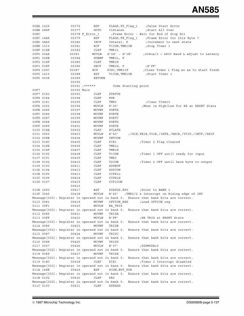
AN585
00EA 1426 00376 BSF FLAGS,FS_Flag_1 ;False Start Error 00EB 28DF 00377 GOTO I1StateL ;Start All Over 00EC 00378 F_Error_1 ;Frame Error - Wait for End of Stop Bit 00EC 14A6 00379 BSF FLAGS,FE_Flag_1 ;Frame Error for this Byte ?00ED 0AA9 00380 INCF IState1, F ;Increment to next state00EE 1010 00381 BCF T1CON,TMR1ON ;Stop Timer 100EF 018E 00382 CLRF TMR1L00F0 304A 00383 MOVLW H’68’ - H’1E’ ;208us/2 = 4800 Baud & adjust to Latency00F1 028E 00384 SUBWF TMR1L, F00F2 018F 00385 CLRF TMR1H00F3 038F 00386 DECF TMR1H, F ;H’FF’00F4 100C 00387 BCF PIR1,TMR1IF ;Clear Timer 1 Flag so as to start fresh00F5 1410 00388 BSF T1CON,TMR1ON ;Start Timer 100F6 0008 00389 RETURN 00390 00391 ;****** Code Starting point00F7 00392 Main 00F7 0183 00393 CLRF STATUS00F8 0184 00394 CLRF FSR00F9 0181 00395 CLRF TMR0 ;Clear Timer000FA 3000 00396 MOVLW H’00’ ;What is High/Low for RA at RESET State 00FB 0085 00397 MOVWF PORTA00FC 0086 00398 MOVWF PORTB00FD 0087 00399 MOVWF PORTC00FE 0088 00400 MOVWF PORTD00FF 0089 00401 MOVWF PORTE0100 018A 00402 CLRF PCLATH0101 3060 00403 MOVLW H’60’ ;/GIE,PEIE,T0IE,/INTE,/RBIE,/T0IF,/INTF,/RBIF0102 008B 00404 MOVWF INTCON0103 018C 00405 CLRF PIR1 ;Timer 2 Flag cleared0104 018E 00406 CLRF TMR1L0105 018F 00407 CLRF TMR1H0106 0190 00408 CLRF T1CON ;Timer 1 OFF until ready for input 0107 0191 00409 CLRF TMR20108 0192 00410 CLRF T2CON ;Timer 2 OFF until have byte to output0109 0193 00411 CLRF SSPBUF010A 0194 00412 CLRF SSPCON010B 0195 00413 CLRF CCPR1L010C 0196 00414 CLRF CCPR1H010D 0197 00415 CLRF CCP1CON 00416 010E 1683 00417 BSF STATUS,RP0 ;Point to BANK 1010F 3040 00418 MOVLW H’40’ ;TMR0/2 & Interrupt on Rising edge of INT Message[302]: Register in operand not in bank 0. Ensure that bank bits are correct.0110 0081 00419 MOVWF OPTION_REG ;Load OPTION reg0111 30F1 00420 MOVLW RA_TRISMessage[302]: Register in operand not in bank 0. Ensure that bank bits are correct.0112 0085 00421 MOVWF TRISA0113 30FF 00422 MOVLW H’FF’ ;RB TRIS at RESET State Message[302]: Register in operand not in bank 0. Ensure that bank bits are correct.0114 0086 00423 MOVWF TRISBMessage[302]: Register in operand not in bank 0. Ensure that bank bits are correct.0115 0087 00424 MOVWF TRISCMessage[302]: Register in operand not in bank 0. Ensure that bank bits are correct.0116 0088 00425 MOVWF TRISD0117 3007 00426 MOVLW H’07’ ;PSPMODE=0Message[302]: Register in operand not in bank 0. Ensure that bank bits are correct.0118 0089 00427 MOVWF TRISEMessage[302]: Register in operand not in bank 0. Ensure that bank bits are correct.0119 018C 00428 CLRF PIE1 ;Timer 2 Interrupt disabledMessage[302]: Register in operand not in bank 0. Ensure that bank bits are correct.011A 148E 00429 BSF PCON,NOT_POR Message[302]: Register in operand not in bank 0. Ensure that bank bits are correct.011B 0192 00430 CLRF PR2Message[302]: Register in operand not in bank 0. Ensure that bank bits are correct.011C 0193 00431 CLRF SSPADD
1997 Microchip Technology Inc. DS00585B-page 5-137

AN585
Message[302]: Register in operand not in bank 0. Ensure that bank bits are correct.011D 0194 00432 CLRF SSPSTAT 00433 011E 1283 00434 BCF STATUS,RP0 ;Point to BANK 0011F 21BF 00435 CALL Clear_Regs ;Clear Registers 20-7F, A0-C0 Memory Pages 00436 00437 ;Initialize Tasks 00438 ;Task #1 waits for byte to output 00439 ;Task #2 waits for Serial IN Start Bit0120 3031 00440 MOVLW H’31’ ;Task #3 is initialized for square pulses0121 00B6 00441 MOVWF PWM_ON ; “ 25 mS ON0122 3031 00442 MOVLW H’31’ ; “ Period = 50 mS, DS= 50%0123 00B7 00443 MOVWF PWM_OFF ; “ 25 mS OFF0124 01AF 00444 CLRF T_PWM_CO ; “0125 0836 00445 MOVF PWM_ON,W ;move PWM_tmp,PWM_ON0126 00B8 00446 MOVWF PWM_tmp ; “0127 1585 00447 BSF PORTA,PWM_Out ;Start Outputting ON0128 17A5 00448 BSF T_B,T_PWM_B ; “ 00449 ;Task #4 runs when Task 1 is Not 00450 ;Task #5 is always running0129 0806 00451 MOVF PORTB,W ;Task #6 is Initialized here 012A 00B4 00452 MOVWF Old_RB012B 0834 00453 MOVF Old_RB,W ;Make all the same initial value 012C 00B5 00454 MOVWF Last_RB012D 16A5 00455 BSF T_B,RB_NEW_B ;Tell Task #4: RB byte ready to output012E 3008 00456 MOVLW LED_OFF_MODE012F 00A7 00457 MOVWF LED_Mode ;Task #7 is Started 0130 1525 00458 BSF T_B,T_5_S_B ;Task #8 is Started here 0131 15A5 00459 BSF T_B,T_5_M_B ;Task #9 is Started here 00460 0132 178B 00461 BSF INTCON,GIE ;Enable Global Interrupts 00462 00463 ; Handle Task & Timer activities - Main Loop done in background0133 00464 Inc_Time ;Heart Beat - Time unit = 512 uS for Tasks #5 & #6 0133 1EA6 00465 BTFSS FLAGS,Time_Bit ;Idle Task - wait until 512 uS has gone by0134 2933 00466 GOTO Inc_Time0135 12A6 00467 BCF FLAGS,Time_Bit ;Reset for next indicator 00468 ;from TMR0 Interrupt0136 00469 Task_3 ;Task #3 - PWM, Period = (PWM_ON + PWM_OFF) * 512uS0136 1FA5 00470 BTFSS T_B,T_PWM_B ;if NOT outputting now then skip call0137 2947 00471 GOTO Task_40138 0AAF 00472 INCF T_PWM_CO, F ;Inc count of time0139 0838 00473 MOVF PWM_tmp,W ;cjne T_PWM_CO,PWM_tmp,Task_4013A 022F 00474 SUBWF T_PWM_CO,W ; “013B 1D03 00475 BTFSS STATUS,Z ; “013C 2947 00476 GOTO Task_4 ; “013D 01AF 00477 CLRF T_PWM_CO ;Reset timer013E 1985 00478 BTFSC PORTA,PWM_Out013F 2944 00479 GOTO T3_10140 1585 00480 BSF PORTA,PWM_Out ;Change Output State0141 0836 00481 MOVF PWM_ON,W ;move PWM_tmp,PWM_ON0142 00B8 00482 MOVWF PWM_tmp ; “0143 2947 00483 GOTO Task_40144 00484 T3_10144 1185 00485 BCF PORTA,PWM_Out ;Change Output State0145 0837 00486 MOVF PWM_OFF,W ;mov PWM_tmp,PWM_OFF0146 00B8 00487 MOVWF PWM_tmp ; “ 00488 0147 00489 Task_4 ;Task #4 - Finds next Buffered Byte to Send Out through Task 10147 1825 00490 BTFSC T_B,OState_B ;if outputting now then skip call0148 295E 00491 GOTO Task_50149 1E25 00492 BTFSS T_B,RCV_Got_One_B ;Got a NEW Received byte to send014A 2950 00493 GOTO _0057014B 0833 00494 MOVF RCV_Storage,W ;Send just received byte 014C 00B1 00495 MOVWF xmt_byte014D 1225 00496 BCF T_B,RCV_Got_One_B ;Clear need to send old byte
DS00585B-page 5-138 1997 Microchip Technology Inc.

AN585
014E 1425 00497 BSF T_B,OState_B ;Start Task #1 & Lock Out Others 014F 295D 00498 GOTO T4_S0150 1EA5 00499 _0057 BTFSS T_B,RB_NEW_B ;Indicates a change in RB input 0151 2957 00500 GOTO _00580152 0834 00501 MOVF Old_RB,W ;Send New RB value 0153 00B1 00502 MOVWF xmt_byte0154 12A5 00503 BCF T_B,RB_NEW_B ;Clear need to send out newest value 0155 1425 00504 BSF T_B,OState_B ;Start Task #1 & Lock Out Others0156 295D 00505 GOTO T4_S0157 1F25 00506 _0058 BTFSS T_B,S_5_S_B ;Serial In 5 secs of inactivity0158 295E 00507 GOTO Task_50159 30FF 00508 MOVLW H’FF’ ;Tell of inactivity of Serial In 015A 00B1 00509 MOVWF xmt_byte015B 1325 00510 BCF T_B,S_5_S_B ;Clear need to send msg 015C 1425 00511 BSF T_B,OState_B ;Start Task #1 & Lock Out Others015D 00512 T4_S ;Start Task #1015D 2005 00513 CALL Do_OState 00514 015E 00515 Task_5 ;Task #5 - Monitor Level Reset Input Line - Always Running ! 015E 1805 00516 BTFSC PORTA,Level_Reset015F 2962 00517 GOTO Task_60160 3008 00518 MOVLW LED_OFF_MODE ;Lowest Level Indicator output0161 00A7 00519 MOVWF LED_Mode 00520 0162 00521 Task_6 ;Task #6 - Debounce 8 bit Input Sensors - Runs every 20 mS 0162 0AAE 00522 INCF T_20_mS_CO, F ;Inc Counter - Time Unit = 512 uS0163 3027 00523 MOVLW H’27’ ;Used to debounce the input 0164 022E 00524 SUBWF T_20_mS_CO,W0165 1D03 00525 BTFSS STATUS,Z0166 297C 00526 GOTO _00650167 01AE 00527 CLRF T_20_mS_CO ;Reset T_20_mS_CO to start over again0168 0806 00528 MOVF PORTB,W ;Last copy of RB same as Current ? 0169 0235 00529 SUBWF Last_RB,W016A 1903 00530 BTFSC STATUS,Z 016B 296F 00531 GOTO _0062016C 0806 00532 MOVF PORTB,W ;Store Current RB - diff from Last016D 00B5 00533 MOVWF Last_RB016E 2971 00534 GOTO _0063016F 0835 00535 _0062 MOVF Last_RB,W ;New Old RB <- same value over 20 mS 0170 00B4 00536 MOVWF Old_RB0171 08B4 00537 _0063 MOVF Old_RB, F ;See if RB is now 0 0172 1903 00538 BTFSC STATUS,Z ;RB == 0 ? then keep timer running 0173 2976 00539 GOTO _00640174 01AB 00540 CLRF T_5_M_LO ;Reset 5 Min Timer 0175 01AC 00541 CLRF T_5_M_HI ; still not zero yet 0176 21A8 00542 _0064 CALL D_H_E_L ;Determine the Highest Error Level0177 1EA5 00543 BTFSS T_B,RB_NEW_B ;Check for Lost Data Error 0178 11A6 00544 BCF FLAGS,RB_Overflow0179 1AA5 00545 BTFSC T_B,RB_NEW_B017A 15A6 00546 BSF FLAGS,RB_Overflow017B 16A5 00547 BSF T_B,RB_NEW_B ;Every 20 mS send Old_RB out 00548 00549 ;Heart Beat - Time unit = 131072 uS for Tasks #7, #8 & #9017C 00550 _0065 017C 1683 00551 BSF STATUS,RP0 ;Point to BANK 1017D 30F1 00552 MOVLW RA_TRIS ;RA TRIS - refresh Message[302]: Register in operand not in bank 0. Ensure that bank bits are correct.017E 0085 00553 MOVWF TRISA017F 30FF 00554 MOVLW H’FF’ ;RB TRIS - refresh Message[302]: Register in operand not in bank 0. Ensure that bank bits are correct.0180 0086 00555 MOVWF TRISB0181 1283 00556 BCF STATUS,RP0 ;Point to BANK 00182 0BAA 00557 DECFSZ cc, F ;Step-up time units * 256 0183 2933 00558 GOTO Inc_Time 00559 0184 00560 Task_7 ;Task 7 - Output Highest Level Indication on LED
1997 Microchip Technology Inc. DS00585B-page 5-139
AN585
0184 1DA7 00561 BTFSS LED_Mode,LED_B ;Is LED active ? 0185 2987 00562 GOTO Task_80186 2039 00563 CALL Do_LED ;Handle LED timing 00564 0187 00565 Task_8 ;Task #8 - 5 Second Serial Input Lack of Activity Timer0187 1D25 00566 BTFSS T_B,T_5_S_B ;5 Sec Timer Active ? 0188 2996 00567 GOTO Task_90189 0AAD 00568 INCF T_5_S_CO, F ;Inc Counter - Time Unit = 131072 uS 018A 3026 00569 MOVLW H’26’ ;Check T_5_S_CO if time 018B 022D 00570 SUBWF T_5_S_CO,W018C 1D03 00571 BTFSS STATUS,Z018D 2996 00572 GOTO Task_9018E 01AD 00573 CLRF T_5_S_CO ;Reset T_5_S_CO 018F 308F 00574 MOVLW LED_ON_MODE ;Highest Level Indicator output 0190 00A7 00575 MOVWF LED_Mode0191 1F25 00576 BTFSS T_B,S_5_S_B ;Check if Lost Data Error 0192 1226 00577 BCF FLAGS,S_5_S_Overflow0193 1B25 00578 BTFSC T_B,S_5_S_B0194 1626 00579 BSF FLAGS,S_5_S_Overflow0195 1725 00580 BSF T_B,S_5_S_B ;Send notice of 5 seconds of inaction 00581 0196 00582 Task_9 ;Task #9 - 5 Min. Lack of Severe Error from Sensors Reset Timer0196 1DA5 00583 BTFSS T_B,T_5_M_B ;5 Min Timer Active ? 0197 29A7 00584 GOTO Task_A0198 0AAB 00585 INCF T_5_M_LO, F ;Inc LO Counter; Time Unit = 131072 uS0199 1903 00586 BTFSC STATUS,Z ;See if carry needs to be passed on ?019A 0AAC 00587 INCF T_5_M_HI, F ;Inc HI Counter; Time Unit = 131072 uS019B 3008 00588 MOVLW H’08’ ;#2288< Check T_5_M_HI if time 019C 022C 00589 SUBWF T_5_M_HI,W019D 1D03 00590 BTFSS STATUS,Z019E 29A7 00591 GOTO Task_A019F 30F0 00592 MOVLW H’F0’ ;#2288> Check T_5_M_LO if time 01A0 022B 00593 SUBWF T_5_M_LO,W01A1 1D03 00594 BTFSS STATUS,Z01A2 29A7 00595 GOTO Task_A01A3 01AB 00596 CLRF T_5_M_LO ;Reset T_5_M_LO 01A4 01AC 00597 CLRF T_5_M_HI ;Reset T_5_M_HI 01A5 3008 00598 MOVLW LED_OFF_MODE ;Lowest Level Indicator output 01A6 00A7 00599 MOVWF LED_Mode01A7 00600 Task_A 01A7 2933 00601 GOTO Inc_Time ;Loop Forever 00602 00603 ;**** Determine the Highest Error Level & Start Task #701A8 00604 D_H_E_L 01A8 3007 00605 MOVLW H’07’ ;Check top 7 bits 01A9 00A0 00606 MOVWF temp01AA 0834 00607 MOVF Old_RB,W ;Get copy of 7 debounced Sensor Input01AB 00A1 00608 MOVWF tmp01AC 0DA1 00609 _0070 RLF tmp, F ;Put top bit into C bit01AD 1803 00610 BTFSC STATUS,C ;Check if C bit is set 01AE 29B4 00611 GOTO _007201AF 0BA0 00612 DECFSZ temp, F ;Continue to check lesser bits01B0 29AC 00613 GOTO _007001B1 0806 00614 _0071 MOVF PORTB,W ;Restore current value of RB 01B2 00A1 00615 MOVWF tmp01B3 0008 00616 RETURN01B4 0827 00617 _0072 MOVF LED_Mode,W ;Get current Level Indicator 01B5 3907 00618 ANDLW H’07’ ;Get only “ “ 01B6 00A1 00619 MOVWF tmp ;Store into a temporary register 01B7 0820 00620 MOVF temp,W ;Check if already at this Level01B8 0221 00621 SUBWF tmp,W01B9 1803 00622 BTFSC STATUS,C01BA 29B1 00623 GOTO _007101BB 3088 00624 MOVLW H’88’ ;Start to build LED_Mode 01BC 0420 00625 IORWF temp,W ;Put new Level Indicator into reg 01BD 00A7 00626 MOVWF LED_Mode ;Store new LED Mode
DS00585B-page 5-140 1997 Microchip Technology Inc.

AN585
01BE 29B1 00627 GOTO _0071 00628 00629 ;****** Clear Registers 20-7Fh, A0-C0 01BF 00630 Clear_Regs 01BF 307F 00631 MOVLW H’7F’ ;First regs to clear in Bank 001C0 0084 00632 MOVWF FSR01C1 0180 00633 Loop_C1 CLRF INDF ;Clear reg 01C2 0384 00634 DECF FSR, F ;point to next reg to clear 01C3 3020 00635 MOVLW H’20’ ;Dec temp, jump if not done01C4 0204 00636 SUBWF FSR,W01C5 1803 00637 BTFSC STATUS,C01C6 29C1 00638 GOTO Loop_C1 00639 01C7 30C0 00640 MOVLW H’C0’ ;First regs to clear in Bank 101C8 0084 00641 MOVWF FSR01C9 0180 00642 Loop_C2 CLRF INDF ;Clear reg 01CA 0384 00643 DECF FSR, F ;point to next reg to clear 01CB 30A0 00644 MOVLW H’A0’ ;Dec temp, jump if not done01CC 0204 00645 SUBWF FSR,W01CD 1803 00646 BTFSC STATUS,C01CE 29C9 00647 GOTO Loop_C201CF 0184 00648 CLRF FSR ;Lastly clear FSR reg 01D0 0008 00649 RETURN 00650 00651 ;****** TMR0 IRS - Set Time_Bit for background tasks01D1 00652 Do_Inc_Time 01D1 16A6 00653 BSF FLAGS,Time_Bit ;Tell background tasks of overflow01D2 110B 00654 BCF INTCON,T0IF ;Clear for next overflow01D3 0008 00655 RETURN 00656 00657 ;****** Handle Interrupts Here01D4 00658 Interrupt01D4 00A2 00659 PUSH: MOVWF Temp_W01D5 0E03 00660 SWAPF STATUS,W01D6 00A3 00661 MOVWF Temp_Stat01D7 0804 00662 MOVF FSR,W01D8 00A4 00663 MOVWF Temp_FSR01D9 1283 00664 BCF STATUS,RP0 ;Point to BANK 0 - Very IMPORTANT !!!!! 00665 01DA 188C 00666 BTFSC PIR1,TMR2IF01DB 2005 00667 CALL Do_OState ;Go Do Task #1 - all states 00668 01DC 18A5 00669 BTFSC T_B,IState1_B ;INTF will set even if INTE is cleared01DD 29E0 00670 GOTO I101DE 188B 00671 BTFSC INTCON,INTF01DF 2097 00672 CALL Do_I1State ;Go Do Task #2 - 0 state only01E0 00673 I1: 01E0 180C 00674 BTFSC PIR1,TMR1IF01E1 2097 00675 CALL Do_I1State ;Go Do Task #2 - 1-B states 00676 01E2 190B 00677 BTFSC INTCON,T0IF01E3 21D1 00678 CALL Do_Inc_Time ;Go Inc Time_Bit every 512uS 00679 01E4 0824 00680 POP: MOVF Temp_FSR,W01E5 0084 00681 MOVWF FSR01E6 0E23 00682 SWAPF Temp_Stat,W01E7 0083 00683 MOVWF STATUS01E8 0EA2 00684 SWAPF Temp_W, F01E9 0E22 00685 SWAPF Temp_W,W01EA 0009 00686 RETFIE ;Return from Interrupt 00687 00688 END
1997 Microchip Technology Inc. DS00585B-page 5-141

AN585
MEMORY USAGE MAP (‘X’ = Used, ‘-’ = Unused)0000 : X---XXXXXXXXXXXX XXXXXXXXXXXXXXXX XXXXXXXXXXXXXXXX XXXXXXXXXXXXXXXX0040 : XXXXXXXXXXXXXXXX XXXXXXXXXXXXXXXX XXXXXXXXXXXXXXXX XXXXXXXXXXXXXXXX0080 : XXXXXXXXXXXXXXXX XXXXXXXXXXXXXXXX XXXXXXXXXXXXXXXX XXXXXXXXXXXXXXXX00C0 : XXXXXXXXXXXXXXXX XXXXXXXXXXXXXXXX XXXXXXXXXXXXXXXX XXXXXXXXXXXXXXXX0100 : XXXXXXXXXXXXXXXX XXXXXXXXXXXXXXXX XXXXXXXXXXXXXXXX XXXXXXXXXXXXXXXX0140 : XXXXXXXXXXXXXXXX XXXXXXXXXXXXXXXX XXXXXXXXXXXXXXXX XXXXXXXXXXXXXXXX0180 : XXXXXXXXXXXXXXXX XXXXXXXXXXXXXXXX XXXXXXXXXXXXXXXX XXXXXXXXXXXXXXXX01C0 : XXXXXXXXXXXXXXXX XXXXXXXXXXXXXXXX XXXXXXXXXXX----- ----------------
All other memory blocks unused.
Program Memory Words Used: 488Program Memory Words Free: 1560
Errors : 0Warnings : 0 reported, 0 suppressedMessages : 19 reported, 0 suppressed
DS00585B-page 5-142 1997 Microchip Technology Inc.

2002 Microchip Technology Inc.
Information contained in this publication regarding deviceapplications and the like is intended through suggestion onlyand may be superseded by updates. It is your responsibility toensure that your application meets with your specifications.No representation or warranty is given and no liability isassumed by Microchip Technology Incorporated with respectto the accuracy or use of such information, or infringement ofpatents or other intellectual property rights arising from suchuse or otherwise. Use of Microchip’s products as critical com-ponents in life support systems is not authorized except withexpress written approval by Microchip. No licenses are con-veyed, implicitly or otherwise, under any intellectual propertyrights.
Trademarks
The Microchip name and logo, the Microchip logo, FilterLab,KEELOQ, microID, MPLAB, PIC, PICmicro, PICMASTER,PICSTART, PRO MATE, SEEVAL and The Embedded ControlSolutions Company are registered trademarks of Microchip Tech-nology Incorporated in the U.S.A. and other countries.
dsPIC, ECONOMONITOR, FanSense, FlexROM, fuzzyLAB,In-Circuit Serial Programming, ICSP, ICEPIC, microPort,Migratable Memory, MPASM, MPLIB, MPLINK, MPSIM,MXDEV, PICC, PICDEM, PICDEM.net, rfPIC, Select Modeand Total Endurance are trademarks of Microchip TechnologyIncorporated in the U.S.A.
Serialized Quick Turn Programming (SQTP) is a service markof Microchip Technology Incorporated in the U.S.A.
All other trademarks mentioned herein are property of theirrespective companies.
© 2002, Microchip Technology Incorporated, Printed in theU.S.A., All Rights Reserved.
Printed on recycled paper.
Microchip received QS-9000 quality system certification for its worldwide headquarters, design and wafer fabrication facilities in Chandler and Tempe, Arizona in July 1999. The Company’s quality system processes and procedures are QS-9000 compliant for its PICmicro® 8-bit MCUs, KEELOQ® code hopping devices, Serial EEPROMs and microperipheral products. In addition, Microchip’s quality system for the design and manufacture of development systems is ISO 9001 certified.
Note the following details of the code protection feature on PICmicro® MCUs.
• The PICmicro family meets the specifications contained in the Microchip Data Sheet.• Microchip believes that its family of PICmicro microcontrollers is one of the most secure products of its kind on the market today,
when used in the intended manner and under normal conditions.• There are dishonest and possibly illegal methods used to breach the code protection feature. All of these methods, to our knowl-
edge, require using the PICmicro microcontroller in a manner outside the operating specifications contained in the data sheet. The person doing so may be engaged in theft of intellectual property.
• Microchip is willing to work with the customer who is concerned about the integrity of their code.• Neither Microchip nor any other semiconductor manufacturer can guarantee the security of their code. Code protection does not
mean that we are guaranteeing the product as “unbreakable”.• Code protection is constantly evolving. We at Microchip are committed to continuously improving the code protection features of
our product.
If you have any further questions about this matter, please contact the local sales office nearest to you.

2002 Microchip Technology Inc.
MAMERICASCorporate Office2355 West Chandler Blvd.Chandler, AZ 85224-6199Tel: 480-792-7200 Fax: 480-792-7277Technical Support: 480-792-7627Web Address: http://www.microchip.comRocky Mountain2355 West Chandler Blvd.Chandler, AZ 85224-6199Tel: 480-792-7966 Fax: 480-792-7456
Atlanta500 Sugar Mill Road, Suite 200BAtlanta, GA 30350Tel: 770-640-0034 Fax: 770-640-0307Boston2 Lan Drive, Suite 120Westford, MA 01886Tel: 978-692-3848 Fax: 978-692-3821Chicago333 Pierce Road, Suite 180Itasca, IL 60143Tel: 630-285-0071 Fax: 630-285-0075Dallas4570 Westgrove Drive, Suite 160Addison, TX 75001Tel: 972-818-7423 Fax: 972-818-2924DetroitTri-Atria Office Building 32255 Northwestern Highway, Suite 190Farmington Hills, MI 48334Tel: 248-538-2250 Fax: 248-538-2260Kokomo2767 S. Albright Road Kokomo, Indiana 46902Tel: 765-864-8360 Fax: 765-864-8387Los Angeles18201 Von Karman, Suite 1090Irvine, CA 92612Tel: 949-263-1888 Fax: 949-263-1338New York150 Motor Parkway, Suite 202Hauppauge, NY 11788Tel: 631-273-5305 Fax: 631-273-5335San JoseMicrochip Technology Inc.2107 North First Street, Suite 590San Jose, CA 95131Tel: 408-436-7950 Fax: 408-436-7955Toronto6285 Northam Drive, Suite 108Mississauga, Ontario L4V 1X5, CanadaTel: 905-673-0699 Fax: 905-673-6509
ASIA/PACIFICAustraliaMicrochip Technology Australia Pty LtdSuite 22, 41 Rawson StreetEpping 2121, NSWAustraliaTel: 61-2-9868-6733 Fax: 61-2-9868-6755China - BeijingMicrochip Technology Consulting (Shanghai)Co., Ltd., Beijing Liaison OfficeUnit 915Bei Hai Wan Tai Bldg.No. 6 Chaoyangmen Beidajie Beijing, 100027, No. ChinaTel: 86-10-85282100 Fax: 86-10-85282104China - ChengduMicrochip Technology Consulting (Shanghai)Co., Ltd., Chengdu Liaison OfficeRm. 2401, 24th Floor, Ming Xing Financial TowerNo. 88 TIDU StreetChengdu 610016, ChinaTel: 86-28-6766200 Fax: 86-28-6766599China - FuzhouMicrochip Technology Consulting (Shanghai)Co., Ltd., Fuzhou Liaison OfficeUnit 28F, World Trade PlazaNo. 71 Wusi RoadFuzhou 350001, ChinaTel: 86-591-7503506 Fax: 86-591-7503521China - ShanghaiMicrochip Technology Consulting (Shanghai)Co., Ltd.Room 701, Bldg. BFar East International PlazaNo. 317 Xian Xia RoadShanghai, 200051Tel: 86-21-6275-5700 Fax: 86-21-6275-5060China - ShenzhenMicrochip Technology Consulting (Shanghai)Co., Ltd., Shenzhen Liaison OfficeRm. 1315, 13/F, Shenzhen Kerry Centre,Renminnan LuShenzhen 518001, ChinaTel: 86-755-2350361 Fax: 86-755-2366086Hong KongMicrochip Technology Hongkong Ltd.Unit 901-6, Tower 2, Metroplaza223 Hing Fong RoadKwai Fong, N.T., Hong KongTel: 852-2401-1200 Fax: 852-2401-3431IndiaMicrochip Technology Inc.India Liaison OfficeDivyasree Chambers1 Floor, Wing A (A3/A4)No. 11, O’Shaugnessey RoadBangalore, 560 025, IndiaTel: 91-80-2290061 Fax: 91-80-2290062
JapanMicrochip Technology Japan K.K.Benex S-1 6F3-18-20, ShinyokohamaKohoku-Ku, Yokohama-shiKanagawa, 222-0033, JapanTel: 81-45-471- 6166 Fax: 81-45-471-6122KoreaMicrochip Technology Korea168-1, Youngbo Bldg. 3 FloorSamsung-Dong, Kangnam-KuSeoul, Korea 135-882Tel: 82-2-554-7200 Fax: 82-2-558-5934SingaporeMicrochip Technology Singapore Pte Ltd.200 Middle Road#07-02 Prime CentreSingapore, 188980Tel: 65-334-8870 Fax: 65-334-8850TaiwanMicrochip Technology Taiwan11F-3, No. 207Tung Hua North RoadTaipei, 105, TaiwanTel: 886-2-2717-7175 Fax: 886-2-2545-0139
EUROPEDenmarkMicrochip Technology Nordic ApSRegus Business CentreLautrup hoj 1-3Ballerup DK-2750 DenmarkTel: 45 4420 9895 Fax: 45 4420 9910FranceMicrochip Technology SARLParc d’Activite du Moulin de Massy43 Rue du Saule TrapuBatiment A - ler Etage91300 Massy, FranceTel: 33-1-69-53-63-20 Fax: 33-1-69-30-90-79GermanyMicrochip Technology GmbHGustav-Heinemann Ring 125D-81739 Munich, GermanyTel: 49-89-627-144 0 Fax: 49-89-627-144-44ItalyMicrochip Technology SRLCentro Direzionale Colleoni Palazzo Taurus 1 V. Le Colleoni 120041 Agrate BrianzaMilan, Italy Tel: 39-039-65791-1 Fax: 39-039-6899883United KingdomArizona Microchip Technology Ltd.505 Eskdale RoadWinnersh TriangleWokingham Berkshire, England RG41 5TUTel: 44 118 921 5869 Fax: 44-118 921-5820
01/18/02
WORLDWIDE SALES AND SERVICE