A Quantitative Framework for Software Restructuring - Computer
42
Transcript of A Quantitative Framework for Software Restructuring - Computer

Research
A Quantitative Framework for Software
Restructuring
BYUNG-KYOO KANG1 and JAMES M. BIEMAN2�
1Technology Deployment International, Inc., Santa Clara CA 95054 U.S.A.2Department of Computer Science, Colorado State University, Fort Collins CO 80523, U.S.A.
SUMMARY
Many existing software systems can bene�t from restructuring to reduce main-
tenance cost and improve reusability. Yet, intuition-based, ad hoc restructuring
can be di�cult and expensive, and can even make software structure worse. We
introduce a quantitative framework for software restructuring. In the frame-
work, restructuring decisions are guided by visualized design information and
objective criteria. The design information can be extracted directly from code
to restructure existing or legacy software. Criteria for comparing alternative
design structures include measures of design-level cohesion and coupling. Re-
structuring is accomplished through a series of decomposition and composition
operations which increase the cohesion and/or decrease the coupling of individual
system components. An example and a case study demonstrate the framework.
The framework insures that restructuring results in measurable improvements
in design quality. Copyright c 1999 John Wiley & Sons, Ltd
J. Softw. Maint., 11(0), 000{000, (1999)
No. of Figures: 12. No. of Tables: 3. No. of References: 50.
KEY WORDS: software restructuring; software re-engineering; cohesion; coupling; software mea-
surement and metrics; software design
Contract/grant sponsor: NASA Langley Research Center; Contract/grant number: NAG1-1461.
�Correspondence to: Dr. James M. Bieman, Department of Computer Science, Colorado State
University, Fort Collins CO 80523, U. S. A. Email: [email protected]
1. INTRODUCTION
Software restructuring is the process of re-organizing the logical structure of existing soft-ware systems in order to improve particular quality attributes of software products (Arnold,1989). Some examples of software restructuring are improving coding style, editing doc-umentation, transforming program components (renaming variables, moving expressions,
1

abstracting functions, so on), and enhancing functional structures (relocating functionalcomponents into other or new modules).Poor software structure results from an immature process, improper prototyping, overly
optimistic deadlines, etc. (Arnold, 1989). Even the structure of well designed software tendsto deteriorate as it is maintained over time (Lehman, 1980). The restructuring of old andnew software systems can potentially make them easier to understand, change, and reuse.Restructured software can reduce costs to the user community by containing fewer bugs,and by allowing for quick responses to user requests for system changes. Other savingsinclude reduced maintenance costs, increased component reuse, and extended software life-times (Arnold, 1989).Commercial software systems are generally far too large and complex to be e�ectively
restructured on an ad hoc basis. Analysts need rigorous techniques and tools to restructurelarge software systems. Ideally, restructuring should be done during design so that designalternatives can be evaluated before coding. However, existing systems also can be restruc-tured to recover lost design integrity. Thus, analysts can make use of restructuring tools andtechniques that can be applied to both designs and implementations.Griswold and Notkin demonstrate one approach to help analysts restructure existing soft-
ware (Griswold and Notkin, 1993 and 1995). After an analyst makes a local change to aprogram, a tool makes the necessary non-local changes. The tool requires implementationinformation, and does not help an analyst decide initially what to modify or what change tomake. Kim, Kwok, and Chung (1994), Choi and Scacchi (1990), and Tesch and Klein (1991)develop heuristics to help analysts make restructuring decisions. Our objective is to developrestructuring criteria and operations that are rigorously de�ned, can be applied to softwaredesigns, and can be readily automated. Structural measures can predict future maintenancecosts (Ferneley, 1999). Thus, we use measures of design structure to steer the restructuringprocess.In preliminary work, we show how a model of intramodular dependencies can be used to
visually display module structure and to quantify design-level cohesion (Kang and Bieman,1996 and 1998). We also propose a set of restructuring operations which are de�ned in termsof the model. In Bieman and Kang (1998), we evaluate these and other design-level cohesionmeasures and show that they can predict code level attributes.This paper presents a quantitative framework for software restructuring. The framework
has three key elements: models of software designs, measurement based restructuring criteria,and a process for restructuring. The model, measures, and operations de�ned in our priorpapers (Bieman and Kang, 1998; Kang and Bieman, 1996 and 1998) �t the requirements ofthe framework. The framework allows other models, measures, and operations. Here, weintroduce a model and measure of intermodule connections into the framework.Framework restructuring models will generally use graphs to represent module components
and the connections between modules. These graphs can be readily displayed in a visualform. To apply the restructuring framework to existing code, design information is extractedfrom the code.Since our focus is on structure, we use two commonly referenced structural attributes as
restructuring criteria: cohesion and coupling. Software cohesion or strength refers to therelatedness of a module's components. Cohesive modules are di�cult to split into separatecomponents. Software coupling refers to the connectedness of modules. A module with
2

high coupling has many connections with other modules. A commonly used software de-sign heuristic is to design modules with high cohesion and low coupling (Stevens, Myers andConstantine, 1974). Thus, one restructuring objective is to increase cohesion and reduce cou-pling. We use a focused set of cohesion and coupling measures as our restructuring criteria.These measures are de�ned in terms of the restructuring models, and their de�nitions fol-low the requirements of measurement theory (Baker et al., 1990; Fenton and P eeger, 1997;Fenton, 1994).The restructuring process consists of a sequence of decomposition and composition op-
erations; the measures are criteria to determine whether or not a given module should berestructured. A set of tools support the restructuring framework which includes a tool toextract design information from program code, cohesion and coupling measurement tools,and a program-slicing tool. An example and a case study demonstrate the restructuringprocess.Our current restructuring framework supports the restructuring of procedural software,
such as software written in C, COBOL, FORTRAN, or Pascal. The support tools aredesigned to help restructure programs implemented in C. We do not attempt to convertprocedural software into object-based or object-oriented software. Rather, the restructuringpresented here aims to improve design characteristics without changing the design paradigm.In this work, we use the term `module' to refer to individual procedures or functions, whichare the logical units in C programs.The rest of this paper is organized as follows. Section 2 outlines the framework for soft-
ware restructuring. Section 3 de�nes the models used to represent program units and theirconnections. We use the models to derive and validate design-level cohesion and couplingmeasures in Section 4. In Section 5, we describe a set of restructuring operations and arestructuring process. Section 6 describes our restructuring support tools. In Section 7, wedemonstrate the process through its application on a software system. Section 8 reviewsrelated work, and our conclusion are provided in Section 9.
2. PROFILE OF A SOFTWARE RESTRUCTURING
FRAMEWORK
Our restructuring framework is based on four principles:1. A practitioner should be provided only with the information needed for restructuring;
unnecessary details should be hidden.
2. Restructuring should be based on objective criteria for comparing alternative struc-tures.
3. The restructured programs should be `functionally' equivalent to the original programs,because restructuring should not change, delete, or add functions.
4. The restructuring process should be automated, because it should be possible to builda tool to perform low-level activities corresponding to a user's high-level decisions.
The restructuring framework provides a practitioner with abstracted design informationderived from program code|the module interface information needed for restructuring.
3
CodeNew ProgramProgram
CodeDesignStructure
Maintenance stage
Design stage
Extraction &Visualization Generation
1. Design
Design-Level Attributes
3. Restructuring Process
4. Code
2. Measuring
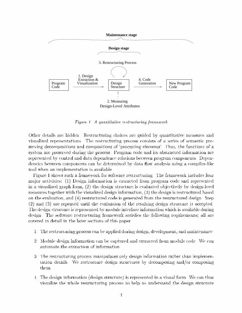
Figure 1. A quantitative restructuring framework
Other details are hidden. Restructuring choices are guided by quantitative measures andvisualized representations. The restructuring process consists of a series of semantic pre-serving decompositions and compositions of `processing elements'. Thus, the functions of asystem are preserved during the process. Program code and its abstracted information arerepresented by control and data dependence relations between program components. Depen-dencies between components can be determined by data ow analysis using a compiler-liketool when an implementation is available.Figure 1 shows such a framework for software restructuring. The framework includes four
major activities: (1) Design information is extracted from program code and representedin a visualized graph form, (2) the design structure is evaluated objectively by design-levelmeasures together with the visualized design information, (3) the design is restructured basedon the evaluation, and (4) restructured code is generated from the restructured design. Step(2) and (3) are repeated until the evaluation of the resulting design structure is accepted.The design structure is represented by module interface information which is available duringdesign. The software restructuring framework satis�es the following requirements; all arecovered in detail in the later sections of this paper.
1. The restructuring process can be applied during design, development, and maintenance.
2. Module design information can be captured and extracted from module code. We canautomate the extraction of information.
3. The restructuring process manipulates only design information rather than implemen-tation details. We restructure design structures by decomposing and/or composingthem.
4. The design information (design structure) is represented in a visual form. We can thusvisualize the whole restructuring process to help us understand the design structure
4

and evaluate alternative designs. A software tool can construct a visual representationfrom a design.
5. Restructured code can be generated from the restructured design.
6. The restructuring decisions are based on objective quantitative criteria for comparingalternative design structures, as well as human intuition guided by graphical represen-tation of modules.
7. The restructuring process can be automated. We can automate design extraction, de-sign visualization, design-level measures, design decomposition/composition, and codegeneration.
3. SOFTWARE DESIGN ABSTRACTIONS
3.1. A Model to Represent Modules
Techniques that help analysts extract design and structure information can support soft-ware reuse (Choi and Scacchi, 1990; Lano and Haughton, 1992; M�uller et al., 1993) byhelping to locate reusable software components from existing (or legacy) systems (Callissand Cornelius, 1989; Esteva and Reynolds, 1991; Ning, Engberts and Kozaczynski., 1993).Abstract models represent modules and relationships between modules, and can serve as abasis for measurement (Baker et al., 1990; Gustafson, Tan and Weaver, 1993).An input-output dependence graph (IODG) models data and control dependence relation-
ships between module interface components (Bieman and Kang, 1998; Kang and Bieman,1996 and 1998). The IODG is adapted from the variable dependence graph introduced byLakhotia (Lakhotia, 1993). Since in this work, a module is a procedure or function, the inter-face components are procedure/function inputs and outputs. Input components are valuesimported either as parameters or referenced global entities. Output components are valuesexported either through reference parameters, values returned by functions, and modi�edglobals. A composite component, such as an array, linked list, or record, is treated as asingle component.We make use of data dependence and two types of control dependence: c-control depen-
dence and i-control dependence, which are derived from the notion of control dependenceused in program dependence graphs (PDG's) (Ottenstein and Ottenstein, 1984). The fol-lowing de�nition assumes the existence of a PDG.
De�nition 1 Dependence Classi�cations
Data Dependence: Output y has a data dependence on input or output x (xd! y)
if x `reaches' y through a dependence path consisting only of data dependenceedges in a PDG.
C-Control Dependence: Output y has c-control dependence on input or output x(x
c! y) if a dependence path between x and y in a PDG contains a control
dependence edge, but no control dependence edges where the source variable
5

is used in a predicate of a loop structure. A c-control dependence between
an input and an output indicates that the output value is controlled by the
input value through a decision structure.
I-Control Dependence: Output y has i-control dependence on input or output x
(xi! y) if a dependence path in a PDG between x and y contains a control
dependence edge which includes a variable used in a predicate of a loop
structure. When an output has i-control dependence on an input, the output
value is a�ected by the execution of a iteration process whose execution count
is determined directly or indirectly by the input.
I/O Direct Dependence: Output y has data, c-control, and/or i-control I/Odirect dependence on input or output x if y has a data dependence on x, and
there is no other input or output on the dependence path between x and y.
De�nition 1 is simpli�ed from our prior work (Kang and Bieman, 1996 and 1998; Biemanand Kang, 1998). Compiler texts provide more formal de�nitions of the notion of depen-dence (Zima and Chapman, 1991, pp. 112{172). The IODG is de�ned in terms of the inputoutput components and their dependencies.
De�nition 2 Input-Output Dependence Graph (IODG).
The IODG of module M is a directed graph, GM = (V, E) where V is a set of
input-output components of M, and E is a set of edges labeled with dependence
types such that E = f(x; y) 2 V � V j y has data, c-control, and/or i-control
I/O direct dependence on xg. Each vertex in an IODG is labeled with one of �ve
types: in-parameter, out-parameter, in-global, out-global, and function-return.
The IODG is an abstraction of a PDG. It is a PDG without nodes and edges representinginternal dependencies. In addition, the IODG classi�es control dependencies as i-controlor c-control. Figure 2 depicts two IODG's, one for procedure Tsale Tpay and another forprocedure Sale Pay Profit. Sale Pay Profit gets a sale record from a �le and computesthe pay and pro�t from the sale record by calling procedure Tsale Tpay.The �gure shows that a graphical display of the IODG can make a module's interface easy
to visualize. We extend the IODG to represent a caller-callee relationship by including theinput-output dependence relationship of the callee inside the IODG of the caller. A circlerepresents a parameter input, and a square represents an output and function-return. Adashed circle indicates a global input and a dashed square represents an output. The textsin each circle and square are the names of input and output variables. Each arrow indicatesthe dependence between two components.The extended IODG contains the complete dependence paths between inputs and out-
puts of a module. Thus, we can determine exact dependence relationships between in-put/output components. For example, consider input days and output pay of the IODG
of Sale Pay Profit. We �nd three dependence paths between them: (1) daysd! pay,
(2) daysd! input parameter
i! output parameter
d! pay, and (3) days
i! sale
d!
input parameterd! output parameter
d! pay. According to our dependence de�nitions,
6

days
d di i
sale
tpaytsaled
di
i
costfiledays
sale
pay profit
tpay : float;
begin
var sale : int_array;
begin
var i : integer; var tpay : float );
tsail := 0; tpay := 0;
tsale := tsale + sale[i];
if sale[i] > 1000 then tpay := tpay + 50; end;end;
tpay := tpay + 0.1 * sale[i];
var tsale : integer; sale : int_array;
procedure Tsale_Tpay ( days : integer;
for i := 1 to days do begin
var pay : float; var profit : float );
end;
end;
pay := tpay / days + 100; profit := 0.9 * tsale - cost;
Tsale_Tpay(days, sale, tsale, tpay);
var i, tsale : int;
reset(file); i := 0;
i := i + 1; while i > days do begin
readln(file, sale[i])
cost: float; ( days: integer; file: text;procedure Sale_Pay_Profit
d d
dTsale_Tpay
i d
d d
d
Figure 2. Input-output dependence graph representation for Tsale Tpay and Sale Pay Profit
pay has data and i-control dependencies on days. Indirect dependences are implied by asequence of direct dependences. The IODG of Sale Pay Profit in Figure 2 shows that thedirect and indirect dependence relationship between three inputs and two outputs.
3.2. A Model to Represent Relationships between Modules
Several models capture the relationship between modules. A well known model is a call-
graph which represents a call relationship between modules. Weiser de�nes a concept ofinterprocedural dependences using control and data dependencies in the context of producingslices of programs (Weiser, 1994). The interprocedural slices do not include the call relation-ship between procedures. Loyall and Mathisen de�ne a model that captures inter-proceduralcontrol and data dependences (Loyall and Mathisen, 1993). They use the model to performdependence analysis for determining e�ects of software modi�cations and support automatedtest and coverage analysis.We model the relationship between modules in a system with a module interconnection
graph (MIG). The model is based on the control, data ow relationship, and call relationshipbetween modules of a system. In the model, there are four types of relationships betweentwo modules:
1. common relation: a module sends information to another through a global compo-nent; a module writes a variable, a compound variable, or data �le, which in turn isread by another module,
2. call relation: a module imports another module's computation to execute its func-tions; a module calls another module,
3. sequential relation: an output of a module is passed to another module as an input;an output of a module is used as an input of another module, and
7
m6
(b)
m4
m8
m9
m5
m1
m2 m3 m7
(iv) No relation(iii) Sequential relation(ii) Call relation(i) Common relation
(a)
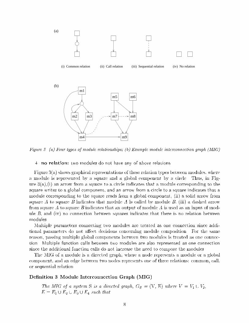
Figure 3. (a) Four types of module relationships; (b) Example module interconnection graph (MIG)
4. no relation: two modules do not have any of above relations.
Figure 3(a) shows graphical representations of these relation types between modules, wherea module is represented by a square and a global component by a circle. Thus, in Fig-ure 3(a),(i) an arrow from a square to a circle indicates that a module corresponding to thesquare writes to a global component, and an arrow from a circle to a square indicates that amodule corresponding to the square reads from a global component, (ii) a solid arrow fromsquare A to square B indicates that module A is called by module B, (iii) a dashed arrowfrom square A to square B indicates that an output of module A is used as an input of mod-ule B, and (iv) no connection between squares indicates that there is no relation betweenmodules.Multiple parameters connecting two modules are treated as one connection since addi-
tional parameters do not a�ect decisions concerning module composition. For the samereason, passing multiple global components between two modules is treated as one connec-tion. Multiple function calls between two modules are also represented as one connectionsince the additional function calls do not increase the need to compose the modules.The MIG of a module is a directed graph, where a node represents a module or a global
component, and an edge between two nodes represents one of three relations: common, call,or sequential relation.
De�nition 3 Module Interconnection Graph (MIG).
The MIG of a system S is a directed graph, GS = (V, E) where V = V1 [ V2;
E = E1 [ E2 [ E3 [ E4 such that
8

V1 = a set of modules of S,V2 = a set of global components of S,E1 = f(x; y) 2 V1�V1 j x is invoked by y through a function call (call relation)g,
E2 = f(x; y) 2 V1 � V1 j an input of y has a dependence on an output of x
(sequential relation)g,
E3 = f(x; y) 2 V1 � V2 j x writes to yg, and
E4 = f(x; y) 2 V2 � V1 j y reads xg.
When a MIG is displayed graphically, an edge E2 (sequential relation) is represented bya dashed line and the other edges by solid lines. The MIG can be generated automaticallyfrom program code or can be determined during the design stage. When program code isavailable, the relation types can be determined by dependence analysis using a compiler-liketool. During the design stage, the information about global components, function-calls, andcaller-callee relationships should be available.Figure 3(b) shows an example of a MIG representation of a system. The MIG shows
the relationship between modules of a system. In its graphical form, the MIG visuallydisplays the system's organization. This representation is used to de�ne design-level couplingmeasures and is applied to software restructuring.Analysts can use the visualized IODG and MIG representations to help them understand
the design structure of program. The IODG shows input-output components of a module. Italso shows how the input-output components are related through dependence information.The MIG shows system components, modules and global structures, and the relationshipbetween the components. The IODG and MIG representations can be used to recapturedesigns from existing, possibly legacy, systems.When program size is large or program structure is complex, program understanding by
reading code is a painful process. It is not easy to glean program functionalities by readingprogram code. The IODG and MIG information is much more compact than program code.IODG size is not proportional to program size; it is related to the size of a procedure'sinterface, not its body.
4. DESIGN MEASURES
4.1. Measuring Design Cohesion
Design-level cohesion and coupling measures guide restructuring in the proposed frame-work. Measures identify modules that may be restructured by decomposition|splitting intotwo or more modules|or by composition|merging with other modules. We develop a setof design-level cohesion and coupling measures based on the IODG and MIG design-levelmodule abstractions. The representation condition of measurement theory requires that,in deriving a measure of an attribute, the empirical relations of the attribute should bepreserved in the numerical relation system (Fenton, 1994). We �rst de�ne intuitive rela-tions and derive measures in terms of those relations. This approach is consistent withthe model-order-mapping paradigm for specifying software measures (Gustafson, Tan andWeaver, 1993).
9

Stevens, Myers, and Constantine (1974) de�ne software cohesion (\SMC Cohesion") as aproperty that can be used to help determine if the components of a module actually belongtogether. Based on the properties of the associations between each pair of processing elementsin a module, SMC Cohesion de�nes seven cohesion levels on an ordinal scale: coincidental,temporal, procedural, communicational, sequential, and function cohesion. Experts use theirintuition to determine the SMC Cohesion of a component. Because of this dependenceon intuitive judgement, SMC Cohesion cannot be readily applied to measure cohesion inpractice (Nandigam, Lakhotia and �Cech 1999; Woodward, 1993).In prior work, we applied SMC Cohesion directly to the IODG of a module to derive
a design-level cohesion (DLC) measure (Kang and Bieman, 1996 and 1998) satis�es therepresentation condition of measurement (Fenton and P eeger, 1997, pp. 23{72). The DLCmeasure derivation is based on the IODG; we use the approach used to de�ne SMC Cohesionand by Lakhotia to de�ne module cohesion (Lakhotia, 1993). Here, we brie y de�ne the DLCmeasure. Detailed derivations of DLC are found in prior papers (Bieman and Kang, 1998;Kang and Bieman, 1998).The DLC measure is ordinal; a module exhibits one of six cohesion \levels." These levels
are based on six relations between module output pairs. The levels and relations are designedto be consistent with the di�culty of splitting a module.
De�nition 4 Module Output Relations.
1. Coincidental relation (R1): Two outputs have no dependence relationship
with each other and no dependence relation on a common input (Lakhotia,
1993).
2. Conditional relation (R2): Two outputs are c-control dependent on the
same input.
3. Iterative relation (R3): Two outputs are i-control dependent on the same
input.
4. Communicational relation (R4): Two outputs are dependent on a com-
mon input. This input is used to compute both outputs, but the two outputs
are not c-control or i-control dependent on this input (Lakhotia, 1993).
5. Sequential relation (R5): One output is dependent on the other out-
put (Lakhotia, 1993).
6. Functional relation (R6): There is only one output in a module.
These six relations are on an ordinal scale; cohesion strength increases from R1 to R6.Like Lakhotia's module cohesion measure (Lakhotia, 1993), DLC measurement is based onthe pair of outputs with the weakest association.
De�nition 5 Design-Level Cohesion (DLC) Measure Calculation.
Determine the strongest relation for each pair of outputs. The DLC value of the
module is the weakest (lowest level) relation of the set of strongest relations for
each pair.
10
Coincidental cohesion
d ii d
Conditional cohesion
ddi ic c
flag
Iterative cohesion
d di i
Communicational cohesion
ddi i
Sequential cohesion
d
dd
i
Functional cohesion
di
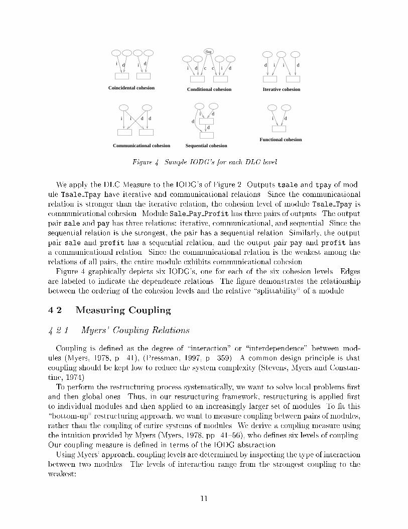
Figure 4. Sample IODG's for each DLC level
We apply the DLC Measure to the IODG's of Figure 2. Outputs tsale and tpay of mod-ule Tsale Tpay have iterative and communicational relations. Since the communicationalrelation is stronger than the iterative relation, the cohesion level of module Tsale Tpay iscommunicational cohesion. Module Sale Pay Profit has three pairs of outputs. The outputpair sale and pay has three relations: iterative, communicational, and sequential. Since thesequential relation is the strongest, the pair has a sequential relation. Similarly, the outputpair sale and profit has a sequential relation, and the output pair pay and profit hasa communicational relation. Since the communicational relation is the weakest among therelations of all pairs, the entire module exhibits communicational cohesion.Figure 4 graphically depicts six IODG's, one for each of the six cohesion levels. Edges
are labeled to indicate the dependence relations. The �gure demonstrates the relationshipbetween the ordering of the cohesion levels and the relative \splittability" of a module.
4.2. Measuring Coupling
4.2.1. Myers' Coupling Relations
Coupling is de�ned as the degree of \interaction" or \interdependence" between mod-ules (Myers, 1978, p. 41), (Pressman, 1997, p. 359). A common design principle is thatcoupling should be kept low to reduce the system complexity (Stevens, Myers and Constan-tine, 1974).To perform the restructuring process systematically, we want to solve local problems �rst
and then global ones. Thus, in our restructuring framework, restructuring is applied �rstto individual modules and then applied to an increasingly larger set of modules. To �t this\bottom-up" restructuring approach, we want to measure coupling between pairs of modules,rather than the coupling of entire systems of modules. We derive a coupling measure usingthe intuition provided by Myers (Myers, 1978, pp. 41{56), who de�nes six levels of coupling.Our coupling measure is de�ned in terms of the IODG abstraction.Using Myers' approach, coupling levels are determined by inspecting the type of interaction
between two modules. The levels of interaction range from the strongest coupling to theweakest:
11

1. Content Coupling: One module references the contents of the other, i.e., one branchesinto a label of the other, modi�es a statement of the other, or changes local data ofthe other.
2. Common Coupling: Two modules have access to the same global data.
3. Control Coupling: One module passes a ag as parameter to control the logic of theother.
4. Stamp Coupling: Two modules use a common data structure but may operate ondi�erent portions of the data structure.
5. Data Coupling: One module passes simple data or a data structure as a parameter tothe other. All components of the data structure are used by the called module.
6. No Coupling: There is no communication between two modules.
A general design goal is to avoid the strongest forms of coupling. Myers' coupling, like SMCcohesion, is di�cult to determine because of its subjective nature (Woodward, 1993). We useMyers' coupling levels as an empirical relations system to validate our design-level couplingmeasure.
4.2.2. A Design-Level Coupling (DCP) Measure
Our DCP measure is de�ned by examining coupling exhibited by the MIG and IODGrepresentations of modules following a similar approach to that used by Myers. The couplingbetween two modules is classi�ed by �ve relations which are ordered from strongest toweakest:
1. Common Coupling: In the MIG representation, two modules have a common re-lation when one module writes to a global data and the other reads from the globaldata. In the IODG representation, common coupling exists when two IODG's containthe same global data and one IODG has the global data as an input component andthe other IODG has it as an output component.
2. Conditional Coupling: Conditional coupling occurs when, in the MIG representa-tion, two modules have a call relation and in the IODG representation, one modulepasses a parameter to another module, and the parameter has c-control dependence onan output component. Conditional coupling includes Myers' control coupling since a ag is implemented as an `if-then-else' predicate component and a ag in an IODG rep-resentation always has `c-control dependence' on an output. However, since a compo-nent with c-control dependence is not always a ag, DCP conditional coupling includessome cases of Myers' stamp, and data coupling.
3. Computational Coupling: Computational coupling occurs when, in the MIG rep-resentation, two modules have a call relation and in the IODG representation, onemodule passes a parameter to another module, and the parameter has i-control ordata dependence on an output component. Computational coupling corresponds toboth Myers' stamp and data coupling, since whenever data or a data structure that is
12

not used as a ag is passed through parameter, it has i-control or data dependence. Wecannot di�erentiate between a data structure and a simple data input, because in anIODG an input-output component is represented by its name but not by its contents.
4. Sequential Coupling: Two modules have a sequential coupling when, in the MIGrepresentation, outputs of one module are used as inputs of the other module (sequen-tial relation). In the IODG representation, the output components of an IODG areinput components of the other IODG. Sequential coupling is classi�ed as no-couplingby Myers since there is no connection through parameter passing or global data. Thus,the connection strength is weaker than Myers' data coupling but stronger than or thesame as Myers' no coupling.
5. No Coupling: Two modules have no coupling when there are no connections be-tween the MIG representation of two modules. There is no coupling when, in theIODG representation, there is no global data sharing and no function-calls betweentwo modules.
A pair of modules may have several connections. Since we want to apply the couplingmeasure to software restructuring, we represent multiple connections between modules bythe corresponding multiple coupling levels of the modules. Fenton and Melton merge boththe connection kind and the number of connections between a pair of modules in theirde�nition of a coupling measure (Fenton and Melton, 1990). They choose the strongest(least desirable) level of coupling when there are multiple connections between two modules.We cannot apply Myers' content coupling in our framework since the IODG cannot repre-
sent direct references to the contents of another module (content coupling primarily occurs inassembly language programming). We introduce a new level of coupling, sequential coupling,where the output of one module is used as input of the other. Though the two modules areindependent when inspecting them in isolation, they have a caller-callee relationship fromthe perspective of the control module.We can always determine the DCP measure based on the MIG and IODG information.
When program code is available, the MIG and IODG can be generated automatically fromthe analysis of control and data dependence between program components using a compiler-like tool. Without code, a designer must specify the dependencies between input and outputcomponents of IODG and the relationship between modules of MIG.Since the derivation of the DCP measure is consistent with the intuition used to de�ne
Myers' Coupling, we assume the following ordering of the �ve DCP relation levels:
Common > Conditional � Computational > Sequential � No Coupling (1)
The DCP measure is on an ordinal scale as long as we accept the ordering implied by therelations of Myers' Coupling.
13

O1
I I21
M1
O2 O
I
M2
1
1 O
I
2
M3
2
O
I
M2
1
1
M1
O1 O
I1
2 O
I
2
M3
1
O1
O2
I1
O1
I
M2
1I2
O2
M3
I1
O2
O1
O2
M1
O
I1
1
M2M2
M1
I1
1 M2M1 :OD4
M2, M3{ }M1D1
M2, M3{ }M1D2
O2O2
I1
O2
M2, M3{ }
(c)
(d)
(e)
(f)
(a)
(b)
M1
M1C1
M2, M3{ }M1D3
I1
O1
I1
O1
M1 M2M1 M2
H(
R(M1 M2
O1)
O1)
M2
O
I1
1
M1M1
O
I1
M2
2
M2C2
{ }M1, M2
Figure 5. Restructuring Operations (from Kang and Bieman (1996)); edge labels are not included
5. SOFTWARE RESTRUCTURING
5.1. Basic Restructuring Operations
Restructuring is completed by applying restructuring operations. The restructuring pro-cess is guided by the DLC and DCP measures and the intuition provided by the graphicallydisplayed IODG and MIG models.Basic restructuring operations can either compose (merge), decompose (split), or reorga-
nize modules. Individual decomposition operations can be applied to modules with speci�cDLC cohesion levels. Conversely, the application of composition operations depends onthe DCP coupling of module pairs. Modules can also be restructured to hide componentswith greater visibility than necessary. We use eight basic operations, shown in Figure 5, torestructure modules (Kang and Bieman, 1996):Coincidental Decomposition (D1): A module exhibiting coincidental cohesion has disjoint
components|one or more groups of data tokens linked to individual outputs withoutany dependence relations on another group. These modules can be easily split byseparating the disjoint groups as shown in Figure 5(a).
CIC Decomposition (D2): Modules with conditional, iterative, or communicational cohesionhave one or more inputs tied to all of the outputs. These modules can be decomposedby copying all data tokens linked to more than one output as shown in Figure 5(b).
Sequential Decomposition A (D3): In modules with sequential cohesion one or more outputs
14

depend on other outputs. Such modules can be decomposed by splitting the modulesinto two or more modules with sequential coupling, which is one of the most desiredforms of coupling. The output of a module (producer module) is used as the input ofthe other (user module) as shown in Figure 5(c).
Sequential Composition (C1): The inverse of sequential decomposition is to compose twomodules with sequential coupling (also shown in Figure 5(c)).
Sequential Decomposition B(D4): An alternative to operation D3, Sequential Decomposi-tion A, is to replace an output component with a module call, and move the outputcomponent and the components that it depends on into a separate callee module asshown in Figure 5(d).
Caller/Callee Composition (C2): Two modules can be composed if they have a call relation,exhibit either conditional or computational coupling, and the callee has only one caller.The call statement is replaced by the tokens of the callee, and unnecessary coupling isreduced. Figure 5(e) shows operation C2.
Hide (H): The hide operation, shown in Figure 5(f), converts an exported output into ahidden local variable, when the exported output is not actually used externally.
Reveal (R): Reveal, also shown in Figure 5(f), is the inverse of hide. Using reveal, R(M1:O1),a local variable O1 of M1 is exported by changing the local variable into an outputvariable. Reveal can be used to separate a hidden function from a large module.
5.2. Restructuring Process
A software restructuring process provides guidance for determining when to apply indi-vidual restructuring operations. Systematic restructuring process can improve cohesion andcoupling attributes of a system. An appropriate restructuring will: (1) locate the mod-ules with low cohesion levels and determine which are the poorly-designed modules amongthem, (2) decompose the modules identi�ed as a poorly-designed ones, and (3) locate overlydecomposed (i.e., overmodularized) modules that increase the coupling of the system, andrecompose them.During restructuring, decomposition should precede composition because of the poten-
tial existence of partially-used modules|modules where each output component is used bydi�erent modules. The decomposition process converts a partially-used module into a fully-used module. Composition of fully-connected modules does not decrease module cohesion.To perform restructuring systematically, we solve local problems �rst and then global ones:restructuring is applied �rst to each module and then expanded to a larger set of modules.An improvement in one software attribute can deteriorate other attributes. The opti-
mal cohesion and coupling levels will depend on the application, the required reusability,readability, and maintainability of software. Restructuring should be performed objectivelyso that both cohesion and coupling measures of software are improved, and at least bothmeasures do not become worse.The six step restructuring process that we proposed in (Kang and Bieman, 1996 and 1998)
can be applied to procedures Tsale Tpay and Sale Pay Profit in Figure 2:
15

1. Generate IODG's of candidate modules. IODG's can be constructed solely from designinformation. If a formal design notation is used, they can be generated automaticallyby a tool. If the code for modules already exists, the information necessary to constructthe IODG's can be extracted from the code using a compiler-like tool. Figure 2 showsthe IODG's of procedures Tsale Tpay and Sale Pay Profit. System 1.1 in Figure 6also depicts these IODG's.
2. Compute DLC levels. The IODG's for procedures Tsale Tpay and Sale Pay Profit
in System 1.1 in Figure 6 both exhibit communicational cohesion.
3. Locate modules with low DLC levels and identify restructuring subjects. Low DLClevels indicate modules with multiple independent functions. If the policy is to aim forfunctional cohesion, restructure both Tsale Tpay and Sale Pay Profit of System 1.1in Figure 6. Both modules perform multiple functions.
4. Decompose the IODG of each identi�ed restructuring subject using the following pro-cedure:
(a) Partition the output components of the IODG so each resulting IODG has ahigher DLC level. An optimal partition can be identi�ed by computing DLCvalues for all possible partitions, since the number of module output componentsis generally limited to a tractable number.
(b) Decompose each IODG according to the partition of IODG outputs. ResultingIODG's include input-output components with dependence relations with thepartitioned outputs.
Use a bottom-up approach to decompose two IODG's with a caller-callee relationship|examine the callee �rst. Change the corresponding invocation in the caller to re ectthe callee's decomposition, and then apply the decomposition to the caller. Thus, wedecompose Tsale Tpay before we decompose Sale Pay Profit.
Repeat Step 4 until the DLC level of each resulting IODG is acceptable, or there areno further candidates for decomposition.
In the example shown in Figure 6, Tsale Tpay is called by Sale Pay Profit. Thus, thedecomposition of procedure Tsale Tpay a�ects the code of its caller Sale Pay Profit;a modi�ed IODG of Sale Pay Profit re ects this change. We �rst decompose Tsale Tpay
using restructuring operation D2, CIC Decomposition, producing two modules, Tsaleand Tpay. We also modify the caller, Sale Pay Profit, to invoke the modi�ed callee.This restructuring step is shown as transition R2 in Figure 6, producing System 1.2.Procedures Tsale and Tpay both exhibit functional cohesion, while the cohesion levelof Sale Pay Profit remains unchanged.
We apply restructuring operation D2 again, as shown in Figure 6 as transition R3. Thistime we split Sale Pay Profit into Sale Pay and Sale Profit producing System 1.3.Both new modules exhibit sequential cohesion.
16

tpay
sale
sale
n
n
d
di
i
tsale
Tsale
Tpaysale
tsale tpay
days
ddi i
Tsale_Tpaysale
profit
cost
pay
dd
ii
costfiledays
sale
pay profit
days
R5
cost
profit
saledays
days
ifile
sale
Sale
dtpay
dayssale
Tpay
i d
dayssale
tsale
Tsale
i d
R6
pay
sale
profit
days file days file
cost
tpay
dayssale
dayssale
tsale
Tsale
Tpay
i d
i d
sale
pay
saledays
Pay
days
ifile
sale
Sale
d
dayssale
cost
profit
Profit
i dd
dayssale
Program code
System1.1 System1.2
R1
R3
DLC(DLC(DLC( ) = functional cohesionDLC( ) = functional cohesion
DLC of every module is functional cohesion.
DCP(DCP( ) = computational coupling
in Figure 2.
DLC(DLC(
) = communicational cohesionTsale_Tpay
DLC(communicational cohesion
DLC( ) = functional cohesionDLC( ) = functional cohesionTsale
Tpay
TsaleTpay
Sale_Pay_Profit ) = communicationalcohesion
Sale_Pay_Profit
Sale_Pay_Profit ) =
Sale_PaySale_Profit ) = sequential cohesion
) = sequential cohesionTpay, Pay
ProfitTsale,) = computational coupling
System1.4
Sale_Pay_Profit
d d
di
Tsale Tpay
d i
d d
dTsale_Tpay
d d
d d
System1.5
{
R6: Generate program code.
R2:
R1: Generate IODG’s.
R3:
R4:
R5:
Restructuring steps :
{
{
{ }
Tsale_Tpay
Sale_Pay_Profit
Sale_Pay
Sale, Profit
{ }D2
D2
D3
D3{
}C2
Pay
ProfitC2
Sale_Pay, Sale_Profit }
Tsale, Tpay
Sale, Pay }
Sale, Profit }
Tpay, Pay
Tsale, Profit
i fileid
d
d
di
Tpay
Profit
d
d
DLC of every module is functional cohesion.
R2
d d
ddd
System1.3
Sale_Pay
d
d
di
Tsale
di
Sale_Profit
Tpay d
d
R4d
d
di
dTsale d
d
d
d d
dd
i
d
i
d
Pay
Pay
d,i
Program
Figure 7.code in
There is no computational coupling between modules.
Figure 6. Restructuring procedures Tsale Tpay and Sale Pay Profit of Figure 2
17

We repeat the process using operation D3 (transition R4) on both Sale Pay andSale Profit producing modules Sale, Pay, and Profit in System 1.4. After com-pleting transitions R2, R3, and R4, all of the modules exhibit functional cohesion. Wenow examine coupling to consider candidates for composition.
5. Locate unnecessarily decomposed modules and compose them. After repeated decom-positions, a system can become overmodularized, resulting in too much interactionbetween modules and an increase in coupling. The DCP between each pair of modulescan identify overmodularized modules. Apply composition operations to overmodular-ized modules only when composition does not decrease their cohesion levels and doesnot a�ect connections with other modules.
We apply the DCP measure to the module pairs in System 1.4 of Figure 6 and �ndcomputational coupling between procedure Tsale and Profit, and Tpay and Pay,and sequential coupling between procedure Sale and Pay, and between Sale andProfit. The computational coupling is removed by applying composition operatorC2, Caller/Callee Composition, as shown in transition R5 producing System 1.5. Allof the modules in System 1.5 exhibit functional cohesion, and there is no computationalcoupling.
6. Generate module code (if the original IODG's were generated from source code). A toolcan automate code generation by using the data tokens and the dependence informationobtained from the initial modules during step 1.
Transition R6 in Figure 6 represents the generation of new code for the example mod-ules. The resulting restructured modules are given in Figure 7. At the start of therestructuring process, both modules exhibit communicational cohesion and computa-tional coupling. The modules are restructured into three modules that exhibit func-tional cohesion, the strongest cohesion level and sequential coupling, the weakest cou-pling. The restructured modules should be easier to understand, maintain, and reuse.
Coupling plays a limited role in our framework since a composition of modules mustconsider other factors in addition to coupling. For example, future reuse: if a module islikely to be reused, we should not hide the module by composing into other modules. Weuse coupling as a supplementary measure and cohesion as a primary one.At the start of the restructuring process, both modules in Figure 2 exhibit communica-
tional cohesion and computational coupling. These two modules are restructured into threenew modules. The restructured modules, shown in Figure 7, exhibit functional cohesion,the strongest cohesion level and sequential coupling, the weakest coupling. The restructuredmodules should be easier to understand, maintain, and reuse.
6. RESTRUCTURING TOOLS
Our software restructuring framework includes four major processes: (1) the design infor-mation of modules is extracted from module code and represented in a visualized graph form;
18

begin
end; end;
var sale : int_array ); file: text;
procedure Sale ( days: integer;
var i : integer;
reset(file); i := 0; while i < days do begin i := i +1; readln(file, sale[i])
begin
sale : int_array;
var i, tpay : integer;
for i := 1 to days do begin
var profit : float );
cost: float; ( days : integer; procedure Profit
tsale := 0;
tsale := sale + sale[i]; end;
end; profit := 0.9 * tsale - cost;
begin
procedure Pay ( days : integer; sale : int_array; var pay : float );var i, tpay : integer;
tpay := 0; for i := 1 to days do begin tpay := pay + 0.1 * sale[i]; if sale[i] > 1000 then tpay := tpay + 50; end; pay := tpay / days + 100;end;
Figure 7. Procedures produced after restructuring the procedures of Figure 2
(2) the design structure is evaluated objectively by design-level measures; (3) the design isrestructured based on the measures; and (4) the restructured code is generated from therestructured design.We have developed tools to support the restructuring process using lex and yacc from
the gcc compiler. The tools process C programs in a UNIX workstation environment. Theyhave been installed and tested for SUN SPARCstatations running SUN-OS and IBM RS6000systems running AIX. Key components of the restructuring tool include the following:
1. Control Flow Graph Generator: Vertexes of this graph are module statements. C out-put variables are identi�ed, including modi�ed global variables, reference arguments,and function return values.
2. Data Token Identi�er: Identi�es all de�ned and used data tokens of each statement ina module, and all local variables and output variables.
3. Dependency Analyzer: Computes data dependencies and control dependencies for datatokens in module statements, and identi�es control dependencies involving loop pred-icates.
4. F-Slicer: Generates program (also data) slice information for a module. A program
slice is the portion of program text that a�ects a speci�ed program variable (Weiser,1994): Bieman and Ott (1994) de�ned a data slice for a data token as the sequence ofall data tokens in the statements that comprise the \backward" and \forward" slicesof the data token.
5. IODG tool: Generates IODG information with only input and output componentsusing program slice information generated by the F-Slicer.
6. DLC tool: Computes the DLC measure using the IODG information.
7. Decomposition Tool: Performs decomposition using the slice information and IODG.
19

8. Coupling Analyzer: MIG information and a DCP tool can be easily constructed fromcall graph and data ow information. To build a composition tool, in addition tothe call graph and data ow information, we need to consider the details of programconstructs, such as declarations, globals, and variable names.
Our FUNCO tool set is a metrics analyzer for C programs that integrates the above toolcomponents. Prototypes for components 1{6 are operational. We use information generatedby the F-Slicer for component 7. However, the F-slicer is not designed to automaticallygenerate source code slices, so the process is labor intensive. Existing slicing tools canpotentially automate component 7 (Gallagher and Lyle, 1991; Jackson and Ladd, 1994).The current version of Unravel, a C-slicer, is capable of producing compilable slices (Lyleet al., 1995), so it is a good candidate for component 7. A coupling analyzer is now underconstruction. FUNCO also includes an implementation of the functional cohesion measurede�ned by Bieman and Ott (Bieman and Ott, 1994). FUNCO has been installed and testedfor SUN SPARC workstations running SUN-OS and IBM RS6000 systems running AIX. Itis available for general use on the World Wide Web (Kang and Bieman, 1997).
7. RESTRUCTURING CASE STUDY
7.1. Limitations
We restructure a small software system to demonstrate the restructuring process andto evaluate how e�ectively the process can be applied to real software. The IODG toolgenerated IODG information from program code and the DLC tool measured DLC levelsfrom the IODG information. We generated visual IODG representations manually from theIODG information to provide further intuitive information.When this study was conducted, the available version of Unravel could not generate com-
pilable slices. Thus, for this case study, we used the F-Slicer tool to help perform the de-composition operation. The F-Slicer tool provides program slice information from programcode. Decomposition decisions were based on the IODG representation and DLC measure-ment. We generated the restructured program code by selecting a program slice or slicesthat correspond to one or more output components of each restructured IODG.
7.2. Applying the Restructuring Process
The data for the case study was the JASMIN software system (Bieman and Zhao, 1995).JASMIN is a research tool that collects data concerning the use of inheritance in C++software. JASMIN measures the depth of the inheritance, number of classes with/withoutprivate sections, number of classes derived from classes with/without private sections, andnumber of private, public, and multiple inheritances. JASMIN contains 39 C functions and4540 lines of source code. On average, each function has 4.69 inputs, 2.26 outputs, and 66.95data tokens.We applied the restructuring process to the JASMIN system following the steps given in
Section :
20

after_parent
private
class_tree pre_class
class_from_parent
pre_class
class_from_parent
c_name
add_class
i ic
Figure 8. An IODG representation of function add class
1. Generate IODG's: The IODG tool generated IODG information from JASMIN sourcecode. Figure 8, Figure 9, and Figure 10 show example IODG representations forfunctions add class, print info, and print summary respectively. The Appendixincludes the program code for function print info.
2. Compute DLC levels: The DLC tool computed DLC levels for each generated IODG.We found 22 functions with functional cohesion, 3 functions with sequential cohesion,11 functions with communicational cohesion, and 3 functions with coincidental cohe-sion. No functions exhibit conditional or iterative cohesion. Actually, many JASMINoutput components exhibit conditional or iterative associations. However, those associ-ations are hidden by other stronger associations, such as communicational association.
3. Determine restructuring candidates among functions with low DLC levels: Among thethree coincidental functions, one function initializes a tree data structure, and relatedglobal variables. This function actually exhibits temporal cohesion according to theoriginal SMC Cohesion criteria (Stevens, Myers and Constantine, 1974), which is acohesion category not supported by the DLC measure. Our examination eliminatesthis function from the restructuring process. Both of the two remaining coincidentalfunctions, add class and tg add class, contain two related outputs and an isolatedoutput that is used for computation control purpose. We restructure these two coinci-dental functions since they unnecessarily include a control variable.
Among the 11 functions exhibiting communicational cohesion, two functions, print info
and print summary, include loosely connected outputs|they generate output �les thatare not tightly related to each other. We restructure these functions because of theweak relationship between their output �les. Figure 8, 9, and 10 show IODG's forthree of the restructuring candidates.
4. Decompose the IODG of each module identi�ed as a poorly-designed one: We applyappropriate decomposition operations:
R1 : add classD1�! fadd class; tempg
R2 : tg add classD2�! ftg add class; tg tempg
R3 : print infoD3�! fprint inh info; print outputg
21

verbose
depthpublic_inh
private_inhclass_treeflag child_count
print_it
string
i,d i,d i i,dc
c c
print_info
output std_output
Figure 9. An IODG representation of function print info
filename
minmaxmedianmean
columnsrows
class_tree
stat1classtable
output
stat1classtable stat2classtable
stat2classtable
stat
i i iii,d
i
i i,c i,c
print_summary
Figure 10. An IODG representation of function print summary
22

flag class_tree
c
string
print_inh_info
verbose
depthpublic_inh
private_inhclass_tree child_count
i,d i,d i i,d
c
print_output
output std_output
(a) (b)
Figure 11. (a) shows IODG print inh info and (b) shows IODG
print output; they are IODG's decomposed from IODG print info
R4 : print summaryD3�! fprint stat1; print stat2; print out summaryg
We decompose IODG add class into two IODG's. One, also named add class, in-cludes two output components, class tree and pre class. The other IODG, temp,includes only one output component, class from parent. In the new add class func-tion, class from parent is assigned a constant value. We will later compose temp withits caller(s). The new add class IODG exhibits sequential cohesion and IODG temp
exhibits functional cohesion. Following a similar procedure, IODG tg add class isdecomposed into IODG tg add class and IODG tg temp.
IODG print info has two tightly connected output components, output and std output.Another output, string, is loosely connected with the other outputs. We decom-pose IODG print info into IODG print inh info and IODG print output, asshown in Figure 11. IODG print inh info exhibits functional cohesion and IODGprint output exhibits communicational cohesion.
IODG print summary contains three output components that are loosely connected.Two outputs, stat1classtable and stat2classtable, could be placed into the sameIODG or separated into individual IODG's. This decision depends on the detailed andconceptual relationship between two outputs and the software application. We decom-pose IODG print summary into three new IODG's, print stat1, print stat2, andprint out summary. Figure 12 displays these IODG's. The IODG of print out summary
omits an invocation of stat. All of the new IODG's in the Figure 12 exhibit functionalcohesion.
In applying the decompositions, we change the invocations in caller IODG's to re ectthe callee's decomposition. For example, function add class is called by functionadd parent, and thus, an invocation of add class in add parent is replaced by two
23

class_tree
stat1classtable
print_stat1
(a)
class_tree
print_stat2
stat2classtable
(b)
stat1classtable
stat2classtableclass_tree
output
print_out_summary
c,i,d
(c)
Figure 12. (a) shows IODG print stat1, (b) IODG print stat2, and (c) IODG
print out summary; they are IODG's decomposed from IODG print summary
invocations of add class and temp.
5. Locate unnecessarily decomposed modules and compose them: We apply compositionoperations:
R5 : fadd parent; tempgC1�! add parent
R6 : fmain; tg tempgC2�! main
IODG temp is called from three functions (call-couplings), but used only in IODGadd parent. Note that temp includes a global variable assigned with a constant value.Thus, we combine temp into IODG add parent and remove the invocations in theother functions. IODG tg temp is called and used only from IODG main, and thus,we also combine tg temp into IODG main.
6. Generate program code from the restructured IODG's: Program code is generatedfrom each corresponding IODG. The Appendix includes program code correspondingto IODG print inh info and IODG print output.
Through restructuring, two functions exhibiting coincidental cohesion have been convertedinto functions with sequential cohesion, one function exhibiting communicational cohesionwas decomposed into a function with communicational cohesion and a function with func-tional cohesion, and another function with communicational cohesion has been decomposedinto three functions with functional cohesion.
7.3. Restructuring Results
At the end of the process, we had restructured six functions, creating nine new func-tions. The restructuring process included �ve decompositions and two compositions. Allrestructuring decision were based on the IODG's and DLC/DCP values.
24

Table 1. Properties of the Restructured Functions in the JASMIN System, Before Restructuring.
Original No. of No. of No. of No. of No. of
Functions inputs outputs lines nodes edges V(g) DLC
1. tg add class 5 3 44 12 19 9 coincidental
2. add class 5 3 40 12 17 7 coincidental
3. print info 8 3 88 16 25 11 communicational
4. print summary 3 3 111 22 30 10 communicational
5. add parent 5 4 37 9 13 6 communicational
6. main 3 4 285 53 72 21 communicational
Totals 29 20 605 124 176 � 64 ��
Mean 4.83 3.33 100.83 20.67 29.33 10.67 ��
� This is the V(g) count for the aggregate of the set of functions rather than the total V(g).
�� The sum and average of DLC levels are not de�ned.
Table 1 shows properties of the six functions before restructuring, and Table 2 showsthese same properties of the nine resulting functions. The process converted two functionswith coincidental cohesion and four functions with communicational cohesion into threefunctions with functional cohesion, two functions with sequential cohesion, and three withcommunicational cohesion. The set of restructured functions have 20 more lines of code thanthe original functions, which represent an increase of about 5%. However, the average sizeof the restructured functions is 30% smaller than the original functions.Just decreasing the size of functions does not demonstrate improvement, and we should
expect that the restructured functions would show an improvement in cohesion levels, sincecohesion is a key factor driving restructuring. We do see that the cyclomatic complex-ity, V (g), in the restructured functions is much lower than the original ones: the V (g)of restructured functions average 7.67, while the original functions have an average V (g) of10.67. Keeping V (g) below 10 is common advice, �rst proposed by McCabe (McCabe, 1976),and all but one of the restructured functions have V (G) < 10, while three of the originalfunctions have V (G) � 10.Table 3 summarizes the properties of both the entire system and the modi�ed functions,
before and after restructuring. The restructured JASMIN has 42 functions: 26 functions havefunctional cohesion, 3 functions have sequential cohesion, 12 functions have communicationalcohesion, and one functions has coincidental cohesion. The one coincidental function actuallyexhibits temporal SMC cohesion. The restructured JASMIN has three more call-couplings(function calls) than the original JASMIN. Clearly, restructuring improved module cohesion,with a small increase in overall system coupling. We also see that the average number oflines of code in a function decreased by 7%, even though the total number of lines increasedby 30 lines or less than 1%.Four poorly designed functions were greatly improved at a cost of a small increase in call-
coupling. DCP call-coupling corresponds to the `data coupling' of Myers' coupling hierarchy,which is the best type of coupling when communication between modules is necessary (Myers,1978, pp. 41{56).
25

Table 2. Properties of the Restructured Functions in the JASMIN System, After Restructuring.
Original No. of No. of No. of No. of No. of
Functions inputs outputs lines nodes edges V(g) DLC
1. tg add class 5 2 41 11 16 6 sequential
2. add class 5 2 38 11 15 6 sequential
3a. print inh info 2 1 25 7 10 5 functional
3b. print output 7 2 69 12 19 9 communicational
4a. print stat1 1 1 19 4 6 4 functional
4b. print stat2 1 1 23 5 8 5 functional
4c. print out summary 3 1 89 17 22 7 functional
5. add parent 5 4 41 11 15 6 communicational
6. main 3 4 290 55 74 21 communicational
Totals 32 18 635 133 186 � 69 ��
Mean 3.56 2.00 70.56 14.78 20.67 7.67 ��
� This is the V(g) count for the aggregate of the set of functions rather than the total V(g).
�� The sum and average of DLC levels are not de�ned.
Table 3. Properties Before and After Restructuring for the Entire JASMIN System and Changed
Functions.
Entire System Changed Functions
Attributes Before After Before After
No. Functions 39 42 6 9
No. Lines 4540 4570 605 635
Lines per Function 116.41 108.81 100.83 70.56
No. Functions
at each DLC level:
Functional 22 26 0 4
Sequential 3 5 0 2
Communicational 11 10 4 3
Iterative 0 0 0 0
Conditional 0 0 0 0
Coincidental 3 1 2 0
26

The restructuring framework includes only eight basic operations, which are described inSection and in Figure 5. It might seem that this limited number of transformation wouldapply to too few modules to be useful. Yet, in the case study, we could restructure six outof 39 modules, which represent 15% of the system's components. An improvement of 15%of the modules is signi�cant|the restructured system shows measurable improvements overthe original system.
7.4. Further Information Needs
Overall, our restructuring process was very e�ective. However, we found that, to makerestructuring decisions, we sometimes needed more detailed information about a program:
1. Simple dependence information between input-output components cannot depict somerelationships. For example, if two outputs of a function are computed by sequentiallyreading di�erent parts of a common �le or data structure, it is di�cult to decomposethe program slices corresponding to the two outputs into two separated functions. TheIODG and DLCmeasure cannot be used to recognize such an input-output relationship,because the IODG representation does not distinguish between a �le or a data structureand a simple scalar. We could extend the IODG representation by decorating its nodesand edges with additional information. For example, each node can be labeled with anode type such as a �le, a data structure, or a simple variable, and each edge is withconnection information such as a single, multiple, or speci�c number of connections.
2. Some functions with low DLC levels have outputs sharing many inputs. These func-tions have tightly-connected input-output components although they have low DLClevels. The DLC measure is useful for software restructuring because it always �ndsthe weakest connection among input-output components. However, it does not indi-cate how tightly bound other components are. Consider two functions A and B; A hastwo outputs that have data dependence on one common input and B has two outputsthat shares �ve inputs. The DLC level for both functions is communicational cohesionwhile the outputs of B is more tightly connected than those of A.
Another class of cohesion measures, Design Functional Cohesion (DFC) measures (Bie-man and Kang, 1998), detects the tightness di�erence between input-output compo-nents. These measures can complement the DLC measure. We could �rst �nd a setof procedures with weak cohesion levels using the DLC measure, and then identify asubset with loosely connected input-output components using the DFC measure.
Even though two outputs of a program access multiple inputs and share only one input,the two outputs might share large segments of program code. The IODG representationand DLC/DFC measures do not indicate how much program code is shared by outputcomponents. A function with outputs sharing signi�cant amount of code should notbe decomposed. If we decompose outputs sharing program code, the shared codepart can be copied, and the execution of the di�erent programs result in the repeatedexecution of identical code. In order to represent the amount of code sharing, wecan extend the IODG representation by decorating each node with the amount of theshared code. At design stage, to include the size information, a designer would need to
27

estimate the amount of shared code. If program code is available, the information canbe obtained from dependence analysis. We can also apply Functional Cohesion (FC)measures (Bieman and Ott, 1994) on program code to have the code-level information.The FC measures indicate how much code is shared by output components. DFC andFC measures can be used with the DLC measure to provide more speci�c information.
3. The restructuring process allows us to do e�ective decomposition and composition ofdesign components and program code. However, the process does not support low-level restructuring. We �nd frequent use of global components for communicationbetween program components in JASMIN. Some of those global components can beimplemented by parameter-passing mechanisms which minimizes the overall systemcoupling. Our restructuring process can reveal the existence of global components, butcannot e�ectively restructure this code.
Until now, we have only addressed the restructuring of procedural programs such as thosewritten in the C language. The principal restructuring processes are (1) extracting andvisualizing design information from program code, (2) applying design-level measures on thedesign, (3) restructuring the design based on the visualized design information and design-level measures, and (4) generating restructured program code from the restructured design.We have not yet addressed restructuring aimed towards converting procedural software intomodular-style programs|programs with sets of procedures that access regional variables.Such conversions may require additional semantic information beyond that available fromour graph-based design representations. The basic approach in our restructuring frameworkcan be applied to object-oriented software. We plan to extend our work to the restructuringof object-oriented software. We have already de�ned a model to represent object-orientedprograms and two class cohesion measures (Bieman and Kang, 1995).
8. RELATED WORK
8.1. Cohesion and Coupling Measurement
Closely related work includes the development of cohesion and coupling measures, andrestructuring methods based on design or code-level analyses.
Emerson's Cohesion Measurement. Emerson developed a cohesion measure in termsof a control ow graph model (Emerson, 1984). Flow subgraphs are generated for eachvariable referenced in a module. The precise cohesion value depends upon the ratio of thesize and cyclomatic complexity of the subgraphs to the size of the complete owgraph. Un-fortunately, multiplying the reference set size by the cyclomatic complexity masks the viewof cohesion. Cyclomatic complexity is a control ow measure, and combining the measuresof di�erent attributes weakens the discriminating power of a measure (Melton et al., 1990).Emerson's cohesion measure can only be applied to implementations.
28
Rules for SMC Cohesion. Lakhotia uses the output variables of a module as the pro-cessing elements of SMC Cohesion and de�nes rules for designating a cohesion level whichpreserve the intent of SMC Cohesion (Lakhotia, 1993). The associative principles of SMCCohesion are transformed to relate the output variables based on their data dependence rela-tionships. A `variable dependence graph' models the control and data dependences betweenmodule variables. The rules for designating a cohesion level are de�ned using a strict inter-pretation of the association principles of SMC Cohesion. Because the rules are formal, a toolcan automatically perform the classi�cation. The technique, as de�ned by Lakhotia (1993),can be applied only after the coding stage since it is de�ned in terms of implementationdetails. However, if designers specify variable dependence graphs for inputs and outputs,this method could be applied to designs in a manner similar to our DLC measure.
Functional Cohesion Measures. Bieman and Ott develop cohesion measures that in-dicate the extent to which a module approaches the ideal of functional cohesion (Biemanand Ott, 1994). They introduce three measures of functional cohesion based on \data slices"of a procedure. Bieman and Ott show that the measures satisfy the requirements of an ordi-nal scale. The functional cohesion measures are formally de�ned, and cohesion measurementtools have been built. These measures also depends on the implementation details of moduleand can be applied to program code. This development of measures of functional cohesionwas based on earlier work by Ott and Thuss (1989), which introduced the notion of de�ningcohesion in terms of program slices.
Coupling Measure from Empirical Relations. Fenton and Melton also use Myers'Coupling (Myers, 1978, pp. 41{56) as an empirical relation system to determine coupling ofa pair of modules and global coupling (Fenton and Melton, 1990). The relations are rankedwith a type number; type 5 (content coupling) is least desirable and type 0 (no coupling)is most desirable. The authors de�ne a coupling measure between module x and y on anordinal scale by considering the relation type between x and y and the number of connectionsof the relation type between x and y:
M(x; y) = i+n
n + 1(2)
where i is the greatest coupling type number between x and y, and n is the number ofinterconnections of the relation type between x and y. Global coupling C(S) of a systemis de�ned as the overall level of connectivity in the system: C(S) is the median value ofthe pairwise coupling values for all modules in a system. The coupling measures are de�nedrigorously based on the measurement theory (Fenton and P eeger, 1997). However, the em-pirical relations are not de�ned quantitatively and cannot determined objectively.
Cohesion and Coupling Measures for Object-Oriented Software Our focus in thispaper is on procedural software. However, there is active work on developing cohesion andcoupling measures for object-oriented and object-based software. Bieman and Kang de�ne`class cohesion' measures based on dependencies between methods through their references toinstance variables (Bieman and Kang, 1995). Chidamber and Kemerer de�ne another classcohesion measure, lack of cohesion between methods (LCOM), which is also based on method
29

interconnections through instance variable references (Chidamber and Kemerer, 1994). Hitzand Montazeri (1995) de�ne coupling measures based on the distinction between \dynamicdependency" and \static dependency". Briand et al. introduce cohesion and coupling mea-sures for object-based systems based on interactions between declarations (Briand, Morascaand Basili, 1993). In related work, Briand et al. develop a framework for developing andanalyzing both cohesion and coupling in object-oriented systems (Briand, Daly and W�ust,1997 and 1978; Briand, Devanbu and Melo, 1997).
8.2. Software Restructuring
Slicing and Restructuring. The restructuring method of Kim, Kwon, and Chung (1994)makes use of a notion of module strength (cohesion). They de�ne processing blocks whichare similar to the `data slices' of Bieman and Ott (1994). A processing block is a group ofdata tokens with data or control dependence relationship with an output variable. A rulerecognizes `logically associated' module functions that are dependent together on an output.They treat each of these logically associated functions as a processing block. Unfortunately,an analysis of program code cannot always automatically detect these logically associatedfunctions. An examination of dependencies alone cannot determine whether a predicatevariable is used to select a function or to compute a function.Module strength is de�ned in terms of data sharing, control sharing, and level of sharing.
Depending on its module strength, a module is restructured by either `separating' or `group-ing'. A module with low module strength is split into new modules, while other modulesare decomposed and the resulting components are grouped into a package. Information onmodule strength alone is not su�cient to determine how to group components into packages.An understanding of module functions and underlying design decisions is needed. Like ourapproach, module strength is used as a criterion for software restructuring. However, unlikeour approach, module strength is based only on the code implementation. The attributesthat are actually quanti�ed by the measure are not speci�ed. The module strength measurecomputes the average of the relatedness between processing blocks rather than �nding themost weakly connected blocks.
A Restructuring Assistant. Griswold and Notkin (1993 and 1995) provide support foranalysts in making a speci�c change. They do not help guide the analyst in making his/herinitial decision. A tool performs nonlocal structural changes in behalf of an analyst:
1. When the analyst moves an expression of a program, the tool checks to ensure thatthe change preserves meaning.
2. When the analyst renames a variable, the tool renames all its uses and makes sure thatthe new name does not con ict with any existing names.
3. When the analyst wants to replace the uses of a variable de�nition with the de�ningexpression, he/she selects the assignment to be inlined and the tool handles �ndingand inlining the uses.
4. When the analyst turns a sequence of expressions into a function, the tool replaces theabstracted statements with a call on the function.
30

The software analyst manipulates the program code itself rather than an abstracted repre-sentation of the program. After the analyst makes a local change in the program to improvestructure, the tool automatically selects the global changes. Restructuring depends on theanalyst's initial intuitive decision about what kinds of change in the program need to bemade. Thus, it is di�cult to show that the restructured program has been improved overthe original program.
Finding Hierarchical Relationships. Choi and Scacchi (1990) propose a restructuringprocess to change the relationship between modules from a resource-exchange relationship toa hierarchical relationship. Here, source �les are treated as modules. The resource-exchangerelationships are represented by a resource- ow diagram (RFD) where resources exchangedbetween modules include data types, procedures, and variables. A hierarchical relationshipshows the control connections between modules and a control module, and is represented bya resource-structure diagram (RSD).The main goal is to map from an RFD to an RSD. The restructuring algorithm minimizes
\module coupling" and \alteration distance", which are de�ned informally. Module couplingis the number of modules in the system or subsystem. Alteration distance between modulesis the length of the path between the altered and a�ected module. The alteration distance ofa system or subsystem is the sum of the alteration distances of all the modules of a systemor subsystem.The measures used as criteria to map from an RFD to an RSD are not de�ned formally.
Thus, it is not clear how the values of the measures are improved through the restructuringalgorithm. There is no support to help determine which program code should be changed orwhich additional code is needed during restructuring. The hierarchical relationship amongmodules is built by adding a subsystem node to a set of modules or other subsystems.However, the contents of the subsystem node are not speci�ed. This restructuring methodprovides a hierarchical design corresponding to a module relationship (i.e., RFD). It doesnot help perform the actual restructuring of the original software.
A Documentation-based Approach. Tesch and Klein (1991) propose a design opti-mization method based on cohesion and coupling measurements of existing documentation.The goal is to develop a complete hierarchy chart of organized processes in a top-down,optimal fashion. A composite measure is formulated from the cohesion and coupling mea-sures. The composite measure is used to decompose the processes in a system into successivegroupings of modules on a hierarchy chart by grouping modules that are closely related andseparating modules that perform di�erent functions.They determine SMC cohesion by computing three relational matrices: precedence matrix,
matrix of timing relationship, and incidence matrix. For each cohesion level, a value between0 and 1 is assigned. Thus, the resulting cohesion measure is on ordinal scale.Coupling is de�ned as the percentage of data items used within groupings of modules such
that:
Ci;j =number of shared data items for i and j
number of data items for all processes(3)
As Ci;j increases, the objective is to group process i with process j to lower the coupling.These cohesion and coupling measures are used to derive a single composite measure for
31

evaluating a design such that:
Pi;j = w1Wi;j + w2(1� Ci;j) (4)
where the Wi;j is the cohesion level of a module including process i and j, Ci;j is the couplingvalue between two processes i and j, wi's represent importance weights on the criteria. Then,the design optimization process use the composite measure to decompose the process graphinto a hierarchy chart by trying to minimize the measure.The module clustering method is developed to help construct an optimal design for a sys-
tem from existing documentation. A composite measure accomplishes this goal, thus, thevalidation of the clustering process depends on the measure. Unfortunately, the compositemeasure combines the ordinal-scale cohesion measure and the ratio-scale coupling measureusing addition operation. Applying the addition operation to an ordinal-scale measure is nota meaningful transformation.
Converting Procedural Programs into Object-Module Programs. Zimmer (1990)demonstrates the conversion of a procedural program into an object-module program. Boththe original and restructured program are implemented in FORTRAN. The resulting object-module program makes use of regional variables that simulate the module-scoped variablesused in an object-based language, or the attributes, �elds, or instance variables used in anobject-oriented language. Restructuring requires semantic knowledge of the program includ-ing a fairly formal speci�cation including state invariants, an understanding the \coherentpurpose" of code segments, and an understanding of code details. For example, data owanalysis determines dependencies between variables, called cobwebs.The restructuring of an example 100 line FORTRAN program is e�ective|data dependen-
cies are reduced. However, the restructuring required an intuitive understanding of manycode details and a signi�cant amount of human labor. The restructured program barelyresembles the original; it has a very di�erent design structure. For such a method to scaleup, much of the process needs to be automated. On a large system, the code, design doc-uments, integration and regression test plans and data, etc. would have to be adapted tomatch the new implementation. Quantitative criteria might potentially identify potentialobject-modules, and allow this kind of restructuring to �t into a quantitative restructuringframework. However, quantifying such semantic information is an open problem.
9. CONCLUSIONS
Software restructuring should be easy, e�cient, and semantic preserving. We providea software restructuring framework where design structures can be extracted from code,visualized, quanti�ed, and restructured. Software analysts can directly apply the presentedmodels, measures, restructuring operations, and restructuring process to re-engineer legacysystems that were developed using the procedural paradigm. The measures can quicklyidentify components that are amenable to restructuring. Visualized design-level modelsprovide further intuition to help select restructuring candidates, without including all of thedetails in the code. The restructuring process and operations gives a step-by-step procedure
32

for optimizing improvements in cohesion and coupling. Again, the visualized models helpguide the process.In the case study, restructuring increased cohesion and decreased module size and cyclo-
matic complexity. Such improvements suggest that future maintenance and testing will beeasier. Also, the process of developing design-level models can improve an analyst's under-standing of system structure.These results show that restructuring can demonstrate improvements, while preserving
the original development paradigm. A system developed using the procedural paradigm,remains a procedural system, with measurable improvements in its structure. Restructuring,without changing development paradigms, will be simpler than the restructuring requiredto move from the procedural to an object-based or object-oriented development paradigm.Restructuring will involve fewer and simpler changes, and the architecture of the resultingsystem will still resemble the original system. Thus, the original development life-cycleproducts, such as design documents and regression test data, will require less revision. Ane�ective restructuring process that is simple should be practical. A simple process, withautomated support, is especially important when restructuring large industrial systems.The quantitative restructuring framework uses two design-level models, the IODG and
MIG. The IODG is an abstraction of a module interface; it models dependency relationshipsbetween module inputs and outputs. The MIG models the connections between modules.Design-level cohesion (DLC) and design-level coupling (DCP) measures can be computed interms of these models. These measures guide the restructuring process. Our restructuringapproach provides several bene�ts:
1. Since the restructuring operations are applied to the IODG's rather than program codeitself, the whole restructuring process can be simpli�ed and visualized.
2. Since users manipulate the IODG's rather than code, unnecessary implementationdetails can be hidden from users.
3. The IODG and MIG information can be generated from system code. Thus, analystscan recapture designs from existing, possibly legacy, systems.
4. Since restructuring operations are applied to design-level rather than more detailedcode-level information, performance of the restructuring process can be improvedgreatly.
5. DLC and DCP measures provide objective criteria for restructuring while graphicaldisplays of IODG's and MIG's provide visual guidance.
6. Although the restructuring framework is based on the DLC and DCP measures, addi-tional design-level measures based on the IODG and MIG models can be de�ned andapplied within the framework.
7. The IODG and MIG representations, the DLC and DCP measures, and the restruc-turing process can be applied during software design as well as maintenance.
8. The restructuring process consists of a series of semantic preserving decompositions andcompositions of `processing elements'. Thus, the semantics of a system are preservedduring the process.
33

9. The restructuring process can be easily automated. IODG's and MIG's can be readilygenerated using a compiler-like code analysis tool. The DLC and DCP measures canbe easily computed once IODG's and MIG's are generated either from a design orimplementation. A tool to perform the decomposition and composition operations canbe built using a concept of program slicing (Weiser, 1994). Several slicing tools areavailable (Jackson and Ladd, 1994; Lyle et al., 1995).
We have developed a tool to generate IODG information from program code, tools tocompute DFC and DLC measures from the generated IODG information, and a programslicing tool to support the restructuring process. These tools have been integrated as partof FUNCO, which is available for general use on the World Wide Web(Kang and Bieman,1997). Planned developments include a tool to graphically display IODG information andan integrated user-interface to allow easy user access to the tools for software restructuring.We are investigating other design measures which can be used as restructuring criteria.For example, much more work needs to be done to develop quantitative means to identifyobjects in large procedural systems and restructure the code in an appropriate manner.We also plan to evaluate the e�ects of restructuring on external quality attributes such astestability, reusability, reliability, and maintainability.
Acknowledgements
This research was partially supported by NASA Langley Research Center grant NAG1-1461. We
thank the Journal's anonymous reviewers for their comments, which greatly improved both the
content and presentation.
APPENDIX. PROGRAM CODE RESTRUCTURING
EXAMPLE
In this appendix, we provide an original source program, print info, of the JASMINsystem and its restructured program code print inh info and print output.
A.1. Original Code: print info
/*************************************************************************************
print_info writes given class-inheritance information in three files, a file named
by an out-parameter `string', a file named by another out-parameter `output', and
a standard output file.
*************************************************************************************/
void print_info(char *string, char *flag, int print_it, char *output, int verbose) {
save_class *cl;
children *buffe;
parent *temp;
float childof_private_pct = 0.0,
childof_non_private_pct = 0.0,
private_pct = 0,
34
non_private_pct = 0;
FILE *fp,
*fd;
int CTG = 0,
parent_ct = 0,
private_ct = 0,
non_private_ct = 0,
num_class = 0,
num_undefined = 0,
childof_private = 0,
childof_non_private = 0,
multiple_inheritance = 0,
i;
fp = fopen(string, flag);
for(cl = class_tree; cl; cl = cl->next) {
if (cl != class_tree)
num_class++;
fprintf(fp,"class: %s\tprivate: %d\tdepth: %d\tchild: %d\tparents: %d\n",
cl->name, cl->private, cl->inh_depth, cl->child_count, cl->parent_count);
fprintf(fp,"defined: %d\n" , cl->defined);
temp = cl->parent;
while (temp) {
fprintf(fp, "parent: %s \t %d\n", temp->name, temp->scope);
temp = temp->next;
}
fprintf(fp, "parent: 0 \t %d\n", 0);
buffe = cl->child;
while (buffe) {
fprintf(fp, "child: %s\n", buffe->name);
buffe = buffe->next;
}
fprintf(fp, "child: 0\n");
if ((cl != class_tree) && cl->not_printed == 1) {
if(cl->private==1) {
childof_private += cl->child_count;
private_ct++;
}
else {
childof_non_private += cl->child_count;
non_private_ct++;
}
cl->not_printed = 0;
if (cl->parent_count >= 2)
multiple_inheritance++;
if (cl->defined == 0)
num_undefined++;
}
}
fclose(fp);
if (print_it) {
fd = fopen(output, "a");
fprintf(fd, "\n\n");
35

private_pct = 100 *((float) private_ct) / ((float) num_class);
non_private_pct = 100 *((float) non_private_ct) / ((float) num_class);
childof_private_pct = 100 * ((float) childof_private) /
((float)(childof_private + childof_non_private));
childof_non_private_pct = 100 * ((float) childof_non_private) /
((float)(childof_private + childof_non_private));
fprintf(fd, " Total | %5d\n", num_class);
fprintf(fd, " Undefined | %5d\n", num_undefined);
fprintf(fd, "\n\n");
fprintf(fd, " Private | %5d\n", private_inh);
fprintf(fd, " Non_private | %5d\n", public_inh);
fprintf(fd, " Multiple | %5d\n", multiple_inheritance);
fprintf(fd, "\n\n");
fprintf(fd, " Private || %5d %4.2f%% | %5d %4.2f%%\n",
private_ct, private_pct, childof_private, childof_private_pct);
fprintf(fd, " Non-Private || %5d %4.2f%% | %5d %4.2f%%\n",
non_private_ct, non_private_pct, childof_non_private,
childof_non_private_pct);
fprintf(fd, "\n\n");
fprintf(fd, "Nodes ");
for (i = 0; i <= depth; i++)
fprintf(fd, "%5d", child_count[i]);
fprintf(fd, "\n\n\n");
fclose(fd);
if (verbose) {
printf("\n\n");
printf("Total number of classes: %5d\n", num_class);
printf("Classes with private section: %5d \t %3.2f%%\n",
private_ct, private_pct);
printf("Classes without private section: %5d \t %3.2f%%\n",
non_private_ct, non_private_pct);
printf("Num of classes derived from classes with private sections:\n\
%5d \t %3.2f%%\n", childof_private, childof_private_pct);
printf("Num of classes derived from classes without private sections:\n\
%5d \t %3.2f%% \n",childof_non_private,childof_non_private_pct);
printf("Private inheritance: %5d \n", private_inh);
printf("Non-private inheritance: %5d \n", public_inh);
printf("Multiple inheritances: %5d \n", multiple_inheritance);
printf("Undefined classes: %5d \n", num_undefined);
printf("Tree depth: %5d \n", depth + 1);
for (i = 0; i <= depth; i++)
printf("Num of nodes in tree level %d: %d\n", i, child_count[i]);
}
}
} /* print_info */
A.2. Restructured Code: print inh info and print output
/*******************************************************************************
print_inh_info writes given class-inheritance information in a file named by
an out-parameter `string'. Another input `flag' indicates write or append
operation of the file.
36

*******************************************************************************/
void print_inh_info(char *string, char *flag) {
save_class *cl;
children *buffe;
parent *temp;
FILE *fp;
fp = fopen(string, flag);
for(cl = class_tree; cl; cl = cl->next) {
fprintf(fp,"class: %s\tprivate: %d\tdepth: %d\tchild: %d\tparents: %d\n",
cl->name, cl->private, cl->inh_depth, cl->child_count, cl->parent_count);
fprintf(fp,"defined: %d\n", cl->defined);
temp = cl->parent;
while (temp) {
fprintf(fp, "parent: %s \t %d\n", temp->name, temp->scope);
temp = temp->next;
}
fprintf(fp, "parent: 0 \t %d\n", 0);
buffe = cl->child;
while (buffe) {
fprintf(fp, "child: %s\n", buffe->name);
buffe = buffe->next;
}
fprintf(fp, "child: 0\n");
}
fclose(fp);
} /* print_inh_info */
/*******************************************************************************
print_output writes given class-inheritance information in a file named by an
out-parameter `output' and standard output file based on a flag `verbose'.
*******************************************************************************/
void print_output(char *output, int verbose) {
save_class *cl;
float childof_private_pct = 0.0,
childof_non_private_pct = 0.0,
private_pct = 0,
non_private_pct = 0;
FILE *fd;
int private_ct = 0,
non_private_ct = 0,
num_class = 0,
num_undefined = 0,
childof_private = 0,
childof_non_private = 0,
multiple_inheritance = 0,
i;
for(cl = class_tree; cl; cl = cl->next) {
if (cl != class_tree)
37

num_class++;
if ((cl != class_tree) && cl->not_printed == 1) {
if(cl->private==1) {
childof_private += cl->child_count;
private_ct++;
}
else {
childof_non_private += cl->child_count;
non_private_ct++;
}
cl->not_printed = 0;
if (cl->parent_count >= 2)
multiple_inheritance++;
if (cl->defined == 0)
num_undefined++;
}
}
fd = fopen(output, "a");
fprintf(fd, "\n\n");
private_pct = 100 *((float) private_ct) / ((float) num_class);
non_private_pct = 100 *((float) non_private_ct) / ((float) num_class);
childof_private_pct = 100 * ((float) childof_private) /
((float)(childof_private + childof_non_private));
childof_non_private_pct = 100 * ((float) childof_non_private) /
((float)(childof_private + childof_non_private));
fprintf(fd, " Total | %5d\n", num_class);
fprintf(fd, " Undefined | %5d\n", num_undefined);
fprintf(fd, "\n\n");
fprintf(fd, " Private | %5d\n", private_inh);
fprintf(fd, " Non_private | %5d\n", public_inh);
fprintf(fd, " Multiple | %5d\n", multiple_inheritance);
fprintf(fd, "\n\n");
fprintf(fd, " Private || %5d %4.2f%% | %5d %4.2f%%\n",
private_ct, private_pct, childof_private, childof_private_pct);
fprintf(fd, " Non-Private || %5d %4.2f%% | %5d %4.2f%%\n",
non_private_ct, non_private_pct, childof_non_private,
childof_non_private_pct);
fprintf(fd, "\n\n");
fprintf(fd, "Nodes ");
for (i = 0; i <= depth; i++)
fprintf(fd, "%5d", child_count[i]);
fprintf(fd, "\n\n\n");
fclose(fd);
if (verbose) {
printf("\n\n");
printf("Total number of classes: %5d\n", num_class);
printf("Classes with private section: %5d \t %3.2f%%\n",
private_ct, private_pct);
printf("Classes without private section: %5d \t %3.2f%%\n",
non_private_ct, non_private_pct);
38

printf("Num of classes derived from classes with private sections:\n\
%5d \t %3.2f%%\n", childof_private, childof_private_pct);
printf("Num of classes derived from classes without private sections:\n\
%5d \t %3.2f%% \n",childof_non_private,childof_non_private_pct);
printf("Private inheritance: %5d \n", private_inh);
printf("Non-private inheritance: %5d \n", public_inh);
printf("Multiple inheritances: %5d \n", multiple_inheritance);
printf("Undefined classes: %5d \n", num_undefined);
printf("Tree depth: %5d \n", depth + 1);
for (i = 0; i <= depth; i++)
printf("Num of nodes in tree level %d: %d\n", i, child_count[i]);
}
} /* print_output */
References
Arnold, R. (1989) `Software restructuring', Proceedings of the IEEE, 77(4), 607{617.
Baker,A.; Bieman, J.; Fenton, N.; Gustafson, D.; Melton, A. and Whitty, R. (1990) `A philosophy
for software measurement', The Journal of Systems and Software, 12(3), 277{281.
Bieman, J. and Kang, B.-K. (1995) `Cohesion and reuse in an object-oriented system', SIGSOFT
Software Engineering Notes, 20(5), 259{262.
Bieman, J. and Kang, B.-K. (1998) `Measuring design-level cohesion,' IEEE Transactions on
Software Engineering, 24(2), 111{124.
Bieman, J. and Ott, L. (1994) `Measuring functional cohesion', IEEE Transactions on Software
Engineering, 20(8), 644{657.
Bieman, J. and Zhao, J. X. (1995) `Reuse through inheritance: A quantitative study of C++
software', SIGSOFT Software Engineering Notes, 20(5), 47{52.
Briand, L.; Daly, J. and W�ust, J. (1997) `A uni�ed framework for cohesion measurement in object-
oriented systems', in Proceedings of the Fourth International Software Metrics Symposium, IEEE
Computer Society Press, Los Alamitos CA, pp. 43{53.
Briand, L.; Daly, J. and W�ust, J. (1998), `A uni�ed framework for cohesion measurement in
object-oriented systems', Empirical Software Engineering, 3(1), 65{117.
Briand, L.; Daly, J. and W�ust, J. (1999) `A uni�ed framework for coupling measurement in object-
oriented systems', IEEE Transactions on Software Engineering, 25(1), 91{121.
Briand, L.; Devanbu, P. and Melo, W. (1997) `An investigation into coupling measures for C++',
in Proceedings 19th International Conference on Software Engineering, IEEE Computer Society
Press, Los Alamitos CA, pp. 412{421.
Briand, L.; Morasca, S. and Basili, V. (1993) `Measuring and assessing maintainability at the end
of high level design', in Proceedings Conference on Software Maintenance, IEEE Computer Society
Press, Los Alamitos CA, pp. 88{95.
39
Calliss, F and Cornelius, B. (1989) `Two module factoring techniques', Journal of Software Main-
tenance: Research and Practice, 1(2), 81{89.
Chidamber, S. and Kemerer, C. (1994) `A metrics suite for object-oriented design', IEEE Trans-
actions on Software Engineering, 20(6), 476{493.
Choi, S. and Scacchi, W. (1990) `Extracting and restructuring the design of large systems', IEEE
Software, 7(1), 66{71.
Emerson, T. (1984) `A discriminant metric for module cohesion', in Proceedings of the 7th Interna-
tional Conference on Software Engineering, IEEE Computer Society Press, Los Alamitos CA, pp.
294{303.
Esteva, J. and Reynolds, R. (1991) `Identifying reusable software components by induction', In-
ternational Journal of Software Engineering and Knowledge Engineering, 1(3), 271{292.
Fenton, N. (1994) `Software measurement: a necessary scienti�c basis', IEEE Transactions on
Software Engineering, 20(3), 199{206.
Fenton, N. and Melton, A. (1990) `Deriving structurally based software measures', The Journal of
Systems Software, 12(3), 177{187.
Fenton, N. and P eeger, S.L. (1997) Software Metrics|A Rigorous and Practical Approach, Inter-
national Thompson Computer Press, London, 638 pp.
Ferneley, E. (1999), `Design metrics as an aid to software maintenance: an empirical study', Journal
of Software Maintenance: Research and Practice, 11(1), 55{72.
Gallagher, K. and Lyle, L. (1991) `Using program slicing in software maintenance', IEEE Trans-
actions on Software Engineering, 17(8), 751{761.
Griswold, W. and Notkin, D. (1993) `Automated assistance for program restructuring', ACM
Transactions on Software Engineering and Methodology, 2(3), 228{269.
Griswold, W. and Notkin, D. (1995) `Architectural tradeo�s for a meaning-preserving program
restructuring tool', IEEE Transactions on Software Engineering, 21(4), 275{287.
Gustafson, D.; Tan, J. and Weaver, P. (1993) `Software measure speci�cation', in Proceedings of
the First ACM SIGSOFT Symposium on Foundations of Software Engineering, ACM Press, New
York NY, pp. 163{168.
Hitz, M. and Montazeri, B. (1995) `Measuring coupling and cohesion in object-oriented systems', in
Proceedings of the International Symposium on Applied Corporate Computing, XXXXX, pp. 75{76,
197, and 78{84.
Jackson, D. and Ladd, D. (1994) `Semantic Di�: A tool for summarizing the e�ects of modi�cations',
in Proceedings International Conference on Software Maintenance, IEEE Computer Society Press,
Los Alamitos CA, pp. 243{252.
Kang, B.-K. and Bieman, J. (1996) `Using design cohesion to visualize, quantify, and restructure
software', in The 8th International Conference on Software Engineering and Knowledge Engineer-
ing, Knowledge Systems Institute, Skokie IL, pp. 222{229.
Kang, B.-K. and Bieman, J. (1997) Funco|A Functional Cohesion Software Measurement Tool
for C Programs, Computer Science Department, Colorado State University, Fort Collins CO, URL
http://www.cs.colostate.edu/~bieman/funco.html
40

Kang, B.-K. and Bieman, J. (1998) `Using design abstractions to visualize, quantify, and restructure
software', The Journal of Systems and Software, 42(2), 175{187.
Kim, H.-S.; Kwon, Y.-R. and Chung I.-S. (1994) `Restructuring programs through program slicing',
International Journal of Software Engineering and Knowledge Engineering, 4(3), 349{368.
Lakhotia, A. (1993) `Rule-based approach to computing module cohesion', in Proceedings 15th
International Conference on Software Engineering, IEEE Computer Society Press, Los Alamitos
CA, pp. 35{44.
Lano, K. and Haughton, J. (1992) `Extracting design and functionality from code', in Proceedings
of the Fifth International Workshop on Computer-Aided Software Engineering, IEEE Computer
Society Press, Los Alamitos CA, pp. 74{82.
Lehman, M. (1980) `Programs, lifecycles, and laws of software evolution', Proceedings of the IEEE,
68(9), 1060{1076.
Loyall, J. and Mathisen S. (1993) `Using dependence analysis to support the software maintenance
process', in Proceedings Conference on Software Maintenance, IEEE Computer Society Press, Los
Alamitos CA, pp. 282{291.
Lyle, J.; Wallace, D.; Graham, J.; Gallagher, K.; Poole, J. and Binkley, D. (1995) Unravel: A
CASE Tool to Assist Evaluation of High Integrity Software, Technical Report NIST IR 5691,
U.S. Department of Commerce, Technology Administration, National Institute of Standards and
Technology, Computer Systems Laboratory, Gaithersburg MD, 124 pp.
McCabe, T. (1976) `A complexity measure', IEEE Transactions on Software Engineering, SE-2(4),
308{320.
Melton, A.; Gustafson, D.; Bieman, J. and Baker, A. (1990) `A mathematical perspective for
software measures research', Software Engineering Journal, 5(5), 246{254.
M�uller, H.; Orgun, M.; Tilley, S. and Uhl, J. (1993) `A reverse-engineering approach to subsystem
structure identi�cation', Journal of Software Maintenance: Research and Practice, 5(4), 181{204.
Myers, G.J. (1978) Composite/Structural Design, Van Nostrand Reinhold, New York NY, 1978,
174 pp.
Nandigam, J.; Lakhotia, A. and �Cech, G. (1999) `Experimental evaluation of agreement among
programmers in applying the rules of cohesion', Journal of Software Maintenance: Research and
Practice, 11(1), 35{53.
Ning, J.; Engberts, A. and Kozaczynski, W. (1993) `Recovering reusable components from legacy
systems by program segmentation,' in Proceedings of the Working Conference on Reverse Engi-
neering, IEEE Computer Society Press, Los Alamitos CA, pp. 64{72.
Ott, L. and Thuss J. (1989) `The relationship between slices and module cohesion', in Proceedings
11th International Conference on Software Engineering, IEEE Computer Society Press, Washington
DC, pp. 198{204.
Ottenstein, K. and Ottenstein [Ott], L. (1984) `The program dependence graph in a software
development environment', SIGPLAN Notices, 19(5), 177{184.
Pressman, R. (1997) Software Engineering: a Practitioner's Approach Fourth Edition, McGraw
Hill, New York NY, 852 pp.
41

Stevens, W.; Myers, G. and Constantine, L. (1974) `Structured design', IBM Systems Journal,
13(2), 115{139.
Tesch, D. and Klein, G. (1991) `Optimal module clustering in program organization', in Proceedings
of the Twenty-Fourth Annual Hawaii International Conference on System Sciences, Volume 2, IEEE
Computer Society Press, Washington DC, pp. 238{245.
Weiser, M. (1984) `Program slicing', IEEE Transactions on Software Engineering, 10(4), 352{357.
Woodward, M. (1993) `Di�culties using cohesion and coupling as quality indicators', Software
Quality Journal, 2(2), 109{127.
Zima, H. and Chapman, B. (1991) Supercompilers for Parallel and Vector Computers, ACM Press,
New York NY, 376 pp.
Zimmer, J. (1990) `Restructuring for style', Software Practice and Experience, 20(4), 365{389.
Authors' biographies:
Byung-Kyoo Kang is a Senior Member of Technical Sta� at Technology Deployment Interna-
tional, Inc. in Santa Clara California. He was a Senior Member of Technical Sta� in the Software
Engineering division of the Electronics and Telecommunications Research Institute (ETRI) in Ko-
rea in 1997 and 1998. He received a Ph.D. in Computer Science from Colorado State University in
1997. He also received an M.S. in Computer Science from Washington University in St. Louis, and
a B.S. in Computer Science from Western Illinois University. His email address is [email protected]
James M. Bieman is an Associate Professor in the Computer Science Department at Colorado
State University. His research is focused on software design evaluation and improvement, and
automated software testing. Jim is currently the Chair of the IEEE-CS TCSE Subcommittee
on Quantitative Methods, and Chair of the Steering Committee for the IEEE-CS International
Symposium on Software Metrics. He was General Chair of Metrics'93 and Metrics'97. He received
a Ph.D. and an M.S. in Computer Science from the University of Southwestern Louisiana, a Master
of Public Policy from the University of Michigan, and a B.S. in Chemical Engineering from Wayne
State University. His email address is [email protected]
42