A Prototype Smart Materials Warehouse Application ... · doi: 10.1016/j.promfg.2016.08.080 A...
15
doi:10.1016/j.promfg.2016.08.080 A Prototype Smart Materials Warehouse Application Implemented using Custom Mobile Robots and Open Source Vision Technology Developed using EmguCV David Culler 1* and James Long 2† 1 Oregon Institute of Technology, MMET, Klamath Falls, OR 2 Oregon Institute of Technology, CSET, Klamath Falls, OR [email protected], [email protected] Abstract Customized mobile robots are commonplace in manufacturing and material handling applications. One class of mobile robots, known as Automatic Guided Vehicles (AGV), follow a fixed path along the floor using tracks, RFID tags, or magnetic tape. These robots typically travel along predetermined routes and offer limited flexibility for changes to be made or for their use in environments like hospitals or military installations. Moving away from traditional fixed AGV systems to wireless and dynamic control and monitoring presents some distinct advantages and new opportunities. This type of robot is known as an Autonomous AGV. A prototype smart materials warehouse is presented in this paper as a platform to explore some particular aspects of this technology. First, four multi-purpose mobile robots were built using off-the-shelf BattleBot kits, wireless Arduino controls, and fabricated components. Secondly, a Microsoft Kinect camera was installed on one robot for visual feedback, obstacle avoidance, and shape recognition. Lastly, a ceiling mounted IP camera was used with software developed using Visual Studio .NET and the C# wrapper for OpenCV (EmguCV) to facilitate robot path development, video processing and real-time tracking. Testing of the completed system was done in a 2000 sq. ft. mock warehouse set up with stations for shipping/receiving, storage, staging areas, and processes including cutting, milling, and turning for preparing raw stock to be used in production. As cyber-physical systems research continues to grow, the integration of computational algorithms, physical systems, wireless controls, and custom user interfaces will undoubtedly lead to their increased use throughout society. This work was completed as part of the Northwest Manufacturing Initiative at the Oregon Institute of Technology. Possibilities for applying the results of this work in the military, retail and service sectors are also identified. All hardware and software for the project was developed to facilitate future work. Keywords: cyber-physical systems, vision, smart automation, open source, Automated Guided Vehicle (AGV) * Professor, Manufacturing and Mechanical Engineering and Technology (MMET), PI on ARL 2010-2012 project, Author. † Professor, Computer Software Engineering Technology (CSET), Software architecture/programming advisor. Procedia Manufacturing Volume 5, 2016, Pages 1092–1106 44th Proceedings of the North American Manufacturing Research Institution of SME http://www.sme.org/namrc 1092 Selection and peer-review under responsibility of the Scientific Programme Committee of NAMRI/SME c The Authors. Published by Elsevier B.V.
Transcript of A Prototype Smart Materials Warehouse Application ... · doi: 10.1016/j.promfg.2016.08.080 A...

doi: 10.1016/j.promfg.2016.08.080
A Prototype Smart Materials Warehouse Application Implemented using Custom Mobile Robots and Open Source Vision Technology Developed using EmguCV
David Culler 1*and James Long 2† 1Oregon Institute of Technology, MMET, Klamath Falls, OR 2Oregon Institute of Technology, CSET, Klamath Falls, OR
[email protected], [email protected] Abstract Customized mobile robots are commonplace in manufacturing and material handling applications. One class of mobile robots, known as Automatic Guided Vehicles (AGV), follow a fixed path along the floor using tracks, RFID tags, or magnetic tape. These robots typically travel along predetermined routes and offer limited flexibility for changes to be made or for their use in environments like hospitals or military installations. Moving away from traditional fixed AGV systems to wireless and dynamic control and monitoring presents some distinct advantages and new opportunities. This type of robot is known as an Autonomous AGV. A prototype smart materials warehouse is presented in this paper as a platform to explore some particular aspects of this technology. First, four multi-purpose mobile robots were built using off-the-shelf BattleBot kits, wireless Arduino controls, and fabricated components. Secondly, a Microsoft Kinect camera was installed on one robot for visual feedback, obstacle avoidance, and shape recognition. Lastly, a ceiling mounted IP camera was used with software developed using Visual Studio .NET and the C# wrapper for OpenCV (EmguCV) to facilitate robot path development, video processing and real-time tracking. Testing of the completed system was done in a 2000 sq. ft. mock warehouse set up with stations for shipping/receiving, storage, staging areas, and processes including cutting, milling, and turning for preparing raw stock to be used in production. As cyber-physical systems research continues to grow, the integration of computational algorithms, physical systems, wireless controls, and custom user interfaces will undoubtedly lead to their increased use throughout society. This work was completed as part of the Northwest Manufacturing Initiative at the Oregon Institute of Technology. Possibilities for applying the results of this work in the military, retail and service sectors are also identified. All hardware and software for the project was developed to facilitate future work. Keywords: cyber-physical systems, vision, smart automation, open source, Automated Guided Vehicle (AGV)
* Professor, Manufacturing and Mechanical Engineering and Technology (MMET), PI on ARL 2010-2012 project, Author. † Professor, Computer Software Engineering Technology (CSET), Software architecture/programming advisor.
Procedia Manufacturing
Volume 5, 2016, Pages 1092–1106
44th Proceedings of the North American ManufacturingResearch Institution of SME http://www.sme.org/namrc
1092 Selection and peer-review under responsibility of the Scientific Programme Committee of NAMRI/SMEc© The Authors. Published by Elsevier B.V.
1 Introduction Product and material handling and transportation systems have been used in manufacturing
companies for many years. The level of automation utilized in industry has continued to grow over time as robotic, electronic, and computer technologies have improved in terms of functionality, ease of use, integration with other devices, and affordability. With this progress, the level of complexity and inter-activity between all types of systems has increased dramatically. International interest in innovating and sharing advances with these systems is being driven by the need to collaborate on projects and increase global competitiveness. Since mechanical, physical, electrical, and software components cannot be isolated and do not function independently, the term Cyber-Physical Systems (CPS) has been coined to guide present and future work. Some definitions for CPS were taken from a recent international conference and are presented here to provide a foundation and perspective for the work in this paper (Isaksson & Drath, 2016).
• A system of collaborating computational elements controlling physical entities • Interconnection between a physical and a virtual world (models) • Ability for autonomous behavior, self-control, self-optimization • Different system borders: CPS including or excluding of a physical world
Examples of CPS in manufacturing are being used to modernize and add flexibility to production systems and integrate them in control networks that span departments and multi-site engineering or distribution facilities. As mass customization and agility in production line changeovers become a higher priority, the ability to deliver materials, tooling and supplies must also be considered. The use of multi-function mobile robots for this purpose is a viable alternative. An Automated Guided Vehicle System (AGVS) enables flexible material routing and dispatching, and is especially suited for flexible manufacturing environments in which product mix and priorities may continuously vary (Reveliotis, 2000). Their movement is directed by a combination of software and sensor-based guidance systems. As this technology continues to expand, many areas outside of manufacturing will benefit from innovations in the following areas: 1) mobile and autonomous robots, 2) open source software, 3) vision systems, and 4) wireless communications. Some of the applications to think about are medicine distribution in hospitals, replenishing products in retail settings, military field operations, and supplies/tool deployment in large construction projects. Mechanical, manufacturing, industrial, electrical, and computer engineers must collaborate to develop versatile systems for the future.
1.1 Classification and Description of AGVS For material handling purposes, it is convenient to use mobile robots that can move freely throughout
a given space. Many manufacturing facilities such as automotive and textile plants as well as storage and distribution centers use automated material handling equipment. Although this may be the ideal scenario, the reality is that many tasks require humans and the workplace is a mix of automated and human operated stations with conditions that change minute by minute. In these environments, work is often done using AGVS that use markers imbedded in the floor to determine location and path. Throughout this paper, the terms Mobile Robot and AGV are used without a real distinction being made due to the fact that once the wirelessly controlled mobile robots were developed and functioning, the scenario of a materials warehouse was selected to demonstrate the use of these robots as Autonomous AGV (AAGV) by incorporating path development algorithms and an integrated ceiling mounted camera for tracking and dynamic control purposes. There has been significant work in classifying AGVS based on the guide-path, capacity and vehicle addressing method. Previous work has served to formalize an AGVS control classification scheme. The classification clarifies the impact of design alternatives on the necessary controller requirements (Peters, Smith, & Venkatesh, 1996). Some of the other classifications
A Prototype Smart Materials Warehouse Application Implemented using Custom Mobile Robots andOpen Source Vision Technology Developed using EmguCV David Culler and James Long
1093

suggested a simple characterization that mentions important characteristics of multi-robot systems and fits with the description of the warehouse system used in this project (Cao, Fukunaga, & Kahng, 1997).
1) Architecture, Centralized or Decentralized. 2) Differentiation of agents, Homogeneous (similar control systems), Heterogeneous (different). 3) Communication structure, Via the environment, Via sensing, Via communication (intentional) 4) Models of other agents, Intentions, Capabilities, States, Beliefs.
Some previous work was used as a foundation for the project described in this paper such as the utilization of multi-use, multi-robot AGVs that are controlled under a centralized, homogeneous, direct signaling and that possess specific capabilities to perform jobs within a warehouse setting (forklift, platform, light/heavy workload). The addition of the ceiling mounted cameras along with the multi-capability software to build paths, track the robots and make adjustments based on feedback through the video processing makes the work presented here different and innovative.
The approach to developing the smart materials warehouse also demonstrates the multi-disciplinary contributions to the project. Manufacturing, mechanical, and computer engineers initially worked independently on robot construction and control systems development for mobile robots, computer software applications, user interfaces, and vision technologies of various types. The subsystem approach was borrowed from previous work in AGVS evaluation methods. The authors stated that “each sub-module was thoroughly evaluated in a stand-alone mode. Due to the inherent properties of each sub-module, system management was evaluated only in simulation, navigation was evaluated both in simulation and in hardware. The AGVs are equipped with wireless Ethernet communication devices and communicate with the workstations via the factory intranet (Berman, Schechtman, & Edan, 2008).
Engineering faculty and students from the Oregon Institute of Technology combined off the shelf items, existing technology, and developed hardware/software to design and implement a prototype smart materials warehouse where robots were utilized to deliver materials to a series of stations. Real time tracking was implemented using a ceiling mounted IP camera and a software application built in C-Sharp (C#) using the .Net wrapper for OpenCV called EmguCV. Initial path development and live processing of video for locating and monitoring multiple robots working on the warehouse floor was implemented. Special capabilities like RFID readers, sonar, and
1.2 Description of Project and Breakdown of Paper Content This paper will describe the main parts of the project including: 1) Robot construction and control,
2) The 3D image processing / obstacle avoidance system using the Kinect vision camera technology from X-Box video games mounted on a mobile robot, 3) The “eye in the sky” ceiling mounted camera, and 4) The implementation of the prototype smart materials warehouse used to demonstrate the capability of the individual and combined components used for the project.
Four robots were designed and built for use in the warehouse application. They are all similar but have different capabilities and functions to perform. Each is based loosely on the IRobot platform that has been used in many consumer and military applications, including the Roomba vacuum cleaner and floor cleaning systems, models for cleaning swimming pools and gutters, and multiple models for infantry and special operations missions like building clearing, raids, dangerous conditions, bomb disposal and larger models for heavier payloads. See examples of the robots built for the project (Kinect camera and two wheel with castor model) in Figure 1. Figure 1: Two Examples of Custom Mobile Robots
A Prototype Smart Materials Warehouse Application Implemented using Custom Mobile Robots andOpen Source Vision Technology Developed using EmguCV David Culler and James Long
1094
Once the robots were tested, they were ready to be used in a warehouse setting. Computer Software Engineering Technology (CSET) students and faculty developed a vision system that utilized an “Eye in the Sky” 3S IP camera and software developed using Visual Studio and EmguCV (the C# version of OPENCV) to detect the presence of robots in a manufacturing materials warehouse, track their movement, and identify pathways and obstacles on the floor. As a simulated working scenario for this research project, the small robots must transport materials to be stored, moved, cut to size, processed and delivered to students that are completing course projects in the machine shop using lathes, mills, drill presses, and grinders. Figure 2 shows the layout and distribution of equipment for the mock warehouse used for the project.
2 Context and Related Work The smart materials warehouse was completed as part of a three year Army Research Laboratories
(ARL) grant awarded to develop laboratory, academic and research capabilities in the Mechanical and Manufacturing Engineering and Technology (MMET) department at OIT. Robots are being used increasingly in the manufacturing and material handling industry as well as in the service sector. Automation is vital for performing hazardous, boring, or dirty jobs in a cost-effective manner, and reprogrammable automation allows for fast changeover depending on the specific processes or work required. New areas and technologies related to Vision, Wireless and Open Source software are bringing innovation and rapid progress to engineering applications and industry.
There are many possible uses for robots and robot vision including inspection (Jang, Lee, & Moo, 2009), security, and navigation (Okuno, 2008) (Cesetti, Frontoni, Mancini, Zingaretti, & Longhi, 2010). Using robot vision for navigation purposes is much more involved than following markers in the floor. It requires a significant amount of processing power (Jang, Lee, & Moo, 2009) and in most cases complex algorithms for detecting lines, masses, and color. “Non-vision-based techniques of person localization, such as those based on RFID tags or radio waves, require the person to carry certain technical devices which are unsuitable in everyday situations. Motion sensors can detect a person entering or leaving a room, but cannot provide the precise location information. Infrared cameras are costly and suffer from high degrees of noise in indoor settings. Compared to these approaches, a vision system promises to provide good performance and a wide use scope at a reasonable cost.” (Wenjie, Weber, & Wermter, 2011). The reality is that hybrid systems will provide solutions for the future because each type has benefits that are not produced by the other systems.
Specific examples of work similar to this project are discussed here to provide a background for this project. Early work done on mobile robot positioning identified six types of possible solutions. Relative Position measurements including odometry (encoders) and inertial navigation, Absolute Positioning with beacons, artificial landmarks, natural landmarks, and model matching by onboard sensors (Borenstein, Everett, & Feng, 1996). This early work is still being used today, only applying modern technology and wireless devices. Active and Passive tracking systems have been used indoors to locate objects or devices. “In an active mobile architecture, an active transmitter on each mobile device
Figure 2: Layout for Smart Materials Warehouse
A Prototype Smart Materials Warehouse Application Implemented using Custom Mobile Robots andOpen Source Vision Technology Developed using EmguCV David Culler and James Long
1095
periodically broadcasts a message on a wireless channel. In a passive mobile architecture, fixed nodes at known positions periodically transmit their location (or identity) on a wireless channel, and passive receivers on mobile devices listen to each beacon.” (Smith, Balakrishnan, Goraczko, & Priyantha, 2004) By using wireless signals sent by the robots in this work, and using visual tracking by colors placed on each robot, there is some additional feedback to the system that can be helpful as well as visual for tracking and path re-generation that is being studied in the project presented here. Some successful systems for tracking robots and humans in well-structured environments using cameras have been presented. For example, a mobile robotic system for tracking and following moving people was developed using a combination of cameras and lasers to overcome the shortcomings of camera-only systems that are limited to slow moving objects and environments without many obstacles. Such a system provides important capabilities for human robot interaction and assistance of humans in various settings. Tracking with mobile robots has been an active research area with many systems developed, such as for museum, hospital assistance, or pedestrian tracking. (Kobilarov & Sukhatme, 2006)
Projects have been done which resemble the project presented in this paper. In one research project a prototype was designed in which a solution will be developed to track assets inside a warehouse using two cameras on a rooftop, products with RFID tags, and a forklift with Wi-Fi to transfer data in real time. An Omron F-150 camera was used in a very small workspace (0.5M by 2.5M), with the camera only 3M from the floor (Aryal, 2012). The project did produce some good images but was not able to track positions or produce routing/re-routing capabilities. Another project used mobile robots with cameras mounted to them to recognize colors on the floor so as to stay in specific work-zones. For this EMGU CV (the .NET wrapper for Visual Studio) was used. Each robot periodically takes a snapshot of the floor in front of it and then perform color processing to check whether it is capable of continuing on the floor/terrain. Each robot has its own role and will be aware of which terrain it cannot cross; the floor will be divided into different colored regions each representing a difficulty level. This provided some background for the work completed in this project (Saunders, Sterritt, & Wilkie, 2016). Another approach has been to explore mounting robots with cameras on the ceiling so a wide area of coverage is achieved and these systems can be connected computer systems. (Sentry, 2016)
3 Project Concept Overview The objective of this project was to develop a prototype smart materials warehouse where delivery
of raw materials within a machine shop scenario could be simulated using mobile robots customized to perform specific tasks and test ideas. The warehouse included a ceiling-mounted video camera that monitors the floor space for all activity and interactions between humans and machines. The camera is connected to a computer that acts as the central processing station for the system. Software on this computer analyzes images to identify the robot, permanent obstacles, and temporary obstacles. The software also has path-planning algorithms and the generated paths are wirelessly sent to the robots.
The robots are simple as far as processing power and almost entirely controlled wirelessly by the computer using a custom designed user interface. They have onboard sensors that can stop the robot motion if an unexpected obstacle is detected, but all other guidance functions are handled by the control computer. The primary purpose of the robots would be material handling and material identification. The second part of the project was to mount a Kinect camera from X-Box gaming applications on one of the mobile robots to detect obstacles and perform simple shape recognition of objects normally found in a shop (ie. boxes, pallets, humans, forklifts). Next an overhead camera/vision system allows the user to develop paths for different robots to deliver materials, adjust to changes in real time and track the progress along a pre-defined path determined for raw material preparation. The following 3 sections describe how the individual pieces of technology were made and section 4 describes the simulation, testing, and results that were achieved.
A Prototype Smart Materials Warehouse Application Implemented using Custom Mobile Robots andOpen Source Vision Technology Developed using EmguCV David Culler and James Long
1096
3.1 Mobile Robot Development Mobile robots that work as Automated Guided Vehicles (AGV) in this application were made from
kits purchased as part of the grant and then modified to perform typical material handling tasks including deliveries from receiving to staging stations, transfers between stations, lifting of pallets, transport of raw stock, and deployment to locations where they are needed in the plant. Special controllers and devices were added to the basic robot platforms so that they adapt to different situations by receiving commands from a host computer and have sensing capabilities to monitor and interact with what is around them.
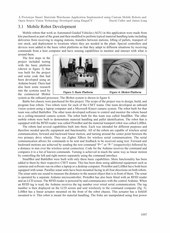
The first steps in the project included testing with the basic platform (shown in figure 3) that was built for the project and some code that had been developed using an Arduino board. There had also been some research into the systems used by the commercial IRobot system as the onboard processor. The IRobot system is shown in figure 4.
Battle bot chassis were purchased for this project. The scope of the project was to design, build, and program four robots. Two robots were for each of the CSET teams. One team developed an onboard vision system using a laptop computer and a Microsoft Kinect camera system. The robot built for that team was called BattleBot. The other team developed software to control and monitor the robots based on a ceiling-mounted camera system. The robot built for this team was called SmallBot. The other mobile robots were built to demonstrate material handling and pallet identification. The robot that is equipped with the RFID reader was called ProtoBot and the material transport robot was called LiftBot.
The robots had several capabilities built into them. Each was intended for different purposes and therefore needed specific equipment and functionality. All of the robots are capable of wireless serial communication, forward and backward linear motion, and turning around the center point between the two primary drive wheels. They use Zigbee XBees for wireless serial communication. The serial communication allows for commands to be sent and feedback to be received using text. Forward and backward motions are achieved by sending the text command “P+” or “P-” (respectively) followed by a distance in mm over the wireless serial connection. Code for the Arduino receives the command and compares it to a list of known commands. Turning is achieved in much the same way as linear motion by controlling the left and right motors separately using the command interface.
SmallBot and BattleBot were built with only these basic capabilities. More functionality has been added to them by their respective CSET teams. This has been done using additional equipment such as cameras and software run on either a laptop or a desktop computer. ProtoBot and LiftBot have both been equipped with sonar. Parallax sonar units have been mounted facing in all four directions on both robots. The sonar units use sound to measure the distance to the nearest object that is in front of them. The sonar is operated by a separate Arduino microcontroller. ProtoBot has also been fitted with an RFID reader and an LCD screen. The RFID reader is powered by and communicates with the control Arduino. When an RFID tag is read, the Arduino receives the tag number over wired serial communication. The tag number is then displayed on the LCD screen and sent wirelessly to the command computer (fig. 5). LiftBot has a linear actuator mounted on the front of the robot chassis. This actuator has a forklift mounted to it. This robot is meant for material handling. The forks are manipulated using four power
Figure 3: Basic Platform Figure 4: IRobot Platform
A Prototype Smart Materials Warehouse Application Implemented using Custom Mobile Robots andOpen Source Vision Technology Developed using EmguCV David Culler and James Long
1097

relays to control the polarity across the motor leads. The relays are controlled by the primary Arduino using the commands “LU” and “LD” to move the forklift up and down (for a number of seconds).
The frame and drive train were built slightly different for the robots. All of the robots are using 4 inch (in.) diameter drive wheels. SmallBot and ProtoBot are both two wheel drive with a caster for support in the back. ProtoBot uses hard plastic wheels that are directly connected to the output shafts on the motor. The wheels are attached using a set screw. SmallBot uses rubber wheels that are connected to the motors through a gear and chain transmission. This transmission is identical to what is used for the battle bot chassis except that the battle bot chassis has four motors and the front and back motors on each side are connected by an additional chain. Figure 6 shows the completed platform and Figure 7 the Graphical User Interface developed for the LiftBot configuration.
Figure 5: Schematic for RFID Reader Interface and Digital Readout
Figure 6: Mounting of Components on BattleBot Chassis
A Prototype Smart Materials Warehouse Application Implemented using Custom Mobile Robots andOpen Source Vision Technology Developed using EmguCV David Culler and James Long
1098

Many of the principles and concepts used for the mobile robots are very different from what would be used for a robot with a fixed base. Because the robot can only move on the floor, the robots location only needs to be determined in terms of X and Y position. The existing robots could also be interfaced with other robots such as articulated arms. In this way they could be used as part of a fully automated manufacturing demonstration. Some additional capabilities could be built on to these robots to allow them greater mobility. More functionality could be added to the Arduino to allow for multiple commands to be received in one transmission. The robot would then be able to execute the commands one at a time. Communication routines could also be added to allow for control of multiple robots simultaneously.
3.2 Kinect Driven Autonomous Robot for Obstacle Detection The Kinect Driven Autonomous Robot (K-DAR) is intended for use in a manufacturing
environment. Some modern factory robots are "autonomous" within the strict confines of their direct environment. When in such an environment, removing direct human interaction becomes beneficial. Without people on the manufacturing floors the robots will be able to work together seamlessly to deliver parts between stations. Costs could also be reduced because there would be a reliable and adaptable tool on the floor to take the place of traditional moving equipment. Another important benefit this type of robot is to promote safety.
The following section describes the functionality built into the system. They include: Path-Finding, Object Avoidance, and Computer-User Interaction:
1. Path Finding was incorporated to record distance travelled, command the robot to travel from one point to another, create a path in Cartesian points that are converted to polar coordinates to drive the robot without further user interaction, complex navigation (maze), and recalculate a path when an obstacle is encountered.
2. Object avoidance was implemented using the Kinect camera system and software routines for stereographic vision object detection, static and moving object avoidance, utilize user input avoidance strategies (wait, move around).
3. Computer – User interactions included controlled speed/acceleration, direction/turning, input points using coordinates, user stored paths.
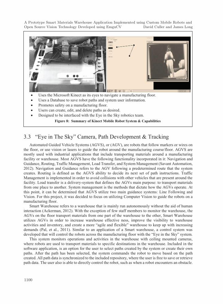
In addition many types of editing and path management functionality was implemented and a standard windows type user interface so that new users could easily adapt to robot operation. A database was also added for data and path management. The interface was developed using C# standard libraries and the .NET framework, an open source communication manager, and the Microsoft Kinect Software Development Kit. The robot and user interface for the Kinect system are shown below in Figure 8.
Figure 7: User Interface Created for Robot Operation
A Prototype Smart Materials Warehouse Application Implemented using Custom Mobile Robots andOpen Source Vision Technology Developed using EmguCV David Culler and James Long
1099
3.3 “Eye in The Sky” Camera, Path Development & Tracking Automated Guided Vehicle Systems (AGVS), or (AGV), are robots that follow markers or wires on
the floor, or use vision or lasers to guide the robot around the manufacturing course/floor. AGVS are mostly used with industrial applications that include transporting materials around a manufacturing facility or warehouse. Most AGVS have the following functionality incorporated in it: Navigation and Guidance, Routing, Traffic Management, Load Transfer, and System Management (Savant Automation, 2012). Navigation and Guidance refers to the AGV following a predetermined route that the system creates. Routing is defined as the AGVS ability to decide its next set of path instructions. Traffic Management is implemented in order to avoid collisions with other vehicles that are present around the facility. Load transfer is a delivery-system that defines the AGVs main purpose: to transport materials from one place to another. System management is the methods that dictate how the AGVs operate. At this point, it can be determined that AGVS utilize two main guidance systems: Line Following and Vision. For this project, it was decided to focus on utilizing Computer Vision to guide the robots on a manufacturing floor.
Smart Warehouse refers to a warehouse that is mainly run autonomously without the aid of human interaction (Ackerman, 2012). With the exception of few staff members to monitor the warehouse, the AGVs on the floor transport materials from one part of the warehouse to the other, Smart Warehouse utilizes AGVs in order to increase warehouse effective ness, improve the visibility to warehouse activities and inventory, and create a more “agile and flexible” warehouse to keep up with increasing demands (Pal, et al., 2011). Similar to an application of a Smart warehouse, a control system was developed that will control the robots across the manufacturing floor with the “Eye in the Sky” system.
This system monitors operations and activities in the warehouse with ceiling mounted cameras, where robots are used to transport materials to specific destinations in the warehouse. Included in the software application, is an option for the user to select paths created by the system or create their own paths. After the path has been selected, the system commands the robot to move based on the path created. All path data is synchronized to the included repository, where the user is free to save or retrieve path data. The user also is able to directly control the robot, such as when a robot encounters an obstacle.
Uses the Microsoft Kinect as its eyes to navigate a manufacturing floor. Uses a Database to save robot paths and system user information. Promotes safety on a manufacturing floor. Users can create, edit, and delete paths as desired. Designed to be interfaced with the Eye in the Sky robotics team.
Figure 8: Summary of Kinect Mobile Robot System & Capabilities
A Prototype Smart Materials Warehouse Application Implemented using Custom Mobile Robots andOpen Source Vision Technology Developed using EmguCV David Culler and James Long
1100
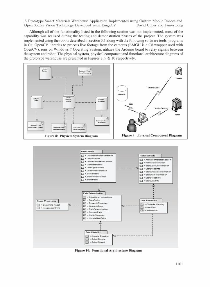
Although all of the functionality listed in the following section was not implemented, most of the capability was realized during the testing and demonstration phases of the project. The system was implemented using the robots described in section 3.1 along with the following software tools: programs in C#, OpenCV libraries to process live footage from the cameras (EMGU is a C# wrapper used with OpenCV), runs on Windows 7 Operating System, utilizes the Arduino board to relay signals between the system and robot. The physical system, physical component and functional architecture diagrams of the prototype warehouse are presented in Figures 8, 9 & 10 respectively.
Figure 10: Functional Architecture Diagram
Figure 8: Physical System Diagram
Figure 9: Physical Component Diagram
A Prototype Smart Materials Warehouse Application Implemented using Custom Mobile Robots andOpen Source Vision Technology Developed using EmguCV David Culler and James Long
1101
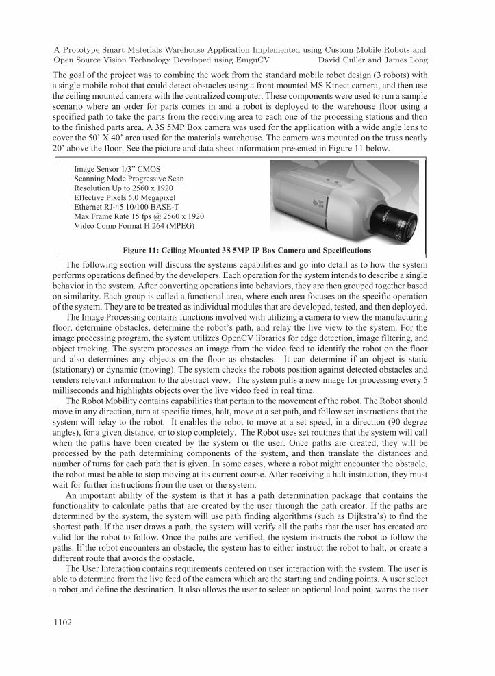
The goal of the project was to combine the work from the standard mobile robot design (3 robots) with a single mobile robot that could detect obstacles using a front mounted MS Kinect camera, and then use the ceiling mounted camera with the centralized computer. These components were used to run a sample scenario where an order for parts comes in and a robot is deployed to the warehouse floor using a specified path to take the parts from the receiving area to each one of the processing stations and then to the finished parts area. A 3S 5MP Box camera was used for the application with a wide angle lens to cover the 50’ X 40’ area used for the materials warehouse. The camera was mounted on the truss nearly 20’ above the floor. See the picture and data sheet information presented in Figure 11 below.
The following section will discuss the systems capabilities and go into detail as to how the system performs operations defined by the developers. Each operation for the system intends to describe a single behavior in the system. After converting operations into behaviors, they are then grouped together based on similarity. Each group is called a functional area, where each area focuses on the specific operation of the system. They are to be treated as individual modules that are developed, tested, and then deployed.
The Image Processing contains functions involved with utilizing a camera to view the manufacturing floor, determine obstacles, determine the robot’s path, and relay the live view to the system. For the image processing program, the system utilizes OpenCV libraries for edge detection, image filtering, and object tracking. The system processes an image from the video feed to identify the robot on the floor and also determines any objects on the floor as obstacles. It can determine if an object is static (stationary) or dynamic (moving). The system checks the robots position against detected obstacles and renders relevant information to the abstract view. The system pulls a new image for processing every 5 milliseconds and highlights objects over the live video feed in real time.
The Robot Mobility contains capabilities that pertain to the movement of the robot. The Robot should move in any direction, turn at specific times, halt, move at a set path, and follow set instructions that the system will relay to the robot. It enables the robot to move at a set speed, in a direction (90 degree angles), for a given distance, or to stop completely. The Robot uses set routines that the system will call when the paths have been created by the system or the user. Once paths are created, they will be processed by the path determining components of the system, and then translate the distances and number of turns for each path that is given. In some cases, where a robot might encounter the obstacle, the robot must be able to stop moving at its current course. After receiving a halt instruction, they must wait for further instructions from the user or the system.
An important ability of the system is that it has a path determination package that contains the functionality to calculate paths that are created by the user through the path creator. If the paths are determined by the system, the system will use path finding algorithms (such as Dijkstra’s) to find the shortest path. If the user draws a path, the system will verify all the paths that the user has created are valid for the robot to follow. Once the paths are verified, the system instructs the robot to follow the paths. If the robot encounters an obstacle, the system has to either instruct the robot to halt, or create a different route that avoids the obstacle.
The User Interaction contains requirements centered on user interaction with the system. The user is able to determine from the live feed of the camera which are the starting and ending points. A user select a robot and define the destination. It also allows the user to select an optional load point, warns the user
Figure 11: Ceiling Mounted 3S 5MP IP Box Camera and Specifications
Image Sensor 1/3” CMOS Scanning Mode Progressive Scan Resolution Up to 2560 x 1920 Effective Pixels 5.0 Megapixel Ethernet RJ-45 10/100 BASE-T Max Frame Rate 15 fps @ 2560 x 1920 Video Comp Format H.264 (MPEG)
A Prototype Smart Materials Warehouse Application Implemented using Custom Mobile Robots andOpen Source Vision Technology Developed using EmguCV David Culler and James Long
1102

when a dynamic obstacle is encountered, set the time that the robot remains at the destination, stop the robot at any time, queue up paths from the selected layout, or load up a stored path. User interaction can be depicted in many ways for most software applications. In this case, the user interactions are limited to how the user can manipulate the system. The user, first, will have to log-into the system so they can have access to all the functionality of the “Eye in the Sky” system. The user can define both loading and destination points for the robot to follow. The user can define paths manually via the included path creator if necessary. The user can control the robot via robot control system if they need to halt a robot, or need to move it. Through the Path Creator, users create paths based on a picture of the live footage from the ceiling mounted camera. With this path creator, users can draw paths for the robot to travel on. The user can draw connecting 90 degree lines based on a frame of the image from the camera. When the user draws the first line, it will have nodes that can be named and the start/end nodes can be set once each line is created. Nodes where the robot will stop on the way to the destination can be selected. The results are then stored to the database, where they can then be edited or reloaded at a later time.
Figure 12 below is a picture of the mock warehouse that was used for the use case stories below. The picture to the right depicts the image from the overhead camera as it appears in the user interface (Figure 13) including robot docking stations, where the robots are parked here when they are not being actively used by the system. The receiving dock station is where materials are received and placed for
the robots. The storage is where all materials are inventoried until they are to be used. The processing area is a general section where the robots will transport the raw materials to be pre-cut. The staging stations are areas where the robots take processed materials to be inspected by engineering staffs.
This use case survey will describe a normal session on a manufacturing floor, where materials from the loading docks are then stored, processed, prepared, or moved to be specific areas. This following story describes a manufacturing engineer, the shop supervisor, receiving some packaged materials that need to be processed and then transported to the staging areas. The shop supervisor receives a message from his superiors that the company has received material. They want him to process the incoming materials at the saw machine, where it is handled by on-site manufacturing engineers. After being processed by the engineers, the shop supervisor will then need to move the processed materials to the staging area where they are inspected by the inspection team before further use. With that in mind, the shop supervisor opens the Eye in the Sky application, logs into the application, and then checks to see which of the docked robots are inactive. The robot is commanded to move from the docking station to the materials docking station. The robot will then proceed to move the materials from the docking station to the processing station where engineers can take over. After the materials have been processed, the shop supervisor commands the robot to move the materials from the processing area to the staging stations, where it is loaded onto the stage and inspected. When completed, the robot returns to the docking station and waits for further commands.
Figure 12: Mock Warehouse Figure 13: User Interface with Video Feed
A Prototype Smart Materials Warehouse Application Implemented using Custom Mobile Robots andOpen Source Vision Technology Developed using EmguCV David Culler and James Long
1103

The Path Determination user case survey describes a scenario where the system will generate paths for the robot to follow. If the user finds the determined paths satisfactory, then the user can select that path, or the user can draw paths on the image so the robot can follow the paths that the user has drawn out. The shop supervisor receives an order from his superiors that requires him to move materials across the manufacturing floor. After the shop supervisor has received materials from the docking station, he then sets the station coordinate points and tasks that the robot needs to complete. The system then automatically generates paths for the robot to follow. After the system has calculated the paths, it will then display the paths for the shop supervisor to decide. The shop supervisor doesn’t like any of the paths that the system has created, so he decided to draw out the paths on the program. After drawing out the paths for the robot to follow, he starts the task up, and the robots now follow the new path that the shop supervisor has drawn out.
The Obstacles Handling user story will describe a scenario where the robot encounters an obstacle in its path as it is on its way to deliver the raw materials to the destination. The system will utilize the cameras mounted on the ceiling to see if any obstacles have moved from the start of the process. If the system detects a new obstacle, it will either re-route the robot to a new path, or halt and contact the user for an advisory action. In the case of the advisory action, the system will then contact the user that the system is unable to re-route the robot, and requires an advisory action to proceed. The shop supervisor notices from the cameras that one of the engineers is blocking the robot’s path. The robot will stop, and the system will display a warning to the program. The shop supervisor notices this warning and recognizes the engineer who is blocking the robot’s path. The shop supervisor will then call the engineer and tell him to move out of the robot’s path. Once the engineer has moved, the system will detect that there are no more obstacles that are encountered in the path. The system will then command the robot to proceed to drop off the raw materials to the robot’s destination. The shop supervisor can resume doing his own work as the robot navigates the floor unhindered. Sample code developed in EmguCV is shown here in Figure 14.
4 Conclusions and Future Work The smart warehouse project reached many of the expected results. The application allows the user
to draw paths from the path creator, in which it can be then stored to the database so it can be accessed later on. The Eye in the Sky application utilizes a ceiling mounted camera to track the robot on the floor. The robot is tracked as a rectangle in the abstract view of the application. Through the application, once the paths have been drawn, the user can then select to load it up and then draw it into the path abstract view. From there, the user can then select a start node, a load node, then a destination node for the robot to follow. This creates a path, in which the user can then select to add it to a path queue, or just run it by pressing the Start button in the application. The robot would then follow the path, reach the destination, and then return to the start point to wait for instructions (or proceed in the next part of the path from the path queue).
Figure 14: Open Source Eye in the Sky Code
A Prototype Smart Materials Warehouse Application Implemented using Custom Mobile Robots andOpen Source Vision Technology Developed using EmguCV David Culler and James Long
1104
The equipment and software that has been developed for this project could be utilized for many future projects. The vision systems could be refined to the level that the robots could be guided to specific storage locations and retrieve and store materials. The information from the sonar units could be utilized for more accurate robot positioning when the robot is in close proximity to objects of known location. Other items that could be used as next steps in this project include improve image detection, add complexity to how the robot is tracked, add to the types of obstacles that can be detected, allow for higher resolutions, multiple robots running simultaneously, incorporate multiple cameras.
The existing robots could also be interfaced with other robots such as articulated arms. In this way they could be used as part of a completely automated manufacturing demonstration. Additional capabilities could be added to these robots to allow them greater mobility. More functionality could be added to the Arduino to allow for multiple commands to be received in one transmission. The robot could then execute the commands one at a time. Additional communication routines could be used to allow for control of multiple robots simultaneously.
These types of systems could eventually be used for military applications such as search and rescue, warehouse management, munitions management, arming and disarming of military vehicles, and in medical facilities for deliveries. Many of these tasks are simple enough that the robot could handle the entire task, and some task could be assisted by robot for improved safety and reduced cost.
5 Acknowledgements The students of Manufacturing and Mechanical Engineering and Technology and the students of
Computer Software Engineering Technology at the Oregon Institute of Technology were key contributors to the material presented in this paper. Also thanks to the work of John Anderson who began this work in 2008-2009 before retiring in 2012. Graduate students Noah Anderson, Matthew Floyd and HoeJin Kim were instrumental in keeping this project moving forward.
References Arduino. (2012). Arduino board mega 2560. Retrieved May 15, 2012, from Arduino Products:
http://arduino.cc/en/Main/ArduinoBoardMega2560 Aryal, S. (2012). Integrating Camera Recognition and RFID System for Assets Tracking And Warehouse
Management. Thesis, Central Ostrobothnia University of Applied Sciences, Industrial Management, Ylivieska.
Berman, S., Schechtman, E., & Edan, Y. (2008). Evaluation of automatic guided vehicle systems. Robotics and Computer Aided Manufacturing, 2(9), 1-7.
Borenstein, J., Everett, H., & Feng, L. (1996). Where am I? Sensors and Methods for Mobile Robot Positioning. Ann Arbor: University of Michigan.
Cao, Y., Fukunaga, A., & Kahng, A. (1997). Cooperative mobile robotics: antecedents. Autonomous Robots 1997;4:1–23., 4(1), 1-23.
Cesetti, A., Frontoni, E., Mancini, A., Zingaretti, P., & Longhi, S. (2010). A Vision-Based Guidance System for UAV Navigation and Safe Landing using Natural landmarks. J Intell Robot Syst., 57, 233-257.
Isaksson, A., & Drath, R. (2016, April 6). ABB Group. Retrieved from CPS Conference Presentations: http://download.steinbeis-europa.de/2013-10-29-30_CPS/30102013-cps-isaksson-abb.pdf
Jang, O. J., Lee, O. S., & Moo, Y. B. (2009). Bridge Inspection Robot System with Machine Vision. Automation in Construction, 18, 929-941.
A Prototype Smart Materials Warehouse Application Implemented using Custom Mobile Robots andOpen Source Vision Technology Developed using EmguCV David Culler and James Long
1105

Kobilarov, M., & Sukhatme, G. (2006). People tracking and following with mobile robot using an omnidirectional camera and a laser. Proceedings of the 2006 IEEE International Conference on Robotics and Automation, (pp. 557-562). Orlando, FL.
Okuno, Y. T. (2008). A robot vision system for collision avoidance using a bio-inspired algorithm. Lect. Notes Comput. Sci. 4985, 107-116.
Peters, B., Smith, J., & Venkatesh, S. (1996). A control classification of automated guided vehicle systems. Int J Ind Eng, 3(1), 29-39.
Reveliotis, S. (2000). Conflict resolution in AGV systems. IIE Trans 2000;32:647–59, 32, 647-659. Saunders, C., Sterritt, R., & Wilkie, G. (2016, February 14). The Utility of Robot Sensory Devices in a
Collaborative Autonomic Environment. Retrieved from University of Ulster: http://uir.ulster.ac.uk/30789/1/CatherineSaunders-TheUtilityofRobotSensoryDevicesInACollaborativeAutonomicEnvironment(PhDstreamEASe2014).pdf
Sentry, T. (2016, February 16). Retrieved from Sentry Technology Corporation: www.sentrytechnology.com/travelingproducts/sentryvisionsmarttrack.html#maindivider
Smith, A., Balakrishnan, H., Goraczko, M., & Priyantha, N. (2004). Tracking Moving Devices with the Cricket Location System. MobiSYS.
Wenjie, Y., Weber, C., & Wermter, S. (2011). A hybrid probabilistic neural model for person tracking based on a ceiling-mounted camera. Journal of Ambient Intelligence and Smart Environments, 3, 237–252.
A Prototype Smart Materials Warehouse Application Implemented using Custom Mobile Robots andOpen Source Vision Technology Developed using EmguCV David Culler and James Long
1106