A Prototype Attitude Determination System for High Altitude Research Balloons Erin Doody, Fernando...
55
A Prototype Attitude Determination System for High Altitude Research Balloons Erin Doody, Fernando Esteves, Devon Gonteski, Michael Lamos, Jason Quisberth, Peter Schramm, Raissa Silva, Gary Uritskiy, Patricia Yoritomo Catholic University of America
-
Upload
phoenix-culpepper -
Category
Documents
-
view
218 -
download
1
Transcript of A Prototype Attitude Determination System for High Altitude Research Balloons Erin Doody, Fernando...

A Prototype Attitude Determination System for High
Altitude Research Balloons
Erin Doody, Fernando Esteves, Devon Gonteski, Michael Lamos, Jason Quisberth, Peter Schramm, Raissa Silva, Gary Uritskiy, Patricia Yoritomo
Catholic University of America

Mission Overview
*

Table of Contents• Mission Overview
o Components
o Theory and Concepts
o Expected Results
• System Overview
o Block Diagrams
o Mass Budget
• Subsystem Design
o Star Camera
o Flight Computer
o Pressure Vessel
o Electrical Box
o Gyros
• Prototyping Plan
o Assembly and Testing
• Management Plan
o Schedule
o Budget
o Task Distribution
o Contact Matrix

Mission OverviewOverall goal:
Design, fabricate, test, and launch a system that collects data
• 20kg payload
• Measure altitude to arc-second precision
• Use of commercially available and low-cost components
• Meets Columbia Scientific Balloon Facility (CSBF) requirementso Meets Undergraduate Student Instrument Project (USIP)

Main Components
• Daytime-Capable Star Camera
• Gyroscopeso Tilt Sensors
• Flight Computero Magnetometero Clinometero Thermometer
• Pressure Vessel
• Box

Theory & Concepts
• Electrical engineering, Mechanical engineering, and applied physics ideas and concepts will be used to order to construct, build, test, and fly payloado heat transfero signal processing and filteringo thermodynamics
• Knowledge of computer programming languages such as python will be used in order to operate the electronic components.
• Similar projects are seen on the HASP carrier by NASA BPO and LaSPACEo Successful flights and good data are signs that this project
is feasible within the timeline given

Expected Results
To develop a low-cost, low-mass system for real-time attitude determination
• Using of individual sensors including a daytime-capable digital star camera, MEMS gryoscopes, magnetometers, and tilt sensors (clinometers).
• The fast, relative sensors (gyroscopes) that are continuously updated by the slower, absolute sensors (star camera, magnetometers).
The integration of the gyro output will demonstrate real-time attitude determination to arc-second or better precision.

System Overview
*

System Level Block Diagram
*
AAS – Absolute Attitude SensingCCM – Climate Control and MonitorMP – Mounting PlatePV – Pressure VesselRAS – Relative Attitude SensingSP – Signal ProcessingUB – Unpressurized BoxVRB – Voltage Regulator Board

System Concept of Operations
*
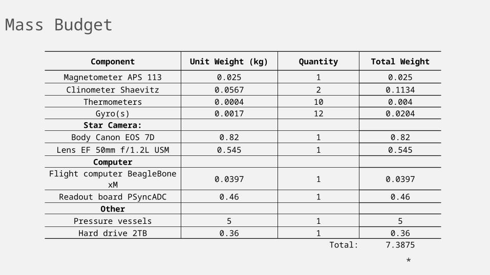
Mass Budget
*
Component Unit Weight (kg) Quantity Total Weight
Magnetometer APS 113 0.025 1 0.025
Clinometer Shaevitz 0.0567 2 0.1134
Thermometers 0.0004 10 0.004Gyro(s) 0.0017 12 0.0204
Star Camera:
Body Canon EOS 7D 0.82 1 0.82
Lens EF 50mm f/1.2L USM 0.545 1 0.545
Computer
Flight computer BeagleBone xM 0.0397 1 0.0397
Readout board PSyncADC 0.46 1 0.46
Other
Pressure vessels 5 1 5
Hard drive 2TB 0.36 1 0.36
Total: 7.3875

Subsystem Design
*

Star Camera DesignLens
*

Star Camera Lens Section
• This system is design with the intent to to capture images of stars in both the day and night during flight
• One of the requirements for the lens is that it must capture a minimum of 4 stars in the pipeline.
• By choosing a lens with a greater area we see an increase in performance by a factor of 1.36.
• Another advantage of the smaller f-stop lens is the size of the filter, 72mm vs. 58mm. The larger diameter lens provides a larger area and gives us a larger area of usable frame.
• Even though the f/1.2 lens is heavier (545g vs. 290g) the HASP payload bay that we have acquired is 20Kg, well within our current estimate of 3.54Kg.
*
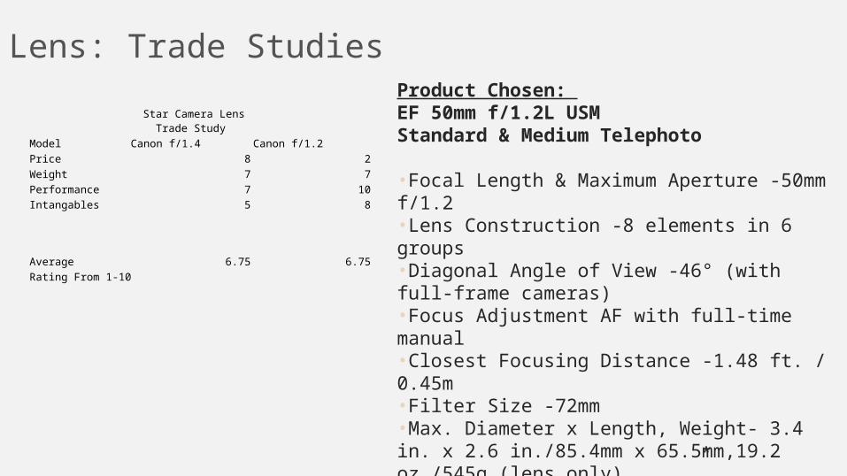
Lens: Trade Studies
*
Product Chosen: EF 50mm f/1.2L USMStandard & Medium Telephoto
•Focal Length & Maximum Aperture -50mm f/1.2•Lens Construction -8 elements in 6 groups•Diagonal Angle of View -46° (with full-frame cameras)•Focus Adjustment AF with full-time manual•Closest Focusing Distance -1.48 ft. / 0.45m•Filter Size -72mm•Max. Diameter x Length, Weight- 3.4 in. x 2.6 in./85.4mm x 65.5mm,19.2 oz./545g (lens only)
Star Camera Lens Trade Study
Model Canon f/1.4 Canon f/1.2Price 8 2Weight 7 7Performance 7 10Intangables 5 8
Average 6.75 6.75
Rating From 1-10

Star Camera DesignCamera Body
*

Camera Body Design Section
• The camera body will be connected to the computer through the means of a USB 2.0 cable.
• The software that will facilitate the communication between the flight computer is called gphoto2 and it will give use the ability to cycle shutter speed in flight
• The photos that will be take will be sent to the external hardrive.
• The reason for choosing the Canon 7D was that it is one of the only camera that is compatible with the gphoto2 software. – This limited the cameras that we could research thus
almost forcing us to choose the 7D.
*

Camera Body: Trade Study
*
Product Chosen:
Star Camera Body Trade Study
Model Canon 7D Canon 70DPrice 7 9Weight 7 7Performance 9 9Intangables 10 0
Average 8.25 6.25
Rating From 1-10

AAS: Risk Matrix
*
AAS.RSK.1: Mission objectives aren't met if the Star Camera overheats.AAS.RSK.2: Mission objectives are affected if the Star Camera parameters had not been set right.AAS.RSK.3: Mission objectives aren't met if the Camera fails to communicate with the flight computer.AAS.RSK.4: Mission objectives are affected if the camera lens becomes obstructed

*
Flight Computer Design

Flight Computer Design Section• The flight computer will be responsible for the data acquisition and
signal processing. It should have a good processing potential, enough I/O ports to connect all devices, compact size and be robust to different environments.
• The first option we consider for the flight computer was a ASUS laptop. It had all the processing potential we need and I/O ports. However, it had some disadvantages such as high price, big size, power consuming and produces too much heat.
• Single board computers are a very compact and cheap option that have also a great processing potential. The BeagleBoard-xM (the flight computer selected) have all the capacities we need for a very good price. It has 512 MB DDR memory, 1 GHz ARM Cortex-A8 processor, provides 4 USB ports and runs differents versions of linux.
*

Flight Computer: Trade Studies
*
• Show rationale for you choices in components. You basically weigh your options against your requirements and what each component can offer. Don’t forget things like: availability, cost, and prior knowledge. I recommend an online search for examples if you are unsure, or contact me.
Flight Computer Trade Study
ASUS Laptop Raspberry Pi Beagle Bone Beagle Bone XmPrice 5 10 10 8Weight 5 10 10 10Performance 10 7 7 8Power Requirements 4 8 8 8Ease to program 10 7 8 7Serial Ports 9 5 7 10Low Level Peripherals 0 5 7 8Size 4 10 10 10Average 5.875 7.75 8.375 8.625
Rating From 1-10

Subsystem Design Section• This section is where you explain how each subsystem was
designed• Start with your organization chart with each of your
subsystems labeled• Discuss how you researched components that would meet
your requirements– Show trade studies if necessary, and if you show them,
be prepared to explain the scoring and categories• The most important part is explaining how you reached
your major design decisions in each subsystem• After explaining components, discuss any risks associated
with this subsystem
*

SP: Risk Matrix
*
SP.RSK.1: Mission objectives aren't met if the computer or the PSyncADC board overheats.SP.RSK.2: Mission objectives aren't met if the flight computer fails in communicating to the PSyncADC.SP.RSK.3: Mission objectives aren't met if the flight computer fails in processing sensor data.SP.RSK.4: Mission objectives will be affected if bad sensor data is not filtered.SP.RSK.5: Mission objectives will be affected if the hard drive gets damaged on landing.
Pressure Vessel and Electrical Box Design
*

Subsystem Overview – Block Diagram
• The pressure vessel will connect to the electrical box that will connect to the large payload (carrier)
*
Electrical Box
Pressure Vessel
Carrier
Pressure Vessel and Electrical Box

Pressure Vessel
• Top view
• Side view
*
Star Camera
Flight Computer
Hard drive
Pressure Vessel

Electrical Box
• Top View
• Side View
*
Gyro Board
P-Sync
Electrical Box

EPS: Trade Studies
*
• Show rationale for you choices in components. You basically weigh your options against your requirements and what each component can offer. Don’t forget things like: availability, cost, and prior knowledge. I recommend an online search for examples if you are unsure, or contact me.
µController XMega ATMega 32 L
Cost 8 10Availability 10 10
Clock Speed 10 5A/D Converters 9 5
Programming Language 8 8
Average: 9 7.6
• You should have completed a trade study for each block, but you only need to present the 2-3 most important.
• Numbers are relatively subjective, but 10 should represent a perfect fit, 5 will work, but is not desirable, and 0 does NOT meet expectations.
• The component with the highest average should drive your choice for design.
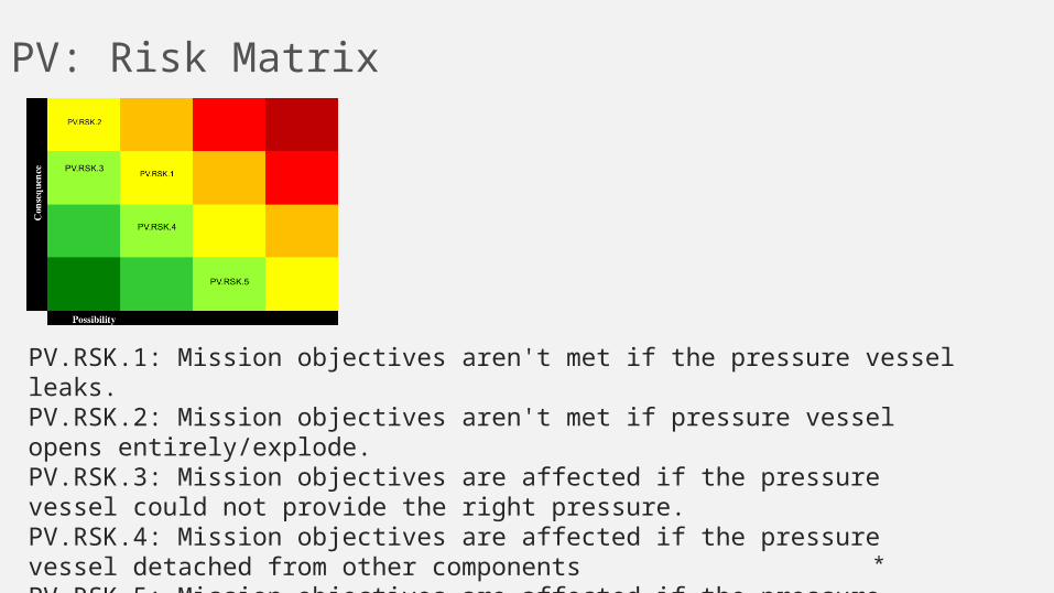
PV: Risk Matrix
*
PV.RSK.1: Mission objectives aren't met if the pressure vessel leaks.PV.RSK.2: Mission objectives aren't met if pressure vessel opens entirely/explode.PV.RSK.3: Mission objectives are affected if the pressure vessel could not provide the right pressure.PV.RSK.4: Mission objectives are affected if the pressure vessel detached from other componentsPV.RSK.5: Mission objectives are affected if the pressure vessel gets dented after landing.

CCM: Risk Matrix
*
CCM.RSK.1: Mission objectives are affected if heaters could not provide enough energy.CCM.RSK.2: Mission objectives are affected if thermometers fails to measure data correctly.CCM.RSK.3: Mission objectives are affected if heaters fails provide excessive energy;

VRB: Risk Matrix
*
VRB.RSK.1: Mission objectives aren't met if power supply cannot give enough power for the whole system.VRB.RSK.2: Mission objectives are affected if voltage regulation board fails in provide the correct voltage.VRB.RSK.3: Mission objectives aren't met if power supplies excessive amounts of current.

UB: Risk Matrix
*
PV.RSK.1: Mission objectives are affected if the unpressured box opens. PV.RSK.2: Mission objectives are affected if the unpressured box gets damage.

Gyro Selection
*

Gyro Overview – Block Diagram• Show your subsystems, now with more detail inside the boxes, and
the connections between them
*

Subsystem Design Section• This section is where you explain how each subsystem was
designed• Start with your organization chart with each of your
subsystems labeled• Discuss how you researched components that would meet
your requirements– Show trade studies if necessary, and if you show them,
be prepared to explain the scoring and categories• The most important part is explaining how you reached
your major design decisions in each subsystem• After explaining components, discuss any risks associated
with this subsystem
*

Gyro: Trade Studies
*
• Show rationale for you choices in components. You basically weigh your options against your requirements and what each component can offer. Don’t forget things like: availability, cost, and prior knowledge. I recommend an online search for examples if you are unsure, or contact me.
Gyro Trade Study
ITG3050 L3G4200D LPY403AL G200
Price 9 9 7 2
Range 10 10 10 10
Sensitivity 7 7 9 10
Noise Performance 4 4 9 10
Robustness 7 8 8 9
Average 7.5 7.5 8.75 8
Rating From 1-10
RAS: Risk Matrix
*
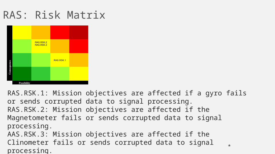
RAS.RSK.1: Mission objectives are affected if a gyro fails or sends corrupted data to signal processing.RAS.RSK.2: Mission objectives are affected if the Magnetometer fails or sends corrupted data to signal processing.AAS.RSK.3: Mission objectives are affected if the Clinometer fails or sends corrupted data to signal processing.

Prototype Assembly and Testing

Payload Prototype Assembly
• Construct metal box of identical dimensions to actual payload in order to test different part positioning
• Things to consider:– Positioning of all the parts relative to
each other– Vacuum chamber integrity– Insulation positioning

Sensor Testing• Once all the parts are hooked up together
and functioning, the multiple sensors present on the payload must be tested
• Things to consider– Sensor calibration– Sensor positioning within the payload– Reliability and accuracy of each sensor
Gyroscope Testing• After the completion of gyro fabrication, test
all gyros for proper functioning separately, then together as a system to guarantee that each board operates both by itself and in a system
• The accuracy and precision of the final gyroscope unit will be measured in a variety of tests

Temperature Regulation Requirements
• The payload electronic parts must remain in a certain temperature range to ensure proper function
• Temperature of the electric board(s) must be above 5°C but below 60°C
• To ensure this is met, the prototype of the payload must be put under extensive testing in extreme temperature conditions

Important Factors to consider
• Insulation – a insulating layer must be present to slow down heat dissipation from and into the vessel
• Ventilation – there must be circulation in the payload to ensure that the hottest parts do not overheat too quickly
• Thermostat heating – we plan on having an on-board thermostat with a heating element to heat up the system if the air inside goes too low

Testing the Prototype• There are two conditions under which the system
must be able to function– Room temperature: the heat dissipation from the
prototype vessel must be great enough so that it does not overheat, which means the excessive insulation must be avoided
– Upper stratosphere temperature (-5°C): the thermostat must be able to heat the system in the case in which the heat from the functioning parts is insufficient to maintain functional temperature
Final testing • Once the payload prototype is fully
assembled and all its parts are functional, it is important to leave the entire system running for several days at a time to identify any weak links in the physical and software design
• Running for long testing periods will reveal elusive coding bugs, design flaws, and system glitches that could potentially occur in flight

Project Management Plan


Schedule

Work Breakdown Structure
Pressure Vessel:● Trade studies● Designs and brainstorming● Sketch SolidWorks drawings● Electronic simulation and
testing in SolidWorks● Purchase materials● Preliminary fabrication
process● Thermal testing and
insulation design ● Test preliminary fabrication
design ● Final compiling with electrical
components
Unpressurized Box● Trade studies● Designs and brainstorming● Sketch SolidWorks drawings● Electronic simulation and testing
in SolidWorks● Purchase materials● Preliminary fabrication process● Thermal testing and insulation
design ● Test preliminary fabrication
design ● Final compiling with electrical
components

Work Breakdown Structure (con’t)
Absolute Attitude Sensing: • Trade studies
• Determine memory storage method
• Purchase lens
• Test equipment
• Install software
• Test software
• Write and test program for camera
• Program automated storage of photos
• Decide how the camera will be powered
Relative Attitude Sensing:
• Trade studies
• Purchase materials
• design circuit
• test design
• assembly
• mounting

Work Breakdown Structure (con’t)
Climate Control Monitor:
• Trade studies
• Purchase materials
• determine climate stabilization methods
• design
Signal Processing:
• Trade studies
• purchase materials
• set-up and test computer
• Test communications
• set up downlink communication
• Kalman filtering

Work Breakdown Structure (con’t)
Voltage Regulator Board:
• Trade studies
• design system
• purchase materials
• test
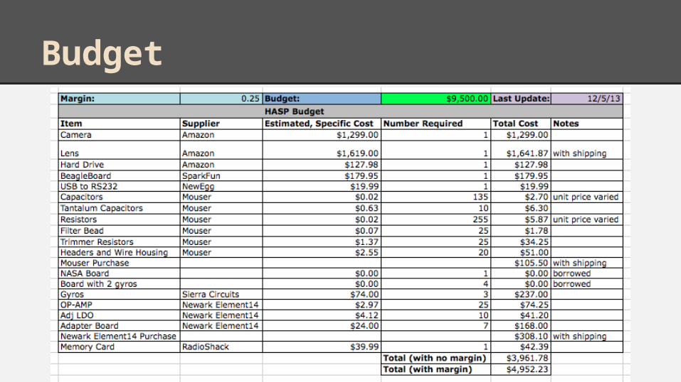
Budget

Team Contact Matrix