A project of Volunteers in Asia
100
A project of Volunteers in Asia Wls-.and Their Uses by : US Bureau of Naval Personnel Published by: Dover Publications 180 Varick Street New York, NY 10014 USA Paper copies are $ 2.75. Available from: Dover Publications 180 Varick Street New York, NY 10014 USA Reproduction of this microfiche document in any form is subject to the same resl:rlctions as those of the original document.
Transcript of A project of Volunteers in Asia

A project of Volunteers in Asia
Wls-.and Their Uses
by : US Bureau of Naval Personnel
Published by: Dover Publications 180 Varick Street New York, NY 10014 USA
Paper copies are $ 2.75.
Available from: Dover Publications 180 Varick Street New York, NY 10014 USA
Reproduction of this microfiche document in any form is subject to the same resl:rlctions as those of the original document.


DOVERBOOKSEXPLAINING SCIENCEANDMATHEMATICS
POPULAR SCIENTIFIC LECTURES OF HERMANN VON : TLLMHOLTZ, edited by Morris Kline. (20799-4) $2.00
THE DOMAIN OF NATURAL SCIENCE, E. W. Hobson. ,‘1966-6) $3.00
THE STRANGE STORY OF THE QUAIZXJM, Banesh T. HoPmann. (20518-5) $2.00
THE MOTH BOOK, W. J. Holland. (21948-g) $5.00
ELECTRONS, ATOMS, METALS AND ALLOYS, William Hume- Rothery. (61046-2) $3.50
SCIENCE AND MUSIC, Sir James Jeans. (.61964-8) $2.00
ARITHMETIC REFRESHER FOR PRACTICAL MEN. A. A. Klaf. (21241-6) $3.00
CALCULUS REFRESHER FOR TECHNICAL MEN, A. A. Klaf. (20370-O) $2.75
TRIGONOMETRY REFRESHER FOR TECHNICAL MEN, A. A. Klaf. (20371.9) $3.00
THE ATOMIC NUCLEUS, M. I. Korsunsky. (61052-7) $2.50
EXPERIMENTING WITH THE MICROSCOF. Dieter Kramer. (21847-3) $2.00
MAGNETISM: AN INTRODUCTORY SURVEY, E. W. Lee. (226654) $2.50
PIONEERS OF SCIENCE AND THE DEVELOPMENT OF THEIR SCIEN- TIFIC THEORIES, Sir Oliver Lodge. (20716-l) $2.50 .
A GUIDE TO MUSICAL ACOUSTICS, H. Lowery. (21628-4) $1.25
THE MUSHROOM HANDBOOK, Louis C. C. Krieger. (21861-9) $3.95
PRACTICAL STATISTICS, Russell Langley. (22729-4) $3.00
INTRODUCTION TO PHOTOGRAPHIC PRINCIPLES, Lewis Larmore, (21385-4) $2.00
CHANCE, LUCK AND STATISTICS: THE SCIENCE OF CHANCE, Horace C. Levinson. (21007-3) $2.50
(continued on back flap)

Do you have trouble with tools-find that they wear out too quickly, hnd that \ou can’t decide whit~h tools to buy or which tools to use for a specific job, lind that little things continually go wrong? The only way to learn to use tools, of course, is by using them, but first you have to know which tools to use and M.h!~.
This manual, originally prepared for the use of naval personnel, was de- signed to present the basic hand and power tools that the ordinary person is likely to use. Throu!gh a wealth of diagrams, clear explanations, safety ops sr4 operating instructions you will soon learn the basics of choosing ~~01s and using them as they were meant to be used. Searly every hand tool \ou are likrly to use around the house is described in the first chapter: h-nnnrrr, rvwnches. screwdrivers, wood saws, planes, wood chisels, metal chisels. dies, drills. files, hacksaws, punches, reamers, taps. clan~ps, rises. pliers. kniws. Chapter two covers the common power tools: drills, grinders. sindcrs. Chapter three covers measuring tools from rules and tapes to cali- pew micrometers and squares with detailed instructions on how to use each enc. Chapter four describes the common nails, screws. bolts, nuts, rivers 2nd other fasteners you are likely to use. Chapter five describes grinders and shows bon- to sharpen and care for screwdrivers, chisels, drills and snips. The final two chapters cover such miscellaneous tasks and tools as metal cutting operations, stripping insulated wire, and soldering techniques.
By the time you finish you should know the names, general uses and correct operation of all the basic tools, fasteners and measuring devices you are likely to need around the house. You should be able to select tools for a basic kit for doing simple home repairs. You should be confident in be- ginning to use tools for yourself to perform all those simple but necessary repair jobs that need to be done. Most important, however, you will begin to feel comfortable xound tools and begin to realize why they are truly man’s best friends.
Unabridged republication of the original (1971) edition of Rate Training Manual 10085-B. 329 figures. 15 tables. xii + 179pp. 6% x 9%.
22022-Z Paperbound
A DOVER EDITION DESiGSED FOR YEARS OF USE! We have made every effort to make this the best book possible. Our paper is opaque, with mmrmal show-through; it will not discolor or become brittle with age. Pages are sewn in signatures in the method traditionally used for the best books, and will not drop out, as often happens with paperbacks held together xvith glue. Books open Rat for easy reference. The binding will not crack or split. This is a permanent book.

(continued from front flap)
VISUU ILLUSIONS: THEIR CAUSES, CHARACTERISTICS AND Ap- PLICAT~NS, M. Luckiesh. (21530-X) $2.00
PHYSICS EXPERIMENTS FOR CHILDREN, Muriel Mandell. (22033-s) $1.25
THE FOURTH DIMENSION SIMPLY EXPLAINED, +Ienry P. Man- ning. (20711-o) $2.50
THE FRIENDLY STARS, Martha Evans Martin and Donald H. Menzel. (21099-s) $1.50
MATTER AND MOTION, James Clerk Maxwell. (60188-9) S2.00
SKYSHOOTING: HUNTING THE STARS WITH YOUR CAMERA, R. N. Mayall and M. W. Mayall. (21854-6) $2.75
THE NATURE OF LIGHT AND COLOUR IN THE OPEN AIR, M. Min- naert. (20196-l) $3.00
THE CONCEPT OF HEAT AND ITS WORKINGS SIMPLY EXPLAINED, Morton C. Mott-Smith. (20978-4) $2.00
TIE CONCEPT OF ENERGY SIMPLY EXPLAINED, Morton C. Mott- Smith. (21071-5) $2.00
PRINCIPLES OF MECHANICS SIMPLY EXPLAINED, Morton C. Mott-Smith. (21067-7) $2.00
CHEMI~TR~ EXPERIMENTS FOR CHILDREN, Virginia L. Mullin. (22031-l) $1.25
2hfus~c OF THE SPHERES: THE MATERIAL UNIVERSE FROM ATOM TO QUASAR, SIMPLY EXPLAINED, Guy Murchie. (21809-0, 21810-4) Two-volume set $5.00
THE ORIGIN OF LIFE, Alexandr I. OpaTin. (60213-3) $2.00
SPINNLNG TOPS AND GRYOSCOPIC MOTION, John Perry. (20416-2) $1.50
Paperbound unless otherwise indicated. Prices subject to change without notice. Available at your book dealer’s or write for free catalogues to Dept. Bex, Dover Publications. Inc., 180 Varick Street, New York, N. Y. 10014. Please indicate field of interest. Each year Dover publishes over 1.50 classical records and books in art, music, philosophy, literature, humor, science, languages, mathematics, and other areas. Manufacrured in the U.S.A.

------7
ureau of
ersonneij
DOVER PUBLICATIONS, INC.
NEW YORK

Pub!ished in Canada by General Publishing Com- pany, Ltd., 30 Lesmill Road, Don Mills. Toronto, Ontario.
Published in the United Kingdom by Constable and Cmpany, Ltd., 10 Orange Street, London WC 2.
This Dover edition, first published in 1973. is an unabridged aad unaltered republication of the work originally published by the United States Govern- ment Printing Office in 1971 as Rate Training Man- ual iXA’.‘PERS 10085-R.
Znternotional Standard -7ook Number: O-486-22022-2 Library of Congress Ca!?log Card Number: 72.93611
Manufactured in the United States of America Dover Publications, Inc.
180 Varick Street New York, N. Y. 10014

PREFACE The purpose of this manual is to provide na’rz: personnel with an in-
formative handbook. It contains data pertiwnt to a variety of tools and may be used as a supplement to other training manuals.
The satisfactory performaxe of nwdern technical equipment used by the Navy depends, to a great extent, upon adherence to approved maints- nance procedures and the proper use of the correct tools.
The objectives of this manual, then, are to aid in the maintenance ef- fort by
(a) providing descriptions, general uses, correct operation, and ap- proved maintenance procedures for those handtools and power tools commonly used in the Navy.
(b) indoctrinating all personuel engaged in maintenance work with the importance of good workmanship.
(c) preventing and minimizing personal injury and equipment damage by emphasizing good safety practices.
Upon completion of this manual, you should be able to identify tools and fastening devices by their correct names; cite the specific purposes and uses of each tool; describe the correct operation, care and maints- name required to keep the tools in proper operating condition; and finally, perform accurate measurements.
Chapter 1 describes impact tools (hammers, mallets, and sledges), hvisting and turning tools(wrenches and screwdrivers),woodcuttin (wood saws, planes, wood chisels), metal cuttin
tools ) g toyi-! dies,
drills, files, hacksaws, punches, reamers, taps , holdmg tools (clamps, pliers, and vises), miscellaneous tools (kuives, nZiZiiEal fingers, in- spection mirrors), safety equipment (gloves, goggles, hard hats), and safety rules.
Chapter2 describes pneumatic and electrically powered tools. Drills, sanders, grinders and scalers are some of the tools discussed.
Certain tools are especially useful for measuring purposes. For this reason, rules, tapes, calipers, micrometers and squares, together with techniques for using them are placed in Chapter 3.
Although fasteners are not properly classified as tools, they are used extensively with tools. Chapter 4 describes such fasteners as bolts, cotter pins, nails, nuts, rivets, screws, special speed fasteners (Dzus and Camloc types), and several methods for safetying some of these components.
Chapter 5 discusses abrasive wheels and methods for grinding and sharpening chisels, drills, punches, and snips.
Metal cutting operations using the chisel, drill, reamer and several types of thread cutters are described in Chauter 6.
The final chapter describes miscsllaue& tasks the student may en- counter. These include bending and flaring tubing. removing broken bolts, studs and taps, stripping insulated wire, and several soldering techniques and lubrication procedures.
As one of the Navy Training Manuals, this book was prepared by the Training Publications Division,Naval Personnel Program Support Activ- ity, Washington, D.C., for the Bureau of Naval Personnel.
Special assistance has been rendered by various Navy personnel spe- cially cognizant of the handtools and portable power tools used, and the work operations in which they are chiefly employed.

SUGGESTIONS FOR USING THIS RQOK
Many people do not know how to study. The following suggestions might improve your study habits and enable you to learn more from this book. s Set up a regular study plan. It will probably be easier for you to stick
to a schedule if you can plan to study at the same time each day. If possible, schedule your studying for a time of day when you will not have too many interruptions or distractions.
s Before you begin to study any part of the training manual intensively, become familiar with the entire book. Read the preface and the table of contents. Check through the index. Thumb through the book with-’ out any particular plan, looking at the illustrations and reading bits here and there as you see things that interest you.
s Look at the training manual in more detail,to see how it is organized. Look at the table of contents again. Then, chapter by chapter, read the introduction,the headings, and the subheadings. This will give you a pretty clear picture of the scope and content of the book. As you look through the book in this way, ask yourself some questions: What do I need to learn about this? What do I slready know about this? Row is this information related to information given in other chap- ters? How is this information related to the qualifications for ad- vancement in rating?
s When you have a general idea of what is in the training manual and how it is organized, fill in the details by intensive study. In each study period, try to cover a complete unit-it may be a chapter, a section of a chapter, or a subsection. The amount of material that you caa cover at one time will vary. If you know the subject well, or if the material is easy, you can cover qui’te a lot at one time. Diffi- cult or unfamiliar material will require more study time.
s In studying any one unit-chapter, section, or subsection-write down the questions that occur to you. Many people find it helpful to make a written outline of the unit as they study, or at least to write down the most important ideas.
l As you study, relate the information in the training manual to the knowledge you already have. When you read about a process, a skill, or a situation, try to see how this information ties in with your own past exwrience.
s When yea have finished studying a unit, take time out to see what you have learned. Look back over your notes and questions. Maybe .%me of your questions have been answered,hut perhaps you still have some that are not answered. Ask one of your senior petty officers or ship- mates for assistance. Without looking at the training manual, write down the main ideas that you have gotten from studying this unit. Don’t just quote the book. If you can’t give these ideas in your own words, the chances are that you have not really mastered the information.
l Think of YOUR future as you study Navy Training Manuals. You are working for advancement to third class or second class right now, but someday you will be working toward higher rates. Anything extra that you can learn now will help you both now and later.
ix

e If you desire information about a specific tool or operation, simply refer to the index at the alphabetical end of the book and then turn to the pages to which you are directed by that index.
Always keep in mind that a knowledge of the tools and their fqunda- mental uses is tbe preliminary step in mastering the basic handtool skills. The next step is careful practice until you have mastered the various skills involved. The end result must be that you become capa- ble of psi-forming required operations, and of meeting the standards es- tablished in your rating qualifications. To accomplish this final result, you must first STUDY the tools and skills; then, you must PRACTICE the skills; and finally, you must DEMONSTRATE the skills.
x


c TS
CHAPTER
1. Common Handtools . . . . . . . . . . . . ,
2. Common Power Tools . . . . . . . . . .
3. Measuring Tools and Techniques . . .
4. Fastening Components and Procedures .
5. Grinding Operations . . . . . . . . . . . .
6. Metal Cutting Operations . . . . . . . . .
7. Miscellaneous Tasks . . . , . . , . . . . . .
INDEX . . . . . . . . . . . . . . . . . . . . . . . . . . . . . .
. .
. .
.
. .
. .
. .
. .
. .
Page
1
61
78
. 112
. 126
. 141
. 159
176
xi

Illustrations indicated below are included through the courtesy of the designated companies and publishers. Permission to use these illustra- tions is gratefully acknowledged.
SOURCE
Buckingham Mfg. Co.
General Motors Corp.
Imperial Brass Mfg. Co.
Rockwell Mfg. Corp.
Ingersoll-Rand Corp.
Cleveland Twist Drill Co.
New York State Education Dept.
Eugene Dietzgen Co.
Delmar Publishers Inc.
xii
FIGURE --
6-26
l-7
6- 38 6-40 7.. 1 7-3
2-6 2-l 2-8 2-11
2-14 2- 16
1-41
1-21 1-22
3-12
4-5

CHAPTER 1
COMMON HANDTOOLS
Tools are designed to make a job easier and enable you to work more efficiently. Tools are a craftsman’s best friend. (A craftsman is a master of any one it a number of trades such as a machinist, carpenter, hull technician, builder, or steelworker.) If the tools are not used properly or cared for, their advantages will be lost. Without them a craftsman is as helpless as he would be without his eyes. In fact, he would be more helpless, for a blind mechanic or craftsman skilled in the use of good tools and having them available, can do more than the most expert mechanic without tools.
Regardless of the type of work to be done, a craftsman must have, choose, and use the cor- .:-wi toc!s in order to do his work quickly, ac- cwa:e!y, and safely. Without the proper tools and the knowledge of how to use them, he wastes rime, reduces his efficiency, and may even in- jure himself. This chapter expiafns the spe- cific purposes, correct use, and proper care of the more common tools you may encounter in your Navy GWF .:-.
THE ~~Z0.X ~.&Z;ABLE TCOLS W THE WOHf.2
What would you pay for THE MOST VALU- ABLE TOOLS iN THE WORLD? These tools can help you grip, grasp, push, twist and help you operate equipment. Furthermore, these re- markable tools can distinguish temperature variations and are sensitive to touch. It is im- possible to purchase such tools . . . they are “our HANDS.
These fabulous tools are subject to injury by being caught in machines, crushed by objects, or cut by a variety of sharp edged tools such as chisels, knives, or saws. Additionally, your hands can bs damaged by being burnt, frac- tured or sprained unless you are always alert.
V;ny? Because they cannot THINK for them- selves. PROTECT THEM. They are invalu- able. KEEP ALERT while you work. THINK as you work. THINK before you make adjustments to machinery. Has the electric power been
turned off? Are the required guards on the ma- chinery? Is the object on which you are going to work properly secured ad clam, ?LI?
Protect your hands from injure; ,?s direrted by the applicable safety instructi,lni. wtenever you use tools. You will be working under se- vere handicaps without the full ,:se of both hands. Make it a habit to FOLLOW ALL SAFETY RULES.
TEN COMMANDMENTS
Obey the ten commandments of safety: 1. LEARN the safe way to do your job be-
fore you start. 2. THINK safety, and ACT safety at all
times. 3. OBEY safety rules and regulations-they
are for your protection. 4. WEAR proper clothing and protective
equipment. 5. CONDUCT yourself properly at all
times-horseplay is prrhibited. 6. OPERATE only the equipment you are
authorized to use. 7. INSPECT tools and equipment for safe
condition before starting work. 8. ADVISE your superior promptly of any
unsafe conditions or practice. 9. REPORT any injury immediately to your
superior. 10. SUPPORT your safety program and take
an active part in safety meetings.
In addition to the above,there are other good tool habits which will help you perfor.m your work more efficiently as well as safely.
TOOL HABITS
“A place for everything and everything in its place” is just common sense. You can’t do an efficient, fast repair job if you have to stop and look around for each tool you need. The follow- ing rules, if followed,will make your job easier for you.
I

TOOLS AND THEIR USES
KEEP EACH TOOL IN ITS PROPER STOW- AGE PLACE.-A too! is useless if you cannot find it. If you return each tool to its proper place, you’ll know where it is the next time you need it.
KEEP YOUR TOOLS IN GOOD CONDITION.- Protect them from rust, nicks, burrs, and breakase.
KEEP YOUR TOOL ALLOWANCE COM- PLETE.-If you are issued a tool box (fig. l-l), each tool should be placed in it when not in use. If possible, the box should be locked and stored in a desi.mated area. Note: Never leave the handbox adrift where it could become a missile and cause injury to personnel. An inventory list retained in the box and checked after each job will help you keep track of your tools.
USE EACH TOOL ONLY ON THE JOB FOR WHICH IT WAS DESIGNED.-If you “se the wrong tool to make an adjustment, the results will probably be unsatisfactory. For exam$:e, if you use a socket wrench that’s a trifle too big, you’ll round off the corxzrs of the wrench or nut. If this rounded wrench or nut is not re- placed immediateiy the safety of your ship may be jeopardized in an emergency. Does this sound exaggerated? Remember . . . for want of a nail, a kingdom was lost.
KEEP YOUR TOOLS WITHIN EASY REACH AND WHERE THEY CANNOT FALL ON THE FLOOR OR MACHINERY.-Avoid placing tools anywhere above machinery or electrical appa- ratus. Serious damage wi!: result if the tool falls into the machinery after the equipment is energized.
56.37(448) Figure 1-l.-Standard Navy toolbox.
NEVER USE DAMAGED TOOLS,-A bat- tered screwdriver may slip and spoil the screw slot, damage other parts, or cause painful injury. A gage strained out of shape will result in inaccurate meascrements.
Remember, the efficiency of a craftsman and the tools he uses are determined to a great extent by the way he keeps his tools. Likewise, he is frequently judged by the manner in which he handles and cares for them. Anyone watch- ing a skilled craftsman at his work notices the care and precision with which h:, uses the tools of his trade.
The care of hand tr,, z+ould follow the same pattern as for p?“’ : i .Irticles; that is, always keep hand tools ‘, d freefrom dirt, grease, and foreign ma”, After use, return tools promptlyto their : (/,_ ’ piace in the tool- box. Improve your o’i. : .<iency by organizing your tools so that those used most frequently can be reached easily without digging through the entire contents of the box. Avoid accumu- lating unnecessary junk.
5.5(44B)A Figure l-Z.-Hammers, mallets and sledges.
2

Chapter l-COMMON HANDTOOLS
STRIKING TOOLS
Hammers. mallets, 2nd sledges are used to apply a striking force. The tool you Select (fig. l-2) will depend upon the intended application.
HAMMERS
A toolkit for nearly every rating in the Navy would not be completewithout at least one ham- mer. fn most cases, two or three are included since they are designated according to weight (without the handle) and style or shape. The shape (fig. l-2) will vary according to the in- tended work. The carpenter’s hammer is de- signed for one purpose while the machinist’s hammer has other primary functions.
Carpenter’s Hammer
The primary use of the carpenter’s hammer is to drive or draw (pull) nails. Note the names of the various parts of the hammer shown in figure l-2. The carpenter’s hammer has either a curved OP straight claw. The face may be either bell-faced or plain-faced, and the handle may be made of wood or steel. The carpenter’s hammer generally used in the Navy has a curved claw, bell face, and wooden handle.
Machinist’s Hammer
Machinist’s hammers a-e mostly used by people who work with metal ox- around machin- ery. These hammers are distinguished from carpenter hammers by a variable-shaped peen, rather than a claw, at the opposite end of the face (fig. l-2). The ball-pea hammer is prob- ably most familiar to you.
The ball-pee* hammer, as its name im- plies, has a ball which is smaller in diameter than the face. It is therefore useful for striking areas that are too small for the face to enter.
Ball-pee* hammers are made in different weights, usually 4, 6, 8, and 12 ounces and 1, 1 l/2, and 2 pounds. For most work a 1 l/2- pound and a 12-ounce hammer will suffice. However, a 4- or B-ounce hammer will often be used for light work such as tapping a punch to cut gaskets out of sheet gasket material.
Machinist’s hammers maybe further divided into hard-face and soft-face classifications. The hard-freed hamn& is made of forged tool steel while the soft-faced hammers have a head made from brass, lead, or a tightly rolled strip
of rawhide. Plastic-tipped hammers, or solid plastic with a lead core for added weight, are becoming increasingly popular.
Soft-faced hammers, (fig. l-2) should be used when there is danger of damaging the sur- face of the work, as when pounding on a ma- chined surface. Most soft-faced hammers have heads that can be replaced as the need arises. Lead-faced hammers, for instance, quickly be- come battered and must be replaced, but have the advantage of striking a solid, heavy nonre- bounding blow that is useful for such jobs as driving shafts into or out of tight holes. If a soft-faced hammer is not available, the surface to be hammered may be protected by covering it with a piece of soft brass, copper, or hard wood.
Using Hammers
Simple as the hammer is, there is 3 right and wrong way of using it. (See fig. l-3.) The most common fault is holding the handle too close to the head. This is known as choking the
5.5.1(44A) Figure 1-3.-Right and wrong way to use a
ball-pea hammer.
3
TOOLS AND THEIR USES
hammer, and reduces the force of the blow. It also makes it harder to bold the head in an up- right position. Except for light blows, hold the handle close to the end to increase the lever arm and produce a more effective blow. Hold the handle with the fingers underneath and the thumb along side or on top of the handle. The thumb should rest on the handle and never over- lap the fingers. Try to hit the object with the iti1 force of the hammer. Hold the hammer at such an angle that the face of the hammer and the surface of the object being hitwill be paral- lel. This distributes the force of the blow Over the fuil face and prevents damage to both the surfacebeing struckand theiace of thehammer.
MALLETS AND SLEDGES
The mallet is a short-handled tool used to drive wooden-handled chisels, gouges, wooden pins,or form or shape sheet metal where hard- faced hammers would mar or injure the finished wcrk. Mallet heads are made from a soft ma- terial, usually wood, rawhide, or rubber. For example, a rubber-faced mallet is used for knocking out dents in an automobile. It is cylindrically shaped with two flat driving faces that are reinforced with iron bands. (See fig. 1-2.) Never use a mallet to drive nails, screws, or any zabject that may cause damage to the face.
The sledge is a steel headed, heavy duty driving tool that can be used for a number of purposes. Short-handled sledges are used to drive bolts, driftpins, and large nails, and to strike cold chisels and small hand rock drills. Long-handled sledges are used to break rock and concrete, to drive spikes, bolts, or stakes, and to strike rock drills and chisels.
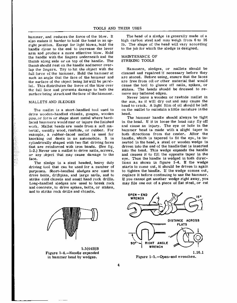
5.5(44B)B Figure 1-4.-Handle expanded
in hammer head by wedges.
The head of a sledge is generally made of a high carbon steel and may weigh from 6 to 16 lb. The shape of the head will vary according to the job for which the sledge is designed.
MAINTENANCE OF STRIKING TOOLS
Hammers, sledges, or mallets should be cleaned and repaired ii necessary before they are stored. Before using, ensure that the faces are free from oil or other material that would cause the tool to glance off nails, spikes, or stakes. The heads should be dressed to re- move any battered edges.
Never leave a wooden or rawhide mallet in the sun, as it will dry out and may cause the head to crack. A light film of oil should be left on the mallet to maintain a little moisture inthe head.
The hammer handle should always be tight in the head. If it is loose the head may fly off and cause an injury. The eye or hole in the hammer head is made with a slight taper in both directions from the center. After the handle, which is tapered to fit the eye, is in- serted in the head, a steel or wooden wedge is driven into the end of the handlethat is inserted into the head. This wedge expands the handle and causes it to fill the opposite taper in the eye. Thus the handle is wedged in both direc- tions as shown in figure l-4. If the wedge starts to come out, it should be driven in again to tighten the handle. If the wedge comes out, replace it before continuing to use the hammer. If you cannot get another wedge right away, you may file one out of a piece of flat steel, or cut
1.16.1 Figure l-5.-Open-end wrenches.
4

Chapter l-COMMON HANDTOOLS
one from a portion of the tang of a wornout file. The tang is the end of the file that iits into the handle.
SAFETY PRECAUTIONS
Hanmers are dangerous tools when used carelessly and without consideration. Practice will help you learn to use a hammer properly.
Some important things to remember when using a hammer or mallet follow:
6 Do not use a hammer handle for bumping parts in assembly, and never use it as a pry bar. Such abuses will cause the handle to split, and a split handle can produce bad cuts or pinches. When a handle splits or cracks, do not try to repair it by binding with string or wire. REPLACE IT.
l Make sure the handle fits tightly on the head.
l Do not strike a hardened steel surface with a steel hammer. Small pieces of steel may break oifand injure someone inthe eye or dam- age the work. However, it is permissible to strike a punch or chisel directly with the ball- peen hammer because the steel in the heads of punches and chisels is slightly softer than that of the hammerhead.
~ui3ta~G TOOLS (WRENCHES)
A wrench is a basic tool that is used to exert a twisting force on bolt heads, nuts, studs and pipes. The special wrenches designed to do certain jobs are, in most cases, variations of the basic wrenches that will be described in this section.
Some ratings will naturally have more use for wrenches in doing their jobs than other rat- ings; however, practically all ratings, including clerical, will have occasion, from time to time, to use : renches. lt is necessary, therefore, that all hands have a basic understanding of the description and uses of wrenches.
The best wrenches are made of chrome ~a- nadium steel. Wrenches made of this material are light in weight and almost unbreakable. This is an expensive material, however, so the most common wrenches found in the Navy are made of forged carbon steel or molybdenum steel. These latter materials make good wrenches, but they are generally built a little heavier and bulkier in order to achieve the same degree of strength as chrome vanadium steel.
The size of any wrench used on bolt-heads or nuts is determined by the size of the opening between the jaws of the wrench. The opening of a wrench is manufactured slightly larger than the bolt head or nut that it is designed to fit. Hex-nuts (six-sided) and other types of nut or bolt heads are measured across opposite flats (fig. l-5). A wrench that is designed to fit a 3/8-inch nut or bolt usually has a clearance of irom 5 to 8 thousandths of an inch. This clear- ance allows the wrench to slide on and off the nut or bolt with a minimum of “play.” If the wrench is too large, the points of the nut or bolt head will be rounded and destroyed.
There are many types of wrenches. Each type is designed for a specific use. Let’s dis- cuss some of them.
OPEN-END WRENCHES
Solid, nonadjustable wrenches with open- ings in one or both ends are called open-end wrenches. (See fig. l-5.) Usually they come in sets of from 6 to 10 wrenches with sizes rang- ing from 5/16 to 1 inch. Wrenches with small openings are usuaily shorter than wrenches with large openings. This proportions the lever advantage of the wrench to the bolt or stud and helps preventwrench breakage or damage to the boit or stud. One exception exists.
Aircraft today are built in a very compact manner; and generally, many of the hydraulic
l.l6(44B)A Figure 1-6.-Hydraulic wrenches.
5

TOOLS AND THEIR USES
1. WRENCH, WTH OPENING SLOPING TO THE LEFT, ABOUT TO BE PLACEDON NUT.
2. WRENCH POSITIONED AND READY TO TIGHTEN NUT. NOTE THAT SPACE FOR SWINGING THE WRENCH IS LIMITED.
3. WRENCH HAS BEEN MOVED.CLOCKWlSE TO TIGHTEN THZ NUT AND NO,” STRlKES THE CASTING WHICH PREVENTS FURTHER MOVEMENT.
4. WRENCH,SREMO”EDFROMN”TANDTURNEDCOUNTE~ CLOCKWlSE TO BE PLACED ON THE NEXT SET OF FLATS ON NUT. BUT CORNER OF CASTING PREVENTS WRENCH FROM FlTTlNG ONTO THE NUT.
5. WRENCH IS BEING FLOPPED OVER SO THAT WRENCH OPENING WlLL SLOPE TO THE RIGHT.
6. IN THlS FLOPPED POSITION, THE WRENCH WlLL FIT THE NEXT TWO FLATS ON THE NUT.
7. WRENCH NOW IS PULLED CLOCKWISE TO FURTHER TIGHTEN NUT UNTIL WRENCH AGAlN STRIKES CASTING. BY REPEATING THE FLOPPING PROCEDURE, THE NUT CAN BE TURNED UNTIL tT 15 TIGHT.
l.l6(44B)BX Figure l-I.--Use of open-end wrench.
6

Chapter l-COMMON HANDTOOLS
installations are in close spaces. During cer- tain phases of hydraulic maintenance it may be impossible to swing an ordinary wrench due to its length. Ordinary wrenches’%at are normally available increase in length as their size in- creases. Thus, when a large size wrench is needed, the length of the wrench sometimes prevents its use, due to the space available to swing the wrench. The Bonnsy wrench shown in figure l-6, is an open-end wrench that may be used to great advantage due to its thickness and short length. This wrench is normally pro- cured in the larger sizes, although it is avail- able in a range of sizes to fit all aircraft hy- draulic fittings.
Open-end wrenches may have their jaws parallel to the handle or at angles anywhere up to 90 degrees. The average angle is 15 degrees (fig. l-5). This angular displacement variation permits selection of a wrench suited for places where there is room to make only a part of a complete turn of a nut or bolt. U the wrench is turned over after the first swing, it will fit on the same flats and turn the nut farther. After two swings on the wrench, the nut is turned far enough so fhat a new set of flats are in position for the wrench as shown in figure l-7.
Handles are usually straight, but may be curved. Those with curved handles are called S-wrenches. Other open-end wrenches may have offset handles. This allows the head to reach nut or bolt heads that are sunk below the surface.
BOX WRENCHES
Box wi+nehes (fig. l-8) are safer than open- end wrenches since there isless likelihood they wili slip off the work. They completely sur- round 01‘ box a nut or bolt head.
The most frequently used box wrench has 12 points or not&es arranged in a circle in the head and can be used with a minimum swing angle of 30 degrees. Six and eight point wrenches are used for heavy, 12 for medium, and 16 for light duty only.
1.162 Figure l-8.- 12-point hx-end wrench.
One advantage of the 12 point construction is the thin wall. It is more suitable for turning nuts which are hard to get at with an open-end wrench. Another advantage is that the wrench will operate between obstructions where the space for handle swing is limited. A very short swing of the handle will turn the nut far enough to allow the wrench to be lifted and the next set of points fitted to the corners of the nut.
One disadvantage of the box-end wrench is the loss of time which occurs whenever a craftsman has to lift the wrench off and place it back onthe nut in another position in case there is insufficient clearance to spin the wrench in a full circle.
COMBINATION WRENCH
After a tight nut is broken loose, it can be unscrewed much more quickly with an open-end wrench than with a box-wrench. This is where a combioation box-open end wrench (fig. l-9) comes in handy. You can use the box-end for breaking nuts loose or for snugging them down, and the open-end for faster turning.
The box-end portion of the wrench can be designed with an offset in the handle. Notice in figure 1-9, how the 15-degree offset allows clearance over nearby parts.
The correct use of open-end and box-end wrenches ckn be summed up in a few simple roles, most important of which is to be sure that the wrench properly fits the nut or bolt head.
When you have to poll hard on the wrench, as in loosening a tight nut, make sure the wrench is seated squarely on the flats of the nut.
PULL on the wrench-DO NOT PUSH. Push- ing a wrench is a good way to skin your knuckles if the wrench slips or the nut breaks loose unexpectedly. If it is impossible to pull
1.16.3(448) Figure 1-9.-Combination wrench.
7

TOOLS AND THEIR USES
44.3(44B) Figure l- IO.-Socket set components.
Socket end Drive end
44.4 Figure I-Il.-12-point sockets.
the wrench, and you must push, do it with the palm of your hand and hold your palm open.
Only actual practice will tell you if you are using the right amount of force on the wrench.
The best way to tighten a nut is to turn it until the wrench has a firm, solid “feel.” This will turn the nut to proper tightness without strip- ping the threads or twisting off the bolt. This “feel” is developed by experience alone. Prac- tice until you have mastered the “feel.”
SOCKET WRENCH
The socket wrench is one of the most versa- tile wrenches in the toolbox. Basically, it con- sists of a handle and a socket type wrench which can be attached to the handle.
The “Spintite” wrench shown in figure l-10, is a special type of socket wrench. It has a hol- low shaft to accommodate a bolt protruding through a nut, has a hexagonal head, and is used like a screwdriver. It is supplied in small sizes only and is useful for assembly and elsc- trical work. when used for the latter purpose, it must have an insulated handle.
Acomplete socketwrench set consists of sev- eral types of handles along with bar extensions, adapters, and a variety of sockets (fig. l-10).
8

Chapter l-COMMON HANDTOOLS
Sockets
A socket (fig. l-11) has a square opening cut in one end to fit a square drive lug on a detach- able handle. In the other end of the socket is a &point or 12-point opening very much like the opening in the box end wrench. The 12-point socket needs to be swung only half as far as the 6-point socket before it has to be lifted and fitted on the nut for a new grip. It can there- fore be used in closer quarters where there is less room to move the handle. (A ratchet handle eliminates the necessity of lifting the socket and refitting it on the nut again and again.
Sockets are classified for size according to two factors. One is the size of the square open- ing, which fits on the square drive lug of the handle. This size is known as the drive size. The other isthe size of the opening in the oppo- site end, which fits the nut or bolt. The stand- ard toolbox can be outfitted with sockets having l/4-, 3/‘8-, and l/%-inch-square drive lugs. Larger sets are usually available in the tool- room for temporary checkout. The openings that fit onto the boli or nut are usually gradu- ated in l/16-inch sizes. Sockets are also made in deep lengths to fit over spark plugs and long bolt ends.
Socket Handles
There are four types of handles used with these sockets. (See fig. l-10.) Each type has special advantages, and the experienced worker chooses the one best suited for the job at hand. The square driving lug on the socket wrench handles has a spring-loaded ball that fits into a recess in the socket receptacle. This mated ball-recess feature keeps the socket engaged with the drive lug during normal usage. A slight pull on the socket, however, disassembles the connection.
RATCHET.-The ratchet handle has a re- versing lever which operates a paw1 (or dog) inside the head of the tool. Pulling the handle in one direction causes the paw1 to engage in the ratchet teeth and turn the socket. Moving the handle in the opposite direction causes the paw1 to slide over the teeth, permitting the handle to back up without moving the socket. This allows rapid turning of the nut or bolt after each partial turn of the handle. With the reversing lever in one position, the handle can
be used for tightening. In the other position, it can be used for loosening.
HINGED HANDLE.-The hinged handle is also very convenient. To loosen tight nuts, swing the handle at right angles to the socket. This gives the greatestpossible leverage. After loosening the nut to the point where it turns easily, move the handle into the vertical posi- tion and then turn the handle with the fingers.
SLIDING T-BAR HANDLE.-When using the sliding bar or T-handle, the head can be posi- zioned anywhere along the sliding bar. Select the position which is needed for the job at hand.
SPEED HANDLE.-The speed handle is worked like the wood-worker’s brace. After the nuts are first loosened with the sliding bar han- dle or the ratchet handle, the speed handle can be used to remove the nuts more quickly. In many instances the speed handle is not strong enough to be used for breaking loose or tighten- ing the nut. The speed socket wrench should be used carefully to avoiddamaging the nut threads.
Accessories
To complete the socket wrench set, there are several accessory items. Extension bars of different lengths are made to extend the dis- tance from the socket to the handle. A univer- sal joint allows the nut to be turned with the wrench handle at an angle. Universal sockets are also available. The use of universal joints, bar extensions, and universal sockets in com- bination with appropriate handles makes it pos- sible to form a variety of tools that will reach otherwise inaccessible nuts and bolts.
Another accessory item is an adapter which allows you to use a handle having one size of drive and a socket having adifferent size drive. For example, a 3/8- by l/4-inch adapter makes it possible to turn all l/4-inch square drive sockets with any 3/8-inch-square drive handle.
TORQUE WRENCHES
There are times when, for engineering rea- sons, a definite force must be applied to a nut or bolt head. In such cases a torque wrench must be used. For example, equal force must be applied to all the head bolts of an engine. Otherwise, one bolt may bear the brunt of the force of internal combus:ion and ultimately cause engine failure.
9

TOOLS AND THEIR USES
Figure l-12.-Torque wrenches. 5.9
FIXED
MONKEY CRESCENT
44.6(44)B Figure 1-13.-Adjustable
wrenches.
The three most commonly used arque wrenches are the Deflecting Beam, Dial In- dicating, and Micrcmeter Setting types (fig. l-12). When using the Deflecting Beam and the
Dial Indicating torque wrenches, the torque is read visually on a dial ox- scale mounted on the handle of the wrench.
To use the Micrometer Setting type, unlock the grip and adjust the handle to the desired setting on the micrometer type scale, then re- lock the grip. Install the required socket or adapter to the square drive of the handle. Place the wrench assembly on the nut or bolt ai,d pull in a clockwise direction with a smooth, steady motion. (A fast or jerky motion will result in an improperly torqued unit.) When the torque, applied reaches the torque value, which is indi- cated on the handle setting, a signal mechanism will automatically issue an audible click, and the handle will release or “break,” and move freely for a short distance. The release and free travel is easily felt, so there is no doubt about when the torquing process is complete.
Manufacturers’ and technical manua?r gen- erally specify the amount of torque to be applied. To assure getting the correct amount of torque on the fasteners, it is important that the wrench be used properly in accordance iKith manufacturers’ instructions.
Use that torque wrench which will read about mid-range for the amount of torque to be ap- plied. BE SURE THAT THE TORQUE WRENCH HAS BEEN CALIBRATED BEFORE YOU USE IT. Remember,too,that the accuracyof torque- measuring depends a lot on how the threads are cut and the cleanliness of the threads. Make
1 10

Chaoter l--COMMON HANDTOOLS
capacity. 3. Do not use the torque wrench to break
loose bolts which have been previously tightened. 4. Do not drop the wrench. If dropped, the
accuracy will be affected. 5. Do not apply a torque wrench to a nut that
has been tightened. Back off the nut one turn with a non-torque wrench and retighten to the correct torque with the indicatingtorque wrench.
6. Calibration intervals have been es- tablished for all torque tools used in the Navy. When a tool is calibrated by a qualified calibra- tion activity at a shipyard, tender, or repair ship, a label showing the next calibration due date is attached to the handle. This date should be checked before a torque tool is used to en- sure that it is not overdue for calibration.
ADJUSTABLE WRENCHES
sure you inspect and clean the threads. If the manufacturer specifies a thread lubricant, it must be used to obtainthe most accurate torque reading. When using the Deflecting Beam or Dial Indicating wrenches, hold the torque at the desired value until the reading is steady.
Torque wrenches are delicate and expensive tools. The following precautions should be ob- served when using them:
1. When using the Micrometer Setting type, do not move the setting handle be!%v the lowest torque setting. However, it should be placed at its lowest setting prior to returning to stlxage.
2. Do not use the torque wrench to apply ereater amounts of torque than its rated
A handy all-round wrench that is generally included in every toolbox is the adjustable
R;GHT WRONG
1.16.6(l) Figure 1-14.-Proper procedure for
pulling adjustable wrenches, I,- ,, _
open-end wrench. This wrench is not intended to !ake !he place of the regular solid open-end wrench. Additionally, it is not built for use on extremely hard-to-turn items. Its usefulness is achieved by being capable of fitting odd- sized nuts. This flexibility is achieved although one jaw of the adjustable open-end wrench is fixed because the other jaw is moved along a slide by a thumbscrew adjustment (fig. l-13). By turning the thumbscrew, the jaw opening may be adjusted to fit various sizes of nuts.
Adjustable wrenches are available in vary- ing sizes ranging from 4 to 24 inches in length. The size of the wrench selected for a particular job is dependent upon the size of nut or bolt head to which the wrench is to be applied. AS the jaw opening increases the length of the wrench increases.
Adjustable wrenches are often called “knuckle busters,” because mechanics fre- quently suffer these consequences as a result of improper usage of these tools. To avoid ac- cidznts, follow four simple steps. First, choose a wrench of the correct size; that is,do not pick a large 12-inch wrench and adjust the jaw for use on a 3/8-inch nut. This could result in a broken bolt and a bloody hand. Second, be sure the jaws of the correct size wrench are adjusted to fit snugly on the nut. Third, position the wrench around the nut until the nut is all the way into the throat of the jaws. If not used in this manner, the result is apt to be as bloody as before. Fourth, pull the handle toward the side having the adjustable jaw (fig. I-14). This will prevent the adjustable jaw from springing open and slipping off the nut. If the location Of the work will not allow for all four steps to be followed when using an adjustable wrench, then select another type of wrench for the job.
Pipe Wrench (Stillson)
When roisting or holding round work an ad- justable pipe wrench (Stillson) may be used (fig. I-15). The movable jaw on a pipe wrench is
44.6 Figure l-15.-Adjustable pipe wrench.

TOOLS AND THEIR USES
44.1 Figure 1-16.-Chain pipe wrench.
44.208 Figure I-17.-Strap wrench.
HOOK SPANNER
ADJUSTABLE HOOK SPANNER
pivoted to permit a gripping action on the work. This tool must be used with discretion, as the jaws are serrated and always make marks on the work unless adequate precautions are ob- served. T!I~ jaws should be adjusted so the bite on the work will be taken at about the center of the jaws.
Chain Pipe Wrench
A different type pipe wrench, used mostly on large sizes of pipe, is the chain/pipe wrench (fig. l-16). This tooi works in one direction only, but can be backed partly around the work and a fresh hold takenwithout freeing the chain. To reverse the operation the grip is taken on the opposite side of the head. The head is
w PIN SPANNER
FACE PIN SPANNER
1.17:44.8 Figure l-18.-General-purpose spanner
wrenches.
double ended and can be rever&dwhen the teeth on one end are worn out.
Strap Wrench ~, .
The strap wrench (fig. l-11) is similar to the chain pipe wrench but uses a heavy web strap in place of the chain. This wrench is used for turning pipe or cylinders where you do not want to mar the surface 01 the work. TO use this wrench, the webbed strap is placed
12

Chaoter l-COMMON HANDTOOLS
l.l?.l-.2 Figure 1-19.-Allen and Bristol type
wrenches.
around the cylinder and passed through the slot in the metal body of the wrench. The strap is then pulled up tight and as the mechanic turns the wrench in the desired direction, the webbed swap tightens further around the cylinder. This gripping action causes the cylinder to tllrn.
SPANNER WRENCHES
Many special nuts are made with notches cut into their outer edge. For these nuts a hook spanner (fig. l-18j is required. This wrench has a curved arm with a lug or book on the end. This lug fits into one of the notches of the nut and the handle turned to loosen or iighten tbe nut. This spanner may be made for just one particular size of notched nut, or it may have a hinged arm to adjust it to a range of sizes.
Another type of spanner is the pin spanner. Pin spannershave a pin in piace of a hook. This pin fits into a hole in the outer part of the nut.
Face pin spanners are designed so that the pins fit into holes in the face of the nut (fig. l-18).
When you “se a spanner wrench, you must ensure that the pins, lugs, or hooks make firm contact with the nut while the turning force is transferred from the wrench to the nut. If this is not done, damage will result to either per- sonnel, tools, or equipment.
SETSCREW WRENCHES (ALLEN AND BRISTOL)
In some places it is desirable to use re- cessed heads on setscrews and capscrews. One type (Allen) screw is used extensively on office machines and in machine shops. The other type (Bristol) is used infrequently.
HAWKS-BILL SWS
Figure I-20.-Snips. 44.10
Recessed head screws usually have a hex- shaped (six-sided) recess. To remove or tighten this type screw requires a special wrench that will fit in the recess. This wrench is called an Allen-type wrench. Allen-type wrenches are made from hexagonal L-shaped bars of tool steel (fig. 1-19). They range in size up to 3/4 inch. When using the Allen-type wrench make sure you use the correct size to prevent round- ing or spreading the head of the screw. A snug fit within the recessed bead of the screw is an indication that you have the correct size.
The Bristol wrench is made from round stock. 1t is also L-shaped, but one end is fluted to fit the flutes or little splines in the Bristol setscrew (fig. l-19).
NONSPARKING WRENCHES
Nonsparking wrenches are wrenches that will not cause sparks to be generated when working with steel nuts and bolts. They are generally made from a copper alloy (bronze). However, they may be made from other non- sparking materials.
Nonsparkingwrenches must be used in areas where flammable materials are present. These tools are used extensively when working around gasoline-carrying vehicles and when working around aircraft or explosives.
13

TOOLS AND THEIR USES
SAFETY RULES FOR WRENCHES
There are a few basic rules that you should keep in mind wheo using wrenches. They are:
1. Always use a wrench tbat fits the nut properly.
2. Keep wrenches clean and free from oil. Otherwise they may slip, resulting in possible serious injury to you or damage to the work.
3. Do not increase the leverage of a wrench by placing a pipe over the handle. Increased leverage nay damage the wrench or the work.
4. Provide some sort of kit or case for all wrenches. Return them to it at the completion of each job. This saves time and trouble and facilitates selection of tools for the next job. Most important, it eliminates the possibility of leaving them where they can cause injury or damage to men or equipment.
5. Determine which way a nut should be turned before trying to loosen it. Most nuts are turned counterclockwise for removal. This may seem obvious, but even experienced men have been observed straining at the wrench in the tightening direction when they wanted to loosen it.
6. Learn to select your wrenches to fit the type of work you are doing. If you are not fa- miliar with these wrenches, make arrange- ments to visit a shop that has most of them and get acquainted.
METAL CUTTING TOOLS
There are many types of metal cutting tools used by skilled mechanics of all ratings. As you become better acquainted with your rating,
11.253X Figure 1-21.-Cutting an inside
hole with snips.
you will probably discover many tools that you use for cutting metal that are not described in this text. In this text, only the basic hand metal cutting tools will be considered.
SNIPS AND SHEARS
Snips and shears are used for cutting sheet metal and steel of various thicknesses and shapes. Normally, the heavier oi- thicker ma- terials are cut by shears.
One of the handiest tools for cutting light (up to l/l6 inch thick) sheet metal is the hand snip (tip snips). The STRAIGHT HAND SNIPS shown in fig. 1-20 have blades that are straight and cutting edgesthat are sharpened to an85-degree angle. Snips like this can be obtained in differ- ent sizes ranging from the small 6-inch to the large 14-inch snip. Tin snips will also work on slightly heavirr gages of soft metals such as aluminum alloys.
Snips will not remove any metal when a cut is made. There is danger, though, of causing minute metal fractures along the edges of the metal during the shearing process. For this reason, it is better to cut just outside the lay- out line. This procedure will allow you to dress the cutting edge while keeping the mate- rial within required dimensions.
Cutting extremely heavy gage metal always presents the possibility of springing the blades. Once the blades are sprung, hand snips are use- less. When cutting heavy material use the rear portion of the blades. This procedure not only
11.252X Figure 1-22.-Cutting a disk out of
sheet metal.
14

Chaoter l-COMMON HANDTOOLS
avoids the possibility of springing the blades but also gives you greater cutting leverage.
Many snips have small serrations (notches) on the cutting edges of the blades. These ser- rztions tend to prevent the snips from slipping oackwards when a cut is being made. Although this feature does make the actualcutting easier, it mars the edges of the metal slightly. You can remove these small cutting marks if you allow proper cleal ante for dressing the metal to size. There are many o:her types of hand snips used for special jobs but the snips dis-
,;Tussed here can be used for almost any com- mon type of work.
Cutting Sheet Metal with Snips
It is hard to cut circles or small arcs with straight snips. There are snips especially designed for circular cutting. They are called fX?CLE SNIPS, HAWKS-BILL SNIPS, TROJAN ::NIPS, and AVIATION SNIPS (fig. l-20).
To cut large holes in the lighter gages of +eet metal, start the cut by punching or other-
i.se making a hole in the center of the area to : cut out. With an aviation snips, as shown in
i;ure I-21, or some other narrow-bladed aips, make a spiral cut from the starting hole out toward the scribed circle and continue cut- ting until the scrap falls away.
To cut a disk in the lighter gages of sheet metal, use a combination snips or a straight blade snips as shown in figure l-22. First, cut away any surplus material outside of the scribed circle ieaving only a narrow piece to be re- moved by the final cut. Make the final cut just outside of the laywot line. This will permit you to see tbe scribed iine whi!e you are cutting ano will cause the scrap to curl up below the blade oi the snips where itwill be out of the wayxhile the complete cut is being made.
44.12 Figure l-23.-Bolt cutters.
15
To make straight cuts, place the sheet metal on a bench with the marked guideline over the edge of the bench and hold the sheet down with one hand. With the other hand hold the snips so that the flat sides of the blades are at right aogles to the surface of the work. If the blades are not at right angles to the surface of the wd~?k, the edges of the cut will be slightly bent and burred. The bench edge will also act as a guide when cutting with the snips. The snips will force the scrap metal down so that it does not interfere with cutting. Any of the hand snips may be used for straight cuts. When notches are too xxii-row to be cut out wi’ t pair of snips, make the side cuts with the snipe and cut the base of the notch with a col,d chisel.
Safety and Care
Learn to use snips properly. They should always be oiled and adjusted to permit ease of cutting and to produce a surface that is free from burrs. If the blades hind, or ii they are too far apart, the snips should be adjusted.
Never use snips as screwdrivers, hammers, or pry bars. They break easily.
Do not attempt to cot heavier materiais than the snips are designed for. Never use tin snips to cut hardened steel wire or other similar ob- jects. Stich use will dent or nick the cutting edges of the blades.
Never toss snips in 2 toolbox where the cut- ting edges can come into contact with other tools. This dulls the cutting edges and may even break the blades.
When snips are not in we, hang them on hooks or lay them on an uncrowded shelf or bench.
ADJUSTAEILE
1.19(44) Figure I-24.-Hacksaws.
TOOLS AND THEIR USES
‘NAVE SET
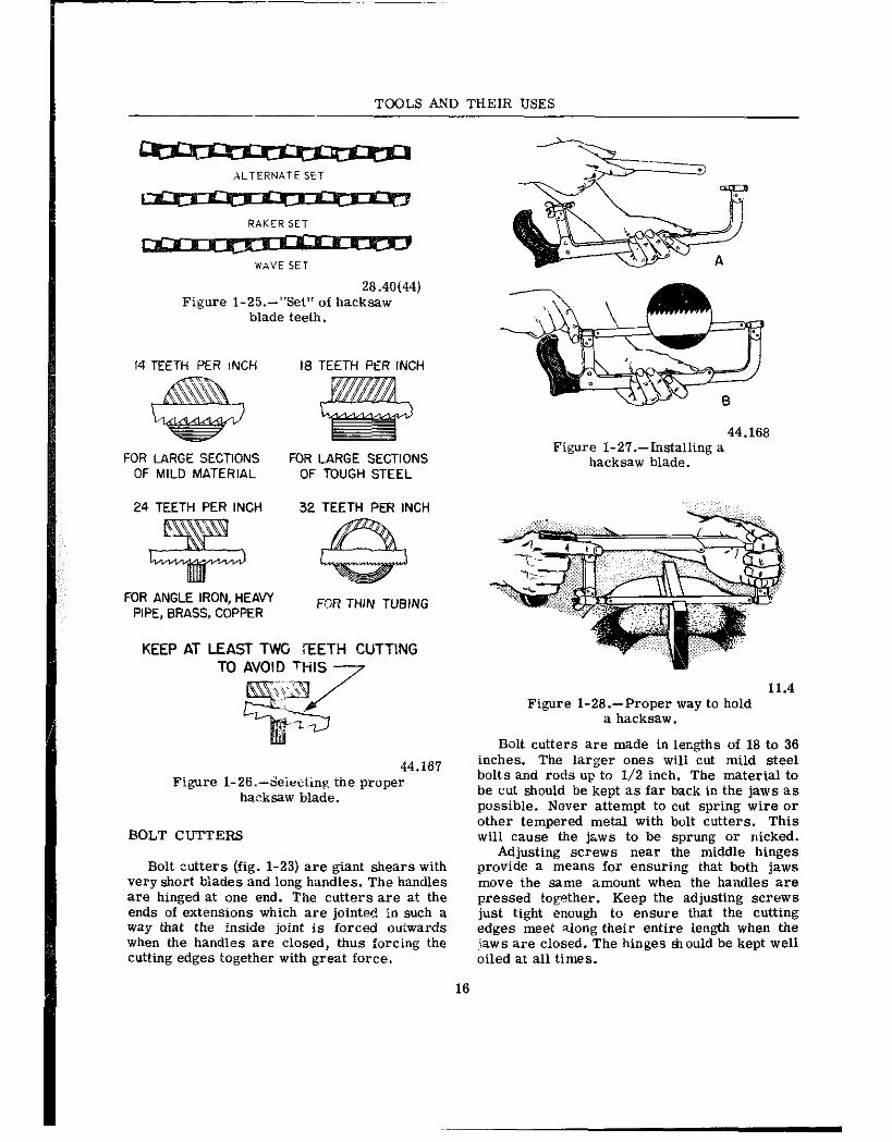
28.40(44) Figure l-25.-“Set” of hacksaw
blade teeth.
14 TEETH PER INCH
FOR LARGE SECTIONS FOR LARGE SECTIONS OF MILD MATERIAL OF TOUGH STEEL
24 TEETH PER INCH 32 TEETH PER INCH
FOR ANGLE IRON, HEAVY PIPE, BRASS, COPPER
F,ZR THIN TUBING
KEEP AT LEAST TW I-EETH CUTTING TO AVOID WIS 7
44.167 Figure 1-26.~Selecting the proper
hxksaw blade.
BOLT CUTTERS
Bolt cutters (fig. l-23) are giant shears with very short biades and long handles. The handles are hinged at one end. The cutters are at the ends of extensions which are jointed in such a way that the inside joint is forced outwards when the handles are closed, thus forcing the cutting edges together with great force.
44.168 Figure I-2?.-Installing a
hacksaw blade.
11.4 Figure l-28.-Proper way to hold
a hacksaw.
Bolt cutters are made in lengths of 18 to 36 inches. The larger ones will cut mild steel bolts and rods up to l/2 inch. The material to be cut should be kept as far back in the jaws as possible. Never attempt to cut spring wire or other tempered metal with bolt cutters. This will cause the jws to be sprung or nicked.
Adjusting screws near the middle hinges provide a means for ensuring that both jaws move the same amount when the haildles are pressed together. Keep the adjusting screws just tight enough to ensure that the cutting edges meet along their entire length when the jaws are closed. The hinges should be kept well oiled at all times.
16

Chapter I-COMMON HANDTOOLS
When using bolt cutters make sure your fingers are clear of the jaws and hinges. Take care that the bolt head or piece of rod cut off does not fly and injure you or someone else. If the cutters are brought together rapidly, some- times a bolt-head or piece of rod being cut off will fly some distance.
Bolt cutters are fairly heavy, so make sure that they are stored in a safe place where they will not fall and injure someone.
HACKSAWS
Hacksaws are used to cut metal that is too heavy for snips or boltcutters. Thus, metal bar stock can be cut readily with hacksaws.
There are two parts to a hacksaw; the frame and the blade. Common hacksaws have either an adjustable or solid frame (fig. I-24). Most hacksaws found in the Navy are of the adjust- able frame type. Adjustable frames can be made to hold blades from 6 to 16 inches long, while those with solid frames take only the length blade for which they are made. This length is the distance between the two pins that hoid the blade in place.
Hacksaw blades are made of high-grade tool steel, hardened and tempered. There are two types, the all-hard and the flexible. All hard blades are hardened throughout, whereas only the teeth of the flexible blades are hardened. Hacksaw blades are about one-half inch wide, have from 14 to 32 teeth per inch, and are from 8 to 16 inches long. The blades have a hole at each end which hooks to a pin in the frame. All hacksaw frames which hold the blades either parallel or at right angles to the frame are provided with a wingnut ox- screw to permit tightening or removing the blade.
The SET in a saw refers to how much the teeth are pushedout in opposite directions from the sides of the blade. The four different kinds of set are ALTERNATE set, DOUBLE ALTER- NATE set, RAKER set, and WAVE set. Three of these are shown in figure l-25.
The teeth in the alternate set are staggered, one to the left and one to the right throughout the length of the blade. On the double alternate set blade, hvo adjoining teeth are staggered to the right, two to the left, and so on. On the raker set blade, every third tooth remains straight and the other two are set alternately. On the wave (undulated) set bladt, short sec- tions of teeth are bent in opposite directions.
Using Hacksaws
The hacksaw is often used improperly. Al- though it can be used with limited success by an inexperienced man, a little thought and study given to its proper use will result in faster and better work a.nd less dulling and breaking of blades.
Good work with a hacksaw depends not only upon the proper use of the saw, but also upon the proper selection of the blades for the work to be done. Figure 1-26 will help you select the proper blade to use when sawing metal with a hacksaw. Coarse blades with fewer teeth per inch cut faster and are less liable to choke up with chips. However, finer blades with more teeth per inch are necessary when thin sections are being cut. The selection should t?? made so that,as each tooth starts its cut, the tooth ahead of it will still be cutting.
To make the cut, first install the blade in the hacksaw frame (fig. l-27) so that the teeth point away from the handle of the hacksaw. (Hand hacksaws cut on the push stroke.) Tighten the wingnut so that the blade is definitely under tension. This helps make straight cuts.
Place the material to be cut in a vise. A minimum of overhang will reduce vibration, give a better cut, and lengthen the life of the blade. Have the layout line outside of the vise jaw so that the line is visible while you work.
The proper method of holding the hacksaw is depicted in figure l-28. See how the index finger of the right hand, pointed forward, aids in guiding the frame.
When cutting, let your body sway ahead and back with each stroke. Apply pressure on the forward stroke, which ins the cutting stroke, hut not on the return Stroke. From 40 to 50 strokes per minute is the usual speed. Long, slow, steady strokes are preferred.
For long cuts (fig. l-29) rotate the blade in the frame so that the length of the cut is not limited by the depth of the frame. Hold ~the work with the layout line close to the vise jaws, raising the work in the vise as the sawing proceeds.
Saw thin metal as shown in figure l-30. Notice the long angle at which the blade enters the saw groove (kerf). This permits several teeth to be cutting at the same time.
Metal which is too thin to be held, as shown in figure l-30, can be placed between blocks of wood, as shown in figure l-31. The wood pro- vides support for several teeth as they are
17

TOOLS AND THEIR USES
44.169 Figure 1-29.-Making 2 long Cut
near the edge of stock.
44.170 Figure 1-30.-Cutting thin metal
with a hacksaw.
cutting. Without the wood, as shown at B in fig- ure 1-31, teeth will be broken due to excessire vibration of the stock and because individual teeth have to absorb the full power of the stroke.
Cut thin metal with layout lines on the face by using a piece of wood behind it (fig. l-32). Hold the wood and the metal in the jaws of the vise, using a C-clamp when necessary. The wood block helps support the blade and pro- duces a smoother cut. Using the wood only in back of the metal permits the layout lines to be seen.
To remove a frozen nut with a hacksaw, saw ima the nut as shown in figure l-33, starting the blade close to the threads on the bolt or stud and parallel to one face of the nut as shown in figure l-33A. Saw parallel to the bolt until the teeth of the blade almost reach the lo&washer. Lockwashers are hard and will ruin hacksaw blades, so do not try to saw them. Figure l-33B shows when to stop sawing. Then, with a cold chisel and hammer, remove this one side of the nut completely by opening the saw kerf. Put an adjustable wrench across this new flat and the p’le opposite,and again try to remove thefrozen nut. Since very little original metal remains
A s
44.171 Figure 1-31.-Cutting thin metal
between two wooden blocks.
44.172 Figure l-32.-Cutting thin metal using
wood block with layout lioes.
on this one side of the nut, the nut will either give or break away entirely and permit its removal.
To saw a wide kerf in the head of a cap screw 01‘ machine bolt, fit the hand hacksaw frame with two blades. side by side, and with teeth lined up in the same direction. With slow, steady strokes, saw the slot approximately one- third the thickness of the head of the cap screw as shown in figure l-34. Such a slot will per- mit subsequent holdingor turning with a screw- driver when it is impossible, due to close quarters, to use a. wrench.
Hacksaw Safety
The main danger in using hacksaws i.s injury to your hand if the blade breaks. The blade will break if too much pressure is applied, when the saw is twisted, when the cutting speed is too fast, or when the blade becomes loose in the frame. Additionally, if the work is not tight in the vise, it will sometimes slip, twisting the blade enough to break it.
18

Chapter I-COMMON BANDTOOLS
44.174 Figure 1-33.-Removing a frozen
nut with a hacksaw.
44.173 Figure 1-34.-Cutting a wide kerf in
the head of a capscrew or bolt.
29.15(44B)X Figure I-35.-Rod Saw and operations.
ROD SAWS
An improvement in industrial technology provides us with a tool that can cut material an ordinary hacksaw can’t even scratch. The rod saw (fig. l-35) acts like a diamond in its capa- bility of cutting hard metals and materials such as stainless steel,Inconel, titanium, and carbon phenolics.
The rod saw cG,ts through material by means of hundreds of tungsten-carbide particles per- manently bonded to the rod (see magnified por- tion of fig. l-35). The rod saw cuts through stainless steel and files with ease.
A unique feature 3f this saw is its capability of cutting on the forward and reverse strokes.
CHISELS
Chisels are tools that can be used for chip- ping or cutting metal. They will cut any metal that is softer than the materials of which they
are made. Chisels are made from a good grade tooi steel and have a hardened cutting edge and beveled head. Cold chisels are classified ac- cording to the shape of their points, and the width of the cutting edgedenotes their size. The most common shapes of chisels are flat (cold chisel), cape, round nose, and diamond point (fig. l-36).
The type chisel most commos!y used is the flat cold chisel, which serves to cut rivets, split nuts, chip castings, and cut thin metal sheets. The cape chisel is used for special jobs like cutting keyways, narrow grooves and square corners. Round-nose chisels make cir- cular grooves and chip iaside corners with a fillet. Finally, the diamond-point is used for cutting V-grooves and sharp corners.
As with other tools there is a correct tech- nique for using a ehise!. Select a chisel that is large enough for the job. Be sure to use a ham- mer that matches the chisel; that is, the larger the chisel, the heavier the hammer. A heavy
19

-63 CAPE CHISEL
cl i
HALF ROUND CHISEL vf3
Qm
DIAMOND POINT CHISEL
a 1
RCdND NOSE CHISEL
29.9M Figure l-36.-Types of points on
metal cutting chisel.
chisel will absorb the blows of a light hammer and will do virtually no cutting.
As a general rule, hold the chisel in the left hand with the thumb and first finger about 1 inch from the top. It should be held steadily but not tightly. The finger muscles should be relaxed, so if ‘he hammer strikes theband it will permit the hand to slide down the too! and lessen the effect of the blow. Keep the eyes on the cutting edge of the chisel, not on the head, and swing the hammer in the sameplane as the bodyof the chisel. If P-J have a lot of chiseling to do, slide a piece of rubber hose over the chisel. This will lessen the shock to your hand.
When using a chisel for chipping, always wear goggles to protect your eyes. If other men are working close by, see that they are protected fromflying chips byerecting a screen or shield to contain the chips. Remember that the time to take these precautions is before you start the jab.
FILES
A toolkit for nearly every raiing in tine Navy is not complete .unless it con’biins an assort- ment of files. There are a number of different types of files in common use, and each type may range in length from 3 to 18 inches.
TOOLS AND ‘THEIR USES
A. SINGLE L.ND DOUBLE-CUT FILES
DOUBLE CUT
BASTARD CUT SECOND CUT SMOOTH
6. DESlGN AND SPACING
OF FILE TEETH
C. FlLE NOMENCLATURE.
a ‘A @ SQUARE TR,ANG"LAR ROUND
aa-
HALF ROVND MILL FLAT
0. CROSS-SECTIONAL SHAPES OF FILES
1.20(44B)A Figure l-37.-File infOrmZktiO*.
20

Chaoter l-COMMON HANDTOOLS A~~
Grades
Files are graded according to the degree of fineness, and according to whether they have single- or double-cut teeth. The difference is ;“gent when you compare the iiles in figure
Single-cut files have rows of teeth cut par- allel to each other. These teeth are set at an angle of about 65 degrees with the centerline. You will use single-cut files for sharpening tools, finish filing, and drawfiling. They are also the best tools for smoothing the edges of sheet metal.
Files with crisscrossed rows of teeth are double-cut files. The double cut forms teeth that are diamond-shaped and fast cutting. You will use double-cut files for quick removal of metal, and for rough work.
Files are also graded according to the spac- ing and size of their teeth, or their coxseness
and fineness. Some of these grades are pic- tures in fig. l-37B. In addition to the three grades shown, you may use some DEAD SMOOTH files, which have very fine teeth, and some ROUGH files with very coarse tee%. The fine- ness or coarseness of file teeth is also influ- enced by the length of the file, (The length of a file is the distance from the tip to the heel, and does not include the tang (fig. l-37C).) When you have a chance, compare the actual size of the teeth of a B-inch, single-cut smooth file and a 12-inch, single-cut smooth file; you will no- tice the6-inch file has more teeth per inch than the l&inch file.
Shapes
Files come in different shapes. Therefore, in selecting a file for a job, the Ghape of the finished work must be considered. Some of the cross sectional shapes are shown in figure I-37D.
D. FlLlNG ROUND METAL STOCK
120(44B)B Figure l-38.-Filing operations.
21

TOOLS AND THEIR USES -
TRIANGULAR files are tapered (longitudi- nally) on all three sides. They are used to fiie acute internal angles, and to clear out square corners. Special triangular files are used to file saw teeth.
MILL files are tauered in both width and thickness. One edge ias no teeth and is knswn as a SAFE EDGE. Mill files are used for smoothing lathe work, drawfiling, and other fine, precision work. Mill files are always single-cut.
FLAT files are general-purpose files and may be either single- or double-cut. They are tapered in width and thickness. HARD files, not shown, are somewhat thicker than flat files. They taper slightly in thickness, but their edges are parallel.
The flat or hard files most often used are the double-cut for rough work and the single-cut, smooth file for finish work.
SQUARE files are tapered on all four sides and are used to enlarge rectangular-shaped holes and slots. ROUND files serve the same purpose for round openings. Small round files are often called “rattail” files.
The HALF ROUND file is a general-purpose tool. The rounded side is used for curved sur- faces and the flat face on flat surfaces. When you file an inside curve, use a round of half- mund file whose curve most nearly matches the curve of the work.
Kits of small files, often called “Swiss Pat- tern” or “Jewelers” files, are used to fit parts of delicate mechanisms, and for filing work on instruments. Handle these small files care- fully because they break easily.
FILING OPERATIONS
Using a file is an operation that is nearly in- dispensable when working with metal. You may be crossfiling, drawfiling, using a file card, or even polishing metal. Let’s examine these operations.
When you have finished using afile it may be necessary to use an abrasive cloth ox- paper to finish the product. Whether this is necessary depends en how fine a finish you want on the work.
CROSSFILlXG.-Figure l-38A shows a piece of mi1.d steel being crossfiled. This means that the file is being moved across the surface of the work in approximately a crosswise direction.
A. FOLlSHlNG METAL WITH ABRASIVE CLOT” WRAPPED AROUND A FILE
B. ALTERNATE METHODS FOR POLISHING METAL SURFACE
C. POLISHING ROUND METAL STOCK
44.135:.136
Figure l-39.-Polishing operations.
22

Chapter l-COMMON HANDTOOLS
For best results, keep your feet spread apart to steady yourself as you file with slow, full- length, steady strokes. The file cuts as you push it-ease up on the return stroke to keep from dulling the teeth. Keep your file clean.
Figure l-38B shows the alternate positions of the file when an exceptioilaliy flat surface is required. Using either position first, file across the entire length of the stock. Then, using the other position, file across the entire length of the stock again. Because the teeth of the file pass over the surface of the stock from two directions,the higb spots and low spots will readily be visible after filing in both positions. Continue filing first in one position or direc- tion and then the other until the surface has been filed flat. Test the flatness with a straight edge or with prussian blue and a surface plate.
DRAW FILING.-Draw filing produces afiner surface finish and usually a flatter surface than crossfiling. Small parts, as shown in figure l-38C, are best held in a vise. Hold the file as shown in the figure; notise that the arrow indi- cates that the cutting stroke is away from you when the handle of the file is held in the right hand. If the handle is held in the l&t hand, the cutting stroke will be toward you. Lift the file away from the surface of the work on the re- turn stroke. When draw filing will no longer improve the surface textwe, wrap a piece of abrasive cltoh around the file and polish the surface as shown in figure 1-39.4.
USE OF FILE CARD.-As you file, the teeth of the file may “clog up” with some of the metal filings and scratch your work. This condition is known as PINNING. You can prevent pinning by keeping the file teeth clean. Rubbing chalk be- tween the teeth will help prevent pinning, too, but the best method is to clean the file fre- quently with a FILE CARD or brush. A file card (fig. l-40) has fine wire bristles. Brush with a F’llling motion, holding the card parallel to the POWS of teeth.
Always keep the file clean, whether you’re filing mild steel or other metals. Use chalk liberally when filing nonferrous metals.
FILING ROUND METAL STOCK.-Figure l-38D shows that;as a file is passed over the surface of round work, its angle with the work is changed. This results in a rocking motion of the file as it passes over the work. This rock- ing motion permits all the teeth on the file to
44.11 Figure 1-40.-File cleaner.
make contact and cut as they pass over the work’s surface, thus tending to keep the file much cleaner and thereby doing better work.
POLISHING A FLAT METAL SURFACE.- When polishing a flat metal surface, first draw file the surface as shown in fig. l-38C. Then, when the best possible draw filed surface has been obtained, proceed with abrasive cloth, often called emery cloth. Select a grade of cloth suited to the draw filing. If the draw fil- ing was well done only a fine cloth will be needed to do the polishing.
If your cloth is in a roll, and the job you are polishing is the size that would be held in a vise, tear off a 6” or 8” length of the 1” or 2” width. If you are using sheets of abrasive cloth, tear off a strip from the long edge of the 8” by 11” sheet.
Wrap the cloth around the file (fig. l-39A) and hold the file as you would for draw filing. Hold the end of the cloth in place with your thumb. In polishing, apply a thin iilm of lubri- cating oil on the surface being polished and use a double stroke with pressure on both the for- ward and the backward strokes. Note that this is different from the drawfiling stroke in which you cut with the file in only one direction.
When further polishing does not appear to improve the surface, you are ready to use the next finer grade of cloth. Before changing to the finer grade, however, reverse the cloth so that its back is toward the surface being polished.
Workthe reversed cloth back and forth in the abrasive-laden oil as an intermediate step be- tween grades of abrasive cltoh. Then, with the
23

TOOLS AND THEIR USES
solvent available in your shop, clean the job thoroughly before proceeding with the next finer grade of cloth. Careful cleaning ketween grades helps to ensure freedom fro.* scratches.
For the final polish, use a strip of wocus cloth-first the face and then the back-with plenty of oil. When polishing is complete, again carefully clean the job with a solvent and pro- tect it, with oil or other means, from rusting.
Figure l-39B(A) shows another way to polish in which the abrasive cloth is wrapped around a block of wood. In firrure l-39B(B), the cloth has simply been folded& form a sd’from which a worn, dull surface can be removed by simply tearing it off to expose a new surface.
THE POlNT
LIP OR DEAD MARGlN
POLISHING ROUND METAL STOCK.-lnfig- ure l-39C, a piece of round stock is being polished with a strip of abrasive cloth which is “seesawed” back and forth as it is guided over the surface being polished.
BODY
Remember that the selection of grades of abrasive cloth, the application of oil, and the cleaning between grades, applies to polishing regardless of how the cloth is held or used.
Care of Files
A new file should be broken in carefully by using it first on brass, bronze, or smooth cast iron. Just a few of the teeth will cut at first, so use a light pressure to prevent tooth breakage. Do not break in a new file by using it first on a narrow surface.
Protect the file teeth by hanging your files in a rack when they are not in use, or by placing them in drawers with wooden partitions. Your files should not be allowed to rust-keep them away from water and moisture. Avoid getting the files oily. Oil causes a file to slide acros8 the work and prevents fast, clean cutting. Files that you keep in your toolbox should be wrapped in paper or cloth to protect their teeth and pre- vent damage to other tools.
Never use a file for prying or pounding. The tang is soft and bends easily. The body is hard and extremely brittle. Even a slight bend or a fall to the deck may cause a file to snap in two. Do not strike a file against the bench or vise to
Figure 1-41.-Twist drill nomenclature.
TANG
clean it-use a file card. handle and it bumps something or jams to a
Safety sudden stop, the tang may be driven into your hand. To put a handle on a file tang, drill a
Never use a file unless it is equipped with a hole in the handle, slightly smaller than the tight-fitting handle. If you use a file without the tang. Insert the tang end, and then tap the end
24

Chapter l-COMMON RANDTOOLS
of the handle to seat it firmly. Make sure you get the handle on straight.
TWIST DRILLS
Makin: a hole in a piece of m@tal is gener- ally a simple operation, but in most cases is an important and a precise job. A large number of different tools and machineshave been designed so that holes may be made speedily, economi- cally, and accurately in all kinds of material.
In order to be abie to use these tools effi- ciently, it is well to become acquainted with them. The most common tool for making holes in metal is the twist drill. It consists of a cylindrical piece of steel with spiral grooves. One end of the cylinder is pointed while the other end is shaped so that it may be attached to a drilling machine. The grooves, usually called FLUTES, may be cut into the steel cyl- inder, or the flutes may be formed by twisting a flat piece of steel into a cylindrical shape.
The principal parts of a twist drill are the body, the shank, and the point (fig. l-41). The dead center of a drill is the sharp edge at the extreme tip end of the drill. It is formed by the intersection of the cone-shaped surfaces of the point and should always be in the exact center of the axis of the drill. The point of the drill should not be confused with the dead cen- ter. The point is the entire cone-shaped sur- face at the end of the drill.
The lip or cutting edge of a drill is that part of the point that actually cuts away the metal when drilling a hole. It is ordinarily as sharp as the edge of a knife. There is a cutting edge for each flute of the drill.
The lip clearance of a drill is the surface of the point that is ground away or relieved just back of the cutting edge of the drill. The strip along the inner edge of the body is called the margin. It is the greatest diameter of the drill and extends the entire length of the flute. The diameter of the margin at the shank end of the drill is smaller than the diameter at the point. This allows the drill to revolve withoui binding when drilling deep holes.
The shank is the part of the drill which fits into the socket, spindle, or chuck of the drill press. Several types exist (fig. l-42).
A tang is found only on tapered-shank drills. It is designed to fit into a slot in the eo:ket or spindle of a machine. It may bear a portion of the driving torque, but its principal us~z is to
TAPERED STRAIGHT SQUARE
44.20(44B) Figure l-42.-Representative shanks.
make it easy to remove the drill from the socket of the driving machine.
Twist drills are provided in various sizes. They are sized by letters, numerals, and fractions.
Table l-l illustrates the relationship, by decimal equivalents, of all drill sizes (letter, number, and fractional) from number 80 to l/2 inch. Note how the decimal sizes increase as the number of the drill decreases.
Sets of drills are usually made available ac- cording to the way the sizes are stated; that is “sets of letter drills” or “sets of number drills.” However, twist drills of any size (let- ter, number, or fraction) are available indi- vidually if desired.
The maintenance of twist drills and more about how to use them on specific jobs are dis- cussed later.
COUNTERSINKS
Countersinking is the operation of beveling the mouth of a hole with a rotary tool called a countersink (fig. l-43). The construction of the countersink is similar to the twist drill. There are four cutting edges, which are taper ground, to the angle marked on the body.
A countersink is used primarily to set the head of a screw or rivet flush with the material in which it is being placed. Countersinks are made in a number of sizes. One size usually takes care of holes of several different sizes. That is, the same countersink can be used for holes from l/4 inch to l/2 inch in diameter. Remove only enough metal to set the screw or rivet head flush with the materiai. If you
25

TOOLS AND THEIR USES
Table 1-l.-Decimal Eqlliv;lents of Drill Sizes
Drill
80
;i l/64 71 76 75 74 13 72 71 70 69 68 l/32 67 66 65 64 63 62 61 60 59 58 57 56 3/64 55
ii l/16 52 51 50
Decimal
0.0135 0.0145 0.016 0.0156 0.018 0.02 0.021 0.0225 0.024 0.025 0.026 0.026 0.0292 0.031 0.03125 0.032 0.033 0.035 0.036 0.037 0.038 0.039 0.04 0.041 0.042 0.043 0.0465 0.046675 0.052 0.055 0.0595 0.0625 0.0635 0.061 0.07
Drill
49 46 5/64 47 46
::
4”; 3/32 41 40 39 38 31 36 7/64 35 34 33 32 31 l/8 30 29 28 9/64 27 26 25 24 23 5/32 22 21
Decimal hill Decimal Drill Decimal
0.073 0.076 0.076125 0.0765 0.061 0.082 0.086 O.OEQ 0.0935 0.09375 0.096 0.09a 0.0995 0.1015 0.104 0.1055 0.109375 0.11 0.111 0.113 0.116 0.12 0.125 0.1285 0.136 0.1405 0.140625 0.144 0.147 0.1495 0.152 0.154 0.15625 0.157 0.159
20 19 16 11/64
:i 15 14
$16 12 11 10 9 6 7 13/64 6
: 3 l/32 2 1 A 15,'64 B c D E l/4 F G 11/64
0.161 0.166 0.1695 0.171875 0.173 0.177 0.16 0.182 0.165 0.1875 0.189 0.191 0.1935 0.196 0.199 0.201 0.203125 0.204 0.2055 0.209 0.213 a.21875 0.221 0.226 0.234 0.234375 0.238 0.242 0.246 0.25 0.25 0.257 0.261 0.265625
H I J K Q/32 L M 19/64 N 5/16 0
$64 Q R 11/32 S
:3,64
$6 V W 25/64 X
$32
22,64 7/16
z;:
0.266 0.272 0.271 0.281 0.28125 0.29 0.295 0.296875 0.302 0.3125 0.316 0.323 0.328125 0.332 0,339 0.34375 0.346 0.358 0.359375 0.366 0.375 0.317 0.386 0.390625 0.397 0.404 0.40625 0.413 0.421875 0.4375 0.453125 0.46875 0.484375 0.5
44.209
remove too much material the hole will enlarge and weaken the work.
REAMERS
Select the countersink with the correct lip Reamers are used to enlarge and true a angle to correspond with the screw oi” rivet hole. The reamer consists of three parts-the head being used. These countersinks can be body, the shank, and the blades. The shank has turned by any machine that will turn a twist drill. a square tang to allow the reamer to be held
26

28.59(44) Figure 1-43.-Countersink.
5.10.1 Fibvre 1-44.-Above-solid spiral flute
reamer. Below-solid straight flute reamer.
5.10.2 Figure 1-45.-Expansion reamer.
with a wrench for turning. The main purpose of the body is to support the blades.
The blades on a reamer are made of steel and hardened to such an extent that they are brittle. For this reason you must be careful when usi,ng and storing the reamer to protect the blades from chipping. When you are ream- ing a hole, turn the reamer inthe CUTTING DI- RECTION ONLY. This will prevent chipping or dulling of the blades. Great care should be used to assure even, steady turning. Other- wise, the reamer will “chatter,” causing 9 hole to become marked or scored. To prel znt damage to the reamer while not in use, wrap it in an oily cloth and keep it in a box.
Reamers of the types shown in figure l-44 are available in any standard size. They are also availabie in size variations of .OOl” for special work. A solid straight flute reamer lasts longer and is less expensive than the ex- pansion reamer. However, the solid spiral ilute reamer is preferred by craftsmen because it is less likely to chatter.
For general purposes, an expansion reamer (fig. l-45) is the most practical. Tbis reamer can usually be obtained in standard sizes from
CENTER PUNCH
PRICK PUNCH
DRIFT OR STARTING PUNCH
Chapter I-COMMON HANDTOOLS
PIN PUNCH
ALINING PUNCH
HOLLOW SHANK GASKET PUNCH
1.18(448) Figure 1-46.-Punches.
l/4 of an inch to 1 inch, by 32nds. It is designed to allow the blades to expand l/32 of an inch. For example, the l/4-inch expansion reamer will ream a l/4-inch to a Q/32-inch hole. A 9/32-inch reamer will enlarge the hole from 9/32 of an inch to 5/16 of an inch. This range of adjustment allows a few reamers to cover sizes up to 1 inch.
Reamers are made of carbon steel and high- speed steel. In general, the cutting blades of a high-speed reamer lose their keenness more quickly than a carbon steel reamer. However, after that keenness is gone, it will last longer than the carbon reamer.
PUNCHES
A hand punch is a tool that is held inthe harid and struck on one end with a hammer. There are many kinds of punches designed to do a variety of jobs. Figure 1-46 shows several types of punches. Most punches are made of tool steel. The part held in the hand is usually octagoaai shaped, or it may be knurled. This
27

TOOLS AND THEIR USES
PUNCH Jo’NTS
28.32 Figure I-47.-Punchmg
mating parts of a mechanism.
prevents the tool from slipping around in the hand. The other end is shaped to do a particu- lar job.
When you use a punch, there are two things to remember:
1. When you hit the punch fl~u do not want it to slip sideways over your work.
2. You do not want the hammer to slip off the punch and strike your fingers. You can eliminate both these t:coubles by holding the punch at right angles to the work, and striking the punch squarely with your hammer.
The ceater punch, as the name implies, is used for marking the center of a hole to be driiied. U you try to driii a hole without first punching the center, the drill will %ander” or “walk away” from the desired center.
Another use of the center punch is to make corresponding marks on two pieces of an as- sembly to permit reassembling in the original positions. Before taking a mechanism apart, make a pair of center punchmarks in one or more places to help in reassembly. To do this, select places, staggered as shown in figure l-47, where matching pieces are joined. First clean the places selected. Then scribe a line across the joint and center punch the line on both sides of the joint, with single and double marks as shown to eliminate possible errors. In reassembly, refer first to the sets of punch- marks to determine the approximate position of the parts. Then line up the scribed lines to de&-mine the exact position.
Automatic center punches are useful for lay- out work. They are operated by pressing down
A B c
44.83 Figure l-48 .-Marking the inter-
section of lines with a prick punch.
on the shank by hand. Au inside spring is com- pressed and released automatically, striking a blow on the end of the punch. Tbe impression is light, but adequate for marking, and serves to locate the point of a regular punch when a deeper impression is required.
The point of a center punch is accurately ground central with the shank, usually at a 60-90 degree angle, and is difficult to regrind by hand with any degree of accuracy. It is, therefore, advisable to take care of a center punch and not to use it on extremely hard materials. When extreme accuracy is required a prick punch is used. Compare the point angle of the center and prick punches.
To make the intersection of two layout lines, bring the point of the prick punch to the exact point of intersection and tap the punch lightly with a hammer. If inspection shows that -the exact intersection and the punchmarkdo not co- incide, as at A in figure l-48, slant the punch as shown at B and again strike with the ham- mer, thus enlarging the punchmark and cen- tering it exactly. When the intersection has been correctly punched, finish off with a light blow on the punch held in au upright position. C shows the corrected punchmark.
DRIFT punches, sometimes called “starting punches,” have a long taper from the tip to the body. They are made that way to withstand t& shock of heavy b!ows. They may be used for knocking out rivets after the heads have been
28

Chapter l-COMMON HANDTOOLS
TAPER PIPE
TAPER “AND
CHAMFER LENGTH
PLUG “A,$N~TIDNAL
chiseled off, or for freeing pins which are “frozen” in their holes.
After a pin has been loosened or partially driven out, the drift punch may be too large to finish the job. The followup tool to use is the PIN PUNCH. It is designed to follow through the hole without jamming. Always use the largest drift or pin punch that will fit the hole. These punches usually come in sets of three to five assorted sizes. Both oi these punches will have flat points, never edged or rounded.
To remove a bolt or pin that is extremely tight, start with a drift punch that has a point diameter that is slightly smaller than the diam- eter of the object you are removing. As soon as it loosens, finish driving it out with a pin punch. Never use a pin punch for starting a pin because it has a slim shank and a hard blow may cause it to bend or break.
For assembling units of a machine an ALINEMENT (alining) punch is invaluable. It is usually about 1 foot long and has a long gradual taper. Iis purpose is to line up holes in mating parts.
Hollow metal cutting punches are made from hardened tool steel. They are made in various sizes and are used to cut holes in light gage sheet metal.
Other punches have beendesigned for special uses. One of these is the soft-faced drift. It is made of brass or fiber and is used for such jobs as removiag shafts, bearings, and wrist pins from engines. It is generally heavy enough to resist damage to itself, bui soft enough not to injure the finished surface on the part that is being driven.
You may have to make gaskets of rubber, cork, leather, or composition materials. For cutting holes in gasker materials a hollow shank GASKET PUNCH may be used (fig. l-46). Gasket punches come in sets of various sizes to accommo&& standard bolts and studs. The cutting end is tapered to a sharp edge to pro- duce a clean uniform hole. To use the gasket punch, place the gasket material to be cuf on a piece of hard wood or lead so that the cutting edge of the punch will not be damaged. Then strike the punch with a hammer, driving it through the gasket where holes are required.
TAPS AND DIES
Taps and dies are used to cut threads in metal, plastics, or hard rubber. The taps are used for cutting internal threads, and the dies
29
BOTTOMING HAND
115.1 Figure l-49.-Types of common taps.
are used to cut external threads. There are many different types of taps. However, the most common are the taper, plug, bottoming, and pipe taps (fig. 1-49).
The taper (starting) hand tap has a chamfer length of 8 to 10 threads. These taps are used when starting a tapping operation and when tap- ping through holes.

TOOLS AND THEIR USES
short chamfer length of only 1 to 1 l/2 threads SQLIARE PIPE _,,.,
‘.~~ for this purpose. This tap is always used after the plug tap has already been used. Both the taper and plug taps should precede the use of the bottoming hand tap.
Pipe taps are used for pipe fittings and other placeswhere extremelytight fitsare necessary. The tap diameter, from end to end of threaded portion, increases at the rate of 3/4 inch per
RElHREAD!NG foot. All the threads on this tap do the cutting, as compared to the straight taps where only
11.5.4 the nonchamfered portion does the cutting. Figure l-50.-Types of solid dies. Dies are made in several different shapes
Plug hand taps have a chamfer ien$l~ of 3 to and are of the solid or adjustable type. The 5 threads and are designed for use after the square pipe die (fig. l-50) will cut American taper tap. Standard Pipe Thread only. It comes m a va-
Bottoming hand taps are used for threading riety of sizes for cutting threads on pip’ with the bottom of a blind hole. They have a very diameters of l/8 inch to 2 inches.
TWO-PIECE RECTANGULAR PIPE DIE
--...~~---~, TWO-PIECE COLLET DIE
SCREW ADJUSTING TYPE OPEN ADJUSTING TYPE
Figure 1-51.-Types of adjustable
30
dies.
11.5.2

Chapter l-COMMON HANDTOOLS --
SINGLE SCREW 0,~5TcJCI iHPEE SCREW DIESTOCI(
11.5.6 Figure 1-52.-Diestocks, diecollet, and tap wrenches.
44.31 Figure 1-53.-Adjustable die guide and ratchet diestocks.
A rethreading die (fig. I-50) is used prin- cipally for dressing over bruised or rusty threads ax screws or bolts. It is available in a variety of sizes for rethreading American Standard Coarse and Fine threads. These dies are usually hexagon in shape and can be turned with a socket,box, open-end,or any wrench that will fit. Rethreading dies are available in sets of 6, 10, 14, and 28 assorted sizes in a case.
31
Round split adjustable dies (fig. l-51) are called “Button” dies and can be used in either hand diestocks 01‘ machine holders. The ad- justment in the screw adjusting type is made by a fine-pitch screw which forces the sides of the die apart or aiiows them to spring together. The adjustment in the open adjusting types is made by means of three screws in the holder, one for expanding and two for compressing the

TOOLS AND THEIR USES
BOLT AN0 SCREW THREADlNG SET W,TH ROW40 AoNST*sLE SPLIT DIES,
DIESTOCKS. TAPS, TAP WRENCHES, AN0 SCREwORI”ERS
44.32 Figure l-54.-Threading sets.
dies. Round split adjustable dies are available in a variety of sizes to cut American Standard Coarse and Fine threads, special form threads, and the standard sizes of threads that are used in Britain and other European countries. For hand threading, these dies are held in diestocks (fig. l-52). One type die stock has three pointed screws that will hold round dies of any construction, although it is made specifically for open adjusting-type dies.
Two piece coil& dies (fig. 1-51) are used with a collet cap (fig. l-52) and collet guide. The die halves are placed in the cap slot and are held in place by the guide which screws into the underside of the cap. The die is adjusted by means of setscrews at both ends of the in- ternal slot. This type of adjustable die is issued in various sizes to cover the cutting range of AmericanStandard Coarse and Fine and special form threads. Diestocks to hold the dies come in three different sizes.
e4IERNAL 32 TP,
44.33 Figure i-55.-Thread chasers.
Two-piece rectangular pipe dies (fig. 1-51) are available to cut Amtrican Standard Pipe threads. They are held in ordinary or ratchet- type diestocks (fig. l-53). The jaws of the dies are adjusted by means of setscrews. An adjust- able guide serves to keep the pipe in alinement with respect to the dies. The smooth jaws of the guide are adjusted by means of a cam plate; a thumbscrew locks the jaws firmly in the de- sired position.
Threading sets are available in many dif- ferent combinations of taps and dies, together with diestocks,tap wrenches, guides and neces- sary screwdrivers and wrenches to loosen and tighten adjusting screws and bolts. Figure l-54 i!l,ustra?es typical threading set for pipe, bolts, and screws.
Never attempt to sharpen taps or dies. Sharpening of taps and dies involves several highly precise cutting processes which inv&v~e the thread characteristics and chamfer. These sharpening procedures must be done by experi- enced personnel in order to maintain the ac- curacy and the cutting effectiveness of taps and dies.
Keep taps and dies clean and well oiled when not in use. Store them so that they do not con- tact each other or other tools. For !ong periods of storage, coat taps and dies with a rust- preventive compound, place in individual or standard threading set boxes,and store in a dry place.
THREAD CHASERS
Thread chasers are threading tools that have several teeth and are used to rethread
32

Chapter l-COMMON HANDTOOLS
(chase) damaged external or internal threads (fig. l-55). These tools are available to chase standard threads. The internal thread chaser has its cutting teeth located on a side face. The external thread chaser has its cutting teeth on the end of the shaft. The handle end of the tool shaft tapers to a point.
SCREW AND TAP EXTRACTORS
Screw extractors are used to remove broken screws without damagingthe surrounding mate- rial or the threaded hole. Tap extractors are used to remove broken taps.
Some screw extractors (fig. l-56A) are straight, having flutes from end to end. These extractors are available in sizes to remove broken screx:s having l/4 to l/2 inch outside diameters. Spiral tapered extractors are sized to remove screws and bolts from 3/16 inch to 2 !/6 inches outside diameter.
Mosi sets of extractors include twist drills and a drill guide. Tap extractors are similar to the screw extractors and are sized to re- move taps ranging from 3/16 to 2 l/8 inches outside dianeier L .
To remove a broken screw or tap with a spiral extractor, first drill a hole of proper size in the screw or tap. The size hole re- quired for each screw extractor is stamped on it. The extractor is then inserted in the ho!@, and turned counterclockwise to remove the de- fective component.
If the tap has broken off at the surface of the work, or slightly below the surface of the work, the straight tap extractor shown in figure 1-56 may remove it. Apply a liberal amount of pene- trating oil to the broken tap. Place the tap ex- tractor over the broken tap and lower the upper collar to insert the four sliding prongs down into the four flutes of the tap. Then slide the bottom collar down to the surfaxe of the work so that it will hold the prongs tightlyagainst the body of the extractor. Tighten the tap wrench on the square shank of the extractor and care- fully work the extractor back and forth to loosen the tap. It may be necessary to remove the extractor and strike a few sharp blows with a small hammer and pin punch to jar the tap loose. Then reinsert the tap remover and carefully try to back the tap out of the hole.
A. STRAIGHT TAP
A
8. SPIRAL SCREW
4.37:44.191 Figure l-56.-Screw and tap extractors.
PIPE AND TUBING CUTTERS AND FLARING TOOLS
Pipe cutters (fig. l-57) are used to cut pipe made of steel, brass, copper, wrought iron, and lead. Tube cutters (fig. l-57) are used to cut tubing made of iron, steel, brass, copper, and aluminum. The essential difference between pipe and tubing is that tubing has considerably thinner walls. Flaring tools (fig. l-56) are used to make sinale or double flares in the ends of tubing.
Two sizes of hand pipe cutters are generally used in the Navv. The No. 1 pipe cutter has a cutting capacity-of l/6 to 2 inches,and the No. 2 pipe cutter has a cutting capacity of 2 to 4
33

TOOLS AND THEIR USES
Figure l-57.-Pipe and tubing cutters. 44.36
inches. The pipe cutter (fig. l-57) has a spe- 7/16-,and l/a-inch outer diameter (o.d.) tubing, cial alloy-steel cutting wheel and two pressure a clamp to lock the tube in the die block, and a rollers which are adjusted and tightened by yoke that slips over the die block and has a turning the handle. compressor screw and a cone that forms a 45’
Most TUBE CUTTERS closely resemble pipe flare or a bell shape on the end of the tube. The cutters, except that they are of lighter con- screw has a T-handle. A double flaring tool struction. A hand screw feed tubing cutter of l/&inch to 1 l/4-inch capacity (fig. l-57) has
has the additional feature of adapters that turn in the edge of the tube before a regular 45”
two rollers with cutouts located off center so double flare is made. It consists of a die block that cracked fiares may be held in them and cut off without waste of tubing. It also h,as a re-
with holesfor 3/l&, l/4-, 5/16-, 3/E-, and l/2- inch tubing, a yoke xvith a screw and a flaring
tractable cutter blade that is adjusted by turn- cone, plus five adapters for different size tub- ing a knob. The other totbe cutter shown is de- ing, all carried in a metal case. signed to cut tubing up to and including 3/4 and 1 inch outside diameter. Rotation of the tri- WOGDCUTTING HANDTOOLS angular portion of the tube cutter within the tubing will eliminate any burrs. A man working with wood uses a large va-
FLARING TOOLS /fig. l-56) are used to flare soft copper, brass, or aluminum. The
riety of handtools. He should be familiar with
Single flaring tool consists of a split die block these tools,their proper rarnes,the purpose for
that has holes for 3/16-, l/4-, 5/16-, 3/S, which thev are used, and how to keep them in good condition.
34

Chaptev l-COMMON HANDTOOLS
DOUBLE FLARING TOO:
44.37 Figure 1-58.-Flaring tools.
29.15(44) Figure 1-59.-Nomenclature of a handsaw.
29.15A Figure 1-60.-“Set” of band saw teeth.
In this section of the text, only the basic woodcutting tools are covered. It includes tools that any man in the Navy may have the c :cac;ion to use during his career.
k~ .ND.%WS
‘_ most common carpenter’s handsaw con- sists of a steel blade with a handle at one end.
35
TEETH OF RIP SAW TEEW OF cRossc”~s*!#
29.15(44B) Figure I-61.-Comparing rip and
crosscut-saw teeth.
iIne i%ade is narrower at the end opposite the han:J!e. This end of the blade is called the .‘Iaoint” or “toe.” The rnd of the blade nearest thr handle is called the “heel” (fig. l-59). One edge of the blade has teeth, which act as two rows of cutters. When the saw is used, these teeth cut two parallel grooves close together. The chips (sawdust) are pushed out from be- tween the grooves (kerf) by the beveled part of the teeth. The teeth are bent alternately to one side or the other, to make the kerf wider than the thickness of the blade. This bending is called the “set” of the teeth (fig. l-60). The number of teeth per inch, the size and shape of the teeth, and the amount of set depend on the

TOOLS AI:D THEIR USES
COPlN‘ SAW
29.20-22 Figure 1-62.-Special saws.
use to be wade of the saw and the material to be cut. Carpenter’s handsaws are described by the number of points per inch. By custom, there ie always one more point than there are teeth per inch. A number stamped near the handle gives the number of points of the saw.
Cross-cut and Rip Saws
Woodworking handsags designed for general cctting consist of RIPSAWS and CROSSCUT saws. Ripsaws are used for cutting with the grain and crosscut saws are for cutting across the grain.
The major difference between a ripsaw and a crosscut saw is the shape of the teeth. A tooth with a square-faced chisel-type cutting edge,like the ripsaw tooth shown in figure 1-61, does a good job of cutting with the grain (called ripping), but a poor job of cutting across the grain (called crosscutting). A tooth with a beveled, knifetype cutting edge, like the cross- cut saw tooth shown in the same figure, does a good job of cutting across the grain, but a poor job of cutting with the grain.
Special Purpose Saws
The more common types of saws used for special purposes are shown in figure 1-62. The BACKSAW is I crosscut saw designed for saw- ing a perfectly straight line across the fax! of ir piece of stock. A heavy steel backing along the too of the blade keeps the blade perfectly straight-
The DOVETAIL saw is a special type oi backsaw with a thin, narrow blade and a chisel- type handle.
The COMPASS saw is a long, narrow, taper- ine riosaw desicned for cutting out circular or other ‘nonrect&gular sections from within the margins of. a board or panel. A hole is bored near the cutting line to start the saw. A KEY- HOLE saw is simply a finer,narrower compass saw.
The COPING saw is used to cut along curved lines as shown in figure l-62.
Saw Precautions
A saw that is not being used should be hung up or stowed in a toolbox. A toolbox designed for holding saws has notches that hold them on edge, teeth up. Stowing saws loose in a toolbox may allow the saw teeth to become dulled or bent by contacting other tools. Some right and wrong methods of using and caring for a saw are shown in figure l-63. Be sure to read the captions for each section of the illustration.
Before using a saw, be sure there are no nails or other edge-destroying objects in the line of the cut. When sawing out a strip of waste, do not break out the strip by twisting the saw blade. This dulls the saw and may spring or break the blade.
Be sure that the saw will go through the full stroke witbout striking the floor or some other object. If the work cannot 5i r-isod bigb enough
36

Chapter l--COMMON HANDTOOLS
WRONG RlGHl
Figure l-63.-Care of handsaws. 44.14
to obtzin full clearance for the saw, you must carefully !imit the length of each stroke.
Using A Hand Saw
Tv sa-w across the gain oi the stock, use the crosscut saw, and to saw with tie grain, use a ripsaw. Study the teeth in both kinds of saws so you can readily identify the saw that you need.
Place the board on a saw horse (fig. l-64), or some other suitable object. Hold the saw in the right hand and extend the first finger along the handle as shown in the figure. Grasp the board a6 shown and take a position so that an
imaginary line passing lengthwise of the right forearm will be at an angle of approximately 45 degrees with the face of the board. :Be sure the side of the saw is plumb or at right angles with the face of the board. Place the heel of the saw on the mark. Keep the saw inline with the fore- arm and pull it toward you to start the cdt.
To begin witch, take short, iight si?‘okes, gradually increasing the strokes to the full length of the sa,w. Do not force or jerk the saw. Such procedure will only make sawing more difficult. The arm that does the sawing should swing clear of your body so that the handle of
37

TCXX.3 AND THEIR USES
Figure l-F4.-Proper position for sawing a board to size.
44.102 Figure 1-65.-Using
a wedge in a saw kerf to prevent binding.
the saw operates at your side rather than in front of you.
Use one hand to operate the saw. You nXiy be tempted to use both hands at times, but if your saw is sharp, one hand will serve you bet- ter. The weight of the saw is sufficient to make it cut. Should the saw stick or bind, it may be ‘because the jai is duil 2nd is pooriy “set.” The wood may have too much moisture in it, or you may have forced the saw and thus have caused it to leave the straight line.
A B c
29.12A Figure 1-66.-Parts of a bench plane.
I CURLED
0 G
29.12B Figure l-67.-Plane iron and plane iron cap.
Keep your eye on the line rather than on the saw while sawing. Watching the line enables you to see instantly any tendency to leave the line. A slight twist of the handle, and taking short strokes while sawing, will bring the saw back. Blow away the sawdust frequently so you can see the layout line.
Final strokes of the cut should be taken slowly. Hold the waste piece in your other hand so the stock will not split when taking the last stroke.
Short boards may be placed on one sawhorse when sawing. Place long boards on two saw- horses, but do not saw so your weight fal?s be- tween them a- your saw will bind. Piace long boards so that your weight is directly on one end of the board over one sawhorse while the other end of the board rests on the other saw- horse.
Short pieces of stock are more easily cut when they are held in a vise. When ripping short stock it is important that you keep the saw from sticking, so it may be necessary to take a squatting position. The saw can then take
38

Chaoter l-COMMON HANDTOOLS
29.12c Figure 1-68.--Manipulation of the adjust-
ing nut moves the plane iron up or down.
A t? C
29.12D Figure I-69.-Effect of manipulation of the
lateral adjustment lever.
upward direction and thus work easily. When ripping long boards it will probably be neces- sary to use a wedge in the saw kerf to prevent binding (fig. I-65).
PLANES
The plane is the most extensively used of the hand shaving tools. Most of the lumber handled by anyone working with wood is dressed on all four sides, but when performing jobs such as fitting doors and sash, and interior trim work, planes must be used.
Bench and blockp!an&s aredesignred for g&n- erai surface smoothing and squaring. Other planes aredesiF*d for special types of surface work.
The principal parts of a bench plane and the manner in which they are assembled,ar& shown in figure l-66. The part at the rear that you grasp to push the plane ahead is called the handle; the part at the iront thai you grasp to guide the plane along its course is called the
29.12 Figure 1-‘IO.-Types of bench planes and
block plane.
knob. The main body of the plane, consisting of the bottom, the sides, and the sloping part which carries the plane iron,is call&d the frame. The bottom of the frame is called the sole, and the opening in the sole, through which the blade emerges, is called the mouth. Tha front end of the sole is called the toe;,the rear end,the heel.
A plane iron cap, which is screwed to the uppe; iai& of the pian& iron, deflects the shdv- ing upward through the mouth, a& indicated ir. figure l-67C, and thus prevents the mouth from becoming chokea with jammed shavings. The edge of the cap should fit the back of the iron as shown in figure I-67A, not as shown in
39

TOOLS AND THEIR USES
figure I-6lB. The lower end of the plane iron cap should be set back l/32 in. from the edge of the plane top, as shown in figure l-67A. The iron in a bench plane goes in bevel-down.
The edge of the plane iron is brought into correct cutting position by the manipulation of first the ADJUSTING NUT and next the LAT- ERAL ADJUSTMENT LEVER, as shown in fig- ures l-68 and l-69. The adjusting nut moves the edge of the iron up or down; the lateral ad- justment lever cants it to the right or left. To adjust the plane you hold it upside-down, sight along the sole from the toe, and work the ad- justing nut until the edge of the blade appears. Then work the lateraladjustment lever until the edge of the blade is in perfect alinement with the sole, as shown in figures l-68B and l-69B. Then “se the adjusting nut to give the blade the amount of protrusion you want. This amount will depend, of course, upon the depth of the cut you intend to make.
There are three types of bench planes (fig. I-70): the SMOOTY plane, the JACK plane, and the JOINTER plane (sometimes called the FORE plane or the GAGE plane). All are used pri- marily for shaving and smoothing with the grain; the chief difference is the length of the sole. The sole of the smooth plane is about 9 in. long, the sole of the jack plane about 14 in. long, and the sole of the joint&r plane from 20 to 24 in. long.
The longer the sole of the plane is, the more uniformly flat and true the planed surface will be. Consequently, which bench plane you should “se depends upon the requirements with regard to surface trueness. The smooth plane is, in general, smoother only; it will plane a smooth, but not an &specially true surface in a short time. It is also used for cross-grain smoothing and squaring of end-stock.
The jack plane is the general “jack-of-all- work” of the bench plane group. It can take a deeper cut and plane a truer surface than the smooth plane. The jointer plane is used when the planed surface must meet the highest re- quirements with regard to trueness.
A BLOCK PLANE and the names of its parts ai-& shown in figure l-71. Note that the plane iron in a block plane does not have a plane ii-on cap, and also that, unlike the iron in a bench plane,the iron in a blockplane goes inbevel-up.
The block plane, which is usually held at an angle to the work, is used chiefly for cross- grain squaring of end-stock. It is also useful,
29.123 Figure 1-‘ll.-Block plane nomenclature.
however, for smoothing all plane surfaces on very small work.
BORING TOOLS
When working with wood, you will frequently be required to bore holes. It is important, therefore, that you know the proper procedures and tools used for this job. Auger bits and a variety of braces and drills are used exten- sively for boring purposes.
Auger Bits
Bits are used for boring holes for screws, dowels, and hardware, as an aid in mortising (cutting a cavity in wood for joining members) and in shaping curves and for many other pur- poses. Like saws and planes, bits vary in shape and structure with the type of job to be done. Some of the most common bits are described in this section.
AUGER bits are scrsx-shaped tools consist- ing of six parts: the cutter, screw, spur, twist, shank, and tang (fig. l-72). The twist ends with two sharp points called the spurs, which score the circle, and hvo cutting edges which cut shavings within the scored circle. The screw centers the bit and draws it into the wood. The threads of the screw are made in three different pitches: steep, medium, and fine. The steep pitch makes for quick boring and thick chips, and the fine or slight pitch makes for slow boring and fine chips. For end- wood boring, a steep- or medium-pitch screw bit should be used because end wood is likely to be forced in between the fine screw threads, and that will prevent the screw from taking
40

Chapter l-COMMON HANDTOOLS
44.20 Figure 1-72.-Nomenclature of an auger bit.
44.20F Figure l-73.-Size mark-
ings on auger bits.
44.21A Figure 1-74.-Expansive bit.
SPIRI\L tlAND DRI”
4.33:44.20(44B) Figure 1-75.-Brace and drills.
hold. The twist carries the cuttings away from the cutters and deposits them in a mound around the hole.
The sizes of auger bits are indicated in six- teenths of an inch and are stamped on the tang (fig. l-73). A number 10 stamped on the tang means lo/16 or 5/8 in.; number 5 means 5/16 in. and so on. The most common woodworkers auger bit set ranges in size from l/4 to 1 in.
Ordinary auger bits up to 1 in. in diameter are from 7 to 9 inches long. Short auger bits that are about 3 l/2 inches long are called DOWEL bits.
EXPANSIVE auger bits have adjustable cut- ters, for boring holes of different diameters (fig. l-74). Expansive bits are generally mad@ in two different sizes. The largest size has three cutters and bores holes up to 4 inches in diameter. A scale on the cutter blade indicates the diameter of the hole to be bored.
Braces and Drills
The auger bit is the tool that actually does the cutting in the wood; however, it is neC@s- sary that another tool be used to hold the auger bit and give you enough leverage to turn the bit.
41
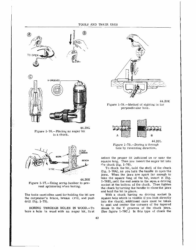
TOOLS AND THEIR USES
44.206 Figure I-76.-Placing an auger bit
in a chuck.
44.20H Figure l-77.-Using scrap lumber to pre-
vent splintering when boring.
The tools most often used for holding the bit are the carpenter’s brace, breast <i-ill, and push drill (fig. l-75).
BORING THROUGH HOLES IN WOOD.-To bore a hole in wood with an auger bit, first
42
44.20K Figure I-76.-Method of sighting in for
perpendicular hole.
44.2OL Figure I-79.-Boring a through
hole by reversing direction,
select the proper fit indicated on or near the square tang. Then you insert the auger bit into the chuck (fig. l-76).
To chuck the bit, hold the she!1 of the chuck (fig. l-76A), as you turn the handle to open the jaws. When the jaws are apart far enough to take the square tang of the bit, insert it (fig. l-76B),until the end seats in the squzue driving socket at the bottom of the chuck. Then tighten the chuck by turning the handle to close the jaws and hold the bit in place.
With a chuck having no driving socket (a square hole which is visible if you look directly into the chuck), additional care must be taken to seat and center the cmners of the tapered shank in the V grooves of the chuck jaws. (See figure l-76C.) In this type of chuck the
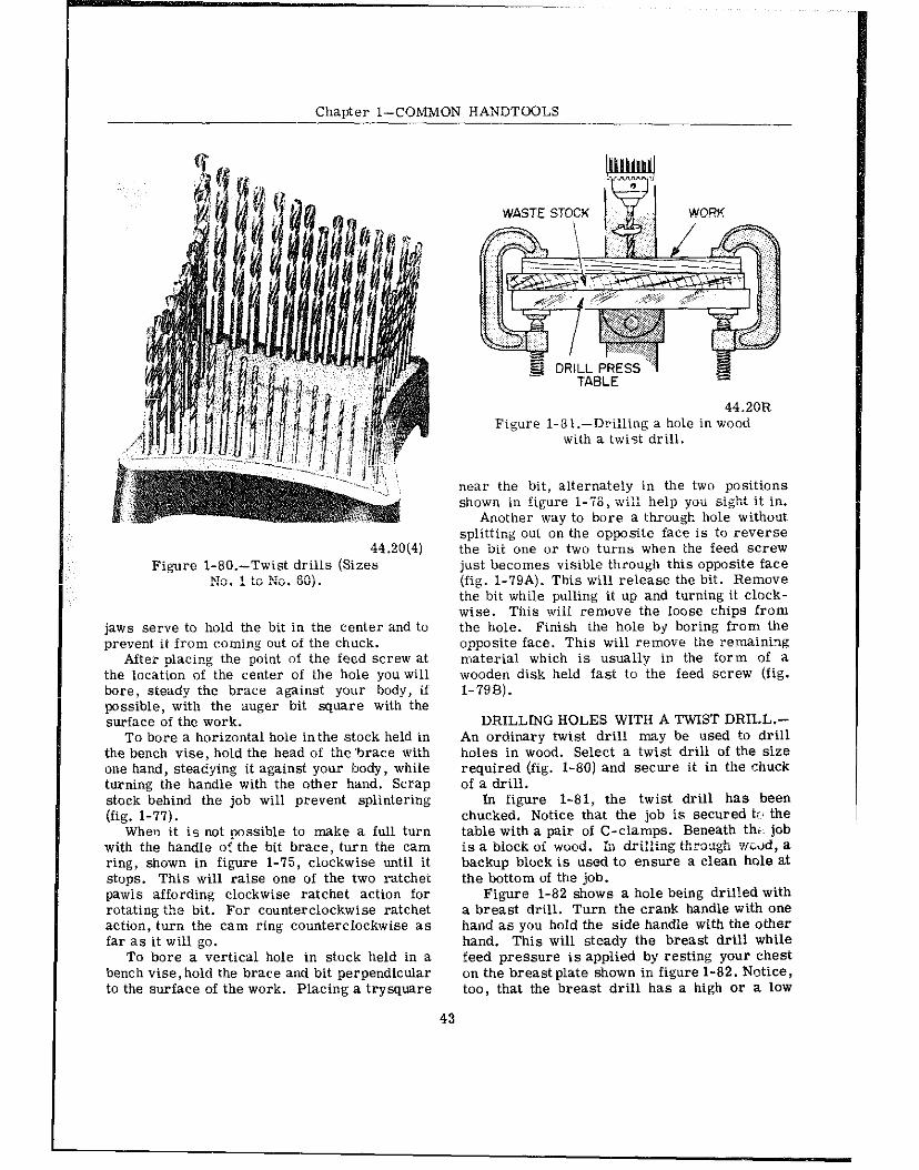
Chapter l-COMMON HANDTOOLS
44.20(4) Figure 1-80.-Twist drills (Sizes
No. 1 to so. 50).
jaws serve to hold the bit in the center and to prevent it from coming out of the chuck.
After olacipg the point of the feed screw at the location of the center of the hole you will bore, steady the brace against your body, if possible, with the auger bit square with the surface of the work.
To bore a horizontal hoie inthe stock held in the bench vise, hold the head of the ‘brace with one hand, ste+ing it against your body, while turning the handle with the other hand. Scrap stock behind the job will prevent splintering (fig. l-77).
When it is not possible to make a full turn with the handle of the bit brace, turn the cam ring, shown in figure l-75, clockwise until it stops. This will raise one of the two ratchet pawls affording clockwise ratchet action for rotating the bit. For counterclockwise ratchet action, turn the cam ring counterclockwise as far as it will go.
To bore a vertical hole in stock held in a bench vise, hold the brace and bit perpendicular to the surface of the work. Placing a trysquare
43
44.2OR Figure 1-81.-Drilling a hole in wood
with a twiSt drill.
near the bit, alternately in the two positions shown in figure l-78, wi:: help yoii ei&t it in.
Another way to bore a through hole without splitting out on the opposite face is to reverse the bii one or two turns when the feed screw just becomes visible through this opposite face (fig. I-79A). This will release the bit. Remove the bit while pulling it up and turning it clock- wise. This will remove the loose chips from the hole. Finish the hole by boring from the opposite face. This will remove the remaining material which is usually in the form of ZI wooden disk held fast to the feed screw (fig. l-798).
DRILLING HOLES WITH A TWIST DRILL.- An ordinary twist drill may be used to drill holes in wood. Select a twist drill of the size required (fig. l-80) and secure it in the chuck of a drill.
In figure 1-81, the twist drill has been chucked. Notice that the job is secured tc< the table with a pair of C-clamps. Beneath thb: job is a biock oi wood. h drilltug through wwd, a backup block is used to eneure a clean hole at the bottom of the job.
Figure 1-82 shows a hole being dril!ed with a breast drill. Turn the crank handle with one hand as you hold the side handle with the other hand. This will steady the breast drill while feed pressure is applied by resting your chest on the breast plate shown in figure l-82. Notice, too, that the breast drill has a high or a low

TOOLS AND THEiR USES
4.33A Figure I-82.-Drilling a hole with
a breast drill.
4.34A Figure 1-83.-Drilling a hole with
a hand drill.
B
44.116 Figure 1-84.-Push drill and drill point.
speed available, according to the setting of the speed selector nut. When driiling a horizontal hole, apply feed pressure by resting your body against the breast plate.
In drilling a horizontal hole with the hand drill shown in figure l-83, operate the crank with the right hand and with the left hand guide the drill by holding the handle which is opposite the chuck end of the drill.
DRILLING HOLESWITH A”PUSH” DRILL.- Figme l-84A shows the Stanley ‘Yankee” auto- matic drill which is often cal!ed a “push” drill.
44.111 Figure I-85.--Selecting a drill for
use in a push &ill.
This drill can be used to drill either horizontal or vertical holes when the accuracy of the right angle -with the work is not critical.
The drill point used in push drills (fig. l-84B) is a straight flute drill. Sharpen its point on the grinder and provide only sli@t clearance behind the cutting edge. It will drill holes in wood and other soft materials.
44

Chauter I-COMMON HANDTOOLS
44.118 Figure 1-86.-Drilling horizontal and
vertical holes with a push drill.
29.9B Figure l-87.-Tang and socket
wood chisels.
To select a drill for use in a push drill, hold the handle of the drill in one hand and release the magazine by turning the knurled screw as shown in figure l-85A. This will permit you to drop the magazine. Figure 1.85B, shows the drill magazine lowered to expose the drills from which the proper size can be selected.
To chuck the drill, loosen the chuck several turns and insert the drill as far as it will go. Turn ‘he dril! untii it seats inthe driving socket in the bottom of the chuck. Then tighten the chuck to hold the drill in place. (fig. l-850.
To drill a vertical hole with this drill (fig. l-86A), place the job on a flat surface and op- erate the push drill with alternate strokes up
45
BUTT CHISEL
Figure l-88.-Shapes of comnx of wood chisels.
and down. If it is necessary to hold place while it is being drilled, USI chanical means if you can. If you n job with your hand, grasp the mater possible from where the drill is drj
In drilling horizontal holes wi drill, as in figure l-8EB, secure vise. The back-and-forth strokes drill, advancing it into the work on stroke as the drilling proceeds. finger, extended along the body of 1 help guide the drilling at right a work.
WOOD CHISELS
A wood chisel is a steel tool wooden or plastic handle. It has a eled cutting edge on the end of the : blade. According to their construe may be divided into two general cla chisels, in which part of the chist handle, and SOCKET chisels,in whi enters into a part of the chisel (fig.
I the work in 3 some me- lust hold the ial as far as
the job in a I rotate the
the forward The index
ihe tool, will ngles to the
fitted with a
sses: TANG 31 enters the ch the handle

TOOLS AND THEIR USES
A socket chisel is designed for striking with a wooden mallet (never a steel hammer), while a tang chisel is designed for hand manipulation only.
Wood chisels are also dividedinto types, de- pending a~pon tboi; .vx-eights and thicknessrs, the shape or design of the blade, and the work they are intended to do.
The shapes of the more common types of woo:! cbtse:s are shown in figure l-86. The FIRMER chisel has a strong, rectangular- cross-section blade, designed for both heavy and light work. The blsde -Z the PARiKG chisei is relatively thin,and is beveled along the sides for the fine paring work. The BUTT chisel has a short blade,designed for workin hard-to-get- at places.
The butt chisel is commonly used for chisel- ing the GAINS (rectangular depressions) for the BUTT hinges on doors; hence the name. The MORTISING chisel is similar to a socket firmer but has a narrow blade, designed for chiseling out the deep, narrow MORTISES for mortise- and-tenon joints. This work requires a good deal of levering out of chips; consequently, the mortising chisel is made extra thick in the shaft to prevent breaking.
A FRAMING chisel is shaped like a firmer chisel, but has a very heavy, strong blade de- signed for work in rough carpentry.
A wood chisel should always be held with the flat side or back of the chisel against the work for smoothing and finishing cuts. Whenever possible, it should not be pushed straight through an opening, but should be moved lat- erally at the same time that it is pushed for- ward. This method ensures a shearing cut, which with care,will produce a smooth andeven surface even when the work is cross-grained. On rough work, use a hammer or mallet to drive the socket-type chisel.
On fine work, use your hand as the driving power on tang-type chisels. For rough cuts, the bevel edge of the chisel is held against the work. Whenever possible, other tools such as saws and planes should be used to remove as much of the waste as possible, and the chisel used for finishir,g purposes only.
These are a few basic precautions that you shou!d observe at a:i times when using a chisel.
a. Seewe work so that it cannot move. b. Kesp both hands back of the cutting
edge at all times.
c. Do not start a cut on a guideline. Start slightly away from it, so that there is a small amount of material tobe removed by the finish- ing cuts.
d. When starting a cut; always chisel away from the guideline toward the waste wood, so that no splitting will occur at the edge.
e. Never cut towards yourself with a chiser.
f. Make the shavings thin, especially when finishing.
g. Examine the grain of the wood to see which way it runs. Cut with the grain. This severs the fibers and leaves the wood smooth. .Zutting against the grain splits the wood and leaves it rough. This type of cut cannot be controlled.
R&ITC”ET mJLl SPIRAL DRIVER
l.l4(44B)A Figure 1-89.-Screwdrivers.
46

Chapter l-COMMON WANDTOOLS
SCREWDRNERS
A screwdriver is one of the most basic of basic handtools. It is also the most frequently abused of all handtools. It is designed for one function only-to drive and remove screws. A screwdriver should not be used as a pry bar, a scraper, a chisel, or a punch.
STANDARD
‘Inere are three main parts to a standard screwdriver. The portion you grip is called the handle, the steei portion extending from ihe handle is the shank, and the end which fits into the screw is called the blade (fig. l-89).
The rieei shank is designed to withstand considerable twisting force in proportion to its size, and the tip oi the blade is hardened to keep it from wearing.
Standard screwdrivers are classified by size, according to th.e co.x+iued leng?h of the shank and blade. The most common sizes range in length from 2 l/2 in. to 12 in. There are may screivdri.vers smaller and some larger for special purposes. The diameter of the shank, and the width and thickness of the blade are generally proportionate to the length, but again there are special screwdrivers with long thin shanks, short thick shanks, and extra wide or extra narrow blades.
Screwdriver handles may be wood, plastic, or metal. When metal handles ai-e used, there is usually a wooden hand grip placed on each side of the handle. In soliie types of wood- or plastic-handled screwdrivers the shank extends *p;“$ the hznd&, *.“.iic i;; &bers sic *barn enters the handle onlya short way and is pinned to the handle. For heavy work, special types of screwdrivers are made with a square shank. They are designed this way so that they may be gripped with a wrench, but this is the only kind on which a wrench should be used.
When using a screwdriver it is important to select the proper size so that the blade fits the screw slot properly. This prevents burring the dot and reduces the farce required to hold the driver in the slot. Keep the shank perpendicu- lar to the c-crew head (fig. l-90).
RECESSED
Recessed screws are now available in vari- ous shapes. They have a cavity formed in the
l.l4(44B)B Figure I-90.-Positioning screwdrivers.
REED AND, PRlNCE HEA
0 + Tom-SET PHlLLlFS HEAJ SCREI HE”” 29.123(44B)
Figure 1-31.-Comparison of Phillips, Reed, and Prince and Torq-Set screwheads.
(A) PHILLIPS
(8) REEDAND PRINCE
l.l4(44B)C Figure 1-92.-Matching cross-slot screws
and drivers.
head and require a specially shaped .screw- driver. The clutch tip (fig. I-89) is one shape, but the more common include the Phillips, Reed and Prince, aad newer Torq-Set types (fig. 1-91). The most common type found is the
47

TOOLS AND THEIR USES
I
Phillips head screw. This requires a Phillips- iype screwdriver (fig. l-89).
Phillips Screwdriver
The head of a Phillips-type screw has a four-way slot into which the screwdriver fits. This prever.ts the screwdriver from slipping. Three standard sized Phillips screwdrivers handle a wide range of screw sizes. Their abil- ity to hold helps to prevent damaging the slots or the work surrounding the screw. It is a poor practice to try to use a standard screwdriver on a Phillips screw because both the tool and screw slot will be damaged.
Reed and Prince Screwdriver
Reedand Prince screwdrivers are e inter- changeable with Phillips screwdrivers. There- fore,always use aReed and Prince screwdriver with Reed and Prince screws and a Phillips screwdriver with Phillips screws, or a ruined tool or ruined screwhead will result.
How do you distinguish betweenthese similar screwdrivers? Refer to figure l-92.
ThePhillips scre-wdriverbaaab=;i: Se-degree flukes and a blunt end, while tine Reed and Prince has 4%degree flukes and a sharper, Finted end. The Phillips screw has beveled walls between the slots; the Reed and Prince, straight, pointed walls. In addition, the Phillips screw slot is not as deep as the Reed and Prixe slot.
Additional ways to identify the right screw- driver are as follows:
1. If it tenda to sttnd up unassisted when the point is put in the head of a vertical screw, it is probably the proper one.
2. The outline of the end of a Reed and Prince screwdriver is approximately a right angle, as seen in the illustration.
3. In general, Reed and Prince screws are used for airframe structural applications,while Phillips screws are found most often in com- ponent assemblies.
“Torq-Set” Screws
“Torq-Set” machine screwe (offset cross- .?lot drive) have recently begun to appear in new equipment. The main advantage of the newer type is that more torque can be applied to its head while tightening or loosening than
any other screw of comparable size and mate- rial without damaging the head of the screw.
Torq-Set machine screws are siniilar in appearance to the more familiar Phillips ma- chine screws.
Since a Phillips driver could easily damage a Torq-Set screwhead, making it difficult if not impossible to remove the screw even if the proper tool is later used, maintenance person- nel shnu!d be alert to the differences (fig. I-91) and ensure that the proper tool is used.
OFFSET SCREWDRIVERS.-Anoffset ecrew- driver (fig. 1-89) may be used where there is not sufficient vertical space for a standard or recessed screwdriver. Offset screwdrivers are constructed with one blade forged in line and another blade forged at right angles to the shank handle. Both blades are bent 90 degrees to the shank handle. By alternating ends, most screws can be seated or loosened even when the swinging space is very restricted. Offset screwdrivers are made for both standard and recessed head screws.
RATCHET SCREWDRIVER
For fast easy work the ratchet screwdriver (fig. l-89), is extremely convenient, as it cafi be used one-handed and does not require the bit to be lifted out of the slot after each turn. It may be fitted with either a standard type bit or a special bit for recessed heads. The ratchet screwdriver ie most commonly used by the woodworker for driving screws in soft wood.
SAFETY
l Never use a screwdriver to check an electrical circuit.
l Never try to turn a screwdriver with a pair of pliers.
a Do not hold work in your hand while using a screwdriver-if the point slips it can cause a bad cut. Hold the work in a vise, with a clamp, or on a solid surface. If that is impossiiiie, you will always be safe if you follow this rule: NEVER GET ANY PART OF YOUR BODY IN FRONT OF THE SCREWDRIVER BLADE TIP. That is a good eafety rule for any sharp or pointed tool.
fJLIERS
Pliers are made in many styles and sizes and are used to perform many different
48

Chauter l-COMMON HANDTOOLS
Figure l-
1.21.4A Figure I-94.-Slipjoint p!iers.
operations. Pliers are used for cutting pur- poses as weli as hoiding and gripping small articles in situations where it may be incon- venient or impossible to use hands. Figure 1-93 shows several different kinds.
The combination pliers are handyfor holding or bending flat or round stock. The long-nosed pliers are less rugged, and break easily if you use them on heavy jobs. Long-nosed pliers commonly called needle-nose pliers are espe- cially useful for holding small objects in tight places and for making delicate adjustments. The round-nosed kind are handy when you need to crimp sheet metal or form a loop in a wire, The diagonal cutting pliers, commonly called “diagonals” or “dikes,“are designed for cutting wire and cotter pins close to a flat surface and are especially useful in the electronic and elec- trical fields. The duckbill pliers are used ex- tensively in aviation areas.
Here are two important roles for using pliers:
.93.-Pliers. l.Zl(44B)A
1.2f.4B Figure I-95.-Slipjoint
combination pliers.
1. Do not make pliers work beyond their capacity. The long-nosed kind are especially delicate. It is easy to spring or break them, or nick their edges. After that, they are practi- cally useless.
2. Do not use pliers to turn nuts. In just a few seconds, a pair of pliers can damage a nut. Pliers must pc& be substituted for wrenches.
SLIP- JOINT PLIERS
Slip-joint pliers (fig. l-94) are pliers -with straight, serrated (grooved) jaws, and the screw cr pivot with which the jaws are fastened to- gether may be moved to either of two pos;‘.ions, in order to grasp small- or large-sized ob- jects better.
To soread the jaws of slip-joint pli?rS, first spread the ends of the handles apart as far 2s possible. The slip- joint, or pivot, will now move to the open position. To close, again spread the handles as far as possible, then push the joint back into the closed position.
49
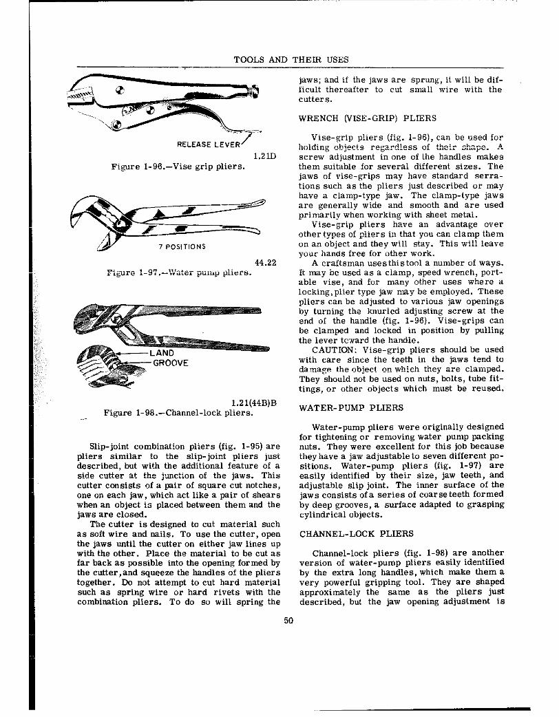
TOOLS AND THEIR USES
RELEASE LEVER /
1.21D Figure l-g&-Vise grip pliers.
l.Zl(44B)B Figure 1-98.-Channel-lock pliers. --
Slip-joint combination pliers (fig. l-95) are pliers similar to the slip-joint pliers just described, but with the additional feature of a side alttter at the junction of the jaws. This cutter consists of a pair of square cut notches, one on each jaw, which act like a pair of shears when an object is placed between them and the jaws are closed.
The cutter is designed to cut material such as soft wire and nails. To use the cutter, open the jaws until the cutter on either jaw lines up with the other. Place the material to be cut as far back as possible into the opening formed by the cutter,and squeeze the handles of the pliers together. Do not attempt to cut hard material such as spring wire or hard rivets with the combiration pliers. To do so will spring the
jaws; and if the jaws are sprung, it will be dif- ficult thereafter to cut small wire with the cutters.
WRENCH (VISE-GRIP) PLIERS
Vise-grip p!iers (fig. l-96), can be used for ho!ding cbjects regard!ess of their sh”pe. A screw adjustment in one of the handles makes them suitable for several different sizes. The jaws of vise-grips may have standard serra- tione such as the pliers just described or may have a clamp-type jaw. The clamp-type jaws are generally wide and smooth and are used primarily when working with sheet metai.
Vise-grip pliers have an advantage over other types of pliers in that you can clamp them on an object and they will stay. This wil! leave your hands free for other work.
A craftsman uses this tool a number of ways. it may be used as a clamp, speed wrench, port- able vise, and for many other uses where a locking,plier type jaw may be employed. These pliers can be adjusted to various jaw openings by turning the knurled adjusting screw at the end of the handle (fig. l-96). Vise-grips can be clamped and locked in position by pulling the lever tc-.vard the handie.
CAUTION: Vise-grip pliers should be used with care since the teeth in the jaws tend to damage the object on which they zre c:anped. They should not be used on nuts, bolts, tube fit- tings, or other objects which must be reused.
WATER-PUMP PLIERS
Water-pump pliers were originally designed for tightening or removing water pump packing nuts. They were excellent for this job because they have a jaw adjustable to seven different pa- sitions. Water-pump pliers (fig. l-97) are easily identified by their size, jaw teeth, and adjustable slip joint. The inner surface of th? jaws consists of a series of coarse teeth formed by deep grooves, a surface adapted to grasping cylindrical objects.
CHANNEL-LOCK PLIERS
Channel-lock pliers (fig. l-98) are another version of water-pump pliers easily identified by the extra long handles, which make them 2 very powerful gripping tool. They are shaped approximately the same as the pliers just described, but the jaw opening adjustment iS
50

Chapter l-COMMON HANDTOOLS
effected differently. Channel-lock pliers have grooves on one jaw and lands on the other. The adjustment is effected by changing the position of the grooves and lands. The Channel-lock pliers are less likely to slip from the adjust- ment setting when gripping a” object. The channel-lock pliers will on!y be used where it is impossible to use a more adapted wrench or holding device. Many nuts and bolts and sur- rounding parts have been damaged by improper “se of channel-lock pliers.
DIAGONAL PLIERS
Diagonal cutting pliers (fig. l-93) are used for cutting small, light material, such as wire and cotter pins in areas which are inaccessible to the larger cutting tools. Also, since they are designed for r?rtting only, larger objects can be cut than with the slip-joint pliers.
As the cutting edges are diagonally offset approximately 15 degrees, diagotxxl pliers are adapted to cutting small objects flush with a surface. The inner jaw surface is a diagonal straight cutting edge. Diagonal pliers should never be nsed to hold objects, because they ex- ert a greater shearing force than other types of pliers of a similar size. The sizes of the di- agonal cutting pliers are designated by the overall length of the pliers.
SIDE-CUTTING PLIERS
Side-cutting pliers (sidecutters) are prin- cipally used for holding, bending, and cutting thin materials or small gage wire. Sidecutters vary in size and are designated by their overall length. The jaws are hollowed out on one side just forward of the pivot point of the pliers. Opposite the hollowed out portion of the jaws are the cutting edges (fig. l-93).
When holding or bending light metal surfaces, the jaw tips are used to grasp the object. When holding wire grasp it as “ear one end as pos- sible because the jaws wiil mar the wire. To cut small diameter wire the side cutting edge of the jaws “ear the pivot is used. Never use sidecurters to grasp iarge objects, tighten nuts, or bend heavy gage metal, since such operations will spring the jaws.
Sidecutters are often called electrician oi- lineman pliers. They are used extensively for stripping insulation from wire and for twisting wire when making a splice.
51
l.Zl(44B)C Figure 1-99.-Pliers. (A) Duckbill;
(B) needle nose; and (C) wire twister.
DUCKBILL PLIERS
Duckbill pliers (fig. l-99A), have long wide jaws and slender handles. Duckbills are used in confined areas where the fingers cannot be used. The jaw faces of the pliers are scored to aid in holding a” item securely. Duckbills are ideal for twisting the safetywire used in secur- ing nuts, bolts, and screws.
NEEDLE-NOSE PLIERS
Needle-nose pliers (fig. 1-99B), are used in the .sa~le manner as dockbill pliers. However, there is a difference in the design of the jaws. Needle-nose jaws are tapered to a point which makes them adapted to installing and removing small cotter pins. They have serrations at the nose end and a side cltiier “ear the throat. Needle-nose pliers may be used to hold small items steady, to cut and bend safety wire, or to do numerous other jobs which are too intricate or too difficult to be done by hand alone.
NOTE: Duckbil! and needle-nose pliers are especially delicate. Care should be exercised when using these pliers to prevent springing, breaking, or chipping the jaws. Once these pliers are damaged, they are practically useless.
WIRE-TWISTER PLIERS
Wire-twister pliers (fig. 1-99C), are three- way pliers, which hold, twist, and cut. They

TOOLS AND THEIR USES
HAND SCREW
Y CPERA.T!NG
29.llA Figure l-102.-C-Clamp and handscrew clamp.
44.35 Figure I-103.-Shapes of sharpening stones and oilstones.
open the crimped portion of the head and re- nave the heady from thr ball end of the screw.
body between the jaws OP between one jaw and the work.
Replace with a new head and crimp.
SAFETY PRECAUTIONS
When holding heavy work in a vise, place a block of wood under the work as a prop to pre- vent it from sliding down and falling on your foot.
When closing the jaw of a vise or clamp, avoid getting any portion of your hands OP
Do not open the jaws of a vise beyond their capacity, as the movable jaw will drop off,
54

Chapter l-COMMON HANDTOOLS
causing personal injury and possible damage to the jaw.
SHARPENING STONES
Sharpening stones are divided into two groups, natural and artificial. Some of the natural stones are oil treated during and after the manufacturing processes. The stones that are oil treated are sometimes called oilstones. Artificial stones are normally m?.de of silicone carbide “1‘ aluminum oxide. Natural stones have very fine grains and are excellent for putting razorlike edges on fine cutting tools. Mosl sharpening stones have one coarse axI one fine face. Some of these stones are mounted, and the working face of some of the sharpening stones is a combination of c”arse and fine grains. Stones are available in a vareity of shapes, as shown in figure l-103.
A fine cutting oil is generally used with most artificial sharpening stones; however, other lubricats such as kerosene may be used. When a tool has beer. sharpened on z grinder or grindstone, there is usually a wire edge “I’ a feather edge left by the c”arse wheel. The sharpening stones are used to hone this wire or feather edge off the cutting edge of the tool. Do not attempt to do a honing job with the wrong stone. Use a ccarse stone to sharpen large and very dull or nicked tools. Use a medium grain stone to sharpen tools not requiring a finished edge, such as tools for working soft wood,cloth, leather, and rubber. Use a fine stone and 2.n oilstone to sharpen and hone tools requiring a razorlike edge.
Prevent glazing of sharpening stones by ap- plying a light oil during the use of the stone. Wipe the stone clean with wiping cloth or cotton waste after each use. If stone becomes glazed or gummed up, clean with aqueous ammonia OF drycleaning solvent. If necessary, sc”ur with aluminum oxide abrasive cloth “I‘ flint paper attached to a flat block.
At times, stones will become uneven from improper use. True the uneven surfaces on an old grinding wheel or on a grindstone. Another method of truing the surface is to lap it with a block of cast iron or other hard snzterial cov- ered with a waterproof abrasive paper, dipping the stone in water at regular intervals and con- tinuing the lapping until the stone is true.
Stones must be carefully stored in boxes or on special racks when not in use. Never lay them down on uneven surfaces “I’ place them
55
Z9.9N Figure 1-104.-Sharpening a
woodworker’s chisel.
where they may be knocked Iff a table or bench, or where heavy objects can fall on them. Do not stwe in a hot place.
SHARPENING A WOOD CHISEL
To sharpen a wood chisel with a sharpening stone, use a comtn”n oilstone that has coarse grit on one side and fine grit on the other (fig. l-104). Make sure the stone is firmly held so that it cannot move. Cover the stone with a light machine oil so that the fine particles of steel ground off will float and thus prevent the stone from clogging.
Hold the chisel in one hand with the bevel flat against the coarse side of the stone. Use the fingers of your other hand to steady the chisel and hold it down against the stone. Using smooth even strokes, rub the chisel back and forth parallel to the surface of the stone (fig. 5-18). The entire surface of the stone should be used to avoid wearing a hollow in the center of the stone. Do not rock the blade. The angle of the

TOOLS AND THEIR USES
44.137 Figure 1-105.-Sharpening a pocket knife.
blade wi’h the stone must remain constant dur- ing the whetting process.
After a few strokes, a burr, wire edge, or feather edge is produced. To remove tine burr, first take a few strokes with the flat side of the chisel held flat on the fine grit side of the stone. Be careful not to raise the chisel even slightly; avoid putting the slightest bevel on the flat side, for then the chisel must be ground until the bevel is removed.
After whetting the flat side on the fine grit side of the stone, turn the chisel over and place the bevel side down and hold it at the Same angle as used when whetting on the coarse side of the stone. Take two or three light strokes to remove the burr.
To test the sharpness of the cutting edge, hold ihe chisel where a good light will shine on the cutting edge. A keen edge does not reflect iight in any position. If there are no shiny or white spots it is a good edge.
SHARPENING A POCKET KNIFE
Pocket knives may be sharpened on a me- diun, 01 fine grade sharpening stone with a few drops of oil spread on the surface. Hold the handle of the knife in one hand and place the blade across the stone. Press dwm with the fingers of the other hand and stroke the blade following a circular motion as shown in figure l-105. After several strokes, reverse the blade and stroke the opposite side,following the same type of motion. Use a light even pres- sure. 4 thin blade overheats quickly and can
56
44.210 Figure 1-106.-Knives.
lose its temper. The wire edge or burr that way be :eft on a knife blade after whetting may be removed by stropping both aides a a soft wood block, canvas or leather.
MISCELLANEOUS TOOLS
Tools described in this section may be en- countered at some time in your Navy career. They may not necessarily be found in any par- ticular toolkit but may be stored in a central toolroom, to be checked out when needed. This section of the text will give you Some tips on their nomenclature, where and how they can be used, and some safety precautions to be ob- served when using these tools.
KNIVES
Most knives are used to cut, pare, and trim wood, leather, rubber and other similar mate- rials. The types you will probably encounter most frequently are the shop knife,pocket knife, and the putty knife (fig. I-iO6).
The shop knife can be used to cut cardboard, linoleum, and paper. It has an aluminum han- dle and is furnishedwith interchangeable blades stored in the 5-inch handle.
Pocket knives are used for light cutting, sharpening pencils, cutting strings, etc. They are unsuited for heavy work. Multi-purpose knives have an assortment of blades designed for forcing holes, driving screws and opening cans, as well as cutting. The blades are hinged and should be contained within the case when

Chapter l-COMMON HANDTOOLS
not in use. They are spring loaded to keep them firmly in place when open or closed.
A putty knife is used for applying putty to window Sash when setting in panes of glass. The blade has a wide square paint available in different lengths and widths.
Safety with knives is essential. Do not use knives larger than can be safely handled. Use knives only for the purpose for which they were designed. Always cut away from your body. Do not carry open knives in your pocket or leave them where they may come into contact with OP cauee injury to others. Put knives away carefully after use to protect sharp cutting edges from coGacting other hard objects.
MECHANICAL FINGERS
Small articles which have fallen into places where they cannot be reached by hand may be retrieved with the mechanical fingers. This tool is also used when starting nuts or bolts in difficult areas. The mechanical fingers, shown in figure l-107 have a tube containing flat springs which extend from the end of the tube to form. clawlike fingers, much like the screw holder. The springs are attached to a rod that extends from the outer end of the tube. A plate is attached to the end of the tube, and a similar plate to be pressed by the thumb is attached to the end of the rod. A coil spring placed around the rod between the two plates holds them apart and retracts rhe fingers into the tube. With the bottom plate grasped between the fingers and enough thumb pressure applied to the top plate to compress the spring, the tool fingers extend from the tube in a grasping position. When the thumb pressure is released, the tool fingers retract into the tube as far as the object they hold will allow. Thus, enough pressure is ap- plied on the object to hold it securely. Some mechanical fingers have a flexible end on the tube to permit their use in close quarters or around obstructions (fig. l- 107).
NOTE: Mechanical fingers should not be used as a substitute for wrenches or pliers. The fingers are made of thin sheet metal or spring wire and can be easily damaged by overloading.
Flashlight
Each toolbox should have a standard Navy vaporproof two-cell flashlight. The flashlight
EXTENDED POSITION RETRACTED POSITION
44.211 Fig~crre l-lo:.-Mechanical fingers.
is used constantly during all phases of main- tenance. Installed in both ends of the flashlight are rubber seals which keep out all vapors. The flashlight should be inspected periodically for the installation of these seals, the spare bulb, and colored filters which are contained in the end cap. NQTE: Do not throw away the filters; they will be necessary during night operations.

TOOLS AND THEM USES
44.212 Figure I-108.-Adjustable inspection
m,rror.
!JJSPECTION MIRROR
There are several types of inspection mir- rors available for use in maintenance. The mirror is issued in a variety of sizes and may be round or rectangular. The mirror is con- nected to the end of a rod and may be fixed or adjustable (fig. I-108).
The inspection mirror aids in making de- tailed inspection where the human eye cannot directly see the inspection area. By angling the mirror. and with the aid of a flashlight, it is possible to inspect most required areas. A late
model inspection mirror features a built-in light to aid in vieming those dark places where use of a flashlight is not convenient.
PERSONAL SAFETY EQUIPMENT
To protect, you from danger, protective equipment such as safety shoes, goggles, hard hats and gloves are issued. The use of this equipment is mandatory on certain jobs. Their Iuse is a MUST and there is no question about that. Be em-e to USE THEM on any job WHERE they are REQUIRED. They can protect you irom a lot. of harm.
SAFETY SHOES
Some safety shoes are designed to limit damage to your toes from fallins objects. A steel plate is placed in the toe area of such shoes so that ywr toes are not crushed if an object impacts there.
Other safety shoes are designed for we where danger from sparking could cauee an explosion. Such danger is minimized by elimi- nation of all metallic nails and eyelets and the use of soles which do not cause static electricity.
Figure l-109.-Eye protection devices.
58

Chapter l-COMMON HANDTOOLS
29.201 Figure I-ilO.-Gas and electric-arc
welding gauntlet gloves.
SAFETY STRA
29.239.1 Figure l-111.~Safety equipment.
GOGGLES
Proper eye protection is the utmost im- portance for all personnel. Eye protection is necessary because of hazards posed by infrared and ultraviolet radiation, or by flying objects such as sparks, globules of molter? metal, or chipped concrete and wood, etc. These hazards are everpresent during welding, cutting, solder- ing, chipping, grinding and a variety of other operations. It is IMPERATIVE for you to use eye protection devices such as helmets, hand- shieids and goggies (fig. l-109) during eye- hazard operations.
Appropriate use of goggles will limit eye hazards. Some goggles have plastic windows which resist shattering upon impact. @hers
59
26.203 Figure 1-112.-Hardhat.
are designed to limit harmful infrared and ul- traviolet radiation from arcs or flames by ap- propriate filter lenses.
&member, eye damage can be excruciatingly painfui. PROTECT YOUR EYES.
GLOY ES
Use gloves whenever you are required to handle rough, scaly, or splintery objects. Spe- cial flameproof gloves are designed for gas and electric welding, to limit danger and damage from sparks and other hot flying objects (fig. l-110). Personnel in the electrical fields are usuallv required to wear insulating rubber gloves.
Be sure to follow all regulations prescribed for the use of gloves. Gloves must not be worn around rotating machinery unless sharp or rough material is being handled. If such is the case, EXTREME CARE SHOULD BE EXER- CISED to prevent the gloves from being caught in the machinery.
SAFETY BELTS AND STRAPS
The “safety ;trap” and “body belt” shown in figure l-111 are what might be called your ex- tra ha.nds when you work aloft. The body belt,

TOOLS AND THEIR USES
strapped around your waist contains various pockets for small tools. The safety strap is a leather or neoprene impregnatednylon belt with a tongue-type buckle at each end. While you are climbing you will have the safety strap hanging by both ends from the left ring (called a “D” ring because of its shape) on the body belt. When you are at working position, you unsnap one end of the safety strap, pass it around the supporting structure so there is no danger of its slipping (at least 18 inches from the top of the part on which it is fastened), and hook it to the right “D” ring on the body belt.
The safety strap must he placed around a part of the structure which is of sufficient strength to sustain a man’s weight and his equipment, and must rest flat against the sup- face without twists or turns. It must not be placed around any part of a structure which is being removed. Men climbing poles at shore stations must be sure to place the straps he- neath arms and braces of the poles, wherever possible.
Before placing your weight on the strap, de- termine VISUALLY that the snap and “D” ring are properly engaged. Do not rely on the “click” of the snap-tongue as an indication the fastening is secure.
The body belt and safety strap require in- spection before use. Look for loose or broken rivets, cracks, cuts, nicks, tears or wear in leather, broken or otherwise defective buckles, such as enlarged tongue-holes, defects in safety-belt snap hooks and body belt “D” rings. If you discowr any of these or other defects, turn in your equipment and replace it.
Perform maintenance periodically in ae- cordance with applicable procedures. Remem- ber that leather and nylon belts are treated in different manners.
PROTECTIVE HELMETS
Protective helmets (hard hats) come in a variety of shapes. They may be made of tough
polyethylene or polycarbonate, one of the toughest hat materials yet developed. Many a man has had his life saved because he wore a protectw? hat (fig. 1-112). When a falling object stru?k the hat the shock-absorbing sus- pension capabilities minimized damage to the mair’s head.
Regular !mrd hats are required to have a degree of insulation resistance such that per- sonnel, other than electrical, may be protected from accidental head contacts with electrical circuits and equipment at comparatively low voltages (less than 2200 volts).
Electrical workers requiring head protec- tion incidental to their duties or to the working environment, particularly those engaged in transmission or distribution line installation and repair must wear insulating safety helmets or all-purpose protective helmets which must be capable of withstanding 20,000 volt minimum proof-tests.
BUILT-IN SAFETY EQUIPMENT
In previous paragraphs we discussed a va- riety of safety equipment furnished by the Navy. Don’t forget about your own built-in safety equipment, however.
You have EYES to see danger, EkRS to hear warnings, FEET to get away, BRAINS to know when danger is near, HANDS to help you re- move or correct unsafe conditions,and aVOICE to warn your shipmates of unsafe acts. Use this safety equipment advantageously to limit accidents.
Above all, remember your ABC’s.
ALWAYS
BE
CAREFUL
60

CHAPTER 2
c P T 1s
Power tools are so commonplace in the Navy that men in all ratings use some power tools at one time or another. This chapter of the text will be dewted to the more common types of electric and air-driven power tools and equip- ment. Upon completion, you should be able to identify them, discuss applicable safety meas- ures, and describe the general operating prac- tices and care of these tools.
SAFETY
Safe practices in the use of power tools can- not be overemphasized. There are several g:cneral safety measures to observe in operat- ing or maintaining power equipment.
e First of all, never operate power equip- ment unless you are thoroughly familiar with its controls and operating procedures. When in doubt, consult the appropriate operating in- struction or ask someone who knows.
e All portable tools should be inspected be- fore use to see that they are clean and in a proper state of repair.
a Have ample illumination. If extension lights are required, ensure that a light guard is provided (fig. Z-1).
e Before a power tool is connected to a source of paver (electricity, air, etc.), BE SURE that the switch onthe tool is in the “OFF” position.
e When operating a power tool, give it your FULL and UNDIVIDED ATTENTION.
@ Keep all safety guards in position and use safety shields or goggles when necessary.
e Fasten all loose sleeves and aprons. . DO NOT DISTRACT OR IN ANY WAY
DISTURB another man while he is operating a power tool.
e Never try to clear jammed machinery un- less you remove the source of power first.
e After using a power tool, turn off the paver, rr?move the power source, wait for all rotation of the tool to stop, a,,d then clean the tool. Remove all waste and scraps from the
work area and stow the tool in its assigned location.
. Never plug the power cord of a portable electric tool into an electrical power source before ensuring that the source has the voltage and type of current (alternating or direct) called for on the nameplate of the tool.
0 If an extension cord is required, always connect the cord of a portable electric power tool into the extension cord before the exten- sion cord is inserted into a convenience outlet (fig. Z-2). Always unplug the extension cord from the receptacle before the cord of the port- able power tool is unplugged from the extension cord. (The extension cord and the power cord can each be no longer than 25 feet in length. Extra extension cords should be limited, wher- ever possible, to maintain allowable resistance to ground.)
Figure 2-l.-Safety poster. 40.67(67B)A
61

TOOLS AND THEIR USES
ORREST PLUG!
SAFETY GROUND
PIN
MAKE CERTAIN THAT THE TOOLS YOU USE HAVE A SAFETY PLUG AND CORD WITH INTEGRAL GROUNDING CONDUCTOR.
Figure 2-2.--Grounding plugs and convenience outlet. 40.67(67C)*:5.13
. Be sure to use a grounded plug and 3- ~:ziuctor cord. Figure 2-2 shows a perma-
nentlymolded type of groundedplugand also one used ior replacement purposes.
The purpose of the properly grounded con- ductor in the Y-conductor cord is to minimize the possibility of electrical shock. The end of the ~roundingconductor within the tool or equip- ment is connected to ihe metal housing by the manufacturer, and the other end is connected to the grounding blade or pin of the grounded plug. in this manner, the grounding conductor simulates the mounting bolts of permanent equipment: namely, it joins the metal case of portable electric equipment to the metal of the ship’s hull.
One exception to the use of 3-conductor grounded cord concerns plastic-cased tools (drills, sanders. grinders, etc.) that have been developed to eliminate the risk of electric shock. In these tools the shafts and chucks are isolated electrically from the drive motors. DO NOT replace the two-conductor cable on plastic- cased tools with 3.conductor cable IF the plastic-cased tool has an informationplate on it stating that “grounding is not required”!
. Be sure that power cords do not come in contact with sharp objects. The cords should not be allowed to kink, nor should they be ai- lowed to come in contact with oil, i rease, hot surfaces, or chemicals.
. When cords are damayed, ti:ti should be replaced.
. Portable cables should be of sufficient length that they will not be subjected to longi- tudinal stresses or need to be pulled taut to make connections.
a Electrical portable cables should be checked frequently while in service to detect unusual heating. Any cable which feels more than comfortably warm to the bare hand placed outside the insulation should be checked ini- mediately for overloading by competent electri- cal personnel.
. See that all cables are positioned so that they will not constitute tripping hazards.
. Electricity must be treated with respect and handled properly (fig. 2-3). If water ex- ists anywhere in the vicinity of energized equipment-be especially cautious, and wher- ever possible, deenergize the equipment.
. Always remember:
1. ELECTRICITY strikes without warning. 2. Every electrical circuit is a POTEN-
TIAL SOURCE OF DANGER and MUST BE TREATED AS SUCH.
3. Make no electrical repairs yourself unless you are qualified to do so.
62

Chaoter Z-COMMON POWER TOOLS
40.67.3(111A)
Figure 2-3.-Know what you are doing.
4. Sparkingelectric tools should never be used in places where flammable gases or liquids or exposed explosives are present. Pneumatic tools are used in these areas.
5. The power shotid always be discon- nected before accessories on tools are changed.
e Shipboardconditions are particularly con- dilcive to electric shock possibilities because the body may contact the ship’s metal struc- ture. Extra care is therefore needed, espe- cially when body resistance may be low because 3f perspiration or damp clothing. Insulate your- self from ground by means of insulating ma- teria! covering any adjacent grounded metal with which you might come into contact. Suit- able materials include dry wood, dry canvas, dry phenolic materia!, sfveial thicknesses of dry paper, or rubber mats. ALWAYS RETORT ANY SHOCK RECEIVED from electrical equip- ment. Minor shocks often lead to fatal shocks later on.
PORTABLE ELECTRIC POWER TOOLS
Portable power tools are tools that can be moved from place to place. Some of the most
MOTCF .W&S#NG TC,GGlR
4.35A
Figure Z-4.-l/4-inch portable electric drill.
common portable power tools that you will use in theNavy are electricallypowered and include drills, sanders, grinders and saws.
DRILLS
The portable electric drill (fig. 2-4) is prob- ably the most frequently used power tool in the Navy. Although it is especially designed for drilling holes, by adding various accessories you can adapt it for different jobs. Sanding, sawing, buffing, polishing, screw-driving, wire brushing,and paint mixing are examples of poS- sible uses.
Portable electric drills commonly used in the Navy have capacities for drilling holes in steel from l/16 inch u? to 1 inch in diameter. The sizes of portable electric drills are classi- fied by the maximum size straight shank drill it will hold. That is, a l/4 inch electric drill will hold a straight shank dri!!~xp tc ar.d in- cluding l/4 inch.
The revolutions per minute @pm) and power the drill will deliver are most important when choosing a drill for a job. You will find that the speed of the drill motor decreases with an in- crease in size, primarily because the larger units are designed to turn larger cutting tools or to drill in heavy materials, and both these factors require slower speed.
If you are going to do heavy work, such as drilling in masonry or steel, then you would probably need to use a drill with a 3/E or l/2 inch capacity. If most of your drilling will be forming holes in wood or small holes in sheet metal. then a l/4-inch drill will probably be adequate.
The chuck is the clamping device into which the drill is inserted. Nearly all electric drills
63

TOOLS AND THEIR USES
44.46
Figure 2-5.-Three jaw chuck and chuck key.
DATA PLATE \
44.49x Figure 2-6.-Portable electric sander.
are equipped with a three-jaw chuck. Some of the drill motors have a hand-type chuck that you tighten or loosen by hand but most of the drills used in the Navy have gear-type, three- jaw chucks which are tightened an6 louzened by means of a chuck key, shown in ligure 2-5. Do not apply further pressure -with pliers or wrenches after you hand tighten the chuck with the chuck key.
Always remove the key WMFTVATEI,V afte- you use it. Otherwise the key will fly loose when the drill motor is started and may cause serious injury to you or one of your shipmates. The chuck kev is eenera!ly taped on the cord of the drill; but-if it-is not, make sure you put it in a safe place where it will not get lost.
All portable electric drills used in the Navy have controls similar to the ones shown on the
Figure Z-?.-Portable belt sander.
l/4-inch dril! in figure 2-4. This drill has a momentary contact trigger switch located in the handle. The switch is squeezed to start the electric drill and released to stop it.
The trigger latch is a button in the bottom of the drill handle. It is pushed in, while the switch trigger is held down, to lock the trigger switch in the “C? position. The trigger latch is re!eased by squeezing and then releasing the switch trigger.
SANDERS
Portable sanders are tools designed to hold and operate abrasives for sanding wood, plas- tics and metals. The most common types found in the Navy are the DISK, BELT, and RECIP- ROCATING ORBITAL sanders.
Disk Sander
Electric disk sanders (fig. 2-6) are espe- cirdlv wnful on work where a large amount of material is to be removed. quick!y such as sea!- ing surfaces in preparation for painting. This machine, however, must not be used where a mirror smooth finish is required.
The disk should be moved smoothly and lightly over the surface. Never allow the disk to stay in one place too long because it will cut into the metal and leave a lzrge depression.
64

Chapter 2-COMMON POil;ER TOOLS
Figure Z-S.-Orbital sander.
Belt Sander
The belt sander (fig. 2-7) is commonly used for surfacing lumber used for interior trimz furniture, or cabinets. Wood floors are 2lmost always made ready for final finishing by using a belt sander. Whereas these types of sanding o.perations were once laborious and time- consuming, it is now possible to perform the operations qi;ickly and accurately with !ess effort.
The portable belt sanders use endless sand- ing belts that can be obtained in many different grades (grits). The belts are usually 2, 3, or 4 inches wide and can be easily changed whenthey become worn or when you want to use a differ- ent grade of sanding paper.
The first thing to do when preparing to us? the sander is ;V be sure that the object to be sanded is firmly secured. Then, after the motor has been started verify that the belt is tracking on center. Any adjustment to blilke it track centrally is usually made by aligning screws.
The moving belt is then placed on the sur- face of the object to be sanded with the rear part of the belt touching first. The machine is then leveled as it is moved forward. When you use the sander, don’t press down or “ride” it, because the weight of the machine exerts enough pressure for proper cutting. (Excessive
pressure also causes the abrasive belt to clog and the motor to overheat). .4djust the machine over the surface with overlapping strokes, al- ways in a direction parallel to the grain.
By working over a fairly wide area, and avoiding any machine tilting or pausing in any one spot, an even surface will result. Upon completion of the sanding process, iift the ma- chine off the work and then stop ihe motor.
Some types of sanders are provided with a bag that takes up the dust that is produced. Use it if available.
Orbital Sander
The orbital sander (iig. 2-S) is so named be- cause of the action of the sanding pad. The pad moves in a tiny orbit, with a motion that is hardly discernible, so that it actually sands in a11 directions. This motion is so small and so fast that, with fine paper mounted on the pad, it is nearly impossible to see any scratches on the finished surface.
The pad, around which the abrasive sheet is wrapped, usually extends beyond the frame oi the machine so it is possible to work in tight corners and against vertical surfaces.
Some models of the orbital sanders have a bag attached to catch si! dust that is made from the sanding operation. Orbhi ~~.der~ ipad sanders) do not remove as much material as

TOOLS AND THE&! USES
44.51 Figure 2-9.-Portable grinder.
fast as the belt sander or disk sander but do a better job on smoothing a surface for finishing. If both a belt or disk sander and an orbital sander are available you should use the belt or disk sander for rough, preliminary work and the orbital sander for finishing. The sandpaper used on the sander may be cut to size from a bulll sheet of paper or may be avahable in the correct sisefor the sander you have. The paper is wrapped around a pad on the sander and is fastened to the pad by means of levers on the front and rear of the sander. The lever action fasteners make changing the paper easy and quick.
PORTABLE GRINDERS
Portable grinders are power tools that are used for rough grinding and finishing of metal- lic surfaces. They are made in several sizes; however, the one used. most i.n ‘he Navy uses a grinding wheel with a maximum diameter of 6 inches. (See fig. Z-9.)
The abrasive wheels are easily replaceable so that different grain size and grades of abrasives can be used for the varying types of surfaces to be ground and the different degrees of finish desired.
A flexible shaft attachment is available for most portable grinders. This shaft is attached by removing the grinding wheel then attaching the shaft to the grinding wheel drive spindle. The grinding wheel can then be attached to the end of the flexible shaft. This attachment is in- valuable for grmding surfaces in hard to reach places.
Figure 2-lO.-Portable electric circular saw.
The wheel guard on the grinder should be positioned so that abrasive dust and metal particles will be deflected awayfrom your face.
Before you turn the grinder on, make sure the abrasive grinding wheel is properly secured to the grinder spindle and not cracked or damaged.
PORTABLE CIRCULAR SAW
The portable circular saw is becoming more and more popular as a woodworking tool be- cause of the time and labor it saves, the pre- cision with which it works, and its ease of han- dling and maneuverability.
Because of the many types of portable cir- cuiar saws in the Navy supply system, and the changes being made inthe design of these saws, only general iniormation wiii be given in this section. lnform2tion concerning a particular saw can be found by checking the manufacturer’s manual.
The sizes of portable electric saws range from one-sixth horsepower with a 4-inch blade to one-and-one half horsepower with a 14-inch blade. They are so constructed that they may be used as a carpenter’s handsaw, both at the job site or on a bench in the woodworking shop.
66

Chapter Z-COMMON POWER TOOLS
The portable electric saw (fig. Z-10) is started by pressing a trigger inserted in the handle and stopped by releasing it. The saw will run only when the trigger is held.
Most saws may be adjusted for cross- cutting or for ripping. The ripsaw guide shown in figure Z-10 is adjusted by the two small knurled .luis at the base of the saw. When the guide is inserted in the rip @de slot to the de- sired dimensions, the nuts are then tightened to hold it firmly in p&e.
In crosscutting, a guideline is generally marked across the board to be cut. Place ‘he front of the saw base on the work so that the guide mark on the front plate and the guide line on the work are aligned. Be sure the blade is clear of the work. Start the saw and allow the cutting blade to attain full speed. Then advance the saw, keeping the guide mark and guide line aligned. If the saw stalls, back the saw out. DO NO? RELEASE the starting trigger. When the saw resumes cutting speed, start cutting again.
Additional adjustments include a depth knob and a bevel thumbsci-ew. The depth of the cut is regulated by adjusting the depth knob. The bevel adjusting thumbscrew is used for adjust- ing the angle of the cut. This per-its the base to be tilted in re:ation to the saw. The gradu- ated scale marked in degrees on the quadrant (fig. 2-10) enables the operator to measure his adjustments and angles of cut.
44.213x Figure 2-ii.--~aber~“r~~~~onet
saw operations.
The bottom plate of the saw is wide enough to provide the saw with a firm support on the lumber being cut. The blade of the saw is pro- tected by a spring guard which opens when lumber is being sut but snaps back into place when the cut is finished. Many different saw blades way be placed on the machine for special kinds of sawing. By changing blades almost any building material from slate and corrugated metal sheets to fiberglass can be cut.
IN EXISTENCE WHEN IT IS NOT PROPERLY USED. Make sure the board you are sawing is properly secured so it wiil ilot slip or turn. After making a cut be sure the saw blade has ccme to a standstill beforelaying the saw down.
To change saw blades, first disconnect the power. Remove the blade by taking off the saw clamp screw and flange, using the wrench pro- vided for this purpose. Attach the new saw blade making certain the teeth are in the proper cutting direction (pointing upward toward the front of the saw) and tighten the flange and ciamp screw with the wrench.
When using ?.n electrir $RW remember that all the blade you can normally see is CoverKi; the portion of the blade that projects under the board being cut is not covered. The exposed teeth under the work are dangerous and can cause serious injury if any part of your body shwid come into contact with them.
CAUTION: Do not put the saw blade on back- wards; most blades have instructions stamped on them with the wcrds “This Side Out.”
THE PORTABLE ELECTRIC SAW IS ONE “F ‘rriE XOST EAXGEROUS POWER TOOLS
Make sure the blade of a poriable circular saw is kept sbzrp at all times. The S&W blade will function most efficiently when the rate of feed oatches the blade’s capacity to Cut. YOU will not have to figure this out-you will be able to feel it. With a little practice you will know when the cut is smooth and you will know when you are forcing it. Let the blade do its own cutting. The tool will last,!onger and you will work easier because it is less fatiguing.
67

TOOLS AND THEIR USES
Figure 2-12.-Reversible electric impact wrench. 44.53
SABER SAW
The saber saw (fig. 2-11) is a power driven jigsaw that will let you cut smooth and decora- tive curves in wood and light metal. Most saber saws are light duty machines and are not designed for extremely fast cutting.
There are several different blades designed to operate I” t”e satxr saw and thr?y are easiiy interchangeable. For fat cutting of wood, a blade with coarse teeth may be used. A blade with fine teeth is designed for cutting metal.
The best way to learn how to handle this type of tool is to use it. Before trying to do a fin- ished job with the saber saw, clamp down a piece of scrap plywood and draw some curved as well as straight lines to follow. You will de- velop your own way of gripping the tool,, and this will be affected somewhat by the particular tool you are using. On some tools, for exam- p!e, you will find guiding easier if you apply some downward pressure on the tool as you move it forward. If you are not firm with your grip, the tool will tend to vibrate excessively and this will roughen the cut. Do not force the
cutting faster than the design of the blade al- lows or you will break the blade.
ELECTRIC IMPACT WRENCH
The electric impact wrench (fig. 2-12) is a portable hand-type reversible wrench. The one shown has a l/a-inch square impact driving
_ .--_ ___,.^L anvil over which i/a-inch wuaxr drive .suauzrs can be fitted. Wrenches also can be obtained that have impact driving anvils ranging from 3/8 inch to 1 inch. The driving anvils are not interchaneeable. however. from one wrench to another. ”
The electric wrench with its accompanying eaui!xnent is primarily intended ior appiying aid removing nuts, b&s, and screws. ii &y also be used to drill and tap metal, wood, plas- tics, etc., and drive and remove socket-head, Phillips-head, or slotted-head wood, machine, or self-tapping screws.
Before you use an electric impact wrench depress the on-and-off trigger switch and allow the electric wrench to operate a few seconds, noting carefully the direction of rotation.
68

Chapter 2-COMMON POWER TOOLS
Figure 2-13.-Pneumatic chipping hammer.
Release the trigger switch to stop the wrench. Turn the reversing ring located at the rear of the tool; it should move easily in one direction (which is determined bythe current direction of rotation). Depress the on-and-off trigger again to start the electric wrench. The direction of rotation should now be reversed. Continue to operate for a few seconds in each direction to be sure that the wrench and its reversible fea- tures are functioning correctly. When you are sure the wrench operates properly, place the suitable equipment on the impact driving anvil and go ahead with the job at hand.
PORTABLE PNEUMATIC POWER TOOLS
?ortable pneumatic power tools are tools that look much the same aselectric power tools but use the energy of compressed air instead of electricity. Because of the limited outlets for compressed air aboard ship and shore stations, the use of pneumatic power tools is not as wide- spread as electric tools. Portable pneumatic tools are used most around a shop where com- pressed air outlets are readily accessible.
SAFETY
In operating or maintaining air-driven tools, take the following precautionary measures to protect yourself and others from the damaging effects of compressed air.
e Inspect the air hose for cracks or other defects; replace the hose if found defective.
e Before connecting an air hose to the com- pressed air outlet, open the control valve mo- mentarily. Then, make sure the hose is clear of water and other foreign material by connect- ing it to the outlet and again opening the valve momentarily.
CAUTION: Before opening the control valve, see that nearby personnel are not in the path of the air flow. Never point the hose at another person.
e Stop the flow of air to a pneumatic tool by closing the control valve at the compressed air outlet before connecting, disconnecting, adjust- ing, or repairing a pneumatic tool.
69

TOOLS AND THEIR USES
Figure Z-14.-Needle impact scaler.
3.209 Figure 2-15.-Rotary impact scaler.
While working never point the chipping ham- mer in such a. direction that other personnel might be struck by an accidentally ejected tool. When chipping alloy steel or doing other heavy work, it is helpful to dip the tool in engine lu- bricating oil about every 6 inches of the cut and make sure the cutting edge of the tool is sharp aud clean. This will allow faster and easier cutting and will reduce the possibility of the tool breaking.
PNEUMATIC CHIPPING HAMMER
The pneumatic chipping hammer (fig. 2-13) consists basically of a steel piston which is reciprocated (moved backward and forward al- ternately) in a steel barrel by compressed air. On its forward stroke the piston strikes the end of the chisel, which is a sliding fit in a nozzle pressed into the barrel. The rearward stroke is cushioned by compressed air to prevent any metal-to-metal contact. Reciprocation of the piston is automatically controlled bya valve lo- cated on the rear end of the barrel. Located on the rear end of the barrel is a grip handle, con- taining a throttle valve.
When nearing the end of a cut, ease off on the throttle lever to reduce the intensity of the blows. This will avoid any possibility of the chip or tool flying.
If for any reasonyou have to lay the chipping hammer down, always remove the attachment tool from the nozzle. Should the chipping ham- mer be accidentally started when the tool is free, the blow of the piston will drive the tool out of the nozzle with great force and maydam- age equipment or injure personnel.
NEEDLE AND ROTARY IMPACT SCALERS
The throttle valve is actuated by a throttle Needle and rotary scalers (figs. 2-14 and lever which protrudes from the upper rear cf 2-15) are used to remove rust, scale, and old the grip handle for thumb operation. Projecting paint from metallic and masonry surfaces. YOU from tie butt of the handle is an air inlet. The must be especially careful when using these handle is threaded onto the barrel and is pre- tools since they will “chew” up anything in their vented from unscrewing by a locking ring. Sur- path. Avoid getting the power line or any part rounding and retaining the locking ring is an of your body in their way.
exhaust def!e::tdr. This deflector may be lo- cated i.ii any of four positions around the barrel in order to throw the stream of exhaust air in the desired direction.
The pneumatic hammer may be used for beveling, calking or b&ding operations, and for drilling in brick, concrete, and other masonry.
Chipping hammers should not be operated without safety goggles and all other persons in the immediate vicinity of the work should wear goggles.
70

Chapter 2-COMMON POWER TOOLS
Figure 2-16.-Needle scaler operations.
Needle scalers accomplish their task with an assembly of individual needles impacting on a surface hundreds of times a minute. The ad- vantage of using individual needles is that ir- regular surfaces can be cleaned readily. See the operations and how the needle scaler self- adjllsts to the contour of various surfaces in figure 2-16.
The rotary scaling and chipping tool, some- times called a “jitterbug,” has a bundle of cut- ters or chippers for scaling or chipping (fig. Z-15). In use, the tool is pushed along the sui-- face to be scaled and the rotating chippers do the work. Replacement bundles of cutters are available when the old ones are worn.
BE SURE YOU ARE NOT DAYDREAMING when you use the rotary scaler.
PORTABLE PNEUMATIC IMPACT WRENCH
The portable pneumatic impact wrench (fig. Z-17) is designed for installing or removing nuts and bolts. The wrench comes in different sizes and is classified by the size of the square anvil on the drive end. The anvil is equipped with a socket lock which provides positive
locking of the socket wrenches or attachments. The wrench has a built-in oil reservoir and an adjustable air valve regulator which adjusts the torque output of the wrench. The torque regula- tor reduces the possibility of shearing or dam- aging threads when installing nuts and bolts to their required tension.
Nearly all pneumatic wrenches operate most efficiently on an air pressure range of 80 to SO psi. A variation in excess of plus or minus 5 pounds is serious. Lower pressure causes a decrea;e in the driving speeds while higher pressure causes the wrench to overspeed with subsequent abnormal wear of the motor impact mechanisms.
The throttle lever located at the rear’ of the pneumaticwrench provides the meansfor start- ing and stopping the wrench. Depressing the throttle lever starts the wrench in operation. Upon release, the lever raises to its original position stopping the wrench.
The valve stem is seated beneath the pivot end of the throttle lever. Most wrenches have a window cut in the throttle lever so that the markings on the upper surface of the valve stem will be visible. Two letters, “F” and “R,” have been engraved on the head of the
71

TOOLS AND THEIR USES
44.56 Figure 2-17.-Portable pneumatic impact wrench.
valve stem to indicaie tine forward (clockwise) and reverse (counterclockwise) rotation of the anvil. To change from forward to reverse ro- tation, or vice versa, turn the valve stem 180’ until the desired marking is visible through the window in the thrott:e lever. When the valve stem is in proper position. the valve stem pin engages a recess on the under side of the valve stem,preventing accidental turning of the stem.
The air valve regulator islocated at the bot- tom and towards the rear of the wrench. Using a screwdriver and altering the setting of the air regulator up to SOD, either to the right or left, reduces the torque from full power to zero power.
Before operating the pneumatic impact wrench make sure the socket or other attach- ment you are using is properly secured to the anvil. It is always a good idea to operate the wrench free of load in both forward and re- verse directions to see that it operates prop- erly. Check the installation of the air hose to
make sure it is in accordance with the manu- facturer’s recommendation.
COMMON POWER MACHINE TOOLS
Smail power machine tools are, generally speaking, not portable. All work that is to be done must be brought to the shop where the machine is set up. Only the most common types of power machine tools will be discussed in this chapter. The drill press and the bench grinder may be found in several shops aboard ship or on shore stations. They are tools that are not confined to operation by men of any one par- ticular rating but may be used by men of SBY- era1 ratings.
DRILL PRESS
The drill press (fig. 2- 18) is an electrically operated power machine that was originally de- signed as a metal-working tool. Available
72

Chapter Z-COMMON POWER TOOLS
Figure 2-l&i.-Drill press. 4.29
accessories, plus jigs and special techniques, now make it a versatile wood-working tool as well.
There are two b’asic types of drill presses used in the Navy; the bench-type and the upright-type. These are basically the same, the difference being in the mounting. As the names suggest, the bench-type drill press is mounted on a work bench and the upright-type drill press is mounted on a pedestal on the floor.
Drill presses are manufacx’ed in a number of sizes. Only the small size drill press will be discussed in this text. The drill presses most commonly found in shops in the Navy have a capacity to drill holes in metal up to 1 inch in
diameter. The driviut: motors range in size from 1,3 hp to 3 hp.
The motor is mounted to a bracket at the rear of the head assembly and designed to permit V-belt changing for desired spindle speed without removing the motor from its mounting bracket. Four spindle speeds are obtained by locating the V-belt on any one of the Sour steps of the spindle-driven and motor- driven pulleys.
The controls t:i drill presses are all similar. The terms “right” a.nd “left” are relative to the operator’s positior standing in front of and facing the drill press. Forward applies to movement toward the operator. Rearward ap- plies to movement away frown the operator.
The power switch (fig. Z-1.9) is located on the right side of the head assembly. The power cord is p:xed in :he power receptacle and the motor started by placing the switch in the “ON” position.
The spindle and quill feed handle (fig. 2-19) is located on the lower right-front side of the head assembly. Pulling forward and down on any one of the three spindle and quill feed handles, which pcizt upward at the time, moves the spindle and quill assembly downward. Re- lease the feed handle and the spindle and quil: assembly will return t.o the retracted or upper position by spring action.
The quill lock handle (fig. 2-20) enables the drill press to be used as a milling tool and is located at the lower left-front side of the head assembly. Turn the quill lock handle clock- wise to lock the quill at a desired operating position. Release the quill by turning the quill lock handle counterclockwise. However, in most cases, the quill lock handle will be in the released position.
The head lock handle (fig. Z-20) is located at the left-rear side of the head assembly. Turn the head lock handle clockwise to lock tine head assembly at a desired vertical height on the bench column. Turn the headlock handle coun- terclockwise to release the head assembly. When operating the drill press, the head lock handle must be tight at all times.
The head collar support lock handle (fig. 2-19) is located at th.e right side of the head collar support and belox the head assembly. The handle locks the h,ead collar support, which secures the head vertically on the bench col- umn, and prevents the head from dropping when the head lock handle is released. Turn the head
73
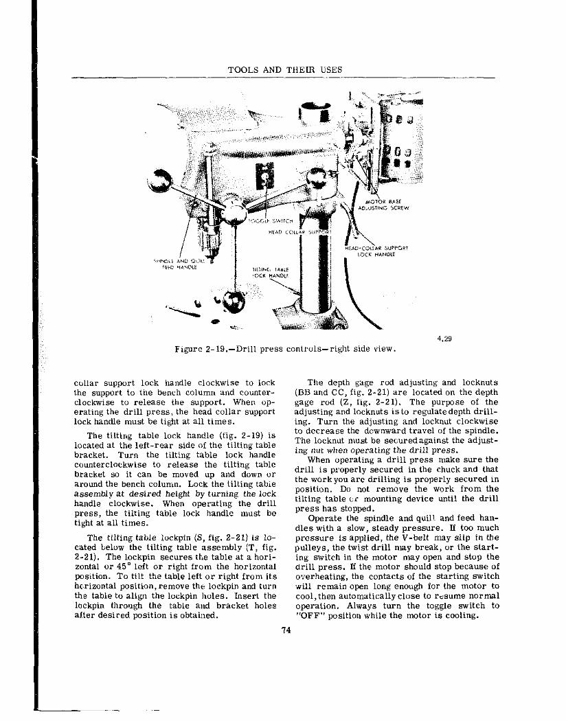
TOOLS AND THEIR USES
Figure Z-lg.-Drill press controls--right side view.
collar support lock handle clockwise to lock the support to the bench column and counter- clockwise to release the support. When op- erating the drill press, the head collar support lock handle must be tight at all times.
The tilting table lock handle (fig. Z-19) is located at the left-rear side of the tilting table bracket. Turn the tilting table lock handle counterclockwise to release the tilting table bracket so it can be moved up and down or around the bench column. Lock the tilting tabie assembly at desired height by turning the lock handle clockwise. When operating the drill press, the tilting table lock handle must be tight at all times.
The tilting table iockpin (S, fig. Z-21) is lo- cated below the tilting table assembly (T, fig. Z-21). The lockpin secures the table at a hori- zontal or 45” left or right from the horizontal position. To ti!t the table left or right from its horizontal position, remove the lockpin and turn the table to align the lockpin holes. Insert the lockpin through the table and bracket holes alIter desired position is obtained.
The depth gage rod adjusting and locknuts (BB and CC, fig. Z-21) are located on the depth gage rod (2, fig. Z-21). The purpose of the adjusting and locknuts is to regulatedepth drill- ing. Turn the adjusting and locknut clockwise to decrease the downward travel of the spindle. The locknut must be securedagainst the adjust- ing nut when operating the drill press.
When operating a drill press make sure the drill is properly secured in the chuck and that the workyou are drilling is properly secured in position. Do not remove the work from the tilting table tic mounting device until the drill press has stopped.
Operate the spindle and quill and feed han- dles with a slow, steady pressure. If too much pressure is applied, the V-belt may slip in the pulleys, the twist drill may break, or the start- ing switch in the motor may open and stop the drill press. If the: motor should stop because of o,verheating, the contacts of the starting switch wili remain open long enough for the motor to cool, then automatically close to r&ume normal operation. Always turn the toggle switch to “OFF” position while the motor is cooling.

Chanter 2-COMMON POWER TOOLS
44.60 Figure 2-20.-Drill press controls-left side view.
Check occasionally to make sure all locking handles are tight, and that the V-belt is not slipping and adjust as necessary in accordance with the manufacturer’s manual.
Before operating any drill press, visually inspect the drill press to determine if all parts are in the proper place, secure, and in good operating condition. Check all assemblies, such as the motor, head, puiieys, and bench for loose mountings.
While the drill press is operating, be alert for any sounds that may be signs of trouble, such as squeaks or unusual noise. Report any unusual or unsatisfactory performance to the petty officer in charge of the shop.
After operating a drill press, wipe off all dirt, oil, and metal particles. Inspect the V- belt to make sure no metal chips are imbedded in the driving surfaces.
BENCH GRINDER
The electric bench grinder (fig. Z-22) is designed for hand grinding operations, such as
sharpening chisels or screw drivers, grinding drills, removing excess metal from work, and smoothing metal surfaces. It is usually fitted with both a medium grain and fine grain abra- sive wheel; the medium wheel is satisfactory for rough grinding where a considerable quan- tity of metal has to be removed, or where a smooth finish is not important. For sharpen- ing tools or grinding to close limits of size, the fine wheel should be used as it removes metal slower, gives the work a smooth finish and does not generate enough heat to anneal the cut- ting edges.
When a deep cut is to be taken on work or a considerable quantity of metal removed, it is often practical to grind with the medium wheel first and finish up with the fine wheel. Most bench grinders are so made that wire brushes, polishing wheels, or buffing wheels can be sub- stituted for the removable grinding wheels.
To protect the opwator during the grinding operation, an eye shield and wheel guard are provided for each grinding wheel. A tool rest is provided in front of each wheel to rest and
75

TOOLS AND THEIR USES
AA
BB
cc
H
A
B
C
D
E
F
G
H
J
K
L
M
N
P
Q K
S
T
u
v
W
X
Y
z
DD
SPINDLE DRIVEN PULLLY
V-BELT
MOTOR DRIVE PULLEY
l/8 SQ x I SQ-END KEY
NO lo-24 x 5/a HDLS SET SCREW
MOTOR BRACKET STUD THUMBSCREW
MOTOR
MOTOR BASE 4ND BRACKET ASSEMBLY
l/4-20NC 2 x 1 SQ-NECK RD-HD CAR- RIAGE BOLT AND l/4-ZONC-2 SQ NUT DRILL CHUCK KEY
DRILL CHUCK KEY BRACKET
TOGGLE SWITCH PLATE
liEAD COLLAR SUPPORT
BENCH COLUMN
CORD
BENCH BASE
TILTING TABLE LOCKPIN
TILTING TABLE ASSEMBLY
DEPTH GAGE ROD BRACKET
HEX NUT
DRILL .CWUCK
CHUCK KNOCKOUT COLLAR
SPINDLE AND QUILL ASSEMBLY
DEPTH GAGE ROD
HEAC ASSEMBLY
DEPT4 GAGE ROD ADJUSTING NUT
DEPTH GAGE ROD LOCKNUT
SPINDLE DRIVEN PULLEY GUARD
4.29 Figure 2-21.-Drill press nomenclature.
guide the work during the grinding procedure. The rests are removable, if necessary, for grinding odd-shaped or large work.
When starting a grinder, turn it on ax! stand to one side until the ma&me comes up to full speed. There is always a passib:l~ity that a wheel may Ily to pieces wken. comir.;: up to full speed. Newr force work against a cr:!d wheel; apply work. gradually to pive the wheel,
an opportunity to warm. You thereby minimize the possibility of breakage.
Handle grinding wheels carefully. Before replacing a wheel always check it for cracks. Make sure that a fiber or rubber gasket is in place between each side of thewheel and its re- taining washer. Tighten the spi.ndle nut just enough to hold the wheel firmly:; if the nut is tightened too much the clamping strain, may
76

Chapter 2-COMMON POWER TOOLS
exceed the manufacturer’s recommended speed for the wheel.
iOR%iTL” MOUNTED 9NEI”.T”PL BENCH GRINDEi( **rri
4.31 Figure 2-22.-Bench grinder and wheei.
When grinding, always keep the work moving across the face of the wheel; grinding against the .same spot on the wheel will cause grooves to be worn into the face of the wheel. Keep all wheel guards tight and in place. Always keep the tool rest adjusted so that it just clears the wheel and is at cm just below the center line of the wheel, to prevent accidental jamming of work between tool rest and wheel.
Wear goggles, even if eye shields are at- tached to the grinder. Keep your thumbs and fingers out of the wheel.
damage the wheel. When selecting a replace- ment wheel, ascertain that the grinder will not

CHAPTER 3
In performing many jobs during your Navy career, you wili be required to take accurare measurements of materials and objects. It is common practice in the Nhvy to fabricate ma- terial for installation on a ship or in the field. For ea2mple, suppxc -;o- need a Pm:: of certain size to fit a space in 3 comps~t~ert. Yoli -would have to take measurements of the space and send them to a shop where the box would be built. This example suggests that the measure- ments you took and :hose taken in the process of building the box must be accurate. How- ever, the accuracy of the measurements will depend on the measuring tools used and one’s ability to “se them correctly.
Measuring tools are also used for inspecting a finished product or partly finished product. Inspection operations include testing or check- ing a piece of work by comparing dimensions of the workpiece to the required dimensions given on a drawing or sketch. Again, the meas- urements taken must be accurate and accuracy depends on one’s ability to “se measuring tools correct:y.
After studying this chapter, you should be able to select the appropriate measuring tool to “se in doing a job and be able to operate prop- erly a variety of measuring instruments.
RULES AND TAPES
There are many different types of measuring tools in use in the Navy. Where exact measure- ments are required, a micrometer caliper (mike) is used. Such a caliper: when properly used, gives measurements to within .OOl of an inch axuracy. On the other hand, where ac- curay is not extremely critical, the common rule oi tape will suffice for most measurements.
Figure 3-l shows some of the types of rules and tapes commonly used in the Navy. Of all measuring tools, the simplest and most common i,s the steel, rule. This rule is usu?.lly 6 or 12 i,nches in lengh, although other lengths are available. Steel ruies may be flexible or non.- flexible, brt the thinner thl? rule, the easier it
78
is to measure accurately because the division marks are closer to the work.
Generally a rule has four sets of gradua- tions, one on each edge of ea.& side. The !ongest lines represent the inch marks. On one ^_I~^ ---h ixch is divided into 6 equal spaces: ‘“gs, rat. so each space represents l/6 in. The other edge of this side is divided into sixteenths. The l/4-in. and l/2-in. marks are commoniy made longer than the smaller division marks to fa- cilitate counting, but the graduations are not, as a rule, numbered individually, as they are suf- ficiently far apart to be counted without diffi- culty. The opposite side is similarly divided into 32 and 64 spaces per inch, and it is com- mon practice to number every fourth division for easier reading.
There are many variations of the common rule, Sometimes the graduations are on one side on:y, sometimes a set of graduations is added across one end for measuring in narrow soaces, and sometimes onlythe first inch is di- vided into 64ths, with the remaining inches di- vided into 32nds and 16ths.
A metal or wood folding rule may be used for measuring purposes. These folding rules are usually 2 to 6 feet long. The folding rules cannot be relied on for extremely accurate measurements becalse a certain amount of play develops at the joints after they have been used for a while.
Figure 3-I.-Some common. types of rules.

Chapter S-MEASURING TOOLS ANPJD TECHNIQUES
Figwe 3-2.--Measuring with and reading a common rule.
29.124A Figure 3-S.-Measuring the length
of a bolt or screw-
44.67 Figure 3-4.-Measuring the outside
diameter of a pipe.
Steel tapes are made from 6 to about 300 ft. in length. The shorter lengths are frequently made with a curved cross section so that they are flexible enough to roll up, but remain rigid
79
44.68 Figure 3-5.-Measuring the inside
diameter of a pipe.
44.69 Figure 3-B.-Measuring the circum-
ference of a pipe with a tape.
when extended. Long,flat tapes require support over their full length when measuring, or the natural sag will cause an error in reading.
The flexible-rigid tapes are usually con- tained in metal cases into which they wind themselves when a button is pressed, or into which they can be easily pushed. A hook is pro- vided at one end to hook over the object being measured so one man can handle it without %+ sistance. On some models, the outside of the case ran be used a.5 one end of the tape when measuring inside dimensions.
MEASURING PROCEDURES
To take a measurement with a common rule, hold the rule with its edge on the surface of the object being measured. This will eliminate parallax and other errors which might result

TOOLS AND THEIR USES
,
44.263 44.263 Figure 3-I.-Using a folding rule to Figure 3-I.-Using a folding rule to
44.70
Figure 3-9.-Measur- ing the thickness of stock through a hole.
measure an inside dimension.
I---
44.24.1A Figure 3-8.-Measuring an inside
dimension with a tape rule.
44.24.1B Figure 3- lO.-Measuring an outside
dimension using a tape rule.
d?re to the thickness of the rule. Readthe meas- urement at the graduation which coincides with bolts or screws with countersinktype heads are the distzuce to be measured, and state it as be- measured from the top of the head to the op- ing so many inches and fractions of an inch. posite end, while those with other type heads (Fig. 3-2.) Always reduce fractions to their are measured from the bottom of the head. lowest terms, for example, 6/S inch would be called 3/4 inch. A hook or eye at the end of a Outside Pipe Diameters tape or rule is normally part of the first meas- ured inch. To measure the outside diameter of a pipe,
it is best to use some kind of rigid rule. A Bolts or Screws folding wooden rule or a steel rule is satis-
factory for this purpose. As shown in figure The length of bolts or screws is best meas- 3-4, line up the end of the rule with one side of
ured by holding iheim up against a rigid rule or the pipe, using your thumb as a stop. Then with tape. Hold both the bolt or screw to be meas- the one end he1.d in place with your thumb, swing wed and the ru!e up to your eye level so that the rule throul:h an arc and take the maximum your line of sight will not be in error in reading reading at the other side of the pipe. For most the measurement. As shown in figure 3-3, the practical purpases, the measurement obtained
80

Chapter 3-MEASURDJG TOOLS AND TECHNlQUES
: ‘, ‘\:, i.r j,,, ,..‘,/’ \r_, ,//-/’ >’ .,I’,--;. &S ’ 1 I 2 13
Figure 3-Il.-Simple calipers-noncalibrated. 4.17.4
by using this method is satisfactory. It is nec- through an arc and rearI the diameter across essary ihat you know how to take this measure- the maximum inside distance. This method ment as the outside diameter of pipe is some- is satisfactory for an approximate inside times the only dimension given on pipe measurement. specifications.
Pipe Circumferences Inside Pipe Diameters
To measure the circumference of a pipe, a To measure the inside diameter of a pipe flexible type rule th’at will conform to the cylin-
with a ruie, as shown in figure 3-5, hold the drical shape of the pipe must be used. A tape rule so that one corner of the rule just rests rule or a steel tape is adaptable for this job. on the inside of one side of the pipe. Then, with When measuring pipe, make sure the tape has one end thus held in place, swing the rule bean wrapped squarely around the axis of the
81

pipe (i.e., measurement should be taken in a plane perpendicular to the axis) to ensure that the reading will not be more than the actual circumference ot the pipe. This is extremely important when measuring large diameter pipe.
Hold the rule or tape as shown in figure 3-6. Take the reading, using the 2-inch gradu- ation, for example, as the reference point. In this case the correct reading is found by sub- tracting 2 inches from the actual reading. In this way the first 2 inches of the tape, serving as a handle, will enable you to hold the tape securely.
Inside Dimensions
To take an inside measurement, such as the inside of a box, a folding rule that incorporates a 6- or ‘l-inch sliding extension is one of the best measuring tools for this job. To take the inside measurement, first unfold the folding rule to the approximate dimension. Then PX- tend the end of the rule and read the length that it extends, adding the length of the extension to the length on the main body of the rule. (Fig. 3-7.) In this illustration the length of the main body of the rule is 13 inches and the extension is pulled out 3 3/16 inches. In this case the total inside dimension being measured is i6 3/X inche- a.
In figure 3-6 notice in the circled insert that the hook at the end of the particular rule shown is attached to the rule so that it is free to move slightly. When an outside dimension is taken by hooking the end of the rule over an edge, the hook will locate the endof the rule even with the surface from which the measurement is being taken. By being free to move, the hook will re- tract away from the end of the rule when an in- side dimension is taken. To measure an inside dimension using a tape rule, extend the rule be- tween the surfaces as shown, take a reading at the point on the scale where the rule enters the case, and add 2 inches. The 2 inches are the width of the case. The total is the inside di- mension being taken.
To measure the thickness of stock through a hole with a hook rule, insert the rule through the hole, hold the hook against one face of the stock, and read the thickness at the other face. (Fig. 3-9.)
Outside Dinxnsions
To measure an outside dimension using a tape rule, hook the rule over the edge of the
stock. Pull the tape out until it projects far enough from the case to permit measuring the required distance. The hook at the end of the rule is designed so that it will locate the end of the rule at the surface from which the meas- urement is being taken. (Fig. 3- 19.) When tak- ing a measurement of length, the tape is held parallel to the lengthwise edge. For measuring widths, the tape should be at right angles to the lengthwise edge. Read the dimension of the rule exactly at the edge of the piece being measured.
It may not always be possible to hook the end of the tape over the edge of stock being measured. In this case it may be necessary to butt the end of the tape against another surface or to hold the rule at a starting point from which a measurement is to be taken.
Distance Measurements
Steel or fiberglass tapes are generally used for making long measurements. Secure the hdok end of the tape. Hold the tape reel in the hand and allow it to unwind while walking in the direction in which the measurement is to be taken. Stretch the tape with sufficient tension to overwme sagging. At the same time make sure the tape is parallel to an edge qr the sur- face being measured. Read the graduation on the tape by noting which line on the tape coin- cides with the measurement being taken.
CARE
Rules and tapes should be handled carefully and kept lightly oiled to prevent rust. Never allow the edges of measuring devices to be- come nicked by strikingthem with hard objects. They should preferably be kept in a wooden box when not in “se.
To avoid kinking tapes,pull them straight out from their cases-do not bend them backward. With the windup type, always turn the crank clockwise-turning it backward will kink or break the tape. With the spring-wind type, guide the tape by hand. If it is allowed to snap back, it may be kinked, twisted, or otherwise dam- aged. Do not use the hook as a stop. Slow down as you reach the end.
SIMPLE CALIPERS
Simple calipers are used in conjunction with a scale to measure diameters. The calipers most commonly used in the Navy are shown in figure 3-11.
TOOLS AND TBEIR USES
82

Chapter 3-MEASURING TOOLS AND TECHNIQUES -
Figure 3-12.-Using an outside caliper.
A B
4.17C Figure 3-13.-Measuring the thickness
of the bottom of a cup.
Outside calipers for measuring outside di- ameters are bow-legged; those used for inside diameters have straight legs with the feet turned outward. Calipers are adjusted by pulling or pushing the legs to open or close them. Fine adjustment is made by tapping one leg lightly on a hard surface to close them, or by turning them upside down and tapping on the joint end to open them.
Spring- joint calipers have the legs joined by a strong spring hinge and linked together by a screw and adjusting nut. For measuring cham- fered cavities (grooves), or for use over flanges, transfer calipers are available. They are equipped with a small auxiliary leaf at- tached to one of the legs by a screw. (Fig. 3-11.) The measurement is made as with ordi- nary calipers; then the leaf is locked to the leg.
83
Figure 3-14.-Measuring a hard to reach inside dimension with an inside caliper.
Figure 3-i5.-Me:.suring the distance between two surfaces with an inside caliper.
The !egs may then be opened or closed as needed to clear the obstruciion, then brought bzrk and locked to the leaf again,thus restoring them to the original setting.
A different type of caliper is the hermaphro- dite, sometimes called odd-leg caliper. This caliper has one straight leg ending in a sharp point, sometimes removable, and one bow leg. The hermaphrodite caliper is used chiefly for locating the center of a shaft, or for locating a shoulder.
USING CALIPERS
A caliper is usually used in one of two ways. Either the caliper is set to ihe dimension of the work and the dimension transferred to a scale, or the caliper is set on a scale and the work machined until it checks with the dimen- sion set up on the caliper. To adjust a caliper to a scale dimension, one leg of the caliper should be held firmly against one end of the scale and the other leg adjusted to the desired dimension. To adjwt a caliper to the work, open the legs wider than the work and then bring them down to the work.
CAUTION: Never place a caliper on work that is revolving in a machine.

TOOLS AND THEIR USES
44.97A Figure 3-18.-Decreasing and increasing
the setting of a firm joint caliper.
Figure 3-16.-Measuring an inside diameter with an inside Caliper.
44.9lB Figure 3-lg.-Setting a com-
bination firm joint caliper for inside measurements.
Figure 3-17.-Setting a combination firm joint caliper. 44.97
Measuring The Diameter of Round or The Thickness of Flat Stock
To measure the diameter of round stock, or the thickness of flat stock, adjust the out- side caliper so that you feel a slight drag as you pass it over the stock. (See fig. 3-12.) After the proper “feel” has been attained, m~easure the setting of the caliper with a rule. In reading the measurement, sight over the leg of the caliper after making sure the caliper is set squarely with the face of the rule.
Then loosen the binding nut and open the caliper enough to remove it from the cup. Close the caliper again and tighten the binding nut to Seat in the slot at the end of the auxiliary arm. The caliper is now at the original setting, repre- senting the thickness.of the bottom of the cup. The caliper setting can now be measured with a rule.
To measure a hard to reach inside dimen- sion, such as the internal groove shown in fig- ure 3- 14, a lock- joint inside caliper should be used. The procedure followed for measuring a hard to reach outside dimension is used.
Measuring Hard to Reach Dimensions
Measuring The Distance Between Two Surfs.ces
To measure an almost inaccessible outside dimension, such as the thickness of the bottom of a cup, use an outside transfer firm-joint caliper an shown in figure 3- 13. When the proper “feel” is obtained, tighten the lock joint.
To .xasure the distance between hvo snr- faces withan inside caliper, first set thecaliper to the approximate distance being measured. HoLd the caliper with oneleg in contact with one of the surfaces being me;asured. (See fig. 3-15.) Then as you i,ncrease the setting of the caliper, move the other leg from left to right. Feel for
84
P

Chaoter 3-MEASURING TOOLS AND TECHNIQUES
4.17G
Figure 3-20.-Setting an outside spring caliper.
4.17H
Figure 3-21.-Setting an inside spring caliper.
the slight drag indicating the proper setting of the caliper. Then remove the caliper and measure the setting with a rule.
Measuring Hole Diameters
To measure the d&meter of a hole with an inside caliper, hold the caliper with one leg in contact with one side of the hole (fig. 3- 16) and, as you increase the setting, move the other leg from left to right, and in and out of the hole. When you have found the point of largest diam- eter, remove the caliper and m~;asure the cali- per setiing with a rule.
Setting A Combination Firm Joint Caliper
To set a combination firm joint caliper with a rule, when the legs are in position for oiitside nxasurements, grasp the caliper with both hands, as shown in figure 3-,l?A, and adjust
Figure 3-22.-Transferring a meas- urement from an outside to an inside caliper.
28.4A
Figure 3-23.-Caliper square (slide caliper).
both legs to the approximate setting. By adjust- ing both legs, the shape of the tool will be ap- proximately symmetrical. Thus it will maintain its balance and be easier to handle.
Chezk this approximate setting as shown in figure 3-17B. Sight squarely a.cross the leg at the graduations on the rule to get the exact set- ting required.
If it is necessary to decrease or increase the setting, tap one leg of the caliper, as shown in figure 3- 18. The arrow indicates the change in setting that will take place.
When the caliper is set for ir;side measure- ments, the same directions for adjusting the setting apply. Figure 3-19 shows how the end of the rule and one leg of the caliper are rested on the bench top so that they are exactly e”e~I with each other when the reading is taken.
Setting Outside And Inside Spring Calipers
To set a particular reading $0~ an outside spring caliper, first spen the caliper to the ap- proximate setting. Then, as sh’wn in figure 3-20, place one leg over the end of the rule, :stea’dying ii. with index finger. Make the final setting by si@ti,ng over the other leg of the
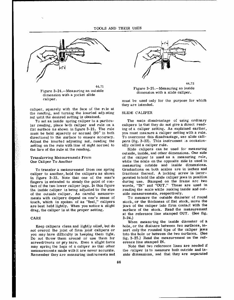
TOOLS AND THEIR USES
44.71 Figure 3-24.-Measuring an outside
dimension with a pxket slide caliper.
caliper, squarely with the face of the rr~le at the reading, and turning the knurled adjusting nut until the desired setting is obtained.
To set an inside spring caliper to a particu- lar reading, place both caliper and rule on a flat s*urface as shown in figure 3-21. The rule must be held squarely or normal (90” in both directions) to the surface to ensure accuracy. Adjust the knurled adjxsting nut, reading the setting on the rule with line of sight normal to the face of the rule at the reading.
Transferring Measurements From One Caliper To Another
To transfer a measurement from one spring caliper to another, hold the calipers as shown in figure 3-22. Note that one of the man’s fingers is extended to steady the point of con- tact of the two 1,ower caliper legs. In this figure the inside caliper is being adjusted to the size of the outside caliper. As careful measure- ments with calipers depend on one’s sense of touch, which is spokea of as “feel,” calipers are best held lightly. When you notice a slight drag, the caliper is at the proper setting.
CARE
Keep calipers clean and lightly oiled, but do not overoii the joint of firm joint calipers or you may have difficulty in keeping them tight. Do not throw them around or use them for screwdrivers or pry bars. Even a slight force may spring the legs of a caliper so that other measurements made withit are never accurate. Remember they are measuring instrum.ents and
44.72 Figure 3-25.-Measuring an inside
dimension with a slide caliper.
must be used only for the purpose for which they are intended.
SLIDE CALIPER
The main disadvantage of using ordinary calipers is that they do not give a direct read- ing of a caliper setting. As explained earlier, you must measui-e a caliper setting with a rule. To overcome this disadvantage, use slide cali- pers (fig. 3-23). This instrument ;.s occasion- ally called a caliper rule.
Slide calipers can be used for measuring outside, inside, and other dimensions. One side of the caliper is used as a measuring rule, while the scale on the opposite side is used in measuring outside and inside dimensions. Graduations on both scaies are in inches and fractions thereof. A locking screw is incor- porated to hold the slide caliper jaws in position during use. Stamped on the frame arc two words, “IN” and “OUT:’ These are used in reading the scale while making inside and out- side measurements, respectively.
To measure the outside diameter of round stock, or the thickness of flat stock, move the jaws of the caliper into firm contact with the surface of the stock. Read the measurement at the reference line stamped OUT. (See fig. 3-24.)
When measuring the inside diameter of a hole, or the dist3.nce between two surfaces, in- sert only the rounded tips of the caliper jaws into the hole or between the two surfaces. (See fig. 3-25.) Read the measurement on the ref- erence line stamped IN.
Note that two reference lines are needed if the v:aliper is to measure both outside and in- side dimensions, :and that they are separated
86

Chapter 3--MEASURING TOOLS A,ND TECHNIQUES
VERNIER SCALE
28.4B
Figure 3-26.-Veruizr caliper.
Figure 3-21.-Vernier scale principle.
by aa amount equal to the outside dimension of the rounded tips when the caliper is closed.
Pocket models of slide calipers are cam- manly made in 3-in. and S-in. sizes and are graduated to read in 32nds and 64ths. Pocket slide calipers are valuable when extreme pre- cision is not required. They are frequently used for duplicating work when the expense of fixed gages is not warranted.
both internal and external surfaces. Pock models usually measure from zero to 3 in., b sizes are available all, the way to 4 ft. In usi., the vernier caliper, you must be able to mea, we with a slide caliper and be able to read vernier scale.
PRINCIPLES OF THE VERNIER SCALE
VERNIER CALIPER
A vernier caliper (fig. 3-26) consists of an L-shaped member with a scale engraved on the long shank. A sliding member is free to move on the bar and -arries a jaw which matches the arm of the L. ‘. he vernier sale is engraved on a. small plate that is attached to the sliding member.
Perhaps the most distinct advantage (of the vernier caliper, over other types of calipei, is the ability to provide very ar:cux& measwe- ments over a large range. j:t can be used for
It would be possible to etch graduatio: l/1000 inch (0.001) in. apart on a steel rule sliding caliper as shown in figure 3-21. Th enlarged illustration shows two graduate scales. The top scale has division-j which a 0.025 inches apart. The small siiding low scale has 25 0.001 inch graduations which cz divide any of the main scale divisions of 0.0 inch into 25 parts. When the first graduati mirrlred “0” on this small sc:rle aligns with grac:iration on the main scale, the last, or 25 will also aiign with a graduation on the ma s.csle asi shown. Consequently, the small 0.
29.266A
67

TOOLS AND THEIR USES
29.%6(44B)A Figure 3-28.-Expanded view of the vernier scale.
29.266(44B)B Figure 3-29.-English-measure
vernier scale.
graduations are not a?snificant in this position. But when the z@ro graduation does not aiign with a graduation on the main scale, it can be readily determined how many thousandths the zero missed the0.025 inch graduation by count- iEg the misaligned graduation at either end of the small scale. When the zero or index line on the sliding scale does not quite reach the graduation, the amount of misaligr.ment must be subtracted, but when it passes the 0.025 gradu- ation from which the reading is made, it must be added. This illustrates the simple arrange- ment to increase the accuracy of a commw scale. Unfortunately,the 0.001 inch gradaations are not too legible and so the system is not practical. A vernier arrangement overcomes this problem.
VERNIER SCALE ARRANGEMENT
The main difference between the vernier SC& and the arrangement shown in fig. 3-27 is the spacing of the 25 divisions. Instead of 25 graduations crowds: within the space of one
main scale division, the vernier graduations are arranged at intervals exactly 0.001 inch less than the main scale graduations, as shown in fig. 3-28. This arrangement res-ults in an accumulation of misalignments starting with the first vernier grad?.-tion past the zero so that each may be marked as shown with a num- ber representing the space in t!!ousandths to the next npper scale graduation. For example, if the zero index line would be moved past the 8 inch graduation until the vernier graduation number 5 aligned with the next main scale graduation, the exact reading would be 8 inches plus 0.005 or 8.005 inches.
READING A VERNIER CALIPER
Figure 3-29 shows a bar 1 inch long divided by graduations into 40 parts so that each gradu- ation indicates one-fortieth of an inch (0.025 inch). Every fourth graduation is numbered; each number indicates tenths of an inch (4 x 0.025 inch). The vernier, which slides along the bar,is graduated into 25 divisions which to- gether, are as long as 24 divisions on the bar. Each division of the vernier is 0.001 inch smaller than each division on the bar. Verniers that are calibrated as just explained are known as English-measure verniers. The metric- measure vernier is read the @an@, except that the units of measurement are in millimeters.
In figure 3-30, insert A illustrates the Eng- lish measure vernier caliper. Insert B shows an enlarged view of the vernier section. AS you can see iE this figure, when the zero on the vernier coincides with the l-inch mark, no other lines coincide until the 25th mark on the vernier.
88

Chqter 3--MEASURING TOOLS AND TECHNIQUES
/ I /
1 i I
!
I ! ! I I
1 I
/
I L
29.266B
Figure 3-30.-Vernier caliper.
89