
A Programmable Heater Control Circuit for Spacecraft Technical Memorandum 108459 A Programmable...
58
NASA Technical Memorandum 108459 A Programmable Heater Control Circuit for Spacecraft (Center Director's Discretionary Fund Final Report Project No. 90-19) D.D. Nguyen, J.W. Owen, D.A. Smith, W.J. Lewter Structures and Dynamics Laboratory and Astrionics Laboratory Science Engineering Directorate National Aeronautics and Space Administration George C. Marshall Space Flight Center • MSFC, Alabama 35812 June 1994 https://ntrs.nasa.gov/search.jsp?R=19950004744 2018-06-16T20:14:36+00:00Z
-
Upload
nguyenkiet -
Category
Documents
-
view
216 -
download
0
Transcript of A Programmable Heater Control Circuit for Spacecraft Technical Memorandum 108459 A Programmable...

NASA Technical Memorandum 108459
A Programmable Heater Control Circuitfor Spacecraft(Center Director's Discretionary Fund Final Report
Project No. 90-19)
D.D. Nguyen, J.W. Owen, D.A. Smith, W.J. Lewter
Structures and Dynamics Laboratory
and Astrionics Laboratory
Science Engineering Directorate
National Aeronautics and Space AdministrationGeorge C. Marshall Space Flight Center • MSFC, Alabama 35812
June 1994
https://ntrs.nasa.gov/search.jsp?R=19950004744 2018-06-16T20:14:36+00:00Z


TABLE OF CONTENTS
Page
INTRODUCTION ................................................................................................................................. l
APPROACH .......................................................................................................................................... 3
SPACECRAVI" APPLICATIONS ......................................................................................................... 4
BREADBOARD DEVELOPMENT ...................................................................................................... 5
SOFTWARE DEVELOPMENT AND VERIFICATION ..................................................................... 7
PROTOTYPE DEVELOPMENT AND TESTING ............................................................................... 8
QUALIFICATION REQUIREMENTS ................................................................................................. 9
CONCLUSION ...................................................................................................................................... 10
REFERENCES ....................................................................................................................................... 11
iii


LIST OF ILLUSTRATIONS
Figure
1.
2.
3.
4.
5.
6.
7.
8.
Title Page
Typical thermostat ............................................................................................................ 1
Mechanical thermostat circuit .......................................................................................... 2
Analog control circuit ...................................................................................................... 2
Programmable heater control circuit with internal dc/dc converter ................................. 4
Programmable heater control circuit with battery power logic circuit ............................ 5
Programmable heater controller hybrid schematic .......................................................... 6
The dimension of prototype hybrid .................................................................................. 8
Prototype hybrid system test configuration ..................................................................... 9
PAGE IILQ414KNOT FILIV!.EDV


TERMS AND ABBREVIATIONS
Bootloader
Breadboard
CPU
D/A
EEPROM
EMI
mil-specification
MODB
MOSFET
PHCC
RAM
a program used for loading user programs into EEPROM
a printed circuit board that can be mounted and wired whatever circuitry is
designed
central processor unit
digital-to-analog
electrically erasable programmable read-only memory
electromagnetic interference
Military Standard Mil-M-38510J, Mil-STD-883C...
operation mode pin B on 68 HC11 microcontroller
metal oxide semiconductor field-effect transistor
programmable heater control circuit
random access memory
vii
PA_ __A_ _ FILME_


TECHNICAL MEMORANDUM
A PROGRAMMABLE HEATER CONTROL CIRCUIT FOR SPACECRAFT
Center Director's Discretionary Fund Final Report
Project No. 90-19
INTRODUCTION
Spacecraft thermal control is accomplished for many components through use of multilayer insu-
lation systems, electrical heaters, and radiator systems. The heaters are commanded to maintain compo-
nent temperatures within design specifications. Control of the heater system has been accomplished in
several ways including local thermostats, analog devices, and use of centralized digital control systems.
Many component heater control systems use thermostats to provide the desired temperature con-trol. Thermostats are mechanical devices which make or break electrical contact due to change in tem-
perature. This is usually accomplished via differential thermal expansion of a bimetallic disk thatchanges shape, and therefore position, with temperature. A typical thermostat is shown schematically in
figure 1. Since a thermostat can conceivably fail in the closed position, two thermostats are used in
spacecraft operation and are wired in series so that the circuit breaks if either of the thermostats open.Further, to provide the complete redundancy needed for spaceflight, two parallel circuits, each with two
thermostats, are required as a safeguard against one of the thermostats failing in the open position.
Figure 2 shows typical circuitry using thermostats.
Weld Cap
100314-1_
Header Body201434-1
Wave Washer_201702-1
Arm
100302-( )Pin
201689-( )
Terminal
// 100301-1
_-__'_ F Glass Seal
I kJ I I LJl / /-StationaryContaot
I I I I//L'_'_'_' / _ Movable Contact
tl_1 1[////////11 JV_#¢._ I _ Insulator
"1 -LJ / 201701-1I ._¢ _ I_,,--,,_ _ Disk Retainer
201699-1_cap
/ _ %-- Pin Guide 201857-( )
_4 _-- Disk 201700-1
201902-( )
Figure 1. Typical thermostat (courtesy of Elmwood Sensors, Inc.).

+
28 VDC
power bus
thermostat
0
Thermostatically Control Heater
I componentstrip heater
28 VDC VDC
power busA _ p°weBbUS
Multiple Circuits For Redundancy
Figure 2. Mechanical thermostat circuit.
Alternatives to mechanical thermostats have included analog circuits in varying design applica-
tions, using solid state devices. Analog devices have the advantage of precise temperature control, for
components with operational temperature requirements which must be maintained within small limits,
such as spacecraft pointing and control systems. A schematic of an analog controller is shown in figure3. The analog circuitry must also be designed with redundancy in spacecraft applications.
I M28 VDC dc/dc
power bus regulator
m
he, ,rI--Icontroller H conditioner
heatertemperature
sensor
Figure 3. Analog control circuit.
Some spacecraft have used central digital control systems to accomplish temperature control of
components. This involves design of a central digital computer which receives many analog inputs from
distributed component controllers. The analog signals are converted to digital data and the control func-
tions are determined by the central processor unit (CPU). The heaters are commanded individually fromthe CPU based upon control logic. For some applications, proportional control is provided through volt-
age regulation.
Several disadvantages with these systems can be identified. For thermostatically controlled sys-
tems the mechanical thermostat itself has a potential for failure, either opened or closed. The thermostat,
being mechanical, provides no temperature data; therefore, separate temperature sensors must be pro-
vided by a central spacecraft data system. The thermostats have a predetermined set point (temperature)and dead band (control range) that cannot be altered.
2

Analogdeviceseliminatethe mechanical problems associated with thermostats, but they also
have a predetermined set point and dead band that cannot be altered once physically integrated into the
spacecraft. The analog device has no feedback of temperature data for monitoring the thermal condition
of the component, even though one or more temperature sensors are integrated into the circuit. If the
component temperature must be monitored, another sensor must be installed and integrated with the
spacecraft central data system.
The central digital control systems provide the most versatility and flexibility with respect tocontrol authority, data acquisition, reprogramming, and sometimes proportional control. These systems
are usually expensive, require substantial integration during spacecraft assembly, and result in signifi-
cant spacecraft wiring for the control instrumentation.
With the advanced technology in both electronic sensing and computer programming, this devel-
opment introduces solid state design, use of control instrumentation as data available to the central datasystem, reprogramming capability of the local microprocessor during the spacecraft mission, if required,
and the elimination of significant spacecraft wiring. The hybrid integrated circuit has a temperature sens-
ing and conditioning circuit, a microprocessor, and a heater power and control circuit. This program-mable heater control circuit (PHCC) is miniature and housed in a volume which allows physical integra-
tion with the component to be controlled. Applications might include alternate battery-powered logic-
circuit configurations. A prototype unit with appropriate physical and functional interfaces was procured
for testing. The physical functionality and feasibility of the hybrid integrated circuit were successfullyverified.
APPROACH
The effort was to develop a small, integrated hybrid circuit that captured the advantages of both
central digital controllers and local autonomous control systems. A simplified schematic of the device is
shown in figure 4. Optional configurations are shown in figure 5. The advantages of this design includesolid state design, use of control instrumentation as data available to the central data system (through a
time-multiplexed data bus), reprogramming capability of the local microprocessor during the spacecraftmission, if required, and the elimination of significant spacecraft wiring (the device only requires a
power bus interface and a data bus interface).
The hybrid integrated circuit has a temperature sensing and conditioning circuit, a microproces-sor, and a heater power and control circuit. The device is miniature and housed in a volume which
allows physical integration with the component to be controlled. In typical operation, the set point tem-
perature and dead band control range are programmed in the heater control logic ofthe microprocessor.
Temperature sensors reference the component temperature through signal conditioners and an analog-to-
digital converter. Based on the reference temperature, the microprocessor issues commands to the heatercontrollers to turn on or off (voltage regulation, or proportional control is not provided in this design,
with the exception of varying the heater duty cycle over time). The integrated circuit, through the micro-
processor, also interfaces with the central data bus. Upon interrogation by the spacecraft CPU via thisbidirectional communication link, component temperature data is passed upon demand to the spacecraft
central processor. Additionally, the status of the heaters (on or off), the duty cycle of the heaters, and
computed functions such as power utilization can be communicated and eventually telemetered to
ground stations. The central spacecraft computer system also has the capability of reprogramming or
reconfiguring the local microprocessor heater control logic to adjust to unexpected or anomalous events.
3

m
i
i;I
SERIAL_ _ MICROCONTROLLER COMMUNICATIONS
| POWER
"_ 12 BIT D/A .____NSTRUMENT. --'--ISWITCH ]
.| CONVERTER - I AMPLIFIER _--
[ II_ 8/1 ANALOG _,I MULTIPLEXER [
5V DC-DC 15V 11 S V CONVERTER I TEMPERATURE
28 VOLT SPACECRAFT POWER BUS
i SPACECRAFTy CENTRAL
PROCESSOR
--I HEATER
TEMPERATURE
SENSOR
( 6 POSSIBLE)i
Figure 4. Programmable heater control circuit with internal dc/dc converter.
Additionally, the local microprocessor can be programmed to react to events such as temperature sensorfailures, heater circuit failures, etc., and take action to use redundant systems. The versatility and utility
of the device is quite good and offers substantial design and operational advantages to spacecraft thermal
designers.
SPACECRAFT APPLICATIONS
Potential applications of the PHCC are believed to exist both in the spacecraft and payload areas.
The primary application is believed to be free-flying spacecraft with somewhat tight componenttemperature-control requirements. These include applications such as nickel-hydrogen battery tempera-
ture control, pointing and control system temperature control, low temperature conditioning of science
instruments, telescope mirror assembly temperature control, and heater control for variable conductance
heat pipe systems. The payload applications might include alternate design configurations, such as
battery-powered logic circuits, for short duration missions, eliminating the need for internal dc/dcconversion within the PHCC (see fig. 5). Control requirements would be similar to the spacecraft
applications discussed above. Payload applications may not require an interface with a central data
system but might require expanded memory in the microprocessor, with data retrieval occurring after
flight. These design options can be made available through several off-the-shelf controllers, with varying
design features selected by the spacecraft or payload designer. Depending upon the spacecraft marketand unit cost for these devices, these solid state programmable systems could replace mechanical
thermostats, analog devices, and central controllers on future spacecraft programs.
4

ISPACECRAFT J_'_ CENTRAL J
PROCESSOR I
FI HEATER I
TEMPERATUREISENSOR I
(6 POSSIBLE)_,
28 VOLT SPACECRAFT POWERBUS
Figure 5. Programmable heater control circuit with battery powered logic circuit.
BREADBOARD DEVELOPMENT
A fully functional breadboard of the PHCC was developed. The attached schematic, figure 6,shows the circuitry developed to accomplish this task. The Motorola M68HC811 E2 microcontroller was
chosen to be the heart of the design. This controller is in Motorola's HC11 family of microcontrollers. It
features 2 kilobytes of electrically erasable programmable read-only memory (EEPROM), an 8-bit
analog-to-digital converter with eight multiplexed inputs, an RS232 port, internal timers, an 8-bit bidi-
rectional port, and an 8-bit output port. The Maxim MAX700 was chosen to provide the reset signal
upon power-up. The microcontroller can read eight analog sensor input signals. These are input through
an 8-to-1 analog multiplexer. The multiplexer used is the Analog Device 7503. The input are selected bythree control lines from the microcontroller. Two of these inputs are AD590 temperature transducers that
are mounted internal to the case. The other six inputs are set up to be AD590 inputs but can also be used
to input other signals. Each external input has a pair of external pins with a 15-V reference signal on one
pin and the other going to an input of an 8-to-1 multiplexer and to a 10-k ohm resistor to ground. The
output of the multiplexer then goes to the plus input of the instrumentation amplifier. The minus input of
the instrumentatl'0n amplifier is connected to the output of a 12-bit digital-to-analog (D/A) converter.
The D/A used is the MicroNetworks MN371. The 12 input bits to the D/A come from the microcon-
troller digital output ports. The instrumentation amplifier used is the Burr Brown PGA200 program-
mable gain instrumentation amplifier. It has four selectable gain of 1, 10, 100, 1,000. The purpose of the
D/A converter and the selectable gain is to provide a dc offset and amplification of the signal for betterresolution and control around a setpoint.
5

ii It
I÷!
I
J
-o
II
- "._lUl_
l
i!
I
, t L1 t
i:l ,t,'!', ,'!
II I
,'i ,,5
,,-II-i-
.1....7,1444
"i '11
_>ili. !
ii
d
0
N
c_
d_,6
6

Communication with a main computer is accomplished through the microcontroller's RS232
port. The digital transmit and receive lines from the microcontroller are level-converted and bufferedwithin the hybrid. The transmit line is buffered by a 1488 line driver and the receive line is buffered by a1489 line receiver.
Initial programming of the 2k of EEPROM is done through the RS232 port. A "program mode"
is entered when the MODB line that comes to an external pin is tied to ground. A "Bootloader" program
is loaded into the random access memory (RAM) and takes control of the microcontroller to load the
EEPROM. Software or "control code" is developed using the HC11 assembly language and assembler. It
should be noted that the EEPROM can be reprogrammed under computer control through the RS232
port connected to the computer used for monitoring and control. Changing set points or control algo-
rithms can be accomplished easily through the monitor and control computer also.
Four heaters can be controlled from this hybrid. There are two external lines provided for each
heater. The load voltage brought in on the "28 V" external pin is connected to one of these lines. Theother line is connected to the drain of an International Rectifier IRFF130. This metal oxide semiconduc-
tor field-effect transistor (MOSFET) is rated at 100 V and has an "on" resistance of less than 0.2 ohms.The MOSFET's are controlled by outputs from the microcontroller that are optically isolated from the
MOSFET by an HP2200 optical insulator.
SOFTWARE DEVELOPMENT AND VERIFICATION
The PHCC software is shown in appendix A. The software was developed using the breadboardunit discussed above. The software is designed to set, monitor, and program the heater controller and is
as simple and flexible as possible. Some of the function features in the software include the following:
• Header files
• Turning cursor on and off
• Setting screen colors
• Screen locations
• User inputs
• Module functions
• Global variables
• Communicating with heater controller
• Controlling cursor
• Initializing stack, output ports, heaters
• Initial conditions
• Heater control
• Reading temperature.
Verification was also accomplished on the prototype unit when software was loaded and each function
was successfully executed.
7

PROTOTYPE DEVELOPMENT AND TESTING
To verify the physical functionality and feasibility of fabrication of the hybrid integrated circuit,
a prototype unit was procured and built from non Mil-certified parts. The prototype unit did not include
the internal dc/dc converter required for the flight version. This function was simulated external to the
prototype. The unit was delivered and burn-in tests were accomplished, and the software was loaded andverified. Of four units delivered and tested, one unit failed the burn-in test. The dimensions of the proto-
type are shown in figure 7. The width is 2 inch and length is 2.85 inch. The external pin connections areon 0.15-inch spacing and extend 0.25 inch frorh the body on each side. The mounting flanges extend
0.35 inch from each end and give an overall length of 3.85 inch. The base of the package is 0.0625 inchthick, and the diameter of the mounting holes is 0.16 inch with the centers 3.175 inch apart. The overall
height is 0.5675 inch.
PROTOTYPE HYBRID PRODUCED BY
ARGO TRANSDATA CORPORATION
Figure 7. The dimension of prototype hybrid.
The prototype Hybrid weighs approximately 160 g (5.6 oz). The quiescent power consumed with
all heaters "off" and including the dc/dc converter is 1.5 W. The complete system test configuration is
shown in figure 8. The test procedures and results are described and tabulated as shown in appendix B.

28 volt.
Power Supply
P rot or ype
llybrldDC/DC
Converter "
RS232 Null Modem
Connection
IP_M Compat _b[e
P C
Figure 8. Prototype hybrid system test configuration.
QUALIFICATION REQUIREMENTS
Based upon the above discussion, the PHCC has been shown to be a feasible design concept. Thesoftware is fully developed and verified. Further development is required in the area of procurement and
testing of a Mil-certified part with an internal dc/dc converter for generic qualification testing. The test-
ing should include thermal vacuum performance testing, thermal cycling, vibration, and electromagnetic
interference (EMI) testing. Appropriate test plans should be generated to qualify the device for a wide
range of spacecraft applications as an off-the-shelf item. Military Standard 1540B provides qualification
test requirements routinely accomplished at MSFC. Should a joint venture be initiated with a potentialPHCC vendor, MSFC qualification testing is an option that is available.
9

CONCLUSION
The PHCC design has progressed to the definition of a very efficient and compact device includ-
ing an internal dc/dc converter. The software is fully developed and verified. A breadboard unit has been
developed and tested with applicable software. Also a prototype unit with appropriate physical and
functional interfaces was procured for software testing and for burn-in testing. The remaining work to
develop a flight-qualified device includes fabrication and testing of a Mil-certified part, with an internaldc/dc converter.
An option for completing the PHCC flight qualification testing is to enter into a joint venture
with industry. The government contribution would include the design, software, and development his-
tory; also, the government could provide the qualification testing and data analysis. The industry partici-
pation would include fabrication of the units for testing, per Mil-specification. Successful completion of
the test program would result in a commercially marketable device or family of devices, with applica-
tions to spacecraft thermal control systems.
10

REFERENCES
1. "Thermal protection system of the space shuttle." NASA-CR-4227, 1989.
2. Humphries, R., and Wegrich, R.: "A Survey of Spacecraft Thermal Design Solutions." ESA and
ASI, European Symposium on Space Environmemtal Control Systems, 4th, Florence, Italy, 1991.
3. Best, R.: "Thermal Control Subsystem of the Space Telescope Faint Object Camera." SS-DS-2060,
Dornier System, 1984.
4. Owen, J.R., Editor: "Thermal Analysis Workbook." NASA, Marshall Space Flight Center,
Huntsville, Alabama, 1991.
5. Hordeski, F.M.: "Control System Interfaces." Prentice Hall Inc., New Jersey, 1992.
6. Gates, S.C., Editor: "Laboratory Automation Using the IBM PC." Prentice Hall, New Jersey, 1989.
7. Zuech, N., Editor: "Handbook of Intelligent Sensors for Industrial Automation." Addison-Wesley
Publishing Co. Inc., Massachusetts, 1991.
8. Tzafestas, S.G., Editor: "Engineering System with Intelligence." Kluwer Academic Publisher, The
Netherlands, 1991.
9. Ollero, A., Editor: "Intelligent Components and Instruments for Control Application." PergamonPress, Great Britian, 1993.
10. Anderson, C.W., and Kosut R.L.: "Adaptive Robust Control, On-Line Learning." Proc. IEEE
Conference on Decision and Control, Brighton, England, 1991.
11. Ollero, A., Garcia-Cerezo A., and Aracil J.: "Design of Rule-Based Expert Controllers." ECC91
European Control Conference, Grenoble, France, 1991.
12. Paul, C.J., Acharya, A., Black, B., and Strosnider J.K.: "Reducing Problem-Solving Variance to
Improve Predictability." Communications of the ACM, 1991.
13. Shinners, S.M.: "Modern Control System Theory and Design." J. Wiley, New York, 1992.
11


APPENDIX A
PHCC SOFTWARE
PA_I[ lANK NOT FILMED
13


PHCC Software
/*
*!
include statements for header files
#include <stdio.n>
_include <s_dlib.h>
#include <conio.h>
#include <mash.n>
#include <dos.h>
#include <_lme.n>
#include <sys\types.h>
#include <sys\timeb.h>
#include <bios.h>
#include "rs232.h"
/*
*I
definitions used in turning cursor on and off........................ o. • ............................ o ..... o ......... ° ........ ° ............ o oo °° °o o° °o ..... ° o. °o °° °° ° ........... °° oo
aeeeeeeeeeeeeeeeeeeeeeeeeeeeeeeeeeeeeeeeeeeeeeeeeeeeeeeeeeeeeeeeeeee
#define VIDEO IO 0xl0
#define SET CRSR I
/*
,/
o definitions used for setting screen colors................................................................................................................. ° °. • ............ ° ....
aeeeeeeeeeeeeeeeeeeeeeeeeeeeeeeeeeeeeeeeeeeeeeeeeeeeeeeeeeeeeeeeeeee,
#define BLACK 0x00
#define HLUE 0xl0
#define GREEN Ox20
@deflne CY_4 0x30
#define RED 0x40
#define MAGENTA 0x50
#define ERO_ 3x60
{define WHITE 0x70
#define BLACK ON 0x00P_ PAG_ IIIL_NK NOT FII..ME_
15

#define ELUE ON 0x01
#define GREEN O_ 0x02
#define tYAN ON 0x03
,#define RED ON 0x04
#define MAGENTA O_ 0x05
#define BROWN ON 0x06
#define _ITE ON 0x07
#define GREY ON Ox08
#define BRIGHT BLUE ON 0x09
#define BRIGHT GREEN ON 0x0A
#define BRIGHT CYAN ON 0x0B
#define BRIGHT RED ON 0x0C
#define BRIGHT MAGENTA ON 0x0D
#define YELLOW ON OxOE
#define BRIGHT WHITE ON Ox0F
/*
,/
o definitions used for screen ioca_ions
16
#define PLATE UL ROW !
#define PLATE UL COLUMN 12
#define PLATE--ROWS 15
#define PLATE COLUMNS 55
#define HEATER1 UL ROW 2
#define HEATER1 UL COLUMN 14
#define HEATERI-ROWS 5
#define HEATER1 COLUMNS 19
#define HEATER2 UL ROW 7
#define HEATER2-UL-COLUMN _4
#define HEATER2-ROWS
#define HEATER2-COLUMNS ii
#define SENSOR1 UL ROW 4
#define SENSOR1 UL COLUMN !8
#define SENSOR1 ROWS 1
#define SENSOR1 COLUMNS 6
#define SENSOR2 UL ROW 4
#define SENSOR2 UL COLUMN 56
#define SENSOR2-ROWS i
#define SENSOR2 COLUMNS 6
#define SENSOR3 UL ROW 8
#define SENSOR3 UL COLUMN 56
#define SENSOR3 ROWS 1
#define SENSOR3 COLUMNS 6
#define SENSOR4 UL ROW 12
#define SENSOR4 UL COLUMN 18
#define SENSOR4-ROWS !
#define SENSOR4 COLUMNS

#define SENSOR5 UL ROW 12
#define SENSOR5 UL COLUMN 56
#define SENSOR5 ROWS 1
#define SENSOR5 COLUMNS 6
#define ROW_query_window 18
#define COLUMN_query_window 40
#define ROW HEATER1 SETPOINT 3
#define COLUMN HEATER1 SETPOINT !
#define ROW HEATER2 SETPOINT 9
#define COLUI_N HEATER2 SETPOINT 70q
#define ROW NUMBER TO AVERAGE 23
#define COLUMN NUMBER TO AVERAGE 30
#define ROW ERROR MESSAGE 16
#define COLUMN ERROR MESSAGE 20
/*
,/
o definitions used for getting information from user
#define RETURN 13
#define ESCAPE 27
#define BACKSPACE 8
#define LEFT ARROW 75
#define RIGHT ARROW 77
#define CURSOR 176
#define F1 59
#define F2 60
#define F3 61
#define F4 62
#define F5 63
#define F6 64
#define F7 65
#define F8 66
#define F9 67
/*
,/
i_aa_a_a_a_a_aaa_aaaaa_a_aaaaaaa_aaa_aa_aaaaaaaa_aaaaa_
o function declarations for functions in this moduleo .................. ,. ,° ,, .0 .......................... ,...... ° ..... ° .................. °. • ...... • ..... ° ...... ,° °. °° .° .........
aeeeeeeeeeeeeeeeeeeeeeeeeeeeeeeeeeeeeeeeeeeeeeeeeeeeeeeeeeeeee_
void send_byte to heater( unsigned char c ) ;
unsigned char receive_byte from heater( unsigned comm_port ) ;
void wait_for_comm_port_data( void ) ;
void turn_on_cursor( void ); 17
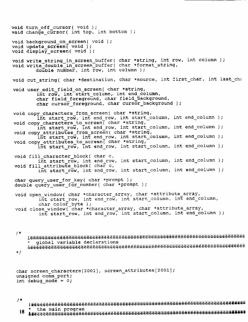
void turn off cursor( void ) ;
void change_cursor( int top, int bottom );
void background on screen( void ) ;
void update_screen( void );
void display_screen( void );
void write_string_in_screen buffer( char *string, int row, int column );void write double in screen-buffer( char *format_string,
double number, int _ow, int column ) ;
void cut.string( char *destination, char *source, int first_char, int last_ch_
void user edit field on screen( char *string,
int roW, int-start column,- int end column,
char field_foreground, char field_background,
char cursor_foreground, char cursor_background );
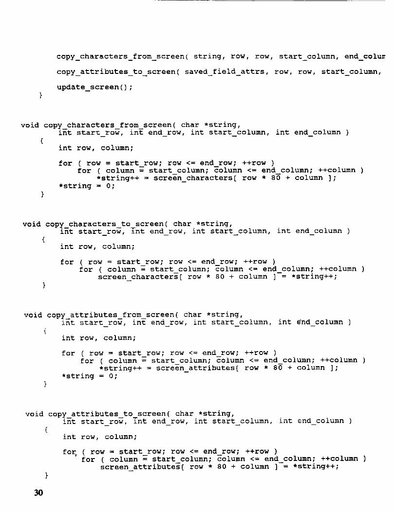
void copy_characters_from screen( char *string,
int start row, int end row, int start_column, int end column );
void copy_characters_to screen_ char *string,int start row, [nt end row, int start column, int end column ) ;
void copy_attribuEes_from screen( char *string,
int s_art row, inE end_row, int start_column, int end_column ) ;
void copy_attributes_to_screen( char *string,
int start_row, int end_row, int start_column, int end_column );
void fill character block( char c,
int start row, int end row, int start_column, int end_column ) ;
void fill attribute_block( char c,
int start_row, int end_row, int start_column, int end_column ) ;
char query_user_for_key( char *prompt ) ;
double query_user_for_number( char *prompt ) ;
void open_window( char *character_array, char *attribute array,int start row, int end row, int s_arn_column, int end_column,
char color_byte );void close window( char *character_array, char *attribute_array,
int start_row, int end_row, int start_column, int end_column ) ;
/*
./
char screen characters[2001], screen_attributes[2001];
unsigned comm_port;
int debug_mode = O;
the main program

*/
int main( int argc, char *argv[] )
{static char string[256];
char key = ' '-!
unsigned char heater status;
unsigned char sensor[ data;
unsigned char sensor2-data;
unsigned char sensor3-data;
unsigned char sensor4-data;
unsigned char sensorS--data;
double sensorl_temperature = 0.0;
double sensor2_temperature = 0.0;
double sensor3_temperature = 0.0;
double sensor4_temperature = 0.0;
double sensor5_temperature = 0.0;
double averages = 0.0;
double number_of_readings_to_average = i0.0;
unsigned char heater select;
unsigned char sensor-select;
unsigned char set_point;
FILE *fileptr;
/*
Check for debug mode.
*/
if ( argc > 1 )
if { (argv[l]) [0] == 'd'
debug_mode = !;
I I (argv[l])[0] == 'D' )
/*
Set up the screen.
*/
turn off cursor();
background_on_screen();
/*
Set up the comm port.
*/
do
{
key = query_user_for_key( "Enter 1 for COMI or 2 for COM2" );}
while( key != 'I' && key != '2' && key != ESCAPE );
if ( key == ESCAPE ) 19
{turn on cursor() ;return Y ;
}
if ( key == '2' ) comm_port = COM2;
else comm_port = COMI;
initialize_comm_port( comm_port,
_toMcat8 I _COM_STOPI i _COM__OP_ITY i _C0M9600 );
if ( check_status( comm_port ) & DATA_READY_BIT )
receive_byte( comm_port );
/*
Main program loop.
*/
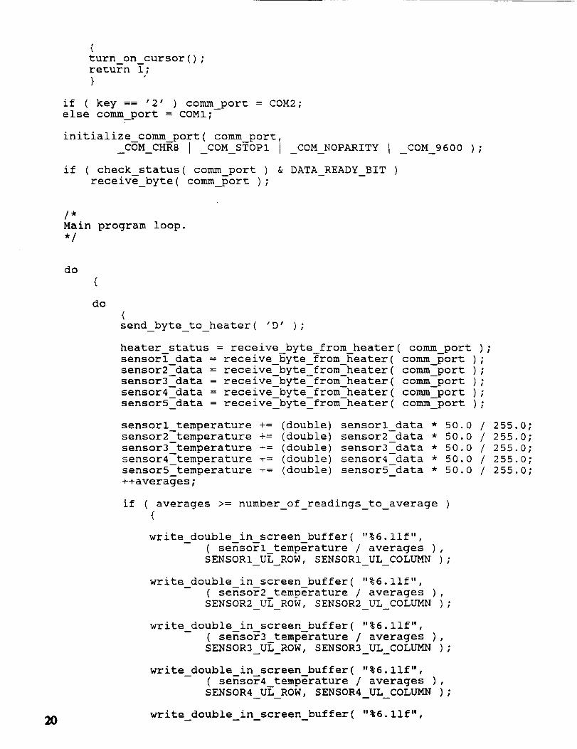
do
do
{send_byte_to_heater ( 'D' ) ;
heater status = receive_byte_from heater( comm_port ) ;
sensor[ data = receive_byte from heater( comm_port );
sensor2--data = receive_byte_from-heater( comm_port );
sensor3 data = receive_byte from heater( comm_port ) ;
sensor4_data = receive_byte_from_heater( comm_port ) ;
sensor5_data = receive_byte_from_heater( comm_port ) ;
sensorl_temperature += (double) sensorl_data * 50.0 / 255.0;
sensor2_temperature += (double) sensor2_data * 50.0 / 255.0;
sensor3 temperature += (double) sensor3_data * 50.0 / 255.0;
sensor4_temperature _= (double) sensor4_data * 50.0 / 255.0;
sensor5_temperature += (double) sensor5_data * 50.0 / 255.0;
++averages;
if ( averages >= number of readings_to_average )
{
write double in screen buffer( "%6.11f",
( sensorl_temperature / averages ),
SENSOR1 UL ROW, SENSOR1 UL COLUMN ) ;
write double in screen buffer( "%6.11f",
( sensor2 temperature / averages ),
SENSOR2 UL ROW, SENSOR2 UL COLUMN ) ;
write double in screen buffer( "%6.11f",
- ( sensor3_temperature / averages ),
SENSOR3 UL ROW, SENSOR3 UL COLUMN );
write double in screen buffer( "%6 llf"• t
( sensor4_temperature / averages ),SENSOR4 UL ROW, SENSOR4 UL COLUMN ) ;
write double in screen buffer( "%6.11f",

( sensor5 temperature / averages ),
SENSOR5_UL ROW, SENSOR5 UL COLUMN ) ;
sensorl_temperature = 0.0;
sensor2 temperature = 0.0;
sensor3_tempera_ure = 0.0;
sensor4_temperature = 0.0;
sensor5 temperature = 0.0;averages = 0.0;}
if ( heater
else
{
fill attribute_block( WHITE ON I RED,
HEATER1 UL ROW, HEATERI--UL ROW + HEATER1 ROWS - i,
HEATERI_UL_COLUMN, HEATERI_UL_COLUMN + HEATERICOLUMNS _ 1
fill attribute block( BRIGHT WHITE ON I RED,
SENSOR1 UL--ROW + i, SENSOR1 UL--ROW + 1 + SENSORI_ROWS _ i,} SENSORI_UL_COLUMN, SENSORI_UL_COLUMN + SENSORI_COLUMNS _ !
if ( heater status & 2 ){
fill attribute block( WHITE ON I BROWN,
HEATER2 UL-ROW, HEATER2-UL ROW + HEATER2 ROWS - i,
HEATER2_UL_COLUMN, HEATER2_ULCOLUMN + HEATER2_COLUMNS _ !
fill_attribute block( BRIGHT _HITE ON I BROWN,
SENSOR5 UL--ROW + i, SENSOR5 UL-ROW + 1 + SENSOR5 ROWS} SENSOR5_UL--COLUMN - i,
- , SENSOR5 UL_COLUMN + SENSOR5 COLUMNS - 1else
{
fill_attribute block( WHITE ON I RED,
HEATER2 UL ROW, HEATER2--UL ROW + HEATER2 ROWSHEATER2_UL--COLUMN, _ - 1
-- HEATER2_UL_COLUMN+ HEATER2_COLUMNS _ 1
fill attribute block( BRIGHT WHITE ON I RED,
SENSOR5 UL ROW + i, SENSOR5 UL-ROW + 1 + SENSOR5 ROWS - i,} SENSOR5_UL_COLUMN, SENSOR5UL__OLUMN + SENSOR5_COLUMNS _ i
fill attribute block( BLACK ON I WHITE,
SENSOR1 UL-ROW, SENSORI-UL ROW + SENSOR1 ROWSSENSORI_UL--COLUMN, - 1
-- SENSORI_UL_COLUMN + SENSORI_COLUMNS - 1 );
fill_attribute block( BLACK ON I WHITE,
SENSOR5 UL ROW, SENSORS--UL ROW + SENSOR5 ROWSSENSOR5_UL--COLUMN, - 1
-- SENSSR5_UL_COLUMN + SE--NSOR5_COLUMNS - i );
status & !{
fill_attribute block( WHITE ON I BROWN,
HEATER1 UL--ROW, HEATERI-UL ROW + HEATER1 ROWS TERC L COL -, HEATERI_UL_COLUMN + HEATERI_COLUMNS _ 1
fill attribute block( BRIGHT WHITE ON I BROWN,
SENSOR1 UL-ROW + i, SENSOR1 UL-ROW + 1 + SENSOR1 ROWS - i,
} SENSORI_UL_COLUMN, SENSORI_UL_COLUMN + SENSORI_COLUMNS _ 1
21

"% 01f % 01f "sprintf( string, . .
number of readings_to_average, averages + 1.0 );
write_string in screen buffer( string,ROW NUMBER TO AVERAGE, COLUMN NUMBER TO AVERAGE ) ;
update_screen();}
while(!kbhit() ) ;
/*
Get the key that was pressed.
*/
do
{key = (char) getch() ;
if ( key == 0 ) getch();
}while(kbhit() ) ;
/*
Set point command.
*/
22
if ( key == 's' II key == 'S' )
{
do
{heater_select = (unsigned char) query_user_for_number(
"Enter 1 or 2 to select the heater" ) ;
}while( heater_select < 1 I I heater_select > 2 );
do
(sensor select = (unsigned char) query user for number(
- "Enter i, 2, 3, 4, or 5 to select the sensor" ) ;
}while( sensor_select < 1 I I sensor_select > 5 ) ;
do
(set_point = (unsigned char) ( query_user_for number(
"Enter 0 ½C to 50 ½C for set point" _ * 255.0 / 50.0 )
}while( set_point < 0 I I set_point > 255 ) ;
send_byte to heater( 'S' ) ;
send_byte to heater( heater_select ) ;
send_byte to heater( sensor select ) ;
send_byte to heater( set_point );
if ( heater select == 1 )
(write_string_in_screen_buffer ( "maintain",

turn on cursor() ;return 0;}
/*
*/
void send_byte_to_heater( unsigned char c )
{unsigned char echo;
if ( debug_mode ) return;
send_byte( c, comm_port ) ;
wait_for_comm_port_data();
echo = receive_byte( comm_por_ ) ;
if ( echo != c )
{write_string_in_screen_buffer( "Incorrect byte echoed back",
ROW ERROR MESSAGE, COLUMN ERROR MESSAGE ) ;
update_screen();
turn on cursor();
exit_ i--);
}
unsigned char receive_byte_from_heater( unsigned comm_port )I
if ( debug_mode )return (unsigned char) ( (double) rand() * 255.0 / 32767.0 );
wait for_comm_port_data() ;
return receive_byte( comm_port );
}
void wait_for_comm_port_data( void )
int key, key_was_hit = 0;
while ( 0 == ( check_status( comm_port ) & DATA_READY_BIT ) )
{if (kbhit() )
{key_was hit = i;key = getch(); 23

ROW HEATER1 SETPOINT, COLUMN_HEATERI_SETPOINT ) ;
sprintf( string, "sensor %-2d", (int) sensor select );
write string in screen buffer( string,-- ROW HEATER1 SETPOINT + i, COLUMN_HEATER1 SETPOINT ) ;
"at % llf½C "sprintf( string, • ,(double) ( set_point * 50.0 / 255.0 ) );
write string in screen buffer( string,
- ROW HEATER1 SETPOINT + 2, COLUMN_HEATER1 SETPOINT );
}
if ( heater_select == 2 )
{write string in screen buffer( "maintain",
-- ROW HEATER2 SETPOINT, COLUMN_HEATER2_SETPOINT );
sprintf( string, "sensor %-2d", (int) sensor_select );
write string in screen buffer( string,- ROW HEATER2 SETPOINT + I, COLUMN_HEATER2_SETPOINT );
"at % llf½C "sprintf( string, • ,(double) ( set_point * 50.0 / 255.0 ) ) ;
write string in screen buffer( string,
-- ROW HEATER2_SETPOINT + 2, COLUMN_HEATER2_SETPOINT );
}
/*
Change number of averages.
*/
else if ( key == 'a' I I key == 'A' )
{do
{number of readings to average = query_user for_number(
"Enter number of readings to average for screen display" )
}while( number_of readings to_average < 1.0 ) ;
}
/*
Setup to save values to a file.
*/
else if ( key == 'f' ! I key == 'F' )
{
}
}while( key != ESCAPE );
/*
Exit the program after restoring the cursor.
24 *I
if ( key == 0 ) gench() ;
if ( key == ESCAPE )
{turn on cursor() ;
exit_ i--);
}}
if ( key_was_hit && key != 0 ) ungetch( key };
}
/*
,/
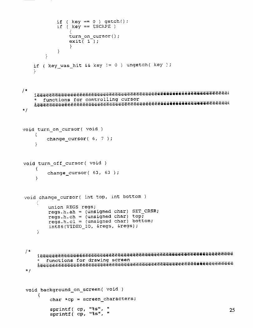
void turn on cursor( void )
{change_cursor( 6, 7 ) ;
}
void turn off cursor( void )
{change_cursor( 63, 63 ) ;
}
void change_cursor( int top, int bottom )
union REGS regs;
regs.h.ah = (unsigned char) SET_CRSR;
regs.h.ch = (unsigned char) top;
regs.h.cl = (unsigned char) bottom;
int86(VIDEO_IO, ®s, ®s) ;
/*
,/
void background_on_screen( void )
{char *cp = screen_characners;
"%s" "sprintf( cp,
sprintf( cp, "%s", "
25

sprintf ( cp, "%s", "
$printf( cp, "%s", "
$prinUf( cp, "%s", "
sprintf( cp, "%s", "
sprintf( cp, "%s", "
sprintf( cp, "%s", "
sprintf( cp, "%s", "
sprintf( cp, "%s" "
sprintf( cp, "%s" "
sprintf( cp, "%s" "
sprintf( cp, "%s" "
sprintf( cp, "%s" "
sprintf( cp, "%s" "
sprintf( cp, "%s" "
sprintf( cp, "%s" "
sprintf( cp, "%s", "
sprintf ( cp, "%s", "
sprintf( cp, "%s", "
sprintf( cp, "%s", "
_Heater i_¢O @
½C °o 1 o
½c
4
sprintf( cp, "%s", "Esc ... exit to dos
sprintf( cp, "%s", "S ..... set point command
sprintf ( cp, "%s", "A ..... set sensor averages
sprintf( cp, "%s", "F ..... save readings in a file
½C
3
Copper
fill_attribute_block( WHITE_ON I BLACK, 0, 24, 0, 79 ) ;
fill attribute block( WHITE ON I BROWN,
PLATE UL ROW, PLATE UL ROW + PLATE ROWS - i,
PLATE UL COLUMN, PLATE UL COLUMN + PLATE_COLUMNS - 1 );
fill attribute block( WHITE ON I BROWN,
HEATER1 UL-ROW, HEATERI--UL ROW + HEATER1 ROWS - l,
HEATERI--UL--COLUMN, HEATERI--UL COLUMN + HE--ATERI COLUMNS - 1 );
fill attribute block( WHITE ON I BROWN,
HEATER2 UL-ROW, HEATER2-UL ROW + HEATER2 ROWS - l,
HEATER2--UL--COLUMN, HEATER2--UL COLUMN + HEATER2_COLUMNS - 1 );N
fill attribute block( BLACK ON WHITE,
SENSOR1 UL-ROW, SENSORI--UL ROW + SENSOR1 ROWS - i,
SENSOR1 UL COLUMN, SENSSRI_UL_COLUMN + SENSORI_COLUMNS - 1 );
fill attribute block( BLACK ON WHITE,
SENSOR2 UL--ROW, SENSOR2--UL ROW + SENSOR2 ROWS - l,
SENSOR2--UL--COLUMN, SENSOR2--UL COLUMN + SENSOR2_COLUMNS - 1 );
fill attribute block( BLACK ON WHITE,
SENSOR3 UL--ROW, SENSOR3--UL ROW + SENSOR3_ROWS - l,
SENSOR3--UL--COLUMN, SENSOR3_UL_COLUMN + SENSOR3_COLUMNS - 1 );
26
fill attribute_block( BLACK ON WHITE,SENSOR4 UL ROW, SENSOR4--UL ROW + SENSOR4 ROWS - i,
SENSOR4 UL COLUMN, SENSOR4_UL_COLUMN + SENSOR4_COLUMNS - i );

fill antribute block( BLACK ON _ WHITE.SENSOR5UL--ROW, SENSOR5--ULROW+ SENSOR5ROWS- i,SENSOR5:UL_COLUMN,SENSOR5UL_COLUMN+ISENSOR5_COLUMNS- 1 );
fill attribute block( BRIGHT _HITE ON I BROWN,SENSOR1UL-ROW + i, SENSOR1UL-ROW+ 1 + SENSOR1ROWS- i,SENSORI-UL--COLUMN, SENSOR1UL COLUMN+ SENSOR1COLUMNS- 1 ) ;
fill a_tribute_block( BRIGHT _CHITEON I BROWN,SENSOR2UL ROW+ i, SENSOR2UL--ROW+ 1 + SENSOR2ROWS- i,SENSOR2UL COLUMN, SENSOR2UL COLUMN+ SENSOR2_COLUMNS- 1 );
fill attribute block( BRIGHT _HITE ON I BROWN,
SENSOR3 UL-ROW + l, SENSOR3 UL-ROW + 1 + SENSOR3 ROWS - l,
SENSOR3_UL_COtUMN, SENSOR3_UL_COLUMN + SENSOR3_COLUMNS - 1 );
fill attribute block( BRIGHT _HITE ON I BROWN,
SENSOR4 UL-ROW + l, SENSOR4 UL-ROW + 1 + SENSOR4 ROWS - i,
SENSOR4 UL COLUMN, SENSOR4 UL COLUMN + SENSOR4 COLUMNS - 1 ) ;
fill attribute block( BRIGHT WHITE ON I BROWN,
SENSOR5 UL ROW + i, SENSOR5 UL ROW + 1 + SENSOR5 ROWS - i,
SENSOR5-UL-COLUMN, SENSOR5 _L _OLUMN + SENSOR5 COLUMNS - 1 );
updatescreen();
void update screen( void )
display_screen () ;
}
void display_screen( void )
{/* Iraw the screen with the contents of the character and attribute
arrays */
int i;
char *ap = screen_attributes;
char *cp = screen characters;
unsigned char far *video_mem_ptr = (unsigned char far *) (0xB8OOL <<
for ( i = 0; i < 2000; ++i )
{*video_mem ptr++ = (unsigned char) *cp++;
*video_mem_ptr++ = (unsigned char) *ap++;
}
27

void write_string in screen buffer( char _strina int row,_ int column )
/* cop_y-the string to the specified location in the screen buffer
int location = _ow * 80 ÷ column;
while ( *string ){
screen_characters[ location++ ] = *string++;}
void write
{
_ouble in screen buffer( char *format string,
d_le _umber, int _ow, int column ) -
/* copy the double p_Qcision floating point number to the specified
location in the _reen buffer using the format string */
char string[80];
sprintf( string, format string, number );
writ%_string_in_screen_buffer( string, row, column );
void cut_string( char *destination, char *source, int first char, int last ch£
{ -- _
/* copy specified piece of character string from source todestination */
char * ptr;
for ( ptr = source + first_char; ptr <= source + last_char; ++ptr )*destination++ = *ptr;
*destination = O;
void user edit_field on screen( char *string,
int row, int start_column, int end column,
char field_foreground, char field_background,
char cursor_foreground, char cursor_background )
/* let the user edit a field on the screen and return the editted
field contents in the string */
int column, key = O, key2;
char saved_field_chars[lO0], saved_field_attrs[lO0], saved attr;
28
copy_characters_from_screen( saved_field_chars, row, row, start column
copy_attributes_from_screen( saved_field_attrs, row, row, start column
fill_attribute_block( field_foreground I field_background,
row, row, start_column, end_column );
column = start column;saved attr = screen a_tribu_esl row * 80 _ column ];screen a_tributes[ ?ow * 80 + column ] = cursor foreground I cursor ba
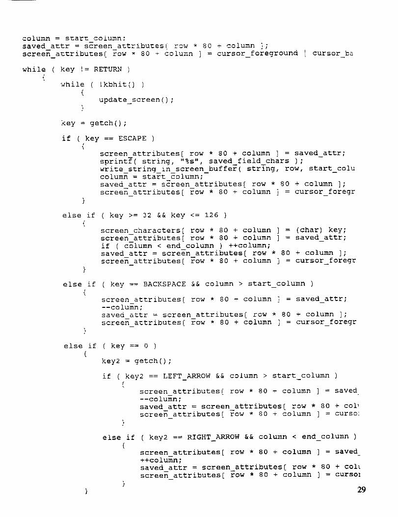
while ( key != RETURN ){
while (!kbhit() )
{update_screen () ;
}
key = getch() ;
if ( key == ESCAPE )
{screen attributes[ row * 80 + column ] = saved_attr;
sprintf( string, "%s", saved field chars ) ;
write string in screen_buffer( string, row, start_colucolumn = start _olumn;
saved attr = screen attributes[ row * 80 + column ];
screen attributes[ Tow * 80 + column i = cursor_foregr
else if ( key >= 32 && key <= 126 )
{screen characters[ row * 80 + column ] = (char) key;
screen-attributes[ row * 80 + column ] = saved_attr;
if ( column < end column ) ++column;
saved attr = screen attributes[ row * 80 + column ];
screen attributes[ row * 80 + column ] = cursor_foregr
else if ( key == BACKSPACE && column > start_column )
{screen attributes[ row * 80 + column ] = saved_attr;
--column;
saved attr = screen attributes[ row * 80 + column ];
screen attributes[ ?ow * 80 + column ] = cursor_foregr
else if ( key == 0 )
{key2 = getch() ;
if ( key2 == LEFT_ARROW && column > start_column )
screen attributes[ row * 80 + column ] = saved
--column;
saved attr = screen attributes[ row * 80 + colt
screen attributes[ row * 80 t column ] = curso:
else if ( key2 == RIGHT_ARROW && column < end_column )
{screen attributes[ row * 80 + column ] = saved_
++column;
saved attr = screen_attributes[ row * 80 + col[
screen attributes[ row * 80 + column ] = cursol
} 29
copy_characters_from_screen[ string, row, row, start_column, end_colu=
copy_attributes to screen( saved_field_attrs, row, row, start_column,
update_screen () ;
void copy characters from screen( char *string,int start roW, int end_row, int start_column, int end_column )
int row, column;
for ( row = start row; row <= end row; ++row )
for ( column _ start_column; _olumn <= end column; ++column )
*string++ = screen_characters[ row * 80 + column ];
*string = O;
void copy characters to screen( char *string,int start roW, Ynt end_row, int start_column, int end_column )
{int row, column;
for ( row = start row; row <= end row; ++row )for ( column _ start column; _olumn <= end column; ++column )
screen characters[ row * 80 + column ]--= *string++;
void copy attributes from screen( char *string,int star_ roW, int end_row, int start_column, int _nd_column )
int row, column;
for ( row = start row; row <= end row; ++row )
for ( column _ start_column; column <= end_column; ++column )
*string++ = screen_attributes[ row * 80 + column ];
*string = O;
void copy attributes to screen( char *string,int start roW, Ynt end_row, int start_column, int end_column )
{int row, column;
fo_ ( row = start row; row <= end row; ++row )for ( column _ start column; _olumn <= end column; ++column )
screen attributes[ row * 80 + column ]-= *string++;

void fill character block( char c,in_ star_ row, int end_row, ink s_ar__cc!umn, in_ _nd_column )
(int row, column;
for ( row = start row; row <= end row; ++row )
for ( column _ start column; _olumn <= end_column; ++column )
screen characters[ row * 80 + column ] = c;
void fill attribute_block( char c,
int start_row, int end_row, int start_column, int end_column )
{int row, column;
for ( row = start row; row <= end row; ++row )
for ( column _ start column; _olumn <= end_column; ++column )
screen attributes[ row * 80 + column ] c;
char query_user_for_key( char *prompt )
{/* Prompt the user for a single key response ./
char back characters[256], back attributes[256];
char front characters[256], front_attributes[256];
int length -= 0;
char * p = prompt, key = 0;
while ( *p++ ) ++length;
open window( back characters, back_attributes,
ROW_query_window,
ROW_query_window t 2,
COLUMN_query_window - length/2 - I,
COLUMN_query_window + length/2 + 5,
WHITE ON 1 BLACK );
openwindow( front characters, front_attributes,
ROW_query_window - i,
ROW_query_window + i,
COLUMN_query_window - length/2 - 3,
COLUMN_query_window + length/2 + 3,
BLACK ON I WHITE );
write_string_in_screen_buffer( prompt,ROW_query_window,
COLUMN_query_window - length/2 );
while ( !kbhit() ) update_screen();
key = (char) getch();
close window( front characters, front_attributes,
- ROW_query_window - i,
ROW_query_window + i,
COLUMN_query_window - length/2 - 3,
COLUMN_query_window + length/2 + 3 ) ;
3]

close window( back characters, back_a%tributes,
- ROW_query_window,
ROW_query_window ÷ 2,
COLUMN_query_window - length/2 - i,
COLUMN_query_window + length/2 + 5 );
update_screen();
return( key );
double query_user_for_number( char *prompt )
{/* Prompt the user for a number */
char back characters[256], back attributes[256];
char front characters[256], front_attributes[256];
int length -= 0;
char string[80], * p = prompt;
double number = 0.0;
while ( *p++ ) ++length;
length += i0;
open_window( back characters, back_attributes,
ROW_query_window,
ROW_query_window + 2,
COLUMN_query window - length/2 - i,
COLUMN query window + length/2 + 5,
ITE_SN I );
open_window( front characters, front_attributes,
ROW_query_window - i,
ROW_query window + i,
COLUMN_query_window - !engKh/2 - __r
COLUMN query window + length/2 + 3,
BLACKjN i W ITE);
write string in screen buffer( prompt,
.... ROW_query_window,
COLUMN_query_window - length/2 );
user edit field on screen( string,
.... ROW_query_window,
COLUMN_query window + length/2 - 7,
COLUMN_query_window + length/2 + I,BRIGHT WHITE ON, BLUE,
BRIGHT--WHITE--ON, BLACK ) ;
sscanf( string, "%if", &number ) ;
close window( front characters, front_attributes,
- ROW_query_window - i,
ROW query_window + i,
COLUMN_query_window - length/2 - 3,
COLUMN_query_window + length/2 + 3 ) ;
32 close_window( back_characters, back_attributes,

ROW_query_window.ROW_query window - _COLUMN_query window - length/2 - i,
COLUMN_query_window + length/2 + 5 ) ;
update_screen();
return( number );
void open window( char *character array, char *attribute array,int start row. int end row, int start_column, inE end_column,
char color_byte )
{/* open a blank window on the screen, saving the previous contents
in the character and attribute arrays */
copy characters from screen( character_array,- - - start row, end row,
start-column, end_column );
copy_attributes_from screen( attribute_array,- start_row, end_row,
start column, end_column ) ;
fill character block( ' ', start row, end row,- - star= column, end_column ) ;
fill attribute block( color_byte.- start row, end row,
start-column, end column ) ;
void close window( char .character array, char *attribute_array,
in{ start_row, int end_row, int start_column, int end_column )
{/* close a window on the screen, copying the contents of the
character and attribute arrays to the screen */
copy characters to screen( character_array,start_row, end_row,start column, end column );
copy attributes to screen( attribute_array,- - - start row, end row,
start-column, end column ) ;
33
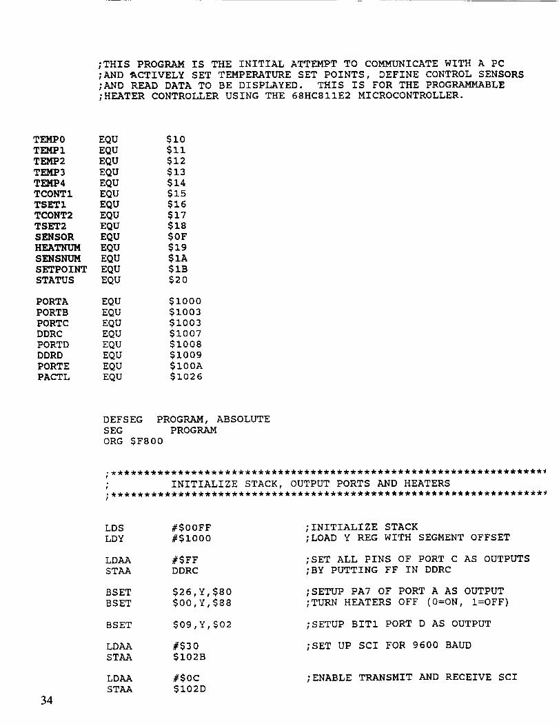
;THIS PROGRAM IS THE INITIAL ATTEMPT TO COMMUNICATE WITH A PC
;AND _CTIVELY SET TEMPERATURE SET POINTS, DEFINE CONTROL SENSORS
;AND READ DATA TO BE DISPLAYED. THIS IS FOR THE PROGRAMMABLE
;HEATER CONTROLLER USING THE 68HCSIIE2 MICROCONTROLLER.
TEMPO EQU
TEMPI EQU
TEMP2 EQU
TEMP3 EQU
TEMP4 EQU
TCONTI EQU
TSETI EQU
TCONT2 EQU
TSET2 EQU
SENSOR EQU
HEATNUM EQU
SENSNUM EQU
SETPOINT EQU
STATUS EQU
PORTA EQU
PORTB EQU
PORTC EQU
DDRC EQU
PORTD EQU
DDRD EQU
PORTE EQU
PACTL EQU
$i0
$Ii
$12
$13
$14
$15$16$17
$18$0F$19
$1A
$1B
$2O
$i000
$1oo3$1oo3$1oo7$1oo8$1009
$100A
$1026
DEFSEG PROGRAM, ABSOLUTE
SEG PROGRAM
ORG $F800
34
LDS #$00FF
LDY #$i000
LDAA #$FF
STAA DDRC
BSET $26,Y,$80
BSET $00,Y,$88
BSET $09,Y,$02
LDAA #$30
STAA $I02B
LDAA #$0C
STAA $I02D
;INITIALIZE STACK
;LOAD Y REG WITH SEGMENT OFFSET
;SET ALL PINS OF PORT C AS OUTPUTS
;BY PUTTING FF IN DDRC
;SETUP PA7 OF PORT A AS OUTPUT
;TURN HEATERS OFF (0=ON, !=OFF)
;SETUP BIT1 PORT D AS OUTPUT
;SET UP SCI FOR 9600 BAUD
;ENABLE TRANSMIT AND RECEIVE SCI

LDAA i039HORAA #80H
STAA I039H
:POWER ON A/D CONVERTERS
LDAA #$04
STAA PORTC
LDAA #$5E
STAA PORTB
;LOAD 12 BIT D/A WITH 2.73 VOLT VALUE
BSET $03,Y,$I0 ;SET GAIN OF PGA200 TO i0
; INITIAL CONDITIONS
LDAA #$03
STAA TCONTI
STAA TCONT2
LDAA #$30
STAA TSETI
STAA TSET2
_AINLOOP:
HEATERI:
I
; READ TEMPS 1-5
!
BCLR $00,Y,$70 ;THIS SELECTS MUXED
LDAB PORTA ;PUT PORTA IN BJSR READTEMP
STAA TEMPO
TEMP 0
ADDB #$i0 ;INCREMENT B TO
STAB PORTA ;SELECT TEMP SENSOR 1JSR READTEMP
STAA TEMPI
ADDB #$I0 ;INCREMENT B TO
STAB PORTA ;SELECT TEMP SENSOR 2JSR READTEMP
STAA TEMP2
ADDB #$i0 ;INCREMENT B TO
STAB PORTA ;SELECT TEMP SENSOR 3JSR READTEMP
STAA TEMP3
ADDB #$I0 ;INCREMENT B TO
STAB PORTA ;SELECT TEMP SENSOR 4JSR READTEMP
STAA TEMP4
"*********HEATERI
LDAB TCONTI
CLRA
XGDX ;LOAD TCONT1 IN X REG35

HI OFF:
HI ON:
HEATER2 :
H2 OFF:
H2 ON:
BRCLR $00,Y,$08,HI ON
LDAA TSETI
SUBA #$0A
SUBA SENSOR,X
BMI HEATER2
;IF BIT 3 IS 0 THEN BRANCH TO HI ON
;LOAD A WITH HEATER 1 SET POINT TEMP
;SUBTRACT 2 DEGREE
;SUBTRACT CONTROL1 SENSOR TEMPERATURE
BCLR $00,Y,$08BRA HEATER2
;TURN HEATER 1 ON
LDAA TSETI
SUBA SENSOR,XBPL HEATER2
;LOAD A WITH HEATER 1 SET POINT TEMP
;SUBTRACT CONTROL1 SENSOR TEMPERATURE
BSET $00,Y,$08 ;TURN HEATER 1 OFF
LDAB
CLRA
XGDX
TCONT2
;LOAD TCONT2 IN X REG
BRCLR $00,Y,$80,H2 ON
LDAA TSET2
SUBA #$0A
SUBA SENSOR,XBMI HEATEND
;IF BIT 0 IS 0 THEN BRANCH TO H2 ON
;LOAD A WITH HEATER 2 SET POINT TEMP
;SUBTRACT 2 DEGREE
;SUBTRACT CONTROL2 SENSOR TEMPERATURE
BCLR $00,Y,$80
BRA HEATEND;TURN HEATER 2 ON
LDAA TSET2
SUBA SENSOR,X
BPL HEATEND
;LOAD A WITH HEATER 2 SET POINT TEMP
;SUBTRACT CONTROL1 SENSOR TEMPERATURE
BSET $00,Y,$80 ;TURN HEATER 2 OFF
HEATEND :
HERE:
CHECKD:
H2STAT:
BRCLR $2E,Y,$20,HERE ;IF DATA RECIEVED BYTE NOT SET THEN
;GOTO NOBYTE
LDAA $I02F
CMPA #$44
BNE CHECKS
JSR SENDBYTE
;READ DATA RECEIVED
;CHECK IF BYTE IS "D"
;IF NOT "D" THEN GOTO CHECKS
;ECHO "D" BACK TO PC
CLRA
STAA
BRCLR
BSET
BRCLR
BSET
STATUS
$00,Y,$08,H2STAT
STATUS,S01
$00,Y,$80,SENDSTAT
STATUS,S02
;READ STATUS OF HEATER 1
;READ STATUS OF HEATER 2
SENDSTAT: LDAA
JSR36
STATUS
SENDBYTE
;SEND STATUS WORD

LDAA TEMPO :SEND SENSORTEMPERATURE0JSR SENDBYTE
CHECKS:
WAITHN:
WAITSN:
WAITSP:
FIGURE1:
FIGURE2:
LDAAJSR
LDAAJSR
LDAAJSR
LDAAJSR
JMP
CMPABNE
JSR
BRCLRLDAASTAAJSR
BRCLRLDAASTAAJSR
BRCLRLDAASTAAJSR
LDAACMPABEQLDAASTAALDAASTAA
/MP
LDAA
STAA
LDAA
STAA
TEMPI
SENDBYTE
TEMP2
SENDBYTE
TEMP3
SENDBYTE
TEMP4
SENDBYTE
NOBYTE
#$53
NOBYTE
SENDBYTE
$2E, Y, $20, WAITHN
$I02F
HEATNUM
SENDBYTE
$2E,Y,$20,WAITSN
$I02F
SENSNUM
SENDBYTE
$2E,Y,$20,WAITSP
$i02F
SETPOINT
SENDBYTE
HEATNUM
#$02
FIGURE2
SENSNUM
TCONTI
SETPOINT
TSETI
NOBYTE
SENSNUM
TCONT2
SETPOINT
TSET2
;SEND SENSOR TEMPERATURE 1
;SEND SENSOR TEMPERATURE 2
;SEND SENSOR TEMPERATURE 3
;SEND SENSOR TEMPERATURE 4
;CHECK TO SEE IF BYTE IS "S"
;IF NOT "S" THEN GOTO NQBYTE
;ECHO "S" BACK TO PC
;WAIT FOR HEATER NUMBER TO BE SENT
;READ HEATER NUMBER BYTE
;ECHO HEATNUM BACK TO PC
;WAIT FOR SENSOR NUMBER TO BE SENT
;READ SENSOR NUMBER BYTE
;ECHO SENSNUM BACK TO PC
;WAIT FOR HEATER NUMBER TO BE SENT
;READ SET POINT BYTE
;ECHO SETPOINT BACK TO PC
;IF HEATER #2 GOTO FIGURE2
NOBYTE: JMP MAINLOOP
37

; SENDBYTE SUBROUTINE
I
SENDBYTE: STAA
TWAIT: BRCLR
RTS
$I02F ;TRANSMIT BYTE FROM A REG
$2E,Y,$80,TWAIT ;WAIT FOR BYTE TO BE SENT
READTEMP :
NOTYETI:
NOTYET:
CLRA
LDAA # $ 0A
DECA
BNE NOTYETI
STAA $1030
LDAA #$06
DECA
BNE NOTYET
LDAA $1031
RTS
DEFSEG reset, ABSOLUTE
SEG reset
ORG SFFFE
DB $F8
DB $00
END
;SET A/D FOR SINGLE SCAN CHANNEL 0
;WAIT FOR MUX TO SETTLE
;AND START CONVERSION
;CONVERSION COMPLETE
;READ A/D RESULT
38

APPENDIX B
PHCC TEST PROCEDURES/RESULTS
39


Materials Required:
• 286 (or better) IBM-compatible PC with a 9-pin serial port
• 9-pin female computer cable wired as shown in figure 1
• PHC program disk with PHCCODE6.BIN, BOOT.BIN, HEATER.EXE, andPROGCOM1 .EXE.
• Bipolar 15-V power supply (i.e., +15 V and -15 V)
• 5-V power supply
• Variable 5-V power supply.
Special Notes:
External pin numbers, EP1 through EP29, may be different than used in the actual hybrid design.
Check the MSFC drawings to ensure connections are to the right points.
Computer Interface Set-Up:
Connect the computer corn 1 port to the hybrid circuit as shown in figure 1.
r
It
EP25
| 4| 9I
Note: Lines 1 and 6 may
need to be pulled high
through 3K resistors.
!
| DB9 Female Connector
Hybrid Circuit | (Attach to P.C.)!
Connections |.J
Figure 1.
Next, connect the power supplies to the appropriate pins as shown in figure 2; i.e., +15 V to EP26 andEP24, -15 V to EP27, +5 V to EP28, and GND to EP29 and EP25.
41
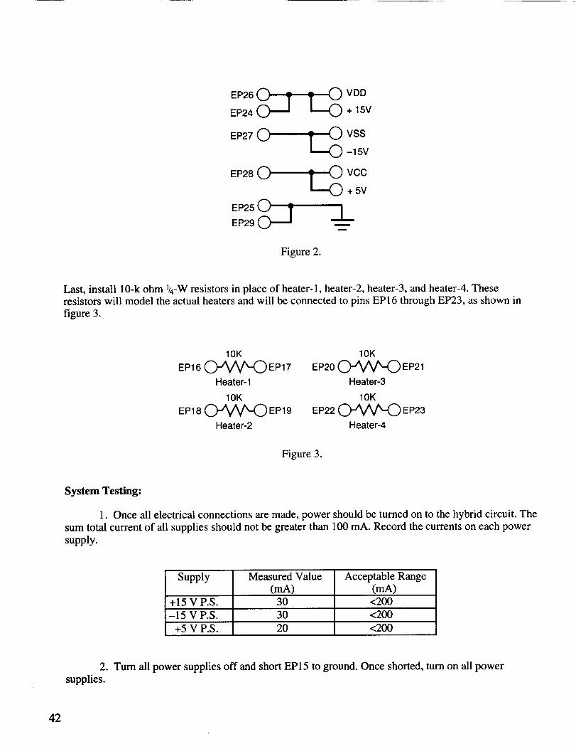
EP26 (_EP24
EP27 (_
EP28 (_)
EP25 (_EP29
_._ VDD+ 15V
_._ VSS-15V
VCC+ 5V
m
m
Figure 2.
Last, install 10-k ohm l/4-W resistors in place of heater-1, heater-2, heater-3, and heater-4. Theseresistors will model the actual heaters and will be connected to pins EP16 through EP23, as shown in
figure 3.
10K
EP16 (_"A__ EP17
Heater-1
10K
EP18 (_)-'_/_ EP 19
Heater-2
10K
EP20 _ EP21
Heater-3
10K
EP22 _ EP23
Heater-4
Figure 3.
System Testing:
l. Once all electrical connections are made, power should be turned on to the hybrid circuit. The
sum total current of all supplies should not be greater than 100 mA. Record the currents on each power
supply.
Supply Measured Value Acceptable Range(mA) (mA)
+15 V P.S. 30 <200
-15 V P.S. 30 <200
+5 V P.S. 20 <200
2. Turn all power supplies off and short EP15 to ground. Once shorted, turn on all power
supplies.
42

3. Insert PHC software disk in the PC and change the active drive to the one containing the
disk. At the proper disk prompt, type PROGCOM1 PHCCODE6.BIN. The computer screen should
appear as shown in figure 4 and the value for byte number automatically increment up to the value
shown in figure 4. Once this completes, the message 'eeprom code successfully transferred' will
display.
A:>progcom 1 phccode6.bin
The bootstrap code is 256 bytes.
byte #255 ...bootstrap successfully transferred.
The eeprom code is 2048 bytes.
byte #2047 ...eeprom code successfully transferred.A:>
Figure 4.
4. Remove the shorting wire on EP15.
5. Cycle all power supplies off and then on.
6. Type HEATER on the PC followed by a return. The screen should appear as shown in
figure 5.
Copper
n Enter 1 for COM1 or 2 for COM2 ]
Heater 3ESC ....... exit to dosS............ set point commandF............ save reading in a fileA............ set sensor averages
°C _ °CT8 T1
V---1 ocT2
Figure 5.
43
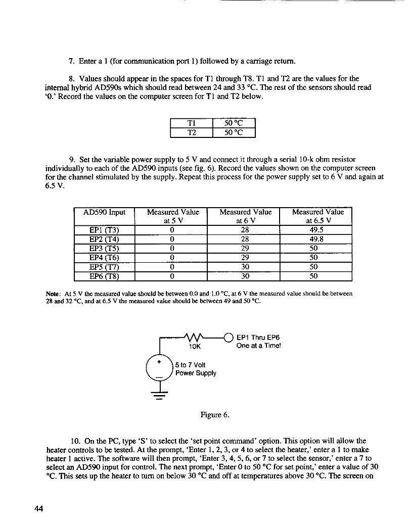
7. Enter a 1 (for communication port 1) followed by a carriage return.
8. Values should appear in the spaces for T1 through T8. T1 and T2 are the values for the
internal hybrid AD590s which should read between 24 and 33 °C. The rest of the sensors should read
"0.' Record the values on the computer screen for T1 and T2 below.
T1 50 °C
T2 50 °C
9. Set the variable power supply to 5 V and connect it through a serial 10-k ohm resistor
individually to each of the AD590 inputs (see fig. 6). Record the values shown on the computer screen
for the channel stimulated by the supply. Repeat this process for the power supply set to 6 V and again at6.5 V.
AD590 Input Measured Value Measured Value Measured Valueat5V at6V at 6.5 V
EP1 (T3) 0 28 49.5
EP2 (T4) 0 28 49.8
EP3 (T5) 0 29 50
EP4 (T6) 0 29 50
EP5 (T7) 0 30 50
EP6 (T8) 0 30 50
Note: At 5 V the measured value should be between 0.0 and 1.0 °C, at 6 V the measured value should be between28 and 32 °C, and at 6.5 V the measured value should be between 49 and 50 °C.
(m
m
EP1 Thru EP610K One at a Time!
5 to 7 VoltPower Supply
Figure 6.
10. On the PC, type'S' to select the 'set point command' option. This option will allow the
heater controls to be tested. At the prompt, 'Enter 1, 2, 3, or 4 to select the heater,' enter a 1 to make
heater 1 active. The software will then prompt, 'Enter 3, 4, 5, 6, or 7 to select the sensor,' enter a 7 to
select an AD590 input for control. The next prompt, 'Enter 0 to 50 °C for set point,' enter a value of 30
°C. This sets up the heater to turn on below 30 °C and off at temperatures above 30 °C. The screen on
44

thecomputershouldreflect theinformationin one of the four comers, depending on which heater isselected.
11. Using the same variable power supply setup as in step 9, set the voltage to 5 V and inject on
EP8. The computer screen should verify that the heater 1 is on by a different color block around the
heater. Hook a voltmeter to the heater 1 resistor (the meter should indicate 15 V). Slowly increase the
variable voltage supply (maximum of 7 V) until the heater 1 voltage drops to 0, as indicated on the
voltmeter. Verify that the computer screen also indicates the heater cutoff and record the voltage on the
variable supply at cutoff in the table below.
Heater
Heater 1Cutoff Voltage (V)
5.5051Acceptable Range (V)
2.9---) 3.1
12. Repeat steps 10 and 11 for the remaining three heaters using the same sensor and set point,
but choose a different heater. Remember to move the voltage meter to the active heater and record thevalues in the table below.
Heater
Heater 2Cutoff Voltage (V)
5.503
Heater 3 5.503
Heater 4 5.503
Acceptable Range (V)
45

6
7
5
8
4
93
10
211
112
1413
\
\T
1719
23
24
2726
2529
1528
20
181622
/Connections to Programmable Heater Controller Hybrid
Package P/U Numbers Correspond With EP Numberson Schematic
Argo Transdata Corp.
July 21, 1992
46

APPR 0 VAL
A PROGRAMMABLE HEATER CONTROL CIRCUIT FOR SPACECRAFT
by
D.D. Nguyen, J.W. Owen, D.A. Smith, and W.J. Lewter
The information in this report has been reviewed for technical content.
Review of any information concerning Department of Defense or nuclear energy
activities or programs has been made by the MSFC Security Classification Officer.
This report, in its entirety, has been determined to be unclassified.
Director
Structures & Dynamics Laboratory
_ _rL. Randall
ctor
Astrionics Laboratory


i
REPORT DOCUMENTATION PAGE _,m App_ov_OMB No. 0704-0188
e_e_tnf nf_'matmn n -'-_ .......... _Z._'f ........... _ ____"_ ........... " - uammems_J_lmmg1_n_our_mestlmo_oranyotheras!_ofl_is._..___-_.: ...... • _,r,y _,yy_-_uuv_ u. r'_'guung mlt w,,r_m, tO wasnmcj_n _elloqu,llf_et's _4BrvtcB, Oif_'[Ofllte 1'Or Irl_Oml_lO_ O_r'a'l_l_ and Rt,,,,_r.¢ :_, • t_,=..,,.-._
1. AGENCY USE ONLY (Leave blank) | 2. REPORT DATE 3. REPORT TYPE AND DATES COVERED
I • June 1994 Technical Memorandum
4. TITLE AND SUBTITLE IS. FUNDING NUMBERS
A Programmable Heater Controi Circuit for Spacecraft
(Center Director's Discretionary Fund Final Report Project No. 90-19)
6. AUTHOR(S)
D.D. Nguyen, J.W. Owen, D.A. Smith, and W.J. Lewter
7. PERFORMING ORGANIZATION NAME(S) AND ADDRESS(ES) 8. PERFORMING ORGANIZATION
REPORT NUMBER
George C. Marshall Space Flight Center
Marshall Space Flight Center, Alabama 35812
9. SPONSORING/MONITORING AGENCY NAME(S)AND ADDRESStES) 10. SPONSORING/MONITORING
AGENCY REPORT NUMBER
National Aeronautics and Space AdministrationWashington, DC 20546 NASA 12,I-I 08459
11. SUPPLEMENTARY NOTES
Prepared by Structures and Dyr.amics Laboratory and Astrionics Laboratory, Science and EngineeringDirectorate
12a. DISTRIBUTION / AVAILABILITY STATEMENT
Unclassified_Unlimited
Subject Category: 02
13. ABSTRACT (Maximum 200 words)
12b. DISTRIBUTION CODE
Spacecraft thermal control is accomplished for many components through use of multilayer insulation
systems, electrical heaters, and radiator systems. The heaters are commanded to maintain comFonent tempera-
tures within design specifications. The programmable heater control circuit (PHCC) was designed to obtain an
effective and efficient means of spacecraft thermal control. The hybrid circuit provides use of control instru-
mentation as temperature data, available to the spacecraft central data system, reprogramming capability of the
local microprocessor during the spacecraft's mission, and the elimination of sig'nificant spacecraft wiring. Thehybrid integrated circuit has a temperature sensing and conditioning circuit, a microprocessor, and a heater
power and control circuit. The device is miniature and housed in a volume which allows physical inte_ation
with the component to be controlled. Applications might include alternate battery-powered logic-circuit con-
figurations. A prototype unit with appropriate physical and functional interfaces was procured for testing. The
physical functionality and the feasibility of fabrication of the hybrid integrated circuit were successfully
verified. The remaining work to develop a flight-qualified device includes fabrication and testing of a Mil-
certified part. An option for completing the PHCC flight qualification testing is to enter into a joint venturewith industry.
14. SUBJECT TERMS
thermal condition, temperature control, reprogramming circuit
17. SECURITYCLASSIFICATION18. SECURITYCLASSIFICATION19. SECURITYCLASSIFICATIONOF REPORT OFTHIS.PAGE OFABSTRACT
Unclassified Unclassified UnclassifiedNSN7540-01-280-5500
15. NUMBER OF PAGES
5216. PRICE CODE
NTIS
20. UMITATION OF ABSTRACT
UnlimitedStandard Form 298 (Rev 2-89)P_ee,cnt=_-d by ANSI S_ Z39-182gB._o_


![Spacecraft Simulation]](https://static.fdocuments.us/doc/165x107/544e0a73b1af9f33638b4bf0/spacecraft-simulation.jpg)