A Practical Assessment of Network Orientated Load …doras.dcu.ie/18272/1/Navinder_Singh_Wathan.pdfA...
139
A Practical Assessment of Network Orientated Load Control for the Intelligent Network by Navinder Singh Wathan, BEng Thesis submitted as a requirement for the attainment of the degree of Masters of Engineering Supervised by Prof. Thomas Curran School of Electronic Engineering, Dublin City University October 2003
Transcript of A Practical Assessment of Network Orientated Load …doras.dcu.ie/18272/1/Navinder_Singh_Wathan.pdfA...

A Practical Assessment of Network Orientated Load Control for the
Intelligent Network
by
Navinder Singh Wathan, BEng
Thesis submitted as a requirement for the attainment of the degree ofMasters of Engineering
Supervised by Prof. Thomas Curran
School of Electronic Engineering, Dublin CityUniversity
October 2003

1 hereby certify that this material, which I now submit for assessment on the programme of study leading to the award of MSc in Telecommunication is entirely my own work and has not been taken from the work of others save and to the extent that such work has been cited and acknowledged within the text of my work
Date: /-xotx-t- .

TABLE OF CONTENTS
1 INTRODUCTION........................................................................... 1
1.1 M o t i v a t i o n ......................................................................................................................................................1
1.2 O b j e c t iv e s .........................................................................................................................................................1
1.3 M e t h o d o l o g y ...............................................................................................................................................1
1.4 S t r u c t u r e ........................................................................................................................................................ 2
2 THE INTELLIGENT NETWORK................................................. 2
2.1 In t r o d u c t io n ................................................................................................................................................. 2
2 .2 H i s t o r y ..............................................................................................................................................................3
2 .3 T h e C o n c e p t u a l M o d e l .........................................................................................................................5
2 .4 E x a m p l e S e r v ic e Im p l e m e n t a t io n s ............................................................................................11
2 .5 C u r r e n t a n d F u t u r e R o l e O f T h e in t e l l ig e n t N e t w o r k ........................................ 17
2 .6 L o a d C o n t r o l M e c h a n is m s ..............................................................................................................17
2 .7 S u m m a r y ........................................................................................................................................................ 2 0
3 THE INTELLIGENT NETWORK MODEL................................ 21
3 .1 In t r o d u c t i o n ...............................................................................................................................................21
3 .2 S t r u c t u r e a n d O p e r a t io n ................................... 2 3
3 .3 S u m m a r y ........................................................................................................................................................ 2 7
4 NETWORK ORIENTATED LOAD CONTROL: THEMARINER SYSTEM................................................................. 28
4 .1 In t r o d u c t i o n ...............................................................................................................................................2 8
4 .2 T h e o r e t ic a l D e s c r ip t io n ................................................................................................................... 3 0
4 .3 I m p l e m e n t a t i o n ........................................................................................................................................4 3
4 .4 S u m m a r y ........................................................................................................................................................ 4 7
5 EXPERIMENTS AND RESULTS.............................................. 49
5.1 In t r o d u c t i o n ...............................................................................................................................................4 9
5 .2 E x p e r im e n t a l S e t u p ...............................................................................................................................5 2
5 .3 In t e g r a t io n E x p e r im e n t s .................................................................................................................. 5 5
iii

5 .4 E v a l u a t io n E x p e r im e n t s ................................................................................................................... 5 9
5 .5 R o b u s t n e s s E x p e r i m e n t s ...................................................................................................................7 6
5 .6 S u m m a r y .........................................................................................................................................................8 7
6 CONCLUSION AND FUTURE WORK......................................89
6.1 In t r o d u c t io n ............................................................................................................................................... 8 9
6 .2 S t a n d a r d IN L o a d C o n t r o l ...........................................................................................................9 0
6 .3 G l o b a l IN C o n t r o l S t r a t e g y .......................................................................................................9 2
6 .4 A u t o m a t ic C a l l R e s t r ic t io n ......................................................................................................... 9 3
6 .5 T h e M A R IN E R S y s t e m .........................................................................................................................9 4
6 .6 L o a d C o n t r o l S y s t e m C o m p a r i s o n .......................................................................................... 9 7
6 .7 C o n c l u s i o n ................................................................................................................................................... 9 8
6 .8 F u t u r e W o r k ............................................................................................................................................... 9 9
GLOSSARY............................................................................................. 101
REFERENCES.........................................................................................103
APPENDIX A: MARINER INFORMATION FLOWS.............................108
APPENDIX B: IN MODEL.......................................................................110
B .l S S F ..................................................................................................................................................................... 1 10
B .2 S C F ..................................................................................................................................................................... 1 16
B .3 T r a f f ic G e n e r a t o r ............................................................................................................................... 1 22
B .4 S e r v ic e E x e c u t i o n .................................................................................................................................124
APPENDIX C: MARINER SYSTEM.......................................................127
C .l R A A ...................................................................................................................................................................127
C.2 RMA........................................................................................................................130

A Practical Assessment of Network Orientated Load Control for the Intelligent Network
MEng Thesis by Navinder Singh Wathan
Abstract
The purpose o f this thesis is to assess a new method o f controlling load in Intelligent
Networks (INs). This will be done through the analysis o f experimentation results and
comparison with existing methods o f IN load control. This exercise will result in the
investigation and validation o f the proposed benefits being offered by this new
methodology and the unveiling of its disadvantages. The methodology is known as
network-orientated load control for the IN.
Network-orientated load control is demonstrated using the MARINER Service Traffic
Load Control System developed by the European Commission’s Advanced
Communication, Technologies and Services (ACTS) Multi-Agent Architecture for
Distributed Intelligent Network Load Control and Overload Protection (MARINER)
Project. This system is shown to be a network-orientated load control application
operating at the service level, built specifically for Intelligent Networks.
Network-orientated load control is then assessed by deploying the MARINER System on
a model o f the IN, and running an exhaustive series of experiments. These experiments
are structured to test the proposed benefits, limitations and disadvantages o f network-
orientated load control.
The conclusions drawn from the results o f these trials are then compared with existing IN
load control characteristics, and used to make an assessment o f network-orientated load
control for the Intelligent Network.

Acknowledgements
I would like to thank Prof. Thomas Curran and the IN Group at Teltec for the invaluable
guidance, support and friendship they have given me throughout my work on this project.
Further, I would like to thank the MARINER Group as a whole, for all the input and
motivation they gave me in reaching the completion of this project.
I would also like to thank my family, my friends and Jasvin for making sure I saw this
through to the end. And also my gratitude to Moby, Nustrat Ali Khan and David Gray for
providing the music that allowed me to focus on this.
Finally, I would like to thank you, the reader, for acknowledging my work by attempting
to assimilate it and possibly re-using it.
Thank you all.

1 INTRODUCTION
1.1 M o t iv a t io n
The purpose o f this thesis is to assess a new method of controlling load in Intelligent
Networks (INs). This will be done through the analysis o f experimentation results and
comparison with existing methods o f IN load control. This exercise will result in the
investigation and validation of the proposed benefits being offered by this new
methodology and the unveiling o f its disadvantages. The methodology is known as
network-orientated load control for the IN.
This document is suitable for both newcomers to the field o f Intelligent Networks and
Load Control, as well as experts interested in new methods o f the application o f Load
Control to Intelligent Networks.
1.2 O b jec tive s
The objectives o f this body o f work are as follows:
• The introduction and demonstration o f network-orientated load control for the IN
• The validation of network-orientated load control through experimentation
• The comparison o f network-orientated load control to existing IN load control
methodologies
• The investigation o f the limitations and disadvantage o f network-orientated load
control
1.3 M e t h o d o l o g y
As a means o f introducing and demonstrating network-orientated load control, the
MARINER Service Traffic Load Control System developed by the European
Commission’s Advanced Communication, Technologies and Services (ACTS) Multi-
Agent Architecture for Distributed Intelligent Network Load Control and Overload
1

Protection (MARINER) Project [MARINER] is used. The MARINER System is a
network-orientated load control application operating at the service level, built
specifically for Intelligent Networks.
Further, in order to accurately assess the operation o f network-orientated load control, a
model o f the IN is used. This model emulates the operation existing Intelligent Networks
conforming to the International Telecommunication Union IN Capability Set 2 [Q1200]
standard.
The benefits, limitations and disadvantages of network-orientated load control is then
investigated using an exhaustive set o f trials on the IN model, with the MARINER
System applied to it.
The conclusions drawn from the results o f these trials are then compared with existing IN
load control characteristics.
1.4 St r u c t u r e
Chapter 2 introduces the Intelligent Network. This introduction includes a brief history
o f its development followed by a theoretic description o f the Intelligent Network
Conceptual Model (INCM). These descriptions are then enhanced by examples o f
existing service implementations. The chapter then explains the role o f the Intelligent
Network in today’s context, and then focuses on load control elements o f the INCM in
line with the objectives o f this document. An example o f an Intelligent Network
overload, occurring in April 2000, is then given as a means of analysing the operation
and effectiveness o f these load control elements in ‘real’ environments. Finally, the
chapter concludes with a summary. Readers familiar with the Intelligent Network need
not read this chapter.
Chapter 3 describes the Intelligent Network model used as the trial platform for the
network-orientated load control methodology. It goes through the motivation and
objectives o f the model, as well as its design and development. This is followed by a
description o f the model structure and operation. A summary o f the chapter is then
presented.
2

Chapter 4 introduces the MARINER Service Traffic Load Control System as an
implementation o f network-orientated load control for Intelligent Networks. A
description o f the motivation and objectives o f both network-orientated load control and
the MARINER System is given. This is followed by a theoretical description o f the
operational algorithm and the system operation. Then a treatment o f the implementation
o f the system is given, before the chapter is summarized.
Chapter 5 describes the experiments that were carried out on the MARINER System and
their results. First, the experiment setup is described. This is followed by descriptions o f
the experiments and their results. These descriptions are categorized into three groups;
the integration experiments, which investigate the validity o f the MARINER System as a
network-orientated load control system, and its integration to the IN.; the evaluation
results, which evaluate the various aspects of the MARINER System; and the robustness
experiments, which explore the limitations of the MARINER System. The chapter is
then summarized.
Chapter 6 compares network-orientated load control to existing IN load control
mechanisms and presents the conclusions o f this body of work. First, the MARINER
System is compared with three representative load control methodologies using the
criteria and conclusions put forth in Chapter 5. Then, the thesis conclusions are
presented, followed by a brief description o f the future work to be carried out based on
these conclusions.
3

2 THE INTELLIGENT NETW ORK
2.1 I n t r o d u c t io n
The Intelligent Network (IN) is an architectural concept that provides for the real time
execution of network services and customer applications in a distributed environment o f
interconnected computers and switching systems. Its definition also includes support for
the creation, implementation and management o f these services and applications
[Fayn96].
Instead o f supporting the building o f customised, performance-intensive services, it was
realised quite early on that the IN would be much more useful and universally acceptable
if it adhered to certain principles o f independence. Namely,
• Service independence. The IN supports all services that use the common service
independent building blocks (SIBS - see § 2.3.2). Among the current IN services are
the Freephone service, the Virtual Private Network (VPN) service, the Ringback
service and the Account Card Calling service.
• Switch independence. The IN maintains a clear logical separation between the
service execution functions, and the basic switching functions.
• Network independence. Although first developed for the public switched telephone
network (PSTN), the IN concept is applicable to several different types of networks,
which include the mobile communications network, packet switched public data
network (PSPDN), integrated service digital network - both narrow-band (N-ISDN)
and broad-band (B-ISDN).
The rest o f this chapter will provide a basic introduction to the Intelligent Network. First,
a brief history is detailed. This is followed by a description o f the Intelligent Network
Conceptual Model. Then, examples o f IN service implementations using this model are
described. Following this is a section on the current and future role of the IN, followed
by a focus on its load control abilities. Then, the chapter summary is presented.
2

It was not until 1986 that the phrase “Intelligent Network” had come to be associated
with the architectural concept described above. However, its roots lie in the 1960s, when
the first Stored Program Control Exchanges were deployed and introduced computer
technology into the telecommunication network. These systems could support services
such as Call Forwarding, Call Waiting and Centrex on a local level.
By the late 60s, rudimentary 800 number services, such as the Inward Wide Area
Telecommunication Service (INWATS), were already available in long distance
networks. These services were deployed on crossbar switches, which made
implementation complex and cumbersome. In 1976, the advent o f the first electronic
switches in the AT&T long distance network greatly eased this burden.
However, it was only in the mid 70s, that the key innovation for IN was first deployed.
The Common Channel Signalling No 6 (CC6, which was known as Common Channel
Interoffice signalling or CCIS in the US) was initially used only for the transmission o f
address digits and trunk status information. It was soon proposed that the signalling
system be used for communication between a network database and the switches in the
network, and this laid the foundation for the IN concept.
In the early 80s, the concept saw fruition when two services based on it; the Calling Card
and 800 number service (CCIS INWATS) were deployed. This development triggered
work at Bell Labs o f the US towards creating an open platform with primitive messaging
between the switch and the service execution entity, which could be used to create
different services. The initial result o f these activities was the Direct Service Dialling
Capabilities (DSDC) architecture and the first services implemented on it were the 800
number service and the Software Defined Network (SDN), the predecessor o f the Virtual
Private Network service. This architectural concept soon spread all over the globe, with
France and Germany introducing the Freephone service in 1983 and the UK in 1985,
using AT&T products. In Japan, NTT implemented its own Freephone service in 1985.
In 1984, Bell Systems was dissolved into the Regional Bell Operating Companies
(RBOCs). As a result, Bellcore (the research company associated with the RBOCs)
began work on the total separation o f service features from the switching process,
2.2 H ist o r y
3

particularly influenced by the RBOCs multiple-vendor equipment supply. This first IN
endeavour at the local network level resulted in a version of IN called IN2 which, while
being very ambitious, was never realised. Then the Multivendor Interactions Forum was
formed to include the many equipment vendors in the development process. What came
out o f it was the Advanced Intelligent Network (AIN) which is being implemented in the
US in small steps (AIN 0.1 was launched in 1992) [Vasic99].
In 1989, the International Consultative Committee for Telegraph and Telephone (CCITT,
now International Telecommunication Union or ITU-T) and the European
Telecommunication Standardisation Institute (ETSI) started work on the standardisation
o f IN. A phase structured development process was started, which aimed to completely
define the target IN architecture. Each phase of development intended to define a
particular set o f IN capabilities, known as Capability Sets, which contained the services
and service features that could be constructed with the available functionality at that
particular evolution of the IN. In March 1992, the first capability set (CS-1) was
approved, but a revised version was released in 1995, known as CS-1R. Currently, the
latest approved version is the CS-2.
4

The Intelligent Network Conceptual Model (INCM) was designed to incorporate the
concepts which define the IN. In itself, it should not be considered to be an architecture,
but rather a model for the design and description o f Intelligent Networks [Q1201].
The INCM offers four different views o f the IN, each on a different level o f abstraction -
called a “plane” - and defines the mapping between those views. These planes are
depicted in Figure 2.1 [Q1201], each representing a different aspect o f service building.
The two upper planes focus on service creation and implementation, whereas the lower
two planes addressing the physical IN architecture.
2.3 T h e C o n c e p t u a l M o d e l
5

2.3.1 Service Plane (SP)
This is the uppermost plane o f the INCM, which offers the most abstract view o f the
Intelligent Network. It describes services from the user’s perspective, and is not
concerned with how the services are implemented within the network. The services are
composed of one or more service features, which may either be core features that carry
the main functionality o f the service, or optional parts offered as enhancements to the
telecommunication service [Q1202] [Q1222].
2.3.2 Global Functional Plane (GFP)
The plane second from the top presents a view demonstrating the IN view o f service
creation by putting together modules o f reusable network functionality. It does not
include a view o f the network and its details. These “modules o f reusable network
functionality” are called Service Independent Building Blocks (SIBs) and have formal
descriptions that include service-specific and instance-specific parameters, possible
execution outcomes and results, as well as errors that may occur.
The Basic Call Process (BCP) is a special SIB that is invoked for all calls, and handles
basic connectivity. Services in the SP are described in the GFP in terms o f the point at
which the BCP should be interrupted (Point o f Initiation or POI), the chain o f SIBs that
need to be executed, and the point at which the BCP is resumed once the IN-specific
processing is completed (Point o f Return or POR). Figure 2.2 illustrates service
description in the GFP [Q 1203] [Q1223].
6

This plane offers a view of the network as a collection o f Functional Entities (FEs). The
physical location o f these functional entities is not visible. Each FE can perform a
number o f Functional Entity Actions (FEAs) and the FEs communicate by sending
Information Flows (IFs) to each other. The FEAs are further broken up into Elementary
Functions (EFs). SIBs in the GFP are realised in the DFP by a sequence FEAs and their
resulting IFs. Figure 2.3 depicts the IN DFP Model [Q1204][Q1224].
2.3.3 Distributed Function Plane (DFP)
CCAF - Call Control Agent FunctionCCF - Call Control FunctionSCEF - Service Création Environment FunctionSCF - Service Control FunctionSDF - Service Data FunctionSMAF - Service Management Access FunctionS MF - Service Management FunctionSRF - Service Resource FunctionSSF - Service Switching Function
Figure 2.3 - The IN Distributed Function Model
7
• The Call Control Agent Function (CCAF) provides the user with access to the
network and serves as an agent between the user and the service-providing
capabilities o f the Call Control Function.
• The Call Control Function (CCF) carries the basic call and/or connection
functionality, acting at the request o f the CCAF. It provides triggers for accessing IN
functionality.
• The Service Switching Function (SSF) processes the triggers received from the CCF
and identifies the service control triggers. It manages the signalling between the CCF
and the SCF and modifies the call processing in the CCF, when requested by the SCF.
The CCF and SSF are tightly coupled and are usually implemented together. The
reason they are maintained as separate FEs is that the SSF is used to represent the IN-
specific part o f the switching functionality. The CCF, on the other hand, represents
the non-IN, basic call processing functionality.
• The Service Control Function (SCF) is the central functional entity o f the IN. It
controls the execution o f IN implemented services. It performs service processing
primarily through the communication with the SSF, from which requests for
processing arrive and to which the SCF sends related call control instructions. The
SCF also interacts with SDF to get or set network-stored information required by the
service and with the SRF when special resources are required.
• The Service Data Function (SDF) contains customer and network data and is queried
by the SCF during service processing.
• The Service Resource Function (SRF) contains specialised hardware resources
required for IN services, mainly for user interaction, such as announcement players,
tone generators, voice recognition and digit collection devices. Other SRFs include
text to speech synthesisers, protocol converters and conference bridges. It is
controlled during service processing through interactions with the SCF.
The FEs related to service creation and management are described below:
The following FEs are related to the execution o f IN services:
8
• The Service Creation Environment Function (SCEF) provides an environment for the
definition, development, testing and online deployment o f services.
• The Service Management Access Function (SMAF) is the equivalent o f the CCAF in
the service management domain o f the IN. It provides managers with access to the
SMF.
• The Service Management Function (SMF) allows the deployment and provision o f IN
services and manages and updates most o f the other FEs (CCF, SSF, SCF and SDF).
It also provides online management functions, such as the collection o f billing and
statistical information.
2.3.4 Physical Plane (PP)
On the physical plane, a full view o f the physical network is available. It shows the
Physical Entities (PEs) present in the network and where the functional entities are
located, in terms o f physical entities. The PEs associated with IN service execution are
as follows:
• The Service Switching Point (SSP) is a switch that contains the CCF and the SSF. In
the case that it is a local exchange, it also contains the CCAF
• The Service Control Point (SCP) contains the SCF and may also contain the SDF.
• The Service Data Point (SDP) contains the SDF.
• The Intelligent Peripheral (IP) contains the SRF and possibly a CCF/SSF to provide
external access to its switching matrix.
The service creation and management PEs are listed below:
• The Service Management Point (SMP) contains the SMF and possibly the SMAF
when the manager is working directly on the SMP machine. It may also include the
SCEF.
• The Service Creation Environment Point (SCEP) contains the SCEF.
• The Service Management Access Point (SMAP) contains the SMAF. It is a point of
access for a manager to the SMP and behaves like a terminal attached to the SMP.
9

There are three other PEs defined in for the IN which, unlike those listed above, do not
have a one-to-one mapping with a FE.
• The Adjunct (AD) operates somewhat like the SCP, with the exception that it is
directly connected to the SSP without a signalling network separating the two. The
AD is used mainly when high-speed communication between the two entities is
required.
• The Service Node (SN) is similar to the AD in that it is directly connected to an SSP.
However, apart from a SCF, it also contains a SDF, SRF and a CCF/SSF. The
CCF/SSF is not accessible from outside the SN, while the SRF has such accessibility.
The SN may be used as any other IP by any SCF.
• The Service Switching and Control Point (SSCP) combines the SSP and SCP in one
node. It contains the SCF, SDF, CCAF, CCF SSF and possibly the SRF. Although
the functionality provided is the same as that o f a separate SSF and SCF, the
interfaces between these FEs within the SSCP are proprietary [Q1205].
An important aspect o f this view o f the IN is the definition o f protocols, which are used
for the communication between PEs, depending on which FEs they contain. The protocol
used is known as the Intelligent Network Application Protocol (INAP). It is a user o f the
Remote Operations Service Element (ROSE) protocol, which contains primitives suitable
for communication between physically remote entities and is standardised through the
ITU-T recommendations X.219 and X.229. ROSE, in its turn, is contained in the upper
layer o f the Transaction Capabilities Application Part (TCAP) [Q771]. TCAP may use
the lower layers o f most protocols for network layer functionality, and in the case of
INAP, the SS7 signalling stack is used [Q1208] [Q1228].
10

This section introduces the possible implementations of three IN services using the four
views described in the INCM. These services are also those that were implemented in the
IN Model described in Chapter 3.
2.4.1 The Restricted User Service
2.4.1.1 SP View
Basic call forwarding allows the user to redirect incoming calls to a different number
transparent to the calling party. The Restricted User Service is a variation o f this service,
in which the calling party must enter a specified Personal Identification Number (PIN)
before the call is forwarded to the other number [MARINERD4].
2.4.1.2 GFP View
This service comprises the following SIBs:
• Basic Call Processing (BCP) - Initial Message Flows
This SIB sets a trigger for incoming calls to the service user. In the event o f an
incoming call, the SIB initiates the chain o f SIBs required to execute this service.
• User Interaction
This SIB prompts the calling party for the PIN number, and collects the digits.
• Verify
This SIB verifies the PIN number.
• BCP - Call Setup
This SIB connects the calling party to the forward destination.
2.4 E x a m pl e Se r v ic e Im p l e m e n t a t io n s
11
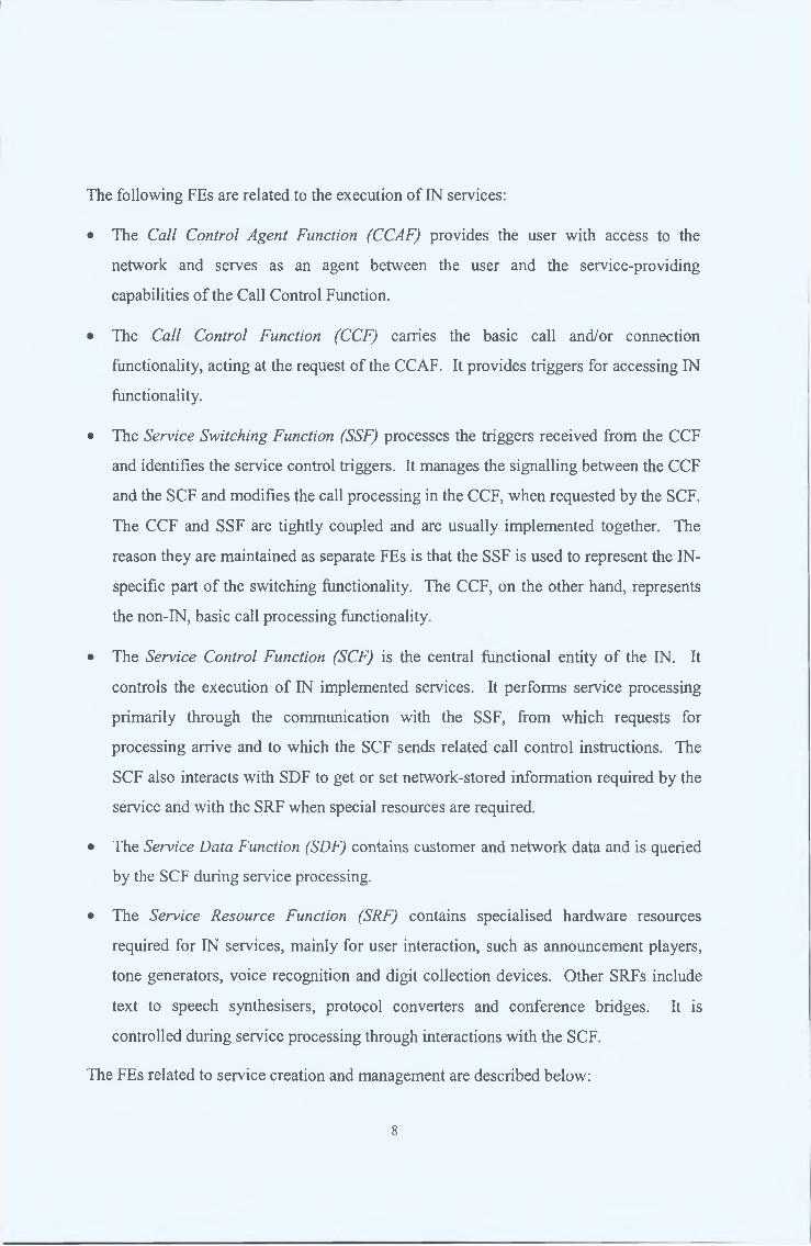
2.4.1.3 DFP View
The DFP view for this service is illustrated by the Inform ation Flows betw een the
Functional Entities in Figure 2.4.
SRF SSF SCF
VInitia ID P
ConnectToResource
Setup wSetup (Conf)
Pro mpt& Col lectUserln fo
User InteractionPlayAnnouncement
PACULResult
CancelAnnouncement
ReleaseConnect
Figure 2.4 — Information Flows of Restricted Access Call Forwarding Service
2.4.1.4 PP View
The Physical Entities utilised for this service are the IP, SSP and SCP.
12

2.4.2 The VPN Service
2.4.2.1 SP View
The VPN Service creates a logical sub-network spanning a single or multiple IN network
domains, which appears to a specific group of users as a private network, providing the
type of services normally associated with private exchanges [MARINERD4].
2.4 .2.2 GFP View
This service comprises the following SIBs:
• Basic Call Processing (BCP) - Initial Message Flows
This SIB arms a trigger for users who initiate this service during call processing.
When the trigger is encountered, the SIB initiates the chain o f SIBs required to
execute this service.
• Status Notification
This SIB captures the private number o f the called party input by the calling party.
• Translate
This SIB checks the private number against the network database and gets the
network number of the called party
• BCP - Call Setup
This SIB connects the two parties. It them monitors for an off-hook by the calling
party and ends the service processing.
13

2.4.2.3 DFP View
The DFP view for this service is illustrated by the Information Flows betw een the
Functional Entities in Figure 2.5.
SDF SSF SCF
wInitialDP
ReqEventReportBCSM wEventReportBCSM
Search
Search (Results)w
aConnect w
EventReportBCSM
User Interaction
wEventReportBCSM
ReleaseCall
Figure 2.5 - Information Flows of VPN Service
2.4.2.4 PP View
The Physical Entities utilised in the VPN service are the SDP, SSP and SCP.
2.4.3 The A utom ated Ring back Service
2.4.3.1 SP View
This service allows a calling party, upon receipt of an engaged tone for a specific called
party, to request that a call be automatically initiated to that called party once their
present call has been terminated [MARINERD4].
14

• Basic Call Processing (BCP) - Initial Message Flows
This SIB arms a trigger for users who initiate this service during when the engaged
tone is encountered. When trigger is set off, the SIB initiates the chain o f SIBs
required to execute this service.
• User Interaction
This SIB informs the calling party that the ringback service is in operation.
• BCP - Event Report
This SIB monitors for the termination of the called party’s present call.
• BCP - Call Initiation
This SIB initiates a call to the called party and monitors for an off-hook.
• BCP - Call Setup
This SIB re-connects to the calling party and monitors for an off-hook.
• BCP-Call Setup
This SIB returns both parties to normal call processing.
2.4.3.2 GFP View
This service comprises the following SIBs:
15
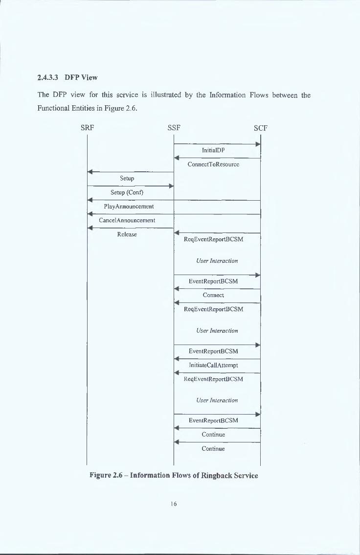
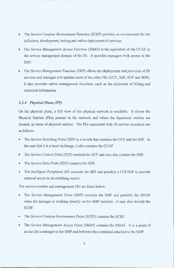
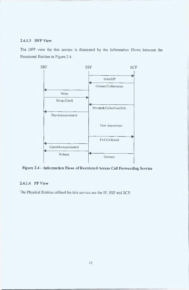
2.4.3.3 DFP View
The DFP view for this service is illustrated by the Information Flows betw een the
Functional Entities in Figure 2.6.
SRF SSF SCF
InitialDP
ConnectT oResource
Setup wSetup (Conf)
PlayAnnouncement
CancelAnnouncement
ReleaseReqEventReportBCSM
User Interactionw
EventReportBCSM
Connect
ReqEventReportBCSM
t/ser InteractionEventReportBCSM
InitiateCallAttempt
ReqEventReportBCSM
User Interactionw
EventReportBCSM
Continue
Continue
Figure 2.6 - Information Flows of Ringback Service
16

The Physical Entities utilised in the Automatic Ringback service are the IP, SSP and
SCP.
2.5 C u r r e n t a n d F u tu r e R o le O f T h e in t e l l ig e n t N e t w o r k
Today, more than 80% [Mine98] o f the PSTN operators use the IN, or one o f its
derivatives, to execute telecommunication services. These services range from,
Automated Ringback to Telebanking.
With the IN having had the lion’s share o f investment and customer trust for so long,
operators moving to wireless technologies such as GSM and GPRS, as well as Internet
Telephony, want to maintain the IN as the de facto telecommunication service execution
architecture. Research projects such as the EURESCOM’s P916 [P916] and ETSI’s
TIPHON [TIPHON] are currently attempting to standardise methods in which this can be
achieved.
2.6 L o a d C o n tr o l M e c h a n is m s
The IN CS-2 provides two mechanisms for controlling the traffic going into an SCF, in
the event o f congestion. These are Call Gapping and the Service Filter SIB [Q1224].
• Call Gapping - This mechanism is activated by the SCP, upon congestion, by sending
a Call Gap request to the SSP. It involves the use o f a timer set to expire after a gap
interval g. For each call arriving at the switch, the gap interval timer is checked. If
the timer is inactive, the call is accepted and the timer is set. Until this timer expires,
all further arriving calls will be unconditionally blocked. After the gap interval has
elapsed and the timer is inactivated, the first call to arrive is accepted and serviced
and the gap interval timer is set again. This mechanism is illustrated in Figure 2.6
[Tsolas92].
2.4.3.4 PP View
17

Call requests
to switch
Key:
Accepted call: \
Blocked call: ^
/ /
h ---------------- Hg
Figure 2.9 - Call Gapping Mechanism
• Service Filter SIB - the SIB limits the number o f calls that are allowed through an IN
by filtering calls with given characteristics. The filtering is applied only to those calls
related to IN-provided service features that request the assistance o f IN functions.
Calls are blocked at the SSP and provided treatment for a specified duration (which
may be infinite) at specified intervals. Service Filter is initiated by the subscriber.
These mechanisms have the following characteristics:
■ reactive - they react to a resource overload after it has commenced, rather than
ensuring that traffic is prevented from gaining access to the resource in instances
where it would cause one or more resources to overload. More predictive controls
that ‘see’ and control overloads as it approaches would be more efficient;
■ node-oriented - they aim to protect individual resources from overload. Lack o f
interaction between independent controls can have undesirable effects, such as the
propagation o f overload throughout the network. A network-oriented approach, where
control decisions are co-ordinated in a manner that ensures optimal performance o f
the network as a whole would be more desirable;
■ static - they rely on static parameters to control traffic load, therefore they cannot
provide optimal control in all traffic conditions, with the result that they tend to cause
oscillations in resource utilisation. In addition use o f static control parameters makes
them difficult to configure in large-scale networks that may provide a changing mix
o f service offerings. To overcome these difficulties dynamic controls, which
continually compute control parameters based on information regarding current
traffic conditions are required;
18
■ operate at a low level (typically throttling requests based on dialled digits) - they
cannot provide a sufficient degree o f differentiation between service types and traffic
sources. Application-level controls, which are straightforward to configure, would
allow the network operator greater flexibility in the setting o f priorities between
service types, thereby helping to ensure that Quality-of-Service constraints specified
in Service Level Agreements (SLAs) are always met.
The next section illustrates these characteristics through a brief case study o f an
Intelligent Network overload that occurred in Easter 2000.
2.6.1 Intelligent Network Overload Case Study
In Easter 2000, an Intelligent Network utilising the Call-Gapping load control mechanism
experienced abnormal continuous spiky traffic, which lead to a network-wide crash. The
sequence o f events was as follows [KhorasaniOl]:
■ early that morning, all set-top boxes o f a certain Satelite Television Operator
(STO) began pushing calls to the STO’s 0800 number . These boxes were
configured to repeat calls to engaged destination numbers for a fixed period, then
sleep for a while and try again. This pattern was repeated for a day.
■ the Intelligent Network SCP node started to get flooded with 0800 calls, and
triggered call gapping. However, due to a miss-configuration, the SSP it was
coupled to did not correctly interpret the call gapping messages and continued to
flood the SCP with requests. Simultaneously, the SSP itself ran out o f resources and
started issuing “resource limitation” signals requesting the SCP to reject incoming
requests. The SCP however, possibly due to the tremendous load, ignored these
requests, which lead to the congestion of the SS7 signalling links and the crash o f the
SSP.
■ The backup and redundancy systems o f the network then began redirecting the
traffic to other SSP-SCP couplings, which also subsequently crashed. This was
possibly due to a combination o f existing high traffic levels and the abnormal call-
flows being seen. This lead to the falling over o f a large portion o f the network
within 5 hours.
19

The Intelligent Network (IN) began as Stored Program Control Exchanges in the 1960’s.
Since then, it evolved into an architectural concept that provides for the real time
execution o f network services and customer applications in a distributed environment o f
interconnected computers and switching systems.
This concept is formalised in the Intelligent Network Conceptual Model (INCM). The
INCM offers four different views of the IN, each on a different level o f abstraction -
called a “plane” - and defines the mapping between those views. The two upper planes
focus on service creation and implementation, whereas the lower two planes address the
physical IN architecture. Staring from the uppermost plane, they are the
• Service Plane - it describes services from the user’s perspective, and is not
concerned with how the services are implemented within the network
• Global Function Plane - it presents the IN view o f service creation by putting
together modules of reusable network functionality. It does not include a view o f
the network and its details.
• Distributed Function Plane - it offers a view of the network as a collection o f
Functional Entities (FEs). The physical location o f these FEs is not visible.
• Physical Plane - it shows the Physical Entities (PEs) present in the network and
where the functional entities are located, in terms o f physical entities.
Currently, the IN hosts a multitude o f services to a major part o f the telecommunication
service customer base. Further, current research trends point towards the extension o f the
use IN into the wireless communication and Internet domains.
With so much reliance on this architecture, its load control capabilities have become of
paramount importance to network operators. Currently, these capabilities are limited to
static, localised, message level gapping mechanisms initiated by the network resource
when it experiences an overload. The Easter 2000 crash clearly illustrates that these
mechanisms are circumspect and not robust enough to handle unpredictable traffic
conditions.
2.7 S u m m a r y
20

3 THE INTELLIGENT NETW ORK MODEL
3.1 I n t r o d u c tio n
The previous chapter described the Intelligent Network Conceptual Model (INCM)
through its four levels o f abstraction. This chapter goes on to describe a software model
o f some o f the Functional Entities o f the INCM built according to the definitions set out
in the Distributed Functional Plane level of abstraction. This is done through the
description o f the design, development and operation o f the model. First however, the
motivation and objectives o f the model is presented.
3.1.1 Motivation
The IN model was built to fill the need for a tool with which the performance o f new IN
applications and services could be tested and realistically evaluated before their
deployment on ‘live’ networks. The scope o f the usage this tool is as follows:
• an application development test-bed upon which a mechanism could be exposed to
various extremes in real environments and improved to show better performance and
robustness
• a simulation environment with which the performance o f existing networks could be
used as benchmarks
• an evaluation platform upon which the relevant performance meters o f an application
or service could be measured and reported.
This model was used to test and evaluate the MARINER Service Traffic Load Control
System (described in Chapter 4) as an enhancement to the existing IN load control
mechanisms as described in § 2.6
21

3.1.2 Objectives
The motivations o f the IN model resulted in a set o f objectives that governed the
following stages o f its development. These objectives are as follows:
• To operate according to the definitions set out in the IN Capability Set 2 Distributed
Functional Plane.
• To reflect the operation of currently deployed INs as closely as possible.
• To match the performance o f currently deployed INs within the limitation set by the
scale o f the model.
• To be easily configurable for any number o f nodes.
• To easily enable the introduction and execution o f any number o f service types.
• To enable the modelling the different incoming service traffic load patterns.
• To enable the user to monitor the performance o f the individual IN nodes and the
network as a whole.
3.1.3 Design and Development
The realisation o f the above objectives posed certain requirements on the development
process o f the model. The model had to be distributed, flexible, platform independent
and robust.
• Distribution - In order to accurately reflect a real network, the modelled IN entities
had to be distributed, operating independent o f each other.
• Flexibility - the emulation o f differing numbers o f entities, service types and traffic
patterns required that the model be flexible enough to easily accommodate the
introduction and withdrawal of IN entities and service types, and changes in service
request arrival rates.
• Independence - in order for the model to operate over large distributed systems, it
had to be independent of the various operating systems used.
22

• Robust - in order to reliably carry out the trials and experiments with various traffic
loads, the model had to be robust, with well-defined error conditions and recovery
mechanisms.
These characteristics in turn shaped the design methodology and the choice of
implementation tools.
• Common Object Request Broker Architecture (CORBA) - using CORBA allowed for
the implementation o f distributed software entities which seamlessly located and
communicated with each other. This allowed the model to be distributed.
• Object Orientation ( 0 0 ) - using the 0 0 methodology in the design allowed for a
completely modular implementation, which easily accommodated the introduction
and withdrawal of various objects. This allowed the model to be flexible.
• Java - the need for platform independence, and the use o f 0 0 , made Java the natural
choice o f an implementation language. It also made it relatively easy to implement a
Graphic User Interface to the model for monitoring purposes.
3.2 Str u c tu r e a n d O p e r a tio n
The figure below illustrates the entities that comprise the IN Model, and their inter
relations. The many-to-one connections o f SSF to SCF was based on IN models
appearing in [Nyberg94][Kihl99][Kwiatkowski94].
Figure 3.1 - The IN Model
23

The rest o f this section will explain the operation o f these entities individually.
3.2.1 Service Switching Function
The SSF is structured as illustrated in Figure 3.2.
I T o A g e n t I I S y s te m ¡(v ia S C F )I
The following steps describe the operation o f the SSF [MARINERD8]:
• The Traffic Generator sends a service request to the SSF interface
• The Service Initiator queries the Service Admission Control on whether to accept the
service request
• The Service Admission Control informs the Service Traffic Controller o f the
incoming request and checks Routing Table for an execution SCF address for that
service type. If one exists, the SCF address is returned to the Service Initiator with a
positive query result.
• The Service Initiator starts a Service Factory, which creates the Service State
Machine for that particular service type.
• The Service State Machine executes the SSF side states for the service type and
communicates INAP operations with the SCF
Service Traffic C ontroller
Service A dm ission Control
Routing TableService Factory
Service Initiator Service State M achines
Figure 3.2 - SSF Structure
24

• The Service Traffic Controller monitors the service request arrival rate and updates
the Routing Table with service type SCFs
3.2.2 Service Control Function
The SCF structure is illustrated in Figure 3.3.
T o A g e n tI S y s te m I I______________ I
Figure 3.3 - SCF Structure
The following steps describe the operation of the SCF [MARINERD8]:
■ On receiving a service execution request from the SSF, the Service Initiator starts a
Service Factory.
■ The Service Factory creates the Service State Machine for the service type requested.
■ The Service State Machine executes all the SCF side states o f the service type and
communicates the service INAP operations with the SSF.
■ The Service State Machine Interface also forwards messages to and from the SSF
Service Traffic Controller to the Agent Interface.
■ The Agent Interface provides the Agent System with all the information pertaining to
the SCF load and processing capacity, and traffic arrival rates at the SSFs.
S erv iceIn itia to r
■A gent
In terface (iQ ua n tifier )
T o S S F
Serv ice State M ach ines
Serv icefa c to ry
Load T able
25

3.2.3 Traffic Generators
The Traffic Generator generates service requests to the SSF. The service requests are
generated randomly from a Poisson distribution with a configurable mean arrival rate.
The TG also contains the functionality to trigger an immediate or delayed burst in traffic
to allow for the modelling of bursty and unpredictable traffic patterns.
3.2.4 Monitoring System
The monitoring system was designed to provide both a long and short-term view o f the
operation o f the IN Model. Performance information is periodically extracted from the
various entities o f the IN Model. This information is then fed into a Graphic User
Interface (GUI) and saved to a spreadsheet.
The GUI provides the user with the real time performance of the model through various
micro and macro views o f the user’s choice.
The spreadsheet provides the user with long term trends in the model’s performance
through various graphs o f the user’s choice.
26

This chapter introduced and described the IN Model. It was built as a tool for the
gauging o f the performance of most new mechanisms and applications built for the IN.
In doing so, a set o f objectives was developed for the model.
These objectives stressed that the model be conformant to the current IN standards, and
perform within the limitations of currently deployed INs. They also required that the
model be scaleable, flexible and configurable so as to model the various network
environments and incoming traffic patterns. Further, the need for a means of monitoring
the performance meters o f the model was stressed.
In order to meet these objectives, the model had to be designed to be distributed, system
independent, flexible and robust. These design constraints led to the choice o f
methodology and implementation tools that were used in the development of the model.
Finally, this chapter detailed the structure and operation of the model as a whole, and
each o f its entities individually.
The IN model described in this chapter was developed as part of the MARINER Project.
This candidate was responsible for the design and development o f all the components of
the IN model. This endeavour however, would have been impossible without the
guidance and advice o f the rest o f the MARINER Project participants, especially the
TELTEC IN Group.
Chapter 5 o f this document will describe and illustrate examples o f the successful usage
o f the IN model in evaluating the MARINER Service Traffic Load Control System.
3.3 S u m m a r y
27

4 NETW ORK ORIENTATED LOAD CONTROL: THE M ARINER
SYSTEM
4.1 I n t r o d u c t io n
Changing regulatory environments world-wide are driving the evolution towards a more
open communication infrastructure, with an ever increasing number o f licensed carries
and service providers demanding interconnects at different functional levels. Exposure to
the Internet has raised customer expectations for the types o f services that should be
offered by the public telecommunications infrastructure, principally that they support a
mix of media types, can be customised to meet the individual’s needs and that they will
be available on-demand, regardless o f user location or terminal equipment capabilities.
These trends are encouraging development of more open, technologically heterogeneous
and dynamically evolving networks where the task o f dimensioning resources to meet the
performance requirements o f an, as yet unknown, set o f services and their associated
usage demands is increasingly difficult. In this context the requirement for a managed
load control system is becoming more and more a necessity when designing a service
environment that will meet the prevailing commercial and regulatory requirements.
With current trends towards the convergence o f the Internet, mobile telephony and
traditional landed networks, much research is going into the utilisation o f the stability and
reliability o f Intelligent Networks for the implementation o f the converged services
[P916] [Wathan99].
As described in § 2.6, currently deployed IN load control techniques tend to focus on the
protection of individual network resources, detecting overload after it occurs and
subsequently invoking rate-based throttling mechanisms configured by means of static
parameter values. In closed, over-dimensioned networks where overloads rarely occurred
these controls have proven adequate. However, in the open, resource-constrained
networks o f the future, existing controls are inadequate in that they are static, reactive,
node-orientated and operate at the message level [Komer94]. This is illustrated by the
crash o f Easter 2000, as described in § 2.6.1.
28

These observations point towards the conclusion that the extended use o f existing
approaches would not meet the service levels required now and in the immediate future in
order to support, for example, multiple service providers, greater IN interconnectivity and
GSM CAMEL services. In order to meet the challenge of providing functionally
enhanced services with the capability for greater interconnectivity within an improved
service level environment, a network orientated load control mechanism is required. This
mechanism has the following capabilities [Komer91]:
■ Network Orientated - it monitors all nodes in its domain and distributes traffic evenly
between the available nodes such that traffic is only quenched when the whole
network is operating at maximum capacity [Lodge97].
■ Proactive - it uses this network wide view o f the IN to discern the onset o f an
overload, and takes measures to distribute and control the incoming traffic.
■ Adaptive - its control parameters continuously adapt to the latest network conditions.
This allows it to always have a realistic view o f network usage and incoming traffic
[Langlois91].
■ Application Orientated - it operates at the application level, controlling and
distributing service requests according to the service type and its importance to the
operator [RajaRatnam96].
The MARINER project has developed a dynamic service traffic load control system
based on these characteristics. The remainder o f this chapter describes the manner in
which this system accomplishes the above in two phases. First, a theoretical treatment of
the operation o f the system is detailed. Then, a description of the implementation o f the
system is given.
29

4.2 T h e o r e t ic a l D esc r ipt io n
The MARINER System fundamentally consists o f two types o f monitoring and control
entities and a single actuating module. Namely, these are the Resource Monitoring Agent
(RMA), the Resource Allocation Agent (RAA) and the Service Traffic Controller (STC).
These entities utilise token-based algorithms to accomplish network-wide, application-
level load control [MARINERD8]. This section describes the token concept and the
algorithm used, along with the operation and communication o f these entities. The
MARINER information flows mentioned below are defined in Appendix A.
4.2.1 The Token-based Approach
Traffic load control can be viewed as a distributed resource allocation problem. On one
hand, there is the desire to serve arriving service requests, which are often unpredictable
and bursty with regard to time, rate and volume. On the other hand, all the resources in
the network have finite capacity and must be managed for optimal allocation amongst the
arriving requests. In the MARINER model, resource usage is controlled by means o f
tokens - if an arriving request is to be admitted to the network then it is granted a token
that allows it use all the resources it will need for the duration o f the service session. By
matching the number of tokens generated to the number o f service sessions that can be
handled by the network the strategy ensures that resources will not overload.
Tokens are generated by RAAs, which uses information received from RMAs regarding
future resource availability and expected future service-request arrival rates. The RAA
employs an optimisation algorithm for the generation o f tokens. Once generated the
token_allocations are communicated to the STCs. Tokens are then used by STCs to
allow service sessions access to the resources (e.g. SCP central processors, databases)
they need to complete successfully - they are representative o f the ‘quantity o f resource’
that will be used by a session. The main benefits o f employing a token-based control
strategy are that the number of sessions admitted can be strictly controlled, thereby
preventing overloads during periods of high traffic loading and that token generation can
be readily tailored to enforce service level priorities based on factors such as revenue
30

generating potential and SLA constraints. The token generation algorithm is described
below.
This algorithm was developed by the MARINER Project [ETSIJSUB], To describe the
algorithm in detail the following notation is introduced. Consider a network that consists
o f / SCFs, J service types, and K SSFs. Moreover, let i , j , and k denote an arbitrary SCF,
service type, and SSF respectively, and let r(j) denote the revenue generated by a class j
request.
All STCs at SSFs maintain IJ pools o f tokens, one for each SCF and service type pairing.
Each time SCF i is fed with a type j session initiation one token is removed from the
associated pool at the STC. An empty pool indicates that future requests for that service
type will be rejected at that SSF. The pools are refilled as a result o f the token generation
process, carried out at the RAA. Inputs to the token generation process are estimated rates
o f service session request arrivals at SSFs, available processing capacity over a period of
T time units (the length o f the next interval), and service session processing requirements.
Available processing capacity, c, and service session processing requirements, pi = P i( l) ,
... ,pi{J) are indicated directly in the r e s o u r c e _ d a t a messages sent from the RMA to
the RAA. Estimated rates o f service session request arrivals at SSFs are calculated by the
RAA using information contained in all the r e s o u r c e _ d a t a and n o t i f i c a t i o n
messages it has received; they are denoted by qk = #*(/), ... ,qk(J)- Note that if interval
duration, T, is o f the order of tens o f seconds then the arrival rates measured/estimated
over the past interval will be a good prediction of the arrival rates in the coming interval.
The RAA will also use profit values, rk = r*(7), ... ,r*(/), which are pre-specified by the
network operator during the token generation process; these allow for the enforcement of
priorities between service types based on their relative profit value. Profit values will take
into account aspects such as revenue generated by successful sessions o f that service,
financial penalties associated with rejecting a session o f that service type, or customer-
perceived service importance.
Tokens are generated such that expected overall utility, measured as total profit, over the
next T time units is maximised. The method is to allocate tokens one by one such that the
expectation of marginal utility to marginal cost is maximised in each allocation. During
31

the process, records are kept o f the total remaining processing capacity, the number o f
tokens that have been generated, and the costs associated with the transactions. These
records are denoted by s i9 «/,*(/), and c,•,*(/) respectively.
The marginal utility u of an additional token is the expected profit associated with it. It is
computed as the profit associated with consuming it times the probability that it will be
consumed during the interval. Let «*(/') be the marginal utility associated with allocating a
type j token to SSF k and let «*(/') be the total number o f type j tokens held by SSF k By
interpreting the expected number o f service requests qk(j) as the average of a Poisson
distribution, we obtain utij) as
«* o ) = h u) X w 1 w!e' ,*a)w=nk(j)+1
The marginal cost v o f an additional token is the expected revenues from alternative ways
o f spending the same resources. It is computed as the total revenue expected from all
alternative allocations o f the same amount o f processing capacity. Let v,(/) be the
marginal cost associated with issuing a type j token from SCF i. By using the definition
o f utility above we obtain v,{/) as
j ’=i k '= i P i y j >
For computational purposes it is convenient to rewrite the equation above as
V/ 0 ) = Pi ( j)wi where
w, = Y Y —
Let an (i, j , A:)-allocation refer to assigning a type j token from SCF i to SSF k. The
marginal utility per marginal cost <$.*(/) suc^ an action is
Si,kU) = uk(J) i(J)
Thus 5i k(j) expresses the derivative o f the utility function with respect to the processing
required for an ( i ,j , A:)-allocation. The generation process seeks to maximise total overall
utility by distributing the resources in a series o f allocations such that each allocation
32

results in a maximal increase in overall utility. The optimal allocation in each step is thus
the one with the highest derivative.
We are now ready to state the algorithm formally:
Step 1: Initialisation.
For all SSFs & = 1,..., K :
For all SCFs i = 1 and all services j = \ ,
Set the allocations ni k ( j) = 0 and costs ci k ( j) = 0.
For all services j = 1 ,.. .s J:
Set all marginal probabilities n k (J) = e~q,U)
Set all accumulated probabilities n* (J) = 1 - n k ( j ) .
Set all marginal utilities uk (j) = rk 0)11^ (J) .
Forali SCFs i= 1,
Set all remaining processing capacities = ci .
Set all accumulated ratios w. =y=l k=1 P i U )
For all services j - 1 , . . / and all SSFs k = 1 ,.. . , K:
Set the allocations nitk(j) = 0 and costs ci k (j) = 0.
For all services j = 1 , . . J:
Set all marginal costs vt(J) = Pi(j )wi-
Step 2: Identify optimal allocations.
For all SCFs i = 1,..., / for which s,>0,all services j = 1, ...J, and all
SSFs À:= 1,..., K:
List the allocations that maximise <$,*(/).
Step 3: Arbitrage between several optimal allocations.
If more than one allocation is optimal, select one candidate ( / ', / , k!) as
described in § 4.2.1.1.
Step 4: Perform optimal allocation.
Let
33

Let cPU') = crW ) + vk' ( f ) -
Let sr =sr - p r ( f ) .
Step 5: Update internal variables.
Let 7rk, ( f ) := 7rk,(j')q k, ( / ) / nk, ( f ) .
Let
Let =
For all SCFs z= 1 , let w, :=w,.- r k.(j ' )nk. (J ' ) /pt( f ) .
For all SCFs / = 1 , / and all services j = 1 , . . J let v, (y) = p. (J)wi .
Step 6 : Loop statement.
If there exists at least one SCF i for which Si > 0, then go to step 2, else
STOP.
When the process terminates, all supplies (in terms of processing capacity) will have been
distributed between the demands (in terms o f tokens). Token allocations are stored in an
Z/K-dimensional matrix which is placed into t o k e n _ a l l o c a t i o n messages that are
sent to the RMAs that submitted r e s o u r c e _ d a t a messages.
4.2.1.1 Arbitration
If, at any round in the algorithm, some utilities u and demands v are identical, e.g.
because o f identical SCFs or identical arrival predictions, several candidates will be
identified in step 2. From the point of view o f global utility, this is not a problem and any
candidate can be selected from the list, e.g. at random. It may, however, be preferable to
apply other criteria when selecting a candidate. A culling procedure among the
candidates can be applied; which may contain a number o f steps as follows:
Supplies Si. To ensure even loads, lightly loaded SCFs are preferred to heavily loaded
ones. This is achieved by identifying the maximal supply among the transaction
candidates and excluding the ones with a lower supply.
Step size pi(j): To maximise expected overall utility, larger steps in terms o f resources
spent must be preferred to smaller ones. This is achieved by identifying the maximal step
size among the transaction candidates and excluding the ones with smaller step sizes.
34

Provider concentration «/(/'): To ensure stability against sudden load changes with respect
to specific services, SCFs are encouraged not to focus on particular services. This is
achieved for each service by identifying the transaction candidates that refer to the lowest
number o f issued tokens and excluding the ones that have issued more tokens.
Fairness «*(/)A?*(/): To ensure fairness, even under conditions where the demand is much
higher or much lower than the supply, utilities must be brought to 0 or />(/) independent
o f allocation «*(/). This is achieved for each SSF and service by identifying the
transaction candidates that have issued the lowest allocation of tokens relative to demand
and excluding the ones that have higher relative allocations.
Supplier concentration «*(/): To ensure stability against sudden load changes with respect
to specific services, SSFs are encouraged not to focus on particular SGFs for particular
services. This is achieved for each SCF and service by identifying the transaction
candidates that have issued the lowest number of tokens and excluding the ones that have
issued more tokens.
If more than one candidate remains after the culling procedure above more criteria can be
added, and eventually random selection applied to ensure an unbiased distribution of
tokens.
35

4.2.2 Operation in Normal Traffic Loading Conditions
RAA RM A STC
Figure 4.1: Service traffic control under normal traffic loading conditions
The Message Sequence Chart shown in Figure 4.1 illustrates the operation o f the token-
based control strategy in normal conditions (i.e. when the volume of service traffic
arrivals is not sufficient to cause overload of any network resources). The figure shows a
RMA associated with a network resource; for the purposes of this document it is assumed
that only one type o f resource (an SCP central processor) is being controlled, however the
MARINER system can be used to control multiple resource types. Token generation
takes place at discrete intervals corresponding to expiry of timer T l, the duration of
36

which is set by the RAA. During token generation, sufficient tokens are allocated to
control service traffic over the coming interval.
Prior to token generation the RMA will (at expiry of T5) access performance data from
the SCF regarding the current rate at which service sessions are being initiated by SSFs.
This information is collected on a per-service, per-SSF basis. In normal conditions no
service session requests are being rejected at the SSFs, therefore these rates are indicative
o f service session arrival rates, which can in turn be used as an estimate of arrival rates
for the coming interval. The RMA also accesses data that allows it to estimate the
processing costs per service type and currently available processing capacity at the SCF.
Once it has collected this information it forwards it to the RAA (in a r e s o u r c e _ d a t a
message) so that it arrives before the specified token generation deadline.
Once the token generation deadline is reached the RAA will collate the information
received from all RMAs into service session arrival rates per service per SSF, service
processing costs per service per SCF and individual SCF processing capacities. The RAA
will use these as inputs into the token generation process. Token allocations are
generated on a per service, per SSF, per SCF basis, i.e. a token is used at a particular SSF
to admit a session o f a particular type which will use the resources o f a particular SCF.
The RAA inserts token allocations into a data structure of SSFs, SCFs and service
identifiers. This data structure, along with the time to the next token generation and the
token generation deadline is sent in a t o k e n _ a l l o c a t i o n message to all the RMAs
that submitted r e s o u r c e _ d a t a messages. The token_allocation message also contains
an intervallD parameter that can be used by the other entities to ascertain the validity of
the message when it is received.
On receiving a t o k e n _ a l l o c a t i o n , the RMA extracts the information regarding the
next token generation time and forwards the t o k e n _ a l l o c a t i o n message to the SSFs
indicated therein. The RMA forwards the t o k e n _ a l l o c a t i o n message to the SSFs
such that it reaches them as close to the beginning o f the next interval as possible. In
doing so it utilises previous measurements o f the latency between the sending of a
t o k e n _ a l l o c a t i o n and the subsequent reception o f the
t o k e n _ a l l o c a t i o n _ a c k acknowledgement message. It is noted that if the RAA
37
places complete token allocation information (relating to all SSFs and all SCFs) into the
t o k e n _ a l l o c a t i o n messages sent to each RMA then SSFs will receive multiple
copies, thereby increasing the robustness of the system. For large networks this may
prove too large a communication overhead, in which case the RAA may reduce the
amount of messaging through selective filtering of the information contained in the
t o k e n _ a l l o c a t i o n s sent to RMAs.
When the SSF receives the t o k e n _ a l l o c a t i o n , it is passed to the STC, which
extracts the tokens allocated to it from the data structure, updates its internal token pool
and sends a t o k e n _ a l l o c a t i o n _ a c k message to the RMA. New token allocations
invalidate old ones. Each time a service session request arrives at the SSF, the STC is
queried on whether to accept it. The STC uses its token pool as the basis for deciding
whether to accept a request or not. It can use tokens on a continuous basis or employ a
more complex algorithm based, for example, on measurements o f the current rate of
token usage with the aim of imposing an even rate o f token usage over the interval until
the next allocation arrives. In any case once tokens for a particular service type are
exhausted, future requests for sessions of that type will be rejected.
4.2.3 Operation in High Traffic Loading Conditions
During conditions o f high loading, where tokens are being exhausted rapidly at one or
more SSFs the estimates o f service session request arrival rates generated by the RMAs
will not accurately reflect the actual arrival rates at the SSFs. In order to indicate to the
RAA that it is likely to require more tokens for a particular service type than had been
allocated for the current interval an STC will send one or more n o t i f i c a t i o n
messages to the SCF/RMAs.
A n o t i f i c a t i o n message can indicate two types of situation, either (a) tokens for a
service type are expected to become exhausted before the end o f the current interval, or
(b) the tokens have been exhausted and a number of requests have been rejected. In the
former case the n o t i f i c a t i o n is sent when a pre-specified threshold percentage of
the tokens have been used and the n o t i f i c a t i o n indicates the fraction o f the interval
that has passed before this threshold was reached. In the latter case the n o t i f i c a t i o n
38
simply indicates the fraction o f the interval that had passed and the number o f requests
that have been rejected.
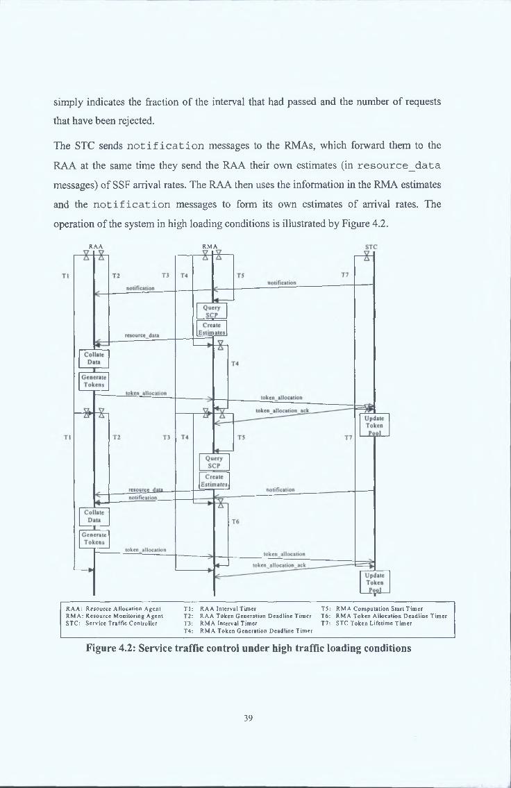
The STC sends n o t i f i c a t i o n messages to the RMAs, which forward them to the
RAA at the same time they send the RAA their own estimates (in r e s o u r c e _ d a t a
messages) of SSF arrival rates. The RAA then uses the information in the RMA estimates
and the n o t i f i c a t i o n messages to form its own estimates o f arrival rates. The
operation o f the system in high loading conditions is illustrated by Figure 4.2.
RAA RM A
R A A : R esource A Uocation A gen l T l : RA A Interval T im er T5: RM A C om putation S tart T im erR M A : R esource M onitoring A gent T2: RA A Token G eneration D eadline T im er T6: RM A Token A llocation D ead line T im erSTC : S erv ice T raffic C ontro ller T3: RM A Interval T im er T7: STC Token Lifetim e T im er
T4: RM A Token G eneration D eadline T im er
Figure 4.2: Service traffic control under high traffic loading conditions
39

The degree o f effectiveness o f the token-based control is to an extent dependant on two
temporal constraints: firstly r e s o u r c e _ d a t a messages from the RMA should arrive at
the RAA before the token generation deadline; secondly at least one
t o k e n _ a l l o c a t i o n message should be received at the STC before the start o f the
next interval. To allow the system dynamically adjust its operational parameters so that
both o f these timing constraints are met two error messages are introduced:
l a te _ _ d a ta _ w a r n in g and l a t e _ a l l o c _ w a r n i n g .
The operation o f the system in response to the reception o f a l a t e _ d a t a _ w a r n i n g
message is illustrated by Figure 4.3. By keeping the length o f Timer T5 as long as
possible the RMA attempts to get an as up-to-date an estimate as possible of the load of
its associated SCF resources. However if T5 is too long the r e s o u r c e _ d a t a message
sent to the RAA will arrive late and no tokens will be allocated for the SCF for the
coming interval. Upon reception o f a late r e s o u r c e _ d a t a the RAA sends the
originating RMA a l a t e _ d a t a _ w a r n i n g message, which causes the RMA to reduce
the length o f subsequent T5 timers. The l a t e _ d a t a _ w a r n i n g indicates the amount o f
time after the token generation deadline that the r e s o u r c e _ d a t a arrived; this value is
used in the calculation o f the amount by which T5 should be reduced. It is noted that if
the RAA sets the token generation deadline conservatively, it may still be able to take
account o f a ‘late’ r e s o u r c e _ d a t a message (arriving sometime within some preset
time after T2 expiry) and subsequently send a t o k e n _ a l l o c a t i o n to the RMA in
question. After a pre-specified number o f intervals the RMA may increase T5, however
this should not be done if the RMA has received n o t i f i c a t i o n messages during
those intervals.
The operation o f the system in response to the reception o f a l a t e r a l l o c _ w a r n i n g
message is illustrated by Figure 4.4. The RAA uses timer T2 to ensure the token
generation process starts in sufficient time to allow the propagation o f
t o k e n _ a l l o c a t i o n messages to all STCs in advance o f the start o f the next interval.
Whilst meeting this constraint is its priority the RAA also attempts to keep T2 as long as
4.2.4 Dynamic Timing
40

possible so that the information received from RMA/STCs and used as input to the token
generation process is as up-to-date as possible.
RAA RM A STC
Figure 4.3: Response of system to l a t e d a ta w arning message
41

R A A RM A S T C
Figure 4.4: Response of system to l a t e a l l o c w arning message
As indicated previously the RMA attempts to forward t o k e n _ a l l o c a t i o n messages
so that they reach their destination STC in time for the next interval. If the RMA receives
the t o k e n _ a l l o c a t i o n from the RAA too late to make this possible, it sends a
l a t e _ a l l o c _ w a r n i n g to the RAA, indicating the time interval by which the
42

received t o k e n _ a l l o c a t i o n was late. On receiving this message, the RAA decreases
the token generation deadline by an amount calculated using the lateness interval
indicated in the l a t e _ a l l o c _ w a r n i n g . In the event that the RAA receives a
l a t e _ a l l o c _ w a r n i n g requiring the token generation deadline to be less than a pre
specified fraction, Deadline Limit, o f the interval length, the interval length is increased
instead. The token generation deadline is communicated to the RMAs in
t o k e n _ a l l o c a t i o n messages, therefore the newly calculated deadline cannot be
used for the current interval; as illustrated in Figure 4.4, it comes into effect for the next
interval.
4.3 I m p l e m e n t a t io n
This section provides a description o f the implementation o f the MARINER Service
Traffic Load Control System. Figure 4.3 illustrates the structure o f the o f the MARINER
System implementation.
Figure 4.3 - MARINER System Implementation
43

The Resource Monitoring Agents (RMA) and the Resource Allocation Agents (RAA)
were implemented on the IKV++ Grasshopper Intelligent Agent System. The Service
Traffic Controller (STC) was implemented as part o f the SSF in the IN Model described
in Chapter 3. The rest o f this section describes the Grasshopper System and the three
entities.
4.3.1 The Grasshopper Intelligent Agent System
Grasshopper™ [GRASSHOPPER] is a mobile agent development and runtime platform
that is built on top of a distributed processing environment. It is implemented in Java,
and is designed conformant to the Object Management Group’s Mobile Agent System
Interoperability Facility (MASIF)[MASIF].
The implementation for the MARINER System includes Grasshopper FIPA extensions
that includes the following agents:
■ the Agent Communication Channel (ACC), which facilitates agent communication
■ the Directory Facilitator (DF), which allows agent to locate each other
■ the Agent Management Service (AMS), which manages the agent start-up and
maintains a list o f live agents.
4.3.2 Service Traffic Controller
The STC, residing within the SSF, controls the acceptance o f new service session
requests at the SSF through the use of token allocations received from an RAA. It:
• accepts t o k e n _ a l l o c a t i o n messages from RMAs and uses the intervallD
parameter contained therein to decide whether to update its data. If an update is to be
done it extracts and stores token allocations for the next interval and the length o f that
interval;
• at the expiry of current interval timer (T7), it updates the token pool and starts a new
interval timer using the new token allocations and interval length contained in the
t o k e n _ a l l o c a t i o n ( s ) ;
44
• on receipt o f a t o k e n _ a l l o c a t i o n message, it optionally calculates token usage
thresholds per service that once surpassed will trigger the sending o f a
n o t i f i c a t i o n message during the next interval. This calculation is based on
token allocations and pre-specified threshold percentages for each service;
• receives requests for permission to accept a new service session from the SSF. It
checks the corresponding token pool. If the session is to be accepted, it indicates this
and the destination SCF address to the SSF and subtracts a single token from the
corresponding token pool. If the session is to be rejected it indicates this to the SSF;
• sends a n o t i f i c a t i o n to RMAs when the number o f tokens remaining for a
particular service falls below the pre-calculated service threshold. This
n o t i f i c a t i o n indicates the service type and the fraction o f the interval that has
passed up to the time when the n o t i f i c a t i o n is generated;
• optionally sends one or more n o t i f i c a t i o n to RMAs when it has exhausted its
tokens for a particular service (or set of services). These n o t i f i c a t i o n messages
can be sent immediately upon token exhaustion and/or at subsequent time intervals.
In the latter case the n o t i f i c a t i o n will indicate the number o f service session
requests that have been rejected since token exhaustion;
• optionally re-uses the last t o k e n _ a l l o c a t i o n message it received if a new one
has not been received at the expiry o f current interval timer (T7).
A more detailed description o f the implementation o f this function with the SSF is
available in Appendix B.
4.3.3 Resource Monitoring Agent
The Resource Monitoring Agent is associated with one or more network resource types.
In the case o f the SCF, it monitors the SCF resources’ available processing capacity,
estimates session arrival rates on a per service per SSF basis and reports this information
to the RAA. It:
• sends and receives messages to and from the RAA and STCs;
45
• upon expiry o f timer T5 accesses data relating to current service request arrivals rates
by service and SSF at the SCF. Also accesses data that relates to the SCF resources’
available processing capacity and the processing cost for sessions o f the service types
supported by that SCF. Places this information in a r e s o u r c e _ d a t a message and
sends this to the RAA;
• receives t o k e n _ a l l o c a t i o n messages from the RAA and extracts information
regarding the interval length and token generation deadline. Uses this information to
calculate the duration o f timers T4, T5 and T6;
• forwards t o k e n _ a l l o c a t i o n messages to STCs;
• upon receipt o f a l a t e _ d a t a _ w a r n i n g , decreases the length o f timer T3 by an
amount calculated using the information on the latency o f the bid contained in the
l a t e _ d a t a _ w a r n i n g ;
• keeps measurements o f the latency between itself and STCs and uses this information
to ensure that the STC receives the t o k e n _ a l l o c a t i o n messages as close to the
beginning o f the new interval as possible;
• sends a l a t e _ a l l o c _ w a r n i n g to the RAA if t o k e n _ a l l o c a t i o n is received
after the expiry of timer T6.
A more detailed description o f the implementation classes o f this function is available in
Appendix C.
4.3.4 Resource AIlocation Agent
The RAA controls network resource loads in a co-ordinated manner through receiving
data from RMAs and STCs, the running o f the token generation process and the
propagation o f token allocation to STCs. It:
• upon expiry o f timer T2 (or at some preset time thereafter) collates data received in
r e s o u r c e _ d a t a messages from the RMAs to form estimates o f service arrival
rates on a per service per SSF basis. If n o t i f i c a t i o n messages have been
46

received then the information contained therein is also used in the formation of
service arrival rate estimates;
• sends l a t e _ d a t a _ w a r n i n g messages to RMAs whose r e s o u r c e _ d a t a
messages arrived after the expiry o f T2. The l a t e _ d a t a _ w a r n i n g indicates the
degree o f latency of the r e s o u r c e _ d a t a message;
• runs the token generation process to generate token allocations on a per SCF, per
SSF, per service type basis;
• sends t o k e n _ a l l o c a t i o n messages containing the token allocations, the duration
o f the next interval, and the token generation deadline, to all RMAs;
• shortens T2 if a l a t e _ a l l o c _ w a r n i n g message is received. The new token
generation deadline will only be sent out with the next t o k e n _ a l l o c a t i o n and
therefore only be enforced in the following interval;
• increases the interval length if the newly calculated token generation deadline
corresponds to less than the Deadline Limit o f the current interval length.
A more detailed description of the implementation classes o f this function is available in
Appendix C.
4.4 Su m m a r y
With the exponential growth of the telecommunication service traffic spurred by
changing regulations and the convergence o f the internet, mobile telephony and landed
networks, current load control mechanisms for Intelligent Networks are seen as
inadequate in that they are reactive, node-orientated, static and operate at the messaging
level.
Network orientated load control mechanisms provide a solution to these inadequacies in
that they are inherently network-orientated, proactive, dynamic and operate at the
service-level. The MARINER Service Traffic Load Control System attempts to provide
the IN with a network orientated load control mechanism that is better prepared to handle
the challenges on the horizon. This is accomplished through the following steps:
47

• Resource Monitoring Agents monitor the current loads of the IN resources (such as
the SCF processing capacity) and service traffic arrival rates. This data is
periodically reported to the Resource Allocation Agent.
• The Resource Allocation Agent uses this data to assess the various IN resources’
availability and traffic arrival rates at the SSFs. Using these assessments, it
periodically allocates resource usage to the SSFs using the Service Traffic Controllers
built into them according to the service type priority level (profit) set by the operator.
• The Service Traffic Controllers distribute incoming service traffic to the IN resources
according to the resource usage information it received from the Resource Allocation
Agent. I f it exhausts the resource usage allocated to it for a particular service type
before the next allocation arrives, the Service Traffic Controller begins to reject
service requests o f that type and notifies the Resource Allocation Agent of this.
• If the Resource Allocation Agent receives notifications from the Service Traffic
Controllers, it processes them, discerns the nature (service type, extent and location)
o f the impending overload, and reassigns resources to maximise network-utilisation
and operator-profit from the overload while protecting individual nodes from
overloading.
This candidate was responsible for the design and development o f the Service Traffic
Controller and significantly contributed to the development o f the Resource Allocation
Agent and the Resource Monitoring Agent. This endeavour however, would have been
impossible without the contributions, guidance and advice o f the rest o f the MARINER
Project participants, especially the TELTEC IN Group and IKV for the Grasshopper
FIPA Platform.
The next chapter uses experimental data to verify the operation and performance o f the
MARINER System.
48
5 EXPERIMENTS AND RESULTS
5.1 I n t r o d u c t io n
This chapter details the experiments that were carried out on the MARINER Service
Traffic Load Control System as part o f the effort to demonstrate and analyse the
performance o f this system as a network orientated load control mechanism for the
Intelligent Network. These experiments explore the following characteristics of the
MARINER System:
• adaptive load control - its ability to integrate with the IN, and adapt its load control
parameters to the network and traffic conditions
• network-orientation - the ability to balance load among the available nodes,
maximising network utilisation while protecting individual nodes from overloads
• service-orientation - the ability to differentiate between service types, and maximise
service profit (§ 4.2.1) as set by the operator.
• proactive - its ability to distribute and control a spontaneous traffic overload.
• robustivity - the ability o f the system to recover from node or agent malfunctions and
lost or corrupted communication
• the limitations o f the system
The experiments were structured into three phases, with each phase feeding its results
into the next phase, while further testing the conclusions drawn from the previous phase.
The first phase comprised the integration experiments. These experiments verified that
the Trial Platform operated according to the MARINER System as described in Chapter
4, hence confirming that all subsequent experiments performed on the Trial Platform
were indeed testing the MARINER System. Further, the experiments were also used to
test that the MARINER System integrated successfully with the IN Model described in
Chapter 3. This was followed by the evaluation experiments. These experiments tested
the performance o f the MARINER System against the criteria set out in § 5.1.1. Finally,
49

the robustness experiments were carried out. These tested the robustness of the
MARINER System in various error conditions and explored its limitations. In describing
the above process, this chapter is structured in the following manner. First, the
experimental setup is described. This is followed by sections on the experiments and
results from each phase o f the experiment process. Finally, the results of the experiments
are summarised and analysed. Further descriptions o f these trials are available in
[MARINERD8] ['Wathan2000].
5.1.1 Evaluation Criteria
The Evaluation Experiments that were carried out analysed the performance and
behaviour of the MARINER System against the following criteria.
• Overload Protection
The load control system must control the network load to match the offered load in
all circumstance except when the offered load exceeds the safe maximum of 90%
of the capacity o f the network. In the case when the offered load exceeds the safe
maximum, the load control system must maintain the network load at the safe
maximum. In the case when the offered load increases or decreases rapidly, the
load control system must ensure that the accepted load matches the offered load as
closely as possible without exposing the network to an offered load above the safe
maximum.
• Load Distribution
The load control system must ensure the equal distribution o f the offered load
among all nodes within the controlled network. In the case where the offered load
comprises multiple service types, the load control system must ensure the equal
distribution o f the offered load o f each service type among all nodes capable o f
executing that service type.
• Service Differentiation
The load control system must always ensure that the network capacity is utilised
such that the network profit is maximised. Specifically, in the case where the
50

offered load exceeds the safe maximum capacity of the network, the load control
system must distinguish between the service types that make up the offered load
and ensure that the service requests are rejected according to their profit value to
the network, the least profitable being the first to be rejected.
These criteria were chosen due the fact that they were considered by this candidate to
accurately measure the effectiveness and practical value o f any load control system. This
consideration is supported in [Arvidsson99] where it is stated that they accurately
represent the viewpoints o f the network operator, network users, and the network itself.
These criteria have also been used to evaluate other network management systems
including the Global IN Congestion Control Strategy [Lodge2000], and Automatic Call
Restriction [Williams94], as well as in the discussions presented in [Arvidsson97],
[Pettersson96], [Williams2002], [Hnatyshin2001], [Dovrolis2000] and [Mohapi2000].
Other popular criteria used for the evaluation o f load control systems are Service Fairness
[Lodge2000], [Folkestad96], Source Fairness [Whetten2000][P8132000] and
Minimisation o f User Delay [Kant95][Williams2002]. These criteria were deemed
unsuitable for use in the evaluation of the MARINER System for the following reasons.
• Service Fairness
Service Fairness is defined by [Rumsewicz96], [Galletti92] and [Tsolas92] as a
strategy where, in response to an overload, the load control system should reject
only the service type that is causing the overload. This criterion was not chosen
because it ignores the fact that most current networks are governed by multiple
Service Level Agreements ensuring that services types are distinguished and treated
based on their importance and urgency to both the network provider and the
network user. In the event o f an overload, it is therefore more important that the
network attempts to service the most number o f requests o f the most important
service rather than reject service requests based on the service type causing the
overload.
• Source Fairness
51

Source Fairness is defined by [Hac98] as a criterion where, in response to an
overload, the load control system should ensure that it only rejects load from the
sources (SSPs) causing the overload. This criterion was not chosen because it too
does not distinguish between Service Types and their importance to the Network
Operator and Users.
• Bound User Delay
Bound User Delay is defined by [Kant95] as a requirement for the load control
system to ensure that the average length of time each user must wait for service
implementation to be completed should not be exceed a Maximum User Delay
during an overload. This criterion was not chosen due to the fact that it was
considered to be pertinent only for load control systems operating at the service-
messaging levels, which could lead to service completion times varying by large
amounts during an overload. Since the load control system being evaluated in this
paper operates at the service level, once a service request is accepted, the resources
it requires (represented by tokens in the SSP) are committed, ensuring no large
discrepancies between service completion times during an overload.
5.2 E x p e r im e n t a l Setu p
5.2.1 Trial P la tform
The Trial Platform consists of a CORBA-based IN Model described in Chapter 3, the
Grasshopper Platform and the MARINER System described in Chapter 4.
52

Figure 5.1 - The Trial Platform
The IN Model served to model a distributed IN environment containing SCPs, SSPs and
Traffic Generators. The SSPs were equipped with Service Traffic Controllers (STCs) as
described in § 4.3.2. The STCs were set to send Notifications only when tokens for a
particular service type were exhausted, and to re-use the last token__allocation if a new
one did not arrive in time. The design also included the integration o f load control
agents, while providing maximum de-coupling between the operations o f the IN Model
and the agents. Hence, making it possible to introduce new versions o f agents and load
control strategies without necessitating modifications to the model.
For the purposes of the trial, the model is able to execute three different services. The
design of the model however allows for the inclusion of further service with only minor
modifications. The three services are as described below.
5.2.1.1 Service 0: Restricted User
This service was implemented as described in § 2.4.1 (See Appendix B). The total
numbers o f instructions carried out at each network element are as follows:
SSP: 135,000 instructions[RBi]
53

The profit associated with a successful session of the Restricted Access Call Forward
service is 1 profit unit.
5.2.1.2 Service 1: Virtual Private Network
The service was implemented as described in § 2.4.2 (See Appendix B). The total
number o f instructions carried out at each network element is as follows:
SSP: 97,500 instructions
SCP: 240,000 instructions[RB2]
The profit associated with a successful session of the VPN service is 5 profit units.
5.2.1.3 Service 2: Automatic Ringback
The service was implemented as described in § 2.4.3 (See Appendix B). The total
numbers o f instructions carried out at each network element are as follows:
SSP: 242,500 instructions[RB3]
SCP: 300,000 instructions
The profit associated with a successful session o f the Ringback service is 10 profit units
5.2.2 Standard Trial Configuration and Assumptions
The standard configuration for the experiments were as follows:
■ An IN network comprising of 6 SSPs and 2 SCPs running on a single system.
■ Traffic Generators generating service requests o f all three types to the IN network at
an equal rate.
■ 2 RMAs and one RAA operating on the Grasshopper Platform running on a single
system.
It should be noted that in order to obtain meaningful results, both the load offered to the
network and the load processed by the SCFs are measured as percentages o f the total
SCP: 160,000 instructions
54

processing capacity of all the SCFs in the network. Therefore, in the case where 100%
load is offered to the network, all the SCFs in the network would have to be working at
full capacity in order to service all the requests being generated by the Traffic Generator.
Further, auction intervals are used as a measure o f the passage o f time in the experiments,
where on auction interval is the fixed interval in milliseconds between to auction
processes within the Distributor Agent.
The following assumptions are used in all experiments:
■ Service users never abandon ongoing service sessions, thus it is not necessary to
implement the signalling required for premature session termination.
■ Processing requirements remain constant for a particular signal over all sessions o f
that service type.
■ All network links are identical and provided by 10MB Ethernet.
■ All SCFs have identical hardware and software configurations and support all
services.
■ The targeted safe maximum load for an SCF is 90% [Sabourin91].
■ All [NW4]Traffic Generators originate requests for services according to independent
Poisson processes.
■ Any delay at SSFs is related to processing only.
■ For all scenarios, the mean arrival rates for all services are equal unless stated
otherwise.
5.3 I n t e g r a t io n E x p e r im e n t s
The integration experiments investigated all aspects o f the Trial Platform in order to
verify that it operated in accordance with the MARINER System, as described in § 4.2.
This was done to verify that all subsequent experiments carried out on the Trial Platform
did indeed test the performance o f the MARINER System. These experiments were
carried out during the development period of the system so that the results could be fed-
back into the development process and used to improve the system.
55

5.3.1.1 Basic Platform Setup
Objective(s) o f experiment: To verify that the MARINER Agent System interacts with
the IN Model such that the platform operates as described
in § 4.2.1
Experimental setup: Standard Configuration
Experimental procedure: Configure a standard IN network and deploy the
Grasshopper agents on it. Turn on traffic generation at 35%
steady load and verify that token allocations are taking
place and that load is being distributed.
5.3.1.2 Agent Dynamic Timing
Objective(s) o f experiment: To verify that MARINER Agents dynamically adjust their
timing values to adapt to the environment as described in §
4.2.3.
Experimental setup: Standard Configuration.
Experimental procedure: Proceed as in experiment 1 with the interval set at 60
seconds and the RMA and RAA timers set at an initial
value o f 35s. Under a 35% steady load verify that token
allocations are taking place and monitor the timing values
of the MARINER Agents.
5.3.2 Integration Results
5.3.2.1 Experiment 1: Basic Platform Setup
Through the duration o f this experiment, the IN Model successfully generated and
executed services while the MARINER Agents monitored and controlled the network
load through the implementation o f the market-based strategy in the manner described in
§4.2
56

Further to achieving its objectives, this experiment allowed for the fine-tuning o f the
configuration parameters o f both the IN Model and MARINER System, hence assuring
consistency throughout the remainder o f the trial.
5.3.2.2 Experiment 2: Agent Dynamic Timing
This experiment tests the ability o f the RMA and RAAs to dynamically adapt their
operation times to the network environment. The results of the experiment should show
the RMA Computation Start Period (T5 in Figure 4.3) increase at the beginning until it
reaches the point where the RMA is accessing the SCP at the very latest it can without
missing the token generation deadline. At this stage, the RMA Computation Start Period
will fluctuate about this point as the RMA attempts to increase it further and the RAA
sends late_data_wamings, forcing the RMA to decrease it. This fluctuation allows the
RMA to rapidly adjust to a change in the network.
In the RAA, the results should show the RAA increasing the Token Generation Deadline
Period (T2 in Figure 4.4) until it reaches a point where the Token Generation Procedure
occurs as late as it can, while ascertaining that the token_allocation reaches the STC at
the beginning o f the next Interval. At this stage, the Token Generation Deadline Period
should fluctuate about this point as the RAA attempts to increase it further and the RMA
sends late_allocation_warnings, forcing the RAA to decrease it. This fluctuation allows
the RAA to rapidly adjust to a change in the network.

RMA Timing
N » t- P» « NN n n (1 n n
I n te r v a l
^ ^ ^ m E S S
RMA Computation Start Period |
Figure 5.2 - RMA Dynamic Timing
The graph shows that the RMA Computation Start Timer is working as expected. From
its initial value o f 35s, it gradually increases with every interval to the 47s. At this point,
the RAA sends a late_data_warning to the RMA causing it to reduce the Timer period
to 43s. It then attempts to increase the period in the subsequent intervals until a warning
is received. This cycle repeats itself for the duration of the experiment.
RAA Timing
§ 50
il1«
*- n in
Auction Interval RAA Token Generation Period
Figure 5.3 - RAA Dynamic Timing
The graph shows that the RAA Token Generation Timer is working as expected. From
its initial value o f 35s, it gradually increases with every interval to the about 52s. At this
58
point, the RMA sends a late_allocation_warning to the RAA causing it to reduce the
Timer period to about 45s. It then attempts to increase the period in the subsequent
intervals until a warning is received. This cycle repeats itself for the duration o f the
experiment. The interval length stays at 60s.
The results o f this section have shown that Trial Platform does work as described in §
4.2, in accordance to the MARINER System. This finding allows all subsequent
experiments on the Trial Platform to test and demonstrate the performance o f the
MARINER System.
5.4 E v a l u a t io n E x p e r im e n t s
The Evaluation experiments tested the load control and overload protection aspects o f the
Trial Platform and hence, the MARINER System.
5.4.1.1 Normal Load Under Steady State
Objective(s) o f experiment: To verify that the system operates as required under a
steady state load.
Experimental setup: Standard Configuration
Experimental procedure: Configure a standard IN network and deploy the
MARINER agents on it. Start traffic generation at the
normal steady state rate o f 35% and capture load
information for the network. By analysis of the loading data
verify that the MARINER agents are operating correctly.
5.4.1.2 Excessive Load Under Steady State
Objective(s) o f experiment: To verify the operation o f MARINER agents under
excessive steady state load.
Experimental setup: Standard Configuration with traffic generator set for arrival
rates amounting to:
2.1 95% Load
59

Experimental procedure: Configure a standard IN network and deploy the
MARINER agents on it. Start traffic generation with
services 0 and 2 having a normal (as in Experiment 1)
arrival rate and service 1 having an elevated arrival rate so
that the total traffic generated is as described in he
experimental setup. Capture load information for the
network. By analysis of the loading data verify that the
MARINER agents are operating correctly.
5.4.1.3 Excessive Load for Limited Periods
Objective(s) o f experiment: To verify the operation of MARINER agents under
excessive load for limited periods.
Experimental setup: In this case, the network load is modified by having a
higher arrival rate for Service 1 that only last for a short
period as follows. First the network is exposed to normal
load for 30 intervals, then to an overload for 10 intervals,
simulating a spontaneous high traffic period. This is
followed by an exposure to 75% of the overload for 10
intervals, simulating rejected customers re-dialling. Finally,
the network is exposed to a normal load. The extent of the
overload is as follows:
3.1 95% Load
3.2 120% Load
Experimental procedure: Configure a standard IN network and deploy the
MARINER agents on it. Start traffic generation as
described in experimental setup and capture load
information for the network. By analysis of the loading data
verify that the MARINER agents are operating correctly.
2.2 120% Load
60

Objective(s) o f experiment: To verify the operation of MARINER agents under
excessive localised load for limited periods.
Experimental setup: In this case use normal load for all nodes except one SSP.
At this SSP generate excessive traffic of 120% Load for 10
intervals followed by excessive traffic of 75% of 120%
load for 10 intervals. Then, resume normal loading.
Experimental procedure: Configure a standard IN network and deploy the
MARINER agents on it. Start traffic generation as
described in experimental setup and capture load
information for the network. By analysis of the loading data
verify that the MARINER agents are operating correctly.
5.4.2 Evaluation Results
In this section, the theoretical result of each of the evaluation experiments is first
presented. This is followed by the observed result, presented in graphic form. At the end
of each experiment, the obtained results are analysed.
The presented graphs are as follows:
■ The first graph shows the individual and average SCP loads as a percentage of their
full processing capacity across the duration of the experiment. This graph serves to
explore the degree of success achieved by the Mariner System in balancing the load
across the network, and protecting the network in an overload.
■ The next graph shows the difference between the load arriving into the network and
the load accepted for execution. It serves to illustrate the sensitivity of the Mariner
System.
■ The third graph displays the breakdown of the services being executed by the
network. The degree of success achieved in evenly balancing the services accepted in
normal loads and the preferential treatment of the more profitable services in
5.4.1.4 Localised Excessive Load For Limited Periods
61

overloads is illustrated in this graph. The graph also illustrates an estimate of the
traffic load being offered to the IN model.
5.4.2.1 Experiment 1: Normal Load Under Steady State
In this experiment, the network load should remain at 35%, matching the offered load as
closely as possible. All SCPs should receive an equal distribution of the accepted load,
and hence should closely match the average SCP load. Further, with the network load
well below the safe network maximum of 90%, all three services should be treated
equally, with no service requests being rejected by the IN network.
Load Balancing
Auction Interval
p Scf200 load Scf201 load----------Average SCP Load |
Figure 5.4 - Load Balancing at Normal Load
The graph shows that under a steady load of 35%, the SSPs distribute load evenly
between the available SCPs .
62

Offered Load - Accepted Load
Auction Interval
Figure 5.5 - Load Difference at Normal Load
This graph shows that less than 1% of the offered load was ever rejected by the SSPs
when the system was under a steady load of 35%.
Accepted Load by Service
|— Average SO Load CZZ) Average S1 Load IZ^J Average S2 Load — Estimated Offered Load j
Figure 5.6 - Service Balancing at Normal Load
63

Figure 5.6 confirms that under normal steady state conditions, the network treated the
three services equally, with an insignificant number of service rejections.
The results above verify that the MARINER System successfully controls and distributes
the offered load when the traffic is at a steady normal level.
5.4.2.2 Experiment 2.1: 95% Excessive Load Under Steady State
In this experiment, the MARINER agents should maintain the network load at the safe
maximum of 90%, quenching only 5% of the offered load. Further, the requests for the
less profitable services should the ones most quenched.
Load Balancing
| Scf200 load Scf201 load — -Average SCP Load]
Figure 5.7 - Load Balancing at 95% Load
The graph shows that under a steady load of 95%, the SSPs distribute load evenly
between the available SCPs .
64

Offered Load - Accepted Load
Auction Interval
Figure 5.8 - Load Difference at 95% Load
This graph shows that approximately 20% of the offered load was rejected when the
system was offered a steady load of 95%.
Accepted Load by Service
Auction Interval
| Average SO Load tZZ3Average S1 Load IZZ3 Average S2 Load — Estimated Offered Load |
Figure 5.9 - Service Balancing at 95% Load
65

Figure 5.9 shows that under an excessive load of 95%, the network rejected the service
with the lowest profit value (Service 0) and accepted all requests of the service with the
highest profit value (Service 3).
The results above verify that the MARINER System successfully maximises profit and
distributes the offered load when the traffic is at a steady excessive level just above the
90% SCP safe limit. However, they also show that at this level, the accepted load is
over-controlled such that 15% of the offered load was unnecessarily discarded. The
reason behind this is that at a level so close to the safe limit, the inaccuracy of the single
notification option set in the experimental setup (§ 5.2.2) is magnified. Setting the STC
to send multiple notifications would solve this problem.
5.4.2.3 Experiment 2.2: 120% Excessive Load Under Steady State
In this experiment, the MARINER agents should maintain the network load at the safe
maximum of 90%, quenching 30% of the offered load. Further, the requests for the less
profitable services should the ones most quenched.
Load Balancing
F Scf200 load............Scf20l load---------- Average SCP Load |
Figure 5.10 - Load Balancing at 120% Load
The graph shows that under a steady load of 120%, the SSPs distribute load evenly
between the available SCPs.
66
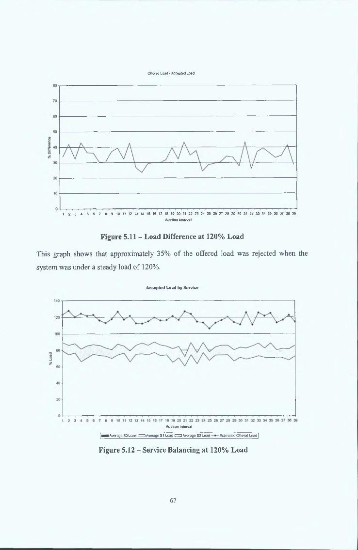
Offered Lead - Accepted Load
1 2 3 4 5 6 7 8 9 10 11 12 13 14 15 16 17 18 19 20 21 22 23 24 25 26 27 28 29 30 31 32 33 34 35 36 37 38 39
Auction Interval
Figure 5.11 - Load Difference at 120% Load
This graph shows that approximately 35% of the offered load was rejected when the
system was under a steady load of 120%.
Accepted Load by Service
Auction Interval
[¡^■Average SO Load CZZ3Average S1 Load c m Average S2 Load Estimated Offered Load |
Figure 5.12 - Service Balancing at 120% Load
67
Figure 5.12 shows that under an excessive load of 120%, the network rejected the service
with the lowest profit value (Service 0) and accepted all requests of the service with the
highest profit value (Service 3).
The results above verify that the MARINER System successfully maximises profit and
distributes the offered load when the traffic an excessive level. It is also observed that a
slight amount of over-controlling is still manifested by the system with approximately 5%
of the load being unnecessarily discarded. As in experiment 2.1, this is a result of using
the single notification option in the STC. It should be noted that the degree over
controlling is drastically reduced with higher overloads. A more accurate result could be
achieved using the multiple notification option.
5A2A Experiment 3.1: Excessive Load of 95% for 20 Intervals
In this experiment, the MARINER agents should maintain the network load at 35% until
the arrival of the spike. Then, the network load should increase with the offered load
until reaching the 90% safe maximum, and be maintained at that level for the duration of
the spike. At this stage, 5% of the arriving service requests should be quenched, with the
less profitable services having the most number quenched. When the spike falls to 75%
of its value, the network load should fall with it, and accept all service requests. At the
end of the spike, the network load should fall back to 35%, and all service requests
should be serviced.
68

Load Balancing
Auction Interval
| Scf200 load Scf201 load--------Average SCP Load]
Figure 5.13 - Load Balancing at 95% Spike
The graph shows the network load was distributed evenly between the available SCPs
throughout the experiment.
Offered Load - Accepted Load
Auction Interval
Figure 5.14 - Load Difference at 95% Spike
The figure above illustrates that the network accepted nearly all the offered load in the
periods before and after the traffic spike. In the first phase of the spike, when the offered
69

load was at the 95% level, the network initially rejects about 30% of the offered load, but
gradually settles to about 15%. In the second phase of the spike, the network eventually
settles to rejecting about 3% of the offered load.
Accepted Load by Service
120 ----------------------
3_i
Auction Interval
[^■ A verage SO Load CZJAverage S1 Load CUAverage S2 Load —»—Estimated Offered Load |
Figure 5.15 - Service Balancing at 95% Spike
The figure shows that all service requests were accepted in the periods before and after
the spike. In the first phase of the spike, the system gradually rejected all of the least
profitable service requests (Service 0) and none of the most profitable service requests
(Service 2). In the second phase of the spike, the system rejected only a small proportion
of the Service 0 requests.
The results of this experiment show that the MARINER System is successfully able to
adapt to spontaneous multi-phased sharp increases in traffic. The individual graphs show
that the offered load was successfully controlled and distributed, while the network was
protected against the sudden overload.
A point of note is that the network has a tendency to over-control the accepted load on
the on-set of a spike, but quickly adapts to the optimum level. This effect is a result of
the MARINER System attempting to ensure protection against an overload whilst the
traffic level is rising.
70

In this experiment, the MARINER agents should maintain the network load at 35% until
the arrival of the spike. Then, the network load should increase with the offered load
until reaching the 90% safe maximum, and be maintained at that level for the duration of
the spike. At this stage, 30% of the arriving service requests should be quenched, with
the less profitable services having the most number quenched. When the spike falls to
75% of its value, the network load should fall with it, and accept all service requests. At
the end of the spike, the network load should fall back to 35%, and all service requests
should be serviced.
5.4.2.5 Experiment 3.2: Excessive Load of 120% for 20 Intervals
Load Balancing
Auction Interval
F Scf200 load........... Scf201 load Average SCP Load |
Figure 5.16 - Load Balancing at 120% Spike
The graph shows the network load was distributed evenly between the available SCPs
throughout the experiment.
71

Offered Load - Accepted Load
Auction Interval
Figure 5.17 - Load Difference at 120% Spike
The figure above illustrates that the network accepted nearly all the offered load in the
periods before and after the traffic spike. In the first phase of the spike, when the offered
load was at the 120% level, the network initially rejects about 47% of the offered load,
but gradually settles to about 30%. In the second phase of the spike, the network
eventually settles to rejecting about 10% of the offered load.
72

Offered Load by Service
CM «M W «
Auction Interval
| A v e r a g e SO Load □ Average S1 Load CZZ3Average S2 Load —»—Estimated Offered Load |
Figure 5.18 - Service Balancing at 120% Spike
The figure shows that all service requests were accepted in the periods before and after
the spike. In the first phase of the spike, the system gradually rejected all of the least
profitable service requests (Service 0) and none of the most profitable service requests
(Service 2). In the second phase of the spike, some of the Service 0 requests were
accepted.
The results of this experiment show that the MARINER System is successfully able to
adapt to spontaneous multi-phased sharp increases in traffic to an extreme level. The
individual graphs show that the offered load was successfully controlled and distributed,
while the network was protected against the sudden overload.
A point of note is that the network has a tendency to over-control the accepted load on
the on-set of a spike, but quickly adapts to the optimum level. This effect is a result of
the MARINER Architecture attempting to ensure protection against an overload whilst
the traffic level is rising.
5.4.2.6 Experiment 4: 120% Localised Excessive Load for 20 Intervals
Although the spike only occurs at a single SSP, the MARINER Agents should have a
similar response towards the network as in the event of the global spikes in Experiment 3.
73

Load Balancing
Auction Interval
| Scf200 load Scf201 load Average SCP Load |
Figure 5.19 - Load Balancing at Localised 120% Spike
The graph shows the network load was distributed evenly between the available SCPs
throughout the experiment.
Offered Load - Accepted Load
•» m mAuction Interval
Figure 5.20 - Load Difference at Localised 120% Spike
The figure above illustrates that the network accepted nearly all the offered load in the
periods before and after the traffic spike. In the first phase of the spike, when the offered
load was at the 95% level, the network initially rejects about 60% of the offered load, but
74

gradually settles to about 35%. In the second phase of the spike, the network eventually
settles to rejecting about 20% of the offered load.
Offered Load by Service
140 ------------------------------------------------------------------------------------------------------------------------------------------------------------------------------------------ -----------
Figure 5.21 - Service Balancing at at Localised 120% Spike
The figure shows that all service requests were accepted in the periods before and after
the spike. In the first phase of the spike, the system gradually rejected all of the least
profitable service requests (Service 0) and none of the most profitable service requests
(Service 2). In the second phase of the spike, the system rejected only a small proportion
of the Service 0 requests.
The results of this experiment show that the MARINER System is successfully able to
adapt to local spontaneous multi-phased sharp increases in traffic. The individual graphs
show that the offered load was successfully controlled and distributed, while the network
was protected against the sudden overload.
A point of note is that the network has a tendency to over-control the accepted load on
the on-set of a spike, but quickly adapts to the optimum level. This effect is a result of
the MARINER System attempting to ensure protection against an overload whilst the
traffic level is rising.
75

The robustness experiments were designed to exhaustively examine the robustness and
limitations of the Trial Platform and hence the MARINER System. The experiments
were categorised into three error conditions, namely
■ the malfunctioning of platform components
■ the increase in network delays
■ the loss of communication messages
5.5.1.1 RMA Malfunction
Objective(s) o f experiment: To verify that the system operates correctly when the RMA
malfunctions.
Experimental setup Standard Configuration
Experimental procedure: Configure a standard IN network and deploy the
MARINER agents on it. Start traffic generation at an
excessive steady state rate of 95% and capture load
information for the network. Force a RMA shutdown and
monitor the IN Platform. By analysis of the loading data
verify that the MARINER agents are operating correctly.
5.5.1.2 RAA Malfunction
Objective(s) o f experiment: To verify that the IN System operates correctly when the
RAA malfunctions.
Experimental setup: Standard Configuration
Experimental procedure: Configure a standard IN network and deploy the
MARINER agents on it. Start traffic generation at the
normal steady state rate of 35% and capture load
information for the network. After 15 intervals, force a
RAA shutdown and monitor the IN Platform for 15
5 .5 R o b u s t n e s s E x p e r i m e n t s
76
5.5.1.3 SCP Malfunction
Objective(s) o f experiment:
Experimental setup:
Experimental procedure:
5.5.1.4 SSP Malfunction
Objective(s) o f experiment:
Experimental setup:
Experimental procedure:
intervals. Increase traffic generation to 120% for 20
intervals and monitor the IN Platform. By analysis of the
loading data verify that the MARINER agents are operating
correctly. Repeat the experiment and shutdown the RAA
during the spike. By analysis of the loading data verify that
the MARINER agents are operating correctly.
To verify that the system operates correctly when an SCP
malfunctions.
Standard Configuration
Configure a standard IN network and deploy the
MARINER agents on it. Start traffic generation at a steady
state rate of 85% and capture load information for the
network. After 15 intervals, force an SCP to shutdown and
monitor the IN Platform. By analysis of the loading data
verify that the MARINER agents are operating correctly.
To verify that the system operates correctly when an SSP
malfunctions.
Standard Configuration
Configure a standard IN network and deploy the
MARINER agents on it. Start traffic generation at a steady
state rate of 85% and capture load information for the
network. After 15 intervals, force an SSP to shutdown and
monitor the IN Platform. By analysis of the loading data
verify that the MARINER agents are operating correctly.
77

5.5.1.5 resource_data Delay
Objective(s) o f experiment: To verify that the system operates when a resource_data
message from the RMA is delayed.
Experimental setup: Standard Configuration
Experimental procedure: Configure a standard IN network and deploy the
MARINER agents on it. Start traffic generation at the
normal steady state rate of 35% and capture load
information for the network. After 15 intervals, force a
delay in a resource_data message from one RMA and
monitor the IN Platform. By analysis of the loading data
verify that the MARINER agents are operating correctly.
5.5.1.6 token_allocation Delay
Objective(s) o f experiment: To verify that the system operates correctly when an
token_allocation is delayed.
Experimental setup: Standard Configuration
Experimental procedure: Configure a standard IN network and deploy the
MARINER agents on it. Start traffic generation at the
normal steady state rate of 35% and capture load
information for the network. After 15 intervals, force a
delay in a token_allocation from the RAA and monitor the
IN Platform. By analysis of the loading data verify that the
MARINER agents are operating correctly.
5.5.1.7 resource_data Message Loss
Objective(s) o f experiment: To verify that the system operates correctly when a
resource_data message from the RMA is lost.
Experimental setup: Standard Configuration
78

Experimental procedure: Configure a standard IN network and deploy the
MARINER agents on it. Start traffic generation at the
normal steady state rate of 35% and capture load
information for the network. After 15 intervals , force one
RMA to not send a resource_data message and monitor
the IN Platform. By analysis of the loading data verify that
the MARINER agents are operating correctly.
5.5.1.8 token_allocation Message Loss
Objective(s) o f experiment: To verify that the system operates correctly when a
token_allocation message to one of the RMAs is lost.
Experimental setup: Standard Configuration
Experimental procedure: Configure a standard IN network and deploy the
MARINER agents on it. Start traffic generation at the
normal steady state rate of 35% and capture load
information for the network. After 15 intervals, force the
RAA not to send a token_allocation to one of the RMAs
and monitor the IN Platform. By analysis of the loading
data verify that the MARINER agents are operating
correctly.
5.5.1.9 notification Message Loss
Objective(s) o f experiment: To verify that the system operates correctly when a SSP
notification message to one of the RMAs is lost.
Experimental setup: Standard Configuration
Experimental procedure: Configure a standard IN network and deploy the
MARINER agents on it. Start traffic generation at the
normal steady state rate of 120% and capture load
information for the network. After 15 intervals, force the
SSP not to send a notification to one of the SCPs and
79

monitor the IN Platform. By analysis of the loading data
verify that the MARINER agents are operating correctly.
Objective(s) o f experiment:
Experimental setup:
Experimental procedure:
5.5.1.10 token_allocation ack Message Loss
To verify that the system operates correctly when SSP
token_allocation_ack message to one of the RMAs is
lost.
Standard Configuration
Configure a standard IN network and deploy the
MARINER agents on it. Start traffic generation at the
normal steady state rate of 35% and capture load
information for the network. After 15 intervals, force the
SSP not to send a token_allocation_ack message to one
of the SCPs and monitor the IN Platform. By analysis of
the loading data verify that the MARINER agents are
operating correctly.
80

In this section, the theoretical result of each of the evaluation experiments is first
presented. This is followed by the observed result presented in graphic form and an
analysis of the result.
5.5.2.1 Experiment 1: RMA Malfunction
In the event that a RMA were to malfunction and shutdown, the processing capacity of
the SCP it represents would not be made available to the SSPs, and hence the RAA
would not allocate any tokens for it. This would mean that the SSPs would stop sending
service requests to this SCP and the load on it would diminish to zero. This situation
would prevail until the subsequent intervention by the management system which would
re-install the coupling between one of the SSFs and the SCF, with the use of only
traditional IN Load Control and no load distribution by that SSF, as described in § 2.6.
5.5.2 Robustness Experim ents Results
Load Balancing
1 2 3 4 5 6 7 8 9 10 11 12 13 14 15 16 17 18 19 20 21 22 23 24 25 26 27 28 29 30 31 32 33 34 35 36 37 38 39 40 41 42 43 44 45 46 47
Auction Interval
F Scf200 load Scf201 load----------Average SCP Load |
Figure 5.22 - RMA Malfunction
The results of this experiment show that when a RMA malfunctions, the load on the SCP
it represents diminishes to zero, reducing the overall capacity of the network. The
81
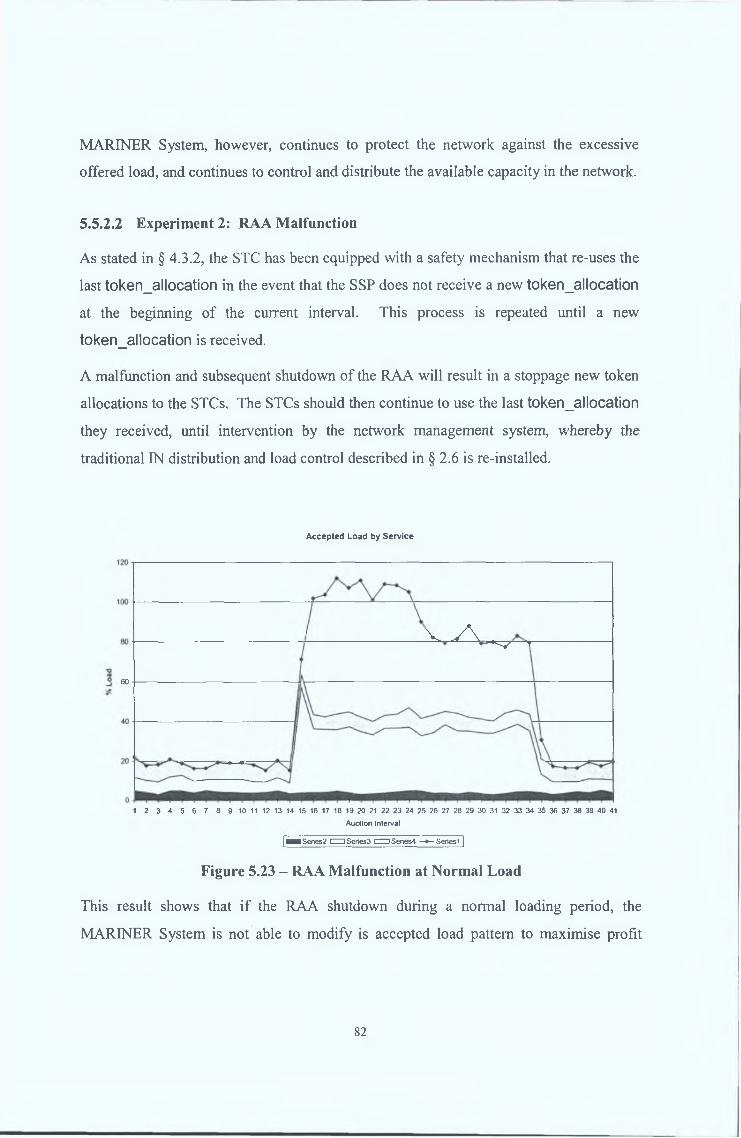
MARINER System, however, continues to protect the network against the excessive
offered load, and continues to control and distribute the available capacity in the network.
5.5.2.2 Experiment 2: RAA Malfunction
As stated in § 4.3.2, the STC has been equipped with a safety mechanism that re-uses the
last token_allocation in the event that the SSP does not receive a new token_allocation
at the beginning of the current interval. This process is repeated until a new
token_allocation is received.
A malfunction and subsequent shutdown of the RAA will result in a stoppage new token
allocations to the STCs. The STCs should then continue to use the last token_allocation
they received, until intervention by the network management system, whereby the
traditional IN distribution and load control described in § 2.6 is re-installed.
Accepted Load by Service
60
' V v \ .— ^ T
1 2 3 4 5 6 7 8 9 10 11 12 13 14 15 16 17 18 19 20 21 22 23 24 25 26 27 28 29 30 31 32 33 34 35 36 37 38 39 40 41
Auction interval
I — Series2 CZU Series3 cm Series4 —» - Series 1 ]
Figure 5.23 - RAA Malfunction at Normal Load
This result shows that if the RAA shutdown during a normal loading period, the
MARINER System is not able to modify is accepted load pattern to maximise profit
82
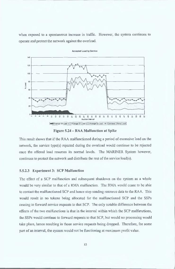
when exposed to a spontaneous increase in traffic. However, the system continues to
operate and protect the network against the overload.
Accepted Load by Service
140 ---------------------------------------------------------------------------------------------------------------------
Auction Interval
|^■ A ve rage SO Load CZJAverage S1 Load CZZ)Average S2 Load Estimated Offered Load |
Figure 5.24 - RAA Malfunction at Spike
This result shows that if the RAA malfunctioned during a period of excessive load on the
network, the service type(s) rejected during the overload would continue to be rejected
once the offered load resumes its normal levels. The MARINER System however,
continues to protect the network and distribute the rest of the service load(s).
5.5.2.3 Experiment 3: SCP Malfunction
The effect of a SCP malfunction and subsequent shutdown on the system as a whole
would be very similar to that of a RMA malfunction. The RMA would cease to be able
to contact the malfunctioned SCP and hence stop sending resource data to the RAA. This
would result in no tokens being allocated for the malfunctioned SCP and the SSPs
ceasing to forward service requests to that SCP. The only notable difference between the
effects of the two malfunctions is that in the interval within which the SCP malfunctions,
the SSPs would continue to forward requests to that SCP, but would no processing would
take place, hence resulting in those service requests being dropped. Therefore, for some
part of an interval, the system would not be functioning at maximum profit value.
83
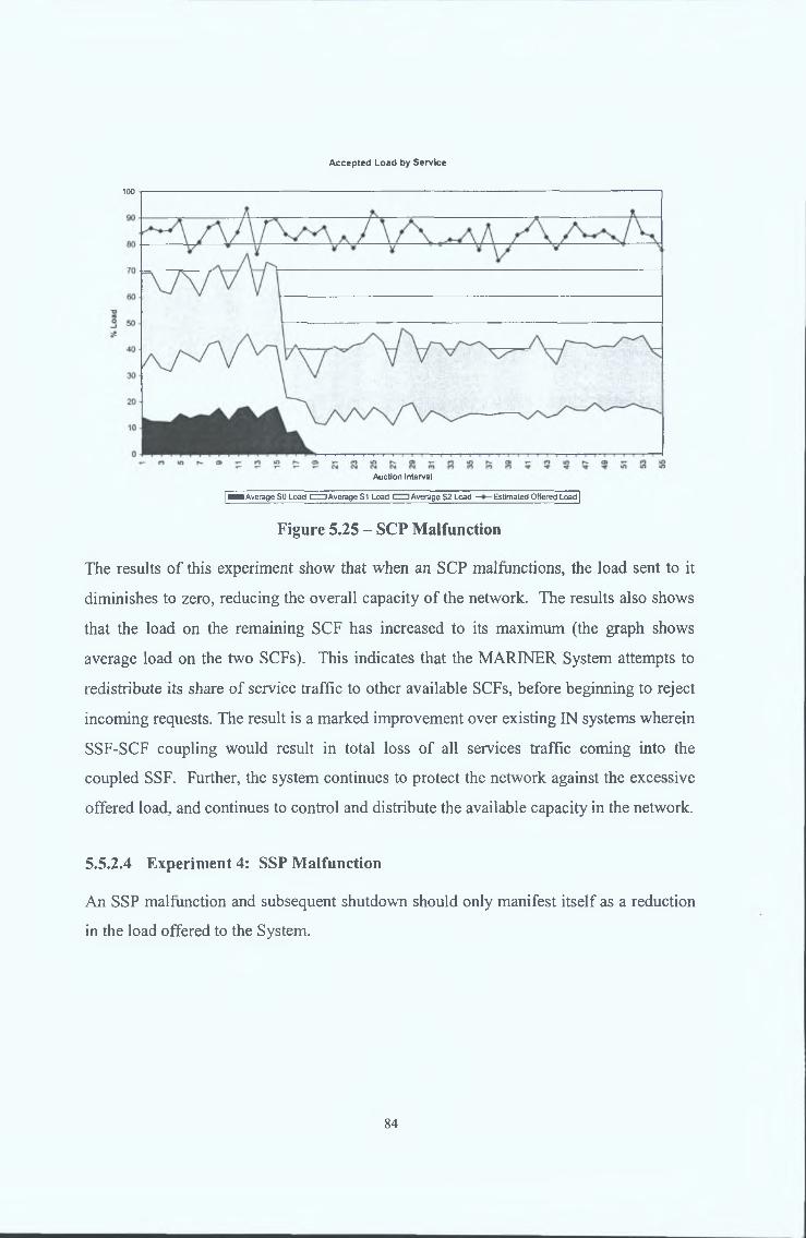
Accepted Load by Service
100
Auction Interval
| ■ ■ Average SO Load CZZ] Average S1 Load d Z ) Average S2 Load — Estimated Offered Load |
Figure 5.25 - SCP Malfunction
The results of this experiment show that when an SCP malfunctions, the load sent to it
diminishes to zero, reducing the overall capacity of the network. The results also shows
that the load on the remaining SCF has increased to its maximum (the graph shows
average load on the two SCFs). This indicates that the MARINER System attempts to
redistribute its share of service traffic to other available SCFs, before beginning to reject
incoming requests. The result is a marked improvement over existing IN systems wherein
SSF-SCF coupling would result in total loss of all services traffic coming into the
coupled SSF. Further, the system continues to protect the network against the excessive
offered load, and continues to control and distribute the available capacity in the network.
5.5.2.4 Experiment 4: SSP Malfunction
An SSP malfunction and subsequent shutdown should only manifest itself as a reduction
in the load offered to the System.
84

Accepted Load by Service
100
1 2 3 4 5 6 7 8 9 10 11 12 13 14 15 16 17 18 19 20 21 22
Auction Interval
|— Average SO Load IZ U Average S1 Load CZJ Average S2 Load —» - Estimated Offered Load |
Figure 5.26 - SSP Malfunction
The result shows that if an SSP malfunctions, the overall load offered to the network is
reduced. However, the MARINER System continues to operate with the reduced offered
load.
5.5.2.5 Experiment 5: resource_data Delay
Figure 5.22 shows that the MARINER System suffers from no adverse effects in the
event that a resource_data messages are not available for one or more intervals.
In the event of a delay in the resource_data from a RMA, the capacity of the SCP it
represents is not made available to the SSPs for that interval. Further, the portion of
requests it received from the SSPs during the last interval is not taken into account during
the token allocation process. This would result in the SSPs receiving fewer tokens for the
next interval, and hence possible rejecting service requests.
5.5.2.6 Experiment 6: token_allocation Delay
A delay in a token_allocation message from an RMA to an STC has no effect on the
MARINER System’s ability to operate successfully due to the built in redundancy
provided by more than one RMA sending a token allocation message to an STC.
85

5.5.2.7 Experiment 7: resource_data Message Loss
Figure 5.22 shows that the MARINER System suffers from no adverse effects in the
event that resource_data messages are not available for one or more intervals.
In the event of a loss of the resource_data from a RMA, the capacity of the SCP it
represents is not made available to the SSPs for that interval. Further, the portion of
requests it received from the SSPs during the last interval is not taken into account during
the token allocation process. This would result in the SSPs receiving fewer tokens for the
next interval, and hence possible rejecting service requests.
5.5.2.8 Experiment 8: token_allocation Message Loss
A loss of a token_allocation message has no effect on the MARINER System’s ability
to operate successfully due to the built in redundancy provided by the RAA sending the
complete token_allocation message to all RMAs, and more than one RMA sending a
token_allocation message to an STC.
5.5.2.9 Experiment 9: notification Message Loss
A loss in a notification message from an STC has no effect on the MARINER System’s
ability to operate successfully due to the built in redundancy provided by the STC
broadcasting its notifications to all the RMAs in its vicinity.
5.5.2.10 Experiment 10: token_allocation_ack Message Loss
A loss in a token_allocation_ack message from an STC has no effect on the MARINER
System’s ability to operate successfully due to the built in redundancy provided by the
STC broadcasting its token_allocation_acks to all the RMAs in its vicinity.
86

The criteria used to evaluate MARINER System as a network orientated load control
mechanism for the Intelligent Network was set out in § 5.1. With respect to the
experiments described in § 5.3 to § 5.5, these criteria may be expressed as the following:
1. Overload Protection: To limit the load at all SCF nodes to 90% of its processing
capacity
2. Overload Protection: To rapidly adapt to changes in the offered load.
3. Load Distribution: To distribute the load offered to the network such that the
individual SCF loads are as close as possible to the average SCF load
4. Service Differentiation: To continuously maintain the accepted load at the level of the
offered load in normal loading conditions and to reject the service requests according
to their profit value in excessive loading conditions, so as to maximise the overall
network profit at all times
5. Robustness: To maintain a minimum operating performance matching that of existing
IN Load Control mechanisms (see § 2.6) in the event of a malfunction or
communication errors
The various experimental results described in § 5.3 to § 5.5 demonstrated the degree to
which the above criteria had been met by the MARINER System and highlighted areas
requiring improvement. A summary of this is listed below:
■ § 5.4.2.1 demonstrated that under normal loading conditions, the MARINER System
successfully meets criteria 2, 3 and 4 in that the all the offered load is accepted into
the IN and evenly distributed among the available SCFs
■ § 5.4.2.2 and § 5.4.2.3 showed that under heavy loading conditions, the MARINER
System meet criteria 1 through 4. However accepted loads closer to the 90% level
would be more desirable, and better usage of notifications is seen as one method of
overcoming this limitation.
5.6 S u m m a r y
87

■ § 5.4.2.4 through § 5.4.2.6 demonstrate the sensitivity of the MARINER System to a
sudden increase in network-wide and local offered load. The results specifically
illustrate the success of the system in achieving criterion 2, while still satisfying
criteria 1, 3 and 4. The results also highlight a short lapse is in the recovery time to a
sudden decrease in offered load.
■ § 5.5.2.1 through § 5.5.2.4 show that the system meets criterion 5 in the event of the
loss of any of the IN or system functional entities.
■ § 5.5.2.5 through § 5.5.2.10 show that the system meets criterion 5 in the event of any
degree of communication loss between its functional entities.
Current and future work on the Trial Platform intends to investigates the following
possibilities:
■ Investigating more effective use of the notification messages to enable the system to
better achieve the 90% resource usage limit in all excessive load scenarios.
■ Investigating a more scalable system that utilises a hierarchical approach for the
control of large systems i.e. local network RAA’s behaving as RMA’s in larger
networks and sending monitoring data to a central RAA.
■ Investigating a more flexible system with STC’s incorporated within H.323
Gatekeepers and GSM Switches.
88

6 CONCLUSION AND FUTURE WORK
6.1 I n t r o d u c t io n
In order to complete the analysis of the performance of the MARINER Load Control
System, it is necessary to compare it with one or more other IN load control strategies.
The following criteria was used to select the IN Load Control Systems that were used for
this comparison:
1. The comparison system must implement one or more load control strategies for
Intelligent Networks
2. In order for an accurate comparison to be made, the comparison system must be
well defined by publicly available documentation, specifically in the areas of its
performance in the areas of overload protection and load control.
3. In order to ensure that the performance of the MARINER System is analysed
against a commercially deployed load control system, at least one of the
comparison systems must have been deployed on an existing commercial
Intelligent Network
4. In order to ensure that the performance of the MARINER System is analysed
against similar advanced load control systems, at least one of the comparison
systems must utilise adaptive load control strategies, and attempt to maximise
generated revenue/profit.
Based on these criteria, the following systems were selected for comparison. The
Automatic Call Restriction load control system that is currently deployed in the BT
Horizon Intelligent Network was selected due to the fact that it meets criteria 1, 2 and 3.
It has been well documented in [Williams94] and [Williams2002]. The Global IN
Control Strategy which is an adaptive load control system that seeks to maximise
revenue/profit generation, was selected due to the fact that it meets criteria 1, 2 and 4. It
is well documented in [Lodge99] and [Lodge2000]. Additionally, the standard Intelligent
Network Load Control mechanisms, as described in Chapter 2, were also selected due to
89

the fact these mechanisms have been standardised and feature in most current
implementation of Intelligent Networks.
In order to ensure a fair comparison, the criteria used for evaluating the MARINER
System, as stated in Section 5.1.1, is used as the comparison criteria.
Sections 6.2 to 6.5 give an overview of each system and specify their behaviour against
each of the comparison criteria. Section 6.6 then presents a table, comparing the load
control systems. Finally, Section 6.7 draws conclusions from this body of work, and
Section 6.8 states the on-going future work that extend from this platform.
6.2 S t a n d a r d IN L o a d C o n t r o l
As described in Chapter 2, standard IN-CS2 load control comprises mainly the Code
Gapping and Service Filtering mechanisms. These mechanisms have the following
features:
• Standardised - the Code Gapping and Service Filtering mechanisms have been
standardised in the IN Capability Set 2.
• Reliable - existing mechanisms have been tried and tested on existing INs, and
further developed based on real performance data
• Node-orientated - an overloaded SCF informs the SSF its coupled with to begin
blocking incoming requests. The state of the network as a whole is never consulted
prior to load shedding.
• Message-orientated - on the activation of either mechanism, the SSF throttles INAP
messages required for service execution, and not the service requests themselves.
• Non-prioritised - these mechanisms are incapable of differentiating between services,
since they operate on the Functional Plane.
• Static - the current mechanisms utilise static parameters to control traffic load,
therefore they cannot provide optimal control in all traffic conditions, with the result
that they tend to cause oscillations in resource utilisation.
90

• Reactive - current mechanisms react to a resource overload after it has commenced,
rather than ensuring that traffic is prevented from gaining access to the resource in
instances where it would cause one or more resources to overload
6.2.1 Overload Protection
As described in § 2.6, standard IN load control protects the network against prolonged
overloads of single nodes through the gapping of incoming messages. This allows the
node to process its existing queues, and hence reduce its load. When offered a steady
load exceeding the safe maximum network capacity, standard IN load control
mechanisms would be able to maintain the average accepted load at the safe maximum.
However, due to use of standard gap intervals, the accepted load will oscillate around the
safe maximum.
Further, due to the fact that these load control mechanisms require the onset of an
overload before sending the gapping requests, they would not be able to react to spiky or
rapidly changing offered load, which could lead to at least one interval where the SCP is
exposed to an overload.
6.2.2 Load Distribution
In standard INs, SSFs and SCFs are nearly always coupled, forming networks of mated
pairs [ETSI_SUB]. Hence, little or no load distribution is implemented.
6.2.3 Service Differentiation
As described in § 2.6, standard IN load control mechanisms operate in the Distributed
Functional Plane, hence gapping or quenching messages, irrelevant of the service type
they perform. This prevents these mechanisms from being able to differentiate between
service types.
91
The Global IN Control Strategy (GCS) involves the formulation of mathematical
optimisation problems whose solution defines the best possible coefficient values to be
used by a percentage thinning load throttle residing at SSPs. The optimisation involves
the maximisation of generated revenue subject to load constraints on SCPs and SSPs, as
well as constraints to ensure that pre-defined weightings (similar to service profit)
between service types are reflected in the percentage thinning coefficients.
The strategy consists of two independent optimisation processes, one operating at the
SCP and the other at SSPs. At set intervals the SCP optimisation process is invoked and
takes as input estimations of IN service request arrival rates at SSPs for the coming
interval, SCP target utilisation, service type weights and other service-related
information. It outputs percentage thinning coefficients for each IN service type / SSP
pairing in the network. These values are transferred to the SSPs, which use them as inputs
into their optimisation processes. SSP optimisation may serve to modify the percentage
thinning coefficients in light of local loading constraints and estimated arrival rates and
processing requirements of non-IN service types. Full details of this process can be
found in [Lodge99], [Lodge2000].
6.3.1 Overload Protection
In § 6.3.1 of [Lodge2000], an extensive set of simulation results clearly illustrate the
behaviour of the GCS with respect to steady-state Overload Protection. Figure 6.3 shows
that when exposed to a steady offered load of 120%, GCS maintains the SCP load at safe
maximum threshold. However, some oscillation is apparent around safe maximum due to
use of percentage thinning as load throttle
In § 6.3.5 of [Lodge2000], simulation results show the behaviour of the GCS when
exposed to spiky traffic, where the offered load rapidly alternates between 60% and
120%. Figure 6.29 shows that in this scenario, the GCS requires up to one interval to
adapt the percentage thinning throttle values, leading to a short period where the SCP is
exposed to the overload with the onset of the spike and a short period of excessive service
rejection after each spike.
6 .3 G l o b a l IN C o n t r o l S t r a t e g y
92
Figure 6.29 also shows that when the offered load is within the safe maximum threshold,
the SCP load matches it.
6.3.2 Load Distribution
The GCS does not have any load distribution capabilities, and operates specifically to
control the load on a single resource.
6.3.3 Service Differentiation
Figures 6.6 and 6.32 in § 6.3 of [Lodge2000] illustrates that GCS is able to differentiate
between service to maximise revenue generation in both a steady overload of 120% and
spiky traffic, where the offered load rapidly alternates between 60% and 120% of the
network capacity.
6.4 A u t o m a t ic C a l l R e s t r ic t io n
The Automatic Call Restriction (ACR) control uses the rate of call failure in the SCP to
detect overload. The control enforces an upper limit to this rate by activation and
updating of call restrictions at the SSPs. It also distinguishes between call streams such
that restrictions are only applied to the call stream causing an overload (service fairness),
before they are applied to other call streams. This control uses leaky bucket monitors at
the SCP to monitor the rate of call rejection by call stream, and based on these values,
calculates appropriate call gaps, which are communicated to the SSPs.
The ACR control also attempts to control outbound traffic from the SCPs to other
network destinations, to control the demand sent to the network, by monitoring the call
rejection rates to these destinations. Full details of this process can be found in
[Williams94], [Williams2002].
§ 6.3 of [Williams2002] evaluates the performance of ACR using an experiment that
simulates an offered SCP load of 100%, which rapidly increases to over 300% due to the
failure of another SCP in the simulated network, and then decreases back to 100% when
93

the failed SCP recovers. The result of this experiment is used to evaluate the
performance of ACR with respect to the evaluation criteria set out in § 5.1.1 of this paper:
6.4.1 Overload Protection
Figure 7 in § 6.3 of [Williams2002] shows that when the SCP is exposed to a steady
offered load of 300%, ACR successfully maintains the SCP load at the safe maximum
threshold.
This figure also illustrates that at the onset and the end of the overload, ACR is not able
to immediately respond the change in the offered load, leading to under-control and over
control.
With respect to the behaviour of ACR when the offered load is within the safe maximum
network capacity, Figure 7 shows that accepted load matches the offered load before and
after the overload.
6.4.2 Load Distribution
ACR does not have any load distribution capabilities, and operates specifically to control
the load on a single resource. However, it does have the capability of operating in
tandem with an external load distribution system.
6.4.3 Service Differentiation
The ACR implements service fairness and hence does not attempt to distinguish between
services for the maximisation of network profit.
6.5 T h e MARINER S y s te m
As described in Chapter 4, the MARINER System is a network-orientated load control
mechanism developed for the IN by the MARINER Project. It has the following
characteristics:
• Standard-compliant - the system was designed in compliance to IN CS-2, but is not
itself part of any existing standard.
94

• Non-tested - the system has only been tested on an emulation of the IN.
• Network Orientated - the system monitors all nodes in its domain and distributes
traffic evenly between the available nodes such that traffic load is only shed when the
whole network is operating at maximum capacity. In this manner individual node
protection is still maintained.
• Proactive - the system uses a network wide view of the IN to discern the onset of an
overload, and takes measures to distribute and control the incoming traffic.
• Adaptive - the control parameters of the system continuously adapt to the latest
network conditions. This allows it to always have a realistic view of network usage
and incoming traffic.
• Service-orientated - the system operates at the application level, controlling and
distributing service requests according to the service type and its importance to the
operator.
6.5.1 Overload Protection
The experimental results described § 5.4.2.2 through 5.4.2.6 show how the MARINER
System protects nodes from overloads by sensing increases in service traffic and
proactively distributing the load across the network, so as to avoid the need of load
shedding until all capacity within the network has been utilised. It then sheds load by
rejecting service requests at the SSFs.
Figures 5.9 and 5.12 illustrate that the MARINER Load Control System is successfully
able to protect the network against steady offered loads of 95% and 120%. It is observed
that a varying degree of over-control manifests itself in both scenarios. However, it is
also noted that configuring the system to use multiple notification messages would
remove this effect.
Figures 5.15 and 5.18 show that system is successfully protects the network against
sudden surges in offered load, without at any time exposing the protected nodes to an
overload. At the onset and end of the spike, a small amount of over-control is observed,
but this is rapidly corrected. %
95

Figure 5.6 shows that under normal steady offered load, the MARINER System ensures
that the accepted matches the offered load.
6.5.2 Load Distribution
Figures 5.4, 5.7, 5.10, 5.13 and 5.16 illustrate that the MARINER Load Control System is
able to successfully distribute the accepted load between the available SCPs for offered
loads of both steady and spiky in nature ranging from 35% to 120% of the network
capacity. In doing this, it allows for optimum use of all available capacity in the network.
This prevents service request rejection and loss of revenue unless all the capacity within
the network is being utilised.
Figure 5.25 shows a further advantage of load distribution in the MARINER Load
Control System in that it increases the network robustness towards the malfunction or
shutdown of a processing node by re-routing its share of traffic to other available nodes.
6.5.3 Service Differen tiation
Figures 5.6, 5.9, 5.12, 5.15 and 5.18 clearly illustrate how the MARINER System is able
to differentiate between service types in steady and bursty offered loads ranging from
35% to 120% of the network capacity. The figures also show that when forced to reject
traffic due to excessive incoming traffic, the MARINER rejects service requests of least
priority first. This facility gives network operators using the MARINER System the
following advantages:
• The ability to maximise the revenue generated from their network at all times.
• The ability to allow third-party services into their network with the confidence that
the capacity allocated to them can be regulated and limited so as to not harm their
network, in the event of irresponsible usage by the third parties.
• The ability to have Service Level Agreements automatically enforced by the network.
It should be noted that these results also further emphasize the reasons neither service-
faimess or source-faimess is used as an evaluation criterion in this paper.
96

6 .6 L o a d C o n t r o l S y s t e m C o m p a r i s o n
Criterion Standard GCS ACR MARINER
Overload
Protection:
Staying close to
but under safe
maximum
network capacity
processor target
utilisation during
overload.
NO
Accepted
Load
oscillates due
to use of
standard gap
intervals.
PARTIAL
Some oscillation
is apparent
around safe
maximum due to
use of
percentage
thinning as load
throttle
YES
Accepted Load
maintained
below safe
maximum
using variable
gap intervals
YES
Accepted Load
slightly below safe
maximum. Use of
tokens ensures safe
maximum not
exceeded.
Overload
Protection:
Immediate
reaction to
overload onset
and end.
NO
Up to one
control
interval
before gap
put in place.
NO
Up to one control
interval before
percentage
thinning in place.
NO
Up to one
control interval
before gapping
put in place.
YES
Immediate reaction
due to volume of
accepted requests
limited by token
allocation size.
Load Distribution:
Equally between
all available
SCPs offering
required service
type
NO
Mated SSF-
SCF
messaging
excludes load
distribition
NO
Operates
specifically to
control the load
on a single
resource.
NO
Operates
specifically to
control the load
on a single
resource.
YES
Use of token strategy
and manipulation of
SSF routing tables
enables load
distribution
Service
Differentiation:
Ensuring profit
maximisation
NO
Operation at
DFP
excludes
Service
Differentiation
YES
Optimization of
percentage
thinning
coefficients
allows for Service
Differentiation
NO
Adherence to
service
fairness
excludes any
Service
Differentiation
YES
Tokens generated so
as to differentiate
between services and
maximise profit.
97

• Standard IN Load Control is insufficient due to being highly prone to oscillations
and not robust to changes in offered load due reliance on standard gap intervals.
• ACR shows that the application of dynamic sets of gap intervals shows a marked
improvement by reducing oscillation, but still lacks in the area of robustness to
bursty traffic.
• GCS performs better than standard mechanisms with respect to accepted load
oscillations and dynamically computes control parameters with the goal of
maximising profit whilst protecting the SCP from overload.
• MARINER matches the performance of ACR and GCS in the areas of steady state
overload protection and service differentiation respectively, but out-performs all the
comparison strategies in robustness to rapid changes in the offered load and load
distribution.
6.7 C o n c lu s io n
The completion of this assessment of network-orientated load control has shown that it
offers the following advantages over existing Intelligent Network Load Control and
Overload Protection Systems:
• It protects network nodes in a proactive manner; resulting in an immediate reaction to
sudden changes in the offered load and, in an overload, complete utilisation of the
network capacity, without endangering the network resources.
• It offers load distribution capabilities to the operator
• It allows the operator to prioritise services, improving their ability to maximize
network profit and honor Service Level Agreements.
At the same time, the following limitations of the mechanism have been unveiled:
• The over-protection of network resources when exposed to an offered load slightly
over the safe maximum network capacity.
This comparative analysis of the four strategies shows the following:
98

• The lack of a standard manner of implementing network-orientated load control
• The lack of performance data from real Intelligent Networks
Finally, it was shown that the MARINER System, as an implementation of a network-
orientated load control system, out performed existing representative implementations of
standard, traditional and more advanced Intelligent Network load control systems in the
areas of overload protection, load distribution and service differentiation.
In summary, network-orientated load control is a definite enhancement over existing load
control mechanisms for Intelligent Networks. However, it needs to be standardized and
through those efforts, further tested and validated on real networks.
6 .8 F u t u r e W o r k
The following is an overview of the development and enhancement work being explored
and implemented on network orientated load control systems.
6.8.1 Multiple Notification Investigation
In response to the tendency of the MARINER System to over-protect the network
resources when exposed to traffic loads slightly over the safe maximum network
capacity, investigations are being carried out on the use of multiple notification messages
from the STC to the RMA, resulting in a reduction of the inaccuracy of single
notifications and the RAA being better informed about the traffic situation prior to the
auctions.
6.8.2 Standardisation Activities
A submission [ETSI SUB] has been made to ETSI in order to initiate the standardisation
of network orientated load control systems. The response has been encouraging, with
more detailed presentations to the Working Groups planned in the months ahead.
99

6.8.3 Scalability
Further trials on the MARINER System are being designed in order to evaluate the
scalability of network orientated load control. In a large network, it is envisioned that
hierarchical auctions would be held, where RAAs would participate in auctions, playing
the role of RMAs of their local sub-network. Each layer would then have its own RAA.
The areas that are being investigated are the optimum number of agents per layer; the
efficiency of the tree-like structure; efficient methods of combining the RAA and RMA
roles in sub-network RAAs.
6.8.4 Distributed SCF Load Control
Recently, there has been much work in exploring the possibility of splitting the IN SCF
functionality into separate CORBA objects distributed across the network. Currently,
investigations are being carried out on the possible of using the network-orientated load
control to efficiently cope with the traffic demands on these distributed SCFs.
6.8.5 Internet Telephony
The usage of network-orientated load control for Internet Telephony is also being
explored. Possible methods of controlling the load on Internet Telephony Gatekeeper
and Gateway resources are described in the paper [Wathanl999].
100

GLOSSARY
CORBA Common Object Request Broker Architecture
CS-1 Capability Set 1
CS-2 Capability Set 2
DFP (INCM) Distributed Functional Plane
ETSI European Telecommunications Standards Institute
EURESCOM European Institute for Research and Strategic Studies in
T elecommunication
FE Functional Entity
GFP (INCM) Global Functional Plane
GSM Global System for Mobiles
GPRS General Packet Radio Service
IDL Interface Definition Language
IN Intelligent Network
INAP Intelligent Network Application Protocol
INCM Intelligent Network Conceptual Model
ITU-T International Telecommunication Union - Telecommunication
Standardisation Sector
MARINER Multi-Agent Architecture for Distributed IN Load Control and
Overload Protection
0 0 Object Orientation
PP (INCM) Physical Plane
CAMEL Customised Applications for Mobile Network Enhanced Logic
RAA Resource Allocation Agent
101
SCF Service Control Function
SCP Service Control Point
SIB Service-Independent Building Block
SP (INCM) Service Plane
SSF Service Switching Function
SSP Service Switching Point
STC Service Traffic Controller
TIPHON Telecommunications and Internet Protocol Harmonisation over
Networks
VPN Virtual Private Network
RMA Resource Management Agent
102
REFERENCES
[Arvidsson97] A. Arvidsson, S. Pettersson and L. Angelin, “Profit Optimal Congestion
Control in Intelligent Networks”, in Proceedings of the 15th International Teletraffic
Congress, pp. 911-920, Washington D. C., USA, 1997.
[Arvidsson99] A. Arvidsson, B. Jennings, L. Angelin and M. Svensson, “On the use of
Agent Technology for IN Load Control”, in Proceedings of the 16th International
Teletraffic Congress (ITC-16), vol. 3b, pp. 1093-1105, Edinburgh, Scotland, June 1999.
[CORBA] Object Management Group (OMG), “The Common Object Request Broker
(CORBA): Architecture and Specification ”, Revision 2.0, July 1995.
[Dovrolis2000] C. Dovrolis, P. Ramanathann, “Proportional Differentiated Services, Part
II: Loss Rate Differentiation and Packet Dropping”, in Proceedings of IEEE/IFIP
International Workshop on Quality of Service (IWQoS), pp. 53-61, Pittsburgh PA,
U.S.A, June 2000.
[ETSI_SUB] B. Jennings, N. Wathan, R. Brennan and C. Smith, “Network-oriented
Load Control for IN: Benefits and Requirements”, Submission to ETSI SPAN on behalf
of the ACTS-MARINER project, May 2000.
[Fayn96] I. Faynberg, L. Gabuzda, M. Kaplan, and N. Shah, “Intelligent Network
Standards: their Application to Services”, pub. McGraw Hill, New York, U.S.A, 1997
[Folkestad96] A. Folkestad, P. Osland and P. Emstad, “On Load Control for Service Data
Points”, in Proceedings of the 4th International Conference on Intelligence in Networks,
Bordeaux, France, November 1996.
[Galletti92] M. Galletti, F. Grossini, "Performance Simulation of Congestion Control
Mechanisms for Intelligent Networks", in Proceedings of 1992 International Zurich
Seminar on Digital Communications, Intelligent Networks and their Applications, Zurich,
Switzerland, 1992.
[GRASSHOPPER] IKV++, “Grasshopper Basics and Concepts”, release 1.1 Feb 1999,
available (Sept 2000): http://www.grasshopper.de/index.html
103

[Hac98] A. Hac and L. Gao, “Analysis of Congestion Control Mechanisms in an
Intelligent Network”, International Journal of Network Management, vol. 8, pp. 18-41,
1998.
[Hnatyshin2001 ] V. Hnatyshin and A.S. Sethi, “Avoiding Congestion Through Dynamic
Load Control”, Proc. ITCom-2001, SPIE's International Symposium on The Convergence
of Information Technologies and Communications, CO pp. 309-323, Denver, U.S.A, Aug
2001
[Kant95] K. Kant, "Performance of Internal Overload Controls in Large Switches", I
Proceedings of the 28th Annual Simulation Conference, pp 228-237, Phoenix, U.S.A,
April 1995
[KhorasaniO 1 ] Mehdi Khorasani, Dr. Lionel Sacks, “Integrity: An Interaction Case
Study”, in Proceedings of the London Communications Symposium, London, United
Kingdom, September 2001.
[Kihl99] Maria Kihl, “Overload control strategies for distributed communication
networks”, PhD. Thesis, Faculty of Technology, Lund University, Lund, Sweden, March
1999.
[Komer91] Ulf Komer, “Overload Control of SPC Systems” in Proceedings of the 13th
International Teletraffic Congress, Copenhagen, Denmark, 1991.
[Komer94] U. Komer, C. Nyberg and B. Wallström, “The Impact of New Services and
New Control Architectures on Overload Control”, in Proceedings of the 14th
International Teletraffic Congress, pp. 275-283, Antibes Juan-les-Pins, France, 1994
[Kwiatkowski94] M. Kwiatkowski, B. Northcote, “Calculating Mean Delays in
Intelligent Networks Under Overload”, in Proceedings of the Australian
Telecommunication Networks and Applications Conference (ATNAC), Melbourne,
Australia, December 1994.
[Langlois91] F. Langlois, J. Regnier, “Dynamic Congestion Control in Circuit-Switched
Telecommunications Networks”, in Proceedings of the 13th International Teletraffic
Congress (ITC 13), Copenhagen, Denmark, 1991.
104

[Lodge97] F. Lodge, D. Botvich, T. Curran, “A fair algorithm for throttling combined IN
and non-IN traffic at the SSP of the Intelligent Network”, in Proceedings of IEEE
Teletraffic Symposium, Manchester, United Kingdom, March 1997.
[Lodge99] F. Lodge, D. Botvich and T. Curran, “Using Revenue Optimisation for the
Maximisation of Intelligent Network Performance”, in Proceedings of the 16th
International Teletraffic Congress, pp. 953-965, Edinburgh, Scotland, June 1999.
[Lodge2000] F. Lodge, “An Investigation into Intelligent Network Congestion Control
Techniques”, PhD. Thesis, School of Electronic Engineering, Dublin City University,
Ireland, 2000.
[MAGEDANZ96] T. Magedanz, R. Popescu-Zeletin, “Intelligent Networks: Basic
Technology, Standards and Evolution“, International Thomson Computer Press, 1996
[MARINER] ACTS-MARINER Project Consortium, “The European Commission’s
Advanced Communication, Technologies and Services (ACTS) Multi-Agent Architecture
for Distributed Intelligent Network Load Control and Overload Protection (MARINER)
Project”, available (Sept 2000): http://www.cordis.lu/infowin/acts/rus/projects/ac333.htm
[MARINERD4] ACTS MARINER Project Consortium, “MARINER Deliverable 4:
Specification of Final IN Load Control Strategy and Multi-Agent System for deployment
on Trial Platform”, May 1999, available (Sept 2000): http://www.teltec.dcu.ie/mariner
[MARINERD8] ACTS MARINER Project Consortium, “MARINER Deliverable 8”,
May 2000, available (Sept 2000): http://www.teltec.dcu.ie/mariner
[MASIF] Object Management Group (OMG), “Mobile Agent System Interoperability
Facility”, Revision 1.1, 1998
[Mine98] Roberto Minerva, Corrado Moiso, Gabriele Viviani, “The Middleware ate the
Verge between Internet and Telecom Services”, in Proceedings of the 5th International
Conference on Intelligence in Networks, Bordeaux, France, May 1998
[Mohapi2000] S. Mohapi and H.E. Hanrahan, “Value-based service differentiation for
distributed NGN service platforms”, in Proceedings of the South African
Telecommunications Networks and Applications Conference, Drakensberg, South Africa,
September 2002
105

[Nyberg94] H. Nyberg and B. Olin, “On load control of an SCP in the Intelligent
Network”, in Proceedings of the Australian Telecommunication Network and
Applications Conference, Melbourne, Australia, December 1994.
[P8132000] “Technical Development and Support for European ATM Service
Introduction”, P813 Project Deliverable 5 Recommendations on Traffic-related
Implementation Issues Volume 1 of 4, February 2000.
[P916] EURECOM P916 Project Consortium, “Supporting of H.323 by IN”, available
(Sept 2000): http://www.eurescom.de/public/proiects/P900-series/P916/P916.htm.
[Pettersson96] S. Pettersson, “Some Results on Optimal Decisions in Network Oriented
Load Control in Signaling Networks”, University of Karlskrona/Ronneby Technical
Report, ISRN HKR-RES-96/11-SE, Karlskrona, Sweden, 1996
[Q1200] ITU-T, “General Series Intelligent Network Recommendation Structure”
(Recommendation Q.1200), ITU-T, 1999
[Q1201] ITU-T, “Principles of Intelligent Network Architecture”(Recommendation
Q.1201), ITU-T, 1993
[Q1202] ITU-T, “Intelligent Network - Service Plane Architecture”(Recommendation
Q.1202), ITU-T, 1998
[Q1203] ITU-T, “Intelligent Network - Global Functional Plane Architecture”
(Recommendation Q.1203), ITU-T, 1998
[Q1204] ITU-T, “Intelligent Network Distributed Functional Plane Architecture”
(Recommendation Q. 1204), ITU-T, 1993
[Q1205] ITU-T, “Intelligent Network Physical Plane Architecture” (Recommendation
Q.1205), ITU-T, 1993
[Q1208] ITU-T, “General Aspects of the Intelligent Network Application Protocol ”
(Recommendation Q.1208), ITU-T, 1998
[Q1222] ITU-T, “Service Plane for Intelligent Network Capability Set 2”
(Recommendation Q.1222), ITU-T, 1998
106

[Q1223] ITU-T, “Global Functional Plane for Intelligent Network Capability Set 2”
(Recommendation Q.1223), ITU-T, 1998
[Q1224] ITU-T, “Distributed Functional Plane for Intelligent Network Capability Set 2”
(Recommendation Q. 1224), ITU-T, 1998
[Q1228] ITU-T, “Interface Recommendation for Intelligent Network Capability Set 2”
(Recommendation Q.1228), ITU-T, 1999
[Q771] ITU-T, “Signalling System No. 7 - Functional Description of Transaction
Capabilities” (Recommendation Q.771), ITU-T, 1994.
[Rajaratnam96] M. Rajaratnam, F. Takawira, “Modelling multiple Traffic Streams
Subject to Trunk Reservation in Circuit-Switched Networks”, in Proceedings of IEEE
GLOBECOM 1996, Sydney, Australia, November 1996.
[Rumsewicz96] M. Rumsewicz, “A simple and effective algorithm for the protection of
services during SCP overload”, in Proceedings of the 4th International Conference on
Telecommunications Systems, Nashville, U.S.A, March 1996.
[Sabourin91] T. Sabourin, G. Fiche, M. Ligeour, "Overload Control in a Distributed
System", in Proceedings of the 13th International Teletraffic Congress (ITC 13), pp 421-
427, Copenhagen, Denmark, 1991.
[TIPHON] ETSI TIPHON Project, “The European Telecommunications Standards
Institute Telecommunications and Internet Protocol Harmonization Over Networks
Project”, available (Sept 2000): http://www.etsi.org.
[Tsolas92] N. Tsolas, G. Abdo, R. Bottheim, “Performance and Overload Considerations
when Introducing IN into an Existing Network”, in Proceedings of International Zurich
Seminar on Digital Communications, Zurich, Switzerland, 1992.
[Vasic99] J. Vasic, “The Internet Integrated Intelligent Network”, MSc. Thesis, School of
Electronic Engineering, Dublin City University, Ireland, 1999.
[Wathan99] Navin Wathan, Brendan Jennings, Dr. Thomas Curran, “Application of
MARINER Agents to Load Control in IP Telephony Networks”, in Proceedings of the
ACTS CAMELEON Workshop, Karlskrona, Sweden, September 1999.
107

[Wathan2000] Navin Wathan, Dr. Thomas Curran, “The MARINER Trial Platform: A
Model of a Load Control System for Intelligent Networks”, in Proceedings of IEEE
International Conference On Networks (ICON) 2000, Singapore, September 2000.
[Williams94] P M Williams, ‘A novel automatic call restriction scheme for control of
focused overloads’, in Proceedings of the 11th UK IEEE Teletraffic Symposium,
Cambridge, United Kingdom, 1994.
[Williams2002] P M Williams, M J Whitehead, “Realising effective intelligent network
overload controls”, BT Technology Journal, Voi 20, July 2002.
[Whetten2000] Whetten, B. and G. Taskale, “An Overview of Reliable Multicast
Transport Protocol II”, IEEE Networks, Voi 14, pp. 37-47, January 2000.
APPENDIX A: MARINER INFORMATION FLOWS
resourcedataSenderReceiverSSPServiceRequestScfCapacity
identifier of RMA identifier of RAA2-dimensional array o f token bids by SSP/service
a double holding the SCF processing capacity
token_allocationSender identifier of RAARMAReceiver identifier of RMA/STCAllocation a three-dimensional array of token allocations, per service per SCP per SSPIntervallD integer uniquely identifying the interval for which this token_allocation is
validIntervalLength length in milliseconds of the next intervalDeladline length in milliseconds of next token generation deadline
token_allocation_ackSender identifier of STCReceiver identifier of RMAIntervallD integer uniquely identifying the interval for which this acknowledgement
relatesRelativeTime (signed) time in milliseconds before/after arrival of to k e n _ a llo c a t io n
and expiry of Timer T7 (See Figure 4.1)
108

Sender identifier of STC/RMAReceiver identifier of RMA/RAAServiceldentifier identifier of service type the notification refers toRelativeTime fraction into current interval notification generatedRejections number of sessions rejected in current interval prior to notification
I ate_d a t a_war n i n gSender identifier of RAAReceiver identifier of RMADuration time in ms that re so u rc e _ d a ta arrived late
late_alloc_warningSender identifier of RMAReceiver identifier of RAADuration time in ms that token a l lo c a t io n arrived late
notification
109

APPENDIX B: IN MODEL
B.l SSF
mainQStcOAdrnissionControlQServiceCounterQ
| SarweSunto 1 ____ IL -W JL —AdmissionControl
11i
■ IServiceLogic |
| incReqCounterQ incDpCbunterQ getReqCounterO getDpCounterO 4
incReqC
f c ; f
1------
)unter(
serviceReq(service)VoiceServiceQRingbackServiceOVPNService
1 Default StatesresourceAvailableO
TrafTicControlSemœOresourceAvailableOupdateTokens() serxJNoti ficationO*
sendAckO
7 updateTokensQ
| VoiceService jmm VPNService :'.c~ .^7 tri Ringbackiìerviee' ■■W.WWWLLPTraffieC^ntroî Service
1 Service 1 states i l l
' Servicestates
Servicestates
seiidNotificaiionQsendAckOconnect_extO
.
k i k ì \ A i "" iI •¡connect_e\10
t v ? fJ i [
—J----------------------initiatorAclrrpl
L ReceiveMessages
■
1InitiatorAc
ReceivedMessages
-> creates -O extends — -> invokes method ■ implements interface
Figure B .l - The SSF Class Diagram
110

The SSF classes and their relationships are illustrated in Figure B.l. It operates as
described in § 3.2.1. Below are the class descriptions.
B.1.1 Admission Control
The Admission Control class implements the Tglnterface. Each time the serviceReq(m
service_key) method is called, it does the following:
• It verifies the service type being requested
• It requests that the ServiceCounter increment the serviceRequestCounter of the
service type by calling incReqCounter(semce_A:e’y).
• It checks that there are resources available to execute the request by calling the
resourceAvailable(service_key) method in the Stc. It is returned either a nullAddress
or a particular scfAddress.
• If a nullAddress is received, it requests that the ServiceCounter increment the
serviceDroppedCounter of the service type by calling the mcDpCounter(service_key).
• If an scfAddress is returned, it creates the ServiceLogic class of the service type
BA.2 Initiator Ac
The InitiatorAc class is an interface class generated from a CORBA IDL file. It
simulates the INAP messages using the TcSignalling.idl interface defined in the OMG
IN/CORBA Specification. Below is the InitiatorAc IDL
interface lnitiatorAc:TcSignaling::TcUser{
oneway void request_event_report_bcsm();oneway void release_call();oneway void prompt_and_col!ect_userJnformation();oneway void connect_to_resource();oneway void initiate_call_attempt();oneway void connect();oneway void continue^);oneway void connect_ext(in lnControlAndMonitor::TokenAllocation token_allocation);
111

The InitiatorAcImpl class implements the InitiatorAc interface. An object of this class is
instantiated for every service request by a child of the ServiceLogic class representing the
service type requested. Every time a method in this class is called, it calls a method of
the same name in the ServiceLogic class e.g.
public void release_call() {
serviceLogic.releaseCall();
B.L4 RingbackService
The RingbackService class inherits from the ServiceLogic class and implements the Ssf-
side state machine illustrated § B.4.3. It receives messages through the InitiatorAcImpl
class and sends messages through the SimpleDialogHandler class.
B.1.5 ServiceCounter
The ServiceCounter class maintains two counter arrays. The reqCounter array keeps
count of the number of requests for the different service types. The dpCounter array
keeps count of the number of requests rejected by the SSF for the different service types.
This class is used by the monitoring system.
B.1.6 ServiceLogic
The ServiceLogic class is the parent class of the service execution classes and
implements the default states and error conditions for out of state messages received by
the InitiatorAc interface.
B.1.7 SimpleDialogHandler
The SimpleDialogHandler class is used to send messages to particular SCFs. This class
is instantiated by the child classes of the ServiceLogic class per service request. On
B.1.3 InitiatorAcImpl
112

instantiation, it binds to the AeFactory interface of the SCF that is assigned to execute the
particular service request. A successful bind process returns a reference to a Responder
interface. The SimpleDialogHandler then invokes calls on this interface pertaining to the
messages it is instructed to send by the service logic states.
It also instantiates a InitiatorAcImpl object and sends it to the SCF AcFactory during the
bind.
B.1.8 S s f
The Ssf class contains the main() method in the SSF. It is responsible for the following:
• It instantiates the AdmissionControl, ServiceCounter and Stc classes.
• It initialises the CORBA Orb and the Basic Object Adaptor
• It registers the Tglnterface to the Interface Repository
• It registers the interface implementation
B.1.9 Stc
The Stc class implements the Service Traffic Controller functionality described in
Chapter 4. It does the following:
• It instantiates a TrafficControlService object for each SCF in the network
• It maintains a pool of tokens for each of the service types
• It maintains a timer, set to expire every tokenAllocationlnterval
• It restarts the timer, refreshes the pool with a new tokenAllocation and calls the
sendAck(token allocation_ack) method in all TrafficControlService objects when the
\iy&dLioT6kens(tokenAllocatiori) method is called
• If no tokenAllocation is received before the timer expires, it refreshes the pool with
the last allocation
113
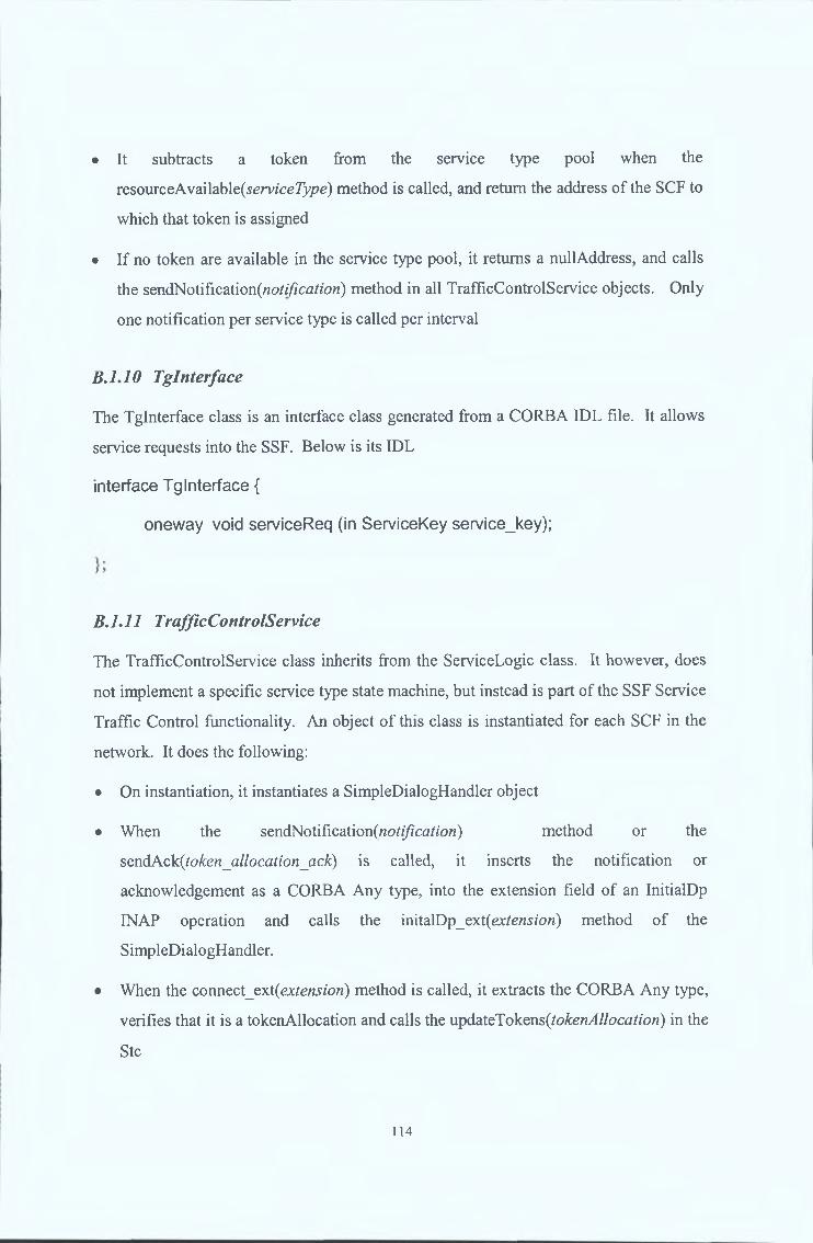
• It subtracts a token from the service type pool when the
resourceAvailable(serv/ce7);/?e) method is called, and return the address of the SCF to
which that token is assigned
• If no token are available in the service type pool, it returns a nullAddress, and calls
the sendNotification(«o///?ca^'o«) method in all TrafficControlService objects. Only
one notification per service type is called per interval
B.1.10 Tglnterface
The Tglnterface class is an interface class generated from a CORBA IDL file. It allows
service requests into the SSF. Below is its IDL
interface Tglnterface {
oneway void serviceReq (in ServiceKey service_key);
B.1.11 TrafficControlService
The TrafficControlService class inherits from the ServiceLogic class. It however, does
not implement a specific service type state machine, but instead is part of the SSF Service
Traffic Control functionality. An object of this class is instantiated for each SCF in the
network. It does the following:
• On instantiation, it instantiates a SimpleDialogHandler object
• When the sendNotification {notification) method or the
sendAck {token _allocation_ack) is called, it inserts the notification or
acknowledgement as a CORBA Any type, into the extension field of an InitialDp
INAP operation and calls the initaXDp_ext{extension) method of the
SimpleDialogHandler.
• When the connect_ext(ejctension) method is called, it extracts the CORBA Any type,
verifies that it is a tokenAllocation and calls the updateTokens{tokenAllocation) in the
Stc
114

The VoiceService class inherits from the ServiceLogic class and implements the Ssf-side
state machine illustrated § B.4.1. It receives messages through the InitiatorAcImpl class
and sends messages through the SimpleDialogHandler class.
B.1.13 VPNService
The VPNService class inherits from the ServiceLogic class and implements the Ssf-side
state machine illustrated § B.4.2. It receives messages through the InitiatorAcImpl class
and sends messages through the SimpleDialogHandler class.
B.1.12 VoiceService
115
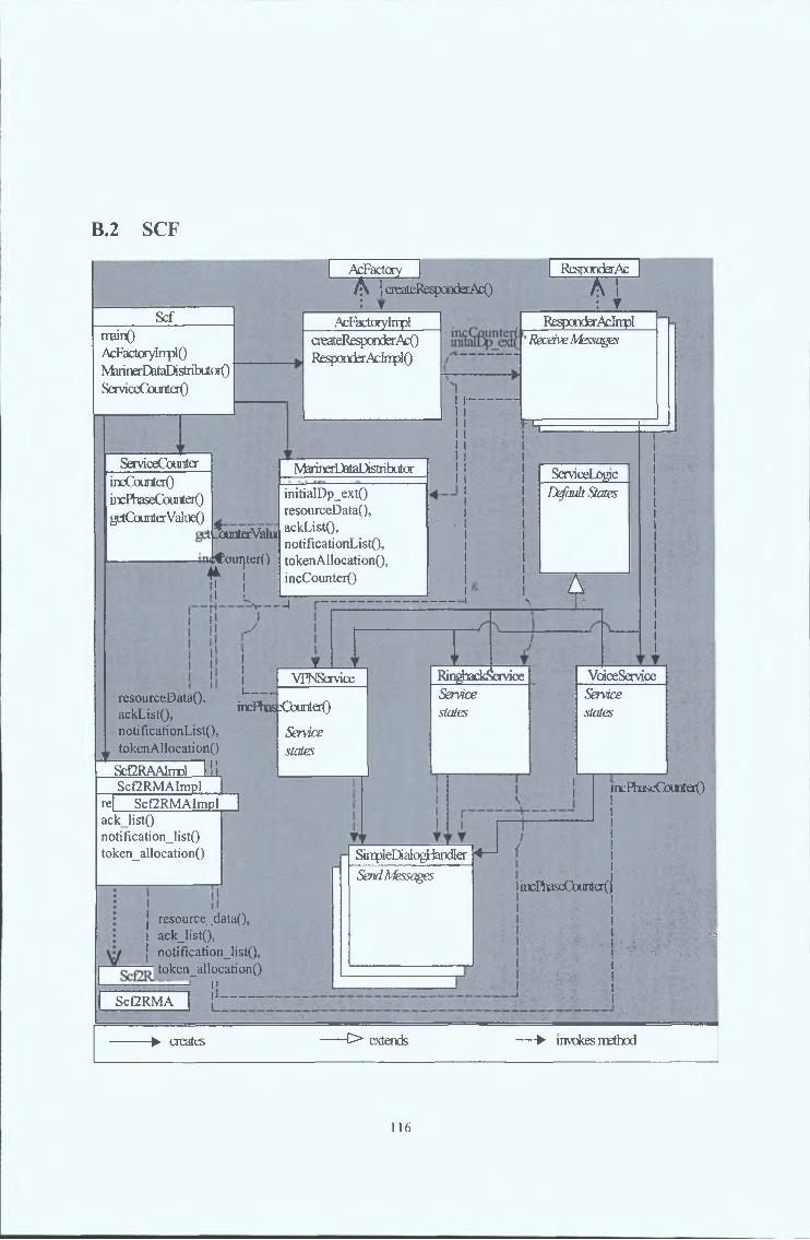
B.2 SCF
___Scf
rrainOAcFactcrylrrplONferinerD&taDistribuioit)ServiceCamterQ
AcFactory [A ! createKespœderAcO: T
ResponderAc
A !: TAcFactorylmpl
createResponderAcORespondsrAcInplO
ServiceCounterincCounterOincPbaseCounterOgetCounterValiieO
NferinerD&taDistiibiitor 1I
11| ServiceLogic
initialDp_extQ11I Default States
resourceDataQ, 1
t ÎxaterValui ackListQ, * ‘ t|
notificationListO, 1ut€cjui|ter() token AllocationO, I
1
t 1HincCounterO
4 - ! i ^ ❖
ResponderAdnplReceive Messages
H r
• 1
mVPNService
resourceDataQ,ackList(),notificationList(),tokenA11ocation()
i---incHiasfïCamterO
Service states
ScGRAAlnrol H i ,
RingbackServiceSendeestates
VoiœServiceServicestates
reScf2RMAImpl
Scf2RMAImplacklistQ notification_listO token_allocati on()
I
j resource_data(),I ack_list(), f j notification_!ist(),
' token_allocation()
¡1— _
SinpleDialogHandlerSend Messages
incPlxiseCounterO
Scf2RMA
HncPhaseCouricjO
:' ■ / • 1.; .. . -,'c V
Ml
MM
> creates -O extends — > invokes method
116

The SCF classes and their relationships are illustrated in Figure B.2. It operates as
described in § 3.2.2. Below are the class descriptions.
B.2.1 AcFactory
The AcFactory class is an interface class generated from a CORBA IDL file. It allows
service requests into the SCF. Below is the AcFactory IDL
interface AcFactory {
ResponderAc create_responder_ac(in InitiatorAc initiator_ac)
raises (TcSignaling::NoMoreAssociations);
};
B.2.2 AcFactorylmpl
The AcFactorylmpl class implements the AcFactory interface. When the
create responder method is called, it instantiates a ResponderAcImpl object and passes it
the InitiatorAc reference. It then returns the reference to the ResponderAclmpl object.
B.2.3 MarinerDataDistributor
The MarinerDataDistributor class implements the resource control functionality in the
SCF and is the communication bridge between the SSFs and the MARINER System. It
does the following:
• When the '\n\\.\dXDy_QyA.(ssfAddress, extension) method is called, it verifies that the
extension is a recognised MARINER Information Flow e.g. token allocation ack,
notification and stores the message.
• When the 'mcCo\mtex(serviceType) is called, it calls the ServiceCounter
\nCo\mtex(serviceType) method.
• When the \o\ter)A\\oc2X\on(tokenAUocation) method is called, it inserts the token
allocation into the extension field of the Connect INAP operation as a CORBA Any
Figure B.2 - The SCF Class Diagram
117

type and sends it to all the SSFs by calling the connect ext(extension) method of their
InitiatorAc interfaces
• When the getResourceData() method is called, it calls the getCounterValueQ method
of the ServiceCounter object to attain the counter values and returns it to the caller.
• When the getAckList() method is called it returns the token_allocation_acks it has
received
• When the getNotification() method is called, it returns the notifications it has received
B.2.4 ResponderAc
The ResponderAc class is an interface class generated from a CORBA IDL file. It
simulates the INAP messages using the TcSignalling.idl interface defined in the OMG
IN/CORBA Specification. Below is the ResponderAc IDL
interface ResponderAc:TcSignaling::Tcllser{
oneway void initial_dp(in ServiceKey service_key, in
lnControlAndMonitor::Ss7Address ssf_address);
oneway void initial_dp_ext(in lnControlAndMonitor::Ss7Address
ssf_address,in any extension);
oneway void event_report_bcsm();
oneway void prompt_and_collect_user_information_result();
B.2.5 ResponderAcImpl
The ResponderAcImpl class implements the ResponderAc interface. On receiving an
'm\i\d\Dy(ssfAddress, serviceKey), it verifies that the service logic for the requested
service type is available in the SCF. It returns a no implement error if the service logic is
unavailable. Otherwise, it does the following:
• It calls the 'mcCo\mter(serviceKey) method of the MarinerDataDistributor
118

• It instantiates the ServiceLogic child object that executes the requested service type
Following that, everytime it receives an INAP operation method call, it calls the
corresponding method in the ServiceLogic object.
If it receives an initialDp_ext(ss/4 ¿/dress, extension), it calls the initialDp ext method in
the MarinerDataDistributor class.
B.2.6 RingbackService
The RingbackService class inherits from the ServiceLogic class and implements the Scf-
side state machine illustrated § B.4.3. It receives messages through the
ResponderAcImpl class and sends messages through the SimpleDialogHandler class.
B.2.7 S c f
The Scf class contains the main() method in the SCF. It is responsible for the following:
• It instantiates the AcFactorylmpl, MarinerDataDistributor, Scf2RMAImpl and
ServiceCounter classes.
• It initialises the Orb and the Basic Object Adaptor
• It registers the AcFactory and Scf2RMA interfaces to the Interface Repository
• It registers the interfaces’ implementations
B.2.8 Scf2RMA
The Scf2RMA class is an interface class generated from a CORBA IDL file. It allows
the RMA to push requests and information flows to the SCF. Below is the Scf2RMA
IDL
interface Scf2RMA{
readonly attribute ResourceData resource_data;
readonly attribute NotificationList notificationjist;
readonly attribute AckList ackjist;
119

void auction_result(in AuctionResult anAuctionResult);
B.2.9 Scf2RMAImpl
The Scf2RMAImpl class implements the Scf2RMA interface. For each method call it
receives, it calls the corresponding method in the MarinerDataDistributor class.
B.2.10 ServiceCounter
The ServiceCounter class maintains counters for the number of service requests received
for each service type, and the number of service phases executed by the SCF.
• When the incCounter(serviceType) method is called, it increments the service type
requested counter.
• When the incPhaseCounter(serviceType, servicePhase) method is called, it
increments the service-type-phase counter.
• When the getCounterValue() method is called, it returns the values of all counters.
B.2.11 ServiceLogic
The ServiceLogic class is the parent class of the service execution classes and
implements the default states and error conditions for out of state messages received by
the ResponderAc interface.
B.2.12 SimpleDialogHandler
The SimpleDialogHandler class is used to send messages to particular SSFs. This class is
instantiated by the child classes of the ServiceLogic class per service request. On
instantiation, it binds to the InitiatorAc interface of the SSF forwarding the particular
service request. The SimpleDialogHandler then invokes calls on this interface pertaining
to the messages it is instructed to send by the service logic states.
120

The VoiceService class inherits from the ServiceLogic class and implements the Scf-side
state machine illustrated § B.4.1. It receives messages through the Responder Ac Impl
class and sends messages through the SimpleDialogHandler class.
B.2.14 VPNService
The VPNService class inherits from the ServiceLogic class and implements the Scf-side
state machine illustrated § B.4.2. It receives messages through the ResponderAcImpl
class and sends messages through the SimpleDialogHandler class.
B.2.13 VoiceService
121

B.3 T r a f fic G e n e r a t o r
TrafficGeneratorSpikeTimer()GeneratorThreadQ
UIMonitorGeneTatotThTead
SpikeTimerUIMonitor()startSpike()stopSpike()
startGenerator()stopGenerator()startSpike()stopSpike
r>extends -^invokes methodcreates
Figure B.3 - The Traffic G enerator Class D iagram
The Traffic Generator classes and their relationships are illustrated in Figure B.3. It
functions as stated in § 3.2.3. In order to simulate various traffic patterns, these classes
read obtain configuration information from a properties file listed below.
SERVICES 3SO_ARRIVAL_RATE 7S1_ARRIVAL_RATE 7S2_ARRIVAL_RATE 7TYPE n o / / S p i k e - l o c a l , g l o b a l o r n oSTARTTIME 1 0 / / i n m i n u t e sSPIKE_PERIOD 0 / / i n s e c o n d sMULTIPLIER 8 . 6 5
Next, are the class descriptions.
B. 3.1 GeneratorThread
The GeneratorThread class generates service requests o f its assigned service type. It does
so by calling the serviceReq(serviceType) method on the SSF Tglnterface. This is done
continuously, with random intervals extracted from a Poisson distribution with a mean
arrival rate read from the properties file.
122

• startGenerator() starts the service request generation
• stopGenerator() stops the service request generation
• starlSpike(multiplier) increases the Poisson Distribution mean by the multiplier for a
period lasting the interval
• stopSpike() returns the Poisson Distribution mean to its original value
B.3.2 UIMonitor
The UIMonitor class monitors the user interface for input. A recognised input leads to
either the startSpike() or stopSpike() method being called on the SpikeTimer class.
Unrecognised inputs return a text string describing the recognised inputs.
B.3.3 SpikeTimer
The SpikeTimer class simulates sudden increases in service traffic.
Provided there is to be a spike (Type is either local or global), it starts a timer for the
duration o f the StartTime and on its expiry calls its own startSpike(Mw/ft/?//er, Service)
method. It also starts another timer for the spike duration. On its expiry, it calls the
stopSpike() method.
Its startSpike(Mw/frp/z'er, Service) method calls the startSpik^(Multiplier) method in the
GeneratorThread object o f the stated service type. If called while a traffic increase is in
progress it returns an error.
Its stopSpike() method calls the stopSpike() method in the GeneratorThread object.
If the type is local, only one instance o f the SpikeTimer will simulate a traffic increase.
The SpikeTimer class also instantiates the UIMonitor class upon its own instantiation.
B. 3.4 TrafficGen erator
The TrafficGenerator class contains the mainQ method of the TrafficGenerator. It does
the following:
• It initialised the CORBA Orb and Basic Object Adaptor
123

• It binds to a SSF Tglnterface interface
• It instantiates GeneratorThread objects for each service type stated in the properties
file.
• It also instantiates the SpikeTimer object
B .4 Se r v ic e E x e c u t io n
Below are the state transition diagrams o f the three services modelled by the IN Model.
BAA Restricted User Service
Figure B.4 - The Restricted User Service State T ransition D iagram
124

B.4.2 VPN Service
Figure B.5 - The VPN Service State T ransition D iagram
125
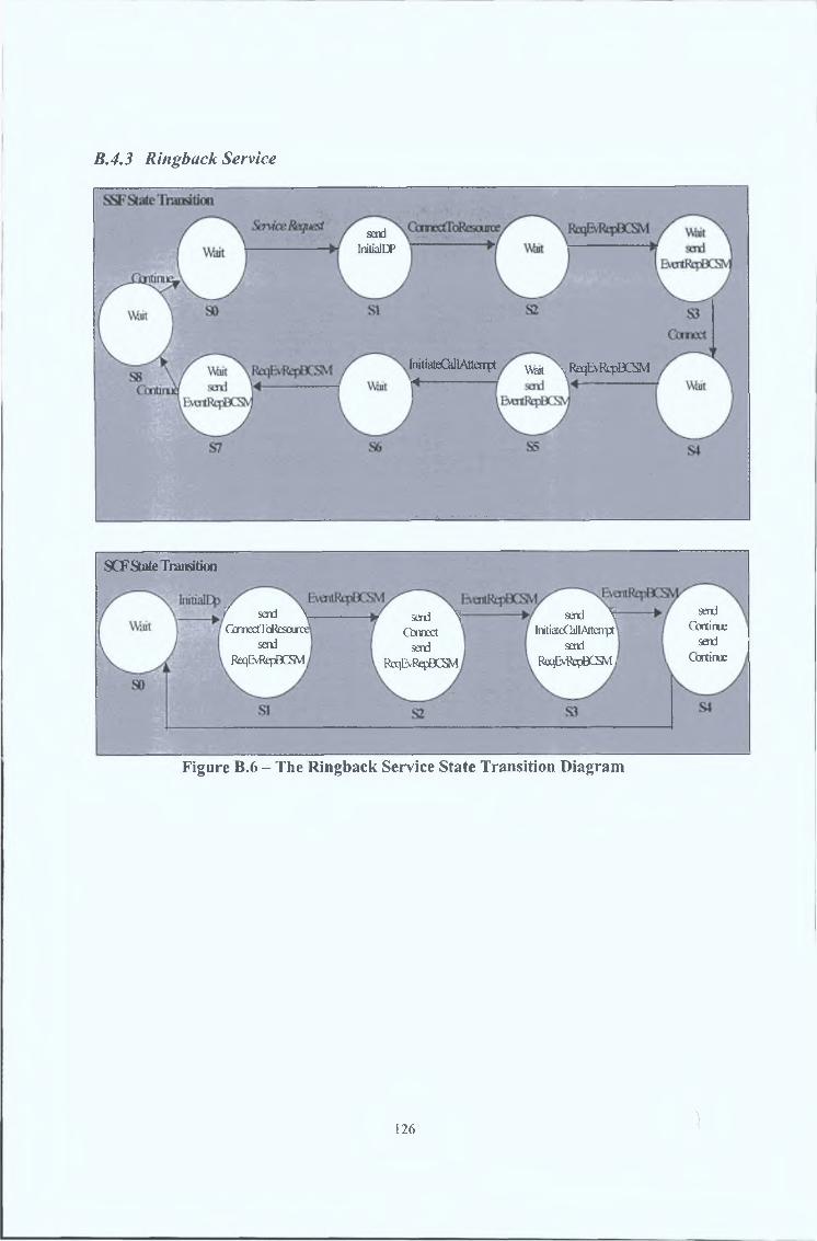
B.4.3 Ringback Service
sendInitialDP
initiateChllAtterrpt Wait \ ReqE\RfpBCSvl
SCF State Transition
sendContinue
sendContinue
/ send \ CbmectToResaixx
send ReqEvRepDCSVl
send \ InitiateGJlAttaipt
sendReqEvReptìCSM I
send ^ Cot meet
send ReqLMfcpBCSM
Figure B .6 - The R ingback Service State Transition D iagram
126 Ì

C. APPENDIX C: MARINER SYSTEM
C.l RAA
RAAInterfaœ
Tirnat)DemandOSuppigResourceAllocatorOdeadlineExpiredOsencfTokmAllocationOresouroeDötaOnotificationOlate_all(X_wamingO
___ iïKdTinHÛ.
_ _ _ _ _
startTimerOmodTimerO
Resource AllocatorsetOfferOgstOfifersOclearQfifersO
startAllocationODemand
setBidOmodBidOgetBidsOclearBidsO
> creates [>extends — -^invokes method • • •}> implements interfk^
Figure C .l - The RAA classes
The RAA functions as described in § 4.3.4. Figure C.l illustrates the RAA classes and
their relationships. Below are the class descriptions.
C .l A D em a n d
The Demand class maintains an array of all token requests by SSF and Service Type
received in a particular token allocation interval.
• setB\d(tokenRequest, ssf, serviceType) inserts a new tokenRequest into the array
position dictated by ssf and serviceType.
• modBid(tokenRequest, s s f serviceType) modifies a particular array entry.
127

• getBidsQ returns the token request array.
• clearBidsQ clears the array.
C.1,2 RAA
The RAA class contains the main() of the RAA. It also implements the RAAInterface
interface. It does the following:
• It instantiates the ResourceAllocator, Timer, Demand and Supply objects.
• It calls the startTimer(token_allocation_interval) method in the Timer object.
• For each resourcQ_data(resource_data) method call received, it extracts the SSF
token requests, and SCF capacities from resourcedata and calls the
Demand.setBid(tokenRequest, s s f serviceType) and the Supply.se\.Offex(capacity, scf)
respectively.
• When the notification (notification) method is called, it calculates the increased
tokenRequest from the notification data, and calls the Demand.modBid(tokenRequest,
s s f serviceType) method with the new tokenRequest.
• When the late_alloc_waming(/7erzoJ) is called, it calls the Timer.modTimer(-/?enc>d)
method, to decrease the timer by the period. In subsequent intervals, if no more
warnings are received, it will increase token_allocation_interval with increments o f 1
second by calling the same method.
• When the deadlineExpired() method is called, it calls the
ResourceAllocator.startAllocation() method.
• When the sendTokenAllocation(tokenallocation) method is called, it sends the
token_allocation to all the RMAs by calling the
RMAInterface.token_allocation(token_allocation) method.
C.1.3 RAAInterface
The RAAInterface is an interface class that allows the MARINER Information Flows
(See Appendix A) into the RAA. It has following methods:
128

v o id r e s o u r c e _ d a t a ( R e s o u r c e D a t a r e s o u r c e _ d a t a )
v o id l a t e _ a l l o c _ w a r n i n g ( i n t p e r io d )
v o id n o t i f ic a t io n (N o t i f ic a t io n n o t i f ic a t io n )
C.1.4 ResourceAllocator
The ResourceAllocator class implements the MARINER algorithm. When the
startAuction() method is called, it gets the SSF tokenRequests and SCF capacities by
calling the Demand.getBids() and Supply.getOffers() methods respectively. It then clears
the requests and capacities by calling the clear methods. The algorithm is then run,
resulting in a tokenAllocation. The ResourceAllocator then calls the
RAA.sendTokenAllocation(tokenAllocation) method.
C.1.5 Supply
The Supply class maintains an array of all resource capacity by SCF received in a
particular token allocation interval.
• setOffer(capacity, scf) inserts a new capacity into the array position dictated by scf.
• getOffers() returns the capacity array.
• clearOffers() clears the array.
C.1.6 Timer
The Timer class continuously countsdown an interval when the startTimer(z>*temz/)
method is called. Every time it completes the countdown, it calls the
RAA.deadlineExpired() method. When the modT\mQr(period) is called, it modifies the
countdown interval period.
129

C.2 RMA
> creates [>extends — *invokes method • • inplerrents interface
Figure C.2 - The RM A classes
The RMA functions as described in § 4.3.3. Figure C.2 illustrates the RMA classes and
their relationships. Below are the class descriptions.
C.1.7 Timer
The Timer class continuously countsdown an interval when the startTimer(z«/erva/)
method is called. Every time it completes the countdown, it calls the
RMA.deadlineExpired() method. When the modTimer(period) is called, it modifies the
countdown interval period.
C.1.8 RMA
The RMA class contains the main() method o f the RMA. It also implements the
RMAInterface interface. It does the following:
130

• It instantiates the Timer and RMA2SCF objects
• When the token allocation(token allocation) method is called, it calls the
RMA2SCF.sendTokenAllocation(/0&e«_<2//0az/zc>H) method.
• It calls the startTimer(interval) method in the Timer object.
• When the deadlineExpired method is called, it calls the
RMA2SCF.getResourceData(), the RMA2SCF.getNotifications() and the
RMA2SCF.getAcks methods.
• When the late_data_waming(/?erzW) is called, it calls the Timer.modTimer(-/?en0£/)
method, to decrease the timer by the period. In subsequent intervals, if no more
warnings are received, it will increase the interval with increments of 1 second by
calling the same method.
C.1.9 RMAInterface
The RMAInterface is an interface class that allows the MARINER Information Flows
(See Appendix A) into the RMA. It has following methods:
v o id t o k e n _ a l l o c a t i o n ( T o k e n A l l o c a t i o n t o k e n _ a l l o c a t i o n )
v o id l a t e _ d a t a _ w a r n i n g ( i n t p e r io d )
C.1.10 RMA2SCF
The RMA2SCF class is responsible for communication with the SCF. Whenever any
method is calld upon it, it calls the corresponding method on the SCF Scf2RMA
interface.
131