![Bridgeless Buck-Boost PFC Converter for Multistring LED Driver€¦ · boost converter as a universal PFC converter [6]. In order to address these issues, a buck-boost converter is](https://static.fdocuments.us/doc/165x107/5eaabf2a4ab79d1e774f9005/bridgeless-buck-boost-pfc-converter-for-multistring-led-driver-boost-converter-as.jpg)
A PFC Cuk Converter for BLDC Motor Drive with One Cycle Control · 2017-12-26 · Sensor less BLDC...
8
Page 58 A PFC Cuk Converter for BLDC Motor Drive with One Cycle Control Ganesh Reddy Katla Department of Electrical & Electronics Engineering, Anurag Group of Institutions; Medchal (Dt); Telangana - 500 088, India. G Anuroopa Department of Electrical & Electronics Engineering, Vaagdevi College of Engineering; Warangal (Dt); Telangana - 506005, India. Abstract: In this concept a bridgeless Cuk rectifier is used for Power factor correction (PFC) for a BLDC motor. Bridgeless Cuk converter has only two semiconductor switches in the current flowing path. During each interval of the switching cycle it result in less conduction losses and an improved thermal management compared to the conventional Cuk PFC rectifier. To achieve almost unity power factor and to reduce the input current stress, the topologies are designed to work in discontinuous conduction mode (DCM). The DCM has additional advantage such as zero-current turn-on in the power switches, zero current turn-offs in the output diode. The ac-dc conversion of electric power is usually required for the BLDCM drive; it causes many current harmonics and results in poor power factor at input ac mains. This concept deals with power factor correction of BLDCM with bridgeless Cuk converter. A three phase voltage source inverter is used as an electronic commutator to operate BLDCM. Keywords: Nonlinear Control, OCC (One Cycle Control), Conventional Control, Switch Variable. I. INTRODUCTION Brushless DC (BLDC) motors are preferred as small horsepower control motors due to their high efficiency, silent operation, compact form, reliability, and low maintenance. However, the problems are encountered in these motor for variable speed operation [1-3]. Over last decades continuing technology development in power semiconductors, microprocessors, adjustable speed drivers control schemes and permanent-magnet brushless electric motor production have been combined to enable reliable, cost-effective solution for a broad range of adjustable speed applications. Recent research has indicated that BLDC motor drives could become serious competitors to the induction motor for servo applications [4-6]. BLDC motor is an ideal motor for low-medium power applications because of its high efficiency, high torque to inertia ratio, low maintenance and wide range of speed control. It consists of three phase windings on the stator and permanent magnets on the rotor. Being an electronically commutated motor, the commutation losses in the BLDC motor are negligible BLDC motor when fed by an uncontrolled bridge rectifier with DC link capacitor results in highly distorted supply current which results in low PF (Power Factor) and high THD (Total Harmonic Distortion); hence various improved power quality AC-DC converters are used in these drives [7-8]. Solid-state ac–dc conversion of electric power is widely used in adjustable-speed drives (ASDs), switch-mode power supplies (SMPSs), uninterrupted power supplies (UPSs), and utility interface with nonconventional energy sources such as solar PV, etc., battery energy storage systems (BESSs), in process technology such as electroplating, welding units, etc., battery charging for electric vehicles, and power supplies for telecommunication systems, measurement and test equipment [9-10]. Conventionally, ac–dc converters, which are also called rectifiers, are developed using Cite this article as: Ganesh Reddy Katla & G Anuroopa, "A PFC Cuk Converter for BLDC Motor Drive with One Cycle Control", International Journal & Magazine of Engineering, Technology, Management and Research, Volume 4 Issue 11, 2017, Page 58-65.
Transcript of A PFC Cuk Converter for BLDC Motor Drive with One Cycle Control · 2017-12-26 · Sensor less BLDC...

Page 58
A PFC Cuk Converter for BLDC Motor Drive with One Cycle
Control
Ganesh Reddy Katla
Department of Electrical & Electronics Engineering,
Anurag Group of Institutions;
Medchal (Dt); Telangana - 500 088, India.
G Anuroopa
Department of Electrical & Electronics Engineering,
Vaagdevi College of Engineering;
Warangal (Dt); Telangana - 506005, India.
Abstract:
In this concept a bridgeless Cuk rectifier is used for
Power factor correction (PFC) for a BLDC motor.
Bridgeless Cuk converter has only two semiconductor
switches in the current flowing path. During each
interval of the switching cycle it result in less
conduction losses and an improved thermal
management compared to the conventional Cuk PFC
rectifier. To achieve almost unity power factor and to
reduce the input current stress, the topologies are
designed to work in discontinuous conduction mode
(DCM). The DCM has additional advantage such as
zero-current turn-on in the power switches, zero
current turn-offs in the output diode. The ac-dc
conversion of electric power is usually required for the
BLDCM drive; it causes many current harmonics and
results in poor power factor at input ac mains. This
concept deals with power factor correction of BLDCM
with bridgeless Cuk converter. A three phase voltage
source inverter is used as an electronic commutator to
operate BLDCM.
Keywords: Nonlinear Control, OCC (One Cycle
Control), Conventional Control, Switch Variable.
I. INTRODUCTION
Brushless DC (BLDC) motors are preferred as small
horsepower control motors due to their high efficiency,
silent operation, compact form, reliability, and low
maintenance. However, the problems are encountered in
these motor for variable speed operation [1-3]. Over last
decades continuing technology development in power
semiconductors, microprocessors, adjustable speed
drivers control schemes and permanent-magnet
brushless electric motor production have been combined
to enable reliable, cost-effective solution for a broad
range of adjustable speed applications. Recent research
has indicated that BLDC motor drives could become
serious competitors to the induction motor for servo
applications [4-6]. BLDC motor is an ideal motor for
low-medium power applications because of its high
efficiency, high torque to inertia ratio, low maintenance
and wide range of speed control. It consists of three
phase windings on the stator and permanent magnets on
the rotor. Being an electronically commutated motor, the
commutation losses in the BLDC motor are negligible
BLDC motor when fed by an uncontrolled bridge
rectifier with DC link capacitor results in highly
distorted supply current which results in low PF (Power
Factor) and high THD (Total Harmonic Distortion);
hence various improved power quality AC-DC
converters are used in these drives [7-8].
Solid-state ac–dc conversion of electric power is widely
used in adjustable-speed drives (ASDs), switch-mode
power supplies (SMPSs), uninterrupted power supplies
(UPSs), and utility interface with nonconventional
energy sources such as solar PV, etc., battery energy
storage systems (BESSs), in process technology such as
electroplating, welding units, etc., battery charging for
electric vehicles, and power supplies for
telecommunication systems, measurement and test
equipment [9-10]. Conventionally, ac–dc converters,
which are also called rectifiers, are developed using
Cite this article as: Ganesh Reddy Katla & G Anuroopa, "A PFC
Cuk Converter for BLDC Motor Drive with One Cycle Control",
International Journal & Magazine of Engineering, Technology,
Management and Research, Volume 4 Issue 11, 2017, Page 58-65.

Page 59
diodes and thyristors to provide controlled and
uncontrolled dc power with unidirectional and
bidirectional power flow. The proposed scheme for the
Sensor less BLDC motor drive fed by a ta based PFC
converter operating in DICM mode is shown in Fig. 1.
The front end Cuk DC-DC converter maintains the DC
link voltage to a set reference value. Switch of the Cuk
converter is to be operated at high switching frequency
for effective control and small size of components like
inductors. A sensor less approach is used to detect the
rotor position for electronic commutation A high
frequency MOSFET of suitable rating is used in the
front end converter for its high frequency operation
whereas an IGBT’s (Insulated Gate Bipolar Transistor)
are used in the VSI for low frequency operation.
Fig.1.Block diagram for Cuk converter fed BLDC
motor Drive.
The proposed scheme maintains high power factor and
low THD of the AC source current while controlling
rotor speed equal to the set reference speed. A voltage
follower approach is used for the control of DC-DC
converter operating in DICM. Applications, where over
a speed range the load on the motor varies, demand good
dynamic responses and a high speed control accuracy.
Automotive, electronic steering control, fuel pump
control, electric vehicle control and engine control are
good examples of these. In aerospace also there are a
number of applications. In order to use these motors
effectively at their optimal efficiency and in safe
operating zone they must be driven at their nominal
power requirement. Power electronic converters provide
the required solution to meet the demand of the desired
regulated electrical power for dynamic and efficient
operation of BLDC motor drives. Here, a BLDC motor
drive fed by a PFC Cuk converter with One Cycle
Control is proposed as in Fig. 2.
Fig.2. Proposed Cuk PFC with OCC Topology.
II. ONE CYCLE CONTROL
The "One Cycle Control" technique was developed as a
general pulse width modulator control method [1- 8]. It
is also known as the integration with reset technique
where the key element is the resettable integrator. The
One Cycle Controller is comprised of an integrator with
reset switch, a comparator, a flip-flop and a clock as
shown in Fig. 3. The clock triggers the SR flip flop to
turn ON the transistor with a switch function K (t) and
constant frequency fs given as:
(1)
The input signal x(t) is chopped by the converter switch
and given to the output node of the switch to form a
switched variable yet). The frequency and the pulse
width of the switched variable yet) is the same as
that of the switch function K(t) , while the envelope of
yet) is the same as that of the input signal x(t). The
corresponding waveforms are given in Fig. 4. When the
switch is turned on by a fixed frequency clock pulse,
voltage available across the switch variable is being
integrated. The integrator output is compared with the
control reference by using a comparator. When the
integrated value of the voltage becomes equal to the
control reference, the integration is immediately reset to
zero to prepare for the next cycle. Since the switched
variable always follows the control reference the output
voltage is independent of all input voltage variations.

Page 60
Fig.3. One Cycle Control.
Fig.4. One Cycle Controlled Switch Waveforms.
ONE CYCLE CONTROL OF CUK CONVERTER
Flow-Graph which is a nonlinear modelling technique,
can be used to study the OCC converters [10]. A
switching converter usually contains more than one
signal switch in its Flow-Graph. A Cuk converter,
contains four signal switches in its switching Flow-
Graph, two current switches and two voltage switches,
as shown in Fig. 5. Any signal switch can be selected for
One Cycle Control, current or voltage depending on the
application of the circuit. The One Cycle Control breaks
the Cuk converter into two second order systems, input
loop and output loop, on which the stability of the One
Cycle Controlled system depends. The output loop being
a linear system is always stable. The input loop is a
second order nonlinear system. The large-signal
dynamic analysis concludes that the One Cycle
Controlled system is not globally stable, but with proper
limitation of the Duty Ratio (below 70%), a global
stability can be attained. In the converging region the
One Cycle Control achieves zero steady-state error and
zero dynamic tracking error between the control
reference value and the average value of the switched
variable. The transients of the capacitor voltage and the
inductor current are not instantaneous. The One Cycle
Control takes advantage of the pulsed and nonlinear
nature and achieves the instant control over the average
value of the switched variable.
Simplified Voltage Control and One Cycle Control of
PFC Cuk Converter for BLDC Motor Drive
Fig. 5. The Signal Flow Graph of Cuk converter.
IV. OPERATION AND CONTROL OF BLDC
MOTOR The Cuk PFC converter topology has a
conventional diode bridge rectifier fed from AC mains
followed by the One Cycle Controlled Cuk converter,
an output voltage ripple filter and a three phase VSI to
drive the BLDC motor. The Cuk DC-DC converter gives
a controlled DC voltage by suitable conditioning of the

Page 61
uncontrolled DC output of DBR and the power factor is
controlled through the high frequency switching of the
Power Factor Correction switch [9]. The regulated DC
output voltage from the Cuk converter is decided by
its Duty Ratio (D) which in turn is controlled by the One
Cycle control. The switching frequency (fs) of the
converter is fixed by the switching device used, power
level, operating voltage and switching losses of the
device. The control technique requires a voltage sensor
for controlling the DC link voltage with a unity
power factor. For the control, the DC link voltage
(i.e. the converter output voltage) is sensed and
compared with the set reference DC link capacitor
voltage or Hall effect sensors are used to sense the rotor
position of BLDCM and converted to speed signal, this
motor speed is compared with a reference speed. This
error in speed is compared with the converter output
voltage and given to the integrator. The input current
reference is compared with speed error controller output.
The integrator and the speed error controller output are
given as inputs to the comparator followed by a flip flop
to produce the gating signals for the switch. The control
strategy is represented through a block diagram in Fig. 6.
Fig.6. Controller Block Diagram.
V. DESIGN OF A PFC CUK CONVERTER
The Cuk converter is designed for DCM operation. In
DCM, any one of the energy storing elements Li, Lo or
CI are allowed to operate in discontinuous mode. Here,
Lie is operated in DCM. The output voltage, Vde of Cuk
converter is given as:
(2)
Where D represents the duty ratio.
The instantaneous value of duty ratio, D(t) depends on
the input voltage appearing after DBR Vinet) and the
required DC link voltage, Vde.
The critical value of input inductor Lie is expressed as:
(3)
The value of input inductor has to be selected lower than
the value obtained for Vde max to work in
discontinuous
conduction mode.
The critical output side inductor is designed as:
(4)
The critical value of intermediate capacitance Cle is as:
(5)
The value of DC link capacitor is calculated by:
(6)
Where represents the permitted ripple in DC link voltage
which is taken as 4% Of Vdc.
VI. MATLAB/SIMULATION RESULTS
Matlab/Simulation model of with fixed speed as shown
in Fig.7.
Fig.7.Matlab/Simulation model of with fixed speed.
Page 62
A. PFC at Input Mains
The current and voltage waveforms at AC input mains
(Fig.8) for input of 130 V and its harmonic spectra
during steady state at 1000 rpm are shown. It is observed
that the current THD at AC mains remains less than 3%
(Fig.9).
Fig. 8. Power Factor at AC mains.
Fig.9. Input Current THD.
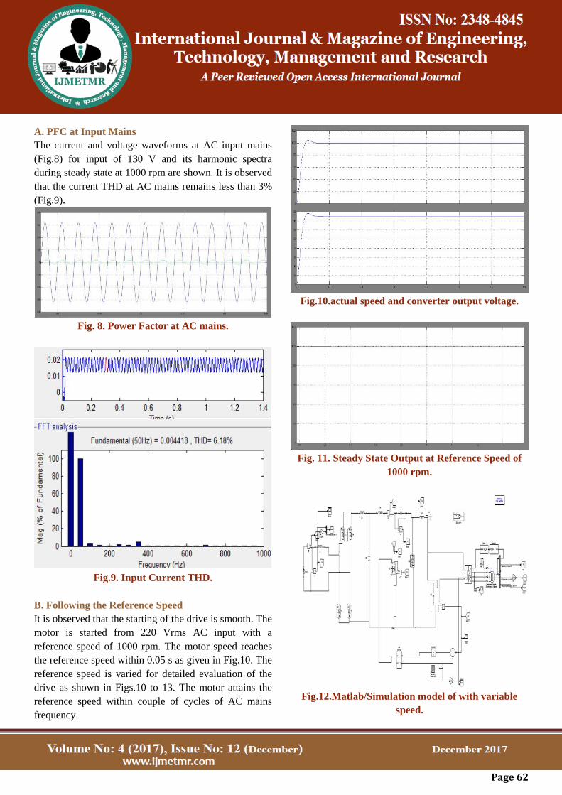
B. Following the Reference Speed
It is observed that the starting of the drive is smooth. The
motor is started from 220 Vrms AC input with a
reference speed of 1000 rpm. The motor speed reaches
the reference speed within 0.05 s as given in Fig.10. The
reference speed is varied for detailed evaluation of the
drive as shown in Figs.10 to 13. The motor attains the
reference speed within couple of cycles of AC mains
frequency.
Fig.10.actual speed and converter output voltage.
Fig. 11. Steady State Output at Reference Speed of
1000 rpm.
Fig.12.Matlab/Simulation model of with variable
speed.

Page 63
Fig. 13. BLDC Motor output at Varying Reference
Speed.
C. Performance During Varying Load
As the load increases more current is drawn by the
motor. In such conditions the control should be able to
maintain the motor speed at the desired reference speed.
A torque input of 2Nm is given to the motor with desired
speed of 2000 rpm at Is (Fig. 14). It is observed that the
rotor speed attains the reference speed by proper control
after a load variation is applied. The BLDC Motor stator
current and back EMF during loading is observed to be
as given in Figs. 14 to 17.
Fig.14. BLDC Motor Stator Current and Back EMF
during Loading.
Simplified Voltage Control and One Cycle Control of
PFC Cuk Converter for BLDC Motor Drive
Fig. 15. Performance Evaluation during Loading (2
Nm at 1sec.)
Fig.16.Matlab/Simulation model of with fixed speed
and PI Controller.
Fig.17. Input Current THD with PI Controller.

Page 64
VII. CONCLUSION
A OCC Cuk converter based PFC topology for a
PMBLDCM drive has been proposed and validated, The
performance of the drive has been found very well in the
wide range of input AC voltage, The simulation results
attained under various operating conditions illustrate that
the One Cycle Control gives robust performance and
faster dynamic response. Moreover, no PI tuning is
required. The One Cycle Controlled PFC Cuk converter
is observed to give the desired performance, i.e., fast
response and near unity power factor at AC mains.This
topology has been found suitable for the applications
involving speed control at constant torque load due to its
fast dynamic response. The concept of One Cycle
Control is straightforward and its implementation
circuits are general and simple, yet it provides excellent
control.
VIII. REFERENCES
[1] K. M. Smedley, "Control art of switching
converters," Ph.D. Thesis, California Institute of
Technology, Pasadena, 1990.
[2] K. M. Smedley, "One-Cycle Control of switching
converters," IEEE Trans. Power Electron. , vol. 10, no.
6, pp. 625-633, Nov. 1995.
[3] K. M. Smedley, "Control art of switching
converters," Ph.D. Thesis, California Institute of
Technology, Pasadena, 1990.
[4] A. Capel, G. Ferrante, D. O'Sullivan, and A.
Weinberg, "Application of the injected current model for
the dynamic analysis of the switching regulators with the
new concept of Lc3 modulator," in IEEE Power
Electronics Specialists conference, 1978 Record, pp.
135-147 (IEEE Publication 78ch1337-5 AES).
[5] C. W. Deisch, "Simple switching control method
changes power converter into a current source," in IEEE
Power Electronics Specialists Conference, 1978 Record,
pp. 300-306 (IEEE Publication 78ch 1337-5 AES).
[6] R. D. Middlebrook and S. Cuk, "Advances in
switched mode power conversion vols. I, 11, & Ill,"
TESLAco 1981 and 1983.
[7] R. Venkataramanan, A. Sabanovic, and S. Cuk,
"Sliding mode control of DC-to-DC converters," in Proc.
IECON '85. 1985 Int. Con! Industrial.
[8] Z. Ru, B. Zhang, W. Deng. "Feasibility Study on One
Cycle Control for PWM Switched Converters".
Proceedings of the 5th 35th Annual IEEE Power
Electronics Specialisers Conference: pp. 3359-3365,
2004.
[9] K. Smedley and Siobodan Cuk "Dynamics of One-
Cycle Controlled Cuk Converters", IEEE Transactions
on Power Electronics, Nov. 1995, Vol. 10, No. 6, P634-
639.
[10] K. M. Smedley, "Switching flow-graph nonlinear
modeling technique," IEEE Trans. Power Electron. , vol.
9, no. 4 pp. 405413, July 1994.
Author Details
Ganeshreddy Katla, received his M.Tech from Anurag
Group of Institutions in the year 2017 in Power
Electronics and electrical drives and B.Tech degree from
Vaagdevi Engineering College in the year 2014 in
electrical and electronics engineering.His area of interest
are Power Electronics and drives and Renewable Energy
Source. Published 1 international journal till date.

Page 65
G Anuroopa, received M.Tech from Vaagedevi College
of Engineering in Power electronics in the year 2017 and
B.Tech from Vaagdevi Engineering College in EEE in
the year 2014.Her area of interest is power electronics.