
Generic Frameworks for Interactive Personalized Interesting Pattern Discovery

An Architectural Pattern for Designing Component-Based Application Frameworks
David Parsons1, Awais Rashid2, Alexandru Telea3, Andreas Speck4
1Institute of Information and Mathematical Sciences, Massey University, Auckland 1310, New Zealand
2Computing Department, Lancaster University, Lancaster LA1 4YR, UK [email protected]
3Department of Mathematics and Computing Science, Eindhoven University of Technology, 5600 MB Eindhoven, The Netherlands
[email protected] 4Intershop Research, Intershop Tower, D-07740 Jena, Germany
[email protected] SUMMARY A widely used architecture for the development of software systems is the component based application framework. Such frameworks offer two mechanisms. First, they provide component integration and interoperability services which make it possible to extend the framework with various third-party components. Second, they provide mechanisms to customise the integrated components to the specific needs of applications to be built using the framework. This paper describes an architectural pattern for designing such frameworks so that the appropriate mix of fixed and flexible elements can be integrated into architectures that maximize scalability and extensibility. The pattern is illustrated by frameworks developed for three different application domains: electronic design automation, scientific visualisation and numerical simulation, and industrial control systems. KEY WORDS: framework, architectural pattern, component backbone, electronic design automation, simulation, visualisation, industrial control INTRODUCTION A central tenet of object technology adoption has been the promise of reuse, but this has proved difficult to deliver in practice. The reuse mechanisms and fine-grained abstractions offered by object-orientation are rarely sufficient for the development of large software systems. There is a necessary trade-off between reusability and tailorability [1] because the user’s requirements cannot be effectively anticipated. This leads to objects that are either too inflexible to customise or are not reusable without significant coding effort. This is fundamentally a problem relating to the development of an object in isolation from its deployment environment, because the object developer does not know anything about the context or semantics of its potential reuse. A partial solution to this problem has been the object-oriented framework, where the reuse context is constrained to a given domain. A framework can be defined as:
“a system that can be customised, specialised or extended to provide more specific, more appropriate or slightly different capabilities”. [2]
Frameworks are a helpful technology to support the reuse of proven software architectures and implementations and their use both reduces the cost of software and improves its quality [3]. A framework provides a basic system model for a particular application domain within which specialised applications can be developed. It consists of already coded pieces of software which are reused, the frozen spots, and the flexible elements, the hot spots, which allow the user
1
to adjust the framework to the needs of the concrete application [4]. Because a framework is targeted towards a specific problem domain, it does not suffer from the excessive abstraction that would render it too general for effective reuse. This is particularly true of application specific frameworks such as those used in hardware control systems [5] and scientific visualisation and simulation [6, 7, 8] where the application domain is narrow and focused. Unlike most class libraries, frameworks encapsulate control flows as well as object interfaces, thus modelling a system’s dynamic behaviour as well as its structure. In this paper we propose an architectural pattern for component-based frameworks, which we illustrate by presenting three frameworks developed for different application domains, each of which has a slightly different emphasis: First, electronic design automation, where runtime creation of new component types is necessary, second, scientific visualisation and numerical simulation, where there is a need to integrate a large number of disparate components, and finally industrial control systems, where integration of third party components is paramount. Object-oriented frameworks An object-oriented framework provides a context for reuse based on individual classes that extend and use an existing API. As a widely known example of an object-oriented framework, we consider the JUnit testing framework [9]. In this framework, the developer provides test cases that extend the TestCase class and override some polymorphic methods. User-defined classes can reuse the services of classes, such the Assert class, provided within the framework. Aggregation is supported through the assembly of test suites that consist of one or more test cases. The framework itself manages the lifecycle of test objects and provides a number of tools based on TestRunner classes for batch and interactive testing. The framework is code centric, relying largely on inheritance, and does not use metadata for configuration.
Object oriented frameworks such as JUnit provide an effective context for code reuse. However, they are limited in their scalability and extensibility due to the limitations of using individual objects as the elements of reuse. Objects are fine-grained code units that extend an existing set of application related operations but are otherwise loosely connected to, or even ignorant of, the host infrastructure. This makes it difficult to manage object lifecycles and metadata via the framework. An object-oriented framework is thus a code-centric construct that provides little flexibility for the management of objects plugged into it. It can work well for a well-bounded domain with predictable scalability, like unit testing, graphical user interfaces (GUIs) [10], or 3D graphics [11]. Moreover, practice has shown that pure object-oriented frameworks are limited even for a relatively narrow and well-defined application domain such as GUIs [12]. The main reason is a lack of object management services, such as GUI widget creation, object serialization, persistency, and control coding services to express how widgets interact with each other. On the one hand, the above mentioned loose (or even inexistent) connection of object-oriented frameworks with the host infrastructure makes such frameworks very portable across various operating systems and hardware platforms [10, 11]. On the other hand, however, this loose coupling causes the lack of desired object management services, which often need host infrastructure services. Object-oriented frameworks alone will not easily scale to cover several, potentially loosely related domains, or provide more flexible services over and above object instantiation and method calls. Therefore we must look to additional mechanisms to provide such support. Components and frameworks Component based development has been used to provide a more flexible model of reuse that overcomes many of the limitations of the object-oriented model. Unlike fine grained objects, components provide coarse grained units of reuse which publish both a client contract interface for application related operations and a technical contract interface that enables them to be
2
plugged into a sophisticated infrastructure. This infrastructure provides the framework for the component’s environment, an indispensable part of most component architectures.
A key feature of a component environment is the role of metadata. A component’s technical contract includes both callback-like mechanisms that enable its lifecycle to be managed by a separate framework infrastructure, and implicit assumptions about metadata that enable the component to be configured and customised after deployment without any modification to the component itself. Metadata, whether provided in code, as in the BeanInfo classes of the JavaBeans specification [14], or in some other form such as properties files or XML deployment descriptors, enables a degree of reflection [15] that makes components adaptable to new environments. The Qt GUI toolkit [12, 13] is a good example of how some of the limitations of object oriented frameworks can be overcome by combining object orientation, in the form of C++ class libraries, with metadata that extends C++ with a signal-slot mechanism, essentially a dataflow construct.
The framework features described above are well illustrated by the Enterprise Java Beans (EJB) Specification [16], a widely used component based framework, which is implemented by Java application servers from many vendors. EJB provides an environment for distributed components that may be persistent (entity beans), service oriented (session beans) or asynchronous (message beans). EJBs must implement both a client contract and a technical contract, enabling the framework to delegate business operations and manage component lifecycles. Extensive use of XML based metadata increases the configuration flexibility of the framework and enables reuse of the same components into different application contexts. Very generic frameworks such as these provide the foundation for more specific frameworks. For example, EJBs are used as the basis for IBM Business Rules Beans [17], which are a more application-specific framework than the EJB architecture alone. Such approaches are the basis for the architectural pattern explored in this paper, whereby a framework backbone is customised by basic components and is open to extensibility by additional components to enable the building of an application. In the context of the IBM Business Rules Beans, the EJB container is the framework backbone, the rules beans are the basic components and the application developer's specific rules are the additional components. Component-based frameworks help in addressing integration and interoperability issues during component-based development. They also serve as larger units of reuse by allowing applications to customise them to suit their specific needs. The framework integrates and ensures proper interleaving and interaction of the various components initially forming part of the framework. It also provides facilities for future extensions with components developed in-house or obtained from a third party. The framework enforces policies for the tasks to be performed by the various components under its control. This allows partial enforcement of architectural principles [18]. In summary, component-based frameworks extend the notion of a framework to component-based development and provide: • Component integration services which make it easy to add third-party components to the
framework’s backbone, • Component interoperability services which enable components from multiple sources to
communicate via the framework, • Customisation mechanisms for adapting the integrated components to the specific needs of
applications to be built using the framework, • Metadata configuration facilities, used to maximise the reusability of component code
without the need for component reprogramming, • Specification and instantiation protocols for component instances, • A common model specification of commonly understood types, • Connectors to enable inter-component data communication via the framework’s backbone,
and
3

• Common services, such as persistence, transactions, security and reflection. Issues in component-based development The drive to use components to construct systems stems from a ‘parts’ philosophy, which promises instant productivity gains, reduced time to market and lower development costs due to higher reuse potential. However, component-based development poses several risks that can significantly increase the development effort for a component-based application. Key risk factors are the complexity of the component environment, the genericity of that environment, the level of metadata configuration available and the range of components that may be required to be integrated into the system, particularly where there will be a mix of components developed in-house and others acquired from third parties. In such systems component evolution and a lack of standards can make it difficult to facilitate the concurrent use of components implemented by different vendors using different component technologies. Components built using different technologies employ different architectures, making their integration a difficult task. They may have different data, control, and/or event models and be programmed in different languages, to cite only a few of the common problems. Components developed by one vendor are often not designed to interoperate with products from other vendors [19] because they offer proprietary interfaces or follow different component technologies. Even if the same component technology is employed, their behaviour can significantly vary. Practical experience developing the Aesop system [20] showed that as few as four multiple vendor products can prove to be too many in terms of integration and interoperability problems. In this system, the four products being integrated, OBST, InterViews, SoftBench and MIG, had inherent architectural mismatches. Although three of them were event-based, each had different event semantics. Also, each product assumed that it was the sole owner of the event queue. In the case of object oriented components, generic component integration solutions such as, for example, the Class Adapter pattern [10] are only of limited use. Indeed, the Class Adapter becomes cumbersome when more than two component class hierarchies are to be integrated, and also assumes that both component models allow multiple inheritance, which is often not the case [7, 11, 13].
One of the commonly employed solutions to integration and interoperability problems is the development of wrappers and glue code to tailor a component to exhibit behaviour and/or interfaces compatible with the others. However, these wrappers need to be maintained during system evolution and extension. Such maintenance problems can not only significantly increase the development effort required but can also adversely affect the scalability and extensibility of the component-based application. A good example of this is the VTK visualisation component library [7] which offers Java, Tcl, and Python language wrappers to allow its over 500 components coded in C++ to be dynamically managed from third-party applications. Even though VTK uses a sophisticated method to generate these wrappers automatically, thus minimizing wrapper development time, practice from VTK’s eight year history has shown that these wrappers are seldom ready-to-use without extra application-dependent manual tailoring. Since components must work within the context of some kind of framework, resolving these kinds of issues is the responsibility of the framework developer. However, this is no easy task. Components have much greater dependencies on their environment than ordinary objects, as illustrated by our list of required services. Consequently, frameworks can be very brittle. Poor initial design of a framework can mean complex maintenance, where required changes to the infrastructure break tightly coupled components. We can see, for example, that major changes to the Enterprise Java Beans Specification between versions 1.0, 1.1 and 2.0 effectively rendered existing persistent components obsolete as a result of each change, and the proposed EJB 3.0 standard will once again be incompatible with existing deployments. An identical situation occurred four times in the eight year development of the VTK framework between 1996 and 2004, with the release of versions 2.4, 3.1, 4.2, and 4.4. Given these risks, an appropriate
4
development approach is required that maximizes the chances of building an effective framework from the earlier iterations. The aim of this paper is to present an architectural pattern that can assist the framework developer in tackling the complexities of this task.
Many framework design patterns and development processes have been documented, typically reverse engineering the common framework architecture from a number of conventionally built applications within a given domain [21]. However, a reverse engineering approach to developing component-based frameworks is not feasible. The framework not only needs to address integration and interoperability problems for the components that initially form part of the framework, but it also needs to take into account integration and interoperability issues that might arise due to future extensions of the framework with in-house or third party components. The architectural pattern described in this paper for designing component-based frameworks is based on the forward engineering approach. An analysis of user requirements is seen as an essential aspect of the framework designer’s task. The users of a framework are categorised into a number of roles, each of which needs to be provided with an appropriate component level interface, metadata options and support tools. The union of these role requirements is seen as the interface specification that the framework designer must provide. WHITE AND BLACK BOX FRAMEWORKS The flexible elements of a component-based framework allow it to be customised for an application in a fashion similar to object-oriented frameworks. From this point onwards we will refer to these flexible elements as the hot spots in order to maintain consistency with the terminology for object-oriented frameworks. Based on customisation characteristics, object-oriented frameworks fall into two main categories, white box frameworks and black box frameworks.
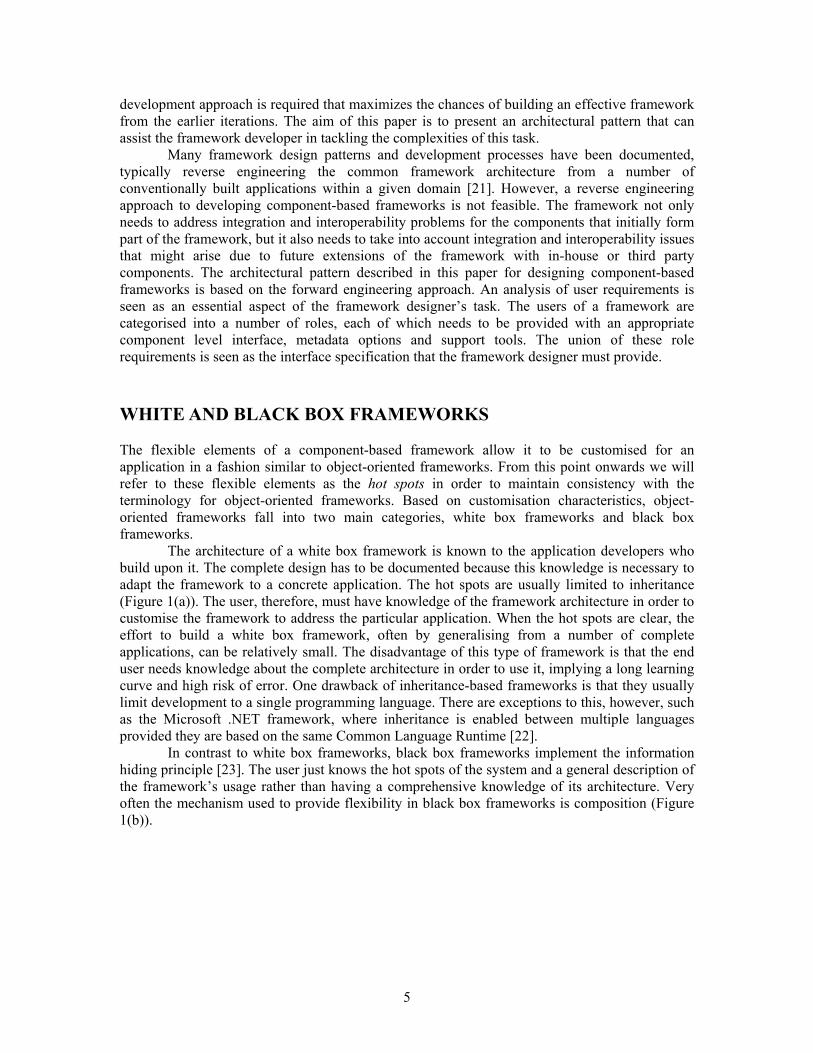
The architecture of a white box framework is known to the application developers who build upon it. The complete design has to be documented because this knowledge is necessary to adapt the framework to a concrete application. The hot spots are usually limited to inheritance (Figure 1(a)). The user, therefore, must have knowledge of the framework architecture in order to customise the framework to address the particular application. When the hot spots are clear, the effort to build a white box framework, often by generalising from a number of complete applications, can be relatively small. The disadvantage of this type of framework is that the end user needs knowledge about the complete architecture in order to use it, implying a long learning curve and high risk of error. One drawback of inheritance-based frameworks is that they usually limit development to a single programming language. There are exceptions to this, however, such as the Microsoft .NET framework, where inheritance is enabled between multiple languages provided they are based on the same Common Language Runtime [22]. In contrast to white box frameworks, black box frameworks implement the information hiding principle [23]. The user just knows the hot spots of the system and a general description of the framework’s usage rather than having a comprehensive knowledge of its architecture. Very often the mechanism used to provide flexibility in black box frameworks is composition (Figure 1(b)).
5

Frozen Spot Classes
Frozen SpotClasses
Hook Inheritance
Hook
Composition
White Box Black Box Application Application
Hot Spot Hot Spot
(a) (b)
Fig. 1: Hot spots in object-oriented frameworks: (a) the white box approach (b) the black box approach
Using a black box framework is easy because only knowledge about the flexible elements and the basic characteristics of the system is required. Black box frameworks, however, are harder to build than white box frameworks. It is more common to find the black box approach in application specific frameworks. Examples include the frameworks encountered in systems for controlling machinery [5, 24] where software components tend to mirror hardware components that have predictable types and strong design constraints imposed by the application domain. This approach is more problematic for more generic frameworks where it is harder to anticipate the types (and thus the behaviour) of the components that might be required. In practice there are few pure white or black box frameworks. In most cases, some hot spots are developed using a white box approach while others use the black box approach, an approach sometimes called grey box. In the process of framework implementation white box elements can be refined to black box hot spots, and frameworks tend to mature by this process, beginning as white box frameworks and evolving to black box frameworks.
In contrast with their object-oriented peers, component-based frameworks rarely use implementation inheritance as a customisation approach [18]. Quite often the customisation approach is based on composition. Consequently, a component-based framework is usually a black box framework. This can also be attributed to the black box nature of the components constituting the framework. Component-based frameworks offer greater flexibility and extensibility by allowing dynamic insertion of component instances at run-time. They can be extended with new components, used standalone, used in co-operation with other components or component-based frameworks or used as part of a higher-order component-based framework regulating the interactions of the lower-order frameworks [18].
Such flexibility can, however, only be achieved through a scalable and extensible framework design. Component-based frameworks pose a greater challenge as not only is the initial design important but also future extensions to the framework have to be taken into account. A COMPONENT-BASED FRAMEWORK PATTERN The systems development lifecycle of a framework is generally assumed to be a reverse engineered solution similar to pattern mining, whereby three or more domain specific solutions are developed and used to factor out the common framework [21]. Once this framework is
6

available it can be used to forward engineer further solutions within the same domain. In the case of component-based frameworks a reverse engineering approach might provide integration and interoperability for initial components in the framework. It cannot, however, anticipate future extensions to the framework effectively, hence compromising its extensibility. Forward engineering of frameworks, in general, and component-based frameworks, in particular, is a major challenge. The requirements of the framework user need to be clearly anticipated. The ease of extensibility promised by component-based systems implies that component-based frameworks need to be extensible with third party components without significant effort. Scalability is also important for the solution to be practically usable. It is, therefore, quite hard to build a component-based framework, though some such frameworks exist, including OpenDoc implementations [25], the BlackBox Component Framework (BCF) [26] and Portos [27].
Design patterns [10] express proven techniques making it possible to reuse successful designs and provide a common vocabulary to share design descriptions. Architectural patterns [28, 29] cover a wider realm, specifying system-wide structural properties for an application, and impacting on subsystem architecture. Our aim is to propose a generic architectural pattern for component-based frameworks. The pattern takes a forward engineering approach to framework design and is based on categorising the framework users into a number of roles, each of which needs to be provided with an appropriate component level interface. An analysis of the requirements of the various roles is, therefore, an essential part of the framework designer’s task as the union of these requirements is the interface specification that they must provide. The framework design is based on highly cohesive but loosely coupled components managed by a central framework backbone. Components can be developed independently of each other and are exchangeable, providing a high degree of flexibility. The architectural pattern is shown in Figure 2, and is in some ways similar to a layered architecture [28]. However, our view of the framework is that it follows a nuclear design, whereby there is a central core of functionality, the backbone, which supports additional components. Unlike a traditional layered architecture, where each layer can be seen to be of equal importance, and can in many cases be swapped out for an equivalent layer, the framework backbone is the core part of this pattern. This backbone, which includes metadata and a connector architecture, cannot be swapped out and replaced by another equivalent layer since it provides the core functionality of the systems that are built upon it. However, other elements of the pattern, such as the basic and additional components, can be swapped in and out and be replaced by other components. As well as having some similarities with a layered architecture, the framework design has some features in common with software bus architectures such as POLYLITH [30]. However, whereas this framework includes an element of message passing it is application specific rather then heterogeneous, and whilst it may be partially distributed this is not a core feature of the pattern. We may also make the distinction that whereas a key objective of a software bus is to decouple components, the framework architecture described here emphasises appropriate ways of coupling closely related components together. In addition, the framework has many features that are not generally associated with a software bus, including component-oriented metadata, component classification and customisable component hotspots.
7

Application (canonical / customised)
Legend
Framework Backbone
Metadata
Connector Architecture
AC
BC
BC BC
BC
BC
AC
Customises (implies uses)
Uses
Additional Component
Component-only customisable hot spot Hot spot
Basic Component
Backbone Boundary
AC
AC
AC BC
AC
Figure 2: The framework architectural pattern The proposed pattern has three core elements and requires three supporting elements. The core elements are the framework backbone, basic components and additional components. The supporting elements are metadata, a connector architecture and a canonical application.
The backbone is the basic, core element. Its design strongly depends on the requirements of the target application domain. It mainly provides communication, data exchange, synchronisation mechanisms and hot spots for plugging-in components. Basic components encapsulate the core functionality of the framework. They use the backbone through the component-only-customisable hot spots for data exchange and communication. Integration and interoperability support should be encapsulated in the backbone, alleviating the need for additional wrappers and glue code to adapt a component to the specific context. The connector layer is seen as a responsibility of the backbone rather than an orthogonal peer-to-peer communication mechanism. The framework backbone and the basic components are mandatory for a complete framework, as indeed is a canonical application. Applications can use and/or customise the basic and additional components but not the backbone, as the latter should preserve the invariants of the modelled domain and the integration and interoperability services in place. Additional components can, however, be added to adapt the framework to meet additional requirements. They may interact with both the basic components and with the backbone that calls back on their
8

services. This allows seamless extension of the framework with various third party components. It is important that hot spots are provided to support the combinations of component interactions indicated in Figure 2, namely that both basic and additional components can customise the backbone and that additional components can both use and customise basic components.
The modular design proposed by our framework pattern also supports the reuse of the backbone and the components in other contexts. It should be noted that the framework diagram in Figure 2 is not meant to be prescriptive, rather it provides a summary of the framework elements and the core set of component interrelationships. A given framework may not use all possible relationships, and may also aggregate relationships, so that, for example, a basic component may customise another basic component, and a custom component may customise another custom component. The three case studies that conclude this paper will contrast different aspects of these relationships, which will vary from domain to domain. THE FRAMEWORK DEVELOPMENT PROCESS In order to build a component-based framework based on the design pattern described above, we propose a methodology based on the four steps shown in Figure 3.
Application domainand role analysis
Backbonedevelopment
Basic ComponentsDevelopment
Additional ComponentsDevelopment
1 2
34
Iterative feedback
Figure 3: The Framework Development Process First, the application domain to be addressed by the framework needs to be identified. This should be followed by an analysis of the various developer/user roles. The developers/users are classified into four possible roles; framework developer, component developer, application developer and end user.
Figure 4 shows these various roles; the solid arrows indicate the actions involving each role. The framework developer builds the framework backbone. The component developer builds new components and integrates them into the framework. The application developer customises these components to produce a custom application expected by the end user. Consider, as an example, a graphical user interface (GUI) framework built by the framework developer, extended by component developers with add-on GUI components and used by application developers to build applications for end users. Software reuse appears in two places. First, component developers can reuse code via constructs of the component development language such as inheritance or templates to build new components. Second, the application developer employs the framework’s specific super language, or meta-language, mechanisms to reuse components when building applications or new components [31]. Meta language mechanisms are more effective and
9

flexible than development language coding mechanisms, since they are designed for a specific application domain.
Build
s
Uses
Add
s
Use
s
Bui
lds
Use
s
FrameworkDeveloper
ComponentDeveloper
ApplicationDeveloper
EndUser
Frameworkbackbone Components Application
Figure 4: Various developer and user roles in a component-based framework
The dashed block arrows in Figure 4 indicate that the presented roles may be assumed by the same people. For example, although the framework developer is mainly responsible for building the framework, they may also be the first component developer. Similarly the component developers, application developers and the end users could be the same people. The framework developer’s core challenge is to provide tools for all roles, which are likely to include component building tools for the component developers, application assembly tools for application developers and possibly command and control interfaces for end users. Even though framework developers and end users may (and should be able to) perform their specific tasks independently, the framework developer must implement all the mechanisms for all of these roles, such that each role gets the most suitable tools. This requirement is similar to that expressed by the EJB specification [16] which highlights the need for tool provision for the four application oriented roles in EJB development; component provider, application assembler, deployer and administrator. In addition to providing a framework satisfying the needs of all roles separately, framework developers must provide mechanisms to allow an easy role transition, since the same person may switch roles frequently. For example, an individual may create components as a component developer, then assemble them into a test application as an application developer, and finally experiment with the application as an end user. This scenario occurs in Microsoft’s .NET framework, where the interplay of automatic code generation mechanisms and visual, GUI-based code representations, minimizes the difference between component and application developer roles, though it is not completely eliminated. From the requirements we have outlined we believe there is a need to classify users into various roles and to clearly define the requirements for these roles and their mutual interactions. The union of these requirements provides the interface specification for the framework developer. This is a crucial phase in the framework development process, as a correct definition of roles and requirements strongly influences all the following steps [32].
10
Backbone development The framework backbone is designed and implemented here by the framework developer as a logical outcome of the requirements detected in the previous phase. Various integration and interoperability services based on the analysis phase are also introduced into the backbone during this phase. Providing the right flexibility and fulfilment of users’ requirements in the backbone, inferred from the role analysis, differentiates a successful framework from a rigid and inadequate one.
Fully compiled Fully interpreted
Flexibility
Implementation Complexity
Run-time Performance
High
High
High
Low
Low
Low
Hybrid Approaches
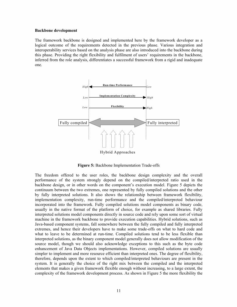
Figure 5: Backbone Implementation Trade-offs
The freedom offered to the user roles, the backbone design complexity and the overall performance of the system strongly depend on the compiled/interpreted ratio used in the backbone design, or in other words on the component’s execution model. Figure 5 depicts the continuum between the two extremes, one represented by fully compiled solutions and the other by fully interpreted solutions. It also shows the relationship between framework flexibility, implementation complexity, run-time performance and the compiled/interpreted behaviour incorporated into the framework. Fully compiled solutions model components as binary code, usually in the native format of the platform of choice, for example as shared libraries. Fully interpreted solutions model components directly in source code and rely upon some sort of virtual machine in the framework backbone to provide execution capabilities. Hybrid solutions, such as Java-based component systems, fall somewhere between the fully compiled and fully interpreted extremes, and hence their developers have to make some trade-offs on what to hard code and what to leave to be determined at run-time. Compiled solutions tend to be less flexible than interpreted solutions, as the binary component model generally does not allow modification of the source model, though we should also acknowledge exceptions to this such as the byte code enhancement of Java Data Objects implementations. However, compiled solutions are usually simpler to implement and more resource efficient than interpreted ones. The degree of flexibility, therefore, depends upon the extent to which compiled/interpreted behaviours are present in the system. It is generally the choice of the right mix between the compiled and the interpreted elements that makes a given framework flexible enough without increasing, to a large extent, the complexity of the framework development process. As shown in Figure 5 the more flexibility the
11
framework developer wants to provide, the more complex their task will be, since a more complex machinery has to be set up to cope with the run-time interpreted decisions, and the final system will probably be slower. Striking the right balance between the compiled and interpreted functionality is what makes a framework successful. Backbone development checklist The backbone developer can infer a number of tasks from the pattern. In particular they must identify the infrastructure services required of the backbone. These fall under the headings of required services and optional services, which are application dependent. The required services are; a connector architecture for plugging in components, a messaging element to the connectors and a metadata format that configures the backbone and connectors. Optional services will vary from framework to framework, but features such as distribution, security, transactions and persistence are commonly provided.
The most important architectural decision to be made is the degree of interpretation in the framework. In general, the higher the level of interpretation required, the greater need there will be for metadata. This metadata may range anywhere between code, similar to the BeanInfo classes of the JavaBeans specification, to text based configuration, such as property files or XML files. Often a mix of the two is present. For example the Qt GUI framework allows configuration via compiled languages such as C and C++, interpreted languages such as Python and resource files [13]. Basic components development The basic components and their hot spots are now developed, in conformance with the component interface offered by the existing backbone. This conformance should not be a constraint to the component developer, as these interfaces were inferred directly from the users’ requirements in the first phase. The analysis should focus on component requirements, which are serviced by the backbone. Basic component checklist The basic component developer can infer from the pattern that they must build components that conform to the connector specification of the backbone, provide one or more hotspots for customisation, provide an appropriate ‘using’ interface and provide appropriate metadata interaction.
The nature of the basic components will be largely determined by the nature of the backbone. For example, if the backbone hot spots use inheritance, then the basic components will be subclasses. Alternatively if interfaces, templates or aggregations are used, then the basic components will conform to this model. The set of basic components must also provide enough functionality to support the canonical application for the framework. The question of which is the best form of hot spot implementation, choosing for example between inheritance and templates is, we believe, an implementation-level issue, all these forms providing essentially the same services, freedom, and efficiency to the developer. Additional components development Finally, component developers or application developers may create an open set of custom components which directly plug into the existing framework and may or may not use the basic components. The only constraint is that additional components respect the backbone’s interfaces. Additional component checklist The additional component developer can infer from the pattern that they must build components that conform to the connector specification of the backbone and also conform to the extension
12
and ‘using’ specifications of the basic components. Their components must also provide the same hot spot interfaces as basic components and be able to plug into the ‘using’ interface of basic components. They must also provide appropriate metadata interaction. An iterative process The development phases described in this section do not have the strict task boundaries of the waterfall model [33]. As in other iterative OO software development processes [34, 35], the borders between the phases are weak and designers may work in two phases on different components at the same time. However a careful requirements analysis in phase 1 will yield a stable framework, localising most redesign to phases 3 and 4. Thus we infer that an iterative process is required to build the initial framework, and that this iterative process must include all phases of the framework, including a test driver that takes the role of additional components. In other words, successful framework development requires that a canonical application be built that acts as an integration test for the framework. We regard this as an essential part of the executable architecture that should result from the elaboration phase of an iterative process [35]. Additionally, a framework should be shipped with a working application in place that is open to end user customization. Examples of this type of framework can be seen in commercial commerce and portal servers such as BEA WebLogic Portal [36] and IBM Websphere Commerce Portal [37], where the framework includes a complete running application Similarly, we have seen that the lack of shipping such an application, combined with several versions released in a row, signalled the immaturity of a given framework. Such was the case of the frameworks described in references 7 and 38. FRAMEWORKS BASED ON THE PATTERN This section presents three frameworks based on the pattern described in the previous section. The discussion explores the key features of the designs resulting from the pattern approach. ELECTRONIC DESIGN AUTOMATION FRAMEWORK We have discussed in previous sections that frameworks can exist at various levels of specialisation, ranging from the highly generic (e.g. Enterprise Java Beans) through domain specific frameworks (e.g. IBM San Francisco [39]) to application specific frameworks. In the latter case, the framework provides highly focussed services for component building within a specific application, which may have very specialised requirements. Our first example system is an application framework taken from the domain of Electronic Design Automation (EDA). The framework itself is a schematic capture system, built in C++, that enables the graphical representation of electronic circuit designs, while the sample application that uses the framework is a code generator that converts a circuit representation into a hardware description language. In this case, the language is VHSIC Hardware Description Language Analogue and Mixed Signal, generally known as VHDL-AMS. EDA backbone features It is important for a schematic capture system to allow new component types to be modelled by the designer. Traditionally in this kind of design tool the definition of new components has been achieved through aggregation, namely building larger components from smaller ones, but languages such as VHDL-AMS also allow behavioural modelling, where components can be described in terms of behaviour specified by code. Circuit designers using a graphical schematic capture system therefore need a facility for describing new components both in terms of their electronic properties, such as whether they are analogue or digital, and their visual representation, using tools within the GUI. Ideally, the description of new components should be possible at run
13

time. To support these features the backbone design leans heavily towards the interpreted rather than the compiled approach. It has been built on the assumption that new components can be instantiated by implementing a standard interface, with instances populated by properties that are readable from metadata at run time. EDA connector architecture The connector architecture used in this system is based on an acyclic directed graph, the nodes of which can accept a component plug-in that conforms to a standard interface. This is an application specific implementation that mirrors the requirements of electronic circuit analysis. The backbone must be responsible for managing the underlying circuit representation that encapsulates component connectivity and interaction. The graph is a data structural representation of the physical circuit that is being modelled. The connector specification for components, which defines the plug in hot spots, requires that data be provided to enable adding visual images to the library and contain appropriate syntax for code generation. EDA messaging element Messaging in the system is primarily about running the core algorithms for circuit analysis and code generation. Messaging essentially takes the form of a broadcast mechanism. As the graph of components is traversed, each responds polymorphically to the same set of method calls to construct information to the overall circuit representation. EDA metadata format The metadata format is based on properties files that enable the population of a standard component interface implementation with component specific data. The metadata used in the system encapsulates a number of different features of components, including
• Expected connection parameters (this is part of the backbone connector contract) • Visual representation data (captured from a component developer tool that enables new
component representations to be drawn) • Electronic type information for components (digital, analogue, input, output etc.)
Since the metadata protocol enables component properties to be changed and extended dynamically, component instances can be provided with new behaviours at run time. EDA component definition, customisation and use The basic components in the system include the fundamental set of electronic components that designers expect to be available in a component library. These include, for example, various types of digital gates and standard analogue components such as resistors and capacitors. Additional components are provided at run time by the user of the system, who can describe the characteristics of the components via a visual object building interface that provides a context for behavioural modelling. All components are described using a single C++ Component class rather than a classification hierarchy of types, thus the need to compile new components is avoided since new ‘types’ are simply new collections of configuration data. This might be seen as a data-centric variation on the State and Strategy patterns [10] whereby behaviour is changed by switching between encapsulated objects. Component instances are created using a code mechanism similar to a virtual constructor idiom [40]. These in turn can be seen as a C++ specific application of the Factory Method pattern [10] that is commonly used to instantiate components in frameworks. This approach to dynamic component building is a technique that would be difficult to achieve in a more generic framework where component behaviour is not tightly constrained, and where the meaning of metadata could not be so easily defined. However, in an application specific framework like this it is a powerful tool. Development of additional electronic component models is achieved by user dialogues that gather the necessary component
14
identification, representation and configuration data and write it to properties files. Since this mechanism is available both at compile time and run time, so is therefore not exclusively a run time feature, new components can be created by both the component developer and the application developer. Mapping the EDA system to the framework process and model Referring to our development model, we can identify the phases of the development process as: 1. Identification of the requirements for a schematic capture system within the domain of EDA
that the framework is to address 2. Development of the basic library of electronic components and services 3. Development of additional electronic component models 4. Development of a canonical application, in this case a VHDL-AMS code generator. Other
applications that might be built on this framework could generate code in other hardware description languages or provide simulation outputs.
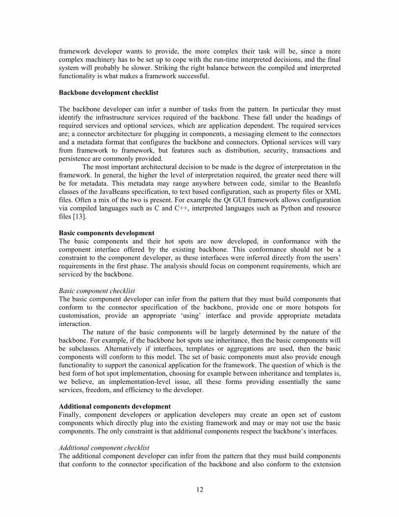
Figure 6 shows how this framework maps to the architectural pattern described in Figure 2.
VHDL-AMS Code Generator Application
Custom component
Analogue Component
Component interface
Aggregate component Digital
Component
Schematic Capture
Backbone
Properties Files
Circuit traversal Connector
Architecture – Acyclic
Directed Graph
User SCI
Component connection
Figure 6: An instantiation of the pattern for the EDA framework EDA canonical application description The sample application built on this framework is a code generator for VHDL-AMS. For a component in the schematic capture system to contribute to code generation, it requires additional metadata for its VHDL-AMS description. This customisation of the framework uses the same mechanism as the basic framework, namely properties files generated by input tools. Edit windows are provided for this purpose, containing a code skeleton for the component within which the VHDL-AMS entity and architecture descriptions can be written. The entity description provides the external interface of the model, comprising its parameter list for invoking the component with names, data types and default values, and the names and signal types of its
15
external connections. The architecture provides the internal behavioural description of the component with the necessary equations and conditional statements.
For components with digital characteristics it is sometimes important that multiple models are provided, one for purely digital modelling and others for combinations of digital and analogue inputs and outputs. Therefore the application makes a number of assumptions about the models that should exist for gates.
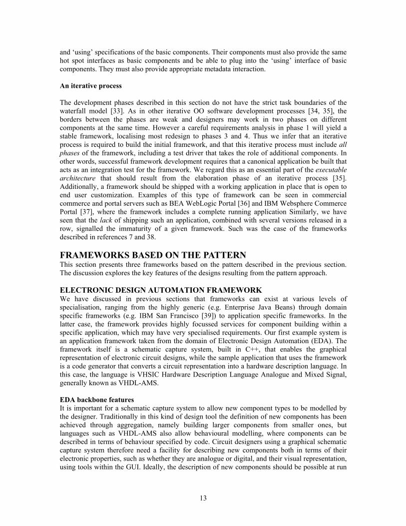
Once an additional component has been defined, it can be used in the same fashion as any basic component. Figure 7 shows a screen dump from the schematic capture interface showing a combination of basic components and a custom component, in this case a power switch, which has been created using the component building tools in the framework and integrated into a partially developed circuit diagram.
Fig. 7: Basic and additional components in a circuit diagram Implicit in this example is the underlying framework backbone which has been used to analyse the current connectivity of the components. At this stage, it is possible to check that the component’s connectivity has been correctly analysed by the schematic capture interface by invoking one of the diagnostic dialogues, the pop up visible in Figure 11. In this circuit fragment, the resistor (Resistor1) and the diode (Diode1) share a node connection (Node2) with the input connection of the power switch. The power switch output connection is to ground, and the switch control input is as yet unconnected so has a unique node name (Node1). From this example we can see that the backbone is fulfilling its role of integrating components into an appropriate connector architecture.
16

SCIENTIFIC VISUALISATION AND NUMERICAL SIMULATION FRAMEWORK Our second example framework is taken from the scientific simulation and visualisation (SimVis) application domain. As the diversity of SimVis applications has continuously grown, SimVis environments built on framework architectures have become increasingly popular [6, 8, 41]. Typical SimVis applications range from numerical simulations of computational flow dynamics with interactive visualisation back-ends to interactive medical data visualisation tools. Such applications distinguish between three user types, or roles [38, 42]. Component designers build SimVis components from source code. Application designers use interactive tools to select and assemble reusable SimVis components into custom applications. Finally, end users steer a simulation via GUI widgets, interpreted command languages, and mouse-driven virtual cameras. Often the same person assumes all three roles consecutively, such as a researcher who codes an algorithm as a component developer, builds applications to test it as an application developer, and finally uses these applications to get the desired results as an end user. A SimVis framework is successful if it satisfies the union of the requirements of the three roles and ensures an easy role transition. The framework we present here, called VISSION (VIsualisation and Steering of SImulations with Object-Oriented Networks), satisfies these requirements by using a novel component model that combines the power of development in the C++ programming language with an easy-to-use visual component representation. Several sample applications have been built with VISSION, including computational flow dynamics simulations, medical visualisations, 3D object modelling and computer vision [38, 43]. SimVis backbone features Many SimVis applications are naturally described by a dataflow model [8, 42, 44]. In this model, an application is described as a graph. The graph’s nodes represent application-specific operations, such as numerical computations, data reading or writing operations, and data display or visualisation operations. The graph’s directed edges represent the interdependencies between operations. An edge going from a component A to a component B indicates that data generated (or written) by A is used (or read) by B. When the input of some component is modified, the whole dataflow graph downstream of that component is automatically traversed and each component gets a chance to react to the change in its input. Describing SimVis applications as dataflow graphs has several advantages. First, the application designer can construct such applications from a set of predefined, generic components by connecting them in the desired way in the dataflow graph. Second, component designers can write components with specific functionality and interfaces without needing to be aware of the context (i.e. the actual dataflow graph) they will be used in. Third, end users can intuitively understand the structure of a dataflow application by looking at a visual representation of its graph, where specific icons are used to depict specific component functionalities. Fourth, the graph traversal update mechanism allows the application to maintain a consistent state automatically whenever its parameters, or inputs, change. All these advantages have been exploited in the design of VISSION. A supplementary hard requirement of the framework design was to enable component designers to write their components in C++ completely independently of the framework itself. Also, a generic integration mechanism had to be devised to upload such components, possibly at system run-time, and assemble them into dataflow graphs. A final requirement of VISSION was that components should be able to have a compiled executable model for performance reasons, crucial for large numerical simulations.
To better understand the choices made in VISSION’s design, we first briefly overview the limitations of usual designs adopted by SimVis frameworks. Most such frameworks use a white box model [38, 45]. Components inherit from a backbone superclass, contain calls to some
17

framework API, or use backbone data types to intercommunicate. All these are needed in order to provide the backbone with access to basic component services such as instantiation, connection in the dataflow graph, and intercomponent data communication. Although simple to implement, such backbones have several limitations. First, components based on white box policies are built for a specific backbone and cannot be used in a different context. In some examples of white box integration, components are also required to contain a description of their GUIs in terms of backbone API calls, which makes them even more dependent on the specific backbone [8]. Adapting third-party component libraries consisting of hundreds of components [7, 11] must be done by manual rewriting or wrapping, a very tedious task [46, 47]. Secondly, using only backbone types for component intercommunication often forces one to downgrade a sound design based on user-defined types. Overall, component integration and interoperability is limited to a small, fixed backbone API that the components have to call back on. Therefore, SimVis component developers face a complex task. As much of the conciseness, elegance, and reusability of the original OO design is lost in the integration phase, application designers get a different, usually less structured view of components than their developers. This makes role transition difficult.
To alleviate the problems of white box backbones, VISSION’s backbone consists of a combination of compiled and interpreted parts. The backbone has two main elements, a dataflow engine and a C++ interpreter. The dataflow engine performs the traversal and update of the dataflow graph starting with the component that is modified, usually by the end user, via some direct GUI-based interaction. The C++ interpreter provides dynamic loading and unloading of compiled C++ class libraries and dynamic execution of C++ source code fragments. These mechanisms are used to load component libraries on-the-fly, instantiate the desired components by calling their constructors and perform intercomponent data communication by calling component-specific read and write methods. Application components, represented here by C++ classes, do not have to inherit from some framework API as they would using white box integration. Indeed, the C++ interpreter can load and use any class, provided it is written in standard C++. SimVis connector architecture The minimal requirement for an application C++ class to be integrated in VISSION is that it has semantics for five operations; instantiation, destruction, input, output, and update. The connector specification for a C++ class must define hot spots for these operations so they can be mapped from the class interface to the framework’s interface. Since one does not want to modify existing classes to specify such hot spots, VISSION uses metaclasses to extend the C++ class notion with the five hot spot specification in a black-box manner. Concretely, a metaclass is a programming construct written in a simple object-oriented declarative language called MC++. MC++ adds a dataflow interface to a C++ class comprising a description of the inputs, the outputs, and the update operation. This interface is implemented in terms of the corresponding C++ class interface. Inputs and outputs are typed by the C++ types of their underlying methods or members. Metaclasses are object-oriented as they can inherit inputs, outputs, or update hot spots from other metaclasses. Single, multiple, and virtual inheritance are supported. Metaclass hierarchies are thus usually homeomorphic with the C++ hierarchies they use as implementation. MC++ introduces some features from the Eiffel language [47], such as feature renaming and hiding, that are not present in standard C++. Metaclasses are instantiated by the backbone and represent the nodes in the dataflow graph.
Figure 8 shows two C++ classes and their corresponding metaclasses, part of a larger hierarchy. The IVSoLight metaclass has three data inputs for a light’s colour, intensity, and on/off value, implemented by C++ class methods with the similar names (setColor, getColor, etc.), which are of types IVSbColor (a RGB colour triplet), float, and boolean
18
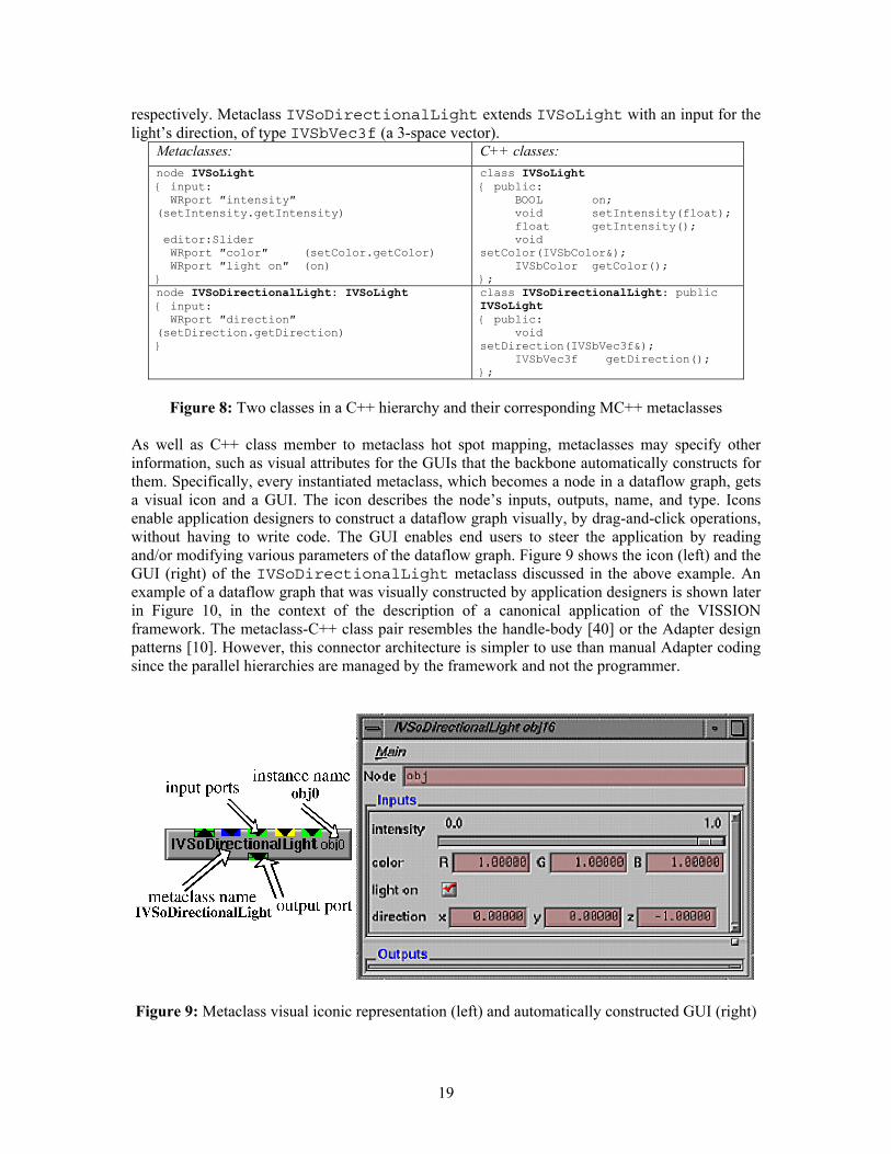
respectively. Metaclass IVSoDirectionalLight extends IVSoLight with an input for the light’s direction, of type IVSbVec3f (a 3-space vector).
Metaclasses: C++ classes: node IVSoLight { input: WRport ″intensity″ (setIntensity.getIntensity) editor:Slider WRport ″color″ (setColor.getColor) WRport ″light on″ (on) }
class IVSoLight { public: BOOL on; void setIntensity(float); float getIntensity(); void setColor(IVSbColor&); IVSbColor getColor(); };
node IVSoDirectionalLight: IVSoLight { input: WRport ″direction″ (setDirection.getDirection) }
class IVSoDirectionalLight: public IVSoLight { public: void setDirection(IVSbVec3f&); IVSbVec3f getDirection(); };
Figure 8: Two classes in a C++ hierarchy and their corresponding MC++ metaclasses
As well as C++ class member to metaclass hot spot mapping, metaclasses may specify other information, such as visual attributes for the GUIs that the backbone automatically constructs for them. Specifically, every instantiated metaclass, which becomes a node in a dataflow graph, gets a visual icon and a GUI. The icon describes the node’s inputs, outputs, name, and type. Icons enable application designers to construct a dataflow graph visually, by drag-and-click operations, without having to write code. The GUI enables end users to steer the application by reading and/or modifying various parameters of the dataflow graph. Figure 9 shows the icon (left) and the GUI (right) of the IVSoDirectionalLight metaclass discussed in the above example. An example of a dataflow graph that was visually constructed by application designers is shown later in Figure 10, in the context of the description of a canonical application of the VISSION framework. The metaclass-C++ class pair resembles the handle-body [40] or the Adapter design patterns [10]. However, this connector architecture is simpler to use than manual Adapter coding since the parallel hierarchies are managed by the framework and not the programmer.
Figure 9: Metaclass visual iconic representation (left) and automatically constructed GUI (right)
19

SimVis messaging element The messaging element in the VISSION framework is the concrete implementation of the automatic dataflow graph update discussed earlier in this section. When an end user modifies a node in this graph, for example by changing some parameter in its GUI, the backbone performs a breadth-first graph traversal from that component. For every encountered component, the backbone uses its input hot spots to let it read incoming data, its update hot spot to let it perform any computation it desires upon input change, and its output hot spots to let it write outgoing data to other components in the graph. Currently, VISSION implements all the above operations as function calls, and executes them by delegating them to the backbone’s C++ interpreter. However, this implementation of the messaging can be changed to, for example, select between synchronous or asynchronous data transfer, or accommodate components that communicate via a network, or require delayed execution. SimVis metadata format The metadata in the VISSION framework essentially consists of the metaclass declarations written in the MC++ language. The unit of reusability is a metaclass and several related metaclasses can be grouped in libraries. Such libraries can refer to each other via inclusion, much in the same way that Java packages or C++ headers use each other. When VISSION loads a metaclass library, it first parses its MC++ specification file and then loads a corresponding compiled C++ class library via its C++ interpreter. For all loaded metaclasses, VISSION displays their icons in a component library browser (Figure 10, top). Application designers can drag-and-drop these icons into the network editor (Figure 10, middle) to interactively construct the dataflow graph, as described previously. Since the MC++ file and the compiled C++ library are separate, one can easily change the two independently. For example, a component designer may change the way a given C++ library is visualised by the framework by changing the hot spot definitions, or change the way that metaclasses inherit from each other, all without changing a single line of the compiled C++ library. Conversely, this allows one to wrap existing C++ libraries for use within VISSION, even if they are provided only in binary (compiled) form. This is the situation we have encountered when wrapping the Open Inventor 3D graphics library [11] that, at the time, was available only in binary form.
20
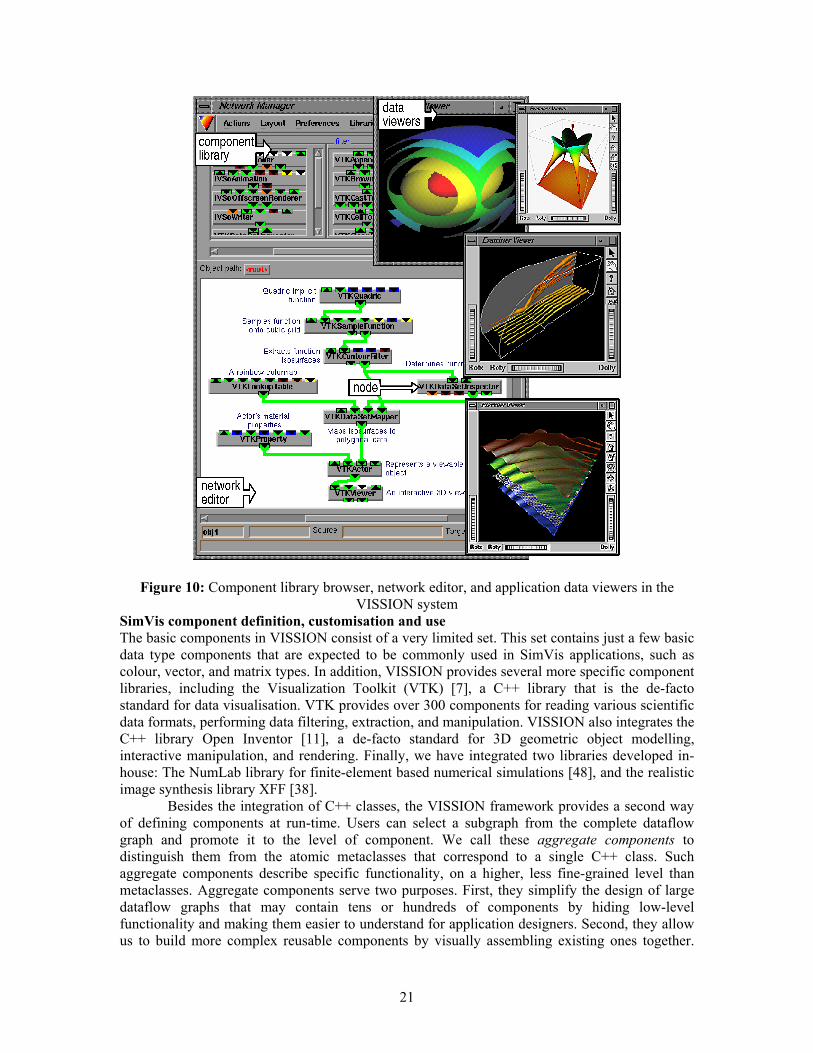
Figure 10: Component library browser, network editor, and application data viewers in the VISSION system
SimVis component definition, customisation and use The basic components in VISSION consist of a very limited set. This set contains just a few basic data type components that are expected to be commonly used in SimVis applications, such as colour, vector, and matrix types. In addition, VISSION provides several more specific component libraries, including the Visualization Toolkit (VTK) [7], a C++ library that is the de-facto standard for data visualisation. VTK provides over 300 components for reading various scientific data formats, performing data filtering, extraction, and manipulation. VISSION also integrates the C++ library Open Inventor [11], a de-facto standard for 3D geometric object modelling, interactive manipulation, and rendering. Finally, we have integrated two libraries developed in-house: The NumLab library for finite-element based numerical simulations [48], and the realistic image synthesis library XFF [38].
Besides the integration of C++ classes, the VISSION framework provides a second way of defining components at run-time. Users can select a subgraph from the complete dataflow graph and promote it to the level of component. We call these aggregate components to distinguish them from the atomic metaclasses that correspond to a single C++ class. Such aggregate components describe specific functionality, on a higher, less fine-grained level than metaclasses. Aggregate components serve two purposes. First, they simplify the design of large dataflow graphs that may contain tens or hundreds of components by hiding low-level functionality and making them easier to understand for application designers. Second, they allow us to build more complex reusable components by visually assembling existing ones together.
21
This run-time composition mechanism can be seen as a bridge between the component developer and application developer roles. Mapping the SimVis system to the framework process and model Referring to our development model, we can identify the phases of the development process as: 1. Identification of the requirements for a visually programmable dataflow SimVis system that
the framework should address 2. Development of the backbone, connector architecture, and messaging element. 3. Development of component libraries, usually by integrating existing C++ application libraries 4. Development of a canonical application, in our case a customized, specific SimVis
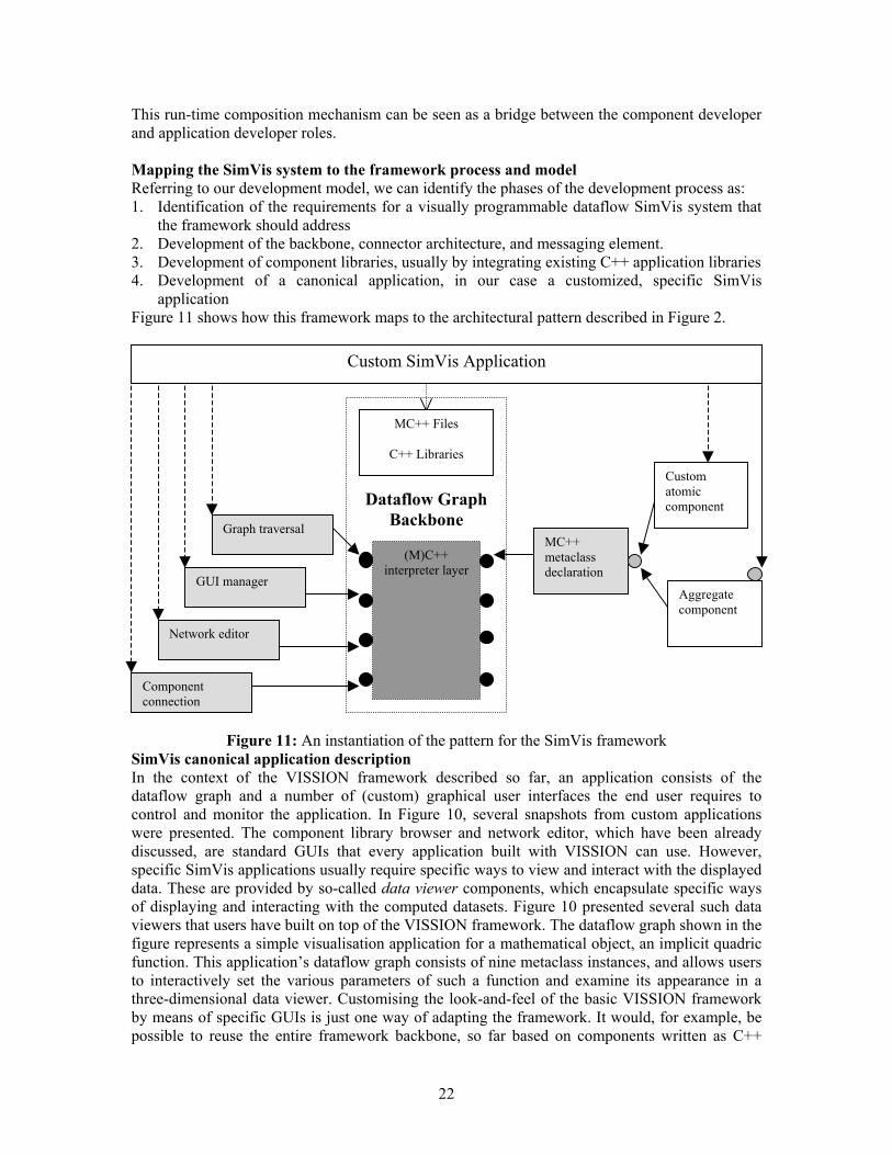
application Figure 11 shows how this framework maps to the architectural pattern described in Figure 2.
Dataflow Graph
Backbone
MC++ Files
C++ Libraries
(M)C++ interpreter layer
Custom atomic component
Graph traversal
GUI manager
Network editor
MC++ metaclass declaration
Aggregate component
Custom SimVis Application
Component connection
Figure 11: An instantiation of the pattern for the SimVis framework SimVis canonical application description In the context of the VISSION framework described so far, an application consists of the dataflow graph and a number of (custom) graphical user interfaces the end user requires to control and monitor the application. In Figure 10, several snapshots from custom applications were presented. The component library browser and network editor, which have been already discussed, are standard GUIs that every application built with VISSION can use. However, specific SimVis applications usually require specific ways to view and interact with the displayed data. These are provided by so-called data viewer components, which encapsulate specific ways of displaying and interacting with the computed datasets. Figure 10 presented several such data viewers that users have built on top of the VISSION framework. The dataflow graph shown in the figure represents a simple visualisation application for a mathematical object, an implicit quadric function. This application’s dataflow graph consists of nine metaclass instances, and allows users to interactively set the various parameters of such a function and examine its appearance in a three-dimensional data viewer. Customising the look-and-feel of the basic VISSION framework by means of specific GUIs is just one way of adapting the framework. It would, for example, be possible to reuse the entire framework backbone, so far based on components written as C++
22
class libraries, for class libraries written in another OO language, such as Java, if a Java interpreter were substituted for the C++ one currently in use. A second possible customisation, which we have already prototyped, would be to replace the messaging element currently based on direct function calls by another one, to accommodate, for example, distributed computing applications. A FRAMEWORK FOR INDUSTRIAL CONTROL SYSTEMS Our third example of applying the framework is the richest in terms of its component relationships. The industrial automation domain is a self-contained area with a long tradition of reusing hardware components. In the automation industry almost all electrical and mechanical devices and the processes involving these devices are well defined and standardised. A few examples are standard types of devices such as drives or I/O modules (basic components), machine tools and robots (as compositions of different basic devices) and standard field-busses with unified communication protocols (device interaction). The standardised interfaces of the hardware may be mirrored in the control software. Therefore, the automation domain does not suffer from the major drawbacks of software components; components that plug but do not play. Hardware standards support standard software components in an ideal way and vice versa.
Currently the industrial control systems market is dominated by proprietary solutions. Control systems such as robot controls (RCs), programmable logic controllers (PLCs) and numeric controls (NCs) are incompatible and have limited communication interfaces [49, 50]. They consist of special hardware and vendor-specific control software. The resulting problems are high development costs and longer innovation cycles, for example the Bosch robot control system rho 3 has been sold for over ten years without any significant modifications.
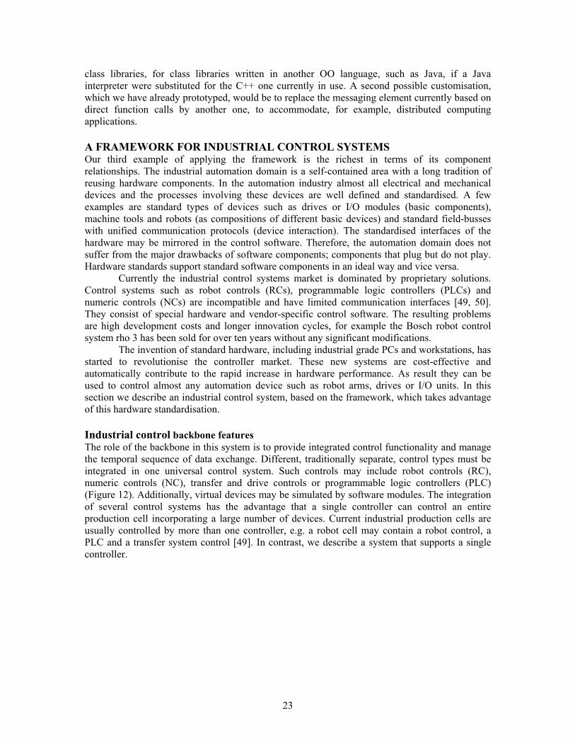
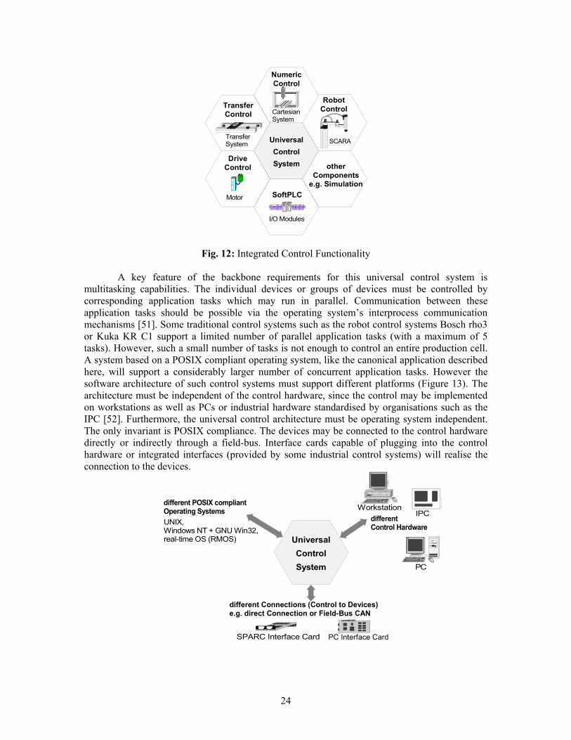
The invention of standard hardware, including industrial grade PCs and workstations, has started to revolutionise the controller market. These new systems are cost-effective and automatically contribute to the rapid increase in hardware performance. As result they can be used to control almost any automation device such as robot arms, drives or I/O units. In this section we describe an industrial control system, based on the framework, which takes advantage of this hardware standardisation. Industrial control backbone features The role of the backbone in this system is to provide integrated control functionality and manage the temporal sequence of data exchange. Different, traditionally separate, control types must be integrated in one universal control system. Such controls may include robot controls (RC), numeric controls (NC), transfer and drive controls or programmable logic controllers (PLC) (Figure 12). Additionally, virtual devices may be simulated by software modules. The integration of several control systems has the advantage that a single controller can control an entire production cell incorporating a large number of devices. Current industrial production cells are usually controlled by more than one controller, e.g. a robot cell may contain a robot control, a PLC and a transfer system control [49]. In contrast, we describe a system that supports a single controller.
23
UniversalControlSystem
SCARA
Robot Control
Numeric Control
Cartesian System
TransferControl
TransferSystem
SoftPLC
I/O Modules
DriveControl
Motor
other Components
e.g. Simulation
Fig. 12: Integrated Control Functionality A key feature of the backbone requirements for this universal control system is
multitasking capabilities. The individual devices or groups of devices must be controlled by corresponding application tasks which may run in parallel. Communication between these application tasks should be possible via the operating system’s interprocess communication mechanisms [51]. Some traditional control systems such as the robot control systems Bosch rho3 or Kuka KR C1 support a limited number of parallel application tasks (with a maximum of 5 tasks). However, such a small number of tasks is not enough to control an entire production cell. A system based on a POSIX compliant operating system, like the canonical application described here, will support a considerably larger number of concurrent application tasks. However the software architecture of such control systems must support different platforms (Figure 13). The architecture must be independent of the control hardware, since the control may be implemented on workstations as well as PCs or industrial hardware standardised by organisations such as the IPC [52]. Furthermore, the universal control architecture must be operating system independent. The only invariant is POSIX compliance. The devices may be connected to the control hardware directly or indirectly through a field-bus. Interface cards capable of plugging into the control hardware or integrated interfaces (provided by some industrial control systems) will realise the connection to the devices.
different Control Hardware
IPC
PC
Workstationdifferent POSIX compliantOperating Systems UNIX,Windows NT + GNU Win32,real-time OS (RMOS)
SPARC Interface Card PC Interface Card
different Connections (Control to Devices) e.g. direct Connection or Field-Bus CAN
UniversalControlSystem
24

Fig. 13: Platforms of the component-based Control System
Most control systems have the same pattern of behaviour: they run in cyclic loops [49, 51, 53]. In order to build a multitasking system the control needs to be split into several tasks and the components have to be allocated to these tasks (one component may be allocated to more than one task). Either processes or threads (depending on whether one or both are supported by the Operating System Interface) can be used to realise the tasks. Regardless, it is the responsibility of the backbone to manage all concurrent activities via a single controller. Industrial control connector architecture In a system such as this, much of the connector architecture is physical, i.e. based on hardware connectivity. However there is also a software layer that manages connections between components that are controlled concurrently. The software layer of the connector architecture is event driven, and connections are made between devices based on cyclic points of interaction. The relation and communication techniques between the components are aggregation relationships, with function calls and delegations as well as interprocess communication such as signalling and shared memory data exchange. Industrial control messaging element Messaging in this system is based on real time interaction between concurrent tasks, coordinated by the controller. The communication and coordination task synchronises the loops of the various application tasks. Each loop starts with a synchronisation event triggering the communication and coordination task. This synchronisation event may be implemented as a real-time signal sent by a high-precision system timer of the operating system interface component. Upon activation the communication and coordination task transmits the commands from the application tasks to the devices and reads the current data from these devices. This activates all application tasks, which receive current data from their respective devices. In general all the application tasks perform the same activities: they receive the current data, process their control application (e.g. robot control functions), transmit the resulting commands and wait until the next cycle period. Industrial control metadata format The metadata for the system is expressed using interfaces for both dynamic communication and data exchange. The interprocess communication mechanism activates tasks using the signalling functionality and timer mechanisms of the POSIX interface and operating system interface and receives the required device data. In addition it uses the data exchange interface with a concrete data structure in order to define the structure and protocol of the exchange. The data exchange interface component is used by the interprocess communication mechanism and the synchronisation and device connection components. It provides mechanisms to exchange data as well as the possibility of modifying the data structure itself (which is determined by the concrete data structure). Thus the underlying metadata format can be encapsulated as modifiable data structures that inform the dynamic components. Industrial control component definition, customisation and use This example of the framework pattern assumes a core set of components that will provide a primitive control system. Only the basic components (Device Connection, Interprocess Communication and Synchronisation and User Menu) have to be plugged into the backbone. This simple system allows a user to control the devices manually. The user is informed about the current state of the devices by the User Menu. They can then manipulate these devices by sending
25

commands using the user menu which are propagated to the hardware via the Interprocess Communication and Synchronisation and Device Connection components.
To build more sophisticated control systems, more control components are integrated into the system as additional components. These are Robot Control, Numerical Control, PLC and Generic Control Functionality. The Generic Control Functionality component may be adapted to meet user needs if these are not satisfied by the other three additional components. The services provided by both basic and additional control components are used by the application programs developed by the application developers or the end users. Mapping the industrial control system to the framework process and model Referring to our development model, we can identify the phases of the development process as: 1) Identification of the requirements for a universal control framework that supports
multitasking and data exchange. 2) Development of the backbone, connector architecture, and messaging element appropriate to
the hardware and operating system(s) applicable to the target platform. 3) Development of component libraries, usually by integrating existing dedicated libraries that
support specific hardware components. 4) Development of a canonical application, in this example a robot controller. Figure 14 shows how this framework maps to the architectural pattern described in Figure 2. Of our three examples, this is the richest use of the pattern, because the component relationships are more complex. Not only are there multiple layers of component specialisation, but these customisations are in some cases aggregated, so that a single component specialises a number of other components.
Robot Controller Application
Universal Control Backbone
Data Structures Operating System Interface
User Menu
Special ControlFunctionality
POSIX interface
Generic ControlFunctionality
Drive Controller
Control Functionality Robot Control
Coordination Controller
Interprocess communication
Device Connection
I/O Module
Data exchange interface
Concrete DeviceInterface
Figure 14: An instantiation of the pattern for an industrial robot control system
Industrial control canonical application description The application program uses one robot control component and four drive control components in order to control a four axis SCARA robot. It is not useful to have multiple instances of the basic
26
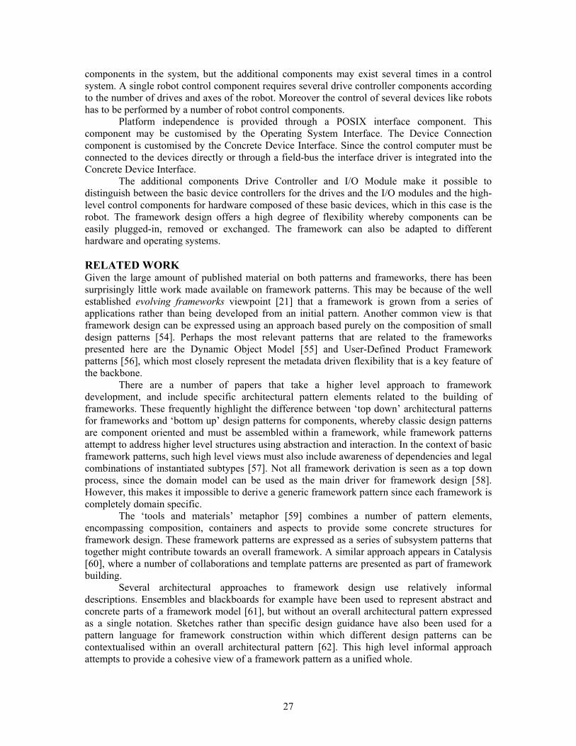
components in the system, but the additional components may exist several times in a control system. A single robot control component requires several drive controller components according to the number of drives and axes of the robot. Moreover the control of several devices like robots has to be performed by a number of robot control components.
Platform independence is provided through a POSIX interface component. This component may be customised by the Operating System Interface. The Device Connection component is customised by the Concrete Device Interface. Since the control computer must be connected to the devices directly or through a field-bus the interface driver is integrated into the Concrete Device Interface.
The additional components Drive Controller and I/O Module make it possible to distinguish between the basic device controllers for the drives and the I/O modules and the high-level control components for hardware composed of these basic devices, which in this case is the robot. The framework design offers a high degree of flexibility whereby components can be easily plugged-in, removed or exchanged. The framework can also be adapted to different hardware and operating systems. RELATED WORK Given the large amount of published material on both patterns and frameworks, there has been surprisingly little work made available on framework patterns. This may be because of the well established evolving frameworks viewpoint [21] that a framework is grown from a series of applications rather than being developed from an initial pattern. Another common view is that framework design can be expressed using an approach based purely on the composition of small design patterns [54]. Perhaps the most relevant patterns that are related to the frameworks presented here are the Dynamic Object Model [55] and User-Defined Product Framework patterns [56], which most closely represent the metadata driven flexibility that is a key feature of the backbone.
There are a number of papers that take a higher level approach to framework development, and include specific architectural pattern elements related to the building of frameworks. These frequently highlight the difference between ‘top down’ architectural patterns for frameworks and ‘bottom up’ design patterns for components, whereby classic design patterns are component oriented and must be assembled within a framework, while framework patterns attempt to address higher level structures using abstraction and interaction. In the context of basic framework patterns, such high level views must also include awareness of dependencies and legal combinations of instantiated subtypes [57]. Not all framework derivation is seen as a top down process, since the domain model can be used as the main driver for framework design [58]. However, this makes it impossible to derive a generic framework pattern since each framework is completely domain specific. The ‘tools and materials’ metaphor [59] combines a number of pattern elements, encompassing composition, containers and aspects to provide some concrete structures for framework design. These framework patterns are expressed as a series of subsystem patterns that together might contribute towards an overall framework. A similar approach appears in Catalysis [60], where a number of collaborations and template patterns are presented as part of framework building.
Several architectural approaches to framework design use relatively informal descriptions. Ensembles and blackboards for example have been used to represent abstract and concrete parts of a framework model [61], but without an overall architectural pattern expressed as a single notation. Sketches rather than specific design guidance have also been used for a pattern language for framework construction within which different design patterns can be contextualised within an overall architectural pattern [62]. This high level informal approach attempts to provide a cohesive view of a framework pattern as a unified whole.
27

The ‘Framework Recipe’ [63] provides a similarly inclusive approach, but using UML design notation. However in terms of support for frameworks design, it provides little beyond indications that there will be an application that may have configuration and/or logging. UML has also been used as the basis for extensions for framework design [64], though in this case the emphasis is on the modelling features of UML rather than providing explicit patterns for frameworks. Formal specifications have also been used to provide a higher level overview of a framework pattern [65], specifically in the context of real time distributed systems and hardware-software co-design.
Some analysis based on experience with the IBM San Francisco framework proposes a layered architecture [66], but the emphasis of this work is on process patterns rather than architectural patterns, so the model is not developed beyond a simple four-layer model of foundation layer, cross domain layer of common objects, domain specific business process layer and application layer.
In summary, despite a wide range of literature relating to patterns and frameworks, and some attempts to join the two aspects into an integrated whole, there is currently little that could be said to provide an overall architectural pattern for framework development. SUMMARY This paper has discussed an architectural pattern for designing component-based frameworks based on the forward engineering approach. It has been argued that a reverse engineering approach for developing component-based frameworks is not feasible due to the need to anticipate future extensions of the framework with components developed in-house or obtained from a third party. Integration and interoperability problems during component-based development have been outlined and the effectiveness of component-based frameworks in addressing these problems has been pointed out. The design pattern described is based on a central backbone offering services such as integration and interoperability, communication and data exchange. Components customise the backbone to suit their specific needs through the component-only customisable hot spots. Applications can customise the existing components plugged into the backbone or extend the framework with additional components to meet their specific requirements. The description of the framework design pattern is complemented by a framework development process offering a ‘good practice guide’ for developing frameworks based on the pattern. The development strategy recognises that there are several roles in the development and use of a framework, but that the original framework developer is in fact meeting a consistent need for extensibility, preferably with a simple interface that can cater for run time component creation and selection. Thus the user requirements are translated into component interfaces that define the necessary backbone support. The advantage of this approach is that it decouples framework construction from application domain analysis via the production of the component interfaces. In this way, several application domains can be satisfied by designing several frameworks, all being in fact instances of the same meta-framework. In each case the designer identifies a unique component interface appropriate to the domain. Our proposed framework pattern can, therefore, be considered a meta-framework for designing component-based frameworks. The development process depends on a logical pipeline which starts at the end-user’s requirements, passes through the application developer’s and the component developer’s, and ultimately focuses on the framework developer. Depending on the overall requirements for a component interface, the framework developer needs to provide a certain degree of (run-time) flexibility; the requirements determine the right mix between compile-time and run-time behaviour. A suitable set of guidelines can be elicited for the purpose once the union of the users’ requirements has been obtained. For each requirement, there is a statement to be made about the framework’s implementation. For example, a need to introduce new instances at run-time implies the need for a basic interpreter with type instantiation capabilities. A more demanding
28
requirement to introduce new types at run-time means that there is a need for some kind of interpreter with dynamic type-loading capabilities. If these new types are complex enough to introduce new code at run-time, then an interpreter and/or run-time operating system with support for dynamic code loading needs to be employed. For the most complex frameworks, however, where there is a need to modify types, instances and code at run-time there are several solutions, such as incremental/on-the-fly compilers, meta-types, single hierarchy (meta-type based) languages, etc. The requirements inform the framework developer of the demands likely to be placed on the framework’s backbone, and the result is a framework design specification or guideline that provides the optimum cost/benefit trade-offs for a given framework. The effectiveness of the framework design pattern and the accompanying guidelines has been shown by analysing frameworks developed for three different domains: electronic design automation, scientific visualisation and numerical simulation, and industrial control systems. The description of the three frameworks clearly demonstrates that the pattern and the associated development process are generic enough to meet the needs of disparate application frameworks. FURTHER WORK It would be useful to explore the applicability of this architectural pattern in two directions. First, it would be possible to examine how closely other existing frameworks map to the pattern, and to compare their effectiveness. For example, we indicated earlier in this paper that commercial frameworks such as rules engines and portal servers appear to have much in common with the pattern described here. An evaluation of their qualities may provide useful feedback about whether successful frameworks share architectural features with our pattern. Second, we need to develop more new frameworks using the development process and pattern. By exploring a larger number of frameworks we should be able to give more specific guidance about the various tradeoffs that are possible in the compiled versus interpreted continuum and evaluate different styles of metadata. Finally it would be useful to more closely examine the sub-patterns that appear in the framework, particularly those described by [55] and [56] to be able to give a more detailed description of the backbone architecture.
References 1. Demeyer, S, Meijler, T, Nierstrasz, O, Steyaert, P. Design Guidelines for Tailorable
Frameworks. Communications of the ACM, 1997; 40(10): 60-65. 2. Gabriel, R. Patterns of Software – Tales from the Software community, Oxford University
Press: New York, 1996. 3. Fayad, M, Schmidt, D. Object-Oriented Application Frameworks. Communications of the
ACM, 1997; 40(10): 32-38. 4. Pree, W. Design Patterns for Object Oriented Software Development, Addison Wesley: New
York, 1995. 5. Schmid, H. Design Patterns to Construct the Hot Spots of a Manufacturing Framework. The
Patterns Handbook: Techniques, Strategies and Applications, Rising, L (ed.) Cambridge University Press: Cambridge, 1998.
6. Gunn, C, Ortmann, A, Pinkall, U, Polthier, K, Schwarz, U. Oorange: A Virtual Laboratory for Experimental Mathematics, Visualization and Mathematics II, H.-C. Hege, K. Polthier (eds.), Springer, 1997: 386-394.
7. Schroeder, W, Martin, K, Lorensen, B. The Visualization Toolkit: An Object-Oriented Approach to 3D Graphics, Prentice Hall: New Jersey, 1996.
8. Upson, C, Faulhaber, T, Kamins, D, Laidlaw, D, Schlegel, D, Vroom, J, Gurwitz, R, van Dam, A. The Application Visualization System: A Computational Environment for Scientific Visualization. IEEE Computer Graphics and Applications, 1989; 9(4): 30-42.
9. Gamma, E, Beck, K. JUnit, URL http://www.junit.org .
29

10. Gamma, E, Helm, R, Johnson, R, Vlissides, J. Design Patterns: Elements of Reusable Object-Oriented Software, Addison-Wesley: Reading, Mass., 1995.
11. Wernecke, J. The Inventor Mentor: Programming Object-Oriented 3D Graphics with Open Inventor, Addison-Wesley: Reading, Mass., 1994.
12. Blanchette, J, Summerfield, M. C++ GUI Programming with Qt, second edition, Prentice Hall: New Jersey, 2004.
13. Dalheimer, M. Programming with Qt, O’Reilly: Sebastopol, CA, 2002. 14. Sun Microsystems / Java Community Process. The JavaBeans Specification, 1997. URL
http://java.sun.com/products/javabeans/docs/spec.html. 15. Buschmann, F. Reflection. Pattern Languages of Program Design 2, Vlissides, J, Coplien, J,
Kerth, N (eds.) Addison-Wesley: Reading, Mass., 1996; 271-94. 16. Sun Microsystems / Java Community Process. The Enterprise Java Beans Specification, 2003.
URL http://java.sun.com/products/ejb/docs.html. 17. IBM. Business Rules Beans, URL http://www.research.ibm.com/AEM/brb.html . 18. Szyperski C. Component Software: Beyond Object-Oriented Programming, Addison Wesley,
1998. 19. Boehm, B., Abts, C. COTS Integration: Plug and Pray. IEEE Computer, 1999; 32(1): 135-138 20. Garlan. D, Allen, R, Ockerbloom, J. Architectural Mismatch: Why Reuse is so Hard. IEEE
Software, 1995; 12(6): 17-26. 21. Roberts, D, Johnson, R. Patterns For Evolving Frameworks. Pattern Languages of Program
Design 3, Martin, R, Riehle, D, Buschmann, F (eds.) Addison-Wesley: Reading Mass., 1998; 471-86.
22. Meijer, E, Gough, J, Technical Overview of the Common Language Runtime, URL http://www.eecg.toronto.edu/~tsa/crgpapers/CLR.pdf .
23. Parnas, D. On Criteria to be Used in Decomposing Systems into Modules. Communications of the ACM, 1972; 15(12): 1053-1058.
24. Wright, C, Coutts, I. Applying Design Patterns to the Control System Framework for a Tube Inspection Machine. Patterns ’98 – The Reuse of Ideas in Software Development, OMG, Manchester, 1998.
25. IBM. OpenDoc Implementation, URL http://www-4.ibm.com/software/ad/opendoc/ . 26. Oberon Microsystems, Inc., BlackBox Developer and BlackBox Component Framework, URL
http://www.oberon.ch/ . 27. Oberon Microsystems, Inc. Portos Realtime Operating System and Denia Development
Environment for Portos, URL http://www.oberon.ch/ . 28 Buschmann, F, Meunier, R, Rohnert, H, Sommerlad, O, Stal, M. Pattern-Oriented Software
Architecture – A System of Patterns. Wiley: Chichester, 1996. 29. Fowler, M. Patterns of Enterprise Application Architecture. Addisdon-Wesley: Boston, 2003. 30. Purtilo, J. The POLYLITH Software Bus. ACM Transactions on Programming Languages
and Systems, 1994; 16(1): 151-174. 31. Johnson, R. Frameworks = (Components + Patterns). Communications of the ACM, 1997;
40(10): 39-42. 32. Sommerville, I, Sawyer, P. Requirements Engineering: A Good Practice Guide, John Wiley
and Sons, 1997. 33. Royce, W. Managing the Development of Large Software Systems: Concepts and Techniques.
Proceedings of the 9th International Conference on Software Engineering, IEEE, Monterey, 1987; 328-338.
34. Booch, G. Object-Oriented Analysis and Design, second edition, Benjamin/Cummings: Redwood City, CA,, 1994.
35. Jacobson, I, Booch, G, Rumbaugh, J. The Unified Software Development Process, Addison- Wesley: Reading, Mass., 1999.
36. BEA. WebLogic Portal
30

URL http://www.bea.com/framework.jsp?CNT=index.htm&FP=/content/products/portal/ . 37. IBM. WebSphere Portal,
URL http://www-306.ibm.com/software/genservers/commerce/portal . 38. Telea, A. Combining Object Orientation and Dataflow Modelling in the VISSION Simulation
System. Proceedings of TOOLS’ 99 Europe, Mitchell, R, Wills, A, Bosch, J, Meyer, B (eds.) ACM Press, 1999; 56-65.
39. Fayad, M, Schmidt, D, Johnson, R. Implementing Application Frameworks, John Wiley & Sons, 1999.
40. Coplien, J. Advanced C++ Programming Styles and Idioms, Addison-Wesley: Reading, Mass., 1992.
41. Abram, G, Treinish, L. An Extended Data-Flow Architecture for Data Analysis and Visualization. Proceedings of IEEE Visualization’95, G. M. Nielson, D. Silver (eds.), IEEE CS Press, 1995; 263-270.
42. Ribarsky, W, Brown, B, Myerson, T, Feldmann, R, Smith, S, Treinish, L. Object-Oriented, Dataflow Visualization Systems - A Paradigm Shift? Scientific Visualization: Advances and Challenges, Rosenblum et al (eds.), Academic Press: London and San Diego, 1994: 251-263.
43. Telea, A., Van Wijk, J. VISSION: An Object Oriented Dataflow System for Simulation and Visualisation. Proceedings IEEE VisSym ’99, E. Gröller, H. Löffelmann, B. Ribarsky (eds.), Springer, 1999: 35-43.
44. Rumbaugh, J, Blaha, M, Premerlani, W, Eddy, N, Lorensen, W. Object-Oriented Modelling and Design, Prentice-Hall, 1991.
45. Parsons, D, Rashid, A, Speck, A, Telea, A. A Framework for Object Oriented Frameworks Design, TOOLS ’99 Europe, Mitchell, R, Wills, A, Bosch, J, Meyer, B (eds.), ACM Press, 1999: 141-149.
46. Martin, R. Design Patterns for Dealing with Dual Inheritance Hierarchies in C++. C++ Report, SIGS Publications, April 1997.
47. Meyer, B. Object-oriented software construction, Prentice Hall: New Jersey, 1997. 48. Maubach, J, Telea, A. Computation and Visualisation in the NumLab Numerical Laboratory.
Visualization and Mathematics III, Hege, H, Polthier, K (eds.), Springer, 2003; 131-142. 49. Rembold, U, Nnaji, B, Storr, A. CIM: Computer Integrated Manufacturing and Engineering,
Addison-Wesley: Reading, MA, 1993. 50. Kuechlin, W, Gruhler, G, Speck, A, Lumpp, T. HIGHROBOT: A High-performance
Universal Robot Control on Parallel Workstations. Engineering of Computer Based Systems, IEEE Computer Society Press 1997; 444 – 451.
51. Gallmeister, B. POSIX.4: Programming for the Real World, O’ Reilly: Sebastopol, 1995. 52. IPC web site, URL http://www.ipc.org/ . 53. McKerrow, J. Introduction to Robotics, Addison-Wesley: Reading, MA, 1995. 54. Woolf, B. Framework Development using Patterns. Implementing Application Frameworks –
Object-Oriented Frameworks at Work, Fayad, M, Schmidt, D, Johnson R (eds.) Wiley: Chichester 1999; 621-8.
55. Johnson, R. Dynamic Object Model, 1998, http://st-www.cs.uiuc.edu/users/johnson/papers/dom/DynamicObjectModel.pdf .
56. Johnson, R, Oakes, J. The User-Defined Product Framework, 1998, http://st-www.cs.uiuc.edu/users/johnson/papers/udp/UDP.pdf .
57. Rüping, A. Framework Patterns. EuroPLoP-96 Writer's Workshop, http://www.cs.wustl.edu/~schmidt/europlop-96/ww1-papers.html .
58. Aksit, M, Marcelloni, F, Tekinerdogan, B. Developing Object-Oriented Frameworks Using Domain Models. ACM Computing Surveys (CSUR), 2000; 32(1).
59. Riehle, D, Züllihoven, H. A Pattern Language for Tool Construction and Integration Based on the Tools and Materials Metaphor. Pattern Languages of Program Design, Coplien, J, Schmidt, D (eds.) Addison-Wesley: Reading, Mass., 1995; 9-42.
31
60. D’Souza, D, Wills, A. Objects, Components and Frameworks with UML – The Catalysis Approach, Addison-Wesley: Readign Mass., 1999.
61. Wallnau, K, Hissam, S, Seacord, R. Building Systems from Commercial Components Addison-Wesley: Reading, Mass., 2002.
62. Ben-Yehuda, S. Pattern Language for Framework Construction. PLoP-97 Writer's Workshop, Washington University Technical Report 97-34, http://st-www.cs.uiuc.edu/users/hanmer/PLoP-97/Workshops.html.
63. Fontoura, M, Pree, W, Rumpe, B. UML-F: A Modeling Language for Object-Oriented Frameworks. ECOOP 2000 Object-Oriented Programming, Bertino, E. (ed.) Lecture Notes in Computer Science, 2000. 1850:63-81.
64. Erdogmus, H, Tanir, O. Developing Frameworks to Support Design Reuse. Implementing Application Frameworks – Object-Oriented Frameworks at Work, Fayad, M, Schmidt, D, Johnson, R (eds.) Wiley, 1999; 403-450.
65. Jones, R. A Framework Recipe. Building Application Frameworks – Object-Oriented Foundations of Framework Design, Fayad, M, Schmidt, D, Johnson, R (eds.) Wiley, 1999; 237-266.
66. Carey, J, Carlson, B. Framework Process Patterns – Lessons Learned Developing Application Frameworks. Addison-Wesley: Reading, Mass., 2002.
32


![A Pattern Language for the Design of Aspect Languages and ...frameworks for aspect-oriented programming (AOP) [19] are distinct but comparable. A number of languages, frameworks, and](https://static.fdocuments.us/doc/165x107/5f0f5bfe7e708231d443c4e0/a-pattern-language-for-the-design-of-aspect-languages-and-frameworks-for-aspect-oriented.jpg)


![MVC Frameworks Modernization Approach...CodeIgniter [16] is a PHP MVC pattern based open-source framework. The MVC pattern structures the development by separating the application](https://static.fdocuments.us/doc/165x107/5e566b7f73a399518353e66c/mvc-frameworks-modernization-approach-codeigniter-16-is-a-php-mvc-pattern.jpg)
