A Parametric Study on the Effects of Process Conditions on ...
8
© 2018 ISIJ 1679 ISIJ International, Vol. 58 (2018), No. 9, pp. 1679–1686 * Corresponding author: E-mail: fkarouni1@sheffield.ac.uk DOI: http://dx.doi.org/10.2355/isijinternational.ISIJINT-2018-254 A Parametric Study on the Effects of Process Conditions on Dehydrogenation, Wall Shear and Slag Entrainment in the Vacuum Arc Degasser Using Mathematical Modelling Faris KAROUNI, 1) * Bradley P WYNNE, 2) Jesus TALAMANTES-SILVA 3) and Stephen PHILLIPS 3) 1) PhD Student, Department of Materials Science and Engineering, University of Sheffield, Mappin St, Sheffield, S1 3JD, UK. 2) Department of Materials Science and Engineering, University of Sheffield, Mappin St, Sheffield, S1 3JD, UK. 3) Sheffield Forgemasters International Ltd, Brightside Lane, Sheffield, S9 2RW, UK. (Received on April 16, 2018; accepted on May 24, 2018; J-STAGE Advance published date: August 3, 2018) The effect of vacuum pressure and argon flow rate on hydrogen degassing of molten steel in a triple plug, 100 tonne vacuum arc degasser has been examined using a three phase Eulerian CFD-mass transfer coupled model. The model takes into account the interaction between the slag, steel and argon phases over a 20-minute degassing period. Increasing the argon flowrate from 13–29 Nm 3 hr −1 produces a 10% increase in the hydrogen removal ratio, generating a faster melt velocity and larger slag eye. This also results in the maximum shear stress on the ladle walls increasing by a factor of 2.2 and the shear stress integrated across the wall increasing by a factor of 3.75, thus contributing to enhance refractory erosion. Within the same flowrate range the volume of entrained slag also increases by a factor of 1.4, which may result in increased nitrogen/oxygen pickup. Reducing the vacuum pressure maintains a low equilibrium hydrogen concentration and allows more efficient hydrogen removal, with a 38% reduction in the removal ratio between 10 2 −10 4 Pa. KEY WORDS: model; CFD; degassing; ladle; vacuum; hydrogen; steel. 1. Introduction Ladle metallurgy involves the treatment of molten steel produced from primary steelmaking furnaces in order to achieve the desired chemistry and lower the hydrogen, nitro- gen, sulphur, and phosphorus content. A standard feature of these processes is the introduction of argon via a porous plug as a stirring agent to homogenise the melt and allow the transfer of dissolved gases out of the melt via diffusion into the bubbles. The presence of a buoyant slag phase above the melt serves to trap inclusions that rise with the bubbles and aids in desulphurisation. The rising bubble plume induces an upward flowing current in the melt that deforms the slag layer and forms an open eye, exposing the molten steel to the atmosphere. Central to ladle refining operations is vacuum degassing, a process through which the hydrogen and nitrogen content in steel is reduced via tank (vacuum arc degassing, VAD) or recirculating (RH degassing) methods operating under surface pressures close to 10 2 Pa. Mathematical modelling of the flow field in gas-stirred ladles have followed the finite volume computational fluid dynamics (CFD) approach based upon the volume of fluid (VOF) method, 1,2) Euler-Lagrange 3,4) and Eulerian 5,6) meth- ods. The VOF method is an interface tracking technique in which a single set of equations are solved across all phases. A sufficiently fine mesh is required to resolve each bubble making this method ideally suited for systems containing one or a small number of bubbles. The Eulerian model involves solving a separate transport equation for each phase with the assumption that the phases interpenetrate within each unit cell. This makes it less grid-sensitive and hence computa- tionally more efficient than the VOF method, 7) particularly when handling large geometries containing a large number of bubbles, for which the latter approach would require significantly more grid cells. Lou and Zhu 5) performed a detailed analysis and validation of the two-phase Eulerian method for modelling gas-stirred ladles. Predictions of the liquid velocity and turbulent kinetic energy were in close agreement with experimental data from physical models. Further simulations also showed a marginal improvement in the accuracy of the Eulerian model in comparison to the Euler-Lagrange model. The performance characteristics of a gas-stirred ladle are typically measured using the mixing time. Physical models are adopted in which tracer is injected into the melt and the time taken for the concentration to homogenise to 95% of the equilibrium composition is measured. Various papers have investigated the role of flowrate on mixing time 8–10) in gas-stirred ladles. The presence of the buoyant slag layer
Transcript of A Parametric Study on the Effects of Process Conditions on ...

ISIJ International, Vol. 58 (2018), No. 9
© 2018 ISIJ1679
ISIJ International, Vol. 58 (2018), No. 9, pp. 1679–1686
* Corresponding author: E-mail: [email protected]: http://dx.doi.org/10.2355/isijinternational.ISIJINT-2018-254
A Parametric Study on the Effects of Process Conditions on Dehydrogenation, Wall Shear and Slag Entrainment in the Vacuum Arc Degasser Using Mathematical Modelling
Faris KAROUNI,1)* Bradley P WYNNE,2) Jesus TALAMANTES-SILVA3) and Stephen PHILLIPS3)
1) PhD Student, Department of Materials Science and Engineering, University of Sheffield, Mappin St, Sheffield, S1 3JD, UK.2) Department of Materials Science and Engineering, University of Sheffield, Mappin St, Sheffield, S1 3JD, UK.3) Sheffield Forgemasters International Ltd, Brightside Lane, Sheffield, S9 2RW, UK.
(Received on April 16, 2018; accepted on May 24, 2018; J-STAGE Advance published date: August 3, 2018)
The effect of vacuum pressure and argon flow rate on hydrogen degassing of molten steel in a triple plug, 100 tonne vacuum arc degasser has been examined using a three phase Eulerian CFD-mass transfer coupled model. The model takes into account the interaction between the slag, steel and argon phases over a 20-minute degassing period. Increasing the argon flowrate from 13–29 Nm3hr−1 produces a 10% increase in the hydrogen removal ratio, generating a faster melt velocity and larger slag eye. This also results in the maximum shear stress on the ladle walls increasing by a factor of 2.2 and the shear stress integrated across the wall increasing by a factor of 3.75, thus contributing to enhance refractory erosion. Within the same flowrate range the volume of entrained slag also increases by a factor of 1.4, which may result in increased nitrogen/oxygen pickup. Reducing the vacuum pressure maintains a low equilibrium hydrogen concentration and allows more efficient hydrogen removal, with a 38% reduction in the removal ratio between 102−104 Pa.
KEY WORDS: model; CFD; degassing; ladle; vacuum; hydrogen; steel.
1. Introduction
Ladle metallurgy involves the treatment of molten steel produced from primary steelmaking furnaces in order to achieve the desired chemistry and lower the hydrogen, nitro-gen, sulphur, and phosphorus content. A standard feature of these processes is the introduction of argon via a porous plug as a stirring agent to homogenise the melt and allow the transfer of dissolved gases out of the melt via diffusion into the bubbles. The presence of a buoyant slag phase above the melt serves to trap inclusions that rise with the bubbles and aids in desulphurisation. The rising bubble plume induces an upward flowing current in the melt that deforms the slag layer and forms an open eye, exposing the molten steel to the atmosphere. Central to ladle refining operations is vacuum degassing, a process through which the hydrogen and nitrogen content in steel is reduced via tank (vacuum arc degassing, VAD) or recirculating (RH degassing) methods operating under surface pressures close to 102 Pa.
Mathematical modelling of the flow field in gas-stirred ladles have followed the finite volume computational fluid dynamics (CFD) approach based upon the volume of fluid (VOF) method,1,2) Euler-Lagrange3,4) and Eulerian5,6) meth-
ods. The VOF method is an interface tracking technique in which a single set of equations are solved across all phases. A sufficiently fine mesh is required to resolve each bubble making this method ideally suited for systems containing one or a small number of bubbles. The Eulerian model involves solving a separate transport equation for each phase with the assumption that the phases interpenetrate within each unit cell. This makes it less grid-sensitive and hence computa-tionally more efficient than the VOF method,7) particularly when handling large geometries containing a large number of bubbles, for which the latter approach would require significantly more grid cells. Lou and Zhu5) performed a detailed analysis and validation of the two-phase Eulerian method for modelling gas-stirred ladles. Predictions of the liquid velocity and turbulent kinetic energy were in close agreement with experimental data from physical models. Further simulations also showed a marginal improvement in the accuracy of the Eulerian model in comparison to the Euler-Lagrange model.
The performance characteristics of a gas-stirred ladle are typically measured using the mixing time. Physical models are adopted in which tracer is injected into the melt and the time taken for the concentration to homogenise to 95% of the equilibrium composition is measured. Various papers have investigated the role of flowrate on mixing time8–10) in gas-stirred ladles. The presence of the buoyant slag layer

ISIJ International, Vol. 58 (2018), No. 9
© 2018 ISIJ 1680
in these analyses have been factored in through the use of material analogues, which have been used to incorporate the presence of the layer and its associated thickness into the correlation of mixing time. Mazumdar11) showed that buoy-ant energy is lost from the gas plume primarily to bubble slippage and wall friction, with 10% lost to the slag layer interactions, primarily via the large velocity gradient in the melt caused by the interaction between the rising flow field and the edge of the slag eye.
The relative motion between the periphery of the slag eye and the steel current colliding with it destabilises the slag layer, causing droplets to detach from it and submerge into the melt in the direction of the flow field. This is known as entrainment. While entrainment accelerates the desulphuri-sation of the melt, it can lead to re-oxidation and nitrogen pickup. Singh et al.2) demonstrated that purging argon through a twin plug arrangement is favourable for sulphur removal in comparison to a single plug, as the former leads to more deformation of the slag layer which in turn increases the slag-steel contact area. The single plug pro-duces a larger slag eye but lowers the total interfacial area with the steel. Thicker slags tended to enhance desulphu-risation and reduce the slag eye size. The entrainment rate has been quantified in the literature in terms of the percent volume of slag entrained per unit time,12) vertical velocity at interface13) and the number of slag droplets entrained per second.14) Qualitative studies of entrainment have also been done in Eulerian15) and Euler-Lagrange16) models.
Furthermore, the slag layer affects the rate of hydrogen degassing via the size of the open eye formed from deforma-tion by the gas-liquid plume which, together with the argon bubbles, serves as an interface for mass transfer.
Various new phenomena come into play with adoption of vacuum pressures to ladle refining operations. Guo and Irons17) highlighted the relative importance of vacuum pressure over argon flowrate on the decarburisation rate of molten steel using a physical model of carbon dioxide desorption from sodium hydroxide solution. The influence of vacuum pressure on hydrogen degassing is apparent from Sievert’s Law, whereby the solubility of hydrogen in molten steel is proportional to the square root of the partial pressure of hydrogen in the gas phase. This law can be incorporated into a mass transfer model and combined with CFD analysis to predict the rate of hydrogen transfer from the melt into the gas phase.6) A three-phase Eulerian-mass transfer coupled model has been developed by the authors and validated against physical models in the literature and industrial hydrogen measurements from a VAD unit at Shef-field Forgemasters International steelworks.18)
The purpose of this paper is to perform a parametric study on the effect of vacuum pressure and argon flowrate on the hydrogen removal performance of a VAD unit. The Eulerian method18) is used to solve transport equations for the argon, steel and slag phases. Limitations on these process param-eters resulting from the deformation of the slag layer, slag entrainment and wall shear are investigated and discussed.
2. Numerical Model and Assumptions
The three-phase Eulerian method is adopted to predict the flow fields of the slag, steel and argon phases. The details of
the model are outlined in the recent study by the authors18) and summarised in Table 1.
2.1. Flow EquationsThe Eulerian method19) solves a separate set of transport
equations for each phase. Separate phases are allowed to interpenetrate, and interfacial forces are modelled using additional source terms to the momentum equation. The continuity equation for phase q is
� � ��
�� �� � �� �
� �q q
q q qt
u 0 .................... (1)
and the momentum conservation equation is
� � ��
�� �� �
� � � �� � � � �� ���
�� �
� �� �
� � � �
q q qq q q q
q eff q q qT
q q
uu u
p u u
t
, gg FIF� ... (2)
where αq=volume fraction of phase q, ρ=density, u=velocity, p=pressure, μeff=effective viscosity and t= time.
The interfacial force term FIF is expressed as
F F F F FIF drag lift VM TD� � � � .................... (3)
where Fdrag, Flift, FVM and FTD are the drag, lift, virtual mass and turbulence dispersion forces respectively.
2.2. Population Balance ModelThe discrete population balance model19) is applied to
predict the bubble size distribution (BSD). If the range of bubble sizes are discretised into a set of sizes, the volume fraction of size i is
� i iN V i N� � �i , , ,...0 1 1 ...................... (4)
where V=bubble volume. The total number of bubbles per unit volume in the ith size range Ni, depends on number density function, n
N t n V t dViV
V
i
( ) ( , )��
�i 1
........................ (5)
The population balance equation (PBE) describes the evolution of the bubble number density function across space and time
Table 1. Formulation of flow, mass transfer and bubble size model equations.
Multiphase Flow Equations Eulerian method19) for three phases (slag/steel/argon).
Interfacial Force Terms Drag,20) lift,21) turbulence dispersion22) and virtual mass.23)
Turbulence ModelStandard k-epsilon24) with Troshko and Hasan bubble induced turbulence source terms.25)
Mass Transfer Coefficient Lamont.26)
Bubble Size DistributionDiscrete population balance model19) with Luo aggregation and breakup kernels.27)
CFD Software Package ANSYS Fluent 16.1.

ISIJ International, Vol. 58 (2018), No. 9
© 2018 ISIJ1681
�� ��
�� �� ��� � ��
���
���
� � � �
n V tun V t
V
tn V t
B B D Dbrk c brk c
( , )( , ) ( , )
t ........ (6)
2.2.1. Bubble BreakageBbrk and Dbrk are the birth and death terms corresponding
to bubbles of volume V′ breaking into bubbles of volume V,
B V V V n V dVbrk
V
� � � � �� �� �( ) ( ) ( )�
.............. (7)
D V n Vbrk �� ( ) ( ) ............................ (8)
The number of child bubbles produced by the parent bubble, probability density function and breakage frequency are λ, β(V|V′) and τ(V′), respectively.
According to the Luo breakage kernel,27) ΩBR(m −3s −1), if the eddies reach a bubble of size V′ at a frequency of τ(V′)with a probability distribution function β(V|V′), then
�BR V V V� � �� �( ) ( ) ......................... (9)
The general form of the breakup kernel is obtained by integration over the dimensionless eddy size, ξ
�( ,V) .
exp[ . (
min
� � ���
���
�� � ��
VL
brk
l
0 923
1 12 0 5
2
1 3
2
11 3
1 2 3
��
�
�L
11 0 5 1
2 047
2 3
11 8 2 3 5 3
� �� �
�
�
. ) ]
.
��� �
�d
d
... (10)
where l=eddy size, L=bubble diameter and ξ=1/L.
2.2.2. Bubble AggregationBc and Dc in Eq. (6) correspond to the birth and death
terms rate due to aggregation of bubbles of volume V−V′ and volume V′.
B a V V V n V V n V dVc V� � � � � � � ��0 5
0. ( , ) ( ) ( ) ...... (11)
D a V V n V n V dVc � � � ��
�0 ( , ) ( ) ( ) ............... (12)
The aggregation kernel,27) ac (m3s −1) is the product of the binary collision frequency for bubbles of volume Vi and Vj, ωc (Vi,Vj) and collision probability λc,
a V V V Vc c i j c i j� � �( , ) ( , ) .................... (13)
where
��
c i j i j ijL L n n u� �4( ) ..................... (14)
and the characteristic velocity of bubble collision,
u L Lij i j� �� �1 43 1 3 2 3 2 3 0 5.
.� .................. (15)
The collision probability is
�
� �c
i j i j
g l i j
L L L L
L L� �
�� � ��� ��� �� �
exp. ( ) ( )
( . ) (.
0 75 1 1
0 5 1
2 32
0 5 )).
30 5We
�
��
��
�
�
��
........................................ (16)
with Weber number
WeL ul i ij�
��
2
............................. (17)
where σ= surface tension.The sauter mean diameter is given by
dN L
N LSM
i i
i i
���
3
2 ............................ (18)
2.3. Mass Transfer ModelThe reversible transfer of atomic hydrogen dissolved in
molten steel to gaseous molecular hydrogen is described by the equation
H H� � 1
22 .............................. (19)
From Sievert’s Law, the concentration of dissolved hydrogen in equilibrium with gaseous hydrogen, CH,eq is
CG RT
fpH eq
HH,
exp( / )�
�� 0
2................ (20)
where standard Gibbs free energy, ΔG0=36 485+30.46T, pH2 =partial pressure of hydrogen in gas, T= temperature, R= ideal gas constant, fH=activity coefficient of hydrogen, where
log %f e ZH HZ
wt� � �� ...................... (21)
The interaction coefficients eHZ corresponding to each alloying element (Z) are determined from the elemental composition of a melt manufactured at Sheffield Forge-masters International Limited (SFIL) steelworks listed in Table 2.
The partial pressure of hydrogen in the gas phase is expressed as
Table 2. Interaction parameters of elements in molten steel.
Element (Z) wt% Interaction Coefficient (eHZ )
C 0.15 0.06
Mn 0.5 −0.0014
P 0.005 0.011
S 0.005 0.008
Si 0.28 0.029
Cu 0.09 0.0004
B 0.0005 0.08
Cr 3–5 −0.008
Ni 1.55 −0.002
Ti 0.001 −0.08
ISIJ International, Vol. 58 (2018), No. 9
© 2018 ISIJ 1682
p pC M
C M C MH bubble
H H
H H Ar Ar2 � � � � � �
( ) ........... (22)
where pbubble is the bubble pressure and M is the molecular mass of hydrogen or argon.
The mass fraction of hydrogen in the steel and argon phases are solved using a convection-diffusion species transport equation
� � ��
�� �� �
� �� � ��
��
�
�� �
� �� �
� � ��
q q H qq q q H q
q q HT q
T qH
C
tu C
ScS
,,
,
.............. (23)
where CH=mass fraction of hydrogen, γH=hydrogen dif-fusivity, ScT= turbulent Schmidt number and μT is the turbulent viscosity.
SH,q is the hydrogen transfer rate across the gas/liquid interface. This is driven by the concentration gradient between hydrogen in the melt (CH,l) and the equilibrium concentration (CH,eq), via
S A C CH l l H eq H l, , ,( )� �� � .................... (24)
where κ is the mass transfer coefficient. The interfacial area concentration, A is defined as A=6αg/dSM, where αg is the gas volume fraction and dSM is the sauter mean diameter obtained from Eq. (18). The hydrogen pickup in the gas phase is expressed as SH,g = −SH,l.
3. Results and Discussion
The ladle geometry, material properties and process conditions are listed in Table 3. The ladle adopted for all simulations consists of three argon plugs, each of which
is located at a mid-radial position with an inter-plug angle of 45o. This design was found to produce optimal hydro-gen removal rates in a previous study by the authors28) in comparison to single and double plug designs. Based upon this standard ladle design, the purpose of the current study is to investigate the influence of VAD process conditions (argon flowrate and vacuum pressure) on hydrogen removal. The all-hexahedral computational mesh is shown in Fig. 1, together with the argon plug layout and the cross sectional plane used for analysing the resulting data.
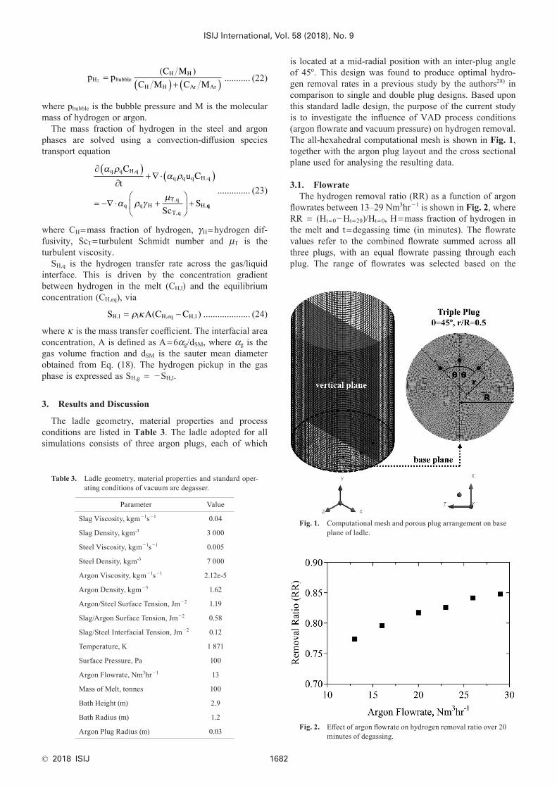
3.1. FlowrateThe hydrogen removal ratio (RR) as a function of argon
flowrates between 13–29 Nm3hr −1 is shown in Fig. 2, where RR = (Ht=0−Ht=20)/Ht=0, H=mass fraction of hydrogen in the melt and t=degassing time (in minutes). The flowrate values refer to the combined flowrate summed across all three plugs, with an equal flowrate passing through each plug. The range of flowrates was selected based on the
Table 3. Ladle geometry, material properties and standard oper-ating conditions of vacuum arc degasser.
Parameter Value
Slag Viscosity, kgm −1s −1 0.04
Slag Density, kgm-3 3 000
Steel Viscosity, kgm −1s −1 0.005
Steel Density, kgm-3 7 000
Argon Viscosity, kgm −1s −1 2.12e-5
Argon Density, kgm −3 1.62
Argon/Steel Surface Tension, Jm −2 1.19
Slag/Argon Surface Tension, Jm −2 0.58
Slag/Steel Interfacial Tension, Jm −2 0.12
Temperature, K 1 871
Surface Pressure, Pa 100
Argon Flowrate, Nm3hr −1 13
Mass of Melt, tonnes 100
Bath Height (m) 2.9
Bath Radius (m) 1.2
Argon Plug Radius (m) 0.03
Fig. 1. Computational mesh and porous plug arrangement on base plane of ladle.
Fig. 2. Effect of argon flowrate on hydrogen removal ratio over 20 minutes of degassing.

ISIJ International, Vol. 58 (2018), No. 9
© 2018 ISIJ1683
typical range expected in industry across light and heavy stirring operations.29)
The changes in hydrogen content over a degassing period of 20 minutes for argon flowrates between 13–29 Nm3hr −1 are shown in Fig. 3. The removal ratio increases from 0.77 to 0.85 between these flowrates. The velocity field, slag layer and interfacial hydrogen transfer rate contours after the first minute of degassing along the vertical plane are shown in Fig. 4. The factors contributing to this improvement in hydrogen removal are explained as follows.
As the flowrate increases, the total gas fraction in the bath increases, providing greater bubble-liquid surface area for hydrogen transfer. Furthermore, the flow field of the melt is enhanced. This has the dual effect of increasing the mixing of hydrogen within the melt and increasing the mass transfer coefficient for interfacial transfer. An added consequence of higher flowrates is the greater interaction between the melt and the slag layer. As the argon bubbles rise, the vertically flowing steel pushes slag in the radial direction, exposing a region of the melt (the slag eye) to the vacuum. The slag
eye increases in size with flowrate which increases the pro-portion of the free surface exposed to the vacuum chamber. Together, these factors result in an increase in the concen-tration gradient for hydrogen removal, interfacial area and mass transfer coefficient, which is reflected in the greater interfacial transfer rate, as shown in the mass transfer con-tour diagram.
To analyse the deformation of the slag layer during argon-stirring, the fraction of the total slag volume that is entrained beneath the lower edge of the slag layer is calculated, as shown in Fig. 5. This is plotted alongside the average verti-cal velocities of the slag phase within a 0.2 m-thick cross sectional slice at the slag-steel interface. The volume of entrained slag is found to increase by a factor of 1.4 across the flowrate range (13–29 Nm3hr −1), while there is a three-fold increase in the vertical slag velocity at the interface. The downward flow of the slag results in increasing depth of entrainment into the melt. Strong circulation currents produced by argon bubbling also causes preferential local-ised wear of the ladle refractory lining.30) Damage can occur
Fig. 3. Effect of argon flowrate on hydrogen decay profile over 20 minutes of degassing.
Fig. 4. Slag volume fraction contour and steel velocity vector plot across vertical plane after the first minute of degassing. (Online version in color.)
Fig. 5. Slag entrainment and interface velocity as a function of argon flowrate.
Fig. 6. Wall shear contour plot (Pa) for argon flowrates of 13, 20 and 29 Nm3hr −1. (Online version in color.)
ISIJ International, Vol. 58 (2018), No. 9
© 2018 ISIJ 1684
due to shear stresses dislodging grains from the refractory or chemical attack via turbulence-enhanced mass transfer from the slag layer to the refractory surface. In order to investigate this phenomena, the wall shear stress contours have been computed as a function of argon flowrate, shown in Fig. 6. Where the bubble plumes produced from these plugs meet the slag layer, the slag-steel interaction produces the region of highest wall shear in the ladle, in the upper third of the ladle, as shown by the shear stress distribution. The plumes expand radially as they rise, interacting with the wall to an increasing extent with vertical position. The shear stress on the wall reaches a peak value at the bath surface in the region of the slag layer. Within this region there is a higher stress concentration in the path of the two outermost plumes compared to that of the central plume in the triple plug arrangement. As the flowrate is increased there is a build-up of shear stress, particularly in the region at the top of the bath by the slag layer as shown in the contour plot. Most of the shear on the base is located near the two outermost plugs, at where the flow field is most intense. In addition to the side walls, the shear stress concentration within the horizontal basal plane of the ladle also increases with argon flowrate. The maximum shear stress value across the entire wall and basal plane of the ladle is plotted as a function of argon flowrate in Fig. 7. The shear stress increases by a factor of 2.2 across the flowrate range of 13–29 Nm3hr −1. The integrated shear stress over the entire wall is shown in the same figure and increases by a factor of 3.75 from 4 to 15 N between 13–29 Nm3hr −1 of argon purging. In summary, while increasing the argon flowrate is preferable for hydrogen removal, it also leads to an accom-panying increase in refractory shear stress and entrainment of slag into the melt.
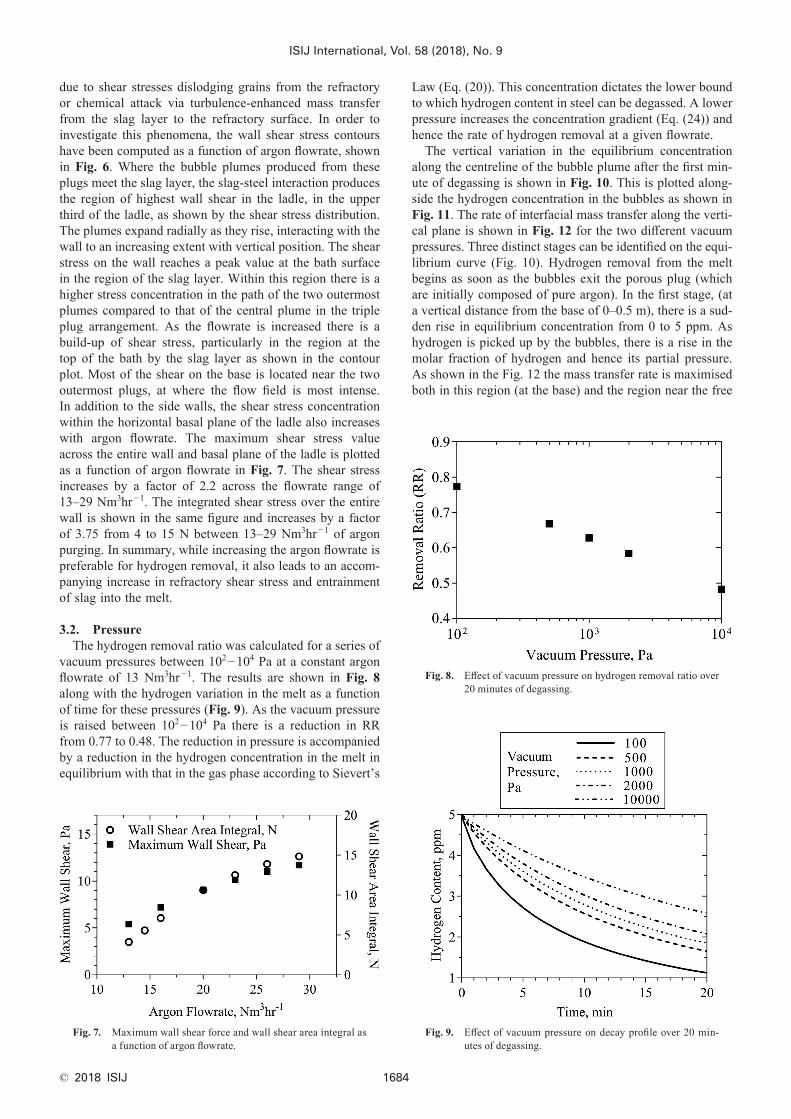
3.2. PressureThe hydrogen removal ratio was calculated for a series of
vacuum pressures between 102−104 Pa at a constant argon flowrate of 13 Nm3hr −1. The results are shown in Fig. 8 along with the hydrogen variation in the melt as a function of time for these pressures (Fig. 9). As the vacuum pressure is raised between 102−104 Pa there is a reduction in RR from 0.77 to 0.48. The reduction in pressure is accompanied by a reduction in the hydrogen concentration in the melt in equilibrium with that in the gas phase according to Sievert’s
Fig. 7. Maximum wall shear force and wall shear area integral as a function of argon flowrate.
Fig. 8. Effect of vacuum pressure on hydrogen removal ratio over 20 minutes of degassing.
Law (Eq. (20)). This concentration dictates the lower bound to which hydrogen content in steel can be degassed. A lower pressure increases the concentration gradient (Eq. (24)) and hence the rate of hydrogen removal at a given flowrate.
The vertical variation in the equilibrium concentration along the centreline of the bubble plume after the first min-ute of degassing is shown in Fig. 10. This is plotted along-side the hydrogen concentration in the bubbles as shown in Fig. 11. The rate of interfacial mass transfer along the verti-cal plane is shown in Fig. 12 for the two different vacuum pressures. Three distinct stages can be identified on the equi-librium curve (Fig. 10). Hydrogen removal from the melt begins as soon as the bubbles exit the porous plug (which are initially composed of pure argon). In the first stage, (at a vertical distance from the base of 0–0.5 m), there is a sud-den rise in equilibrium concentration from 0 to 5 ppm. As hydrogen is picked up by the bubbles, there is a rise in the molar fraction of hydrogen and hence its partial pressure. As shown in the Fig. 12 the mass transfer rate is maximised both in this region (at the base) and the region near the free
Fig. 9. Effect of vacuum pressure on decay profile over 20 min-utes of degassing.

ISIJ International, Vol. 58 (2018), No. 9
© 2018 ISIJ1685
surface. During the second stage (between 0.5 m–2.5 m) the equilibrium concentration begins to plateau at 5 ppm and then reduces. The reason for this plateau is the increase in partial pressure of hydrogen due to higher molar concentra-tion in the bubbles. The hydrogen pickup from the argon bubbles remains largely unchanged for vacuum pressures of 102 and 104 Pa in the first two stages. The influence of vacuum pressure becomes noticeable during the third stage, in the final 0.5 m of rising distance (2.5–2.9 m). The equi-librium concentration for the 104 Pa pressure case descends at a slower rate than the 102 Pa case, reaching 2.7 ppm (for 104 Pa) and 0.4 ppm (for 102 Pa). The H content within the bubbles increases at its fastest rate during this phase. Figure 12 illustrates this effect, where the 102 Pa case has a larger mass transfer rate in the top half of the bath compared to 104 Pa case. The hydrogen content in the bubbles reach a final value of 8.5% for 5.5% at the free surface for vacuum pressures of 102 Pa and 104 Pa respectively (Fig. 11). This variation in hydrogen pickup is reflected in the variation of the RR between the two pressures (Fig. 8). As the bubbles approach the surface, there is a rapid decrease in the bubble pressure with an accompanying increase in the mass frac-tion of hydrogen within each bubble. The bubble pressure in the melt decreases (due to hydrostatic pressure changes) at a faster rate than the simultaneous increase in hydrogen content of the bubbles. The net effect is that there is an overall reduction in partial pressure of hydrogen and equi-librium concentration, resulting in an increase in hydrogen transfer rate.
4. Conclusion
Hydrogen degassing in the VAD was simulated by coupling a mass transfer model to a three phase, slag-steel-argon CFD model based on the Eulerian method. The effect of argon flowrate and vacuum pressure on hydrogen removal rates, slag entrainment and wall shear were anal-ysed for a triple plug ladle of inter-plug angle, θ=45°. The conclusions can be summarised as follows:
• Argon flowrate influences the velocity field in the melt, with higher flowrates increasing the rate of convective hydrogen transfer from regions of bulk liquid to the liquid-gas interface, increasing the rate of hydrogen removal. The slag eye is simultaneously expanded providing a greater surface area for hydrogen to transfer out of the steel. There is a 10% increase in RR between 13–29 Nm3hr −1.
• Increasing the argon injection rate within this range also results in the following side effects:
⸰ A region of high wall shear stress concentration occurs in the region beneath the slag eye where the flow field in the melt and slag layer induced by the bubble plume interacts with the wall. This maximum shear stress across the wall and the total wall area-integrated stress increase by a factor of 2.2 and 3.75 across the above flowrate range, respectively, increasing the risk of refrac-tory erosion.
⸰ The volume of slag entrained into the steel melt and the vertical slag velocity at the slag-steel interface increase by a factor of 1.4 and 3, respectively. Despite aiding in the desulphurisation of steel, entrainment det-rimentally affects cleanliness via nitrogen and oxygen
Fig. 11. Change in hydrogen content in gas phase as a function of vertical position along plume centreline after the first minute of degassing.
Fig. 12. Hydrogen transfer rate in melt across vertical plane as a function of vacuum pressure after the first minute of degassing. (Online version in color.)
Fig. 10. Change in equilibrium concentration as a function of vertical position along plume centreline after the first minute of degassing.

ISIJ International, Vol. 58 (2018), No. 9
© 2018 ISIJ 1686
pickup.• Reduction of vacuum pressure has the dual effect of
increasing the rate of hydrogen removal and permitting lower hydrogen contents to be reached according to Sievert’s Law. The hydrogen removal ratio (RR) experiences a 38% reduction as the pressure is raised from 102−104 Pa. The hydrogen removal rate is governed by the concentration of hydrogen dissolved within the steel in equilibrium with that of the gas phase, which is in turn influenced by the vacuum pressure. Hydrogen transfer is concentrated in the region close to the plug exit where the gas velocity and volume fraction of gas are greatest, in addition to the near-surface region where the partial pressure of hydrogen in the bubbles is lowest.
AcknowledgementsThe authors would like to thank the Engineering and
Physical Science Research Council (EPSRC(UK)) through the EPSRC Centre for Doctoral Training in Advanced Metallic Systems (EP/L016273/1) and Sheffield Forgemas-ters International Ltd. for their financial support.
REFERENCES
1) C. A. Llanos, S. Garcia-Hernandez, J. A. Ramos-Banderas, J. J. De Barreto and G. Solorio-Diaz: ISIJ Int., 50 (2010), 396.
2) U. Singh, R. Anapagaddi, S. Mangal, K. A. Padmanabhan and A. K. Singh: Metall. Mater. Trans. B, 47 (2016), 1804.
3) S. W. P. Cloete, J. J. Eksteen and S. M. Bradshaw: Prog. Comput. Fluid Dyn., 9 (2009), 345.
4) G. Chen, S. He, Y. Li, Y. Guo and Q. Wang: JOM, 68 (2016), 2138.5) W. Lou and M. Zhu: Metall. Mater. Trans. B, 44 (2013), 1251.6) S. Yu and S. Louhenkilpi: Metall. Mater. Trans. B, 44 (2013), 459.7) F. Gauss, D. Lucas and E. Krepper: Nucl. Eng. Des., 305 (2016), 371.8) S. Joo and R. I. L. Guthrie: Metall. Trans. B, 23 (1992), 765.9) H. Tang, X. Guo, G. Wu and Y. Wang: ISIJ Int., 56 (2016), 2161.
10) M. S. C. Terrazas and A. N. Conejo: Metall. Mater. Trans. B, 46 (2015), 711.
11) D. Mazumdar and R. I. L. Guthrie: Metall. Mater. Trans. B, 41 (2010), 976.
12) A. Senguttuvan and G. A. Irons: ISIJ Int., 57 (2017), 1962.13) B. Li, H. Yin, C. Q. Zhou and F. Tsukihashi: ISIJ Int., 48 (2008),
1704.14) G. Irons, A. Senguttuvan and K. Krishnapisharody: ISIJ Int., 55
(2015), 1.15) L. Li, Z. Liu, B. Li, H. Matsuura and F. Tsukihashi: ISIJ Int., 55
(2015), 1337.16) L. Li and B. Li: JOM, 68 (2016), 2160.17) D. Guo and G. A. Irons: Metall. Mater. Trans. B, 31 (2000), 1447.18) F. Karouni, B. P. Wynne, J. Talamantes-Silva and S. Phillips: Steel
Res. Int., 89 (2018), 1700550.19) ANSYS Fluent Theory Guide, ANSYS Inc., Canonsburg, (2015).20) M. Ishii and N. Zuber: AIChE J., 25 (1979), 843.21) A. Tomiyama: Proc. 3rd Int. Conf. on Multiphase Flow, ICMF, Lyon,
(1998), 369.22) A. D. B. Burns: 5th Int. Conf. on Multiphase Flow, ICMF, Yokohama,
(2004), 1.23) D. A. Drew: Annu. Rev. Fluid Mech., 15 (1983), 261.24) B. E. Launder and D. B. Spalding: Comput. Methods Appl. Mech.
Eng., 3 (1974), 269.25) A. A. Troshko and Y. A. Hassan: Int. J. Multiph. Flow, 27 (2001),
1965.26) J. C. Lamont and D. S. Scott: AIChE J., 16 (1970), 513.27) H. Luo and H. F. Svendsen: AIChE J., 42 (1996), 1225.28) F. Karouni, B. P. Wynne, J. Talamantes-Silva and S. Phillips: Steel
Res. Int., 89 (2018), 1700551.29) A. Ghosh: Secondary Steelmaking, Principles and Applications, CRC
Press LLC, Boca Raton, FL, (2001), 62.30) R. Singh, D. Mazumdar and A. K. Ray: ISIJ Int., 48 (2008), 1033.