“A Paradigm Shift in...
72
“A Paradigm Shift in Shiphandling” (The Pivot Point) Dr. Seong-Gi SEO Captain Kevin EARL 15 th April 2015 Warsash Maritime Academy Southampton Solent University
Transcript of “A Paradigm Shift in...

“A Paradigm Shift in Shiphandling”(The Pivot Point)
Dr. Seong-Gi SEOCaptain Kevin EARL
15th April 2015
Warsash Maritime Academy Southampton Solent University

Ship-handling vs. Car-driving
The Art of Shiphandling
involves the effective use of
forces under control
to overcome the effect of
forces not under control.(Charles H. Cotter, 1963)

Timsbury Shiphandling Centre


Research Topics in Ship Manoeuvring
• Ship to Ship/Pier Interaction
• Effects of Shallow and Restricted Water
• Bank Effect
• Squat
• Scale Effect
• Hull/Propeller/Rudder Interaction• .
• .
• .• Pivot Point
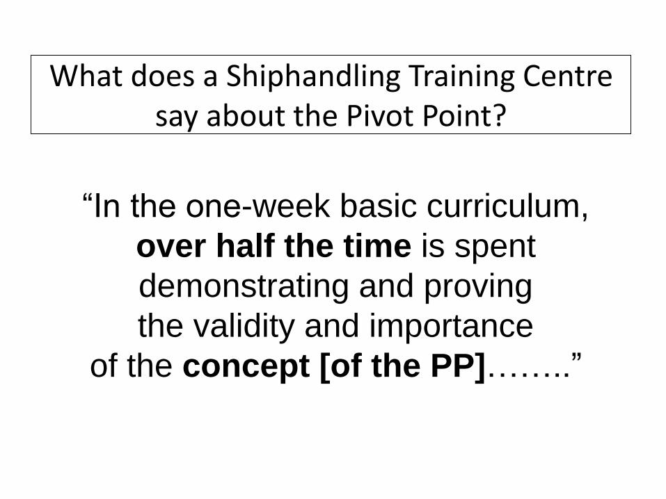
What does a Shiphandling Training Centre say about the Pivot Point?
“In the one-week basic curriculum,
over half the time is spent
demonstrating and proving
the validity and importance
of the concept [of the PP]……..”

The Pivot Point: Why needed?
• Knowledge about the position of the pivot point in a manoeuvring situation has been a basic requirement for the shiphandler to understand how and why the ship behaves in a certain way.

1. The Pivot Point of a Ship
So what is it?

Surge (eg. making sternway to a point)

Sway
Bridge marker
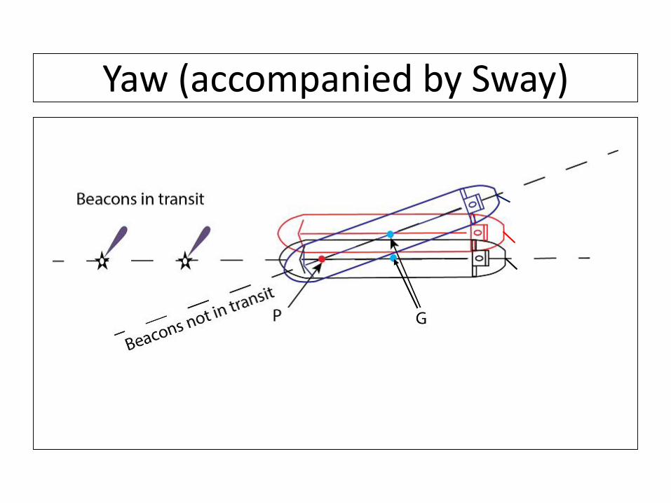
Yaw (accompanied by Sway)

The Pivot Point: Definition
v + (GP x r) = 0where, v(m/s) = sway speed of G;
G = Centre of Gravity;
P = Pivot Point;
GP(m) = distance to P from G;
r(rad/s) = yaw Speed.
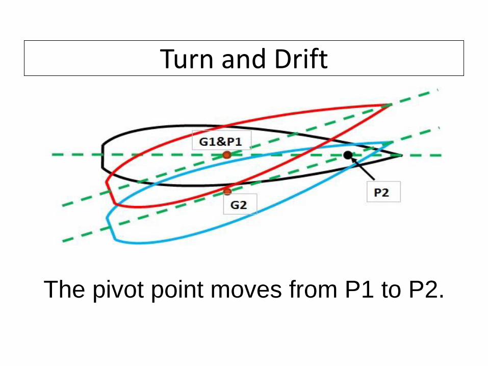
Turn and Drift
The pivot point moves from P1 to P2.

Where does the PP come from?(Turn and Drift)
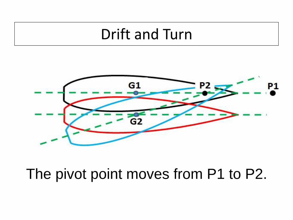
Drift and Turn
The pivot point moves from P1 to P2.

Where does the PP come from? (Drift and Turn)

Trial Data
In Zig-Zag run, the PP disappears into the forward
infinity, reappears from the aft infinity, each time
the rudder turns.
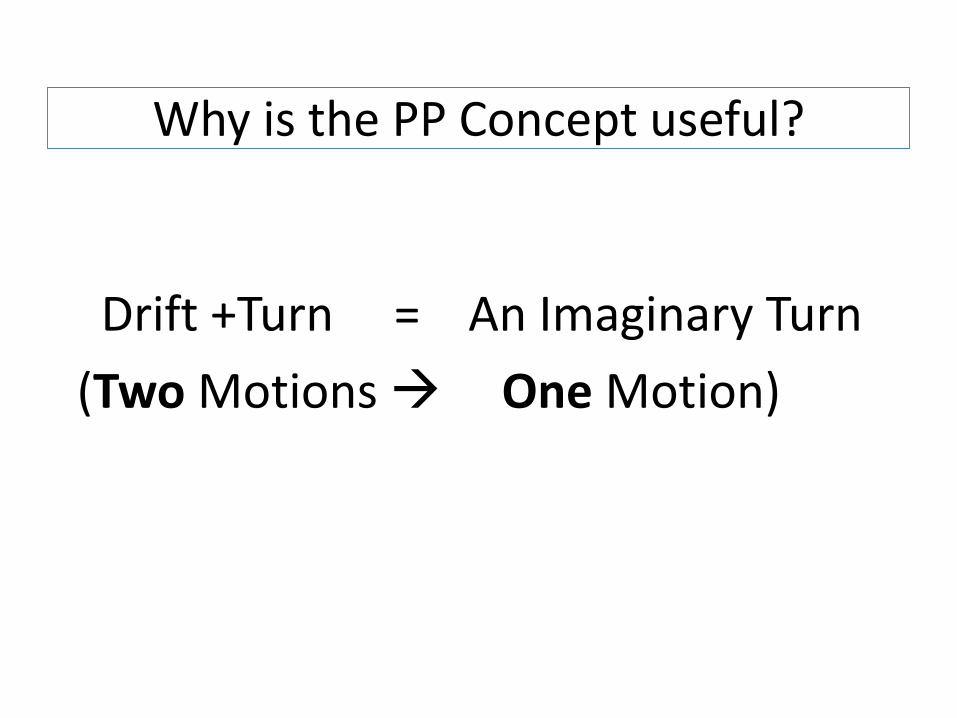
Why is the PP Concept useful?
Drift +Turn = An Imaginary Turn
(Two Motions One Motion)

2. In the Literature• Textbooks
• Training Manuals
• Lecture Notes
• Journals
• Conference Proceedings
• Theses
• Magazines
• Web Sites
•
•
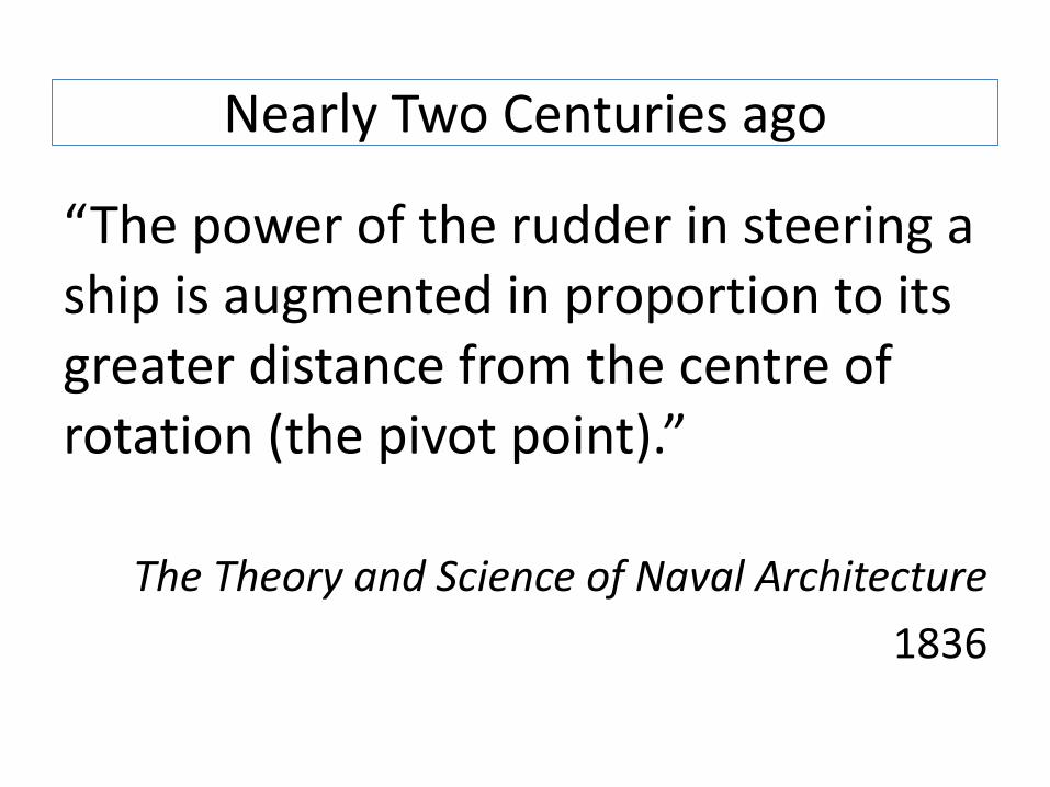
Nearly Two Centuries ago
“The power of the rudder in steering a ship is augmented in proportion to its greater distance from the centre of rotation (the pivot point).”
The Theory and Science of Naval Architecture
1836

These are still mentioned:-
- A point on the centerline about which the ship turns.
- Located at 0.25-0.33L from the bow when moving ahead, and from the stern when moving astern.
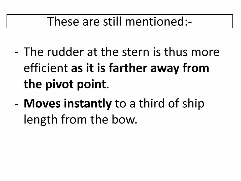
These are still mentioned:-
- The rudder at the stern is thus more efficient as it is farther away from the pivot point.
- Moves instantly to a third of ship length from the bow.

Commonly seen drawing: Where is it?
10

Commonly seen drawing: Peripatetic
11

Yet another: Effect of its Position
13

The Real Reason is:
-250
-200
-150
-100
-50
0
50
100
150
200
250
-250 -200 -150 -100 -50 0 50 100 150 200 250Axi
s Ti
tle
Axis Title
Hull

Yet another: How is it used?
14

What really is a Pivot Point?
The pivot point is a point
on a ship’s centreline which
appears to be the centre of rotation.
(It is the centre of imaginary yaw motion.)

What really is a Pivot Point?
The position of the Pivot Point is
irrelevant to the sense
of Surge motion.
What really is a Pivot Point?
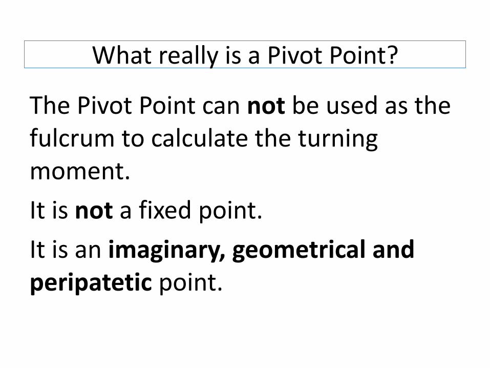
The Pivot Point can not be used as the fulcrum to calculate the turning moment.
It is not a fixed point.
It is an imaginary, geometrical and peripatetic point.

What really is a Pivot Point?
The Pivot Point comes into existence as a result of a ship’s motion.
It is not the cause of motion.

Very commonly seen drawing
P
L 2L
F F
What really is a Pivot Point?
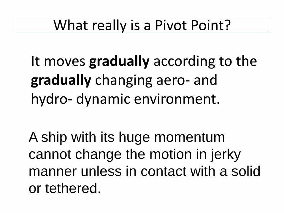
It moves gradually according to the gradually changing aero- and hydro- dynamic environment.
A ship with its huge momentum
cannot change the motion in jerky
manner unless in contact with a solid
or tethered.

The Real-Life PP Movement(Marina Class Ship)
SS -196.1 -100.004
-301.25 0Negative Clock (s) : Run Time (s) :
-250
-200
-150
-100
-50
0
50
100
150
200
250
-250 -200 -150 -100 -50 0 50 100 150 200 250Axi
s Ti
tle
Axis Title
PP
G
Hull
Jetty side
Jetty End
Jetty side2

What really is a Pivot Point?
-The pivot point is a point
on a ship’s centreline which gives
the shortest turning circle radius.
-The pivot point is a point
on a ship’s centreline at which
the drift angle is zero.
-The pivot point is a point on a ship’s
centreline whose motion vector is
always in the direction of ship’s heading.

Geometrical Consideration
PG
CL
θ
“A Paradigm Shift in Shiphandling”(The Pivot Point)

The Paradigm Shift:
Where is the pivot point?
How do I move it to
where I want it to be?

3. Obtaining the Position of PP
The changing positions can be calculated in real time using the transverse displacement of two body points.
This is possible because the PP is a result of the ship’s motion geometry.

Obtaining the Position of PP
P

How to present the information?
The Pivot Point moves gradually. This means extrapolation into the immediate future is justified.
Now the future locations can be shown together with the past and current locations.

Presentation of the Pivot Point Locations
- Each length of bar represent
one time unit apart.
- Red bars are for the future.
These could be animated to flash.
4. How do we control the PP?
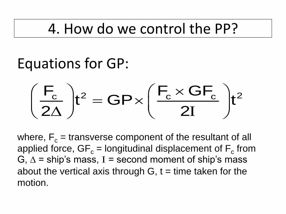
Equations for GP:
2 2c c cF F GFt GP t
2 2
where, Fc = transverse component of the resultant of all
applied force, GFc = longitudinal displacement of Fc from G, ∆ = ship’s mass, I = second moment of ship’s mass
about the vertical axis through G, t = time taken for the
motion.

4. How do we control the PP?
2
C
1GP r dV
V GF
for a solid ship with uniform density.

4. How do we control the PP?
• Negative sign (-) indicates the pivot point appears on the other side of the centre of gravity from the applied force.
• The farther the applied force is, the closer the pivot point will be to the centre of gravity.

The Coordinate System
(+ve)(-ve)OG
PF
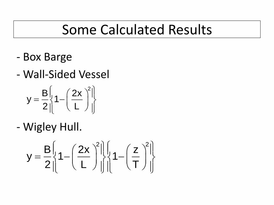
Some Calculated Results
- Box Barge
- Wall-Sided Vessel
- Wigley Hull.
2B 2x
y 12 L
2 2B 2x z
y 1 12 L T

Some Calculated Results
Box Barge Wall-Sided Wigley Hull
Cb 1.0 2/3 4/9
I 0.0017 L5 0.0007 L5 0.0005 L5
GP 0.1701 L 0.1023 L 0.1016 L
From Bow 0.3299 L 0.3977 L 0.3984 L
Assuming Fc at rudder stock, B = L/7, D = L/7,
the results below are obtained.
Some Calculated Results
The results show that
the bigger the block coefficient (Cb) is,
the closer the pivot point will be to the bow.

5. Suggested Training Exercises
Some basic manoeuvres could be included in the training program.

Yaw only
-200 -150 -100 -50 0 50 100 150 200-200
-150
-100
-50
0
50
100
150
200
Ship Turning, No Surge, No Sway(ESP)
PSE
1
3
4
2
5
Point Colors Black E:Centre of Planar Rotation Green S: Centre of Bodily RotationRed P: Pivot Point

Yaw only
-1.46 0.46 Gap between Hull and Jetty is set to (B/4)m.Clockwise Time (s) : Run Time (s) :
-250.000
-200.000
-150.000
-100.000
-50.000
0.000
50.000
100.000
150.000
200.000
250.000
-250.000 -200.000 -150.000 -100.000 -50.000 0.000 50.000 100.000 150.000 200.000 250.000Axi
s Ti
tle
Axis Title
PP
G
Hull

Yaw and Sway
-300 -200 -100 0 100 200 300-300
-200
-100
0
100
200
300
Ship Turning and Drifting, No Surge, PP between Midship and Bow (ESeP)
E
PS
Black E: Centre of Planar Rotation Green S: Centre of Bodily RotationRed P: Pivot Point

Yaw and Sway
-100.000
-50.000
0.000
50.000
-200.000 -150.000 -100.000 -50.000 0.000 50.000 100.000 150.000

Yaw and Sway
-400 -300 -200 -100 0 100 200 300 400-400
-300
-200
-100
0
100
200
300
400
Ship Turning and Drifting, No Surge, PP ahed of Bow (ESeP)
E
PS
Black E: Centre of Planar Rotation Green S: Centre of Bodily RotationRed P: Pivot Point

No Surge-208 7Clockwise Time (s) : Run Time (s) :
-250.000
-200.000
-150.000
-100.000
-50.000
0.000
50.000
100.000
150.000
200.000
250.000
-250.000 -200.000 -150.000 -100.000 -50.000 0.000 50.000 100.000 150.000 200.000 250.000Axi
s Ti
tle
Axis Title
PP
G
Hull

Yaw and Surge
-400 -300 -200 -100 0 100 200 300 400-400
-300
-200
-100
0
100
200
300
400
Ship Turning and Moving Forward,No Drifting,S and P Coincide (EeSP)
E
S P
Black E: Centre of Planar Rotation Green S: Centre of Bodily RotationRed P: Pivot Point

Surge, Turn, No Drift
-86.086 85.086 Gap between Hull and Jetty is set to (B/4)m.Run Time (s) :Clockwise Time (s) :
-250.000
-200.000
-150.000
-100.000
-50.000
0.000
50.000
100.000
150.000
200.000
250.000
-250.000 -200.000 -150.000 -100.000 -50.000 0.000 50.000 100.000 150.000 200.000 250.000Axi
s Ti
tle
Axis Title
PP
G
Hull

General Planar Motion
-400 -300 -200 -100 0 100 200 300 400-400
-300
-200
-100
0
100
200
300
400
Ship Moving Forward and Turning and Drifting, (ESePe)
PS
E
Black E: Centre of Planar Rotation Green S: Centre of Bodily RotationRed P: Pivot Point
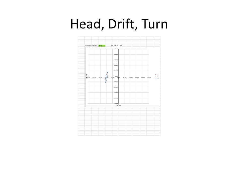
Head, Drift, Turn-81.5 80.5Clockwise Time (s) : Run Time (s) :
-250.000
-200.000
-150.000
-100.000
-50.000
0.000
50.000
100.000
150.000
200.000
250.000
-250.000 -200.000 -150.000 -100.000 -50.000 0.000 50.000 100.000 150.000 200.000 250.000Axi
s Ti
tle
Axis Title
PP
G
Hull

Short Round

Entering a Cut
An Example of Actual Manoeuvre
CMA CGM Marco Polo
(L = 396 m, 16020 TEU)
At Southampton Container Terminal

An Example of Actual Manoeuvre
• The following sequence of screen shots have been taken from the PPU on the departure of the “CMA CGM Marco Polo” from Southampton. The pilots portable unit is an AD Navigation ADX-XR which includes RTK, giving a very precise position . The performance criteria are:-
• Position Accuracy: 1-2 cm (RTK mode)0.8 m with EGNOS/WAAS 2 m uncorrected GPS/GLONASS
• Bow and Stern Speed: 1 cm/sec (0.02 knots)
• Vertical/Squat: 2-3 cm (RTK mode)
• Heading: 0.01 deg (20m POD separation)
• Rate of Turn: 0.1 deg/min

Minding the PP

Minding the PP
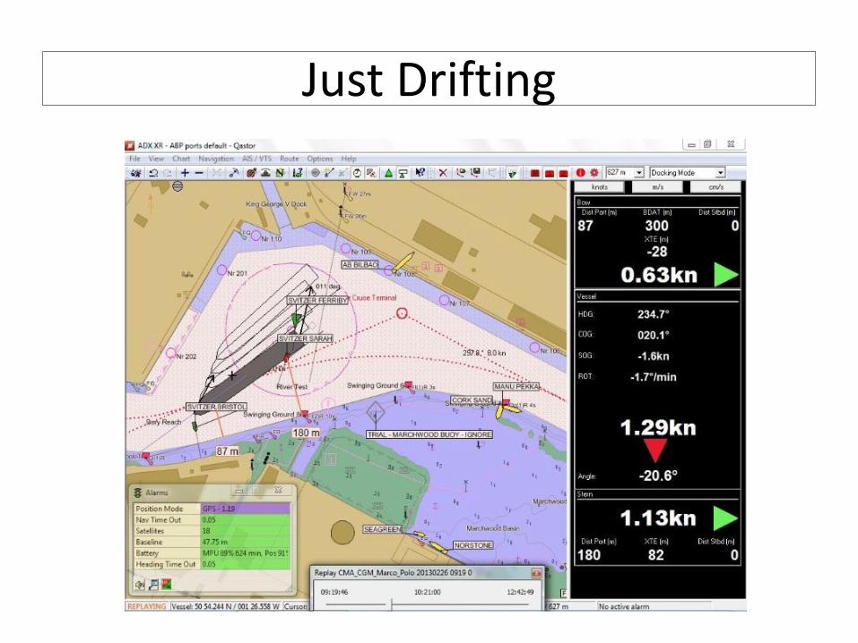
Just Drifting
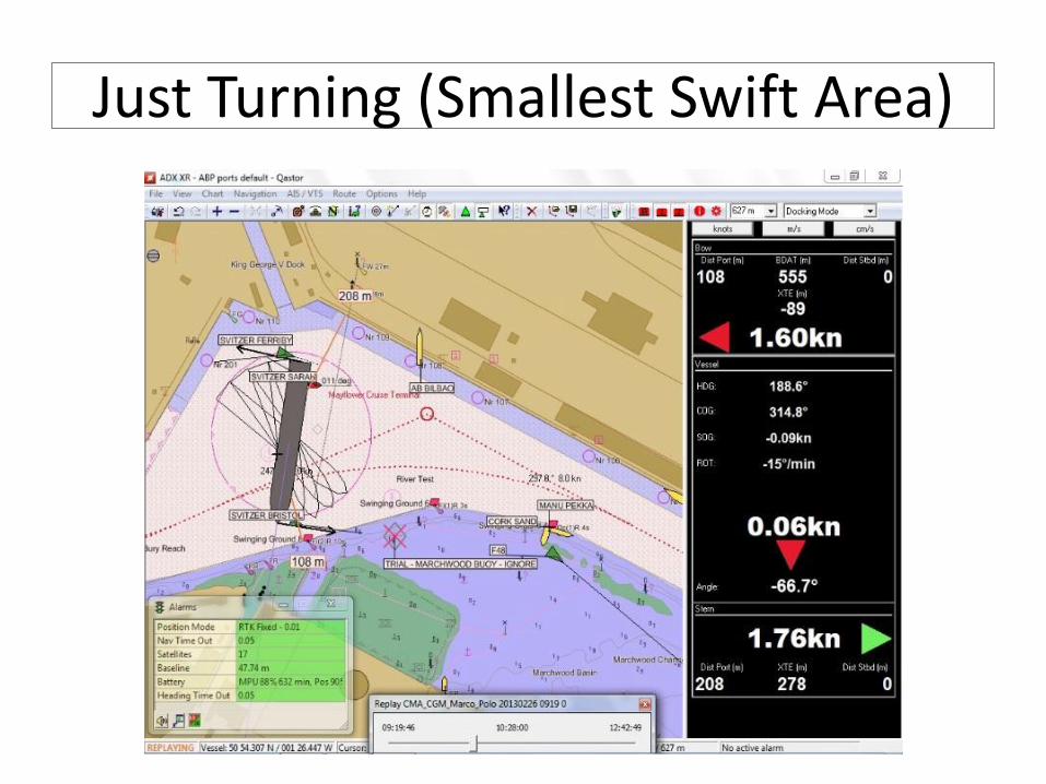
Just Turning (Smallest Swift Area)

Still conscious of the PP
Future Works
• Safer and More Efficient
Ship Handling Modules for:-
- the Bridge
- Remote Control Systems
- Auto-Pilot Systems
- Simulation Packages
(commercial & educational)

If you are interested in further development of this topic, please, contact the author direct.